materials state awareness for structures needs and … · materials state awareness for structures...
TRANSCRIPT

Materials State Awarenessfor Structures
Needs and Challenges
Eric Lindgren and Charles BuynakNondestructive Evaluation Branch
Materials and Manufacturing Directorate Air Force Research Laboratory
12th International Symposium on Nondestructive Characterization of Materials
Blacksburg, VAJune 23, 2011
88ABW-2011-1542

Disclaimer
• The views expressed in this presentation are those of the author and do not reflect the official policy or position of the United States Air Force, Department of Defense, or the United States Government
88ABW-2011-1542

Outline
• Definition of MSA• Background: Current State• Desired future state• Strategy / technical hurdles• Case studies• Challenges• Opportunities
88ABW-2011-1542

Material State Awareness
Definition
Reliable Nondestructive Quantitative Materials / Damage Characterization Regardless of Scale
Attributes– Complete characterization: size, location, etc.– Material agnostic: metals, polymers, ceramics,
composites– Metrics for reliability: capability and precision
88ABW-2011-1542

Background: Current Practice
• ASIP: MIL-STD-1530C– Damage tolerance: three options
• Slow crack growth (most common option) – Periodic inspection based on NDE capability
• Fail-safe multiple load path• Fail-safe crack-arrest
– Service life extension via risk management• Preferred (i.e. low cost) approach is periodic inspection
• PSIP: MIL-STD-3024– Essentially a safe life approach– … but crack growth criteria also enforced– Components retired with remaining serviceable life
88ABW-2011-1542

ASIP Perspective
Gallagher, et. al., 2007 Aging Aircraft Conference 88ABW-2011-1542
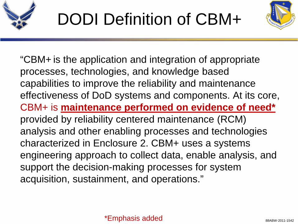
DODI Definition of CBM+
“CBM+ is the application and integration of appropriate processes, technologies, and knowledge based capabilities to improve the reliability and maintenance effectiveness of DoD systems and components. At its core, CBM+ is maintenance performed on evidence of need*provided by reliability centered maintenance (RCM) analysis and other enabling processes and technologies characterized in Enclosure 2. CBM+ uses a systems engineering approach to collect data, enable analysis, and support the decision-making processes for system acquisition, sustainment, and operations.”
*Emphasis added 88ABW-2011-1542

Enclosure 2CBM+ EXAMPLES AND CHARACTERISTICS
A variety of advanced engineering, maintenance, and information system technologies as well as contemporary business processes support CBM+, which include, but are not limited to*, the following characteristics and examples:
• Hardware: system health monitoring and management using embedded sensors; integrated data bus. • Software: decision support and analysis capabilities; on and off equipment; appropriate use of
diagnostics and prognostics; automated maintenance information generation and retrieval. • Design: open system architecture; integration of maintenance and logistics information systems;
interface with operational systems; designing systems that require minimum maintenance; enabling maintenance decisions based on equipment condition.
• Processes: RCM analysis; a balance of corrective, preventive, and predictive maintenance processes; trend-based reliability and process improvements; integrated information systems providing logistics system response; CPI; Serialized Item Management (SIM).
• Communications: databases; off-board interactive communication links. • Tools: integrated electronic technical manuals (digitized data); automatic identification technology;
item unique identification (IUID); portable maintenance aids; embedded database interactive training. • Functionality: low ambiguity fault detection, isolation and prediction; optimized maintenance
requirements and reduced logistics support footprints; configuration management and asset visibility.
*Emphasis added 88ABW-2011-1542

Interpreting Encl 2
Leaves approach to the discretion of the end-user:• Does not require in-situ NDE/SHM, or any other
approach
Addresses all supporting structure, but not the core requirement, which is:• How do you determine the “condition” that requires
maintenance?
• Highest level includes tracking by individual tail number, but where to draw line on what is technically feasible and cost effective?
88ABW-2011-1542

Inferred Requirement
Determine “condition” of system• Quantitatively characterize damage
– Presence, location, size (in all dimensions) of flaws
• Statistically validated capability to enable risk determination
Attributes:• Ill-posed inverse problem
– 1 to 3 measured variables with many unknowns
• Probabilistic in nature– Error propagation and uncertainty determination a
challenge88ABW-2011-1542

Current NDI Capabilities
Detection: Damage Type*
Location and Characterization:• Only manual interpretation (grease pen and ruler)• Quantitative inversion in its infancy: R&D is addressing deterministic cracks in
simple geometric configurations • Will be pervasive for all sensing locations and damage types
* Refers to fatigue cracks that meet ASIP Inspection requirements** Deterministic is defined as a known damage formation location
Where Sensing is Performed
Deterministic**Surface Breaking
Non-deterministicSurface Breaking
DeterministicBuried
Non-DeterministicBuried
Depot Available Available Limited LimitedField Available Limited Limited Not Available
On-board Flight Test Flight Test Not Available Not Available
88ABW-2011-1542

Materials Level Scale of Damage
Increasing Age and Degradation
Cap
abili
ty
Cycles / Time
Mission Requirement
Dislocation density saturation / PSBMicrocrack formation
Local heating / hotspot
Macrocrack formation
Degraded module efficiencies (temperatures, pressures, speeds)
Changes in blade-tip timing/displ.
Vibration changes
Crack growth
88ABW-2011-1542

Attributes of NDE at Each Scale
Increasing Age and Degradation
Cap
abili
ty
Cycles / Time
System Monitoring• Quasi-Continuous• Rate of damage progression• Short-term asset management
(months / weeks)
Material Monitoring• Global characteristics / continuum damage• Identify tails of life distribution• Long-term asset management (decades)
Mission Requirement
Component Monitoring• Scheduled inspections• Looking for local damage / cracks• Mid-term asset management (years)
88ABW-2011-1542

Strategy
• Use forward models to determine response– Need validated models of inspection methods that integrate
realistic structures
• Use models, empirical data, engineering expertise to determine coherent/incoherent noise
• Use feature extraction to locate response buried in noise
• Repeat if needed
• Generate statistical measured results that include confidence of estimation
88ABW-2011-1542

Key Attribute
• Strategy does not change as a function of scale, but
• Confounding factors will:– Macro: variability in geometry, assembly,
maintenance, and usage
– Micro: variability in grain structure, material properties, tailored/composite constituents
– Atomic: variability in localized composition, material change, and geometry
88ABW-2011-1542

Empirical Data
• Approach has modeling centric aspects– Materials and Manufacturing Directorate initiative in
Integrated Computation Materials Science and Engineering (iCMSE)
• Empirical/Experimental data is critical– Required to calibrate and validate modeling efforts
• Benchmarking is very important
– Fills the data gaps that cannot be addressed via modeling
88ABW-2011-1542

Benefits / Payoff
Material State Awareness• An enabler for risk-based management of assets (ASIP,
PSIP, MechSIP)• An enabler for Air Force initiatives to improve maintenance
processes – Condition-based Maintenance• Increases aircraft availability
– enables improved maintenance planning– minimizes unanticipated maintenance
• Assures tailored material properties are realized before and during implementation and deployment
• Enables improved performance of USAF Systems
88ABW-2011-1542

Case Studies
• Macro-scale: cracks at fasteners
• Micro-scale: tailored material properties for propulsion component
• Atomic-scale: degradation of thermal protection material
88ABW-2011-1542

Macro-scale: Cracks at Fasteners

Factors Affecting NDE for Cracks at Fastener in Two-layered Structure
A. NDE method:1. NDE technique2. Transducer/probe design3. Contact condition with part
(direct, immersion, air-coupled)4. Scan plan (directions, resolution, orientation)B. Part geometry, material and condition:1. Layer material, number, and thickness (shims)2. Outer layer surface condition (paint,
very thick coatings, corrosion) 3. Fastener material / type / head condition4. Hole geometry (oblong, off-angled, surface
conditions, scratches, chatter, tool marks)5. Fastener hole fit (asymmetric fit, irregular contact
conditions / loading, sealant)6. Gaps / sealant between layers (aging)7. Presence of metal shavings8. Bushings, residual stress around holes9. Proximity of adjacent fasteners and edges10. Presence and condition of repairs
C. Flaw characteristics:1. Flaw number (number of cracks per fastener
site)2. Flaw type (cracks, EDM notch)3. Flaw location (layer, location in layer:
surface, mid-bore, eye-brow cracks)4. Flaw orientation (around fastener site, skew
angle from normal)5. Flaw dimensions6. Material within flaw (none, use of filler
material, filled with sealant/paint/fluids)7. Flaw morphology (regular, irregular)8. Flaw conditions at faces
(contact conditions, residual stress)
List first presented in 200588ABW-2011-1542

3D Analytical Model Transient Solution (around hole at r = 3 mm for θ=0:π)• fastener site inspection – angled-beam shear wave: [φ=45º, γ=0º] (SV)
• wave propagates around hole and leaks into far field (use for detection)
Spiral Creeping Waves:3D Analytical Model Solution
x
y
z
M(r,θ,x)
a
x
y
z
M(r,θ,x)
a
p
propagationdirection
polarizationdirection
x
y
plane wave
a
θ=0
θ=π
locations for 13 plots
88ABW-2011-1542

Representative Complexity
• Multiple materials in structure• Critical flaws in hard to inspect locations• Hard to access area of interest
Pictures from: J. Hoffmann, J. Ullet, B. Drennen, “Development of a Nondestructive Inspection (NDI) Approach based on Bolt Hole Ultrasonic Testing (BHUT) for complex, multi-layered Aircraft Structures” ASIP 2007, http://www.asipcon.com/proceedings/Weds_1130_Drennen.pdf
Note Variability
88ABW-2011-1542

Confounding Details
Example: Sealant condition assumption:
• How long? How much? How much patience?
0.001
0.010
0.100
1.000
0.0 0.1 0.2 0.3 0.4 0.5 0.6 0.7 0.8 0.9 1.0
pre-POD (wet fasteners)PODin field distribution
Distribution
Rat
io o
f RIS
am
plitu
de to
refle
ctio
nfro
m fa
sten
er h
ole
88ABW-2011-1542

Micro-scale: Tailored Material Properties for Propulsion Component

Microstructural Hybrid
• Multiple Grain Sizes in One Component
Pictures from: J. Gayda, T.P. Gabb, and P.T. Kantzos, “The Effect of Dual Microstructural Heat Treatment on an Advanced Nickel-based Disk Alloy, Superalloys 2004, K.A. Green, et. al. eds., TMS 2004 88ABW-2011-1542

Scattering: Factors
88ABW-2011-1542

Moving to Solution
• Forward model wave propagation
• Verify with experimental data– Contact ultrasound– Scanning immersion ultrasound– Scanning laser vibrometer ultrasound
• Integrate into refined forward model to enable inversion
88ABW-2011-1542

Atomic-scale: Degradation of Thermal Protection Material

Ceramic Matrix Composites: NDE Needs
Basic NDE needs/requirement areas*:
– No-Go/Go for accept/reject of as produced components
– In-service inspection for replace/continue operations decisions
– Assessment of degree/extent of in-service damage• Oxidation, corrosion, fatigue, etc…
– Determination of quality of damaged component repair* According to Mil-HDBK-17-5, Volume 5 of 5, Department of Defense Handbook, Composite Materials Handbook,
17 June 2002
88ABW-2011-1542

SYSTEM
Electromagnetic NDE
IN OUT
ω ω
void
Degraded region
• Significant damage can be detected due to dramatic material changes
• Degradation (precursor damage) may result in subtle changes in material response
88ABW-2011-1542

Band designations from 1) J Mater Sci 42:5891 (2007) 2) Chem. Mater. 22(8) 2541 (2010).
Highlighted are the areas of interest in terms of the chemical change within the composite
Reflectance Spectroscopy of CMCs
Si-C
O-Si-OSi-O-Si
88ABW-2011-1542

Summary
Material State Awareness• Definition: Reliable Nondestructive Quantitative
Materials/Damage Characterization Regardless of Scale
• Need: To improve life management and tailored property validation for USAF Assets
• Challenges: Variability, Scale, Ill-posed Inversion, e.g.– Determining meaningful change– Lack of historical behavior– Clutter in signal interpretation– Extraction of relevant features– New material developments
88ABW-2011-1542