materials science and engineering a - uwaterloo.ca · materials science and engineering a 551...
TRANSCRIPT

M
Sa
b
c
a
ARRAA
KTsMHR
1
cibnfer(caTgsewtA
(
0h
Materials Science and Engineering A 551 (2012) 73– 81
Contents lists available at SciVerse ScienceDirect
Materials Science and Engineering A
jo ur n al hom epage: www.elsev ier .com/ locate /msea
icrostructure–hardness relationship in the fusion zone of TRIP steel welds
.S. Nayaka,∗, V.H. Baltazar Hernandeza,b, Y. Okitaa,c, Y. Zhoua
Center for Advanced Materials Joining, Mechanical and Mechatronics Engineering, University of Waterloo, Waterloo, ON N2L 3G1, CanadaMPyM-EPMM Academic Unit of Engineering, Autonomous University of Zacatecas, C.P. 98000 Zacatecas, MexicoJoining & Strength Research Department, JFE Steel Corporation, Chiba 260-0835, Japan
r t i c l e i n f o
rticle history:eceived 25 November 2011eceived in revised form 27 April 2012ccepted 29 April 2012vailable online 8 May 2012
eywords:ransformation induced plasticity (TRIP)
a b s t r a c t
Fusion zone of three TRIP steels, categorized as AT: C–Mn–Al, AST: C–Mn–Al–Si and ST: C–Mn–Si, inresistance spot welding was characterized with respect to microstructure, phase analysis, and hardness.The fusion zone microstructure was found to depend on chemistry: (i) AT steel contained ferrite phasesurrounded by bainite and martensite regions, (ii) AST steel showed a bainite structures along withmartensite laths and interlath retained austenite, whereas (iii) ST steel constituted single phase marten-site laths with interlath austenite. X-ray diffraction study indicated that retained austenite fraction inthe fusion zone increases with increase in Si content in it. The AST fusion zone hardness lies between
teelicrostructureardnessesistance spot welding
those of the AT and ST steels; the ST fusion zone hardness was higher than that of AT steel because ofthe single phase martensite microstructure. Comparison of fusion zone microstructure and hardness toearlier study on laser welding of the TRIP steels with similar chemistries revealed that higher coolingrate in resistance spot welding led to higher fusion zone hardness compared to laser welding; whichwas attributed either to decrease in softer ferrite phase (AT steel) in the microstructure or refinement ofmartensite laths (ST steel).
© 2012 Elsevier B.V. All rights reserved.
. Introduction
Automobile industries demand lightweight materials withoutompromising the strength. Many materials have been competingn the race to accomplish the requirement of automotive industriesut advanced high strength steels (AHSS) have been the win-er. Because, AHSS reduce the vehicle weight leading to reduced
uel consumption and increase the passenger safety due to highernergy absorption and stiffness of the body. AHSS is commonlyeferred to dual phase (DP), transformation induced plasticityTRIP), complex phase (CP), and martensitic (M) steels which areharacterized as steels with a yield strength above 300 MPa and
tensile strength higher than 600 MPa [1,2]. Among all the AHSS,RIP steels have high strength combined with good uniform elon-ation due to hard–soft composite structure given by its varioustructural constituents like ferrite, bainite, martensite and carbon-nriched retained austenite [3–6]. TRIP steel is commonly alloyed
ith, apart from Mn, Si or Al to suppress cementite formationhus forcing more carbon into retained austenite as both Si andl are insoluble in cementite [1,2]. The mechanical properties of
∗ Corresponding author. Tel.: +1 519 888 4567x35256; fax: +1 519 885 5862.E-mail addresses: [email protected], [email protected]
S.S. Nayak).
921-5093/$ – see front matter © 2012 Elsevier B.V. All rights reserved.ttp://dx.doi.org/10.1016/j.msea.2012.04.096
the TRIP steels have been the special attention for the possibleimplementation in industries. No difference in mechanical prop-erties of TRIP steels is observed when all the Si in it is replaced byAl [7]; but interestingly C–Mn–Al TRIP steel exhibits a remarkableTRIP effect during tensile testing compared to C–Mn–Si TRIP [8]. Inthis regard, TRIP steel alloyed with both Si and Al are being con-sidered based on concept of partial replacement of Si by limitedamount of Al [9].
Automotive industries adopt various welding techniques to joinsteel sheets for the assembly of car bodies and various structuralcomponents [10–18]. However, resistance spot welding (RSW) iscurrently one of the dominant methods for manufacturing auto-body structure [10,11,17,19–22]. In welding research, studies onwelding of TRIP steels have been reported earlier by different pro-cesses [11–18]. For example, in laser beam welding (LBW) C–Mn–SiTRIP revealed a single phase martensite microstructure in thefusion zone [12–14]; whereas C–Mn–Al fusion zone formed a mul-tiphase microstructure containing skeletal ferrite, bainitic ferrite,martensite and retained austenite [14–16]. Like in laser welding,C–Mn–Si fusion zone in RSW also formed single phase microstruc-ture of martensite [11,17]. Although there are reports on evolution
of fusion zone microstructure in C–Mn–Al TRIP and C–Mn–Si steelin different welding processes, there is lack of report on combinedeffect of Al and Si on the metallurgical and mechanical proper-ties of the fusion zone in TRIP steel in RSW or any other welding
74 S.S. Nayak et al. / Materials Science and Engineering A 551 (2012) 73– 81
Table 1Chemical composition of the studied steels in wt.% along with the Ms temperature(◦C).
Steel C Mn Si Al aMs
AT 0.12 2.13 0.08 1.27 420AST 0.16 1.9 0.85 0.65 415
C
pca
ameAmmlti
2
tftcmmcisitbecS
(aiaceWawSc(g[t
TM
Y
ST 0.19 1.63 1.62 0.03 409
a Ms was calculated using equations reported earlier [14]. AT: C–Mn–Al, AST:–Mn–Al–Si and ST: C–Mn–Si TRIP steel.
rocesses. Furthermore, higher cooling rate implemented by RSWompared to other welding processes at the fusion zone makes itn interesting process to explore.
The present study was focused on studying the microstructurend hardness of the fusion zone in RSW of TRIP steels. Fusion zoneicrostructure and hardness was compared based on three differ-
nt chemistries of TRIP steel: C–Mn–Al, C–Mn–Al–Si, and C–Mn–Si. detailed microstructural study was carried out mainly by trans-ission electron microscopy (TEM) along with scanning electronicroscopy (SEM). The hardness results were compared by corre-
ating to the corresponding fusion zone microstructure. In addition,he results of the present study were compared with the fusion zonen LBW of TRIP steels with similar chemistries.
. Experimental details
The starting materials in this study were cold rolled (1.0 mmhickness) TRIP steels (UTS = 780 MPa). The denotation of the dif-erent TRIP steels, their chemistries and the martensite start (Ms)emperature are tabulated in Table 1. The Ms temperature wasalculated using equations reported earlier [23]. The base metalicrostructure of AT and ST steels is illustrated in Fig. 1 and theirechanical properties are listed in Table 2. It is to be noted that
hemistry of the AST (C–Mn–Al–Si) steel is referred to the chem-stry of the fusion zone developed in lap welding of AT and ST steelheets. Thus, the chemistry of the AST steel was calculated by tak-ng average of the chemistry of the AT and ST steels consideringhat liquefaction and mixing occurs during spot welding and alsoecause both steel sheets are of similar thickness (1.0 mm). Thequilibrium phase diagrams of the steels were calculated usingommercial thermodynamic software (ThermoCalc Software AB,tockholm, Sweden).
The TRIP steel sheets were joined by resistance spot weldingRSW) using a pneumatically controlled machine operated with anlternating current with frequency of 60 Hz. The parameters usedn RSW process are given in Table 3. Electrode used in RSW was
truncated RWMA class 2 type with 6 mm face diameter [24]. Aonstant flow of water (4 l/min) was maintained for cooling thelectrodes. All welding was carried out according to the Americanelding Society recommended practice [25], the details of which
re reported elsewhere [11]. The weld nugget size given in Table 3as evaluated by metallographic sample preparation techniques.
ufficiently wide samples were sectioned across the weldment,overing all the weld zones i.e. fusion zone and heat affected zone
HAZ) along with the base metal. The specimens were mounted,rounded and polished followed by etching with Vilella’s solution26] for 6–8 s in order to delineate the weld nugget boundary (i.e.he fusion line). Minimum of four specimens were analyzed forable 2echanical properties of the TRIP steels used in the study.
Code YS (MPa) UTS (MPa) El. (%) Hardness (HV)
AT 548 746 25 253 ± 13ST 570 835 29 281 ± 12
S: yield strength, UTS: ultimate tensile strength, and El.: elongation.
Fig. 1. Representative SEM micrographs illustrating as received (base metal)microstructures of: (a) AT steel and (b) ST steel. White arrows and letter B indicateuntransformed austenite and bainite, respectively.
measuring the width of the nugget and average values are pre-sented. The cooling rate within the fusion zone was estimated fromthe temperature profile of the fusion zone (Fig. 2) obtained throughnumerical simulation using a commercial finite element softwarecoupled with electrical–thermal–mechanical analysis, Quick Spotby Research Center of Computational Mechanics, Inc., Japan, wasused to run the thermal simulation [27]. The details of the simula-tion procedure are reported in authors’ previous work [28].
To examine the microstructure of different weld zones viz.fusion zone, HAZ and base metal by SEM, weld cross-sections weremounted in bakelite and mechanically polished using a series of SiCpapers (320, 600, 800 and 1200 coarse, and 1200 fine), followed bymirror finished polishing using diamond suspensions (1 �m and0.25 �m). The mirror finished samples were etched with 2% nitalsolution for examination of microstructure. A JEOL JSM 6460 scan-ning electron microscope was used for the investigation. Fraction
of ferrite in the fusion zone was measured from at least ten SEMmicrographs. Phase analysis of the FZ was done by X-ray diffraction(XRD) study carried out in a PHILIPS X’Pert diffractometer using CuK� radiation (� = 1.5402 A). Square sections containing the whole
S.S. Nayak et al. / Materials Science and Engineering A 551 (2012) 73– 81 75
Table 3RSW parameters used to join the TRIP steels and the resulting nugget size of the welds.
Welding current (kA) Force (kN) Squeeze time (cycles) Weld time (cycles) Hold time (cycles) Nugget size (mm)
20
wgipwsTgttfemsa
rprsapzimf
3
refuuof
Fp
8 4.5 25
eld nugget were cut from the welds followed by mechanicallyrinding and polishing for the XRD study. TEM was employed tonvestigate the microstructure of the fusion zones only. TEM sam-les were prepared by sectioning rectangular samples from theelded sheets containing the fusion zone of the weld and sub-
equently grinding them to make foils of ∼60–70 �m thickness.he rectangular samples were flipped over repeatedly during therinding procedure in order to get foils close to the center line ofhe nugget (fusion zone). After that 3 mm disks were punched fromhe fusion zone regions which were revealed by etching the groundoils with 2% nital solution. Subsequently, the punched disks werelectropolished in an electrolytic solution of 10% perchloric acid inethanol maintaining the bath temperature at below -15 ◦C. TEM
tudies were conducted using a PHILIPS CM12 microscope operatedt 120 kV.
Vickers microhardness measurements on the welds were car-ied out using 200 g load with 15 s dwelling time. Firstly, hardnessrofiles were measured starting from center of fusion zone andunning toward the base metal. In the case of AST, hardness mea-urements were carried out on both AT and ST steel sides and theverage fusion zone hardness is reported. In addition to hardnessrofiles, a 3 × 3 matrix of indentation at the center of the fusionone was carried out and the average of the nine measurementss reported as fusion zone hardness. A distance of 200 �m was
aintained between consecutive indentations to avoid their inter-erence.
. Results and discussion
Fig. 1 illustrates the microstructure of the base metal (aseceived) of TRIP steels used in the present study. The differ-nt constituents of the microstructure in both the steels wereerrite matrix (dark regions), islands of transformed austenite prod-
cts e.g. martensite and bainite (bright regions), and embeddedntransformed/retained austenite (marked by arrows). A closebservation of the microstructures revealed that AT steel has higherraction of ferrite and less of retained austenite (Fig. 1a); whereasig. 2. Thermal profile of the fusion zone in RSW of TRIP steels investigated in theresent study, taken from authors’ earlier work [28].
AT AST ST
5 5.83 5.77 5.61
lower fraction of ferrite in ST steel was compensated by increaseduntransformed austenite fraction (Fig. 1b) which is reported as thetypical microstructure of Si-alloyed TRIP steel [2,14]. In addition, ATsteel has higher fraction of bainite in the microstructure (markedas B in Fig. 1a), which is the result of Al-assisted accelerated bainitictransformation kinetics due to higher nucleation rate [29]. On theother hand alloying with Si retards the bainitic reaction in TRIP steel[2] thus negligible fraction of bainite was observed in it (Fig. 1b).Interestingly, the fraction of retained austenite is almost similar inthe base metal microstructure of both the TRIP steels used in thepresent study which is achieved due to addition of Mn which is anaustenite stabilizer [1].
3.1. Fusion zone microstructure of the TRIP steels
Representative SEM micrographs illustrating microstructure ofthe fusion zone of the steels are shown in Fig. 3. The AT steel fusionzone comprised a multiphase microstructure (Fig. 3a) containingmartensite (bright regions) and significant amount (15 ± 3%) ofskeletal ferrite (dark regions marked by F). AST fusion zone con-sisted of mixture of martensite and bainitic structure; whereas STfusion zone microstructure was entirely single phase containingmartensite (Fig. 3b). Similar results were also observed in laserbeam welding (LBW) of similar TRIP steels studied by Xia et al. [14];however, the volume fraction of skeletal ferrite was higher (30%)in the AT fusion zone. The lower fraction of skeletal ferrite in thecurrent study is ascribed to higher cooling rate achieved by RSW incomparison to LBW [30], the details of which will be discussed inthe sections following.
Interestingly, bright field TEM imaging indicated thatmicrostructure of AT fusion zone essentially consists of fer-rite surrounded by martensite (M) and upper bainite (UB) regions(Fig. 4a). In contrary, ST fusion zone revealed martensite laths andinterlath austenite (marked by white arrows) as shown in Fig. 4bcorroborating the SEM results (Fig. 3b). On the other hand, marten-site laths were the main microstructural constituent in the fusionzone of the AST steel (Fig. 5). Different orientations of martensitelaths were observed (Fig. 5a) along with occasional presence offiner martensite laths as shown in Fig. 5b. The martensite laths inthe fusion zone contained interlath retained austenite films (darklines) as illustrated in the bright field image (Fig. 5c). Inset in Fig. 5cis the selected area diffraction pattern of the corresponding regionwhich was indexed to illustrate Kurdjumov–Sachs (K–S) orien-tation relationship i.e. [−1 1 −1]�′ //[−1 1 0]� between martensitelath and interlath retained austenite with body centered tetrag-onal and face centered cubic structure, respectively. It may bementioned here that K–S orientation relationship is one of twomost widely reported orientation relationships between austeniteand martensite; other one being Nishiyama–Wasserman (N–W)[31]. The dark field image (Fig. 5d) taken using austenite (−2 2 0)diffraction spot, of the region illustrated in Fig. 5c, confirmedthe presence of retained austenite films at martensite interlathboundaries.
XRD patterns also confirmed the presence of retained austenite
along with martensite/ferrite in the fusion zone microstructure asshown in Fig. 6. The peaks of bcc-martensite (�′) and austenite (�)were indexed in the XRD profile corroborating the microstructureobserved in the fusion zone (Figs. 4 and 5). It may be noted that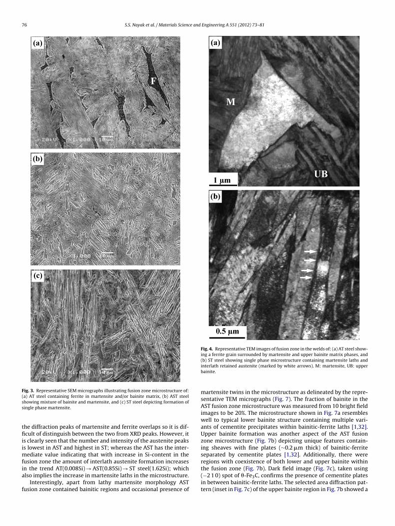
76 S.S. Nayak et al. / Materials Science and Engineering A 551 (2012) 73– 81
Fig. 3. Representative SEM micrographs illustrating fusion zone microstructure of:(a) AT steel containing ferrite in martensite and/or bainite matrix, (b) AST steelss
tfiiimfia
f
Fig. 4. Representative TEM images of fusion zone in the welds of: (a) AT steel show-ing a ferrite grain surrounded by martensite and upper bainite matrix phases, and(b) ST steel showing single phase microstructure containing martensite laths and
howing mixture of bainite and martensite, and (c) ST steel depicting formation ofingle phase martensite.
he diffraction peaks of martensite and ferrite overlaps so it is dif-cult of distinguish between the two from XRD peaks. However, it
s clearly seen that the number and intensity of the austenite peakss lowest in AST and highest in ST; whereas the AST has the inter-
ediate value indicating that with increase in Si-content in theusion zone the amount of interlath austenite formation increasesn the trend AT(0.008Si) → AST(0.85Si) → ST steel(1.62Si); which
lso implies the increase in martensite laths in the microstructure.Interestingly, apart from lathy martensite morphology ASTusion zone contained bainitic regions and occasional presence of
interlath retained austenite (marked by white arrows). M: martensite, UB: upperbainite.
martensite twins in the microstructure as delineated by the repre-sentative TEM micrographs (Fig. 7). The fraction of bainite in theAST fusion zone microstructure was measured from 10 bright fieldimages to be 20%. The microstructure shown in Fig. 7a resembleswell to typical lower bainite structure containing multiple vari-ants of cementite precipitates within bainitic-ferrite laths [1,32].Upper bainite formation was another aspect of the AST fusionzone microstructure (Fig. 7b) depicting unique features contain-ing sheaves with fine plates (∼0.2 �m thick) of bainitic-ferriteseparated by cementite plates [1,32]. Additionally, there wereregions with coexistence of both lower and upper bainite withinthe fusion zone (Fig. 7b). Dark field image (Fig. 7c), taken using
(−2 1 0) spot of �-Fe3C, confirms the presence of cementite platesin between bainitic-ferrite laths. The selected area diffraction pat-tern (inset in Fig. 7c) of the upper bainite region in Fig. 7b showed a
S.S. Nayak et al. / Materials Science and Engineering A 551 (2012) 73– 81 77
F ion zor ionsha
co(r
Fm
ig. 5. Representative TEM images delineating martensite structure in the AST fusetained austenite films, inset is the indexed diffraction pattern showing K–S relatustenite films in (c).
omposite spot pattern demonstrating [1 1 3]�-Fe//[1 2 − 3]�-Fe3Crientation relationship between Fe3C (orthorhombic) and �-Febody centered cubic) phases. Apart from bainite, occasional occur-ence of martensite twins associated with high dislocation density
ig. 6. XRD patterns of the fusion zone of TRIP steels illustrating formation ofartensite (�′) and retained austenite (�).
ne: (a) martensite grains/packets, (b) finer laths, (c) martensite laths separated byip, and (d) dark field image taken using austenite (−2 2 0) confirming the retained
was observed in the mixed-TRIP fusion zone (Fig. 7d) similar toresults reported on LBW of C–Mn–Al TRIP (AT) steel [15]. For-mation of bainitic structure in the fusion zone is attributed toalloying the TRIP steel with Al that accelerates the kinetics of bainiteformation by enhancing nucleation rate [29]. The present observa-tion is corroborated well by earlier reports on formation of bainitein the fusion zone of Al-TRIP steel joined by LBW [14–16]. However,it may be noted that cementite plates observed in upper bainiteregions in the present study were not observed in laser welding ofAl-TRIP steel [15]. This is attributed to combined effort of higher Al(1.73 wt.%) content, compared to 0.65 wt.% in the AST fusion zone,which helps in austenite stabilization by preventing formation ofcarbides [1,2,32] and higher cooling rate in RSW which decreasesthe time allowed for the diffusion of elements into austenite dur-ing the process of bainitic reaction. With the above mentionedresults on microstructural study, it was concluded that fusion zonemicrostructure of AST steel contains various features viz. lathymartensite with interlath retained austenite (Fig. 5), lower bainite(Fig. 7a), upper bainite with cementite plates (Fig. 7b and c) andoccasional presence of martensite twins (Fig. 7d).
3.2. Martensite and retained austenite formation
The microstructure forming in the fusion zone depends on twofactors: cooling rate and chemical composition. In the present

78 S.S. Nayak et al. / Materials Science and Engineering A 551 (2012) 73– 81
Fig. 7. Microstructure of AST steel fusion zone showing: (a) lower bainite, (b) bainitic ferrite laths (bright region) with interlath cementite plates (dark areas), (c) dark fieldimage of (b) taken using �-Fe3C (−2 1 0) spot confirming the cementite plates. The inset in (c) depicts the indexed composite spot patterns of upper bainite region (markedby black arrow) showing [1 2 − 3]�-Fe3C//[1 1 3]�-Fe orientation relationship, (d) martensite twins.
slp(iwfttIAiritptp
oao
tudy, the cooling rate was estimated by simulation to be simi-ar (>3000 K/s, Fig. 2) in all fusion zones considering the weldingarameters were same for all welds; besides, materials typeTRIP780 steel) and thickness (1.0 mm). The simulated cooling raten the fusion zone in the present study was in good agreement
ith that reported by Gould et al. [30]. The critical cooling ratesor the formation of martensite for several AHSS when subjectedo different welding techniques, such as RSW, LBW and resis-ance mesh seam welding (RMSEW) were reported recently [30].n the report, the critical cooling rate for martensite formation forHSS was estimated to be in the range 70–13,500 K/s depend-
ng on the steel chemistry. For TRIP800 steel, the critical coolingate was calculated to be 90 K/s, which is well below the cool-ng rate attained in RSW i.e. >3000 K/s. Thus, in accordance tohe cooling rate TRIP steels subjected to RSW should form singlehase martensite phase in the fusion zone which is contrary tohe observations in the present study as mentioned in foregoingaragraphs.
It is well known that Mn is added to increase the hardenabilityf TRIP steel so that martensite can form easily during fast coolingnd quenching [1,2]. In the present study, due to high concentrationf Mn (>1.6 wt.%) in all the TRIP steels (Table 1) martensite was the
one of the primary microstructural constituents. However, high Mncontent also results in excessive stabilization of retained austenite[1,2,33] which is manifested by the interlath austenite in the fusionzone microstructure (Figs. 4 and 5). In AT fusion zone ferrite wasone of the major phases, the formation of which will be discussedin following section. Another reason for retained austenite in thefusion zone could be the carbon enrichment of austenite [1]. Similarobservation of retained austenite at interlath boundaries wasobserved in the diode laser welds of TRIP steel of similar composi-tion which was reported recently [14–16]. However, the reportsthat austenite is retained within bainitic-ferrite laths stabilizedby sufficient Al-content (1.73 wt.%) during bainitic reaction [1,15].Additionally, the chunk shaped austenite morphology observed inthe fusion zone of laser welded Al-containing TRIP steel [14,15]was not observed in the present study. This can be attributedto the cooling rate in RSW (>3000 K/s) which is high enough toretard significant retained austenite stabilization by inhibiting car-bon diffusion in comparison to cooling rate of 53 K/s in LBW [34]. In
addition, mixing two different steels i.e. AT and ST, in the presentstudy further diminished the chance of blocky retained austeniteformation in AST fusion zone due to chemistry dilution. The above-mentioned discussion indicated that steel chemistry is the only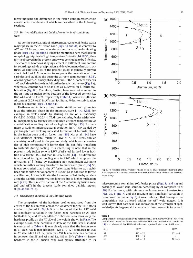
e and Engineering A 551 (2012) 73– 81 79
fcs
3s
mApmfTftacA1wbt0Ai
ieFtamgiacdtptifwilsar((
3
csn(haiiiih
composition was achieved within the AST weld nugget. It iswell known that hardness is an indication of the strength of spot-welded joints. In general, increase in hardness results in increase in
Table 4Comparison of average fusion zone hardness (HV) of the spot welded TRIP steelsstudied with that of the fusion zone in LBW of TRIP steels with similar chemistries[14]. It is to be noted that LBW article has not reported fusion zone of AST steel.
S.S. Nayak et al. / Materials Scienc
actor inducing the difference in the fusion zone microstructureonstituents; the details of which are described in the followingections.
.3. Ferrite stabilization and bainite formation in Al-containingteel
As per the observations of microstructure, skeletal ferrite was aajor phase in the AT fusion zone (Figs. 3a and 4a) in contrast toST and ST fusion zones wherein martensite was the dominatinghase (Figs. 3b, c, 4b, and 5). It may be mentioned here that skeletalorphology is typical of high temperature �-ferrite [14,18,35], thus
errite observed in the present study was concluded to be �-ferrite.he choice of Al or Si as alloying element in TRIP steel is importantor retarding carbide precipitation and development of microstruc-ures. Al-TRIP steel, as in the present study, is generally alloyedbout 1–1.3 wt.% Al in order to suppress the formation of ironarbides and stabilize the austenite at room temperature [18,35].ccording to Fe–Al binary phase diagram, if the Al content exceeds.05 wt.% than �-ferrite is stabilized in the microstructure (Fig. 8a);hereas Si content has to be as high as 1.95 wt.% for �-ferrite sta-
ilization (Fig. 8b). Therefore, ferrite phase was not observed inhe AST and ST fusion zones because of the lower Al-content i.e..65 wt.% and 0.03 wt.%, respectively (Table 1); whereas sufficientl content (1.27 wt.%) in AT steel facilitated �-ferrite stabilization
n the fusion zone (Figs. 3a and 4a).Furthermore, Al is a strong ferrite stabilizer and promotes
t as the primary phase in the microstructure [1,14,18,35]. Forxample, in welds made by striking an arc on a stationarye–0.23C–0.56Mn–0.26Si–1.77Al steel cylinder, ferrite with skele-al morphology (�-ferrite) was stabilized at room temperature at
solidification cooling rate of as high as 103 K/s [35]. Further-ore, a study on microstructural evolution in Al-TRIP welded by
as tungsten arc welding indicated formation of �-ferrite phasen the fusion zone and at fusion line [18]. Xia et al. [14] havelso identified skeletal ferrite in LBW of Al-TRIP steel, similarhemistry as AT steel in the present study, which was a remain-er of high temperature �-ferrite that did not fully transformo austenite during cooling. It is interesting to note that in theresent study fusion zone in RSW of AT steel formed lower frac-ion of �-ferrite (15 ± 3%) than in LBW (30%) [14]. This differences attributed to higher cooling rate in RSW which suppress theormation of �-ferrite by stabilizing non-equilibrium austenitehich on further cooling transforms to martensite phase [35]. So,
t was concluded that in the AT fusion zone �-ferrite was stabi-ized due to sufficient Al-content (>1.05 wt.%). In addition to ferritetabilization, Al also facilitates the formation of bainite by acceler-ting the bainitic transformation kinetics due to higher nucleationate [2,29]. Thus, microstructure of the Al-containing fusion zoneAT and AST) in the present study contained bainitic regionsFigs. 4a and 7a–c).
.4. Fusion zone hardness of the TRIP steel welds
The comparison of the hardness profiles measured from theenter of the fusion zone across the weldment for the TRIP steelstudied is plotted in Fig. 9. It is to be noted that for AST weldo significant variation in the fusion zone hardness on AT side460–495 HV) and ST side (485–510 HV) was seen, thus, only theardness profile on the AT side of the weld is shown in Fig. 9. Theverage fusion zone hardness in RSW of the TRIP steels studieds compared in Table 4. It was clearly seen that the fusion zone
n ST steel has higher hardness (526 ± 10 HV) compared to thatn AT steel (425 ± 22 HV); whereas AST fusion zone has hardnessn between the ST and AT steel i.e. 486 ± 15HV (Table 4). Lowerardness in the AT fusion zone was mainly attributed to itsFig. 8. Fe-rich side of binary (a) Fe–Al and (b) Fe–Si phase diagram illustrating that�-ferrite phase is stabilized in steel if Al or Si content exceeds 1.05 wt.% or 1.95 wt.%,respectively.
microstructure containing soft ferrite phase (Figs. 3a and 4a) andpossibly to lower solid solution hardening by Al compared to Si[36]. Furthermore, with reference to fusion zone microstructure(Figs. 3b, 5 and 7) and the resultant not significant variation infusion zone hardness (Fig. 9), it was confirmed that homogeneous
Steel RSW LBW
AT 425 ± 22 331 ± 4AST 486 ± 15 –ST 526 ± 10 484 ± 5

80 S.S. Nayak et al. / Materials Science and
Fig. 9. Hardness profiles of the weldments in all the TRIP steels studied; where FZ:f
soo(cai
rrtiftFts(acbprtmitfoLzaRdL
4
aaF
[
[
[
[
[[
[[[
[
[
[341.
[22] S. Brauser, L.A. Pepke, G. Weber, M. Rethmeier, Mater. Sci. Eng. A 527 (2010)
usion zone, HAZ: heat affected zone, and BM: base metal.
trength whereas decreasing formability or ductility. The hardnessf the ST steel fusion zone is appreciably higher as a consequencef the single phase microstructure comprising lathy martensiteFigs. 3c and 4b) in comparison to the AT steel fusion zone whichontains mixed microstructure containing softer phases like ferritend bainite along with martensite (Figs. 3a and 4a); this results isn good agreement with the earlier reports [17,36–38].
To analyze the effect of cooling rate on fusion zone hardness,esults of TRIP steels with similar chemistries welded in LBWeported by Xia et al. [14] are also enlisted in Table 4. It is seenhat the fusion zone hardness increased from AT to ST steel whichmplies decrease in Al content or increase in Si content in theusion zone (Table 1). The hardness change with Al and Si con-ent was promptly correlated to the corresponding microstructure.or example, AT steel (1.27Al–0.08Si) forming soft ferrite phase inhe fusion zone (Figs. 3a and 4a) leads to lower hardness and STteel (0.03Al–1.62Si) containing fully martensitic microstructureFigs. 3c and 4b) had higher hardness; whereas AST steel has Alnd Si content (Table 1) lying in between AT and ST steel thus indi-ated hardness in between the respective fusion zone as confirmedy the mixed microstructure containing martensite and bainitehase (Figs. 3b, 5, and 7). Furthermore, it was also seen that RSWesulted in higher fusion zone hardness overall which is attributedo the very high cooling rate in RSW (>3000 K/s) as can be esti-
ated from Fig. 2, compared to moderate cooling rate of 53 K/sn LBW [15,38] which facilitates formation of different microstruc-ural constituents in the fusion zone. For instance, if we compare ATusion zone higher hardness was observed in RSW due to formationf lower fraction (15 ± 3%) of soft ferrite phase (Fig. 3a) compared toBW (30%) [14]. However, as no other phase was found in ST fusionone in both RSW and LBW [14] apart from martensite structurend the carbon content in the steel was same, it was concluded thatSW of ST steel resulted in finer grains/packets of martensite phaseue to faster cooling leading to the higher hardness compared toBW.
. Conclusions
Fusion zones of TRIP steels in resistance spot welding were char-
cterized, with respect to fusion zone microstructure and hardness,nd compared with the results of laser welding of similar steels.ollowing conclusions were drawn from the study:[
Engineering A 551 (2012) 73– 81
1. Fusion zone microstructure was dependent on its chemistry: (i)AT steel formed mixture of ferrite (15%) along with bainite andmartensite, (ii) AST fusion zone contained mostly martensitewith few regions of upper and lower bainite (20%) accompa-nied by occasional martensite twins, (iii) whereas ST fusion zonecontains single phase martensite structure.
2. Martensite phase observed was lath structure with stabilizationof interlath austenite; the fraction of which was observed toincrease with increase in Si-content in the fusion zone.
3. An increase in average fusion zone hardness with decreasein Al content or increase in Si-content was observed; whichwas attributed to increasing fraction of hard martensitephase and decrease in soft ferrite fraction in the microstruc-ture. Accordingly, hardness of the fusion zone followed thetrend: AT (425 ± 22 HV) → AST steel (486 ± 15 HV) → ST steel(526 ± 10 HV).
4. Effect of cooling rate on the hardness of the fusion zone sug-gested that higher cooling rate (>3000 K/s) in RSW leads to higherhardness compared to LBW with moderate cooling rate (53 K/s),irrespective of the steel chemistry, due to decrease in softerferrite phase (AT steel) in the microstructure or refinement ofmartensite grains/packets (ST steel).
Acknowledgments
The authors would like to acknowledge the financial supportfrom Auto21, one of the Networks of Centres for Excellence sup-ported by the Government of Canada, The Initiative for AutomotiveManufacturing Innovation (IAMI) supported by the Ontario Gov-ernment, ArcelorMittal Dofasco Inc., Hamilton, Canada. Authorsare thankful to Prof. S. Haro Rodriguez for his help in carryingout the XRD study at MPyM-EPMM Academic Unit of Engineering,Autonomous University of Zacatecas, Mexico.
References
[1] H. Bhadeshia, R. Honeycombe, Steels: Microstructure and Properties, third ed.,Butterworth-Heinemann, Oxford, UK, 2006.
[2] B.C. De Cooman, Curr. Opin. Solid State Mater. Sci. 8 (2004) 285.[3] V.F. Zackay, E.R. Parker, R. Busch, Trans. ASM 60 (1967) 252.[4] S. Zaefferer, J. Ohlert, W. Bleck, Acta Mater. 52 (2004) 2765.[5] P.J. Jacques, Curr. Opin. Solid State Mater. Sci. 8 (2004) 259.[6] H.K.D.H. Bhadesia, ISIJ Int. 42 (2002) 1059.[7] J. Maki, J. Mahieu, B.C. De Cooman, Proc. 5th Int. Conf. on Zinc and Zinc Alloy
Coated Steel Sheet (Galvatech 2001), Centre de Researches Meâtallurgiques,Bruxelles, Belgium, 2001.
[8] E. Giraulta, A. Mertensb, P. Jacquesb, Y. Houbaertc, B. Verlindena, J.V. Hum-beecka, Scr. Mater. 44 (2001) 885.
[9] P.J. Jacques, E. Girault, P. Harlet, F. Delannay, ISIJ Int. 41 (2001) 1061.10] Committee on Automotive Applications, AHSS – Application Guidelines, Inter-
national Iron and Steel Institute, Washington, DC, 2006.11] V.H. Baltazar Hernandez, M.L. Kuntz, M.I. Khan, Y. Zhou, Sci. Technol. Weld.
Joining 13 (2008) 769.12] S. Daneshpour, S. Riekehr, M. Kocak, V. Ventzke, A.I. Koruk, Sci. Technol. Weld.
Joining 12 (2007) 508.13] T.K. Han, S.S. Park, K.H. Kim, C.Y. Kang, I.S. Woo, J.B. Lee, ISIJ Int. 45 (2005)
60.14] M. Xia, Z. Tian, L. Zhao, Y.N. Zhou, ISIJ Int. 48 (2008) 483.15] J. Chen, K. Sand, M.S. Xia, C. Ophus, R. Mohammadi, M.L. Kuntz, Y. Zhou, D.
Mitlin, Metall. Mater. Trans. A 39A (2008) 593.16] M. Xia, Z. Tian, L. Zhao, Y.N. Zhou, Mater. Trans. JIM 49 (2008) 746.17] M.I. Khan, L.M. Kuntz, Y. Zhou, Sci. Technol. Weld. Joining 13 (2008) 294.18] M. Amrithalingam, M. Hermans, I. Richardson, Metall. Mater. Trans. A 40A
(2009) 901.19] C. Ma, D.L. Chen, S.D. Bhole, G. Boudreau, A. Lee, E. Biro, Mater. Sci. Eng. A 485
(2008) 334.20] H. Ghazanfari, M. Naderi, M. Iranmanesh, M. Seydi, A. Poshteban, Mater. Sci.
Eng. A 534 (2012) 90.21] X. Liao, X. Wang, Z. Guo, M. Wang, Y. Wu, Y. Rong, Mater. Character. 61 (2010)
7099.23] C. Liu, Z. Zhao, D.O. Northwood, Y. Liu, J. Mater. Process. Technol. 113 (2001)
556.

e and
[
[
[
[[[[[
[
[[[
[
S.S. Nayak et al. / Materials Scienc
24] Resistance Welding Manufacturing Alliance (RWMA), /(accessed on10.11.2011).
25] ANSI/AWS/SAE D8.9-97, Recommended Practices for Test Methods for Evaluat-ing the Resistance Spot Welding Behavior of Automotive Sheet Steels Materials,American Welding Society, Miami, 1997.
26] B.L. Bramfitt, A.O. Benscoter, Metallographer’s Guide: Practices and Proceduresfor Irons and Steels, first ed., ASM International, 2002.
27] http://www.rccm.co.jp/seihin/quickspot/index.html (accessed on 13.11.2011).28] V.H. Baltazar Hernandez, Y. Okita, Y. Zhou, Weld. J., in press.29] C. Garcia-Mateo, F.G. Caballero, H.K.D.H. Bhadesia, ISIJ Int. 43 (2003) 1821.30] J.E. Gould, S.P. Khurana, T. Li, Weld. J. 85 (2006) 111s.31] B.V. Narashima Rao, Metall. Trans. A 10A (1979) 645.
[
[
Engineering A 551 (2012) 73– 81 81
32] H.K.D.H. Bhadesia, Bainite in Steels, second ed., The Institute of Materials, Lon-don, 2001.
33] S.J. Kim, C.G. Lee, I. Choi, S. Lee, Metall. Mater. Trans. A 32A (2001) 505.34] O. Akelsen, O. Grong, J. Solberg, Mater. Sci. Technol. 3 (1987) 649.35] S.S. Babu, J.W. Elmer, S.A. David, M.A. Quitana, Proc. R. Soc. (London) 458 (2002)
811.36] P.A. Manohar, K. Kunishige, T. Chandra, M. Ferry, Mater. Sci. Technol. 118 (2002)
856.37] P.J. Jacques, E. Girault, A. Mertens, B. Verlinden, J. Van Humbeeck, F. Delannay,
ISIJ Int. 41 (2001) 1068.38] M. Pouranvari, H.R. Asgari, S.M. Mosavizadch, P.H. Marashi, M. Goodarzi, Sci.
Technol. Weld. Joining 12 (2007) 217.