material testing lab manual
DESCRIPTION
Material Testinglaboratory testing allTRANSCRIPT

Faculty of Engineering Islamic University of Gaza
Materials & Soil Labs Civil Engineering Department
Building Materials Laboratory Manual
Prepared by:
Eng. A.Al Kourd Eng. Adel Hammad
2009/2010

Aggregate Testing

Building Materials Laboratory Manual Fall 2007-2008
Prepared by: B. J. Farid 4
How to write a laboratory report
The following arrangement of the report is suggested:
This should indicate the nature of the test and the specifications Title number used.
A brief statement of the purpose and significance Scope of the test :of the test should be indicated.
d. ed or tested should be describeThe materials usMaterials :
Special equipment used should Apparatus and method of testing:be briefly described. The testing procedure should be also described.
mitted All laboratory data shall be sub : Data and results of the testin tabular form. Observations relating to the behavior of the materials
should be included. All equations or formulas used should be clearly
indicated. Calculations should be properly checked. The results of the test
should be summarized in tabular or graphical form.
There should be included a brief discussion in which Discussion attention is drawn to the silent facts shown by the tables and diagrams.
The test results should be compared with the standard values and
conclusion should be drawn.
Building Materials Laboratory Manual Fall 2007-2008
Prepared by: B. J. Farid 2
Reducing Field Sample of Aggregate to Test Sample
ASTM C 702, D75
Purpose: To obtain laboratory samples of aggregates from stockpiles.
Equipment: Shovel, scoop , boom.
Procedure: 1-Obtain a sample of aggregate (about 50 kg) from three places in the
stockpile: from the top third, at the midpoint, and from the bottom third
of the volume of the pile.
2- Place the field sample on a hard, clean level surface.
3- Mix the material thoroughly by turning the entire sample three times.
4- Shovel the entire sample into a conical pile.
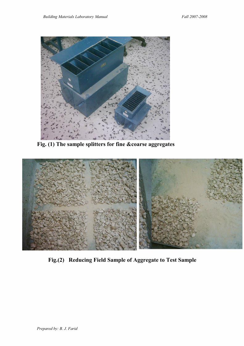
5- Carefully flatten the conical to a uniform thickness and diameter by
pressing down the apex with a shovel. ( The diameter should be
approximately four to eight times the thickness).
6- Divide the flattened mass into four equal quarters with a shovel.
7- Remove two diagonally opposite quarters. Brush the cleared spaces
clean.
8-Mix and quarter the remaining materials until the sample is reduced to
the desired size.
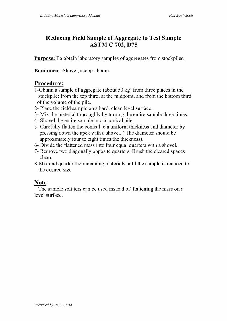
Note The sample splitters can be used instead of flattening the mass on a
level surface.
Building Materials Laboratory Manual Fall 2007-2008
Prepared by: B. J. Farid 3
Fig. (1) The sample splitters for fine &coarse aggregates
Fig.(2) Reducing Field Sample of Aggregate to Test Sample
Building Materials Laboratory Manual Fall 2007-2008
Prepared by: B. J. Farid 5
Test No.1:
“Moisture Content of Concrete Aggregate” ( ASTM C-566- 84)
Scope of test:
One of the properties of the aggregates which should be known to design a
concrete mix is its moisture content. It is necessary in order to determine the net
water -cement ratio in a batch of concrete made with job aggregate.
Materials:
The amount of materials depends on the nominal maximum size of aggregate as
follows:
Weight of Sample N.M.S
g)k( (mm)
0.5 4.75
1.5 9.5
2 12.5
3 19
4 25
6 37.5
Apparatus: 1. A balance sensitive to 0.5gm.
2. Electrical oven at temperature 105 °C.
3. Container with a cover. 4. Sample splitter.
Procedure:
1- Prepare the container clean, record its empty weight (A).
2- Weigh the suitable sample of aggregate and keep it in a container, put the cover on.
3-The weight of the container with the cover and the gravel is (B).
4-Remove the cover, then put the sample in the oven at 105 °C for 24 hours.
5-Remove the sample forms the oven and put the cover on it, then leaves it for half
Building Materials Laboratory Manual Fall 2007-2008
Prepared by: B. J. Farid 6
an hour, and then weigh it (D).
6- Repeat the same steps for the sand sample.
Calculations and Results:
Moisture Content % = [ ( B – D ) / ( D – A )] x 100
Discussion: 1- Comment on the results you get.
2- Do you think that your results are affected by the weather conditions?
Building Materials Laboratory Manual Fall 2007-2008
Prepared by: B. J. Farid 7
Test 2:
“Specific Gravity and Absorption of Coarse Aggregate”
(ASTM C 127 – 88)
Scope:
This test method covers the determination of Specific Gravity and Absorption
of coarse aggregate. The specific gravity may be expressed as bulk specific gravity,
bulk specific gravity SSD or apparent specific gravity. The bulk specific gravity and
absorption are based on aggregate after 24hour soaking in water.
Materials:
1- Coarse aggregate , must be sampled using sample splitter.
2- The weight of the sample depends on nominal maximum size (NMS) of the
aggregate as follows.
Minimum Weight of Sample N.M.S
g)k( (mm)
12.5 or less 2
3 19
4 25
5 37.5
8 50
: Apparatus 1-A weighing balance sensitive, readable and accurate to 0.5gm.
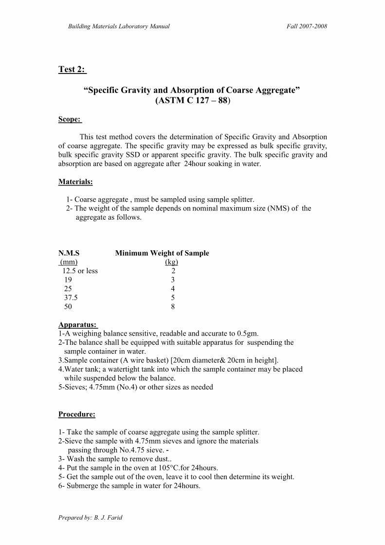
2-The balance shall be equipped with suitable apparatus for suspending the
sample container in water.
3.Sample container (A wire basket) [20cm diameter& 20cm in height].
4.Water tank; a watertight tank into which the sample container may be placed
while suspended below the balance.
5-Sieves; 4.75mm (No.4) or other sizes as needed
Procedure:
1- Take the sample of coarse aggregate using the sample splitter.
2-Sieve the sample with 4.75mm sieves and ignore the materials
passing through No.4.75 sieve. - 3- Wash the sample to remove dust..
4- Put the sample in the oven at 105°C.for 24hours.
5- Get the sample out of the oven, leave it to cool then determine its weight.
6- Submerge the sample in water for 24hours.

Building Materials Laboratory Manual Fall 2007-2008
Prepared by: B. J. Farid 8
7- Remove the sample from the water and roll it in a large absorbent cloth until all
visible films of water are removed .Wipe the larger particles individually. Take
care to avoid evaporation of water from aggregate pores during the operation
of surface- drying.
8- Take the required weight of the sample in its (S.S.D) (saturated surface dry)
condition.
9-After weighing ,immediately place the S.S.D sample in the sample container
and determine its weight in water at 23±1°C.Take care to remove all entrapped a
before weighing by shaking the container while immersed.
10-Dry the test sample to constant weight at a temperature of 110±5°C, Cool in air
at room temperature 1 to 3 hours, or until the aggregate has cooled to a temperature
that is comfortable to handle, and weigh.
Calculations :-
1-Specific Gravity:-
a. Bulk specific gravity: - Calculate the bulk specific gravity as follow :
Bulk Specific Gravity = A /(B-C)
Where:
A=Weight of oven-dry test sample in air,(gm).
B= Weight of S.S.D. sample in air,(gm).
C=Weight of saturated sample in water,(gm).
b- Bulk Specific Gravity (SSD) = B / (B-C)
c-Apparent Specific gravity: - Calculate the apparent sp. gr. As follows:
Apparent Specific Gravity = A / (A - C)
2- Absorption:-
Calculate the percentage of absorption as follows:
Absorption% = [(B – A) / A ]x100
Discussion:
1-Comment on the results. 2- Compare the results with the typical values.
3- How can the percentage of absorption affect on a concrete mix?
Building Materials Laboratory Manual Fall 2007-2008
Prepared by: B. J. Farid 9
Fig.(3) A balance with suitable apparatus for suspending the sample
container in water.
Building Materials Laboratory Manual Fall 2007-2008
Prepared by: B. J. Farid 10
Test No.3
“Specific Gravity and Absorption of fine Aggregate”
(ASTM C 127 – 88)
Scope:. This test method covers the determination of Bulk and Apparent Specific
Gravity and Absorption of fine aggregate.
Materials:- l kg of sand is used using sample splitter.
Apparatus:
1-A balance having capacity of 1kg or more sensitive to 0.1gm
2- Pycnometer: A flask or other suitable container into which the fine
aggregate
sample can be introduced .It is
usually of 500cm3 capacity.
3-Mold: a metal mold in the form of a frustum of a cone with dimensions as follows:
37mm inside diameter at the top, 90mm inside diameter at the bottom and 75mm
in height.
4-Tamper: A metal tamper weighing 340±15gm and having a flat circular tamping
face 25mm in diameter.
5- Electrical Oven.
6- A container suitable to submerge the sample with water.
Preparation of the test Specimen:- 1-Obtain approximately 1kg of the fine aggregate using sample splitter.
2- Dry it in a suitable pan or vessel to constant weight at 110°C. Allow it to cool to a
comfortable handling temperature, cover with water by immersion and permit to
stand for 24 hours.
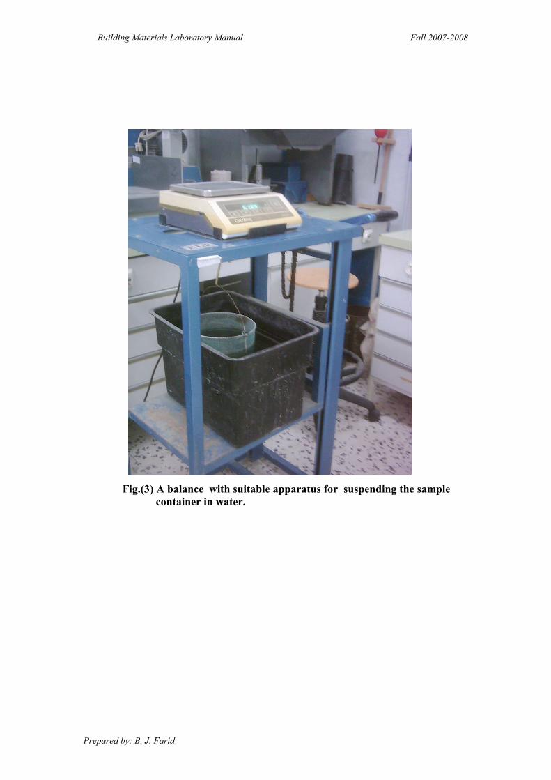
3- Decant excess water with care to avoid loss of fines, spread the sample on a flat
nonabsorbent surface exposed to a gently moving current of warm air.
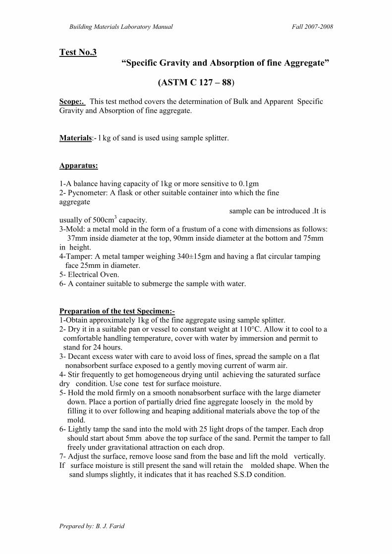
4- Stir frequently to get homogeneous drying until achieving the saturated surface
dry condition. Use cone test for surface moisture.
5- Hold the mold firmly on a smooth nonabsorbent surface with the large diameter
down. Place a portion of partially dried fine aggregate loosely in the mold by
filling it to over following and heaping additional materials above the top of the
mold.
6- Lightly tamp the sand into the mold with 25 light drops of the tamper. Each drop
should start about 5mm above the top surface of the sand. Permit the tamper to fall
freely under gravitational attraction on each drop.
7- Adjust the surface, remove loose sand from the base and lift the mold vertically.
If surface moisture is still present the sand will retain the molded shape. When the
sand slumps slightly, it indicates that it has reached S.S.D condition.
Building Materials Laboratory Manual Fall 2007-2008
Prepared by: B. J. Farid 11
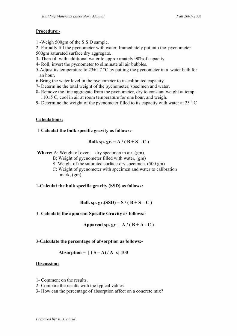
Procedure:-
1 -Weigh 500gm of the S.S.D sample.
2- Partially fill the pycnometer with water. Immediately put into the pycnometer
500gm saturated surface dry aggregate.
3- Then fill with additional water to approximately 90%of capacity.
4- Roll; invert the pycnometer to eliminate all air bubbles.
5-Adjust its temperature to 23±1.7 °C by putting the pycnometer in a water bath for
an hour.
6-Bring the water level in the pycuometer to its calibrated capacity.
7- Determine the total weight of the pycnometer, specimen and water.
8- Remove the fine aggregate from the pycnometer, dry to constant weight at temp.
110±5 C, cool in air at room temperature for one hour, and weigh.
9- Determine the weight of the pycnometer filled to its capacity with water at 23 o C
Calculations:
1-Calculat the bulk specific gravity as follows:-
Bulk sp. gr. = A / ( B + S – C )
Where: A: Weight of oven —dry specimen in air, (gm).
B: Weight of pycnometer filled with water, (gm)
S: Weight of the saturated surface-dry specimen. (500 gm)
C: Weight of pycnometer with specimen and water to calibration
mark, (gm).
1-Calculat the bulk specific gravity (SSD) as follows:
Bulk sp. gr.(SSD) = S / ( B + S – C )
3- Calculate the apparent Specific Gravity as follows:-
Apparent sp. gr=. A / ( B + A - C )
3-Calculate the percentage of absorption as follows:-
Absorption = [ ( S – A) / A x] 100
Discussion:
1- Comment on the results.
2- Compare the results with the typical values.
3- How can the percentage of absorption affect on a concrete mix?

Building Materials Laboratory Manual Fall 2007-2008
Prepared by: B. J. Farid 12
Fig.(4) Exposing the
fine aggregate to a
gently moving
current of warm air.
Fig.(5) The fine aggregate is still damp. Fig.(6) The fine aggregate is
in SSD condition.
Building Materials Laboratory Manual Fall 2007-2008
Prepared by: B. J. Farid 13
Test No.4
“Resistance to Degradation of Small-size coarse Aggregate
by Abrasion in the Los Angeles Machine.”
ASTM C 131-81(1987)
Scope of test: This test method cover testing sizes of coarse of (12.5mm)
for resistance to degradation using the Los Angeles testing machine.
Summary of test:
The Los Angeles test is a measure of degradation of mineral aggregates of
standard grading resulting form a combination of actions including abrasion or
attrition, impact, and grinding in a rotating steel drum containing a specified number
of steel spheres, the number depending upon the grading of the test sample. As the
drum rotates a shelf plate picks up the sample and the steel spheres, carrying them
around until they are dropped to the opposite side of the drum, creating an impact-
crushing effect. The contents then roll within thedm with an abrading and grinding
action until the shelf plate impacts and the cycle is repeated. After the prescribed
number of revolutions, the content is removed from the drum and the aggregate
portion is sieved to measure the degradation as percent loss.
Materials:
The test sample shall be washed and oven-dried at (105-110) CO and
separated into individual size fractions and recombined to the grading of table (1)
most nearly corresponding to the range of sizes in the aggregate as furnished for the
work.
Apparatus:-
1. Los Angeles Machine.
2. Sieves.
3. Balance accurate to 0.5 gm.
4. Oven. And containers.
5. Charge – The Charge must consist of steel spheres averaging (46.8mm) in
diameter and each weighing between 390 to 445gm. The charge, depending upon
the grading of the test sample as follows:

Building Materials Laboratory Manual Fall 2007-2008
Prepared by: B. J. Farid 14
Grading No: of spheres Wt of charge (gm)
A 12 5000+25
B 11 4584+25
C 8 3330+20
D 6 2500+15
Procedure:
1. Put the sample of coarse aggregate in an oven at 105°C to get oven-dry sample.
2. Prepare the sample, then Weigh and record its weight to the nearest 1gm.
3.Placc the test sample and charge in the Los Angeles testing
machine and rotate the machine at 30to33 round/mm for 500
revolutions.
4. Discharge the material from the machine and make preliminary separation of the
sample a sieve coarser then (1.7mm).The finer portion shall then be sieved on a
1.7mm sieve.
5. The material coarser then the 1.7mm sieve shall be washed, oven dried at 105 oC
to substantially constant weight, and weighed to
the nearest 5gm.
Calculations:
%Abrasion = wt of the initial sample- wt of retained of 1.7mm sieve x 100
Wt of initial sample
Or = wt of passing sieve (1.7mm) x 100 wt. of initial sample
Note:
ASTM Specifications C33-86 requires that the abrasion percent should not exceed
50% for coarse aggregate used in concrete mixes.
Building Materials Laboratory Manual Fall 2007-2008
Prepared by: B. J. Farid 15
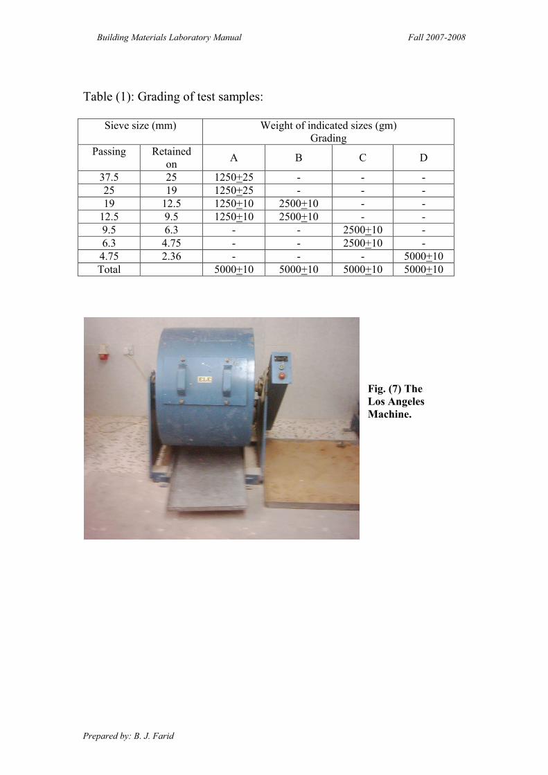
Table (1): Grading of test samples:
Weight of indicated sizes (gm)
Grading
Sieve size (mm)
D C B A Retained
on
Passing
- - - 25+1250 25 37.5
- - - 25+1250 19 25
- - 10+2500 10+1250 12.5 19
- - 10+2500 10+1250 9.5 12.5
- 10+2500 - - 6.3 9.5
- 10+2500 - - 4.75 6.3
10+5000 - - - 2.36 4.75
10+5000 10+0050 10+0500 10+5000 Total
Fig. (7) The
Los Angeles
Machine.
2 Building Materials Testing Laboratory 2009/2010
AGGREGATE CRUSHING STRENGTH TEST Theory and Scope:
This is one of the major Mechanical properties required in a road stone. The test
evaluates the ability of the Aggregates used in road construction to withstand the stresses
induced by moving vehicles in the form of crushing. With this the aggregates should also
provide sufficient resistance to crushing under the roller during construction and under rigid
tyre rims of heavily loaded animal drawn vehicles.
The crushing strength or aggregate crushing value of a given road aggregate is found
out as per IS-2386 Part- 4.
The aggregate crushing value provides a relative measure of resistance to crushing
under a gradually applied compressive load. To achieve a high quality of pavement aggregate
possessing low aggregate crushing value should be preferred.
The aggregate crushing value of the coarse aggregates used for cement concrete
pavement at surface should not exceed 30% and aggregates used for concrete other than for
wearing surfaces, shall not exceed 45% as specified by Indian Standard (IS) and Indian Road
Congress (IRC).
Aim: To determine crushing strength of a given aggregate as per IS: 2386 part - IV
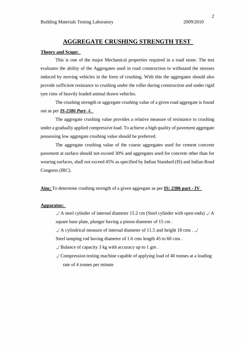
Apparatus: .,/ A steel cylinder of internal diameter 15.2 cm (Steel cylinder with open ends) .,/ A
square base plate, plunger having a piston diameter of 15 cm .
.,/ A cylindrical measure of internal diameter of 11.5 and height 18 cms . .,/
Steel tamping rod having diameter of 1.6 cms length 45 to 60 cms .
.,/ Balance of capacity 3 kg with accuracy up to 1 gm .
.,/ Compression testing machine capable of applying load of 40 tonnes at a loading
rate of 4 tonnes per minute

3 Concrete and Highway Materials Testing Laboratory
Procedure:
~ The aggregate in surface-dry condition before testing and passing 12.5 mm sieve
and retained on 10 mm sieve is selected.
~ The cylindrical measure is filled by the test sample of the aggregate in three layers
of approximately equal depth, each layer being tamped 25 times by the rounded
end of the tamping rod.
~ After the third layer is tamped, the aggregates at the top of the cylindrical measure
are leveled off by using the tamping rod as a straight edge. Then the test sample is
weighed. Let that be WI gm.
~ Then the cylinder of test apparatus is kept on the base plate and one third of the
sample from cylindrical measure is transferred into cylinder and tamped 25 times
by rounded end of the tamping rod.
~ Similarly aggregate in three layers of approximately equal depth, each layer being
tamped 25 times by rounded end of the tamping rod.
~ Then the cylinder with test sample and plunger in position is placed on
compression testing machine.
~ Load is then applied through the plunger at a uniform rate of 4 tonnes per minute
until the total load is 40 tonnes and the load is released.
~ Aggregates including the crushed position are removed from the cylinder and
sieved on a 2.36mm IS. sieve and material which passes this sieve is collected
and weighed. Let this be W2 gm.
~ The above step is repeated with second sample of the same aggregate. The two
tests are made for the same specimen for taking an average value.
~ Total weight of dry sample taken is WI gm weight of the portion of crushed
material passing 2.36mm IS sieve be W2 gm.
Then the aggregate crushing value is defined as the ratio of weight of fines
passing the specified IS sieve to the total weight of the sample (WI).
Aggregate crushing value = 100*W2/WI%

Aggregate Crushing Test Apparatus
Crushing Test in Progress

5 Concrete and Highway Materials Testing Laboratory
Observation and Calculation:
Total weight Weight of fines Aggregate Average aggregate of dry passing Trials crushing value crushing strength aggregate 2.36mm IS % value sample 10 gm sieve, w2gm
1
2
Aggregate crushing value = 100*W2/Wl.
Result:
The mean (average) of the crushing value aggregate is ______________________ %
Viva voce:
1. What do you understand by the term "Ten percent Fines value"?

6 Concrete and Highway Materials Testing Laboratory
2. Define aggregate crushing value and how crushing strength test is carried out on
cylindrical stone specimen explain.
3. What is the use or application of the aggregate crushing test?
Reference:
2. Indian Standard Methods of Test for Aggregate for concrete IS: 2386 Part-IV, Indian
Standards Institution.
3. Indian Standard Specifications for Coarse and Fine Aggregate from Natural Sources
for Concrete, IS: 383 Indian Standards Institution.
4. S.K. Khanna, C.E.G. Justo, Highway Material Testing Laboratory Manual, Nem
Chand & Bros., Roorkee.

8 9
Concrete and Highway Materials Testing Laboratory
ABRASION TEST
Theory and Scope:
Abrasion is a measure of resistance to wear or hardness. It is an essentially property for road
aggregates especially when used in wearing coarse. Due to the movements of traffic, the road
stones used in the surfacing course are subjected to wearing actions at the top. When traffic
moves on the road the soil particle (sand) which comes between the wheel and road surface
causes abrasion on the road stone. The abrasion test on
aggregate is found as per I.S.-2386 part-IV.
Abrasion tests on aggregates are generally carried out by anyone of the following
methods-
1. Los Angeles abrasion test.
2. Deval abrasion test.
3. Dorry abrasion test.
Los An2eles Abrasion Test: - The principle of Los Angeles abrasion test is to find the
percentage wear due to the relative rubbing action between the aggregates and steel balls
used as abrasive charge pounding action of these balls also exist while conducting the test.
Maximum Allowable Los Angeles Abrasion Values of Aggregates in Different types of
pavement layers as per Indian Road Congress (IRC) are:-
For sub-base course a value of 60%. For base course such as WBM, Bituminous
Macadam (B.M.), Built - Up spray grout base course and etc. value of 50%.
For surface course such as WBM, BM, Bituminous Penetration Macadam, Built-Up
spray grout binder course and etc. a value of 40%.
If aggregates are used in surface course as Bituminous carpet, Bituminous surface
dressing, single or two coats, cement concrete surface coarse and etc. a value of 35%.

10 Concrete and Highway Materials Testing Laboratory
If aggregates are used for Bituminous concrete, Cement concrete pavement as
surface coarse than aggregate abrasion value of 30% maximum.
Aim: To determine the abrasion value of given aggregate sample by conducting Los Angeles
abrasion Test.
Apparatus: 1/' Los Angeles machine with inside diameter 70cm and inside length of
50%.Abrasive charges.
1/' L S Sieve with 1.7mm opening.
1/' Weighting Balance ofO.1gm accuracy.
Procedure:
~ Clean and dry aggregate sample confirming to one of the grading A to G is used for
the test. (Refer table no. 1)
~ Aggregates weighing 5Kg for grading A, B, C or D and 10Kg for gradings E, F or
G may be taken as test specimen and placed in the cylinder.
~ The abrasive charge is also chosen in accordance with table no. 1 and placed in the
cylinder of the machine, and cover is fixed to make dust tight.
~ The machine is rotated at a speed of30 to 33 revolutions per minute.
~ The machine is rotated for 500 revolutions for gradings A, B, C and D, for gradings
E, F and G, it shall be rotated for 1000 revolutions.
~ After the desired number of revolutions, the machine is stopped and the material is
discharged from the machine taking care to take out entire stone dust.
~ Using a sieve of size larger than 1.70mm LS sieve, the material is first separated
into two parts and the finer position is taken out and sieved further on a 1.7mm L
S sieve.
~ Let the original weight of aggregate be Wlgm, weight of aggregate retained on
1.70mm L S sieve after the test be W2gm.
11 Concrete and Highway Materials Testing Laboratory
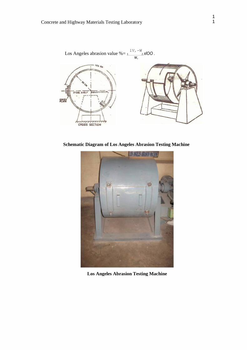
lV,-W Los Angeles abrasion value %= 1 2 xlOO .
w,
Schematic Diagram of Los Angeles Abrasion Testing Machine
Los Angeles Abrasion Testing Machine

12 Concrete and Highway Materials Testing Laboratory
Observation and Calculation:
Sl. Details of Sample Trail 1 Trail 2 Average No.
1 Weight of Specimen = WIg
2 Weight of Specimen after abrasion test, coarser
thanl. 70 mm IS sieve = W 2 g
3 Percentage wear = «WI- W2) I WI) * 100

13 Concrete and Highway Materials Testing Laboratory
TABLE NO.1
Weight in grams of each test sample in the size range, mm (passing and retained on Square Abrasive Charge. ~ holes) = ...• -= = No. of Weight of "'" CJ 80-63 63-50 50-40 40-25 25-20 20-12.5 12.5-10 10-6.3 6.3-4.75 4.75-2.36
Spheres charge, g
A - - - 1250 1250 1250 1250 - - - 12 5000± 25
B - - - - - 2500 2500 - - - 11 4584± 25
C - - - - - - - 2500 2500 - 8 3330± 20
D - - - - - - - - - 5000 6 2500± 15
E 2500 2500 5000 - - - - - - - 12 5000± 25
F - - 5000 5000 - - - - - - 12 5000± 25
G - - - 5000 5000 - - - - - 12 5000± 25
14 Concrete and Highway Materials Testing Laboratory
Result:
The average value of two Los Angeles abrasion test is ___________________ %
Viva voce:
1. The abrasion value found from Los Angeles test for two aggregates A and B are 50% and
38% respectively. Which aggregate is harder? Why? For what types of constructions are
these suitable?
2. Why Los Angeles abrasion test is considered superior to the other form of tests which are
used to determine the hardness of aggregates?
3. Two materials have abrasion values 3 and 10 respectively. Which one is harder and why?
Reference:
1. Indian Standard Methods of Test for Aggregate for concrete IS: 2386 Part-IV, Indian
Standards Institution.
2. Indian Standard Specifications for Coarse and Fine Aggregate from Natural Sources for
Concrete, IS: 383 Indian Standards Institution.
3. S.K. Khanna, C.E.G. Justo, Highway Material Testing Laboratory Manual, Nem Chand &
Bros., Roorkee.
17 Concrete and Highway Materials Testing Laboratory
IMPACT TEST Theorv and Scope:
Toughness is the property of a material to easiest impact. Due to moving loads the aggregates
are subjected to pounding action or impact and there is possibility of stones breaking into smaller
pieces. Therefore a test designed to evaluate the toughness of stones i.e., the resistance of the stones to
fracture under repeated impacts may be called Impact test on aggregates. The test can also be carried on
cylindrical stone specimen known as Page Impact test. The aggregate Impact test has been
standardized by Indian Standard Institution. The aggregate impact test is conducted as per IS-2386 Part
IV.
The aggregate Impact value indicates a relative measure of the resistance of aggregate to a
sudden shock or an Impact, which in some aggregates differs from its resistance to a slope compressive
load in crushing test. A modified Impact test is also often carried out in the case of soft aggregates to
find the wet Impact value after soaking the test sample.
Various agencies have specified the maximum permissible aggregate Impact values for the
different types of pavements. IRC has specified the following values.
The maximum allowable aggregate Impact value for water bound Macadam; Sub-Base coarse
50% where as cement concrete used in base course is 45%. WBM base course with
Bitumen surface in should be 40%. Bituminous Macadam base course should have A.I.V of 35%. All
the surface courses should possess an A.I.V below 30%.
Aim: To determine the aggregate impact value of given aggregate as per I.S-2386 Part IV.
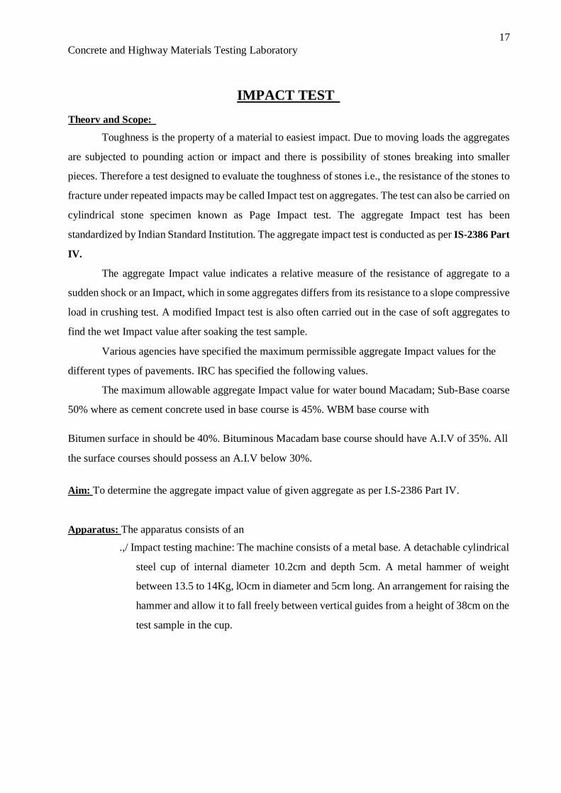
Apparatus: The apparatus consists of an
.,/ Impact testing machine: The machine consists of a metal base. A detachable cylindrical
steel cup of internal diameter 10.2cm and depth 5cm. A metal hammer of weight
between 13.5 to 14Kg, lOcm in diameter and 5cm long. An arrangement for raising the
hammer and allow it to fall freely between vertical guides from a height of 38cm on the
test sample in the cup.

18 Concrete and Highway Materials Testing Laboratory
.,/ A cylindrical metal measure having 7.5cm and depth of 5cm for measuring aggregates .
.,/ A tamping rod of circular cross section, lcm in diameter and 23cm long, rounded at one
end .
.,/ I.S. sieve of sizes 12.5mm, lOmm and 2.36mm .
.,/ Balance of capacity not less than 500gm to weigh accurate up to O.Olgm.
Procedure:
~ The test sample consists of aggregates passing 12.5mm sieve and retained on lOmm sieve
and dried in an oven for 4 hours at a temperature of 100 C to 110 C.
~ The aggregates are filled upto about 1/3 full in the cylindrical measure and tamped 25 times
with rounded end of the tamping rod.
~ The rest of the cylindrical measure is filled by two layers and each layer being tamped 25
times.
~ The overflow of aggregates in cylindrically measure is cut offby tamping rod using it has a
straight edge.
~ Then the entire aggregate sample in a measuring cylinder is weighted nearing to O.Olgm.
~ The aggregates from the cylindrical measure are carefully transferred into the cup which is
firmly fixed in position on the base plate of machine. Then it is tamped 25 times.
~ The hammer is raised until its lower face is 38cm above the upper surface of aggregates in
the cup and allowed to fall freely on the aggregates. The test sample is subjected to a total
of 15 such blows each being delivered at an interval of not less than one second. The
crushed aggregate is than removed from the cup and the whole of it is sieved on 2.366mm
sieve until no significant amount passes. The fraction passing the sieve is weighed accurate
to O.lgm. Repeat the above steps with other fresh sample.

19 Concrete and Highway Materials Testing Laboratory
~ Let the original weight of the oven dry sample be Wlgm and the weight of fraction passing
2.36mm I.S sieve be W2gm. Then aggregate Impact value is expressed as the % of fines
formed in terms of the total weight of the sample.
100 * w Aggregate Impact Value = 2 % .
WI
Aggregate Impact Testing Machine
Observation and Calculation:

20 Concrete and Highway Materials Testing Laboratory
Sl.
Details of Sample Trail 1 Trail 2
Average No.
1 Total Weight of aggregate sample filling the cylinder
measure = WIg
2 Weight of aggregate passing 2.36 mm sieve after the test
=W2g
3 Weight of aggregate retained 2.36 mm sieve after the
test = W 2 g
4 (WI- W2 + W3)
5 Aggregate Impact Value = (W2! WI) * 100 Percent
Result:
The mean A.I.V is %.
Viva voce:
1. How is aggregate Impact expressed?
2. What do you understand by dry and wet Impact value?
3. Aggregate Impact value of material A is 15 and that of B is 35. Which one is better for surface
course?
Reference:
1. Indian Standard Methods of Test for Aggregate for concrete IS: 2386 Part-IV, Indian Standards
Institution.
2. Indian Standard Specifications for Coarse and Fine Aggregate from Natural Sources for Concrete,
IS: 383 Indian Standards Institution.
3. S.K. Khanna, C.E.G. Justo, Highway Material Testing Laboratory Manual, Nem Chand & Bros.,
Roorkee.
23 Concrete and Highway Materials Testing Laboratory
SHAPE TEST (Flakiness Index)
Theorv and Scope: The particle shape of aggregate is determined by the percentages of flaky and elongated
particles contained in it. In case of gravel it is determined by its Angularity Number. Flakiness and
Elongation tests are conducted on coarse aggregates to assess the shape of aggregates. Aggregates
which are flaky or elongated are detrimental to the higher workability and stability of mixes. They are
not conducive to good interlocking and hence the mixes with an excess of such particles are difficult to
compact to the required degree. For base coarse and construction of bituminous and cement concrete
types, the presence of flaky and elongated particles are considered undesirable as they may cause
inherent weakness with probabilities of breaking down under heavy loads. Rounded aggregates are
preferred in cement concrete road construction as the workability of concrete improves. Angular shape
of particles are desirable for granular base coarse due to increased stability derived from the better
interlocking when the shape of aggregates deviates more from the spherical shape, as in the case of
angular, flaky and elongated aggregates, the void content in an aggregate of any specified size increases
and hence the grain size distribution of the graded aggregates has to be suitably altered in order to
obtain minimum voids in the dry mix or the highest dry density. It is determined according to the
procedure laid down in IS-2386 (pART-I).
FLAKINESS INDEX: The flakiness index of aggregates is the percentage by particles whose least
dimension (thickness) is less than 3/Sth (0.6) of their mean dimension. The test is not applicable to sizes
smaller than 6.3mm.
ELONGATION INDEX: The elongation index of an aggregate is the percentage by weight of
particles whose greatest dimension (length) is greater than 1 and 4/Sth times (1.8 times) their mean
dimensions. The elongation test is not applicable to sizes smaller than 6.3mm.
24 Concrete and Highway Materials Testing Laboratory
ANGULARITY NUMBER: The angularity number of an aggregate is the amount by which the percentage
voids exceeds 33 after being compacted in a prescribed manner. The minimum allowable combined index
of aggregates used in surface course in different types of pavement is 30%.
Aim: - To determine the flakiness Index of a given aggregates sample.
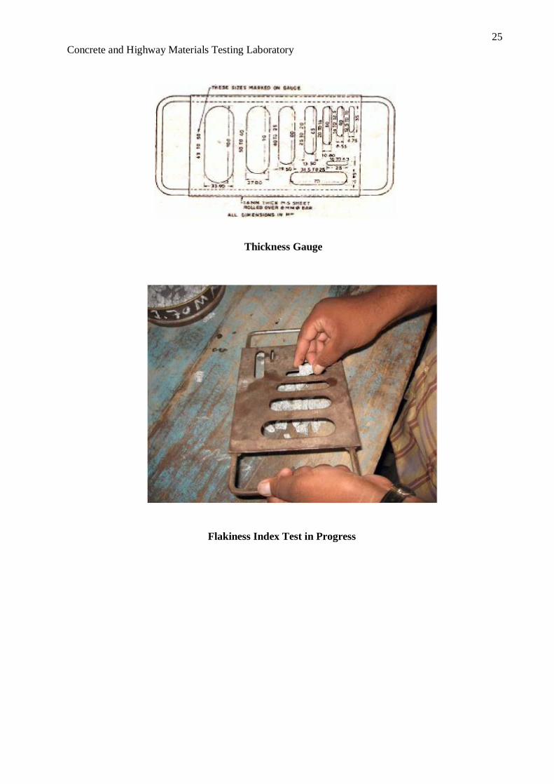
Apparatus: - The apparatus consists of a standard thickness gauge, I.S. sieves of sizes 63, 50,
40,31.5,25,20, 16, 12.5, 10 and 6.3mm and a balance to weigh the samples. Procedure:
~ The sample is sieved with the sieves mentioned in the table.
~ A minimum of 200 pieces of each fraction to be tested are taken and weighed (wlgm).
~ In order to separate flaky materials, each fraction is then gauged for thickness on thickness gauge, or
in bulk on sieve having elongated slots as specified in the table.
~ Then the amount of flaky material passing the gauge is weighed to an accuracy of atleast 0.1 % of
test sample.
~ Let the weight of the flaky materials passing the gauge be wlgm. Similarly the weights of the
fractions passing and retained on the specified sieves be wI, w2, w3,
etc. are weighed and the total weight wI +w2+w3+ ...................... = wg is found. Also the
weights of the materials passing each of the specified thickness gauge are found = WI, W2, W3
... and the total weight of the material passing the different thickness
gauges = WI+W2+W3+ ................ =Wg is found.
~ Then the flakiness index is the total weight of the flaky material passing the various
thickness gauges expressed as a percentage of the total weight of the sample gauged
(WI + W2 + W3 + ......... ) 100
ness n ex = --------x (~ + W; + ~ + .......... )
W = -x100 %
W
F la k i I d
25 Concrete and Highway Materials Testing Laboratory
Thickness Gauge
Flakiness Index Test in Progress
26 Concrete and Highway Materials Testing Laboratory
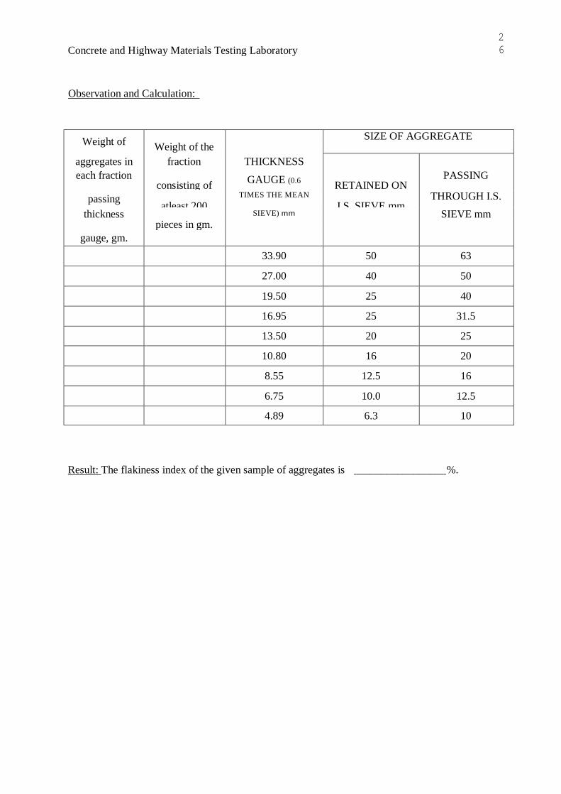
Observation and Calculation:
SIZE OF AGGREGATE Weight of Weight of the THICKNESS fraction aggregates in
PASSING GAUGE (0.6 each fraction
RETAINED ON consisting of THROUGH I.S. TIMES THE MEAN passing I.S. SIEVE mm atleast 200
SIEVE mm SIEVE) mm thickness pieces in gm. gauge, gm.
63 50 33.90
50 40 27.00
40 25 19.50
31.5 25 16.95
25 20 13.50
20 16 10.80
16 12.5 8.55
12.5 10.0 6.75
10 6.3 4.89
Result: The flakiness index of the given sample of aggregates is _________________ %.

27 Concrete and Highway Materials Testing Laboratory
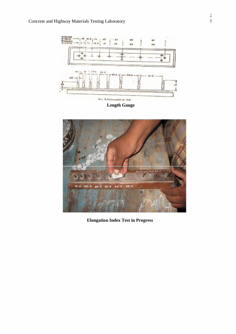
SHAPE TEST (Elongation Index)
Aim: To determine the Elongation Index of the given aggregate sample.
Apparatus: Length gauge, I.S-sieves as gIven ill the table and a balance of accuracy 0.01 Gm.
Procedure:
~ The sample is sieved through I. S-sieves specified in the table. A minimum of 200 aggregate
pieces of each fraction is taken and weighed.
~ Each fraction is thus gauged individually for length in a length gauge. The gauge length is
used should be those specified in the table for the appropriate material.
~ The pieces of aggregates from each fraction tested which could not pass through the
specified gauge length with its long side are elongated particles and they are collected
separately to find the total weight of aggregate retained on the length gauge from each
fraction.
~ The total amount of elongated material retained by the length gauge is weighed to an
accuracy of atleast 0.1 % of the weight of the test sample.
~ The weight of each fraction of aggregate passing and retained on specified sieves
sizes are found - WI, W2, W3, ............................... And the total weight of sample determined
= WI + W 2+ W 3+ ............................ = W g. Also the weights of material from each fraction
retained on the specified gauge length are found = Xl, X2, X3 ... and the total weight
retained determined = Xl +X2+X3+ ........... = X gm.
~ The elongation index is the total weight of the material retained on the various length
gauges, expressed as a percentage of the total weight of the sample gauged.
. Ind (Xl + X2 + X3 + ................................ ) 100
ongatlOn ex =-------x . (~+W; +~ + ..... )
EI
28 Concrete and Highway Materials Testing Laboratory
Length Gauge
Elongation Index Test in Progress

29 Concrete and Highway Materials Testing Laboratory
Observation and Calculation:
SIZE OF AGGREGATE Weight of Weight of the LENGTH fraction aggregates in
PASSING GAUGE (1.8 each fraction
RETAINED ON consisting of THROUGH I.S. TIMES THE MEAN retained on
I.S. SIEVE mm atleast 200 SIEVE mm SIEVE) mm
length gauge, pieces in gm. gm.
63 50 - 50 40 81.00
40 25 58.50
31.5 25 - 25 20 40.50
20 16 32.40
16 12.5 25.60
12.5 10.0 20.20
10 6.3 14.70
Result: The elongation index of a given sample of aggregate is _____________________ %.
30 Concrete and Highway Materials Testing Laboratory
SHAPE TEST (Anf!Ularitv Number)
Aim: To determine the Angularity Number of the given aggregate sample.
Apparatus:
1. The apparatus consists of a metal cylinder closed at one end and of about 3 liter capacity.
The diameter and height of this being approximately equal i.e., about 15.64cms diameter and
15.64cms height.
2. A metal tamping rod of circular cross section 1.6cms in diameter and 60cms in length rounded
at one end.
3. I.S. sieves of sizes 20, 16, 5, 10, 6.3 and 4.75mm and balance of capacity IOkg to weigh upto
O.lgm.
Procedure:
~ Metal cylinder is calibrated by determining the weight of water at 27°C required to fill it, so that
no meniscers is present above the rim of the container.
~ The sample of single size aggregate retained between the specified pair of sieves is dried in an
oven at a temperature 100°C to 110°C for 24 hours and cooled prior to testing.
~ The aggregates are placed in the cylinder and subjected to 100 blows of the tamping rod at a rate
of about 2 blows per second. Each blow is applied by holding the rod vertically with its
rounded end 5cms above the surface of the aggregates and releasing it so that it falls vertically
and no force is applied to the rod.
~ The process of filling and tamping is repeated exactly as described above with a second and third
layer of aggregate.
~ After the third layer is tamped, the cylinder is filled to over flowing and the aggregates are struck
off level with the top using a tamping rod as a straight edge.
~ The aggregate with cylinder is then weighed accurately.
~ All the above steps are repeated on another sample and averages of two are represented.

31 Concrete and Highway Materials Testing Laboratory
~ The angularity number is calculated from the formula,
. lOOW AngularIty Number = 67 - -- where, CG
W = Mean weight of aggregates in the cylinder, gm. C =
Weight of water required in the cylinder, gm.
G = Specific gravity of aggregate.
Observation and Calculation:
Details of Sample Trailt Trail 2 Average
Weight of aggregate filling the cylinder to the
nearest five grams
Result: The angularity number of given aggregate sample = ___________________ _
Viva Voce: 1. Explain what is meant by flaky and elongated particles?
2. Explain Angularity Number. How is it found?
3. What do you understand by the term Combined Index?

32Concrete and Highway Materials Testing Laboratory
Reference:
1. Indian Standard Methods of Test for Aggregate for concrete IS: 2386 Part-I, Indian Standards
Institution.
2. Indian Standard Specifications for Coarse and Fine Aggregate from Natural Sources for
Concrete, IS: 383 Indian Standards Institution.
3. S.K. Khanna, C.E.G. Justo, Highway Material Testing Laboratory Manual, Nem Chand &
Bros., Roorkee.

Building Materials Laboratory Manual Fall 2007-2008
Prepared by: B. J. Farid 16
Test No.5
“Unit Weight and Voids in Aggregate in its compacted
or loose condition”
(ASTM C 29 – 89)
Scope: This test method covers the determination of unit weight in a compacted or
loose condition and calculation of voids in fine and coarse aggregates. This test
method is applicable to aggregates not exceeding (100mm) in N.M.S.
Materials:
Sample of, preferably, oven dry fine aggregate and an other of oven-dry coarse
aggregate.
Apparatus:- 1. A balance accurate to 0.5gm.
2. Measure: A cylindrical metal measure preferably provided with handles. Its
capacity shall conform to the limits below:
N.M.S (mm) Capacity of measure (m3)
12.5 0.0028
25 0.0093
37.5 0.014
100 0.028
Note: - The indicated size measure may be used to test aggregate of
N.M.S equal to or smaller than that listed.
3. Tamping Rod (A round, straight steel rod (l6mm) in diameter and
approximately 600mm in length with a rounded to a hemispherical tip.
4. Containers and shovel or scoop.

Building Materials Laboratory Manual Fall 2007-2008
Prepared by: B. J. Farid 17
Procedure:
A- Calibration of the measure:
1- Fill the measure with water at room temperature and cover with a piece of plate
glass in such away as to eliminate bubbles and excess water.
2- Determine the weight of the water in the measure.
3-Measure the temperature of water and determine its density from table below:-
Density of water
Temperature (0C) Density (kg/m
3)
15.6 999.01
18.3 998.54
21.1 997.97
23 997.54
23.9 997.32
26.7 996.59
29.4 995.83
Note: Use interpolating if necessary.
4- Calculate the volume, V of the measure by dividing the weight of water required
to fill the measure by its density.
B- Procedure of the test:-
1. Weigh the cylinder (empty).
2. Fill the cylinder to overflowing by means of a shovel or scoop, discharging the
aggregate from a height not to exceed 50mm above the top the cylinder edge.
Exercise care to prevent, so far as possible, segregation of the particle sizes of
which the sample in composed. Level the surface of the aggregate with the
fingers or straight edge in such way that any slight projections of the larger
pieces of the coarse aggregate approximately balance the larger voids in the
surface below the top of the cylinder
3. Determine the weight of the measure plus its contents, and calculate the
weight of the aggregate by subtracting the empty weight of the cylinder.

Building Materials Laboratory Manual Fall 2007-2008
Prepared by: B. J. Farid 18
4. Empty the cylinder and refill it again to one third of its height and rod the
layer of aggregate with (25) strokes of the tamping rod evenly distributed over
the surface. Fill the cylinder two-thirds full and again level and rod as
previous. Finally, of the cylinder to overflowing and rod again in the manner
previously mentioned. Level the surface of the aggregate with the fingers or a
straight edge in such away as that mentioned in (step 3).
5. In Roding the first layer, do not allow the rod to strike the bottom of the
measure forcibly. In Roding the second layer and third layer, use only enough
force to cause the tamping rod to penetrate the previous layer of aggregate.
6. Determine the weight of the measure plus its contents and calculate the wt. Of
aggregate.
7. Repeat the same procedure for the fine aggregate sample.
Calculations:
1-Unit weight: calculate the unit weight for the rodding or shoveling procedure
follows:- M = ( G-T )/ V
Where :-
M= unit weight of the aggregate (kg/m3)
G= Weight of the aggregate plus the cylinder (kg)
T= Weight of the empty cylinder (kg)
V= Volume of the cylinder (m3)
Note: The unit weight determined by this test method is for aggregate in an oven- dry
condition.
2-Void content:- Calculate the void content in the aggregate using the unit weight
determined by either the rodding or shoveling procedure as follows:
%void= (S )(W) – (M) x100
( S) (W)
Where S= bulk specific gravity (from tests 2+3)
W= density of water (1000kg/m3 )

Building Materials Laboratory Manual Fall 2007-2008
Prepared by: B. J. Farid 19
3-Put your results in a table like that shown below.
Fine Aggregate Coarse Aggregate
Compacted Loose Compacted Loose
Unit weight
kg/m3
Voids%
Note:
Normal-Weight aggregate density: (1280-1920) kg/m3
Fig.(8) The cylindrical metal measures for the fine and coarse aggregates
Building Materials Laboratory Manual Fall 2007-2008
Prepared by: B. J. Farid 20
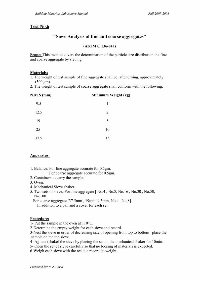
Test No.6
“Sieve Analysis of fine and coarse aggregates”
(ASTM C 136-84a)
Scope: This method covers the determination of the particle size distribution the fine
and coarse aggregate by sieving.
Materials: 1. The weight of test sample of fine aggregate shall be, after drying, approximately
(500 gm).
2. The weight of test sample of coarse aggregate shall conform with the following:
N.M.S (mm) Minimum Weight (kg)
9.5 1
12.5 2
19 5
25 10
37.5 15
Apparatus:
1. Balance: For fine aggregate accurate for 0.5gm.
For coarse aggregate accurate for 0.5gm.
2. Containers to carry the sample.
3. Oven.
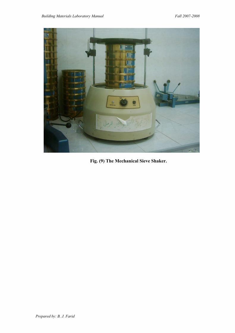
4. Mechanical Sieve shaker.
5. Two sets of sieve:-For fine aggregate [ No.4 , No.8, No.16 , No.30 , No.50,
No.100]
For coarse aggregate [37.5mm , 19mm ,9.5mm, No.4 , No.8]
In addition to a pan and a cover for each set.
Procedure:
1- Put the sample in the oven at 110°C.
2-Determine the empty weight for each sieve and record.
3-Nest the sieve in order of decreasing size of opening from top to bottom place the
sample on the top sieve.
4- Agitate (shake) the sieve by placing the set on the mechanical shaker for 10min.
5- Open the set of sieve carefully so that no loosing of materials is expected.
6-Weigh each sieve with the residue record its weight.

Building Materials Laboratory Manual Fall 2007-2008
Prepared by: B. J. Farid 21
7- Tabulate your data in a suitable shape.
8. Make sure that the summation of the residue weights equals to the original
sample weight with a difference not more than 1% of the original weight.
9-The table should contain:-
No. of
sieve
Sieve
empty Wt
Sieve
+residue Wt
Residue
Wt
Residue
%
% Cum
Residue
%
Passing
10-Fineness Modulus for fine aggregate can be determined as: -
F.M. = Σ cumulative residue percentage
100
It must be within-(2.6 - 3.1) for sand.
Notes:
1-The sieves dimensions are:
1.5'' 1'' 3/4'' 1/2'' 3/8'' 4 8 16 30 50 100 No. of sieve
37.5 25.4 19 12.5 9.5 4.75 2.36 1.18 0.6 0.3 0.150
Size of
opening
(mm)
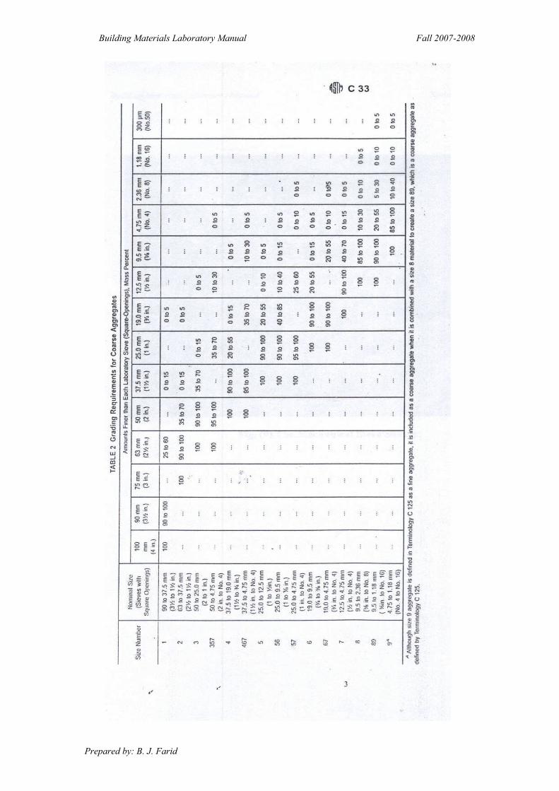
2- The results must be companied with ASTM Specification [C33-99a]
a- For Fine aggregate:
% Passing Sieve size Sieve No.
100 1.9mm 3/4''
95-100 4.75mm No.4
80-100 2.36mm No.8
50-85 1.18mm No.16
25-60 0.600mm No.30
10-30 0.3mm No.50
2-10 0.15mm No.100
b- For Coarse aggregate: See table (2).
Building Materials Laboratory Manual Fall 2007-2008
Prepared by: B. J. Farid 22
Building Materials Laboratory Manual Fall 2007-2008
Prepared by: B. J. Farid 23
Fig. (9) The Mechanical Sieve Shaker.

Building Materials Laboratory Manual Fall 2007-2008
Prepared by: B. J. Farid 24
Test No.7
“Materials Finer than 75µm (No. 200) Sieve in Mineral
Aggregate by Washing ”
(ASTM C117-87)
Scope: This test method covers determination of the amount of materials finer than a
75µm (N0.200) sieve in aggregate by washing. Clay particles and other aggregate
particles that are dispersed by the wash water, as well as water –soluble materials, will
be removed from the aggregate during the test.
Materials :
the mass of the test sample, after drying , shall conform with the following:
Minimum Mass (gm) Nominal Max. Size
300 4.5mm or smaller
1000 9.5mm
2500 19mm
5000 37.5mm or larger
Apparatus :
1- Balance accurate to 0.1g or 0.1% of the test mass , whichever greater.
2- Sieves: 75µm (No.200) sieve + 1.18mm (No.16) sieve .
3- Container.
4- Oven.
Procedure:
o
5C
+o
Dry the test sample to constant mass at a temperature of 110 C -1
Determine the mass to the nearest 0.1gm of the test sample.
2- Place the test sample in the container and add sufficient water to cover it. Agitate
the sample to result in complete separation of all particles finer than the 75µm
(No.200) sieve from the coarser particles, and to bring the fine materials into
suspension. immediately pour the wash water containing the suspended and
dissolved solids over the nested sieves, arranged with the coarser sieve on top .
3- Add a second charge of water to the sample in the container, agitate , and decant as
before. Repeat this operation until the wash water is clear.

Building Materials Laboratory Manual Fall 2007-2008
Prepared by: B. J. Farid 25
4- Return all materials retained on the nested sieve by flushing to the washed sample .
Dry the washed sample to constant mass at a temp. of 110 + 5 Co and determine
the mass to the nearest 0.1% of the original mass of the sample .
5- Calculate the amount of materials passing 75µm (No.200) sieve by washing as
follows:
100 B
C-B A =
Where :
A = percentage of material finer than 75µm sieve by washing .
B = Original dry mass of sample .(gm)
C = Dry mass of sample after washing.(gm)
Note:
According to [C33-99a] ASTM.
[A] must be not more than (3%), in fine aggregate for concrete.

Cement Testing

BLAINE'S AIR PERMEABILITY TEST Theorv and Scope:
The degree of fineness of cement is a measure of the mean size of the grains in the cement. The
rate of hydration and hydrolysis and consequent development of strength depends upon the fmeness of
cement. To have the same rate of hardening in different brands of cement, the fineness has been
standardized. The finer cement has quicker action with water and gains early strength though it's
ultimate strength remains unaffected. However the shrinkage and cracking of cement will increase
with fineness of cement.
Aim: To determine the specific surface of cement Pozzo1onas.
Apparatus: The Blaine's variable flow air permeability apparatus.
Procedure:
Calibration of the Blaine apparatus.
~ Calculate the volume of the compacted bed of cement V by the following formula V=
(W A- WB)/P
Where W A= mass of the mercury required to fill the permeability cell
WB=mass of the mercury to fill the portion of the cell not
occupied by the bed of cement formed by 2.8 gm of standard cement
sample.
P = Density of mercury at the temperature of test.
The masses W A and W B are obtained by weighing the mercury in the crucible.
~ Determine the mass of sample W required to produce a bed having porosity of 0.500 (= e) as
follows
W= 3.15V*(1 - e)
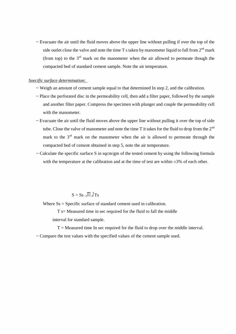
~ Evacuate the air until the fluid moves above the upper line without pulling if over the top of the
side outlet close the valve and note the time T s taken by manometer liquid to fall from 2nd mark
(from top) to the 3rd mark on the manometer when the air allowed to permeate though the
compacted bed of standard cement sample. Note the air temperature.
Soecific surface determination:
~ Weigh an amount of cement sample equal to that determined In step 2, and the calibration.
~ Place the perforated disc in the permeability cell, then add a filter paper, followed by the sample
and another filter paper. Compress the specimen with plunger and couple the permeability cell
with the manometer.
~ Evacuate the air until the fluid moves above the upper line without pulling it over the top of side
tube. Close the valve of manometer and note the time T it takes for the fluid to drop from the 2nd
mark to the 3rd mark on the manometer when the air is allowed to permeate through the
compacted bed of cement obtained in step 5, note the air temperature.
~ Calculate the specific surface S in sqcm/gm of the tested cement by using the following formula
with the temperature at the calibration and at the time of test are within ±3% of each other.
S = Ss ..JT/..J Ts
Where Ss = Specific surface of standard cement used in calibration.
T s= Measured time in sec required for the fluid to fall the middle
interval for standard sample.
T = Measured time In sec required for the fluid to drop over the middle interval.
~ Compare the test values with the specified values of the cement sample used.

a)
FHt~r PQDer
dlsc~ Coutlfj ng t{J t.it i . i.
1cp Of flUJI1 0 mm-~ ~~~ 1eIWI
Perfo,rdttd metal disc with :30 t(J 40 f1o{es t mm ~ EQ 1Jt] lly distnbuHd
CEL!. MANOMl!:TER
Blaine Air Permeability Apparatus
010155· t t.fbe 9111m O.D.
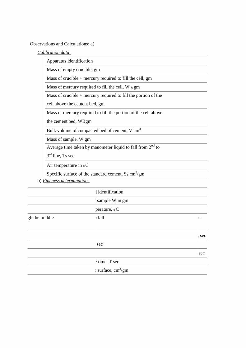
Observations and Calculations: a)
Calibration data
Apparatus identification
Mass of empty crucible, gm
Mass of crucible + mercury required to fIll the cell, gm
Mass of mercury required to fill the cell, W A gm
Mass of crucible + mercury required to fill the portion of the
cell above the cement bed, gm
Mass of mercury required to fill the portion of the cell above
the cement bed, WBgm
Bulk volume of compacted bed of cement, V cm3
Mass of sample, W gm
Average time taken by manometer liquid to fall from 2nd to
3rd line, Ts sec
Air temperature in 0 C
Specific surface of the standard cement, Ss cm2/gm b) Fineness determination
Material identification
Mass of sample W in gm
Air temperature, 0 C
Time for liquid to fall through the middle
, sec
run, sec
run, sec
Average time, T sec
Specific surface, cm2/gm

Result: The fineness of the given cement sample = ________________ _
Viva voce:
1. What does the fineness of the cement indicate?
2. The specific surface by air permeability methods for different cements are:-
b) Ordinary cements
c)Rapid hardening cement c)
Low heat cement
3. Does it give any idea of the particle sizes present in the sample?
References: 1. Neville. A. M, Properties of concrete, 3rd edition, Pitman publishing company, 1981.
2. Gambhir. M. L, Concrete manual, 4th edition, Dhanpat Rai and Sons, Delhi.

Building Materials Laboratory Manual Fall 2007-2008
Prepared by: B. J. Farid 26
Test No.8
“Fineness of Hydraulic Cement by No.100 or No. 200 Sieve”
(ASTM C 184-83)
Scope: This test method covers determination of the finesses of hydraulic cement by
means of the 150 µm (No.100) and 75µm (No.200) sieves.
Apparatus:- 1. Sieve:- Standard 150 µm (No.100) or 75µm (No.200) sieves.
2. Balance and weights.
3. Brush: a bristle brush will be required for use in cleaning the 150 µm or 75µm
sieve.
4. A pan and a cover for the sieve.
Procedure:
1. Place 50-gm sample of the cement on the clean, dry (No.100) or (No.200) sieve
with the pan attached.
2. While holding the sieve and uncovered pan in both hands, sieve with a gentle wrist
motion until most of the fine material has passed through and the residue looks
fairly clean.13 or 4 minutes.
3. Place the cover on the sieve and remove the pan.
4.With the sieve and cover held firmly in one hand, gently tap the side of the sieve
with the handle of the brush used for cleaning the sieve.
5.Empty the pan and wipe it out with a cloth, replace the sieve in the pan and
carefully remove the cover .
6. Continue sieving without the cover for 5 to 10 min. Or until not more than
(0.05gm) of the material passes through in 1 minutes of continuous sieving.
7.Carefully open the set and transfer the residue on the sieve to a white clean paper,
and record the weight.
8. Calculate the percentage residue as:
% residue = wt. of residue x 100
50
9. Specifications requires that %retained on sieve (No.200) Shall not exceed 22%.
and on sieve (No.100) not more than 10%.
Building Materials Laboratory Manual Fall 2007-2008
Prepared by: B. J. Farid 27
Test No.9
“Normal Consistency of Hydraulic Cement”
ASTM ( C 187-86)
Scope: This test method cover the determination of the normal consistency of
hydraulic cement. That is by determining the amount of water required to prepare
cement pastes for Initial and final time of setting test.
Apparatus: 1.Weight and weighing devices.
2. Glass graduates (200 or 250) ml capacity.
3. Vicat apparatus with the plunger end, 10 mm in diameter.
4.Electrical mixer , trowel and containers.
5. Mixing glass plate 30cm x 30cm.
Procedure:
1- Place the dry paddle and the dry bowl in the mixing position in the
mixer.
2- Place all the mixing water in the bowl.
3- Add the cement to the water and allow 30 s for a absorption of the water.
4- Start the mixer at low speed for 30 s
5- Stop for (15 s) and make sure no materials have collected on the sides of the
bowel.
6- Start mixing at medium speed for (1 min).
7- Quickly form the cement paste into the approximate shape of a ball with
gloved hands
8- Putting hand at (15cm) distance, throw the cement paste ball from hand to
hand six times.
9- Press the ball into the larger end of the conical ring, completely fill the ring
with paste.
10- Remove the excess at the larger end by a single movement of the palm of the
hand. Place the ring on its larger end on the base of the plate of Vicat
apparatus.

Building Materials Laboratory Manual Fall 2007-2008
Prepared by: B. J. Farid 28
11- Slice off the excess paste at the smaller end at the top of the ring by a single
sharp- ended trowel and smooth the top. (Take care not to compress the paste).
12- Center the paste under the plunger end which shall be brought in contact with
the surface of the paste, and tighten the set-screw.
13- Set the movable indicator to the upper zero mark of the scale or take an initial
reading, and release the rod immediately. This must not exceed 30 seconds
after completion of mixing.
14- The paste shall be of normal consistency when the rod settles to a point
10±1mm below the original surface in 30 seconds after being released.
15- . Make trial paste with varying percentages of water until the normal
consistency is obtained. Make each trial with fresh cement.
16- . Prepare a table in the form:
Penetration (mm) Water Volume
(ml)
Weight of cement
(gm)
W/c
24%
26%
28%
30%
17. Draw the penetration — w/c curve.
pent.(mm)
w/c
Building Materials Laboratory Manual Fall 2007-2008
Prepared by: B. J. Farid 29
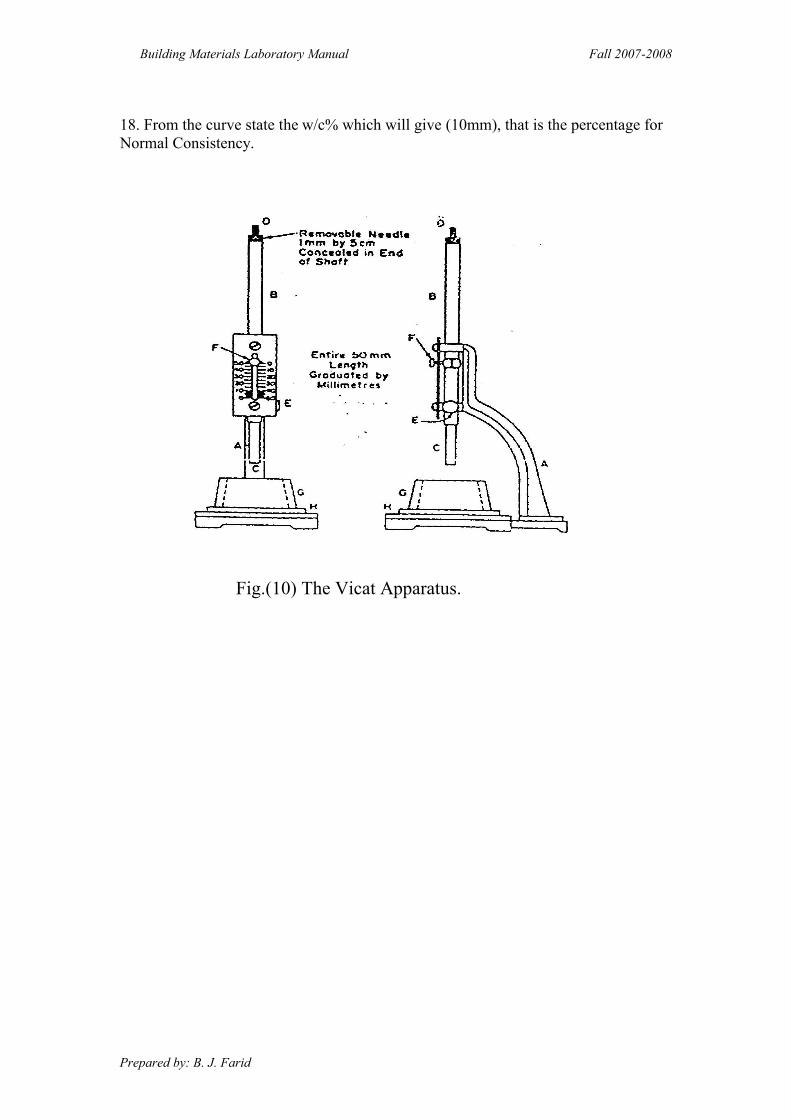
18. From the curve state the w/c% which will give (10mm), that is the percentage for
Normal Consistency.
Fig.(10) The Vicat Apparatus.

Building Materials Laboratory Manual Fall 2007-2008
Prepared by: B. J. Farid 30
Test No. 10
“Initial and Final Time of Setting of Cement”
(ASTM C191-82)
Scope: This test covers determination of the time of Setting of cement by means of
the Vicat needle.
Apparatus: 1. Vicat Apparatus with the needle end, 1mm in diameter.
2. Weights and weighing Device.
3. Glass Graduates (200 or 250) ml capacity.
4. A trowel and containers.
Procedure: 1. Weigh (400) gm cement.
2. Prepare amount of water as to that calculated in normal consistency test.
3. Prepare a cement paste following same steps mentioned in the previous test (test
No. 9). Place in Vicat conical ring like test No. 9. Don't forget to record the
time since the cement is added to the water.
4. Allow the time of setting specimen to remain in the moist cabinet for 30 minutes
after molding without being disturbed. Determine the Penetration of the 1mm
needle at this time and every (15) minutes until a penetration of 25mm or less is
obtained
5. To read the penetration, lower the needle of Vicat Apparatus until it touches the
surface of the cement paste. Tighten the screw and take an initial reading. Release
the set screw and allow the needle to settle for 30 seconds, and then take the
reading to determine the penetration.
6. Note that no penetration shall be made closer than (6mm) from any previous
penetration and no penetration shall be made closer than (9.5mm) from the inside
of the mold. Record the results of all penetration, then by drawing a curve
determine the time when a penetration of 25 mm is obtained. This is the initial
setting time
7. The final setting time is when the needle dose not sinks visible into the paste.
8. Draw a graph for (penetration — time). Show the time which gives penetration of
(25 mm) this will be the initial setting time.
Note:
According to ASTM C150:
Initial time of setting, not less than 45 min.
Final time of setting, not more than 375 min.
Building Materials Laboratory Manual Fall 2007-2008
Prepared by: B. J. Farid 31
Test No.11
“Density and Specific Gravity of cement”
(ASTM C188-87)
Scope: This test covers determination of the density of cement and its specific gravity.
The density of cement is defined as the mass of a unit volume of the solids.
Apparatus:
1- Le chatelire flask: the standard flask which is circular in cross section with special
shape and dimensions
2- Kerosene, free of water.
3- Balance.
4- Holder.
5- Water bath.
Procedure: 1- Fill the flask with Kerosene to a point on the stem between 0 and 1ml mark.
2- Put the flask in the water bath at a constant temperature for a sufficient period of
time in order to avoid flask temperature variations greater than 0.2 °C between the
initial and final readings.
3- Record the final reading on the flask.
4- Prepare (64) gm of cement weighed to the nearest (0.05) gm and place it in the
flask in small increments. Take care to avoid splashing and see that the cement
dose not adheres to the inside of the flask above the liquid.
5- After all the cement has been introduced, place the stopper in the flask and roll the
flask in an inclined position so as to free the cement from air until no further air
bubbles rise to the surface of the liquid.
6- Put the flask in the water bath as in step (2).
7- Take the final reading.
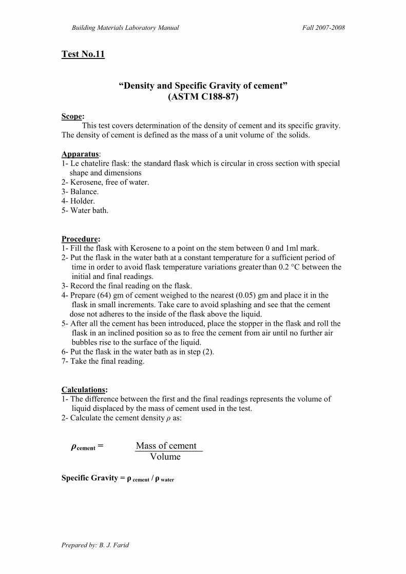
Calculations: 1- The difference between the first and the final readings represents the volume of
liquid displaced by the mass of cement used in the test.
2- Calculate the cement density ρ as:
Mass of cement cement = ρ
Volume
Specific Gravity = ρ cement / ρ water

Building Materials Laboratory Manual Fall 2007-2008
Prepared by: B. J. Farid 32
Fig.(11) Le Chatelire flask.

Concrete Technology Laboratory Manual Spring 2007-2008
Prepared by: B.J. Farid 2
Test No. 1
“Compressive Strength of Hydraulic Cement Mortars''
''Using 50 mm Cube Specimens”
( ASTM C109-88 )
eScop This test method covers determination of the compressive strength of cement mortars, using 2 in ( 50 mm ) cube specimens.
Apparatus 1- Weights and weighing device. 2- Glass Graduate . 3- Specimens molds: three cubes of (50mm) side. 4- Mixer ( electrically driven mechanical mixer of the type equipped with paddle and mixing bowl). 5- Testing machine. 6- Tamper and trowel.
Materials:
Graded standard sand should be used (C778) . with cement in the proportion 1 Cement : 2.75 Sand by weight. Use water – cement ratio of 0.485 for all Portland cements and 0.460 for all air- entraining Portland cements.
Note: For other than Portland and air- entraining Portland cements, do flow table test , to determine the amount of mixing water.
Procedure:
A. Preparation of Mortar :-
1. Weigh (300)gm of cement and Prepare the corresponding weights of standard sand and water.
2. Place the dry paddle and the dry bowl in the mixing position in the mixer . Then introduce the materials for a batch into the bowl and mix in the following manner: i- Place all the mixing water in the bowl. ii-Add the cement to the water, then start the mixer and mix at the low speed (140± 5 r/ min) for (30 s).
iii-Add the entire quantity of sand slowly over a (30 s) period , while mixing at slow speed.

Concrete Technology Laboratory Manual Spring 2007-2008
Prepared by: B.J. Farid 3
.s30 and mix for ) min/r10 + 285 (change to medium speed, Stop the mixer-vi v-Stop the mixer and let the mortar stand for 1.5 min . During the first (15 s) of this interval, quickly scrape down into the batch any mortar that may have collected on the side of the bowl. vi-Finish by mixing for (1min) at medium speed.
B-Molding test specimens: i-Thinly cover the interior faces of the specimen molds with oil. ii-Start molding the specimens within a total time of not more than 2.5 min after completion of mixing . iii-Place a layer of mortar a bout 25 mm (half the depth of the mold ) in all the cube specimens . iv- Tamp the mortar in each cube 32 times (4x8) , about 4 rounds , each round to be at right angles to the other.
The tamping pressure shall be just sufficient to insure uniform filling of the molds. v- The 4 rounds of taming shall be completed in one cube before going to the next . vi-When the tamping of the first layer in all cubes is completed , fill the molds with
the remaining mortar and tamp as specified for the first layer . vii- Cut off the mortar to a plane surface with a straight edge. viii- Keep the molds in a moist room for 20-24 hours then open them and keep the specimens in a water basin for a week.
C-Testing specimens:
em with adry th, out of the basin the specimenstake, ) hours 3 +(days 7 After -1 clean cloth , put them, one after the other, in the testing machine. 2- The cubes must be put on one side , using extra steel plates up and down the specimen .
) in a minute 3- Start loading in a speed of 1.4 kN /sec or (350 kg /cm2
4- When failure, record load and the compressive strength.
:Calculations 1-Table the results:
Compressive strength( MPa) Load(kN) Cube No.
2- Compare with [ ASTM C150-89]: σc ≥ 19.3 MPa [ For type I cement ] age 7 days
17
8
34
526
45
67
8
32
1
Concrete Technology Laboratory Manual Spring 2007-2008
Prepared by: B.J. Farid 4
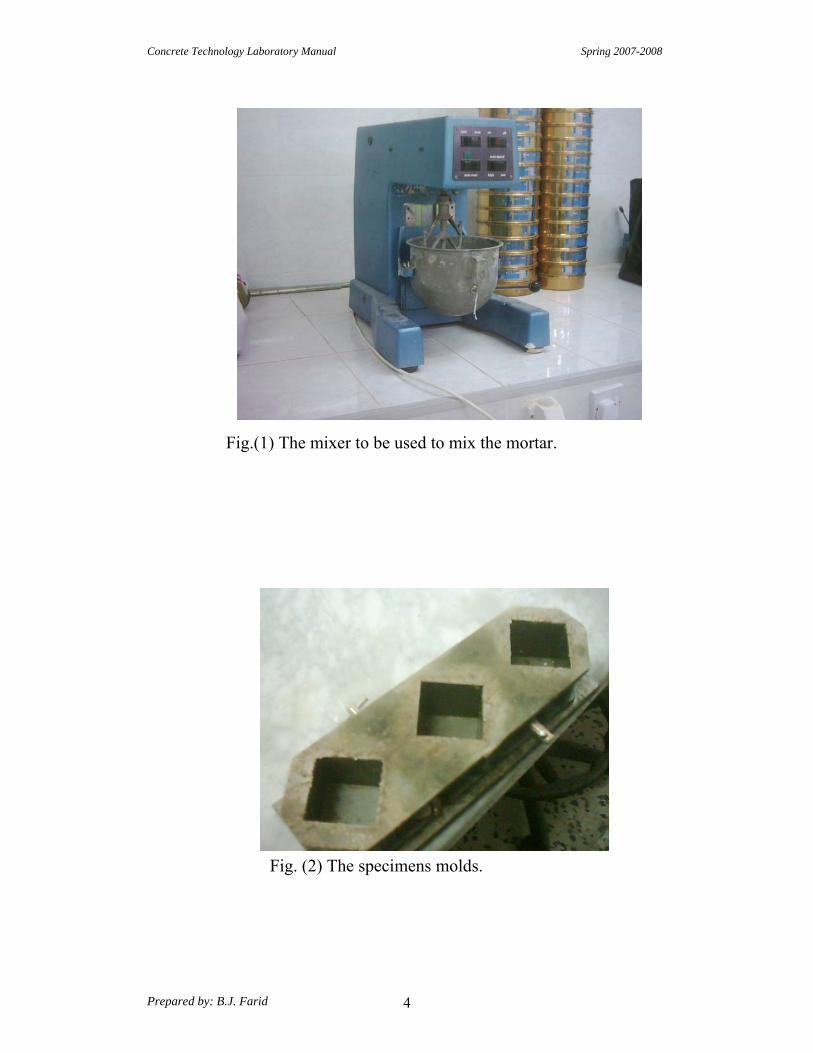
Fig.(1) The mixer to be used to mix the mortar.
Fig. (2) The specimens molds.
Concrete Technology Laboratory Manual Spring 2007-2008
Prepared by: B.J. Farid 5
2 . Test No
Tensile Strength of Cement Mortar
(ASTM C 190-85)
: Scope This test method covers the determination of the tensile strength of cement mortars employing the Briquet specimens.
: Apparatus 1- Weights and weighing device. 2- Tools and containers for mixing. 3- Briquet molds. 4- Water basin. 5- Testing Machine.
-:Procedure
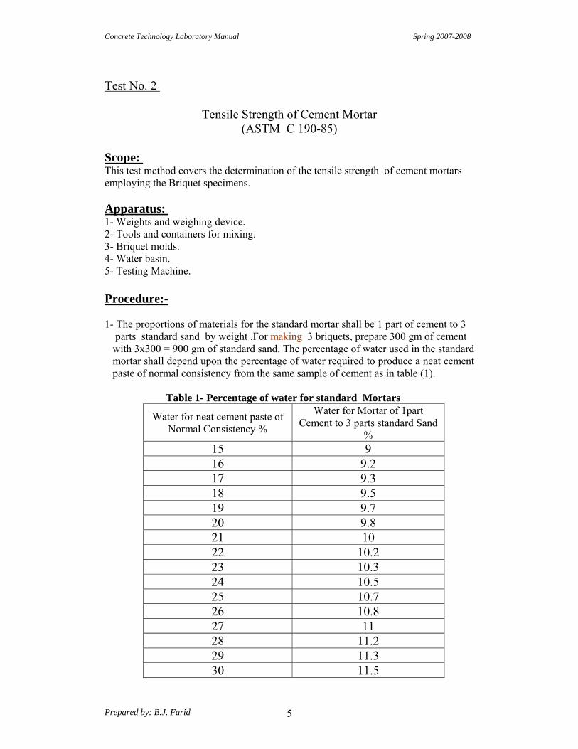
1- The proportions of materials for the standard mortar shall be 1 part of cement to 3 parts standard sand by weight .For making 3 briquets, prepare 300 gm of cement with 3x300 = 900 gm of standard sand. The percentage of water used in the standard mortar shall depend upon the percentage of water required to produce a neat cement paste of normal consistency from the same sample of cement as in table (1).
Table 1- Percentage of water for standard Mortars
Water for Mortar of 1part Cement to 3 parts standard Sand
%
Water for neat cement paste of Normal Consistency %
9 15 9.2 16 9.3 17 9.5 18 9.7 19 9.8 20 10 21
10.2 22 10.3 23 10.5 24 10.7 25 10.8 26 11 27
11.2 28 11.3 29 11.5 30

Concrete Technology Laboratory Manual Spring 2007-2008
Prepared by: B.J. Farid 6
:Note
The values being in percentage of the combined dry weights of the cement and standard sand.
2-Mix dry cement with dry sand and make a crater in the middle, then pour water in the crater, and turn the material on the outer edge into the crater within 30 seconds
by the aid of a trowel. 3- After an additional interval of 30 seconds for the absorption of the water, mix
thoroughly for 1.5 minutes. 4- Prepare Briquet molds, clean and thinly covered with a film of mineral oil. 5- Fill the molds heaping full without compacting, then press the mortar in, firmly with the thumbs, applying the force 12 times to each Briquet at points to include the entire surface. 6- Heap the mortar above the mold and smooth it off with a trowel. 7- Cover the mold with a plane glass and turn over the mold and plates. Remove the
top plate and repeat the operation of heaping, thumbing and smoothing off. 8- Keep all test specimens in moist room for 24 hours. 9-Open molds and immerse the specimens in water in the storage tank. Keep them in water for a week. 10- Take specimens out of water, dry with clean cloth then fix them in the testing machine (one after the other). 11-Record the load causing failure and the cross-sectional area at the fracture point.
-:Calculation
Load causing failure (P) Tensile strength σt = -------------------------------------------------
Area at the fracture (A)
:Note According to [ ASTM C 150-58] σt ≥ 1896 kPa [ For type 1cement → 1days in moist air +6 days in water ]
Concrete Technology Laboratory Manual Spring 2007-2008
Prepared by: B.J. Farid 7
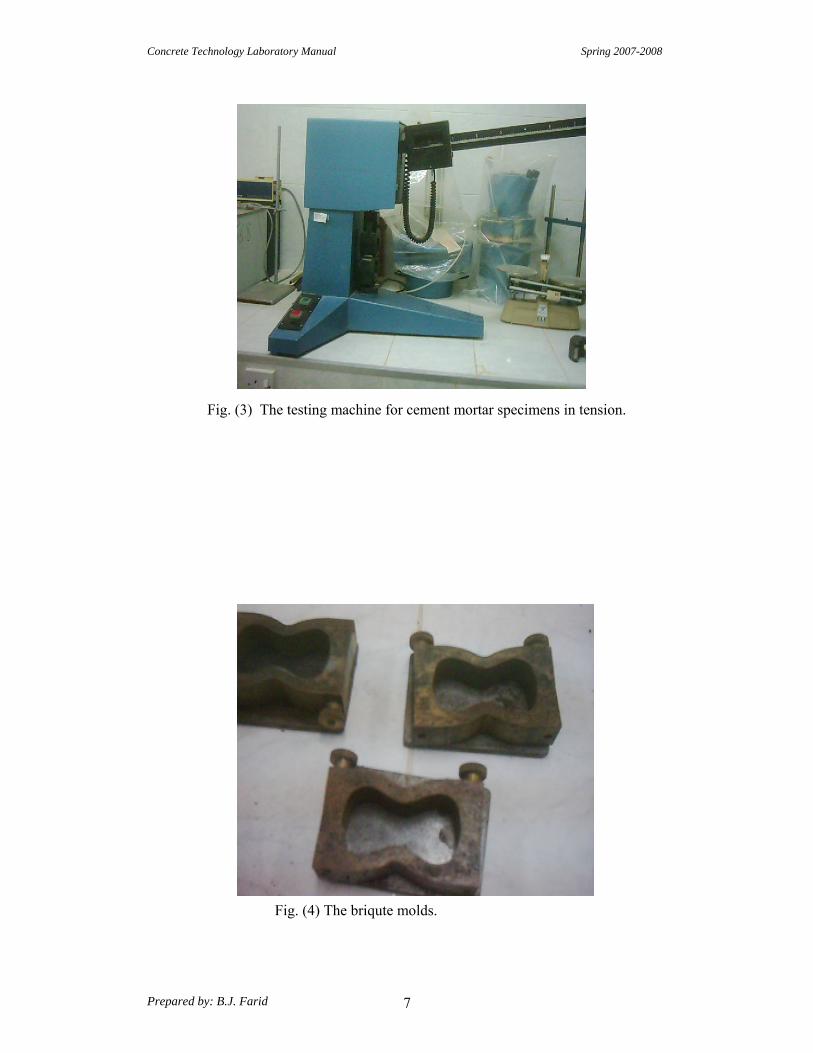
Fig. (3) The testing machine for cement mortar specimens in tension.
Fig. (4) The briqute molds.

Concrete Technology Laboratory Manual Spring 2007-2008
Prepared by: B.J. Farid 8
3. Test No
"Making and Curing Concrete Test Specimens in the Laboratory" [ASTM C192-88]
: Scope
This practice cover procedures for making and curing test specimens of concrete in the laboratory under accurate control of materials and test conditions using concrete that can be consolidated by rodding or vibration .
:Procedure for mixing Concrete
-:General 1- Mix concrete in a suitable mixer or by hand in batches of such size as to leave about 10% excess after molding the test specimens . 2- Hand- mixing procedures are not applicable to air-entrained concrete or concrete with no measurable slump.
Important not to vary the mixing sequence and procedure from batch to batch 3- It is unless the effect of such variation is under study.
:Machine Mixing
1- Put the coarse aggregate in the mixer , add some of the mixing water and the solution of admixture, when required , [add with water ]. 2- Start the mixer, then add the fine aggregate , cement and water with the mixer running .If it is impractical to add the fine aggregate, cement and water with the mixer is running , these components may be added to the stopped mixer after permitting it to turn a few revolutions following charging with coarse aggregate and some of the water. 3- Mix the concrete, after all integrates are in the mixer, for 3 minutes followed by 3 minutes rest , following by 2-minutes final mixing .
-:Hand Mixing
1-In a watertight ,clean, damp metal pan, mix the cement , insoluble admixture, if used, and the fine aggregate without addition of water until they are thoroughly blended. 2- Add the coarse aggregate and mix the entire batch without addition of water until the coarse aggregate is uniformly distributed throughout the batch . 3-Add water , and the admixture solution if used, and mix the mass until the concrete is homogenous in appearance and of the desired consistency.

Concrete Technology Laboratory Manual Spring 2007-2008
Prepared by: B.J. Farid 9
:Making Specimens
1-Place of Molding : i-Mold specimens as near as practicable to the place where they are to be stored during the first 24 hours. ii-Place molds on a rigid surface free from vibration and other disturbances iii-If it is not practicable to mold the specimens where they will be stored, move them to the place of storage immediately after being struck off. 2-Placing:- i-Place the concrete in the molds using a scoop, blunted trowel ,or shovel. Select each scoopful, trowelful, or shovelful of concrete from the mixing pan to ensure that it is representative of the batch. ii-It may be necessary to remix the concrete in the mixing pan with a shovel to prevent segregation during the molding of specimens. iii- Move the scoop or trowel a round the top edge of the mold as the concrete is discharged in order to ensure symmetrical distribution of the concrete and for minimize segregation of coarse aggregate within the mold. iv-Further distribute the concrete by use of a tamping rod prior to the start of consolidation. 3-Number of layers:- Make specimens, in layer as indicated by the test for which they are prepared or as [ASTM C 192-table1].
4-Methods of consolidation :- Preparation of satisfactory specimens requires different methods of consolidation. The methods of consolidation are:-
. rodding-i ii-internal vibration. iii-external vibration. Hints: - Rod concretes with slump greater than75mm . -Rod or vibrate concretes with slump of (25-75mm). -Consolidate by vibration concrete with slump of less than 25mm. -Do not use internal vibration for cylinders of 100mm diameter or less and beams or prisms of 100mm breadth or depth or less.
: Rodding-i
Place the concrete in the mold in the required number of layers of approximately equal volume .Rod each layer with the rounded end of the rod using the number of strokes and size of rod specified in table (2) ASTM C 192-88. Rod the bottom layer throughout its depth. Distribute the strokes uniformly over the cross-section of the mold and for each upper layer allow the rod to penetrate about 12mm into the underlying layer when the depth of the layer is less than 100mm and about (25mm) when the depth is (100mm) or more. After each layer is rodded , tap the outside of the mold lightly 10-15 times with the mallet to close any holes left by rodding.

Concrete Technology Laboratory Manual Spring 2007-2008
Prepared by: B.J. Farid 10
Vibration) ii The duration of vibration required will depend upon the workability of the concrete and the effectiveness of the vibrator. Continue vibration only long enough to achieve proper consolidation of the concrete. Fill the molds and vibrate in the required number of approximately equal layers. Place all the concrete for each layer in the mold before starting vibration of that layer. Add the final layer, so as to avoid over filling by more than (6 mm). Then finish the surface. 5- Finishing: After consolidation, strike off the surface of the concrete and float or trowel it with a wood or magnesium float. 6- Curing: 1- Covering after finishing: To prevent evaporation of water from the unhardened
concrete cover the specimens immediately after finishing, preferably with a non- absorptive, non reactive plate.
.hours 8 +24 Remove the specimens from the molds after : Removal from molds-2 3- Curing Environment: Unless otherwise specified, all specimens shall be moist
.C from the time of molding until the moment of testo.7 1+23 red at uc
Fig. (5) The mechanical mixer for concrete.
Fig.(6) The cubic mold specimen. Fig.(7) The cylindrical mold.

Concrete Testing

Concrete Technology Laboratory Manual Spring 2007-2008
Prepared by: B.J. Farid 11
:4. Test No
“The Slump of hydraulic Cement Concrete”
[ASTM C143-89a]
:Scope
This test method is used to determine the slump of freshly mixed concrete, which is an approximate measure of consistency. The test may be done in the laboratory and in field.
: Apparatus 1- Weights and weighing device. 2- Tools and containers for mixing, or concrete mixer .
3- Tamper ( 16 mm in diameter and 600 mm length) 4- Ruler 5- Slump cone which has the shape of a frustum of a cone with the following dimensions: Base diameter 20 cm Top diameter 10 cm Height 30 cm Materials thickness at least 1.6 mm
:Procedure
1- Prepare a clean, wide, flat mixing pan. ( 2-Place the dampened slump cone on one side of the pan. It shall be held firmly in
place during filling by the operator standing on the two foot pieces. 3- Place the newly mixed concrete (prepared as in test No. 3) in three layers, each approximately one third the volume of the mold. 4- In placing each scoopful of concrete, move the scoop around the top edge of the
mold as the concrete slides from it, in order to ensure symmetrical distribution of concrete within the mold.
5- Rod each layer with 25 strokes of the tamper, distribute the strokes in a uniform manner over the cross section of the mold, each stroke just penetrating into the underlying layer. 6-For the bottom layer this will necessitate inclining the rod slightly and making approximately half of the strokes spirally toward the center. Rod the bottom layer throughout its depth. 7-In filling and rodding the top layer, heap the concrete above the mold before rodding is started. 8-After rodding the top layer, strike off the surface of the concrete with a trowel,
leaving the mold exactly filled. 9- While filling and rodding, be sure that the mold is firmly fixed by feet and can’t
move. 10- Clean the surface of the base outside the cone of any excess concrete. Then immediately remove the mold from the concrete by raising it slowly in a vertical
direction.

Concrete Technology Laboratory Manual Spring 2007-2008
Prepared by: B.J. Farid 12
11-Measure the slump immediately by determining the difference between the height of the mold and the height of the vertical axis (not the maximum height) of the
specimen. 12- Clean the mold and the container thoroughly immediately after using. 13-If the pile topples [when raising the mold out of concrete ] sideways, it indicates that the materials have not been uniformly distributed in the mold and the test should be remade.
Fig.(8) Measuring the slump.
Fig. (9) Different possible slump test results.

Concrete Technology Laboratory Manual Spring 2007-2008
Prepared by: B.J. Farid 13
5. Test No
“Compacting Factor Test” BS 1881: Part 103: 1993
Four methods of determining the workability of fresh concrete are given in Part 102 to 105 of BS 1881, as follows:
Method Workability Very low Vebe time Low Vebe time, compacting factor Medium Compacting factor, Slump High Compacting factor, Slump, Flow Very high Flow
Scope This test describes the method for determining the compacting factor of concrete of low, medium and high workability. The method applies to plain and air-entrained concrete, made with lightweight, normal weight or heavy aggregates having a nominal maximum size of 40 mm or less but not to aerated concrete or no-fines concrete. The method is suitable for concretes having compacting factor in the range 0.7 to 0.98
:Apparatus
1-The compacting factor apparatus, which consists of a holder fixing two conical hoppers and a cylinder at the base. 2- Tools and containers for carrying and mixing the materials. 3- Balance.
:Procedure
1- Prepare a concrete mix following steps mentioned in test (No3).Use 8 kg of cement to cast 2 cubes and 2 cylinders. 2- Damp the two, hoppers and record the empty weight of the cylinder. 3- First, close the bases of the two hoppers. 4- Fill the upper hopper with the freshly mixed concrete (fill freely without compacting), then open the base of this upper hopper to allow concrete to fall under the effect of its weight to the lower hopper. This hopper is smaller than the upper one, thus it will be filled to overflowing. 5- Then open the base of the second hopper to allow concrete (also only under the effect of its weight ) to fall into the cylinder. Excess concrete is cut by two floats slide across the top of the mold. 6- Certain mixes have a tendency to stick in one or both of the hoppers. If this occurs, help the concrete through by pushing the tamping rod gently into the concrete from the top until the lower end emerges from the bottom of the hopper. If this does not dislodge the concrete, raise the rod and repeat the process until the concrete falls through the hopper. Count the number of times the concrete is rodded as this provides a guide to the cohesiveness of the concrete.
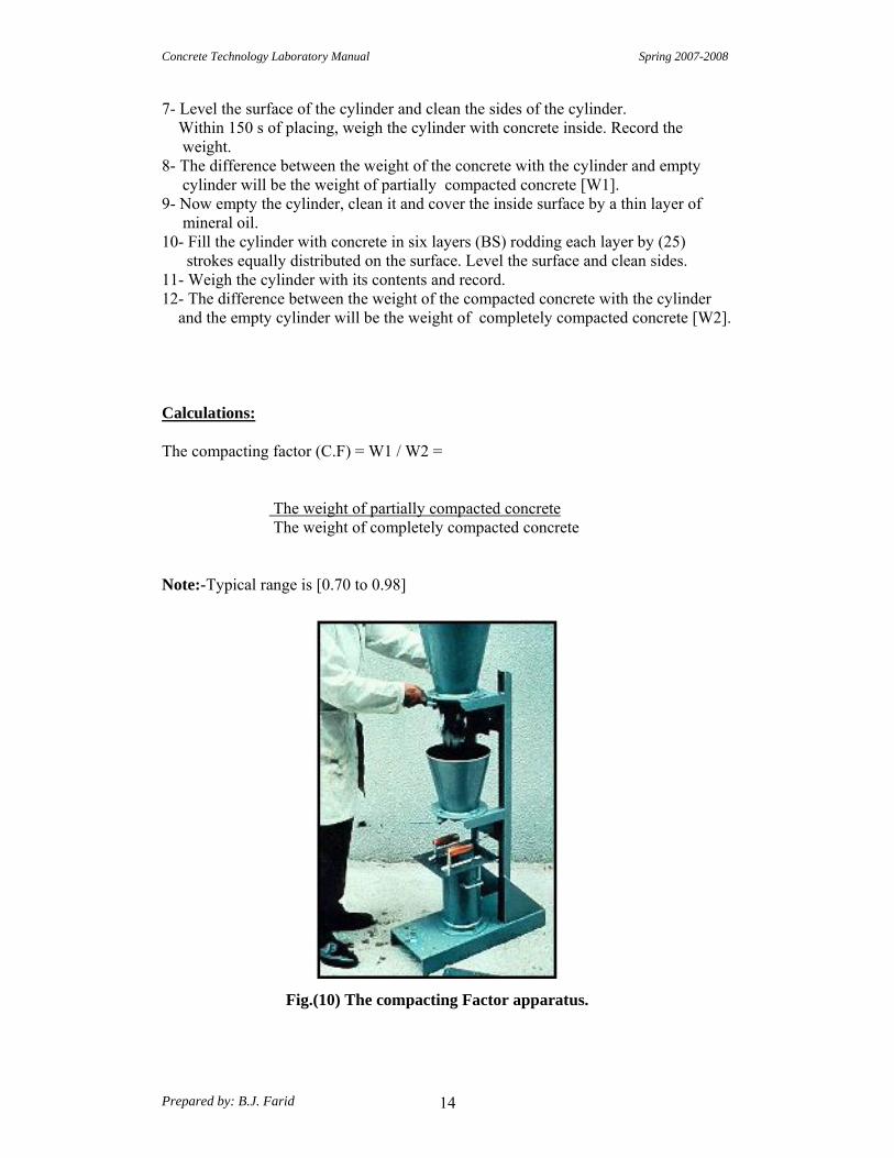
Concrete Technology Laboratory Manual Spring 2007-2008
Prepared by: B.J. Farid 14
7- Level the surface of the cylinder and clean the sides of the cylinder. Within 150 s of placing, weigh the cylinder with concrete inside. Record the
weight. 8- The difference between the weight of the concrete with the cylinder and empty cylinder will be the weight of partially compacted concrete [W1]. 9- Now empty the cylinder, clean it and cover the inside surface by a thin layer of mineral oil. 10- Fill the cylinder with concrete in six layers (BS) rodding each layer by (25) strokes equally distributed on the surface. Level the surface and clean sides. 11- Weigh the cylinder with its contents and record. 12- The difference between the weight of the compacted concrete with the cylinder
completely compacted concrete [W2]. and the empty cylinder will be the weight of
Calculations:
The compacting factor (C.F) = W1 / W2 =
The weight of partially compacted concrete The weight of completely compacted concrete
Note:-Typical range is [0.70 to 0.98]
Fig.(10) The compacting Factor apparatus.

Concrete Technology Laboratory Manual Spring 2007-2008
Prepared by: B.J. Farid 15
Test No. 6
“Flow Table Test for Fresh Concrete” BS1881: Part 105:1984
Scope: It specifies the method for determination of the flow of concrete of high to very high workability. The method applies to plain and air-entrained concrete, having a flow diameter of 500mm to 650mm when tested, made with light weight, normal weight or heavy aggregates having a nominal maximum size of 20mm or less. It does not apply to aerated concrete or no fines concrete.
Apparatus: 1- The table, which consists essentially of a board covered by a steel plate with a total mass of 16 kg .This board is hinged along one side to a base board, each board being a 700 mm square. The upper board can be lifted up to a stop so that the free edge rises 40mm .Appropriate marking indicate the location of the concrete to be deposited on the table. 2- A frustum of a cone, 200mm high with a bottom diameter of 200 mm and a top diameter of 130 mm 3- A tamping bar, made of a suitable hardwood, having a square section of side 40+1 mm and at least 200mm long. 4- Weights and weighing device. 5- Tools and containers for mixing. 6- Rule of min length 700mm.
Procedure: 1- Prepare a concrete mix as in test No.3, using mix proportions of 1:2:3 and w/c=65% 2- Moist the table top and the frustum of the cone. 3- Try lifting and dropping the table then, keep the table horizontal. 4- Hold the mold firmly in place and fill in two layers, each approximately one half the volume of the mold. Rod each layer with 10 strokes with the wooden tamper. 5- Before lifting the mould , excess concrete is removed, the surrounding table top is cleaned. 6- After an interval of 30 seconds, the mould is vertically, slowly removed within 3-6 seconds. 7- The table top is lifted slowly and allowed to drop, avoiding a significant force against the stop, 15 times, each cycle taking not less than 3.5 and not more than 5 sec. 8- In consequence, the concrete spreads and the maximum spread parallel to the two edges of the table is measured. 9- The average of these two values, given to the nearest mm, represents the flow. 10-A value of 400 mm indicates a medium workability, and 500 mm a high workability.
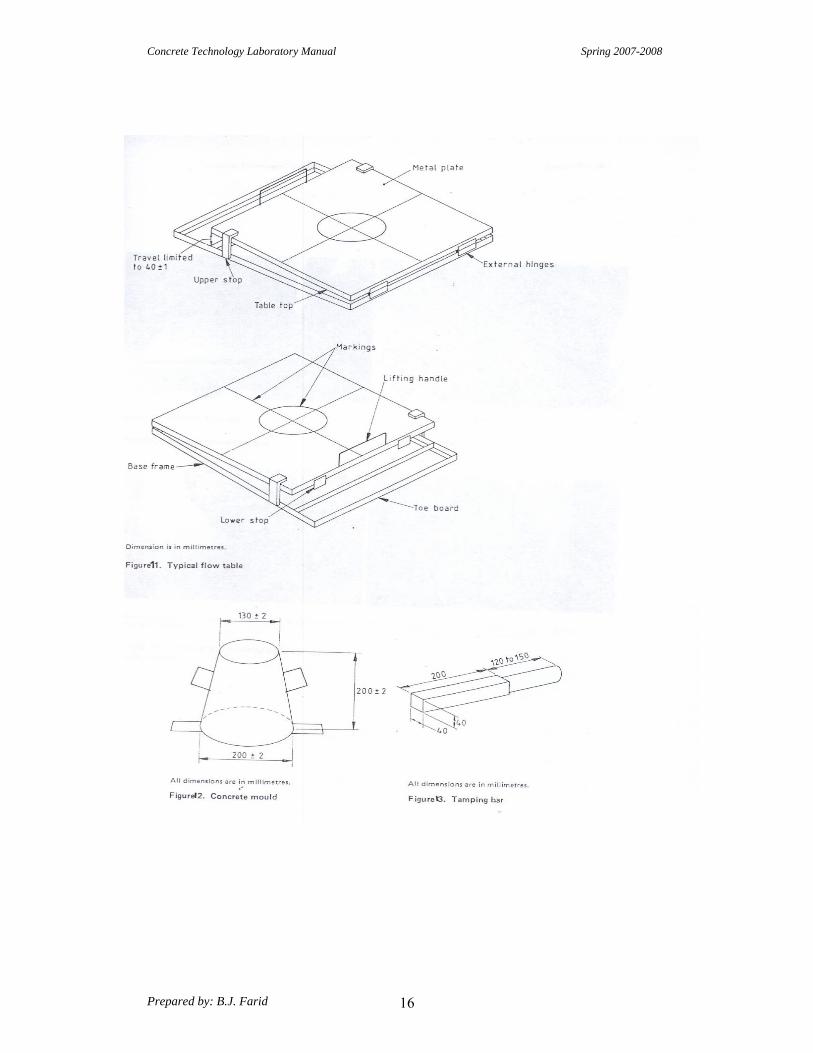
Concrete Technology Laboratory Manual Spring 2007-2008
Prepared by: B.J. Farid 16
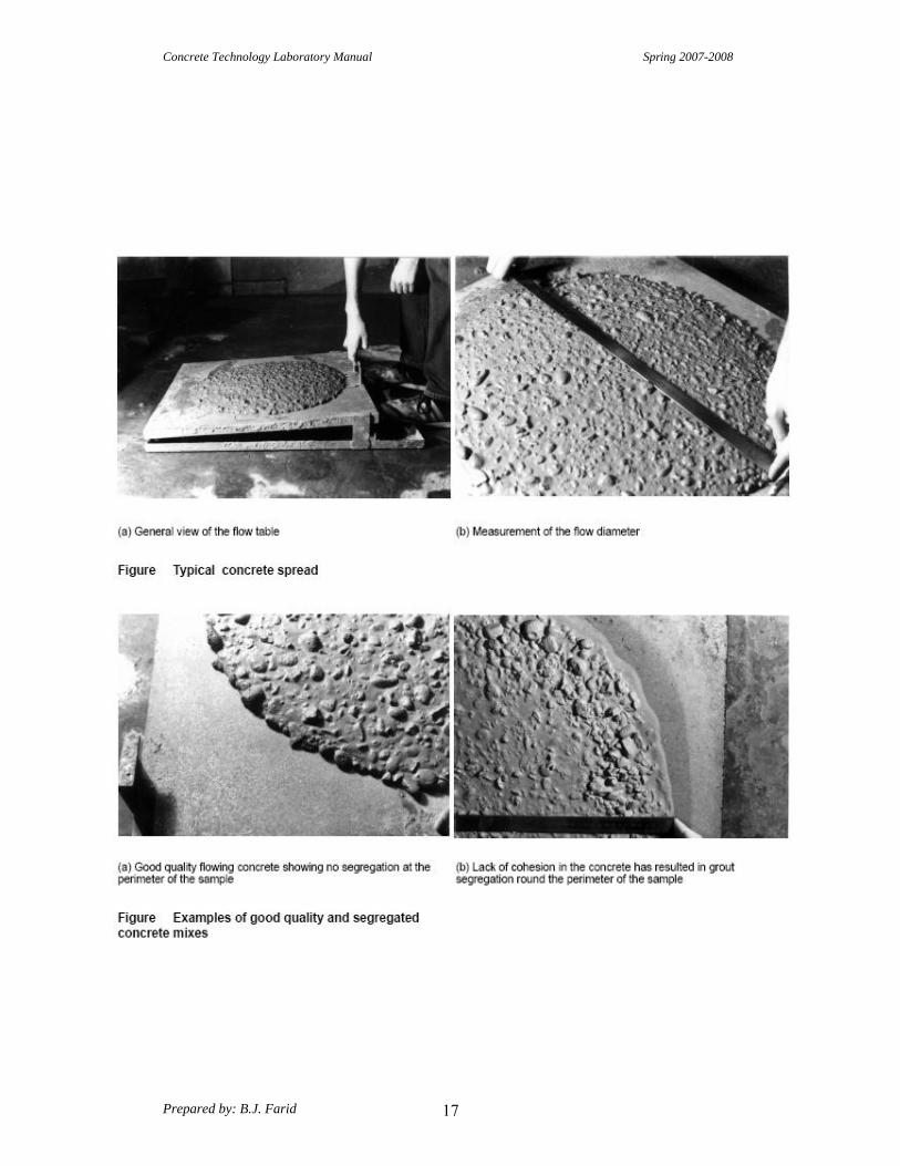
Concrete Technology Laboratory Manual Spring 2007-2008
Prepared by: B.J. Farid 17

Concrete Technology Laboratory Manual Spring 2007-2008
Prepared by: B.J. Farid 18
7. Test No
“The Compressive Strength of Cubic Concrete Specimens” BS 1881: Part 116: 1983
:Scope
The test method covers determination of compressive strength of cubic concrete specimens. It consists of applying a compressive axial load to molded cubes at a rate which is within a prescribed range until failure occurs. The compressive strength is calculated by dividing the maximum load attained during the test by the cross- sectional area of the specimen.
:Apparatus
1- Weights and weighing device. 2- Tools and containers for mixing. 3- Tamper (square in cross section) 4- Testing machine. 5- Three cubes (150 mm side)
:Procedure
1- Prepare a concrete mix as mentioned in (test No. 3 ) with the proportions suggested Such as: 1: 2: 3 with w/c = 55% by mechanical mixer. 2- Prepare three testing cubes; make sure that they are clean and greased or oiled thinly. 3-Metal molds should be sealed to their base plates to prevent loss of water. 4-Fill the cubes in three layers, tamping each layer with (35) strokes using a tamper, square in cross-section with 2.54 cm side and 38.1 cm length, weighing 1.818 kg. 5- While filling the molds, occasionally stir and scrape together the concrete remaining in the mixer to keep the materials from separating. 6- Fill the molds completely, smooth off the tops evenly, and clean up any concrete outside the cubes. 7- Mark the specimens by a slip of paper on which is written the date and the Specimen identification. Leave the specimens in the curing room for 24 hours. 8- After that open the molds and immerse the concrete cubes in a water basin for 7 days. 9- Before testing, ensure that all testing machine bearing surfaces are wiped clean. 10-Carefully center the cube on the lower platen and ensure that the load will be applied to two opposite cast faces of the cube. 11-Without shock, apply and increase the load continuously at a nominal rate within the range of ( 0.2 N/mm2.s to 0.4 N/mm2.s ) until no greater load can be sustained. On manually controlled machines, as failure is approached, the loading rate will decrease, at this stage operate the controls to maintain, as far as possible, the specified loading rate. Record the maximum load applied to each cube.
:Note
When the cubes are surface dry, or have not been cured in water, immerse them in water, for a minimum of 5 minutes, before testing. They must be tested while they are still wet.

Concrete Technology Laboratory Manual Spring 2007-2008
Prepared by: B.J. Farid 19
Type of failure Record any unusual feature in the type of failure. Refer to fig. ( ) for examples of satisfactory failure and to fig. ( ) for examples of some unsatisfactory failures.
failures are usually caused by insufficient attention to the details Unsatisfactory :Note
of making and testing specimens, such as bad molds, bad made specimens or mis-placement of cubes in the testing machine or machine fault.
Calculations Calculate the cross-sectional area of the cube face from the checked nominal dimensions. Calculate the compressive strength of each cube by dividing the maximum load by the cross-sectional area. Calculate the average for the three cubes.
Fig. (17) Unsatisfactory Failure.

Concrete Technology Laboratory Manual Spring 2007-2008
Prepared by: B.J. Farid 20
Fig.(18) The compression machine.

Concrete Technology Laboratory Manual Spring 2007-2008
Prepared by: B.J. Farid 21
8. Test No
“Compressive Strength of Cylindrical Concrete Specimens” ( ASTM C 39-86 )
:Scope
The test method covers the determination of compressive strength of cylindrical concrete specimens , such as molded cylinders and drilled cores. It is limited to concrete having a unit weight > 800 kg/m3
: Apparatus
1- Weights and weighing device. 2- Tools and containers and pans for mixing, or mixer. 3- A tamper (circular in cross-section) (16 mm in diameter and 600 mm in length). 4- Testing machine. 5- Three cylinders (150mm in diameter and 300mm in height).
: Procedure 1- Follow the same steps as in .(test No. 3) in order to prepare a fresh concrete mix. 2- The cylinder also must be clean, lightly oiled, well fixed with the base. 3- Filling the specimens will be also in three layers, roding each layer by (25) strokes using the circular section rod. 4- All other steps are the same as in test No. 6. 5-The test specimens must be tested in the moist condition with a rate of loading (0.14-0.34) MPa.
:tionCalcula
1- Calculate the compressive strength of the specimen by dividing the maximum load carried by the specimen during the test by the average cross-section area . 2- If the specimen length to diameter ratio is less than(1.8), correct the result obtained by multiplying the appropriate correction factor shown in following table :
1 1.25 1.5 1.75 L/D
0.87 0.93 0.96 0.98 Factor
:Note Factor are applicable for normal concrete strengths (from13.8-14.4) MPa.
Concrete Technology Laboratory Manual Spring 2007-2008
Prepared by: B.J. Farid 22
Test No.9
“Splitting Tensile Strength of Cylindrical Concrete Specimens”
(ASTM C496-86 ) Scope: This method covers the determination of the splitting tensile strength of cylindrical concrete specimens.
Apparatus: 1. Weights and weighing device. 2. Tools, containers and pans for carrying materials & mixing. 3. A circular cross-sectional rod (φl6mm & 600mm length). 4. Testing machine. 5. Three cylinders (φ150mm & 300mm in height). 6- A jig for aligning concrete cylinder and bearing strips.
Procedure: 1. Prepare three cylindrical concrete specimens following same steps as test No.3 2. After molding and curing the specimens for seven days in water, they can be tested. 3. Two bearings strips of nominal (1/8 in i.e 3.175mm) thick plywood, free of imperfections, approximately (25mm) wide, and of length equal to or slightly longer than that of the specimen should be provided for each specimen. 4. The bearing strips are placed between the specimen and both upper and lower bearing blocks of the testing machine or between the specimen and the supplemental bars or plates. 5. Draw diametric lines an each end of the specimen using a suitable device that will ensure that they are in the same axial plane. Center one of the plywood strips along the center of the lower bearing block. 6. Place the specimen on the plywood strip and align so that the lines marked on the ends of the specimen are vertical and centered over the plywood strip. 7. Place a second plywood strip lengthwise on the cylinder, centered on the lines marked on the ends of the cylinder. 8. Apply the load continuously and without shock, at a constant rate within , the range of 689 to 1380 kPa/min splitting tensile stress until failure of the specimen. 9. Record the maximum applied load indicated by the testing machine at failure. Note the type of failure and appearance of fracture.
Computations: Calculate the splitting tensile strength of the specimen as follows:
T = 2P πLd Where: T: splitting tensile strength, kPa P: maximum applied load indicated by testing machine, kN L: Length, m d: diameter, m
Note: This test is note a true tension test, but it fails in tension and used to indicate the tensile strength of concrete.

Concrete Technology Laboratory Manual Spring 2007-2008
Prepared by: B.J. Farid 23
Fig.(19) The jig for aligning concrete cylinder and bearing strips
Fig.(20) Fitting the cylinder in the compression machine.

Concrete Technology Laboratory Manual Spring 2007-2008
Prepared by: B.J. Farid 24
Test No. 10 “Rebound Number of Hardened Concrete”
ASTM C805-85
or
BS 1881:Part202:1986
Scope: This test is also known as the Schmidt hammer or impact hammer, and is a non-destructive method of testing concrete. The test is based on the principle that the rebound of an elastic mass depends on the hardness of the surface against which the mass impinges. Apparatus: 1- Rebound hammer. 2- Abrasive stone: consisting of medium-grain texture silicon carbide or equivalent material.
Selection of Test Surface: Concrete members to be tested shall be at least 100 mm thick and fixed within a structure. Smaller specimens must be rigidly supported. Areas exhibiting honeycombing, scaling, rough texture, or high porosity should be avoided. Concretes should be approximately the same age and moisture condition in order to be compared. Dry concretes give higher rebound numbers than wet concrete, and the surface layer of concrete may be carbonated, yielding higher rebound numbers.
Preparation of test surface: A test area shall be at least 150 mm in diameter. Heavily textured, soft, or surfaces with loose mortar shall be ground smooth with the abrasive stone. Smooth-formed or toweled surface shall be tested without grinding. Concretes over 6 months old may require grinding to a depth of 5 mm if they are to be compared to younger concretes. Grinding to this depth is not feasible without power equipment.
Procedure: 1- Firmly hold the instrument in a position that allows the plunger to strike perpendicularly to the surface tested. Gradually increase the pressure on the plunger until the hammer impacts. 2- After impact, record the rebound number to two significant figures. 3- Take ten readings from each test area. No two impact tests shall be closer together than 25 mm.
Calculation: Discard readings differing from the average of 10 readings by more than 5 units and determine the average of the remaining readings. If more than 2 readings differ from the average by 7 units, discard the entire set of readings.
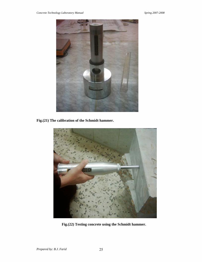
Concrete Technology Laboratory Manual Spring 2007-2008
Prepared by: B.J. Farid 25
Fig.(21) The calibration of the Schmidt hammer.
Fig.(22) Testing concrete using the Schmidt hammer.

Concrete Technology Laboratory Manual Spring 2007-2008
Prepared by: B.J. Farid 26
Test No. 11
“Pulse Velocity Through Concrete”
ASTM C598-83
or
BS:1881:Part 203:1986
Scope: 1- This test method covers the determination of the pulse velocity of propagation of compression waves in concrete. 2- The pulse velocity is independent of the dimensions of the body provided reflected waves from the boundaries do not complicate the determination of the arrival time of the directly transmitted pulse. 3- The pulse velocity V is related to the physical properties of a solid by the equation:
V2 = (K) (E)/D
Where: k =a constant E = the. modulus of elasticity, and D = the density. The relationship is independent of the frequency of the vibrations.
Apparatus: 1- The apparatus used in this test is called “ PUNDIT” . This name is derived from the initial letters of “ Portable Ultrasonic Nondestructive Digital Indicating Tester”. 2- Two transducers (54 KHz). 3- Two transducer leads. 4- Reference bar for checking zero. 5- Tin of couplant.
Procedure: 1-Before switching on the PUNDIT, the transducers should be connected to the sockets marked “TRAN” and “REC”. The connection or disconnection of the transmitting transducer should not be made while the instrument switched on. The PUNDIT may be operated from either: i) the internal battery, ii) an external battery, or iii) the A.C. mains supply. The battery operation is most convenient for field use while the mains operation is generally more suitable for laboratory use.

Concrete Technology Laboratory Manual Spring 2007-2008
Prepared by: B.J. Farid 27
2-If using the A.C. mains supply, plug the mains cable into the 3 way socket mounted on the rear panel, switch the P.S.S. to MAINS and depress the reset button to switch the PUNDIT ON. 3- Before using the PUNDIT, it should be calibrated using the reference bar. After putting the coupling agent on the transducers faces, the transducers faces are placed and pressed against the reference bar ends, using the “set free button”. The reading of the instrument should be adjusted to read the transit time recorded on the calibration bar.
4- After applying an appropriate coupling agent (such as water, oil, petroleum jelly, grease, or other viscous materials) to the transducer diaphragms, the test surface, or both, to avoid entrapped air between the contact surface of the diaphragms of the transducers and the surface of the concrete. Press the faces of the transducers against the surfaces of the concrete and measure the transit time. Measure the length of the shortest direct path between the centers of the diaphragms.
Calculation:
Calculate the pulse velocity as follows: V=L/T Where: V= pulse velocity, m/s L= distance between transducers, m T = effective transmit time, s
Fig.(23) The calibration of the PUNDIT. Fig.(24)Testing using PUNDIT

Concrete Technology Laboratory Manual Spring 2007-2008
Prepared by: B.J. Farid 28
Test No. 12
“Trial method of proportioning for concrete mixes”
Scope: This is one of the widely used methods for designing a concrete mix. The method requires that samples of the cement, fine aggregate and coarse aggregate be available and that the relation between water- cement ratio and strength be known or assumed.
Apparatus: 1- Weights and weighing device. 2- Tools and containers for mixing. 3- Slump cone and tamper.
Procedure: 1- Assuming that a concrete mix is to be designed to be used in some part of a building , say a column. 2- Assuming that the compressive strength required is 280kg /cm2, Referring to table (1) the corresponding w/c ratio is taken to be (0.534) on the assumption that the concrete is without entrained air. 3- Prepare 3 kg of cement and the corresponding amount of water. 4- Prepare 8 kg of fine aggregate and 12 kg of coarse aggregate. 5- Mix the cement prepared with the water to make a cement paste. 6- From supplies of known weight the aggregates are added in amounts dictated by judgment, with intermittent mixing, until the batch is brought to the desired consistency. 7- The batch is carefully examined in order to judge which aggregate to add. The correct amount of sand is the minimum which will produce enough mortar to fill the spaces between pieces of coarse aggregate and provide a slight excess for workability. [ Undersanding creates harshness whereas oversanding decreases yield, hence a” balanced “mix is desirable. 8- When the batch is judged to be satisfactory, the remaining supplies of aggregates are weighed and by difference the amounts used in the batch are computed. 9- Perform a slump test to check the slump. 10-The mix proportions can be calculated.

Concrete Technology Laboratory Manual Spring 2007-2008
Prepared by: B.J. Farid 29

Concrete Technology Laboratory Manual Spring 2007-2008
Prepared by: B.J. Farid 30
13 . Test No
“ Static Modulus of Elasticity of Concrete in Compression” ( ASTM C 469-87a ) or (BS 1881: Part 121: 1983)
:Scope This test method covers determination of chord modulus of elasticity ( Young’s) of molded concrete cylinders, when under longitudinal compressive stress.
:aratusApp
1-Testing Machine. 2-Compressometer for measuring the average deformation of the gage line (parallel to
the axis and centered about midheight of the specimen).
:Note The effective length of the gage line shall be not less than three times the maximum size of the aggregate in the concrete nor more than two thirds the height of the specimen; the preferred length of the gage line is one half the height of the specimen.
:Procedure
1-It is preferable to use two similar specimen, to determine the compressive strength prior to the test of modulus of elasticity.
2-Place the 2nd specimen, with the strain-measuring equipment attached on the lower platen of the testing machine. Carefully align the axis of the specimen with the center of the machine. 3-Load the specimen at least twice. Do not record any data during the first loading, but observe the performance of the gages and correct any usual behavior prior to the second loading.
s /kPa ) 34 +241 ( at a constant rate , Apply the load continuously and without shock-4 or (3.66-4.86 ) kN/s. 5-Record, without interruption of loading, the applied load and longitudinal strain. The first reading is when the stress equals ( 0.5 MPa) or the load ( 8.8 kN) [ according to BS ], or when the strain is 50 x 10-6 [ according to ASTM]. The 2nd record is when σ = f’
c /3 [ BS] , or σ = 0.4 f’c [ASTM].
6- Remove compressometer and continue loading to failure. Calculations
1- Calculate the modulus of elasticity as follows:
E = Δσ / ∆Є = ( σ2 - σ1 ) / ( Є2 - Є1 ) Where: E = Secant (chord) modulus of elasticity.

Concrete Technology Laboratory Manual Spring 2007-2008
Prepared by: B.J. Farid 31
Fig. (26) Fixing the Compressometer for measuring the average deformation of the concrete cylinder.

6
EGM3520L Material Testing Lab Concrete Mix Design
Concrete Mix Design (Method of Goldbeck and Gray, or b/bo method) The method of Goldbeck and Gray has also been called b/bo method and is sometimes referred to ACI method. This method is based on the absolute volumes of the material in a unit volume of concrete. The method takes into account a b/bo ratio. The term b equals the volume of coarse aggregate in a unit volume of concrete. The bo term equals the solid volume of coarse aggregate in a unit volume of Dry-rodded coarse aggregate. The term b/bo equals the dry-rodded volume (Bulk volume) of coarse aggregate in a unit of concrete. The procedure of design of concrete mixtures involves the use of data from tables 1 to 3 which have been prepared by Goldbeck and Gray. These tables are utilizes for typical materials. The steps in performing a concrete mix design will be listed and then an example will be given.
b = the solid volume of coarse aggregate in a unit volume concrete. b0 = the solid volume of coarse aggregate in a unit volume of dry-rodded coarse
aggregate. b/b0 = the dry-rodded volume of coarse aggregate in a unit volume of concrete.
1. Concrete Materials: contains Cement, Water, Coarse Aggregate, and Fine
Aggregate. 2. Concrete Mix Design Procedure:
(1) Determine the bulk dry specific gravities of fine and coarse aggregates.
(2) Determine the dry-rodded unit weight of the coarse aggregate.
(3) Determine the fineness modulus of the fine aggregates and the absorption of fine and coarse aggregates.
(4) Compute the solid unit weights of cement, fine aggregate, and coarse aggregate.
(5) Calculate the bo of coarse aggregate as follows:
3
3
//
ftweightsolidftweightroddeddrybo
−=
(6) According to the size of coarse aggregate and the fineness modulus of the fine aggregate, find the b/bo value from Table 1. ∴ b = (b/bo) bo = the solid volume of coarse aggregate in a unit volume of
concrete

7
(7) According to the size of coarse aggregate, 28-day compressive strength desired, and slump, find the required water, cement, and air from Table 2 (non-air entrained concrete) or Table 3 (air-entrained concrete).
(8) Determine the solid volumes of cement, water, coarse aggregate, and air and get the total volume of them.
(9) Determine the solid volume of fine aggregate in a cubic yard of concrete as follows: [ 1 yd3 (27 ft3) – sum of item (8)]
(10) Convert the solid volumes to lbs/yd3 of concrete.
(11) According to the absorption of fine and coarse aggregates, calculate the additional water requirement.
3. Example: Data
1. Coarse Aggregate:
a. Size: No. 4 (3/16 in.) to ½ in., angular aggregate
b. Absorption = 0.4%
c. Bulk dry specific gravity = 2.7
d. Dry-rodded unit weight = 101.5 lb/ft3
2. Fine Aggregate: a. Fineness modulus = 2.7
b. Absorption = 0.8%
c. Bulk dry specific gravity = 2.5
3. Concrete: a. 3 in. slump
b. 3000 psi 28-days compressive strength for non-air-entrained concrete
Concrete Mix Design
1. Coarse Aggregate:
Solid unit weight = S.G. × Unit weight of water = (2.7) (62.4) = 168.48 (lb/ft3)
602.048.1685.101
//
3
3
==−
=ftweightsolid
ftweightroddeddrybo
From Table 1, b/bo = 0.56

8
∴b = (b/bo) . bo = (0.56)(0.602) = 0.337 yd3
= the solid volume of coarse aggregate in a unit volume of concrete
From Table 2, for No. 4 to ½ in. angular coarse aggregate, 3 in. slump, and 3000 psi 28-days compressive strength, water requirement = 42 gal/yd3 of concrete
Cement requirement = 5.4 sacks/yd3 of concrete
Entrapped air = 2.5%
2. Cement:
Specific gravity = 3.14 Solid unit weight = (3.14)(62.4) = 195.94 lb/ft3 1 sack = 94 lb ⇒ Cement = (94/195.94) = 0.48 ft3 (solid volume)
3. Water:
1 ft3 = 7.5 gallon 4. Fine Aggregate:
Specific gravity, S.G. = 2.5 Solid unit weight = (2.5)(62.4) = 156 lb/ft3
5. Required solid volumes for each material in 1 yd 3 concrete:
a. Coarse aggregate: 0.337 yd3 = (0.337 × 27) ft3 = 9.10 ft3 b. Cement: 5.4 (sacks) × 0.48 = 2.592 ft3 c. Water: 42 gal = (42/7.5) ft3 = 5.6 ft3 d. Air: 2.5% × 27 ft3 = 0.675 ft3
Total solid volume = 9.10 + 2.592 + 5.6 + 0.675 = 17.967 ft3
e. Fine aggregate: 27 ft3 – 17.967 ft3 = 9.033 ft3
6. Convert the solid volume to weight in 1 yd 3 concrete:
a. Coarse aggregate: 9.10 × 168.48 (solid unit weight) = 1533.17 lb b. Cement: 2.592 × 195.94 = 507.88 lb c. Fine aggregate: 9.033 × 156 = 1409.15 lb d. Water: 5.6 × 62.4 = 349.44 lb Water absorbed by coarse aggregate = 0.4% × 1533.17 = 6.13 lb Water absorbed by fine aggregate = 0.8% × 1409.15 = 11.27 lb Total water: 349.44 + 6.13 + 11.27 = 366.84 lb Total weight in 1 yd3 concrete = 1533.17 + 507.88 + 1409.15 + 366.84 = 3817.04
lb ⇒ 3817.04/27 = 141.4 lb/ft3 of concrete
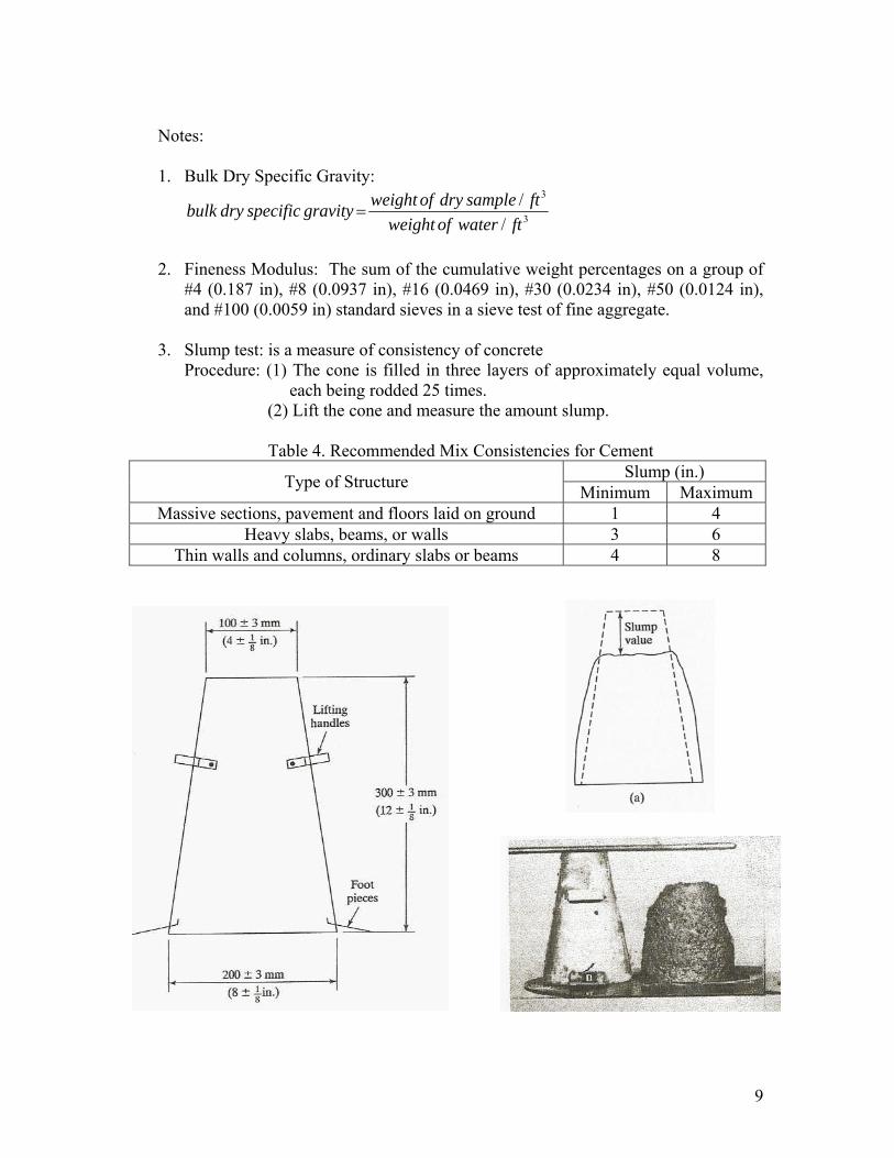
9
Notes: 1. Bulk Dry Specific Gravity:
3
3
//
ftwaterofweightftsampledryofweightgravityspecificdrybulk =
2. Fineness Modulus: The sum of the cumulative weight percentages on a group of
#4 (0.187 in), #8 (0.0937 in), #16 (0.0469 in), #30 (0.0234 in), #50 (0.0124 in), and #100 (0.0059 in) standard sieves in a sieve test of fine aggregate.
3. Slump test: is a measure of consistency of concrete
Procedure: (1) The cone is filled in three layers of approximately equal volume, each being rodded 25 times.
(2) Lift the cone and measure the amount slump.
Table 4. Recommended Mix Consistencies for Cement Slump (in.) Type of Structure Minimum Maximum
Massive sections, pavement and floors laid on ground 1 4 Heavy slabs, beams, or walls 3 6
Thin walls and columns, ordinary slabs or beams 4 8

10
4. The air-entrained concrete:
The air-entrained concrete is always used during the freezing months. The entrainment provides the capacity to absorb the expansive forces of ice that form within the concrete. The air-entrained concrete can have lower water-cement ratios than non-air-entrained concrete.
5. Reference: “Materials for Civil & Highway Engineers,” 2nd edition, Kenneth N.
Derucher and George P. Korfiatis, Prentice Hall, 1988, ISBN: 0-13-560509-1.
Table 1:

11
Table 2:

12
Table 3:

Steal Testing
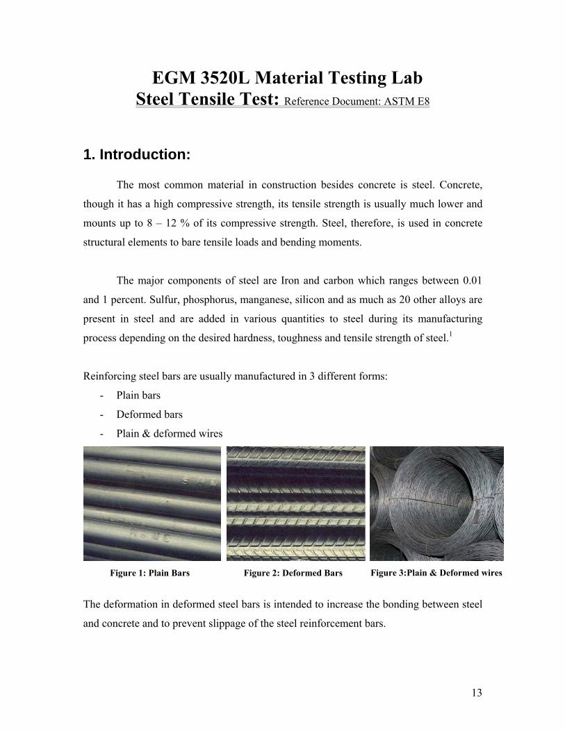
13
EGM 3520L Material Testing Lab Steel Tensile Test: Reference Document: ASTM E8
1. Introduction: The most common material in construction besides concrete is steel. Concrete,
though it has a high compressive strength, its tensile strength is usually much lower and
mounts up to 8 – 12 % of its compressive strength. Steel, therefore, is used in concrete
structural elements to bare tensile loads and bending moments.
The major components of steel are Iron and carbon which ranges between 0.01
and 1 percent. Sulfur, phosphorus, manganese, silicon and as much as 20 other alloys are
present in steel and are added in various quantities to steel during its manufacturing
process depending on the desired hardness, toughness and tensile strength of steel.1
Reinforcing steel bars are usually manufactured in 3 different forms:
- Plain bars
- Deformed bars
- Plain & deformed wires
Figure 1: Plain Bars Figure 2: Deformed Bars Figure 3:Plain & Deformed wires
The deformation in deformed steel bars is intended to increase the bonding between steel
and concrete and to prevent slippage of the steel reinforcement bars.

14
Steel reinforcement bars are produced mainly with four different yield strengths, shown
in the table below. The grade of steel indicates its yield strength in Ksi.
Type σyield (psi) σyield (MPa) Grade
Type1 40,000 300 40
Type 2 50,000 350 50
Type 3 60,000 400 60
Type 4 75,000 500 75 Table 1: Reinforcement Steel Strength
2. Objectives The objective of this lab experiments is to incrementally load a steel bar till
failure, while recording the value of the load and the change in length of the steel bar at
each stage. Then based on the colleted data, determine:
- Modulus of Elasticity of Steel, Esteel & Compare it to the theoretical value.
- Yield strength of Steel, σyield
- Ultimate strength of steel, σUltimate
- Plot Stress Vs Strain Curve for steel
3. Definitions - Yield Point: The Point at which an increase in strain occurs without an increase in
the stress is defined as the yield point. Stress at this point is defined as the steel
yield stress.1
4. Equipment - Universal Testing Machine
- Dial Gauge / Extensometer
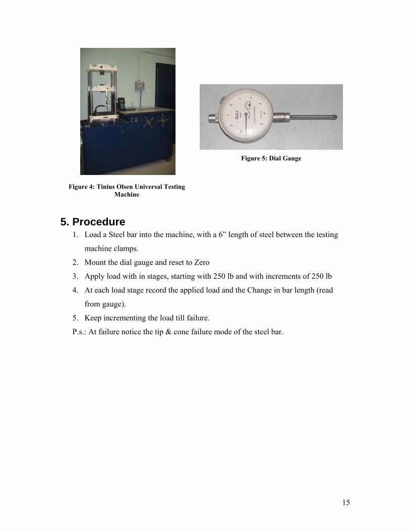
15
Figure 4: Tinius Olsen Universal Testing
Machine
Figure 5: Dial Gauge
5. Procedure 1. Load a Steel bar into the machine, with a 6” length of steel between the testing
machine clamps.
2. Mount the dial gauge and reset to Zero
3. Apply load with in stages, starting with 250 lb and with increments of 250 lb
4. At each load stage record the applied load and the Change in bar length (read
from gauge).
5. Keep incrementing the load till failure.
P.s.: At failure notice the tip & cone failure mode of the steel bar.

16
6. Equations:
( )
%100%
1029
.........
"64
6,
321
2
xE
EEError
psixEm
EEEEE
EEorSlopeE
LdAELA
P
lTheoretica
lTheoreticaalExperiment
SteellTheoretica
mave
avealExperimentalExperiment
−=
=
++++=
=∆∆
=
==∆∆
====
εσ
πεσ
εσδεσ

17
7. Typical Stress – Strain Curve
8. Calculation Sheet
P (lb) δ (in) σ (psi) ε E (psi) 250 δ1 σ1 ε1 E1
500 δ2 σ2 ε2 E2
750 δ3 σ3 ε3 E3
…. …. …. …. …. …. …. …. …. …. …. …. …. …. …. …. …. …. …. …. Pm δm (PL) σm εm Em
…. …. …. …. N/A …. …. …. …. N/A …. …. …. …. N/A Pn-1 δn-1 σn-1 εn-1 N/A
Pn (Pmax) N/A σn (σmax) N/A N/A

18
9. Discussion Possible source of error: Slipping of the steel at the testing machine grips
Fig.7. Theoretical Stress-Strain diagram for typical ductile metal. Lab. Pictures:
Students performing tensile test Necking of the rebar before fracture
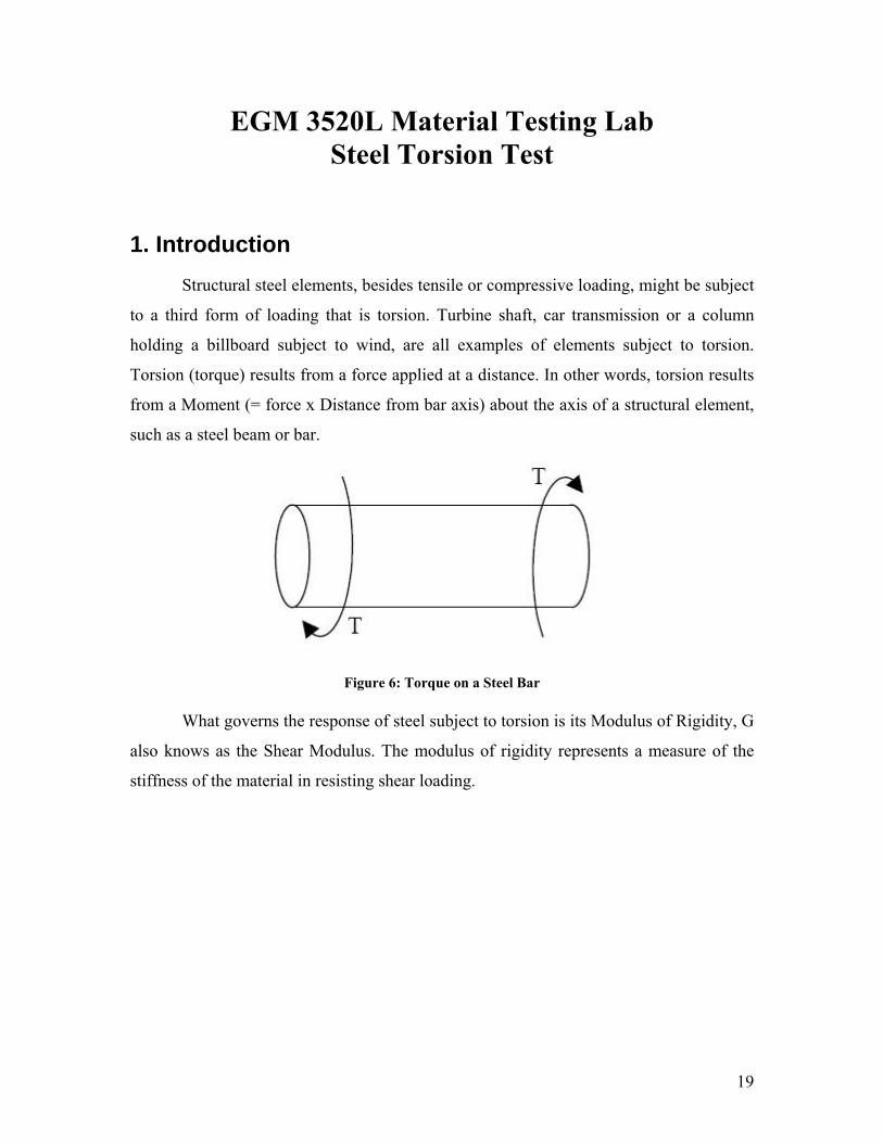
19
EGM 3520L Material Testing Lab Steel Torsion Test
1. Introduction Structural steel elements, besides tensile or compressive loading, might be subject
to a third form of loading that is torsion. Turbine shaft, car transmission or a column
holding a billboard subject to wind, are all examples of elements subject to torsion.
Torsion (torque) results from a force applied at a distance. In other words, torsion results
from a Moment (= force x Distance from bar axis) about the axis of a structural element,
such as a steel beam or bar.
Figure 6: Torque on a Steel Bar
What governs the response of steel subject to torsion is its Modulus of Rigidity, G
also knows as the Shear Modulus. The modulus of rigidity represents a measure of the
stiffness of the material in resisting shear loading.

20
Figure 7: Steel Test Specimen Before & After Being Subject to Torsion
2. Objectives
In this lab experiment two specimens will be used, a brass bar and a steel bar. The
dimensions of the bars are as follows:
- dSteel = dbrass = 0.24”
- Lsteet = Lbrass = 3.15”
Each specimen will be mounted on the Torque Testing Machine, and torque (T) will be
applied incrementally. Values of the Torque corresponding to each obtained rotation and
the angle of rotation Φ (measured using a dial gauge) will be recorded. The collected
values for each bar will be used to:
- Determine Modulus of Rigidity, G and compare it to the theoretical value of G
- Establish a relationship between T & Φ , and Plot T vs. Φ
- Establish a relationship between τ & γ , and Plot τ & γ
Where:
- G : Modulus of Rigidity, Psi
- Φ : Rotation, Degrees
- T: Applied torque (Moment),
lb-in
- τ: Shear Stress, Psi
- γ: Shear Strain

21
Figure 8: Sketch of Torsion Test Setup

22
3. Equipment - Torsion Testing Machine
- Dial Gauge
Figure 9: Torsion Testing Machine with bar specimens
4. Procedure 1. Load specimen to the machine
2. Reset Load (Zero Load) gage.
3. Reset Rotation Gage
4. Apply Torque incrementally to obtain desired value of Φ
5. Record values of T and Φ
6. Continue increasing T and recording T and Φ at each stage.
5. Equations
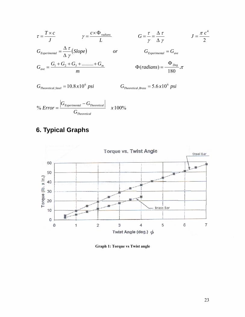
23
( )
%100%
106.5108.10
.180
)(.........
2
6,
6,
321
4
xG
GGError
psixGpsixG
radiansm
GGGGG
GGorSlopeG
cJGL
cJ
cT
lTheoretica
lTheoreticaalExperiment
BrasslTheoreticaSteellTheoretica
Degmave
avealExperimentalExperiment
radians
−=
==
Φ=Φ
++++=
=∆∆
=
=∆∆
==Φ×
=×
=
π
γτ
πγτ
γτγτ
6. Typical Graphs
Graph 1: Torque vs Twist angle
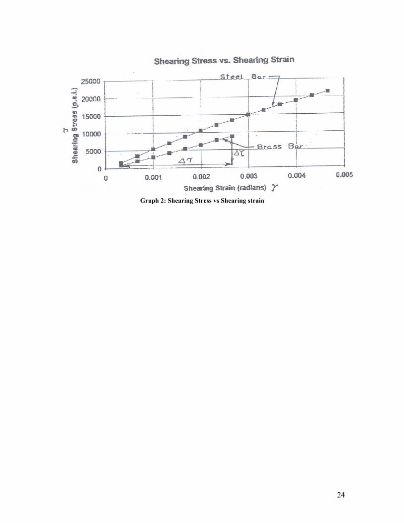
24
Graph 2: Shearing Stress vs Shearing strain
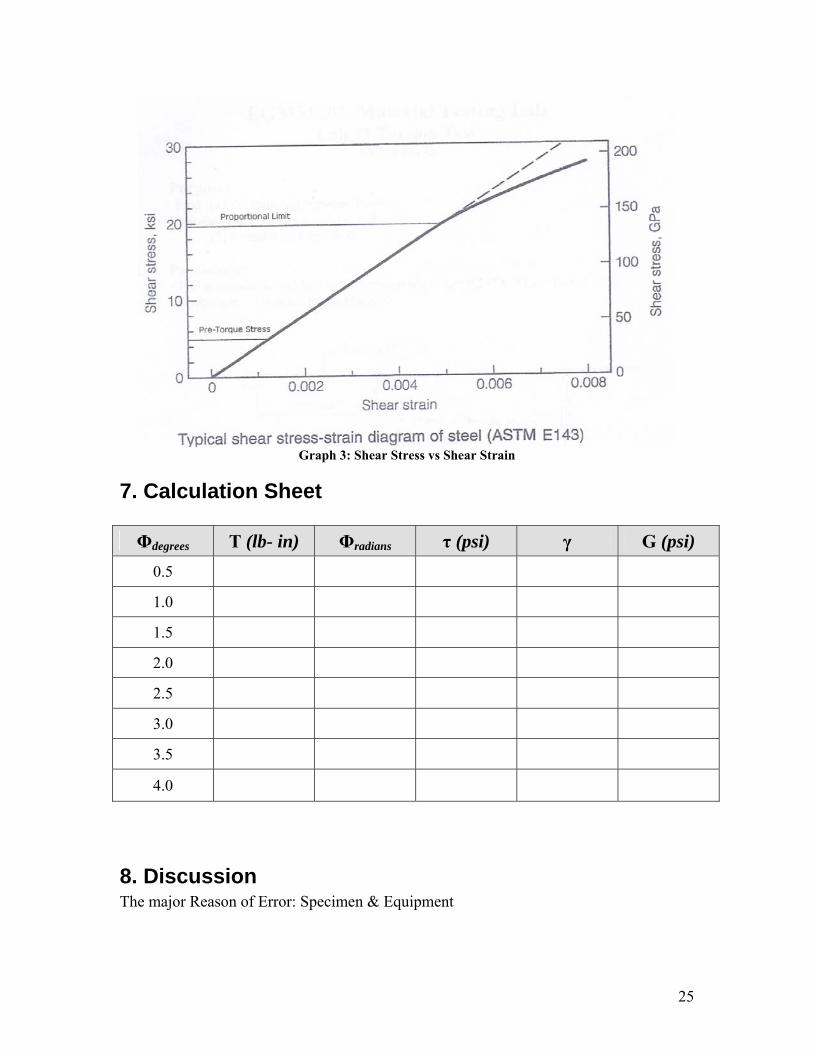
25
Graph 3: Shear Stress vs Shear Strain
7. Calculation Sheet Φdegrees T (lb- in) Φradians τ (psi) γ G (psi)
0.5
1.0
1.5
2.0
2.5
3.0
3.5
4.0
8. Discussion The major Reason of Error: Specimen & Equipment

26
EGM 3520L Material Testing Lab Steel Flexure Test
1. Introduction Beams subject to lateral loading exhibit a behaviour known as Flexure (Bending).
The sagging of a book shelf under the weight of the books is an example of flexure.
Under bending the beam experiences 3 types of loading; Compression in the top, tension
in the bottom in addition to shear in the direction of the lateral load. The compressive
force at the top with the tensile force at the bottom (thus forming a couple) creates what
is known as the bending moment.
The degree of flexure of the beam depends on four main factors. Those factors
are:
1. The applied load, as load increases the flexure increase
2. Moment of Inertia I of the beam, as the I increases we have less deflection.
3. The length of the beam. Longer spans result in larger deflections
4. The properties of the material making up the beam, mainly E
2. Objectives Two test specimens will be used. A brass and a cast iron specimen. The
specimens have the following dimensions:
Compression
Tension
Shear
Bending Moment
Shear
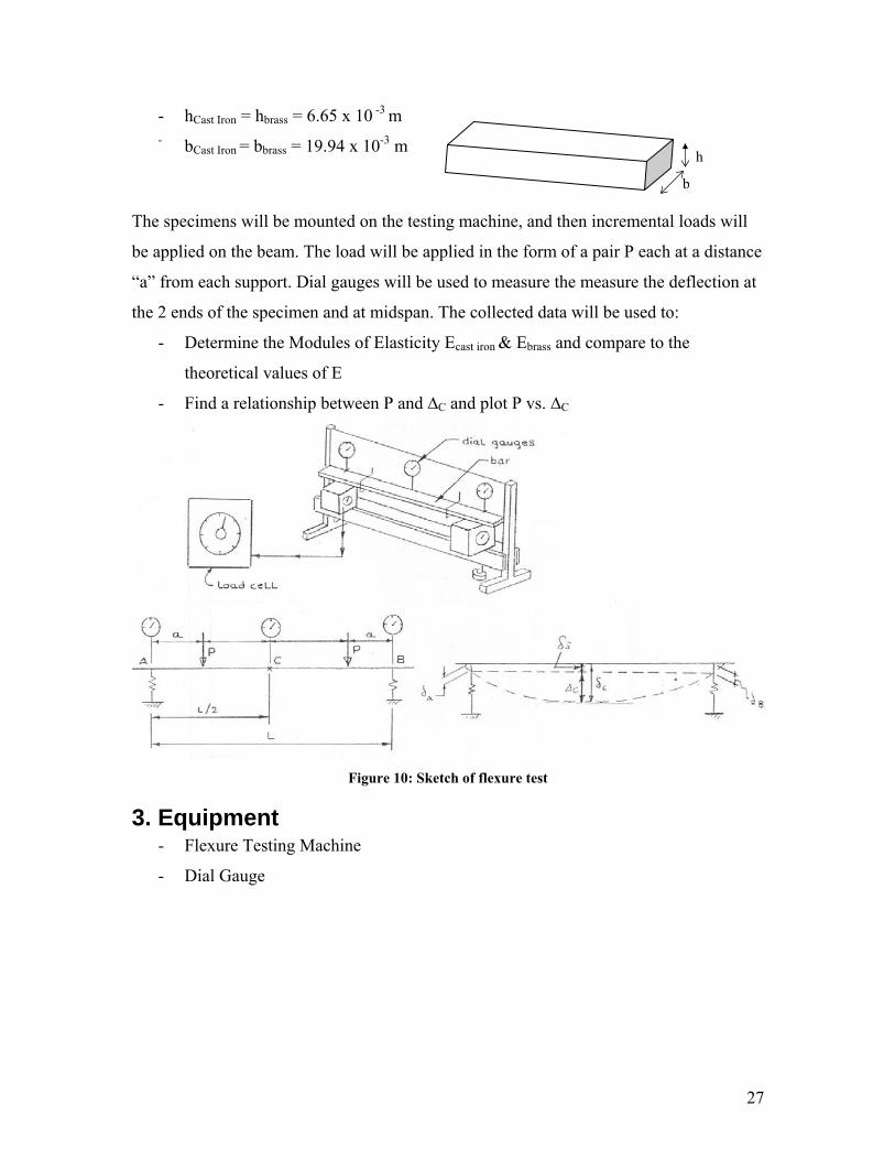
27
- hCast Iron = hbrass = 6.65 x 10 -3 m - bCast Iron = bbrass = 19.94 x 10⁻³ m
The specimens will be mounted on the testing machine, and then incremental loads will
be applied on the beam. The load will be applied in the form of a pair P each at a distance
“a” from each support. Dial gauges will be used to measure the measure the deflection at
the 2 ends of the specimen and at midspan. The collected data will be used to:
- Determine the Modules of Elasticity Ecast iron & Ebrass and compare to the
theoretical values of E
- Find a relationship between P and ∆C and plot P vs. ∆C
Figure 10: Sketch of flexure test
3. Equipment - Flexure Testing Machine
- Dial Gauge
h
b
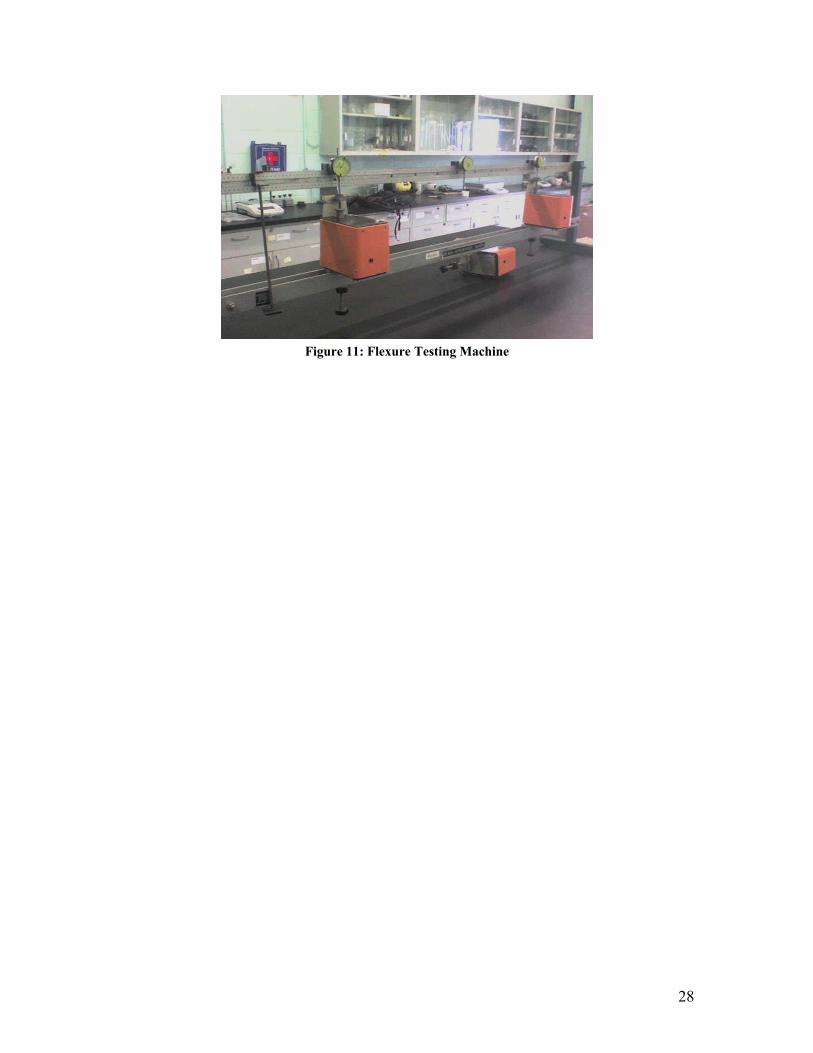
28
Figure 11: Flexure Testing Machine

29
4. Procedure 1. Mount specimen on flexure testing machine
2. Reset dial gauges (3 dials)
3. Apply 2 loads of equal value P each at a distance “a” from each support (note
the value of “a” to use it in calculations)
4. Incrementally increase load (refers to the indicate loads in the worksheet
below)
5. For each load record the readings of the vertical deflections measured by the
dial gauges at the specimen ends and midspan.
5. Equations
( ) ( )
%100%
105165
.........
25.0124
43.24
43.
121
2
,,
321
2222
3
xE
EEError
GPaGGPaG
mEEEEE
mamLI
aLaPEorEI
aLaP
bhI
lTheoretica
lTheoreticaalExperiment
BrasslTheoreticaIronCastlTheoretica
mave
CC
SCCBA
S
−=
==
++++=
==∆−
=−
=∆
=−=∆+
= δδδδδ
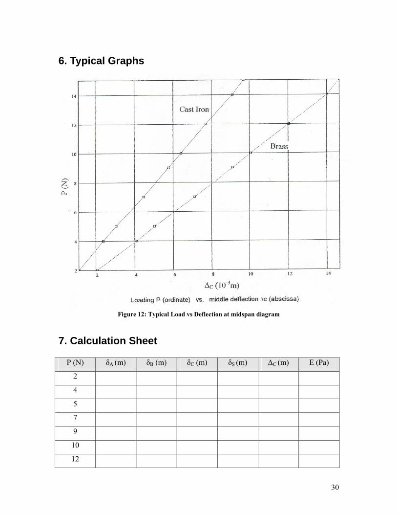
30
6. Typical Graphs
Figure 12: Typical Load vs Deflection at midspan diagram
7. Calculation Sheet
P (N) δA (m) δB (m) δC (m) δS (m) ∆C (m) E (Pa)
2
4
5
7
9
10
12
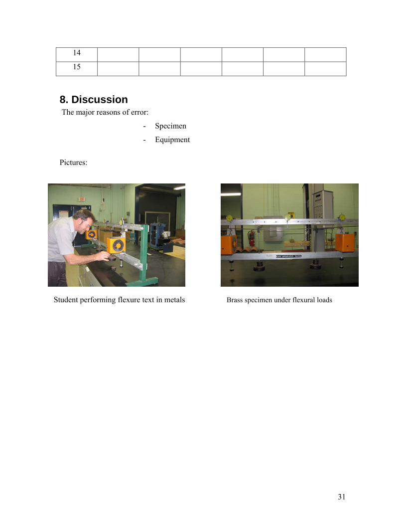
31
14
15
8. Discussion The major reasons of error:
- Specimen
- Equipment
Pictures:
Student performing flexure text in metals Brass specimen under flexural loads

Wood Testing

40
EGM3520L Material Testing Lab Column Buckling Test
Introduction: A buckling load is defined as a critical load or crippling load or Euler’s load on a slender column, which just causes buckling or bending of a compression member. Thus, the nature of compressive force is no more axial in buckling phenomena. Objective: The main objective is to find theoretical and practical value of buckling load in timber compression members. By performing this lab students will find: the relationship between σ and ε plotting the data obtained and based on the graph identify the proportional Limit (PL), modulus of elasticity E, ultimate strength (US), and the relationship between the maximum compressive stress (FC
') and the slenderness ratio (L/d). Procedure: Five slender specimens of timber (Southern Pine) are prepared with different square section as follow; sizes (d x d x L): 3"x3"x12", 1.5"x1.5x12", 1"x1"x12", ¾"x¾""x12", and ½"x½"x12". Then they are tested one by one to find out its buckling load. Compressive load is applied slowly on the column specimen until it just starts to buckle and the load is recorded to compare for theoretical value. Theoretically,
Buckling load= Pcr=π2EI/ (Le) 2
Where, E= elastic modulus of the specimen I= I min= second moment of area (moment of inertia) Le= effective length of column depending on the end condition (in our case, two ends are fixed and hence ‘Le ‘will be ‘1.0L’ and L= length of column.

41
Specimen: Timber slender member with size (bxdx) =1”x3”x12”, Equipment: Compression testing machine with load dial gauge.
Result:
Tables: 3"x3"x12" P (lb) δ (0.001 in) σ (psi) ε E (psi)
1000 δ1 σ1 ε1 E1 2000 δ2 σ2 ε2 E2 3000 δ3 σ3 ε3 E3 ּּּּּ ּּּּּ ּּּּּ ּּּּּ ּּּּּ ּּּּּ ּּּּּ ּּּּּ ּּּּּ ּּּּּ ּּּּּ ּּּּּ ּּּּּ ּּּּּ ּּּּּ
Pm δm (PL) σm εm Em ּּּּּ ּּּּּ ּּּּּ ּּּּּ N/A ּּּּּ ּּּּּ ּּּּּ ּּּּּ N/A ּּּּּ ּּּּּ ּּּּּ ּּּּּ N/A Pn-1 δn-1 σn-1 εn-1 N/A
(Pmax) Pn N/A (σmax=US) σn N/A N/A
Pmax (lb) A (in2) FC' (Pmax/A) (psi) L/d
(Pmax)1 9 (FC')1 4
(Pmax)2 A2 (FC')2 8
(Pmax)3 A3 (FC')3 12
(Pmax)4 A4 (FC')4 16
(Pmax)5 A5 (FC')5 24

42
Equations:
σ = P/A, ε = δ/L, E = σ/ε = ∆σ/∆ε, A = d2, L = 12"
Eexperimental = ∆σ/∆ε (slope) or Eexperimental = Eave
Eave = (E1 + E2 + E3 + ⋅⋅⋅⋅⋅ + Em) / m, (Etheoretical)W =
1.3x10⁶ psi
Error (%) = | (Eexperimental – Etheoretical) / Etheoretical | x 100%, FC' =
Pmax/A
Figures:

43
Discussion: It is aimed to be familiar with the buckling load which mainly depends on the modulus of elasticity, moment of inertia of the section, and end condition of the compression member. Possible error may develop due to inferior material quality, eye judgment of buckling and its corresponding load. The major reason of the error: knots, split, and uneven surface.

Bitumen Testing

57
1. 2.
SPECIFIC GRAVITY TEST FOR BITUMEN
Theorv and Scope: The density of a bitumen binder is a fundamental property frequently used as an aid in
classifying the binders for use in paving jobs. In most applications, the bitumen is weighed, but finally
in use with aggregate system, the bitumen content is converted on volume basis. Thus an accurate
density value is required for conversion of weight to volume. The specific gravity is greatly influenced
by the chemical composition of binder. Increased amount of aromatic type compounds cause an
increase in the specific gravity.
The specific gravity is defined by ISI as the ratio of the mass of a given volume of the
bituminous material to the mass of an equal volume of water, the temperature of both being specified at
27°C±O.1 °C.
The code of practice used to determine the specific gravity is IS: 1202.
Aim: To determine the Specific gravity of given Bituminous material.
Apparatus: There are two methods. 1) Pyknometer Method, 2) Balance Method. Pyknometer Method:
Specific gravity Bottle, Balance and Distilled water.
Procedure:
~ The clean, dried specific gravity bottle is weighed let that be W Igm.
~ Then it is filled with fresh distilled water and then kept in water bath for at least half an hour at
temperature 27°C±O.1 °C.
~ The bottle is then removed and cleaned from outside. The specific gravity bottle containing
distilled water is now weighed. Let this be W 2gm.
~ Then the specific gravity bottle is emptied and cleaned. The bituminous material is heated to a
pouring temperature and the material is poured half the bottle, by taking care to prevent entry
of air bubbles. Then it is weighed. Let this be W 3gm.
~ The remaining space in specific gravity bottle is filled with distilled water at 27°C and is
weighed. Let this be W 4gm. Then specific gravity of bituminous material is given by formula
(~ -~) (~-~)-(~ -~)
Observation and Calculation:
Result: The specific gravity of given bituminous binder is ___________________ _
Viva Voce: 1. Define specific gravity.
2. What is the use of finding specific gravity?
3. What are the factors affecting specific gravity test?
References:
1. Indian Standard Method for Tar and Bitumen, Determination of Specific Gravity of
Bitumen, IS: 1202, Indian Standards Institution.
2. Indian Standard Specification for Paving Bitumen, IS: 73.
3. S.K. Khanna and C.E.G Justo, Highway Materials Testing Laboratory Manual, Nem
Chand Bros. Roorkee.

1. 2.
PENETRATION TEST Theorv and Scope:
The consistencies of bituminous materials vary depending upon several factors such as
constituents, temperature, etc. As temperature ranges between 25° and 50°C most of the paving
bitumen grades remain in semi solid or in plastic states and their viscosity is so high that they do not
flow as liquid.
Determination of absolute viscosity of bituminous material is not so simple. Therefore the
consistency of these materials is determined by indirect methods. The consistency of bitumen is
determined by penetration test which is a very simple test. Various types and grades of bituminous
materials are available depending on their origin and refining process. The penetration test determines
the consistency of these materials foe the purpose of grading them, by measuring the depth (in units of
one tenth of a millimeter or one hundredth of a centimeter) to which a standard needle will penetrate
vertically under specified conditions of standard load, duration and temperature. Thus the basic
principle of the penetration test is the measurement of the penetration (in units of one tenth of a mm) of
a standard needle in a bitumen sample maintained at 25C during five seconds, the total weight of the
needle assembly being 100gm. The softer the bitumen, the greater will be the penetration. The test is
conducted as per IS-1203 for paving bitumen.
Aim: To determine the grade of a given binder.
Apparatus: It consists of items like container, needle, water bath, penetrometer, stop watch etc.
Container is 55mm in diameter and 35mm to 57mm height. The needle is provided with a
shank approximately 3.0mm in diameter into which it is immovably fixed.

Procedure:
~ The bitumen is softened to a paving consistency between 75° and 100°C above the approximate
temperature at which bitumen softens.
~ The sample material is thoroughly stirred to make it homogeneous and free from air bubbles and
water.
~ The sample containers are cooled in atmosphere of temperature not lower than 13°C for one
hour. Then they are placed in temperature controlled water bath at a temperature of 25°C for a
period of one hour.
~ The weight of needle, shaft and additional weight are checked. The total weight of this assembly
should be IOOgm.
~ Using the adjusting screw, the needle assembly is lowered and the tip of the needle is made to
just touch the top surface of the sample.
~ The needle assembly is clamped in this position. The contact of the tip of the needle is checked
using the mirror placed on the rear of the needle.
~ The initial reading of the penetrometer dial is either adjusted to zero or the initial reading is
noted.
~ Then the needle is released by pressing a button and a stop watch is started. The needle is
released exactly for a period of 5.0secs.
~ At least 3 measurements are made on this sample by testing at distance of not less than IOOmm
apart.
~ The difference between the initial and final penetration readings are taken as the
penetration value.
Penetration Test Concept
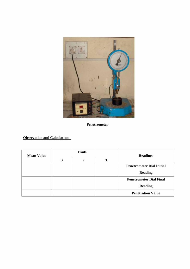
Penetrometer
Observation and Calculation:
Trails Readings Mean Value
1 2 3 Penetrometer Dial Initial
Reading
Penetrometer Dial Final
Reading
Penetration Value

Result: The average penetration value of a given bitumen sample is __________________ and the grade of
bitumen is
Viva Voce: 1. What are the applications of penetration test?
2. What do you understand by the term 30/40 bitumen?
3. What are the precautions to be taken while conducting a penetration test?
References:
1. Indian Standard Method for Tar and Bitumen, Determination of Penetration of Bitumen, IS:
1203, Indian Standards Institution.
2. Indian Standard Specification for Paving Bitumen, IS: 73.
3. S.K. Khanna and C.E.G Justo, Highway Materials Testing Laboratory Manual, Nem
Chand Bros. Roorkee.
2.
DUCTILITY TEST Theorv and Scope:
A certain minimum ductility is necessary for a bitumen binder. This is because of the
temperature changes in bituminous mixes and the repeated deformations that occur in flexible
pavements due to the traffic loads. It is of significant importance that the binders form ductile thin films
around the aggregates. The binder material which does not possess sufficient ductility would crack and
thus provide previous pavement surface. This is in turn results in damaging effect to the pavement
structure. The ductility is expressed as the distance in centimeters to which a standard briquette of
bitumen can be stretched before the thread breaks. The test is standardized by the IS: 1208. The test is
conducted at 27°±O.5°C and a rate of pull of 50±2.5 mm per minute.
Aim: To conduct ductility test on given bitumen sample.
Apparatus: Briquette mould, (length - 75mm, distance between clips - 30mm, width at mouth of clips
- 20mm, cross section at minimum width - lOmm x lOmm), Ductility machine with
water bath and a pulling device at a precaliberated rate, a putty knife, thermometer.
Procedure:
~ The bitumen sample is method to a pouring temperature (75°C to 100°C) and poured into the
mould assembly and placed on a brass plate, where a solution of glycerin or soap solution is
applied at all surfaces of briquette mould exposed to bitumen.
~ After the sample is poured to the mould, thirty to forty minutes the entire assembly is placed in a
water bath at 27°C.
~ Then the sample is removed from the water bath maintained at 27°C and excess bitumen material
is cutoffby leveling the surface using hot knife.
~ After trimming the specimen, the mould assembly containing sample is replaced in water bath
maintained at 27°C for 85 to 95 minutes. Then the sides of mould are removed and

the clips are carefully booked on the machine without causing any initial strain. Two or more
specimens may be prepared in the moulds and clipped to the machine so as to conduct these test
simultaneously.
~ The pointer is set to read zero. The machine is started and the two clips are thus pulled apart
horizontally.
~ While the test is in operation, it is checked whether the sample is immersed in water at depth of
atleast IOmm. The distance at which the bitumen thread of each specimen breaks is recorded
(in em) to report as ductility value. L.en~Ul . Distance betw~n dip~ Willtn, at mouth of ol'illS ill CTO~~ ~~ctiol'l ;J.l minimum. widtll •
75 mm Xl mr!:l :2() mID
[{I mm ;< 10 rom
Ductility Test Concept
Sample Prepared in Briquette Mould and Ductility Apparatus
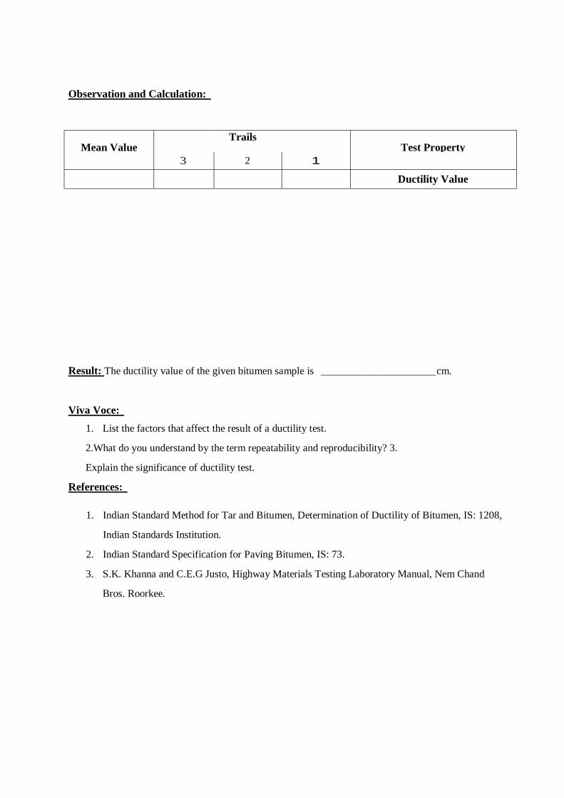
Observation and Calculation:
Trails Test Property Mean Value
1 2 3
Ductility Value
Result: The ductility value of the given bitumen sample is ______________________ cm.
Viva Voce: 1. List the factors that affect the result of a ductility test.
2.What do you understand by the term repeatability and reproducibility? 3.
Explain the significance of ductility test.
References:
1. Indian Standard Method for Tar and Bitumen, Determination of Ductility of Bitumen, IS: 1208,
Indian Standards Institution.
2. Indian Standard Specification for Paving Bitumen, IS: 73.
3. S.K. Khanna and C.E.G Justo, Highway Materials Testing Laboratory Manual, Nem Chand
Bros. Roorkee.

SOFTENING POINT OF BITUMEN
Theorv and Scope:
Bitumen does not suddenly change from solid to liquid state, but as the temperature increase, it
gradually becomes soften until it flows readily. The softening point is the temperature at which the
substance attains particular degree of softening under specified condition of test. For bitumen it is
usually determined by Ring and Ball apparatus. The test is conducted as per IS: 1205.
Aim: To determine the softening point of given paving bitumen as per IS: 1205.
Apparatus: Ring and Ball apparatus, Water bath with stirrer, Thermometer, Glycerin, etc. Steel balls
each of9.5mm and weight of2.5±0.08gm.
Procedure:
~ Sample material is heated to a temperature between 75° and 100°C above the approximate
softening point until it is completely fluid and is poured in heated rings placed on the metal
plate.
~ To avoid sticking of the bitumen to metal plate, coating is done to this with a solution of glycerin
and dextrin.
~ After cooling the rings in air for 30 minutes, the excess bitumen is trimmed and rings are placed
in the support.
~ At this time the temperature of distilled water is kept at 5°C. This temperature IS maintained for
15 minutes after which the balls are placed in position.
~ Then the temperature of water is raised at uniform rate of 5°C per minute with a controlled
heating unit, until the bitumen softens and touches the bottom plate by sinking of balls. At least
two observations are made. For material whose softening point is above 80°C, glycerin is used
for heating medium and the starting temperature is 35°C instead of 5°C.

~ The temperature at the instant when each of the ball and sample touches the bottom plate of
support is recorded as softening point value.
Softening Test Concept
Softening Point Apparatus and Ring and Ball Guides
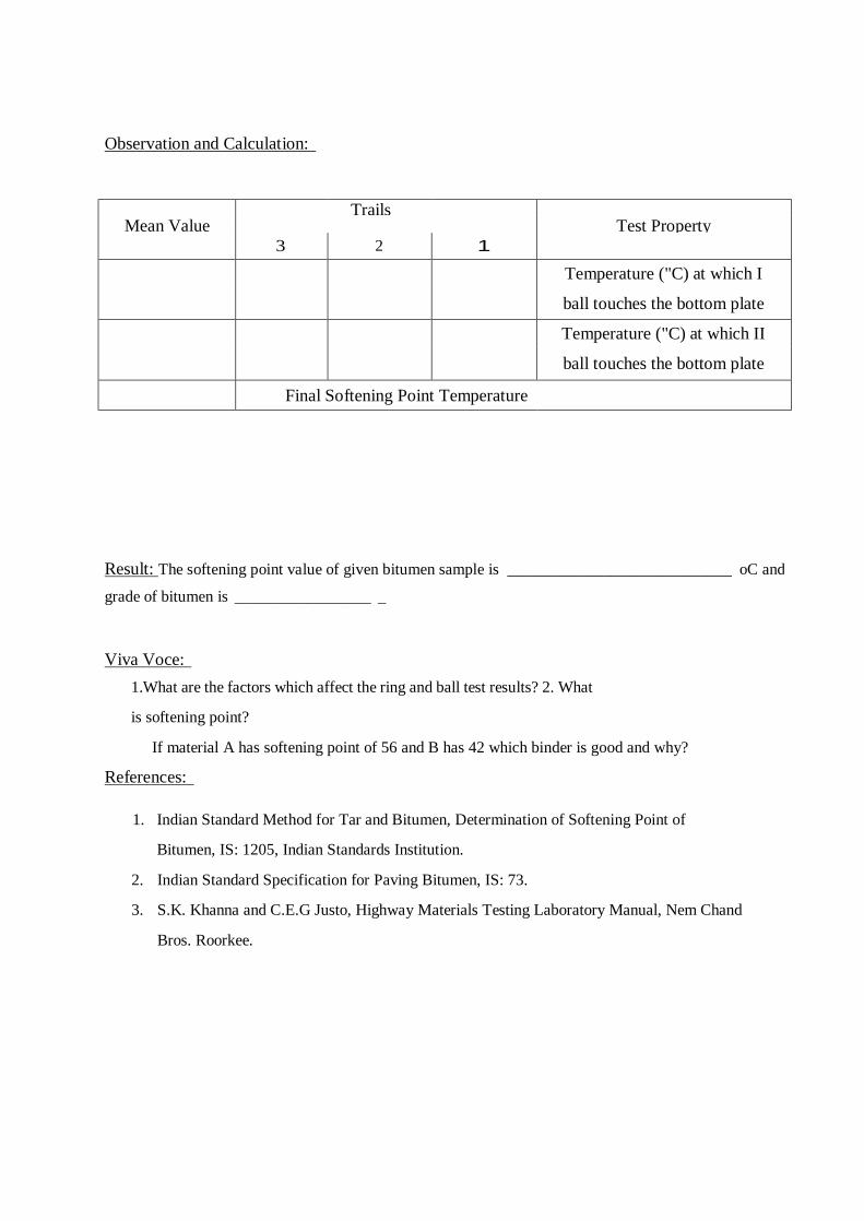
Observation and Calculation:
Trails Test Property Mean Value
1 2 3
Temperature ("C) at which I
ball touches the bottom plate
Temperature ("C) at which II
ball touches the bottom plate
Final Softening Point Temperature
Result: The softening point value of given bitumen sample is ____________________________ oC and
grade of bitumen is _________________ _
Viva Voce: 1.What are the factors which affect the ring and ball test results? 2. What
is softening point?
If material A has softening point of 56 and B has 42 which binder is good and why?
References:
1. Indian Standard Method for Tar and Bitumen, Determination of Softening Point of
Bitumen, IS: 1205, Indian Standards Institution.
2. Indian Standard Specification for Paving Bitumen, IS: 73.
3. S.K. Khanna and C.E.G Justo, Highway Materials Testing Laboratory Manual, Nem Chand
Bros. Roorkee.

77 78
Concrete and Highway Materials Testing Laboratory
FLASH AND FIRE POINT TEST
Theorv and Scope:
Flash and Fire point test is a safety test conducted on a bituminous material so that it gives an
indication of the critical temperature at and above where precautions should be taken to eliminate fire
hazards during its applications. Bituminous materials leave out volatiles at high temperature depending
upon their grade. These volatile vapors catch fire causing a flash. This condition is very hazardous and
it is therefore essential to qualifY this temperature for each bitumen grade, so that the paving engineers
may restrict the mixing or application temperature well within the limits. Flash and Fire point test is
conducted as per IS: 1209.
As per IS: 1209 the definitions of flash and fire point are:
Flash Point: "The flash point of a material is the lowest temperature at which the vapour of substance
momentarily takes fire in the form of a flash under specified conditions of test".
Fire Point: "The fire point is the lowest temperature at which the material gets ignited and burns under
specified condition of test".
Aim: To determine the flash and fire point of a given bituminous material.
Apparatus: Pensky-Martens closed cup tester, thermometer, heating source, flame exposure.
Procedure:
~ All parts of the cup are cleaned and dried thoroughly before the test is started.
~ The material is filled in the cup upto a mark. The lid is placed to close the cup in a closed system.
All accessories including thermometer of the specified range are suitably fixed.
~ The bitumen sample is then heated. The test flame is lit and adjusted in such a way that the size of
a bed is of 4mm diameter. The heating of sample is done at a rate of 5° to 6°C per minute.
During heating the sample the stirring is done at a rate of approximately 60 revolutions per
minute.

~ The test flame is applied at intervals depending upon the expected flash and fire points and
corresponding temperatures at which the material shows the sign of flash and fire are noted.
Flash and Fire Point Test Concept
Flash and Fire Point Test in Progress
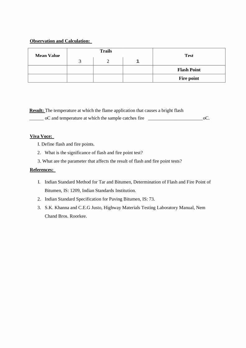
Observation and Calculation:
Trails Test Mean Value
1 2 3
Flash Point
Fire point
Result: The temperature at which the flame application that causes a bright flash ______ oC and temperature at which the sample catches fire _______________________ oC.
Viva Voce: I. Define flash and fire points.
2. What is the significance of flash and fire point test?
3. What are the parameter that affects the result of flash and fire point tests?
References:
I. Indian Standard Method for Tar and Bitumen, Determination of Flash and Fire Point of
Bitumen, IS: 1209, Indian Standards Institution.
2. Indian Standard Specification for Paving Bitumen, IS: 73.
3. S.K. Khanna and C.E.G Justo, Highway Materials Testing Laboratory Manual, Nem
Chand Bros. Roorkee.

VISCOSITY TEST Theorv and Scope:
Viscosity is defined as the increase of fluidity. The degree of fluidity at the application
temperature greatly influences the ability of bituminous material to spread, penetrate in to void and
also coat the aggregates and hence affects the strength characteristics of the resulting paving mixes.
There is an optimum value of fluidity or viscosity for mixing and compacting for each aggregate
gradation of the mix and bitumen grade. At high fluidity or low viscosity, the bitumen binder simply
"lubricates" the aggregate particles instead of providing a uniform film thickness for binding action.
Similarly, low fluidity or high viscosity does not enable the bitumen to coat the entire surface of
aggregates. It will increase the compactive force or effort. The test is conducted as per IS: 1206.
Aim: To determine the property of a given bituminous material as per IS: 1206.
Apparatus: A orifice viscometer (one of 4.0mm diameter used to test cut back grades 0 and 1 and
10mm orifice to test all other grades), water bath, stirrer and thermometer.
Procedure:
~ The tar cup is properly leveled and water in the bath is heated to the temperature specified for the
test and is maintained throughout the test.
~ The sample material is heated at the temperature 20 above the specified test temperature and the
material is allowed to cool. During cooling the material continuously, stirred.
~ When material reaches slightly above test temperature, the same is poured in the tar cup, until the
leveling peg on the value rod is just immersed.
~ A graduate receiver (cylinder) and a 20ml of mineral oil or one percent by weight solution of soft
soap is poured.
~ When the sample material reaches the specified test temperature within ±O.I°C and then valve is
opened.

~ The stop watch is started with the valve opening and time is noted for collecting a 50ml of test
sample to flow through the orifice and collected in the receiver kept below the orifice
viscometer.
L.
r T o
Schematic Representation of Experiment
-..,...
Standard Tar Viscometer
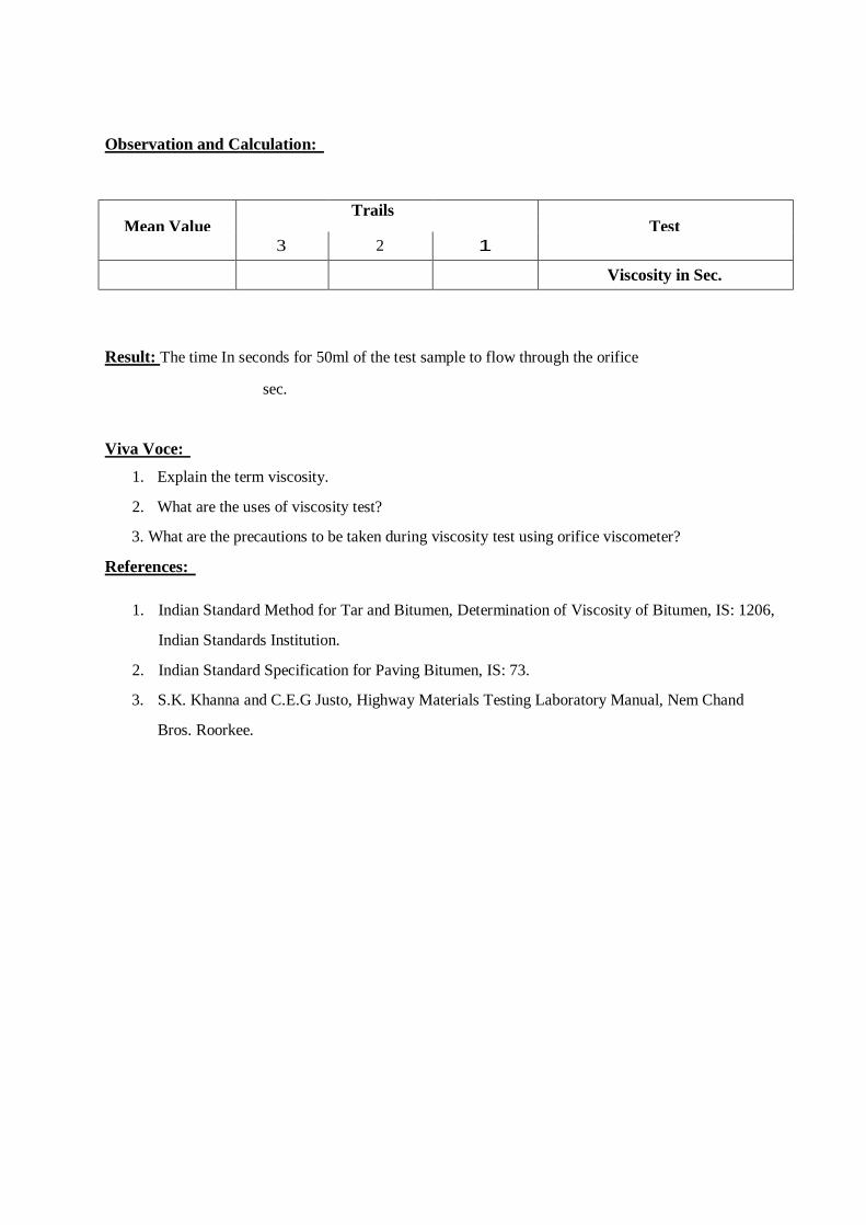
Observation and Calculation:
Trails Test Mean Value
1 2 3
Viscosity in Sec.
Result: The time In seconds for 50ml of the test sample to flow through the orifice
sec.
Viva Voce: 1. Explain the term viscosity.
2. What are the uses of viscosity test?
3. What are the precautions to be taken during viscosity test using orifice viscometer?
References:
1. Indian Standard Method for Tar and Bitumen, Determination of Viscosity of Bitumen, IS: 1206,
Indian Standards Institution.
2. Indian Standard Specification for Paving Bitumen, IS: 73.
3. S.K. Khanna and C.E.G Justo, Highway Materials Testing Laboratory Manual, Nem Chand
Bros. Roorkee.
Bituminous Mix Desien bv Marshall Method Theorv and Scope:
Bituminous mixes are used in the surface course of road and airfield pavements. The desirable
bituminous mix properties include stability, density, durability, flexibility, resistance to skidding and
workability during construction. Stability is defined as resistance of the paving mix to deformation
under load and is thus a stress level which causes strain depending upon anticipated field conditions.
Stability is function of friction and cohesion. Durability is defined as the resistance of the mix against
weathering which causes hardening and this depends upon loss of volatiles and oxidation.
In this method the resistance to plastic deformation of cylindrical specimen of bituminous
mixture is measured when the same is loaded at the periphery at 5 cm per minute. This test procedure is
used in designing and evaluating bituminous paving mixes. ASTM vide designation D 1559-62 T has
standardized the test procedure.
Aim: To determine optimum binder content of given bituminous mix by Marshall method of Mix
Design.
Apparatus: Mould Assembly, Sample Extractor, Compaction Pedestal and Hammer, Breaking Head,
Loading Machine, flow meter, thermometers, water bath and oven.
Procedure: ~ The coarse aggregates, fine aggregates and mineral filler material should be proportioned and
mixed in such a way that final mix after blending has the gradation within the specified
range.
~ Approximately 1200 grms of aggregates and filler are taken and heated to a temperature of
175° to 190° C.
~ The compaction mould assembly and rammer are cleaned and kept pre-heated to a temperature
of 100°C to 145°C. The bitumen is heated to temperature of 121 ° to 138° C

and the required quantity of first trail percentage of bitumen is added to the heated aggregate and
thoroughly mixed using a mechanical mixer or by hand mixing with trowel.
~ Then the mix is heated and a temperature of 150° to 160°C is maintained and then the mix is
transferred into the pre-heated mould and compacted by giving seventy five blows on each side.
~ The specific gravity values of different aggregates, filler and bitumen used are determined first.
The theoretical specific gravity of the mix is determined.
~ Soon after the compacted bituminous mix specimens have cooled to room temperature, the weight,
average thickness and diameter of the specimen are noted. The specimens are weighed in air and
then in water.
~ The bulk density value of the specimen if calculated from weight and volume.
~ Then the specimen to be tested are kept immersed under water in a thermostatically controlled
water bath maintained at 60° ± 1 ° C for 30 to 40 minutes.
~ The specimens are taken out one by one, placed in the Marshall test head and the Marshall stability
value and flow value are noted.
~ The corrected Marshall Stability value of each specimen is determined by applying the appropriate
correction factor, if the average height of the specimen is not exactly 63.5
mm.
~ Five graphs are plotted with values of bitumen content against the values of density, Marshall
Stability, Voids in total mix, Flow value, Voids filled by Bitumen.
~ Let the bitumen contents corresponding to maximum density be B 1, corresponding to maximum
stability be B2 and that corresponding to the specified voids content (at 4.0%) be B3. Then the
optimum bitumen content for mix design is given by: Bo= (B1+ B2+ B3) / 3
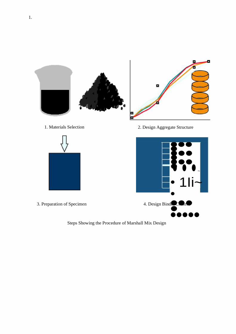
1.
1. Materials Selection
3. Preparation of Specimen
2. Design Aggregate Structure
•••• •••• •••• ~ ••• • 1Ii~ • •••• •••••
4. Design Binder Content
Steps Showing the Procedure of Marshall Mix Design
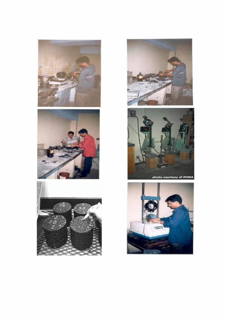
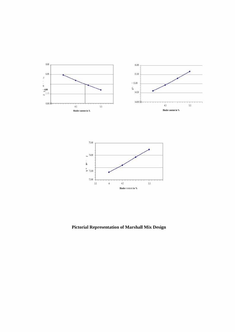
8.00 16.00
6.00 15.50 ;!. .9 ~ 4.00 ~ ~
~ 15.00
=" > 2.00 14.50
0.00 3.5 4.5 5.5
14.00 3.5 4.5 5.5
Binder content in !I. Binder content in %
75.00
74.00 ~ .S '" "" > 73.00
72.00 3.5 4 4.5 5.5
Binder rontent in %
Pictorial Representation of Marshall Mix Design

Observations and Calculations:
Result: The optimum binder content of the given mix is _____________________ _
Viva Voce: 1. What is the significance of flow value in Marshall Test?
2. What is filler?
3. What are the essential properties of bituminous mixes?
Reference:
1. S.K. Khanna and C.E.G Justo, Highway Materials Testing Laboratory Manual, Nem
Chand Bros. Roorkee.
2. Ministry of Road Highway Transport, fourth revisions, by Indian Road Congress.