material degradation problems - nguyen.hong.hai.free.frnguyen.hong.hai.free.fr/ebooks/science and...
TRANSCRIPT
21Material Degradation Problems
1 INTRODUCTION
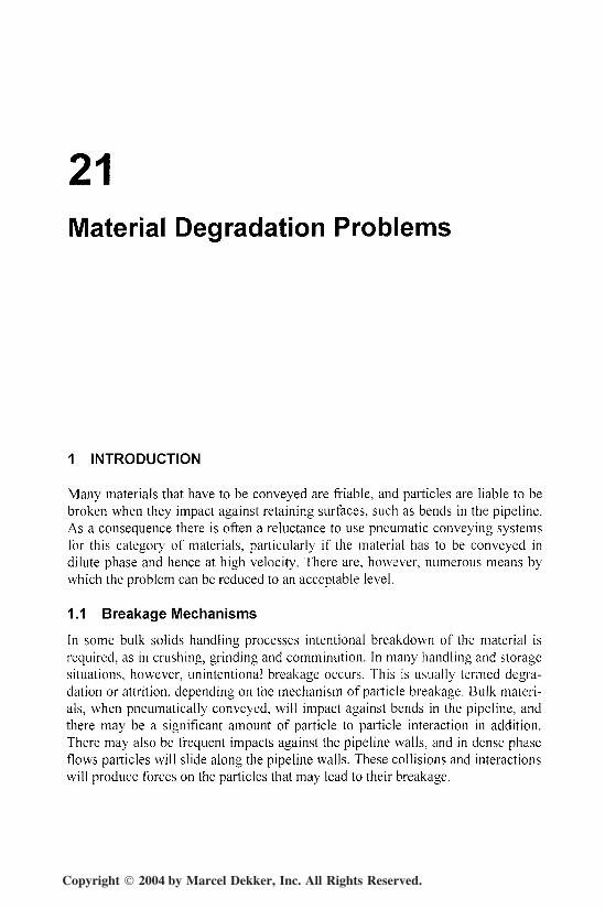
Many materials that have to be conveyed are friable, and particles are liable to bebroken when they impact against retaining surfaces, such as bends in the pipeline.As a consequence there is often a reluctance to use pneumatic conveying systemsfor this category of materials, particularly if the material has to be conveyed indilute phase and hence at high velocity. There are, however, numerous means bywhich the problem can be reduced to an acceptable level.
1.1 Breakage Mechanisms
In some bulk solids handling processes intentional breakdown of the material isrequired, as in crushing, grinding and comminution. In many handling and storagesituations, however, unintentional breakage occurs. This is usually termed degra-dation or attrition, depending on the mechanism of particle breakage. Bulk materi-als, when pneumatically conveyed, will impact against bends in the pipeline, andthere may be a significant amount of particle to particle interaction in addition.There may also be frequent impacts against the pipeline walls, and in dense phaseflows particles wil l slide along the pipeline walls. These collisions and interactionswill produce forces on the particles that may lead to their breakage.
Copyright 2004 by Marcel Dekker, Inc. All Rights Reserved.

604 Chapter 21
If particle breakdown occurs readily the bulk solid is said to be friable. Ten-dency to particle breakdown covers three main situations. The first is a tendency toshatter or degrade when the bulk solid is subject to impaction or compressive load-ing. The second is the tendency for fines and small pieces to be worn away byattrition when bulk solids either rub against each other or against some surface,such as a pipeline wall or bend. The third is the tendency for materials such asnylons and polymers to form angel hairs when conveyed, as a result of micro-melting occurring due to the particles sliding against pipeline walls.
1.2 Magnitude of Problem
Of all conveying systems, dilute phase probably results in more material degrada-tion and attrition than any other. This is because particle velocity is a major vari-able in the problem and, in dilute phase conveying, high velocities have to bemaintained. The potential influence of a pneumatic conveying system on a mate-rial is demonstrated in Figures 21.1 and 21.2 [1], This is a consequence of convey-ing a friable material at an excessively high velocity in dilute phase suspensionflow in a conveying system with a large number of small radius bends.
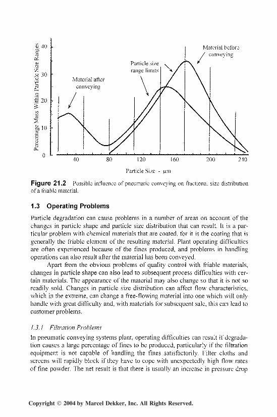
Figure 21.1 shows the influence on the cumulative particle size distributionfor the material before and after conveying. The mean particle size, based on the50% value, has changed from about 177 to 152 urn. The really significant effect,however, is shown in the fractional size distribution plot in Figure 21.2. In thismagnified plot the effect of degradation on the material can be clearly seen. Aconsiderable number of fines are produced and even on a percentage mass basisthese cause a significant secondary peak in the particle size distribution.
100
80
60
3 40
20
Material beforeconveying
Material afterconveying
40 80 120 160
Particle Size - urn
240
Figure 21.1 Possible influence of pneumatic conveying on cumulative particle sizedistribution of a friable material.
Copyright 2004 by Marcel Dekker, Inc. All Rights Reserved.
Particle Degradation 605
3 40oncC3
os§
c/5u 30
•S 20
a 10
Material beforeconveying
Particle size
Material afterconveying
40 80 120 160
Particle Size - u.m
200 240
Figure 21.2 Possible influence of pneumatic conveying on fractional size distributionof a friable material.
1.3 Operating Problems
Particle degradation can cause problems in a number of areas on account of thechanges in particle shape and particle size distribution that can result. It is a par-ticular problem with chemical materials that are coated, for it is the coating that isgenerally the friable element of the resulting material. Plant operating difficultiesare often experienced because of the fines produced, and problems in handlingoperations can also result after the material has been conveyed.
Apart from the obvious problems of quality control with friable materials,changes in particle shape can also lead to subsequent process difficulties with cer-tain materials. The appearance of the material may also change so that it is not soreadily sold. Changes in particle size distribution can affect flow characteristics,which in the extreme, can change a free-flowing material into one which will onlyhandle with great difficulty and, with materials for subsequent sale, this can lead tocustomer problems.
1.3.1 Filtration Problems
In pneumatic conveying systems plant, operating difficulties can result if degrada-tion causes a large percentage of fines to be produced, particularly if the filtrationequipment is not capable of handling the fines satisfactorily. Filter cloths andscreens wil l rapidly block if they have to cope with unexpectedly high flow ratesof fine powder. The net result is that there is usually an increase in pressure drop
Copyright 2004 by Marcel Dekker, Inc. All Rights Reserved.

606 Chapter 21
across the filter, and this could be a significant proportion of the total pressureavailable in a low pressure system.
This means that the pressure drop available for conveying the material willbe reduced, which in turn means that the mass flow rate of the material wi l l proba-bly have to be reduced in order to compensate. If this is not done there will be therisk of blocking the pipeline. Alternatively, if the filtration plant is correctly speci-fied, with material degradation taken into account, it is likely to cost very muchmore as a result. This, therefore, provides a direct financial incentive to ensure thatparticle degradation is minimized., even if it does not represent a problem withrespect to the material itself [2],
1.3.2 Flow Problems
In many systems there is a need to store the conveyed material in a hopper or silo.Flow functions can be determined for bulk particulate materials, from which hop-per wall angles and opening sizes can be evaluated, to ensure that the materialflows reliably at the rate required. A change in particle size distribution of a mate-rial, as a result of conveying operations, however, can result in a significantchange in flow properties. Thus a hopper designed for a material in the "as re-ceived" condition may be totally unsuitable for the material after it has been con-veyed. As a result it may be necessary to fit an expensive flow aid to the hopper torecover the situation.
1.3.3 Potential Explosion Problems
Many materials, in a dust cloud, can ignite and cause an explosion. Dust cloudsare clearly quite impossible to avoid somewhere in a pneumatic conveying system,and so this poses a problem with regard to the safe operation of such systems. Ofthose materials that are explosive, research has shown that it is only the fractionwith a particle size less than about 200 u.m that poses the problem. Degradationand attrition caused by pneumatic conveying, however, can result in the generationof a considerable number of fines, particularly if the material is friable. Even if thematerial did not represent a problem with respect to explosions in the "as re-ceived" condition, the situation could be very different after the material has beenconveyed.
1.4 Test Rigs and Data Sources
Little data is available on the degradation of materials in pneumatic conveyingsystems. This is partly due to the complexity of obtaining and analyzing the data,but mainly to the fact that so many variables are involved, together with the prob-lem of relating the data from one material and situation to another. A particularproblem with data obtained from a pneumatic conveying system pipeline is that itis very difficult to separate the individual contributions made by the bends and thestraight pipeline.
Copyright 2004 by Marcel Dekker, Inc. All Rights Reserved.
Particle Degradation 607
A further problem is that in a pipeline there is a gradual expansion of theconveying air, which means that the particle velocity is constantly changing. Ve-locity is a major variable in particle degradation and so this makes attempts at de-vising experimental plans and analysis of results very difficult.
The major source of information is probably from the basic research that hasbeen undertaken with small bench scale test rigs in which particles have been im-pacted against test materials under controlled conditions. This work has often beencarried out to assist in an understanding of erosive wear problems. Although muchof this work cannot be related directly to pneumatic conveying situations, it canprovide valuable information of a comparative nature on a number of variables inthe process.
1.4.1 Acceleration Tube Device
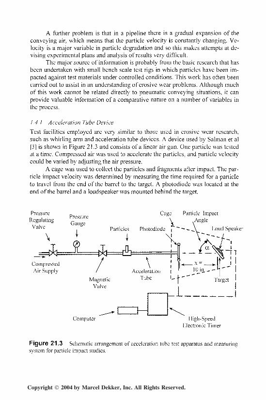
Test facilities employed are very similar to those used in erosive wear research,such as whirling arm and acceleration tube devices. A device used by Salman et al[3] is shown in Figure 21.3 and consists of a linear air gun. One particle was testedat a time. Compressed air was used to accelerate the particles, and particle velocitycould be varied by adjusting the air pressure.
A cage was used to collect the particles and fragments after impact. The par-ticle impact velocity was determined by measuring the time required for a particleto travel from the end of the barrel to the target. A photodiode was located at theend of the barrel and a loudspeaker was mounted behind the target.
PressureRegulating
Valve
Cage
\
CompressedAir Supply
Particle Impact.Angle
Speaker
Computer High-SpeedElectronic Timer
Figure 21.3 Schematic arrangement of acceleration tube test apparatus and measuringsystem for particle impact studies.
Copyright 2004 by Marcel Dekker, Inc. All Rights Reserved.

608 Chapter 21
In order to study the particle degradation process, brittle materials were usedto ensure that no plastic deformation should take place. Three types of particlewere used and tested. These were aluminum oxide, polystyrene and glass, and allthe particles were spherical. The majority of the work was carried out with 0-2 indiameter aluminum oxide particles, with particle velocities up to about 6000ft/min. For every test, 100 particles were impacted, and the number of unbrokenparticles was counted to provide an assessment of the degradation.
2 INFLUENCE OF VARIABLES
The variables in particle degradation are similar to those associated with erosivewear. Velocity, once again, is probably the most important, but particle size andconcentration also play a part. Particle impact angle is equally important, and has amajor influence with respect to the selection of pipeline bend geometry. The influ-ence of both particle materials and surface materials must also be given due con-sideration. As with erosive wear, much of the research work into the subject hasbeen carried out for various other purposes, and so the range of parameters inves-tigated is often beyond those associated with pneumatic conveying, but it doesprovide useful information on the general trends of the variables.
2.1 Velocity
The relative velocity between particles and surfaces has a major influence on thenature and extent of the degradation and is probably the most important variable inthe problem. In any collision the kinetic energy of the particles has to be absorbedand may provide sufficient energy for fracture. If the collision is elastic, with ahigh coefficient of restitution, much of the kinetic energy will reappear as particlevelocity. In plastic collisions much of the kinetic energy will be converted to heat.
Low velocity impacts tend to knock small chips from the edges of particles,whereas high velocity collisions are more likely to shatter particles. In general therate of damage has been found to be a power law function of velocity, in much thesame way as the erosive wear process. The range in value of the power coefficientis also large, and can vary between one and five, depending upon the conveyedmaterial and the system being considered. The possibility of there being a thresh-old value of velocity, below which no degradation occurs, is also a possibility.
2. /. / Peas
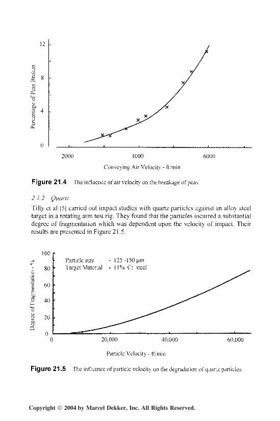
Agricultural products have been widely used in test work. Segler [4] investigatedthe effects of air velocity, moisture content, pipeline diameter and material con-centration on the damage of peas, as a result of pneumatic conveying. His test loopwas 240 ft long, 4'/2 in bore and contained 4 bends. The results of his tests on theeffect of aii- velocity are presented in Figure 21.4. These showed that the damageincreased approximately with the cube of air velocity.
Copyright 2004 by Marcel Dekker, Inc. All Rights Reserved.
Particle Degradation 609
12
IX^Ho
S 4
2000 4000
Conveying Air Velocity - ft/min
6000
Figure 21.4 The influence of air velocity on the breakage of peas.
2.7.2 Quartz
Tilly et al [5] carried out impact studies with quartz particles against an alloy steeltarget in a rotating arm test rig. They found that the particles incurred a substantialdegree of fragmentation which was dependent upon the velocity of impact. Theirresults are presented in Figure 21.5.
I
Particle size - 125-150 urnTaraet Material - 11% Cr steel
100
80
60
40i-M
I 20g?o
00 20,000 40,000 60,000
Particle Velocity - ft/min
Figure 21.5 The influence of particle velocity on the degradation of quartz particles.
Copyright 2004 by Marcel Dekker, Inc. All Rights Reserved.

610 Chapter 21
The velocity range comes as a result of their work being applied to aircraftengines. From this it would appear that for fragmentation to occur it is necessaryto exceed a threshold value of velocity. Below this velocity the particles may beconsidered to behave elastically. From Figure 21.5 this would appear to occur at avelocity of about 3000 ft/min for this material.
In work by Tilly and Sage [6] they impacted quartz particles in the sizerange of 100 to 225 urn at velocities of 12,000, 26,000 and 60,000 ft/min. Theirresults, in terms of particle size distribution, are presented in Figure 21.6. Al-though this data is for conveying velocities very much higher than those thatwould be encountered in a pneumatic conveying system, they relate to a singleimpact and so help to illustrate the nature of the problem, for many materials thatare conveyed are significantly more friable than quartz.
2.7.3 A lum inum Oxide
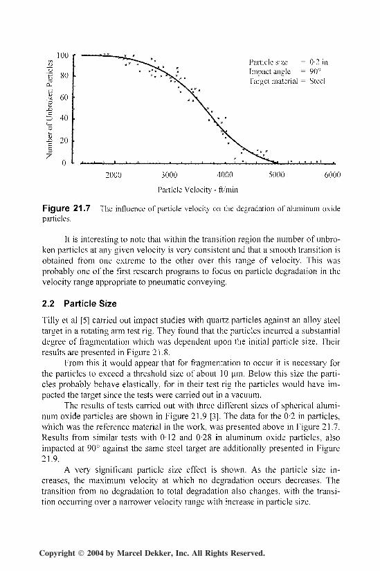
The results of a program of tests carried out with 0-2 inch aluminum oxide parti-cles impacted at 90° against a steel target are presented in Figure 21.7 [3"|. In thisplot the experimental data has been included to show how the relationship wasderived and to show the limits of scatter in the results. The relationship is typicalof the results obtained and so where families of curves are presented in subsequentfigures from this program of work, experimental data has been omitted for clarity.
It will be seen from Figure 21.7 that there is a very rapid transition in parti-cle velocity from zero breakage to total degradation. Below a particle velocity ofabout 1800 ft/min only elastic deformation occurs and there is no particle degrada-tion. Above a particle velocity of about 5000 ft/min, however, the stress inducedby the impact is always sufficient to damage every particle.
100
80
60
40
20
Particle Velocity- ft/min
BeforeImpact
Particles - QuartzTarget - 11% Cr Steel
50 100
Mean Particle size
150 200
Figure 21.6 Influence of particle velocity on size distribution generated with quartz.
Copyright 2004 by Marcel Dekker, Inc. All Rights Reserved.
Particle Degradation 611
100
80
60
CD 40
X 20
Particle size = 0-2 inImpact angle = 90°Target material = Steel
2000 3000 4000
Particle Velocity - ft'min
5000 6000
Figure 21.7 The influence of particle velocity on the degradation of aluminum oxideparticles.
It is interesting to note that within the transition region the number of unbro-ken particles at any given velocity is very consistent and that a smooth transition isobtained from one extreme to the other over this range of velocity. This wasprobably one of the first research programs to focus on particle degradation in thevelocity range appropriate to pneumatic conveying.
2.2 Particle Size
Tilly et al [5] carried out impact studies with quartz particles against an alloy steeltarget in a rotating arm test rig. They found that the particles incurred a substantialdegree of fragmentation which was dependent upon the initial particle size. Theirresults are presented in Figure 21.8.
From this it would appear that for fragmentation to occur it is necessary forthe particles to exceed a threshold size of about 10 urn. Below this size the parti-cles probably behave elastically, for in their test rig the particles would have im-pacted the target since the tests were carried out in a vacuum.
The results of tests carried out with three different sizes of spherical alumi-num oxide particles are shown in Figure 21.9 [3], The data for the 0-2 in particles,which was the reference material in the work, was presented above in Figure 21.7.Results from similar tests with 0-12 and 0-28 in aluminum oxide particles, alsoimpacted at 90° against the same steel target are additionally presented in Figure21.9.
A very significant particle size effect is shown. As the particle size in-creases, the maximum velocity at which no degradation occurs decreases. Thetransition from no degradation to total degradation also changes, with the transi-tion occurring over a narrower velocity range with increase in particle size.
Copyright 2004 by Marcel Dekker, Inc. All Rights Reserved.

612 Chapter 21
100
80
60S01)S
40
ob 20
Particle Velocity - 60,000 ft/minTarget Material - 11% Cr Steel
50 100 150
Initial Mean Particle size - u.m
200
Figure 21.8 The influence of initial particle size on the degradation of quartz particles.
2.2.7 Particle Velocity Influence
In more recent work on the influence of particle size, fertilizer particles, also hav-ing particle diameters of 0-12, 0-20 and 0-28 in, were pneumatically conveyed in atest facility to assess their degradation [7]. In this case the velocity used was that ofthe conveying air and not that of the particles. In terms of air velocity the 0-12 inparticles degraded the most and the 0-28 in particles the least.
100
0-
g 60^XJc
o!-~O
X)
40
20
Impact Angle-90°
Target Material- Steel
0-12
1000 2000 3000 4000
Particle Velocity - ft / min
5000
Figure 21.9 The influence of particle velocity and particle size on the degradation ofaluminum oxide particles.
Copyright 2004 by Marcel Dekker, Inc. All Rights Reserved.

Particle Degradation 613
The reason for this is that when it is the air velocity that is held constant, thesmaller particles are accelerated to a higher velocity than the larger particles, asillustrated earlier with Figure 15.10. It is because particle velocity has a greaterinfluence on degradation than particle size that a reversal in the influence of parti-cle size has occurred.
2.3 Surface Material
With erosive wear of surface materials it has been found that the resilience of thesurface material can have a significant influence on erosive wear, and that rubbersand polymers can offer better wear resistance than metals having a very highhardness value in certain cases. Since the mechanisms of erosion and degradationhave many similarities, it is quite possible that resilient materials could offer verygood resistance to particle degradation.
2.3.1 Material Type
Further work by Tilly and Sage [6] showed that fragmentation is also dependentupon the type of target material. Figure 21.10 shows a comparison of their resultsfor quartz impacted against nylon and fiberglass, which with their earlier resultsfor alloy steel demonstrates the complex nature of the problem. Degradation interms of the influence of initial particle size is used for the comparison in this case.
The results of tests carried out on four different target materials are pre-sented in Figure 21.11 [3]. In each case the targets were 0-2 in thick and they wereimpacted by 0-2 in diameter aluminum oxide particles at an angle of 90°.
100xoo-
c 80
I 60
5hcd
'•o 40<L>
aQ 20
0
Target Material
Impact Angle - 90°
Particle,Velocity/
Steel - 60,000 ft/min
Fiberglass - 50,000 ft/min
50 100 150
Initial Mean Particle size -
200 250
Figure 21.10 The influence of initial particle size and target material on the degrada-tion of quartz particles.
Copyright 2004 by Marcel Dekker, Inc. All Rights Reserved.

614 Chapter 21
100r •*—- •"•— —"•= — Plexiglass
80L ^ ^ . . .Aluminum
60
5 40<+-<o
I 20
J:
Particle Size - 0-2 inInroad Angle - 90°
1000 2000 3000 4000 5000
Particle Velocity - ft/min
Figure 21.11 The influence of particle velocity and target material on the degradationof aluminum oxide particles.
This also shows very clearly that target material can have a very marked ef-fect on degradation. Although there is little difference in the maximum value ofparticle velocity at which no degradation occurs, varying from 2000 ft/min forsteel to about 3000 ft/min for Plexiglas and aluminum, very significant differencesexist in the transition region between no degradation and total degradation. In thecase of the steel and glass targets the transition is very rapid. For the aluminumand Plexiglas, however, the transition is very slow, and so a high velocity impactagainst these materials would only result in limited damage occurring.
2.5.2 Surface Thickness
A similar program to that reported in relation to Figure 21.11 was carried out withsteel targets of varying thickness [7]. If the conveyed material is not abrasive, inaddition, a thin walled surface would also help reduce degradation, for the workshowed a significant reduction in degradation of the particles with an 0-04 in thicktarget as compared with an 0'08 in thick target.
The force acting on a particle is equal to its mass times the rate of decelera-tion. This force must be reduced in order to reduce the damage to particles on im-pact against a surface. This can be achieved to a certain extent by using either aresilient surface material or a surface material that wi l l flex on impact.
2.4 Particulate Material
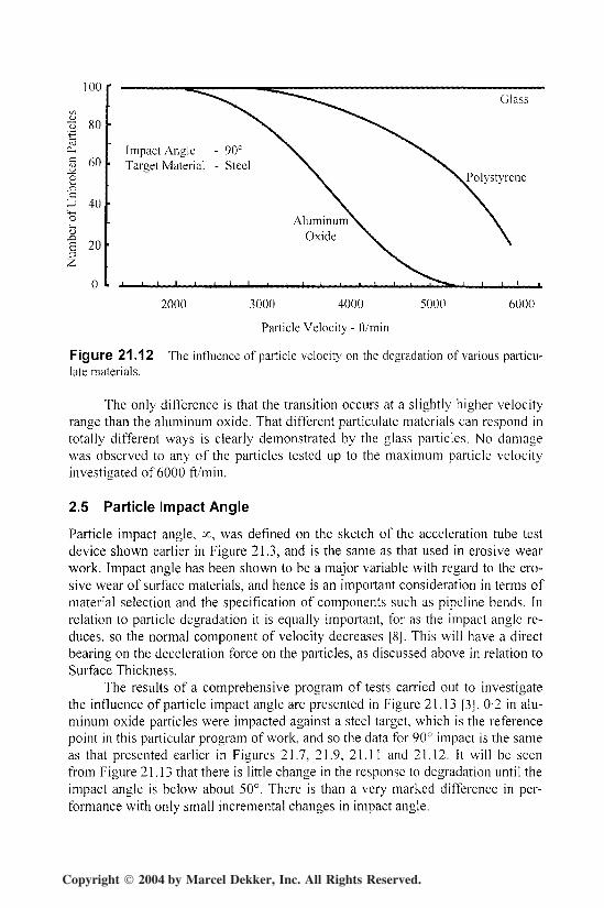
In Figure 21.12 the data for the aluminum oxide of Salman et al [3J is presentedagain, together with the results from identical tests carried out with polystyreneand glass particles. It will be seen from this that polystyrene particles suffer a simi-lar transition from zero breakage to total degradation.
Copyright 2004 by Marcel Dekker, Inc. All Rights Reserved.
Particle Degradation 615
100
Impact Angle - 90°Target Material - Steel5 60
o
1 20
40Aluminum11
Oxide
2000 3000 4000 5000 6000
Particle Velocity - ft/min
Figure 21.12 The influence of particle velocity on the degradation of various particu-late materials.
The only difference is that the transition occurs at a slightly higher velocityrange than the aluminum oxide. That different particulate materials can respond intotally different ways is clearly demonstrated by the glass particles. No damagewas observed to any of the particles tested up to the maximum particle velocityinvestigated of 6000 ft/min.
2.5 Particle Impact Angle
Particle impact angle, oc, was defined on the sketch of the acceleration tube testdevice shown earlier in Figure 21.3, and is the same as that used in erosive wearwork. Impact angle has been shown to be a major variable with regard to the ero-sive wear of surface materials, and hence is an important consideration in terms ofmaterial selection and the specification of components such as pipeline bends. Inrelation to particle degradation it is equally important, for as the impact angle re-duces, so the normal component of velocity decreases [8]. This will have a directbearing on the deceleration force on the particles, as discussed above in relation toSurface Thickness.
The results of a comprehensive program of tests carried out to investigatethe influence of particle impact angle are presented in Figure 21.13 [3]. 0-2 in alu-minum oxide particles were impacted against a steel target, which is the referencepoint in this particular program of work, and so the data for 90° impact is the sameas that presented earlier in Figures 21.7, 21.9, 2 1 . 1 1 and 21.12. It wi l l be seenfrom Figure 21.13 that there is little change in the response to degradation unti l theimpact angle is below about 50°. There is than a very marked difference in per-formance with only small incremental changes in impact angle.
Copyright 2004 by Marcel Dekker, Inc. All Rights Reserved.

616 Chapter 21
100t/D
—
'4 80C3n_
jj 60o
| 40'o« 20£
Particle Size - 0-2 inTarget Material - Steel
2000 3000 4000 5000
Particle Velocity - ft/min
6000
Figure 21.13 The influence of particle velocity and impact angle on the degradation ofaluminum oxide particles
With a decrease in particle impact angle it would appear that there is littlechange in the particle velocity at which the onset of degradation occurs. The tran-sition from zero degradation to total degradation, however, becomes an increas-ingly more gradual process as the particle impact angle reduces. At impact anglesof 15° and 20° it would appear that this transitional process will be spread over avery wide range of velocity values. At an impact angle of 10°, however, there is asignificant change once again, in that no particle degradation was recorded at allup to 6000 ft/min. In Figure 21.14 an alternative plot of the data from this programof tests is presented.
Particle size - 0-2 inParticle velocity - 4600 ft/minTarget material - Steel
10 20 30 40 50 60Particle Impact Angle - a - degrees
80 90
Figure 21.14 The influence of particle impact angle on the degradation of aluminumoxide particles.
Copyright 2004 by Marcel Dekker, Inc. All Rights Reserved.
Particle Degradation 617
This is effectively a slice taken from Figure 21.13 at a particle velocity of4600 ft/min. It will be seen from this that tests were carried out at regular incre-ments of impact angle of about 10° between 10° and 90°. This plot shows quiteclearly that at impact angles below about 12° no degradation occurs, and that atimpact angles above about 55° the degradation remains essentially constant at themaximum value for this particular impact velocity.
2.6 Other Variables
Segler [4] investigated the influence of moisture content on particle degradationand showed that degradation can increase dramatically with decrease in moisturecontent. The results of the following three tests with peas show the sensitivity tothis variable:
Moisture Content-% 17-1 16-1 15-4Broken Particles -% 0-1 1-1 1 1 - 1
Segler investigated the effect of particle concentration and found that thedamage decreased as the solids loading increased. The damage produced when thepeas were introduced individually was four times higher than in dense flow. Asimilar effect is found in erosive wear and can be attributed to the cushioning ef-fect of dense flows.
He also examined the damage to the peas in identical pipelines havingnominal bores of 2 and 10 inch. It was found that the damage in the 2 in bore pipe-line was two to three times greater than that in the 10 in bore pipeline. His expla-nation was that the frequency of pipe wall impacts, for such large particles, wouldbe more frequent for the small bore pipeline.
3 RECOMMENDATIONS AND PRACTICAL ISSUES
The results from the various programs of work reported here have produced somevery interesting relationships with respect to many of the variables investigated,and should provide useful guidance to the design engineer who has to ensure thatmaterial degradation is reduced to a minimum in pneumatic conveying systempipelines.
3.1 Particle Velocity
Particle velocity has been a major consideration in this work and it has beenshown quite clearly that there is a threshold value of particle velocity below whichno degradation occurs. The value of this particle velocity for the aluminum oxidewas about 2000 ft/min and was influenced only slightly by particle size, targetmaterial, and particle impact angle above about 15°.
Copyright 2004 by Marcel Dekker, Inc. All Rights Reserved.
618 Chapter 21
3.1.1 Dense Phase Conveying
At velocities only slightly lower than this, however, the mode of conveyingchanges from dilute phase, suspension flow, to dense phase, non-suspension flow,for many of those materials capable of being conveyed in dense phase. In densephase conveying little impact occurs in horizontal pipelines and the mode of con-veying mostly involves sliding of the particles through the pipeline. With materialshaving good permeability, conveying is in plugs and slugs, and for materials hav-ing good air retention, it is as a moving bed along the bottom of the pipeline.
When particles slide through the pipeline the interaction results in attritionrather than degradation. In dilute phase there may be little particle to pipe wallinteraction, and it is suspected that most of the damage results from impact withpipeline bends. In dense phase, although the velocity is low, there is a significantamount of particle to pipe wall interaction and for certain materials this is likely tocause more damage to the particles than the bends.
As a consequence it is possible for some materials to suffer a greater amountof damage in low velocity dense phase flow than they would in higher velocitydilute phase flow. It is important, therefore, to examine the relative effects of deg-radation and attrition on the conveyed material before deciding upon the type ofpneumatic conveying system to be employed.
3.1.2 Dilute Phase Conveying
For many materials dense phase conveying is not an option, for the majority ofmaterials can not be conveyed at low velocity in a conventional conveying system.For these materials conveying has to be in suspension flow and so if the material isfriable, degradation must be limited. To this end the material should be conveyedat as low a velocity as possible, consistent with reliable conveying, and the pipe-line should be stepped to a larger bore part way along its length to reduce the highconveying air velocities that result at the end of the pipeline.
With a 15 lbf/in2 pressure drop in a positive pressure system, discharging toatmospheric pressure, the conveying air velocity wil l approximately double fromthe material feed point to discharge. For the situation presented in Figure 21.7 itwi l l be seen that at 2000 ft/min no damage occurs, but at 4000 ft/min 80% of theparticles are broken.
As the air expands through the pipeline, therefore, it is the bends at the endof the pipeline, in a single bore line, that are likely to cause the majority of thedamage. By stepping the pipeline the maximum velocity in the pipeline could pos-sibly be limited to 3000 or 3200 ft/min, at which the degradation would be limitedto only 30%.
3.2 Particle Impact Angle
For given conveying conditions, particle impact angle is probably the most impor-tant variable with respect to pneumatic conveying system pipelines. The angle ofimpact of particles against pipeline walls will generally be very low since particles
Copyright 2004 by Marcel Dekker, Inc. All Rights Reserved.
Particle Degradation 619
will only suffer a glancing impact. From the data presented here it would appearthat little degradation will occur in straight pipeline, even for long pipelines andrepeated impacts.
It is clearly major changes in flow direction, and in particular bends, that arelikely to result in the majority of degradation occurring. In this respect, particleimpact angle can be related approximately to the radius of curvature of a bend. Ina short radius bend the particles will impact at a high value of angle, but in a longradius bend the impact angle will be much lower, as illustrated in the previouschapter with Figure 20.14. Since degradation reduces significantly with reductionin impact angle, the use of long radius bends would be recommended in any sys-tem where particle degradation needs to be minimized.
3.3 Bend Material
The choice of material for the pipeline, and in particular the bends, provides an-other means by which particle degradation can be minimized. Although there islittle change in the value of the lower threshold velocity, below which no degrada-tion occurs, with respect to target material, there is a very significant effect on theupper threshold value.
Thus, for a given particle impact velocity, very much less damage wil l resultto particles if they impact against a surface such as Plexiglas or aluminum, thanwill occur if they impact against steel or glass. If it is possible to use a more resil-ient material, such as rubber or polyurethane, an even more significant reductionin particle degradation may be achieved.
4 PNEUMATIC CONVEYING DATA
To provide some data on the potential order of magnitude of the problem of deg-radation, for materials conveyed in dilute phase suspension flow in a pneumaticconveying system, four different materials were pneumatically conveyed and theresulting degradation was monitored. A large scale pneumatic conveying facilitywas used and on-line samples were taken for analysis. Each material was re-circulated through the test loop a number of times so that the influence of convey-ing distance could also be investigated [9],
4.1 Material Degradation Data
The data has, in fact, been presented earlier, in the chapters dealing with convey-ing data on specific materials. Thus data on coal will be found in Chapter 10 atsection 5 and with Figure 10.28. Data on both sodium chloride (common salt) andsodium carbonate (soda ash) were included in Chapter 11 around Figures 11.5 to11.7. The fourth material was silica sand and this was included in Chapter 14 withFigures 14.6 and 14.7.
Copyright 2004 by Marcel Dekker, Inc. All Rights Reserved.

620 Chapter 21
4.2 Conveying Characteristics
The influence that pneumatic conveying can have on the conveying characteristicsof a material has been considered for many different materials. As a result of re-circulating materials, in order to derive conveying characteristics, some of themore friable materials have degraded to such an extent that the conveying charac-teristics for the material have changed significantly. It must be recognized that thepneumatic conveying of a friable material can also change the conveying charac-teristics of a material.
5 PARTICLE MELTING
Particle melting is a form of material degradation that often occurs in pneumaticconveying plant handling plastic type materials, particularly in pelletized form. Ifconventional pipeline is used, materials such as polyethylene, nylon and polyesterscan form cobweb-like agglomerates. They are variously given names such as 'an-gel hairs', 'raffia', 'snake skins' and 'streamers'.
They frequently cause blockages at line diverters and filters which requireplant interruption to remove them. Equipment is generally installed at the termi-nating end of the system for this purpose. Such equipment is necessary becausethey also cause material rejection by customers, for the presence of these contami-nants in the product is undesirable.
5.1 Mechanics of the Process
The streamers are caused by the pellets impacting against the bends and pipewalls. A considerable amount of energy is converted into heat by the friction of thetwo surfaces when they touch. If the surface of the pipe is smooth, the pellet willslide. This contact, though momentary, decelerates the particle by friction which istransformed into heat. This is generally sufficient to raise the temperature at thesurface of the pellet to its melting point. To a certain extent this is analogous to thethermal model proposed for erosive wear.
5.2 Influence of Variables
The onset of the formation of these angel hairs or streamers is the result of a com-bination of conditions. Particle velocity is the most important, but it also dependsupon the temperature of both the pipe and the pellets, and the solids loading ratioof the conveyed material.
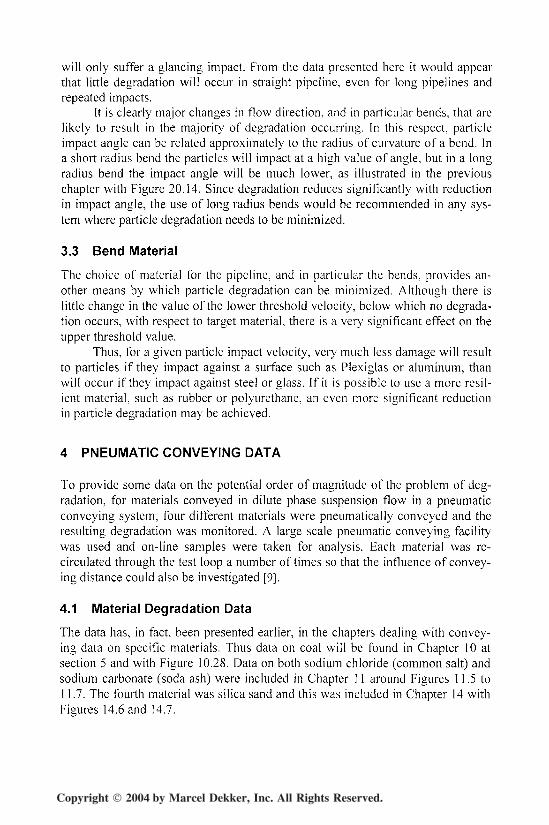
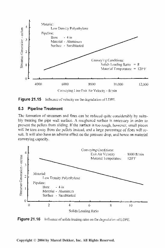
The influence of conveying line exit air velocity for low density polyethyl-ene is shown in Figure 21.15 and the influence of solids loading ratio for this samematerial is given in Figure 21.16 [10]. In each case the degradation of the materialis expressed in terms of the mass of streamers and fines produced, in ounces, perton of low density polyethylene conveyed.
Copyright 2004 by Marcel Dekker, Inc. All Rights Reserved.
Particle Degradation 621
O
0
Material:Low Density Polyethylene
Pipeline:Bore - 4 inMaterial - AluminumSurface - Sandblasted
Conveying Conditions:Solids Loading Ratio = 8Material Temperature = 120°F
4000 12,0006000 8000 10,000
Conveying Line Exit Air Velocity - ft/min
Figure 21.15 Influence of velocity on the degradation of LDPE.
5.3 Pipeline Treatment
The formation of streamers and fines can be reduced quite considerably by suita-bly treating the pipe wall surface. A roughened surface is necessary in order toprevent the pellets from sliding. If the surface is too rough, however, small pieceswill be torn away from the pellets instead, and a large percentage of fines will re-sult. It will also have an adverse effect on the pressure drop, and hence on materialconveying capacity.
Conveying Conditions:Exit Air Velocity = 8000 fl/minMaterial Temperature = 120°Fo
o
O
Material:Low Density Polyethylene
Pipeline:Bore - 4 inMaterial - AluminumSurface - Sandblasted
4 6
Solids Loading Ratio
10
Figure 21.16 Influence of solids loading ratio on the degradation of LDPE.
Copyright 2004 by Marcel Dekker, Inc. All Rights Reserved.

622 Chapter 21
Although the results presented in Figures 21.15 and 16 were obtained fromtests carried out with pipe surfaces roughened by sand blasting, this treatment isnot recommended as it will result in the generation of a large percentage of fines.Also, this roughness is relatively shallow in depth and an aluminum surface willwear so that the pipe must be retreated in six to twelve months [10].
REFERENCES
1. D. Mills and J.S. Mason. Problems of particle degradation in pneumatic conveyingsystems. Proc Pneumotransport 4. Paper F3. 10 pp. BHRA Conf. Carmel, California.June 1978.
2. D. Mills and J.S. Mason. The effect of pipe bends and conveying length upon particledegradation in pneumatic conveying systems. Proc 3rd Powder and Bulk Solids Conf.Chicago. May 1978.
3. A.D. Salman, M. Szabo, I. Angyal, A. Verba, and D. Mills. The design of pneumaticconveying systems to minimize product degradation. Proc 13th Powder and Bulk Sol-ids Conf. Chicago. May 1988.
4. G. Segler. Pneumatic grain conveying with special reference to agricultural applica-tions. Germany. 1951.
5. G.P. Tilly. Erosion caused by solid particles. Treatise on Materials Science and Tech-nology. Vol 13, pp 287-319. Academic Press Inc. 1979.
6. G.P. Tilly and W. Sage. The interaction of particle and material behavior in erosionprocesses. Wear, Vol 16, pp 447-465. 1970.
7. A.D. Salman, A. Verba, and D. Mills. Particle degradation in dilute phase pneumaticconveying systems. Proc 17th Powder and Bulk Solids Conf. Chicago. May 1992.
8. D. Mills. Particle degradation in pneumatic conveying, pp 31-48. Freight Pipelines. EdG.F. Round. Elsevier. 1993.
9. D. Mills. The degradation of bulk solids by pneumatic conveying and its simulationby small scale rigs. BMHB report. Feb 1988.
10. J. Paulson. Effective means for reducing formation of fines and streamers. Proc Confon Polyolefins. Soc of Plastic Engineers. Houston. 1978.
Copyright 2004 by Marcel Dekker, Inc. All Rights Reserved.