matchmover® pro 3 - comp.nus.edu.sg
TRANSCRIPT

User Guide

Legal notice
Copyright © 2004 REALVIZ S.A. All rights reserved.Information in this document is subject to change without notice. The software described in this document is furnished under a license agreement or nondisclosure agreement. The software may be used or copied only in accordance with the terms of those agreements. No part of this publication may be reproduced, stored in a retrieval system, or transmitted in any form or any means electronic or mechanical, including photocopying and recording for any purpose other than the purchaser's personal use without the written permission of REALVIZ S.A. Product information and specifications are subject to change without notice. This publication may include inadvertent technical inaccuracies or typographical errors. REALVIZ provides this information “as is”, without warranty of any kind, either expressed or implied, including any implied warranties of merchantability or fitness for a particular purpose.All photos © REALVIZ S.A.REALVIZ S.A.Arep Center1 traverse des BrucsSOPHIA ANTIPOLIS06560 VALBONNEFRANCEwww.realviz.com
Trademarks
MatchMover is a registered trademark of REALVIZ S.A. in France, the USA, and other countries. Microsoft and Windows are registered trademarks of Microsoft Corporation. Intel and Pentium are registered trademarks of Intel Corporation. Macintosh is a registered trademark of Apple Computer, Inc. This product includes software developed by the Apache Software Foundation (http.//www.apache.org). Other brands and their products are trademarks or registered trademarks of their respective holders and should be noted as such.Document Reference. MMP30-U1-MWL-1March 7, 2004

Other REALVIZ® Products
For other REALVIZ® products, visit our website www.realviz.com/products.
REALVIZ® Stitcher®
REALVIZ® Stitcher® is the way to build high-quality panoramas for the Web, film, print, and 3D. With advanced features REALVIZ® Stitcher® gives photographers and artists the power to deliver the most impressive panoramas in the formats they need. REAVIZ Stitcher® combines overlapping photos easily into stunning wide-angle, high-quality images for creating high-impact Web pages, definition mattes, environment maps, image sequences, and 3D models.
REALVIZ® ImageModeler®
REALVIZ® ImageModeler® is the way to create 3D models using photographs. Using advanced algorithms, REALVIZ® ImageModeler® extracts 3D information and constructs highly accurate 3D models. These models are textured from the original images for photo-real results and can then be exported to your favorite authoring package. Additional features such as the ability to make point-to-point measurements and to create a single texture per object with its Unwrap Texture feature help you create models that suit your individual needs.
REALVIZ® Scenewe@ver®
REALVIZ® SceneWe@ver® is the way to integrate 3D objects into pictures or panoramic images. By combining the beauty of photos with the interactivity of Web 3D, this innovative software brings a whole new dimension to your multimedia projects. REALVIZ® SceneWe@ver® creates true 3D environments from stills or panoramic photos, imports 3D objects, positions them, and creates object hierarchies for delivery to Macromedia® Director®/Shockwave® and interactive Web formats. REALVIZ® SceneWe@ver® provides leading-edge content creators and multimedia artists with rapid, easy, and attractive 2D/3D authoring capabilities, particularly suited for architectural and Web-interactive projects.
REALVIZ® ReTimer®
REALVIZ® ReTimer® is the way to control time for astonishing slow motion or fast motion effects. REALVIZ® ReTimer® lets you speed up or slow down any video, film, or image sequence, giving you the ultimate flexibility during post-production. With an innovative technology that enables calculation of each pixel move, REALVIZ® ReTimer® automatically generates new frames in between existing frames, enabling high quality slow downs.


Contents
MatchMover® Pro 3User Guide
v
Chapter 1 Introduction 11.1. Introducing MatchMover® Pro 3...................................................................................................... 31.2. What’s new in MatchMover® Pro 3? ................................................................................................ 3
1.2.1. Major improvements ............................................................................................................... 31.2.2. Additional features................................................................................................................... 4
1.3. About this guide .................................................................................................................................. 51.3.1. Type conventions .................................................................................................................... 5
1.4. Getting help ......................................................................................................................................... 51.4.1. Tutorials .................................................................................................................................... 51.4.2. Online Help .............................................................................................................................. 51.4.3. Tech Center .............................................................................................................................. 61.4.4. Technical Support.................................................................................................................... 6
1.5. Installation............................................................................................................................................ 61.5.1. Minimum system requirements ............................................................................................. 61.5.2. Uninstalling previous versions............................................................................................... 61.5.3. Licensing ................................................................................................................................... 7
1.5.3.1. Node-locked licenses ............................................................................................... 71.5.3.2. Floating licenses........................................................................................................ 7
Chapter 2 Overview 92.1. About matchmoving......................................................................................................................... 112.2. About footage.................................................................................................................................... 11
2.2.1. About helper images.............................................................................................................. 112.2.1.1. Using helper images with images taken with a tripod camera......................... 122.2.1.2. Using helper images with images taken with a travelling camera ................... 12
2.2.2. About frame rate.................................................................................................................... 132.3. About cameras................................................................................................................................... 13
2.3.1. About camera parameters..................................................................................................... 142.3.1.1. Pixel aspect ratio..................................................................................................... 142.3.1.2. Non-linear distortion ............................................................................................. 14
2.4. About point tracks ............................................................................................................................ 152.4.1. About automatic 2D tracking .............................................................................................. 152.4.2. About supervised tracking.................................................................................................... 15
2.5. About mattes ..................................................................................................................................... 162.6. About 3D objects.............................................................................................................................. 162.7. About camera computation............................................................................................................. 16
Contentsvi
2.7.1. About keyframes.................................................................................................................... 172.7.2. About relations on 3D points.............................................................................................. 172.7.3. About survey points .............................................................................................................. 172.7.4. About camera constraints..................................................................................................... 172.7.5. About motion control........................................................................................................... 17
Chapter 3 Tutorials 193.1. Basic tutorial ...................................................................................................................................... 21
3.1.1. Load the footage.................................................................................................................... 213.1.2. Run the automatic tracker .................................................................................................... 233.1.3. Check the results.................................................................................................................... 24
3.2. Supervised tracking tutorial ............................................................................................................. 263.2.1. Load the footage.................................................................................................................... 273.2.2. Create manual tracks ............................................................................................................. 273.2.3. Supervised tracking ............................................................................................................... 323.2.4. Calibrate the cameras ............................................................................................................ 323.2.5. Create a coordinate system .................................................................................................. 323.2.6. Add a 3D object..................................................................................................................... 33
3.3. Object-based tracking with elastics tutorial .................................................................................. 343.3.1. Load the footage.................................................................................................................... 353.3.2. Import the 3D mesh ............................................................................................................. 353.3.3. Set up the trackers and the survey points .......................................................................... 363.3.4. Solve and check the results .................................................................................................. 38
Chapter 4 Interface Guide 394.1. Interface overview ............................................................................................................................ 414.2. The Toolbars ..................................................................................................................................... 424.3. The Workspace ................................................................................................................................. 43
4.3.1. Switching between the 2D and 3D mode.......................................................................... 434.3.2. Changing the viewport layout.............................................................................................. 444.3.3. Resizing viewports................................................................................................................. 44
4.4. Working in2D mode......................................................................................................................... 444.4.1. Displaying the 2D View attributes...................................................................................... 454.4.2. Changing the time in the 2D View ..................................................................................... 464.4.3. Freezing the time ................................................................................................................... 464.4.4. Resetting the current view.................................................................................................... 474.4.5. Navigating in the 2D View................................................................................................... 47
MatchMover® Pro 3User Guide
vii
4.5. Working in 3D Mode ....................................................................................................................... 484.5.1. Displaying the 3D View attributes ...................................................................................... 494.5.2. Changing the number of wireframe divisions ................................................................... 494.5.3. Changing the size of the 3D Helpers ................................................................................. 504.5.4. Changing the Grid Step ........................................................................................................ 504.5.5. Lock on Camera mode.......................................................................................................... 504.5.6. Navigating in the 3D View................................................................................................... 51
4.6. Browsing the footage........................................................................................................................ 514.6.1. Selecting a Play Mode............................................................................................................ 52
4.7. Project Window................................................................................................................................. 524.7.1. Project Window folders ........................................................................................................ 53
4.8. Track Window................................................................................................................................... 544.8.1. The Track View...................................................................................................................... 54
4.8.1.1. Navigation in the Track View .............................................................................. 554.8.1.2. Track View folders ................................................................................................. 55
4.8.2. The Graph Editor.................................................................................................................. 564.8.3. The Track Status View.......................................................................................................... 56
4.9. Parameters Window.......................................................................................................................... 564.10. Actions Stack Window................................................................................................................... 574.11. Time Line Window......................................................................................................................... 57
4.11.1. Changing the current time using the Slider ..................................................................... 584.11.1.1. Changing the current frame using the Numeric Field.................................... 58
4.11.2. Defining a Work Area......................................................................................................... 584.11.3. Resetting the Work Area .................................................................................................... 59
4.12. Magnifier Window......................................................................................................................... 594.13. Keyboard shortcuts ........................................................................................................................ 61
4.13.1. Default keyboard shortcuts................................................................................................ 61
Chapter 5 User Guide 635.1. Managing projects ............................................................................................................................. 65
5.1.1. Setting the project preferences ............................................................................................ 655.1.1.1. Setting the image cache size.................................................................................. 665.1.1.2. Flushing the cache.................................................................................................. 665.1.1.3. Resetting the project preferences......................................................................... 66
5.1.2. Setting user-defined shortcuts ............................................................................................. 665.2. Managing footage.............................................................................................................................. 66
5.2.1. Importing footage.................................................................................................................. 665.2.1.1. Loading a sequence ................................................................................................ 675.2.1.2. File mask naming convention............................................................................... 685.2.1.3. Loading helper images........................................................................................... 68
Contentsviii
5.2.1.4. Switching between sequences............................................................................... 695.2.1.5. Deleting a sequence ............................................................................................... 69
5.2.2. Working with bookmarks..................................................................................................... 695.2.2.1. Placing a bookmark................................................................................................ 695.2.2.2. Moving to a bookmarked frame .......................................................................... 705.2.2.3. Deleting a bookmark ............................................................................................. 70
5.2.3. Identifying image regions ..................................................................................................... 705.2.3.1. Displaying, hiding, and deleting mattes .............................................................. 725.2.3.2. Setting the matte properties.................................................................................. 725.2.3.3. Drawing mattes in MatchMover® Pro................................................................. 735.2.3.4. Creating a new contour ......................................................................................... 735.2.3.5. Selecting points and contours .............................................................................. 745.2.3.6. Changing a contour’s properties .......................................................................... 755.2.3.7. Deleting a contour ................................................................................................. 765.2.3.8. About keyframes and interpolating the contour ............................................... 765.2.3.9. Adding a keyframe ................................................................................................. 765.2.3.10. Deleting a keyframe............................................................................................. 775.2.3.11. Editing a contour ................................................................................................. 77
5.2.3.11.1. Adding points to a contour ............................................................ 775.2.3.11.2. Moving a point in a contour .......................................................... 775.2.3.11.3. Deleting a point from a contour.................................................... 775.2.3.11.4. Moving the contour......................................................................... 775.2.3.11.5. Rotating the contour ....................................................................... 785.2.3.11.6. Scaling the contour .......................................................................... 785.2.3.11.7. Copying and pasting a contour ...................................................... 785.2.3.11.8. Duplicating a contour ..................................................................... 79
5.2.4. Cropping an image sequence ............................................................................................... 795.3. 2D tracking ........................................................................................................................................ 79
5.3.1. Automatic 2D tracking ......................................................................................................... 795.3.1.1. Running the automatic 2D tracking .................................................................... 795.3.1.2. Viewing the results................................................................................................. 815.3.1.3. Differences with supervised tracking.................................................................. 81
5.3.2. Refining the results................................................................................................................ 815.3.2.1. Cleaning up tracks.................................................................................................. 82
5.3.3. Supervised 2D tracking......................................................................................................... 835.3.3.1. Creating a new track .............................................................................................. 835.3.3.2. Selecting tracks ....................................................................................................... 855.3.3.3. Deleting tracks........................................................................................................ 855.3.3.4. Merging tracks ........................................................................................................ 85

MatchMover® Pro 3User Guide
ix
5.3.4. About the Tracking Tool...................................................................................................... 865.3.5. About key points.................................................................................................................... 87
5.3.5.1. Editing a key point type......................................................................................... 875.3.5.2. Inserting a new key point in a track..................................................................... 885.3.5.3. Moving a key point ................................................................................................ 885.3.5.4. Deleting a key.......................................................................................................... 885.3.5.5. Using the Auto Match Key ................................................................................... 89
5.3.6. Key point placing strategy .................................................................................................... 895.3.6.1. Examples ................................................................................................................. 90
5.3.7. Setting key point parameters ................................................................................................ 905.3.7.1. Setting the parameters of a single key point....................................................... 915.3.7.2. Color Tracking........................................................................................................ 92
5.3.8. Configuring the tracker......................................................................................................... 925.3.9. Running the tracker ............................................................................................................... 94
5.3.9.1. About the tracking monitor.................................................................................. 945.3.9.2. Running the tracker forward or backward ......................................................... 945.3.9.3. Running the tracker in bidirectional mode......................................................... 95
5.3.10. Computed 2D points .......................................................................................................... 955.3.10.1. Clearing computed points................................................................................... 965.3.10.2. Locking tracks....................................................................................................... 965.3.10.3. Track color display............................................................................................... 96
5.3.11. Checking tracks.................................................................................................................... 965.3.11.1. Skipping untracked frames ................................................................................. 965.3.11.2. Skipping unsolved tracks..................................................................................... 975.3.11.3. The Magnifier’s fast refresh................................................................................ 97
5.3.12. Troubleshooting the tracker .............................................................................................. 975.3.13. Groups attributes................................................................................................................. 98
5.3.13.1. Creating groups .................................................................................................... 995.3.13.2. Managing groups .................................................................................................. 995.3.13.3. Moving objects ..................................................................................................... 99
5.4. Camera solving ................................................................................................................................ 1005.4.1. About keyframes.................................................................................................................. 100
5.4.1.1. Keyframes.............................................................................................................. 1005.4.1.2. Reference frames .................................................................................................. 1005.4.1.3. Changing the keyframe default settings ............................................................ 1015.4.1.4. Selecting reference and keyframes ..................................................................... 1025.4.1.5. Editing reference and keyframes........................................................................ 102
5.4.1.5.1. Method 1 ........................................................................................... 1025.4.1.5.2. Method 2 ........................................................................................... 103
Contentsx
5.4.1.6. Browsing the keyframes ...................................................................................... 1035.4.2. Setting up cameras............................................................................................................... 103
5.4.2.1. Assigning the camera to a sequence.................................................................. 1045.4.2.2. Setting up a camera .............................................................................................. 1045.4.2.3. Time Range ........................................................................................................... 1055.4.2.4. Camera type settings ............................................................................................ 1055.4.2.5. Camera parameter types...................................................................................... 1055.4.2.6. Intrinsic and Extrinsic parameters..................................................................... 1065.4.2.7. About the lens squeeze factor ............................................................................ 1085.4.2.8. Deleting a camera................................................................................................. 108
5.4.3. Defining coordinate systems.............................................................................................. 1085.4.3.1. Defining the coordinate system using the Parameters Window................... 1095.4.3.2. Defining a coordinate system using the Coordinate System Manipulator .. 1115.4.3.3. Understanding locked axes ................................................................................. 1115.4.3.4. Deleting a coordinate system ............................................................................. 1125.4.3.5. Setting the world reference................................................................................. 1125.4.3.6. Mapping the coordinate system to a camera.................................................... 112
5.4.4. Defining point relations...................................................................................................... 1125.4.4.1. Creating a point relation...................................................................................... 1135.4.4.2. Deleting a relation ................................................................................................ 114
5.4.5. Defining survey points and object mapping ................................................................... 1145.4.5.1. Setting survey points manually........................................................................... 1155.4.5.2. Setting survey points using elastics.................................................................... 115
5.4.6. Defining camera constraints .............................................................................................. 1165.4.6.1. Focal length constraints ...................................................................................... 1165.4.6.2. Nodal pan constraints ......................................................................................... 1165.4.6.3. Dolly constraints .................................................................................................. 1165.4.6.4. Planar constraints ................................................................................................. 1165.4.6.5. Creating and enabling a constraint .................................................................... 1165.4.6.6. Adding frames to a constraint............................................................................ 1175.4.6.7. Deleting frames from a constraint..................................................................... 1185.4.6.8. Deleting a constraint............................................................................................ 118
5.4.7. Importing motion control data.......................................................................................... 1185.4.7.1. Specifying import format .................................................................................... 1185.4.7.2. Specifying the import format ............................................................................. 119
5.4.8. Solving for the camera ........................................................................................................ 1205.4.8.1. Setting frames to solve ........................................................................................ 1215.4.8.2. Running the camera solver ................................................................................. 1215.4.8.3. Extending the computation................................................................................ 122

MatchMover® Pro 3User Guide
xi
5.5. Fine-tuning the results.................................................................................................................... 1235.5.1. Inspecting the results .......................................................................................................... 123
5.5.1.1. Checking the computation quality in the Track Window .............................. 1235.5.1.2. Checking the position of 3D Helpers ............................................................... 1235.5.1.3. Examining the computation quality in the Track Status View...................... 1245.5.1.4. Examining the computation quality in the Survey Window.......................... 1245.5.1.5. Inserting 3D objects and using them as references ........................................ 125
5.5.2. Troubleshooting the solver ................................................................................................ 1255.5.3. Filtering the results .............................................................................................................. 128
5.5.3.1. The Graph Editor ................................................................................................ 1285.5.3.2. The Graph Editor Toolbox ................................................................................ 1295.5.3.3. Toggling the display grid ..................................................................................... 1305.5.3.4. Locking the grid axes ........................................................................................... 1305.5.3.5. Smoothing a curve using post filters ................................................................. 1305.5.3.6. Modifying a curve manually................................................................................ 1325.5.3.7. Editing tangents.................................................................................................... 1335.5.3.8. Adding keys to and deleting keys from the curve ........................................... 1345.5.3.9. Resetting the curve............................................................................................... 134
5.5.4. Recomputing parameters.................................................................................................... 1345.6. Working with 3D objects............................................................................................................... 135
5.6.1. Importing 3D objects.......................................................................................................... 1365.6.2. Viewing 3D primitives and objects ................................................................................... 1365.6.3. Deleting a 3D primitive or an object ................................................................................ 1365.6.4. Editing 3D primitives and objects .................................................................................... 136
5.6.4.1. The General manipulator .................................................................................... 1375.6.4.2. The Translate/scale manipulator ....................................................................... 1375.6.4.3. The Alignment manipulator ............................................................................... 1385.6.4.4. Snapping the manipulator to elements.............................................................. 1385.6.4.5. Aligning the manipulators’ pivot........................................................................ 1385.6.4.6. Orientating the manipulator’s pivot .................................................................. 1395.6.4.7. 3D primitives and objects Parameters Window .............................................. 1395.6.4.8. Stacking objects .................................................................................................... 1405.6.4.9. Illuminating your scene ....................................................................................... 1405.6.4.10. Creating a new light ........................................................................................... 1405.6.4.11. Editing lights .......................................................................................................1415.6.4.12. Changing the size of the non-physical objects .............................................. 141
5.7. Rendering the sequence ................................................................................................................. 141

Contentsxii
5.8. Input-output .................................................................................................................................... 1435.8.1. Importing files...................................................................................................................... 143
5.8.1.1. Importing REALVIZ Ascii files ........................................................................ 1435.8.1.2. Importing Alias|Wavefront™ Ascii Model....................................................... 143
5.8.2. Export file formats .............................................................................................................. 1445.8.3. Setting the up axis................................................................................................................ 1445.8.4. Reconstructing 3D points for export ............................................................................... 1445.8.5. Exporting a project ............................................................................................................. 1455.8.6. Exporting REALVIZ Ascii Camera 3D Tracks (.rz3)................................................... 1455.8.7. Exporting REALVIZ Ascii Point Tracks (.rz2) ............................................................. 147
5.8.7.1. Sequence ................................................................................................................ 1475.8.7.2. Track ...................................................................................................................... 1475.8.7.3. Keys and points .................................................................................................... 1485.8.7.4. Creating a minimal rz2 file.................................................................................. 148
5.8.8. Maya® export ........................................................................................................................ 1485.8.9. SOFTIMAGE®|3D export ............................................................................................... 150
5.8.9.1. Compositing in Softimage® (Rotoscoping) ...................................................... 1505.8.9.2. Conversion of AVI and other formats to Softimage® PIC format .............. 151
5.8.10. SOFTIMAGE®|XSI™ export.......................................................................................... 1515.8.11. LightWave 3D™ export..................................................................................................... 152
5.8.11.1. Compositing in LightWave 3D™ ............................................................................................................ 152
5.8.11.2. Working with interlaced sequences ................................................................. 1535.8.12. MAXScript export............................................................................................................. 154
5.8.12.1. Rendering ............................................................................................................ 1545.8.12.2. Interlaced sequence............................................................................................ 1545.8.12.3. Compositing in 3ds max™ ............................................................................................................................. 155
5.8.12.4. Other problems .................................................................................................. 1565.8.13. Exporting to combustion™ from Discreet® ........................................................................................................ 156
5.8.14. ShakeTM export ................................................................................................................... 1575.8.14.1. ShakeTM track files .............................................................................................. 1575.8.14.2. ShakeTM script...................................................................................................... 157
5.8.15. Cinema 4D export ............................................................................................................. 1595.8.16. Inferno® export .................................................................................................................. 160
Glossary 161
Index 165

1
Introduction


MatchMover® Pro 3User Guide
3
1.1. Introducing MatchMover® Pro 3
MatchMover® Pro automatically captures the 3D camera path and camera parameters from 2D live-action video and film image sequences and exports them to 3D animation and special effects software. Providing a straightforward and cost-effective way to mix 2D live-action footage with 3D animation and special effects, MatchMover® Pro is your gateway between the 2D world of film and the 3D world of animation. MatchMover® Pro is an automatic camera tracking application that extracts all camera parameters (including zoom) from information contained in a film sequence. From a set of 2D points automatically tracked through an image sequence, MatchMover® Pro computes:
The camera path and all the camera internal parameters, for example, zoom and distortionThe coordinates of the 3D points that project onto the 2D point tracksThe motion of independent moving objects.
A preview sequence with additional computer-generated objects in the scene can be generated to visually check the quality of the result. If necessary, post filtering can be used to smooth the computed camera path. You can then export your data to an animation package.
With MatchMover® Pro, no geometric data from the set or from the camera is required, but any of them can be used for faster computation and stronger constraints. Integrated high-end 2D tracking modes enable very precise camera reconstruction. MatchMover® Pro works with any type of camera equipment, any image resolution, and can process any camera path in the most commonly used image formats.
1.2. What’s new in MatchMover® Pro 3?
This version of MatchMover® Pro includes several new features, an improved workflow, and an updated interface.
1.2.1. Major improvements
From MatchMover® Corsica:Improved calibration and autotracking engineAdaptative user interface for faster and easier data manipulationAll items parameters are displayed in a semi-permanent window Fully updated OpenGL display to benefit from accelerated hardware (transparency, smooth shading, backface culling)Easy viewport navigation toolbarExtend camera tracking tools to refine or extend existing solutions3D textures can now be cached in memory.

Chapter 1Introduction
4
From MatchMover® 2.5:Configurable interface and keyboard shortcuts3D object vertices can be mapped on 2D Tracks or image plane, creating survey pointsMobile points and groups of points can be tracked and exportedThe Action Stack window shows the most recent undoable actionsEnhanced Magnifier window for accurate track tuning and checking.Motion control data of any ASCII source can be imported or manually set for any camera parameter, with any accuracy, at any time2D tracking can be color channel dependentrz3 files can be reimported to allow external custom processingAll rendering (including mattes) can be done to any available formats (video or image files)3D Stick. multiple occurrences of the same 2D tracks are automatically merge while calibratingCamera constraints can be used (nodal, linear, planar)Graph Editor now has an easy to use toolbox and multiselection.
1.2.2. Additional features
From MatchMover® Corsica:2D Step-tracking to help tracking Tracks statisticsDynamic sequence source change
Drag and drop data files directly in MatchMover® ProSelect either cones or pyramid as the 3D markers shapeCamera path is now color coded for easier readingExport undistort node to Shake®.
From MatchMover® 2.5:Image plane is displayed in 3D modeThe current cache manager status is displayed in the Status BarUpdated time line for easier readingChannel selector tool to help configuring 2D tracker2D image navigator, for browsing huge or zoomed footageAll mattes are displayed with a customizable transparencyTracks selection can be made using polygonal shapesTracked pattern can be displayed Track path are now color-coded for instant quality feedback3D reprojection are linked to 2D tracks in 2D mode, for easier identificationPoints or groups can easily be hidden to let the working area clearMore render options to select only 2D visible or render also hidden tracks
MatchMover® Pro 3User Guide
5
Navigation option to skip untracked or unsolved framesKeyframes can easily be locked/unlocked via a push buttonTrack view can be zoomed in/out to fit your sequence.
1.3. About this guide
This guide takes you, step by step, through the use of MatchMover® Pro. This guide is for all users who have a basic understanding of 3D animation.
1.3.1. Type conventions
This guide uses type conventions to help you quickly find and understand information.
Key combinations are capitalized with bold type. For example, “press Ctrl+Z”. For a full list of default keyboard combinations, see “Default keyboard shortcuts” on page 61.“Click” means to click the left mouse button and “right-click” means to click the right mouse button.Words referring to items within MatchMover® Pro menus and pop-up menus are shown with the symbol > indicating the path to a menu item. For example, when you see Edit > Preferences, go to the Edit menu and then Preferences item.
1.4. Getting help
REALVIZ® provides a variety of options for getting help and learning MatchMover® Pro, including the printed user guide and online Help. Visit our website www.realviz.com where you can find product documentation, REALVIZ® services and continually updated tips for using the software. Share your experiences with other users in our discussion forum at www.realviz.com/support/public/forum.
1.4.1. Tutorials
MatchMover® Pro includes complete tutorials. If you select “Full Installation” in the MatchMover® Pro installation setup, the tutorials are installed in the Tutorial folder; otherwise, open the tutorials directly from the CD-ROM.
1.4.2. Online Help
MatchMover® Pro includes complete documentation in the online Help, including the information in this guide.To start the online Help, do one of the following:
Select Help > Contents from the main menu.
Click on the Help icon in the Standard Toolbar.
Chapter 1Introduction
6
1.4.3. Tech Center
For general information, you can visit the Tech Center at www.realviz.com/support or
select Help > Tech Center. The FAQ section of the Tech Center deals with issues that are outside of the scope of the standard documentation, such as compatibility issues, licensing questions, and a variety of common problems.
1.4.4. Technical Support
REALVIZ® stands behind its products and offers technical support for all of them. For information on technical support, extended support, and other services offered, contact your authorized dealer, visit our website at.www.realviz.com/support or [email protected] (USA and Canada) [email protected] (rest of the world).
1.5. Installation
REALVIZ® recommends that you uninstall previous or evaluation versions of MatchMover® Pro before installing MatchMover® Pro 3, unless you are installing an upgrade (see “Uninstalling previous versions”).
To install MatchMover® Pro 3:1. Close all open applications. 2. If you are installing on Windows® NT or 2000,
you must be logged in as a power user. 3. On Linux, run the script MatchMoverPro3.run.
On Windows® and Mac®, insert the autorunning MatchMover® Pro Installer CD-ROM into your CD-ROM drive. If it does not autorun, browse through the CD-ROM and double-click “setup.exe” or the Installer file (Mac®).
4. Follow the installation program steps.
1.5.1. Minimum system requirements
Check that you have the following required items before installing and using MatchMover® Pro 3:
Microsoft® Windows® NT4 SP3, 2000 SP2, XP, Mac® OS X v10.3, Linux Kernel 2.4 (glibc 2.3)Intel® Pentium® III Processor 800 MHz or equivalent, or PowerPC G4256 MB RAM, 512 MB RAM recommended1024 × 768 24-bit display resolution, OpenGL® compatible35 MB free disk spaceTwo-button mouse recommended.
1.5.2. Uninstalling previous versions
Running multiple versions of MatchMover® Pro is not recommended or supported by REALVIZ®. Uninstall previous versions or evaluation copies before installing MatchMover® Pro 3.

MatchMover® Pro 3User Guide
7
For Mac® and Linux, remove the REALVIZ® folder and MatchMover® alias from your desktop.For Windows®, click Start > Programs > REALVIZ > MatchMover Pro 3 > Uninstall MatchMover.Alternatively (Windows® only):1. Select Settings > Control Panel from the
Start menu.2. Double-click on the Add/Remove Programs
button.3. Click the Install/Uninstall tab.4. From the list of programs, select MatchMover
or MatchMover Pro.5. Click on the Add/Remove button.6. At the prompt, click Yes to confirm the
removal of the application. The Uninstall program removes the program files, folders, shortcuts, and registry entries.
7. When the files are removed, the Uninstall program indicates the completion of the process. Click on the OK button.
1.5.3. Licensing
To be able to install your software, you need a license that is linked to a dongle, a disk serial number, or an Ethernet address.
1.5.3.1. Node-locked licensesWhen you purchase MatchMover® Pro 3, you usually receive a dongle. To receive the license, you should run “lmtools.exe” (Windows®) or “lmhostid” (Mac® and Linux) to get your computer’s features (disk serial, ethernet) and contact [email protected] with this information. Then, run Start > Programs > REALVIZ > MatchMover Pro 3 > Edit License File (Windows®) or open the file Licenses / license.dat in the directory where you installed MatchMover® Pro, in a text editor (Mac® and Linux), paste the license, and save the file.
1.5.3.2. Floating licensesMatchMover® Pro supports floating licenses. For more information, go to http://www.realviz.com/support/faq.


2
Overview


MatchMover® Pro 3User Guide
11
2.1. About matchmoving
Matchmoving is the computation of the global 3D geometry of a scene, including camera path and internal parameters, moving objects etc. By exporting the real 3D camera path and parameters to animation software, the position and motion of virtual cameras can be accurately established, so new, perfectly matched image sequences can be created whose virtual objects are seemlessly composited into live action footage.To start with, you have a film or a set of images in which you want to place a 3D object. For this virtual object to appear as if it is part of the scene, it has to be rendered by a virtual camera whose motion exactly matches the motion of the actual camera that shot the film. To extract the camera parameters, one solution is trial and error. Manually, you try to match the computer-generated camera motion to the hundreds of frames. This is a very tedious and time-consuming method. Another solution is to use MatchMover® Pro to automatically compute the camera parameters for you.
2.2. About footage
The basic data handled by MatchMover® Pro is, of course, footage. MatchMover® can handle, within the same project, as many sequences and image files as needed, provided that they all share some 3D information, for example, different viewpoints of the same scene.
MatchMover® supports most common formats (see “Importing footage” on page 66), and handles interlaced footage.Footage will be used to identify feature tracks (see “About point tracks” on page 15), either automatically or manually, and these tracks will be used for the solving. In the case of multiple sequences and/or stills, the same feature can be easily spread and tracked across all the footage it appears, thus adding strong informations about its position in the 3D space (see “About helper images” on page 11).When you create a new project, the first step is to load your footage.You can do the following:
Load image sequences (see “Loading a sequence” on page 67)Load matte sequences (see “Identifying image regions” on page 70)Load helper images (see “Loading helper images” on page 68).
2.2.1. About helper images
A helper image is an additional shot of a scene taken from another point of view than that of the sequence. This enables you to introduce parallax into your project when the sequence itself has low parallax.

Chapter 2Overview
12
For example, you have a camera pan from point A to point B while focusing on object C. By taking additional shots of object C from other positions, you are providing parallax to the sequence.When you have a sequence with little or no parallax, i.e., no camera translation, you can add helper images to the sequence to aid the MatchMover® Pro computation. These helper images are shot from different viewpoints from that of the camera that filmed the main sequence. They can be taken with either the same camera or a different one. Two possible situations are described below where the addition of helper images aids MatchMover® Pro calculations.
2.2.1.1. Using helper images with images taken with a tripod camera
You have an object at position A. The camera is fixed at position B, but there is a rotation of the camera as it pans left and right. You can take one or several helper shots from different positions (two in the example below) and then load them into your project.
2.2.1.2. Using helper images with images taken with a travelling cameraIn the following diagram the camera moves from position A towards position B. At each moment, it sees a small fraction of the scene. You can use helper images shot from more distant viewpoints (C, D) and/or with a wider-angle camera (C1, D1) that sees a larger portion of the scene, as shown in the following image.
Note: Helper images are only useful if they see the same elements as your shot.
Loading these helper images into your project helps the camera solving process. Remember helper images only help the calculation; they are not compulsory.
Tip: Helper images are a very convenient way of matchmoving shots with no or little parallax. You can use the same camera that took the shot to acquire them or any other photographic or video camera.
MatchMover® Pro 3User Guide
13
2.2.2. About frame rate
Video and film have different frame rates, for example, standard film has a rate of 24 fps (frames per second), PAL Video has 25 fps, and NTSC Video has approximately 30 fps. In some cases you might want to establish a custom rate.The frame rate is used for playback speed and is exported to the 3D package.Tip: Current project frame rate is displayed in time line, just above current time, and can also be changed here.To set up the frame rate:1. Select Edit > Preferences. The User
Preferences dialog opens.2. Click on the Images tab.
3. In the Frame Rate dialog, type the desired frame rate.
4. Click OK.
Tip: Set the frame rate for a sequence or for images directly in the Load Sequences and Load Images dialogs (see “Loading a sequence” on page 67).
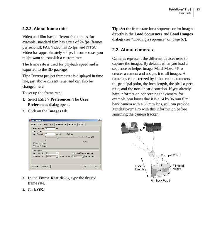
2.3. About cameras
Cameras represent the different devices used to capture the images. By default, when you load a sequence or helper image, MatchMover® Pro creates a camera and assigns it to all images. A camera is characterized by its internal parameters. the principal point, the focal length, the pixel aspect ratio, and the non-linear distortion. If you already have information concerning the camera, for example, you know that it is a 24 by 36 mm film back camera with a 35 mm lens, you can provide MatchMover® Pro with this information before launching the camera tracker.

Chapter 2Overview
14
The focal length is the distance between the film and the optical center of the lens when the lens is focused on infinity. The principal point represents the projection of the optical center onto the film back, perpendicular to the film back plane. The film back values represent the size of your film and is proportional to the pixel aspect ratio (see “Setting up cameras” on page 103 for more details).
2.3.1. About camera parameters
Each camera parameter has a value that you can provide or you can allow MatchMover® Pro to calculate it. The camera parameters—focal length, principal point, pixel aspect ratio, and non-linear distortion—vary or remain constant throughout the sequence and are either known or unknown.
2.3.1.1. Pixel aspect ratioProviding extra information to the camera tracker gives more accurate results with a faster calculation time. The pixel aspect ratio defines the aspect ratio of the sequence you render. If the sequence has square pixels, then the pixel aspect ratio is 1.
It is common, especially with video footage, to work with non-square pixels, such as in the image below. In these cases, the pixel ratio is different from 1.
In MatchMover® Pro, you may define the pixel aspect ratio for your sequence. As the pixel aspect ratio is dependent on the film back value, and vice-et-versa, changing the pixel aspect ratio also changes the film back value.
2.3.1.2. Non-linear distortionMathematical models of a perfect camera imply that the image of a straight line is always a straight line. However, real lenses are not always perfect and may introduce distortion into your footage. The effect of distortion is that straight lines become curved as shown in the following image.
MatchMover® Pro 3User Guide
15
MatchMover® Pro lets you input the radial distortion of your cameras if you know it, or will compute it if you don’t.
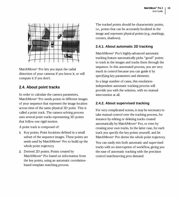
2.4. About point tracks
In order to calculate the camera parameters, MatchMover® Pro needs points in different images of your sequence that represent the image location across time of the same physical 3D point. This is called a point track. The camera solving process uses several point tracks representing 3D points that follow one rigid motion.A point track is composed of:1. Key points. Point locations defined in a small
subset of the sequence images. These points are seeds used by MatchMover® Pro to build up the whole point trajectory.
2. Derived 2D points. Points created by MatchMover® Pro based on information from the key points, using an automatic correlation-based template matching process.
The tracked points should be characteristic points, i.e., points that can be accurately localized in the image and represent physical points (e.g., markings, corners, shadows).
2.4.1. About automatic 2D tracking
MatchMover® Pro’s highly-advanced automatic tracking feature automatically picks “good” points to track in the images and tracks them through the sequence. In this automated process, you are very much in control because you can guide it by specifying key parameters and elements.In a large number of cases, this resolution-independent automatic tracking process will provide you with the solution, with no manual intervention at all.
2.4.2. About supervised tracking
For very complicated scenes, it may be necessary to take manual control over the tracking process, for instance by editing or deleting tracks created automatically by MatchMover® Pro, or even by creating your own tracks. In the latter case, for each track you specify the key points yourself, and let MatchMover® Pro derive the whole point trajectory.You can easily mix both automatic and supervised tracks with no interruption of workflow, giving you the ease of automatic tracking with the precision control matchmoving pros demand.

Chapter 2Overview
16
2.5. About mattes
MatchMover® Pro allows you to identify some areas within your sequence to either exclude them, focus on them, or flag them as objects following an independent motion.You can do so by either:
Cropping the image sequenceImporting a matte sequenceDrawing built-in animated polygons.
Image sequences may come with unnecessary black borders, which you can easily crop by resizing the cropping rectangle around the image. Cropping the image focuses the tracking process on the area you define, ignoring the unnecessary borders. Cropping is a global operation (applied on all frames), and it cannot be animated as mattes.Using a matte, you identify an area in the sequence that has a different motion. You can tell MatchMover® Pro to ignore it (e.g., a character occluding part of the background you want to track). You can also tell MatchMover® Pro to compute independent motions for areas lying inside and outside the matte (e.g., you want to compute the motion of the moving camera with respect to the fixed background, and at the same time the motion of a mobile object appearing in the sequence). In the latter case, both the background and the car will be tracked within the same solve.
MatchMover® Pro can import mattes made in other applications, or let you create your own mattes by drawing their outline. Both will then be combined.
Tip: You can combine the two operations of cropping an image then of excluding areas with a matte.
2.6. About 3D objects
MatchMover® Pro provides you with a set of objects called 3D primitives. 3D primitives are basic 3D shapes such as cubes, cones or spheres. It is also possible to import an object or a scene in the OBJ format. You can use a 3D object as it appears or edit it, using one of the manipulators. The virtual objects are fixed in space, and rendered using the estimated camera parameters. The process is successful when the motion of the virtual objects in the composed sequence is consistent with that of the real scene. You can also use 3D objects to define survey points mapping by dragging the mouse from one vertex to the image plane (see “Setting survey points using elastics” on page 115).
2.7. About camera computation
From the collection of 2D tracks, MatchMover® Pro estimates all camera parameters (internal parameters such as focal length and non-linear distortion, camera position and orientation over time, and 3D point coordinates). This represents a lot of parameters to compute (up to thousands), fortunately MatchMover® Pro does it for you automatically.

MatchMover® Pro 3User Guide
17
Depending on you production needs, you may want to feed MatchMover® Pro with some a priori information about the shot, thus constraining the process by reducing its parameter space.
2.7.1. About keyframes
A keyframe is a frame containing enough parameter data for the camera solving process. Using the data obtained from the 2D tracking process, MatchMover® Pro initializes the cameras and creates the 3D points for the sequence. The computation process will start on a rock-solid keyframe pair, called the reference frames (1 and 2). They are automatically chosen when launching the solver or when using the Select keyframes command if not locked by the user. Overriding the reference frames may help to solve complex shots when the chosen references are not well located, depending on the camera motion.
2.7.2. About relations on 3D points
Point relations are used by MatchMover® Pro as information about the geometry of the scene. This information can be:
That several points share a coordinate (for instance, all points on a horizontal plane, such as the ground, share the same Y value.Some points have known coordinates. This usually happens when you have measured survey points in your on-set. In this case, it may be simpler to use survey points.
When you provide MatchMover® Pro with information that helps the camera solving process, the results are more accurate.
2.7.3. About survey points
If you know some of the properties of a scene, because you took measurements, or you have some constraints, you may know the 3D coordinates of some points of the scene. Instead of letting MatchMover® Pro compute their 3D coordinates, you can set them before the computation. You can either set these coordinates manually or use one of your 3D object vertex coordinates.
2.7.4. About camera constraints
Camera constraints tell MatchMover® Pro that a parameter is constant over a subset of frames associated with a camera. As it reduces the number of computed parameters, it limits the calculation time and speeds up the process. MatchMover Pro has four types of constraints. Focal length, Nodal Pan, Dolly, and Planar.
2.7.5. About motion control
Some hardware devices, for example, Scorpio crane, Flair, output what we call “Motion Control Data”. You may be able to import it within MatchMover® Pro using the motion control file parser. This information will be directly input in the calibration engine, and used as an initial solution. It can therefore be refined, and additional camera parameters computed.

Chapter 2Overview
18
(See “Importing motion control data” on page 118). You can also override this data, or manually input some, this way constraining the final solution to a valid range you specified before launching the solver.

3
Tutorials


MatchMover® Pro 3User Guide
21
3.1. Basic tutorial
This tutorial teaches you the basics of matchmoving. You will learn how to track a sequence in 3D using MatchMover® Pro’s automatic tracking engine and inspect and export the result. In this tutorial, we assume that the user interface is in Light mode (the one you use when you first run MatchMover® Pro). However, the tutorial can also be carried out in Full mode. The footage used in this example was shot with a hand-held DV camcorder. In this tutorial you will learn how to:1. Import footage2. Use the automatic tracker to compute the 3D
camera path and the 3D scene3. Navigate in the project with a 3D view to
visualize and check the results4. Render a preview sequence5. Export the resultsTo access the data associate with the tutorial, either browse the CD-ROM (compact installation), go to /Applications/REALVIZ/MatchMover 3.0 Pro, or go to the directory where you have installed MatchMover® Pro and open the Tutorial/Basic folder.
3.1.1. Load the footage
1. Start MatchMover® Pro. By default, the application opens in Light mode.
2. Note: If you want to bypass this step, open Basic_Load_Sequence.mmf.Load the sequence by selecting File > Load Sequence or click on the Load Sequence icon
in the Tracking toolbar.
Chapter 3Tutorials
22
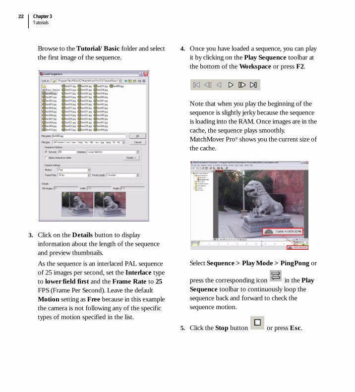
Browse to the Tutorial/Basic folder and select the first image of the sequence.
3. Click on the Details button to display information about the length of the sequence and preview thumbnails. As the sequence is an interlaced PAL sequence of 25 images per second, set the Interlace type to lower field first and the Frame Rate to 25 FPS (Frame Per Second). Leave the default Motion setting as Free because in this example the camera is not following any of the specific types of motion specified in the list.
4. Once you have loaded a sequence, you can play it by clicking on the Play Sequence toolbar at the bottom of the Workspace or press F2.
Note that when you play the beginning of the sequence is slightly jerky because the sequence is loading into the RAM. Once images are in the cache, the sequence plays smoothly. MatchMover Pro® shows you the current size of the cache.
Select Sequence > Play Mode > PingPong or
press the corresponding icon in the Play Sequence toolbar to continuously loop the sequence back and forward to check the sequence motion.
5. Click the Stop button or press Esc.

MatchMover® Pro 3User Guide
23
Tip: To play the scene manually, you can press Ctrl, click anywhere in the image, and drag the pointer to the left or to the right.
To go back to the first frame, press Ctrl+Home (Windows® and Linux only) or
Command+Home (Mac®) or press .
3.1.2. Run the automatic tracker
1. Run the automatic tracking by selecting 3D Tracking > Automatic Tracking, or press F10, or click the Run the Automatic Tracking
icon .A pop-up dialog appears, listing the steps in the automatic matchmoving process.
2. Now click Run to begin the matchmoving process. Colored indicators beside the option name show you the status of the process as well as the status of each step.
Depending on the size of the sequence, this process can take a bit of time. Note: If you want to bypass this step, open basic_Calibrated.mmf.At this stage, the camera path has been automatically computed, as well as a collection of 3D points. These 3D points are displayed as crosshairs in the workspace view and they also appears as colored icons in the Point Track
folder with an icon.
Chapter 3Tutorials
24
The colors indicate the quality of the tracking. green for good tracking, yellow for fair, and red for bad. Some grayed tracks are simply not reconstructed, which means the engine considered them too bad.
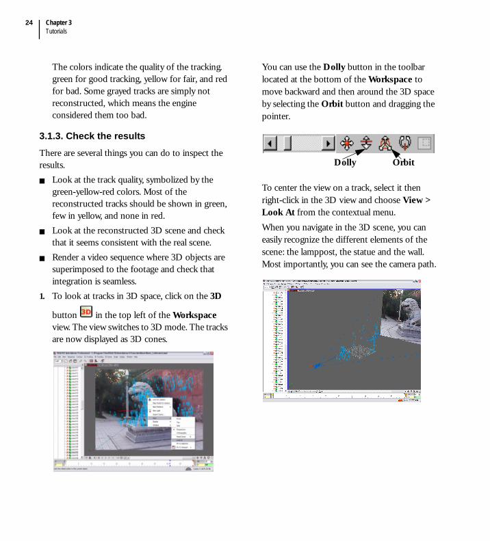
3.1.3. Check the resultsThere are several things you can do to inspect the results.
Look at the track quality, symbolized by the green-yellow-red colors. Most of the reconstructed tracks should be shown in green, few in yellow, and none in red.Look at the reconstructed 3D scene and check that it seems consistent with the real scene.Render a video sequence where 3D objects are superimposed to the footage and check that integration is seamless.
1. To look at tracks in 3D space, click on the 3D
button in the top left of the Workspace view. The view switches to 3D mode. The tracks are now displayed as 3D cones.
You can use the Dolly button in the toolbar located at the bottom of the Workspace to move backward and then around the 3D space by selecting the Orbit button and dragging the pointer.
To center the view on a track, select it then right-click in the 3D view and choose View > Look At from the contextual menu.When you navigate in the 3D scene, you can easily recognize the different elements of the scene: the lamppost, the statue and the wall. Most importantly, you can see the camera path.
Dolly Orbit

MatchMover® Pro 3User Guide
25
You can also switch to Lock on Camera mode
, to view through the computed camera with the image in the background. You can also judge the potential orientation of any elements that you might want to introduce into the scene with respect to the inclination of the 3D cones. Note: If the 3D cones are too large, change their size by selecting Edit > Preferences > Display (or press P) and change the default value of 1 to 0.5 in the 3D Helper Size text field.
Tip: P is a keyboard shortcut, by default attached to the Edit > Preferences action. Any action can be accessed by a keyboard shortcut, that you can define through the Keyboard tab of the Preferences dialog.
2. Now, you are going to render the scene in a video format to check the quality of the 3D tracking.
First, select 3D Scene > Render Setup.
Check the Setup/Browse button to select the output file and the format. Select the Antialiasing checkbox to inspect the result in fine detail. Set the Resolution to 50% for a first, quick preview and click on the Render button.

Chapter 3Tutorials
26
This pops up a window displaying a video sequence where 3D cones are composited to the initial footage. With a perfect tracking, the 3D cones should appear as if they were part of the scene. Otherwise, you would notice slight discrepancies between the motions of the real scene and of the 3D elements.
3. Now that you have automatically tracked a PAL video sequence and verified it by rendering it, you can export the results to your favorite animation or compositing package through the
File > Export menu . This will export the 3D points and the animated camera.
The available file formats are shown below.
3.2. Supervised tracking tutorial
This tutorial teaches you how to place tracks manually in a scene using MatchMover® Pro. The sequence you will use (Courtesy of Clear Ltd.) was taken against a green background using Pro material (camera, light, plate). The green background serves as a support for the actors and will be replaced by virtual decors. The blue crosses on the background allow you to track the scene.In the tutorial you will:
Load a sequenceCreate and edit tracks manuallyLaunch the solverDefine a coordinate systemAdd a 3D object to verify the tracked sequence.
To access the data associated with the tutorial, either browse the CD-ROM (compact installation), go to /Applications/REALVIZ/MatchMover 3.0 Pro, or go to the directory where you have installed MatchMover® Pro and open the Tutorial/Supervised_Tracking directory.

MatchMover® Pro 3User Guide
27
3.2.1. Load the footage
Note: If you want to bypass this step, open Shot_Loaded.mmf.
1. Start MatchMover® Pro. By default, the application opens in Light mode.
2. Switch to the Full mode by selecting Full from the drop-down menu in the Main Toolbar.
3. Load the sequence by selecting File > Load Sequence or click on the corresponding icon.
Browse to the Tutorial/Supervised_Tracking folder and select the sequence.
4. Click OK. MatchMover® Pro loads the sequence into the Workspace.
3.2.2. Create manual tracks
Note: If you want to bypass this step, open Shot_Tracked.mmf.
When you place tracks manually, try to cover as much of the scene as possible. For more information about placing tracks manually, see “Supervised 2D tracking” on page 83. We will place tracks on the most contrasted areas (in our example, mostly the blue crosses).

Chapter 3Tutorials
28
1. Track creationStart by selecting the 2D Tracking tab in the Main Toolbar.
We will now create a first track in the first frame of the sequence, at the location shown in the image below.
To create the track point, click on the
corresponding icon in the Main Toolbar, then click at the desired location. Alternatively, you can press Shift+right-click on the chosen area to both create the track and place it.
A pop-up window appears to help you place your track point precisely. If you have created it
too quickly, you can fine tune its position by clicking in the Magnifier window situated to the left of the Workspace.
Tip: If the magnification is too big, zoom out using the slide bar at the bottom of the window.
We choose corners areas to place the track points, because the extremities have less contrast and do not allow to visually locate the point as precisely as the intersections, thus introducing a higher risk of ending up with a “sliding” track point.
2. Basic tracking (tracking forward)While the track you have created is still selected,
run the 2D tracker forward by clicking on or by pressing the F3 key.
choosecorner area
MatchMover® Pro 3User Guide
29
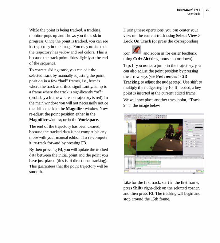
While the point is being tracked, a tracking monitor pops up and shows you the task in progress. Once the point is tracked, you can see its trajectory in the image. You may notice that the trajectory has yellow and red colors. This is because the track point slides slightly at the end of the sequence.To correct sliding track, you can edit the selected track by manually adjusting the point position in a few “bad” frames, i.e., frames where the track as drifted significantly. Jump to a frame where the track is significantly “off ” (probably a frame where its trajectory is red). In the main window, you will not necessarily notice the drift: check in the Magnifier window. Now re-adjust the point position either in the Magnifier window, or in the Workspace.The end of the trajectory has been cleared, because the tracked data is not compatible any more with your manual edition. To re-compute it, re-track forward by pressing F3.By then pressing F4, you will update the tracked data between the initial point and the point you have just placed (this is bi-directional tracking). This guarantees that the point trajectory will be smooth.
During these operations, you can center your view on the current track using Select View > Lock On Track (or press the corresponding
icon ) and zoom in for easier feedback using Ctrl+Alt+drag mouse up or down).Tip: If you notice a jump in the trajectory, you can also adjust the point position by pressing the arrow keys (see Preferences > 2D Tracking to adjust the nudge step). Use shift to multiply the nudge step by 10. If needed, a key point is inserted at the current edited frame. We will now place another track point, “Track 9” in the image below.
Like for the first track, start in the first frame, press Shift+right-click on the selected corner, and then press F3. The tracking will begin and stop around the 15th frame.

Chapter 3Tutorials
30
A popup appear, telling you that the tracking cannot go on.
Click OK. Notice that an element (here, the actor’s body) hides the area you want track in the sequence. Double-click on this frame.
Change the status of the keyframe as an “end” key by pressing on F7. This means you are not interested in tracking forward from this position.
You can check the status of the keyframe in the Parameters window on the right of the Workspace.
Keep track 09 selected then move forward frame by frame using Ctrl+right arrow until the corner re-appears. At the 29th frame, you will notice that it comes into view again. Simply click on the corner to place track 09 again.Since the track is likely to disappear again, you can track it image by image using the “step tracking mode”. Press Alt+right arrow to track the current selected point forward frame by frame. At each frame you may have to re-position the tracker, because of the proximity of the visual obstacles in front.The point disappears again, continue to move forward in the sequence until it reappears frame 44, place the track 09 again, and press the F3 key. Track 09 is now set in the sequence.
double-click

MatchMover® Pro 3User Guide
31
Tip: To visualize the quality of the Track 09 trajectory path, use the Magnifier window.
Click on the padlock symbol at the bottom right of the Magnifier window to make it the only active view.To verify the tracking quality, you can play the
sequence in Ping Pong mode with the Skip Untracked tool selected.
After checking the track, before continuing to create new track points, click again on the
padlock icon to make the main window active again. Uncheck the Skip Untracked option as well.
3. Tracking backwardContinue to place other points tracks in the sequence. For example, place a track point at the corner of the truck, near the white wheel the last frame at the end of the sequence (Track 10 in our example). After creating the corner point, press F3 to track backward or click on the
corresponding icon in the 2D Tracking tab in the Main Toolbar to track the scene backward.
You will notice that the tracking path slides away from the corner and starts tracking another object because the singer’s arm covers the corner where you placed the track.To correct the track, zoom in slightly, click on
the Lock On Track icon to look closely at the path behavior.Move backward frame by frame using Ctrl+left arrow. Around frame 25, notice that you need to stop the track path because the track starts diverging from the corner. To do so, simply nudge the track position by pressing the arrow keys. This creates an intermediate point and erases the rest of the trajectory.
move up with arrow key

Chapter 3Tutorials
32
3.2.3. Supervised tracking
Add other points, for instance at the locations shown in the image below. Note: If you want to bypass this step, open Shot_Solved.mmf in the Data directory.
3.2.4. Calibrate the cameras
Note: If you want to bypass this step, open Shot_Solved.mmf.1. Run the calibration by selecting 3D Tracking >
Solve for Camera, or click on the icon , or clicking on F9.
2. Once the calibration is finished, switch to the
3D mode by pressing the 3D mode button in the top left corner of the Workspace.
3. Right-click and select View > Lock On Camera from the contextual menu or click the
icon and play the sequence to check the tracking.
3.2.5. Create a coordinate system
Note: If you want to bypass this step, open Shot_Coordsys.mmf.To set up the coordinate system.1. In the Project Tree, right-click on the
Coordinate Systems folder and select New Coordinate System.
2. In the Parameters window to the right of the Workspace, enter the coordinate system values. Select a track that it on the ground of the scene (for example, Track05) as the “Origin”. This point is the center of the grid and also the floor of the scene.
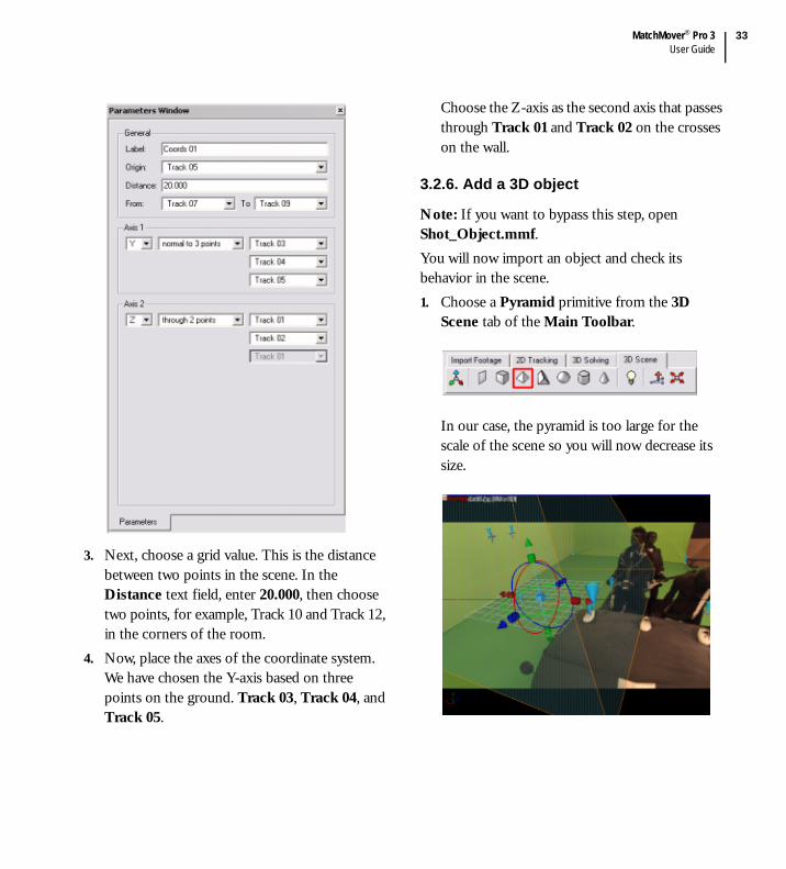
MatchMover® Pro 3User Guide
33
3. Next, choose a grid value. This is the distance between two points in the scene. In the Distance text field, enter 20.000, then choose two points, for example, Track 10 and Track 12, in the corners of the room.
4. Now, place the axes of the coordinate system. We have chosen the Y-axis based on three points on the ground. Track 03, Track 04, and Track 05.
Choose the Z-axis as the second axis that passes through Track 01 and Track 02 on the crosses on the wall.
3.2.6. Add a 3D object
Note: If you want to bypass this step, open Shot_Object.mmf.You will now import an object and check its behavior in the scene.1. Choose a Pyramid primitive from the 3D
Scene tab of the Main Toolbar.
In our case, the pyramid is too large for the scale of the scene so you will now decrease its size.

Chapter 3Tutorials
34
2. If the pyramid object is not selected, you can select it by clicking on it in the Workspace (in 3D mode) or simply click on the Pyramid name in the Project Tree / 3D Scene sub-folder.
3. Once selected, you can press the Tab key to select the scaling tools.
4. Click and drag the blue handles at the ends of the cube inward to decrease the size of the pyramid. Note that the dimensions of the pyramid stay in proportion.
5. Next, select the dark blue arrow and move the pyramid slightly along the Z-axis toward the back on the scene. You can also move the pyramid along the X-axis.
6. Play the sequence in Ping-Pong mode. The pyramid stays on the floor of the scene.
You have completed the tutorial. You have created and edited manual tracks, verified the scene by importing an object and checking its behavior in the scene. Now you are ready to export the scene
.
3.3. Object-based tracking with elastics tutorial
This tutorial teaches you how to track a scene or an object in MatchMover® Pro using a 3D model of the scene/object. This is particularly useful for a lot of applications:
Augmenting a real set for which some 3D information is available as manual measurements or CAD data

MatchMover® Pro 3User Guide
35
Matchmoving characters from a Cyberware® scanTracking complex shots of a set using data from an active scanning device (LIDAR).
It guarantees that in any case (even with low or zero parallax), the camera path will be exactly consistent with the 3D geometry of the tracked element.The sequence was shot using a hand-held DV camcorder.In this tutorial you will learn how to:
Import a 3D meshCreate tracks and survey points attached to vertices of the mesh, using the “elastics” feature.
To access the data associated with the tutorial, either browse the CD-ROM (compact installation), go to /Applications/REALVIZ/MatchMover Pro/3.0/Tutorial/Elastics, or go to the directory where you have installed MatchMover® Pro and open the Tutorial/Elastics directory.
3.3.1. Load the footage
1. Start MatchMover® Pro. Make sure the interface is in Full mode.
2. Note: If you want to bypass this step, open Elastic_Load_Sequence.mmf.Load the sequence by selecting File > Load Sequence. Browse to the Tutorial/Elastics folder and select the sequence.
Set the Interlace type to lower field first and the Frame Rate to 25 FPS (Frame Per Second). Leave the default Motion setting as Free.
3.3.2. Import the 3D mesh
Note: If you want to bypass this step, open Elastic_Import_Scene.mmf.
1. Put the view in 3D mode using the button.

Chapter 3Tutorials
36
2. Select File > Import… or Import Scene from the contextual menu.
Select the file named “Box.obj”.
The 3D mesh of the box appears in wireframe, in front of the image plane. This mesh will now be used as a reference for the 3D tracking, guaranteeing that the solution will be consistent with this geometry even though this shot holds little parallax.
3.3.3. Set up the trackers and the survey points
Note: If you want to bypass this step, open Elastic_SetUp_Elastics.mmf.
1. Using the view pan and dolly controls, make sure both the 3D object representing the shape of the box and the image plane are clearly visible. For instance, set up your viewing position and angle as in the next screen shot.

MatchMover® Pro 3User Guide
37
2. Make sure that the Magnifier window is open using Window > Magnifier Window.
3. Click on a vertex of the 3D box and, while keeping the button pressed, move the cursor to the position of the same corner in the image plane. While you are dragging the cursor, you can see a red elastic line joining it to the selected vertex.
When you release the button, the elastic becomes blue. A new track is created with a point in the current frame (visible in the track view). The survey point information issued from the selected vertex is automatically associated to the track, as shown by the icon in the track view and by the Survey Info tab of the track properties.
Note: If you want to abort the operation while dragging the mouse, simply drag the mouse out of the image plane. The elastic line becomes dashed, meaning nothing will happen when you release the button.
4. If necessary, refine the position of the image point by clicking it in the Magnifier window (if necessary, adjust the magnifier zoom factor using the horizontal slider at the bottom).
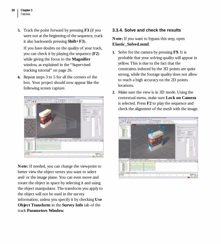
Chapter 3Tutorials
38
5. Track the point forward by pressing F3 (if you were not at the beginning of the sequence, track it also backwards pressing Shift+F3).If you have doubts on the quality of your track, you can check it by playing the sequence (F2) while giving the focus to the Magnifier window, as explained in the “Supervised tracking tutorial” on page 26.
6. Repeat steps 3 to 5 for all the corners of the box. Your project should now appear like the following screen capture.
Note: If needed, you can change the viewpoint to better view the object vertex you want to select and/or the image plane. You can even move and rotate the object in space by selecting it and using the object manipulator. The transform you apply to the object will not be used in the survey information, unless you specify it by checking Use Object Transform in the Survey Info tab of the track Parameters Window.
3.3.4. Solve and check the results
Note: If you want to bypass this step, open Elastic_Solved.mmf.
1. Solve for the camera by pressing F9. It is probable that your solving quality will appear in yellow. This is due to the fact that the constraints induced by the 3D points are quite strong, while the footage quality does not allow to reach a high accuracy on the 2D points locations.
2. Make sure the view is in 3D mode. Using the contextual menu, make sure Lock on Camera is selected. Press F2 to play the sequence and check the alignment of the mesh with the image.

4
Interface Guide


MatchMover® Pro 3User Guide
41
1. Interface guide
4.1. Interface overview
When you start MatchMover® Pro, you are presented with the following user interface.
This is what we call the “Light Mode”. This mode is designed for simple automatic worfkflows. The interface displays only the tools that allow you to load, autotrack, and export a sequence.
Note: All windows are fully floatable/dockable/resizable/hideable. Double click on a window title to toggle the display status.
Use the interface mode selector in the Standard Toolbar to switch the interface to ‘Full Mode”.
A number of menu items appear in the Main Menu bar. If a shortcut is available, it is shown next to the menu entry. Some of the drop-down menu functions are available directly through toolbar icons and keyboard shortcuts.
Toolbars
Time Line
Status Bar
Main Menu
Workspace
Project Window
Main Menu Workspace
Project Window Actions Stack
Toolbars
Time LineStatus BarTrack Window
Parameters Window
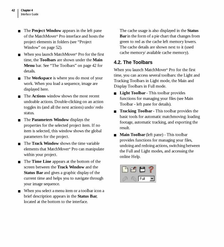
Chapter 4Interface Guide
42
The Project Window appears in the left pane of the MatchMover® Pro interface and hosts the project elements in folders (see “Project Window” on page 52).When you launch MatchMover® Pro for the first time, the Toolbars are shown under the Main Menu bar. See “The Toolbars” on page 42 for details.The Workspace is where you do most of your work. When you load a sequence, image are displayed here. The Actions window shows the most recent undoable actions. Double-clicking on an action toggles its (and all the next actions) undo/redo status.The Parameters Window displays the properties for the selected project item. If no item is selected, this window shows the global parameters for the project. The Track Window shows the time variable elements that MatchMover® Pro can manipulate within your project.The Time Line appears at the bottom of the screen between the Track Window and the Status Bar and gives a graphic display of the current time and helps you to navigate through your image sequence.When you select a menu item or a toolbar icon a brief description appears in the Status Bar, located at the bottom to the interface.
The cache usage is also displayed in the Status Bar in the form of a pie chart that changes from green to red as the cache left memory lowers. The cache details are shown next to it (used cache memory/available cache memory).
4.2. The ToolbarsWhen you launch MatchMover® Pro for the first time, you can access several toolbars: the Light and Tracking Toolbars in Light mode, the Main and Display Toolbars in Full mode.
Light Toolbar - This toolbar provides functions for managing your files (see Main Toolbar - left pane for details).Tracking Toolbar - This toolbar provides the basic tools for automatic matchmoving: loading footage, automatic tracking, and exporting the result.Main Toolbar (left pane) - This toolbar provides functions for managing your files, undoing and redoing actions, switching between the Full and Light modes, and accessing the online Help.

MatchMover® Pro 3User Guide
43
Note: In MatchMover® Pro, you use the Undo
icon and the Redo icon to undo or redo, respectively, the last action. The Undo Buffer holds data required to undo/redo actions. In addition the Actions Stack window shows the most recent undoable actions.
Actions completed are denoted by the icon
and actions undone by the icon .
This stack is of limited size. Double-clicking on an action toggles its (and all the next actions) undo/redo status.
Main Toolbar (right pane) - This toolbar provides functions for importing footage, the management of your 2D tracking process, the camera solving, and 3D object manipulation.
Display Toolbar - This toolbar provides access to the track display options and the layout of the Workspace.
4.3. The Workspace
The first time you launch MatchMover® Pro, the Workspace is empty. Once you load an image sequence, the frames of the sequence are shown in the Workspace. The file name and size of the current frame are displayed next to current time.
4.3.1. Switching between the 2D and 3D mode
By default, a 2D View (a viewport in 2D mode) is shown. You can reset or change the view type by using Window > New View and select the required view. As soon as a sequence or images are loaded, the 3D View (a viewport in 3D mode) is available, with a default camera looking at the origin. The view can be used for example to estimate distortion, by just shifting its value in the curve editor, or to place 3D object and map survey points.
Use the 2D Mode button and the 3D Mode
button in the top left corner of the Workspace to toggle between the 2D and the 3D views.For more information on the different views, see “Working in2D mode” on page 44 and “Working in 3D Mode” on page 48.

Chapter 4Interface Guide
44
4.3.2. Changing the viewport layout
You can split the Workspace into two or four viewports by selecting Window > Layout from the main menu and the required split option.Alternatively, you can click on the icons in the Display Toolbar to change the viewport layout. The icons with their description are shown in the following table:
Tip: Press the Spacebar to return to a single viewport from multiple viewports.
If split, one of the viewports is outlined as the current view. For example, the Project Window may be the currently activated window while the last edited viewport remains current and receives any viewing action coming from the Project Window or from the main menu.
To switch between the Full Screen mode and the
normal mode, click on the Full Screen icon in the Display Toolbar.
4.3.3. Resizing viewports
When you have several viewports in the workspace, you can change their size. Click on the border of a view and drag the pointer to resize the view.Tip: Reclicking on the current layout icon just reset to default layout geometry. Reclicking on single viewport icon just toggle between single and previous layout.
4.4. Working in2D mode
MatchMover® Pro provides you with the ability to open different views within the Workspace window to study and manipulate the image sequence and the results of the tracking process. When you load a sequence, the default view is the 2D View. The 2D View is designed to display single images, image sequences and tracking information to help in your 2D tracking task. The following list shows all items that are drawn in the 2D View:
Images, helper images and matte sequences.The current and local times of the frames in the upper left corner. Masks (see “Identifying image regions” on page 70).
Icon Menu Item Opens...
Single Viewport
A single viewport
Two Stacked Two stacked viewports
Two Side by Side
Two side by side viewports
Four Viewports
Four viewports
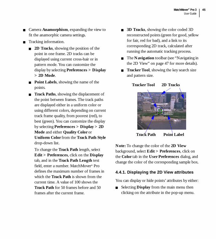
MatchMover® Pro 3User Guide
45
Camera Anamorphism, expanding the view to fit the anamorphic camera settings.Tracking information.
2D Tracks, showing the position of the point in one frame. 2D tracks can be displayed using current cross-hair or in pattern mode. You can customize the display by selecting Preferences > Display > 2D Mode.Point Labels, showing the name of the points.Track Paths, showing the displacement of the point between frames. The track paths are displayed either in a uniform color or using different colors, depending on current track frame quality, from poorest (red), to best (green). You can customize the display by selecting Preferences > Display > 2D Mode and either Quality Color or Uniform Color from the Track Path Style drop-down list.To change the Track Path length, select Edit > Preferences, click on the Display tab, and in the Track Path Length text field, enter a number. MatchMover® Pro defines the maximum number of frames in which the Track Path is shown from the current time. A value of 100 shows the Track Path for 50 frames before and 50 frames after the current frame.
3D Tracks, showing the color coded 3D reconstructed points (green for good, yellow for fair, red for bad), and a link to its corresponding 2D track, calculated after running the automatic tracking process.The Navigation toolbar (see “Navigating in the 2D View” on page 47 for more details).Tracker Tool, showing the key search size and pattern size.
Note: To change the color of the 2D View background, select Edit > Preferences, click on the Color tab in the User Preferences dialog, and change the color of the corresponding sample box.
4.4.1. Displaying the 2D View attributes
You can display or hide points’ attributes by either:Selecting Display from the main menu then clicking on the attribute in the pop-up menu.
Tracker Tool 2D Tracks
Point LabelTrack Path

Chapter 4Interface Guide
46
Right-clicking in the 2D View and selecting Display and an attribute from the contextual menu.
For the Masks and Anamorphism options, a checkmark beside the option indicates that the option is active. Clicking the option again hides the checkmark and deactivates it.
For other attributes, a single diamond shown beside the attribute in the menu defines that the attribute is displayed for the selected point.
If you click again, two diamonds appear beside the attribute defining that the selected attribute is displayed for all points. No diamonds means this feature is not displayed. By default the Point Label, Track Path, Tracker Tool, and Tracking Score are only displayed for the selected key point or computed point.
Note: To change the color of the Track Path (in uniform color mode) or the key points on the track, select Edit > Preferences, click on the Color tab in the User Preferences dialog, and change the color of the corresponding sample box.
4.4.2. Changing the time in the 2D View
The 2D View shows an image at a given time. The current time is shown in the top left corner of the viewport.
To change the current time, press Ctrl+click and drag the pointer. The pointer changes to
.
To move to the previous frame, press Ctrl+left arrow.To move to the next frame, press Ctrl+right arrow.To reset the current time to the beginning of the sequence, right-click on the required sequence in the Image Sequences folder in the Project Window and select Goto Begin from the contextual menu.
To hide the current time, select Edit > Preferences > Display and click in the Show Current Time in Viewports checkbox to disable the option.Tip: If nothing is currently selected, just pressing arrows navigate through time/zoom.
4.4.3. Freezing the time
By default, time changes in the Time Line or other 2D views are always synchronized with current time. However, when you “freeze” the 2D View, changing the time in other views (the Time Line, the Track Window or other 2D Views) does not affect the time in the frozen view. Other views are not synchronized with current time. If you change the time in the frozen view, other views are synchronized with the current time in the frozen view. The Freeze Time mode is useful if you need to study frames at different times, for example, when you have multiple 2D views and need to see them at a certain time, for instance when editing tracks in a helper frame.

MatchMover® Pro 3User Guide
47
The shortcuts Ctrl+left arrow or right arrow change the time in the frozen window only if the window is active (blue surround).To freeze the time in the 2D View, do one of the following:
Select View > Freeze Time.
Select the Freeze Time icon in the Display Toolbar.Right-click in the 2D View to show the contextual menu and select Freeze Time.
4.4.4. Resetting the current view
To reset the current view, select Window > New View > New 2D View or press Ctrl+2 (default shortcut.
4.4.5. Navigating in the 2D ViewYou can access the navigation options in the View menu. Alternatively, use the following shortcuts and drag the pointer in the 2D View, Track View, Graph Editor, and Track Status View.
#Pan horizontally only in the Track View, Graph Editor, and Track Status View
In the 2D View:
Click on the Pan icon in the Navigation Toolbar at the bottom of the window and drag the pointer to perform the navigation.
Use the scroll buttons to scroll through the images.
Click on the Navigator button to easily pan in the entire image.
In addition to the navigation options shown in the previous table, you can right-click in the 2D View and select the following options from the contextual menu.
To center the view on the selected item, select View > Fit to Selection.
Action Shortcut Pointer
Changes the current time
Ctrl+click
Move to next frame
Ctrl+right arrow
-
Move to previous frame
Ctrl+left arrow -
Pan# Alt+click(or scroll bars)
Zoom Alt+Ctrl+click(or “+” or “-”)
Zoom in an area in the 2D View
Alt+Shift+click
Action Shortcut Pointer

Chapter 4Interface Guide
48
To set the largest zoom that keeps the entire image contained in the viewport select View > Fit to Viewport.
Note: You can also click on the
Fit to Viewport icon in the Display Toolbar.
If you have zoomed the image you can return to the original size with View > Reset zoom.
4.5. Working in 3D Mode
The 3D View shows the following from an arbitrary viewpoint:
CamerasTracking information.
Point Labels, showing the point names.3D Markers, or 3D Helpers, displaying the estimated 3D points as customizable 3D Helpers (cones, pyramids, points). A link is drawn between the 2D reprojections and the corresponding 3D points if available.Manipulator AxesA 3D planar GridNon-physical objects. Lights and RelationsBuilt-in contoursThe estimated Camera Path.
The reference coordinate system
3D objects created directly in MatchMover® Pro or imported (see “Working with 3D objects” on page 135).
The default 3D View is in the Free Camera mode with the image plane displayed. By clicking on the image plane, you are able to tweak its displayed depth by using the displayed translation manipulator.Toggle the image plane display by selecting Display > Background Image.
In the 3D View window you can switch to Lock on Camera mode (see “Lock on Camera mode” on page 50). The view is constrained to be seen from the camera with the image as the background.When you place a 3D object within the 3D View window, MatchMover® Pro provides manipulators that you can use to edit them. See “Editing 3D primitives and objects” on page 136.
MatchMover® Pro 3User Guide
49
Note: To change the color of the 3D View background, the camera, or the camera path, select Edit > Preferences, click on the Color tab in the the User Preferences dialog, and change the color of the corresponding sample box.
Note: To reset the current 3D View, see “Resetting the current view” on page 47.
You can create tracks in the 3D View in the same way as in the 2D View. See “Working in 3D Mode” on page 48 for details abour creating new tracks.
4.5.1. Displaying the 3D View attributes
By default the 3D View shows a grid and axes with a perspective viewing, the camera path with its corresponding image plane, and the reconstructed points. You can display or hide points’ attributes by either:
Selecting Display from the main menu then clicking on the attribute in the pop-up menu.Right-clicking in the 3D View and selecting Display and an attribute from the contextual menu.
For Point Labels and 3D Marker Styles attributes, a single diamond defines that the attribute is displayed for the selected point. If you click again, two diamonds appear beside the attribute defining that the selected attribute is displayed for all points. No diamonds means that this attribute is not displayed.
For all other options, a checkmark beside the option indicates that the option is active. Clicking the option again hides the checkmark and deactivates it.You can also toggle the 3D object display in the Display menu:
Flat shadingWireframe. A backface culling option for wireframe mode also exists in the Display menu.TransparentTexture mode.
Tip: The default shading is smooth. See the Preferences dialog to change it to real flat shading.
4.5.2. Changing the number of wireframe divisions
You can change the number of divisions in the wireframe of a selected object in the 3D View mode.1. Select Edit > Preferences.2. Enter a number in the 3D Primitive
Resolution text field. A smaller number reduces the size of the intervals in the wireframe grid; a greater number decreases their size.
Note: The 3D Primitive Resolution is also reported in the Global Parameters Window.
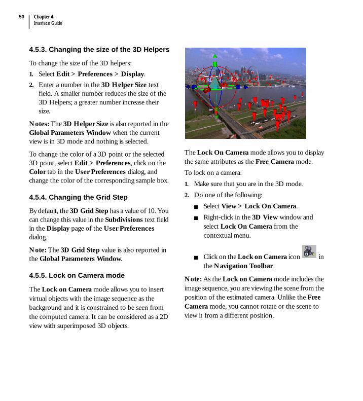
Chapter 4Interface Guide
50
4.5.3. Changing the size of the 3D Helpers
To change the size of the 3D helpers:1. Select Edit > Preferences > Display.2. Enter a number in the 3D Helper Size text
field. A smaller number reduces the size of the 3D Helpers; a greater number increase their size.
Notes: The 3D Helper Size is also reported in the Global Parameters Window when the current view is in 3D mode and nothing is selected.
To change the color of a 3D point or the selected 3D point, select Edit > Preferences, click on the Color tab in the User Preferences dialog, and change the color of the corresponding sample box.
4.5.4. Changing the Grid Step
By default, the 3D Grid Step has a value of 10. You can change this value in the Subdivisions text field in the Display page of the User Preferences dialog.
Note: The 3D Grid Step value is also reported in the Global Parameters Window.
4.5.5. Lock on Camera mode
The Lock on Camera mode allows you to insert virtual objects with the image sequence as the background and it is constrained to be seen from the computed camera. It can be considered as a 2D view with superimposed 3D objects.
The Lock On Camera mode allows you to display the same attributes as the Free Camera mode.To lock on a camera:1. Make sure that you are in the 3D mode.2. Do one of the following:
Select View > Lock On Camera.Right-click in the 3D View window and select Lock On Camera from the contextual menu.
Click on the Lock on Camera icon in the Navigation Toolbar.
Note: As the Lock on Camera mode includes the image sequence, you are viewing the scene from the position of the estimated camera. Unlike the Free Camera mode, you cannot rotate or the scene to view it from a different position.

MatchMover® Pro 3User Guide
51
4.5.6. Navigating in the 3D View
You can access the navigation options in the 3D View in the View menu or in the toolbar located at the bottom of the Workspace.
Use the slider to scroll through the images.Alternatively, you can use the following shortcuts and dragging the pointer.
By right-clicking in the 3D View, you can turn the camera toward the selected item by selecting View > Look At from the contextual menu.
4.6. Browsing the footage
Once you have loaded a sequence, you can play it by clicking on the Play Sequence toolbar at the bottom of the Workspace.
The Play Sequence toolbar from left to right is described below.
First Frame - Navigates to the first frame of the sequence.Previous Frame - Changes the current time to point to the preceding frame.Play Reverse - Runs the play segment backwards.
Action Shortcut Pointer
Changes the current time
Ctrl+click
Dolly Alt+Ctrl+click
Fit to rectangle Alt+Shift+click
Move to next frame
Ctrl+right arrow
-
Move to previous frame
Ctrl+left arrow -
Pan
Dolly
Orbit
RollSlider
Orbit in the Free Camera mode
Alt+right-click
Pan Alt+click(or scroll bars)
Zoom Alt+Ctrl+right-click(or “+” or “-”)
Action Shortcut Pointer
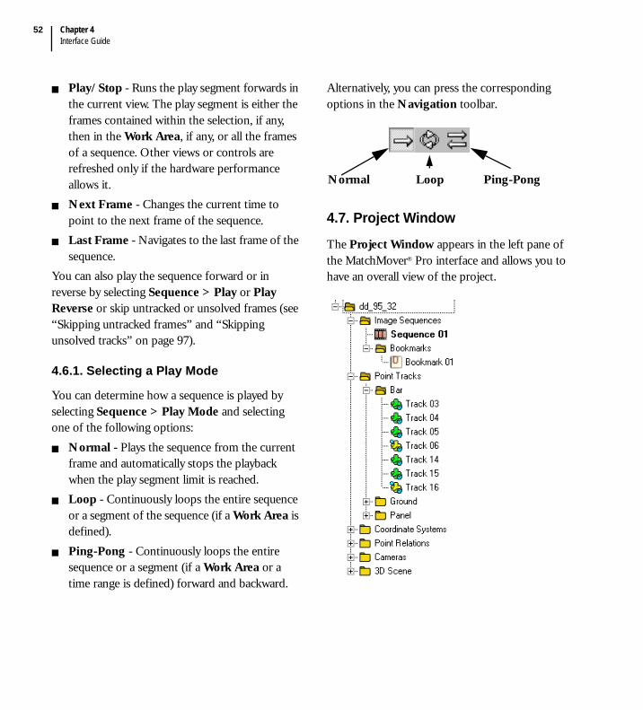
Chapter 4Interface Guide
52
Play/Stop - Runs the play segment forwards in the current view. The play segment is either the frames contained within the selection, if any, then in the Work Area, if any, or all the frames of a sequence. Other views or controls are refreshed only if the hardware performance allows it. Next Frame - Changes the current time to point to the next frame of the sequence.Last Frame - Navigates to the last frame of the sequence.
You can also play the sequence forward or in reverse by selecting Sequence > Play or Play Reverse or skip untracked or unsolved frames (see “Skipping untracked frames” and “Skipping unsolved tracks” on page 97).
4.6.1. Selecting a Play Mode
You can determine how a sequence is played by selecting Sequence > Play Mode and selecting one of the following options:
Normal - Plays the sequence from the current frame and automatically stops the playback when the play segment limit is reached.Loop - Continuously loops the entire sequence or a segment of the sequence (if a Work Area is defined).Ping-Pong - Continuously loops the entire sequence or a segment (if a Work Area or a time range is defined) forward and backward.
Alternatively, you can press the corresponding options in the Navigation toolbar.
4.7. Project Window
The Project Window appears in the left pane of the MatchMover® Pro interface and allows you to have an overall view of the project.
Normal Loop Ping-Pong

MatchMover® Pro 3User Guide
53
The Project Window shows all the elements that can be manipulated by MatchMover® Pro. You can also create, delete or launch an action in the Project Window. The tree structure organization aids in arranging and managing your project.
Click to close the Project Window.To restore the view, select Window > Project WindowSome Project Window elements appear in bold. Only one element of a given type can be bold at a given moment. For example, an image sequence label is bold if the current time corresponds to an image of this sequence. A coordinate system label is bold if it is used to calculate or show 3D information. A camera label is bold if it is associated with the enabled image sequence. A constraint label is bold if it is defined for the current time.
4.7.1. Project Window folders
The Project Window folders contain the elements of your project. To expand or collapse a folder, click on the + or - symbols to show the list of all the elements within the folder.
Image Sequences - Contains the list of images, image sequences, contour, mattes and the sub-folders Bookmarks containing shortcuts to images.
Point Tracks - Contains the list of point tracks and groups created.
All tracks can be sorted in groups. See “Groups attributes” on page 98. A group can be designated as mobile (designing a rigid moving object) by selecting the Mobile option in the
Parameters Window .Hidden tracks are dimmed and they are not displayed in the 2D View or in the 3D View. They can still be rendered by selecting the corresponding option in the Render dialog.
Coordinate Systems - Contains the list of coordinate systems that can be used to represent the 3D data.Point Relations - Contains the list of defined relations between point tracks.Cameras - Contains the list of cameras and their relative sub-folders containing the camera constraints defined for them, if any. Empty constraints are dimmed with “empty” after their label. You should add frames to any constraint before using it.3D Scene - Contains the 3D scene elements of a project.
Click on an element to open its properties in the Parameters Window.

Chapter 4Interface Guide
54
4.8. Track Window
The Track Window contains two separate panes; each pane reacts in synchronization with the other, and shows the time variable elements that MatchMover® Pro can manipulate within your project. Scroll through the Track View, the Graph Editor, and the Track Status View by clicking on the tabs at the bottom of the window, just above the Time Line (see “Interface overview” on page 41).
Click to close the Track Window. To restore the view, select Window > Track Window.
4.8.1. The Track View
The Track View is used mainly for supervised 2D tracking (see “Supervised 2D tracking” on page 83). The left pane is a sub section of the Project Window showing the elements contained in your project in relation to time (see “Project Window” on page 52). Within the right pane of the Track View, symbols are used to give a graphic representation of the elements and their state.
The Time Bar is a double vertical bar represents the current time. Double-click in the right pane to move the Time Bar to the required frame. The Graded Ruler shows the position of the current time in the sequence. Click and drag the ruler to move it vertically within the pane. Symbols in the Graded Ruler indicate whether the frame is a reference frame, and or a
keyframe . If it is yellow , the keyframes are automatically generated and unlocked; otherwise, they are locked. The Graded Ruler also shows information about the 3D solving status of each frame (see “Checking the computation quality in the Track Window” on page 123). A lock icon is displayed on the right-end of the Graded Ruler that enables easy keyframes locking/unlocking
.The Time Range allows you to select a group of frames, also displayed in the Time Line (see “Time Line Window” on page 57).
The shape of a point indicates whether the point is a key point or a computed point, and the type of tracking generated (see “Editing a key point type” on page 87 for more details).
Time Bar
Graded RulerTime Range
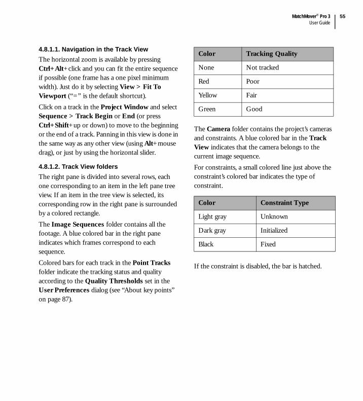
MatchMover® Pro 3User Guide
55
4.8.1.1. Navigation in the Track ViewThe horizontal zoom is available by pressing Ctrl+Alt+click and you can fit the entire sequence if possible (one frame has a one pixel minimum width). Just do it by selecting View > Fit To Viewport (“=” is the default shortcut).Click on a track in the Project Window and select Sequence > Track Begin or End (or press Ctrl+Shift+up or down) to move to the beginning or the end of a track. Panning in this view is done in the same way as any other view (using Alt+mouse drag), or just by using the horizontal slider.
4.8.1.2. Track View foldersThe right pane is divided into several rows, each one corresponding to an item in the left pane tree view. If an item in the tree view is selected, its corresponding row in the right pane is surrounded by a colored rectangle.The Image Sequences folder contains all the footage. A blue colored bar in the right pane indicates which frames correspond to each sequence.Colored bars for each track in the Point Tracks folder indicate the tracking status and quality according to the Quality Thresholds set in the User Preferences dialog (see “About key points” on page 87).
The Camera folder contains the project’s cameras and constraints. A blue colored bar in the Track View indicates that the camera belongs to the current image sequence. For constraints, a small colored line just above the constraint’s colored bar indicates the type of constraint.
If the constraint is disabled, the bar is hatched.
Color Tracking Quality
None Not tracked
Red Poor
Yellow Fair
Green Good
Color Constraint Type
Light gray Unknown
Dark gray Initialized
Black Fixed
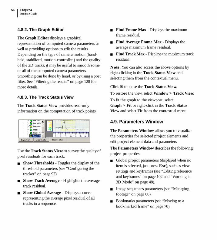
Chapter 4Interface Guide
56
4.8.2. The Graph Editor
The Graph Editor displays a graphical representation of computed camera parameters as well as providing options to edit the results. Depending on the type of camera motion (hand-held, stabilized, motion-controlled) and the quality of the 2D tracks, it may be useful to smooth some or all of the computed camera parameters. Smoothing can be done by hand, or by using a post filter. See “Filtering the results” on page 128 for more details.
4.8.3. The Track Status View
The Track Status View provides read-only information on the computation of track points.
Use the Track Status View to survey the quality of pixel residuals for each track.
Show Thresholds - Toggles the display of the threshold parameters (see “Configuring the tracker” on page 92).Show Track Average - Highlights the average track residual.Show Global Average - Displays a curve representing the average pixel residual of all tracks in a sequence.
Find Frame Max - Displays the maximum frame residual.Find Average Frame Max - Displays the average maximum frame residual.Find Track Max - Displays the maximum track residual.
Note: You can also access the above options by right-clicking in the Track Status View and selecting them from the contextual menu.
Click to close the Track Status View.To restore the view, select Window > Track View.To fit the graph to the viewport, select Graph > Fit or right-click in the Track Status View and select Fit from the contextual menu
4.9. Parameters Window
The Parameters Window allows you to visualize the properties for selected project elements and edit project element data and parametersThe Parameters Window describes the following: project properties:
Global project parameters (displayed when no item is selected, just press Esc), such as view settings and keyframes (see “Editing reference and keyframes” on page 102 and “Working in 3D Mode” on page 48).Image sequences parameters (see “Managing footage” on page 66).Bookmarks parameters (see “Moving to a bookmarked frame” on page 70).
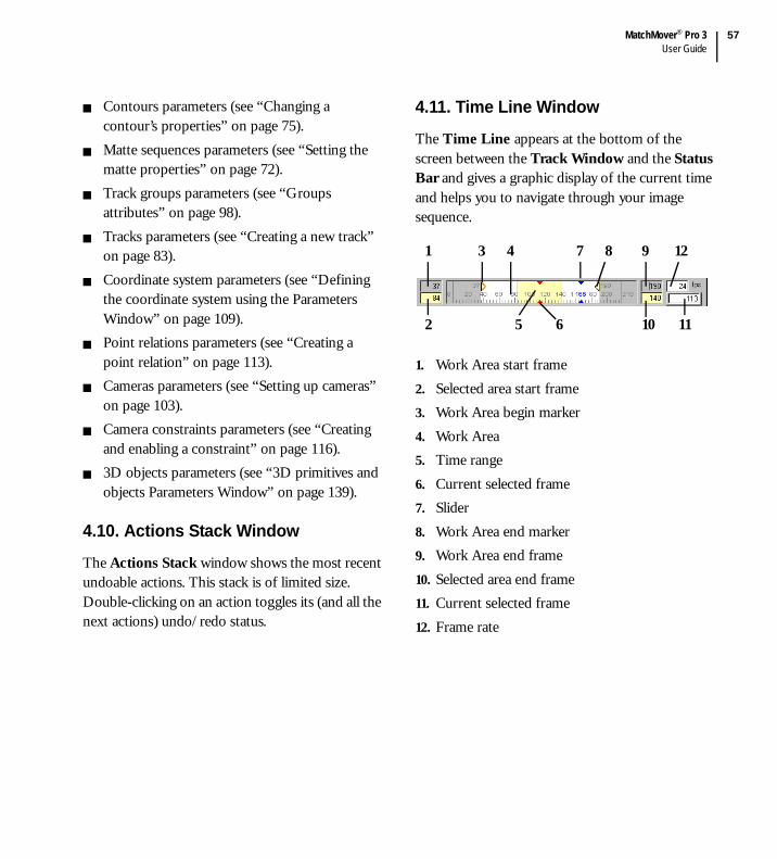
MatchMover® Pro 3User Guide
57
Contours parameters (see “Changing a contour’s properties” on page 75).Matte sequences parameters (see “Setting the matte properties” on page 72).Track groups parameters (see “Groups attributes” on page 98).Tracks parameters (see “Creating a new track” on page 83).Coordinate system parameters (see “Defining the coordinate system using the Parameters Window” on page 109).Point relations parameters (see “Creating a point relation” on page 113).Cameras parameters (see “Setting up cameras” on page 103).Camera constraints parameters (see “Creating and enabling a constraint” on page 116).3D objects parameters (see “3D primitives and objects Parameters Window” on page 139).
4.10. Actions Stack Window
The Actions Stack window shows the most recent undoable actions. This stack is of limited size. Double-clicking on an action toggles its (and all the next actions) undo/redo status.
4.11. Time Line Window
The Time Line appears at the bottom of the screen between the Track Window and the Status Bar and gives a graphic display of the current time and helps you to navigate through your image sequence.
1. Work Area start frame2. Selected area start frame3. Work Area begin marker 4. Work Area5. Time range6. Current selected frame7. Slider8. Work Area end marker 9. Work Area end frame10. Selected area end frame11. Current selected frame12. Frame rate
1 43
11
9
2 65 10
7 8 12
Chapter 4Interface Guide
58
The Work Area defines the beginning and the end of the sub section of the sequence that you work with. Frames outside the Work Area are ignored for tracking and playing purposes. If a Work Area has not been defined previously, begin and end markers are positioned at the first and last frames.When you load a sequence, the Slider, a red pointer, shows the current frame position with the corresponding frame number. The first frame is always 0 and the total number of frames appears on the far right of the sliders. The Numeric Fields show the Work Area start and end frames, the selected area start and end frames, the number of the current frame, and the current output frame rate in frames per second. A fourth element, not present at all times, is the Time Range, shown in yellow (see “Running the automatic 2D tracking” on page 79). The Time Range is used for one-shot operations such as clearing points in several frames, or defining the span of a camera constraint.
When you create a bookmark for a frame, a check in the Time Line indicates its position (see “Placing a bookmark” on page 69).Double-click on the edge of the Time Line to undock it. Once undocked, click and drag on its edge to reposition it within the interface.
To close the Time Line, click on and restore it by using Window > Time Line Window.
4.11.1. Changing the current time using the Slider
Click within the Slider to change the current time. The blue pointer now points to the new current time with the current time frame number shown above the pointer.If you load several image sequences, a black vertical bar shows the position of the start frame for each sequence.
4.11.1.1. Changing the current frame using the Numeric Field1. Click inside the Numeric Field.2. Enter the current frame number to change to
and press Return/Tab to validate.MatchMover® Pro moves the pointer to point to the required frame.
4.11.2. Defining a Work Area
Before running the automatic tracking process, you can specify a section of the sequence to track, defined by the Work Area. The Work Area is an interval of frames in a sequence to which you can selectively apply the automatic tracking operation. If you don’t specify a Work Area, the entire active sequence matching the current time will be processed. If there are other sequences loaded, they will be ignored.
MatchMover® Pro 3User Guide
59
Note: All frames in the Work Area must belong to the same sequence; otherwise, autotracking is disabled. Therefore, MatchMover® Pro cannot process scenes with helper frames automatically. However, you can automatically track the main sequence, then edit the helpers before solving the scene.
To define a Work Area:1. Position the pointer at the frame where you
want to begin the Work Area and do one of the following:
Select Sequence > Begin Work Area.Right-click in the Track View and select Set Current Frame > Begin Work Area from the contextual menu.Edit the gray Work Area start frame box (see the description of the Time Line in “Time Line Window” on page 57).
The begin marker is set to the current frame.
Note: If a Work Area has not been defined previously, begin and end markers are positioned at the first and last frames.
2. Position the pointer at the frame where you want to end the Work Area and do one of the following:
Select Sequence > End Work Area.Right-click in the Track View and select Set Current Frame > End Work Area from the contextual menu.
Edit the gray Work Area end frame box (see the description of the Time Line in “Time Line Window” on page 57).
The end marker is set to the current frame.The background changes color indicating the time range (see “Time Line Window” on page 57 for details about the Work Area).
Alternatively, you can define the Work Area by dragging the Work Area marker.
4.11.3. Resetting the Work Area
To reset the Work Area.Position the pointer in the Track Window select Sequence > Reset Work Area.MatchMover® Pro moves the begin and end markers to the first and last frames, respectively.
4.12. Magnifier Window
Always available in either 2D View or the 3D View, the docked Magnifier window appears by default below the Project Tree. The window is used to zoom the area around a track and to fine tune the currently selected track by simply clicking on it. When a track is selected, the Magnifier window stays locked on the track. If you move the pointer over another track, this track is displayed. When you move the pointer out, the locked track is restored.

Chapter 4Interface Guide
60
When the Magnifier window is active, other views are frozen. It then can be used to check one track very easily and fast, combined with the Skip Untracked option (see “Skipping untracked frames” on page 96).Activate the Magnifier window by clicking on the
open padlock on the right of the zoom slide
bar. The closed padlock appears.
Zoom in the Magnifier window by moving the horizontal slider.
To change the Magnifier behavior when placing 2D tracks:1. Select Edit > Preferences. The User
Preferences dialog opens.
2. Select the Display page.
3. In the Magnifier Behavior drop-down list, choose an option:
Disabled - No magnifier is shown.Popup - Zooms the selected area under the pointer in the 2D View and the 3D View (default).Toolbox - Use the Magnifier window. If you chose this option, enter the size in pixels and the default zoom of the toolbox in the Magnifier Toolbox Size and Magnifier Zoom fields.
4. Click OK.
MatchMover® Pro 3User Guide
61
4.13. Keyboard shortcuts
MatchMover® Pro provides the following types of command shortcuts:
Contextual (shortcut) menusThe contextual (shortcut) menus contain commonly used commands, depending on in which window the pointer is located. To access the contextual menus, right-click to open the contextual menu.User-defined shortcutsEvery command can have a user-defined shortcut. Select Preferences > Keyboard then select a command in the list, for example, Display > Point Label and then press the new shortcut keys in the indicated box. If the shortcut is already assigned to another command, it will be displayed. Press Assign to validate the new shortcut.
4.13.1. Default keyboard shortcuts
The keyboard shortcuts are shown next to the main menu commands or actions.
Action Shortcut
Align Pivot Page Up
Automatic clean-up F11
Automatic tracking F10
Cancel time range Shift+right-click
Center Pivot Home
Change the current time
Ctrl+click
Clear Tracked Points Backspace
Create or remove keyframe
Ctrl+K
Define a time range Shift+click
Delete Del
Dolly Ctrl+Alt+click
File New Ctrl+N
File Open Ctrl+O
File Save Ctrl+S
Fit =
Fit to rectangle Shift+Alt+click
Flush the cache Ctrl+Del
Frame, First Ctrl+Home
Frame, Last Ctrl+End
Frame, Next Ctrl+right arrow
Frame, Previous Ctrl+left arrow
Import Motion Control
F12
Invert Pivot Page Down
Key, Next Ctrl+down arrow
Action Shortcut

Chapter 4Interface Guide
62
Key, Previous Ctrl+up arrow
New 2D View Ctrl+2
New 3D View Ctrl+3
Orbit the camera Alt+right-click
Pan Alt+click
Preferences P
Redo Ctrl+Y
Reset Zoom 0
Sequence, Next Ctrl+Page Down
Sequence, Play F2
Sequence, Play reverse Shift+F2
Sequence, Previous Ctrl+Page Up
Set key. Begin F5
Set key. End F7
Set key. Intermediate F6
Set key. Single F8
Single Viewport Space
Solve for camera F9
Track backward Shift+F3
Track Begin Ctrl+Shift+Up
Track bidirectional F4
Action Shortcut
Track End Ctrl+Shift+Down
Track forward F3
Undo Ctrl+Z
Zoom Ctrl+Alt+right-click
Zoom in an area Alt+Shift+click
Action Shortcut

5
User Guide


MatchMover® Pro 3User Guide
65
5.1. Managing projects
Projects are the basic elements of file management within MatchMover® Pro and it is important that you understand what a project contains. A project is defined as one scene. MatchMover® Pro projects files have the “.mmf ” extension. You can load as many image sequences within a project, as long as they are from the same scene and contain points that are common.To start a new, empty project, do one of the following:
Select File > New.
Click on the New icon in the Standard Toolbar.
You can load a project previously saved to disk under the (.mmf) format.To open an existing project, do one of the following:
Select File > Open.
Click on the Open icon in the Standard Toolbar.Drag and drop a project file into the Workspace.
Note: To open one of the five most recently loaded projects, select File and choose a file from the pop-up menu.
If a project is already open, MatchMover® Pro prompts you to save it before opening a new one.To save a project.
1. Select File > Save or Save As to change the project file.
2. Enter the name of the project in the Save As dialog and click Save.
MatchMover® Pro saves the project with the “.mmf ” extension.
Tip: A star is displayed next to the project name in the title bar if the current project has been modified. If you click the save icon of an unmodified project, it will open the “Save As” dialog.
Note: In the event where the application crashes, MatchMover® Pro tries to save current project (it may be impossible in some cases). This file is then displayed at the top of the most recently used file list in the File menu, at the next execution of the application only.
5.1.1. Setting the project preferences
You can set various project and display preferences in the User Preferences dialog by selecting Edit > Preferences. For example, in the Colors page, you can define the default colors for various project elements.

Chapter 5User Guide
66
5.1.1.1. Setting the image cache sizeYou can also set up the Image Cache Size, which refers to the amount of memory (%) used for storing the real time RAM playback. The higher, the smoother the playback and scrubbing you will have. If you are running other applications in the background, or plan to leave MatchMover® Pro running on the background then it is suggested to lower the amount.All 2D images are always stored in the cache. By default, 3D textured images are not stored in the cache, but this can be enabled in the cache preferences. You can opt to display 3D textures, even in 2D Mode.
5.1.1.2. Flushing the cacheThe current Cache Manager status is displayed in Status Bar as a semi-circle (current memory used in color/memory available in gray).
The cache can also be flushed by selecting Edit > Flush Cache or pressing Ctrl+Del.
5.1.1.3. Resetting the project preferencesThe Reset Page and Reset All buttons at the bottom of the Preferences dialog can be used to change the current values to their default status, either for current page or for all pages. This action can be cancelled by pressing the Cancel button in the Preferences dialog, but once the dialog is closed, it cannot be undone.
5.1.2. Setting user-defined shortcutsEvery command can have a user-defined shortcut that can be set in the Keyboard tab of the Preferences dialog.
5.2. Managing footage
5.2.1. Importing footage
MatchMover® Pro can load image sequences with the following formats:
AVI files (*.avi) (Windows® only)Cineon files (*.cin)JPEG files (*.jpg, *.jpeg)Maya® Image File Format (*.iff, *.tdi)PNG files (*.png)PNM files (*.ppm, *.pgm, *.pnm)QuickTime® (*.mov) (Windows® and Mac® only)SGI™ files (*.sgi, *.rgb)Softimage® Pict files (*.pic)TGA files (*.tga)TIFF files (*.tif, *.tiff)

MatchMover® Pro 3User Guide
67
5.2.1.1. Loading a sequenceTo load a sequence:1. Do one of the following:
Select File > Load Sequence. The Open dialog appears.
Click on the Load Sequence icon in the Import Footage tab of the Main Toolbar or in the Tracking Toolbar.Drag and drop a sequence into the Workspace.
Note: You can also right-click on the Image Sequences folder in the Project Window or the Track Window and select Load Sequences from the contextual menu or simply double click on this folder.
2. Use the Details button to enlarge the window and show a preview of the first and last image of the sequence. The number of images in the sequence, their width and their height are shown at the bottom of the window.
3. Select an AVI or MOV sequence (*.avi or *.mov) or single image. In the case of sequence of consecutive images, you can force the last frame in the dedicated Set end edit box.
Important! A sequence composed of a series of images must contain a minimum of two consecutive frames.
4. If the images are from a video camera, select an Interlace type from None, Upper field first, and Lower field first in the corresponding combo box.
5. You can use the following shortcuts to apply a parameter to the entire sequence:
Choosing a camera Motion different from “Free” is equivalent to creating the same constraint later (see “Defining camera constraints” on page 116).Set the Frame Rate for the sequence (see also “About frame rate” on page 13).Set the camera Focal Length constraint to Constant or Variable (see also “Setting up cameras” on page 103).
6. If you want to use the sequence alpha channel as a matte, check the corresponding option (See “Identifying image regions” on page 70 for details).

Chapter 5User Guide
68
7. Click Open.
8. Click on the browser button to change the source of the loaded footage. You must only select a footage with the same characteristics (resolution and length) see “Assigning the camera to a sequence” on page 104 for camera settings and “Cropping an image sequence” on page 79 for borders settings.
MatchMover® Pro loads the film into the Workspace and creates a new sequence label in the Project Window.
5.2.1.2. File mask naming conventionThe file mask name is defined from the image name by replacing the last number found in the filename with:
An asterisk * (the file img100.jpg, gives the mask img*.jpg). With a pound sign #, if the number begins with a zero (zero padding). The mask contains as many # as there are numbers in the filename (the file img0001.jpg gives the mask img####.jpg).
If you select a single image, all the images present in the directory that share this mask and have a higher number than the selected image are loaded, unless Set end is checked. In this case, the numeric field defines the number of the last image to load.The image numbers must be continuous. If a number is not found, MatchMover® Pro 3 assumes the last image of the sequence has been found. All images must be of the same size.
5.2.1.3. Loading helper imagesTo load helper images, select File > Load Images and proceed in the same way as you loaded your sequence (see “Loading a sequence” on page 67).
editablesequence label
interlace type assigned camera
source file browse button
borders setting

MatchMover® Pro 3User Guide
69
All images selected at the same time will be assigned to the same camera. MatchMover® Pro assumes they have been shot with the same camera, although in different positions. You can modify this, however, by creating new cameras and associating them with the appropriate images.
5.2.1.4. Switching between sequencesTo switch between loaded sequences, select Sequence from the main menu and either of the following options:
Previous Sequence - If the current time points to the beginning of the sequence, this command changes it to point to the start of the previous sequence. If the current time does not point to the beginning of the sequence, it changes it to point to the beginning of the sequence.Next Sequence - Navigates to the start of the next sequence.
5.2.1.5. Deleting a sequenceTo delete a sequence, do one of the following:
Select the required sequence in the Image Sequences folder in the Project Window or the Track Window and either:
Select Edit > Delete.Press the Delete key.
Right-click on the required sequence in the Image Sequences folder in the Project Window or the Track Window and select Delete Sequence from the contextual menu.
5.2.2. Working with bookmarks
When you have spent a lot of time and effort placing your key points in a certain frame and you wish to find this frame quickly, you can use the bookmark feature.
5.2.2.1. Placing a bookmarkFrom the frame you want to bookmark, do one of the following:
Select Sequence > New Bookmark.
Click the New Bookmark icon in the Display Toolbar.Right-click on the Bookmark folder in the Project Window and select New Bookmark from the contextual menu.
MatchMover® Pro bookmarks the frame and places a check mark in the Time Line so you can easily move to it.
At the same time a bookmark element appears in the Project Window.
bookmarks

Chapter 5User Guide
70
5.2.2.2. Moving to a bookmarked frameTo go to a bookmark, do one of the following:
Select Sequence > Goto Bookmark. MatchMover® Pro changes the current time to the selected bookmark. This option is available only if a bookmark is selected.Click on the check in the Time Line.Right-click on the Bookmark folder in the Project Window and select GoTo Bookmark from the contextual menu.Modify the value in the Time text field in the Parameters Window.
The bookmark’s Parameters Window also shows the bookmarks’ Label (name of the bookmark), Sequence Name to which the bookmark belongs, and the Frame Number in relation to the start of this sequence (local time).
Tip: By using the View > Freeze Time option you can lock a view to a specific time. This is particularly useful when navigating between two specific frames. For more information, see “Freezing the time” on page 46.
5.2.2.3. Deleting a bookmarkTo delete a sequence, do one of the following:
Select a bookmark in the Bookmark folder in the Project Window and either:
Select Edit > Delete.Press the Delete key.
Right-click on a bookmark in the Bookmark folder in the Project Window and select Delete Bookmark from the contextual menu.
The bookmark is deleted from the project.
5.2.3. Identifying image regions
In MatchMover® Pro, you can load one matte for each sequence. The matte, however, must have the same resolution and number of frames as those of the sequence. The matte can be loaded simultaneously with the loading of the actual film sequence if it is included in the alpha channel. In the File > Load Sequence or File > Load Images dialog, check the option “Use alpha channel as matte”.Alternatively, to load a matte sequence:1. Select File > Load Matte Sequence.
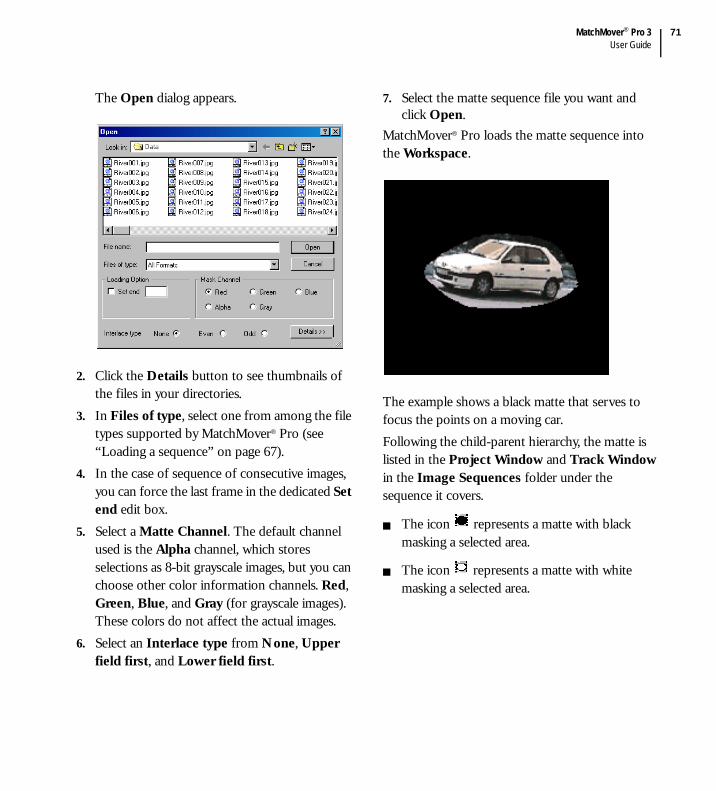
MatchMover® Pro 3User Guide
71
The Open dialog appears.
2. Click the Details button to see thumbnails of the files in your directories.
3. In Files of type, select one from among the file types supported by MatchMover® Pro (see “Loading a sequence” on page 67).
4. In the case of sequence of consecutive images, you can force the last frame in the dedicated Set end edit box.
5. Select a Matte Channel. The default channel used is the Alpha channel, which stores selections as 8-bit grayscale images, but you can choose other color information channels. Red, Green, Blue, and Gray (for grayscale images). These colors do not affect the actual images.
6. Select an Interlace type from None, Upper field first, and Lower field first.
7. Select the matte sequence file you want and click Open.
MatchMover® Pro loads the matte sequence into the Workspace.
The example shows a black matte that serves to focus the points on a moving car. Following the child-parent hierarchy, the matte is listed in the Project Window and Track Window in the Image Sequences folder under the sequence it covers.
The icon represents a matte with black masking a selected area.
The icon represents a matte with white masking a selected area.

Chapter 5User Guide
72
5.2.3.1. Displaying, hiding, and deleting mattesIf mattes are displayed, all the areas masked out are shown with the matte color and transparency in the 2D Mode. You can hide or show mattes by doing one of the following:
Select Display > Matte from the main menu.Right-click in the Workspace and select Display > Matte.
The checkmark beside the Matte option signifies that the matte is shown. Click on the option to deselect it and hide the matte. You will see the full video footage. To delete a matte, right-click on the matte in the Project Window and select Delete Matte from the contextual menu.
5.2.3.2. Setting the matte propertiesThe Parameters Window lists the matte properties.
The matte’s Label and File NameThe Number of Frames in the sequenceThe beginning and end Frames in the rangeThe Range of frames being usedThe Interlace attribute that you can set to None, Upper field first, and Lower field first.The displayed color and transparencyThe Group attributes.
You can also select the channel being used by the matte sequence. Red, Green, Blue, Alpha, and Gray (for grayscale images) channels. However, if a matte has only certain channels, the other channels are grayed out.Checking the option Inverted to invert the area that is masked. Optionally, right-click on the matte in the Project Window and select Invert to check the option.Each matte is displayed using alpha blending, with customizable transparency and color for each. Mattes also can be tagged as “Group” with a label, and are therefore used to design a coherent rigid mobile object. While autotracking, each object is handled separately, and a group of the specified label is created with its tracks in it, and is calibrated as a separate moving object.

MatchMover® Pro 3User Guide
73
5.2.3.3. Drawing mattes in MatchMover® ProMatchMover® Pro’s Matte Drawing Tool allows you to draw binary mattes to identify areas. These areas can be excluded from the automatic tracking process, or used to identify rigid moving objects. Mattes are the result of compositing one or several contours, which are closed, 2D polygons, defined using control points and animated over time. The Matte Drawing Tool allows you to place control points and, therefore, define contours. For any given frame, once you edit a contour, the frame is called a “keyframe” and the contours are interpolated in between keyframes.
A contour is active at the current frame if it effectively masks an area out. This is true for all frames between the first keyframe and the last keyframe, inclusive.A contour is inactive before its first keyframe and after its last keyframe.
You do not need to define a matte for each frame. Defining a matte for some keyframes is sufficient to exclude the required area from the tracking process. MatchMover® Pro interpolates the matte in the frames between the keyframes. You can apply several contours to the same image sequence, either at the same frame or at different frames.
The matte drawing workflow is described as follows:1. Create and close a contour.2. Create keyframes and interpolate the contour.3. Edit the contour, if necessary.4. Use several contours to mask areas of a
sequence.
Note: Both imported mattes and contours can be used at the same time.
5.2.3.4. Creating a new contourWhen you draw a contour, the last point that was added or edited is the active point. For an open curve, the active point must be the last point of the curve. The active point is highlighted red.To draw a new contour:1. Do one of the following:
Select Contour > New Contour.
Click on the New Contour icon in the 2D Tracking tab of the Main Toolbar.
MatchMover® Pro enters the Contour Drawing mode, creates a new empty contour
and selects it. The pointer changes to .
To exit the Contour Edition Mode, select any other element in the project (or press Esc).
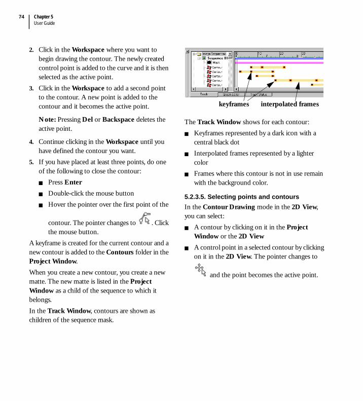
Chapter 5User Guide
74
2. Click in the Workspace where you want to begin drawing the contour. The newly created control point is added to the curve and it is then selected as the active point.
3. Click in the Workspace to add a second point to the contour. A new point is added to the contour and it becomes the active point.
Note: Pressing Del or Backspace deletes the active point.
4. Continue clicking in the Workspace until you have defined the contour you want.
5. If you have placed at least three points, do one of the following to close the contour:
Press EnterDouble-click the mouse buttonHover the pointer over the first point of the
contour. The pointer changes to . Click the mouse button.
A keyframe is created for the current contour and a new contour is added to the Contours folder in the Project Window.When you create a new contour, you create a new matte. The new matte is listed in the Project Window as a child of the sequence to which it belongs. In the Track Window, contours are shown as children of the sequence mask.
The Track Window shows for each contour:Keyframes represented by a dark icon with a central black dotInterpolated frames represented by a lighter colorFrames where this contour is not in use remain with the background color.
5.2.3.5. Selecting points and contoursIn the Contour Drawing mode in the 2D View, you can select:
A contour by clicking on it in the Project Window or the 2D ViewA control point in a selected contour by clicking on it in the 2D View. The pointer changes to
and the point becomes the active point.
keyframes interpolated frames

MatchMover® Pro 3User Guide
75
When you select a contour in the Contour Drawing mode, it is represented by a thick outline and control points.
Other contours in the selected frame are represented by thin outlines and control points.
If the selected contour is inactive for the current frame, it is represented by a dashed line.
Inactive contours that are not selected are not displayed.
Note: While you are working on contours, the resulting matte is not shown in the 2D View, only the outline is displayed, even if matte display is turned off.
5.2.3.6. Changing a contour’s properties The image below shows the contour’s Parameters window.

Chapter 5User Guide
76
To rename the contour, change the name of the contour in the Label text field in the Parameters Window. The matte’s name is updated in the Image Sequences folder in the Project Window.The read-only text field Control points displays the number of vertices or control points for the contour.Check the option Inverted to exclude the area outside the contour instead of excluding the one inside.Check the Group attributes to specify a rigid moving object and set its corresponding sub-folder name.Choose contour displayed color and use the slidebar to adjust the transparency.
5.2.3.7. Deleting a contourDo one of the following:1. Select a contour and either:
Select Contour > Delete.Right-click in the 2D View and select Delete Contour from the contextual menu.Press the Delete key.
2. Right-click on the contour in the Image Sequences folder in the Project Window or the Track Window and select Delete Contour from the contextual menu.
The selected contour is removed.
5.2.3.8. About keyframes and interpolating the contourA keyframe is created for each closed contour. When you change the current time, the contour shown in the Workspace depends on the content of the contour at this frame.
If this is a keyframe, the contour for this keyframe is displayed.If the contour is interpolated at this frame, the result of the interpolation is displayed.Otherwise, the curve for the closest keyframe will be displayed.
Editing the curve at the current frame creates a new keyframe at the current frame and interpolates it between the other keyframe from which it was copied.
5.2.3.9. Adding a keyframeTo add a keyframe, do one of the following:
Select Contour > Add Keyframe.Right-click in the 2D View and select Add Keyframe from the contextual menu.
MatchMover® Pro creates a keyframe for the selected contour at the current frame using either the interpolated curve, if any, or the displayed curve.If the new keyframe is between existing keyframes, then the interpolated curve is used. Otherwise a copy of the contour at the nearest keyframe is used. This ensures that the domain of definition of a contour is always an interval.
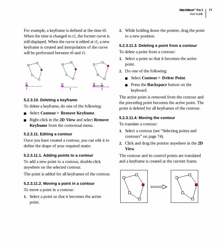
MatchMover® Pro 3User Guide
77
For example, a keyframe is defined at the time t0. When the time is changed to t1, the former curve is still displayed. When the curve is edited at t1, a new keyframe is created and interpolation of the curve will be performed between t0 and t1.
5.2.3.10. Deleting a keyframeTo delete a keyframe, do one of the following:
Select Contour > Remove Keyframe.Right-click in the 2D View and select Remove Keyframe from the contextual menu.
5.2.3.11. Editing a contourOnce you have created a contour, you can edit it to define the shape of your required matte.
5.2.3.11.1. Adding points to a contourTo add a new point to a contour, double-click anywhere on the selected contour.The point is added for all keyframes of the contour.
5.2.3.11.2. Moving a point in a contourTo move a point in a contour:1. Select a point so that it becomes the active
point.
2. While holding down the pointer, drag the point to a new position.
5.2.3.11.3. Deleting a point from a contourTo delete a point from a contour:1. Select a point so that it becomes the active
point.2. Do one of the following:
Select Contour > Delete Point.Press the Backspace button on the keyboard.
The active point is removed from the contour and the preceding point becomes the active point. The point is deleted for all keyframes of the contour.
5.2.3.11.4. Moving the contourTo translate a contour:1. Select a contour (see “Selecting points and
contours” on page 74).2. Click and drag the pointer anywhere in the 2D
View.The contour and its control points are translated and a keyframe is created at the current frame.
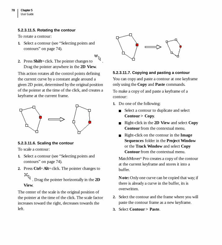
Chapter 5User Guide
78
5.2.3.11.5. Rotating the contourTo rotate a contour:1. Select a contour (see “Selecting points and
contours” on page 74).
2. Press Shift+click. The pointer changes to . Drag the pointer anywhere in the 2D View.
This action rotates all the control points defining the current curve by a constant angle around a given 2D point, determined by the original position of the pointer at the time of the click, and creates a keyframe at the current frame.
5.2.3.11.6. Scaling the contourTo scale a contour:1. Select a contour (see “Selecting points and
contours” on page 74).2. Press Ctrl+Alt+click. The pointer changes to
. Drag the pointer horizontally in the 2D View.
The center of the scale is the original position of the pointer at the time of the click. The scale factor increases toward the right, decreases towards the left.
5.2.3.11.7. Copying and pasting a contourYou can copy and paste a contour at one keyframe only using the Copy and Paste commands.To make a copy of and paste a keyframe of a contour:1. Do one of the following:
Select a contour to duplicate and select Contour > Copy.Right-click in the 2D View and select Copy Contour from the contextual menu.Right-click on the contour in the Image Sequences folder in the Project Window or the Track Window and select Copy Contour from the contextual menu.
MatchMover® Pro creates a copy of the contour at the current keyframe and stores it into a buffer.
Note: Only one curve can be copied that way; if there is already a curve in the buffer, its is overwritten.
2. Select the contour and the frame where you will paste the contour frame as a new keyframe.
3. Select Contour > Paste.
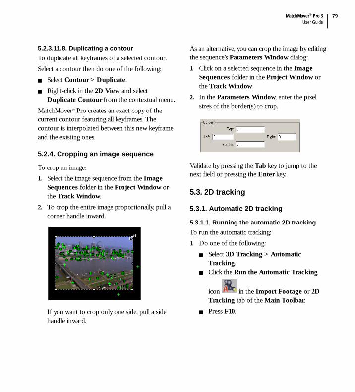
MatchMover® Pro 3User Guide
79
5.2.3.11.8. Duplicating a contourTo duplicate all keyframes of a selected contour.Select a contour then do one of the following:
Select Contour > Duplicate.Right-click in the 2D View and select Duplicate Contour from the contextual menu.
MatchMover® Pro creates an exact copy of the current contour featuring all keyframes. The contour is interpolated between this new keyframe and the existing ones.
5.2.4. Cropping an image sequence
To crop an image:1. Select the image sequence from the Image
Sequences folder in the Project Window or the Track Window.
2. To crop the entire image proportionally, pull a corner handle inward.
If you want to crop only one side, pull a side handle inward.
As an alternative, you can crop the image by editing the sequence’s Parameters Window dialog:1. Click on a selected sequence in the Image
Sequences folder in the Project Window or the Track Window.
2. In the Parameters Window, enter the pixel sizes of the border(s) to crop.
Validate by pressing the Tab key to jump to the next field or pressing the Enter key.
5.3. 2D tracking
5.3.1. Automatic 2D tracking
5.3.1.1. Running the automatic 2D trackingTo run the automatic tracking:1. Do one of the following:
Select 3D Tracking > Automatic Tracking.Click the Run the Automatic Tracking
icon in the Import Footage or 2D Tracking tab of the Main Toolbar. Press F10.

Chapter 5User Guide
80
A pop-up dialog appears, listing the steps in the automatic matchmoving process.
If checked, Clear Automatic Tracks clears previously generated automatic tracks,
which are indicated by red icons. All tracks that are either locked or manual (with no red icon) will remain. If you are starting a project from scratch, this step will do nothing.The next step, 2D Tracking, extracts relevant information from images within the video sequence as you would do manually (see “Supervised 2D tracking” on page 83). All tracks generated during this step are flagged “automatic.”In Camera Solving, the movement of the camera in 3D space and its (the camera’s) settings are calculated. For more details, see “Solving for the camera” on page 120.
2. From the drop-down list, choose either Grayscale for sequences or images with high contrast. If you choose Colors, the computation is slower, but more accurate than when you choose the Grayscale option. The option is stored in the 2D Tracking page of the User Preferences dialog.
Tip: Use the Colors option when your sequences contains motion blur or low-contrast images or sequences.
3. Now click Run to begin the matchmoving process. Colored indicators beside the option name show you the status of the process as well as the status of each step.
A gray button indicates a task that has not been started yet.A yellow button indicates a task in progress.A green button indicates a completed task.

MatchMover® Pro 3User Guide
81
5.3.1.2. Viewing the resultsUpon completion of the automatic tracking process, you will have:
A list of the automatically generated point
tracks, marked with an symbol, in the Point Tracks / Auto Tracks folder (and optionally, moving rigid object sub-folders, if any) in the Project Window and Track Window. Tracks are only generated in areas of the image that are not masked or cropped out. Each track is automatically named “Auto####,” where “####” represents the track number.
Note: If you right-click on any automatically-generated point in the Auto Tracks folder in the Project Window, the option Auto Track is checked in the contextual menu, indicating that the point was generated automatically. Similarly, the read-only text field Automatic is checked for the point track in the Parameters Window.
5.3.1.3. Differences with supervised trackingRunning the automatic tracking is an easy and robust way to track many points simultaneously. The process can be launched whenever needed, on the entire sequence or on a selected time range, on the entire image, or an selected areas only using masks. The automatic process is different from supervised tracking in the sense that as many tracks are handled at the same time, 3D coherency is used while tracking.
Also, when supervised tracks are present before launching the automatic process, they are used in the 3D coherency checking.The results are different from the kind of tracks you will have when using the supervised tracking, as in this case, each track is handled individually.As automatic tracking may lead to huge number of tracks, an automatic track is not guaranteed to be used in the solving process. An algorithm that automatically selects the best automatic tracks to fit the computation in memory is launched before the solving. To remove the automatic flag of a track, simply edit it, or right-click and deselect the automatic option in the contextual menu. This way you’re sure it will always be fed into the engine.Apart from this difference, automatic and supervised tracks are handled by the same tools.
5.3.2. Refining the results
If you are satisfied with the results of the automatic tracking process, you can export your project at this point. Otherwise, you may want to edit the 2D tracks. You can do so by:
Adding tracks (see “Creating a new track” on page 83).Deleting unnecessary or unwanted tracks (see “Deleting tracks” on page 85).Cleaning up the 2D tracks (see “Cleaning up tracks” on page 82).
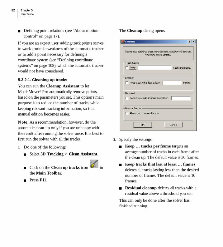
Chapter 5User Guide
82
Defining point relations (see “About motion control” on page 17).
If you are an expert user, adding track points serves to work around a weakness of the automatic tracker or to add a point necessary for defining a coordinate system (see “Defining coordinate systems” on page 108), which the automatic tracker would not have considered.
5.3.2.1. Cleaning up tracksYou can run the Cleanup Assistant to let MatchMover® Pro automatically remove points, based on the parameters you set. This option’s main purpose is to reduce the number of tracks, while keeping relevant tracking information, so that manual edition becomes easier.
Note: As a recommendation, however, do the automatic clean-up only if you are unhappy with the result after running the solver once. It is best to first run the solver with all the tracks.
1. Do one of the following:Select 3D Tracking > Clean Assistant.
Click on the Clean up tracks icon in the Main Toolbar.Press F11.
The Cleanup dialog opens.
2. Specify the settings.Keep … tracks per frame targets an average number of tracks in each frame after the clean up. The default value is 30 frames.Keep tracks that last at least … frames deletes all tracks lasting less than the desired number of frames. The default value is 10 frames.Residual cleanup deletes all tracks with a residual value above a threshold you set.
This can only be done after the solver has finished running.

MatchMover® Pro 3User Guide
83
3. If you do not want to delete manually added tracks, select the option to Always keep manual tracks.
For example, if a track satisfies at least one condition, it will be kept. For instance if you set the length > 10 and residual < 0.8, then a track lasting six frames with residual 0.4 will be kept because of the second filter.
Tip: The Automatic Cleanup option of the previous version of MatchMover® Pro is roughly equivalent to keeping 40 tracks per frame.
5.3.3. Supervised 2D tracking
MatchMover® Pro allows manual editing of track points. In addition, advanced users may prefer to manually add tracks before running the automatic tracking process to strengthen the result, or after, to refine the result.
5.3.3.1. Creating a new trackTo create a new track.1. Do one of the following:
Select 2D Tracking > New Track.
Click on the New Track icon in the 2D Tracking tab of the Main Toolbar.Right-click in the 2D View or in the Point Tracks folder in the Project Window or the Track Window and select New Track from the contextual menu.
MatchMover® Pro creates an item in the Point Tracks sub folder in the Project Window and
the pointer changes to in the Workspace. Whenever the pointer has this appearance, you are in the New Track Creation mode.
2. Position the pointer where you want to create a key for this track and click.
See “Magnifier Window” on page 59 for the Magnifier configuration.
Note: You can simply create tracks in the same way in the 2D or 3D mode using Shift+right-click on the background image plane.
When you add a track, the following icons appear in the Project Window indicating the track status.
Icon Description
Indicates a point that is not used for calibration and not reconstructed in 3D
Indicates a point that is not used for calibration but is reconstructed in 3D
Indicates a point that is used for calibration and not reconstructed in 3D
Indicates a point that is used for calibration and is reconstructed in 3D

Chapter 5User Guide
84
A track that has been reconstructed after the last calibration, and therefore not used to compute it, is shown with a little star on the upper left.In the Parameters Window or if you right-click on any point in the Point Tracks folder in the Project Window or the Track Window, the following options are checked by default in the contextual menu and correspond to the icons above table.
Use for 3D Solving, indicating that the point is to be used in the solving process.Reconstructed in 3D, indicating that the point will be reconstructed in 3D.
You can access the detailed 3D information of a track in the 3D tab of its Parameters Window.The dialog shows read-only fields:
The point coordinates, X, Y, and Z, calculated by the camera solving process.The Residual at time, which is the difference in pixels between the 2D point position and the position obtained by viewing the reconstructed 3D point through the calculated camera at the current time.The Average Residual, which shows the average difference in pixels for all the frames.
For example, you want to track a table corner through an image sequence. In image 0, press Shift+right-click on the table corner. MatchMover® Pro creates the “Track 0” and an intermediate key. The tracker uses this key point to remain on the point track during the tracking process. Now, you can launch the tracker.The Relations tab just shows the list of relations involving this track. Double-click on one to select it.
Note: For 2D configuration, see “Setting the parameters of a single key point” on page 91 and “Color Tracking” on page 92. For 3D survey configuration, see “Defining survey points and object mapping” on page 114.

MatchMover® Pro 3User Guide
85
5.3.3.2. Selecting tracksClick on a track (either the cross, the pattern, the point or the 3D helper depending on your current view and settings) to select it.To select several points, do any of the following:
In the Workspace, hold the Shift key and click the points in the image one by one.In the Workspace, click on the image and drag the pointer to contain certain points in a selection Rectangle or click several points to define a polygon Contour (2D mode only) then release the mouse button. The selection mode is specified in the Track Selection Display drop-down list in the Preferences > Display dialog. All tracks with points inside the rectangle or contour are selected.
To add to the selection, press the Shift key. To deselect the points, click on any empty area in the image or press Esc.For a sequential selection, in the folder Point Tracks in the Project Window, click the first point, press and hold the Shift key, and click the last point drag the rubber rectangle to select points.
For a non-sequential selection, in the folder Point Tracks in the Project Window, hold the Ctrl key and click the points one by one.
Note: The currently selected track or a track multiselection can be inverted by right-clicking in the Project Window and selecting Invert Selection from the contextual menu.
5.3.3.3. Deleting tracksTo delete tracks, do one of the following:
Select the track(s) that you want to delete.Select Edit > Delete.Press the Delete key.
Right-click on the track(s) in the Project Window or the Track Window and select Delete Track.
5.3.3.4. Merging tracksWhen 2D features of the scene move out of the view then back in or are occulted by objects in motion causing the tracker to misinterpret them as distinct points, you can merge the keys from several tracks into one.1. Select at least two track points to merge. 2. Do one of the following:
Select 2D Tracking > Merge Tracks.Right-click in the 2D View or the Point Tracks folder in the Project Window or the Track Window and select Merge Tracks from the contextual menu.
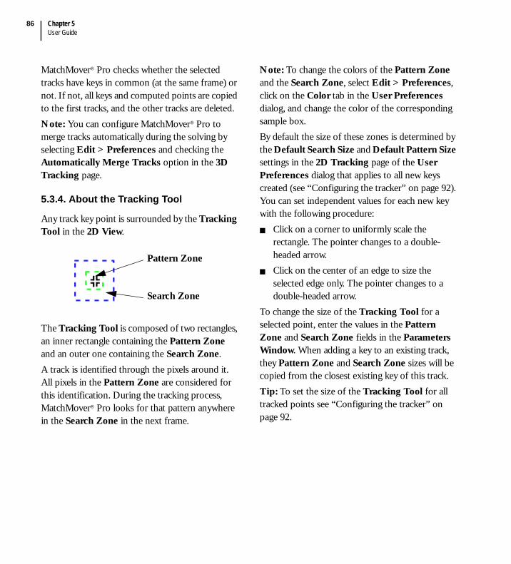
Chapter 5User Guide
86
MatchMover® Pro checks whether the selected tracks have keys in common (at the same frame) or not. If not, all keys and computed points are copied to the first tracks, and the other tracks are deleted.Note: You can configure MatchMover® Pro to merge tracks automatically during the solving by selecting Edit > Preferences and checking the Automatically Merge Tracks option in the 3D Tracking page.
5.3.4. About the Tracking Tool
Any track key point is surrounded by the Tracking Tool in the 2D View.
The Tracking Tool is composed of two rectangles, an inner rectangle containing the Pattern Zone and an outer one containing the Search Zone.A track is identified through the pixels around it. All pixels in the Pattern Zone are considered for this identification. During the tracking process, MatchMover® Pro looks for that pattern anywhere in the Search Zone in the next frame.
Note: To change the colors of the Pattern Zone and the Search Zone, select Edit > Preferences, click on the Color tab in the User Preferences dialog, and change the color of the corresponding sample box.By default the size of these zones is determined by the Default Search Size and Default Pattern Size settings in the 2D Tracking page of the User Preferences dialog that applies to all new keys created (see “Configuring the tracker” on page 92). You can set independent values for each new key with the following procedure:
Click on a corner to uniformly scale the rectangle. The pointer changes to a double-headed arrow.Click on the center of an edge to size the selected edge only. The pointer changes to a double-headed arrow.
To change the size of the Tracking Tool for a selected point, enter the values in the Pattern Zone and Search Zone fields in the Parameters Window. When adding a key to an existing track, they Pattern Zone and Search Zone sizes will be copied from the closest existing key of this track.Tip: To set the size of the Tracking Tool for all tracked points see “Configuring the tracker” on page 92.
Pattern Zone
Search Zone
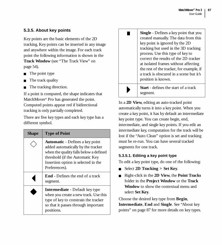
MatchMover® Pro 3User Guide
87
5.3.5. About key points
Key points are the basic elements of the 2D tracking. Key points can be inserted in any image and anywhere within the image. For each track point the following information is shown in the Track Window (see “The Track View” on page 54).
The point typeThe track qualityThe tracking direction.
If a point is computed, the shape indicates that MatchMover® Pro has generated the point. Computed points appear red if bidirectional tracking is only partially completed.There are five key types and each key type has a different symbol.
In a 2D View, editing an auto-tracked point automatically turns it into a key point. When you create a key point, it has by default an intermediate key point type. You can create begin, end, intermediate, and single key points. If you edit an intermediate key, computation for the track will be lost if the “Auto Clean” option is set and tracking must be re-run. You can have several tracked segments for one track.
5.3.5.1. Editing a key point typeTo edit a key point type, do one of the following:
Select 2D Tracking > Set Key.Right-click in the 2D View, the Point Tracks folder in the Project Window or the Track Window to show the contextual menu and select Set Key.
Choose the desired key type from Begin, Intermediate, End and Single. See “About key points” on page 87 for more details on key types.
Shape Type of Point
Automatic - Defines a key point added automatically by the tracker when the quality falls below a defined threshold (if the Automatic Key Insertion option is selected in the Preferences).
End - Defines the end of a track segment.
Intermediate - Default key type when you create a new track. Use this type of key to constrain the tracker so that it passes through important positions.
Single - Defines a key point that you created manually. The data from this key point is ignored by the 2D tracking but used in the 3D tracking process. Use this type of key to correct the results of the 2D tracker at isolated frames without affecting the rest of the tracker, for example, if a track is obscured in a scene but it’s position is known.
Start - defines the start of a track segment.

Chapter 5User Guide
88
Notice that the key symbol changes (in the Track Window), to show the new status of the key.
5.3.5.2. Inserting a new key point in a trackSelect a track. Click and hold in the 2D View where you want to place the new key. By default MatchMover® Pro zooms in on the area using a pop-up magnifier.
Note: You can replace the pop-up magnifier with the Magnifier Window to help you in placing a key point, see “Magnifier Window” on page 59.
MatchMover® Pro places the key. The center of the key point is marked with a cross that is surrounded by two boxes. This is the Tracking Tool (see “About the Tracking Tool” on page 86 for more details). The key type symbol and its label are also displayed.
Tip: Repeat the procedure for other tracks in the same frame or for other keys for the same track in different frames. If you want to place other key points for the same track, you can use the Auto Key Match function.
In editing keys while a 2D View is in focus, you can use the arrow keys to move the current key. You set the number of pixels for each hit in the Nudge step box in Edit > Preferences > 2D Tracking (see “Configuring the tracker” on page 92). The value can be less than one pixel. If the edited point was not a key, it is automatically turned into one.
Tip: pressing shift with an arrow key will multiply the nudge step by 10.
5.3.5.3. Moving a key point1. Select the key point you want to move. The
pointer changes to .2. Drag the pointer to the new position and
release.
Note: If Auto Clean is enabled, this action deletes the 2D computed points that have been created from this key. To recompute these points, you have to rerun the tracking process. To enable or disable Auto Clean, select Edit > Preferences > 2D Tracking and click the corresponding box.
5.3.5.4. Deleting a key1. Select a track then a frame if none is selected.2. Do one of the following:
Select 2D Tracking > Clear Keys.Right-click in the 2D View or the Point Tracks folder in the Project Window or the Track Window to show the contextual menu and select Clear Keys.
If you have not created a time range, MatchMover® Pro deletes the key at the current time. If you have created a time range, MatchMover® Pro deletes all keys within the time range.
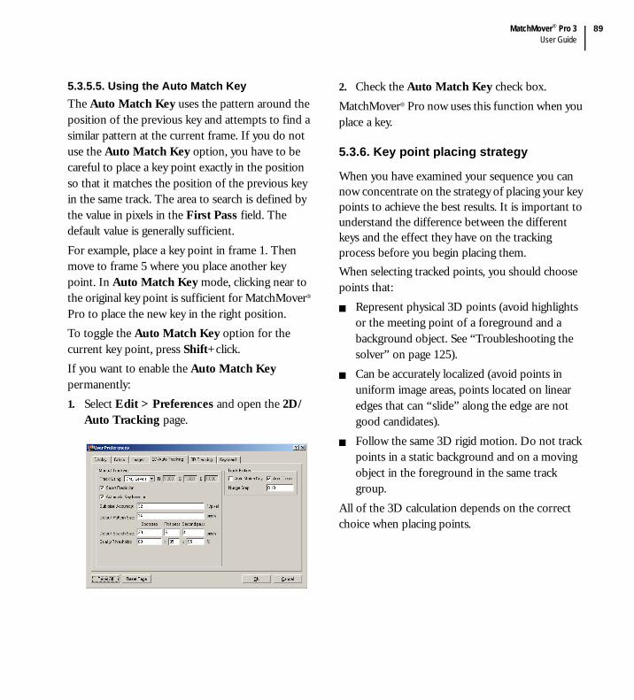
MatchMover® Pro 3User Guide
89
5.3.5.5. Using the Auto Match KeyThe Auto Match Key uses the pattern around the position of the previous key and attempts to find a similar pattern at the current frame. If you do not use the Auto Match Key option, you have to be careful to place a key point exactly in the position so that it matches the position of the previous key in the same track. The area to search is defined by the value in pixels in the First Pass field. The default value is generally sufficient. For example, place a key point in frame 1. Then move to frame 5 where you place another key point. In Auto Match Key mode, clicking near to the original key point is sufficient for MatchMover® Pro to place the new key in the right position.To toggle the Auto Match Key option for the current key point, press Shift+click.If you want to enable the Auto Match Key permanently:1. Select Edit > Preferences and open the 2D/
Auto Tracking page.
2. Check the Auto Match Key check box.MatchMover® Pro now uses this function when you place a key.
5.3.6. Key point placing strategy
When you have examined your sequence you can now concentrate on the strategy of placing your key points to achieve the best results. It is important to understand the difference between the different keys and the effect they have on the tracking process before you begin placing them.When selecting tracked points, you should choose points that:
Represent physical 3D points (avoid highlights or the meeting point of a foreground and a background object. See “Troubleshooting the solver” on page 125).Can be accurately localized (avoid points in uniform image areas, points located on linear edges that can “slide” along the edge are not good candidates).Follow the same 3D rigid motion. Do not track points in a static background and on a moving object in the foreground in the same track group.
All of the 3D calculation depends on the correct choice when placing points.

Chapter 5User Guide
90
Tip: Before creating your key points within the image sequence, review the sequence and plan the key point positioning. This aids the tracker calculations and saves you time and effort in the later stages.
Scatter - Place the key points over the widest possible area trying to cover the 3D volume. Concentrate on areas where you want to put a 3D object.Balance - As you move through the sequence some points may leave the frame and other points may enter the frame. Therefore try to keep a balance of the number of points within each frame and avoid a lot of points leaving or entering at the same time.Depth - Place key points in the background and the foreground of your sequence to enable depth calculations.
5.3.6.1. ExamplesImage masking - You want to track a point from image 1 to image 20. You know that in images 12 to 15 there is a partial masking of the point. You place a Begin key in image 1 and an end key in image 20. For the images 12 to 15, you may be able to place single keys. The tracker ignores these keys and this part of the sequence. Therefore the tracker tracks from image 1 to image 12 then ‘jumps’ to image 16. However, the 3D tracker uses the single key points in the same way as other points.
Intermediate keys - You want to track a point from image 1 to 20. However, the point in image 1 and in image 20 is very blurred so you cannot place a begin key or end key. In image 10 the point is clear so you place an Intermediate key and launch a forward track to image 20 and a backward track to image 1. By doing this you succeed in tracking the point throughout the entire sequence despite the blur.Variable Zoom - If you track a feature with an image size that changes drastically (large motion or zoom), it is better to place a key in a frame where the resolution is high and start tracking from this key towards frames where the feature appears smaller.
5.3.7. Setting key point parameters
By default each key point has a pattern size, search zone and quality threshold, as defined in 2D Tracking page of the User Preferences dialog (see “Configuring the tracker” on page 92). These parameters are global and apply to all key points, however it is possible to set the parameters for each key point separately. In most cases the default values are sufficient to complete a successful track, but you may want to set them.
MatchMover® Pro 3User Guide
91
5.3.7.1. Setting the parameters of a single key pointTo set the parameters of a single key point:1. Select the point to edit.2. In the Parameters Window, the Current time
text field shows the current time. Refer to the following list for parameters details:
The horizontal point position X in pixels in the image (if the point is a key, you can modify its position. The origin is the upper left corner of the image).The vertical point position Y in pixels in the image.Status shows the type of key. Select a new key type from Begin, End, Intermediate, and Single from the drop-down list. Threshold is the minimum accuracy of the similarity between two pixels. A value too low causes the tracker to match any pixels. A value too high causes the tracker to stop or to place too many automatic keys.Pattern Zone is the area to search for in the adjacent image. You can use different values for the different sides. For example, if you track a point within an area of uniform color, the tracker may have problems to follow the point. Increase the template area to include pixels of a different brightness to eliminate this problem.
Search Zone is the area in which to search, in the adjacent image. You can use different values for the different sides. If you see that the point moves a lot through the sequence, make the search area larger, remembering that a larger search size decreases the tracking speed.
The tracker uses these parameters to find the corresponding point in the adjacent image and track the point and the information is updated if you change the current time.
Note: If the selected point is not a key point, but has been calculated by the tracking process, then you can only read the track point information in the 2D page.
Parameters at time shows the current time.X shows the horizontal pixel position of the point in the image. The origin is the upper left corner of the image.Y shows the vertical pixel position of the point in the image. The origin is the upper left corner of the image.Tracking Score shows the estimated precision quality of the tracking.Status shows the type of tracking used to calculate this point. the status can be Forward, Backward or Bidirectional.

Chapter 5User Guide
92
5.3.7.2. Color TrackingAll key points have a separate color tracking setting. For example, a red cross on green background may ignore blue channel.
Gray. Track using luminance information (an average of the R,G,B colors). This is the default option.Color. Track using all color components independently.Coeff. Track using a coefficient for each color channel. For example, when a color seems to be too “noisy”, just lower its coefficient. If the coefficient is 0, then the color is ignored.Auto. Track using a coefficient for each color channel, but coefficient is computed automatically. MatchMover® Pro analyzes the image to find the best coefficient.
5.3.8. Configuring the tracker
Before launching the tracker you can configure the parameters to aid the tracking process. When you have a sequence with particular characteristics, such as zoom or rapid movement causing blur, you set the tracker’s parameters to aid the tracking process.Select Edit > Preferences and select the 2D/Auto Tracking page.
Choose the desired options. By default the options Gray Levels, Smart Prediction and Automatic Key Insertion are selected. These options apply to all key points.
Track using - Use Color where the contrast between two colors is low. For high-contrast colors, use Gray Levels. The Gray Levels option is faster, but less accurate than the Color option. See“Color Tracking” on page 92 for other options.Auto Match Key - Toggles the use of automatic key placing. This decreases the possibility of error by placing the key using the position of the neighboring key.Auto Clean - toggles the automatic removal of all tracked points when editing the originator key. It is enabled by default.

MatchMover® Pro 3User Guide
93
Smart Prediction - predicts the position of a point in the successive image and reduces the tracking time by a factor of 10. Smart Prediction works in smooth sequences so if you have a “shaky” camera sequence toggle the Smart Prediction option to off. If there is a smooth camera movement, use the option.Nudge step - sets the number of pixels for each arrow-key press when editing keys. The value can be less than one pixel.Automatic Key Insertion - places automatic keys when the quality falls below a certain threshold caused by factors such as camera zoom (the pattern followed by the tracker changes size and resembles less and less the original pattern, causing the quality to decrease). If you do not use Automatic Key Insertion under these circumstances the tracker halts. You may notice that in some situations the position of an automatic key deviates from the point to track, if this is the case toggle Automatic Key Insertion to off.
Tip: You want to track a point from image 20 to image 40. If you know that within this sequence there is a zoom, use Automatic key insertion. By using the Automatic key insertion option the tracker is able to follow the point, despite the zoom.
The other options in the User Preferences dialog refer to the default settings of the key points. Any changes made here affect all new key points. The settings for current key points do not change.
To change values for a single key point, use the Parameters Window (see “Setting the parameters of a single key point” on page 91).
Default Pattern Size defines the area to search for in the adjacent image. The default value of 14 means that the Pattern Size is 7 pixels to the left of the point and 7 pixels to the right.Default Search Size
Bootstrap - Defines the search area in pixels used by all the key points when Smart Prediction is not used. Increase this value if you find that the pixel motion of the point you are tracking moves substantially. If Smart Prediction is used the Bootstrap value is used up to the point where the prediction process starts.First Pass - Defines the search area in pixels when Smart Prediction is selected. The tracker starts with the Bootstrap value then changes to the First Pass value when the Smart Prediction process starts. When the sequence is not as smooth as you would like and you still want to use Smart Prediction, increase the First Pass value.Second Pass - Defines the search area in pixels and is only used in a bi-directional tracking. If you have already tracked in one direction, the tracker uses this value for the opposite direction track. The tracker uses the results from the direction already tracked and therefore the search is more localized, the search area is smaller and the tracking process is faster.
Chapter 5User Guide
94
Sub-pixel Accuracy - Defines the search precision. For example, a value of 8 means the maximum search distance of the pixel match is 1/8th of a pixel. The tracking process is slightly longer when there is a high accuracy value.Quality Thresholds - Stop defines the minimum quality value. There are two possible situations. If Automatic key insertion is not selected and the quality falls below this value, the tracker stops. If Automatic key insertion is selected and the quality falls below this value an automatic key is inserted.For display purposes the Poor and Good values determine the on-screen appearance of the points in the Track Window. They have no effect on the tracking process itself. A quality value between the Stop and Poor values is shown as red. A quality value between the Poor and Good values is shown as yellow. A quality value above the Good value is shown as green.
5.3.9. Running the tracker
By default when you run the tracker the whole of your sequence is tracked (as defined by the key types). If you want to track points for a subset of your sequence you must create a time range.You can run the tracker in three ways.
A forward trackA backward trackA bi-directional track
The tracker stops when.It reaches the beginning or end of the sequence or time range.The match falls below the quality set in the tracking parameters box.It reaches a Begin or End key point.The point is about to leave the image.
To check the quality of the tracking you can zoom on the image to view the pixels. Do one of the following then zoom on the track:
Select View > Lock On Track.Right-click in the 2D View and select Lock On Track from the contextual menu.
Click on the Lock On Track icon in the Display Toolbar.
5.3.9.1. About the tracking monitorWhen you run the 2D tracking process, the Track Monitor appears in a toolbox window. It shows a zoomed view of the point being tracked through the sequence.
5.3.9.2. Running the tracker forward or backwardYou can launch the tracking process in a forward or backward direction. Only one key point is necessary to track either forward or backward, but it must be either a begin key or an intermediate key. Only one point can be tracked at a time. When more than one track is selected, the tracking function is disabled.

MatchMover® Pro 3User Guide
95
To run the tracker forward or backward, either:Select 2D Tracking > Track Forward or Track Backward.Right-click on a track in the 2D View, the Point Tracks folder in the Project Window or the Track Window to open the contextual menu and select Track Forward or Track Backward.Click on the Run/Stop Track Forward icon
or Run/Stop Track Backward icon
in the 2D Tracking tab in the Main Toolbar.
MatchMover® Pro launches the 2D tracker. Notice that by default the Tracking Monitor opens showing the point being tracked through the image sequence. A colored line in the Track View shows the track as it is tracked.
Tip: To obtain the best results, when you have placed two key points in a sequence, use the option Bidirectional.
5.3.9.3. Running the tracker in bidirectional modeThis option launches the tracking process in a forward and backward direction. There must be at least two key points enclosing the segment or sequence to track. Use this option when there is some deviation of the point through the track sequence.
By blending the two trajections produced by forward and backward tracking, MatchMover® Pro guarantees that the final point track has a smooth trajectory that passes exactly through the two enclosing key points. To run the tracker bidirectional, do one of the following:
Select 2D Tracking > Track Bidirectional.Right-click on a track in the 2D View, the Point Tracks folder in the Project Window or the Track Window to open the contextual menu and select Track Bidirectional.Click on the Run/Stop Track Bidirectional
icon in the 2D Tracking tab in the Main Toolbar.
MatchMover® Pro launches the 2D tracker.
5.3.10. Computed 2D points
The tracker automatically creates and places computed 2D points, using information from the key points, in the sequence, that are used in the camera solving process. The type of computed point generated depends on the type of tracking process that you run to create them.
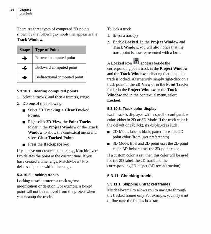
Chapter 5User Guide
96
There are three types of computed 2D points shown by the following symbols that appear in the Track Window.
5.3.10.1. Clearing computed points1. Select a track(s) and then a frame(s) range.2. Do one of the following:
Select 2D Tracking > Clear Tracked Points.Right-click 2D View, the Point Tracks folder in the Project Window or the Track Window to show the contextual menu and select Clear Tracked Points.Press the Backspace key.
If you have not created a time range, MatchMover® Pro deletes the point at the current time. If you have created a time range, MatchMover® Pro deletes all points within the range.
5.3.10.2. Locking tracksLocking a track protects a track against modification or deletion. For example, a locked point will not be removed from the project when you cleanup the tracks.
To lock a track.1. Select a track(s). 2. Enable Locked. In the Project Window and
Track Window, you will also notice that the track point is now represented with a lock.
A Locked icon appears beside the corresponding point track in the Project Window and the Track Window indicating that the point track is locked. Alternatively, simply right-click on a track point in the 2D View or in the Point Tracks folder in the Project Window or the Track Window and in the contextual menu, select Locked.
5.3.10.3. Track color displayEach track is displayed with a specific configurable color, either in 2D or 3D Mode. If the track color is the default one (black), it’s displayed as such.
2D Mode. label is black, pattern uses the 2D point color (from user preferences)3D Mode. label and 2D point uses the 2D point color. 3D helpers uses the 3D point color.
If a custom color is set, then this color will be used for the 2D label, the 2D track and the corresponding 3D helper (3D reconstruction).
5.3.11. Checking tracks
5.3.11.1. Skipping untracked framesMatchMover® Pro allows you to navigate through the tracked frames only. For example, you may want to fine-tune the frames in a track.
Shape Type of Point
Forward computed point
Backward computed point
Bi-directional computed point

MatchMover® Pro 3User Guide
97
By selecting View > Skip Untracked or clicking
on the icon in the Display toolbar, any navigation command (except direct mouse click or a user input) skips the frames where the selected track is not defined. The icon appears next to the Lock on Track icon.
5.3.11.2. Skipping unsolved tracksIf you are working only on a part of your sequence, for example, you loaded a 100 frames sequence, but the frames 30 to 60 are not important, you can set those frames to “Do not solve” (see “Setting frames to solve” on page 121) and select View > Skip Unsolved to activate the option. After calibration, any navigation command (except direct mouse click or user input) skips the frames that are not solved.
5.3.11.3. The Magnifier’s fast refreshWhen the Magnifier window is locked by clicking on the padlock to the right of the zoom bar, you can click on a track and play the sequence to check the track’s path (see “Magnifier Window” on page 59 for more details). Note that in this case, and if the format allowed it, only the Magnifier displayed area is loaded for a faster refresh
5.3.12. Troubleshooting the tracker
If the tracker fails, it is often because the aspect of the tracked pattern has changed significantly between the reference frame (the track start frame) and the current frame. If the solver has already been launched, you can verify the distance in pixels between a 2D point and the projection of a 3D point on the camera in the 2D View or in the Survey View (see “Examining the computation quality in the Survey Window” on page 124). You can examine the residuals for all the points and frames. Sort them by frame and check if any points have a high residual value. If so, it is probably because the point has been poorly located by the 2D tracker. If a frame has a high error, viewed in the Frame mode, this may be due to the bad positioning of a 2D computed point within the frame.
unsolvedframes
Chapter 5User Guide
98
By examining the errors on the points in the Points mode, it is possible to find the computed 2D point responsible for the high error. It is then useful to restart the tracker from an intermediate frame (insert an intermediate key), where the tracked position is correct, and the aspect is more similar to the current frame.You can also check the track path for bumps. If the track path is jagged, it means that either the camera follows a jerky motion, or that the point suddenly drifted during tracking. In this case, you should return at the time the track jumped, and correct it by creating a new key at the appropriate coordinates and resuming tracking.Another potential cause for the tracker to stop is when the point image motion is so fast that the search area of the tracker becomes smaller than the point displacement between two consecutive frames. If this is the case enlarge the search area and re-run the tracker from the last correct frame, then reduce the search area to a normal size.When a point that is being tracked starts to leave the image, MatchMover® Pro shows a warning message and the 2D tracker stops. When the quality of the tracking falls below the defined threshold a warning message appears and the tracking stops.Tip: Do not forget that in Smart Prediction mode, the search area defined with the tracker tool is only used in the first and the second frames, then the size used is the one defined by First Pass in the 2D Tracking page of the User Preferences dialog.
5.3.13. Groups attributes
To make complex supervised tracking a little easier, related tracks can be grouped together The group hierarchy will be exported and should be the same in the final 3D package.Each group has the same set of attributes as a track. The group has a label, which is the name of the item displayed in the Project Tree. All other attributes reflect the tracks stored in this group.
An unchecked option means that none of the tracks have this attribute.A checked option means that all of the tracks have this attribute.A dimmed option means that all of the tracks do not share the same value for this attribute.
By simply setting a group attribute, you apply the attribute to all the tracks in the group.Each group also has the “mobile” rigid object attributes (See “Moving objects” on page 99 for details).In addition, the group Parameters window shows the statistics of all its tracks. number of tracks, shortest, longest and average length. This is a good measure of the quality of an automatic process that generated a huge number of tracks. A good average length is usually synonymous of robust tracking.
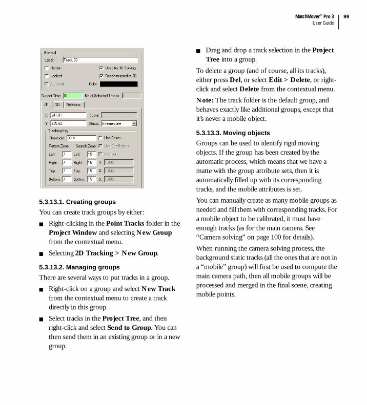
MatchMover® Pro 3User Guide
99
5.3.13.1. Creating groupsYou can create track groups by either:
Right-clicking in the Point Tracks folder in the Project Window and selecting New Group from the contextual menu.Selecting 2D Tracking > New Group.
5.3.13.2. Managing groupsThere are several ways to put tracks in a group.
Right-click on a group and select New Track from the contextual menu to create a track directly in this group.Select tracks in the Project Tree, and then right-click and select Send to Group. You can then send them in an existing group or in a new group.
Drag and drop a track selection in the Project Tree into a group.
To delete a group (and of course, all its tracks), either press Del, or select Edit > Delete, or right-click and select Delete from the contextual menu.Note: The track folder is the default group, and behaves exactly like additional groups, except that it’s never a mobile object.
5.3.13.3. Moving objectsGroups can be used to identify rigid moving objects. If the group has been created by the automatic process, which means that we have a matte with the group attribute sets, then it is automatically filled up with its corresponding tracks, and the mobile attributes is set.You can manually create as many mobile groups as needed and fill them with corresponding tracks. For a mobile object to be calibrated, it must have enough tracks (as for the main camera. See “Camera solving” on page 100 for details).When running the camera solving process, the background static tracks (all the ones that are not in a “mobile” group) will first be used to compute the main camera path, then all mobile groups will be processed and merged in the final scene, creating mobile points.

Chapter 5User Guide
100
As it is not possible to recover the scale between a mobile object and the background with a single camera, each group has a scale attribute that can be tuned directly in the group parameter’s corresponding edit box or by using the slider.
5.4. Camera solving
5.4.1. About keyframes
5.4.1.1. KeyframesKeyframes are specific frames for which the system first computes the camera parameters and 3D points using a powerful optimization process. Once keyframes and 3D points are computed, the system computes the intermediate frames by first interpolating between the keyframes, as in a standard animation package, then refining the camera parameters using the estimated 3D point information.MatchMover® Pro chooses automatically the keyframes to compute using the following criteria:
If the focal length is known, at least four 3D points are needed.If the focal length is unknown, at least six 3D points are needed. These points should not all lie on the same plane.
In most situations the keyframes chosen by MatchMover® Pro are sufficient, however in some cases (e.g. where there is jagged camera motion), it can be useful to position the keyframes manually. By default, keyframes, and indeed reference frames (see “Reference frames” on page 100), are chosen automatically. The number of keyframes is determined by the keyframe Step value and Maximum keyframes value. The keyframe Step value is the maximum number of frames between each keyframe. A low step value gives a higher accuracy, but computation is slower.The Maximum keyframes value determines the highest number of non-automatic keyframes allowed in a sequence. This value is only an indication, as the number of keyframes generated may be larger, especially in shots where a large number of points enter or leave the image.
Tip: Use enough keyframes to “cover” all the tracks, but bear in mind that too many keyframes slow the solving process. If there is a very smooth camera movement, very few keyframes are needed. keyframes should cover the movement in a sequence.
5.4.1.2. Reference framesReference frames are 2 specific keyframes that will be used to bootstrap the camera solving. They should therefore be rock-solid ones with good parallax. MatchMover® Pro chooses the reference frames automatically when you run the 3D tracker.

MatchMover® Pro 3User Guide
101
The data from 2D tracking is used to choose them, therefore if you change the data (e.g., you create a new point track), MatchMover® Pro may automatically chooses two new reference frames.MatchMover® Pro examines the image sequence and compares frames using two methods.Method 1. Where all the intrinsic parameters are known (through camera information and constraints), it checks that there are either:
At least four 3D points with known coordinates are common to two frames.At least seven points (of potentially unknown coordinates) are common to two frames.
Method 2. Where all the parameters are unknown (except nonlinear distortion, which must have an approximately value), it checks that there are at least six known 3D points between two frames.Ideally, they should include views of the same scene from a different position, which induces parallax between the images.The automatically generated reference frames, if not locked, are recomputed when you select 3DTracking > Solve for Camera (F9) or when you use 3D tracking > Select keyframes. They are locked either when the user edited them,
or when the lock icon at the right end of the Track View Graded Ruler graduation window is toggled. When locked, all the keys and references
frames are greyed, , otherwise they are highlighted in yellow, .
Note: If MatchMover® Pro cannot initialize the two reference frames, it warns you that there is not sufficient data to run the camera tracker. In this case, you have to provide added information by creating extra point tracks in the two frames or by defining 3D point coordinates using relations, where possible.
5.4.1.3. Changing the keyframe default settings1. Select Edit > Preferences and open the 3D
Tracking page.
2. Enter the keyframe Step value. A step of approximately 15-20 keyframes is generally a good trade-off between computation speed and accuracy.
3. Enter the Maximum keyframes. This value allows you to limit the calculation time regardless of the sequence size.
See “About keyframes” on page 100 for details.

Chapter 5User Guide
102
5.4.1.4. Selecting reference and keyframesAfter the 2D tracking process is complete, do one of the following:
Select 3D Tracking > Select keyframes.Right-click on the Image Sequences folder in the Project Window or in the Track Window and select Select keyframes from the contextual menu.
Note that if the keyframes are not locked (see “Reference frames” on page 100 for details), this step is automatically launched when running the solver.Once all the required keyframes are selected, user settings are applied to fill the gaps, with the non-automatic keyframes.At this point you can run the camera solving process using the reference and keyframes chosen by MatchMover® Pro, or you can choose your own by manually editing them. If you make any manual changes and want to return to automatic initialization, just click on the lock
icon or relaunch the Select keyframes command. Manual initialization is designed for an advanced user. Under most circumstances the automatic initialization option is sufficient as MatchMover® Pro suggests optimum reference and keyframes. If you are not satisfied with the suggestion, you can edit the results.
5.4.1.5. Editing reference and keyframesIn complex sequences involving lots of camera movement, you may decide to choose your own reference frames and keyframes. If so, you must use the manual initialization option before you change the reference or the keyframes.
5.4.1.5.1. Method 11. Select the Image Sequence folder in the
Project Window.2. In the Parameters Window under Reference
Frames, enter the frame number for the first or second reference frame.
3. Use the Enter key to validate the value.4. Under keyframes, the right box shows the list
of all the frames of the sequence. The left box shows the list of all the current keyframes.
5. Select the frame(s) that you want to use as keyframes from the right box and add them to the keyframe list using the left arrow button.
6. To remove a keyframe, select it from the keyframe list and use the right arrow button.

MatchMover® Pro 3User Guide
103
5.4.1.5.2. Method 2From the right pane of the Track Window:1. Do one of the following:
Select 3D Tracking > Set Current Frame.Right-click on the required frame in the right pane of the Track Window and select Set Current Frame from the contextual menu.
2. Select either First Reference to set the current frame as the first reference, Second Reference to set the current frame as the first reference, or Key to set the current frame as a keyframe.
The Track Window updates automatically.
Tip: To create or delete a keyframe quickly, use the shortcut Ctrl+K, which toggles between the two actions.Note: If you select non-valid reference frames, MatchMover® Pro warns you that camera solving is not possible during the solving process.After editing reference or keyframes, if you change the 2D data (for example, you add a new point track), you should either re-select the keyframes so that MatchMover® Pro can incorporate this new data in the choice of reference frames and keyframes, or run the camera solver without reselecting frames. MatchMover® Pro then uses the current reference and keyframes.
5.4.1.6. Browsing the keyframesTo change the current time to point to the previous keyframe, press Ctrl+up arrow. To change the current time to point to the next keyframe, press Ctrl+down arrow.
5.4.2. Setting up cameras
Since MatchMover® Pro automatically assigns a new camera for each loaded image or sequence, you usually do not have to create a camera. However, there are a few situations where you should create a new camera. For example, when you load a number of helper images, MatchMover® Pro assigns the same camera to all of the images. If you know that a different camera was used for one of the helper images, you should create a different camera for that image.
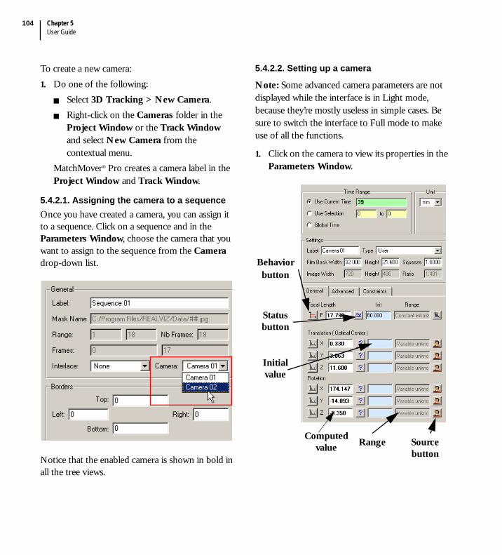
Chapter 5User Guide
104
To create a new camera:1. Do one of the following:
Select 3D Tracking > New Camera. Right-click on the Cameras folder in the Project Window or the Track Window and select New Camera from the contextual menu.
MatchMover® Pro creates a camera label in the Project Window and Track Window.
5.4.2.1. Assigning the camera to a sequenceOnce you have created a camera, you can assign it to a sequence. Click on a sequence and in the Parameters Window, choose the camera that you want to assign to the sequence from the Camera drop-down list.
Notice that the enabled camera is shown in bold in all the tree views.
5.4.2.2. Setting up a camera
Note: Some advanced camera parameters are not displayed while the interface is in Light mode, because they’re mostly useless in simple cases. Be sure to switch the interface to Full mode to make use of all the functions.
1. Click on the camera to view its properties in the Parameters Window.
Behavior button
Status button
Initial value
Source button
RangeComputed value
MatchMover® Pro 3User Guide
105
5.4.2.3. Time RangeIf needed, select a time range. Using a time range is needed when you want to tweak a parameter over a given time interval. For example, you know that the focal length between frames 20 and 30 is fixed. The camera parameter dialog time range is synchronized with the time line. when you move to a new frame, it automatically switches to this frame. When you select an interval, it switches to “Use Selection” with this interval. You can also simply select “Global Time” to apply your changes to all the frames.
5.4.2.4. Camera type settings1. Select the type of camera from the Type drop-
down list. The drop-down list contains standard camera types. These provide you with default parameter values for the selected camera type. For example, selecting Type PAL gives you a camera with the principal point in the center of the image; a pixel aspect ratio of 1.06667, a focal length initialized at 50 mm and a non-linear distortion set to 0. If you set Type to User in the camera Parameters Window, you can define your own parameters for the camera.
Note: The camera Type reverts to User if you change any value. Since the default camera types feature an image size, the camera will revert automatically to User if your sequence or image has a different size.
Note: All the predefined camera types are stored in the Data > Camera Types subdirectory of your installation. Each camera is stored in a simple “.cam” ascii file. You can easily add/edit/remove those file to customized your camera database. Just look at one of these file, and you’ll see how to do it!
2. The Film Back shows the Height and Width of the film back, either in mm or inches (use the unit combo box at the top to switch). If you change the height or width, the pixel aspect ratio changes, accordingly.
3. If an anamorphic camera was used to shoot the footage, the Lens Squeeze Factor may be different from the default value of 1.0. If this is the case, change the value in the corresponding text field.
4. The image resolution is shown by three read only fields. Width, Height and Ratio giving the size of the loaded image. Ratio is the value of the Width divided by the Height.
5.4.2.5. Camera parameter typesThere are five different camera parameter types as explained in the following table. When you create a new camera, by default the three intrinsic (or internal) camera parameters— principal point, pixel aspect ratio, and non-linear distortion— are of the type fixed. The focal length is of the type “constant initialized”.

Chapter 5User Guide
106
#This option is only available for the focal length parameter
All these types are in fact a combination of two settings. One controls the way the parameter vary
over time. is it constant or variable . The other one controls the way the computation starts.
unknown , initialized , or fixed .
These two settings are easily set though simple push buttons in the camera parameters window.Not all the parameters can use all the settings combination.
Extrinsic parameters (translation/rotation) are always variable.Distortion / Aspect Ration / Principal point can not be unknown.
5.4.2.6. Intrinsic and Extrinsic parametersEach camera has four intrinsic (or internal) parameters. focal length, radial distortion, pixel aspect ratio, and principal point, and some extrinsic parameters. translation (or optical center position), and rotation angles.Intrinsic parameters are, by default, given by the camera type (shown by a little camera icon at the end the row). These parameters can simply be overridden by changing their default value or their type (see “Camera parameter types” on page 105 for type details). They can also be “motion controlled” by providing a valid range for each
(then shown with the icon or ).Extrinsic parameters are, by default, undefined (it’s what we want to find in MatchMover® Pro!). So they’re basically user defined as variable unknown
(shown as ).
Type Description
Constant Initialized
Estimates the parameter value, starting from an approximate value that you provide and the value remains constant for all the frames.
Constant Unknown#
Computes the parameter value with no value input from you and the value remains constant for all the frames.
Fixed Uses the parameter value you provide and does not modify it.
Variable Initialized
Estimates the parameter value, starting from an approximate value that you provide. The value can change across the frames.
Variable Unknown#
Computes the parameter value with no input from you. The value can change across the frames

MatchMover® Pro 3User Guide
107
As intrinsic parameters, each of them can be “motion controlled”, either directly by the user or by importing motion control file (shown with an
icon ). See“Importing motion control data” on page 118 for details.The General tab shows the information for the Focal Length and all the camera extrinsic parameters (translation, a.k.a optical center position, and rotation angles).Click on the first row button to define if the
corresponding parameter is constant or
variable over time. For example in shots where the zoom does not change throughout the sequence, set the Focal Length to fixed or constant. If you change the focal length parameter type to variable, you can then define constraints for this parameter.
The first editable box represents the currently computed values. This can be simply edited or overridden once your shot have been calibrated for fine tuning (it has the same effect as editing the corresponding curve in the Graph Editor).Next, you have a button showing how the computed value relates to the initialization value. It can simply be a totally unknown
parameter , or its computation can starts
with an initialization value , or it can be
fixed to a given value .
Clicking on it toggles through initialized to fixed. Just empty the init value for “unknown” status.The next editable box (with a light blue background) shows the computation initial value. Next to the init value, you have a text box that sums up the parameter behavior (with a little popup to show the whole message if needed). For example, it will display the validity interval set by the user.Finally, the last button shows where the parameter configuration comes from. Either
from the camera type , from the user ,
or from on externally imported file . Depending on the current parameter configuration, clicking on it will enable following actions:
Setting up a validity rangeRemoving motion control data
Tip: If you want to export the results to software that does not handle non-linear distortion or non-centered principal points (which is the case for most 3D software), do not change the default values. MatchMover® Pro compensates for the error on these parameters by adjusting the other parameters.
Note: If an export format supports anamorphism, the appropriate parameter will be set. Otherwise, the pixel aspect ratio will be enlarged in the exported file to account for the squeeze.

Chapter 5User Guide
108
5.4.2.7. About the lens squeeze factorThe Lens Squeeze Factor changes the image or sequence shown in the 2D View. The following image shows the default image (top) the effects of applying a smaller lens squeeze factor that the default setting (bottom). This can be used in the case of anamorphic lenses.
5.4.2.8. Deleting a cameraTo delete a camera, do one of the following:
Select a camera in the Cameras folder in the Project Window or the Track Window and either:
Select Edit > Delete.Press the Delete key.
Right-click on a camera in the Cameras folder in the Project Window or the Track Window and select Delete Camera from the contextual menu.
The camera is deleted from the project.
5.4.3. Defining coordinate systems
MatchMover® Pro manages a set of user-defined coordinate systems with respect to which the cameras and 3D points are expressed. If no coordinate system is specified, MatchMover® Pro chooses an arbitrary one. You can define a coordinate system in order to facilitate the manipulation of your exported project in a 3D package. If no point relations have been set up, MatchMover® Pro aligns the coordinate system on the computed position of the camera for the first frame; the default is the camera looking towards Z and Y as Up axis, but this changes according to your project’s 3D parameters if you selected a different up axis.If no coordinate system is defined, MatchMover® Pro tries to create one from the point relations or the survey points you defined (it needs at last 4 non colinear survey points to do so).

MatchMover® Pro 3User Guide
109
There are two main advantages in defining a particular coordinate system, described below.Advantage 1 - It makes manipulation easier and more intuitive in the next stages, when virtual objects are inserted in the scene. For example, if a virtual object such as a car has to be placed on a flat surface, e.g., a road, it is very helpful to have two coordinate axes, e.g., X and Y, in the plane of that surface. Advantage 2 - It allows you to impose strong constraints on the computed 3D points and the camera move, based on clear alignments in the scene inferred from the image sequence. For example, two points that are at the same height above the floor, where the X and Y coordinate axes lie, have the same Z coordinate. These constraints help the system to compute data that is more accurate and closer to reality. In practice this applies to a lot of cases such as house walls and floors, any flat surface etc.To set a 3D coordinate system, you specify two directions. Each direction is defined as one of the following:
Passing through the origin and one point, selected from the tracked points. Passing through two points, selected from the tracked points.Normal to three points, selected from the tracked points.
The coordinate system is then defined in 3 steps.The first direction defines the first coordinate axis.The second direction defines, with the first direction, the half-plane in which the second axis is chosen.Using the two axes, MatchMover Pro finds the third and final axis that is used to build a direct orthogonal coordinate system.
You can define a coordinate system to the scene using two methods:
Defining points for the coordinate system in the coordinate label’s Parameters Window (see “Defining the coordinate system using the Parameters Window” on page 109).Snapping the axes of the Coordinate System Manipulator to 3D points in the 3D View (see “Defining a coordinate system using the Coordinate System Manipulator” on page 111).
5.4.3.1. Defining the coordinate system using the Parameters Window1. Select the points you want to include in your
coordinate system (see “Selecting tracks” on page 85).
2. Do one of the following:Select 3D Tracking > New Coordinate System.Click on the New Coordinate System icon
in the 3D Scene tab of the Main Toolbar.
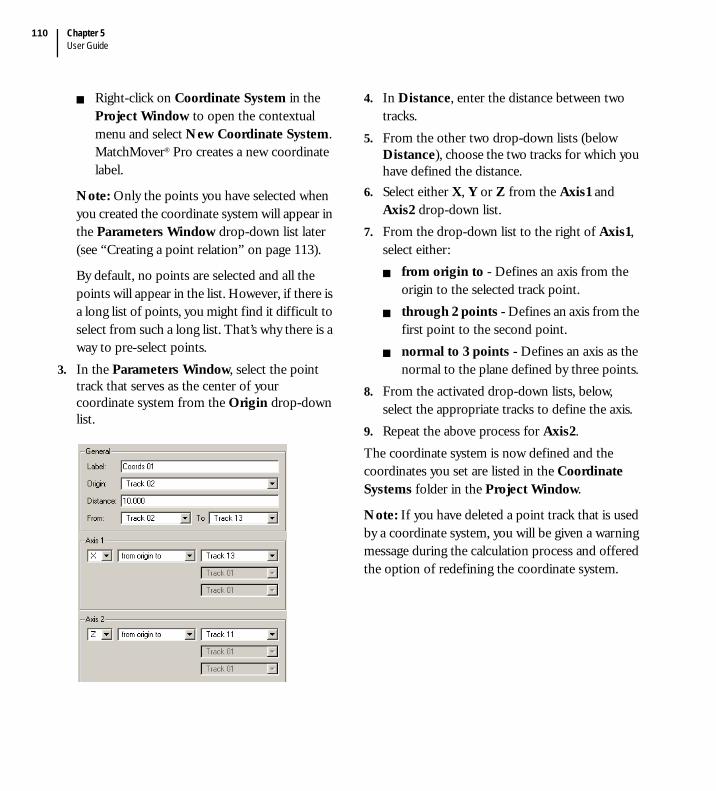
Chapter 5User Guide
110
Right-click on Coordinate System in the Project Window to open the contextual menu and select New Coordinate System. MatchMover® Pro creates a new coordinate label.
Note: Only the points you have selected when you created the coordinate system will appear in the Parameters Window drop-down list later (see “Creating a point relation” on page 113).
By default, no points are selected and all the points will appear in the list. However, if there is a long list of points, you might find it difficult to select from such a long list. That’s why there is a way to pre-select points.
3. In the Parameters Window, select the point track that serves as the center of your coordinate system from the Origin drop-down list.
4. In Distance, enter the distance between two tracks.
5. From the other two drop-down lists (below Distance), choose the two tracks for which you have defined the distance.
6. Select either X, Y or Z from the Axis1 and Axis2 drop-down list.
7. From the drop-down list to the right of Axis1, select either:
from origin to - Defines an axis from the origin to the selected track point.through 2 points - Defines an axis from the first point to the second point. normal to 3 points - Defines an axis as the normal to the plane defined by three points.
8. From the activated drop-down lists, below, select the appropriate tracks to define the axis.
9. Repeat the above process for Axis2.The coordinate system is now defined and the coordinates you set are listed in the Coordinate Systems folder in the Project Window.
Note: If you have deleted a point track that is used by a coordinate system, you will be given a warning message during the calculation process and offered the option of redefining the coordinate system.
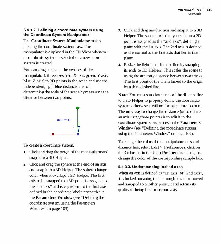
MatchMover® Pro 3User Guide
111
5.4.3.2. Defining a coordinate system using the Coordinate System ManipulatorThe Coordinate System Manipulator makes creating the coordinate system easy. The manipulator is displayed in the 3D View whenever a coordinate system is selected or a new coordinate system is created. You can drag and snap the vertices of the manipulator’s three axes (red. X-axis, green. Y-axis, blue. Z-axis) to 3D points in the scene and use the independent, light blue distance line for determining the scale of the scene by measuring the distance between two points.
To create a coordinate system.1. Click and drag the origin of the manipulator and
snap it to a 3D Helper.2. Click and drag the sphere at the end of an axis
and snap it to a 3D Helper. The sphere changes color when it overlaps a 3D Helper. The first axis to be snapped to a 3D point is assigned as the “1st axis” and is equivalent to the first axis defined in the coordinate label’s properties in the Parameters Window (see “Defining the coordinate system using the Parameters Window” on page 109).
3. Click and drag another axis and snap it to a 3D Helper. The second axis that you snap to a 3D point is assigned as the “2nd axis”, defining a plane with the 1st axis. The 2nd axis is defined as the normal to the first axis that lies in that plane.
4. Resize the light blue distance line by snapping its ends to 3D Helpers. This scales the scene to using the arbitrary distance between two tracks. The first point of the line is linked to the origin by a thin, dashed line.
Note: You must snap both ends of the distance line to a 3D Helper to properly define the coordinate system; otherwise it will not be taken into account. The only way to change the distance (or to define an axis using three points) is to edit it in the coordinate system’s properties in the Parameters Window (see “Defining the coordinate system using the Parameters Window” on page 109).
To change the color of the manipulator axes and distance line, select Edit > Preferences, click on the Color tab in the User Preferences dialog, and change the color of the corresponding sample box.
5.4.3.3. Understanding locked axesWhen an axis is defined as “1st axis” or “2nd axis”, it is locked, meaning that although it can be moved and snapped to another point, it still retains its quality of being first or second axis.

Chapter 5User Guide
112
The origin can also be moved and snapped to a different point, and although the manipulator’s axes remain in the same direction, they are now defined between two points instead of being defined from the former origin to their snap point.
5.4.3.4. Deleting a coordinate systemTo delete a coordinate system, do one of the following:
Select a coordinate system in the Coordinate Systems folder in the Project Window and either:
Select Edit > Delete.Press the Delete key.
Right-click on a coordinate system in the Coordinate Systems folder in the Project Window and select Delete Coordinate System from the contextual menu.
The coordinate system is deleted from the project.
5.4.3.5. Setting the world referenceWhen you have created several coordinate systems, you can select one to define the world reference, shown by the three axes in the bottom left corner of the Workspace.
To set the world reference:1. Select a coordinate system from the Project
Window.2. Do one of the following:
Select 3D Scene > Set World Reference. Right-click and select Set World Reference from the contextual menu.
5.4.3.6. Mapping the coordinate system to a cameraYou can also center the coordinate system on a camera at the current frame by selecting 3D Scene > Map World on Camera. This defines the coordinate system from the computed camera at the current frame so that the origin is at the optical center and the axes are that of the camera (Z is the optical axis and Y is the up axis).
5.4.4. Defining point relations
Point relations appear within the Point Relations folder in the Project Window. When you run the camera tracker, MatchMover® Pro uses the enabled point relations.
Tip: You can start running the solving process without point relations. Then, if needed, add them to improve the results.
Point relations apply to the coordinate values of one or several points. When setting a coordinate constraint, you define the coordinate (X, Y, or Z) that is shared by the selected point or points.
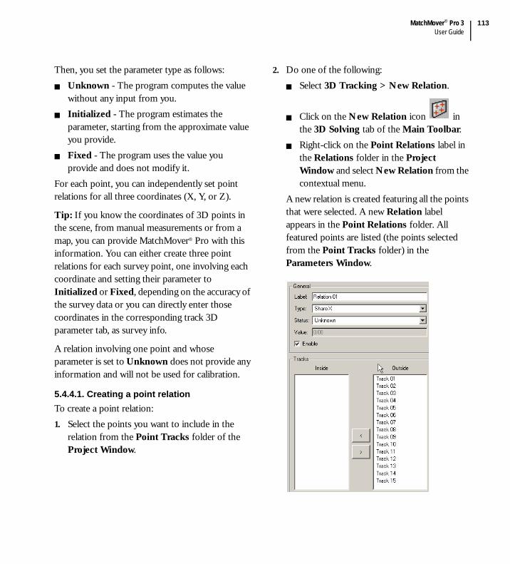
MatchMover® Pro 3User Guide
113
Then, you set the parameter type as follows:Unknown - The program computes the value without any input from you.Initialized - The program estimates the parameter, starting from the approximate value you provide.Fixed - The program uses the value you provide and does not modify it.
For each point, you can independently set point relations for all three coordinates (X, Y, or Z).
Tip: If you know the coordinates of 3D points in the scene, from manual measurements or from a map, you can provide MatchMover® Pro with this information. You can either create three point relations for each survey point, one involving each coordinate and setting their parameter to Initialized or Fixed, depending on the accuracy of the survey data or you can directly enter those coordinates in the corresponding track 3D parameter tab, as survey info.
A relation involving one point and whose parameter is set to Unknown does not provide any information and will not be used for calibration.
5.4.4.1. Creating a point relationTo create a point relation:1. Select the points you want to include in the
relation from the Point Tracks folder of the Project Window.
2. Do one of the following:Select 3D Tracking > New Relation.
Click on the New Relation icon in the 3D Solving tab of the Main Toolbar.Right-click on the Point Relations label in the Relations folder in the Project Window and select New Relation from the contextual menu.
A new relation is created featuring all the points that were selected. A new Relation label appears in the Point Relations folder. All featured points are listed (the points selected from the Point Tracks folder) in the Parameters Window.

Chapter 5User Guide
114
Note: If no points are selected from the Point Tracks folder, a new relation is created containing no points.
3. You may add extra points by selecting them from the right list box and add them to the left list box using the left arrow button.
4. From the Type field, select the relation type for points that share a coordinate. Share X, Share Y, or Share Z.
5. From the Status field, select the status for this relation. It can be Fixed, Initialized or Unknown.
6. If you select Fixed or Initialized, enter the value in the Value field. If you select Unknown, the Value field is disabled.
7. To enable this point relation, click on the Enable box to check the option.
Note: If a point belongs to several point relations of a given type (X, Y, Z), only one of these can be enabled.
Relations are shown in the 3D View as a semi-transparent rectangle in the appropriate plane. The rectangle’s edges are normal to the coordinate system axes. The relation rectangle is the smallest that contains all points featured in the relation; however the rectangle has a minimum width and height that ensures that it is not restricted to a thin line if all points are aligned on one axis.
Note: To change the color of the relations displayed in the 3D View, select Edit > Preferences, click on the Color tab in the User Preferences dialog, and change the color of the corresponding sample box.
To show or hide relation planes in the 3D View, select Display > Relations.
5.4.4.2. Deleting a relationTo delete a relation:
Select a relation in the Relations folder in the Project Window and either:
Select Edit > Delete.Press the Delete key.
Right-click on a relation in the Relations folder in the Project Window and select Delete Relation from the contextual menu.
5.4.5. Defining survey points and object mapping
The main goal of the matchmoving is to compute both the camera motion and the scene. If you know some of the properties of a scene, because you took measurements, or you have some constraints, you may know the 3D coordinates of some points of the scene. Instead of letting MatchMover® Pro compute their 3D coordinates, you can set them before the computation. Setting these “3D Survey points” has several advantages:
The coordinates of the points at the end of the computation will be exactly what you entered.

MatchMover® Pro 3User Guide
115
The points help MatchMover® Pro automatically finding the appropriate coordinate system that matches your measurements of the scene.The computation will be more robust, as all the survey points will help MatchMover® Pro finding other points in the scene.
A minimum of four survey points are required to define the coordinate system. You can either set these coordinates manually or use one of your 3D object vertex coordinates.
5.4.5.1. Setting survey points manually1. Select a track. The track’s properties are shown
in the Parameters Window.
2. Check the Survey Info options and either enter each known 3D coordinates directly in the corresponding edit box or check the Use 3D Object option, then select a 3D object in the Mesh drop-down list and a Vertex number. You can view the vertex number by selecting Display > Mesh Vertices to toggle the display of each vertex index of a 3D object from “none”, through “selected vertices” to “all vertices”.
3. Click the Use Object Transform checkbox if you want to be able to alter the original shape of your object.
4. Click on Commit Changes to validate.
5.4.5.2. Setting survey points using elasticsYou can create a survey point simply by using a 3D object vertex.In a 3D View, select the object. Drag the vertex to a position on the background image or an existing track point to make a link. You can then fine-tune its 2D position by clicking in the Magnifier window.

Chapter 5User Guide
116
A new survey point is created with coordinates mapped on the 3D object’s selected vertex. The mappings can be edited in the Parameters Window (see above).
5.4.6. Defining camera constraints
Constraints are listed the Cameras folder with the enabled constraint name in bold type. Constraints with no frames are shown as dimmed and with “empty” next to their name, to show the user that these are useless. Don’t forget to add frames to your constraints!
5.4.6.1. Focal length constraintsWith the camera focal length parameter set to Variable, it is possible to set a “constant” constraint on the focal length that can be applied to a part of your sequence. The focal length camera constraint can be of three types:
Fixed - Uses the parameter value you provide and does not modify it.Initialized - Estimates the parameter value, starting from an approximate value that you provide.Unknown - Computes the parameter value without any input from you. This is the default.
When using a focal length constraint there are three main steps. First you create the constraint, and then you edit the constraint providing MatchMover® Pro with information on its type and value. Finally, you decide which frames use this constraint for the tracking process.
5.4.6.2. Nodal pan constraintsThe nodal pan constraint fixes the optical center of the camera and limits the camera movement to rotation only. All nodal-only features (2D tracks that have no keys out of the nodal pan) are reconstructed with a median default depth.
5.4.6.3. Dolly constraintsThe dolly constraint fixes the camera motion in one direction only, either along the X-, Y-, or the Z-axis.
5.4.6.4. Planar constraintsThe planar constraint fixes the camera motion in two directions, either along the XY, XZ, or YZ planes.
5.4.6.5. Creating and enabling a constraintYou can create as many constraints as you like and toggle them by using the enable/disable check box in the constraint Parameters Window.To create a new constraint:1. Select the camera for which you want to add a
constraint in the Project Window or the Track Window.
2. Do one of the following:Select 3D Tracking > New Constraint.Right-click on the camera for which you want to create the constraint in the Project Window to open the contextual menu and select New Constraint.

MatchMover® Pro 3User Guide
117
3. Select the constraint parameter from the drop-down list in the Parameters Window.
4. When needed, select a Type from the drop-down list and enter the value in the Value text field.
5. In the Label text field, enter the name of the constraint.
6. Use the Enable check box to activate or disable the constraint for the required frame(s) of your sequence (to select frames, see “Adding frames to a constraint” on page 117).
Note: If you choose to create a focal length constraint and the camera focal length parameter is not variable, a message box opens telling you that the camera constraint will be disabled.
The frames to which the constraint applies are shown by a colored rectangle in the Track Window. The enabled constraint appears in bold in the Project Window and the Track Window.
Note: To toggle the constraint, right-click on a constraint in the Constraint folder in the Project Window or the Track Window and select Toggle Constraint from the contextual menu.
5.4.6.6. Adding frames to a constraintOn creation, a constraint is not applied to any frames and you have to add frames to the constraint and enable it. MatchMover® Pro can only use the constraint when you have provided information concerning the frames to which the constraint is applied. To do this, configure MatchMover® Pro to use the constraint on specified frames by creating a time range and adding or removing frames that use the constraint in the camera solving process.In the Track Window.1. Select the time range for the constraint by
pressing Shift+click and drag the pointer from the first frame to the last frame to include in the time range.
2. Do one of the following:Select 3D Tracking > Edit Constraint > Add Frames.Right-click in the Track Window and select Add Frames from the contextual menu.
The frames within the selected time range now have the camera constraint applied to them and MatchMover® Pro uses this information in the tracking process. The constraint label appears in bold in both the Project Window and Track Window to show that it is enabled and it applies to the current time. If another constraint already exists for the added frames, it is disabled automatically.

Chapter 5User Guide
118
For example, you have a sequence of 400 frames and you know that there is a fixed zoom for the first 300 frames and a variable zoom for the last 100 frames. In the camera Parameters Window, set the Focal Length to variable and initialized. You create a new focal length constraint and then define a time range from frames 0 to 300 in the Track View or in the Time Line. Using the function Add Frames, you apply the constraint to the frame sin the range. Finally, you set the Type according to your knowledge of the focal length in the constrained time range.
5.4.6.7. Deleting frames from a constraintTo delete frames from a constraint.In the Track Window.1. Select the time range to delete from the focal
length constraint by pressing Shift+click and drag the pointer from the first frame to the last frame to include in the time range.
2. Do one of the following:Select 3D Tracking > Edit Constraint > Remove Frames.Right-click in the Track Window to show the contextual menu and select Remove Frames.
5.4.6.8. Deleting a constraintTo delete a constraint:
Select a constraint in the Constraint folder in the Project Window or the Track Window and either:
Select Edit > Delete.Press the Delete key.
Right-click on a constraint in the Constraint folder in the Project Window or the Track Window and select Delete Constraint from the contextual menu.
5.4.7. Importing motion control data
5.4.7.1. Specifying import formatSome hardware devices are able to output what we call “motion control data”. That is, some informations about its position, rotation and/or internal parameters. All theses informations can be fed into the MatchMover® Pro solver.It can be used as an initial solution, and MatchMover® Pro will then compute the remaining missing parameters, or simply to fine-tune these data, usually not so accurate.The only need to do so is that the motion control data is stored in an ascii file, which can be easily sequentially processed (that’s to say the data are stored frame by frame). You can then use the Import File Format dialog to describe and parse your custom files.

MatchMover® Pro 3User Guide
119
1. Click on the Motion Control Import icon
in the 3D Solving tab of the Main Toolbar. The Motion Control Import dialog opens.
2. The Currently Loaded Files list displays any files that you have loaded. To remove one, select it and press Remove. You can also reload it by pressing Reload if data have changed.
3. Either select an existing file format from the drop-down list, or create a new one using the New/Edit button (see next paragraph for details).
4. Click on the Browse button to import an existing file.
Note: Click on the button to the right of the User
Data or the File Data text fields .
Set the Default Accuracy of the motion control data (either from file or from user).
Set the Status and Valid Range if needed.
5.4.7.2. Specifying the import formatClick on the New/Edit button of the Motion Control Import dialog to edit a file format. The Import File Format dialog opens.

Chapter 5User Guide
120
For example, this corresponds to the dummy file.>> begin of sample file
This is motion control data
These 2 lines will be skipped
# these are comments lines
# camera 0 with focal 25.65
# data is frame number, OCX, OCY, OCZ
0 12.34 5 2.56
1 45.3 6 3.45
1 44 7 4.55
<< end of sample file
For a new format, enter a name in the Preset Name text field or select an existing one to modify it. Press Delete to remove the current one from the list.
The Skipped Lines size specifies the number of header lines to skip not counting comments and empty lines.The Comment Lines Tag is used to specify a list of single characters selected from the list or user entered. Each line starting with such a character will be ignored. Click the Add or Del button as appropriate.The Data order specifies how data is read for each frame. Select an item from the drop-down list and click Add. Dummy data type can be used for any value/word to ignore. The default frame number starts at 0 and increases after each read frame if not specified.
Options.Use Radian Angle. default angles are specified in degrees.Reverse Rotation. rotation angles are reversed after import.The Use Frame Shift specifies an offset for the frame index.Default Value Range. this range will be applied to all imported data. You can also set these parameters in the Motion Control Import dialog.Default Optical Center. this value is added to all imported optical center.Default Rotation. this value is added to all imported rotation.
All changes can be reset using the Reset Changes button.
Motion control is then automatically applied for all imported data.A dummy motion control constraint is then created under the corresponding camera, to show where motion control data is available and used.
5.4.8. Solving for the camera
This process reconstructs the 3D points corresponding to the 2D tracks and computes the camera path for all the sequences or frames and all the objects in one solve. There are several stages:1. Select key and reference frames2. Solve the two reference frames

MatchMover® Pro 3User Guide
121
3. Solve all the keyframes4. Solve all other frames5. Solve all the 3D points.This process is done first for the main camera (looking at a static scene), and then for all the mobile rigid objects.At the same time the process computes the camera parameters and reconstructs the 3D coordinates of the 2D computed points.
Note: Camera solving is an automatic step in the Automatic Tracking process (see “Running the automatic 2D tracking” on page 79).
Each camera parameter—focal length, principal point, pixel aspect ratio and non-linear distortion— has a value that varies or remains constant throughout the sequence and is either known or unknown. Optionally, you can specify these parameters. Doing so helps the camera solver to give more accurate and faster results. See “Setting up a camera” on page 104.
5.4.8.1. Setting frames to solveBy default, MatchMover® Pro processes all frames in the Work Area. However, you may have for example, blurred images or an obscured frame, for which the camera will not solve. You can select the frame that you want to solve and therefore ignoring the frames that will not solve.
1. Use Shift+click and drag the pointer to define a time range in the Work Area (see “Defining a Work Area” on page 58).
2. Do one of the following:Select 3D Tracking > Set Frames.Right-click in the Track View and select Set Frames from the contextual menu.
3. Select one of the following:To Be Solved - When you run the camera solving process, MatchMover® Pro process the marked frames.Do Not Solve - When you run the camera solving process, MatchMover® Pro does not process the marked frames.
Note: Frames that will not be solved are marked with a black bar in the Track Window Graded Ruler.
5.4.8.2. Running the camera solverTo run the camera solver, do one of the following:
Select 3D Tracking > Solve for Camera.Click on the Run/Stop Camera Solving icon
in the 3D Tracking tab of the Main Toolbar. Right-click in the Cameras folder in the Project Window or the Track Window and select Solve for Camera from the contextual menu.Press F9.
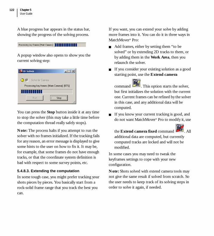
Chapter 5User Guide
122
A blue progress bar appears in the status bar, showing the progress of the solving process.
A popup window also opens to show you the current solving step:
You can press the Stop button inside it at any time to stop the solver (this may take a little time before the computation thread really safely stops).
Note: The process halts if you attempt to run the solver with no frames initialized. If the tracking fails for any reason, an error message is displayed to give some hints to the user on how to fix it. It may be, for example, that some frames do not have enough tracks, or that the coordinate system definition is bad with respect to some survey points, etc.
5.4.8.3. Extending the computationIn some tough case, you might prefer tracking your shots pieces by pieces. You basically start from a rock-solid frame range that you track the best you can.
If you want, you can extend your solve by adding more frames into it. You can do it in three ways in MatchMover® Pro:
Add frames, either by setting them “to be solved” or by extending 2D tracks to them, or by adding them in the Work Area, then you relaunch the solver.If you consider your existing solution as a good starting point, use the Extend camera
command . This option starts the solver, but first initializes the solution with the current one. Current frames can be refined by the solver in this case, and any additional data will be computed.If you know your current tracking is good, and do not want MatchMover® Pro to modify it, use
the Extend camera fixed command . All additional data are computed, but currently computed tracks are locked and will not be modified.
In some cases you may need to tweak the keyframes settings to cope with your new configuration.Note: Shots solved with extend camera tools may not give the same result if solved from scratch. So the user needs to keep track of its solving steps in order to solve it again, if needed.

MatchMover® Pro 3User Guide
123
5.5. Fine-tuning the results
5.5.1. Inspecting the results
Once your shot has been solved, you will need to check the quality of the solving. Is it accurate enough to fit your needs or are there some frames that are not solved correctly? MatchMover® Pro provides several ways to check the tracking.
5.5.1.1. Checking the computation quality in the Track WindowThe quickest and simplest method is to examine the colored line in the Track Window Graded Ruler (see “The Track View” on page 54) that correspond to the residual value for a given frame (the average of all the track residuals present at that frame).
This colored line indicates the quality of the tracking according to the residual value thresholds set in the Preferences dialog (see “Configuring the tracker” on page 92).
Gray lines indicate frames that are not computed and black lines are ignored since these frames were set to “do not solve” before the camera solving process. Green lines mean good solving, through yellow (fair) to red (bad). So, you have an instant feedback of the average quality of all your frames. It’s almost the same for all the track points.You can really easily spot out the bad areas, a bad time range, or bad tracks, if any, and concentrate on them. Anyway, for further inspection, MatchMover® Pro provides the other solutions detailed in the next sections.
5.5.1.2. Checking the position of 3D HelpersAnother quick and simple method of checking the results involves using a 3D View. When working in the 3D View, each reconstructed track is displayed using a 3D helper. The tracks are displayed by a default 3D cone, but can be changed to a pyramid in the Preferences dialog. So if you look through the computed camera (using Lock on Camera
), you should easily see if orientation and relative depth of the helpers fit the real footage. By playing the sequence, you’ll also be able to check how accurate the 3D helpers reproject on the background. Accurate tracking results in natural and synchronized helper motion. Mobile points are displayed with a different customizable color, and are animated while sequence is played.
colored line

Chapter 5User Guide
124
You can easily change the 3D helper size, either in the global parameter window, which is displayed when nothing is selected (just hit Esc), or in the Preferences dialog (press P).
5.5.1.3. Examining the computation quality in the Track Status ViewThe Track Status View shows a graphical representation of the pixel residuals for each track in a frame. Use this to isolate quickly the tracks or frames with a high-pixel residual (see “The Track Status View” on page 56 for details on how to use it).
5.5.1.4. Examining the computation quality in the Survey WindowUse the Survey Window to analyze the results of 3D tracking and to isolate specific frames or points where adjustment may be necessary. Select Window > Survey Window.The Survey Window shows values of the distance in pixels between a 2D point and the projection of a 3D point on the camera. These are called the residuals. Numeric information is shown for the points and/or frames and their average error values.By default the Survey Window shows two columns, the points and the 3D residuals, but you can display a maximum of four columns.To change the display:1. Do one of the following:
Select Display > Survey Mode.Right-click in the Survey Window.
2. Select either:Points to show the point number and 3D tracking residual data. Frames to show the frame number and 3D tracking residual data. Points & Frames to show the point number, frame number, the 2D tracking quality residual data, and 3D tracking residual data. The 2D tracking quality residual data ranges from 0 to 1. A score of 0 indicates a poor tracking quality; 1 indicates perfect tracking quality.
Selecting Points mode allows you to double-click on a track in the first column to select the track in all views. Selecting Frames or Points and Frames allows you to double-click in the first column to change the current time.
By default, the data is sorted for the Points column in ascending order.To sort the data in the 3D Residual column:1. Click on the 3D Residual column header to
sort the data in descending order.2. Re-click on the 3D Residual column header to
sort the data in ascending order.A sort can be done for other columns by repeating the above procedure substituting the required header.
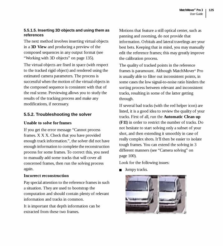
MatchMover® Pro 3User Guide
125
5.5.1.5. Inserting 3D objects and using them as referencesThe next method involves inserting virtual objects in a 3D View and producing a preview of the composed sequences in any output format (see “Working with 3D objects” on page 135). The virtual objects are fixed in space (with respect to the tracked rigid object) and rendered using the estimated camera parameters. The process is successful when the motion of the virtual objects in the composed sequence is consistent with that of the real scene. Previewing allows you to study the results of the tracking process and make any modifications, if necessary.
5.5.2. Troubleshooting the solver
Unable to solve for framesIf you get the error message “Cannot process frames. X X X. Check that you have provided enough track information.”, the solver did not have enough information to complete the reconstruction process for some frames. To correct this, you need to manually add some tracks that will cover all concerned frames, then run the solving process again.Incorrect reconstructionPay special attention to the reference frames in such a situation. They are used to bootstrap the computation and should contain plenty of relevant information and tracks in common. It is important that depth information can be extracted from these two frames.
Motions that feature a still optical center, such as panning and zooming, do not provide that information. Orbitals and lateral travelings are your best bets. Keeping that in mind, you may manually edit the reference frames; this may greatly improve the calibration process.The quality of tracked points in the reference frames is paramount. Although MatchMover® Pro is usually able to filter out inconsistent points, in some cases the low signal-to-noise ratio hinders the sorting process between relevant and inconsistent tracks, resulting in some of the latter getting through.If several bad tracks (with the red helper icon) are listed, it is a good idea to review the quality of your tracks. First of all, run the Automatic Clean up (F11) in order to restrict the number of tracks. Do not hesitate to start solving only a subset of your shot, and then extending it smoothly in case of really complex shots. It’ll then be easier to isolate tough frames. You can extend the solving in 3 different manners (see “Camera solving” on page 100).Look for the following issues:
Jumpy tracks.

Chapter 5User Guide
126
Jumpy tracks can be found by carefully looking at track paths. A sudden bump in the path may mean that the track “jumped” from one feature to another or it may also be caused by a jerky camera motion. Usually these can be manually edited and corrected or simply deleted.Periodic textures, such as windows of a building.
This is a special case of jumpy track, the tracker was fooled by the repeating pattern. Make sure the corners match or remove the tracks altogether.
Non-physical points.
The intersection of the border of an object and a line in the background represents a 3D point whose position in space changes with the camera position; it is not a physical 3D point. More generally, any 3D point whose position in space depends on the camera position (for example, the occluding edge of a cylinder) should be removed.
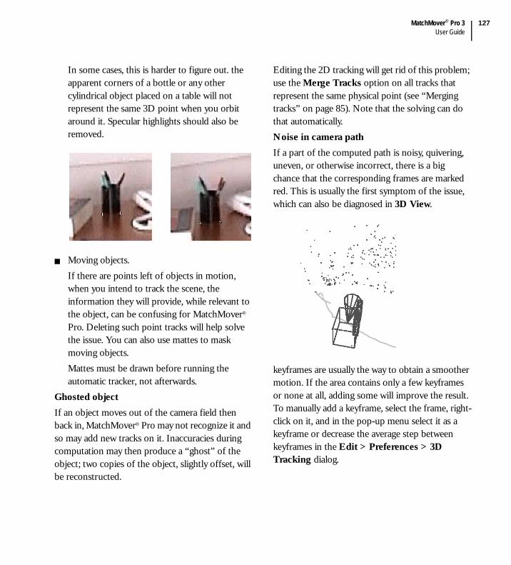
MatchMover® Pro 3User Guide
127
In some cases, this is harder to figure out. the apparent corners of a bottle or any other cylindrical object placed on a table will not represent the same 3D point when you orbit around it. Specular highlights should also be removed.
Moving objects.If there are points left of objects in motion, when you intend to track the scene, the information they will provide, while relevant to the object, can be confusing for MatchMover® Pro. Deleting such point tracks will help solve the issue. You can also use mattes to mask moving objects. Mattes must be drawn before running the automatic tracker, not afterwards.
Ghosted objectIf an object moves out of the camera field then back in, MatchMover® Pro may not recognize it and so may add new tracks on it. Inaccuracies during computation may then produce a “ghost” of the object; two copies of the object, slightly offset, will be reconstructed.
Editing the 2D tracking will get rid of this problem; use the Merge Tracks option on all tracks that represent the same physical point (see “Merging tracks” on page 85). Note that the solving can do that automatically.Noise in camera pathIf a part of the computed path is noisy, quivering, uneven, or otherwise incorrect, there is a big chance that the corresponding frames are marked red. This is usually the first symptom of the issue, which can also be diagnosed in 3D View.
keyframes are usually the way to obtain a smoother motion. If the area contains only a few keyframes or none at all, adding some will improve the result. To manually add a keyframe, select the frame, right-click on it, and in the pop-up menu select it as a keyframe or decrease the average step between keyframes in the Edit > Preferences > 3D Tracking dialog.
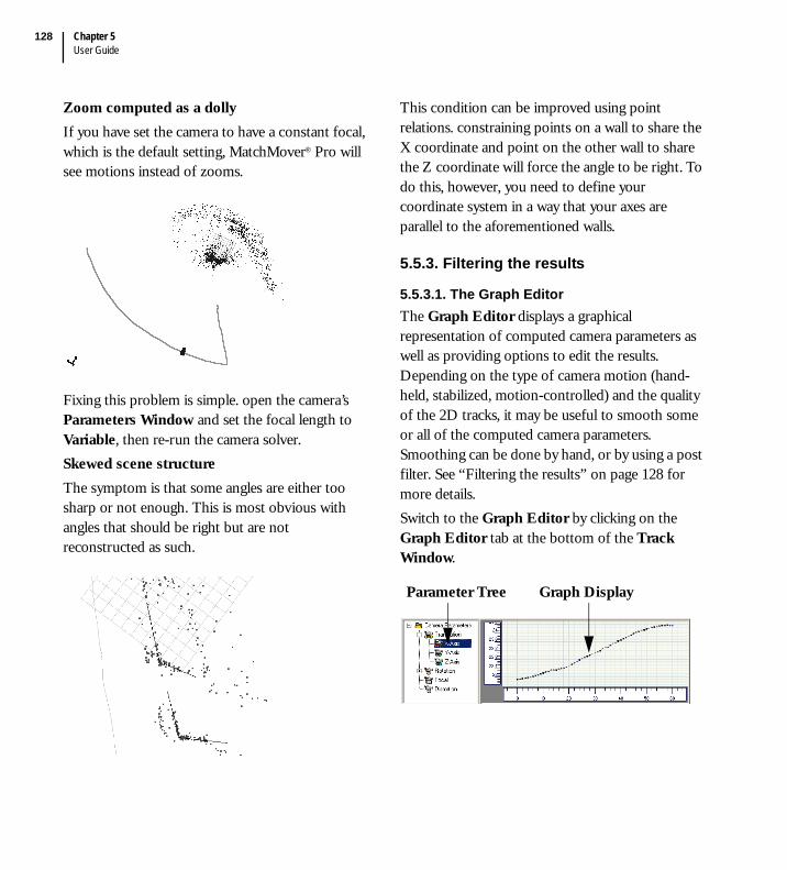
Chapter 5User Guide
128
Zoom computed as a dollyIf you have set the camera to have a constant focal, which is the default setting, MatchMover® Pro will see motions instead of zooms.
Fixing this problem is simple. open the camera’s Parameters Window and set the focal length to Variable, then re-run the camera solver.Skewed scene structureThe symptom is that some angles are either too sharp or not enough. This is most obvious with angles that should be right but are not reconstructed as such.
This condition can be improved using point relations. constraining points on a wall to share the X coordinate and point on the other wall to share the Z coordinate will force the angle to be right. To do this, however, you need to define your coordinate system in a way that your axes are parallel to the aforementioned walls.
5.5.3. Filtering the results
5.5.3.1. The Graph EditorThe Graph Editor displays a graphical representation of computed camera parameters as well as providing options to edit the results. Depending on the type of camera motion (hand-held, stabilized, motion-controlled) and the quality of the 2D tracks, it may be useful to smooth some or all of the computed camera parameters. Smoothing can be done by hand, or by using a post filter. See “Filtering the results” on page 128 for more details.Switch to the Graph Editor by clicking on the Graph Editor tab at the bottom of the Track Window.
Parameter Tree Graph Display

MatchMover® Pro 3User Guide
129
In the Parameter Tree, you can select the parameter you want display. The corresponding curve is then shown in the graph display. The available parameters are.
The Graph Display shows the curve representing the selected parameter value over time. The X-axis always represents the time in frames, and the Y-axis represents the parameter value. For example, rotation is expressed in degrees, translation is in the units defined in the coordinate system, and the focal length is in millimeters. Each curve is shown as a continuous line joining the points calculated for each frame. The color of a curve is determined by the parameter it represents. One or more parameters can be selected and displayed at a time by using Shift or Ctrl+right-click.
The points used to extrapolate a curve are displayed in the Graph Display and can be edited.
Click to close the Graph Editor.To restore the view, select Window > Track Window.To fit the graph to the viewport, select Graph > Fit or right-click in the Graph Editor and select Fit from the contextual menu.
5.5.3.2. The Graph Editor ToolboxThe Graph Editor Toolbox is displayed when you open the Graph Editor.
This toolbox provides access to the MatchMover® Pro post-filtering options. As you move the pointer over the graph, the Graph Editor Toolbox displays information on the position of the cursor (time and position) and the key number and its value in read-only fields.
Folder Description
Translation Contains the three components of camera translation, named X-, Y-, and Z-axes.
Rotation Contains the three components of camera rotation, named X-, Y-, and Z-axes.
Focal Shows how camera focal length varies over time.
Distortion Shows how lens distortion varies over time.

Chapter 5User Guide
130
If you select a key, or multiple keys using a rubber band selector or pressing Shift while selecting more keys, the keys are listed and you can set their value by entering a number in the Value field and clicking on Set Value. The filter options are displayed in the Graph Editor Toolbox (see “Smoothing a curve using post filters” on page 130) and once you have edited a camera parameter, use the recompute function
to recalculate the effects of editing on the other parameters.Toggle the Graph Editor Toolbox display by selecting Graph > Graph Editor > Editor Toolbox or use the contextual menu.
5.5.3.3. Toggling the display gridTo toggle the grid display in the Graph Editor:1. Click in the Graph Display to select it.2. Do one of the following:
Select Graph > Show Grid to display the grid.Right-click in the Graph Editor or the Track Status View and select Show Grid from the contextual menu.
A checkmark appears beside the option indicating that the option is activated.
5.5.3.4. Locking the grid axesTo lock the X- or Y-axis of the grid, either:
Select Graph > X Locked or Y-Locked. Right-click in the Graph Editor or the Track Status View and click on X Locked or Y-Locked in the contextual menu.
A checkmark appears beside the option indicating that the option is activated.
5.5.3.5. Smoothing a curve using post filtersThe Graph Editor allows you to modify curves and point values using post filters. MatchMover® Pro has four types of post filter:
Spline - Replaces frame parameters with the values obtained from spline interpolation of the neighboring values. This is useful when one frame looks “jumpy” and neighboring frames are not. In this mode, you can change the tangent of the curve at a given point to create a smoother curve. Linear - Replaces frame parameters with the values obtained by creating a linear curve between the first and last selected frame.Smooth - Applies a smoothing filter to the computed values. This is useful to remove the small vibrations that can appear in the computed camera path even when the actual camera motion is smooth.
For example, if the original camera path computed by MatchMover® Pro is too jagged, as shown below, we will use the smoothing function to improve it.
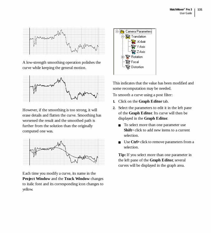
MatchMover® Pro 3User Guide
131
A low-strength smoothing operation polishes the curve while keeping the general motion.
However, if the smoothing is too strong, it will erase details and flatten the curve. Smoothing has worsened the result and the smoothed path is further from the solution than the originally computed one was.
Each time you modify a curve, its name in the Project Window and the Track Window changes to italic font and its corresponding icon changes to yellow.
This indicates that the value has been modified and some recomputation may be needed.To smooth a curve using a post filter:1. Click on the Graph Editor tab.2. Select the parameters to edit it in the left pane
of the Graph Editor. Its curve will then be displayed in the Graph Editor.
To select more than one parameter use Shift+click to add new items to a current selection.Use Ctrl+click to remove parameters from a selection.
Tip: If you select more than one parameter in the left pane of the Graph Editor, several curves will be displayed in the graph area.

Chapter 5User Guide
132
3. Do one of the following:Select a frame range. A frame range is a set of frames. In some situations, you may find that you only need to edit a limited part of your sequence. In the graph area, press Shift+click and drag the mouse horizontally to include the frames you want to select.Select a curve point by clicking on it. This will turn the point into a small red circle. If you are in the Spline mode, it will also activate the display of the curve tangents at this point.
Note: If a time range exists, the filter is applied only to the frames within the time range. Frames outside the time range are unaffected. If no time range exists, the whole of the current sequence is filtered.
4. Do one of the following:Select the relevant filter from the Graph Editor Toolbox.
to convert a time range to spline.
to convert a time range to linear.
to smooth a time range. Edit the number in the corresponding text field to define the strength of the smoothing.
You can also set this value in the Smoothing Strength text field by selecting Edit > Preferences > 3D Tracking.Right-click in the Graph Editor and select Filter and then a post filter from the contextual menu.
MatchMover® Pro applies the post filter to the selection.
5.5.3.6. Modifying a curve manuallyFor more controllable editing of a curve, you can edit points manually.1. Place the pointer over the curve point you wish
to edit. The pointer changes to .2. Click on the point. The point changes to a red
label with a pencil indicating that it is selected.
3. Drag and drop the point to its new position.
Tip: You can do exactly the same using multiple points selection.
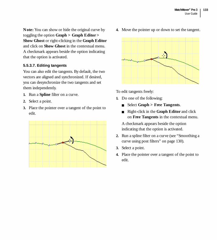
MatchMover® Pro 3User Guide
133
Note: You can show or hide the original curve by toggling the option Graph > Graph Editor > Show Ghost or right-clicking in the Graph Editor and click on Show Ghost in the contextual menu. A checkmark appears beside the option indicating that the option is activated.
5.5.3.7. Editing tangentsYou can also edit the tangents. By default, the two vectors are aligned and synchronized. If desired, you can desynchronize the two tangents and set them independently.1. Run a Spline filter on a curve.2. Select a point.3. Place the pointer over a tangent of the point to
edit.
4. Move the pointer up or down to set the tangent.
To edit tangents freely:1. Do one of the following:
Select Graph > Free Tangents.Right-click in the Graph Editor and click on Free Tangents in the contextual menu.
A checkmark appears beside the option indicating that the option is activated.
2. Run a spline filter on a curve (see “Smoothing a curve using post filters” on page 130).
3. Select a point.4. Place the pointer over a tangent of the point to
edit.
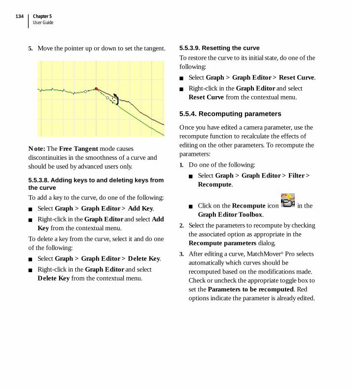
Chapter 5User Guide
134
5. Move the pointer up or down to set the tangent.
Note: The Free Tangent mode causes discontinuities in the smoothness of a curve and should be used by advanced users only.
5.5.3.8. Adding keys to and deleting keys from the curve To add a key to the curve, do one of the following:
Select Graph > Graph Editor > Add Key.Right-click in the Graph Editor and select Add Key from the contextual menu.
To delete a key from the curve, select it and do one of the following:
Select Graph > Graph Editor > Delete Key.Right-click in the Graph Editor and select Delete Key from the contextual menu.
5.5.3.9. Resetting the curveTo restore the curve to its initial state, do one of the following:
Select Graph > Graph Editor > Reset Curve.Right-click in the Graph Editor and select Reset Curve from the contextual menu.
5.5.4. Recomputing parameters
Once you have edited a camera parameter, use the recompute function to recalculate the effects of editing on the other parameters. To recompute the parameters:1. Do one of the following:
Select Graph > Graph Editor > Filter > Recompute.
Click on the Recompute icon in the Graph Editor Toolbox.
2. Select the parameters to recompute by checking the associated option as appropriate in the Recompute parameters dialog.
3. After editing a curve, MatchMover® Pro selects automatically which curves should be recomputed based on the modifications made. Check or uncheck the appropriate toggle box to set the Parameters to be recomputed. Red options indicate the parameter is already edited.

MatchMover® Pro 3User Guide
135
It also suggests parameters for recomputation and checks them automatically.
4. Select a time frame in the Time parameters text fields or drop-down menu. Choose from Full File, Time Range, or User.
5. Press the Recompute button.
Note: When recomputing camera parameters in the Graph Editor, the items Distortion and Focal Length in the Recompute parameters box are by default disabled to keep the focal length and the distortion constant.
MatchMover® Pro re-estimates the specified camera parameters from the 3D points, the 2D tracks and the modified camera parameters without changing the 3D points. For example, with a variable zoom, it is common for the system to produce a camera path that is jagged along the depth axis. MatchMover® Pro compensates for slight errors along this axis by adjusting the focal length.
To avoid this, you can first filter the focal length then re-compute the rotation and translation.
5.6. Working with 3D objects
MatchMover® Pro provides you with a set of objects called 3D primitives. 3D primitives are basic 3D shapes such as cubes, cones or spheres. It is also possible to import an object or a scene in the OBJ format. You can use a 3D object as it appears or edit it, using one of the manipulators. The virtual objects are fixed in space, and rendered using the estimated camera parameters. The process is successful when the motion of the virtual objects in the composed sequence is consistent with that of the real scene. You can also use 3D objects to define survey points mapping by dragging the mouse from one vertex to the image plane (see “Setting survey points using elastics” on page 115).To insert a new primitive:1. Do one of the following:
Select 3DScene > New Primitive.Right-click in the 3D View or on the 3D Scene folder in the Project Window and select New Primitive from the contextual menu.
2. Select the type of new primitive from the sub menu. Plane, Cube, Pyramid, Dihedron, Sphere, Cylinder, Cone, or Light.

Chapter 5User Guide
136
Alternatively, you can select a primitive from the 3D Scene tab of the Main Toolbar (see “Interface overview” on page 41) by clicking on one of the following icons.
MatchMover® Pro inserts the new primitive in the scene at the origin of the coordinate system and selects it.
5.6.1. Importing 3D objects
You can import 3D objects as files in the OBJ format. Only polygonal objects are imported. The imported objects are imported along with texture information, and can be manipulated in the same manner as the 3D primitives.1. Do one of the following:
Select 3D Scene > Import Scene.Right-click on the 3D Scene folder in the Project Window or anywhere in the 3D View and select Import Scene from the contextual menu. The Import Scene dialog opens.
2. Select the OBJ file to import and click OK.
5.6.2. Viewing 3D primitives and objects
You can position the viewing camera to view the different faces of a 3D object or primitive by selecting View > Set 3D Viewing and one of the following options.
Front - Shows the front view of the object relative to the active coordinate system.Top - Shows the top view of the object relative to the active coordinate system.Side - Shows the side view of the object relative to the active coordinate system.Perspective - Changes the scene’s perspective.Orthographic - Shows the scene without perspective.
5.6.3. Deleting a 3D primitive or an object
To delete a primitive or a 3D object, do one of the following:
Select an object in the 3D Scene folder in the Project Window or in the 3D View and either:
Select Edit > Delete.Press the Delete key.
Right-click an object in the 3D Scene folder in the Project Window and select Delete Object from the contextual menu.
The object is deleted from the project.
5.6.4. Editing 3D primitives and objects
You can either edit primitives in the Parameters Window (see “3D primitives and objects Parameters Window” on page 139) or by using MatchMover® Pro’s three manipulators.
General manipulator Translate/Scale manipulator Alignment manipulator

MatchMover® Pro 3User Guide
137
The different manipulators provide specific object manipulation possibilities, enabling you to edit any object placed within the 3D View. By default, when you create a new primitive or new light, the General manipulator surrounds the object.1. To access the manipulators either:
Click on an object and select 3D Scene > Select Manipulator.Right-click on an object in the 3D View and select Select Manipulator from the contextual menu.
2. Choose either General, Translate/Scale, or Alignment.
The manipulator changes. Notice that the same manipulator is assigned to all new objects. Toggle between the manipulators using the Tab key.
Note: To change the color of the manipulator or the manipulator’s active handle, select Edit > Preferences, click on the Color tab in the User Preferences dialog, and change the color of the corresponding sample box.
5.6.4.1. The General manipulator
The General manipulator allows you to carry out the following actions:
Independent scaling along to the selected axes by clicking and dragging the cylinder.Rotation around the selected axes by clicking and dragging one of the three circles surrounding the object.Translation in the plane perpendicular to the camera by clicking and dragging the cone.Translation along two axes by clicking and dragging the central cube.
5.6.4.2. The Translate/scale manipulator
The Translate/scale manipulator allows you to carry out the following actions:
Independent translation along the selected axes by clicking and dragging the cone.Translation in the plane of the selected manipulator face by selecting and dragging a face.

Chapter 5User Guide
138
Symmetrical scaling in relation to the center of the manipulator by clicking and dragging a cube in the edge of the manipulator.Symmetrical scaling in relation to the center of the manipulator along three axes by clicking and dragging a corner cube.
5.6.4.3. The Alignment manipulatorThe Alignment manipulator, more complex than the other two manipulators, defines the alignment of manipulator axes and pivots.
The Alignment manipulator allows you to carry out the following actions:
Align the object with the principal axis by clicking and dragging the sphere.Align the object with the central pivot by clicking and dragging the center cube. Align the object with the orientation axes by clicking and dragging the cone.Snap the manipulator to an object’s vertex, edge, or faces, track points, and other primitives in the scene (see below).
5.6.4.4. Snapping the manipulator to elementsPress Shift and drag and drop a manipulator element on a vertex, an edge, or a face of the object, track points, and other primitives. The orientation axes and principal axis align an object whereas the center cube translates it.When you place the pointer over an element, it changes to reflect the type of element you are snapping to.
when snapping to a vertex or a 3D Helper.
when snapping to an edge of an object.
when snapping to a face of the object.
5.6.4.5. Aligning the manipulators’ pivotMatchMover® Pro allows you to align the manipulators’ pivot with object elements.When any of the manipulators are activated.1. Do one of the following:
Select 3DScene > Edit Pivot.Right-click on an object in the 3D View and select Edit Pivot from the contextual menu.
2. Select from the pivot alignment options in menu:
Orient Pivot - Aligns the pivot with a face of the selected object (see “Orientating the manipulator’s pivot” on page 139).
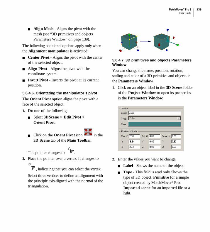
MatchMover® Pro 3User Guide
139
Align Mesh - Aligns the pivot with the mesh (see “3D primitives and objects Parameters Window” on page 139).
The following additional options apply only when the Alignment manipulator is activated:
Center Pivot - Aligns the pivot with the center of the selected object.Align Pivot - Aligns the pivot with the coordinate system.Invert Pivot - Inverts the pivot at its current position.
5.6.4.6. Orientating the manipulator’s pivotThe Orient Pivot option aligns the pivot with a face of the selected object. 1. Do one of the following:
Select 3DScene > Edit Pivot > Orient Pivot.
Click on the Orient Pivot icon in the 3D Scene tab of the Main Toolbar.
The pointer changes to . 2. Place the pointer over a vertex. It changes to
, indicating that you can select the vertex.
Select three vertices to define an alignment with the principle axis aligned with the normal of the triangulation.
5.6.4.7. 3D primitives and objects Parameters WindowYou can change the name, position, rotation, scaling and color of a 3D primitive and objects in the Parameters Window.1. Click on an object label in the 3D Scene folder
of the Project Window to open its properties in the Parameters Window.
2. Enter the values you want to change.Label - Shows the name of the object.Type - This field is read only. Shows the type of 3D object. Primitive for a simple object created by MatchMover® Pro, Imported scene for an imported file or a light.
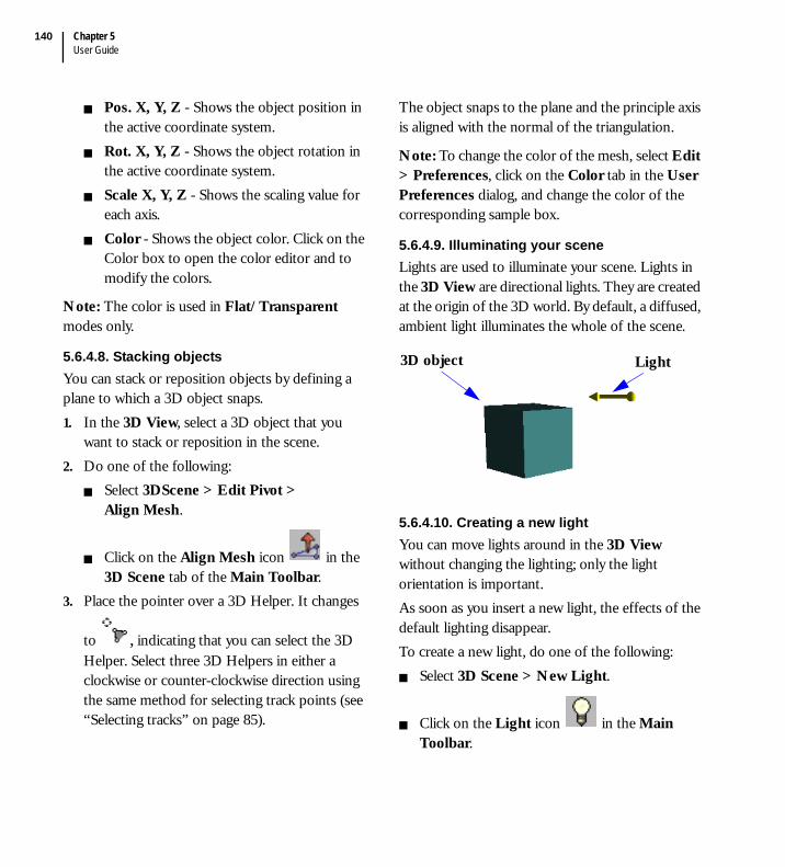
Chapter 5User Guide
140
Pos. X, Y, Z - Shows the object position in the active coordinate system.Rot. X, Y, Z - Shows the object rotation in the active coordinate system.Scale X, Y, Z - Shows the scaling value for each axis.Color - Shows the object color. Click on the Color box to open the color editor and to modify the colors.
Note: The color is used in Flat/Transparent modes only.
5.6.4.8. Stacking objectsYou can stack or reposition objects by defining a plane to which a 3D object snaps.1. In the 3D View, select a 3D object that you
want to stack or reposition in the scene.2. Do one of the following:
Select 3DScene > Edit Pivot > Align Mesh.
Click on the Align Mesh icon in the 3D Scene tab of the Main Toolbar.
3. Place the pointer over a 3D Helper. It changes
to , indicating that you can select the 3D Helper. Select three 3D Helpers in either a clockwise or counter-clockwise direction using the same method for selecting track points (see “Selecting tracks” on page 85).
The object snaps to the plane and the principle axis is aligned with the normal of the triangulation.
Note: To change the color of the mesh, select Edit > Preferences, click on the Color tab in the User Preferences dialog, and change the color of the corresponding sample box.
5.6.4.9. Illuminating your sceneLights are used to illuminate your scene. Lights in the 3D View are directional lights. They are created at the origin of the 3D world. By default, a diffused, ambient light illuminates the whole of the scene.
5.6.4.10. Creating a new lightYou can move lights around in the 3D View without changing the lighting; only the light orientation is important. As soon as you insert a new light, the effects of the default lighting disappear.To create a new light, do one of the following:
Select 3D Scene > New Light.
Click on the Light icon in the Main Toolbar.
Light3D object

MatchMover® Pro 3User Guide
141
Right-click on the 3D Scene folder in the Project Window or anywhere in the 3D View and select New Light from the contextual menu.
A new light appears in the 3D Scene folder of the Project Window.
Note: To change the default color of the lights, select Edit > Preferences, click on the Color tab in the User Preferences dialog, and change the color of the corresponding sample box.
5.6.4.11. Editing lightsBy default, when you place a light within a scene it is surrounded by the General manipulator. Lights are edited in the same manner as physical 3D primitives, see “Editing 3D primitives and objects” on page 136.
5.6.4.12. Changing the size of the non-physical objectsTo change the size of any non-physical objects in a scene, for example, lights and cameras.1. Select Edit > Preferences > Display.2. Enter a number in the 3D Icon Size text field.
A smaller number reduces the size of the non-physical object; a greater number increases their size.
The 3D Icon Size is also reported in the Global Parameters Window.
5.7. Rendering the sequence
To generate a preview sequence you can create a sequence of any available format, depending on your platform, for example, AVI, QuickTime®, single image files, using the Render function. By doing this you can examine the estimated camera path quality.If you have configured the render process, select 3D Scene > Render. If you have not configured the render process:1. Select 3D Scene > Render Setup. The Render
Setup dialog opens.
2. The File Name field automatically points to the last directory used for rendering. If you click on Render without entering a filename, a dialog pops up asking you to enter one. If this is the case, choose a destination directory and enter a File Name.

Chapter 5User Guide
142
3. From the drop-down Size list, choose the size you want for the rendered image. Full image renders the whole image. Crop to viewport only renders the portion of the image visible in the current viewport at the moment you open the Render Setup dialog. Each time you open it the area to render is updated.
4. From the Resolution drop-down list, choose the resolution percentage. Choose the option User to define a custom size.
5. To determine the section of the sequence to render, select an option in the Length drop-down list.
Full Length renders the whole sequence.Time range renders the sequence within the time range at the moment of the render.User renders the sequence frames entered in the adjacent fields.Work Area renders the sequence within the selected Work Area.
6. Check the Antialiasing box if you want the object edges to have a clearer appearance. This is important if you want to check for very small, sub-pixel vibrations of the object, but slow down the process.
7. If you have distortion in the original image, check the Distortion box. This applies the non-linear distortion to the object while leaving the background image intact.
Tip: If you do not check this box in a shot where you computed a non-zero distortion, the objects appear to slide slightly with respect to the background image motion. This is normal, as they are rendered without taking into account the geometric parameters of the camera.
8. Select a render opacity for the 3D objects from the drop-down list:
Flat - Solid objectsWireframe objectsTexture - Solid objects textured with the background from the corresponding imported objects.
9. Click the Render Only 2D Visible checkbox to render only the 3D points in a frame if the corresponding 2D track is defined for this frame.
10. Click the Render Hidden Points checkbox to render hidden tracks. Hidden tracks are not rendered by default.
11. Click Setup if you want to customize the output format (compression factor).
12. If you want to save and run the rendering process immediately click on the Render button. If you want to save your setup but not run the rendering process click on the Close button.

MatchMover® Pro 3User Guide
143
5.8. Input-output
5.8.1. Importing files
You can import files with the following formats:REALVIZ Ascii Point Tracks (*.rz2)REALVIZ Ascii Camera 3D Tracks (*.rz3)Alias|Wavefront™ Ascii Model (*.obj).
To import a file:1. Select File > Import to open the dialog.
2. Use the Files of type drop-down list to show files with the same format only or select All Files to show all files.
3. Select the file to import and click Open.
Tip: You can simply drag and drop any kind of known file in the Workspace area to automatically import it.
5.8.1.1. Importing REALVIZ Ascii filesIf you have a REALVIZ Ascii Point Tracks RZ2 file containing data on point tracks, you can import it into MatchMover® Pro.
Tip: If you have re-scaled the film, the points are re-scaled when you import them to match the new resolution of the images.
If you have a REALVIZ Ascii Camera 3D Tracks RZ3 containing either cameras/and or points, you can reimport it. If no 2D tracks correspond to the imported 3D tracks, dummy tracks are created.
5.8.1.2. Importing Alias|Wavefront™ Ascii ModelIf you have an Alias|Wavefront™ OBJ file it can be imported into MatchMover® Pro. When imported, MatchMover® Pro treats the file as a scene keeping the original polygonal geometry along with the colors and textures within the original file. You can only import polygonal objects. For more details, see “Importing 3D objects” on page 136.
Note: Textures are loaded only if they are in a MTL file with the same name as the corresponding OBJ file.

Chapter 5User Guide
144
5.8.2. Export file formats
MatchMover® Pro supports the following file formats.
5.8.3. Setting the up axis
Before exporting your project, you may want to set the up axis to facilitate the manipulation of your scene in your 3D package.To set the up axis:1. Select Edit > Preferences > Display.2. From the 3D Up axis drop-down list, select
either X, Y, or Z. MatchMover® Pro sets the up axis as required.
Note: The 3D Up axis setting is also reported to the Global Parameters Window.
5.8.4. Reconstructing 3D points for export
You may want to add more point tracks to a scene, for example, to export them to a 3D package, or manually track them (see “Supervised 2D tracking” on page 83). In MatchMover® Pro, you can construct them in 3D automatically without re-running the calibration process. 3D point reconstruction is triggered when the Reconstructed in 3D option in the point track Parameters Window dialog is checked.
File format Extension
3ds max™ *.ms
Cinema 4D *.c4d
Combustion™ *.cws
Discreet® Flame® *.action
Discreet® Flint® *.action
Discreet® Inferno® *.action
LightWave 3D™ *.lws
Maya® *.ma
QuickTime® *.mov
REALVIZ® Ascii Camera 3D Tracks
*.rz3
REALVIZ® Ascii Point Tracks *.rz2
REALVIZ® RZML *.rzml
SOFTIMAGE®|3D *.xsi
SOFTIMAGE®|XSI™ *.xsi

MatchMover® Pro 3User Guide
145
The option is checked by default. If you edit a track, add a key, edit a key, or merge tracks, reconstruction is performed automatically providing that enough 2D information is available on the key or computed points in a minimum number of frames.
Note: If you right-click on any point in the Point Tracks folder in the Project Window or the Track Window the option Reconstructed in 3D is checked in the contextual menu, indicating that the point is reconstructed in 3D.
5.8.5. Exporting a project
1. Select File > Export . The Export dialog opens.
2. In Save as type, select a file format from the drop-down list of formats supported by MatchMover® Pro.
3. Type a File Name in the corresponding text field.
4. In 3D Points, click either:Selected (if you want only those point tracks you have selected).All tracks that match at least one criterion in each column. Manual, Automatic, or both, and the quality of the points (Good, Fair, Bad). For example, if you check Manual and Good and Fair, only manual tracks with yellow and green icons will be exported. Regardless of quality, no automatic tracks will be exported.
5. Choose an Animate radio button. For certain formats both Camera and Scene radio buttons are available. If you select Camera, the 3D points are fixed and the camera moves. If you select Scene, the camera position is fixed and the 3D points move.
6. Click Save.
Note: The Export toggle boxes show the type of data to export.
All track groups are exported as such, and mobile points are animated.
5.8.6. Exporting REALVIZ Ascii Camera 3D Tracks (.rz3)
Use the procedure in “Exporting a project” on page 145 and from the Save as type drop-down list, select REALVIZ Ascii Camera (.rz3).MatchMover® Pro exports only the camera and static 3D tracks associated to the current sequence (contained in the current time).

Chapter 5User Guide
146
Note: If you have several sequences you must change the current time to export the associated camera of each sequence.
MatchMover® Pro creates an Ascii file as follows.imageSequence "Sequence00"
{ 720 576
f("\\Spirou\public\images\MatchMov-
ing\sgi320.avi" ) b( 0
238 1 ) -even}
Camera
{0 F ( 943.095 ) Pr (
1.06667 ) Pp ( 360 288 ) K ( 0
)
Oc ( -42.4206
67.3594 -19.604 )
Rot ( 0.793155
0.598043 -0.115111 -0.158493 0.38519
0.909125 0.588035 -0.702832 0.400301 )1
F ( 943.095 ) Pr ( 1.06667 ) Pp (
360 288 ) K ( 0 )
Oc ( -41.9334
67.8446 -19.764 )
Rot ( 0.795385
0.594972 -0.115633 -0.157956 0.387665
0.908166 0.58516 -0.704077 0.402323 )
}PointTrack Track00 (4.79921 0.0732729
1.00537)
PointTrack Track01 (-0.00894661 0 0)
PointTrack Track02 (-0.00894661 1.37239
10.0013)
The label imageSequence contains the name of the sequence in the Project Window.The values 720 and 576 refer to the size of the image.f(
"\\Spirou\public\images\MatchMoving\
sgi320.avi" ) gives the full path name of the sequence.b( 0 238 1 ) refers to the begin, end and step values.-even defines the type of interlace which can be Upper field first or Lower field first. The default value is no interlace if no type is specified. CameraThe first line gives the frame number.
F indicates the focal length in pixels, defined as focal length (mm) times image width (pixels)/film back width (mm).Pr indicates the pixel aspect ratio.Pp indicates the position of the principal point.K indicates the distortion value.Oc indicates the Camera position (X, Y, Z).Rot indicates the three lines of the Matrix of rotation. The last line of the Matrix, the last three coefficients, also represents the direction along which the camera is pointing, expressed with respect to the reference coordinate system.

MatchMover® Pro 3User Guide
147
The remaining lines of code give the Point Track label and its X, Y and Z coordinates.
You can edit this file and re-import it into MatchMover® Pro.
5.8.7. Exporting REALVIZ Ascii Point Tracks (.rz2)
Use the procedure in “Exporting a project” on page 145 and from the Save as type drop-down list, select REALVIZ Point Tracks (.rz2). MatchMover® Pro exports only the point tracks of the current sequence.
Tip: If you have several sequences you must change the current time to export the point tracks of each sequence.
You can edit this file then re-import it into MatchMover® Pro.The file created contains four object type descriptions, the tracks, the computed 2D points, the keys and the sequence corresponding to the file (a file equals a sequence).
5.8.7.1. SequenceThis is the first information contained in the file.imageSequence "Label"
{360 243 f("path")
b(0 38 1) -Upper field first/-Lower
field first}
The label can contain letters, numbers, spaces and underscores. It must be contained within quotation marks and is optional.
The numbers 360 and 243 correspond to the film resolution, width followed by height.The path indicates the position of the file. It is shown by f("...").The path is optional.b(0 38 1) indicates the start, end and step of the sequence and determines the tracked point Id. Start, end and step are whole numbers. This element is optional and if omitted the start value is 0.For example, if b(15 50 1), the tracked point Id is numbered between 15 and 50. When you open the file with a sequence that starts at 0, the tracked point Id is automatically re-numbered between 0 and 35. However, if you want to keep the original Id you must change b(15 50 1) to b(0 35 1).-Upper field first/-Lower field first specifies the interlacing of the film. If there is no parameter, there is no interlacing. Otherwise, you must specify it with Upper field first or Lower field first.
5.8.7.2. TrackpointTrack "Label" -nc -nr rgb( 64 0
128 )
{
...
}
The label can contain letters, numbers, spaces and underscores. It must be contained within brackets and is optional. The Label is useful to complete a track when one sequence follows another (there are two files). During the import of the second file, the tracks with the same label are completed.

Chapter 5User Guide
148
If nc is specified this indicates that the track is not used for 3D calibration.If nr is specified this indicates that the track is not reconstructed in 3D.The color rgb (red, green, blue) is optional.The track contains the points and the corresponding keys.
5.8.7.3. Keys and pointsFor the keys.Id X Y kb(threshold) s(top bottom right left ) p(top bottom right left)
Intermediate key -> ki (threshold).Automatic key -> ka (threshold).Begin key -> kb (threshold).End key -> ke (threshold).Single key -> ks (threshold ).s(...)corresponds to the search area.p(...)corresponds to the pattern area.
For the points.Id X Y p+( score ) -ncp
Id indicates the frame number relative to the start of the sequence.X and Y indicate the coordinates of the key or point from the upper left corner.For the points.
p+( score ) Point obtained from a backward track.p-( score ) Point obtained from a forward track.
p*( score ) Point obtained from a bi-directional track.
If ncp is specified, this indicates an incomplete track point.If there is only Id X Y, this means the creation of a single key with default parameters.
5.8.7.4. Creating a minimal rz2 fileFor each track.Track point
{
Id CoordX CoordY
Id CoordX CoordY
Id CoordX CoordY
Id CoordX CoordY
Id CoordX CoordY
... }
5.8.8. Maya® export
The Maya® export function allows you to create a Maya® Ascii file (*.ma) to import a tracked camera into Maya® software versions 2.0 and later. All track groups are exported as such, and mobile points are animated.The generated file includes.
A camera object with animated transformation, focal length and clipping planes (the clipping planes are initialized to bound the reconstructed points cloud. You may need to modify them if you add some objects to the scene).

MatchMover® Pro 3User Guide
149
An image plane attached to the camera with a size and coverage initialized to assure the right matching between the camera aperture and the tracked sequence.A set of locators for each reconstructed point track.Presets for render resolution.
To fully use this file in Maya® you need to specify the location and filename for the background sequence to be loaded onto the image plane (usually the sequence used for tracking). You can do this by editing the file, replacing the “_your_movie_filename_” string by your actual movie file path and name or do it interactively.1. Launch Maya® and open the file File > Open
Scene “your_file.ma”.
2. Open the outliner by selecting Window > Outliner.
3. Select the rzCamera1 object then open the attribute editor Window > Attribute Editor (or Ctrl+A).
4. Select the rzImagePlane tab and set the Image Name field (in the Image Plane Attributes section) to point to your sequence file.

Chapter 5User Guide
150
The “Frame Extension” attribute is already pre-keyed but you may need to modify it.You can now look through the tracked camera using Panels > Perspective rzCamera1.Create or import some scene objects and lights and set their positions using the predefined locators transformations, then render some preview images with Render > Render into New Window.For more information about Maya® camera and image planes, refer to “Maya® User Guide.”
5.8.9. SOFTIMAGE®|3D export
MatchMover® Pro generates an Ascii file of the type XSI that can be imported into SOFTIMAGE®|3D using the following procedure.
Note: MatchMover® Pro has separate exporters to Sotfimage®|3D 3.8 (.xsi version 1.3) and Softimage®|3D 3.9 (.xsi version 3.0). The latter is more complete and can perform camera animation using constraints, which is easier to manipulate than the motion paths used in the former.
1. Select Tools > Import > Objects > Ascii Import. A dialog opens.
2. Select the XSI file exported by MatchMover® Pro. When the process is complete, the camera and the 3D points have been imported into Softimage®.
3. To verify the import, choose a Perspective viewport and move the time line.
5.8.9.1. Compositing in Softimage® (Rotoscoping)The images must be of the Softimage® (PIC) format. To convert an AVI sequence or images into another format, refer to “Conversion of AVI and other formats to Softimage® PIC format” on page 151.1. In the Perspective viewport, go to SHADE >
Rotoscope (wire). The Rotoscopy dialog opens.
2. Click on the Select button and choose the image sequence.
3. Choose Play Sequence in the Playback options.

MatchMover® Pro 3User Guide
151
4. Adjust the Use Frames fields and if necessary the Sync Frame field when there is a difference between the number of the first frame exported by MatchMover® Pro (generally 0) and the number of the first image.
5.8.9.2. Conversion of AVI and other formats to Softimage® PIC formatThe Softimage® image format defines the image Pixel Ratio and this is taken into account for the image display in the viewports. It is crucial that you export the image with the correct pixel ratio, which by default is always 1. Amongst the executable files supplied by Softimage®, tga2soft allows you to specify the Pixel Ratio with the option –p. One solution is to convert the AVI into PIC, then the PIC into TGA then the TGA into PIC.To convert file formats:1. From the MS DOS prompt window, move to
the directory containing the Softimage® binaries.2. Use the following commands provided by
Softimage®.Avi2softSoft2tgaTga2soft
For example, to convert an avi file composed of 25 images with PAL pixel aspect ratio (1.0666) into the Softimage® PIC format, enter.avi2soft sequence.avi sequence –s 1 25 1,soft2tga sequence sequence –s 1 25 1,tga2soft sequence sequence –s 1 25 1 –p 1.0666.
5.8.10. SOFTIMAGE®|XSI™ export
The XSI format does not specify whether the FOV is horizontal or vertical. SOFTIMAGE®|3D reads it as vertical, while SOFTIMAGE®|XSI reads it as horizontal. You will therefore need to adjust it when you import the file into SOFTIMAGE®|XSI™.1. Select File > Import > Import .xsi. A dialog
opens, prompting you to choose import options.
2. Click OK.3. In the dialog that opens, select the “.xsi 3.0” file
exported by MatchMover®.4. Choose a perspective viewport, then select
Cameras > RZCamera.5. Edit the RZCamera properties.

Chapter 5User Guide
152
Set Standard to match your video type. Pal, Secam, etc.Set Field Of View to Vertical.
6. Select the Rotoscope mode.7. Edit the Rotoscope options.
8. Select Camera Rotoscopy > General > New > New from file.
9. In the dialog that opens, select your video file.10. In source info, adjust the frame rate if
necessary.11. In Time Control > Source Clipping, adjust
“out frame” to your video length-1 (number of frames displayed in Source Info).
5.8.11. LightWave 3D™ export
The LightWave 3D™ scene exported by MatchMover® Pro can be imported as is in LightWave 3D™.
Select File > Load Scene. The scene contains the tracked camera, the 3D points as “null object” and information about the pixel aspect ratio. The output size is also automatically set.
5.8.11.1. Compositing in LightWave 3D™
The sequence you use in MatchMover® Pro to extract the camera can be used in LightWave 3D™ as a background image.Refer to “LightWave 3D™ User Guide” for more information.To use the sequence as a background image:1. In the Images Panel choose Load Sequence,
and choose an image in your sequence.
Note: Correctly set the frame offset. If your sequence numbering does not begin at 0 and you enter 1, this would mean that “foo0001.tga” corresponds to frame 0 in your animation.

MatchMover® Pro 3User Guide
153
2. In the Options Panel choose OpenGL as Layout View Graphics and BG Image as Layout Background.
3. In the Effects Panel, click the Compositing tab and select your sequence from the Background Image combo.
Now you can start animation on top on the tracked sequence.
5.8.11.2. Working with interlaced sequencesIf your background sequence is interlaced, you should check the Interlaced box in the Images Panel.1. In the Camera Panel, check the Field
Rendering box.
2. If you chose Lower field first as the interlace type in MatchMover® Pro, check the Reverse Fields box.

Chapter 5User Guide
154
Now you can render your interlaced sequence.Tip: If there is a slight apparent motion of the virtual objects with respect to the background image, make sure that you have chosen the right field rendering type and the right frame offset for your sequence.
5.8.12. MAXScript export
The MaxScript generated by MatchMover® Pro allows you to import the camera trajectory and the 3D points calculated by MatchMover® Pro.1. Choose Utilities > MAXScript > Run Script.2. In the File dialog, load the MAXScript that you
have just created with MatchMover® Pro.After the loading you will see the camera and 3D points calculated in MatchMover® Pro and rendering is possible.
5.8.12.1. Rendering1. Select Rendering > Render from the menu or
Render Scene from the toolbar.2. Enter the correct pixel aspect ratio and the
image size corresponding to the original sequence so that the synthesized sequence superposes on the MatchMover® Pro sequence.
You can choose a predefined mode—PAL (video), NTSC (video)—or set all of the parameters by hand using the Custom mode.
5.8.12.2. Interlaced sequenceIf the original sequence is interlaced and you want to keep the same fluidity of movement, you have to render in interlaced mode. To do this, check the Render to Fields box. When you do this you must keep the exact original image size so that each synthesized frame superimposes exactly on the original sequence.To keep the frame order the same as that used in MatchMover® Pro, it may be necessary to modify the frame order in 3ds max™.

MatchMover® Pro 3User Guide
155
1. Select File > Preferences from the main menu and open the Rendering page.
2. Select the correct order in the Field Order radio buttons.
5.8.12.3. Compositing in 3ds max™
It is possible to do the compositing directly in 3ds max™ in order to merge live action with a computer-generated model.The following procedure represents the simplest way to define a background image concerning the pixel aspect matching. When this is done correctly, the background image should exactly match the 3D.1. Select Rendering > Environment.
2. Define an Environment Map of the type Bitmap.
3. While keeping the Environment window open, open the Material Editor from the toolbar.
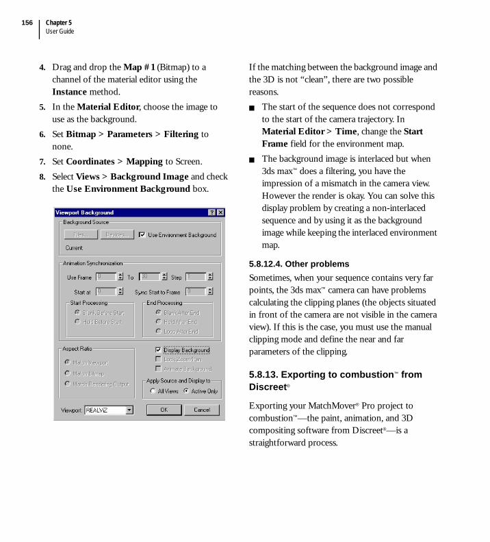
Chapter 5User Guide
156
4. Drag and drop the Map #1 (Bitmap) to a channel of the material editor using the Instance method.
5. In the Material Editor, choose the image to use as the background.
6. Set Bitmap > Parameters > Filtering to none.
7. Set Coordinates > Mapping to Screen.8. Select Views > Background Image and check
the Use Environment Background box.
If the matching between the background image and the 3D is not “clean”, there are two possible reasons.
The start of the sequence does not correspond to the start of the camera trajectory. In Material Editor > Time, change the Start Frame field for the environment map.The background image is interlaced but when 3ds max™ does a filtering, you have the impression of a mismatch in the camera view. However the render is okay. You can solve this display problem by creating a non-interlaced sequence and by using it as the background image while keeping the interlaced environment map.
5.8.12.4. Other problemsSometimes, when your sequence contains very far points, the 3ds max™ camera can have problems calculating the clipping planes (the objects situated in front of the camera are not visible in the camera view). If this is the case, you must use the manual clipping mode and define the near and far parameters of the clipping.
5.8.13. Exporting to combustion™ from Discreet®
Exporting your MatchMover® Pro project to combustion™—the paint, animation, and 3D compositing software from Discreet®—is a straightforward process.
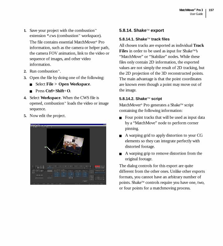
MatchMover® Pro 3User Guide
157
1. Save your project with the combustion™ extension *.cws (combustion™ workspace).The file contains essential MatchMover® Pro information, such as the camera or helper path, the camera FOV animation, link to the video or sequence of images, and other video information.
2. Run combustion™.3. Open the file by doing one of the following:
Select File > Open Workspace. Press Ctrl+Shift+O.
4. Select Workspace. When the CWS file is opened, combustion™ loads the video or image sequence.
5. Now edit the project.
5.8.14. ShakeTM export
5.8.14.1. ShakeTM track filesAll chosen tracks are exported as individual Track Files in order to be used as input for ShakeTM’s “MatchMove” or “Stabilize” nodes. While these files only contain 2D information, the exported values are not simply the result of 2D tracking, but the 2D projection of the 3D reconstructed points. The main advantage is that the point coordinates are known even though a point may move out of the image.
5.8.14.2. ShakeTM scriptMatchMover® Pro generates a ShakeTM script containing the following information:
Four point tracks that will be used as input data by a “MatchMove” node to perform corner pinning.A warping grid to apply distortion to your CG elements so they can integrate perfectly with distorted footage.A warping grip to remove distortion from the original footage.
The dialog controls for this export are quite different from the other ones. Unlike other exports formats, you cannot have an arbitrary number of points. ShakeTM controls require you have one, two, or four points for a matchmoving process.
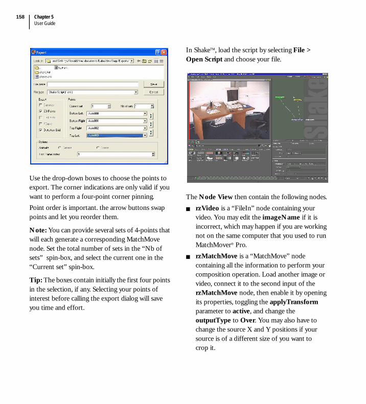
Chapter 5User Guide
158
Use the drop-down boxes to choose the points to export. The corner indications are only valid if you want to perform a four-point corner pinning.Point order is important. the arrow buttons swap points and let you reorder them.
Note: You can provide several sets of 4-points that will each generate a corresponding MatchMove node. Set the total number of sets in the “Nb of sets” spin-box, and select the current one in the “Current set” spin-box.
Tip: The boxes contain initially the first four points in the selection, if any. Selecting your points of interest before calling the export dialog will save you time and effort.
In ShakeTM, load the script by selecting File > Open Script and choose your file.
The Node View then contain the following nodes.rzVideo is a “FileIn” node containing your video. You may edit the imageName if it is incorrect, which may happen if you are working not on the same computer that you used to run MatchMover® Pro.rzMatchMove is a “MatchMove” node containing all the information to perform your composition operation. Load another image or video, connect it to the second input of the rzMatchMove node, then enable it by opening its properties, toggling the applyTransform parameter to active, and change the outputType to Over. You may also have to change the source X and Y positions if your source is of a different size of you want to crop it.

MatchMover® Pro 3User Guide
159
Note: If several sets of points have been provided, additional nodes will be numbered (e.g., rzMatchMover 2 …).
rzDistort is a “WarpX” node designed to apply distortion to any CG element before compositing it with your footage. If the latter has no distortion at all, this node is no use to you and you can delete it safely. rzUndistort is a “WarpX” node designed to remove the distortion from the original footage.
5.8.15. Cinema 4D export
Scenes exported by MatchMover® Pro can be read directly in Cinema4D; all points are exported as Null objects.Select File > Open and choose the *.c4d file exported by MatchMover.
Compositing with your footage requires some extra manipulations.1. Create a background object by selecting
Objects > Scene > Background.2. Open the Material Manager window and
create a new Material by selecting File > New Material.
3. Open the Material Editor by double-clicking on the newly created material.
4. Open the image browser by clicking on the Image button and choose your video file.
5. Press Edit to open the Time Controls.
6. Set the first frame, last frame and appropriate Frame Rate. Also set the Timing to Exact Frame.

Chapter 5User Guide
160
7. Add a Texture property to your Background Object.
8. Set it to the newly created material. Change the projection to Planar.
5.8.16. Inferno® export
MatchMover® Pro generates an Action setup that can be read by Discreet's Flint®, Flame®, and Inferno®.1. Open the Action module and choose your clips
for composition.
2. Select Setup > Load then choose the Action setup exported by MatchMover® Pro. All points appear as individual helpers in the Perspective view.
Tip: Each point will have its own node in the Schematics view. Automatic tracking will generate hundreds of points which, without filtering, will quickly clutter your Schematics view. It is therefore recommended to select the points of interest and export these only (see “Reconstructing 3D points for export” on page 144).

A
Glossary


MatchMover® Pro 3User Guide
163
Glossary
When working with MatchMover® Pro you have to understand a few of the basic key concepts from the worlds of 2D and 3D.Angle – Field of view (FOV) in degrees. 30 corresponds to the normal lens of 35 mm still camera. Antialiasing – Antialiasing is sub pixel interpolation, a technique that makes edges appear to have better resolution. Antialiasing is process to render an image at a higher resolution than the screen can display (typically two to four times higher linear resolution). This high-resolution result is then filtered down to the screen resolution, eliminating most visible rendering errors.Cache – A block of memory, generally of fixed size, that is used to store data loaded from the hard disk. Reading data from cache memory speeds up processing as it is faster than reading data from disk.Dolly – Moves the camera along the line of sight, i.e. close and far from the target. Term originally refers to the carriage under the camera stand, pushed on wheels along rails. Film Back – Value that represents the size of your film.FOV – Field of view.Interlace – Division of video frames into halves (odd and even), or fields, increase the frame rate without increasing the needed bandwidth.
Motion blur – A method of blurring images to create the effect of speed and movement.Occlusion – The effect of one object in 3D space blocking another object from view.Pan – Rotates the camera along vertical axis, that is, moving camera target sideways. Parallax – Changes the perspective between two adjacent pictures caused by the camera position changing between shots.Pixels – Array of picture elements, usually consisting of red, green, and blue color values, each with five to sixteen bits of precision.Rendering – The process used by MatchMover® to create images from the data files.Rendering algorithms – Algorithms that create images from models.Rendering Engine – Generically applies to the part of the graphics engine that draws 3D primitives, usually triangles or other simple polygons. In most implementations, the rendering engine is responsible for interpolation of edges and ‘filling in’ the triangle.Rendering packages – programs that implement rendering algorithmsRGB – Red-green-blue color models.Roll – Rotates the camera along the line of sight. If animated, a swaying effect is achieved. Scene – Defined by a data structure known as the scene database.

AppendixGlossary
164
Scene database – Database which provides a mathematical representation of the virtual objects in the scene and their position relative to each other.Scene management – The process of updating the scene database definitions as objects move or change.Scene space or world space – The coordinate system of a scene.Screen space – The 2D coordinates of pixels on the display device plus a third coordinate that defines the distance from the view point.Sub-pixel accuracy - A method of estimating movement to the nearest 1/5th of a pixel rather than one pixel. Tilt – Rotates the camera along the axis perpendicular to the line of sight, i.e moving target vertically. If animated, a nodding effect is achieved.
Transformation – Change of coordinates; a series of mathematical operations that act on output primitives and geometric attributes to convert them from modeling coordinates to device coordinates.Track – A track is anything that is animated over time. In MatchMover® Pro, these are the point tracksVector – Segment showing the displacement of a given pixel from one frame to the next one.View point – A virtual camera (analogous to the position of the camera in photography).Z values – (x, y) distance values.Zoom – Changes the field of view.
Channel selection button to help optimize 2D tracking shown in the bottom left corner that toggles display of a single color channel. Clicking on it cycles through RGB, R, G, B, and Alpha, when available.

Index
MatchMover® Pro 3User Guide
165
Index
Numerics2D
Modebutton ............................................................. 43
tracking, automatic........................................... 79tracking, supervised.......................................... 83
2D tracksautomatically generated ...................................81creating new tracks........................................... 83customizing the display of .............................. 45
2D Viewbutton................................................................. 32changing the time............................................. 46displaying the attributes.............................45, 46freezing the time............................................... 46navigation .......................................................... 47
3DMode ..................................................................48
button ............................................................. 43objects ................................................................ 16
3D View3D Helpers ........................................................ 50button................................................................. 32changing the Grid Step value ......................... 50displaying the attributes...................................49locking on the camera......................................50navigation .......................................................... 51wireframe divisions .......................................... 49
Aabout this guide ......................................................... 5
accessingsequence information ......................................69the online Help ...................................................5the Tech Center ..................................................6the Technical Support........................................6the Track Status Window options .................56the tutorials..........................................................5
Actions stacking .........................................42, 43, 57adding
frames to a constraint ....................................117keyframes to contours .....................................76keys to a curve.................................................134
aligning the manipulators’ pivot..........................138Auto Match Key......................................................89automatic 2D tracking ............................................15
refining the results............................................81running...............................................................79viewing the results ............................................81
Bbookmarks
deleting...............................................................70inserting..............................................................69moving ...............................................................70
browsing the footage ..............................................51
CCache Manager ........................................................66cache size, setting ....................................................66camera
constraints ................................................ 17, 116creating a new .................................................104
Index166
deleting............................................................. 108locking on in the 3D View.............................. 50turning toward the selected item ................... 51
camera computation............................................... 16camera parameters .................................................. 14camera solver
running............................................................. 121setting frames to solve................................... 121
centering the view on the selected item .............. 47changing
the 3D Grid Step value ................................... 50the color of
3D points ....................................................... 50camera paths.................................................. 49cameras .......................................................... 49key points on a Track Path ......................... 46lights ............................................................. 141relations........................................................ 114the 2D View background ............................ 45the 3D View background ............................ 49the Coordinate System Manipulator axes111the manipulators ......................................... 137the mesh....................................................... 140the Track Path............................................... 46the Tracking Tool......................................... 86
the current frame using the Numeric Field.. 58the current time using the Slider.................... 58the Grid Step value .......................................... 50the key frame default settings....................... 101the number of wireframe divisions ............... 49the size of the 3D Helpers.............................. 50the time in the 2D View.................................. 46the viewport layout .......................................... 44
Channel Selection ................................................. 164cleaning up tracks ................................................... 82
clearingcomputed 2D points........................................96keys .....................................................................88
computed 2D points.........................................95, 96configuring the tracker ...........................................92constraint
adding frames to.............................................117creating and enabling .....................................116deleting.............................................................118deleting frames from......................................118
contextual menuaccessing ............................................................61
a track’s properties .......................................84the Track Status Windowoptions...............56
addinga bookmark....................................................69a coordinate system....................................110a focal length constraint ............................116a keyframe......................................................76a light ............................................................141a post filter...................................................132a relation.......................................................113frames to a constraint ................................117keys to a curve.............................................134
centering the view on the selected item........47clearing
computed points...........................................96keys .................................................................88
copying a contour.............................................78creating
a new camera...............................................104a new track.....................................................83
deletinga bookmark....................................................70a camera .......................................................108

MatchMover® Pro 3User Guide
167
a constraint ..................................................118a contour ........................................................ 76a coordinate system....................................112a keyframe...................................................... 77a matte ............................................................ 72a relation.......................................................114a sequence...................................................... 69an object.......................................................136keys from a curve .......................................134
displayingthe 2D View attributes................................. 46the 3D View attributes................................. 49
duplicating a contour ....................................... 79editing
a key point type............................................. 87a pivot...........................................................138reference and key frames...........................103
ending a Work Area ......................................... 59freeing graph tangents ...................................133freezing the time............................................... 47generating a track automatically ..................... 81importing a scene ...........................................136initializing frames ...........................................102inverting a matte sequence.............................. 72loading
sequences ....................................................... 67locking
on the camera................................................ 50the camera on a track ...................................94the grid axes.................................................130
merging tracks................................................... 85modifying a bookmark’s position .................. 70pasting a contour.............................................. 78reconstructing a point in 3D ........................145removing frames from a constraint.............118
resetting a curve..............................................134resizing
the Graph Editor graph .............................129the Track Status graph .................................56
returningto the original zoom .....................................48to the start of the sequence .........................46
runningthe camera solver ........................................121the tracker bidirectional ...............................95the tracker forward or backward ................95
selecting a manipulator ..................................137setting
frames to solve ............................................121the largest zoom in a viewport ...................48the world reference.....................................112
showingand hiding the original curve ....................133the grid .........................................................130
starting a Work Area ........................................59toggling a constraint.......................................117turning the camera toward the selected item51
Contour Edition Mode...........................................73contours ....................................................................78
adding a keyframe.............................................76creating...............................................................73deleting...............................................................76
a keyframe......................................................77duplicating .........................................................79editing.................................................................77renaming ............................................................75selecting..............................................................74
coordinate systemcentering on a camera ....................................112defining using the Parameters Window ......109

Index168
deleting............................................................. 112manipulator ..................................................... 111
locking the axes of...................................... 111creating
a contour ........................................................... 73a new camera .................................................. 104a new light ....................................................... 140a new track ........................................................ 83and enabling a constraint .............................. 116
curvesadding keys to ................................................. 134deleting keys from.......................................... 134editing tangents .............................................. 133manual edition of ........................................... 132resetting ........................................................... 134smoothing using post filters ......................... 130
Ddeleting
3D primitives and objects.............................136a bookmark ....................................................... 70a camera........................................................... 108a constraint......................................................118a contour ........................................................... 76a coordinate system ....................................... 112a key ................................................................... 88a keyframe ......................................................... 77a relation .......................................................... 114a sequence ......................................................... 69frames
from a constraint ........................................ 118keys from a curve ........................................... 134point tracks ....................................................... 85
Display Toolbar....................................................... 43
displayingmattes .................................................................72relation planes .................................................114the 2D View attributes ....................................46the 3D View attributes ....................................49
drawing mattes.........................................................73
Eediting
3D primitives and objects .............................136a curve manually .............................................132a key point type.................................................87a light................................................................141contours .............................................................77curve tangents .................................................133reference and keyframes................................102
elasticssetting survey points ......................................115
exportinga project ...........................................................145Cinema4D .......................................................159combustion™ from Discreet .......................156file formats ......................................................144Inferno® ...........................................................160REALVIZ Ascii Camera 3D Tracks...........145REALVIZ Ascii Point Tracks......................147reconstructing 3D points for........................144to LightWave 3D™ .......................................152to MAXScript ........................................ 154, 157to Maya®...........................................................148to SOFTIMAGE®|3D..................................150to SOFTIMAGE®|XSI™ ............................151
MatchMover® Pro 3User Guide
169
Ffile formats
exporting..........................................................144importing .........................................................143motion control................................................119
file mask naming convention ................................ 68flushing the cache ................................................... 66footage ...................................................................... 11
importing ........................................................... 66frame rate ................................................................. 13frame rate, setting.................................................... 67frames
key.....................................................................100Free Camera mode.................................................. 50freezing the time...................................................... 46Full mode ................................................................. 41full screen, toggling................................................. 44
Ggetting help................................................................. 5Graded Ruler, description......................................54Graph Editor Window
locking the grid axes ......................................130resizing the graph ...........................................129toolbar..............................................................129
Grid Step, changing the value of .......................... 50
Hhelp
online Help.......................................................... 5Tech Center......................................................... 6Technical Support .............................................. 6tutorials ................................................................ 5
helper images ...........................................................11loading................................................................68
hidden tracks............................................................53horizontal zooming.................................................55
Iicons
2D Mode............................................................432D VIew button ...............................................323D Mode............................................................433D View button................................................32Align Mesh ......................................................140channel selection ............................................164Clean up tracks .................................................82Fit to Viewport .................................................48for adding new primitives .............................136for changing the viewport layout ...................44Freeze Time.......................................................47Full Screen .........................................................44Help ......................................................................5Light .................................................................140Lock on Camera ...............................................50Lock On Track .................................................94Locked................................................................96Motion Control Import .................................119Navigator ...........................................................47New
Bookmark ......................................................69Contour ..........................................................73Project ............................................................65Track...............................................................83
Open...................................................................65Orient Pivot.....................................................139Pan ......................................................................47Project Tree.......................................................83

Index170
Recompute ......................................................134Redo ................................................................... 43Run the Automatic Tracking....................23, 79Run/Stop
Camera Solving........................................... 121Track Backward............................................ 95Track Bidirectional ....................................... 95Track Forward .............................................. 95
scroll buttons .................................................... 47Skip Untracked ................................................. 97Smooth a time range...................................... 132Tech Center ........................................................ 6Time range
to linear ........................................................ 132to spline........................................................ 132
Undo .................................................................. 43image plane display, toggling................................. 48importing
3D objects ....................................................... 136files ................................................................... 143footage ............................................................... 66motion control data ....................................... 118
improvements in MatchMover® Pro 3 .................. 3installing MatchMover® Pro .................................... 6interface
description......................................................... 41Full mode .......................................................... 41Light mode........................................................ 41Project Window................................................ 52Time Line ........................................................ 127Track Window.................................................. 58
inverting selected tracks......................................... 85
Kkey frames ..............................................................100key points
editing.................................................................87moving ...............................................................88placing strategy .................................................89setting the parameters......................................90
of a single point ............................................91keyboard shortcuts..................................................61
default ................................................................61user-defined shortcuts .....................................61
keyframes..................................................................17and contours .....................................................76editing...............................................................102
Llicensing ...................................................................... 7Light mode...............................................................41Light Toolbar...........................................................42lights
creating.............................................................140editing...............................................................141
loadinghelper images ....................................................68mattes .................................................................70sequences...........................................................67
loading a sequence ..................................................67Lock on Camera mode...........................................50locking
on the camera in the 3D View .......................50the camera on a track.......................................94the grid axes ....................................................130tracks ..................................................................96
looping a sequence..................................................52
MatchMover® Pro 3User Guide
171
MMagnifier
changing the behavior ..................................... 60fast refresh......................................................... 97Toolbox ............................................................. 60
Main Toolbar ........................................................... 42manipulators
aligning the pivot of.......................................138Alignment........................................................138General.............................................................137orienting the pivot of.....................................139Translate/Scale ...............................................137
mapping the coordinate system on a camera....112mattes........................................................................ 16
drawing .............................................................. 73setting the properties of .................................. 72toggling the display of ..................................... 72
merging tracks ......................................................... 85minimum system requirements............................... 6mobile tracks............................................................ 53motion control................................................ 17, 118moving a key point ................................................. 88multiselection of tracks .......................................... 85
Nnavigation
in the 2D View ................................................. 47in the 3D View ................................................. 51toolbar................................................................ 45
Oobject mapping ......................................................114objects
deleting.............................................................136editing...............................................................136
stacking ............................................................140viewing .............................................................136
online Help.................................................................5opening a project.....................................................65orientating the manipulators’ pivot ....................139
Ppadlock, Magnifier Wndow ...................................60Ping-Pong.................................................................52play modes................................................................52Play Sequence toolbar.............................................51point
labels ...................................................................45point tracks
creating a new ...................................................83deleting...............................................................85merging ..............................................................85selecting..............................................................85
post filters...............................................................130preferences
autocleaning tracked points ............................92automatic key insertion....................................93automatically merge tracks..............................86changing
the 3D Grid Step value ................................50the key frame default settings ...................101the Magnifier behavior.................................60the number of wireframe divisions ............49the size of non-physical objects................141the size of the 3D Helpers ..........................50the Toolbox size ...........................................60the Track Path length...................................45
configuring the tracker ....................................92defining the search distance precision...........94enabling the Auto Match Key permanently .89

Index172
limiting the number of key frames .............. 101predicting point positions in successive images ............................................. 93resetting ............................................................. 66setting
the graph smoothing strength .................. 132the image cache size..................................... 66the Key Frame Step value ......................... 101the number of pixels to nudge ................... 93the Quality Thresholds ................................ 94the Tracking Tool’s pattern size................. 93the Tracking Tool’s search size .................. 93the up axis.................................................... 144
togglingautomatic key placement ............................. 92the Auto Clean function.............................. 88the current time display ............................... 46
tracking high/low-contrast sequences .......... 92primitives
deleting............................................................. 136editing .............................................................. 136stacking ............................................................ 140viewing............................................................. 136
Project Window ...................................................... 52projects
exporting .........................................................145managing ........................................................... 65opening .............................................................. 65saving ................................................................. 65starting a new.................................................... 65
propertiesaccessing sequence information..................... 69bookmarks......................................................... 70camera parameters ......................................... 106changing the size of the Tracking Tool ........ 86
constraints .......................................................117coordinate system...........................................110cropping images................................................79defining
the coordinate system ................................109the Work Area...............................................59
mattes, setting ...................................................72modifying the position of a bookmark .........70relations............................................................113renaming a contour ..........................................75sequence.............................................................68setting the parameters of a single key point .................................................91survey points ...................................................115tracks ..................................................................84
Rrecomputing parameters ......................................134reconstructing 3D points for exporting.............144reference frames, editing......................................102refining the automatic 2D tracking results..........81relations ....................................................................17
creating.............................................................113deleting.............................................................114displaying in the 3D View.............................114
renaming a contour.................................................75rendering
a sequence........................................................141hidden points ..................................................142only visible 2D tracks ....................................142
resettingpreferences ........................................................66the Graph Editor curve.................................134the Work Area ..................................................59

MatchMover® Pro 3User Guide
173
resizingthe Graph Editor graph ................................129the Track Status graph..................................... 56viewports ........................................................... 44
runningthe automatic 2D tracking .............................. 79the camera solver............................................121the tracker
forward or backward.................................... 94in bidirectional mode ...................................95
Ssaving a project........................................................ 65selecting
a Play Mode....................................................... 52point tracks........................................................ 85points and contours ......................................... 74
sequenceaccessing information ......................................69deleting...............................................................69loading................................................................ 67returning to the start ........................................ 46
sequences, switching between............................... 69setting
frames to solve................................................121key point parameters........................................ 90
of a single key point ..................................... 91matte properties................................................ 72the current time ................................................ 46the frame rate.................................................... 67the image cache size......................................... 66the largest zoom in a viewport....................... 48the world reference ........................................112
skippingunsolved tracks .................................................97untracked frames ..............................................96
smoothing a curve using post filters ..................130stacking objects......................................................140starting a new project..............................................65Status Bar..................................................................42supervised tracking........................................... 15, 83survey points ...........................................17, 114, 136
setting using elastics .......................................115Survey View ...........................................................124switching between sequence..................................69
TTech Center................................................................6Technical Support .....................................................6Time Line ...............................................................127
changingthe current frame using the Numeric Field58the current time using the Slider ................58
Work Area .........................................................58toggling
a constraint ......................................................117between the 2D and 3D modes .....................43between the 2D and 3D views .......................32the current time display ...................................46the display of mattes ........................................72the full screen....................................................44the Graph Editor grid....................................130
toolbarsDisplay ...............................................................43Graph Editor...................................................129Light ...................................................................42Main....................................................................42Navigation .........................................................45
Index174
Play Sequence ................................................... 51Tracking............................................................. 42
TrackStatus Window.................................................. 56Window .......................................................54, 55
trackmultiselection.................................................... 85paths................................................................... 45
trackerconfiguring ........................................................ 92running............................................................... 94
Tracking Tool .......................................................... 45changing the size of ......................................... 86description......................................................... 86
Tracking Toolbar .................................................... 42tracks
color display ...................................................... 96defining path color........................................... 45hidden ................................................................ 53inverting the selection ..................................... 85mobile ................................................................ 53
troubleshootingautomatic 2D tracking................................... 125the tracker.......................................................... 97
tutorials....................................................................... 5basic.................................................................... 21object-based tracking....................................... 34supervised tracking .......................................... 26
type conventions ....................................................... 5
UUndo ......................................................................... 43uninstalling MatchMover® Pro................................ 6
Vviewing
3D primitives and objects .............................136viewports
changing the layout ..........................................44resizing ...............................................................44
viewsSurvey...............................................................124
Wwireframe divisions, changing the number of ....49Work Area
description.........................................................58ending.................................................................59resetting..............................................................59starting ...............................................................59
Workspace................................................................43changing the viewport layout .........................44
world reference, setting........................................112
Zzooming
fitting to a viewport .........................................48Magnifier Window ...........................................60returning to the original ..................................48Track Window ..................................................55