master thesis- abraham fernández
TRANSCRIPT
Protections substitution for 6,3 kV machines in “Soto de Ribera” thermal plant.
by Abraham Fernández García
Submitted to the Department of Electrical Engineering, Electronics,
Computers and Systems in partial fulfillment of the requirements for the degree of
Master of Science in Electrical Energy Conversion and Power Systems at the
UNIVERSIDAD DE OVIEDO July 2013
© Universidad de Oviedo 2013. All rights reserved.
Author . . . . . . . . . . . . . . . . . . . . . . . . . . . . . . . . . . . . . . . . . . . . . . . . . .
. . Abraham Fernández García. E-mail: [email protected]
Certified by. . . . . . . . . . . . . . . . . . . . . . . . . . . . . . . . . . . . . . . . . . . . . . .
. . Pablo Arboleya Arboleya Associate Professor
Thesis Advisor
Certified by. . . . . . . . . . . . . . . . . . . . . . . . . . . . . . . . . . . . . . . . . . . . . . . . . Pablo Díaz Álvarez
Chief of Energy production at “Soto” power station EDP Thesis Co-Advisor
1

Protections substitution for 6,3 kV machines in “Soto de Ribera” thermal plant.
by
Fernández García, Abraham
Submitted to the Department of Electrical Engineering, Electronics, Computers and Systems
on July 22, 2013, in partial fulfillment of the requirements for the degree of
Master of Science in Electrical Energy Conversion and Power Systems
Abstract
New technologies implementation is a must for competing in the electrical sector and generator aren’t an exception .This thesis has been developed based on the need of changing the old protections in “Soto de Ribera” in order to improve the efficiency and control of protection system. This thesis has two completely different parts. A technical part, as the thermal cycles within or electrical system in the power plant. Inside this part there is well defined all the 6,3 kV machines included in the project as well as their protection relays , how they work, the setting values,etc…..The economical part focuses on financial aspects as the economical situation of suppliers or the detailed study about the costs present in the project. Keywords , Thermal cycles, 6,3 kV machines, protection relays. Thesis Advisor: Pablo Arboleya Arboleya Title: Associate Professor Thesis Co-Advisor: Pablo Díaz Álvarez Title: Chief of Energy production at “Soto” power station, EDP.
2

Acknowledgments
I would like to express my greatest appreciation to all those who helped with my problems. Special thanks to my Supervisor Pablo Arboleya for the useful information, and its implication during all course.
Furthermore, I would like to especially thank the entire team of the thermal plant of “Soto” for their dedication, nurturing this thesis with their experience, helping me throughout all the project.
And last but not least, I would like to thank my family, specially my parents, who
have always supported me in good and bad moments, being there always for assisting me, without asking anything in return.
3

Index 1 INTRODUCTION ................................................................................................................... 14
1.1 Objectives of the Master Thesis .................................................................................. 14
1.2 Electrical system history .............................................................................................. 14
1.2.1 The new electrical situation ................................................................................ 15
1.3 Power plant description .............................................................................................. 15
1.3.1 Power plants classification .................................................................................. 16
1.4 Electrical protections ................................................................................................... 16
1.4.1 Historical review .................................................................................................. 17
1.5 Most important electrical protection suppliers .......................................................... 17
1.5.1 Alstom Power ...................................................................................................... 18
1.5.2 ABB ...................................................................................................................... 18
1.5.3 Schneider Electric ................................................................................................ 19
1.5.4 Financial comparison ........................................................................................... 21
1.5.5 AREVA acquisition ............................................................................................... 23
1.6 HC company ................................................................................................................ 24
2 “SOTO DE RIBERA” POWER STATION. ................................................................................. 25
2.1.1 Soto 1 .................................................................................................................. 25
2.1.2 Soto 2 .................................................................................................................. 25
2.1.3 Soto 3 .................................................................................................................. 25
2.2 General description for SOTO 3 .................................................................................. 26
2.2.1 Water-steam cycle .............................................................................................. 27
2.2.2 Air cycle / coaling stage ....................................................................................... 30
2.2.3 Secondary air cycle .............................................................................................. 31
2.2.4 Ash and slag removing ........................................................................................ 31
2.2.5 Combustion stage ................................................................................................ 31
2.2.6 Cooling system .................................................................................................... 32
3 DESCRIPTION ABOUT THE ELECTRICAL SYSTEM IN “SOTO 3”. ............................................ 33
3.1 Emergency power supply ............................................................................................ 33
3.2 Generation group transformer (TG) ............................................................................ 34
3.3 Ancillary services transformer (TSA) ........................................................................... 35
3.3.1 Main characteristics ............................................................................................ 36
3.4 Commutator between the TSA and the TG ................................................................. 37
3.5 Internal electrical distribution ..................................................................................... 37
4

3.6 6,3 kV system .............................................................................................................. 38
3.7 Grounding system ....................................................................................................... 39
3.8 Existing protection in the cabins ................................................................................. 42
4 PREVIOUS PROTECTION SYSTEMS DESCRIPTION ................................................................ 43
4.1 IAC RELAYS................................................................................................................... 43
4.1.1 Time dependent operating curve ........................................................................ 44
4.1.2 Motor protection................................................................................................. 44
4.1.3 Transformers protection ..................................................................................... 44
4.1.4 Instantaneous Unit .............................................................................................. 44
4.2 PJC RELAYS................................................................................................................... 44
4.2.1 Relay Characteristics ........................................................................................... 45
4.3 Summary of protection functions ............................................................................... 46
4.3.1 Setting values ...................................................................................................... 46
4.3.2 Curves used for defining time characteristics ..................................................... 48
5 Budget Request ................................................................................................................... 50
5.1 Emplacement and equipment description .................................................................. 50
5.2 Scope of the Project .................................................................................................... 50
5.2.1 Documentation: .................................................................................................. 51
5.2.2 General conditions: ............................................................................................. 51
5.2.3 Communication and engineering: ....................................................................... 51
5.2.4 Mounting ............................................................................................................. 51
5.2.5 Factory Acceptance Test (FAT) tests ................................................................... 51
5.2.6 Spare parts .......................................................................................................... 51
5.2.7 Training Course ................................................................................................... 51
5.3 Conditions of the project ............................................................................................ 52
5.4 Annexes ....................................................................................................................... 52
6 TENDER COMPARISOM ....................................................................................................... 53
6.1 ABB .............................................................................................................................. 53
6.2 ALSTOM ....................................................................................................................... 53
6.3 SCHNEIDER .................................................................................................................. 53
6.3.1 Technical comparison .......................................................................................... 55
6.3.2 Economical comparison ...................................................................................... 57
7 TENDER SELECTION ............................................................................................................. 58
7.1 Technical conditions .................................................................................................... 58
5
7.1.1 Scope of the tender ............................................................................................. 59
7.1.2 Engineering .......................................................................................................... 59
7.1.3 Materials supply .................................................................................................. 59
7.1.4 Mounting ............................................................................................................. 59
7.1.5 General description for the offer ........................................................................ 60
7.2 Economical conditions ................................................................................................ 60
8 NEW PROTECTION FUNCTIONS ........................................................................................... 62
8.1 Thermal imaging (49) .................................................................................................. 62
8.2 Reverse phase (46) ...................................................................................................... 64
8.3 Excessive starting time / Rotor locking (48/51LR) ...................................................... 66
8.3.1 Excessive start time (48)...................................................................................... 67
8.3.2 Rotor locking (51LR) ............................................................................................ 68
8.4 Undervoltage protection ............................................................................................. 69
8.5 ABs-Anti back-spin protection (27 Abs) ...................................................................... 70
8.6 Startups limitation (66) ............................................................................................... 71
8.7 Undercurrent protection (37) ..................................................................................... 72
9 CONCLUSIONS ..................................................................................................................... 73
10 FUTURE DEVELOPMENTS ................................................................................................ 74
11 QUALITY REPORT ............................................................................................................. 75
12 BIBLIOGRAPHY ................................................................................................................. 76
ANNEXES ..................................................................................................................................... 77
13.1 Annex 1: 6,3 KV motors technical data. ...................................................................... 78
In this annex, all the motors belonging the project will be described in more detailed, for a better understanding. In that description all the technical information as well as main functions will be defined for each motor. ................................................................................... 78
13.1.1 Feedwater pumps ............................................................................................... 79
13.1.2 Condensate pump ............................................................................................... 80
13.1.3 Circulating pump ................................................................................................. 81
13.1.4 Boiler recirculation pump .................................................................................... 82
13.1.5 Grinder ................................................................................................................ 83
13.1.6 Primary air fan ..................................................................................................... 84
13.1.7 Induced draft fan ................................................................................................. 85
13.1.8 Forced draft fan ................................................................................................... 86
13.1.9 High pressure pump ............................................................................................ 87
13.1.10 Blower ................................................................................................................. 88
6

7

List of Figures Figure 1 : Power plant classification ........................................................................................... 16
Figure 2: Basic thermal cycles .................................................................................................... 26
Figure 3 : Water Steam Cycle ..................................................................................................... 27
Figure 4 Reboiler Cycle ............................................................................................................... 30
Figure 5 Boiler Description ......................................................................................................... 32
Figure 6 Diesel Generator .......................................................................................................... 33
Figure 7 C.C. Batteries ................................................................................................................ 34
Figure 8 TG Single Wire Description ........................................................................................... 35
Figure 9: TSA Single Wire Description ........................................................................................ 36
Figure 10: Internal Electrical Distribution .................................................................................. 37
Figure 11: Grounding System ..................................................................................................... 39
Figure 12: PSIM Simulation ........................................................................................................ 40
Figure 13: Load currents without ground failure ....................................................................... 40
Figure 14: Voltage in the secondary of the transformer ............................................................ 41
Figure 15: Load current when fault occurs ................................................................................ 41
Figure 16: Voltage in the secondary of the transformer ............................................................ 41
Figure 17: Cabin topologies ........................................................................................................ 43
Figure 18: Differential protections ............................................................................................. 45
Figure 19: Setting example ......................................................................................................... 47
Figure 20: IAC51 curve setting ................................................................................................... 48
Figure 21: IAC66 Curves ............................................................................................................. 49
Figure 22 :Thermal protection curve .......................................................................................... 64
Figure 23 : Direct and inverse equivalent circuits ..................................................................... 64
Figure 24: Excessive start time setting ....................................................................................... 68
Figure 25 Excessive start-up protection curve ........................................................................... 69
Figure 26 : Start-ups limitation ................................................................................................... 71
Figure 27 : Starting cycles guidelines ......................................................................................... 72
Figure 28 : Feedwater pump ...................................................................................................... 79
8

Figure 29 : Condensate pump ................................................................................................... 80
Figure 30 : Circulating Pum ........................................................................................................ 81
Figure 31: Boiler recirculation pump .......................................................................................... 82
Figure 32 : Grinder...................................................................................................................... 83
Figure 33 : Primary air fan .......................................................................................................... 84
Figure 34: Induced draft fan ....................................................................................................... 85
Figure 35 :Forced draft fan ......................................................................................................... 86
Figure 36 : High pressure pump ................................................................................................. 87
Figure 37 : Blower ...................................................................................................................... 88
9

List of Tables TABLE 1: Financial information .................................................................................................. 21
TABLE 2 Pressure Conditions in Feed Water System ................................................................. 29
TABLE 3 TG characteristics ......................................................................................................... 34
TABLE 4: TSA Charachterics ........................................................................................................ 36
TABLE 5: 6,3 kV Machines .......................................................................................................... 38
TABLE 6: Summary of protection functions ............................................................................... 46
TABLE 7: Tender Comparison ..................................................................................................... 54
TABLE 8: Economical comparison ............................................................................................... 57
TABLE 9 : VAMP relay characteristics ......................................................................................... 59
TABLE 10 : Final economical offer .............................................................................................. 61
TABLE 11 Parameters for thermal imaging protection .............................................................. 63
TABLE 12: Feed water pump technical data ............................................................................... 79
TABLE 13 : Condensate pump technical data ............................................................................. 80
TABLE 14 : Circulating pump technical data ............................................................................... 81
TABLE 15: Boiler recirculation pump technical data .................................................................. 82
TABLE 16 : Grinder Technical data ............................................................................................. 83
TABLE 17 : Primary air fan Technical data .................................................................................. 84
TABLE 18 : Induced draft fan Technical data .............................................................................. 85
TABLE 19 : Forced draft fan technical data ................................................................................ 86
TABLE 20 : High pressure pump technical data .......................................................................... 87
TABLE 21 : Blower technical data ............................................................................................... 88
10

11
Table of Symbols
Acronyms
AC Alternating Current.
DC Direct Current.
WWI,WWII World war I/II.
CLD Central load dispatcher
ALSTOM Alstom power S.A
ABB Asea Brow Bovery S.A.
EDP Energías de Portugal
ROE Return On Equity
HC HidroCantábrico
PSIM Power Simulator
12

13

1 INTRODUCTION
1.1 Objectives of the Master Thesis The objectives of this work are the following:
• Analyze the operation of a coal thermal powered station. • Identify the 6,3 kV machines that participate in the process. • Elaborate a budget request for substituting the protection of 6,3 kV machines. • Analyze the tenders and selecting one of them ,considering technical as well as
economical aspects. • Arrange condition terms with the supplier.
1.2 Electrical system history The first practical application of electricity in Spain, dates back to 1852, when the pharmacist ‘Domenech’, in Barcelona, was able to use electrical lights in his establishment. From that day, the “light revolution” started in Spain. The development of electrical appliances was so important that in 1885, a preliminary law was passed for electrical applications. The huge new electrical industry that grew because of this law, brought the creation of many new companies in the final two decades of the 19th century. The first data about power generation in Spain appeared in 1901. This official information shows that there were 860 power stations, all of them being either thermal powered (61%) or hydro powered (39%). The emergence of alternating current (AC) in the beginning of 20th century let to a radical change in electrical generation policy. As a result, in 1929 the installed power increased 12 times with respect to 1901, hydropower making up 81 % of the total generation[1]. With the New York stock market crash in 1929, together with the Spanish civil war and WWII, Spain fell into a major economic downturn. In this situation, the government imposed energy selling price, together with high inflation, meant that private energy producing companies, started to have many economic difficulties. All these factors resulted in the most critical energy deficit situation up until that time. With the investment of public money and the improvements of producing systems, the recently created public energy companies (ENDESA, ENHER, etc), solved most of the energy deficit, making the whole system more stable. Moreover, up to 1950, the energy system was so regional, each region had its own generation network, having a highly
14
disperse production system. In 1953, the CLD (Central Load Dispatcher) was created, to organize the national electricity production, and make the whole system more stable. From the 1950s price restrictions disappeared, and the energy sector started to grow quickly. This growth was so strong, that, the installed capacity tripled from 1960 to 1970. In 1968 nuclear powered generation began, with the power station of “Zorita”. In 1970, due to the rapid growth of the energy sector, the first national electrical plan was imposed. Included in this plan, was how and when to build more generation centres. As the prices of crude oil fluctuated greatly in this decade, the plan was adapted to favour the creation of coal power plants. The most important developments of the 1980s in the Spanish energy industry were the creation of five nuclear power plants, and the implementation of the first pumping stations, the latter which allowed the storage of some generated energy into a potential form.
1.2.1 The new electrical situation In 1996 the Council of the European Union adopted the “Directive on Common Rules for the Internal Electricity Market”, which contains clear objectives and minimum standards of liberalization introducing more competence in the European electricity market. Due to this, on January 1, 1998 Spain introduced major regulatory changes in the energy sector by passing the law 54/1997 . The main characteristics of this new law resulted in:
• Generation, commercialization and international energy exchanges becoming competitive markets from then on.
• The transport and distribution of energy becoming monopolies. • The creation of 2 new public organizations, the market operators and the
system operators. These organizations were created to help control the new economic framework.
This law is currently in effect with certain modifications. From 1996 to 2008 the power system grew rapidly and resulted in stable situation. With the crisis in 2008, the energy sector has stalled, even decreasing the energy demand these past years.
1.3 Power plant description A power plant is assembly of systems or subsystems to generate electricity, i.e., power with economy and requirements. The power plant itself must be useful economically and as environmental friendly as possible to society [2].
15

1.3.1 Power plants classification
Figure 1 : Power plant classification
A power plant may also be defined as a machine or assembly of equipment that generates and delivers a flow of mechanical or electrical energy. The main equipment for the generation of electric power is generator. When coupling the generator to a prime mover electricity is generated. The type of prime mover determines the type of power plant. [2].
1.4 Electrical protections
Each type of power plant, needs to assure it will be secure, and the use of electrical protections are mandatory. They continuously monitor the safe function of the plant, by cutting the energy production, for example by triggering a circuit breaker, when disturbances such as short-circuits, insulation faults, etc, appear. Selecting a good protection device is not an easy decision, but is one of the most important factors, when designing the electrical system. The main functions are:
• The protection of people against electrical Hazards. • The Prevention of damage to the equipment (a 3 phase short-circuit in a
medium voltage busbar, can melt 50 kg of copper in 1 second) • Voltages limitations • In some cases the protection of nearby installations.
To meet these objectives, a protection system must be fast and reliable.
16
The focus of this project is to determine the best new protection devices for the existing medium voltage machines, in the “SOTO DE RIBERA” power station.
1.4.1 Historical review The first electrical power system was built by “North America General Electric” company in 1878. The first protection devices date from the same time as this first electrical system [5]. Already in the first power plant, fuses appeared as protective elements. These devices are still used now because they are reliable and cheap, however they have some drawbacks, as they can’t determine where the fault appears, or the fact that if the fuse actuates once, the system can’t be restored, because after each operation the fuse must be replaced [5]. The next step was the development of electro-mechanical relays, having the advantages of controlling the operation times and the reclosing capability that enables to reuse the device even if a failure is mitigated. This relay technology has been used for around eighty years, and there are 3 clearly differentiated stages:
• Electromechanical relays. • Solid-state relays (electronic devices): the great advantage with respect to the
electromechanical devices is that they don’t have any moving parts, being more reliable, accurate, and having less maintenance.
• Digital relays (microprocessors): faster operation, less space and cheaper devices.
As well as the 3 different types of relays, at industrial level, this technology is growing into a fourth, combining the protective function with the measurement function, and the communication with other systems, for improving the flexibility of the device with respect to the whole system [6].
1.5 Most important electrical protection suppliers
There are several electrical companies which have departments for electrical protections. Even so, in this section there is a brief description about the main suppliers for this project, which are Alstom Power (ALSTOM) , Asea Brown Boveri (ABB) and Schneider Electric.
17

1.5.1 Alstom Power A French company, founded in 1928. Alstom is one of the most important electrical companies worldwide. It has operations in 70 countries, electrical generation (power plant equipment) and high-speed train technology being their basic business areas. Nowadays they are performing projects in many countries, including: China :
• x 600 MW = 2400 MW (Steam power plant) Germany :
• 912 MW (Coal steam power plant ) • 2x 1100 MW = 2200 MW (Steam power plant)
South Africa: • x 800 MW = 4800 MW (Supercritical full turbine) • x 800 MW = 4800 MW (Coal steam turbine)
The first time that ALSTOM appeared was in 1864, constructing subassemblies for rolling train stock. From then on, as technology evolved, the company decided to expand its activities, making acquisitions, increasing the flexibility of the whole group. They changed their main business activities and they are now much more focused on energy production and distribution, compared to their previous activities [7]. Even so, ALSTOM did not have a specific division related to protections, until the acquisition of AREVA in 2008 (Joint venture with Schneider electric S.A.). Since that Joint Venture, there is a new division inside the group called Alstom Grid (created in 2010), which is focused on electrical protections. This new division, has an advantage for making the project related above, they have been already developed a similar project in “Aboño” power station. This power plant is owned by EDP group, so they have so good references for doing any work on the power station. Having good references is an important factor when deciding the final provider of whatever project. That’s the reason why ALSTOM include this information within the first pages of the offer. From the acquisition of AREVA, ALSTOM started to offer MICOM protection relays. These relays can be used by Schneider, but for the tender ALSTOM offered MICOM series and Schneider offered VAMP series [8].
1.5.2 ABB The Company provides a range of products, systems, solutions and services. Its power businesses focus on power transmission, distribution and power-plant automation and serve electric, gas and water utilities, as well as industrial and commercial customers. Its automation businesses serve a range of industries with measurement, control, protection and process optimization applications. It operates in approximately 100
18

countries across four regions: Europe, the Americas, Asia, and the Middle East and Africa (MEA) [9]. The history of this company is basically the history of two different companies: The first started in 1891, when Charles E. L. Brown and Walter Boveri establish Brown, Boveri & Cie (BBC) in Baden, Switzerland. This new company focused on alternating current generators, supplying the first large-scale combined heat and power plant in AC in 1893. From then, they developed basically power stations technologies [9]. The second company started more or less at the same time, when two incipient companies, Elektriska Aktiebolaget and Wenströms & Granströms Elektriska Kraftbolag, merged together, in 1890, to form ASEA. From the beginning, this firm, focused on three-phase transmission systems, developing the first three-phase prototype in Sweden in 1893. By the early 1950s the main occupation of ASEA was the development of transport networks in DC and process automation. The paths of these two giants in the electricity sector crossed in 1988, when they merged to form ABB. Up to now ABB has earned $17 billion and employed 160,000 people around the world [9] . The most important projects they have been involved recently are their works in Sao Paulo and their efforts in the energy storage sector. Edgard de Souza substation – A principal node in the Sao Paulo power system that delivers electricity to a significant portion of the city. The substation is owned by CIA de Transmissao de Energia Eletrica Paulista (CTEEP). Recently CTEEP awarded ABB a contract to deliver an advanced automation, protection and control system for the substation to improve the reliability of power supplies in time for the start of the 2014 FIFA World Cup [10]. With the renewable energies quickly increasing, storage is becoming more and more important for balancing electricity needs and supplies. Thus far, pumped hydro storage has been the only viable solution for bulk storage, yet recent advances in battery technologies are now paving the way for battery-based storage solutions that enable the efficient integration of distributed and intermittent renewable power [10]. To support such efforts in southern Italy, ABB will provide Enel Distribuzione with a battery energy storage system that will enable the utility to study the benefits of using such facilities in their distribution network. The system will be installed at the Contrada Dirillo distribution substation in Ragusa province in southern Sicily. It can provide 2 megawatts (MW) of power for up 30 minutes and will be housed in three factory-tested containers – two containing lithium-ion batteries and a third accommodating the power conversion and energy management systems [11].
1.5.3 Schneider Electric As a global specialist in energy management with operations in more than 100 countries, Schneider Electric offers integrated solutions across multiple market segments, including leadership positions in Utilities & Infrastructure, Industries & Machines Manufacturers, Non-residential Building, Data Centres & Networks and in Residential.
19

Focused on making energy safe, reliable, efficient, productive and green, the Group's 140,000 plus employees achieved sales of 24 billion Euros in 2012, through an active commitment to help individuals and organizations make the most of their energy [12]. The origins of Schneider electric go back to 1836 when The Schneider brothers took over the Creusot foundries, creating a new company called Schneider and Cie. After that takeover, they focused on armament technology. When WWI arrived, they created cannon with as much quality as Krupp’s, which was the most successful at the time. As well as armament, they associated with Westinghouse, a major international electrical group. The Group enlarged its activities to manufacturing electrical motors, electrical equipment for power stations and electric locomotives [12]. Between WWI and WWII, the group’s business activities were diverse comprising of armament, hard equipment, electricity facilities… But after 1945, Schneider gradually abandoned armaments and turned to construction, iron, steel works and electricity. Since then the company has completely reorganised in order to diversify and open up to new markets.The company name changed to Groupe Schneider [12]. With the merger of Group Schneider, Telematique, and Merlin Gerin in 1994; added to the adquisition of Modicom in 1997, the group became one of the most important companies in the power sector. In May, 1999 the group was renamed as Schneider Electric S.A.
Despite being one of the largest electric companies in the world, Schneider Electric didn’t have a strong reputation in the electrical protections sector, but with the acquisition of AREVA in 2008, they improved their competitively in that sector [9].
Nowadays they have 3 series of protection relays, the SEPAM series is the first developed internally in Schneider. When they acquired AREVA they incorporated the MICOM series. Finally they have recently developed a new series called VAMP which is the one offered for this tender.
20
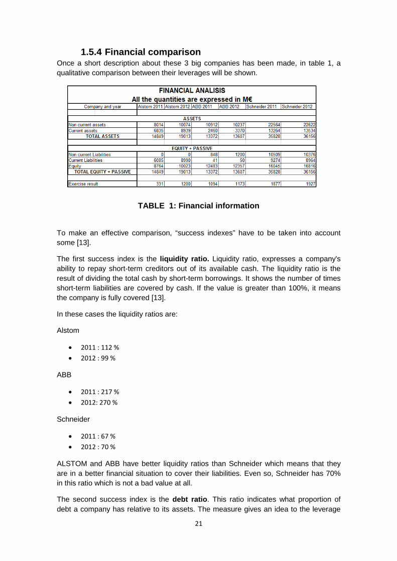
1.5.4 Financial comparison Once a short description about these 3 big companies has been made, in table 1, a qualitative comparison between their leverages will be shown.
TABLE 1: Financial information
To make an effective comparison, “success indexes” have to be taken into account some [13].
The first success index is the liquidity ratio. Liquidity ratio, expresses a company's ability to repay short-term creditors out of its available cash. The liquidity ratio is the result of dividing the total cash by short-term borrowings. It shows the number of times short-term liabilities are covered by cash. If the value is greater than 100%, it means the company is fully covered [13].
In these cases the liquidity ratios are:
Alstom
• 2011 : 112 %
• 2012 : 99 %
ABB
• 2011 : 217 %
• 2012: 270 %
Schneider
• 2011 : 67 %
• 2012 : 70 %
ALSTOM and ABB have better liquidity ratios than Schneider which means that they are in a better financial situation to cover their liabilities. Even so, Schneider has 70% in this ratio which is not a bad value at all.
The second success index is the debt ratio. This ratio indicates what proportion of debt a company has relative to its assets. The measure gives an idea to the leverage
21
of the company along with the potential risks the company faces in terms of its debt-load.
Good debt ratios are between 30-70 %, higher than 70 % normally means that the company is too much risky, and lower than 30 % normally means so conservative company[13].
For the companies these are the results:
Alstom
• 2011 : 41 %
• 2012 : 47 %
ABB
• 2011 : 0 %
• 2012: 0 %
Schneider
• 2011 : 26 %
• 2012 : 25 %
Despite Schneider has less than 30 % , both Alstom and Schneider results can be considered quite good, and it can be expected growth in the coming years. Moreover, ABB has a 0% debt ratio which is very conservative, which will probably result in a slow growth rate.
Another important ratio is the Return On Equity ratio (ROE) Return on equity measures a corporation's profitability by revealing how much profit a company generates with the money shareholders have invested.
A good ROE ratio is considered anywhere upwards of 10% [13].
The ratios are:
Alstom
• 2011 : 4 %
• 2012 : 12 %
ABB
• 2011 : 9 %
• 2012: 9 %
Schneider
• 2011 : 12 %
• 2012 : 11 %
22
ALSTOM has so quite variable ROE, being so low this ratio in 2011. The other 2 companies have so stable ROE that makes them more reliable attending to this.
The financial analisys for these companies is reflected in the following conclusions
ALSTOM has a good liquidity ratio which shows their actual financial situation is healthy. The debt ratio is stable, so the company is not too conservative or not assuming so many risks. The ROE has fluctuated sharply, which is not a good situation for the shareholders.
ABB has a high liquidity ratio, so they have too much cash without being invested. From the company view point this might be a good position to be in, for example when needing to invest in new technologies. The debt ratio is 0, which is very conservative value, from the view point of company growth. The 3rd ratio is lower than the other 2 companies, so investors are earning less money than in the other cases.
Schneider hasn’t got a good liquidity ratio, making the company a little unstable because if an unexpected situation appears, the company can’t cover the debts with the liquid cash. On the other hand, the other 2 ratios are optimal for growth, so probably the liquidity situation will improve in the following years.
These 3 companies have good ratios and a healthy financial situation, so in general terms the 3 are adequate for making business with.
1.5.5 AREVA acquisition Areva S.A. is a French public multinational industrial conglomerate headquartered in Courbevoie, Paris. Areva is mainly known for nuclear power, although it also pursues interests in other energy projects, like medium voltage protections.
Areva was created on 3 September 2001, by the merger of 3 companies: Framatome, Cogema and Technicatome. This company had a high public ownership ( French government). In 2010 the shareholders decided to sell the company as 2 feasible offers were on the table. On one hand the Japanese company Toshiba made the highest offer, however there was a joint offer from Schneider electric and ALSTOM. The joint venture of 2 national companies was much more beneficial for the French government as they wanted the company ownership to remain in France. So finally the company was acquired by the 2 most important energy companies in France, Schneider electric and ALSTOM, despite both Areva T&D management and workers opposing the sale to the Alstom-Schneider consortium as it mean breaking the third-largest supplier of transmission and distribution equipment in two less stable parts, with lower market value and more insecurity for the workers.
From then, Schneider took the medium-voltage distribution while ALSTOM took the high-tension transmission business.
In this agreement between the companies, despite Schneider acquiring the medium protection, there is a family of protection relays, more precisely the “MICOM Px4x” that remained shared for both companies.
23

1.6 HC company HC energy is company created in 1913, with the initial name of “Sociedad Civil Privada de Saltos de Agua de Somiedo”. In the beginnings, the first business area was the power production using water. Their first energy plant started operation in 1917. This first installation consisted of one hydro powered station taking water from the River “El valle” , a little substation in Oviedo, and then a transmission line to Gijón. This new company changed the name in 1920 when it changed into a public limited company. After that, they continued with hydro powered plants, for example the plant in “La Riera” built in 1930, or the plant in “Priañes” placed in Oviedo[16].
In August 1944 (in full autarky and in a critical period of the national economy) HC acquired "Company People's Gas and Electricity of Gijon", founded in 1901. This company had adquired some others energy companies in Aviles, Candas and Illas.
Thus, HC gained a lot of market share and installed capacity, becoming the most important energy company in Asturias[16].
Throughout this process of expansion, HC continued investing in new hydropower plants between 1942 and 1975. Although they started with Hydropower plants, they extended their business area, with some thermal plants from 1962, like “Soto de Ribera”, “Aboño” and “Castejon”. In 1968 HC took 15% shares in “Trillo” nuclear plant. In 2000 they built their first combined cycle thermal plant in “Castejon” (Navarra)[16].
From 1980 HC was not exempt from hostile attacks by other operators. Union Fenosa tried several times to gain the control of it. Between 1992 and 1993, the energy Galician-Madrid (which in 2008 was absorbed by the Catalan Natural Gas) acquired 8 % of the company [15].
The sale of “Banco Herrero” in 2000 to “Banco Sabadell”, a financial group without any interest in industrial applications, placed HC into a bad financial reference, with only “Cajastur” as the sole shareholder. This shareholding weakness was exploited in the market for national and international competitors, who initiated the acquisition attempt by Texas Utilities, an HC shareholder from 1998[15].
Apart from the offer from Texas Utilities, there were other 4 offers between 2001 and 2011:
• Union Fernosa. • Energie Baden-Württemberg (EnBW)/Ferroatlántica. • Rheinisch-Westfälisches also Elektrizitätswerk (RWE). • Energias de Portugal (EDP)-Cajastur.
The highest bid was from EnBW and Ferroatlántica, but the framework shielding of the company resulted in EDP-Cajastur acquiring the company. So finally in 2004 HC became a subsidiary of EDP[15].
24

2 “SOTO DE RIBERA” POWER STATION. The thermal power station of “Soto de Ribera” (CTSR), is an industrial installation focused on energy generation. It is just on the left side of the “Nalón” river, in the council of “Ribera de Arriba ” 7 kilometres away from the capital of Asturias. This location, was chosen because of the availability of a high flow rate from the river, and the proximity of the railway from which the fuel arrives.
The CTSR, was composed by 3 generation units, “Soto 1” (67 MW), “Soto 2” (254 MW) and “Soto 3” (350 MW). It is owned by “Energies from Portugal” (EDP).
2.1.1 Soto 1 Up to 1960, there were a good balance in asturian power plant energy production, having a good balance between thermal and hydropower. In 1960, the construction of some hydropower stations (“Salime, Doiras ampliation, Priañes, etc…”) showed the need for new thermal power station as well as for maintaining the balance and also use the mining resources available. As a response to this requirement, the construction of “Soto 1” started. This unit started the operation the 20th of May 1962.
In 2007 this unit halted the production, after more than 191.000 working hours and more than 11200 GWh generated.
2.1.2 Soto 2 At the end of 1963, the operation of the first group was so successful. This point, added to the increase of the demand in the area and the improvement in the railways ( electrical traction), advised to increase the installed power, springing the second generation group, “Soto 2”, which started operation on 28th of September 1967.
2.1.3 Soto 3 In 1977 the thermal energy technology was upgraded. Some boilers in Spain that could burn more types of carbon started to appear, with much better efficiencies than previous boilers. The improvement of the technology together with the strong increase in the mining of coal in Asturias, favoured the construction of Soto 3, which started to operate the 10th of August 1984. This generating group will be detailed in following paragraphs.
25

2.2 General description for SOTO 3 “Soto 3” is a self contained unit, which is composed by boiler-turbine-alternator. The maximum power that it can deliver is 350 MW, using a regenerative thermal cycle with steam extraction for 7 warmers, and a reheating stage.
There are 3 basic cycles inside this generation group:
• Water-steam cycle • Cooling cycle • Air cycle • Ash and slag elimination.
Figure 2 shows a block diagram, which describes the whole system.
Figure 2: Basic thermal cycles
There are 2 common points in these cycles, the condenser is a common point of cooling cycle and water-steam cycle, and the boiler belongs to 3 cycles: water-steam, air and ash and slag elimination cycles.
26
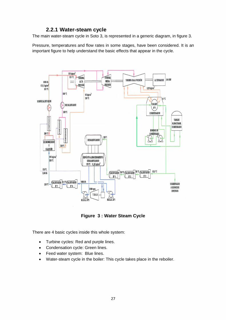
2.2.1 Water-steam cycle The main water-steam cycle in Soto 3, is represented in a generic diagram, in figure 3.
Pressure, temperatures and flow rates in some stages, have been considered. It is an important figure to help understand the basic effects that appear in the cycle.
Figure 3 : Water Steam Cycle
There are 4 basic cycles inside this whole system:
• Turbine cycles: Red and purple lines. • Condensation cycle: Green lines. • Feed water system: Blue lines. • Water-steam cycle in the boiler: This cycle takes place in the reboiler.
27

Turbine cycles The steam generated inside the boiler (175 kg/cm2; 540 ºC), enters into the high pressure zone of the turbine, and gives part of the stored energy, to the rotor of the turbine. Once the steam has lost part of the temperature and pressure in this process, it must be re-heated to reach the medium pressure turbine conditions (39 kg/cm2; 540 ºC). This medium pressure steam goes along the turbine, and passes directly to the low pressure zone which is the last power harnessing system. After that, the steam arrives to the water condenser. In rated conditions, there is an steam injection of 1048 ton/h at 170 kg/cm2, finally arriving to the condenser at 674 ton/h at 0,093 kg/cm2. This difference between flow rates gives an idea of what part has been consumed in the different stages of the turbine.
Condenser cycle The main function of this system is to raise the pressure and temperature of the water, obtained from the condenser, and bring it to the storage water tank. This system is composed by the following parts.
The condenser is basically a heat exchanger that collects all the steam from the low pressure parts of the turbine, and forces it to circulate outside the tubes that contains cooling water. This way, the steam loses temperature, and part of it turns into water. This water is temporally stored in the bottom of the condenser.
The condensate pumps extract the water collected in the condenser, and send it to the storage tank. This machine takes the water at 0,106 kg/cm2 and they elevate the pressure to 30 Kg/cm2.
The pumped water passes through 4 heaters to elevate the temperature.
Feed water system This system provides water to the boiler but taking into account the necessary conditions (quantity, pressure, temperature, chemical composition, etc). The storage water tank (degasser) provides water to the 3 feedwater pumps. These 3 machines ensure appropriate pressure conditions. The last step before entering into the boiler is the use of 2 heaters (nº 6 and nº7 in figure 3) to increase the temperature of the water up to 250ºC.
The feed water system is composed by 3 pumps:
• 1 driven by an steam turbine (Steam pump) with 100% capacity. • 2 of them are driven by electric motors (Motorpumps), with 50% capacity each.
Motor pumps, that have less efficiency than the steam pump, are used normally in the start-up, when there’s no steam for moving the other machine. Once the pressure of the system rises to 40 kg/cm2, the Steam pump boots by stopping the other two simultaneously.
28

Steam pump Motor pumps
Initial pressure 11,77 kg/cm2 12,22 kg/cm2
Final pressure 206 kg/cm2 206 kg/cm2
Flowrate 1137 ton/h 2 x 579 ton/h
TABLE 2 Pressure Conditions in Feed Water System
Water-steam cycle (Boiler) All the water from the “feed water pump” goes into the economizer. In the economizer the temperature of the water increases. At this moment there is a water-steam mixture that reaches the reboiler. The reboiler is a critical part in the process separating the liquid and gaseous phase of the mixture coming from the economizer. Now there are 2 different stages inside the reboiler, totally separated, water and steam that go to totally different parts:
• The water, separated from the steam, goes down the boiler through the “downcomers” and arrives to the “Recirculating pumps” .These machines give pressure to the incoming water, which goes up again through the furnace (the temperature increases in this process) . At this moment there’s a mixture water-steam, which arrives to the reboiler, repeating the cycle explained in previous paragraphs.
• The steam goes out from the reboiler and does a “superheated” stage, thereby increasing the steam temperature that will finally go to the high pressure turbine. This last stage before entering the turbine is not necessary for production but it improves the efficiency of the process.
29

Figure 4) shows a block diagram of the water-steam cycle in the boiler.
Figure 4 Reboiler Cycle
2.2.2 Air cycle / coaling stage
The beginning of this process is the obtaining of raw materials. Depending on the group, the coal can be national or international. The focus of this project is the group 3 in SOTO which is taxed at the national carbon plan [17], so all the consumption comes from national mines.
The type of equipment to be used for unloading the coal received at the power station depends on how coal is received at the power station. If coal is delivered by trucks, there is no need for an unloading device as the trucks may dump the coal to the outdoor storage. In case the coal is brought by railway wagons, ships or boats, the unloading may be done by the “bucket wheel” . [2]
This mineral is delivered is in the form of big lumps which is not of proper size, so it cannot still be used directly for the combustion, so it is needed the preparation of the coal (sizing) . Coal is pulverized (powdered) to increase its surface exposure thus permitting rapid combustion, then producing a more efficient combustion. This step is done by 6 grinders, which are 6,3 kV machines. In this moment, Coal has been transformed into small grains capable of being transported easily by air. The following step is to dehydrate the coal, which has been placed outside for more than a month. Cleaning of coal has the following advantages:
• Improved heating value. • Improved boiler performance. • Less ash to handle.
30

• Easier handling. • Reduced transportation cost.
The primary air fan (6,3 Kv machine) provides necessary air flow to dehydrate and transport the coal powder to the boiler.
In addition to the “primary air cycle”, there are 2 other air cycles in the boiler, the secondary air cycle, and the ash and slag elimination in the chimney.
2.2.3 Secondary air cycle In this cycle the required air for making the burning is obtained.
The relationship air/fuel is a key factor for having a stable and economic combustion. Not enough injected air can lead to a dangerous combustion. In addition there is an economic loss due to the raw material which is not burnt. On the other hand, if there is too much air, the efficiency significantly decreases. This air is provided by the Forced Draft fan. There are 2 fans feeding the boiler, using the air from the atmosphere.
2.2.4 Ash and slag removing When the coal is burnt, the resulting ash is accompanied by gases. These noxious gases are drawn to the boiler economizer. From the economizer, they passes through a gas cleaning process, and finally arrive to the “electrostatic precipitator”, where the gas passes though strong electric fields to separate harmful material from the clean gas.
Finally the unpolluted gas is pumped to the chimney using the induced air fan.
There are 2 induced air fans, being 2 of the machines included in this project.
2.2.5 Combustion stage In a thermal power station, the boiler is the place where the heat energy obtained from the fuel, is yielded to the steam, which is circulating inside of it.
It can be divided into the following main areas:
• The furnace: The combustion is made in the furnace, in which are water tubes at the sides of the boiler in direct contact with the flame.
• Upper chamber of the boiler: The reboiler, which makes the division between water and steam, is placed in this zone.
• Extended zone: It is the place between the furnace and the heat recovering zone. It´s used for taking extractions from the boiler to the turbine (superheater and reheater).
• Heat recovering zone: It´s the last stage before leaving the boiler. Inside it there is the economizer which uses part of the heat from the furnace, to warm the incoming water and thereby produce more energy.
31

Figure 5 Boiler Description
2.2.6 Cooling system The cooling system is used for reducing the temperature of the water that comes from condenser. The 2 main functions are:
• Removing the heat of the water coming from the condenser and transmitting it to the atmosphere.
• To lower the temperature of other components in the machines, transmitting it to the atmosphere.
The water used in this cycle is stored at the bottom part of the refrigerating tower. The water arrives to 2 circulating pumps with 50 capacities each, which boosts the water to the condenser. The water, with higher temperature due to condenser operation, is transported again to the refrigerating tower. The water arrives to the middle part of the tower. This water falls to the bottom in the form of drops. Splitting the water into drops, increases the contact with the air, therefore improving the cooling capacity.
The cooling system is a closed cycle except for the small amount of water lost in the refrigerating tower, due to the evaporation and some purges. For compensating this water loses, there is some water supplied by the clarified water pool. This pool takes water from the “Nalon” river, passing through some filters and clearing systems.
32

3 DESCRIPTION ABOUT THE ELECTRICAL SYSTEM IN “SOTO 3”.
Inside “Soto de Ribera” thermal power station, there is a group of medium voltage machines, used for efficient energy production in the plant. In annex 1 all the machines are described more in detail. There are 2 ways for feeding these machines. They can be fed by the generation system (20 kV), and they can be energized from “Soto de Ribera” substation (138 kV). This double fed system is the typical topology in power plants, because of the following reasons:
• From the Ancillary Services Transformer (TSA) (138 /6,3 kV) all machines are energized when the generator is not producing energy.
• From the Generation group transformer (TG) (20/6,3 kV) all medium voltage machines can be directly fed from the power generated by the turbine.
• With this topology the system is more reliable, since if for whatever reason, any of both transformers fails, the whole group could continue generating.
Both transformers mentioned above, have the capacity to feed the entire system in Stand Alone mode. The supplied energy is distributed in subsystems with lower voltage, feeding all plant equipment.
3.1 Emergency power supply There are 2 energy sources, for emergency situations:
Diesel generator
Figure 6 Diesel Generator
33
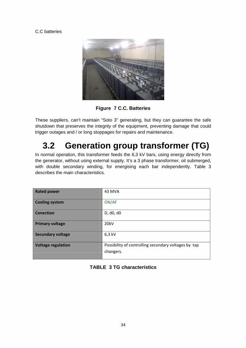
C.C batteries
Figure 7 C.C. Batteries These suppliers, can’t maintain “Soto 3” generating, but they can guarantee the safe shutdown that preserves the integrity of the equipment, preventing damage that could trigger outages and / or long stoppages for repairs and maintenance.
3.2 Generation group transformer (TG) In normal operation, this transformer feeds the 6,3 kV bars, using energy directly from the generator, without using external supply. It’s a 3 phase transformer, oil submerged, with double secondary winding, for energising each bar independently. Table 3 describes the main characteristics.
Rated power 43 MVA
Cooling system ON/AF
Conection D, d0, d0
Primary voltage 20kV
Secundary voltage 6,3 kV
Voltage regulation Possibility of controlling secondary voltages by tap changers.
TABLE 3 TG characteristics
34
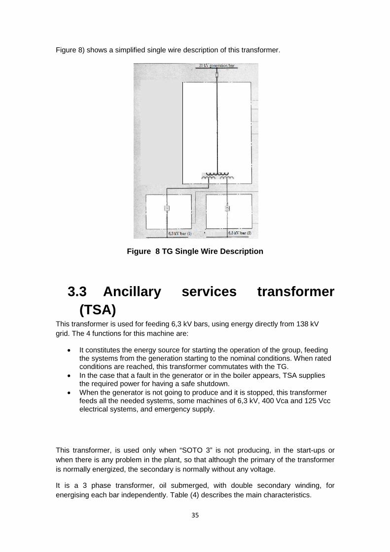
Figure 8) shows a simplified single wire description of this transformer.
Figure 8 TG Single Wire Description
3.3 Ancillary services transformer (TSA)
This transformer is used for feeding 6,3 kV bars, using energy directly from 138 kV grid. The 4 functions for this machine are:
• It constitutes the energy source for starting the operation of the group, feeding the systems from the generation starting to the nominal conditions. When rated conditions are reached, this transformer commutates with the TG.
• In the case that a fault in the generator or in the boiler appears, TSA supplies the required power for having a safe shutdown.
• When the generator is not going to produce and it is stopped, this transformer feeds all the needed systems, some machines of 6,3 kV, 400 Vca and 125 Vcc electrical systems, and emergency supply.
This transformer, is used only when “SOTO 3” is not producing, in the start-ups or when there is any problem in the plant, so that although the primary of the transformer is normally energized, the secondary is normally without any voltage.
It is a 3 phase transformer, oil submerged, with double secondary winding, for energising each bar independently. Table (4) describes the main characteristics.
35

3.3.1 Main characteristics
Rated power 43 MVA
Cooling system ON/AF
Conection D, d0, d0
Primary voltage 138kV
Secundary voltage 6,3 kV
Voltage regulation Possibility of controlling secondary voltages by tap changers.
TABLE 4: TSA Charachterics
Figure 9) shows a simplified single wire description of this transformer.
Figure 9: TSA Single Wire Description
36
3.4 Commutator between the TSA and the TG
These switches are used for making the supplying change, since feeding can’t be made simultaneously from both transformers. If that happens there will be a power transfer between the 20 kV bar and the 138 kV, damaging the whole system.
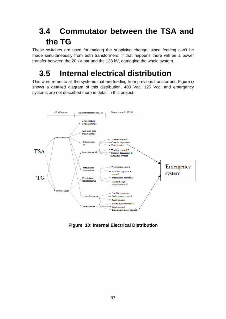
3.5 Internal electrical distribution This word refers to all the systems that are feeding from previous transformer. Figure () shows a detailed diagram of this distribution. 400 Vac, 125 Vcc, and emergency systems are not described more in detail in this project.
Figure 10: Internal Electrical Distribution
37
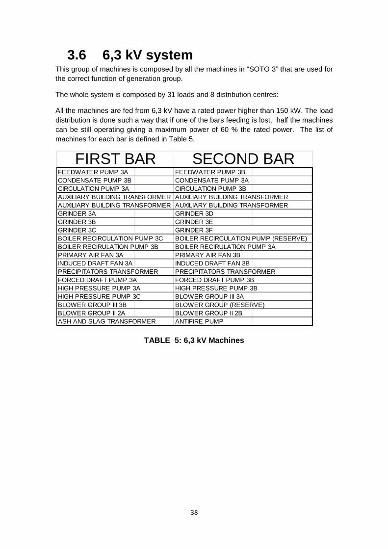
3.6 6,3 kV system This group of machines is composed by all the machines in “SOTO 3” that are used for the correct function of generation group.
The whole system is composed by 31 loads and 8 distribution centres:
All the machines are fed from 6,3 kV have a rated power higher than 150 kW. The load distribution is done such a way that if one of the bars feeding is lost, half the machines can be still operating giving a maximum power of 60 % the rated power. The list of machines for each bar is defined in Table 5.
TABLE 5: 6,3 kV Machines
FEEDWATER PUMP 3A FEEDWATER PUMP 3BCONDENSATE PUMP 3B CONDENSATE PUMP 3ACIRCULATION PUMP 3A CIRCULATION PUMP 3BAUXILIARY BUILDING TRANSFORMER AUXILIARY BUILDING TRANSFORMERAUXILIARY BUILDING TRANSFORMER AUXILIARY BUILDING TRANSFORMERGRINDER 3A GRINDER 3DGRINDER 3B GRINDER 3EGRINDER 3CBOILER RECIRCULATION PUMP 3C BOILER RECIRCULATION PUMP (RESERVE)BOILER RECIRULATION PUMP 3B BOILER RECIRULATION PUMP 3APRIMARY AIR FAN 3A PRIMARY AIR FAN 3BINDUCED DRAFT FAN 3A INDUCED DRAFT FAN 3BPRECIPITATORS TRANSFORMER PRECIPITATORS TRANSFORMERFORCED DRAFT PUMP 3A FORCED DRAFT PUMP 3BHIGH PRESSURE PUMP 3A HIGH PRESSURE PUMP 3BHIGH PRESSURE PUMP 3C BLOWER GROUP III 3ABLOWER GROUP III 3B BLOWER GROUP (RESERVE)BLOWER GROUP II 2A BLOWER GROUP II 2BASH AND SLAG TRANSFORMER ANTIFIRE PUMP
FIRST BAR SECOND BAR
GRINDER 3F
38
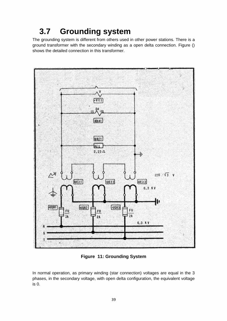
3.7 Grounding system The grounding system is different from others used in other power stations. There is a ground transformer with the secondary winding as a open delta connection. Figure () shows the detailed connection in this transformer.
Figure 11: Grounding System
In normal operation, as primary winding (star connection) voltages are equal in the 3 phases, in the secondary voltage, with open delta configuration, the equivalent voltage is 0.
39
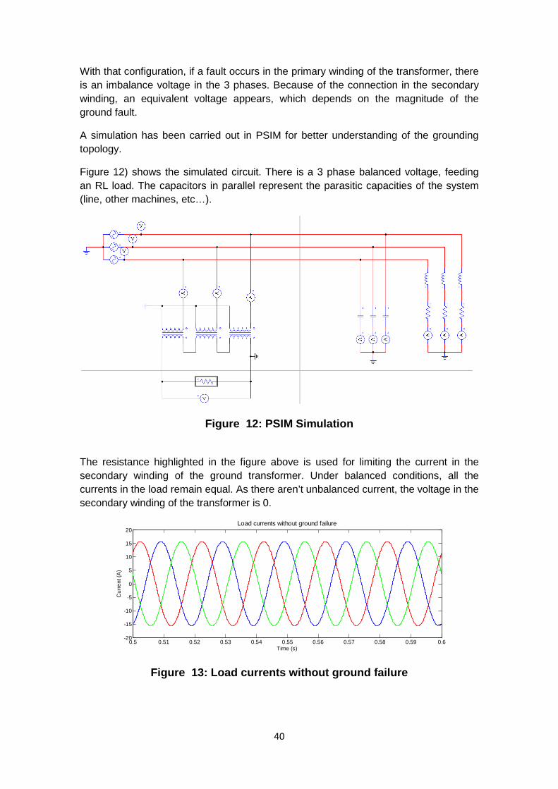
With that configuration, if a fault occurs in the primary winding of the transformer, there is an imbalance voltage in the 3 phases. Because of the connection in the secondary winding, an equivalent voltage appears, which depends on the magnitude of the ground fault.
A simulation has been carried out in PSIM for better understanding of the grounding topology.
Figure 12) shows the simulated circuit. There is a 3 phase balanced voltage, feeding an RL load. The capacitors in parallel represent the parasitic capacities of the system (line, other machines, etc…).
Figure 12: PSIM Simulation
The resistance highlighted in the figure above is used for limiting the current in the secondary winding of the ground transformer. Under balanced conditions, all the currents in the load remain equal. As there aren’t unbalanced current, the voltage in the secondary winding of the transformer is 0.
Figure 13: Load currents without ground failure
0.5 0.51 0.52 0.53 0.54 0.55 0.56 0.57 0.58 0.59 0.6-20
-15
-10
-5
0
5
10
15
20Load currents without ground failure
Time (s)
Cur
rent
(A)
40
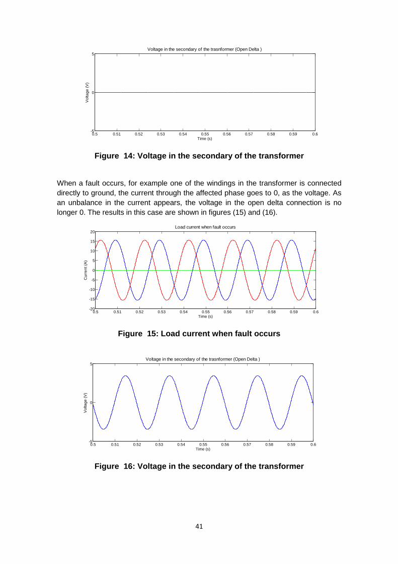
Figure 14: Voltage in the secondary of the transformer
When a fault occurs, for example one of the windings in the transformer is connected directly to ground, the current through the affected phase goes to 0, as the voltage. As an unbalance in the current appears, the voltage in the open delta connection is no longer 0. The results in this case are shown in figures (15) and (16).
Figure 15: Load current when fault occurs
Figure 16: Voltage in the secondary of the transformer
0.5 0.51 0.52 0.53 0.54 0.55 0.56 0.57 0.58 0.59 0.6-5
0
5Voltage in the secondary of the trasnformer (Open Delta )
Time (s)
Vol
tage
(V)
0.5 0.51 0.52 0.53 0.54 0.55 0.56 0.57 0.58 0.59 0.6-20
-15
-10
-5
0
5
10
15
20
Time (s)
Cur
rent
(A)
Load current when fault occurs
0.5 0.51 0.52 0.53 0.54 0.55 0.56 0.57 0.58 0.59 0.6-5
0
5
Time (s)
Vol
tage
(V)
Voltage in the secondary of the trasnformer (Open Delta )
41

3.8 Existing protection in the cabins
There are four existing topologies for protecting each cabin. There are:
• DT-35 • DM-62 and DM-72 • DN-62
Transformer protection cabins DT-35 The DT-35 type is used for protecting transformers, as the ash and slag transformer, or the precipitator’s transformer. All these machines are protected with an overcurrent relay (50/51 protection ANSI code). This relay can be either IAC51 or IAC66, both devices made by General Electric. When this relay detects a current higher than the threshold value for the protection, it sends two trip signals, one for the master relay (86 protection in the ANSI code), and the other to a switch (52 ) which is in the 6,3 kV line.
Motor protection cabin DM-62 and DM-72. Pumps, blowers and grinders, with power ratings below 900kW are included in this topology. These low power machines are protected against overcurrent. The device used in this case is an IAC66K, from General Electric. This relay, when detects a current higher than the threshold value for the protection, sends two trip signals, one for the master relay (86), and the other goes to an switch (52 in ANSI code) which is in the 6,3 kV line . In these cabins, apart from these 2 tripping signals, sends an alarm signals for the control room.
High power motor protection, DN-62 All the motors with a power rating higher than 900 kW, for example the feed water pump or the induced draft fan, are included in this topology.
Apart from having an IAC66K for overcurrent protection, these motors have a differential protection, using a PJC12K relay. Both relays make the same signals, 2 tripping signals for an 86 and a 52, as well as the alarm signal for the control room.
42
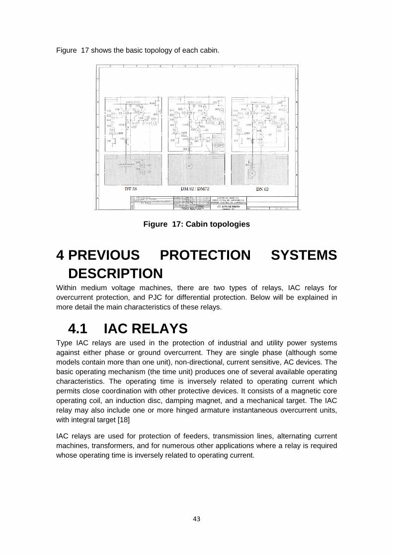
Figure 17 shows the basic topology of each cabin.
Figure 17: Cabin topologies
4 PREVIOUS PROTECTION SYSTEMS DESCRIPTION
Within medium voltage machines, there are two types of relays, IAC relays for overcurrent protection, and PJC for differential protection. Below will be explained in more detail the main characteristics of these relays.
4.1 IAC RELAYS Type IAC relays are used in the protection of industrial and utility power systems against either phase or ground overcurrent. They are single phase (although some models contain more than one unit), non-directional, current sensitive, AC devices. The basic operating mechanism (the time unit) produces one of several available operating characteristics. The operating time is inversely related to operating current which permits close coordination with other protective devices. It consists of a magnetic core operating coil, an induction disc, damping magnet, and a mechanical target. The IAC relay may also include one or more hinged armature instantaneous overcurrent units, with integral target [18]
IAC relays are used for protection of feeders, transmission lines, alternating current machines, transformers, and for numerous other applications where a relay is required whose operating time is inversely related to operating current.
43
4.1.1 Time dependent operating curve There are 6 operating characteristics available.
• Inverse time • Very inverse time • Extremely inverse time • Inverse short time • Inverse medium time • Inverse long time
4.1.2 Motor protection The IAC66K is used for motor protection. It is based on Inverse long time characteristic. These types of relays are designed for applications requiring long time delay. They allow the major area of usefulness. This Inverse long time curve is normally used in motor applications. Figure () o Annex… represents the possible working curves of inverse long time configuration[18].
Time-overcurrent units are available in several ranges to meet current pickup settings. Sensitivity is determined by discrete tap-plug settings, and a time dial provides a continuously adjustable time delay over the entire range.
4.1.3 Transformers protection The IAC51 is used for transformers protection. The curve used is Inverse time characteristic, wich is generally applied when the short-circuit current magnitude is dependent largely upon the system generating capacity at the time of the fault. Figure () o Annex…represents the posible working curves of inverse time configuration.
Time-overcurrent units are available in several ranges to meet current pickup settings. Sensitivity is determined by discrete tap-plug settings, and a time dial provides a continuously adjustable time delay over the entire range[18].
4.1.4 Instantaneous Unit Instantaneous units are used to provide tripping with no intentional time delay for currents exceeding a predetermined
value. Typically, if the fault current magnitude under maximum generating conditions triples as a fault is moved toward the relay location from the far end of the line, then an instantaneous unit is desirable.
This instantaneous unit is used for doing the instantaneus overcurrent protection (50).[LISTADO ANSI].
4.2 PJC RELAYS The PJC is a plunger relay that operates on the principle of electromagnetic attraction. The contacts are opened or closed by an armature which is attracted vertically into a small solenoid.
44

Generally, the PJC is a single element relay, but these units can be mounted in the draw out case to provide a 2 or 3-unit relay. This grouping of units in a draw out case saves valuable panel space and provides for easy testing and checking[19].
4.2.1 Relay Characteristics High-speed Operation: The contact closing time is approximately 1 cycle at twice the pickup setting.
Self-or Hand-reset: These relays have self-resetting contacts and hand-reset targets.
Calibration: The standard relays are calibrated at 60 Hz. For 25 or 50 Hz and DC applications, this calibration is correct within approximately 10 percent.
Mounting: They are surface mounted and have studs for back connection.
The use of the sensitivity current relays (PJC) for sensing differential currents, it is not the normal way of protecting. For all the motors included in the project, with differential protection, the mounting scheme is the detailed in figure(18):
Figure 18: Differential protections
In this concrete installation, the current transformers, are sensing the difference between the input and the output of the winding. In normal conditions it must be 0, but it will be different if there is any leakage.
This measurement directly reflects the differential current. This current is the one that should be calculated in a differential relay, but in this case it is not calculated, it is directly measured. With this particular situation, it is needed an overcurrent relay, for making this protection. Although the protection method is quite different from the usual, it effectively protects against differential currents. The main drawback of this protection is that the overcurrent relay has to be adjusted to the minimum, to detect the fail. In PJC relays, the minimum tripping current is 0.5 A[19].
45
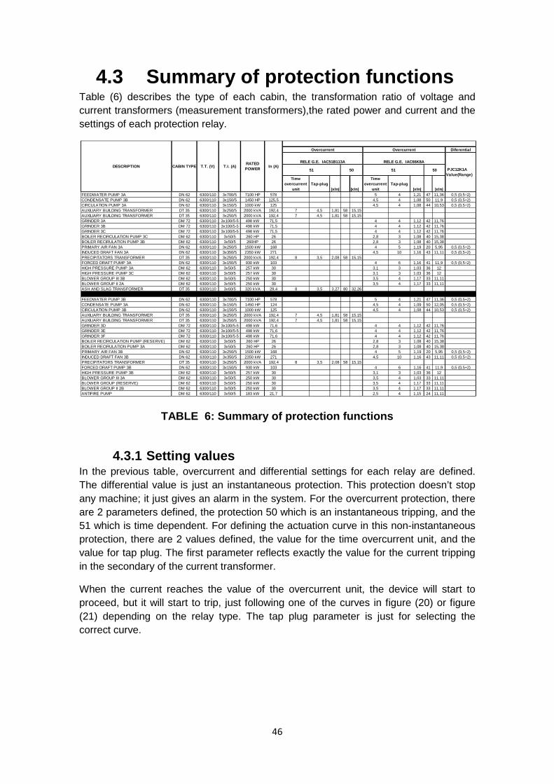
4.3 Summary of protection functions Table (6) describes the type of each cabin, the transformation ratio of voltage and current transformers (measurement transformers),the rated power and current and the settings of each protection relay.
TABLE 6: Summary of protection functions
4.3.1 Setting values In the previous table, overcurrent and differential settings for each relay are defined. The differential value is just an instantaneous protection. This protection doesn’t stop any machine; it just gives an alarm in the system. For the overcurrent protection, there are 2 parameters defined, the protection 50 which is an instantaneous tripping, and the 51 which is time dependent. For defining the actuation curve in this non-instantaneous protection, there are 2 values defined, the value for the time overcurrent unit, and the value for tap plug. The first parameter reflects exactly the value for the current tripping in the secondary of the current transformer.
When the current reaches the value of the overcurrent unit, the device will start to proceed, but it will start to trip, just following one of the curves in figure (20) or figure (21) depending on the relay type. The tap plug parameter is just for selecting the correct curve.
Diferential
Time overcurrent
unitTap-plug
|xIn| |xIn|
Time overcurrent
unitTap-plug
|xIn| |xIn|FEEDWATER PUMP 3A DN 62 6300/110 3x700/5 7100 HP 578 5 4 1,21 47 11,36 0,5 (0,5÷2)CONDENSATE PUMP 3B DN 62 6300/110 3x150/5 1450 HP 125,5 4,5 4 1,08 50 11,9 0,5 (0,5÷2)CIRCULATION PUMP 3A DN 62 6300/110 3x150/5 1000 kW 125 4,5 4 1,08 44 10,53 0,5 (0,5÷2)AUXILIARY BUILDING TRANSFORMER DT 35 6300/110 3x250/5 2000 kVA 192,4 7 4,5 1,81 58 15,15AUXILIARY BUILDING TRANSFORMER DT 35 6300/110 3x250/5 2000 kVA 192,4 7 4,5 1,81 58 15,15GRINDER 3A DM 72 6300/110 3x100/5-5 498 kW 71,5 4 4 1,12 42 11,76GRINDER 3B DM 72 6300/110 3x100/5-5 498 kW 71,5 4 4 1,12 42 11,76GRINDER 3C DM 72 6300/110 3x100/5-5 498 kW 71,5 4 4 1,12 42 11,76BOILER RECIRCULATION PUMP 3C DM 62 6300/110 3x50/5 260 HP 26 2,8 3 1,08 40 15,38BOILER RECIRULATION PUMP 3B DM 62 6300/110 3x50/5 260HP 26 2,8 3 1,08 40 15,38PRIMARY AIR FAN 3A DN 62 6300/110 3x250/5 1500 kW 168 4 5 1,19 20 5,95 0,5 (0,5÷2)INDUCED DRAFT FAN 3A DN 62 6300/110 3x350/5 2350 kW 271 4,5 10 1,16 43 11,11 0,5 (0,5÷2)PRECIPITATORS TRANSFORMER DT 35 6300/110 3x250/5 2000 kVA 192,4 8 3,5 2,08 58 15,15FORCED DRAFT PUMP 3A DN 62 6300/110 3x150/5 930 kW 103 4 6 1,16 41 11,9 0,5 (0,5÷2)HIGH PRESSURE PUMP 3A DM 62 6300/110 3x50/5 257 kW 30 3,1 3 1,03 36 12HIGH PRESSURE PUMP 3C DM 62 6300/110 3x50/5 257 kW 30 3,1 3 1,03 36 12BLOWER GROUP III 3B DM 62 6300/110 3x50/5 250 kW 30 3,5 4 1,17 33 11,11BLOWER GROUP II 2A DM 62 6300/110 3x50/5 250 kW 30 3,5 4 1,17 33 11,11ASH AND SLAG TRANSFORMER DT 35 6300/110 3x60/5 320 kVA 29,4 8 3,5 3,27 80 32,26
FEEDWATER PUMP 3B DN 62 6300/110 3x700/5 7100 HP 578 5 4 1,21 47 11,36 0,5 (0,5÷2)CONDENSATE PUMP 3A DN 62 6300/110 3x150/5 1450 HP 124 4,5 4 1,09 50 12,05 0,5 (0,5÷2)CIRCULATION PUMP 3B DN 62 6300/110 3x150/5 1000 kW 125 4,5 4 1,08 44 10,53 0,5 (0,5÷2)AUXILIARY BUILDING TRANSFORMER DT 35 6300/110 3x250/5 2000 kVA 192,4 7 4,5 1,81 58 15,15AUXILIARY BUILDING TRANSFORMER DT 35 6300/110 3x250/5 2000 kVA 192,4 7 4,5 1,81 58 15,15GRINDER 3D DM 72 6300/110 3x100/5-5 498 kW 71,6 4 4 1,12 42 11,76GRINDER 3E DM 72 6300/110 3x100/5-5 498 kW 71,6 4 4 1,12 42 11,76GRINDER 3F DM 72 6300/110 3x100/5-5 498 kW 71,6 4 4 1,12 42 11,76BOILER RECIRCULATION PUMP (RESERVE) DM 62 6300/110 3x50/5 260 HP 26 2,8 3 1,08 40 15,38BOILER RECIRULATION PUMP 3A DM 62 6300/110 3x50/5 260 HP 26 2,8 3 1,08 40 15,38PRIMARY AIR FAN 3B DN 62 6300/110 3x250/5 1500 kW 168 4 5 1,19 20 5,95 0,5 (0,5÷2)INDUCED DRAFT FAN 3B DN 62 6300/110 3x350/5 2350 kW 271 4,5 10 1,16 43 11,11 0,5 (0,5÷2)PRECIPITATORS TRANSFORMER DT 35 6300/110 3x250/5 2000 kVA 192,4 8 3,5 2,08 58 15,15FORCED DRAFT PUMP 3B DN 62 6300/110 3x150/5 930 kW 103 4 6 1,16 41 11,9 0,5 (0,5÷2)HIGH PRESSURE PUMP 3B DM 62 6300/110 3x50/5 257 kW 30 3,1 3 1,03 36 12BLOWER GROUP III 3A DM 62 6300/110 3x50/5 250 kW 30 3,5 4 1,03 33 11,11BLOWER GROUP (RESERVE) DM 62 6300/110 3x50/5 250 kW 30 3,5 4 1,17 33 11,11BLOWER GROUP II 2B DM 62 6300/110 3x50/5 250 kW 30 3,5 4 1,17 33 11,11ANTIFIRE PUMP DM 62 6300/110 3x50/5 183 kW 21,7 2,5 4 1,15 24 11,11
PJC12K1AValue(Range)
In (A)50
RELE G.E. IAC66K8A
50
OvercurrentOvercurrent
RELE G.E. IAC51B113A
51 51RATED POWERT.I. (A)T.T. (V)CABIN TYPEDESCRIPTION
46
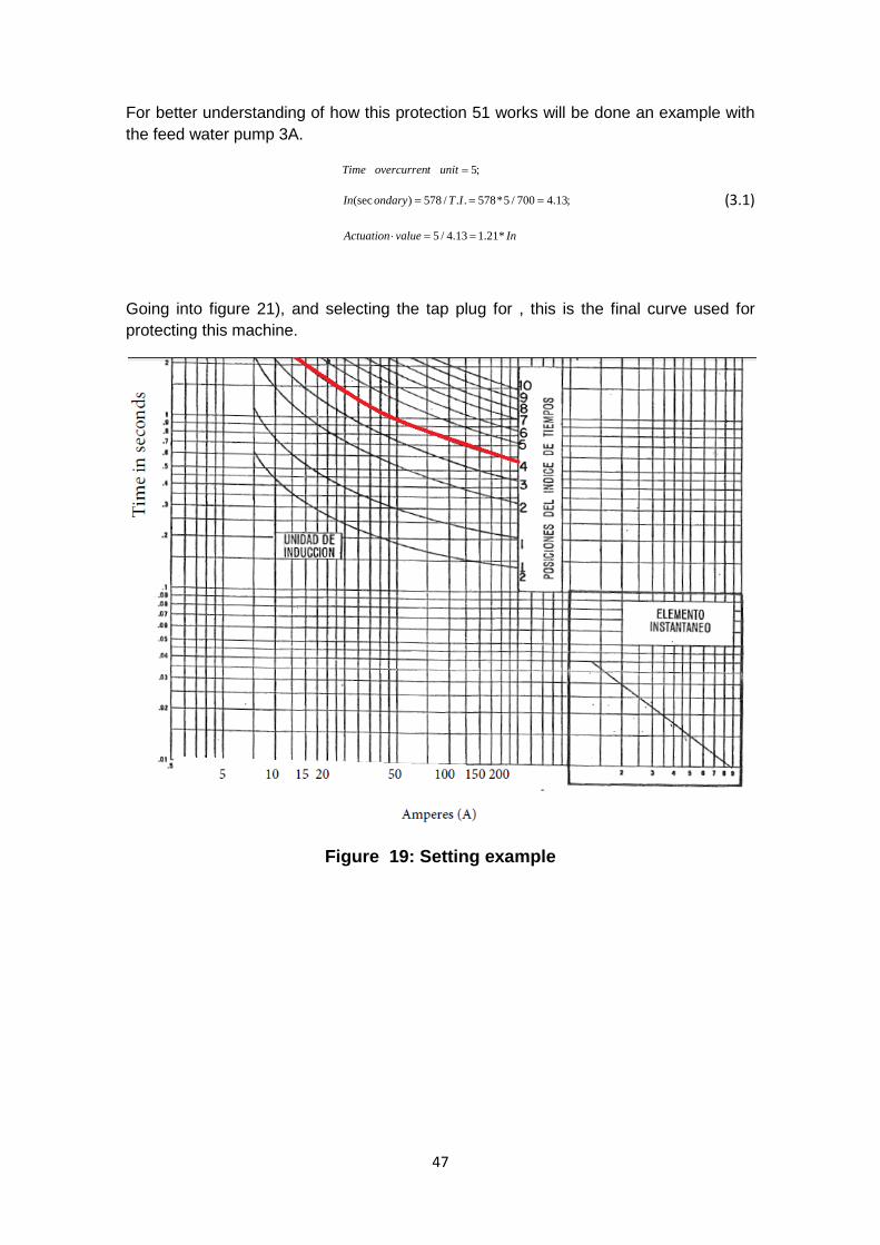
For better understanding of how this protection 51 works will be done an example with the feed water pump 3A.
InvalueActuation
ITondaryIn
unittovercurrenTime
*21.113.4/5
;13.4700/5*578../578)(sec
;5
==⋅
===
=
(3.1)
Going into figure 21), and selecting the tap plug for , this is the final curve used for protecting this machine.
Figure 19: Setting example
47
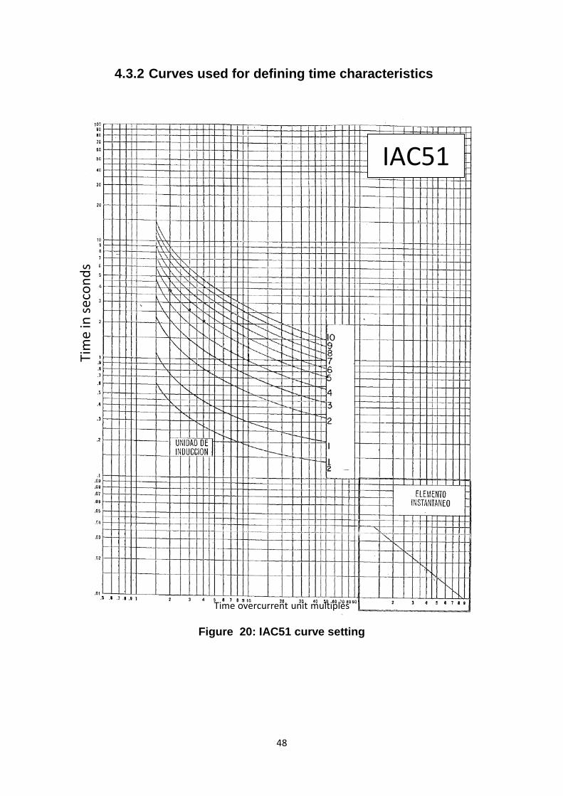
Tim
e in
sec
onds
4.3.2 Curves used for defining time characteristics
Time overcurrent unit multiples
Figure 20: IAC51 curve setting
IAC51
48
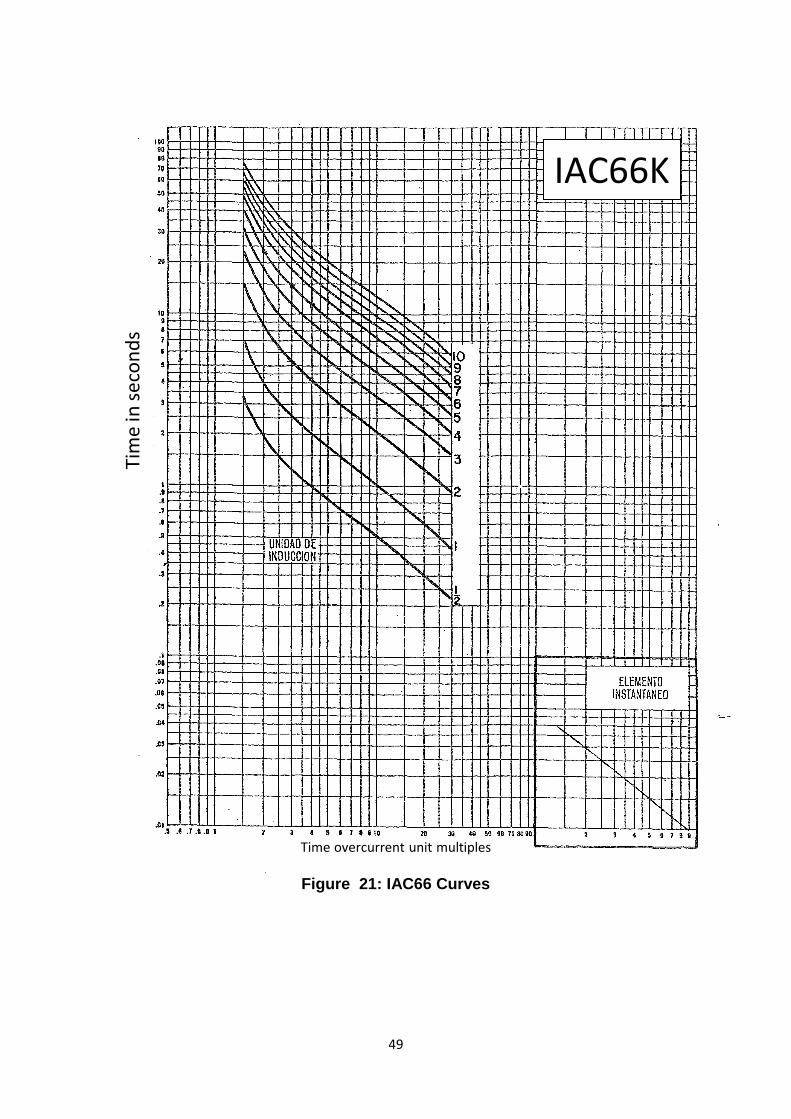
Tim
e in
sec
onds
Time overcurrent unit multiples
Figure 21: IAC66 Curves
IAC66K
49
5 Budget Request The first step in this type of projects, the first step is to make a formal request about the changes that need to be implemented. Normally when a budget request is made, there is some freedom to extend the offer, and what normally happens is that tenders meet all the requirements as well as giving more options. This extra work can be very useful sometimes, but always increases the initial total of the offer.
This Budget request is presented in different sections, of which only the most important parts will be described.
5.1 Emplacement and equipment description
A brief description about the environment, in which is shortly described everything that has to be in the Project. In the budget request is made an outline about the cabins that are included in the project. This way, the interested companies will have global knowledge about the actual system implanted in the power station, and thus better adapt the offers to the needs of the plant.
5.2 Scope of the Project Here are defined all the needed conditions for a budget to be accepted. The Main terms of the project are the following:
• Providing new relays for substituting the previous systems. • Performing the necessary engineering for installing the system. • Programming for new measure and protection functions, to replace and improve
on previous protection functions (50,51,87) • Testing the relays in the factory. These tests must include:
o Testing for all protection functions o Making the test protocols.
• Removing previous relays. • Mounting the new relays. • Testing the relays in the power plant for assuring the correct operation.
50
Apart from these main terms there are other less important conditions that must be met:
5.2.1 Documentation: Modification of previous schemes (single wire and developed schemes), must be attached in PDF. These new drawings, can be made by editing the existing drawings or by making completely new drawings.
All the documentation for new relays must be attached.
5.2.2 General conditions: • Alarms and outages must be replaced by the new electrical protections • The previous functions of the power and current converters must be assumed
by the new relays • It is necessary to indicate if the new devices have analog outputs to measure
power and current. If not, the availability of analog modules must be indicated. • It must be specified if the new relays can show the saturation level in the
measure transformers.
5.2.3 Communication and engineering: • The communication protocols allowed must be specified, including the
compulsory IEC 61850 protocol. • The relays must have a communication port for maintenance, for
communicating with a PC. • Stable communication with the Data Collection System ( DCS ) of the plant. • Communication must be time synchronized.
5.2.4 Mounting • Each relay should be mounted in the same place as the previous relay. • The previous wiring installation must be used. • The offer must include communication with the DCS
5.2.5 Factory Acceptance Test (FAT) tests • This FAT must have a minimum period of 1 day, and supervised by HC staff.
5.2.6 Spare parts • The unitary cost of recommended spare parts should be included
5.2.7 Training Course
• The offer must include a training course to show workers how to operate the new relays effectively.
51

5.3 Conditions of the project These paragraphs describe who is responsible for the following issues:
If the project provider needs administration, warehouse space or maintenance, the extra cost must be paid by them.
CTSR will provide the electricity, the pressured air, and the water required for the project. This point covers the next equipment:
Sockets:
• 63 A, 380 V, three-phase with neutral and ground. • 32 A, 380 V, three-phase with neutral and ground. • 16 A, 220 V, single-phase. • Not provided lighting (24 V). If needed, the provider must bring a shielded
220/24V safety transformer, as well as appropriate lamps.
5.4 Annexes Apart from the information included in the offer, much more information is given in the annexes. In this case there are 5 annexes, describing the cabs belonging to the project, their relative situation, electrical parameter information electrical connections, overcurrent and differential protection settings… This part is the most important in the budget request.
52
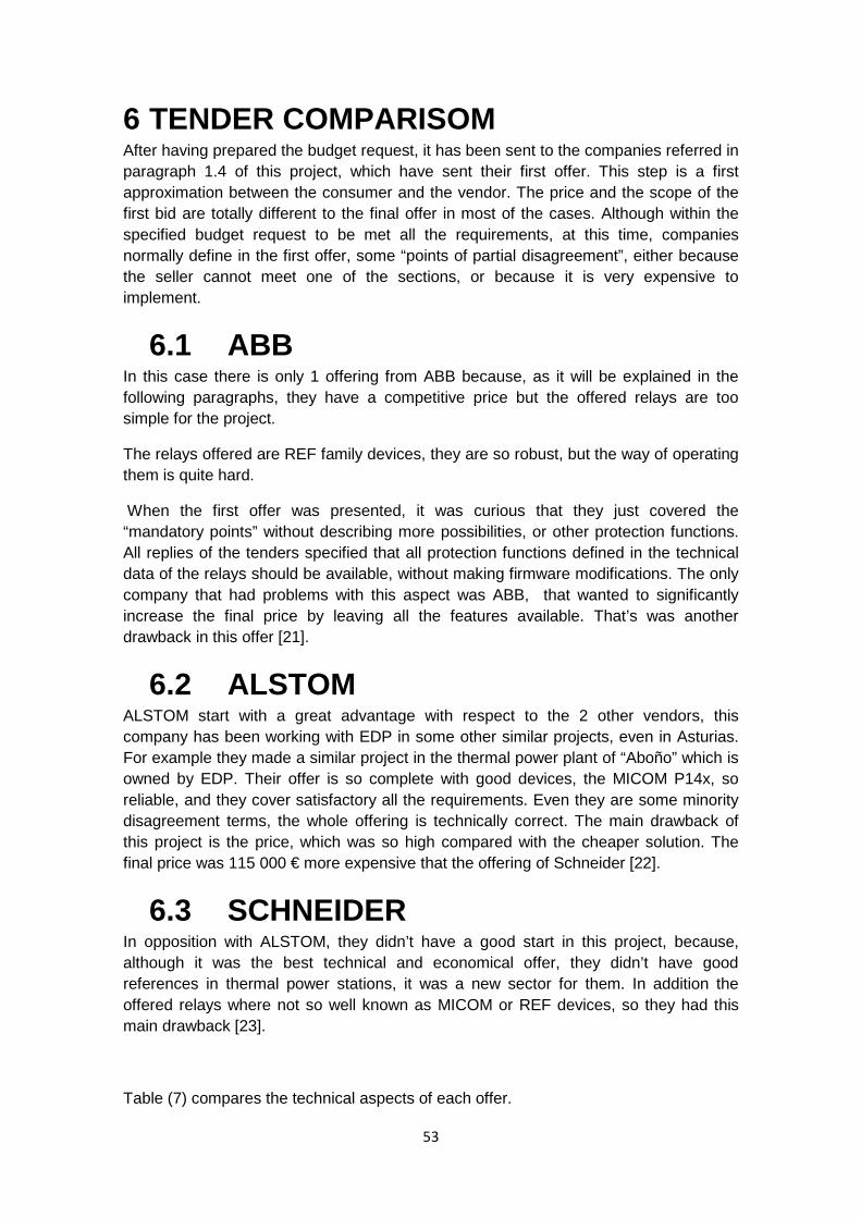
6 TENDER COMPARISOM After having prepared the budget request, it has been sent to the companies referred in paragraph 1.4 of this project, which have sent their first offer. This step is a first approximation between the consumer and the vendor. The price and the scope of the first bid are totally different to the final offer in most of the cases. Although within the specified budget request to be met all the requirements, at this time, companies normally define in the first offer, some “points of partial disagreement”, either because the seller cannot meet one of the sections, or because it is very expensive to implement.
6.1 ABB In this case there is only 1 offering from ABB because, as it will be explained in the following paragraphs, they have a competitive price but the offered relays are too simple for the project.
The relays offered are REF family devices, they are so robust, but the way of operating them is quite hard.
When the first offer was presented, it was curious that they just covered the “mandatory points” without describing more possibilities, or other protection functions. All replies of the tenders specified that all protection functions defined in the technical data of the relays should be available, without making firmware modifications. The only company that had problems with this aspect was ABB, that wanted to significantly increase the final price by leaving all the features available. That’s was another drawback in this offer [21].
6.2 ALSTOM ALSTOM start with a great advantage with respect to the 2 other vendors, this company has been working with EDP in some other similar projects, even in Asturias. For example they made a similar project in the thermal power plant of “Aboño” which is owned by EDP. Their offer is so complete with good devices, the MICOM P14x, so reliable, and they cover satisfactory all the requirements. Even they are some minority disagreement terms, the whole offering is technically correct. The main drawback of this project is the price, which was so high compared with the cheaper solution. The final price was 115 000 € more expensive that the offering of Schneider [22].
6.3 SCHNEIDER In opposition with ALSTOM, they didn’t have a good start in this project, because, although it was the best technical and economical offer, they didn’t have good references in thermal power stations, it was a new sector for them. In addition the offered relays where not so well known as MICOM or REF devices, so they had this main drawback [23].
Table (7) compares the technical aspects of each offer.
53
TABLE 7: Tender Comparison
ABB ALSTOM SCHNEIDERRelay definition REF 615 F, B, A / REM 620 MICOM Agile P14N / P14D VAMP 52 / VAMP 230
Offered protection function 50, 51, 87M50, 50N, 51, 50/51N, 68, 46, 46BC, 37, 49, 50BF, 64N, 87, 51LR, 67, 27, 59,
47, 81, VTS, CTS.
50, 51, 50N/51N, 67, 59, 49, 59, 27, 47, 68, 46, 47, 48, 37, 86,
66, 50BF, 81,LR.New protection functions Avaiable AvaiableMinimum value for differential protection Minimum = 0,05 A Minimum = 0,1 A
Voltage measureYes Yes
VAMP 230 = yes / VAMP 52 = No
Visualización medidasVoltage, Current, Power, Power factor Voltage, Current, Power factor
Voltage, Current, Power, Power factor
Event register Yes Yes Yes
Comunication system Ethernet RJ45 USB for conection with PC. Ethernet conection
Ethernet conection
Comunication protocol IEC 61850 IEC 61850 IEC 61850Redundancy 2 redundant comunications 2 redundant comunication 2 redundant comunicationSoftware PCM6000 +Ethernet wire RJ45 Free (MICOM S1 Studio-Agile) Included
Programing includedNew protection functions needs a firmware modification) Remplacement of previous functions
Remplacement of previous functions
Analog inputs outputs Yes No YesRequired voltage 110 - 250 Vcc 125 VDCsynchronization with DCS (Distributed Control System)
Yes Yes Yes
Pruebas FAT (factory aceptance test) 2 days 1 day 2 daysPruebas in CTSR (Thermal plant of Soto de Ribera) 5 days 3 days 3 days
Adequation of schemes Yes, by editing the old PDF Yes, by editing the old PDF Yes, by Autocad design
Old protection disassembly Yes Yes YesNew protections mounting Yes Yes in an aluminium plate Yes in an aluminium plateDelivery time 5 months 5 months 3 monthsWork time 21 days of work 15 days Depending on CTSR productionCTSR staff training 2 days 1 journey 3 daysRepuestos Optional Included
References of previous similar projectsNo Yes
Lot of references, but anye Spanish ref.
PROTECTION AND MEASURE EQUIPMENT 6.3 Kv
54

6.3.1 Technical comparison
Apart from the overcurrent (50,51) and differential protection (87) , there are other options to implement in the new relays. The defined protection functions that appear in the table are:
• Protection 27: Undervoltage protection. A protection that operates when its input voltage is less than a predetermined value.
• Protection 37: Undercurrent or under power relay. A protection that functions when the current or power flow decreases below a predetermined value.
• Protection 46 : Reverse-phase or phase-balance current protection. A protection that functions when the polyphase currents are of reverse-phase sequence or when the polyphase currents are unbalanced or contain negative phase-sequence components above a given amount.
• Protection 47 : phase-sequence or phase-balance voltage protection. A protection that functions upon a predetermined value of polyphase voltage in the desired phase sequence, when the polyphase voltages are unbalanced, or when the negative phase-sequence voltage exceeds a given amount.
• Protection 48 : Incomplete sequence protection. A protection that generally returns the equipment to the normal, or off, position and locks it out if the normal starting, operating, or stopping sequence is not properly completed within a predetermined time.
• Protection 49 : Thermal imaging. A protection that functions when the temperature of a machine armature winding or other load-carrying winding or element ofa machine or power transformer exceeds predetermined value.
• Protection 51LR : Locked rotor protection. Functions when the starting time is so
high, or when there is something blocking the shaft (overcurrent protection).
55
• Protection 59 : overvoltage protection. Operates when its input voltage is more than a predetermined value.
• Protection 64 : Grounding protection. Operates upon failure of machine or other apparatus insulation to ground.
• Protection 66 : Controls the number of starts of a machine.
• Protection 67 : Ac directional overcurrent protection. Functions on a desired value of ac overcurrent flowing in a predetermined direction.
Apart from the new protection functions, there are other aspects (highlighted in bond) that have to be taken into account:
MINIMUM VALUE FOR DIFFERENTIAL PROTECTION This parameter is so important, because as it is explained in previous paragraphs the old relay was an overcurrent relay. The value of this previous relay was adjusted to the minimum because the differential current must be 0 in normal operation, but when there is a failure, this current can be so low. The previous set point was 0.5 A , and for the new relay it should be adjustable to a lower value. Both ALSTOM and Schneider can fulfill this requirement.
Analog inputs/outputs All the measurements with the previous relays where analog. The whole process of implementing the DCS in Soto 3, will finish in 2015, so the final implementation of totally digital signals will be done by that date. For maintaining the control system and the measurements until then, there are needed some analog communication with the new relays. Relays MICOM P14x don’t have analog communication, which is an important disadvantage, but they remedied this problem by using digital to analog converters, which are external devices for converting measurements.
Adequation of new schemes Since the new relays are implanted in the power station, the former schemes are not valid anymore, so it is needed to adapt them. The cheapest solution for the companies is normally editing the drawings just by a PDF tool. Both ALSTOM and ABB had selected this option in the offerings. The best option for CTSR could be, as Schneider offered, the
56

creation of a new collection of PDF by designing them on AutoCAD. This could be the best option, as the new schemes will be much better. The only drawback is that the new collection must be checked scheme by scheme to preserve all existing nomenclature within the plant.
References This is another aspect that must be taken into account. Having good references always keeps one company in a better position than the others. In this case Alstom has this clearly advantage.
Work time in the plant This is, by far, the most important aspect. The production of each power station depends on the energy demand, the technical conditions of each plant, the percentage of renewable energy produced, etc. All these factors affect the energy production in Soto to. The main idea is not to stop production when this work is done, doing all the work during the periods when the plant is not producing.
After comparing the most the most remarkable technical aspects, next table shows a comparison between the prices.
6.3.2 Economical comparison The final prices are described in TABLE 8
TABLE 8: Economical comparison
The major difference between Schneider offering and the other 2 is the price of the relays, which is nearly half. This fact makes high differences. ALSTOM did an offering for another project that must be done in the power station in 2014, the general revision of the whole plant. The approximately value for this project is 1M€, so they decided to reduce the total price by joining both offerings, even so the final price was not competitive.
After making all the negotiation process, the better offer was the one done by Schneider, and the final decision was to have an agreement with Schneider for doing the project.
ABB ALSTOM SCHNEIDERRelays price 190.000 180.000 103.000Engineering 40.000 25.000 19.000Mounting and testing 80.000 70.000 58.800Training for the CTSR workers 5.000 8000 6000Replacement parts 15.000 4.600 6500TOTAL 330.000 287.600 193.300
Disaggregated prices
57
7 TENDER SELECTION Schneider tender has been finally selected. After 2 previous offers the final bid was made the 25th April of 2013, and accepted three weeks after. Once it is the supplier selected, both companies has to give more information from each part, for example, EDP must give more information about some parameters in the plant, as the short-circuit power. On the other side, Schneider has to start giving exact delivery times, some information about the group that will carry out this project, some detailed information about the relays software, etc… For having a control of the project there will be monthly meetings during the delivery time.
Tender conditions will be detailed in following paragraphs.
7.1 Technical conditions For the protection of all cabins in the project, VAMP relays will be used. In this last offer, Schneider included a long list of references about these relays, as were asked after receiving their first offer. There are some references from companies in all over the world, even for thermal plants, but there isn’t any offer for any Spanish thermal plant, as CTSR will be the first power station using these types of relays.
As it is mentioned in section 2, there are 4 types of cabins. DT 35, DM 62 and DM72; will be protected against overcurrent using VAMP 230, and for DN62 cabs, will be used VAMP 230 for overcurrent protection and VAMP 52 for differential protection. In addition to the existing protections functions, new functions will be proposed to implement, as an alarm mode.
Typical applications for VAMP52 and VAMP230 are low and medium voltage industrial processes, power plants, marine and offshore installations normally as motor protections. Compared with other devices used for the same application, highlights the simplified way of using them, with a very friendly interface, which is so important in some cases. Another advantage of VAMP relays, with respect to the previous devices is the ability to measure currents, voltages, active, reactive and apparent power as well as energy measurements. In the datasheet [Datasheet de los VAMP] they are all the protection functions available to setting on these devices as well as the connection diagrams, the dimensional drawings and some other important information. Some of the parameters included in this documentation are shown in TABLE 9
58
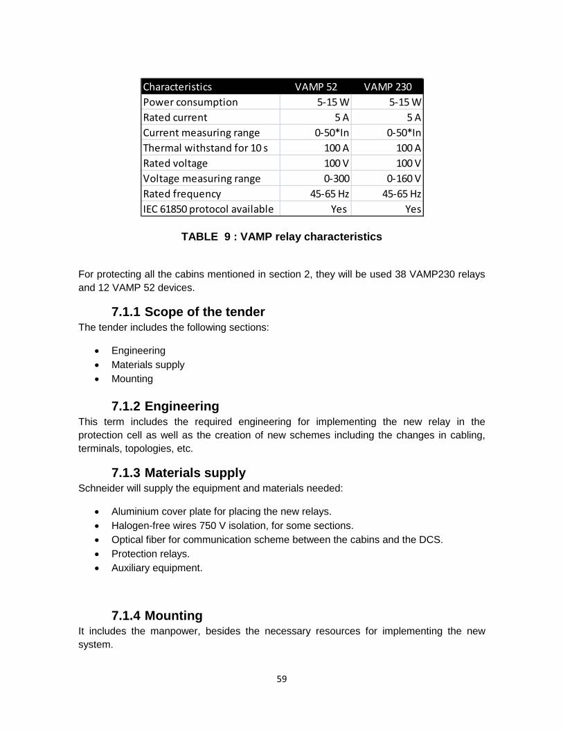
TABLE 9 : VAMP relay characteristics
For protecting all the cabins mentioned in section 2, they will be used 38 VAMP230 relays and 12 VAMP 52 devices.
7.1.1 Scope of the tender The tender includes the following sections:
• Engineering • Materials supply • Mounting
7.1.2 Engineering This term includes the required engineering for implementing the new relay in the protection cell as well as the creation of new schemes including the changes in cabling, terminals, topologies, etc.
7.1.3 Materials supply Schneider will supply the equipment and materials needed:
• Aluminium cover plate for placing the new relays. • Halogen-free wires 750 V isolation, for some sections. • Optical fiber for communication scheme between the cabins and the DCS. • Protection relays. • Auxiliary equipment.
7.1.4 Mounting It includes the manpower, besides the necessary resources for implementing the new system.
Characteristics VAMP 52 VAMP 230Power consumption 5-15 W 5-15 WRated current 5 A 5 ACurrent measuring range 0-50*In 0-50*InThermal withstand for 10 s 100 A 100 ARated voltage 100 V 100 VVoltage measuring range 0-300 0-160 VRated frequency 45-65 Hz 45-65 HzIEC 61850 protocol available Yes Yes
59

7.1.5 General description for the offer The basic steps required in each cabin are:
• Disassemble of previous relays as well as mounting the new ones, making the cabling changes required.
• Create a new scheme for the implementation of the new relay, delivering paper and electronic copies.
• Set the old protection function as tripping signals, and the new functions as alarms.
The commissioning includes:
• Internal wiring test • Upload protection settings • Check the protection relays • Check the protocol compability.
7.2 Economical conditions
In this tender are defined some agreement points defined in the meetings, previous to the final offer.
• All the protection functions are available. • The minimum value for the differential protection is 0,1 A. • Measurements viewing in the local display of the relay. • Local alarms in the relay. • The software for controlling the relays is included. • Feeding voltage 125 Vcc. • Included FAT tests. • Delivery time: 12 weeks.
Table 10 includes both disaggregated prices as the final price of the project.
60
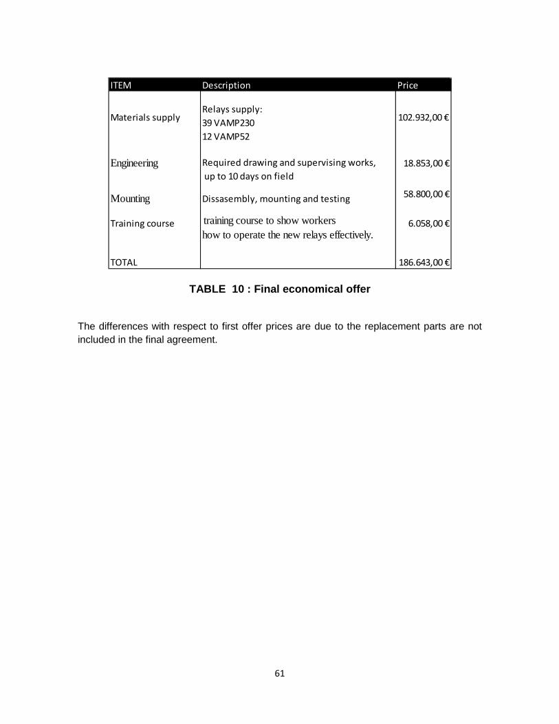
TABLE 10 : Final economical offer
The differences with respect to first offer prices are due to the replacement parts are not included in the final agreement.
ITEM Description Price
Materials supplyRelays supply:39 VAMP23012 VAMP52
102.932,00 €
Engineering Required drawing and supervising works, up to 10 days on field
18.853,00 €
Mounting Dissasembly, mounting and testing 58.800,00 €
Training course training course to show workers how to operate the new relays effectively.
6.058,00 €
TOTAL 186.643,00 €
61

8 NEW PROTECTION FUNCTIONS Once the project is awarded to the company Schneider Electric, the next step is to define the new protection functions for this motors included. This new relays the VAMP series, as it is mentiones in the technical data [Referencia o anexo de los reles de protección], they cover a wide range of functions, considering for the project the following:
• Thermal imaging (49) • Reverse-phase (46) • excessive starting time (48)1 • Locked rotor (51LR)1 • Undervoltage (27) • Anti back-spin protection (27Abs) • Too frequent start-ups (66)1 • Undercurrent (37)
1Only for motors.
This new functions will implemented only as an alarm, being so important that they can’t stop operation, just because one of the new function is bad adjusted, for example. With all this new technology it must be conservative, because an untimely stop can cause many loses.
From now, they will be explained the new protection functions, covering both the principle of operation and the setting values.
8.1 Thermal imaging (49) The majority of winding failures are either indirectly or directly caused by overloading, that causes always an increment in the temperature of the machine. The generally accepted
rule is that insulation life is halved for each 10° C rise in temperature above the rated value, modified by the length of time spent at the higher temperature. As an electrical machine has a relatively large heat storage capacity, it follows that infrequent overloads of short duration may not adversely affect the machine. However, sustained overloads of only a few percent may result in premature ageing and insulation failure[24].
Furthermore, the thermal withstand capability of the motor is affected by heating in the winding prior to a fault. It is therefore important that the relay characteristic takes account of the extremes of zero and full-load pre-fault current known respectively as the ‘Cold’ and ‘Hot’ conditions[25].
The variety of motor designs, diverse applications, variety of possible abnormal operating conditions and resulting modes of failure result in a complex thermal relationship. A generic
62

mathematical model that is accurate is therefore impossible to create. However, it is possible to develop an approximate model if it is assumed that the motor is a homogeneous body, creating and dissipating heat at a rate proportional to temperature rise. This is the principle behind the ‘thermal replica’ model of a motor used for overload protection[25].
A general curve for thermal electrical relays, based on the heating effect and on the time constant, is given by the following formula:
22
22
)(ln
BIkI
IpIt⋅−
−⋅=τ
(8.1)
Table 11 specifies all the variables description and their final values
Variable Description Value
t Operating time (s) Derived from the formula
τ Time constant (s) For P>1000 ; τ = 20 min[Referencia curso vip].
For P<1000 ; τ = 10 min. [Referencia curso vip].
Ib Basic current (A) Rated current (depends on the machine)
k Thermal constant K=1.15[Referencia curso vip]
I Relay current (A) Fault current sensed by the relay
Ip Current previous to fail (A)
Specified load current before the overload occurs (normally rated current)
TABLE 11 Parameters for thermal imaging protection
With these parameters, the curves valid for all the machines in this project are represented in figure 22:
63

Figure 22 :Thermal protection curve
This figured is analysed in terms of time and multiples of rated current, so it can be used for all the machines inside this project.
8.2 Reverse phase (46) Negative phase sequence current is generated from an unbalanced current condition, such as unbalanced loading, loss of one phase or single phase faults[26].
Considering the equivalent circuits for positive and negative phase sequence currents shown in Figure(), the magnetizing impedance being neglected. [26].
Figure 23 : Direct and inverse equivalent circuits
0 5 10 15 20 25 30 35 40 45 500
20
40
60
80
100
Measured current with respect with the nominal speed(*In)
Tim
e(s)
THERMAL PROTECTION
Cold curve P<1000MWCold curve P>1000MW
64
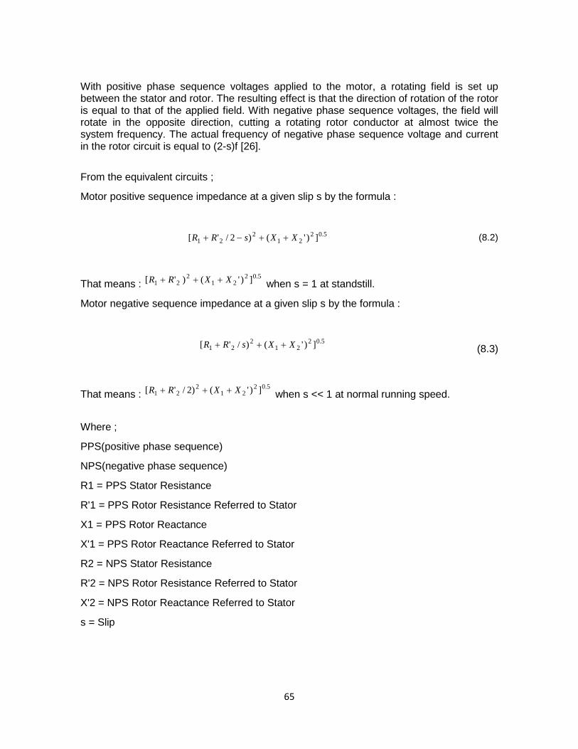
With positive phase sequence voltages applied to the motor, a rotating field is set up between the stator and rotor. The resulting effect is that the direction of rotation of the rotor is equal to that of the applied field. With negative phase sequence voltages, the field will rotate in the opposite direction, cutting a rotating rotor conductor at almost twice the system frequency. The actual frequency of negative phase sequence voltage and current in the rotor circuit is equal to (2-s)f [26]. From the equivalent circuits ;
Motor positive sequence impedance at a given slip s by the formula :
5.02
212
21 ])'()2/'[ XXsRR ++−+ (8.2)
That means : 5.02
212
21 ])'()'[ XXRR +++ when s = 1 at standstill.
Motor negative sequence impedance at a given slip s by the formula :
5.02
212
21 ])'()/'[ XXsRR +++ (8.3)
That means : 5.02
212
21 ])'()2/'[ XXRR +++ when s << 1 at normal running speed.
Where ;
PPS(positive phase sequence)
NPS(negative phase sequence)
R1 = PPS Stator Resistance
R'1 = PPS Rotor Resistance Referred to Stator
X1 = PPS Rotor Reactance
X'1 = PPS Rotor Reactance Referred to Stator
R2 = NPS Stator Resistance
R'2 = NPS Rotor Resistance Referred to Stator
X'2 = NPS Rotor Reactance Referred to Stator
s = Slip
65
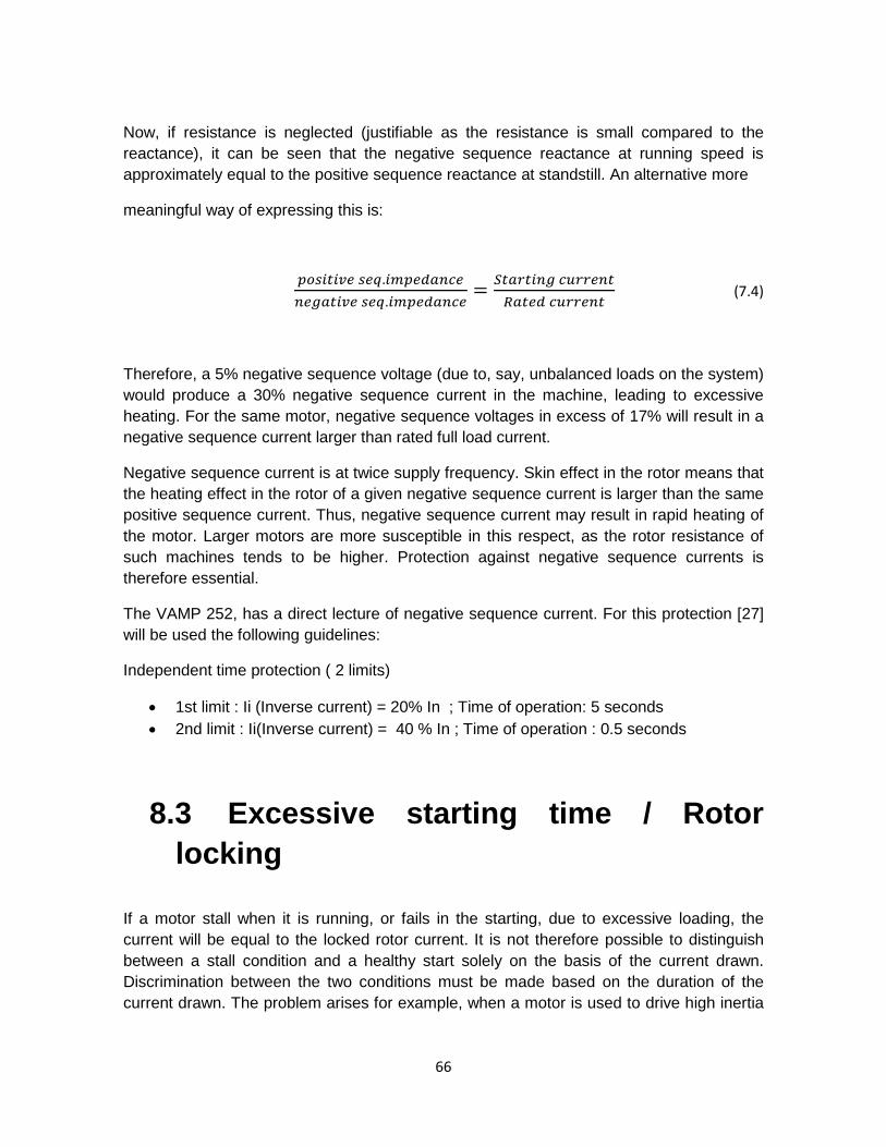
Now, if resistance is neglected (justifiable as the resistance is small compared to the reactance), it can be seen that the negative sequence reactance at running speed is approximately equal to the positive sequence reactance at standstill. An alternative more
meaningful way of expressing this is:
𝑝𝑜𝑠𝑖𝑡𝑖𝑣𝑒 𝑠𝑒𝑞.𝑖𝑚𝑝𝑒𝑑𝑎𝑛𝑐𝑒𝑛𝑒𝑔𝑎𝑡𝑖𝑣𝑒 𝑠𝑒𝑞.𝑖𝑚𝑝𝑒𝑑𝑎𝑛𝑐𝑒
= 𝑆𝑡𝑎𝑟𝑡𝑖𝑛𝑔 𝑐𝑢𝑟𝑟𝑒𝑛𝑡𝑅𝑎𝑡𝑒𝑑 𝑐𝑢𝑟𝑟𝑒𝑛𝑡
(7.4)
Therefore, a 5% negative sequence voltage (due to, say, unbalanced loads on the system) would produce a 30% negative sequence current in the machine, leading to excessive heating. For the same motor, negative sequence voltages in excess of 17% will result in a negative sequence current larger than rated full load current.
Negative sequence current is at twice supply frequency. Skin effect in the rotor means that the heating effect in the rotor of a given negative sequence current is larger than the same positive sequence current. Thus, negative sequence current may result in rapid heating of the motor. Larger motors are more susceptible in this respect, as the rotor resistance of such machines tends to be higher. Protection against negative sequence currents is therefore essential.
The VAMP 252, has a direct lecture of negative sequence current. For this protection [27] will be used the following guidelines:
Independent time protection ( 2 limits)
• 1st limit : Ii (Inverse current) = 20% In ; Time of operation: 5 seconds • 2nd limit : Ii(Inverse current) = 40 % In ; Time of operation : 0.5 seconds
8.3 Excessive starting time / Rotor locking
If a motor stall when it is running, or fails in the starting, due to excessive loading, the current will be equal to the locked rotor current. It is not therefore possible to distinguish between a stall condition and a healthy start solely on the basis of the current drawn. Discrimination between the two conditions must be made based on the duration of the current drawn. The problem arises for example, when a motor is used to drive high inertia
66
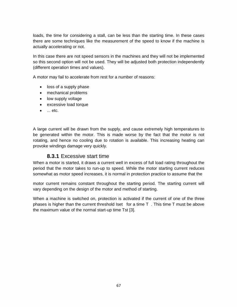
loads, the time for considering a stall, can be less than the starting time. In these cases there are some techniques like the measurement of the speed to know if the machine is actually accelerating or not.
In this case there are not speed sensors in the machines and they will not be implemented so this second option will not be used. They will be adjusted both protection independently (different operation times and values).
A motor may fail to accelerate from rest for a number of reasons:
• loss of a supply phase • mechanical problems • low supply voltage • excessive load torque • ... etc.
A large current will be drawn from the supply, and cause extremely high temperatures to be generated within the motor. This is made worse by the fact that the motor is not rotating, and hence no cooling due to rotation is available. This increasing heating can provoke windings damage very quickly.
8.3.1 Excessive start time When a motor is started, it draws a current well in excess of full load rating throughout the period that the motor takes to run-up to speed. While the motor starting current reduces somewhat as motor speed increases, it is normal in protection practice to assume that the
motor current remains constant throughout the starting period. The starting current will vary depending on the design of the motor and method of starting.
When a machine is switched on, protection is activated if the current of one of the three phases is higher than the current threshold Iset for a time T . This time T must be above the maximum value of the normal start-up time Tst [3].
67

Figure 24: Excessive start time setting
The origin of start-up can be detected in one of the following two ways:
• Using the information that the switching device is closed; • When the current rises above a low threshold (for example, 5% of In).
The settings for this protection are obtained from Schneider guidelines [26]:
• For Imachine > 1.3*In • Actuation time: T = Starting time + 3 seconds;
Taking into account that it is a new protection to implement it is better to be less restrictive. Moreover, there are some specifications in the datasheet of the medium voltage motor (in all of them) that assures the motor safety with this setting. These motors can withstand 1,5* In more than 1 minute without damaging the motor.
8.3.2 Rotor locking (51LR) This protection is locked during start-up. It will be activated when Imachine = In for 20 seconds.
In steady-state operating conditions, the protection is activated when the current of one of the three phases is higher than the current threshold Is for a time exceeding the time delay Tlr. Figure () shows an example of rotor locking [3].
68
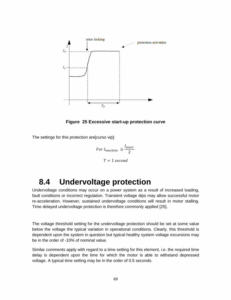
Figure 25 Excessive start-up protection curve
The settings for this protection are[curso vip]:
𝐹𝑜𝑟 𝐼𝑚𝑎𝑐ℎ𝑖𝑛𝑒 ≥𝐼𝑠𝑡𝑎𝑟𝑡
2
𝑇 = 1 𝑠𝑒𝑐𝑜𝑛𝑑
8.4 Undervoltage protection Undervoltage conditions may occur on a power system as a result of increased loading, fault conditions or incorrect regulation. Transient voltage dips may allow successful motor re-acceleration. However, sustained undervoltage conditions will result in motor stalling. Time delayed undervoltage protection is therefore commonly applied [25].
The voltage threshold setting for the undervoltage protection should be set at some value below the voltage the typical variation in operational conditions. Clearly, this threshold is dependent upon the system in question but typical healthy system voltage excursions may be in the order of -10% of nominal value.
Similar comments apply with regard to a time setting for this element, i.e. the required time delay is dependent upon the time for which the motor is able to withstand depressed voltage. A typical time setting may be in the order of 0.5 seconds.
69
The decided values for setting this protection in all machines will be defined as follows [Curso vip]:
Vthreshold=0.75*Un (rated voltage).
Time = 1 second.
8.5 ABs-Anti back-spin protection (27 Abs)
A motor may be driving a very high inertia load. Once the motor is switched off, the rotor may continue turning for a considerable time as it decelerates. The motor has now become a generator and is now applying supply voltage out of phase that may result in catastrophic failure. In some other applications for example when a motor is used for pumping, after the motor stops, the liquid may fall back down the pipe and spin the rotor backwards. It would be very undesirable to start the motor at this time. In these circumstances the anti-backspin function is used to detect when the rotor has completely stopped, in order to allow re-starting of the motor [25].
For setting this protection function, the threshold voltage must be very low for assuring that the motor is stopped already. The defined time and voltage are:
Vthreshold=0.2*Un (rated voltage). Time = 0.5 seconds.
70
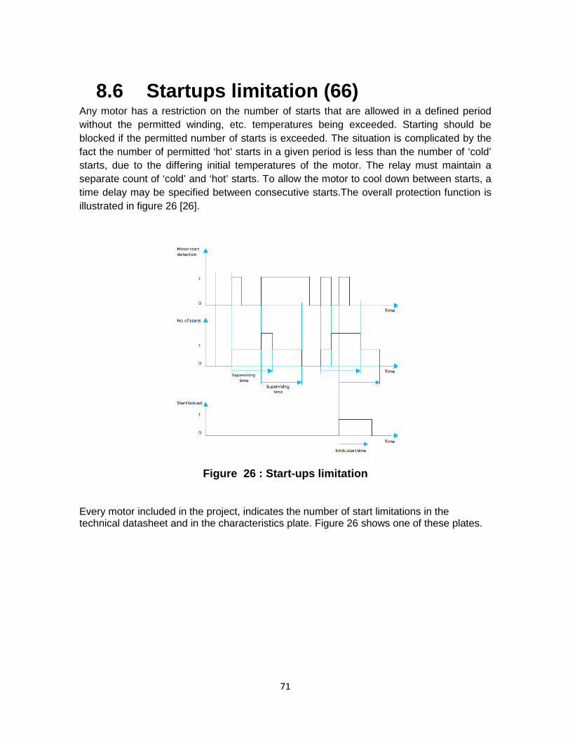
8.6 Startups limitation (66) Any motor has a restriction on the number of starts that are allowed in a defined period without the permitted winding, etc. temperatures being exceeded. Starting should be blocked if the permitted number of starts is exceeded. The situation is complicated by the fact the number of permitted ‘hot’ starts in a given period is less than the number of ‘cold’ starts, due to the differing initial temperatures of the motor. The relay must maintain a separate count of ‘cold’ and ‘hot’ starts. To allow the motor to cool down between starts, a time delay may be specified between consecutive starts.The overall protection function is illustrated in figure 26 [26].
Figure 26 : Start-ups limitation
Every motor included in the project, indicates the number of start limitations in the technical datasheet and in the characteristics plate. Figure 26 shows one of these plates.
71
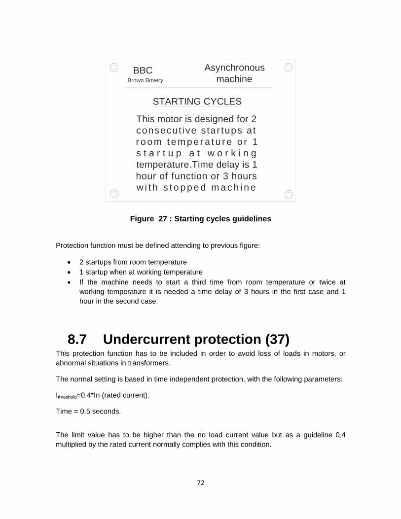
Figure 27 : Starting cycles guidelines
Protection function must be defined attending to previous figure:
• 2 startups from room temperature • 1 startup when at working temperature • If the machine needs to start a third time from room temperature or twice at
working temperature it is needed a time delay of 3 hours in the first case and 1 hour in the second case.
8.7 Undercurrent protection (37) This protection function has to be included in order to avoid loss of loads in motors, or abnormal situations in transformers.
The normal setting is based in time independent protection, with the following parameters:
Ithreshold=0.4*In (rated current).
Time = 0.5 seconds.
The limit value has to be higher than the no load current value but as a guideline 0,4 multiplied by the rated current normally complies with this condition.
BBCBrown Bovery
Asynchronousmachine
This motor is designed for 2consecut ive star tups atr oom tempe r a tu r e o r 1s t a r t u p a t w o r k i n gtemperature.Time delay is 1hour of function or 3 hoursw i t h s t o p p e d m a c h i n e
STARTING CYCLES
72

9 CONCLUSIONS The operation of a thermal plant has been explained in detailed. All the 6,3 kV machines are well defined, both main functions and the situation in the energy production process. Also the feeding system and the grounding have been properly defined, for favouring better understanding of the complex generation system.
As a result of a detailed analysis, the best supplier has been selected attending to economical and technical reasons. All the conditions are explained in detail in this project. The following conditions are mandatory for the supplier:
• Delivering relays in 12 weeks as a maximum term. • Programming them , and checking all the functions required • Assure the correct operation.
It is safe to say that this project properly defines all the issues related to the replacement of previous protections in 6,3 kV cabins.
73

10 FUTURE DEVELOPMENTS By the end of this year this project should be carried out. After the project is finished, the control and monitoring system will work as it was working before the implementation of the new relays. There is not a control system for connecting all this new information yet. The next step will be the implementation of a DCS control to perform all medium voltage machines faster and in a more reliable way. The implementation of this new system is scheduled for March 2014. This project will be conducted with the company EMERSON which will provide a Scada system called Ovation for controlling the power plant. This project started in parallel with the substitution of 6.3 kV cabins, but due to the higher complexity has a finishing date furthest in time. With respect to implemented relays, as it is mentioned in the budget request section, the analog outputs are needed to maintain all measurement systems before implementing the DCS, and also the relays must have IEC 61850 communication, to be able, from March 2014 to start using digital signals.
Apart from the DCS implementation, the relays substitution must be done also in the Generator, the group transformer and in the ancillary services transformer. Schneider will carry out this project, being scheduled for March 2014, while implementing the DCS. The relays used for this project are MICOM relays.
74
11 QUALITY REPORT It’s important to point out that for doing this master thesis, there are so many details that can’t be explained properly due to confidentiality problems. The other main drawback for concluding a good report, is that the information about some characteristics of some machines were not easy to find, as for example for knowing some basic data as the rated speed of some machines or even the supplier for some motors, this information had to be obtained from the rating plate of certain engines, which some of them are hardly accessible or being forbidden to approach while the group was producing.
75

12 BIBLIOGRAPHY [1] José M. Marcos Fano, “Historia y panorama actual del sistema eléctrico español” “ Fisica y sociedad” Vol.13. [2] A.K. Raja, Amit Prakash Srilava, Manish Dwivedi.”Power Plant Engineering”, 1st ed. [3] Schneider Electric, “Protección de la red eléctrica 2011/2012”. [4] Adriel Nájera Guevara , “AJUSTE Y COORDINACIÓN DE PROTECCIONES DE DISTANCIA Y SOBRECORRIENTE PARA
LÍNEAS DE TRANSMISIÓN QUE COMPARTEN EL MISMO DERECHO DE VÍA” . Grade thesis. [5] Dr. Orlys Ernesto Torres “Protecciones eléctricas”, application notes. [6] Leticia García Antonio, “Modelado y aplicación de relevadores digitales”, Grade thesis. [7] ALSTOM, “Alstom History” Available content on www.astom.com. [8] ALSTOM, “Alstom annual Report 2011-2012” . [9] ABB, “ABB History” Avilable content on new.abb.com. [10] ABB communications “Preparing Sao Paulo for the FIFA World Cup” , available content on www.abb.com. [11] ABB communications “ABB to build a battery energy storage system in Italy”, avilable content on www.abb.com. [12] Schneider Electric S.A. “Schneider Annual Report 2011/2012”. [13] Margarita Labrador Barrafón “Solutions for financial analisys”. [14] ABB , “Annual report 2011/2012”. [15] “De HC a EDP” press release “La nueva España”. [16] EDP, “Our power stations” , information available on http://www.sostenibilidadedp.es. [17] Instituot para la Diversificaciín y el Ahorro de Energía (IDEA) “Plan de ahorro y eficiencia energética 2011-20”. [18] G.E , “IAC datasheet”. [19] G.E, “PJC datasheet”. [20] M. Baragaño Bargados, EDP “Budget request for improving electrical protections” . [21] ABB tender for acomplish budget request conditions. [22] Schneider S.A tender for acomplish budget request conditions. [23] Alstom tender for acomplish budget request conditions. [24] Schneider Electric , “Micom P241” Application notes. [25] Schneider Electric, “Protecciónes eléctricas en redes industriales”. [26] Schneider Electric, “Network Protection & AutomationGuide” Energy Automation, Technical collection 2012. [27] Continental de equipos eléctricos, “NP800”, Application notes. [28] EDP, “Central térmica de Soto de Ribera”, Reserved collection.
76

ANNEXES
77
13.1 Annex 1: 6,3 KV motors technical data.
In this annex, all the motors belonging the project will be described in more detailed, for a better understanding. In that description all the technical information as well as main functions will be defined for each motor.
78
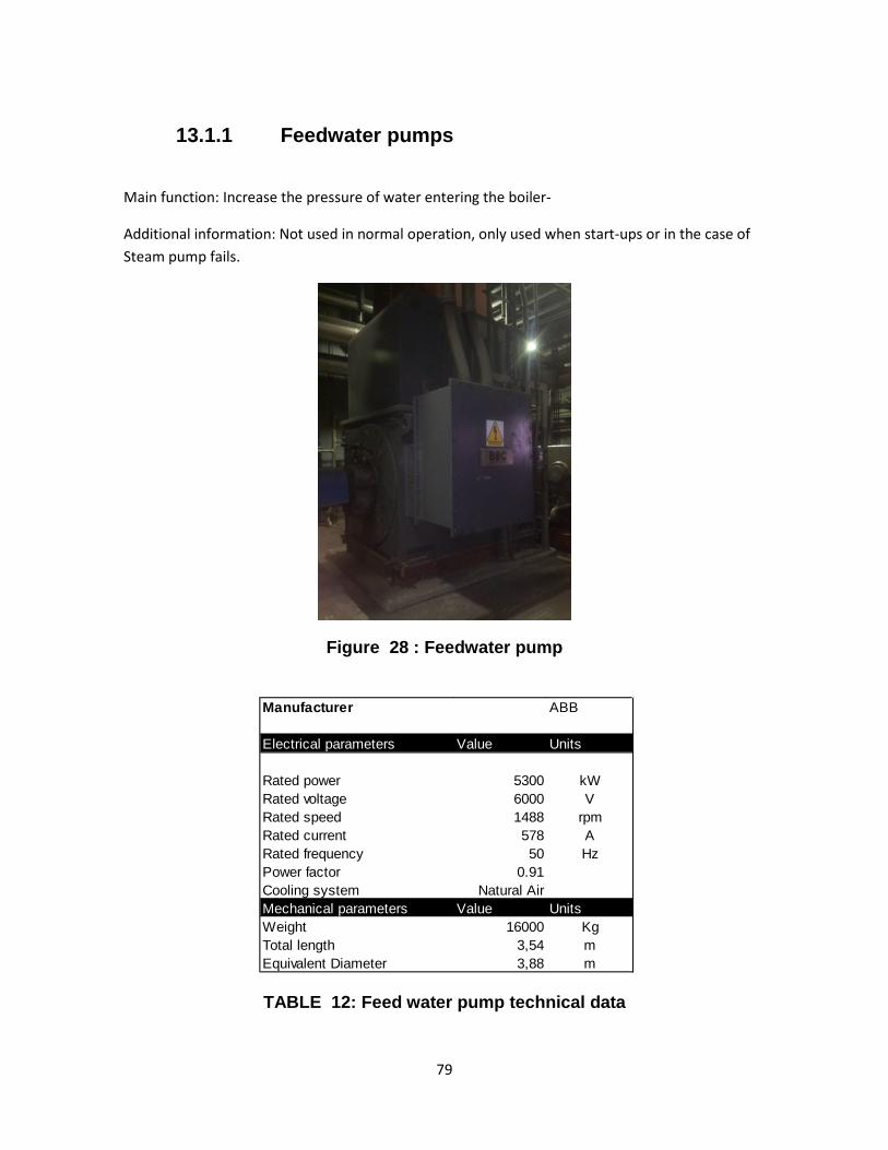
13.1.1 Feedwater pumps
Main function: Increase the pressure of water entering the boiler-
Additional information: Not used in normal operation, only used when start-ups or in the case of Steam pump fails.
Figure 28 : Feedwater pump
TABLE 12: Feed water pump technical data
Manufacturer ABB
Electrical parameters Value Units
Rated power 5300 kWRated voltage 6000 VRated speed 1488 rpmRated current 578 ARated frequency 50 HzPower factor 0.91Cooling system Natural AirMechanical parameters Value UnitsWeight 16000 KgTotal length 3,54 mEquivalent Diameter 3,88 m
79

13.1.2 Condensate pump
Main function: Increase the pressure of water in the condensate cycle.
Figure 29 : Condensate pump
TABLE 13 : Condensate pump technical data
Manufacturer G.E.
Electrical parameters Value Units
Rated power 1070 kWRated voltage 6000 VRated speed 1485 rpmRated current 124,5 ARated frequency 50 HzPower factor 0,87Cooling system Natural AirMechanical parameters Value UnitsWeight 4550 KgTotal length 2,42 mEquivalent Diameter 1,8 m
80
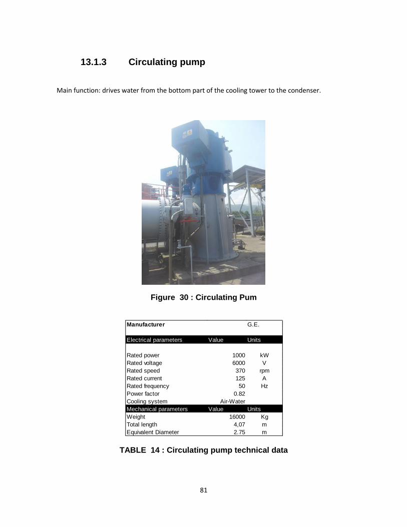
13.1.3 Circulating pump
Main function: drives water from the bottom part of the cooling tower to the condenser.
Figure 30 : Circulating Pum
TABLE 14 : Circulating pump technical data
Manufacturer G.E.
Electrical parameters Value Units
Rated power 1000 kWRated voltage 6000 VRated speed 370 rpmRated current 125 ARated frequency 50 HzPower factor 0.82Cooling system Air-WaterMechanical parameters Value UnitsWeight 16000 KgTotal length 4,07 mEquivalent Diameter 2.75 m
81

13.1.4 Boiler recirculation pump
Main function: Drive the colder water in the boiler, through the furnace for increasing the temperature of this water.
Figure 31: Boiler recirculation pump
TABLE 15: Boiler recirculation pump technical data
Manufacturer Westinhouse
Electrical parameters Value Units
Rated power 191 kWRated voltage 6000 VRated speed 1483 rpmRated current 26 ARated frequency 50 HzPower factor 0.87Cooling system Air-WaterMechanical parameters Value UnitsWeight 1540 KgTotal length 1,34 mEquivalent Diameter 0,65 m
82

13.1.5 Grinder
Main function: Grind the raw material and make it small grains for improving the burning efficiency.
Figure 32 : Grinder
TABLE 16 : Grinder Technical data
Manufacturer G.E.
Electrical parameters Value Units
Rated power 498 kWRated voltage 6000 VRated speed 585 rpmRated current 71.5 ARated frequency 50 HzPower factor 0.72Cooling system AirMechanical parameters Value UnitsWeight 6750 KgTotal length 2,6 mEquivalent Diameter 1,8 m
83
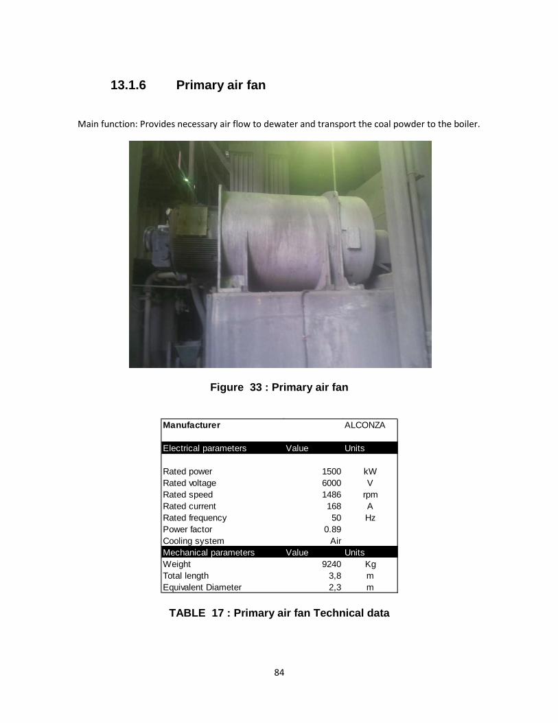
13.1.6 Primary air fan
Main function: Provides necessary air flow to dewater and transport the coal powder to the boiler.
Figure 33 : Primary air fan
TABLE 17 : Primary air fan Technical data
Manufacturer ALCONZA
Electrical parameters Value Units
Rated power 1500 kWRated voltage 6000 VRated speed 1486 rpmRated current 168 ARated frequency 50 HzPower factor 0.89Cooling system AirMechanical parameters Value UnitsWeight 9240 KgTotal length 3,8 mEquivalent Diameter 2,3 m
84
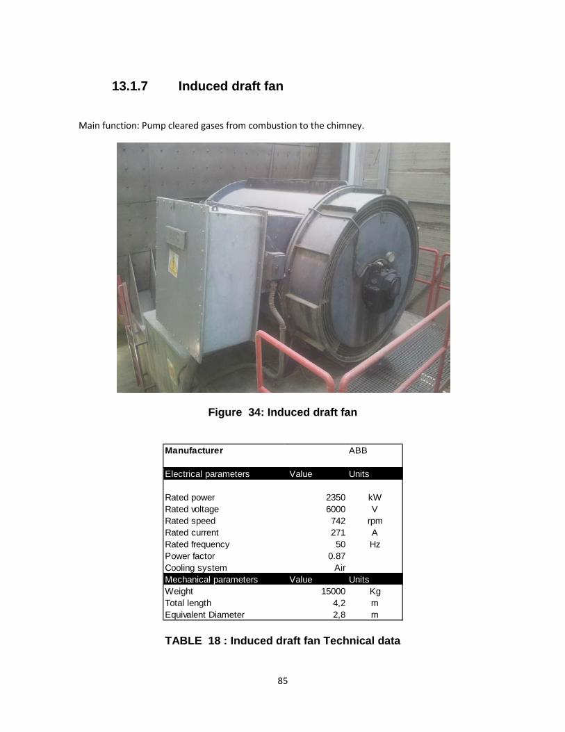
13.1.7 Induced draft fan
Main function: Pump cleared gases from combustion to the chimney.
Figure 34: Induced draft fan
TABLE 18 : Induced draft fan Technical data
Manufacturer ABB
Electrical parameters Value Units
Rated power 2350 kWRated voltage 6000 VRated speed 742 rpmRated current 271 ARated frequency 50 HzPower factor 0.87Cooling system AirMechanical parameters Value UnitsWeight 15000 KgTotal length 4,2 mEquivalent Diameter 2,8 m
85

13.1.8 Forced draft fan
Main function: Introducing the required air for reaching and optimal coal combustion in the boiler
.
Figure 35 :Forced draft fan
TABLE 19 : Forced draft fan technical data
Manufacturer ABB
Electrical paraValue Units
Rated power 930 kWRated voltage 6000 VRated speed 1490 rpmRated current 103 ARated frequen 50 HzPower factor 0.91Cooling syste AirMechanical p Value UnitsWeight 6500 KgTotal length 2,3 mEquivalent Dia 1,6 m
86
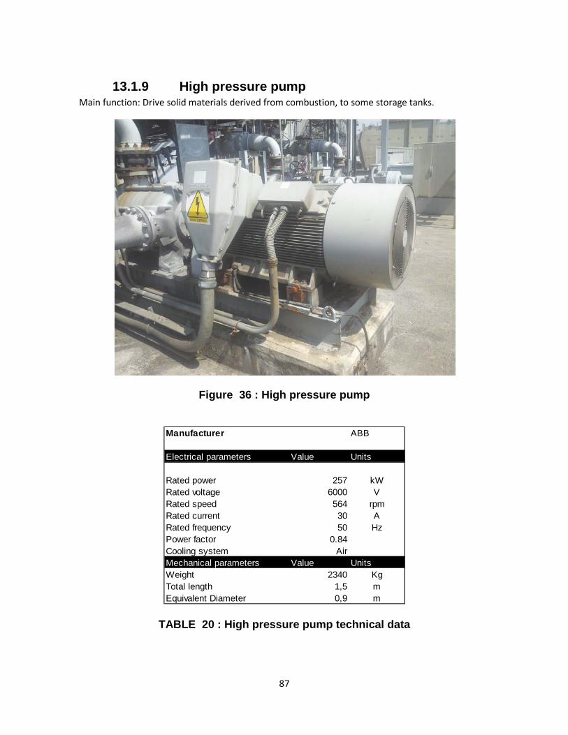
13.1.9 High pressure pump Main function: Drive solid materials derived from combustion, to some storage tanks.
Figure 36 : High pressure pump
TABLE 20 : High pressure pump technical data
Manufacturer ABB
Electrical parameters Value Units
Rated power 257 kWRated voltage 6000 VRated speed 564 rpmRated current 30 ARated frequency 50 HzPower factor 0.84Cooling system AirMechanical parameters Value UnitsWeight 2340 KgTotal length 1,5 mEquivalent Diameter 0,9 m
87
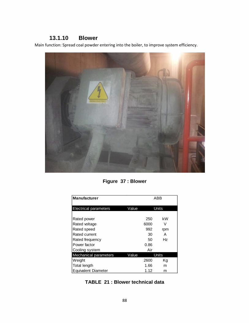
13.1.10 Blower Main function: Spread coal powder entering into the boiler, to improve system efficiency.
Figure 37 : Blower
TABLE 21 : Blower technical data
Manufacturer ABB
Electrical parameters Value Units
Rated power 250 kWRated voltage 6000 VRated speed 992 rpmRated current 30 ARated frequency 50 HzPower factor 0.86Cooling system AirMechanical parameters Value UnitsWeight 2600 KgTotal length 1.66 mEquivalent Diameter 1.12 m
88