master of science university of north …/67531/metadc822801/m2/1/high...preliminary analysis of an...
TRANSCRIPT
PRELIMINARY ANALYSIS OF AN INNOVATIVE ROTARY DISPLACER STIRLING
ENGINE
AmirHossein Bagheri
Thesis Prepared for the Degree of
MASTER OF SCIENCE
UNIVERSITY OF NORTH TEXAS
2015
Bagheri, AmirHossein. Preliminary Analysis of an Innovative Rotary Displacer Stirling
Engine. Master of Science (Engineering Technology- Mechanical Systems ), December 2015, 53
pp., 5 tables, 29 figures, references, 27 titles.
Stirling engines are an external combustion heat engine that converts thermal energy into
mechanical work that a closed cycle is run by cyclic compression and expansion of a work fluid
(commonly air or Helium) in which, the working fluid interacts with a heat source and a heat sink
and produces net work. The engine is based on the Stirling cycle which is a subset of the Carnot
cycle. The Stirling cycle has recently been receiving renewed interest due to some of its key
inherent advantages. In particular, the ability to operate with any form of heat source (including
external combustion, flue gases, alternative (biomass, solar, geothermal) energy) provides Stirling
engines a great flexibility and potential benefits since it is convinced as engines running with
external heat sources. However, several aspects of traditional Stirling engine configurations
(namely, the Alpha, Beta, and Gamma), specifically complexity of design, high cost, and relatively
low power to size and power to volume ratios, limited their widespread applications to date. This
study focuses on an innovative Stirling engine configuration that features a rotary displacer (as
opposed to common reciprocating displacers), and aims to utilize analytical and numerical analysis
to gain insights on its operation parameters. The results are expected to provide useful design
guidelines towards optimization.
The present study starts with an overview of the Stirling cycle and Stirling engines
including both traditional and innovative rotary displacer configurations, and their major
advantages and disadvantages. The first approach considers an ideal analytical model and
implements the well-known Schmidt analysis assumptions for the rotary displacer Stirling engine
to define the effects of major design and operation parameters on the performance. The

analytical model resulted in identifying major variables that could affect the engine performance
(such as the dead volume spaces, temperature ratios and the leading phase angle). It was shown
that the dead volume could have a drastic effect over the engine performance and the optimum
phase angle of the engine is 90o. The second approach considers a non-ideal analytical model and
aims to identify and account the main sources of energy losses in the cycle to better represent the
engine performance. The study showed that the ideal efficiency and the non-ideal efficiency
could have 15% difference that could have as an enormous effect on the engine performance.

Copyright 2015
by
AmirHossein Bagheri
ii

ACKNOWLEDGEMENT
To my beloved parents, sisters, their sons and their husbands and to those who are always
concerned of me.
iii

iv
Table of Contents
1 INTRODUCTION ............................................................................................................ 1
1.1 Motivation ................................................................................................................. 1
1.2 Objectives ................................................................................................................. 2
1.3 Approach ................................................................................................................... 3
2 LITERATURE REVIEW ................................................................................................. 4
2.1 An Overview of the Stirling Cycle and Engines ....................................................... 4
2.1.1 Stirling Cycle ..................................................................................................... 4
2.1.2 Stirling Engines ................................................................................................. 5
2.1.3 Traditional Stirling Engine Configurations ....................................................... 8
2.1.4 Rotary Displacer Stirling Engine Configuration ............................................. 12
2.2 Past and Recent Studies .......................................................................................... 17
3 ANALYTICAL METHODS .......................................................................................... 20
3.1 Ideal Analytical Model ........................................................................................... 20

v
3.2 Non-Ideal Analytical Model ................................................................................... 30
4 RESULTS AND DISCUSSIONS .................................................................................. 36
4.1 Ideal Analytical Model ........................................................................................... 36
4.2 Non-Ideal Analytical Model ................................................................................... 44
5 CONCLUSIONS ............................................................................................................ 50
5.1 Remarks .................................................................................................................. 50
5.2 Recommendations for Future Work........................................................................ 51
REFERENCES ............................................................................................................................. 52

vi
List of Figures
Figure 2-1: A Stirling cycle processes [3]. ..................................................................................... 5
Figure 2-2: Major components of the Alpha configuration of a Stirling engine [1]. ...................... 9
Figure 2-3: The Beta configuration of Stirling engines [1]. ......................................................... 10
Figure 2-4: The Gamma configuration of Stirling engines [1]. .................................................... 11
Figure 2-5: Major components of a Rotary Displacer Stirling Engine in exploded view. ........... 13
Figure 2-6: Halved view of the displacer housing. ....................................................................... 14
Figure 2-7: Segment schema. ........................................................................................................ 15
Figure 2-8: Displacer housing filled with segments. .................................................................... 15
Figure 2-9: Rotary displacer Stirling engine valve mechanism. ................................................... 16
Figure 3-1: Schematic design of Stirling engines with rotary displacers ..................................... 21
Figure 3-2: Pressure volume schematic diagram. ......................................................................... 29
Figure 3-3. The schematic of a Stirling engine considering losses {Formosa, 2010 #116}. ........ 30
Figure 3-4. General scheme of a rotary displacer Stirling engine. ............................................... 31

vii
Figure 3-5. The simple mechanism of a power piston. ................................................................. 33
Figure 4-1. Volume vs. crank shaft angle during one completed cycle. ....................................... 37
Figure 4-2. Pressure vs. crank shaft angle for one complete cycle when Tc = 373 K and Th = 923
K. ................................................................................................................................................... 38
Figure 4-3. Pressure vs Volume at different phase angles when Tc = 373 K and Th = 923 K. ..... 40
Figure 4-4. Comparison between P-V diagrams of the prototype for different hot side
temperatures at a constant cold side temperature (373 K) and phase angle of 90o. ...................... 40
Figure 4-5. Generated work comparison with the phase angle at different values of temperature
ratio and cold side temperature of 323 K. ..................................................................................... 41
Figure 4-6. Generated work vs. temperature ratio at different cold side and hot side temperatures
at the phase angle of 90o ............................................................................................................... 42
Figure 4-7. Work ratio vs shuttled volume ratio at different dead volume ratios at
and . ........................................................................................................................... 44
Figure 4-8. Reynolds variation vs. frequency in the connecting ports. ........................................ 46
Figure 4-9. Pressure drop over the mean pressure vs. temperature ratio at different frequencies. 47
Figure 4-10. Output power vs. Temperature ratio at different frequencies when . . 48

viii
Figure 4-11. Mechanical efficiency vs. Temperature ratio at different frequencies when
. ......................................................................................................................................... 49

ix
List of Tables
Table 4-1. Geometrical features of the prototype engine. ............................................................ 36
Table 4-2. Volume ratios of the prototype engine. ....................................................................... 36
Table 4-3. Assumed operating conditions for the engine . ........................................................... 37
Table 4-4. The specifications of the engine prototype. ................................................................. 44
Table 4-5. Computed inner temperatures of displacer housing .................................................... 45

1 | P a g e
1 INTRODUCTION
This chapter describes the motivation, objectives, and the technical approach to provide a brief
introduction to this study.
1.1 Motivation
Stirling engines are convinced as having one of the most complicated cycles in
thermodynamics systems whereby despite they have the closest efficiency to the ideal Carnot
cycles, they have not reached an appropriate position in terms of applications. Therefore, it seems
imperative to study and implement these particular engines more accurately. Achieving a higher
efficiency has always been remained a great challenge to engineers. With all advances and
improvements in thermodynamics and machinery, most of the generated heat in thermodynamic
cycles is still wasted. More energy captivated would result in lower cost for end users, less
contamination for environment, and saving resources for future generations. Therefore, it is very
appealing to focus on this topic and attempt to improve energy conversion methods or captivate
waste energy.
In 2013, Dr. Philip Foster from University of North Texas patented a new Stirling engine
configuration [1]. The geometry seems to be interesting based on very design and manufacturing
because of the existence of an innovative part; the rotary displacer in which, the constant-volume
processes of the Stirling cycle which is done by a reciprocating part in other configurations, is
performed. The most interesting parts of this engine are rotary segments installed in the displacer
housing that are not in touch with the body and pass with a few thousands of inches clearance.
This would lead to have no friction whatsoever. Albeit, Stirling engines are known of having low

2 | P a g e
efficiency (normally 15%), however the new configuration proves the concept of existence of a
Stirling engine, running at small temperature difference (around 20oC) at the low values of
temperature and proving the capability of this new configuration. Consequently, it is imperative
for the configuration to be studied deeper.
1.2 Objectives
The major objectives of this study are to: (i) present preliminary analytical models for the
rotary displacer Stirling engine concept, and (ii) study the major parameters that could affect the
engine design and performance. The models involved two approaches, an ideal and a non-ideal
analytical approach.
The ideal analytical model suggests the initial steps for any given conditions and estimates
the engine output based on the overall mechanism, without considering each engine
component individually. This analysis assumes multiple ideal facts, originally introduced
by Schmidt (or isothermal) analysis, and is not very realistic. However, it considers the
reciprocating nature of the engine and also the so-called “lead phase angle”, and is capable
of depicting the cycle. Thus this analysis provides helpful insights on engine parameters at
early stages of design effort.
The non-ideal analytical model aims a more realistic model by taking significant energy
losses through various engine components into consideration. Therefore this approach,
compared to ideal analytical model, provides a much better tool for design purposes.
However, several aspects of the cycle irreversibilities are still not captured and require
further studies.

3 | P a g e
1.3 Approach
As the first taken, the ideal condition for the engine is studied and the governing equations
are written over it. Since there is an existing prototype which can operate, the prototype
specifications are taken to the model and results are presented in tabular and figures. It is attempted
to capture the engine harmonic motion and effect of some known variables on the performance.
Finally, it is managed to identify constraints even in the ideal condition. Assuming the ideal gas
condition and sinusoidal movement of the power piston help to implement the task.
The other approach is looking at the configuration through a non-ideal perspective in which,
the configuration is studied in a discrete perspective; each part is considered as an overall system
but the combination of them are studied individually. Another words, the thermodynamics laws
are written for each part entry and exit. It is assumed that the engine operates at adiabatic non-
reversible condition. This method has been vastly used by other researchers for other
configurations. Thus, in this particular configuration, the method is adopted and accommodated.
Some ideal assumptions are still used but it will be justified why they are considered. In the end,
results are compared with the ideal analysis.

4 | P a g e
2 LITERATURE REVIEW
In this chapter, a short review of Stirling Cycle, Engines and available configurations are
presented. Then the audience is provided with the concept of “Stirling Engine with Rotary
Displacers” and its advantages and after all, the objectives of this thesis and their significant roles
are illustrated.
2.1 An Overview of the Stirling Cycle and Engines
In this section, it is aimed to have a glance at the Stirling cycle and the traditional and the
new patented Stirling engine configurations.
2.1.1 Stirling Cycle
The Stirling cycle is a thermodynamic cycle invented by Robert Stirling in 1816 [2]. The
Stirling cycle that is based on the Carnot cycle consists of two isentropic and two constant-volume
processes. The major specifications of this cycle are:
Closed-cycle
Reversible
In Figure 2-1, the p-v and T-s diagrams of an ideal Stirling cycle are shown. The cycle starts at
point 1 (process 1-2) in which the working fluid volume (subsequently the pressure) decreases
through a constant temperature process. In this process, the entropy is also declined. Then in
process 2-3, a specific amount of head is added up to the working fluid whereby the working fluid
entropy and temperature increase but the volume remains constant. In process 3-4, the working
fluid volume and pressure are increased via an isentropic process. In the end, in process 4-1, the

5 | P a g e
heat is rejected from the working fluid through a constant volume process, the pressure goes down
and the cycle completes.
Figure 2-1: A Stirling cycle processes [3].
The ideal Stirling cycle efficiency is equal to the Carnot cycle efficiency:
(1)
Obviously eq. (1), cannot be applied to real cycles since there are no Carnot cycles but it
provides the concept of Stirling cycles. In the next section, Stirling engines are briefed.
2.1.2 Stirling Engines
As described in section 2.1, Stirling engines are based on the Stirling cycle. Stirling engines
are heat engines that convert heat energy to mechanical work via the Stirling cycles which were
discussed [4]. As it was shown in Figure 2-1, the four main processes are:

6 | P a g e
1- Isothermal compression
2- Constant-volume heat addition
3- Isothermal expansion
4- Constant-volume heat removal
The most significant characteristic of this particular engine is known as having at least one
piston that does the compression and expansion of the working fluid processes. It also operates
with an external heat source which is convinced as an advantage of this engine. In the following,
the advantages and disadvantages of this engine are presented.
2.1.2.1 Advantages
The advantages of Stirling engines are briefed as following:
Using external heat source
This engine could easily operate with any type of heat resources including solar,
biological or nuclear sources. So it may be used for energy recovery goals.
Using a single-phase working fluid
Changing phase of the working fluid in a cycle could lead to explosions that in Stirling
engines are lower statistically. In addition, the internal pressure gets closer to the design
pressure.
Operating in various weathers and easily start-up in cold weathers.
No internal combustion in pistons
Internal combustion creates corrosion and other structural failures that increases the
engine unreliability.

7 | P a g e
Simpler configuration than reciprocating engines
This engine has simpler configurations because of the valve mechanism and
reciprocating movements in internal combustion engines which make the system more
complex.
2.1.2.2 Disadvantages
Stirling engines are commonly known as having the following disadvantages:
Choosing proper working fluid
Finding the proper gas for this cycle which could be expanded and compressed without
damaging the engine is one the major issues with this engine. There are numbers of studies
over the issue carried out by researchers and scientist.
Size and weight issues
Because of the nature of Stirling engines, usually they weight more than other heat
engines. The cycle requires the components to stay in touch with the highest temperature
of the cycle like Gas turbine engine because the working fluid is conducted through the
engine. In contrast, in the Otto and the Diesel cycles, the working-fluid temperature reaches
more than the component limits that gives the option of choosing a wide range of cheap
materials and also, imposes metallurgical limitations. In addition, in order to increase the
efficiency, the coolant temperature must be kept as low as possible that leads to having
larger radiators.
Power issues
An important factor of representing an engine is the Power to Weight ratio and in
comparison with other engines, it is much higher. Also the amount of heat flux delivered

8 | P a g e
to the working fluid is much smaller than other engines. In addition of all these problems,
Stirling engines require higher “warm-up” time than other cycles.
2.1.3 Traditional Stirling Engine Configurations
Every Stirling engine follows the Stirling cycle. Another word, it should have one hot side and
one cold side that the cycle is implied to. There are three configurations of Stirling engines which
were innovated and studied which are:
1- Alpha
2- Beta
3- Gamma
In this section, a brief of each configuration and their advantages and disadvantages are
represented.
2.1.3.1 Alpha Stirling Engine
The Alpha configuration consists of two pistons, a hot and a cold cylinder that the working
fluid (normally gaseous) is driven between them. The pistons are joined with a crankshaft with the
certain degree of phase angle (usually 90o). Figure 2-2 displays a simple configuration of the Alpha
configuration. It is also the first configuration of Stirling engines

9 | P a g e
Figure 2-2: Major components of the Alpha configuration of a Stirling engine [1].
Advantages
Simplicity
High power to volume
Disadvantages
Five moving parts per power cylinder
Close tolerance fit in the hot workspace (i.e., the hot cylinder and hot power piston)
presents problems in maintaining a reliable seal
Designs that eliminate hot piston seal failure tend to increase engine dead space
Limited surface area for heat transfer in the hot workspace.

10 | P a g e
2.1.3.2 Beta Stirling Engine
The Beta configuration is more complex but smaller than the Alpha configuration. It has one
power piston arranged with the same cylinder on the same shaft as a displacer piston. Figure 2-3
shows the Beta configuration. As it is shows, the hot workspace is at the end of the cylinder while
the cold workspace is close to the beginning. Both pistons are connected to a crankshaft with
different lengths and phase angles.
Figure 2-3: The Beta configuration of Stirling engines [5].
The idea of designing this configuration was to minimize the dead space and make the engine
smaller but at the same time, it added more complexity to the engine itself. In brief, the advantages
and disadvantages of Beta configuration would be:
11 | P a g e
Advantages
Use of a displacer eliminates hot seal failure issues of the Alpha in engine hot workspace.
The Beta minimizes dead space rather than the Alpha
Disadvantages
Five moving parts per power cylinder.
Limited surface area for heat transfer in the hot workspace.
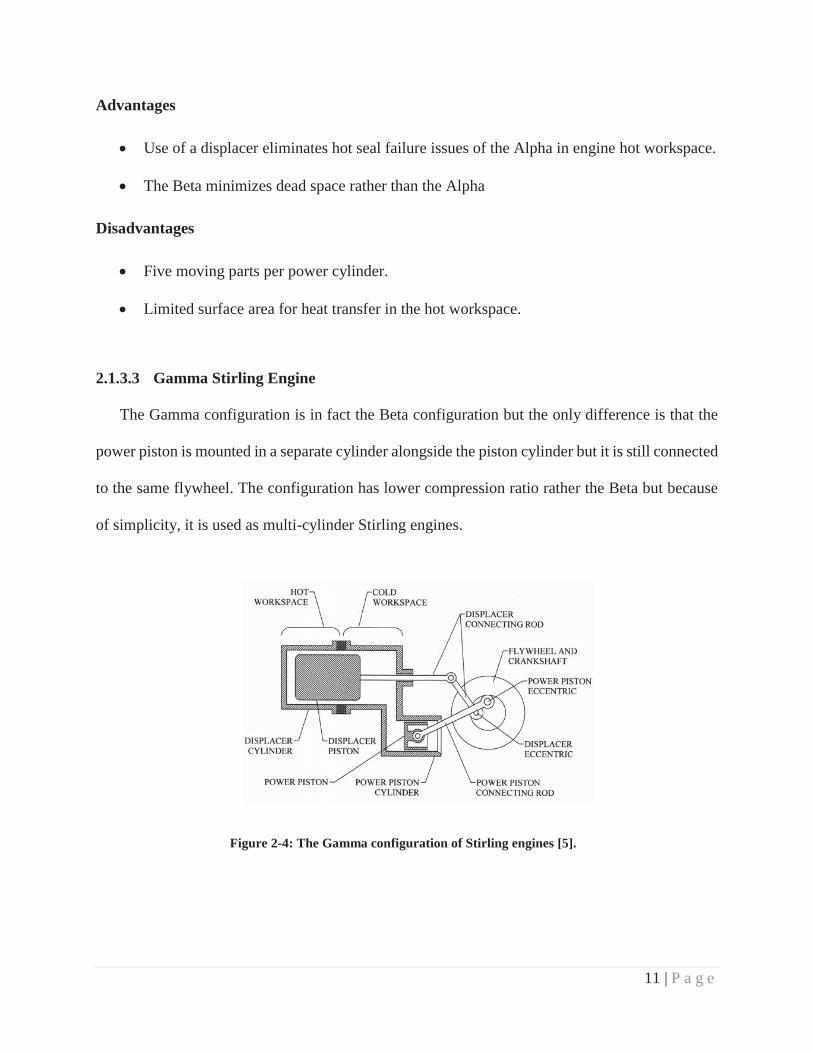
2.1.3.3 Gamma Stirling Engine
The Gamma configuration is in fact the Beta configuration but the only difference is that the
power piston is mounted in a separate cylinder alongside the piston cylinder but it is still connected
to the same flywheel. The configuration has lower compression ratio rather the Beta but because
of simplicity, it is used as multi-cylinder Stirling engines.
Figure 2-4: The Gamma configuration of Stirling engines [5].

12 | P a g e
The idea behind the Gamma configuration was to simplify the Beta configuration but since it
has a low compression-ratio, it cannot be widely used in the industry. In brief, here are advantages
and disadvantages of the Gamma configuration:
Advantages
Higher thermal efficiency in comparison with other engines.
It is safer than the Beta configuration.
Disadvantages
Lower power output per piston and displacer.
Limited surface area in hot workspace for heat transfer
Five moving parts per power cylinder.
In conclusion, despite of all advantages of Stirling engines, this engine cannot be used vastly
as it is expected. There are some challenging issues with this engine which need to be solved:
Engine Size
Displacer performance
Friction in Pistons
2.1.4 Rotary Displacer Stirling Engine Configuration
In 2013, Dr. Philip Foster from University of North Texas patented a new design of Stirling
engine in which he replaced the traditional displacer with a rotary displacer. In brief, the engine
configuration can be briefed as following:
A rotary displacer unit
A power piston
A connecting rod

13 | P a g e
The rotary displacer performs the cycle constant-volume heat addition and heat removal, the
power piston does the isothermal expansion and compression and the connecting rod connects the
displacer and power piston and also transmits power among them. A simple configuration of this
new model is shown in Figure 2-5. The cycle starts with an adiabatic compression when the piston
contracts and is pushed forward. Then it goes into the displacer housing and through a constant-
volume process, heat is added to the working-fluid. Then it travels to the piston and through an
adiabatic process, the working fluid expands. After all, the working fluid goes to the displacer
housing cold side and heat is removed from it.
Figure 2-5: Major components of a Rotary Displacer Stirling Engine in exploded view.
The main parts of the displacer housing are:
Housing Hot Side
Housing Cold Side

14 | P a g e
Rotary Displacer Segments
Shaft
The cold side and the hot side must be made of expanding-contracting resistant materials so
they can bear the temperature difference along the displacer and remains connected while the
engine operates. Grooves are built into the inner side so segments can be fit and move easily. The
hot side and the cold side are separated from each other by a thermal isolator (Figure 2-6). Rotary
displacer segments are embedded inside the displacer. They have a missing volume at the very top
that traps the working-fluid there and the other side fits into the grooves inside the displacer and
sweeps the displacer inner surface (Figure 2-7).
Figure 2-6: Halved view of the displacer housing.

15 | P a g e
Figure 2-7: A unit segment.
The filled displacer housing is shown in Figure 2-8. As it clear from the hot side, the cold side
port is closed by the segments and port is open to the hot side. The valve mechanism of this engine
is operated by segment #1. Another word, when segment 1 rotates, it opens and closes ports for a
very small portion of a full cycle time and there is only small amount of overlapping. (Figure 2-9)
Figure 2-8: Displacer housing with inserted segments.

16 | P a g e
Figure 2-9: Rotary displacer Stirling engine valve mechanism.
2.1.4.1 Advantages of Rotary displacer Stirling Engine Configurations
The main part that is innovative in this engine is the rotary displacer therefore it is needed to
illustrate the advantages of rotary displacer.
The displacer never changes direction.
In contrast to traditional Stirling engines, the rotary displacer does not have a back and
forth movement. The back and forth movement may cause unreliability, more friction and
less durability. Also it requires more power to run and adds more complexity to the engine.
So it would have positive impact on the engine performance and efficiency.
Simpler design.
Foster Stirling engines are simpler than other Stirling engines. This simplicity is caused
because of each component runs individually independently.
More heat transfer area available to the working fluid.

17 | P a g e
The most challenging part in every thermodynamic cycle is adding or removal heat
from the working fluid when the cycle runs. In traditional Stirling engines, because of
constraints over the piston volume, there was a certain limitation over the amount of
added/removed heat to the working fluid. The large surface of displacer housing provides
adequate capacity for the working fluid to absorb or reject heat.
No hot or sliding seals contact the displacer.
In traditional Stirling engines, since the engine was too complicated, the constant
volume processes are interrupted but in this engine, the displacer operates independently
well-enough far from the process and once every process is completed, the following
process begins.
All loads on the displacer (radial and thrust) are accommodated by ball and/or rolling
bearings.
2.2 Past and Recent Studies
One of the most sophisticated theoretical analyses over Stirling engine was represented by
Gustav Schmidt in 1816 [2]. He is convinced as the first person giving a theoretical solution for
the harmonic motion of Stirling engines. In practice, the performance could not reach more than
60 percent of the ideal Schmidt cycle [6]. In 1960, Finkelstein gave an adiabatic analysis in which,
he considered the compression and the expansion processes non-isothermal that could depict a
more realistic picture [7]. In 1997, Israel Urieli provided the nodal analysis which was considered
the most comprehensive and complete discussion over of Stirling engine simulation [8]. That was
the first simulation considering pressure loss in the regenerator presenting a highly accurate
estimation of Stirling engines. William Beale of University of Ohio offered estimation over the
Stirling engine performance in 1960 [9]. He also presented the Beal number concept which was

18 | P a g e
found out that is approximately true for all types and sizes of Stirling engines. Typical values of
the Beale number varies between 0.011 and 0.015 and the more value offers the more performance
[9]. However the Beale number does not include temperature. Therefore, the West number was
presented in 1981 that includes temperature compensation. The range would be between 0.25 and
0.35 [10] which was later confirmed by Senft [11], Iwamoto [12] and Prieto [13]. The West
equation is a guideline to estimate the engine size for a given value of power output. Kolin
described a “rule of thumb” for approximating the ideal volume ratio which depends on
temperature difference of the engine [14]. Also he suggested that the best phase angle would not
be necessarily 90o. In addition, another type of Stirling engine was invented which is called “Free
piston” Stirling engines by Beale in 1960 [9]. In this design, energy may be added or removed by
an electrical linear alternator, pump or other coaxial device.
Organ published a comprehensive textbook over Stirling engines on 2007, presenting various
aspects of them. He also discussed the effect of regenerators over Stirling engines and reviewed a
commercial engine named “GPU-3” [15]. Besides, he derived non-ideal equations for a Stirling
engine. In 2004, Kongtragool and Wongwises studied gamma-configuration low temperature
differential Stirling engines and proved that among all theoretical presented analysis, the mean
pressure formula would give a better estimation than others [16]. In 2007, Senft provided the
central theorem in which, he tried to demonstrate the relation between the temperature ratios and
the mechanical effectiveness [17]. He also calculated the amount of pressure drop in a Stirling
engine and its effect on the overall performance. In 2009, Lloyd from University of Canterbury
and his team came up with a new design of a Stirling engine featuring a rotating displacer which
is actuated by a pair of stepper motors. The rotating displacer has the capability of simple and
cheap manufacturing and also avoids problems such as sealing and heat loss [18]. In 2009, Parlak

19 | P a g e
and coworkers conducted a research over a gamma type Stirling engine assuming a quasi-steady
flow model based on Urieli and Berchowitz’ works by implementing a FORTRAN® code [19].
They managed to compute the thermal efficiency. However, there was a lack of experimental
validation in their work. Formosa and Despesse presented an analytical model for Stirling engines
by studying a free piston configuration; the “GPU-3”® model and came up with a high accurate
model for regenerators. Their work was based on the Schmidt analysis and by recalling the Senft
central theorem, they managed to identify all irreversibly factors and took them in to account [20].
Finally, they optimized some variables including effect of the fluid mass, regenerator length and
regenerator thermal conductivity. In 2013, Kwankaomenga, Silpsakoolsook and Savangvong
suggested that the stable operation of a free-piston Stirling engine is achieved when both engine
configuration and operation conditions are optimized and conducted an investigation over it [21].
They also built a prototype and tested the device and concluded which was heated by an electric
heater and cooled by air. In 2014, Hoegel from University of Canterbury completed his college
work and proved that the engine is suitable for running at low temperatures [22]. He also proved
the concept of Stirling engine usage in low temperature difference which could be beneficial for
harvesting waste heat.

20 | P a g e
3 ANALYTICAL METHODS
This chapter aims to present an ideal and non-ideal model in order to depict a clear picture of
rotary displacer Stirling engines. First, it is managed to approach to the configuration considering
ideal conditions in which, no friction or loss is considered. Then, by identifying major sources of
losses in the engine, a model is presented to capture those losses.
3.1 Ideal Analytical Model
In this section, a preliminary analytical analysis is utilized to gain insights on the important
parameters of the rotary displacer Stirling engine. This is done by adopting some of the
assumptions from the well-known Schmidt analysis, and by following a similar approach for the
innovative rotary displacer configuration. In addition, important variables are identified and
subjected to be studied. Maximum phase angle between the power piston and the displacer housing
is calculated that could have a major effect on the engine’s performance. Although this preliminary
analysis considers the ideal conditions for Stirling engines and does not include any irreversibility,
it could still be utilized as the initial step to comprehend the engine characteristics. Main parts of
the engine are shown in Figure 3-1. The working fluid travels between the displacer housing and
the power piston through two connecting pipes and the displacer housing is attached to the power
piston through an intermediary; the crank shaft and the reference point for all equations is set from
the shaft. Prior to the analysis, the Schmidt analysis assumptions are reviewed:
1- There is no heat loss in the engine.
2- There is no leakage in the entire engine.
3- The working fluid follows the idea gas equation of state ( ).

21 | P a g e
4- The expansion and compression processes occur isothermally.
5- There is no pressure drop in the cycle as it neglects the friction.
6- Pressure is the same across the entire enclosure.
As it is shown in Figure 3-1, the working fluid mass is given and constant.
Figure 3-1: Schematic design of Stirling engines with rotary displacers
Since the mass of working fluid is always constant in the entire engine, eq. (2) can be written
as:
(2)
Where is the overall mass of the working fluid inside the enclosure, is the mass of
working fluid inside the displacer housing (shuttled volume), is the mass of working fluid

22 | P a g e
in the cold side connecting pipe, is the mass of the working fluid inside the hot side
connecting pipe and is the mass of working fluid in the power piston (displaced volume). The
ideal gas equation ( ) will help up to implement the approach. Considering the ideal gas
relation (which is mostly accurate) and assuming the physical fact of Newtonian fluids (Pressure
is the same along the enclosure), the following equation can be derived:
In which is the shuttled volume, is the working fluid temperature in the shuttled
volume, is the displaced volume, is the temperature of displaced volume, is the volume
of hot side connecting pipe, is the fluid temperature inside the hot side connecting pipe,
is the volume of the cold side connecting pipe and is the fluid temperature inside the cold side
connecting pipe. The shuttled volume ( ) that remains constant during the entire cycle, consists
of two volumes that varies:
(3)
Where is the volume faces the cold side and is the volume that faces the hot side.
Consider the phase angle of the cold side shuttled volume ( ) is described as a function of
the crank angle ( ). (eq. (4))
(4)

23 | P a g e
And the hot side shuttled volume is obtained from eq. (5):
(5)
The analysis considers the same values of temperature at the hot side and the cold side dead
volumes, thus the amount of dead volumes can be integrated as eq. (6):
(6)
In which is the overall dead volume. Also the displaced volume motion can be explained
as eq. (7).
(7)
In which is the maximum swept volume by the power piston. So the overall volume is
described in eq. (8) in which is the overall volume.
(8)
In the Schmidt analysis, the fluid volume in each part is compared with the swept volume ( ).
The reason lies in the approach to thermodynamic cycles and the work definition; a displacement

24 | P a g e
must happen to produce work [3]. In Stirling engines, the power piston does the work and if it does
not move, there will be no work. The volume ratio is described as eq. (9).
(9)
In which is the shuttled volume, is the total amount of dead volumes, and is the
swept volume. In the Schmidt analysis, it is assumed that the temperature distribution along each
engine component remains constant. However, due to the nature of the current geometry, featuring
a rotary displacer where the heater and cooler spaces for the shuttled working volume vary, this
assumption may not be applied. Thus, according to eq. (9), when the crank shaft angle, ( equals
, the shuttled volume faces the cold side, and when it is equal to , it faces the hot side
volume. Assuming the ideal condition that the provided heat is fully transferred to the working
fluid, it can be assumed that the temperature of the shuttled volume in the displacer housing can
be described in a periodic function of the cold side and the hot side temperature (eq. (10)). Besides,
it is presumed that the fluid temperature in the connecting pipes and the power piston is equal to
the average temperature of the hot and cold sides of displacer housing (eq. (11)).
(10)
(11)

25 | P a g e
represents the displacer housing heat source temperature and represents the displacer
housing heat sink temperature. Another important variable in Stirling engines is the temperature
ratio ( ) as defined in eq. (12).
(12)
(13)
By defining eq. (14),
(14)
Eq. (13) is changed to
(15)
Or

26 | P a g e
(16)
From trigonometric relationships (eq. (17)),
(17)
Eq. (6) is written as the following and try to simplify it.
By recalling trigonometric relationships (eq. (18), eq. (19), eq. (20)),
(18)
(19)
(20)

27 | P a g e
Eq. (6) is turned to:
(21)
Or
(22)
Where
So eq. (16) is re-written as:
(23)
Where

28 | P a g e
So eq. (23) is turned to
(24)
So the pressure is calculated from the following equation:
(25)
(26)
(27)
(28)
Eq. (28) cannot be solved analytically but it can be solved numerically. Another major issue
that needs to be studied is the maximum lead angle for a given conditions. By drawing pressure-
volume diagram schematically (Figure 3-2), it is noticed that the pressure when must
be always greater than the pressure when .

29 | P a g e
Figure 3-2: Pressure volume schematic diagram.
Thus, it is obtained from eq. (16):
(29)
Inequality (29) must be always satisfied. Therefore, by solving inequality (29) and setting it
equal to zero, the maximum phase angle can obtained:
(30)
Eq. (30) shows that for each given geometry ( ) and operating condition (
), there is a certain limit on the maximum phase angle which is applied to the engine.
30 | P a g e
3.2 Non-Ideal Analytical Model
As mentioned in Chapter 2, there are several analytical models developed by researchers with
high accuracy in order to predict Stirling engines performance and efficiency. These models take
into account the heat losses and irreversibilities of the engine. This section aims to identify the
main sources of losses and study their effect on the engine.
Typically, there are two major losses in the engine:
1. Heat loss
2. Flow friction
These losses previously have been studied in [8], [19] and [20]. In addition, if they are
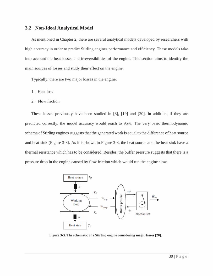
predicted correctly, the model accuracy would reach to 95%. The very basic thermodynamic
schema of Stirling engines suggests that the generated work is equal to the difference of heat source
and heat sink (Figure 3-3). As it is shown in Figure 3-3, the heat source and the heat sink have a
thermal resistance which has to be considered. Besides, the buffer pressure suggests that there is a
pressure drop in the engine caused by flow friction which would run the engine slow.
Figure 3-3. The schematic of a Stirling engine considering major losses [20].

31 | P a g e
Figure 3-4 indicates assigned variables in the current configuration. It shows the heat direction
in both hot side and cold side in which, the concept of the second thermodynamics law implies the
direction of heat. The outer space of the displacer housing has the temperatures of and at the
hot side and cold side respectively. Thus, and represent the inner temperature values of the
hot side and cold side respectively. Due to conduction thermal resistance, the nature of the system
applies the following condition:
Figure 3-4. General scheme of a rotary displacer Stirling engine.
The amount of temperature drop across the displacer housing wall is given by eq. (31) [23]:

32 | P a g e
(31)
In which, is , is the length of displacer housing and is the thermal conductivity of
the body. Therefore, eq. (32) turns to
(32)
In which and are constant values obtained from the boundary conditions. It was assumed
that the displacer housing is in adiabatic condition and temperature only changes along the axis.
In addition, eq. (32) can be applied to the both sides of the displacer housing. Based on Figure 2-6,
it is observed that the port (inlet and outlet) locations are inside the body. Therefore, the working
fluid temperature is assumed as the inner wall temperature at ports. According to the first law of
thermodynamics:
(33)
Where is the enthalpy, is the internal energy, is the system pressure and is the system
volume. By having partial derivate of both side, eq. (33) turns to eq. (34):
(34)
In which, is the change of the internal energy, is the system volume, is the system
pressure and is the work done by the system. Therefore, by computing and , it
will be possible to calculate the amount of work done by the system. (eq. (35)).

33 | P a g e
(35)
Considering the working fluid is an ideal gas, the enthalpy and the internal energy differences
are calculated from eq. (36) and eq. (37).
(36)
(37)
In which is the entire system flow mass, is the temperature difference of the working
fluid and and are the specific heat capacity at constant volume and pressure respectively.
It is assumed that the engine is rotating at a constant frequency; . Based on Figure 3-5, the
swept angle by both connecting crank shaft are always equal to each other. So according to the
basic dynamic of piston-cylinder movement (Figure 3-5), the piston velocity is obtained (eq. (38)
[24]).
Figure 3-5. The simple mechanism of a power piston.

34 | P a g e
(38)
In which, is the engine frequency and is the stroke length. By assuming that the power-
piston does not knock and travels at the constant speed all the time, the incoming and outgoing
working fluids are supposed to have the same flow rate. Therefore, the volumetric flow rate is
equal to:
(39)
Where is the pipe cross section area. By applying eq. (39) to eq. (35) and having the
amount of input energy ( and output energy ( , the amount of thermal efficiency is obtained:
(40)
Senft has also demonstrated a correlation for considering the pressure drop effect. Therefore,
the total mechanical effectiveness is obtained from eq. (41) [17] and eq. (42) [25].
(41)
(42)
Where is pressure drop at the cold side connecting pipes, is pressure drop at the
hot side connecting pipes, is the flow friction factor which varies based on whether the flow is

35 | P a g e
laminar or turbulent, is the pipe length, is the pipe inner diameter, is the flow density and
is the mean velocity at the entire enclosure.

36 | P a g e
4 RESULTS AND DISCUSSIONS
This chapter presents results from both ideal and non-ideal analytical models implemented
earlier into two separate sections and discusses the obtained results to provide practical insights on
the rotary displacer Stirling engine performance.
4.1 Ideal Analytical Model
In order to analyze the results, the very first step is to specify the type of working fluid. In
this study, Helium is chosen because it is known as one of the best affordable commercial working
fluids [26] and the prototype size which has been built by the engine innovator for the engine
geometry. The Helium gas specific constant (R) equals 2076.9 and the engine geometry is
described in Table 4-1.
Table 4-1. Geometrical features of the prototype engine. Name Volume (×10-6 m3) Shuttled Volume 43.75
Piston-Cylinder Swept Volume 8.05 Expansion space dead volume 5.83 Compression space dead volume 2.20
Therefore, the volume ratios are calculated form eq. (9) as shown in Table 4-2.
Table 4-2. Volume ratios of the prototype engine. Volume ratio Value
XDV 0.997 XSh 5.431
It is assumed that the engine is filled with Helium and pressurized ( at room
temperature ( ). So the amount of working fluid is calculated from the ideal gas relation (eq.
(2)) which would be:

37 | P a g e
A MATLAB® code was developed for it and the equations were solved under different
conditions as shown in Table 4-3.
Table 4-3. Assumed operating conditions for the engine at . Cold Side Temperature
(K) Hot Side Temperature
(K) o
373 473 0.7886 0.1182 140.6
373 623 0.5987 0.2510 111.3
373 773 0.4825 0.349 105.2 373 923 0.4041 0.4244 102.4 373 1073 0.3476 0.4841 100.9
The working fluid volume change versus the crank shaft angle ( ) as is shown in Figure 4-1.
As the eq. (8) implies, the volume change solely depends on the geometry and is independent from
all other variables. Perspicuously, the maximum volume is obtained when the piston is fully
expanded and the minimum volume is reached when the piston is fully contracted and the dominant
is the swept volume by the piston.
Figure 4-1. Volume vs. crank shaft angle during one completed cycle.

38 | P a g e
Figure 4-2 shows the engine pressure change with respect the angle of rotation at various
phase angle. In contrast with the volume diagram, it is fully dependent on the amounts of
temperature. Also, it becomes clear that the engine minimum pressure is roughly independent of
the phase angle but indeed, it shifts at different angles. But the maximum pressure value of the
system is affected. The plot indicates that the maximum value is gained when the phase angle is
equal to zero and minimum value is reached when the phase angle is 180o but finding out the
maximum gained pressure at different phase angle is not a good point to judge on the phase angle
but what is significant is the maximum work done by the engine which can be calculated from
Pressure-Volume diagram.
Figure 4-2. Pressure vs. crank shaft angle for one complete cycle when Tc = 373 K and Th = 923 K.
The best figure that may depict the engine performance and efficiency versus phase angle
is the Pressure-Volume diagram which is shown in Figure 4-3 at operating temperature of 373 K
of the cold side and 923 K of the hot side. The figure indicates that for the angle of zero and 180,
the work value is zero. Another word, the engine may not operate at those phase angles. Physically
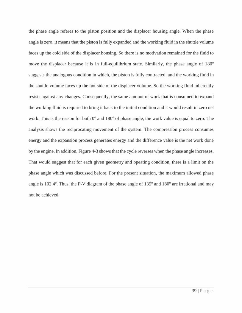
39 | P a g e
the phase angle referes to the piston position and the displacer housing angle. When the phase
angle is zero, it means that the piston is fully expanded and the working fluid in the shuttle volume
faces up the cold side of the displacer housing. So there is no motivation remained for the fluid to
move the displacer because it is in full-equilibrium state. Similarly, the phase angle of 180o
suggests the analogous condition in which, the piston is fully contracted and the working fluid in
the shuttle volume faces up the hot side of the displacer volume. So the working fluid inherently
resists against any changes. Consequently, the same amount of work that is consumed to expand
the working fluid is required to bring it back to the initial condition and it would result in zero net
work. This is the reason for both 0o and 180o of phase angle, the work value is equal to zero. The
analysis shows the reciprocating movement of the system. The compression process consumes
energy and the expansion process generates energy and the difference value is the net work done
by the engine. In addition, Figure 4-3 shows that the cycle reverses when the phase angle increases.
That would suggest that for each given geometry and opeating condition, there is a limit on the
phase angle which was discussed before. For the present situation, the maximum allowed phase
angle is 102.4o. Thus, the P-V diagram of the phase angle of 135o and 180o are irrational and may
not be achieved.

40 | P a g e
Figure 4-3. Pressure vs Volume at different phase angles when Tc = 373 K and Th = 923 K.
The P-V diagrams are shown in Figure 4-4 for all conditions in Table 3. As the hot side
temperature increases, the temperature ratio ( ) decreases and causes increment in efficiency.
Figure 4-4. Comparison between P-V diagrams of the prototype for different hot side temperatures at a constant cold side temperature (373 K) and phase angle of 90o.

41 | P a g e
A beneficial diagram that could help out to see the effect of the phase angle is the work
ratio variations versus phase angle at a certain condition. If the phase angle of 90o is set as the
reference point, all other values can be compared with. Figure 4-5 shows the work value ratio at
different temperature ratios which exactly matches each other. It indicates that the work ratio is
independent of temperature values and behaves the same. As it was shown before, the amount of
work at the phase angle of zero and 180o is zero, so the value is equal to zero and it reaches the
maximum amount at the angle of 90o which would be one.
Figure 4-5. Generated work comparison with the phase angle at different values of temperature ratio and cold side temperature of 323 K.
The generated net work per cycle versus temperature ratio ( ) at different values
of cold side temperatures is s in Figure 4-6.a. Clearly, when the ratio is equal to one, the generated
work would be equal to zero. Also, it indicates that the less temperature ratio would create more
work. In other words, the amount of work increases when the temperature difference increases and

42 | P a g e
simuntinously, if the cold side temperature increases, the generated work would increase
Figure 4-6.b indicates that the amount of work changes linearly with respect to temperature ratio
at a constant hot side temperature.
Figure 4-6. Generated work vs. temperature ratio at different cold side and hot side temperatures at the phase angle of 90o
a) Work vs τ at different values of
b) Work vs at different values of

43 | P a g e
One of the most significant variables that must be studied and taken seriously is the amount
of “dead volumes” that could have enormous effect on the engine performance. Dead volumes
decribe the volume of connecting pipes or inevitable space that must be added to the engine to
complete the design, otherwise the engine would not operate. They add nothing but disadvantages.
When the working fluid passes through the dead volumes, the very immediate effect would be
pressure loss. In addition, joints that connect them to the engine parts could have leakage. The
maximum performance is gained when the dead volume does not exist but this would be practically
impossible to have. Thus, the best manner is to minimize the damage. If the ideal situation is
assumed as having no dead volumes ( , other amount of dead volumes can be
compared with it. Figure 4-7 shows the generated work ratio over the generated work when the
dead volume is zero versus shuttled volume at different dead volume ratios. As the shuttled volume
increaces, the effect of the dead volume is diminished. However it is not feasible to increase the
displacer housing size unlimited but instead, by having a closer look at the figure, it is noticed that
for each value of dead volume, the diagram starts with a remarkable slope and then the slope is
decreased gradually. Therefore, for each induced value of dead volume, with an engineering
perspective, roughly 85 percent of the ideal condition work should be obtained. For instance, if
is equal to 0.4, then the affordable comensurate value of would be nearly 5.

44 | P a g e
Figure 4-7. Work ratio vs shuttled volume ratio at different dead volume ratios at and.
4.2 Non-Ideal Analytical Model In order to analyze the results, the existing prototype is chosen to be studied with working
fluid “Helium”. The engine configuration is shown in Table 4-4. McCarty showed that the specific
heat capacities of Helium do not change with temperature at the range of 65o K and 1500o K [27].
Table 4-4. The specifications of the engine prototype.Specification Value Thermal Resistance of the displacer housing body (W.m-1K-1) 16.3
Connecting pipes diameter (m) 6.35×10⁻³
Hot side connecting pipe 1 length (m) 6.51×10⁻²
Hot side connecting pipe 2 length (m) 1.19×10⁻¹
Cold side connecting pipe 1 length (m) 2.55×10⁻²
Cold side connecting pipe 2 length (m) 5.09×10⁻²
Displacer housing outer radius (m) 4.45×10⁻²
Displacer housing inner radius (m) 2.87×10⁻²
Displacer housing outer area (m2) 1.38×10⁻²
Displacer housing inner area (m2) 3.17×10⁻⁵

45 | P a g e
The Helium specific heat capacity at constant pressure, is 5119 J.kg-1.K-1 and the specific heat capacity at constant volume,
is 3116 J.kg-1.K-1. The amount of working fluid is computed like the ideal model; it is assumed that the engine is pressurized under
the room temperature condition. So the amount of mass is 1.9655×10⁻⁵ kg. The model is resolved for different hot side temperatures
(TH) when the cold side temperature (TC) is 373 K. The amount of source and sink heat is calculated from the ideal model. Table 4-5
shows the assumed temperature ratios and frequencies and also the amount of heat source and heat sink and temperature values inside
the displacer housing.
Table 4-5. Computed inner temperatures of displacer housing at .
0.4 0.5 0.6 0.7 0.8 0.9 1 932.5 746.0 621.7 532.9 466.3 414.4 373.0
20 374.9 929.2 374.8 743.3 374.7 619.3 374.7 530.8 374.6 464.4 374.6 412.8 374.5 374.5 30 375.9 927.5 375.7 741.9 375.6 618.2 375.5 529.8 375.4 463.5 375.3 411.9 375.3 375.3 40 376.8 925.8 376.6 740.5 376.4 617.0 376.3 528.7 376.2 462.6 376.1 411.1 376.1 376.1 50 377.8 924.2 377.5 739.1 377.3 615.8 377.1 527.7 377.0 461.7 376.9 410.3 376.8 376.8 60 378.7 922.5 378.4 737.8 378.1 614.6 378.0 526.7 377.8 460.7 377.7 409.4 377.6 377.6

46 | P a g e
The Reynolds variations in connecting ports are shown in Figure 4-8. As the figure indicates,
there is a direct relation between the value of Reynolds and frequency. In other words, as it is
increased, the Reynolds is also increased. In addition, the figure shows that there is a laminar flow
traveling inside the port. According to the definition of laminar flow, when , the flow
friction factor is defined by eq. (43) [25]:
(43)
Figure 4-8. Reynolds variation vs. frequency in the connecting ports.
Therefore, the amount of pressure drop can be computed from eq. (42). Figure 4-9 shows the
amount pressure drop at different frequencies. The diagram suggests that value of pressure drop
decline by increment in the temperature ratio and frequency. However, all values are so small
which can be even neglected.

47 | P a g e
Figure 4-9. Pressure drop over the mean pressure vs. temperature ratio at different frequencies.
Figure 4-10 shows the output power versus different temperature ratios at different
temperature. As it is expected, the generated power is equal to zero when the temperature ratio is
equal to 1 because the system is at equilibrium state. The output power increases when the
temperature ratio declines. By increasing frequency, the amount of generated power increases
because there is a direct relation between the output power and frequency. Thus by having the
same amount of temperature ratio, the output power increases. At this stage, it was decided to stop
measuring the values of other pressure drops but it is believed there would be more which would
have to be studied.
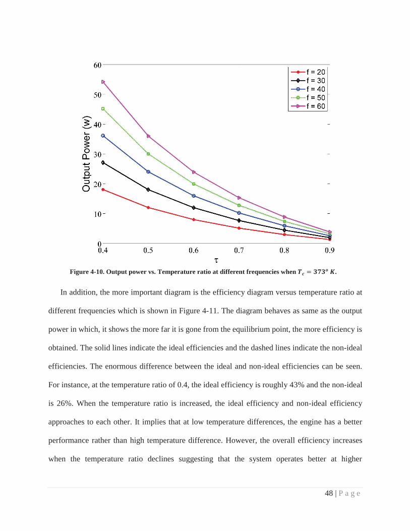
48 | P a g e
Figure 4-10. Output power vs. Temperature ratio at different frequencies when .
In addition, the more important diagram is the efficiency diagram versus temperature ratio at
different frequencies which is shown in Figure 4-11. The diagram behaves as same as the output
power in which, it shows the more far it is gone from the equilibrium point, the more efficiency is
obtained. The solid lines indicate the ideal efficiencies and the dashed lines indicate the non-ideal
efficiencies. The enormous difference between the ideal and non-ideal efficiencies can be seen.
For instance, at the temperature ratio of 0.4, the ideal efficiency is roughly 43% and the non-ideal
is 26%. When the temperature ratio is increased, the ideal efficiency and non-ideal efficiency
approaches to each other. It implies that at low temperature differences, the engine has a better
performance rather than high temperature difference. However, the overall efficiency increases
when the temperature ratio declines suggesting that the system operates better at higher

49 | P a g e
temperature differences. Moreover, the diagram indicates that the efficiency is independent from
frequency and may vary only by changing the temperature ratio.
Figure 4-11. Mechanical efficiency vs. Temperature ratio at different frequencies when .

50 | P a g e
5 CONCLUSIONS
The main conclusions and observations for this project and also recommendations for future
works are presented in this chapter.
5.1 Remarks
In the ideal approach, a rotary displacer Stirling engine is analyzed with the assumptions
adopted from the Schmidt analysis, in order to identify significant variables. Although the analysis
considers ideal conditions, it could successfully depict the harmonic motion of the new
configuration and illustrated the effect of two important variables; the amount of dead volume and
the maximum phase angle. In summary, the following conclusions can be drawn:
The maximum ideal phase angle is computed with a new approach based on the
temperature ratios and the geometry.
The phase angle is utterly independent from the temperature ratio and in the ideal
condition, the maximum work would be obtained when the phase angle is 90o.
Considering a constant temperature ratio, the higher sink (cold side) or source (hot side)
temperatures would result in greater amount of work.
The effect of dead volume in engine performance is discussed. It is shown that at a given
dead volume ratio, work ratio increases as shuttled volume ratio increases. Also, at higher
shuttled volume ratios (>5) the negative effect of dead volume rapidly diminishes.
In the non-ideal approach, as the effect of pressure drop and temperature loss were considered,
it was shown that the realistic model could have a vast difference with the ideal one. The results
are summarized as following:

51 | P a g e
The power piston is inherently not in touch with the body, therefore it was assumed that
there was no friction during the piston movement.
The effect of pressure drop through the connecting pipes was negligible since the flow
regime was laminar.
The conduction loss resulted a drastic effect on the overall performance which even
reached a 25% difference in efficiency.
It was shown as it had been expected, the generated power would increase when the
temperature ratio declines and the efficiency is close to the ideal case when it approaches
to zero.
5.2 Recommendations for Future Work
There are some lacks in this study that the author is interested to be completed.
1- It is recommended to study the engine performance experimentally and compare the non-
ideal model with the realistic data in order to ensure that the model would match up with
minor errors.
2- Another research could be done over the displacer housing in order to figure out the amount
of heat transfer coefficient (h) that would provide researches a very precise estimation over
the flow regime inside the housing.
3- A computational fluid dynamics work is also recommended in order to comprehend the
flow behavior inside the displacer housing and study the housing geometric variables
(including length, diameter and fins existence).

52 | P a g e
REFERENCES
1. Foster, P.R., Liquid cooled stirling engine with a segmented rotary displacer. 2013,Google Patents.
2. Schmidt, G., The theory of lehmans calorimetric machine. Z Vereines DeutcherIngenieure, 1871: p. 15.
3. Sonntag, R.E., et al., Fundamentals of thermodynamics. Vol. 6. 1998: Wiley New York.
4. Sonntag, R.E. and G.J. Van Wylen, Introduction to thermodynamics. 1991: Wiley.
5. Foster, P.R., Innovative Rotary Displacer Stirling Engine: Sustainable Power Generationfor Private and Fleet Vehicle Applications. 2011.
6. Walker, G., Stirling engines. 1980.
7. Organ, A.J., Thermodynamics and gas dynamics of the Stirling cycle machine. 1992:Cambridge University Press.
8. Urieli, I. and D.M. Berchowitz, Stirling cycle engine analysis. 1984: Taylor & Francis.
9. Beale, W. and D.M. Berchowitz, Understanding Stirling engines. 1984: Volunteers inTechnical Assistance.
10. West, C. Theoretical basis for the Beale number. in Proc., Intersoc. Energy Convers.Eng. Conf.;(United States). 1981. Westware Co, Oliver Springs, Tenn, USA.
11. Senft, J. A simple derivation of the generalized Beale number. in IECEC'82; Proceedingsof the Seventeenth Intersociety Energy Conversion Engineering Conference. 1982.
12. Iwamoto, S., K. Hirata, and F. Toda, Performance of Stirling Engines. Arranging Methodof Experimental Results and Performance Prediction. JSME International Journal SeriesB, 2001. 44(1): p. 140-147.
13. Prieto, J., et al., Preliminary design of the kinematic Stirling engine using dynamicsimilarity and quasi-static simulation. Proceedings of the Institution of MechanicalEngineers, Part C: Journal of Mechanical Engineering Science, 1997. 211(3): p. 229-238.
14. Kolin, I., Stirling motor: history, theory, practice. 1991: Inter University Center.

53 | P a g e
15. Organ, A.J., The regenerator and the Stirling engine. 1997: wiley.
16. Kongtragool, B. and S. Wongwises, Investigation on power output of the gamma-configuration low temperature differential Stirling engines. Renewable Energy, 2005.30(3): p. 465-476.
17. Senft, J.R., Mechanical efficiency of heat engines. 2007: Cambridge University Press.
18. Lloyd, C.C., A Low Temperature Differential Stirling Engine for Power Generation.2009.
19. Parlak, N., et al., Thermodynamic analysis of a gamma type Stirling engine in non-idealadiabatic conditions. Renewable Energy, 2009. 34(1): p. 266-273.
20. Formosa, F. and G. Despesse, Analytical model for Stirling cycle machine design. EnergyConversion and Management, 2010. 51(10): p. 1855-1863.
21. Kwankaomeng, S., B. Silpsakoolsook, and P. Savangvong, Investigation on Stability andPerformance of a Free-piston Stirling Engine. Energy Procedia, 2014. 52: p. 598-609.
22. Hoegel, B., Thermodynamics-based design of stirling engines for low-temperature heatsources. 2014.
23. Incropera, F. and D. DeWitt, Introduction to heat transfer. 1985.
24. Mobley, R.K., Fluid power dynamics. 1999: Butterworth-Heinemann.
25. White, F.M. and I. Corfield, Viscous fluid flow. Vol. 3. 2006: McGraw-Hill New York.
26. Sala, F. and C.M. Invernizzi, Low temperature Stirling engines pressurised with real gaseffects. Energy, 2014. 75: p. 225-236.
27. Mc Carty, R.D., Thermodynamic Properties of Helium 4 from 2 to 1500 K at Pressures to108 Pa. Journal of Physical and Chemical Reference Data, 1973. 2(4): p. 923-1042.