massachusetts institute of technology department of...
TRANSCRIPT

Massachusetts Institute of TechnologyDepartment of Electrical Engineering and Computer Science
Proposal for Thesis Research in Partial Fulfillmentof the Requirements for the Degree of
Doctor of Philosophy
Title: Manipulating Machines: Designing Robots to Grasp Our World
Submitted by: Aaron EdsingerMIT CSAIL (Signature of Author)
32 Vassar Street, 32-380Cambridge, MA 02139
Date of submission: January 9, 2005
Expected Date of Completion: June 2006
Laboratory: Computer Science and Artificial Intelligence Lab (CSAIL)
Brief Statement of the Problem:
Manipulation requires anticipatory actions. We preshape our grasp before making contact withan object and stiffen our arm in anticipation of lifting a heavy one. These actions preconditionthe manipulation engagement to minimize the effects of short timescale dynamics. The goal ofthe research proposed here is to contribute an approach to robot manipulation encompassing threeprincipal components: force sensing and compliant manipulation in unstructured environments, adecentralized, behavior based cognitive architecture, and the integration of anticipatory sensorimotorcues into the robot’s behavioral repertoire. A control architecture, pARC, is proposed as a frameworkfor incorporating anticipatory information into a behavior based decomposition. The approach willbe demonstrated through a series of manipulation scenarios conducted on a new 29 degree-of-freedomforce controlled humanoid robot named Domo.
1
Contents
1 Introduction 4
1.1 Research Components . . . . . . . . . . . . . . . . . . . . . . . . . . . . . . . . . . . 5
1.2 Work Milestones . . . . . . . . . . . . . . . . . . . . . . . . . . . . . . . . . . . . . . 6
1.3 Roadmap . . . . . . . . . . . . . . . . . . . . . . . . . . . . . . . . . . . . . . . . . . 6
2 Compliant and Force Sensitive Manipulators 7
2.1 Force Sensing Compliant and Series Elastic Actuators . . . . . . . . . . . . . . . . . 7
2.2 Virtual Model Control . . . . . . . . . . . . . . . . . . . . . . . . . . . . . . . . . . . 9
3 Behavior Based Decomposition 10
3.1 Building Artificial Creatures . . . . . . . . . . . . . . . . . . . . . . . . . . . . . . . . 11
3.2 Review: Behavior Based Manipulation . . . . . . . . . . . . . . . . . . . . . . . . . . 11
3.3 The Components of Dexterous Manipulation . . . . . . . . . . . . . . . . . . . . . . 13
4 Implicit Predictive Models 13
4.1 Efference Copy . . . . . . . . . . . . . . . . . . . . . . . . . . . . . . . . . . . . . . . 14
4.2 Mataric’s Navigation and Landmarks . . . . . . . . . . . . . . . . . . . . . . . . . . . 15
4.3 The pARC Framework . . . . . . . . . . . . . . . . . . . . . . . . . . . . . . . . . . . 16
4.3.1 pARC Terminology . . . . . . . . . . . . . . . . . . . . . . . . . . . . . . . . 16
4.3.2 Predictive and Behavior Layers . . . . . . . . . . . . . . . . . . . . . . . . . . 17
4.3.3 Signals, Wires, and Gates . . . . . . . . . . . . . . . . . . . . . . . . . . . . . 18
4.3.4 Predictive and Behavior Kernels . . . . . . . . . . . . . . . . . . . . . . . . . 20
4.3.5 pARC Example: Reaching to a Target . . . . . . . . . . . . . . . . . . . . . . 21
4.3.6 pARC Detailed Example: Hand Localization . . . . . . . . . . . . . . . . . . 23
5 Manipulation Scenarios 24
5.1 Developing a Body Schema . . . . . . . . . . . . . . . . . . . . . . . . . . . . . . . . 25
5.2 Playing Tether Ball . . . . . . . . . . . . . . . . . . . . . . . . . . . . . . . . . . . . . 27
5.3 Playing Karate Sticks . . . . . . . . . . . . . . . . . . . . . . . . . . . . . . . . . . . 29
5.4 Putting Away Toys . . . . . . . . . . . . . . . . . . . . . . . . . . . . . . . . . . . . . 30
6 Milestones and Timeline 31
1

A The Robot Platform 37
A.1 Head . . . . . . . . . . . . . . . . . . . . . . . . . . . . . . . . . . . . . . . . . . . . . 37
A.2 Arms . . . . . . . . . . . . . . . . . . . . . . . . . . . . . . . . . . . . . . . . . . . . . 38
A.3 Hands . . . . . . . . . . . . . . . . . . . . . . . . . . . . . . . . . . . . . . . . . . . . 39
A.4 The Sensorimotor System . . . . . . . . . . . . . . . . . . . . . . . . . . . . . . . . . 40
A.4.1 Physical Layer . . . . . . . . . . . . . . . . . . . . . . . . . . . . . . . . . . . 41
A.4.2 DSP Layer . . . . . . . . . . . . . . . . . . . . . . . . . . . . . . . . . . . . . 41
A.4.3 Sensorimotor Abstraction Layer . . . . . . . . . . . . . . . . . . . . . . . . . . 42
2

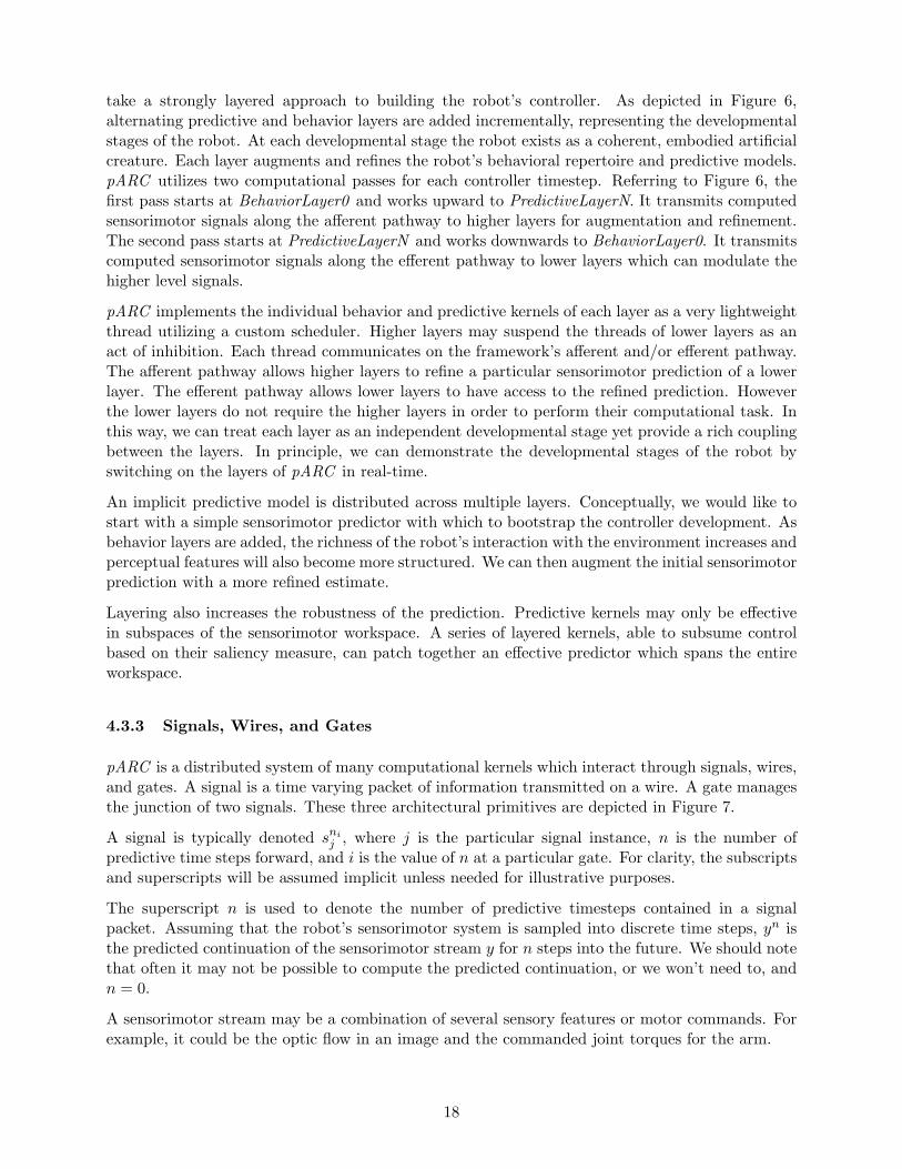
Figure 1: The manipulation platform Domo being developed for this work has 29 active degreesof freedom (DOF), 58 proprioceptive sensors, and 24 tactile sensors. Of these, 22 DOF use forcecontrolled and compliant actuators. There are two six DOF force controlled arms, two four DOFforce controlled hands, a two DOF force controlled neck, and a seven DOF active vision head.The real-time sensorimotor system is managed by an embedded network of five DSP controllers.The vision system includes two FireWire CCD cameras. The cognitive system runs on a small,networked cluster of PCs.
Abstract
Manipulation requires anticipatory actions. We preshape our grasp before making contact withan object and stiffen our arm in anticipation of lifting a heavy one. These actions preconditionthe manipulation engagement to minimize the effects of short timescale dynamics. The goal ofthe research proposed here is to contribute an approach to robot manipulation encompassing threeprincipal components: force sensing and compliant manipulation in unstructured environments, adecentralized, behavior based cognitive architecture, and the integration of anticipatory sensorimotorcues into the robot’s behavioral repertoire. A control architecture, pARC, is proposed as a frameworkfor incorporating anticipatory information into a behavior based decomposition. The approach willbe demonstrated through a series of manipulation scenarios conducted on a new 29 degree-of-freedomforce controlled humanoid robot named Domo.

1 Introduction
Today’s robots are not able to manipulate objects with the skill of even a small child. For robotsto gain general utility in areas such as space exploration, small-parts assembly, agriculture, andeven in our homes, they must be able to intelligently manipulate unknown objects in unstructuredenvironments. Even a dog can turn a bone about with two clumsy paws in order to gain a betterapproach for gnawing. The Osprey, or fish hawk, has a 5 DOF foot which it uses to capture preywith remarkable dexterity [49]. These animals exhibit manipulation abilities not yet attained byrobots.
Recent successes have been seen with robots that can navigate unstructured environments. Theserobots, such as the Mars Sojourner [24], use a behavior based architecture to accommodate adynamic and unknown environment. However, these architectures haven’t been as succesful inmanipulation. We maintain that navigation and manipulation are fundamentally different in thetimescales involved. By example, consider the classic inverted pendulum experiment of balancinga stick on the tip of your finger. A purely reactive controller would sense the current angle ofthe stick and move the finger in the appropriate direction. This controller works for a long stickwhere the timescale of the pendulum dynamics is long compared to the timescale of the physicaldynamics of the motor system. As the stick gets shorter, the pendulum timescale becomes shorterand the reactive controller will fail. If the controller can anticipate the future sensorimotor stateof the system in a feedforward term, it can remain stable for shorter and shorter timescales.
Manipulation is not simply a matter of building stable controllers, but the physical dynamics in-volved require anticipatory actions where navigation often can take a purely reactive approach.Correcting a grasp to prevent dropping an object requires tens of millisecond timescale adjust-ments, navigating down a cluttered corridor requires adjustments on the timescale of hundredsof milliseconds and seconds. Given ample computation, a sense-compute-act control loop couldalways be made fast enough to accomodate shorter timescales. However, if the physical dynamicsof the motor system are fundamentally of a longer timescale than the robot-environment dynamics,anticipatory actions are required. Anticipatory actions advantageously bias the robot-environmentdynamics in advance. They provide robustness to disturbances to an on-going behavior throughfeedforward control. They predict the when and where of future sensorimotor cues based on his-torical sensorimotor experiences. We preshape our grasp before making contact with an object andstiffen our arm in anticipation of lifting a heavy one. These actions precondition the manipulationengagement to minimize the effects of short timescale dynamics. For example, a correct grasppreshape lessens our dependence on minute grasp adjustments.
The goal of the proposed research is to contribute a novel approach to robot manipulation inunstructured environments. The approach is centered on integrating compliant and force sensitivemanipulators into a behavior based architecture that supports anticipatory sensorimotor models.
A new 29 degree-of-freedom (DOF) upper-torso humanoid robot named Domo has been developedin order to investigate this approach. Domo is pictured in Figure 1. The robot exhibits differentphysical characteristics than typically found in manipulators. Traditional manipulators exhibit highstiffness and often use force-sensing load cells at the wrist and shoulder to deduce the forces actingon the arm. These manipulators can precisely control the position of each actuator but cannotdirectly control the force output. Domo exhibits reasonably high compliance in its joints andhigh fidelity force control at each joint. Its manipulator characteristics are analogous to humanmanipulators which are very good at controlling forces, but relatively poor at controlling jointposition [20].
4

Domo is not designed to emulate the dexterity and sensing of humans. The robot’s hands eachhave only 4 DOF, 12 tactile sensors, and are limited compared to a human hand. Traditionalcontrol methods used in manipulation are not well suited to the platform. Well defined modelsof objects have little value when using a manipulator without precise position control. However,the robot hardware developed does allow investigation of fundametal research issues surroundingmanipulation. Namely, how to integrate visual perception, manipulator forces, and anticipatorybehaviors in a tightly coupled interaction with the world.
We contend that the manipulation efficacy exhibited by a dog is not necessarily the result of findingoptimal relations between a model of its paw (which has little dexterity) and a model of the bone(which is poorly approximated by a generic model). We view the dog as engaged in a tightly coupledinteraction with the bone where it is modulating many different force based behaviors based on astream of visual, tactile, and olfactory information. The dog’s internal model of this interaction,if it is even correct to use the term ‘model’, is of predicted sensory consequences of the behaviors.Pushing the paw down on the bone with greater force results in less visual motion of the bone (dueto increased friction between the bone and the ground). A hypothetical robotic dog doesn’t needto construct a model of the bone, the paw, the ground, and the frictional forces. Instead it simplymust know to increase the paw force when the optic flow of the bone is too large.
Clearly there are circumstances where it is preferable to take a traditional model based approach,and the proposed approach to manipulation will likely be imprecise and coarse at first. However,it should be demonstrably better in circumstances where traditional approaches fall short, such asin real world, dynamic and unstructured environments.
1.1 Research Components
The proposed approach to robot manipulation has three principal research components:
1. Compliant and Force Sensing Manipulators: Robots working in unstructured envi-ronments depend on unreliable perceptual features to guide their manipulators. The motorsystem of the robot should be capable of directly controlling the forces it exerts on the world.This allows a force-based decomposition of manipulation tasks and it allows the robot tosafely move its manipulators when the precise location of objects in the environment arenot known. The motor system should also be reasonably compliant, providing robustness tounexpected collisions and passive adaptation to unknown object features.
2. Behavior Based Decomposition: Manipulation requires a tight coupling between theobject being manipulated, the robot sensory system, and the robot motor system. A behaviorbased decomposition divides the computational organization of a robot into an incrementalseries of layers. A layer exhibits externally observable coherent behavior. Successive layersare added incrementally and each results in improved or expanded coherent behaviors. Abehavior based decomposition applied to a force controlled manipulator provides a tight,reactive coupling between the manipulated object and the robot. It forgoes the need forexplicit models of the robot and the objects being manipulated. It also provides a systematicframework to integrate many low-level force sensitive behaviors in such a manner that higher-level, task oriented behaviors can be intuitively specified.
3. Implicit Predictive Models: The human motor system is characterized by large time de-lays. Consequently our cerebellum very likely functions as a predictive controller, anticipatingthe sensory consequences of movements before they occur and cancelling out self-generated
5

sensory stimuli [51]. A predictive model serves to anticipate sensory or motor consequencesof the current sensory and motor state. Such a model is constructed from a history of senso-rimotor experiences. An implicit predictive model fits into a behavior based decomposition.It lacks the explicit, centralized representation that is implied by the common use of the termmodel. Instead, the model is distributed across the layers of the behavior based framework.As behavior layers are incrementally added to the robot controller, the implicit predictivemodel is also expanded and improved upon. A common criticism of strictly reactive, behav-ior based architectures is that they lack state and the ability to exploit experience. Implicitpredictive models can serve as means to integrate state into a behavior based decomposition.These models can then be used to:
(a) adapt behaviors, as in the case of modulating arm stiffness.
(b) generate behaviors, as in the case of grasp preshaping.
(c) amplify salient sensory signals. For example, a predictive model of self-generated opticflow can be used to amplify the optic flow generated by the external world.
(d) reduce noise in sensory signals. For example, a visual object tracker will often lose atracked object for a few frames. Objects in the real world don’t suddenly disappear andthen reappear. A predictive model can be used to anticipate the continuation of theobject trajectory despite noise in the tracker.
1.2 Work Milestones
There are three primary milestones to our work:
1. Design and construction of the robot platform Domo. The design is centered on pro-viding a robust platform which can support rich, prolonged sensorimotor experiences duringmanipulation engagements.
2. Implementation of a set of primitive behaviors for the robot. These bootstrapthe system to engage in basic exploratory manipulation acts. This includes development offorce controllers for the manipulators, grasping postures for the hand, simple visual featuredetectors, and an attentional system to guide the robot towards salient stimuli.
3. Development of an anticipatory control architecture and its application to Domothrough a series of manipulation scenarios. The architecture is named pARC , shortfor Predictive Architecture. pARC serves as a tool to integrate new behaviors into the robotover time. Domo’s manipulation competency will be improved incrementally by expandingand refining the robot’s behaviors, predictive models, and visual percepts. At each develop-mental stage, the robot will exhibit coherent and integrated behaviors. The complexity ofthe manipulation scenarios conducted is also increased at each developmental stage.
1.3 Roadmap
In the remainder of this document we elaborate on our principal research components and workmilestones.
Section 2 describes the compliant and force sensing manipulators designed specifically for ourresearch approach and presents a control methodology for them. Section 3 reviews behavior based
6
approaches to manipulation and provides a behavior based decomposition to be used in this work.Section 4 expands the notion of implicit predictive models and formulates the pARC framework.A series of manipulation scenarios are described in Section 5. Section 6 outlines a timeline for theimplementation of the proposed work. The mechanical and software design of Domo is describedin Appendix A.
2 Compliant and Force Sensitive Manipulators
Humans are very good at controlling manipulator forces, but relatively poor at controlling jointposition, as demonstrated by Kawato’s [20] study of arm stiffness during multi-joint movements.Joint torque in the human arm is generated by an imbalance of tension between antagonist andagonist muscles which have inherently spring-like properties. Equilibrium-point control (EPC)[38]is an influential model for arm movement which posits that the spring-like viscoelastic propertiesof muscles provide mechanical stability for control. Joint posture and joint stiffness is maintainedby modulating the tension of the agonist/antagonist muscle pair. EPC provides a method of armcontrol which does not require computing a model of the complex dynamics of the arm.
EPC is only part of the story of human arm control. However the notion that spring and damperlike qualities in the manipulator can be exploited for stable and simplified control can be appliedto robot limb control as well.
Based on previous work done on the robots Cog [9] and Spring Flamingo [46], we have built robotarms and hands specifically designed to support physical and simulated spring-damper systems.Our supposition is that, in the context of manipulation, compliant and force sensing manipulatorscan significantly modify the shape of the problem space into one that is simpler and more intuitive.These manipulators allow a force-based decomposition of manipulation tasks, allow the robot tosafely move when the location of objects in the environment are not well known, and provide arobustness to unexpected collisions.
In this section we describe two related actuators, the Series Elastic Actuator[45] (SEA) and theForce Sensing Compliant Actuator (FSCA) [13]. We have developed the FSCA as an alternativeto the SEA when very compact force sensing is required. We also describe an existing method ofcontrolling these actuators called Virtual Model Control [26].
2.1 Force Sensing Compliant and Series Elastic Actuators
The 20 actuators in Domo’s arms and hands and the 2 actuators in the neck utilize series elasticityto provide force sensing. We place a spring inline with the motor at each joint. We can thenmeasure the deflection of this spring with a potentiometer and know the force output by usingHooke’s law (F = −kx where k is the spring constant and x is the spring displacement). We applythis idea to two actuator configurations, as shown in Figure 2. The SEA places the spring betweenthe motor and the load, while the FSCA places the spring between the motor housing and thechassis ground. There are several advantages to these actuators:
1. The spring and potentiometer provide a mechanically simple method of force sensing.
2. Force control stability is improved when intermittent contact with hard surfaces is made.This is an important attribute for manipulation in unknown environments.
7

Motor GearTrain
Series Elasticity
Load
Potentiometer
Series Elastic Actuator
Motor GearTrain
Series Elasticity
Load
Potentiometer
Force Sensing CompliantActuator
Figure 2: Block diagram of the Series Elastic Actuator and the Force Sensing Compliant Actuator.The SEA places an elastic spring element between the motor output and the load. The FSCA placesthe spring element between the motor housing and the chassis ground. SEAs are used in Domo’sarms and neck. FSCAs are used in Domo’s hands.
3. Shock tolerance is improved. The use of an N : 1 geartrain increases the reflected inertia at themotor output by N2. This results in shock loads creating high forces on the gear teeth. Theseries elastic component serves as a mechanical filter of the high bandwidth forces, reducingthe potential of damage to the gears.
4. The dynamic effects of the motor inertia and geartrain friction can be actively cancelledby closing a control loop around the sensed force. Consequently, we can create a highlybackdrivable actuator with low-grade components.
5. The actuators exhibit passive compliance at high frequencies. Traditional force controlledactuators exhibit a large impedance at high frequencies because the motor response is insuf-ficient to react at this timescale. In an SEA, the impedance of the elastic element dominatesat high frequencies.
The overall passive compliance exhibited by the SEA or FSCA is determined by the spring stiffness.If we consider that an external force applied to the actuator can only be counteracted by the spring,then we see that the mechanical impedance of the system is defined by that of the springs. Thelow impedance of the springs adversely affects the reaction speed, or bandwidth, of the system. Forrobot tasks achieved at a roughly human level bandwidth, this adverse effect is not large.
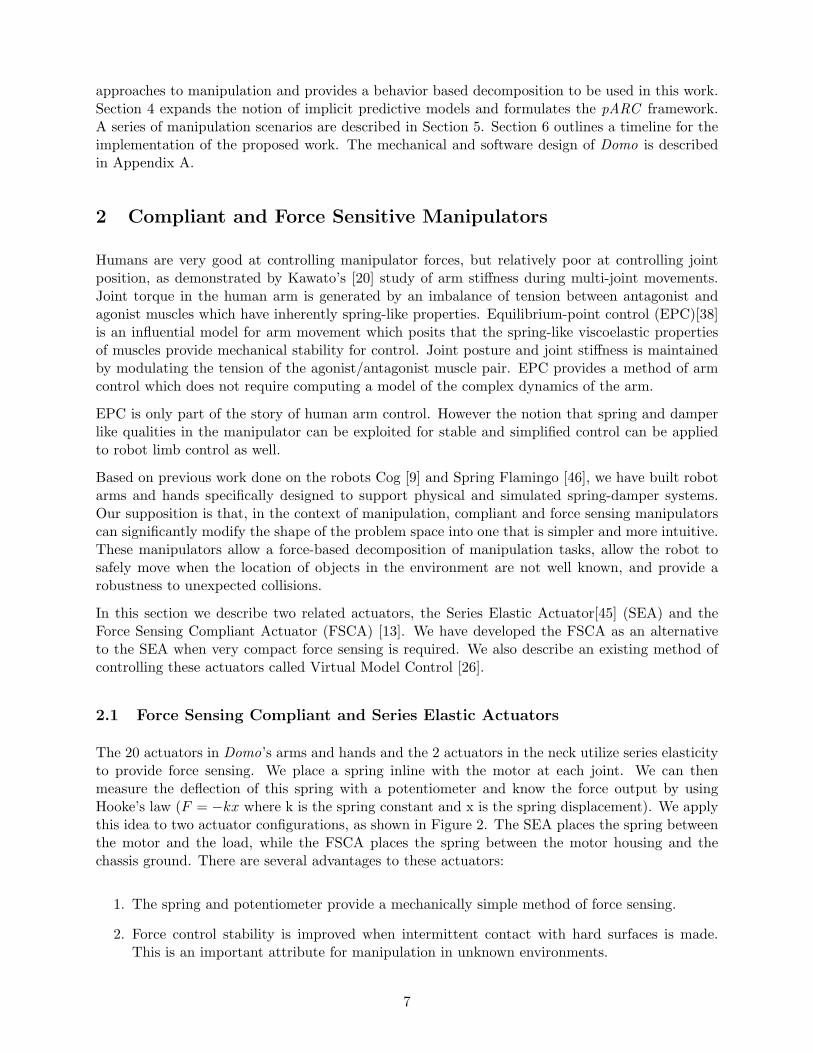
The differences between the FSCA and the SEA provide distinct advantages and disadvantages.The SEA, as pictured in Figure 3, uses a linear ballscrew and a cable transmission. The ballscrewprovides greater efficiency and shock tolerance than a gearhead. The SEA is limited by the travelrange of the ballscrew which creates packaging difficulties. The linear potentiometer must movewith the motor output, precluding the use of continuous rotation configurations. In contrast, theFSCA can allow continuous rotation at the motor output as the potentiometer does not move withthe motor. However, the elastic element is not between the load and the geartrain, decreasing theshock tolerance.
8
A
B
D
E
C
F
(1) SEA
H I
J
G
(2) FSCA
Figure 3: (1) Model of the cable-drive SEA. A brushless DC motor (A) imparts a linear motion tothe inner drive carriage (C) through a precision ballscrew (E). The inner drive carriage transmitsmotion to the outer drive carriage (F) through two precompressed die springs (D). The deflectionof the springs is measured with a linear potentiometer (B). (2) A simplified view of the FSCA.Two bearings (H) support the motor (G). The motor is attached to an external frame (ground)through two torsion springs (J). As the motor exerts a torque on a load, a deflection of the springsis created. This deflection is read by the torque sensing potentiometer (I).
2.2 Virtual Model Control
The force sensing actuators in Domo’s arms and hands will be controlled using Virtual ModelControl (VMC). VMC is an intuitive control methodology in the same category as EPC, as wellas operational space control, developed by Kahtib [30]. It was developed initially for biped robots[26] which exhibited very naturalistic walking gaits using SEAs.
VMC represents the control problem in terms of physical metaphors about which we have a goodnatural intuition: springs and dampers. Virtual springs and dampers are simulated between therobot’s links and between the robot and the external world. This allows force controlled movementof the manipulator with only a forward kinematic model. Dynamic models of the arm are notrequired.
The key idea of VMC is to add control in parallel with the natural dynamics of the arm. When welift a milk jug into the refrigerator, we exploit the pendulum dynamics of the system to give the juga heave. Traditional control methods override the natural dynamics of the manipulator. Instead,the manipulator follows a prescribed trajectory in joint space. A force sensing and compliant ma-nipulator, however, can allow the natural dynamics to be exploited. Its trajectory is the compositeof the natural dynamics interacting with a set of virtual springs and with the environment.
The robot Cog demonstrated exploitation of natural dynamics in a number of rhythmic tasks,including sawing, hammering, and playing with a Slinky [58]. With VMC, we add layers of springsand dampers in parallel with the natural dynamics. Figure 4 illustrates an example of applyingVMC to safely guide Domo’s arm to reach towards a target. In this illustration, virtual spring-
9
f 2
f 1
1
2
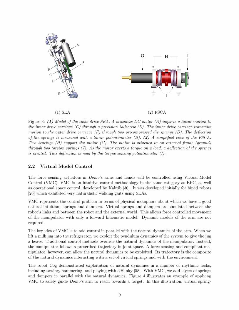
Figure 4: A simple illustration of Virtual Model Control of an arm. Virtual springs and dampers areattached between the robot body and the arm (~f2) and between the end effector and the reach target(~f1). With a forward kinematic model we can determine the arm jacobian, J . These instantaneousforces can be mapped to desired joint torques: ~τ = JT F
dampers are used of the form f = −ksx + kdx, where x is the spring displacement. Each spring-damper yields instantaneous forces on the arm, ~f1 and ~f2. The force ~f1 guides the arm towards atarget. The force ~f2 repels the elbow of the arm away from the body to avoid collisions. With aforward kinematic model we can determine the arm jacobian, J , which relates the velocity of theend-effector (or elbow) to the joint angular velocities. The end-effector force then relates to thejoint torque by ~τ = JT F [10].
The joint torques ~τ can be commanded to the SEA with a simple PID controller, simulating thevirtual springs. The stiffness of the arm can be controlled dynamically by modifying ks, and sets ofsprings can be add incrementally, and in parallel, to the natural dynamics of the arm. Additionally,non-linear springs may be simulated to create specific spring behaviors.
3 Behavior Based Decomposition
Behavior based control architectures have proven very successful for navigating mobile robots innon-laboratory environments. Architectures of this class have been used on the Mars Sojourner[24], the Packbot robot deployed for military operations, and in the Roomba household vacuumcleaner. The control architecture in these robots decomposes the navigation problem into a set ofinteracting, layered behaviors.
We maintain that today, much of robot manipulation in unstructured environments is similar towhere robot navigation was 20 years ago. For example, the Stanford Cart [42] built detailedmodels and plans at every step during navigation. It moved one meter every ten to fifteen minutes,in lurches, and movement of natural shadows during this time would create inaccuracies in itsinternal model.
Similarly, much of the current work in robot manipulation uses quasistatic analysis, where detailedstatic models are used to compute grasp stability, for example, at each time step. This is a classic
10

look-think-act decomposition where the robot senses the environment, builds a detailed model ofthe world, computes the optimal action to take, and then executes the action.
Real world manipulation tasks involve unstructured and dynamic environments. In this setting,explicit models and plans are unreliable. A look-think-act approach to manipulation, at least at thelower levels of control, renders the robot unresponsive. For example, in the time it takes a robot tobuild a model and compute an action, a slipping object will likely have dropped from the robot’sgrasp. Manipulation is characterized by a high-bandwidth coupling between the manipulator forcesand the object. A behavior based decomposition provides this coupling.
3.1 Building Artificial Creatures
A behavior based decomposition allows us to incrementally build the robot as an artificial creature.We use the term creature to suggest that a robot should, in principle, be left switched on to interactwith the environment for extended periods of time. It should exhibit a coherent set of behaviorswhich are appropriately responsive to its environment. The robot should exist in the world as a(nearly) always-on entity, analogous to a living creature. The name is not, however, meant to implythe robot’s relationship with biologically inspired models of robot design.
Currently, most humanoids are left to run only for the duration of an experiment. Our approachwith Domo is to bootstrap the robot with a primitive set of exploratory behaviors that will generatestructured sensorimotor patterns of activity. These sensorimotor patterns can then be used tobuild additional behaviors. At each point in the incremental construction of the robot controller,we impose the artificial creature constraint. This constraint, borrowing from Brooks [6], stipulatesthat the robot should exhibit:
1. Coherence: The interaction of many behaviors should appear outwardly coherent. Thisrequires the appropriate switching of behaviors in response to a changing environment.
2. Salience: The robot should be responsive to salient perceptual stimuli. Saliency can bemodulated by an attention system driven by a set of drives, as demonstrated with the robotKismet [5].
3. Adequacy: The robot should generate behavior which achieves a set of prescribed goals.For Domo, these may be exploring its workspace, or grasping certain types of objects. Thesegoals can be incrementally expanded over times.
The artificial creature constraint requires developing a method for integrating competing behaviors.The behavior selection problem is well studied and a variety of methods are available [5, 48]. Theconstraint also requires imparting the robot with a set of drives and a motivational system to attendto salient stimuli. We propose a system similar to those previously developed in our lab with Cogand Kismet.
3.2 Review: Behavior Based Manipulation
There is a wealth of literature on traditional approaches to manipulation. For an overview, see [35].Work on behavior based decompositions of manipulation has been scarce, especially on real worldhumanoid robots. Unfortunately, this work is typically characterized by incomplete integrationof the perceptual systems and motor behaviors. The complexity of the systems, or perhaps just
11

the nature of research, hasn’t allowed the humanoid platforms to be built as integrated, artificialcreatures as described above. Here we review related work where a behavior based decompositionhas been employed at least in part.
Some of the earliest work in behavior based manipulation was conducted by Brooks et al. withthe robot Cog [9]. Cog, like our robot Domo, had two force controllable arms utilizing SEAs. Ithad a 7 DOF active vision head and a rudimentary force controlled gripper. The predominantwork on the platform focused on active visual perception [15], multi-modal integration [2], andhuman imitation [50]. Williamson developed a set of rhythmic behaviors with the arms usingneural oscillators [58]. However, the electromechanical robustness of the manipulators ultimatelylimited their utility in exploring the manipulation problem space. All of these systems were neverintegrated into a coherent framework.
Marjanovic [34] proposed the only truly integrative architecture for Cog. The proposed frameworkallows behavioral competencies to be embedded in a distributed network. The framework supportsthe incremental layering of new abilities and the ability to learn new behaviors by interactingwith itself and the world. The learning is accomplished by autonomous generation of sensorimotormodels of the robot’s interaction with the world. Unfortunately, the system proved perhaps toogeneral and only simple behaviors were learned in practice. Manipulation problems were neverdirectly addressed. However, the framework does provide an example of an integrative approachto building behavior based robots.
One of the most thorough explorations of behavior based manipulation thus far has been achievedby Grupen et al. [44], in which an outline for a hierarchical framework for humanoid robot controlis proposed. Their work is tested on a real humanoid platform, Dexter, which features 2 forcesensing Whole Arm Manipulators (WAMS) with 7 DOF each, an active vision head, and 2 forcesensing hands with 4 DOF each.
The Dexter project decomposes the robot controller into a set of control basis behaviors, eachof which is a low-dimensional sensorimotor feedback controller. These behaviors are combined byprojecting the control basis of one controller onto the nullspace of the other. Novel controllers can belearned with reinforcement learning techniques. For example, a grasping policy was learned whichswitches between two and three fingered grasps based on the state of the grasping interaction. Theyhave also conducted work in incremental development of grasp controllers which do not require ana priori object model [21] and in learning haptic categories which can be used to associated visualand haptic cues with appropriate grasps [27].
The Sandini Lab has taken a developmental approach to humanoid robot manipulation, primarilywith the robot Babybot [39, 43]. This robot has a single PUMA arm with coarse force control, a 16DOF hand with only six actuators and passive compliance, and a 5 DOF active vision head. Theirapproach draws heavily on infant development and developmental psychology. Their approachutilizes development stages and non-model based control which fits into our notion of a behaviorbased manipulation system. Natale [43] proposes an actor-critic learning scheme for function ap-proximation of sensorimotor activity during exploratory motions. This scheme utilizes a layeredset of actor-critic modules which interact in a traditional behavior based architecture. They havealso investigated tightly coupled visual and motor behaviors to learn about object affordances [14].Knowledge about the object affordances is then exploited to drive goal-directed behavior.
12

3.3 The Components of Dexterous Manipulation
We propose that manipulation consists of nine different components [7]. These components can beconcurrent, can occur multiple times during the manipulation engagement, and provide a high-levelbehavior based decomposition. Briefly, these components are:
1. Deciding on actions. A sequence of actions is determined based on the task at hand. Inwell characterized settings this sequence may be determined ahead of time; otherwise, it isgenerated by perceptually guided action selection mechanisms.
2. Positioning sensors. Sensors, such as a camera, need to be positioned to get appropri-ate “views” of the elements of the engagement. Positioning should occur as a result of adynamically coupled loop between the sensor and the environment.
3. Perception. Perception continues throughout the engagement. Primarily the robot needs agood understanding of where things are and what objects with what properties are presentbefore moving a manipulator in to engage.
4. Placing body. The pose of the robot body is adapted to allow an advantageous reach ofthe workspace and the ability to apply the required forces during the engagement.
5. Grasping. A generic dexterous hand must form a stable grip that is appropriate for anyfuture force or transfer operations that are to be done with the object. This requires coordi-nating the many degrees of freedom in the hand and arm with visual and tactile perceptualstreams.
6. Force operations. The central component of dexterous manipulation is the modulation ofthe interaction forces which occur between the manipulator and the object. The manipulatormust apply appropriate forces and modify those forces in real time based on the response ofthe objects or material being manipulated.
7. Transfer. The manipulator transfers the object to a desired location, avoiding obstacles asnecessary. This requires local knowledge of the environment.
8. Disengaging. The object is released from the grasp in the correct location and pose. Thiscan be considered the inverse of grasping.
9. Detecting failures. The robot should detect when action has failed. This is a perceptualproblem but requires feedback into the action selection process.
4 Implicit Predictive Models
Anticipatory actions can be generated with implicit predictive models. An implicit predictive modelis a model of the robot’s sensorimotor relationships based on prior historical experience. Implicitdenotes that the model is distributed across the system. There is not a global model of the robotsensorimotor system and the environment. Predictive denotes possible use as forward model, wherethe future sensorimotor state is anticipated prior to occurrence.
Implicit predictive models are motivated by findings in neuroscience that the brain very likely usesdistributed forward and inverse sensorimotor models to anticipate sensory consequences of motoractions. These models, commonly referred to as efference copy mechanisms, are reviewed below.
13

Z n
Z 2
Z 1
EFF
M
A E+
C
EC
Figure 5: A reproduction of von Holst’s original schematic of the reafference principle [57]. De-scending brain centers Zn − Z1 have sensorimotor connections to a muscle effector, EFF. Theaction generated by motor command, E, generates the reafferent sensory signal A. The commandE also generates in Z1 the efferent copy EC. The signal is subtracted from A. If EC, the predictedafferent signal, matches A, the actual afferent signal, then no ascending signal is transmitted. Oth-erwise, the difference is transmitted in signal M, which is a behaviorally relevant signal known asexafference.
4.1 Efference Copy
Efference copy mechanisms provide a creature with a means to distinguish between self-inducedsensory signals and the behaviorally relevant signals generated by the external world. The notionof efference copy originates from experiments conducted by von Holst [57]. Through experimentswith flies and the Mormyrid fish, von Holst developed the reafference principle, depicted in Figure5. The principle postulates that a primary component in the organization of animal behavior isthe generation of an expectation signal that predicts the sensory consequences of a motor action.Higher centers in the brain generate a movement command which produces a pattern of muscleactivity in lower levels. This command is sent to the muscle and also generates the efference copyof the command through, perhaps, an inverse model of the sensorimotor relationship. The formand the role of the efference copy generation mechanism is still debated.
Blakemore et al. [51] have implicated the cerebellum in signalling the discrepancy between thepredicted and actual sensory consequences of movements. Subjects controlled a robotic arm withtheir right arm to provide tactile stimulation to their left hand. Computer induced delays betweenthe commanded arm movement and the predicted tactile stimulation resulted in cerebellar activity,corresponding to the signal M in von Holst’s depiction in Figure 5.
Much of the work in efference copy has centered on developing neurally reasonable models of themechanism, including models of time-delay compensation in song bird learning [56], grip forceaccommodation during bimanual manipulation [59], and the accommodation of variable objectweights during lifting [18]. Kording and Wolpert have shown that the efference copy mechanismvery likely incorporates a probabilistic model of sensorimotor relations [31]. It is also utilized tostabilize the dynamics and compensate for time-delays encountered during manipulation [12].
14

There has been notable focus on efference copy in human manipulation tasks, perhaps due to theirsuitability for experimental testing. There has been some work in applying the notion of efferencecopy to robotics. Datteri et al. [11] have formulated a predictive framework used to anticipate thevisual trajectory of the end effector of an 8 DOF robot arm. Moller [41] has developed a frameworkfor integrating prediction into a robot controller but hasn’t demonstrated its application to a realrobot. However, outside of gaze stabilization, there has been relatively little work in developingand applying predictive mechanisms to real robot controllers.
4.2 Mataric’s Navigation and Landmarks
Mataric’s early work with autonomous navigation and landmarks [36, 37] can be viewed as build-ing implicit predictive models of the environment. The world is experientially encoded throughstructured activity in the world. Landmarks do not refer to an explicit model, but instead refer tosensorimotor relationships. Her work builds a map of the environment with spatial and temporalextent.
In Catching Ourselves in the Act [23], Hendriks-Jansen postulates that manipulation can be viewedas a generalized notion of a navigation and landmark building problem.
The notions of navigation and landmark can be taken in a much wider sense thanthat connected with travelling through a landscape. One may think of an infant aslearning to navigate the space within its reach by the use of its hands and eyes, of apiano player as learning to navigate the keyboard by performing situated patterns ofactivity in the form of scales...
Our approach is to use Mataric’s navigation and landmark framework as a starting point for devel-oping implicit predictive models in the context of manipulation. Where the navigation frameworkmight embed relationships between wheel velocity and sonar readings, the manipulation frameworkmay embed relations between interaction forces and arm trajectories. Before describing details ofour approach, we first briefly describe Mataric’s work with the robot Toto.
Toto is an omnidirectional three-wheeled base with 12 ultrasonic ranging sensors and a flux-gatecompass. Using Brooks’ subsumption architecture [8], Toto is capable for four high level behaviors:STROLL, AVOID, ALIGN, and CORRECT. These behaviors suffice to allow Toto to safely wanderabout and explore its world in a structured manner, following walls and avoiding obstacles.
By exploring its environment, Toto generates structured and temporally extended sensorimotorpatterns. For example, if the robot repeatedly detects proximal objects on its right side whilemaintaining a stable compass bearing, then a counter is incremented indicating confidence in a‘right-wall’ landmark. There is no explicit model of ‘right-wall’ in the robot. Instead, the notionarises from structured sensorimotor activity generated by the underlying behaviors.
Toto encounters a series of landmarks during its exploration and encodes these as nodes in adistributed graph. A map of the environment is built up over time during extended explorations.This map is not an explicit model of the world, but is a record of the structured sensorimotorexperiences found in the world. Noisy sensors leads to uncertainty about the current robot state(location in the world) in model based approaches. Mataric’s approach encodes the current robotstate directly in terms of its sensory experiences, avoiding this type of uncertainty altogether.
Once a map is been built, Toto is able to navigate between landmarks on the map. First therobot needs to know its current location on the map. This is non-trivial because the map is an
15

encoding of relative information, not absolute. Unfortunately, this issue is not adequately addressedin Mataric’s work. Assuming that the current landmark is known however, then a graph path to atarget landmark is calculated using a shortest-path algorithm. Toto can then traverse the landscape,depending on its low-level behaviors to handle local navigation, and using the computed graph-pathto direct its overall course. We can also view Toto as having a predictive model of its environment.As the robot navigates, it can use its estimation of its location in the landmark graph to anticipatethe sensorimotor experiences it will experience. For example, as the robot follows a right-hand walland approaches a corner, it can predict the sensory pattern of a frontward wall landmark beforereaching it.
Mataric’s work with Toto provides, by example, an approach to developing implicit predictivemodels for manipulation, where:
1. Structured sensorimotor activity is generated by low-level manipulation behaviors.
2. A distributed representation of this activity embeds an experiential history of the robot’sexploration of its environment.
3. This distributed representation, or implicit model, can be used to plan trajectories throughthe environment. It can also be uses to predict expected sensorimotor experiences as therobot executes a trajectory.
4.3 The pARC Framework
We propose the Predicitive Architecture, or pARC , as a general framework for integrating predictiveinformation into behavior based systems. In the next sections we provide a description of thearchitectural primitives of pARC and show how they can be composed into a visually guidedreach-to-target behavior.
4.3.1 pARC Terminology
• Sensorimotor stream [y]: A time varying stream of sensor and/or motor data. This maybe raw sensor readings, motor commands, or a higher level representation such as a targettrajectory in the image plane or the displacement of a virtual spring acting on the arm.
• Saliency stream [ε]: A measure of the value of an associated sensorimotor stream. Thenotion of value is dependent on the context of the sensorimotor stream use. For example, itmay be a measure of the prediction error rate or the desirability of a particular manipulationobject.
• Signal [sn]: A packet transmitted on a wire containing a time ordered set of n sensorimotorand saliency pairs.
• Wire: A conduit for signals. Signals are asynchronously clocked along a wire at each time-step. The signal value along a wire may vary, depending on the influence of gates acting onthe wire.
• Gate [α, β,Σ]: A junction for a primary and secondary wire. Three gates, α, β, Σ, aredescribed in the following sections. A primary wire transmits a signal s through a gate. Asecondary wire can overwrite some or all of the signal passing through the gate, dependingon the gate type.
16

Afferent Pathway Efferent Pathway
BehaviorLayer0
BehaviorLayerN
PredictiveLayer0
PredictiveLayerN
Figure 6: The pARC framework takes a strongly layered approach. Alternating predictive andbehavior layers represent developmental stages for the robot. Each incrementally improves therobot’s behavioral repertoire and predictive models. At each developmental stage the robot existsas a coherent, embodied artificial creature. Two computational passes occur for each timestep inpARC. The first pass starts at BehaviorLayer0 and works upward to PredictiveLayerN. It transmitscomputed sensorimotor signals along the afferent pathway to higher layers for augmentation andrefinement. The second pass starts at PredictiveLayerN and works downwards to BehaviorLayer0.It transmits computed sensorimotor signals along the efferent pathway to lower layers which canmodulate and transform the higher level signals.
• pARC Kernel [B,P]: A computational thread which computes a signal sn given a set ofinput signals. For pedagogical purposes, we distinguish between behavior kernels, B, andpredictive kernels, P . A behavior kernel computes a behavioral command while a predictivekernel computes the continuation of a sensorimotor stream forward in time. The kernel typesare functionally identical in terms of their use an architectural primitive.
• Behavior Layer: A set of behavior kernels built on top of an existing predictive layer. Thelayer expands and refines the behaviors of lower layers.
• Predictive Layer: A set of predictive kernels built from the structured sensorimotor activitygenerated from a preceding behavior layer. The layer expands and refines the predictions oflower layers.
4.3.2 Predictive and Behavior Layers
A powerful feature of a layered control architecture is that it provides a framework for rudimentarybehaviors to be augmented with more complex and refined behaviors over time. In pARC we
17
take a strongly layered approach to building the robot’s controller. As depicted in Figure 6,alternating predictive and behavior layers are added incrementally, representing the developmentalstages of the robot. At each developmental stage the robot exists as a coherent, embodied artificialcreature. Each layer augments and refines the robot’s behavioral repertoire and predictive models.pARC utilizes two computational passes for each controller timestep. Referring to Figure 6, thefirst pass starts at BehaviorLayer0 and works upward to PredictiveLayerN. It transmits computedsensorimotor signals along the afferent pathway to higher layers for augmentation and refinement.The second pass starts at PredictiveLayerN and works downwards to BehaviorLayer0. It transmitscomputed sensorimotor signals along the efferent pathway to lower layers which can modulate thehigher level signals.
pARC implements the individual behavior and predictive kernels of each layer as a very lightweightthread utilizing a custom scheduler. Higher layers may suspend the threads of lower layers as anact of inhibition. Each thread communicates on the framework’s afferent and/or efferent pathway.The afferent pathway allows higher layers to refine a particular sensorimotor prediction of a lowerlayer. The efferent pathway allows lower layers to have access to the refined prediction. Howeverthe lower layers do not require the higher layers in order to perform their computational task. Inthis way, we can treat each layer as an independent developmental stage yet provide a rich couplingbetween the layers. In principle, we can demonstrate the developmental stages of the robot byswitching on the layers of pARC in real-time.
An implicit predictive model is distributed across multiple layers. Conceptually, we would like tostart with a simple sensorimotor predictor with which to bootstrap the controller development. Asbehavior layers are added, the richness of the robot’s interaction with the environment increases andperceptual features will also become more structured. We can then augment the initial sensorimotorprediction with a more refined estimate.
Layering also increases the robustness of the prediction. Predictive kernels may only be effectivein subspaces of the sensorimotor workspace. A series of layered kernels, able to subsume controlbased on their saliency measure, can patch together an effective predictor which spans the entireworkspace.
4.3.3 Signals, Wires, and Gates
pARC is a distributed system of many computational kernels which interact through signals, wires,and gates. A signal is a time varying packet of information transmitted on a wire. A gate managesthe junction of two signals. These three architectural primitives are depicted in Figure 7.
A signal is typically denoted snij , where j is the particular signal instance, n is the number of
predictive time steps forward, and i is the value of n at a particular gate. For clarity, the subscriptsand superscripts will be assumed implicit unless needed for illustrative purposes.
The superscript n is used to denote the number of predictive timesteps contained in a signalpacket. Assuming that the robot’s sensorimotor system is sampled into discrete time steps, yn isthe predicted continuation of the sensorimotor stream y for n steps into the future. We should notethat often it may not be possible to compute the predicted continuation, or we won’t need to, andn = 0.
A sensorimotor stream may be a combination of several sensory features or motor commands. Forexample, it could be the optic flow in an image and the commanded joint torques for the arm.
18

yn1
yn0
n0
A B C
sn1sn1 sn1
sn0 sn0
yn0 yn0
sn0
yn1 yn1
n0 n0
n1n1 n1
Figure 7: A depiction of pARC signals, wires, and gates. A signal, sni, is a packet of sensorimotordata, yni, and saliency data, εni predicted n timesteps forward. A gate is a junction between aprimary wire (vertical) and a secondary wire (horizontal). It allows new data of the same type tobe merged with an existing signal and the number of prediction timesteps to be expanded from sni tosni+1. Three gates are defined, (A) α, (B) β, and (C) Σ, which modulate their merging behaviorbased on the saliency measure εn. Gate behavior is further described in the text.
A saliency stream is a measure of the value of the associated sensorimotor datum. The notion ofvalue is context dependent. If yn is a predictive stream, then εn can be a measure of how well theprediction has recently measured against the actual sensorimotor values.
If yn is a commanded value, then εn can be a measure of the command’s priority. It is used forarbitration between competing commands. This value may be hard coded or dynamically computedbased on the robot’s attention and motivation system.
A gate merges sensorimotor and saliency data into an existing signal stream and outputs the result.Three types of gates are defined: α, β, and Σ. Each gate takes input from a primary and secondarywire. It can overwrite some or all of the signal on the primary wire with data on the secondarywire.
The Σ gate outputs the sum of the sensorimotor streams, yn, on the primary and secondary wires.It also outputs the maximum εn for each time-step. This gate can be used to sum motor torquecommands, for example, when simulating groups of virtual springs.
The α gate overwrites all of the data in sn if the average εn on the secondary wire is largerthan the average εn on the primary wire for all n time steps. This allows the secondary wire tosubsume control of the primary wire and masquerade as a signal source from a lower layer, providingarbitration between competing behaviors.
19

B /Py
s j
sk
sk
Figure 8: (Left) A pARC kernel is a computational thread which inputs signals sj and computesthe output signal sk. A predictive kernel, B, computes the continuation of sj as sk for n timestepsforward. The signals sj and sk may be in different sensorimotor spaces, in which case the kernelis a map from one space to the other. A behavior kernel, B, takes input signal sj and outputsa behavioral command as signal sk. If the kernel is predictive, the optional input signal sk is theactual value of the signal (versus predicted). It can be used in computing the prediction error andthe stream saliency ε. For a behavior kernel, the ε value can be hardwired or computed dynamicallybased on attention and goal-driven signals.
The β gate overwrites only those time-steps in sn where the εn on the secondary wire is greaterthan the primary wire’s εn. This allows the secondary wire to refine predictive data from lowerlayers.
4.3.4 Predictive and Behavior Kernels
A pARC kernel, depicted in Figure 8, is a computational thread which generally inputs one or moresensorimotor streams and outputs a new sensorimotor stream as well as a measure of the saliencyof that output stream. Specific examples of kernels are provided in Section 5. For now, they aretreated as generic input-output computations.
Behavior based systems are typically composed of many interacting behavioral modules. For ex-ample, Mataric’s Toto robot used the modules STROLL, AVOID, ALIGN, and CORRECT. Abehavior kernel in pARC , defined as B, is similar to these types of modules. As depicted in Fig-ure 8, a generic behavior module takes as input signal sj and outputs signal sk in some othersensorimotor space. However, B also computes the saliency stream ε, which can be used for be-havior arbitration. The ε value can be hardwired or computed dynamically based on attention andmotivational signals. We refer the reader to [1] for examples of types of behavior modules.
A predictive kernel, P , inputs computes the predicted continuation of sj as sk for n timestepsforward. The kernel also computes the saliency of its prediction in the saliency stream ε based onthe signal sj . This an optional input signal of the actual value of the signal (versus predicted). Pcan have different forms depending on its use. If n = 0, then P is no longer predictive but can define
20
a transform from one sensorimotor space to another. The exact form of P is an area of furtherresearch. We do stipulate that the predictive kernel should have the following characteristics:
1. The signals sj , and sk should be generated from the same underlying physical process. Thatis, they are not independent signals and P should be a realizable.
2. The signals sk and sk should be of relatively low dimension, making the learning of P tractable.
We should like a homogeneous form for P such that the same predictive kernel can be used in-dependent of the sensorimotor modality. Unfortunately this isn’t practical in non-trivial cases.Marjanovic [34] presents a homogeneous system which attempts to autonomously build sensorimo-tor transform functions based on correlations in the data stream. While this approach is compelling,it is not demonstrably practical for complex robot controllers.
Ideally, P is constructed online from sensorimotor data streams. It is tempting to view learningP as a matter of function approximation or a suitable candidate for HMM and POMDP machinelearning algorithms. In some situations, this may be appropriate. In some cases, say in encodingthe forward kinematics of the arm, a traditional model based approach may be the most directroute to success. Alternatively, we can view the construction of P as something akin to Mataric’sbuilding of landmark graphs based on sonar, compass, and wheel velocity sensors. Or it could besomething as simple as a table lookup.
4.3.5 pARC Example: Reaching to a Target
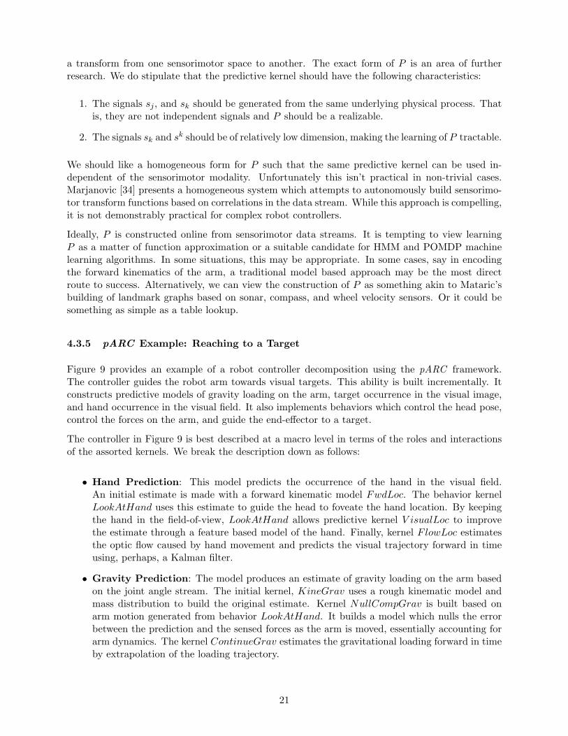
Figure 9 provides an example of a robot controller decomposition using the pARC framework.The controller guides the robot arm towards visual targets. This ability is built incrementally. Itconstructs predictive models of gravity loading on the arm, target occurrence in the visual image,and hand occurrence in the visual field. It also implements behaviors which control the head pose,control the forces on the arm, and guide the end-effector to a target.
The controller in Figure 9 is best described at a macro level in terms of the roles and interactionsof the assorted kernels. We break the description down as follows:
• Hand Prediction: This model predicts the occurrence of the hand in the visual field.An initial estimate is made with a forward kinematic model FwdLoc. The behavior kernelLookAtHand uses this estimate to guide the head to foveate the hand location. By keepingthe hand in the field-of-view, LookAtHand allows predictive kernel V isualLoc to improvethe estimate through a feature based model of the hand. Finally, kernel FlowLoc estimatesthe optic flow caused by hand movement and predicts the visual trajectory forward in timeusing, perhaps, a Kalman filter.
• Gravity Prediction: The model produces an estimate of gravity loading on the arm basedon the joint angle stream. The initial kernel, KineGrav uses a rough kinematic model andmass distribution to build the original estimate. Kernel NullCompGrav is built based onarm motion generated from behavior LookAtHand. It builds a model which nulls the errorbetween the prediction and the sensed forces as the arm is moved, essentially accounting forarm dynamics. The kernel ContinueGrav estimates the gravitational loading forward in timeby extrapolation of the loading trajectory.
21
FwdLoc
VisualLoc
FlowLoc
Hand Prediction
TargFeat
TargFlow
TargFlow
Target Prediction
BLookAtHand
HeadActuators
GravComp
AvoidSpr
HeadSpr.
ForceBehaviors
KineGrav
NullCompGrav
ContinueGrav
GravityPrediction
Track.Spr
ArmActuators
Reaching
B
B
B
B
P
P
P
P
P
P P
P
P
ImageLocalizedHand
Joint Torque
Joint Torque
Image Localized Target
JointAngles
FeatureModel
JointAngles
FeatureModel
JointAngles
AttnModel
JointAngles
Force ErrorModel
Traj.Predictor
Gravity Torque
JointAngles
Visual Servo Error
JointAngles
Figure 9: An example of a robot controller decomposition using the pARC framework. The con-troller guides the robot arm towards visual targets. This ability is built incrementally. It constructspredictive models of gravity loading on the arm, target occurrence in the visual image, and handoccurrence in the visual field. It also implements behaviors which control the head pose, controlthe forces on the arm, and guide the end-effector to a target. See the text for a more detaileddescription.
22
• Force Behaviors: These behaviors produce a joint torque stream to the arm. Behaviorkernel GravComp simply counterbalances the arm against the gravity loading signal. Thishelps minimize the position errors accumulated in the arm due to the arm dynamics and itshigh compliance. The kernel AvoidSpr simulates a set of virtual springs between the robottorso and a point on the forearm. These springs are summed on top of the gravity signal andcause the arm to avoid collisions with the body.
• Target Prediction: This model detects reaching targets in the visual field and estimates thecontinuation of their trajectory. Kernel TargFeat estimates the location of a salient objectbased on a visual feature model. The estimate is refined by applying an optic flow filterTargF low, and an attention system saliency filter TargAttn. Extrapolation of the targettrajectory in TargAttn predicts the continuation of the target in the visual field.
• Reaching: A reaching to target behavior is achieved through two layers of kernels. Thekernel HeadSpr simulates a virtual spring attached from the end-effector to a point lyingon a ray perpendicular to the image plane. While the head is tracking a target, this keepsthe hand near the target and in the visual field. The kernel TrackSpring visually servos thehand to the target in the image plane using a second virtual spring and the hand localizationinformation.
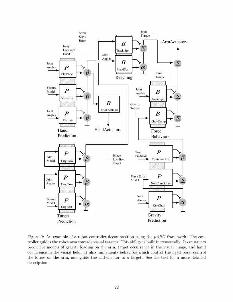
4.3.6 pARC Detailed Example: Hand Localization
To further illustrate the pARC framework, we provide a detailed description of the hand localizationcomponent from the previous example. This subsystem is depicted in Figure 10.
The controller is bootstrapped with kernel FwdLoc which uses a purely kinematic model and thecurrent robot joint angles, sj , to compute s00
k . This is the instantaneous estimate of the locationof the hand in the visual image. FwdLoc computes the target saliency as ε00 which is set to aconstant value as this is the first kernel in the model. If the hand falls outside of the image, thenε00 = 0. The kernel’s β gate will pass all signals up the afferent pathway.
The behavior LookAtHand is then implemented. It uses the signal sk to keep the hand foveatedin the center of the camera image. LookAtHand sits on the efferent pathway. Consequently, asadditional kernels are computed, LookAtHand will automatically more accurately track the camerato the future location of the hand.
The kernel V isualLoc visually identifies the hand in the image. The identification is simplifiedby utilizing the current hand estimate, sk to limit the visual search to probable locations. Thevisual identification is accomplished by a feature based model of the hand. This model is builtfrom training data gathered using the FwdLoc and LookAtHand behaviors. As the arm movesabout its workspace, due to external behaviors or by manual guidance, the camera roughly tracksits location. Overtime, a feature based model of the hand can be built as the workspace backgroundcan be subtracted out and on average the hand appears at the estimated location. The featuremodel also provides V isualLoc a quantitative means to calculate ε01 based on a statistical matchto the model. V isualLocs’s β gate can then overwrite the kinematic estimate when the modelestimate is better.
Finally, the kernel FlowLoc is implemented. This kernel inputs both the joint angles sj and thecurrent hand prediction sk. The kernel predicts the continuation of the trajectory of sk forward intime by 10 time steps. The prediction is computed using the optic flow at the hand image locationand the angular velocity of the camera. The saliency of the prediction, ε102 , is a measure of how
23

FwdLoc
VisualLoc
FlowLoc
Hand Prediction
BLookAtHand
HeadActuators
P
P
P
ImageLocalizedHand
JointAngles
FeatureModel
00
01
102
y00
y01
y102
Afferent Pathway
sk102
sk00
sk01
sk
s j
s jJointAngles
Efferent Pathway
KinematicModel
sk
Figure 10: A detailed view of the hand localization and prediction kernels. See the text for adescription.
well the kernel predicts forward in time. This value can be computed using the average predictionerror looking backwards in time. Because there are no previous predictive samples in sk, FlowLoc’sβ gate will add all of the prediction samples to the signal. The first sample of y102 , correspondingto the current hand location, will be exactly the estimate from the previous layer, and the gate willhave no effect on its value.
5 Manipulation Scenarios
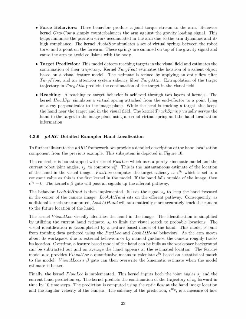
The primary research directions for Domo will be incorporated into a set of manipulation scenarios.The scenarios provide a path for the robot to incrementally acquire a richer set of behaviors, bothreactive and anticipatory. The scenarios are centered around play type activities for the robotwhich follow a developmental schema similar to a young child. The activities involve explorationsof and interactions with children’s toys and will be developed in specified stages. Following theartificial creature approach, they are integrated into a single cognitive system. The robot will becapable of discriminating between scenarios and selecting the appropriate play activity given thecurrent environmental context. The robot’s scenarios are: development of a body schema, playingtether ball with itself, playing karate sticks with a person, and putting away its toys. These are
24

Developing Body Schema
Playing Tether Ball
Playing Karate Sticks
Putting Away Toys
Hand Localization
Body Avoidance
Optic Flow Prediction
Force Prediction
Target Tracking
Reaching to Targets
Contact Prediction
Trajectory Prediction
Preshaping and Grasping
Force interactions
Turn Taking
Bimanual Coordination
Target Arbitration
Bimanual Arbitration
Transfer Operations
Advanced Grasping
Robot Developmental Time
Figure 11: The four manipulation scenarios and their principal components.
described in further detail below. Figure 11 depicts the scenarios and their principal components.For each scenario we provide an overall description including which of the nine elements of ourbehavior based decomposition it addresses. We then describe each of the basic competencies to bedeveloped, followed by a short discussion of the interesting features of the scenario.
5.1 Developing a Body Schema
Description: The initial stage of a developmental course for a humanoid robot involves activeexploration of the sensorimotor space. The explorations provide sensorimotor data fromwhich to build into the robot a sense of what its body ’feels like’. This is the notion of a bodyschema, a broadly used term to denote an egocentric view of the proprioceptive relationshipsbetween a body and its world [4]. The initial scenario for Domo involves developing a set ofbody schema modules. The modules provide anticipatory information about the relationship
25

between the robot’s actions and their sensorimotor consequences. This information providesa basis to build subsequent scenarios from.
Manipulation areas: Positioning sensors, Perception, Force operations
Hand localization: Hand localization involves estimating the occurrence of the robot hand in thevisual field. It is an essential component of visually guided manipulation and a number ofapproaches exist. A typically engineered approach models the kinematic relationship betweenthe arm pose and the camera pose. This requires accurate knowledge of the robot kinemat-ics and the camera optics. Neither of these are available to Domo. The more biologicallyplausible approach done with Babybot [43, 39] involves learning the map between arm poseand visual coordinates by training a neural network over the transform. The robot’s handis first oscillated with a fixed frequency in the visual field. By filtering the image at thatfrequency, an visual segmentation is obtained. The segmentation is repeated throughout therobot’s workspace to obtain the data set needed to train the neural network. The approachis biologically plausible as very young infants utilize a hand waving during early sensorimotordevelopment. Domo’s hand localization will be achieved by similar means.
Body avoidance: Body avoidance protects the manipulator from collisions with the robot torsoduring reaching and when an interacting human guides the arm too close to the body. It isa behavior of practical importance but also contributes to the cognitive notion of the robot’sbody schema. It grounds the representation of the robot’s trunk in terms of the manipulator.The approach taken with Domo is to apply a set of virtual springs between the manipulatorand the body. This has already been implement using a set of nonlinear springs and dampers.The force function for the springs is:
F =k
2(1 + cos(
xπ
c))− dx
where k is the spring stiffness, x is the spring length, d is the damping gain, and c is therange of influence of the spring. Outside of the range, c, the force is defined as F = 0. Thespring saturates at force F = k. The nonlinear aspect allows the springs’ force to rapidlydissipate as the manipulator moves beyond a critical collision area. There are three springbehavior types: a spring between two points, a spring between a line and a point, and aspring between a plane and a point. The spring length is computed as the minimal distancebetween the two features. At each timestep, the virtual spring force acting on the arm iscomputed and translated into joint torques. Each spring is implemented as an independentbehavior. Domo’s body avoidance is achieved by a virtual spring between the hand and thefront body plane, a spring between the forearm and the vertical corner of the torso, and aspring between the elbow and a common collision point on the side of the torso.
Force prediction: Force prediction is an efference copy mechanism, widely studied in humans [51],where an expectation of the forces encountered during ballistic movements is compared withthe real sensory experience. The expectation provides the robot with a sense of what its arms’feels like’. Violations of this expectation can be used to amplify the saliency of a stimulusand draw the robot’s attention. During interactions with objects and contact surfaces, forcepredictions can be used to modulate the stiffness of the arm. Predictive force models can bebuilt during an exploration phase. The robot explores its workspace with a set of hardwiredarm behaviors that allow it to experience a range of postures and ballistic trajectories. Thesensorimotor data from the exploration is applied to learn a map from manipulator pose andvelocity to manipulator torques. The actual torques sensed from the SEA are used as trainingdata. The map need only be roughly correct as the prediction is not used directly in a tightly
26

coupled control loop. Even knowing the correct sign of the expected manipulator torques canprovide useful information to behaviors responding to disturbances in the environment. Thelearning algorithm used in developing the map is an open research question. An additionalmodality to be developed in force prediction is a model of the gravitational loading on thearm. This can be achieved with standard robotics techniques [10].
Optic flow prediction: The optic flow induced on a robot’s camera during head and eye move-ments is a measure of the proprioceptive state of the robot and the objects found in theworld. The ability to attend to salient stimuli depends on, in part, the ability to distinguishbetween self-induced optic flow and optic flow due to externally moving objects. This is apredictive problem with biological foundations. The Vestibulo Ocular Reflex (VOR) in pri-mates generates compensatory eye movements to head motion. The reflex operates in anopen loop fashion, generating anticipatory eye movements to stabilize the image. Even withVOR, the robot will generate self-induced optic flow, and building a prediction of this flowhelps to distinguish between itself and the world. Optic flow prediction is one of the moststudied areas in robotic anticipatory systems, including robotic work with stationary texturedenvironments [52] and humanoid attentional systems [40]. A predictive model of egomotionflow can be learned based on the flow in static environments combined with the head’s kine-matic trajectory. The model can be built from purely kinematic information or learned usingstandard machine learning techniques.
Discussion: Anticipatory mechanisms at the body schema level serve two primary purposes: am-plification of salient sensory stimuli and feedforward compensation in motor control. Saliencyamplification emphasizes the relevance of sensory signals which lie outside the schema pre-dictions. Externally generated forces on the manipulator, by contact or human intervention,will conflict with the force prediction module. This conflict serves as a cue to higher level be-haviors. The same holds true for optic flow prediction. With hand localization, the predictiveestimate of the hand in the image can serve to draw attention to occlusions by objects. Thegravitational model of forces acting on the arms, and the body avoidance schema, providefeedforward signals to the robot’s motor control. These bias the control of the manipulatorto normalize against gravity and to avoid harmful collisions. The body schema modules cho-sen are tractable with respect to available analytical and machine learning techniques. Inmany cases, a lookup table may suffice. The success of each can be quantified by behavioralobservation and by measurement of the predictive error when appropriate. Optic flow andforce prediction can be measure by the ability to amplify external stimuli from egomotiongenerated stimuli. Body avoidance can be analyzed in terms of the manipulator workspacecovered during random movements. The hand localization module can be studied in terms ofits robustness to occlusions and its ability to match its prediction to a known hand locationgained from oscillatory motion.
5.2 Playing Tether Ball
Description: Tether ball is playground game where a child bats at a moving ball with herhands. The ball is suspended from a pole by a rope. It is a game of basic visual and motorcoordination that can be used as a constrained task for Domo to interact with the world in astructured manner. The ball is on a rope and will always, eventually, return to a set postion.This enables the robot to play the game without human intervention over long periods oftime. It allows for extended interactions to generate sensorimotor data which, in turn, can beused to refine the body schema models from the previous scenario. It may also be played with
27

one or two hands and provides opportunity to investigate simple bimanual action selection.
Manipulation areas: Positioning sensors, Perception, Force operations, Detecting failures
Target tracking: The first necessary component is a robust means of tracking a target, whichin this case is a ball. The tracking involves performing an initial segmentation of the targetfrom the environment, and also tracking its continuation between visual frames. The trackingcan be accomplished with well established techniques such as the Lucas-Kanade Tracker [33].The tracking involves an active coupling between the head pose and the object as well. In thespecific case of a ball, simple template and color histogram models suffice to reliably segmentthe object. Additional depth information can be derived using the pixel based size of theball. In this manner, Domo’s visual system can be bootstrapped to investigate the principalproblem of visual-motor coordination. A more general approach to object segmentation andtracking will be needed for later scenarios.
Reaching to targets: Robot reaching to visual targets is a well studied area, both from an engi-neering perspective [10] and a biological perspective [43]. In the case of Domo, this involvesa mapping a trajectory from the image localized target to the 4 DOF in the shoulder andelbow. The wrist is treated independently from the upper arm. Reaching which incorporatesapproach planning is deferred until a later scenario. Clearly, a traditional approach utilizinginverse kinematics could work. However, the compliance in Domo’s arms would introducelarge offset errors. Additionally, this would require an precise model of the arm kinematicsand of the target location. We propose investigating a hybrid approach utilizing feedforwardjoint postures and a Virtual Model controller. The sensorimotor exploration of the previousscenario can be used to build a simple map from visual coordinates to joint angles. A trajec-tory generation mechanism can then be used in a behavior which keeps the hand in the visualimage using this feedforward map. If the robot is fixating the target and the hand is in thevisual image, then VMC springs can be applied to visually servo the hand to the target (orits expected location). A related hybrid approach was used with the humanoid DB [19].
Trajectory prediction: The trajectory of the ball on the rope should follow a smooth pathbetween external contacts. Predicting the continuation of this trajectory is critical to therobots ability to swing at the moving ball. This is a well constrained and structured problem.It involves predicting the time series continuation of a three dimensional signal. A generalapproach to this problem can be applied to other predictive domains for Domo as well. Twoproposed areas of investigation are Kalman filters and temporal difference learning [53].
Contact prediction: Playing tether ball requires a turn-taking interaction between the robot andthe ball. Contact is made and then the ball is allowed decelerate before contact is made again.Constructing transition points in the turn-taking requires prediction of contact. Contactprediction involves both detection of manipulator contact with the ball and anticipation ofthe event. Contact detection can be determined from models of the velocity and accelerationof the target. Conflicts with the underlying manipulator force schema can also be used todetect collisions. Anticipation of contact can achieved with similar methods to those used fortrajectory prediction.
Discussion: This scenario builds off of many of the competencies gained in the body schema sce-nario. It is particularly interesting in that it affords a long duration sensorimotor experienceto the robot which involves anticipatory visual motor coordination. This opens up an oppor-tunity for on-line learning of how to best modulate the reaching strategy for the manipulator.One approach would be to use reinforcement learning to best modulate a set of reaching
28

behaviors. The success of the control strategy is readily quantified by the error in hand totarget position. The scenario involves challenging technicalcal subproblems but these canlikely be addressed independently with different techniques. The realtime visual localizationof the target in space is greatly simplified by the target type. This allows the scenario to focuson the development of the predictive components and incorporating the predictions into themanipulator control strategy.
5.3 Playing Karate Sticks
Description: Karate sticks is a children’s game derived from Filipino stick fighting. Each childholds a broomstick type rod between two hands at about a shoulder’s width apart. They playby thrusting their stick at the other in order to make contact between the two sticks. Thegoal is to read the orientation of the other’s stick and match it such that the two sticks makecontact at orthogonal orientations at approximately the center of the stick. In this scenariowith Domo, a human would present the stick to the robot. The robot would reach and makea bimanual grasp of the stick at the appropriate locations. The human robot would then playthe game with the robot predicting the pose of the human’s stick at the time of contact. Thisleverages on the competencies of the tether ball scenario.
Manipulation areas: Positioning sensors, Perception, Grasping, Force operations, Detecting fail-ures
Preshaping and grasping: The scenario requires development of simple predictive grasp pre-shaping based on the stick orientation. When the human presents the stick for play, thecorrect grasp shape and manipulator approach needs to be formed. This is a constrainedversion of the more general, and important, issue of grasp preshaping in that only a homo-geneous power grasp is needed to grasp a cylinder along its axis. The hands on Domo arelimited in the dexterity of grasps available and this task represents a good match betweenthe capabilities of the hands and the exploration of preshaping abilities. However, this pre-shaping task requires robust identification of the object pose as well selection among differingapproaches and grasp shapes depending on the object orientation. One method previouslydemonstrated on Domo is to build a look-up table map from image pose to hand and wristpose.
Force interactions: Force interactions occur throughout the scenario, between the two arms andthe stick, and between the two sticks. One mode of play involves maintaining stick contactwhile taking turns pushing on the opponents stick. This can be achieved by a VMC behaviorwhich modulates manipulator endpoint forces at a given stick orientation. A second featureof the the force interactions is demonstrated by the relatively high contact forces which occurbetween the two sticks during play. The compliance in the manipulator accommodates thisnaturally and protects the robot geartrain. The force sensing provides a means of detectionof contact, and consequently, anticipation of contact. In turn, the stiffness of the manipulatorarms can be modulated by this anticipation.
Bimanual coordination: The scenario requires coordination between the two arms while adjust-ing the orientation of the robot’s stick. When the desired orientation has been achieved, afixed action pattern thrusting of the stick can occur, contingent on the turn taking natureof the game. The robot interweaves a stick orientation behavior and a thrusting behavior.The orientation behavior can take advantage of the force controlled nature of the arms. Amechanical force coupling occurs between the arms through the stick. As one arm leads a
29

motion, the other can naturally adapt through the interaction forces with the stick. Becausethe joint angles are only controlled through the force controllers, and because the arms arecompliant, precise coordination of the arms should not be necessary.
Turn taking: Karate sticks requires turn taking between the human and robot. Typically oneplayer can lead the play by deciding when to thrust the stick and the other follows. Oneplayer also entrains the orientation of their stick to the other. In this manner, a humanplaying with the robot can lead the play interaction fruitfully. If the robot chooses theincorrect stick pose or an inopportune moment to thrust its stick, the human will naturallyadapt its turntaking to follow. In this manner, the human-robot interaction scaffolds the playactivity into one that is richer than the robot’s abilities allows. The robot needs to read theorientation of the human’s stick, a constrained visual problem given the simple geometry ofthe object. For richer turn taking to occur, the robot needs to predict the continuation of thestick trajectory and anticipate the thrusting of the stick.
Discussion: This scenario demonstrates a tight coupling between the robot and the world throughinteraction forces. It capitalizes on many of the features unique to the manipulators developedfor the robot. Visual perception during the task is constrained to recognizing the stick poseand also possibly detection and tracking of the human’s face, both of which are tractableproblems. It allows an exploration of bimanual, force-based manipulation. It also providesan opportunity to explore human-robot turn taking during manipulation, where the turn-taking is driven by the manipulation interaction forces. One risk is that the robot’s handsare not strong enough to maintain a stable grasp on the stick. In the case that it is dropped,the play can continue as the robot should be able to reach and regrasp the stick when it isofferred. The success of the scenario can be measured in the ability to match the human’sstick orientation, the speed at which Domo can play the game, and the robustness of itspreshaping and grasping behaviors.
5.4 Putting Away Toys
Description: This scenario of putting away toys is designed to incorporate elements of the threepreceding scenarios and to generalize some of the perceptual and motor competencies intobehaviors which operate in less structured environments. It involves the robot picking upobjects from a table and placing them in a box. The objects are heterogeneous in size, shape,color, and texture. They are positioned on the table in an arbitrary fashion and may overlapand occlude one another. The box can be placed anywhere in the robot’s reachable workspace.
Manipulation areas: Deciding on actions, Positioning sensors, Perception, Grasping, Force op-erations, Transfer, Disengaging, Detecting failures
Target arbitration: Target arbitration requires selecting an object, among many, on the tableto grasp. This is a perceptually difficult problem, and a combination of techniques can beemployed without requiring a full visual reconstruction of the object. Fitzaptrick et al. [17]approached the perceptual problem by having the robot poke at objects in the environment.The optic flow generated from the poking allowed a clean segmentation of the object from thebackground. A second approach to visual segmentation based on texture cues [29], developedin our lab, will be employed to segment homogeneous regions of texture from the image. Acombination of the two approaches should allow Domo to determine a number of regions ofinterest for grasping. Arbitration among objects requires determining which object to reachfor based on a saliency metric. The metric is computed from a set of hardwired ’graspability’
30

cues such as size and, depth, and segmentation confidence. The arbitrator need also detectfailures during grasping based on tactile and visual cues. Detection of a failure can allow asecond attempt at grasping or allow a different object to be attempted.
Bimanual arbitration: Domo can use one or two hands to grasp an object on the table. Arbitra-tion between single and two handed manipulation can be accomplished based on a predictivemodule which embeds the relationship between a set of visual features (size, roundness, etc)and the expected success using one or two hands. The module can be built through a setof prior manipulation engagements with objects where both types of manipulation are at-tempted. The bimanual coordination developed in the previous scenario can then be general-ized to a richer set of objects, where the interaction forces between the two manipulators canbe used to form a full armed pincer type grasp. Detection of single handed grasping failurecan be used to signal the arbitrator to reattempt using a bimanual approach.
Advanced grasping: Grasp preshaping in the previous scenario was limited to orienting the wristcorrectly in order to form a cylinder grasp on the stick. Preshaping is a fundamental antic-ipatory behavior used during manipulation. Domo has 1 DOF in the hand 2 DOF in thewrist which can be used to precondition the hand’s engagement with an object. The limiteddexterity of the hand still affords a rich set of preshapes. A simple approach to preshaping,already implemented on the robot, maps the object’s primary orientation axis to a fixed setof hand postures. The mapping is hand coded and brittle. The approach can be expandedto use a prior set of manipulation engagements to build the map from. A coarse estimateof the grasp’s correctness can be calculated from the total tactile sensation. This can beused to bias the map from visual features to hand postures in the appropriate direction.A primary grasping ability to be developed is distinguishing between grasp-from-above andgrasp-from-the-side approaches to the object.
Transfer operations: The final component of the scenario is transferring a grasped object to theopen box. The box can be visually localized base on its geometry, and the transfer can becompleted by the previous reach-to-target behavior. An interesting extension is to incorporatelocally guided path planning during the transfer. With basic depth cues from the objects onthe table, a set of avoidance springs, as used in the body avoidance module, can be added tomove the manipulator around protruding objects.
Discussion: This scenario is the least constrained and therefore the most challenging of the four.It allows exploration of the coupling between visual features, prior manipulation experience,and action planning. The set of objects available to the robot cannot be completely generalgiven the limitations of the robot’s hands. However the variety of objects used can illustrateanticipatory aspects of the preshaping and bimanual behaviors. The visual processes can bedeveloped largely with existing software, but the success of the scenario depends largely onthe ability to segment out the countours of individual objects. This success can be measuredin the adaptability to different types of objects, the speed of execution, and the ability toform appropriate grasp preshapes and bimanual arbitrations.
6 Milestones and Timeline
The following milestones will be accomplished:
31

Date MilestoneSeptember 2004 Design, fabrication, and assembly of Domo.December 2004 Testing of low-level controllers.January 2005 Development multi-processor real-time control architecture and nec-
essary software infrastructure.February 2005 Integration of existing vision code into software infrastructure.March 2005 Development of initial pARC software framework.June 2005 Development of the Body Schema scenarioSeptember 2005 Development of the Playing Tether Ball scenarioDecember 2006 Development of the Playing Karate Sticks scenarioMarch 2006 Development of the Putting Away Toys scenarioJune 2006 Collection of experimental data. Completion of writing of disserta-
tion.
32

References
[1] Ronald Arkin. Behavior Based Robotics. MIT Press, 1998.
[2] A. Arsenio and P. Fitzpatrick. Exploiting cross-modal rhythm for robot perception of objects.In Proceedings of the Second International Conference on Computational Intelligence, Robotics,and Autonomous Systems, December 2003.
[3] Lijin Aryananda and Jeff Weber. MERTZ: A Quest for a Robust and Scalable Active VisionHumanoid Head Robot. In Proceedings, IEEE-RAS International Conference on HumanoidRobotics, Santa Monica, Los Angeles, CA, USA., 2004. IEEE Press.
[4] Jose Bermudez, Anthony Marcel, and Naomi Eilan, editors. The Body and the Self. The MITPress, Cambridge, Mass., 1995.
[5] Cynthia Breazeal. Sociable Machines: Expressive Social Exchange Between Humans andRobots. PhD thesis, MIT, Cambridge, Ma, June 2000.
[6] R. Brooks. Challenges for complete creature architectures. In Proceedings of Simulation ofAdaptive Behavior (SAB90), 1990.
[7] Rodney Brooks, Rodric Grupen, and Robert Ambrose. Autonomous Manipulation Capabilitiesfor Space and Surface Operations. Proposal to NASA in response to BAA-04-02, October 2004.
[8] Rodney A. Brooks. A robust layered control system for a mobile robot. IEEE Journal ofRobotics and Automation, RA-2:14–23, April 1986.
[9] Rodney A. Brooks, Cynthia Breazeal, Matthew Marjanovic, Brian Scassellati, and Matthew M.Williamson. The Cog project: Building a humanoid robot. In C. L. Nehaniv, editor, Compu-tation for Metaphors, Analogy and Agents, volume 1562 of Springer Lecture Notes in ArtificialIntelligence. Springer-Verlag, 1999.
[10] J. Craig. Introduction to Robotics. Addison Wesley, 2 edition, 1989.
[11] E. Datteri, G. Teti, C. Laschi, G. Tamburrini, P. Dario, and E. Guglielmelli. Expectedperception: an anticipation-based perception-action scheme in robots. In Proceedings of theIEEE/RSJ International Conference on Intelligent Robots and Systems (IROS-03), volume 1,pages 934–939, Las Vegas, NV, Oct 2003.
[12] P. Davidson and D.M. Wolpert. Motor learning and prediction in a varialbe environment.Current Opinion in Neurobiology, 13:1–6, 2003.
[13] Aaron Edsinger-Gonzales. Design of a Compliant and Force Sensing Hand for a HumanoidRobot. In Proceedings of the International Conference on Intelligent Manipulation and Grasp-ing, July 2004.
[14] P. Fitzpatrick, G. Metta, L. Natale, S. Rao, and G. Sandini. Learning About Objects ThroughAction: Initial Steps Towards Artificial Cognition. In Proceedings of the 2003 IEEE Interna-tional Conference on Robotics and Automation (ICRA), Taipei, Taiwan, May 2003.
[15] Paul Fitzpatrick. From First Contact to Close Encounters: A developmentally deep perceptualsystem for a humanoid robot. PhD thesis, Massachusetts Institute of Technology, 2003.
[16] Paul Fitzpatrick and Giorgio Metta. YARP: Yet Another Robot Platform. MIT ComputerScience Artificial Intelligence Laboratory, http://sourceforge.net/projects/yarp0, 2004.
33

[17] Paul Fitzpatrick, Giorgio Metta, Lorenzo Natale, Sajit Rao, and Giulio Sandini. Learningabout objects through action - initial steps towards artificial cognition. In Proceedings of the2003 IEEE International Conference on Robotics and Automation (ICRA-03), volume 3. IEEEPress, 2003.
[18] J.R. Flanagan, S. King, D.M. Wolpert, and R.S. Johansson. Sensorimotor prediction andmemory in object manipulation. Canadian Journal of Experimental Psychology, 55:89–97,2001.
[19] Chris Gaskett and Gordon Cheng. Online Learning of a Motor Map for Humanoid RobotReaching. In Proceedings of the 2nd International Conference on Computational Intelligence,Robotics and Autonomous Systems (CIRAS 2003), Singapore, December 2003.
[20] H. Gomi and M. Kawato. Human arm stiffness and equilibrium-point trajectory during multi-joint muscle movement. Biological Cybernetics, 76:163–171, 1997.
[21] R. Grupen and C Coelho. Structure and Growth: A Model of Development for Grasping withRobot Hands. In Proceedings of the IEEE/RSJ International Conference on Intelligent Robotsand Systems (IROS 2000)s, Takamatsu, Japan, November 2000.
[22] Kuzanuao Uchiyama Haruhisa Kawasaki, Tsuneo Komatsu. Dexterous anthropomorphic robothand with distributed tactile sensor: Gifu hand ii. IEEE Transactions on Mechatronics,7(3):296–303, September 2002.
[23] Horst Hendriks-Jansen. Catching Ourselves in the Act. MIT Press, Cambridge, Mass., 1996.
[24] T. L. Huntsberger, H. Aghazarian, E. Baumgartner, and P. S. Schenke. Behavior-based con-trol systems for planetary autonomous robot outposts. In Proceedings of Aerospace 2000,Albuquerque, NM, 2000.
[25] Point Grey Research Inc. FireFly2 IEEE-1394 CCD Camera Manual.”http://www.ptgrey.com/products/firefly2/firefly2.pdf”, 2004.
[26] P. Dilworth J. Pratt, M. Chew and G. Pratt. Virtual Model Control: An Intuitive Approachfor Bipedal Locomotion. International Journal of Robotics Research, 20(2):129–143, 2001.
[27] Roderic A. Grupen Jefferson A. Coelho Jr., Justus H. Piater. Developing Haptic and VisualPerceptual Categories for Reaching and Grasping with a Humanoid Robot. In Proceedings ofthe First IEEE-RAS International Conference on Humanoid Robots, Cambridge, MA, USA,September 2000.
[28] E. R. Kandel, J. H. Schwartz, and T. Jessell. Principles of Neural Science. McGraw-Hill andAppleton and Lange, New York, NY, 4th edition, January 2000.
[29] Charlie Kemp. Duo: A Human/Wearable Hybrid for Learning About Common ManipulableObjects. In Proceedings, IEEE-RAS International Conference on Humanoid Robotics. IEEEPress, 2003.
[30] Oussama Khatib. A unified approach to motion and force control of robot manipulators: Theoperational space formulation. International Journal of Robotics and Automation, 3(1):45–53,1987.
[31] K. Kording and D.M. Wolpert. Bayesian integration in sensorimotor learning. Nature, 427:244–247, 2004.
34

[32] C. Lovchik and M. Diftler. The robonaut hand: A dexterous robot hand for space. In Pro-ceedings of the IEEE International Conference on Automation and Robotics, volume 2, pages907–912, Detroit, Michigan, May 1999.
[33] Bruce D. Lucas and Takeo Kanade. An iterative image registration technique with an ap-plication to stereo vision. In International Joint Conference on Artificial Intelligence, pages674–679, 1981.
[34] Matthew J. Marjanovic. Teaching an Old Robot New Tricks: Learning Novel Tasks via Inter-action with People and Things. PhD thesis, MIT, Cambridge, Ma, 2003.
[35] Matthew Mason. Mechanics of Robotic Manipulation. MIT Press, August 2001. IntelligentRobotics and Autonomous Agents Series, ISBN 0-262-13396-2.
[36] Maja J Mataric. Integration of representation into goal-driven behavior-based robots. EEETransactions on Robotics and Automation, 8(3):304–312, June 1992.
[37] Maja J Mataric and Rodney A. Brooks. Cambrian Intelligence, chapter Learning a DistributedMap Representation Based on Navigation Behaviors, pages 37–58. MIT Press, 1999.
[38] J. McIntyre and E. Bizzi. Servo hypotheses for the biological control of movement. Journal ofMotor Behavior, 25:193–203, 1993.
[39] Giorgio Metta. Babybot: a study into sensorimotor development. PhD thesis, LIRA-Lab,DIST, University of Genoa, 2000.
[40] Giorgio Metta. An attentional system for a humanoid robot exploiting space variant vision.In IEEE-RAS International Conference on Humanoid Robots, 2001.
[41] R. Moller. Perception through anticipation - an approach to behavior-based perception. InProceedings of New Trends in Cognitive Science, pages 184–190, Vienna, Austria, 1997.
[42] Hans Moravec. The Stanford Cart and the CMU Rover. In I. J. Cox and G. T. Wilfong,editors, Autonomous Robot Vehicles, pages 407–41. Springer-Verlag, 1990.
[43] Lorenzo Natale. Linking Action to Perception in a Humanoid Robot: A Developmental Ap-proach to Grasping. PhD thesis, LIRA-Lab, DIST, University of Genoa, 2004.
[44] Robert Platt, Oliver Brock, Andrew H. Fagg, Deepak R. Karuppiah, Michael T. Rosenstein,Jefferson A. Coelho Jr., Manfred Huber, Justus H. Piater, David Wheeler, and Roderic A.Grupen. A Framework For Humanoid Control and Intelligence. In Proceedings of the 2003IEEE International Conference on Humanoid Robots, 2003.
[45] G. Pratt and M. Williamson. Series Elastic Actuators. In Proceedings of the IEEE/RSJInternational Conference on Intelligent Robots and Systems (IROS-95), volume 1, pages 399–406, Pittsburg, PA, July 1995.
[46] Jerry Pratt. Exploiting Inherent Robustness and Natural Dynamics in the Control of BipedalWalking Robots. Ph.d., Massachusetts Institute of Technology, Cambridge, Massachusetts,2000.
[47] Jerry E. Pratt. Virtual Model Control of a Biped Walking Robot. Technical Report AITR-1581, MIT Artificial Intelligence Laboratory, 1995.
35

[48] T. Prescott, P. Redgrave, and K. Gurney. Layered control architectures in robots and verte-brates. Adaptive Behavior, 7:99–127, 1999.
[49] A.M. Ramos and I.D. Walker. Raptors-Inroads to Multifingered Grasping. In Proceedings ofthe IEEE/RSJ International Conference on Intelligent Robots and Systems, pages 467–475,1998.
[50] Brian Scassellati. Foundations for a Theory of Mind for a Humanoid Robot. PhD thesis,Massachusetts Institute of Technology, 2001.
[51] D.M. Wolpert S.J. Blakemore, C.D. Frith. The cerebellum is involved in predicting the sensoryconsequences of action. NeuroReport, 12(11):1879–1884, July 2001.
[52] V. Stephan and H.M Gross. Neural anticipative architecture for expectation driven perception.IEEE International Conference on Systems, Man, and Cybernetics, 4:2275–2280, 2001.
[53] R.S. Sutton. Learing to Predict by Methods of Temporal Differences. Machine Learning,3(1998):9–44, 1988.
[54] W. T. Townsend and Salisbury. ”Robots and biological systems : towards a new bionics?”,chapter Mechanical design for wholearm manipulation. Springer-Verlag, 1993.
[55] William Townsend. The BarrettHand Grasper. Industrial Robot: and International Journal,27(3):181–188, 2000.
[56] Todd W. Troyer and Allison J. Doupe. An associational model of birdsong sensorimotorlearning i. efference copy and the learning of song syllables. JNPHY, 84(3):1204–1223, 2000.
[57] E. von Holst and H. Mittelstae. The Behavioural Physiology of Animals and Man: The Col-lected Papers of Erich von Holst, chapter The reafference principle. (1950). University of MiamiPress, Coral Gables, FL, 1973.
[58] Matt Williamson. Neural control of rhythmic arm movements. Neural Networks, 11(7-8):1379–1394, 1998.
[59] A. Witney, S.J. Goodbody, and D.M. Wolpert. Learning and decay of prediction in objectmanipulation. Journal of Neurophysiology, 84:334–343, March 2000.
36

A The Robot Platform
Domo, as pictured in Figure 1, has 29 active degrees of freedom (DOF), 58 proprioceptive sensors,and 24 tactile sensors. 22 DOF use force controlled and compliant actuators. There are two sixDOF force controlled arms, two four DOF force controlled hands, a two DOF force controlledneck, and a seven DOF active vision head. The real-time sensorimotor system is managed by anembedded network of five DSP controllers. The vision system includes two FireWire CCD cameras[25] and utilizes the YARP [16] software library for visual processing. The cognitive system runson a small, networked cluster of PCs running the Linux operating system.
A.1 Head
A
B
C
D
Figure 12: Mechanical drawing of Domo’s active vision head. A SEA driven universal joint (B)combined with head pan (C) provides a compact ball-and-socket like three DOF neck. The upperneck provides roll and tilt through a cable-drive differential (A). Two FireWire CCD cameras (D)share a single tilt DOF and have two independent pan DOF. Expressive eyelids provide a final DOF.
The design of Domo’s active vision head is an evolution from previous designs used for the robotsCog and Kismet [9, 5]. It is a copy of the head used in a new active vision project by Aryananda[3].
The head features 7 DOF in the upper head, a 2 DOF force controlled neck, and a stereo pairof FireWire CCD cameras. The upper head provides roll and tilt through a compact cable-drivedifferential. The two cameras share a single tilt DOF and have 2 independent pan DOF. The headalso features one DOF expressive eyelids.
The head uses brushed DC motors with both encoder and potentiometer position feedback. The
37

potentiometers allow for absolute measurement of position at startup, eliminating the need forstartup calibration routines. The analog signal from the CCD cameras is digitized to a FireWireinterface on boards mounted in the head, reducing noise issues related to running the camera signalsnear the head’s motors. Physical stops are incorporated into all DOF to safeguard the head againstpotential software failures.
Unlike Cog’s head which used one wide and one foveal camera per eye, Domo uses a single wideangle camera per eye. The camera used is the Point Grey OEM Dragonfly [25]. The cameras areIEEE-1394 FireWire devices with 640x480 (30fps) or 1024x768 (15fps) 24-bit color resolution. Weuse a 2mm focal length lens. The cameras are powered by the FireWire bus and provide softwarebased synchronization of the dual framegrabbers.
Our primary design consideration for the upper portion of the head is that it be able to executehuman-like eye movement. Human eye movements can be classified as: saccades, smooth pursuit,vergence, vestibulo-ocular reflex, and the optokinetic response [28]. Domo’s head is designed toaccommodate all but the optokinetic response. Saccades require fast, ballistic movements of theeyes (900deg/s) while smooth pursuit requires slow, controlled tracking movements of less than100deg/s. Vergence requires independent control of the eye pan to view objects of varying depth.The vestibulo-ocular reflex requires either a head mounted gyroscope or correct kinematic informa-tion (we currently use the latter). Accommodating these features required careful design of the eyedrive system and motor selection. We use a small gearhead motor (Maxon 8mm 0.5W with 57:1gearhead) and an efficient cable-drive system for the eye pan.
A.2 Arms
B
A
C D E
F
Figure 13: The kinematic structure of Domo’s arms. A compact cable-drive differential at theshoulder provides pitch (A) and roll (B). These two DOF are driven by actuators placed in therobot torso. The bicep of the arm contains four other actuators: shoulder yaw (C), elbow pitch (D),and wrist roll (E) and pitch (F) driven by two cables routed through the elbow.
Traditional arm designs assume that end-effector stiffness and precision are necessary qualities. Acentral pillar of our design approach to Domo’s arms is that the manipulators must be passivelyand actively compliant and able to directly sense and command torques at each joint.
Each arm joint is driven by an SEA containing a brushless DC motor. SEAs and FSCAs are coveredin Section 2. As shown in Figure 13, a compact cable-drive differential at the shoulder providespitch and roll. These two DOF are driven by actuators placed in the robot torso. The bicep of the
38
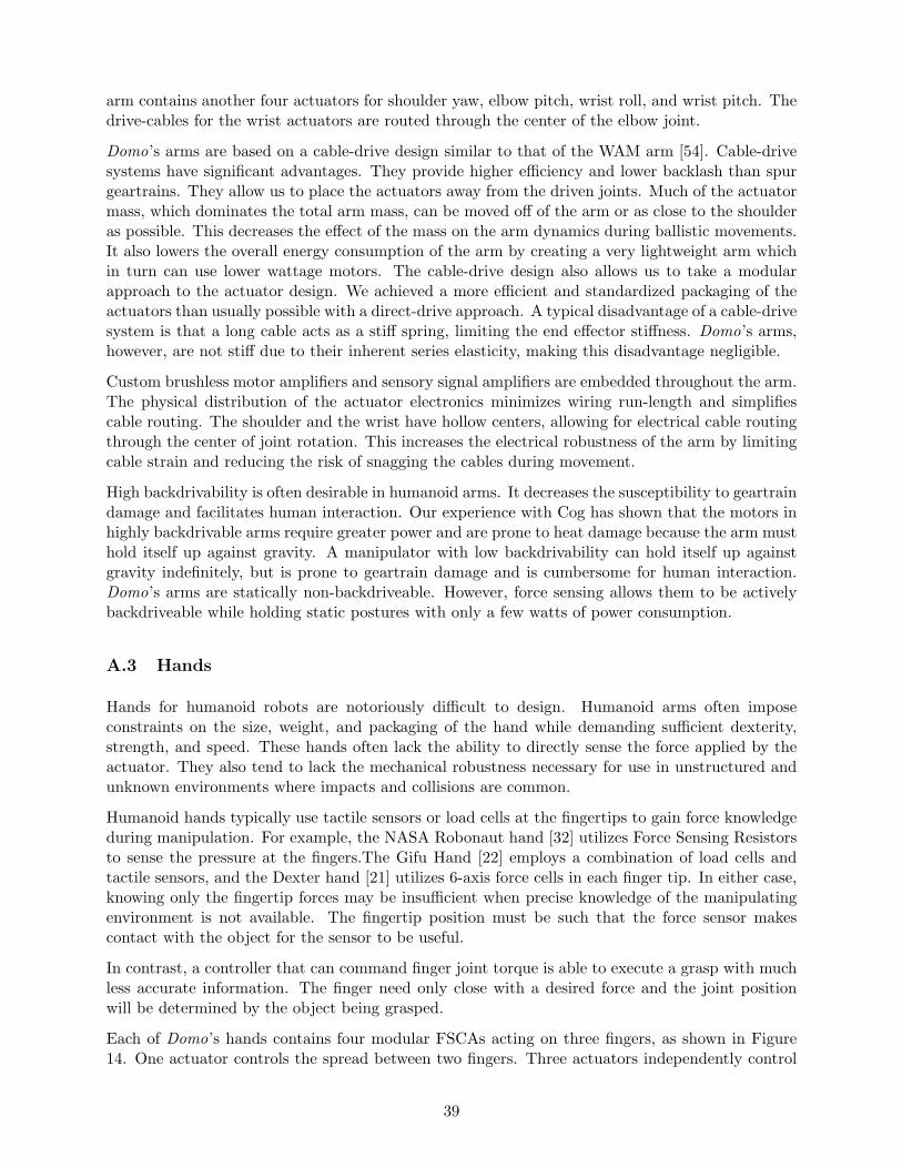
arm contains another four actuators for shoulder yaw, elbow pitch, wrist roll, and wrist pitch. Thedrive-cables for the wrist actuators are routed through the center of the elbow joint.
Domo’s arms are based on a cable-drive design similar to that of the WAM arm [54]. Cable-drivesystems have significant advantages. They provide higher efficiency and lower backlash than spurgeartrains. They allow us to place the actuators away from the driven joints. Much of the actuatormass, which dominates the total arm mass, can be moved off of the arm or as close to the shoulderas possible. This decreases the effect of the mass on the arm dynamics during ballistic movements.It also lowers the overall energy consumption of the arm by creating a very lightweight arm whichin turn can use lower wattage motors. The cable-drive design also allows us to take a modularapproach to the actuator design. We achieved a more efficient and standardized packaging of theactuators than usually possible with a direct-drive approach. A typical disadvantage of a cable-drivesystem is that a long cable acts as a stiff spring, limiting the end effector stiffness. Domo’s arms,however, are not stiff due to their inherent series elasticity, making this disadvantage negligible.
Custom brushless motor amplifiers and sensory signal amplifiers are embedded throughout the arm.The physical distribution of the actuator electronics minimizes wiring run-length and simplifiescable routing. The shoulder and the wrist have hollow centers, allowing for electrical cable routingthrough the center of joint rotation. This increases the electrical robustness of the arm by limitingcable strain and reducing the risk of snagging the cables during movement.
High backdrivability is often desirable in humanoid arms. It decreases the susceptibility to geartraindamage and facilitates human interaction. Our experience with Cog has shown that the motors inhighly backdrivable arms require greater power and are prone to heat damage because the arm musthold itself up against gravity. A manipulator with low backdrivability can hold itself up againstgravity indefinitely, but is prone to geartrain damage and is cumbersome for human interaction.Domo’s arms are statically non-backdriveable. However, force sensing allows them to be activelybackdriveable while holding static postures with only a few watts of power consumption.
A.3 Hands
Hands for humanoid robots are notoriously difficult to design. Humanoid arms often imposeconstraints on the size, weight, and packaging of the hand while demanding sufficient dexterity,strength, and speed. These hands often lack the ability to directly sense the force applied by theactuator. They also tend to lack the mechanical robustness necessary for use in unstructured andunknown environments where impacts and collisions are common.
Humanoid hands typically use tactile sensors or load cells at the fingertips to gain force knowledgeduring manipulation. For example, the NASA Robonaut hand [32] utilizes Force Sensing Resistorsto sense the pressure at the fingers.The Gifu Hand [22] employs a combination of load cells andtactile sensors, and the Dexter hand [21] utilizes 6-axis force cells in each finger tip. In either case,knowing only the fingertip forces may be insufficient when precise knowledge of the manipulatingenvironment is not available. The fingertip position must be such that the force sensor makescontact with the object for the sensor to be useful.
In contrast, a controller that can command finger joint torque is able to execute a grasp with muchless accurate information. The finger need only close with a desired force and the joint positionwill be determined by the object being grasped.
Each of Domo’s hands contains four modular FSCAs acting on three fingers, as shown in Figure14. One actuator controls the spread between two fingers. Three actuators independently control
39
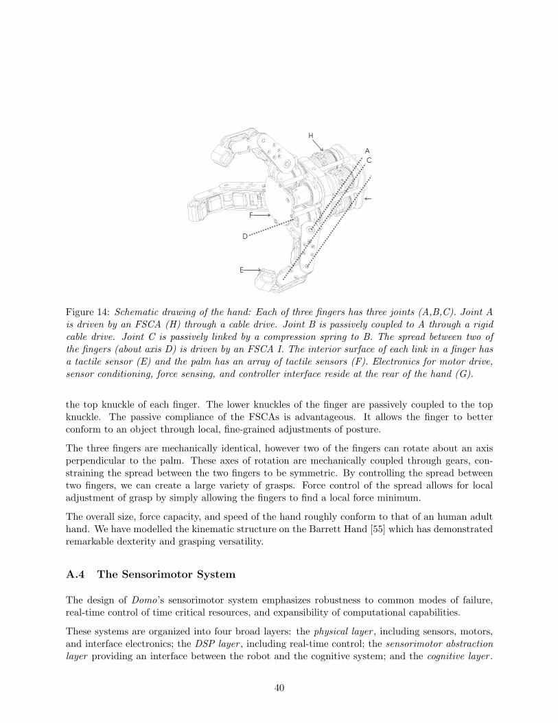
A
C
D
E
F
H
Figure 14: Schematic drawing of the hand: Each of three fingers has three joints (A,B,C). Joint Ais driven by an FSCA (H) through a cable drive. Joint B is passively coupled to A through a rigidcable drive. Joint C is passively linked by a compression spring to B. The spread between two ofthe fingers (about axis D) is driven by an FSCA I. The interior surface of each link in a finger hasa tactile sensor (E) and the palm has an array of tactile sensors (F). Electronics for motor drive,sensor conditioning, force sensing, and controller interface reside at the rear of the hand (G).
the top knuckle of each finger. The lower knuckles of the finger are passively coupled to the topknuckle. The passive compliance of the FSCAs is advantageous. It allows the finger to betterconform to an object through local, fine-grained adjustments of posture.
The three fingers are mechanically identical, however two of the fingers can rotate about an axisperpendicular to the palm. These axes of rotation are mechanically coupled through gears, con-straining the spread between the two fingers to be symmetric. By controlling the spread betweentwo fingers, we can create a large variety of grasps. Force control of the spread allows for localadjustment of grasp by simply allowing the fingers to find a local force minimum.
The overall size, force capacity, and speed of the hand roughly conform to that of an human adulthand. We have modelled the kinematic structure on the Barrett Hand [55] which has demonstratedremarkable dexterity and grasping versatility.
A.4 The Sensorimotor System
The design of Domo’s sensorimotor system emphasizes robustness to common modes of failure,real-time control of time critical resources, and expansibility of computational capabilities.
These systems are organized into four broad layers: the physical layer , including sensors, motors,and interface electronics; the DSP layer , including real-time control; the sensorimotor abstractionlayer providing an interface between the robot and the cognitive system; and the cognitive layer .
40

The first two layers are physically embedded on the robot while the latter two are processes runningon the Linux cluster. The cognitive layer is the subject of Section 4.
A.4.1 Physical Layer
The physical layer is made up of the electromechanical resources physically embedded in the robot.This includes: 12 brushless DC motors and amplifiers in the arms, 17 brushed DC motors andamplifiers in the hands and head, a force sensing potentiometer at each of the 22 force controlledjoints, a position sensing potentiometer at each of the 29 joints, a position sensing encoder at eachof the 7 joints in the upper head, and an array of 12 FSR tactile sensors in each hand.
Our primary considerations in the design of the physical layer are the electromechanical robustnessover time and the reduction of sensor noise.
Potentiometers tend to be noisy sensors. Each potentiometer sensor and FSR sensor on Domohas a signal conditioning amplifier mounted near the sensor. The amplifier provides both signalamplification and a passive low-pass filter to help reduce signal noise that may be picked up fromlong cable runs near the motors. The brushless motors used throughout the arms, where Domoencounters the longest cable runs, radiate less noise than brushed motors. In the head, the poten-tiometers are only sampled at startup to get the absolute position of the head for calibration, afterwhich the encoders are used for position sensing. In the hand, we keep the cable run for the sensorsas short as possible by placing the DSP controller node in the wrist.
The arm and hand motor amplifiers are embedded through out the arm (in contrast to the robotCog, where they were kept off-board). The small form-factor custom amplifiers provide optoiso-lation between the motor and the controllers, 20Khz PWM switching, and current sensing andlimiting. By embedding the amplifiers, we limit the noise creating inductive effect of switchinghigh currents through long cables.
A.4.2 DSP Layer
The DSP layer provides real-time control over sensor signal acquisition and motor control. Thelayer currently incorporates five DSP nodes each running a 40Mhz Motorola DSP56F807. Thenodes are mounted in the back of Domo’s torso. Each node communicates with the sensorimotorabstraction layer through a 1Mbps CAN bus channel. The number of nodes and the number ofCAN bus channels is extensible as the sensorimotor requirements of the robot increase.
By using embedded DSP controllers, we gain complete control over the real-time aspects of thesensorimotor system. This avoids pitfalls commonly encountered when using PC based controllers,which can suffer from operating system timeouts and complicated startup routines. In contrast,the DSP controller starts up with a single switch and can safely function as a stand-alone unit.
Each DSP node controls up to eight joints in a 1Khz control loop. It also reads up to 16 analogsensor signals at 1Khz. The arm and hand nodes provide force control loops while the head nodeprovides position and velocity control. Higher level controllers are implemented in the sensorimotorabstraction layer . In case of a failure, each node can choose to switch to a default safety mode. Forexample, if the CAN bus is disconnected, the arms switch into a zero-force mode, protecting themfrom moving people and objects in the environment. The arms resume activity when the CAN busis plugged back in.
41

Each DSP node also performs some computation at 1Khz, such as implementing digital filters andcalculating joint velocities. At a lower rate of 100hz it then communicates with the sensorimotorabstraction layer , relaying sensor values while accepting controller gains and commands.
A.4.3 Sensorimotor Abstraction Layer
The sensorimotor abstraction layer consists of a set of daemons running on a Linux node. Itprovides a substrate for the cognitive layer to execute on. The layer implements less time-criticalmotor controllers, interfaces with the CAN bus and the FireWire framegrabbers, and providesinterprocess communication (IPC) infrastructure.
YARP [16] is a robot software platform developed in our lab. It enables message based IPCdistributed across multiple Linux nodes. With YARP we can dynamically load processes andconnect them into an existing set of running processes. It allows us to communicate data at avisual frame rate of 30hz and a sensorimotor frame rate of 100hz.
A motor daemon interfaces with the CAN bus and polls the DSP layer at 100hz for sensoryinformation. It implements a set of control modes available to each joint and loads the appropriatecontroller gains to the DSP nodes. A control mode may implement force control, joint positioncontrol, virtual spring control of joint position [47], joint velocity control, or control of the force atthe end-effector. This set of control modes is made available to the cognitive layer through YARPIPC. The daemon also provides safety checks on all commands to the DSPs and places a DSP in asafety mode in case of a failure.
A vision daemon interfaces with the FireWire framegrabbers and provides visual data to the cog-nitive layer at 30fps. It implements low-level motor controllers for the eyes, including tracking,saccades, smooth pursuit, vergence, and the vestibulo-ocular reflex.
42