mass transfer enhancement in oscillatory flow of...
TRANSCRIPT

ISTP-16, 2005, PRAGUE 16TH INTERNATIONAL SYMPOSIUM ON TRANSPORT PHENOMENA
MASS TRANSFER ENHANCEMENT IN OSCILLATORY FLOW OF AVIAN LUNG
Eiji Sakai*, Toshinori Watanabe* and Takehiro Himeno*
*Department of Aeronautics and Astronautics, University of Tokyo, Corresponding author: [email protected], +81-3-5841-6624, +81-3-5841-6622
Keywords: mass transfer, avian respiration, oscillatory flow, unidirectional flow
Abstract Since unidirectional flow in the avian lung should be caused by aerodynamic valve, the oscillatory flow field in a right-angle branched tube, a bifurcation model of avian trachea, was visualized and analyzed both experimentally and numerically. The result showed that separation vortex observed at the entrance of a side-daughter tube and convective inertia played important roles for generation of the unidirectional net flow. From the numerical simulation, the unidirectional net flow was revealed to strongly enhance the gas transport in the axial direction. The increase rate of the axial gas transport depended on the magnitude of the unidirectional net flow. A constriction just upstream of the bifurcation was found to increase the magnitude of the unidirectional net flow. 1. Introduction
The structure of avian respiratory trachea differs considerably from that of mammalian counterpart [1,2,4]. Figure 1 shows the schematic view of an avian lung system and observed flow pattern [1].
Oscillatory flowUnidirectional flowSac
Side-daughter tube (s)
Gas exchange part
SacSacDaughter tube
Mother tube
In the area other than bio-fluid mechanics, fundamental knowledge of the generation mechanism of the unidirectional flow and enhancement mechanism of gas exchange should be useful for the engineering application, such as heat pipes or cooling devices for the electric equipments in which strong mixing and quick transport of fluids are required.
Fig. 1 Flow pattern observed in avian lungs [1]
As shown in Fig. 1, airflow in the gas exchange bronchi of avian lungs is not bidirectional but unidirectional in the counter direction against blood flow during whole respiration cycle [1,4]. Hence, birds make use of counter-current gas exchange principle to obtain higher gas exchange efficiency in their lungs than that of mammalian ones.
The unidirectional flow is well known characteristics of avian respiratory system, and its generation mechanism includes some interesting phenomena of fluid dynamics. Though a great deal of interest has been focused on the generation mechanism of unidirectional flow, its detail has not yet been clarified. Butler et al. [1] presented a semi-quantitative analysis treating various fluid dynamic factors that might affect the flow distribution in a right angle branched tube that was a model airway tract of avian lung. Their calculations indicated that convective inertia of airflow strongly affected the flow distribution. Wang et al. [4] experimentally investigated flow pattern in a right angle branched tube. Their results showed that convective inertia of airflow played an important role in flow distribution and might be the principal mechanism accounting for aerodynamic valves in the avian lungs. However, these studies dealt with the flow distribution only in steady inspiratory flow. The effect of flow unsteadiness on the unidirectional flow generation was accordingly neglected and the mechanisms of expiratory valves were hardly known.
1

MASS TRANSFER ENHANCEMENT IN OSCILLATORY FLOW OF AVIAN LUNG
In the present study, we performed flow visualizations and velocity measurements as well as numerical simulations of the oscillatory flow in a right angle branched tube in order to understand how the flow unsteadiness influenced the generation of unidirectional flow, and how the unidirectional flow enhanced mass transport in the process of avian respiration from the fundamental viewpoint of fluid mechanics.
Velocity fields of oscillatory water flow were visualized by tracer methods and measured by Particle-Imaging velocimetry (PIV) technique. The numerical simulation of the flow field as well as the concentration field was performed with a code we developed. Coupling of the experimental and numerical results enabled to successfully capture the generation mechanism of the unidirectional flow and enhancement mechanism of mass transport. 2. Experiment 2.1 Experimental apparatus
Figure 2 shows schematic view of the experimental apparatus. The right angle branched tube system made of acrylic resin is supported on a horizontal plane. Similar to previous studies [1,4], the test section of the right angle branched tube consisting of a mother tube, a daughter tube, and a side-daughter tube was adopted as a model of avian bifurcation. The inner diameter of the branched tube system, d, is 50mm, and the length of the three tubes, L, is 1000mm. The tube length was designed to be longer than the inlet region of laminar oscillatory pipe flow [5].
Connecting tube (d=300mm)
Daughter tube (d=50mm, L=1000mm)Side-daughter tube
(d=50mm, L=1000mm)
Mother tube (d=50mm, L=1000mm)
Piston pump
Reservoir(500x500x500mm)
Reservoir(500x500x500mm)
Branch
Oscillatory flow (f=0.025-0.8Hz)
PIV, Light sheet
PIV
Flow rectifier(d=50mm, L=400mm)
PIV
Unidirectional flow
Fig. 2 Schematic view of experimental apparatus
Table 1 Oscillatory flow phase and flow direction
Oscillatory Flow Phase (deg) Flow Direction Piston Acceleration
0 - 90
90 - 180
180 - 270
270 - 360
InspirationInspiration
Expiration
Expiration
Acceleration
AccelerationDeceleration
Deceleration
To suppress the refraction of laser light, the bifurcating part (“branch” in Fig.2) was made in a acrylic block 400mm long, 300mm wide, and 100mm thick. At the junction, small curvature radius of the walls was realized. Tubes and branch were smoothly connected.
A drive mechanism for the sinusoidal oscillatory water flow is equipped at the end of the mother tube via a 400mm-long flow rectifier, while two constant-head reservoir tanks are set at the ends of the daughter tube and side-daughter tube. The ends of the tubes are smoothly shaped into bell mouths. The two reservoir tanks correspond to air sacs of avian lung, and are connected each other with a connecting tube of 300mm diameter. The drive mechanism of the oscillatory flow is composed of a pulse motor, a crank disk, a connecting rod, and a piston. The piston oscillates at a period, T, and amplitude, S. Both T and S are variable. The oscillation period, T, ranged from 1.2 to 40 s (frequency from 0.8 to 0.025 Hz).
The relationship among the oscillatory phase, the flow direction and the piston acceleration is shown in Table 1.
2.2 Observation of flow fields Oscillatory flow fields were visualized by
tracer methods, and velocity fields were measured by PIV technique on the common median plane of the branched tube, which plane contained the axes of the mother, daughter, and side-daughter tubes. For flow visualization, polystyrene or aluminum particles were mingled into the water flow. The average diameter of polystyrene particles ranged from 75 to 150µm, and that of aluminum particles was much smaller. They were put into the water and illuminated by a xenon light sheet. The visualized flow fields were recorded on the pictures taken from vertical direction by a single-lens reflex digital camera. The flow fields were visualized at every 15 degrees of oscillatory phase.
2

ISTP-16, 2005, PRAGUE 16TH INTERNATIONAL SYMPOSIUM ON TRANSPORT PHENOMENA
62 points
62 p
oint
s
wall
wall
axis
Measurement grid for PIV
1 2 3 4 5 6 7
8
9
10
Flow fields
s
dm
Flow distribution
Fig.3 Velocity measurement grid for PIV
For the measurement of oscillatory flow fields,
aluminum particles were put into the water. The particle velocity was measured with PIV technique. As shown in Fig.3, the bifurcating part, 400mm long and 300mm wide, was divided into 10 areas and velocity was measured on a grid with 62 points in both radial and axial directions in each area. The velocity fields were measured at every 15 degrees of oscillatory phase. The measured data were ensemble-averaged over 6 cycles.
2.3 Measurement of flow distribution Periodical variations of axial velocity profiles
were measured by PIV in the middle of the daughter tube and side-daughter tube (Fig. 3). To suppress the refraction of laser light, test section was set in acrylic water tank. Aluminum tracers were used as tracer seeds. As shown in Fig. 3, the velocity was measured on a grid with 62 points in both radial and axial direction, and then the radial velocity profiles were calculated by averaging the axial 62 data. The cross-sectional mean velocity, U, was also calculated by integrating the radial velocity profile across the tube cross-section.
The velocity data were ensemble-averaged over 2 to 4 cycles. Although the effect of refraction of laser light was suppressed by the above-mentioned method, it was difficult to detect the tracers near the tube wall. Hence, velocity was assumed to be zero on the tube wall, and velocity profile near the wall was linearly interpolated. The
velocity fields were measured in every 10 degrees of oscillatory phase.
The sign of velocity is positive when the flow is toward the bifurcation in the mother tube, while in the daughter and side-daughter tubes, it is positive toward the reservoir tanks.
2.4 Flow conditions The flow conditions in the present study
were selected to match the estimated conditions corresponding to two types of avian respirations, normal respiration and thermal panting. The governing parameters are the dimensionless tidal volume, vT/a3=2πS/a, and the dimensonless frequency, α2=a2ω/ν, where S is the stroke of oscillatory flow, a is the tube radius, ω is the oscillatory frequency, and ν is the kinematic viscosity. The dimensionless tidal volume, vT/a3, ranged from 9 to 77, while the dimensionless frequency, α2, from 98 to 3140.
The conditions of normal respiration as well as thermal panting are plotted in Fig. 6. Double circle in Fig. 6 represents the normal respiration in which respiration frequency is nearly 0.5 Hz, and bold circle represents the thermal panting with the frequency above 10 Hz [1,3].
The dimensionless tidal volume vT/a3 represents the ratio of convective inertia force to unsteady inertia force, while the dimensionless frequency α2 represents the ratio of unsteady inertia force to viscous force [6]. The transition to turbulence in oscillatory flow correlates with the Reynolds number based on the Stokes layer thickness, Rδ =2S(ω/ν)1/2. For a straight tube, the laminar-turbulence transition was reported to occur at Rδ =780 [7]. To maintain laminar flow field, therefore, Rδ was set between 64 and 775.
2.5 Experimental results and discussions 2.5.1 Flow distribution and flow regimes
From the velocity measurements in the middle parts of the daughter and side-daughter tubes, two flow patterns were observed. One is “symmetrical flow pattern” and the other is “asymmetrical flow pattern”. The former pattern was observed when vT/a3 was comparatively small (vT/a3<43), and the latte was observed when both vT/a3 and α2 were comparatively large (vT/a3>43, α2>392). The unidirectional net flow was observed in the latter asymmetrical flow patterns.
3
MASS TRANSFER ENHANCEMENT IN OSCILLATORY FLOW OF AVIAN LUNG
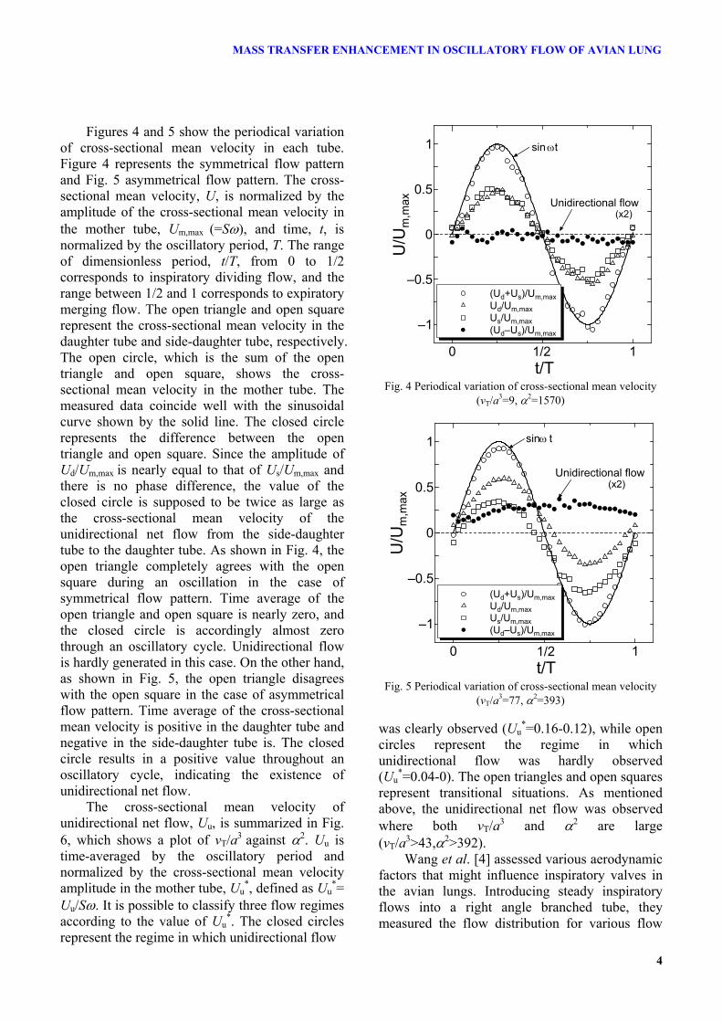
Figures 4 and 5 show the periodical variation of cross-sectional mean velocity in each tube. Figure 4 represents the symmetrical flow pattern and Fig. 5 asymmetrical flow pattern. The cross-sectional mean velocity, U, is normalized by the amplitude of the cross-sectional mean velocity in the mother tube, Um,max (=Sω), and time, t, is normalized by the oscillatory period, T. The range of dimensionless period, t/T, from 0 to 1/2 corresponds to inspiratory dividing flow, and the range between 1/2 and 1 corresponds to expiratory merging flow. The open triangle and open square represent the cross-sectional mean velocity in the daughter tube and side-daughter tube, respectively. The open circle, which is the sum of the open triangle and open square, shows the cross-sectional mean velocity in the mother tube. The measured data coincide well with the sinusoidal curve shown by the solid line. The closed circle represents the difference between the open triangle and open square. Since the amplitude of Ud/Um,max is nearly equal to that of Us/Um,max and there is no phase difference, the value of the closed circle is supposed to be twice as large as the cross-sectional mean velocity of the unidirectional net flow from the side-daughter tube to the daughter tube. As shown in Fig. 4, the open triangle completely agrees with the open square during an oscillation in the case of symmetrical flow pattern. Time average of the open triangle and open square is nearly zero, and the closed circle is accordingly almost zero through an oscillatory cycle. Unidirectional flow is hardly generated in this case. On the other hand, as shown in Fig. 5, the open triangle disagrees with the open square in the case of asymmetrical flow pattern. Time average of the cross-sectional mean velocity is positive in the daughter tube and negative in the side-daughter tube is. The closed circle results in a positive value throughout an oscillatory cycle, indicating the existence of unidirectional net flow.
The cross-sectional mean velocity of unidirectional net flow, Uu, is summarized in Fig. 6, which shows a plot of vT/a3 against α2. Uu is time-averaged by the oscillatory period and normalized by the cross-sectional mean velocity amplitude in the mother tube, Uu
*, defined as Uu*=
Uu/Sω. It is possible to classify three flow regimes according to the value of Uu
*. The closed circles represent the regime in which unidirectional flow
0 0.5 1
–1
–0.5
0
0.5
1
t/T
U/U
m,m
ax
(Ud+Us)/Um,maxUd/Um,maxUs/Um,max(Ud–Us)/Um,max
sin t
Unidirectional flow(x2)
ω
1/2
Fig. 4 Periodical variation of cross-sectional mean velocity
(vT/a3=9, α2=1570)
0 0.5 1
–1
–0.5
0
0.5
1
t/T
U/U
m,m
ax
(Ud+Us)/Um,maxUd/Um,maxUs/Um,max(Ud–Us)/Um,max
sin t
Unidirectional flow(x2)
ω
1/2
Fig. 5 Periodical variation of cross-sectional mean velocity
(vT/a3=77, α2=393)
was clearly observed (Uu*=0.16-0.12), while open
circles represent the regime in which unidirectional flow was hardly observed (Uu
*=0.04-0). The open triangles and open squares represent transitional situations. As mentioned above, the unidirectional net flow was observed where both vT/a3 and α2 are large (vT/a3>43,α2>392).
Wang et al. [4] assessed various aerodynamic factors that might influence inspiratory valves in the avian lungs. Introducing steady inspiratory flows into a right angle branched tube, they measured the flow distribution for various flow
4

ISTP-16, 2005, PRAGUE 16TH INTERNATIONAL SYMPOSIUM ON TRANSPORT PHENOMENA
rate and gas density. Their results showed that the asymmetrical feature of flow distribution was strengthened with an increase in inspiratory flow rate and gas density. Their finding indicates that the magnitude of the unidirectional flow in the avian lung is strongly correlated with the Reynolds number of inspiratory flow. The dotted line in Fig. 6 is the constant Reynolds number line of Re=104 defined in terms of the amplitude of cross-sectional mean velocity in the mother tube as Re=Um,maxd/ν. If the flow unsteadiness has little influence on the unidirectional net flow generation, Uu
* should be constant on this line. It can be seen from Fig. 6 that flow
unsteadiness of avian respiration suppresses the generation of the unidirectional flow. On the line of Re=104, the magnitude of unidirectional net flow, Uu
*, decreases with increasing α2. The trend seems to represent the negative influences of flow unsteadiness on the generation of unidirectional flow.
Figure 7 shows the relationship between Uu*
and Re. Note that Uu* is well correlated with Re
for all conditions of vT/a3. For the case of vT/a3<43, Uu
* increases with increasing Re and vT/a3. When vT/a3 is larger than 43, the increasing characteristics of Uu
* depends only on Re. The result indicates that convective inertia force might affect the generation of unidirectional net flow.
0 1000 2000 3000
0
20
40
60
80
100
2
v T/a
3
Laminer
Turbulent
R =780
Re=Const.(=104)
Uu*=0.04–0Uu*=0.08–0.04Uu*=0.12–0.08Uu*=0.16–0.12Normal respirationPanting
δ
α
Fig. 6 Flow regime diagram based on Uu*
0 10000 20000 30000
0
0.05
0.1
0.15
ReU
u* (=
Uu/
Um
,max
)
vT/a3=77vT/a3=66vT/a3=54vT/a3=43vT/a3=32vT/a3=20vT/a3=9
Fig. 7 Relationship between Uu* and Re
2.5.2 Flow pattern near the bifurcation The oscillatory flow structures, in particular
the formation and growth of vortices near the bifurcation, were visualized and analyzed in order to clarify the generation mechanism of the unidirectional net flow. Figure 8 shows typical flow patterns of the polystyrene or aluminum spheres observed and measured on the common median plane of the bifurcation, that is the central plane containing the tube axes, in the case of vT/a3=77 and α2=393, where the unidirectional net flow was clearly observed (see Fig. 5).
The upper pictures show the streamlines of tracers at various phases during an oscillatory cycle, and the lower figures show the vector fields of flow velocity measured with PIV at the same phases. The dimensionless period, t/T, between 0 and 1/2 corresponds to the inspiratory dividing flow, while 1/2<t/T<1 corresponds to expiratory merging flow.
During the oscillatory flow, three vortices were mainly observed. The vortices are named as A, B, and C as shown in Fig. 8. Vortex A was observed at the entrance of the side-daughter tube during the inspiratory phase (1/8<t/T<3/8). Similar to the previous observation [8], inspiratory flow can be classified roughly into two flow regimes, namely, “wall layer” near the tube wall and “free stream region” near the tube axis. As shown in Fig. 8(b) and Fig. 8(c), fluid in free
5

MASS TRANSFER ENHANCEMENT IN OSCILLATORY FLOW OF AVIAN LUNG
stream region goes through the daughter tube. The fluid in wall layer near inner wall separates at the branching point to form anti-clockwise vortex A at the entrance of the side-daughter tube. Preventing the fluid in the mother tube to flow into the side-daughter tube, vortex A enhances the asymmetrical feature of flow distribution at the bifurcation. Due to the blockage by vortex A, the cross-sectional mean velocity in the side-daughter tube is smaller than that in the daughter tube during the inspiratory phase (see Fig. 5). Vortex A is thought to enhance the generation of the unidirectional net flow from the results in Figs. 5 and 8.
Vortex B was observed near the outer wall of the daughter tube around t/T=3/8. As shown in Fig. 8(d), flow in the wall layer near the outer wall separates just before the bifurcation, and the clockwise vortex B is formed at this region. Since the vortex is very small and weak, it has little
influence on the flow distribution at the bifurcation.
Vortex C, the largest vortex, was observed in the mother tube during the expiratory phase (5/8<t/T<1). As shown in Figs. 8(f), (g), and (h), flow from the side-daughter tube separates at the branching point, and forms the clockwise vortex C near the inner wall of the mother tube. This vortex prevents the fluid in the daughter tube to flow into the mother tube, and enhances the generation of unidirectional net flow.
Unidirectional net flow from the side-daughter tube to the daughter tube can be observed even in the phase of t/T=1/2, in which cross-sectional mean velocity in the mother tube becomes zero and only vortex B exists in the daughter tube (see Fig. 8(e)). The fact indicates that convective inertia should dominate the flow fields.
Sω
s
dm
Proximal wall Distal wall
Inner wall
Outer wallSω
s
dm
Separation point[Vortex A]
Sω
s
dm[Vortex A]
Sω
s
dm[Vortex A]
[Vortex B] (a) t/T=0 (b) t/T=1/8 (c) t/T=1/4 (d) t/T=3/8
Sω
s
dm
[Vortex B] Sω
s
dm [Vortex C]
Separation point
Sω
s
dm [Vortex C]
Sω
s
dm [Vortex C]
(e) t/T=1/2 (f) t/T=5/8 (g) t/T=3/4 (h) t/T=7/8
Fig. 8 Flow pattern observed and measured on the common median plane of bifurcation (vT/a3=77, α2=393)
6

MASS TRANSFER ENHANCEMENT IN OSCILLATORY FLOW OF AVIAN LUNG
Sω
s
dm
( i )
Outer wall
Inner wall
Proximal wall Distal wall
[Vortex A]
Sω
s
dm
( i )
[Vortex A]
Sω
s
dm
( i )
[Vortex A]
Sω
s
dm
( i )
[Vortex A]
Uu*=0.13 Uu
*=0.12 Uu*=0.07 Uu
*=0.01
Sω
s
dm
( ii )
[Vortex B] Sω
s
dm
( ii )
Sω
s
dm
( ii )
Sω
s
dm
( ii )
Uu*=0.13 Uu
*=0.12 Uu*=0.07 Uu
*=0.01
Sω
s
dm
( iii )
[Vortex C]
Sω
s
dm
( iii )
[Vortex C]
Sω
s
dm
( iii )
[Vortex C]
Sω
s
dm
( iii )
[Vortex C]
Uu*=0.13 Uu
*=0.12 Uu*=0.07 Uu
*=0.01
(a) vT/a3=77, α2=393, Uu*=0.13 (b) vT/a3=43, α2=785, Uu
*=0.12 (c) vT/a3=20, α2=1570, Uu*=0.07 (d) vT/a3=9, α2=3140 , Uu
*=0.01
Fig. 9 Comparison of separation vortices at the fixed Re of 104, (i): t/T=1/4, (ii): t/T=1/2, (iii): t/T=3/4
From the observation of the flow fields, separation vortices and convective inertia were found to dominate the flow fields in the conditions where the unidirectional net flow was clearly induced.
2.5.3 Comparison of vortices at the fixed Re Figure 9 shows velocity vector fields around
the bifurcation at the fixed Reynolds number of 104. The top figures, marked (i), correspond to the phase in which the magnitude of inspiratory flow is maximum (t/T=1/4). The center figures, marked (ii), show the results when the cross-sectional mean velocity in the mother tube is zero (t/T=1/2). Then the bottom figures, marked (iii), correspond to the phase in which the magnitude of expiratory flow is maximum (t/T=3/4). Vortices A, B, and C can be seen in the top figures, center figures, and bottom figures, respectively.
In general, the separation vortices form and grow in increasing vT/a3 and decreasing α2 at a fixed Re. Note that no significant vortex is found at the entrance of the side-daughter tube in the case of vT/a3=9, α2=3140 (see Fig. 9(d)). The most important point in Fig. 9 is that the conditions where vortex A is clearly observed corresponds well to the conditions where the unidirectional net flow is clearly observed. From the result, a strong correlation is suggested between the formation of
vortex A and the generation of the unidirectional net flow. The decrease in unidirectional flow velocity with increasing oscillation frequency appeared in Fig. 6 might come from absence of vortices near the bifurcation, particularly absence of vortex A at the entrance of the side-daughter tube during inspriration.
3. Computational analysis 3.1 Computational method
Numerical simulations were performed to obtain the detailed views of the oscillatory flow fields. The generation mechanism and mass transport enhancement of the unidirectional net flow were studied from the results. Figure 10 shows schematic diagram of the computational domain. Every eight grid-points are shown in the figure. Similar to the experiment, a right angle branched tube was adopted as a model avian bifurcation. The computational domain was divided into two zones as shown in Fig. 10. Zone 1 consists of the mother tube and daughter tube, while zone2 covers the side-daughter tube. At the interface of the two zones, the grid points are overlapped to preserve numerical accuracy. The total number of grid points is approximately 210,000.

MASS TRANSFER ENHANCEMENT IN OSCILLATORY FLOW OF AVIAN LUNG
The diameter of each tube is 50mm, and the length is 300mm. Since the daughter tube and side-daughter tube were shorter than those in experimental model, the magnitude of unidirectional net flow, Uu
*, observed in the computation was stronger at the same flow conditions. The purpose of the present computation is to qualitatively analyze how the unidirectional net flow is generated, and how it enhances the gas transport.
The inlet boundary of the mother tube was assumed to be a piston surface. On the rigid walls, the no-slip condition was imposed. At the outlet boundary of the daughter tube and side-daughter tube, pressure was set to be zero and velocity was calculated by zero-order extrapolation. These outlet boundary conditions simulated reservoirs and a connecting tube of the experimental apparatus in Fig. 2.
For the flow simulation, the three-dimensional incompressible Navier-Stokes equations were solved by the SIMPLE method [9]. The working fluid was assumed to be water. Based on the flow results, the concentration field was analyzed through simulation of the diffusion of ink mixed into the water. The ink was assumed to have the same property as that of water. Mass fraction of the ink in the mixture is defined as the ink concentration C. After the computational flow field becomes periodic, the ink is supplied instantly at phase 0 from the entrance of the mother tube. The convection equation of C is solved by the cubic
Mother tube
Side-daughter tube
Daughter tubeProximal wall
Distal wall
Inner wall
Outer wall
Zone1 : 179 x 21 x 41Zone2 : 41 x 21 x 71
Zone2
Zone1
Fig. 10 Computational domain
interpolated propagation (CIP) method [10] to obtain the concentration field.From the fact that the partial pressure of oxygen in the inner part of avian lung is almost equal to that in the atmosphere [11], molecular diffusion was neglected in the present study. The courant number was kept less than 0.2 to treat the convection term explicitly.
3.2 Verification of developed code To verify the computational code, oscillatory
flow in a straight tube was solved. Figure 11 shows the periodical variation of radial velocity profiles at α2=40. The computational results show good agreement with theoretical predictions.
3.3 Flow pattern near the bifurcation The figures of branched tube shape in Fig. 12
show the variation of axial velocity profiles on the common median plane. The velocity vectors of secondary flow and axial velocity contours in the cross sections near the bifurcation are plotted in circular figures. The flow condition is vT/a3=50 and α2=40 in which the unidirectional net flow was clearly observed (Uu
*=0.18). To help our understanding, contour field of
vorticity at the phase of t/T=1/2 is also shown in Fig. 12(a’). It is evident that vortex A exists at the entrance of the side-daughter tube.
–1 –0.5 0 0.5 1–1.5
–1
–0.5
0
0.5
1
1.5
r/a
u/S
ComputationTheory
t/T=0
t/T=1/12
t/T=1/6
t/T=1/4
t/T=3/4t/T=10/12
t/T=11/12
ωω
Fig. 11 Radial velocity profiles (α2=40)
8

MASS TRANSFER ENHANCEMENT IN OSCILLATORY FLOW OF AVIAN LUNG
u/Um,max
u/Um,max=1.0
=1.0
vortex Am
s
d
(a) t/T=1/4
s
m d
(a’) t/T=1/4 (contour field of vorticity) Distorted profiles of axial velocity in the
branched tubes in Fig.12 indicate the presence of separation vortices. Since the flow condition of the computation is not completely identical to that of the experiment shown in Fig. 8, direct comparison between Fig. 12 and Fig. 8 is difficult. Nevertheless, Fig. 12 shows the similar trend to Fig. 8, and the three vortices, vortex A, B and C, can be seen in the branched tubes of Fig. 12.
In Fig. 12(a), vortex A is observed at the entrance of the side-daughter tube during inspiratory phase of t/T between 1/9 and 5/12.
u/Um,max
u/Um,max=1.0
=1.0vortex B
m
s
d
(b) t/T=1/2
u/Um,max
u/Um,max=1.0
=1.0
vortex Cm
s
d
(c) t/T=3/4 Fig. 12 Axial velocity profiles on the common median plane and secondary flow (vT/a3=50, α2=40)
Vortex B is observed near the outer wall of the daughter tube during 5/12<t/T<1/2, though it is rather difficult to see in Fig. 12(b). And as seen in Fig. 12(c), vortex C is observed near the inner wall of the mother tube during expiratory phase of 7/12<t/T<1. These trends are closely correspondent with the experimental results.
In the circular figures of Figs. 12(a) and 12(c), secondary flow can be seen in the side-daughter tube during the inspiratory phase and in mother
9

MASS TRANSFER ENHANCEMENT IN OSCILLATORY FLOW OF AVIAN LUNG
tube during expiratory phase. As observed in the figures of branched tube, the axial velocity profiles near the bifurcation are distorted and contain high velocity ridge while those near the tube ends show uniform profiles. This is because the secondary flow mixes the high velocity flow with the reverse flow in the separation vortices across the tube cross-section.
Although studying the detailed structures of the secondary flow is important and very interesting thing itself, the main concern of this study is the generation mechanism of the unidirectional flow observed in avian trachea, thus detailed view of the secondary flow is not mentioned here. The formation of the secondary flow might not have direct and strong correlation with the generation of the unidirectional net flow, because the unidirectional net flow is observed even in the two-dimensional simulation in which no secondary flow is generated.
3.4 Unidirectional flow and pressure drop Figure 13 shows the periodical variation of
cross-sectional mean velocity in each tube at vT/a3=50, α2=40. The cross-sectional mean velocity, U, is normalized by the amplitude of cross-sectional mean velocity in the mother tube, Um,max. In Fig.13, the cross-sectional mean velocity of unidirectional net flow, Uu
*, gradually decreases with time, and sharply rises around t/T=1/8, followed by gradual decrease. The phase of the sharp rise in Uu
* corresponds to the phase in which vortex A begins to grow.
Figure 14 shows the periodical variation of pressure difference between the entrance of the daughter tube and side-daughter tube, pd-ps. The pressure difference is normalized by the dynamic pressure defined in terms of the amplitude of cross-sectional mean velocity in the mother tube and fluid density, 0.5ρUm,max
2. Since the pressure is calculated by extrapolating two data near the end of each tube, pressure difference pd-ps is interpreted to roughly represent the averaged pressure drop caused by separation vortices near the bifurcation. Two peaks are observed in the results of Fig.14. The first higher peak around t/T=1/4 is attributed to vortex A, while the second lower peak around t/T=3/4 seems to be attributed to vortex C.
In Figs.13 and 14, the waveform of Uu* is
observed to have similar trend to that of pd-ps. It is
thus evident that pressure drop caused by separation vortices (particularly vortex A) plays an important role in the generation of the unidirectional net flow. Despite of the similarity, there exist some differences between the waveforms of Uu
* and pd-ps. For example, pd-ps increases and decreases abruptly while Uu
*
gradually and there is a phase lag between the waveform of pd-ps and that of Uu
*. The difference raises a question for the reason why Uu
* persists even in t/T=1/2 when no large vortex exists near the bifurcation and pressure difference pd-ps is nearly zero. The answer to this question requires further consideration of the generation mechanism of the unidirectional net flow.
0 0.5 1–1
–0.5
0
0.5
1
Um/Um,maxUd/Um,maxUs/Um,max(Ud–Us)/Um,max
1/2
Eq. (1) (x2)
Unidirectional flow(x2)
(Ud+Us)/Um,max
t/T
U/U
m,m
ax
(Ud-Us)/Um,max=2Uu*
Fig. 13 Periodical variation of cross-sectional mean velocity (vT/a3=50, α2=40)
0 0.5 1
0
0.2
0.4
0.6
t/T
(pd–
p s)/
Um
,max
ρ2
1/2
m d
s
pspd
(pd-
p s)/0
.5ρU
m,m
ax2
Fig. 14 Periodical variation of pressure difference, pd-ps
(vT/a3=50, α2=40)
10

MASS TRANSFER ENHANCEMENT IN OSCILLATORY FLOW OF AVIAN LUNG
Consider now the one-dimensional momentum equation of the unidirectional net flow in the control volume of the daughter tube and side-daughter tube. The momentum equation is simply ∂(ρUu)/ ∂t·(2L – d) = pd - ps - R ·Uu (1)
where ρ is fluid density and R is resistive impedance of the daughter tube and side-daughter tube. The left hand side of Eq. (1) expresses the unsteady term while the right hand side represents the pressure term and viscous term. The resistance R can be estimated based on the Poiseuille’s law (R=8µ(2L-d)/πa3, where µ is fluid viscosity), because radial velocity profile of the unidirectional net flow is parabolic in the case of vT/a3=50, α2=40. The pressure term is estimated by pressure difference pd-ps obtained in the computation, which is plotted as the open circle in Fig. 14.
The broken line in Fig. 13 represents the value twice as large as the cross-sectional mean velocity of the unidirectional net flow calculated by Eq. (1). The calculated result is in good agreement with the numerical result of Uu
*. If the unsteady term of Eq.
(1) was neglected, the waveform of Uu* should be
identical to that of pd-ps. Hence, the differences between the waveforms of Uu
* and pd-ps seems to come from the convective inertia of unidirectional net flow, which becomes visible by considering the unsteady term of Eq. (1).
In summery, the generation mechanism of the unidirectional net flow can be explained as follows: first, unidirectional net flow begins to grow by the pressure drop caused by a separation vortex at the entrance of the side-daughter tube (vortex A) during the inspiratory phase (0<t/T<1/2). Once the unidirectional net flow is generated, it persists even in the phase of t/T=1/2 in which no vortex exists near the bifurcation. The persistent characteristics come from the convective inertia. Vortex C prevents the fluid in the daughter tube to flow into the mother tube, thereby enhances the unidirectional net flow during the expiratory phase (1/2<t/T<1).
(a)t/T=1/4 (b)t/T=2/4 (c)t/T=3/4 (d)t/T=4/4
Fig. 15 Visualization of fresh gas inspired from the mother tube (i): vT/a3=50, α2=2, Uu
*=0.01, (ii): vT/a3=50, α2=8, Uu*=0.05, (iii): vT/a3=50, α2=40, Uu
*=0.18
11

MASS TRANSFER ENHANCEMENT IN OSCILLATORY FLOW OF AVIAN LUNG
3.5 Enhancement of axial gas transport Due to the unidirectional flow, gas exchange
efficiency of avian lungs is much higher than that of mammalian lungs [3]. Although the fact is well known, the specific mechanisms how the unidirectional flow enhances gas transport have received much less attention. The objective of this section is to analyze mass transport mechanisms by the unidirectional flow. The fresh gas inspired from the mother tube was visualized during oscillatory cycles for the purpose.
Figure 15 shows the movement of fresh gas inspired from the entrance of the mother tube. The top figures, (i), correspond to the condition where the unidirectional net flow is hardly generated (vT/a3=50, α2=2, Uu
*=0.01). The center figures, (ii), show the results when the unidirectional net flow is slightly generated (vT/a3=50, α2=8, Uu
*=0.05). Then the bottom figures, (iii), represent the results for the case where the unidirectional net flow is clearly generated (vT/a3=50, α2=40, Uu
*=0.18). Numerical simulations were performed under the fixed value of vT/a3 = 50.
In all cases, the fresh gas inspired from the entrance of the mother tube goes through the daughter tube during the inspiratory phase (0<t/T<1/2). In the case of vT/a3=50, α2=2, (i), the inspired fresh gas goes back to the entrance of the mother tube during the expiratory phase (1/2<t/T<1), since the flow in the daughter tube is purely oscillatory. Hence, almost all gas inspired from the mother tube dose not contribute to gas exchange.
On the contrary in the case of vT/a3=50 and α2=40, (iii), the amplitude of inspiratory flow is greater than that of expiratory flow in the daughter tube. Fresh gas inspired from the mother tube is trapped and remains in the daughter tube during the expiratory phase. From the comparison
between the cases (i) and (iii), it is evident that the unidirectional net flow strongly enhances axial gas transport.
The transport efficiency is defined here as Gd,out/Gm,in, representing the volume rate of fresh gas expired from the end of the daughter tube, Gd,out, to the fresh gas inspired from the inlet of the mother tube, Gm,in, during an oscillatory cycle. Figure16 shows the dependence of Gd,out/Gm,in and Uu
* on Re. It is clearly shown that the gas transport efficiency increases with an increase of the magnitude of the unidirectional net flow. In the case of vT/a3=50 and α2=2 where the unidirectional net flow does not occur, only 1% of fresh gas is available for the gas exchange, while in the case of vT/a3=50 and α2=40 where the unidirectional net flow is clearly occurs, about 27% of fresh gas is available.
3.5 Effect of constriction Jones et al. [12] investigated the structure of
avian trachea by radiographic techniques. Their results indicated the presence of a constriction segment at the inlet of the bifurcation. Wang et al. [4] investigated the flow distribution of the steady inspitatory flow in a right angle branched tube with a constriction in the mother tube, assuming that the geometry of the mother tube might influence the velocity profile and the flow distribution at the bifurcation. Their results showed that the asymmetrical feature of the flow distribution was strongly enhanced by the constriction, resulting in the unidirectional flow. Since their study only dealt with inspiratory steady flow, the effect of constriction during oscillatory flow remains unclear. The oscillatory flow field in a right angle branched tube with a constriction in the mother tube was hence numerically studied.
0 200 400 6000
0.1
0.2
0.3
0
0.1
0.2
Re
Gd,
out/G
m,in
Uu *(=U
u /Um
,max )
Gd,out/Gm,inUu
*(=Uu/Um,max )
Fig. 16 Enhancement of axial gas transport by unidirectional net flow

MASS TRANSFER ENHANCEMENT IN OSCILLATORY FLOW OF AVIAN LUNG
dθ
Constrictionm sd
d
θ
d c
Lc
Fig. 17 Schematic view of constriction
Figure 17 shows schematic view of the
constriction part of the test tube. As the constriction, the diameter of mother tube is designed to be 40mm (dc/d=4/5) in the range from 50mm to 250mm upstream of the side-daughter tube axis (Lc=200mm). To suppress the flow separation, the constriction has 30 degrees tapers, (θ), at both ends.
Figure 18 shows periodical variation of the cross-sectional mean velocity in each tube for the case of vT/a3=50 and α2=40. The broken line represents the result without constriction identical to the closed circles in Fig. 13. It is evident that the magnitude of unidirectional net flow is clearly enhanced by the constriction through an oscillatory cycle. In other words, the constriction strongly enhances the asymmetrical feature of flow distribution.
Figure 19 shows the variation of the axial velocity profiles, velocity vectors of secondary flow, and axial velocity contours in the cross-sections near the bifurcation at vT/a3=50 and α2=40. Since the constriction accelerates the inspiratory flow, axial velocity profile before the bifurcation is strongly influenced and has a high velocity peak around the tube axis. Due to the sharp profile of axial velocity, fluid in the mother tube tends to go straight rather than turns the corner. In this way asymmetrical feature of flow distribution is strongly enhanced by the constriction, resulting in the enhancement of the unidirectional net flow magnitude. The sharp profile also encourages the formation of vortex A that was found to be a principle mechanism of the unidirectional net flow. Namely, the enhancement mechanism of the unidirectional net flow magnitude could be attributed to a sharp profile of inspiratory flow just before the bifurcation.
0 0.5 1–1
–0.5
0
0.5
1
Um/Um,maxUd/Um,maxUs/Um,max(Ud–Us)/Um,max
1/2
Unidirectional flow(x2)
t/T
U/U
m,m
ax
(Ud+Us)/Um,max
W/ constriction
W/o constriction
Fig. 18 Periodical variation of cross-sectional mean velocity
(vT/a3=50, α2=40)
The effect of the constriction on the magnitude of the unidirectional net flow, Uu
*, is summarized in Fig. 20. The constriction just upstream of the bifurcation is seen to enhance the magnitude of the unidirectional net flow in all cases. In the range of 0<Re<1000, the magnitude of unidirectional net flow with the constriction shown by the closed circles becomes about 1.5 times larger than that without the constriction.
u/Um,max
u/Um,max =1.0
=1.0
m d
s
vortex AConstriction
(a) t/T=1/4

MASS TRANSFER ENHANCEMENT IN OSCILLATORY FLOW OF AVIAN LUNG
u/Um,max
u/Um,max =1.0
=1.0
m d
s
vortex B
(b) t/T=1/2
u/Um,max
u/Um,max =1.0
=1.0
m d
s
vortex C
(c) t/T=3/4
Fig. 19 Axial velocity profiles on the common median plane and secondary flow with constriction (vT/a3=50, α2=40)
4. Conclusions To clarify the flow phenomena in the avian
lung trachea, oscillatory flow in a right angle branched tube was experimentally and numerically studied. The conclusions are summarized as follows
1. Unidirectional net flow is generated from the side-daughter tube to the daughter tube when both dimensionless tidal volume and dimensionless frequency are large.
2. Pressure drop caused by the separation vortex at the entrance of the side-daughter tube drives the unidirectional net flow. Due to convective inertia, the unidirectional net flow persists in the expiratory phase in which no large vortex exits near the bifurcation.
3. The unidirectional net flow strongly enhances the axial mass transport in the process of avian respiration. In the present cases, the axial mass transport with the unidirectional net flow is enhanced with increase in the magnitude of unidirectional net flow.
4. Constriction just upstream of the bifurcation increases the magnitude of unidirectional net flow.
Acknowledgement
The present work was supported in part by the Ministry of Education, Culture, Sports, Science and Technology through the 21st century COE Program, “Mechanical Systems Innovation.”
200 400 600 8000
0.1
0.2
0.3
dc/d=1.0dc/d=0.8
Re
Uu* (=
Uu/
Um
,max
)
Fig. 20 Enhancement of the magnitude of unidirectional net flow by constriction
14

MASS TRANSFER ENHANCEMENT IN OSCILLATORY FLOW OF AVIAN LUNG
Reference [1] Butler J P, Banzett R B and Fredberg J J. Inspiratory
valving in avian bronchi: aerodynamic considerations. Respir. Physiol. 72, pp 241-256, 1988.
[2] King A S. Structural and functional aspects of the avian lung and air sacs. Int. Rev. Gen. Exp. Zool., 2, pp 171-267, 1966.
[3] Calder W A and Nielsen K S. Panting and blood carbon dioxide in birds. American Journal of Physiology, 215, pp 477-482, 1968.
[4] Wang N, Banzett R B, Butler J P and Fredberg J J. Bird lung models show that convective inertia effects inspiratory aerodynamic valving. Respir. Physiol., 73, pp 111-124, 1988.
[5] Ohmi M, Iguchi M and Urahara I. An experimental study of velocity distribution and inlet length in the inlet region of laminar oscillatory pipe flow, Trans. JSME (in Japanese), 52B, pp 2518-2525, 1986.
[6] Jan D L, Shapiro A H and Kamm R D. Some features of oscillatory flow in a model bifurcation, J. Appl. Physiol., 67, pp 147-159, 1989.
[7] Hino M, Sawamoto M and Takasu S. Experiments on transition to turbulence in an oscillatory pipe flow. J. Fluid. Mech., 75, pp 193-207, 1976.
[8] Alfred C P and Ostrach S. Blood flow in bronching vessels. J. Appl. Physiol., 41, 5, pp646-658, 1976.
[9] Patankar S V. Numerical Heat Transfer Fluid Flow, Hemisphere, 1980.
[10] Yabe T and Aoki T. Two and three dimensional solvers, Compt. Phys. Commun., 66, pp 233-242, 1991.
[11] Yamada Y, Tanishita K, Tanasawa I and Yokoyama S, Science of body, heat and flow (in Japanese), ohmsha, 1998.
[12] Jones J H, Effmann E L and Nielsen K S. Control of air flow in bird lungs: radiographic studies. Respir. Physiol., 45, pp 121-131, 1981.