mass timber floor vibration€¦ · mass timber floor vibration adam gerber, m.a.sc....
TRANSCRIPT

Mass Timber Floor Vibration
Adam Gerber, M.A.Sc.
Disclaimer: This presentation was developed by a third partyand is not funded by WoodWorks or the Softwood Lumber Board.

“The Wood Products Council” is a Registered Provider with The American Institute of Architects Continuing Education Systems (AIA/CES), Provider #G516.
Credit(s) earned on completion of this course will be reported to AIA CES for AIA members. Certificates of Completion for both AIA members and non-AIA members are available upon request.
This course is registered with AIA CES for continuing professional education. As such, it does not include content that may be deemed or construed to be an approval or endorsement by the AIA of any material of construction or any method or manner ofhandling, using, distributing, or dealing in any material or product.___________________________________________
Questions related to specific materials, methods, and services will be addressed at the conclusion of this presentation.

Course Description
While the ‘look’ of a building gets most of the attention, effective detailing has just as much impact on client satisfaction over the long term. This workshop brings together three experts to discuss areas of multi-family and commercial wood design where effective detailing techniques can improve performance and mitigate occupant complaints. First, a WoodWorks expert will discuss best practices for accommodating wood shrinkage with a focus on effective detailing at wood framing to finish interfaces. An acoustics expert will then discuss acoustical design in light-frame wood structures, with a focus on assembly options, detailing techniques, material selection and proper installation. Finally, a structural engineer with expertise in wood design will examine floor vibration design parameters and strategies that result in effective mass timber floor systems.

Learning Objectives
• 1. Provide basic understanding of structural dynamic properties of floors and key influencing parameters.
• 2. Be able to identify vibration prone structural configurations and details
• 3. Become familiar with analysis techniques and acceptance criteria for vibration performance of floors
• 4. Awareness of mitigation techniques and analysis “tips & tricks”

Agenda
1. Introduction to Floor Vibrations
2. Dynamic Characteristics of Conventional Framed Systems
3. Mass Timber Floors With Examples
4. Design & Analysis Suggestions

4 Things to remember
1. You can’t have your cake and eat it too, if mass is there, you have to consider it.
2. Stiffness and mass are represented by the frequency.
3. Inherent damping is free, supplemental damping is expensive!
4. Every person will experience and judge a floor’s performance differently!

1. Floor Vibrations


1.1 Sources of Vibration
• Human activity (eg. walking, jumping, dancing, etc.)
• Vibrating machinery (air conditioners, fans, etc.)
• External forces (eg. traffic, wind buffeting)

1.2 Top Complaints
• “Bouncy” floors
• Dishes rattling on hard surfaces
• Floors that squeak
• Sensitive equipment doesn’t operate correctly

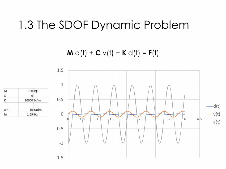
1.3 The SDOF Dynamic Problem
M a(t) + C v(t) + K d(t) = F(t)

1.3 The SDOF Dynamic Problem
M a(t) + C v(t) + K d(t) = F(t)
M - Mass à slugs [kg]
C – Viscous Damping Coefficient à lb*s/in [N*s/m]
K – Spring Stiffness à lb/in [N/m]
F – Forcing Function à lb [N]

1.3 The SDOF Dynamic Problem
M a(t) + C v(t) + K d(t) = F(t)
!" = %& à rad/s
'" =()*+ = %&à Hz
,(.) = 01234(!t) à lb [N]
1.3 The SDOF Dynamic Problem
M a(t) + C v(t) + K d(t) = F(t)
-1.5
-1
-0.5
0
0.5
1
1.5
0 0.5 1 1.5 2 2.5 3 3.5 4 4.5
d(t)v(t)a(t)

1.4 The MDOF Dynamic Problem
[M] a(t) + [C] v(t) + [K] d(t) = [F](t)
[M] - Mass Matrix à slugs [kg]
[C] – Damping Matrix à lb*s/in [N*s/m]
[K] – Stiffness Matrix à lb/in [N/m]
[F] – Loading Matrix à lb [N]

1.4 The MDOF Dynamic Problem
[K] – Stiffness Matrix à lb/in [N/m]
…

1.5 Modal Analysis For Floor Vibrations
CCIP-016 (2006)

1.5 Modal Analysis For Floor Vibrations
CCIP-016 (2006)

1.5 Modal Analysis For Floor Vibrations
CCIP-016 (2006)
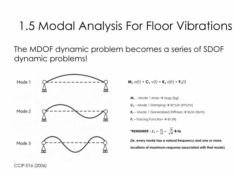
The MDOF dynamic problem becomes a series of SDOF dynamic problems!
M a(t) + C v(t) + K d(t) = F(t)
M - Modal Mass à slugs [kg]
C – Modal Damping à lb*s/in [N*s/m]
K – Generalized Stiffness à lb/in [N/m]
F – Forcing Function à lb [N]
1.5 Modal Analysis For Floor Vibrations
CCIP-016 (2006)
The MDOF dynamic problem becomes a series of SDOF dynamic problems!
M1 a(t) + C1 v(t) + K1 d(t) = F1(t)
M1 - Mode 1 Mass à slugs [kg]
C1 – Mode 1 Damping à lb*s/in [N*s/m]
K1 – Mode 1 Generalized Stiffness à lb/in [N/m]
F1 – Forcing Function à lb [N]
*REMEMBER - !" = %"&' = ()à Hz
(ie. every mode has a natural frequency and one or more
locations of maximum response associated with that mode)
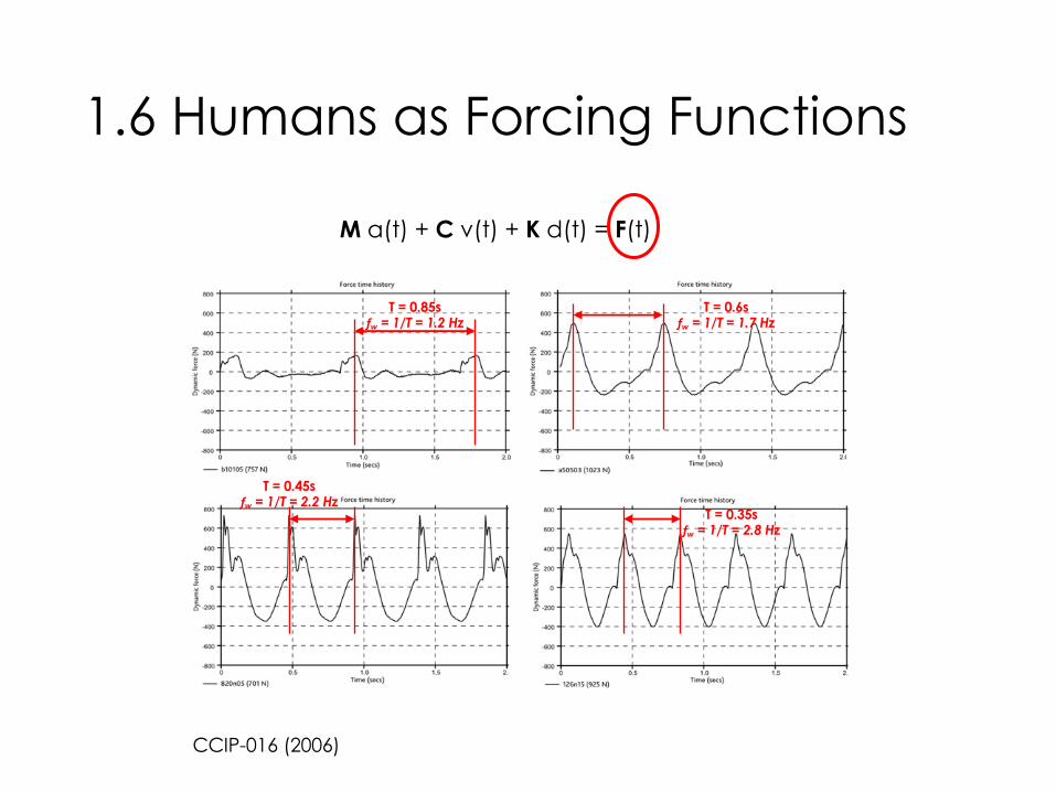
1.6 Humans as Forcing Functions
CCIP-016 (2006)
M a(t) + C v(t) + K d(t) = F(t)
T = 0.6sfw = 1/T = 1.7 Hz
T = 0.35sfw = 1/T = 2.8 Hz
T = 0.85sfw = 1/T = 1.2 Hz
T = 0.45sfw = 1/T = 2.2 Hz
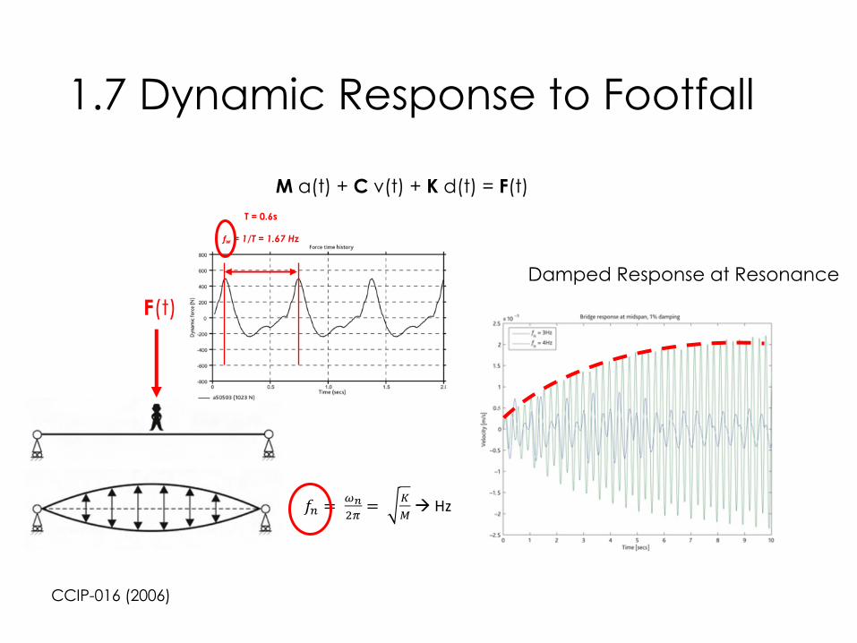
1.7 Dynamic Response to Footfall
CCIP-016 (2006)
M a(t) + C v(t) + K d(t) = F(t)T = 0.6s
fw = 1/T = 1.67 Hz
!" = %&'( = )*à Hz
Damped Response at Resonance
F(t)

1.7 Dynamic Response to Footfall
CCIP-016 (2006)
M a(t) + C v(t) + K d(t) = F(t)
Damped Response at ResonanceFrequency Response Function (FRF)

1.7 Dynamic Response to Footfall
CCIP-016 (2006)
Frequency Response Function (FRF)!"#$→& = "∗*+ *,- à frequency ratio for first four harmonics of first mode.
Does mode 1 have a natural frequency that matches a harmonic of the possible walking frequencies?
Example:
.$ = 601
1.501 ≤ .6 ≤ 2.501
1st Harmonic
2nd Harmonic3rd Harmonic
4th Harmonic
Harmonic Range of i*fwMatched fw ri
I = 1 1.501 ≤ 1 ∗ .6 ≤ 2.501 1*1.5 = 1.5 Hz 4.0
I = 2 3.001 ≤ 2 ∗ .6 ≤ 5.001 2*1.5 = 3.0 Hz 4.0
I = 3 4.501 ≤ 3 ∗ .6 ≤ 7.501 3*2.0 = 6.0 Hz 3.0
I = 4 6.001 ≤ 4 ∗ .6 ≤ 1001 4*1.5 = 6.0 Hz 4.0

1.8 Human Perception
SCI-P354 (2010)

1.8 Human Perception
AISC Design Guide 11 (2016)
-1.5
-1
-0.5
0
0.5
1
1.5
0 0.5 1 1.5 2 2.5 3 3.5 4 4.5
a(t)
RMS

1.8 Human Perception
AISC Design Guide 11 (2016)

1.8 Human Perception
AISC Design Guide 11 (2016)

1.8 Acceptance Criteria
AISC Design Guide 11 (2016)

2. Dynamic Properties of Framing Systems

2.1 CIP Concrete StructuresMass
• 100 – 150 psf floor weight [heavy]
Damping
• 1-5% of critical
Stiffness
• Ec_dynamic = 1.35*Ec
• 2-way action
General Observations:
• High dead load has favorable effect of reducing accelerations W∝ $%& but unfavorable effect of lowering
fundamental frequency '( ∝ $)
• Damping in similar range to other construction types.
• Increased dynamic modulus of concrete has favorable effect of reducing accelerations '( ∝ *
• Not typically prone to complaints of disturbing floor vibrations

2.2 Steel & Composite StructuresMass
• 50 – 100 psf floor weight [moderate]
Damping
• 0.5-5% of critical
Stiffness
• Ec_dynamic = 1.35*Ec
• Depends on framing sizes and layout
General Observations:
• Dead load has favorable effect of reducing accelerations W ∝ $%& but unfavorable effect of lowering fundamental
frequency '( ∝ $) . The governing requirements (more or less weight) depends on '(.
• Ranges from very lightly damped (high probability of resonance) to moderately damped
• Increased dynamic modulus of concrete has favorable effect of reducing accelerations '( ∝ +
• ,-.= ,
-0+ ,
-2à -. ≤ -2 à flexibility in the system (eg. girders vs. walls) ALWAYS reduces your fundamental frequency!
• Vibration problems in light weight composite structures are generally well understood and designed for.
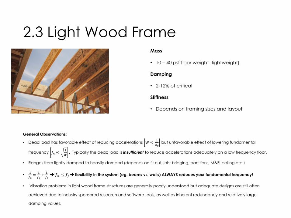
2.3 Light Wood FrameMass
• 10 – 40 psf floor weight [lightweight]
Damping
• 2-12% of critical
Stiffness
• Depends on framing sizes and layout
General Observations:
• Dead load has favorable effect of reducing accelerations W ∝ $%& but unfavorable effect of lowering fundamental
frequency '( ∝ $) . Typically the dead load is insufficient to reduce accelerations adequately on a low frequency floor.
• Ranges from lightly damped to heavily damped (depends on fit out, joist bridging, partitions, M&E, ceiling etc.)
• +,-= +
,/+ +
,1à ,- ≤ ,1 à flexibility in the system (eg. beams vs. walls) ALWAYS reduces your fundamental frequency!
• Vibration problems in light wood frame structures are generally poorly understood but adequate designs are still often
achieved due to industry sponsored research and software tools, as well as inherent redundancy and relatively large
damping values.

2.4 Mass Timber & Hybrid Systems
Typical Mass Timber Materials:
• Cross Laminated Timber
• Nail/Dowel Laminated Timber
• Glue-laminated Timber
• Mass Plywood Panels
• Mass LSL panels

2.4 Mass Timber & Hybrid SystemsMass
• 15 – 65 psf floor weight [lightweight…ish]
Damping
• 1-6% of critical
Stiffness
• Depends on framing sizes and layout
General Observations:
• Dead load has favorable effect of reducing accelerations W ∝ $%& but unfavorable effect of lowering fundamental frequency
'( ∝ $) . At low end, dead load is insufficient, however at high end of range, may be sufficient to reduce accelerations on a low
frequency floor.
• Ranges from lightly damped to moderately damped (depends on fit out, M&E, support conditions, partitions, etc.)
• +,-= +
,/+ +
,1à ,- ≤ ,1 à flexibility in the system (eg. beams vs. walls) ALWAYS reduces your fundamental frequency!
• There is general awareness of vibration problems in mass timber structures, but little direct guidance.
• CLT Design Guide, FPInnovations/CSA-086 formulae inadequate to address range of design scenarios and are potentially misleading
regarding their scope of application.

3. Mass Timber Vibration Design

3.1 MT Panels on MT WallsTypical Design Process
Span: 20’
D: 40 psf (self-weight + topping)
SDL: 20 psf (partition load)
L: 40 psf
1.2D + 1.6L = 136 psf
Deflection Limits:
∆""= ∆$%≤ "
()*= 1/2" → 01233_567 =
89":
;)(∆<<= 2.88?10)AB ∗ DEF/GH
∆%= IJ5 ∗ ∆"% + ∆$%≤ L
240= 1" → 01233_567 =
5OL(
384∆%= 576?10SAB ∗ DEF/GH
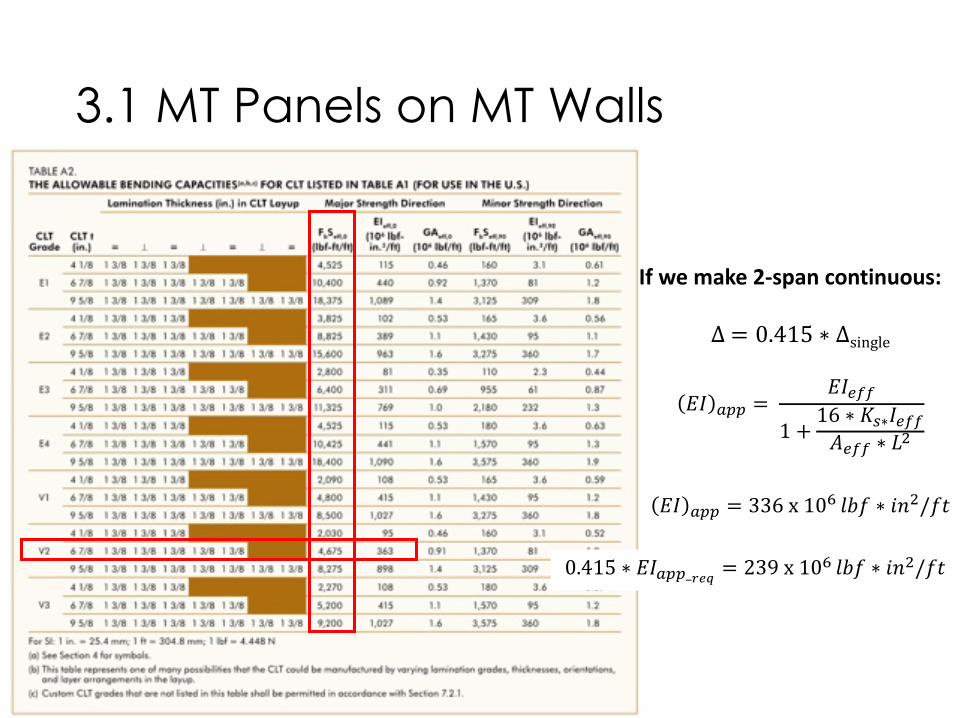
3.1 MT Panels on MT Walls
If we make 2-span continuous:
∆= 0.415 ∗ ∆single
01 233 = 01455
1 +16 ∗ 89∗1455:455 ∗ ;<
01 233 = 336x10?@AB ∗ CD</BF
0.415 ∗ 01233_HIJ = 239x10?@AB ∗ CD</BF

3.1 MT Panels on MT WallsTypical Design Process
Span: 20’
D: 40 psf (self-weight + topping)
SDL: 20 psf (partition load)
L: 40 psf
1.2D + 1.6L = 136 psf
Deflection Limits:
∆""= ∆$%≤ "
()*= 1/2" → 01233_567 =
89":
;)(∆<<= 2.88?10)AB ∗ DEF/GH
∆%= IJ5 ∗ ∆"% + ∆$%≤ L
240= 1" → 01233_567 =
5OL(
384∆%= 576?10SAB ∗ DEF/GH
0.415 ∗ 01233TUV = 356x10SABG ∗ DEF/GH

3.1 MT Panels on MT WallsTypical Design Process
Span: 20’
D: 40 psf (self-weight + topping)
SDL: 20 psf (partition load)
L: 40 psf
1.2D + 1.6L = 136 psf
Strength Requirements:
!" = $%&'( = 6800-. ∗ "0/"0
2" = 1.25 ∗ 7" ∗ 8 = 1700-."/"0

3.1 MT Panels on MT Walls
!" #$%% = 4675,-. ∗ .0/.0

3.1 MT Panels on MT WallsTypical Design Process
Span: 20’
D: 40 psf (self-weight + topping)
SDL: 20 psf (partition load)
L: 40 psf
1.2D + 1.6L = 136 psf
Strength Requirements (NDS 2015):
!" = 6800()" ∗ "+/"+ -. /0112= -. /011 ∗ 34 ∗ 35 ∗ 36 ∗ 2.54 ∗ 0.85 ∗ λ = <=>?@AB ∗ BC/BC
D" = 1700()"/"+ -G ∗ H∗.IJ 011
2= -G ∗ H∗.
IJ 011∗ 34 ∗ 35 ∗ 2.88 ∗ 0.75 = ?KLM@AB/BC
34= 35= 36=1.0 λ = 0.8

3.1 MT Panels on MT WallsTypical Design Process
Span: 20’
D: 40 psf (self-weight + topping)
SDL: 20 psf (partition load)
L: 40 psf
1.2D + 1.6L = 136 psf
Verify Vibration Performance:
???

3.1 MT Panels on MT WallsTypical Design Process
Span: 20’
D: 40 psf (self-weight + topping)
SDL: 20 psf (partition load)
L: 40 psf
1.2D + 1.6L = 136 psf
Verify Vibration Performance:
1. Consult Manufacturer’s Literature


3.1 MT Panels on MT WallsVerify Vibration Performance:
1. Consult Manufacturer’s Literature

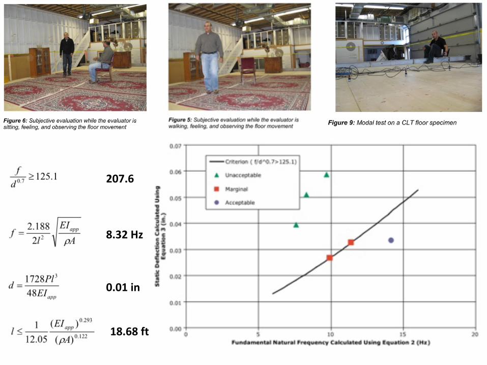
8.32 Hz
0.01 in
18.68 ft
207.6

Limitations of the Simplified Method:
1. Bare floors with finishing, partitions and furniture, but without heavy topping.
2. Vibrations are induced by normal walking
3. Well supported floors**
4. Well-jointed CLT panels
5. Inclusion of the self-weight of CLT panels only (ie. without live load)
Vibration Controlled Span for our Design Scenario:
! ≤ 18.7()(US CLT Handbook)
! ≤ 17.5()(CSA 086-14 permits 20% increase for continuous span à + ≤ ,-./)
! ≤ 16.8()(Manufacturer’s literature implies > 20ft for double span)

3.2 Post & Beam ConfigurationsTypical Design Process
Span: 20’ x 30’ grid
D: 40 psf (self-weight + topping)
SDL: 20 psf (partition load)
L: 40 psf
1.2D + 1.6L = 136 psf
Deflection Limits For Beams:
∆""= ∆$%≤ "()*
= 3/4" → 01234 = 56"7
8)(∆99= 1.94=10?*@A ∗ CDE
∆%= FG2 ∗ ∆"% + ∆$%≤ I240
= 1.5" → 01234 = 5LI(
384∆%= 3.88=10?*@A ∗ CDE
Try 8.5” x 31.5” 24f-1.8E Glulam
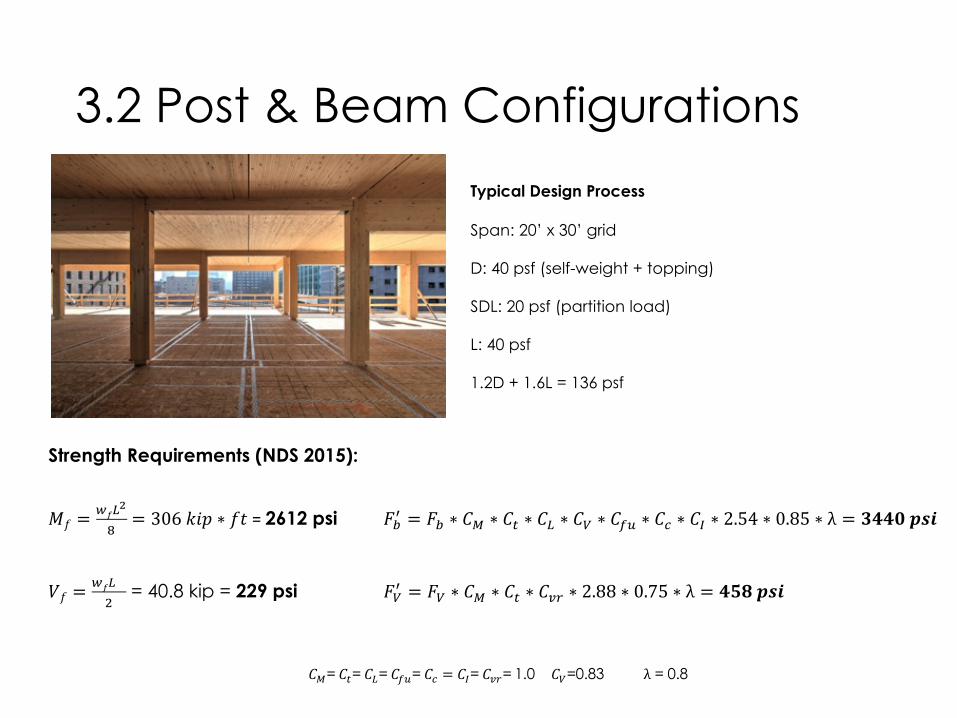
3.2 Post & Beam Configurations
Strength Requirements (NDS 2015):
!" =$%&
'
(= 306-./ ∗ "1 = 2612 psi 234 = 23 ∗ 56 ∗ 57 ∗ 5& ∗ 58 ∗ 5%9 ∗ 5: ∗ 5; ∗ 2.54 ∗ 0.85 ∗ λ = BCCDEFG
H" =$%&I
= 40.8 kip = 229 psi 284 = 28 ∗ 56 ∗ 57 ∗ 5JK ∗ 2.88 ∗ 0.75 ∗ λ = CMNEFG
56= 57= 5&= 5%9= 5: = 5;= 5JK=1.0 58=0.83 λ = 0.8
Typical Design Process
Span: 20’ x 30’ grid
D: 40 psf (self-weight + topping)
SDL: 20 psf (partition load)
L: 40 psf
1.2D + 1.6L = 136 psf

3.2 Post & Beam Configurations
Verify Vibration Performance:
Remember…
Limitations of the Simplified Method:
1. Bare floors with finishing, partitions and
furniture, but without heavy topping.
2. Vibrations are induced by normal walking
3. Well supported floors
4. Well-jointed CLT panels
5. Inclusion of the self-weight of CLT panels
only (ie. without live load)

AISC Design Guide 11 (2016)
3.2 Post & Beam Configurations
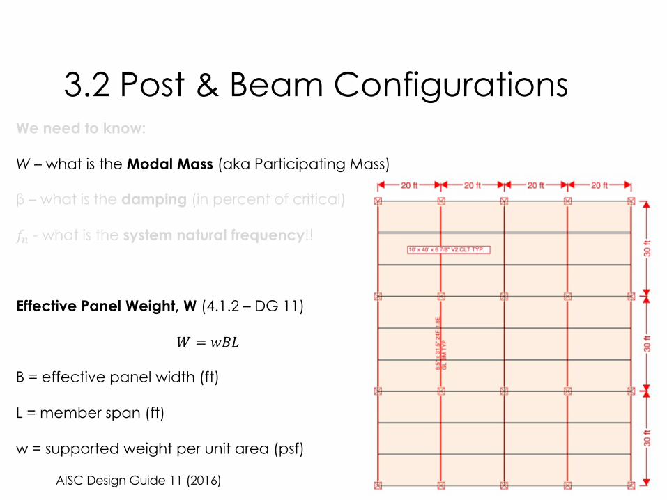
We need to know:
W – what is the Modal Mass (aka Participating Mass)
β – what is the damping (in percent of critical)
!" - what is the system natural frequency!!

AISC Design Guide 11 (2016)
3.2 Post & Beam ConfigurationsWe need to know:
W – what is the Modal Mass (aka Participating Mass)
β – what is the damping (in percent of critical)
!" - what is the system natural frequency!!

1.7 Dynamic Response to Footfall
CCIP-016 (2006)
M a(t) + C v(t) + K d(t) = F(t)T = 0.6s
fw = 1/T = 1.67 Hz
!" = %&'( = )*à Hz
Damped Response at Resonance
F(t)

AISC Design Guide 11 (2016)
3.2 Post & Beam ConfigurationsWe need to know:
W – what is the Modal Mass (aka Participating Mass)
β – what is the damping (in percent of critical)
!" - what is the system natural frequency!!
Dead Loads:
CLT + 1.5” conc. topping – 34.2 psf
Mechanical and Ceiling Installations – 4 psf
Superimposed Live Loads (Electronic Office) – 6 psf
AISC Design Guide 11 (2016)
3.2 Post & Beam ConfigurationsWe need to know:
W – what is the Modal Mass (aka Participating Mass)
β – what is the damping (in percent of critical)
!" - what is the system natural frequency!!
Effective Panel Weight, W (4.1.2 – DG 11)
# = %&'
B = effective panel width (ft)
L = member span (ft)
w = supported weight per unit area (psf)

AISC Design Guide 11 (2016)
3.2 Post & Beam ConfigurationsWe need to know:
W – what is the Modal Mass (aka Participating Mass)
β – what is the damping (in percent of critical)
!" - what is the system natural frequency!!
#$%& = )$%&*+,--_/0*+,--_0
123
4$%& ≤2
3!899:;<=>ℎ
)$%& = 2.0(>CD<EF8GH8IJJDF:F88I8>9!:III=KI)
4$%& = 20!> JDFH8IHK>ℎ #$%& = 2.0M1
NON
PQ⁄20!> = ST. UVW ≤ 60!>

AISC Design Guide 11 (2016)
3.2 Post & Beam ConfigurationsWe need to know:
W – what is the Modal Mass (aka Participating Mass)
β – what is the damping (in percent of critical)
!" - what is the system natural frequency!!
#$%& = ( ∗ *$%& ∗ +$%& = ,-, ,//123
( =44psf
*$%& = ,8. :3;
+$%& = ,/3;

AISC Design Guide 11 (2016)
3.2 Post & Beam ConfigurationsWe need to know:
W – what is the Modal Mass (aka Participating Mass)
β – what is the damping (in percent of critical)
!" - what is the system natural frequency!!
#$% = ($%)*+,,_.)*$%
/0%12
342
/$% ≤2
3!899:8;<=>ℎ
($% = 1.6 − 1.8** /$% = 30!> FGH<8;<=>ℎ
#$% = 1.8IJIK3.L
M.N3K3.L
OP⁄
30!> = RSTU ≤ 53.33!>

AISC Design Guide 11 (2016)
3.2 Post & Beam ConfigurationsWe need to know:
W – what is the Modal Mass (aka Participating Mass)
β – what is the damping (in percent of critical)
!" - what is the system natural frequency!!
#$% = ' ∗ )$% ∗ *$% = +,, ./0234
' =(44+3)psf (addself-weightofbeam)
)$% = ./4J
*$% = .04J
AISC Design Guide 11 (2016)
3.2 Post & Beam ConfigurationsWe need to know:
W – what is the Modal Mass (aka Participating Mass)
β – what is the damping (in percent of critical)
!" - what is the system natural frequency!!
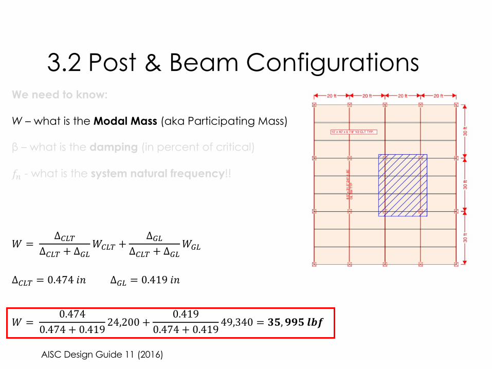
# = Δ'()Δ'() + Δ+(
#'() +Δ+(
Δ'() + Δ+(#+(
Δ'() = 0.47401 Δ+( = 0.41901
# = 0.4740.474 + 0.419 24,200 +
0.4190.474 + 0.419 49,340 = 78, 998:;<

AISC Design Guide 11 (2016)
3.2 Post & Beam ConfigurationsWe need to know:
W – what is the Modal Mass (aka Participating Mass)
β – what is the damping (in percent of critical)
!" - what is the system natural frequency!!
β = $. $&'(&. '%)

AISC Design Guide 11 (2016)
3.2 Post & Beam ConfigurationsWe need to know:
W – what is the Modal Mass (aka Participating Mass)
β – what is the damping (in percent of critical)
!" - what is the system natural frequency!!
!#$% = 0.18 ∗ ,-./0 = 1. 2356 !7$ = 0.18 ∗ ,
-8/ = 1. 3956
!:;:<=> = 0.18 ∗ ?Δ#$% + Δ7$
= B. C356

AISC Design Guide 11 (2016)
3.2 Post & Beam ConfigurationsCompare with Acceptance Criteria:
!"#= &'()*
+'.-.∗0121345
6∗7≤ !'
#
9:;= 0.005(0.5%@A;B9CDEF)
H: = 65lbf
AMNMO(P = 3.74TU
β = 0.025(2.5%XBDEDX9Y)
Z = 35995Y\A
9*;= ]. ]^_` ≫ 0.005

8.32 Hz
0.01 in
18.68 ft
207.6

3.3 System Comparison
Verify Vibration Performance:
Remember…
Limitations of the Simplified Method:
1. Bare floors with finishing, partitions and
furniture, but without heavy topping.
2. Vibrations are induced by normal walking
3. Well supported floors
4. Well-jointed CLT panels
5. Inclusion of the self-weight of CLT panels
only (ie. without live load, also neglects
topping weight)

AISC Design Guide 11 (2016)
3.3 System Comparison
!"#= &'()*
+'.-.∗0121345
6∗7≤ !'
#
!'#= 0.005(0.5%=>?@ABCDE)
GH = 65lbf
>MNO = 8. 32ST
β = 0.025(2.5%V@CDCVAW)
X = XMNO = 8465WZ>([\]^_W>`_C?ℎD=bWE)
A*?= c. cde ≫ 0.005
Compare MT panels on MT walls with DG 11 Acceptance Criteria:

AISC Design Guide 11 (2016)
3.3 System ComparisonCompare MT panels on MT walls with DG 11 Acceptance Criteria:
!"#= &'()*
+'.-.∗0121345
6∗7≤ !'
#
!'#= 0.005(0.5%=>?@ABCDE)
GH = 65lbf
>MNO = PP. QRST
β = 0.025(2.5%W@CDCWAX)
Y = YMNO = 8465X\>(]^_`aX>baC?ℎD=dXE)
A*?= e. eeR ≤ 0.005

AISC Design Guide 11 (2016)
3.3 System ComparisonCompare MT panels on MT walls with DG 11 Acceptance Criteria:
!"#= &'()*
+'.-.∗0121345
6∗7≤ !'
#
!'#= 0.005(0.5%=>?@ABCDE)
GH = 65lbf
>MNO = 8.32ST
β = V. VWX(8.5%Y@CDCYAZ)
[ = [MNO = 8465Z]>(^_`abZ>cbC?ℎD=eZE)
A*?= V. VVX ≤ 0.005

AISC Design Guide 11 (2016)
3.3 System ComparisonCompare MT panels on MT walls with DG 11 Acceptance Criteria:
!"#= &'()*
+'.-.∗0121345
6∗7≤ !'
#
!'#= 0.005(0.5%=>?@ABCDE)
GH = 65lbf
>MNO = 8.32ST
β = 0.025(2.5%V@CDCVAW)
X = XMNO = YZ, \Z]^_`(abc + D=eeCf?&hib)
A*?= ]. ]]j ≤ 0.005

4. Design & Analysis Suggestions

4.1 MT Vibration Analysis Flow Chart

4.1 MT Vibration Analysis Flow Chart

4.1 MT Vibration Analysis Flow Chart

4.1 MT Vibration Analysis Flow Chart

4.2 Insights from FEM
General:
Unique structural dynamic model is required with special consideration of the
following:
• boundary conditions (take advantage of continuity and supports that can
be considered rigid under small amplitude vibrations)
• loads applied to floor (is an appropriate mass being used to determine
fundamental frequency and resulting accelerations?)
• extent of modeled area (is an appropriate mass being represented for the
area under consideration?)
• Appropriate material properties (weights, dynamic modulus, etc.)
• Time History and FRF Analysis is very location specific, so be sure that you are
capturing a representative design scenario.
• Response Spectrum Methods are powerful and generally conservative but
remain sensitive to user inputs and appropriate modeling (eg. Damping)

4.3 Mitigation Techniques
Mass:
• Can you activate more mass?
• Can you add mass without making system more susceptible to vibrations?
Stiffness:
• Adjust panel and beam spans ! ∝ #$ à most efficient
• Increase timber element depth ! ∝ %& à next most efficient
• Account for fixity from reliable sources of support (eg. façade connections)
Damping:
• Only efficient at significant levels of damping

4.3 Mitigation Techniques
What if you could add stiffness AND mass?...

4.3 Mitigation Techniques Timber Concrete Composites

4.3 Mitigation Techniques Continuous Bonded Systems

Further Resources

• US CLT Handbook
• AISC Design Guide 2nd Edition (2016)
• CCIP-016 (2006)
• SCI-P354 (2009)
• HIVOSS (2007)
• CSA-086 (2014)
• EN 1995 design of timber structures (Eurocode 5)
• à See also supplier specific documents and white papers

Questions?This concludes The American Institute of Architects Continuing Education Systems Course
Adam GerberASPECT Structural [email protected]
This presentation was developed by a third party and is not funded by WoodWorks or the softwood lumber check-off.

TCC Economics