mass production cost estimation of direct hydrogen pem fuel
TRANSCRIPT

1
Mass Production Cost Estimation of Direct H2 PEM Fuel Cell Systems for
Transportation Applications:
2012 Update
October 18, 2012
Prepared By:
Brian D. James
Andrew B. Spisak
Revision 4

2
Sponsorship and Acknowledgements
This research was conducted under Award Number DE‐EE0005236 to the US Department of Energy. The
authors wish to thank Dr. Dimitrios Papageorgopoulos and Mr. Jason Marcinkoski of DOE’s Office of
Energy Efficiency and Renewable Energy (EERE) Fuel Cell Technologies (FCT) Program for their technical
and programmatic contributions and leadership.
Authors Contact Information
Strategic Analysis Inc. may be contacted at:
Strategic Analysis Inc.
4075 Wilson Blvd, Suite 200
Arlington VA 22203
(703) 527‐5410
www.sainc.com
The authors may be contacted at:
Brian D. James, [email protected] (703) 778‐7114

3
TableofAbbreviationsANL Argonne National Laboratory
atm atmospheres
BOL Beginning of Life
BOM Bill of Materials
BOP Balance of Plant
CCM catalyst coated membrane
CEM Integrated Compressor‐Expander‐Motor unit (used for air compression and exhaust gas
expansion)
DOE Department of Energy
DOT Department of Transportation
EERE DOE Office of Energy Efficiency and Renewable Energy
EOL end of life
ePTFE expanded polytetrafluoroethylene
FCT EERE Fuel Cell Technologies Program
FTA Federal Transit Administration
GDL Gas Diffusion Layer
H2 Hydrogen
MEA Membrane Electrode Assembly
mph miles per hour
NREL National Renewable Energy Laboratory
NSTF nano‐structured thin‐film (catalysts)
PEM Proton Exchange Membrane
PET polyethylene terephthalate
RFI Request for Information
SA Strategic Analysis, Inc.
TVS Twin Vortices Series (of Eaton Corp. compressors)
4
ForewordEnergy security is fundamental to the mission of the U.S. Department of Energy (DOE) and hydrogen fuel
cell vehicles have the potential to eliminate the need for oil in the transportation sector. Fuel cell
vehicles can operate on hydrogen, which can be produced domestically, emitting less greenhouse gasses
and pollutants than conventional internal combustion engine (ICE), advanced ICE, hybrid, or plug‐in
hybrid vehicles that are tethered to petroleum fuels. A diverse portfolio of energy sources can be used
to produce hydrogen, including nuclear, coal, natural gas, geothermal, wind, hydroelectric, solar, and
biomass. Thus, fuel cell vehicles offer an environmentally clean and energy‐secure transportation
pathway for transportation.
Fuel cell systems will have to be cost‐competitive with conventional and advanced vehicle technologies
to gain the market‐share required to influence the environment and reduce petroleum use. Since the
light duty vehicle sector consumes the most oil, primarily due to the vast number of vehicles it
represents, the DOE has established detailed cost targets for automotive fuel cell systems and
components. To help achieve these cost targets, the DOE has devoted research funding to analyze and
track the cost of automotive fuel cell systems as progress is made in fuel cell technology. The purpose of
these cost analyses is to identify significant cost drivers so that R&D resources can be most effectively
allocated toward their reduction. The analyses are annually updated to track technical progress in terms
of cost and to indicate how much a typical automotive fuel cell system would cost if produced in large
quantities (up to 500,000 vehicles per year).
Bus applications represent another area where fuel cell systems have an opportunity to make a national
impact on oil consumption and air quality. Consequently, beginning with this year (2012), annually
updated costs analyses will be conducted for PEM fuel cell passenger buses as well. Fuel cell systems for
light duty automotive and buses share many similarities and indeed may even utilize identical stack
hardware. Thus the analysis of bus fuel cell power plants is a logical extension of the light duty
automotive power system analysis. Primary differences between the two applications include the
installed power required (80kWelectric_net for automotive vs. ~160kWelectric_net for a 40’ transit bus), desired
power plant durability (nominally 5,000 hours lifetime for automotive vs. 25,000 hours lifetime for
buses), and annual manufacturing rate (up to 500,000 systems/year for an individual top selling
automobile model vs. <1000 systems/year for total transit bus sales in the US).
The capacity to produce fuel cell systems at high manufacturing rates does not yet exist, and significant
investments will have to be made in manufacturing development and facilities in order to enable it.
Once the investment decisions are made, it will take several years to develop and fabricate the
necessary manufacturing facilities. Furthermore, the supply chain will need to develop which requires
negotiation between suppliers and system developers, with details rarely made public. For these
reasons, the DOE has consciously decided not to analyze supply chain scenarios at this point, instead
opting to concentrate its resources on solidifying the tangible core of the analysis, i.e. the manufacturing
and materials costs.
5
The DOE uses these analyses as tools for R&D management and tracking technological progress in terms
of cost. Consequently, non‐technical variables are held constant to elucidate the effects of the technical
variables. For example, the cost of platinum is held at $1,100 per troy ounce to insulate the study from
unpredictable and erratic platinum price fluctuations. Sensitivity analyses are conducted to explore the
effects of non‐technical parameters.
To maximize the benefit of our work to the fuel cell community, Strategic Analysis Inc. (SA) strives to
make each analysis as transparent as possible. The transparency of the assumptions and methodology
serve to strengthen the validity of the analysis. We hope that these analyses have been and will
continue to be valuable tools to the hydrogen and fuel cell R&D community.
6
TableofContents1 Overview ............................................................................................................................................... 8
2 Project Approach .................................................................................................................................. 9
2.1 Bus System .................................................................................................................................. 11
3 System Schematics and Bills of Materials ........................................................................................... 14
3.1 2012 Automotive System Schematic .......................................................................................... 17
3.2 2012 Bus System Schematic ........................................................................................................ 18
4 System Cost Summaries ...................................................................................................................... 19
4.1 Cost Summary of the 2012 Automotive System ......................................................................... 19
4.2 Cost Summary of the 2012 Bus System ...................................................................................... 21
5 Automotive Power System Changes since the 2011 Report .............................................................. 22
5.1 2012 ANL Polarization Optimization ........................................................................................... 23
5.2 Ionomer Cost Reduction ............................................................................................................. 26
5.3 Sub‐Gaskets ................................................................................................................................. 27
5.4 GDL Cost Reduction .................................................................................................................... 28
5.5 Additional Minor Changes .......................................................................................................... 29
5.5.1 Piping Configuration Update ............................................................................................... 29
5.5.2 Purge Valve Upgrade ........................................................................................................... 31
5.5.3 Crimping Roller Replacing Hot Pressing .............................................................................. 33
5.5.4 Membrane Air Humidifier Design Change .......................................................................... 33
6 Bus Fuel Cell Power System ................................................................................................................ 34
6.1 Bus Power System Overview and Comparison with Automotive Power System ....................... 34
6.2 Bus System Performance Parameters ......................................................................................... 36
6.2.1 Power Level ......................................................................................................................... 36
6.2.2 Polarization Performance Basis .......................................................................................... 36
6.2.3 Catalyst Loading .................................................................................................................. 37
6.2.4 Operating Pressure ............................................................................................................. 38
6.2.5 Stack Operating Temperature ............................................................................................. 38
6.2.6 Cell Active Area and System Voltage .................................................................................. 39
6.3 Air Compression System ............................................................................................................. 39
6.4 Bus System Balance of Plant Components.................................................................................. 42
6.5 Bus System Vertical Integration .................................................................................................. 43
7 Capital and Quality Control Equipment .............................................................................................. 44
8 Automotive Simplified Cost Model Function ...................................................................................... 44
9 Lifecycle Cost Analysis ......................................................................................................................... 47
10 Sensitivity Studies ........................................................................................................................... 53
10.1 Single Variable Analysis ............................................................................................................... 53
10.1.1 Single Variable Automotive Analysis ................................................................................... 53
10.1.2 Automotive Analysis at a Pt price of $1550/troy ounce ..................................................... 54
10.1.3 Single Variable Bus Analysis ................................................................................................ 55
10.2 Monte Carlo Analysis .................................................................................................................. 56

7
10.2.1 Monte Carlo Automotive Analysis ...................................................................................... 57
10.2.2 Monte Carlo Bus Analysis .................................................................................................... 58
10.3 Analysis of Bus Operation at Higher Pressure with an Exhaust Gas Expander ........................... 60
11 Summary Observations of the 2012 Automotive and Bus Analyses .............................................. 61
8
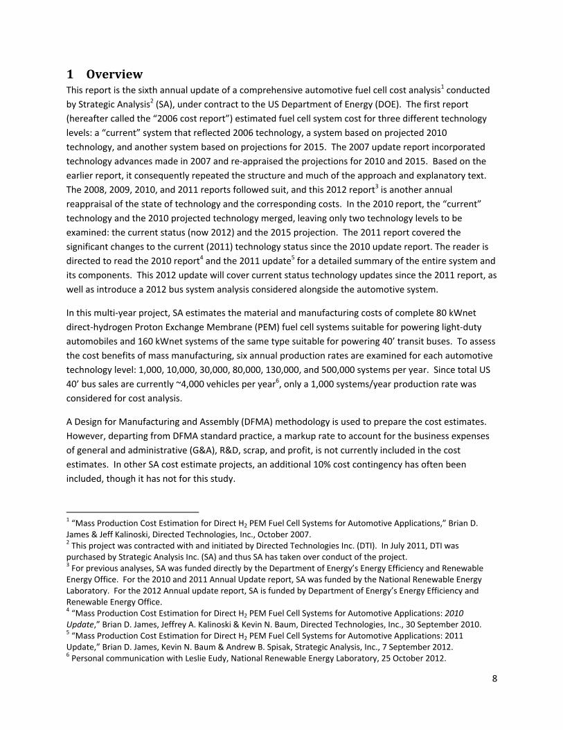
1 OverviewThis report is the sixth annual update of a comprehensive automotive fuel cell cost analysis1 conducted
by Strategic Analysis2 (SA), under contract to the US Department of Energy (DOE). The first report
(hereafter called the “2006 cost report”) estimated fuel cell system cost for three different technology
levels: a “current” system that reflected 2006 technology, a system based on projected 2010
technology, and another system based on projections for 2015. The 2007 update report incorporated
technology advances made in 2007 and re‐appraised the projections for 2010 and 2015. Based on the
earlier report, it consequently repeated the structure and much of the approach and explanatory text.
The 2008, 2009, 2010, and 2011 reports followed suit, and this 2012 report3 is another annual
reappraisal of the state of technology and the corresponding costs. In the 2010 report, the “current”
technology and the 2010 projected technology merged, leaving only two technology levels to be
examined: the current status (now 2012) and the 2015 projection. The 2011 report covered the
significant changes to the current (2011) technology status since the 2010 update report. The reader is
directed to read the 2010 report4 and the 2011 update5 for a detailed summary of the entire system and
its components. This 2012 update will cover current status technology updates since the 2011 report, as
well as introduce a 2012 bus system analysis considered alongside the automotive system.
In this multi‐year project, SA estimates the material and manufacturing costs of complete 80 kWnet
direct‐hydrogen Proton Exchange Membrane (PEM) fuel cell systems suitable for powering light‐duty
automobiles and 160 kWnet systems of the same type suitable for powering 40’ transit buses. To assess
the cost benefits of mass manufacturing, six annual production rates are examined for each automotive
technology level: 1,000, 10,000, 30,000, 80,000, 130,000, and 500,000 systems per year. Since total US
40’ bus sales are currently ~4,000 vehicles per year6, only a 1,000 systems/year production rate was
considered for cost analysis.
A Design for Manufacturing and Assembly (DFMA) methodology is used to prepare the cost estimates.
However, departing from DFMA standard practice, a markup rate to account for the business expenses
of general and administrative (G&A), R&D, scrap, and profit, is not currently included in the cost
estimates. In other SA cost estimate projects, an additional 10% cost contingency has often been
included, though it has not for this study.
1 “Mass Production Cost Estimation for Direct H2 PEM Fuel Cell Systems for Automotive Applications,” Brian D. James & Jeff Kalinoski, Directed Technologies, Inc., October 2007. 2 This project was contracted with and initiated by Directed Technologies Inc. (DTI). In July 2011, DTI was purchased by Strategic Analysis Inc. (SA) and thus SA has taken over conduct of the project. 3 For previous analyses, SA was funded directly by the Department of Energy’s Energy Efficiency and Renewable Energy Office. For the 2010 and 2011 Annual Update report, SA was funded by the National Renewable Energy Laboratory. For the 2012 Annual update report, SA is funded by Department of Energy’s Energy Efficiency and Renewable Energy Office. 4 “Mass Production Cost Estimation for Direct H2 PEM Fuel Cell Systems for Automotive Applications: 2010 Update,” Brian D. James, Jeffrey A. Kalinoski & Kevin N. Baum, Directed Technologies, Inc., 30 September 2010. 5 “Mass Production Cost Estimation for Direct H2 PEM Fuel Cell Systems for Automotive Applications: 2011 Update,” Brian D. James, Kevin N. Baum & Andrew B. Spisak, Strategic Analysis, Inc., 7 September 2012. 6 Personal communication with Leslie Eudy, National Renewable Energy Laboratory, 25 October 2012.
9
In general, the system designs do not change with production rate, but material costs, manufacturing
methods, and business‐operational assumptions do vary. Cost estimation at very low manufacturing
rates (below 1,000 systems per year) presents particular challenges. Traditional low‐cost mass‐
manufacturing methods are not cost‐effective due to high per‐unit setup and tooling costs and less
defined, less automated operations are typically employed. For some repeat parts within the fuel cell
stack (e.g. the membrane electrode assemblies (MEAs) and bipolar plates), such a large number of
pieces are needed for each system that even at low system production rates (1,000/year), hundreds of
thousands of individual parts are needed annually. Thus for these parts, mass‐manufacturing cost
reductions are achieved even at low system production rates. However, other stack components (e.g.
end plates and current collectors), and all balance of plant (BOP) equipment (e.g. compressors, hoses
and valves), do not benefit from this manufacturing multiplier effect.
The 2012 system reflects the authors’ best estimate of current technology and, with only a few
exceptions, is not based on proprietary information. Public presentations by fuel cell companies and
other researchers along with extensive review of the patent literature are used as the basis for much of
the design and fabrication technologies. Consequently, the presented information may lag behind what
is being done “behind the curtain” in fuel cell companies. Nonetheless, the current‐technology system
provides a benchmark against which the impact of future technologies may be compared. Taken
together, the analysis of this system provides a good sense of the likely range of costs for mass‐
produced automotive fuel cell systems and of the dependence of cost on system performance,
manufacturing, and business‐operational assumptions.
2 ProjectApproachThe system examined does not reflect the design of any one manufacturer but is a composite of the best
elements from a number of designs. The automotive system is normalized to a system output power of
80 kWnet and the bus system to 160 kWnet, although the gross powers for both systems are derived
from the parasitic load of the BOP components. The stack efficiency7 at rated power is set at 55%, to
match the DOE target value. Multiplying this by the theoretical open circuit cell voltage (1.229 V) yields
a cell voltage of 0.676 V at peak power. Previous iterations of this report had used an assumed oxidant
stoichiometry8 of 1.5‐2.5. However, the addition of the ANL curve fit and subsequent parameter
optimization has changed these parameters for 2011 and 2012 as will be discussed in Section 5.1.
The main fuel cell subsystems included in this analysis are:
• Fuel cell stacks
• Air loop
• Humidifier and water recovery loop
• High‐temperature coolant loop
• Low‐temperature coolant loop
• Fuel loop (but not fuel storage)
7 Stack efficiency is defined as voltage efficiency X H2 utilization = Cell volts/1.229 X 100%. 8 Air stoichiometry was 2.5 for the 2010 model and dropped to 1.5 for 2011.
10
• Fuel cell system controller
• Sensors
Some vehicle electrical system components explicitly excluded from the analysis include:
• Main vehicle battery or ultra‐capacitor9
• Electric traction motor (that drives the vehicle wheels)
• Traction inverter module (TIM) (for control of the traction motor)
• Vehicle frame, body, interior, or comfort related features (e.g., driver’s instruments, seats, and
windows)
Many of the components not included in this study are significant contributors to the total fuel cell
vehicle cost; however their design and cost are not necessarily dependent on the fuel cell configuration
or stack operating conditions. Thus, it is our expectation that the fuel cell system defined in this report
is applicable to a variety of vehicle body types and drive configurations.
As mentioned above, the costing methodology employed in this study is the Design for Manufacture and
Assembly technique (DFMA10). The Ford Motor Company has formally adopted the DFMA process as a
systematic means for the design and evaluation of cost optimized components and systems. These
techniques are powerful and flexible enough to incorporate historical cost data and manufacturing
acumen that have been accumulated by Ford since the earliest days of the company. Since fuel cell
system production requires some manufacturing processes not normally found in automotive
production, the formal DFMA process and SA’s manufacturing database are buttressed with budgetary
and price quotations from experts and vendors in other fields. It is possible to choose cost‐optimized
manufacturing processes and component designs and accurately estimate the cost of the resulting
products by combining historical knowledge with the technical understanding of the functionality of the
fuel cell system and its component parts.
The cost for any component analyzed via DFMA techniques includes direct material cost, manufacturing
cost, assembly costs, and markup. Direct material costs are determined from the exact type and mass of
material employed in the component. This cost is usually based upon either historical volume prices for
the material or vendor price quotations. In the case of materials not widely used at present, the
manufacturing process must be analyzed to determine the probable high‐volume price for the material.
The manufacturing cost is based upon the required features of the part and the time it takes to generate
those features in a typical machine of the appropriate type. The cycle time can be combined with the
“machine rate,” the hourly cost of the machine based upon amortization of capital and operating costs,
and the number of parts made per cycle to yield an accurate manufacturing cost per part. The assembly
costs are based upon the amount of time to complete the given operation and the cost of either manual
labor or of the automatic assembly process train. The piece cost derived in this fashion is quite accurate
9 Fuel cell automobiles may be either “purebreds” or “hybrids” depending on whether they have battery (or ultracapacitor) electrical energy storage or not. This analysis only addresses the cost of an 80 kW fuel cell power system and does not include the cost of any peak‐power augmentation or hybridizing battery. 10 Boothroyd, G., P. Dewhurst, and W. Knight. “Product Design for Manufacture and Assembly, Second Edition,” 2002.
11
as it is based upon an exact physical manifestation of the part and the technically feasible means of
producing it as well as the historically proven cost of operating the appropriate equipment and
amortizing its capital cost. Normally (though not in this report), a percentage markup is applied to the
material, manufacturing, and assembly cost to account for profit, general and administrative (G&A)
costs, research and development (R&D) costs, and scrap costs. This percentage typically varies with
production rate to reflect the efficiencies of mass production. It also changes based on the business
type and on the amount of value that the manufacturer or assembler adds to the product.
Cost analyses were performed for mass‐manufactured systems at six production rates: 1,000, 10,000,
30,000, 80,000, 130,000, and 500,000 systems per year. System designs did not change with production
rate, but material costs, manufacturing methods, and business‐operational assumptions (such as
markup rates) often varied. Fuel cell stack component costs were derived by combining manufacturers’
quotes for materials and manufacturing with detailed DFMA‐style analysis.
For some components (e.g. the bipolar plates and the coolant and end gaskets), multiple designs or
manufacturing approaches were analyzed. The options were carefully compared and contrasted, then
examined within the context of the rest of the system. The best choice for each component was
included in the 2012 baseline configuration. Because of the interdependency of the various
components, the selection or configuration of one component sometimes affects the selection or
configuration of another. In order to handle these combinations, the model was designed with switches
for each option, and logic was built in that automatically adjusts variables as needed. As such, the
reader should not assume that accurate system costs could be calculated by merely substituting the cost
of one component for another, using only the data provided in this report. Instead, data provided on
various component options should be used primarily to understand the decision process used to select
the approach selected for the baseline configurations.
2.1 BusSystemFuel cell transit buses represent a growing market segment and a logical application of fuel cell
technology. Fuel cell transit buses enjoy several advantages over fuel cell automobiles, particularly in
the early years, due the availability of centralized refueling, higher bus power levels (which generally are
more economical on a $/kW basis), dedicated maintenance and repair teams, high vehicle utilization,
(relatively) less cost sensitivity, and the purchasing decision makers are typically local governments or
quasi‐government agencies whom are often early adopters of environmentally clean technologies.
The transit bus market generally consists of 40’ buses (the common “Metro” bus variety) and 30’ buses
(typically used for Suburban/Commuter11 to rail station routes). While the 30’ buses can be simply
truncated versions of 40’ buses, they more commonly are based on a lighter and smaller chassis (often
school bus frames) than their 40’ counterparts. Whereas 40’ buses typically have an expected lifetime
of 500k to 1M miles, 30’ buses generally have a lower expected lifetime, nominally 200k miles.
11 Commuter buses are typically shorter in overall length (and wheel base) to provide ease of transit through neighborhoods, a tighter turning radius, and more appropriate seating for a lower customer user base.
12
There are generally three classes of fuel cell bus architecture12:
hybrid electric: which typically utilize full size fuel cells for motive power and batteries for
power augmentation;
battery dominant: which use the battery as the main power source and typically use a relatively
small fuel cell system to “trickle charge” the battery and thereby extend battery range;
plug‐in: which operate primarily on the battery while there is charge, and use the fuel cell as a
backup power supply or range extender.
In May 2011, the US Department of Energy issued a Request for Information (RFI) seeking input13 from
industry stakeholders and researchers on performance, durability, and cost targets for fuel cell transit
buses and their fuel cell power systems. A joint DOE‐Department of Transportation (DOT)/Federal
Transit Administration (FTA) workshop was held to discuss the responses, and led to DOE publishing fuel
cell bus targets for performance and cost as shown in Figure 1. While not explicitly used in this cost
analysis, these proposed targets are used as a guideline for defining the bus fuel cell power plant
analyzed in the cost study.
The cost analysis in this report is based on the assumption of a 40’ transit bus. Power levels for this class
of bus vary widely based primarily on terrain/route and environmental loads. Estimates of fuel cell
power plant required14 net power can be as low as 75 kW for a flat route in a mild climate to 180+kW for
a hillier urban route in a hot climate. Accessory loads on buses are much higher than on light duty
passenger cars. Electric power is needed for climate control (i.e. cabin air conditioning and heating),
opening and closing the doors (which also impacts climate control), and lighting loads. In a hot climate,
such as Dallas Texas, accessory loads can reach 30‐60 kW, although 30‐40 kW is more typical15. Industry
experts16 note that the trend may be toward slightly lower fuel cell power levels as future buses become
more heavily hybridized and make use of high‐power‐density batteries (particularly lithium chemistries).
The cost analysis in this report is based on a 160 kWnet fuel cell bus power plant. This power level is
within the approximate range of existing fuel cell bus demonstration projects17 as exemplified by the
150 kW Ballard fuel cell buses18 used in Whistler, Canada for the 2010 winter Olympics, and the 120kW
UTC power PureMotion fuel cell bus fleets in California19 and Connecticut. Selection of a 160 kWnet
power level is also convenient because it is twice the power of the nominal 80kWnet systems used for the
light duty automotive analysis, thereby easily facilitating comparisons to the use of two auto power
plants.
12 Personal communication with Leslie Eudy, National Renewable Energy Laboratory, 25 October 2012. 13 “Fuel Cell Transit Buses”, R. Ahluwalia, , X. Wang, R. Kumar, Argonne National Laboratory, 31 January 2012. 14 Personal communication with Larry Long, Ballard Power Systems, September 2012. 15 Personal communication with Larry Long, Ballard Power Systems, September 2012. 16 Personal communication with Peter Bach, Ballard Power Systems, October 2012. 17 “Fuel Cell Transit Buses”, R. Ahluwalia, , X. Wang, R. Kumar, Argonne National Laboratory, 31 January 2012. 18 The Ballard bus power systems are typically referred to by their gross power rating (150kW). They deliver approximately 140kW net. 19 “SunLine Unveils Hydrogen‐Electric Fuel Cell Bus: Partner in Project with AC Transit”, article at American Public Transportation Association website, 12 December 2005, http://www.apta.com/passengertransport/Documents/archive_2251.htm

13
Parameter Units 2012 Status Ultimate Target
Bus Lifetime years/miles 5/100,000 a 12/500,000 Power Plant Lifetimeb,c hours 12,000 25,000 Bus Availability % 60 90 Fuel Fills d per day 1 1 (<10 min) Bus Cost e $ 2,000,000 600,000 Power Plant Costb, e $ 700,000 200,000 Road Call Frequency (Bus/Fuel‐Cell System)
miles between road calls (MBRC)
2,500/10,000 4,000/20,000
Operating Time hours per day/days per week
19/7 20/7
Scheduled and Unscheduled Maintenance Cost f
$/mile 1.20 0.40
Range miles 270 300 Fuel Economy mgdeg 7 8 a Status represents NREL fuel cell bus evaluation data. New buses are currently projected to have 8 year/300,000 mile lifetime.
b The power plant is defined as the fuel cell system and the battery system. The fuel cell system includes supporting
subsystems such as the air, fuel, coolant, and control subsystems. Power electronics, electric drive, and hydrogen storage tanks
are excluded.
c According to an appropriate duty cycle.
d Multiple sequential fuel fills should be possible without increase in fill time.
e Cost projected to a production volume of 400 systems per year. This production volume is assumed for analysis purposes
only, and does not represent an anticipated level of sales.
f Excludes mid‐life overhaul of power plant.
Figure 1: Proposed DOE targets for fuel cell‐powered transit buses (From US DOE20)
The transit bus driving schedule is expected to consist of much more frequent starts and stops, low
fractional time at idle power (due to high and continuous climate control loads), and low fractional time
at full power compared to light‐duty automotive drive cycles21. While average bus speeds depend on
many factors, representative average bus speeds22 are 11‐12 miles per hour (mph), with the extremes
being a New York City type route (~6 mph average) and a commuter style bus route (~23 mph average).
No allowance has been made in the cost analysis to reflect the impact of a particular bus driving
schedule.
There are approximately 4,000 forty‐foot transit buses sold each year in the United States23. However,
each transit agency typically orders its own line of customized buses. Thus while orders of identical
buses may reach 500 vehicles at the high end, sales are typically much lower. Smaller transit agencies
20 “Fuel Cell Bus Targets”, US Department of Energy Fuel Cell Technologies Program Record, Record # 12012, March 2, 2012. http://www.hydrogen.energy.gov/pdfs/12012_fuel_cell_bus_targets.pdf 21 Such as the Federal Urban Drive Schedule (FUDS), Federal Highway Drive Schedule (FHDS), Combined Urban/Highway Drive Cycle, LA92, or US06. 22 Personal communication with Leslie Eudy, National Renewable Energy Laboratory, 25 October 2012. 23 Personal communication with Leslie Eudy, National Renewable Energy Laboratory, 25 October 2012.

14
sometimes pool their orders to achieve more favorable pricing. Of all bus types24 in 2011, diesel engine
power plants are the most common (63.5%), followed by CNG/LNG/Blends (at 18.6%), and hybrids
(electrics or other) (at only 8.8%). Of hybrid electric 40’ transit bus power plants, BAE Systems and
Alison are the dominant power plant manufacturers. These factors combine to make quite small the
expected annual manufacturing output for a particular manufacturer of bus fuel cell power plant.
Consequently, 1,000 buses per year is selected as the single annual manufacturing rate to be examined
in the cost study. This is considered a fairly high estimate for near‐term fuel cell bus sales, however
could alternately be viewed on a low estimate if foreign fuel cell bus sales are included.
3 SystemSchematicsandBillsofMaterialsSystem schematics are a useful method of identifying the main components within a system and how
they interact. System flow schematics for each of the systems in the current report are shown below.
Note that for clarity, only the main system components are identified in the flow schematics. Figure 2
and Figure 3 display the power system diagrams corresponding to the 2011 and 2012 automotive
systems. As the analysis has evolved throughout the course of the annual updates, there has been a
general trend toward system simplification. This reflects improvements in technology so as not to need
as many parasitic supporting systems and facilitates reduced cost. The path to system simplification is
likely to continue, and, in the authors’ opinion, remains necessary to achieve or surpass cost parity with
internal combustion engines.
The authors have conducted annually updated DFMA analysis of automotive fuel cell systems since
2006. Consequently, to better convey how the fuel cell system has evolved with time, key changes in
the system schematics are enumerated below for each year’s system (beginning in 2008).
The 2008 fuel cell power system was a fairly standard direct‐hydrogen pressurized‐air fuel cell system
configuration. Main features of the 2008 system included:
2 separate liquid‐cooled fuel cell stacks, plumbed in parallel but connected electrically in
series
A twin‐lobe air compressor
A twin‐lobe exhaust air expander
A water spray humidifier to both humidify and cool the inlet cathode air after compression
A liquid/gas heat exchanger to condense water in the exhaust stream for recycle to the air
humidifier
A high‐temperature coolant loop of water/ethylene glycol to maintain a stack temperature of
~80°C An exhaust loop of water/ethylene‐glycol mixture to provide cooling for the exhaust air
condenser
24 2012 Public Transportation Fact Book, American Public Transportation Association (APTA), 63rd Edition September 2012. Accessed February 2013 at http://www.apta.com/resources/statistics/Documents/FactBook/APTA_2012_Fact%20Book.pdf

15
o Only 67% of this loop is included in the system cost, because the remainder of its
duty is for components outside of the scope of this analysis
Twin hydrogen ejectors(high‐flow and low‐flow) to utilize the high pressure (> 300 psi) in the
hydrogen storage tanks to re‐circulate anode hydrogen
The 2009 system was much simpler than that of 2008, and differed in the following key ways:
The number of stacks was reduced from 2 to 1
A centrifugal compressor replaced the twin‐lobe compressor
A centrifugal expander replaced the twin‐lobe expander
A membrane humidifier replaced the water spray humidifier
The exhaust gas condenser was eliminated (because there was no need to capture liquid
water for the water spray humidifier)
The low‐temperature cooling loop was eliminated (because the condenser had been
eliminated)
The high‐temperature radiator was slightly smaller (because the peak operating temperature
of the stack had been increased and thus there was a larger temperature difference between
the coolant and the ambient temperature)
The 2010 technology system reflected both additions and subtractions to the 2009 BOP, though there
was a net increase in complexity. This increase is primarily attributed to feedback received from Dr.
Rajesh Ahuwalia of Argonne National Laboratory wherein his modeling work identified the need for both
a demister and an air precooler, the latter of which requires the re‐addition of a low‐temperature loop.
The 2010 system configuration differed from the 2009 version in the following key ways:
The ejector system was reconfigured with the assumption that the fuel storage system (not
included in the cost analysis) handles some of the pressure regulation duties:
o The proportional valve was removed
o The pressure transducer was removed
o An over‐pressure cut‐off (OPCO) valve was added
o Check valves were added
o An inline filter for gas purity excursions was added
A demister was added in order to ensure that no ice formed in the expander
A new low‐temperature cooling loop (different from the one in the 2008 system) was
inserted into the system to cool the previously air‐cooled CEM and the new air precooler. It
also cooled the traction inverter module (TIM), but as this was outside the boundary of the
cost analysis, the fraction of the LTL cost proportionate to the TIM’s cooling duty (61%) was
excluded from the model.
The high‐temperature radiator was once again smaller than the previous year (because the
peak operating temperature of the stack had been increased and thus there was a larger
temperature difference between the coolant and the ambient temperature).
16
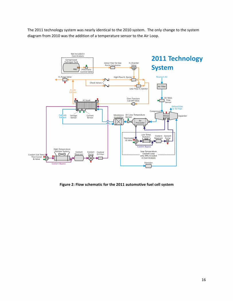
The 2011 technology system was nearly identical to the 2010 system. The only change to the system
diagram from 2010 was the addition of a temperature sensor to the Air Loop.
Figure 2: Flow schematic for the 2011 automotive fuel cell system
17
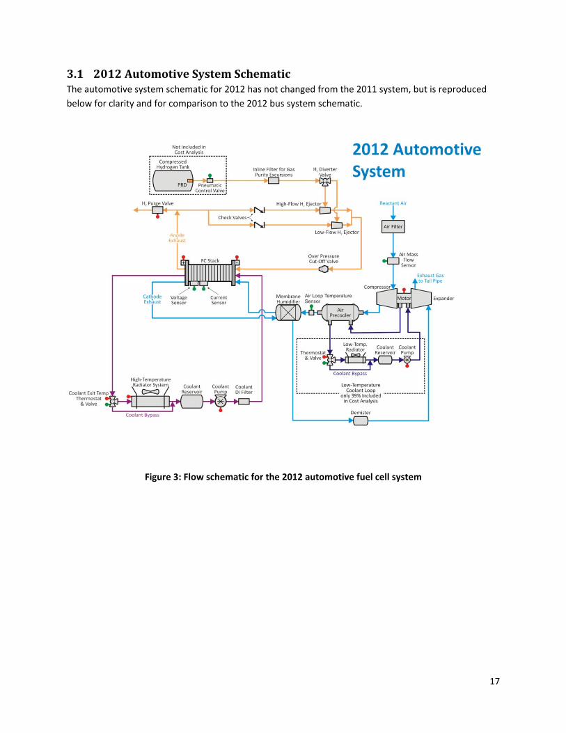
3.1 2012AutomotiveSystemSchematicThe automotive system schematic for 2012 has not changed from the 2011 system, but is reproduced
below for clarity and for comparison to the 2012 bus system schematic.
Figure 3: Flow schematic for the 2012 automotive fuel cell system
18
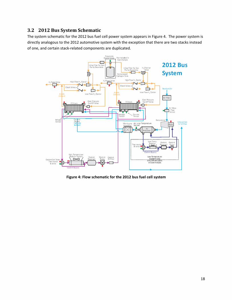
3.2 2012BusSystemSchematicThe system schematic for the 2012 bus fuel cell power system appears in Figure 4. The power system is
directly analogous to the 2012 automotive system with the exception that there are two stacks instead
of one, and certain stack‐related components are duplicated.
Figure 4: Flow schematic for the 2012 bus fuel cell system

19
4 SystemCostSummariesComplete fuel cell power systems are configured to allow assembly of comprehensive system Bills of
Materials, which in turn allow comprehensive assessments of system cost. Key parameters for the 2012
automotive and bus fuel cell power systems are shown in Figure 5 below, with cost result summaries
detailed in subsequent report sections.
2011 Auto Technology
System
2012 Auto Technology
System
2012 Bus Technology
SystemPower Density (mW/cm
2) 1,100 984 716
Total Pt loading (mgPt/cm2) 0.186 0.196 0.4
Net Power (kWnet) 80 80 160
Gross Power (kWgross) 89.25 88.24 177.10
Operating Pressure (atm) 3.00 2.50 1.80
Peak Stack Temp. (°C) 95 87 74
Active Cells 369 369 739
Membrane Material Nafion on 25‐micron ePTFE Nafion on 25‐micron ePTFE Nafion on 25‐micron ePTFE
Radiator/ Cooling SystemAluminum Radiator,
Water/Glycol Coolant,
DI Filter, Air Precooler
Aluminum Radiator,
Water/Glycol Coolant,
DI Filter, Air Precooler
Aluminum Radiator,
Water/Glycol Coolant,
DI Filter, Air Precooler
Bipolar Plates Stamped SS 316L with TreadStone Coating Stamped SS 316L with TreadStone Coating Stamped SS 316L with TreadStone Coating
Air CompressionCentrifugal Compressor,
Radial‐Inflow Expander
Centrifugal Compressor,
Radial‐Inflow Expander
Centrifugal Compressor,
Without Expander
Gas Diffusion Layers Carbon Paper Macroporous Layer with
Microporous Layer
Carbon Paper Macroporous Layer with
Microporous Layer (Ballard Cost)
Carbon Paper Macroporous Layer with
Microporous Layer (Ballard Cost)
Catalyst Application Nanostructured Thin Film (NSTF) Nanostructured Thin Film (NSTF) Nanostructured Thin Film (NSTF)
Air Humidification Tubular Membrane Humidifier Tubular Membrane Humidifier Tubular Membrane Humidifier
Hydrogen Humidification None None None
Exhaust Water Recovery None None None
MEA Containment and
Gasketing
Injection‐Molded LIM Hydrocarbon MEA
Frame/Gasket around Hot‐Pressed M&E
Screen Printed Seal on MEA Subgaskets,
GDL crimpted to CCM
Screen Printed Seal on MEA Subgaskets,
GDL crimpted to CCM
Coolant & End GasketsLaser Welded (Cooling),
Screen‐Printed Adhesive Resin (End)
Laser Welded (Cooling),
Screen‐Printed Adhesive Resin (End)
Laser Welded (Cooling),
Screen‐Printed Adhesive Resin (End)
Freeze Protection Drain Water at Shutdown Drain Water at Shutdown Drain Water at Shutdown
Hydrogen Sensors2 for FC System
1 for Passenger Cabin (not in cost estimate)
1 for Fuel System (not in cost estimate)
2 for FC System
1 for Passenger Cabin (not in cost estimate)
1 for Fuel System (not in cost estimate)
2 for FC System
1 for Passenger Cabin (not in cost estimate)
1 for Fuel System (not in cost estimate)
End Plates/
Compression System
Composite Molded End Plates with Compression
Bands
Composite Molded End Plates with
Compression Bands
Composite Molded End Plates with Compression
Bands
Stack Conditioning (hrs) 5 5
Figure 5: Summary chart of the 2011 and 2012 automotive systems
4.1 CostSummaryofthe2012AutomotiveSystemResults of the cost analysis of the 2012 automotive technology system at each of the six annual
production rates are shown below. Figure 6 details the cost of the stacks, Figure 7 details the cost of the
balance of plant components, and Figure 8 details the cost summation for the system.
5

20
Figure 6: Detailed stack cost for the 2012 automotive technology system
Figure 7: Detailed balance of plant cost for the 2012 automotive technology system
Figure 8: Detailed system cost for the 2012 automotive technology system
Annual Production Rate 1,000 10,000 30,000 80,000 130,000 500,000System Net Electric Power (Output) 80 80 80 80 80 80
System Gross Electric Power (Output) 88.24 88.24 88.24 88.24 88.24 88.24
Bipolar Plates (Stamped) $1,819.33 $436.67 $411.17 $395.16 $395.55 $392.33
MEAs $9,082.91 $2,623.29 $1,758.30 $1,415.04 $1,307.39 $1,103.35
Membranes $3,518.73 $882.16 $495.01 $336.62 $276.84 $171.17
Catalyst Ink & Application (NSTF) $1,452.68 $816.70 $770.79 $764.76 $763.42 $759.85
GDLs $2,137.41 $638.84 $359.04 $214.65 $166.39 $82.09
M & E Cutting & Slitting $487.44 $50.71 $18.36 $8.24 $5.91 $3.15
MEA Gaskets $1,486.64 $234.87 $115.10 $90.78 $94.83 $87.10
Coolant Gaskets (Laser Welding) $212.59 $41.52 $28.59 $26.98 $26.60 $26.01
End Gaskets (Screen Printing) $149.48 $15.04 $5.08 $1.97 $1.25 $0.53
End Plates $96.65 $33.18 $29.35 $24.93 $22.55 $17.12
Current Collectors $52.57 $11.40 $7.61 $5.74 $5.16 $4.53
Compression Bands $10.00 $9.00 $8.00 $6.00 $5.50 $5.00
Stack Housing $60.50 $10.32 $6.61 $5.51 $4.94 $4.37
Stack Assembly $76.12 $59.00 $40.69 $34.95 $33.62 $32.06Stack Conditioning $170.88 $56.78 $53.87 $47.18 $41.38 $28.06
Total Stack Cost $11,731.03 $3,296.20 $2,349.26 $1,963.46 $1,843.95 $1,613.36
Total Stack Cost ($/kWnet) $146.64 $41.20 $29.37 $24.54 $23.05 $20.17Total Stack Cost ($/kWgross) $132.94 $37.35 $26.62 $22.25 $20.90 $18.28
2012 Automotive System
Annual Production Rate 1,000 10,000 30,000 80,000 130,000 500,000
System Net Electric Power (Output) 80 80 80 80 80 80
System Gross Electric Power (Output) 88.24 88.24 88.24 88.24 88.24 88.24
Air Loop $1,736.16 $1,039.80 $1,038.41 $897.04 $869.19 $842.01
Humidifier and Water Recovery Loop $645.60 $226.62 $152.81 $118.09 $107.69 $91.59
High‐Temperature Coolant Loop $537.05 $461.95 $461.76 $405.14 $383.32 $356.58
Low‐Temperature Coolant Loop $96.04 $86.43 $86.32 $80.30 $75.88 $71.33
Fuel Loop $348.71 $303.32 $293.76 $263.92 $253.63 $240.38
System Controller $171.07 $150.54 $136.85 $102.64 $95.80 $82.11
Sensors $1,706.65 $893.00 $893.00 $659.96 $543.45 $225.49
Miscellaneous $286.39 $166.62 $157.87 $144.25 $139.42 $135.08
Total BOP Cost $5,527.67 $3,220.79 $2,671.34 $2,468.38 $2,044.57
Total BOP Cost ($/kWnet) $69.10 $40.26 $33.39 $30.85 $25.56
Total BOP Cost ($/kWgross) $62.64 $36.50 $30.27 $27.97 $23.17
2012 Automotive System
Annual Production Rate 1,000 10,000 30,000 80,000 130,000 500,000
System Net Electric Power (Output) 80 80 80 80 80 80
System Gross Electric Power (Output) 88.24 88.24 88.24 88.24 88.24 88.24
Fuel Cell Stacks $11,731.03 $3,296.20 $2,349.26 $1,963.46 $1,843.95 $1,613.36
Balance of Plant $5,527.67 $3,328.28 $3,220.79 $2,671.34 $2,468.38 $2,044.57
System Assembly & Testing $145.13 $100.62 $98.90 $98.69 $98.24 $98.25
Total System Cost ($) $17,403.83 $6,725.10 $5,668.96 $4,733.49 $4,410.57 $3,756.18
Total System Cost ($/kWnet) $217.55 $84.06 $70.86 $59.17 $55.13 $46.95
Total System Cost ($/kWgross) $197.23 $76.21 $64.24 $53.64 $49.98 $42.57
2012 Automotive System

21
4.2 CostSummaryofthe2012BusSystemResults of the cost analysis of the 2012 bus technology system at the 1,000 systems per year production
rate are shown below. Figure 9 details the cost of the stacks, Figure 10 details the cost of the balance of
plant components, and Figure 11 details the cost summation for the system.
Figure 9: Detailed stack cost for the 2012 bus technology system
Figure 10: Detailed balance of plant cost for the 2012 bus technology system
2012 Bus SystemAnnual Production Rate 1,000
System Net Electric Power (Output) 160System Gross Electric Power (Output) 177.10
Bipolar Plates (Stamped) $1,141.17
MEAs Membranes $2,595.88 Catalyst Ink & Application (NSTF) $2,466.74
GDLs $2,959.34 M & E Cutting & Slitting $245.32
MEA Gaskets $799.98
Coolant Gaskets (Laser Welding) $111.62
End Gaskets (Screen Printing) $74.80
End Plates $77.51
Current Collectors $32.20
Compression Bands $10.00
Stack Housing $66.55
Stack Assembly $73.63Stack Conditioning $170.88
Total Stack Cost (single stack) $10,825.62
Total Stack Cost ($/kWnet) $135.32Total Stack Cost ($/kWgross) $122.25
2012 Bus System
Annual Production Rate 1,000
System Net Electric Power (Output) 160
System Gross Electric Power (Output) 177.10
Air Loop $2,355.14
Humidifier and Water Recovery Loop $964.62
High‐Temperature Coolant Loop $1,187.73
Low‐Temperature Coolant Loop $142.73
Fuel Loop $641.99
System Controller $342.14
Sensors $2,573.98
Miscellaneous $498.71
Total BOP Cost $8,707.03
Total BOP Cost ($/kWnet) $54.42
Total BOP Cost ($/kWgross) $49.16

22
Figure 11: Detailed system cost for the 2012 bus technology system
5 AutomotivePowerSystemChangessincethe2011ReportThis report represents the sixth annual update of the 2006 SA fuel cell cost estimate report25 under
contract to the DOE. The 2006 report (dated October 2007) documented cost estimates for fuel cell
systems based on projected 2006, 2010, and 2015 technologies. Like the other five updates before it,
this annual report updates the previous work to incorporate advances made over the course of 2012.
These advances include new technologies, improvements and corrections made in the cost analysis, and
alterations of how the systems are likely to develop. This 2012 analysis closely matches the
methodology and results formatting of the 2011 analysis26. Consequently, the reader is referred to that
report for additional description of cost analysis assumptions and manufacturing procedures.
Like the 2011 update, the substantive changes this year revolve around stack components. Argonne
National Laboratory (ANL) provided updated 2012 stack polarization modeling results of 3M
nanostructured thin film (NSTF) catalyst membrane electrode assemblies (MEA’s). These results are
used in to re‐optimize the stack operating conditions and catalyst loading for the 2012 cost estimation
(Section 5.1). Additional changes to the stack components involve updating the stack design and
manufacturing methods to involve a handful of new technologies and the most up‐to‐date feedback
from industry. These changes include switching from hot pressing to a crimping roller to be more
compatible with NSTF catalyst (Section 5.5.3), changing the MEA gasket design from frame gaskets to
thin‐film sub‐gaskets with screen‐printed seals (Section 5.3), and materials cost changes for ionomer
(Section 5.2) and the gas diffusion layer (GDL) (Section 5.4).
Noteworthy changes since the 2011 update report and the corresponding effects on system cost are
listed in Figure 12 below.
25 “Mass Production Cost Estimation for Direct H2 PEM Fuel Cell Systems for Automotive Applications”, Brian D. James, Jeff Kalinoski, Directed Technologies Inc., October 2007. 26 “Mass Production Cost Estimation for Direct H2 PEM Fuel Cell Systems for Automotive Applications: 2011 Update,” Brian D. James, Kevin N. Baum & Andrew B. Spisak, Strategic Analysis, Inc., 7 September 2012.
2012 Bus System
Annual Production Rate 1,000
System Net Electric Power (Output) 160
System Gross Electric Power (Output) 177.10
Fuel Cell Stacks $21,651.24
Balance of Plant $8,707.03
System Assembly & Testing $152.34
Total System Cost ($) $30,510.60
Total System Cost ($/kWnet) $190.69
Total System Cost ($/kWgross) $172.28

23
Figure 12. Changes in automotive power system costs since 2011 update
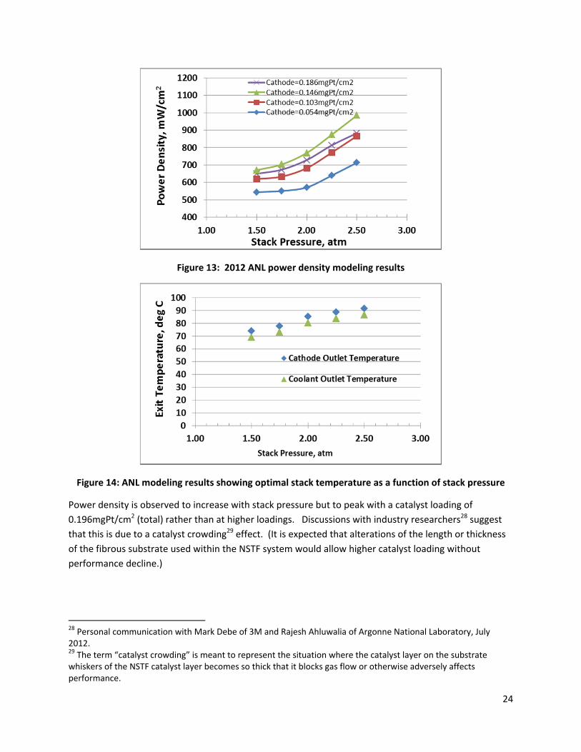
5.1 2012ANLPolarizationOptimizationArgonne National Laboratory updated their modeling results for 2012 to include additional experimental
data using 3M nanostructured thin film (NSTF) catalysts. Discussion with Argonne researchers27
concluded that that the previously‐identified preferred air stoichiometry value of 1.5 was unlikely to
change with the new data. Furthermore, internal ANL modeling optimization was used to determine the
stack operating temperature leading to highest power density. Combining the above factors, and
limiting consideration to 0.676 volts/cell, allowed for simplification of the 2012 ANL polarization
modeling results to a simple function of two variables: power density and temperature results as a
function of pressure and catalyst loading for a fixed air stoichiometry of 1.5. Figure 13 and Figure 14
show the 2012 ANL power density data and optimal stack temperature, respectively. All results assume
0.05mgPt/cm2 anode catalyst loading. Consistent with the 2011 ANL modeling results, the projections
include bipolar plate voltage losses and thus are meant to represent stack‐level performance.
27 Personal communication with Rajesh Ahluwalia, Argonne National Laboratory, July 2012.
Change ReasonChange from
previous value
Cost (500k
systems/year, $/kW)
Final Value for 2011 $47.71
Piping configuration/costing updated and
expandedResponse to industry review $0.76 $48.47
Purge valve upgraded to multi‐function
modelResponse to industry review $0.34 $48.81
Hot pressing process removed and
replaced with crimping roller process
prior to cutting and slitting
Hot pressing incompatible with NSTF
catalyst deposition, new method required
for combining membrane & GDL layers
‐$0.05 $48.76
Ionomer cost curve reductionIonomer cost curve changed to reflect
industry estimated value at high production‐$0.23 $48.53
Pressure, platinum loading, power
density, and temperature updated to
2012 ANL optimization values
New release of ANL optimization curves for
performance parameters$1.83 $50.36
Membrane air humidifier design changeAir humidifier changed to tubular design
(effect offset by ionomer cost reduction)$0.25 $50.61
Gaskets changed from frame gaskets to
sub‐gaskets with screen‐printed seals
New manufacturing process modeled in
response to industry discussions‐$2.14 $48.47
GDL Analysis Replaced with values from
Ballard AnalysisResponse to Tech Team review ‐$1.52 $46.95
Final Value for 2012 ‐$0.76 $46.95
24
Figure 13: 2012 ANL power density modeling results
Figure 14: ANL modeling results showing optimal stack temperature as a function of stack pressure
Power density is observed to increase with stack pressure but to peak with a catalyst loading of
0.196mgPt/cm2 (total) rather than at higher loadings. Discussions with industry researchers28 suggest
that this is due to a catalyst crowding29 effect. (It is expected that alterations of the length or thickness
of the fibrous substrate used within the NSTF system would allow higher catalyst loading without
performance decline.)
28 Personal communication with Mark Debe of 3M and Rajesh Ahluwalia of Argonne National Laboratory, July 2012. 29 The term “catalyst crowding” is meant to represent the situation where the catalyst layer on the substrate whiskers of the NSTF catalyst layer becomes so thick that it blocks gas flow or otherwise adversely affects performance.

25
Based on this polarization performance, a system‐level cost optimization was conducted to select the
operating pressure and catalyst loading that leads to lowest system cost30. Figure 15a reveals that
system cost decreases with increases in operating pressure at all catalyst loadings. Figure 15b reveals
that system cost is minimized at 2.5 atm at a total catalyst loading of 0.196 mgPt/cm2.
Figure 15: Automotive cost optimization to determine optimal operating pressure and catalyst loading, Left: cost vs. pressure, Right: cost vs. Pt loading
Based on this optimization, the 2012 automotive system beginning‐of‐life (BOL) stack design conditions
at peak power are:
0.676 volts/cell
1,456 mA/cm2 current density
984 mW/cm2 power density
2.5 atm stack inlet pressure
87°C (outlet coolant temperature)
0.196 mgPt/cm2 total catalyst loading
30 The cost optimization was conducted at a constant 0.676 volts/cell, 1.5 air stoichiometry, and a stack operating temperature optimized by separate AN modeling (and shown in Figure 14).

26
5.2 IonomerCostReductionFor both the 2011 and 2012 cost analysis, membrane cost was determined by estimating the cost of
Nafion ionomer and then conducting a simplified DFMA‐style analysis on the processing steps required
to transform the ionomer into finished 25.4 micron‐thick membrane. A manufacturer’s quote for Nafion
ionomer (purchase volume dependent) is marked up by 19% to account for markup and a manufacturing
process was modeled to simulate the finished ePTFE‐supported,hydrated PEM membrane. The cost of
ionomer, ePTFE, and manufacturing combine to create a total membrane cost. For the 2012 analysis,
the base ionomer manufacturer’s cost was modified based on input from the DOE and industry Fuel Cell
Technical Team, resulting in a reduced total membrane cost.
SA Cost Model Parameters for Membrane Cost
500k systems/year, 481 MT ionomer/year 2011 Analysis 2012 Analysis
Ionomer, $/kg $149/kg
$9.41/m2
$75/kg
$4.74/m2
ePTFE, $/m2 $8.35
(effective)
$8.35
(effective)
Manufacturing, $/m2 $5.47 $5.09
Total Membrane Cost, $/m2 $23.21 $18.18
Figure 16: SA cost model parameters for membrane cost
The new ionomer cost is based upon a 2010 Dow Chemical reference report on high‐volume ionomer
manufacture31. In this report, ionomer material and manufacturing costs are analyzed at extremely high
volumes: as high as 6,000 MT/year (where ~500MT/year of material is suitable for 500k vehicles/year).
The combination of extremely high production volume and simpler manufacturing process—the industry
report models membrane casting rather than application to an ePTFE substrate—results in reported
costs much lower than calculated by the SA model. The Fuel Cell Tech Team suggested that the
membrane continue to be modeled as an ePTFE‐supported membrane and that we adopt the Dow
ionomer price at plant sizes more in line with expected annual demand. Consequently for the 2012
analysis, a production‐volume‐dependent scaling relationship was derived from the Dow report data
and used to estimate ionomer price at various fuel cell system annual production rates. This ionomer
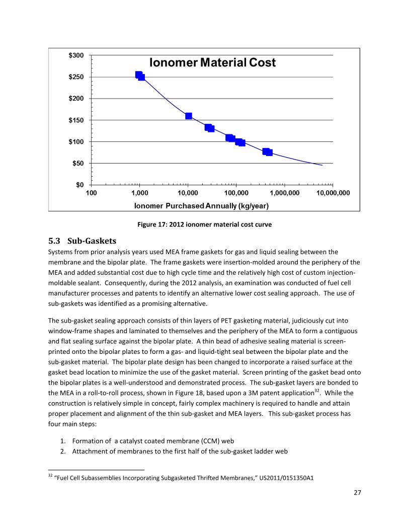
price curve is shown in Figure 17.
31 “High Volume Cost Analysis of Perfluorinated Sulfonic Acid Proton Exchange Membranes,” Tao Xie, Mark F. Mathias, and Susan L. Bell, General Motors, Inc., May 2010
27
Figure 17: 2012 ionomer material cost curve
5.3 Sub‐GasketsSystems from prior analysis years used MEA frame gaskets for gas and liquid sealing between the
membrane and the bipolar plate. The frame gaskets were insertion‐molded around the periphery of the
MEA and added substantial cost due to high cycle time and the relatively high cost of custom injection‐
moldable sealant. Consequently, during the 2012 analysis, an examination was conducted of fuel cell
manufacturer processes and patents to identify an alternative lower cost sealing approach. The use of
sub‐gaskets was identified as a promising alternative.
The sub‐gasket sealing approach consists of thin layers of PET gasketing material, judiciously cut into
window‐frame shapes and laminated to themselves and the periphery of the MEA to form a contiguous
and flat sealing surface against the bipolar plate. A thin bead of adhesive sealing material is screen‐
printed onto the bipolar plates to form a gas‐ and liquid‐tight seal between the bipolar plate and the
sub‐gasket material. The bipolar plate design has been changed to incorporate a raised surface at the
gasket bead location to minimize the use of the gasket material. Screen printing of the gasket bead onto
the bipolar plates is a well‐understood and demonstrated process. The sub‐gasket layers are bonded to
the MEA in a roll‐to‐roll process, shown in Figure 18, based upon a 3M patent application32. While the
construction is relatively simple in concept, fairly complex machinery is required to handle and attain
proper placement and alignment of the thin sub‐gasket and MEA layers. This sub‐gasket process has
four main steps:
1. Formation of a catalyst coated membrane (CCM) web
2. Attachment of membranes to the first half of the sub‐gasket ladder web
32 “Fuel Cell Subassemblies Incorporating Subgasketed Thrifted Membranes,” US2011/0151350A1
28
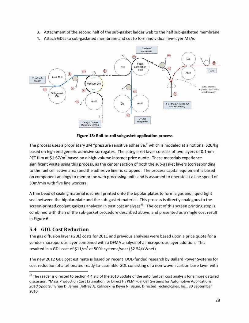
3. Attachment of the second half of the sub‐gasket ladder web to the half sub‐gasketed membrane
4. Attach GDLs to sub‐gasketed membrane and cut to form individual five‐layer MEAs
Figure 18: Roll‐to‐roll subgasket application process
The process uses a proprietary 3M “pressure sensitive adhesive,” which is modeled at a notional $20/kg
based on high end generic adhesive surrogates. The sub‐gasket layer consists of two layers of 0.1mm
PET film at $1.67/m2 based on a high‐volume internet price quote. These materials experience
significant waste using this process, as the center section of both the sub‐gasket layers (corresponding
to the fuel cell active area) and the adhesive liner is scrapped. The process capital equipment is based
on component analogy to membrane web processing units and is assumed to operate at a line speed of
30m/min with five line workers.
A thin bead of sealing material is screen printed onto the bipolar plates to form a gas and liquid tight
seal between the bipolar plate and the sub‐gasket material. This process is directly analogous to the
screen‐printed coolant gaskets analyzed in past cost analyses33. The cost of this screen printing step is
combined with than of the sub‐gasket procedure described above, and presented as a single cost result
in Figure 6.
5.4 GDLCostReductionThe gas diffusion layer (GDL) costs for 2011 and previous analyses were based upon a price quote for a
vendor macroporous layer combined with a DFMA analysis of a microporous layer addition. This
resulted in a GDL cost of $11/m2 at 500k systems/year ($2.54/kWnet).
The new 2012 GDL cost estimate is based on recent DOE‐funded research by Ballard Power Systems for
cost reduction of a teflonated ready‐to‐assemble GDL consisting of a non‐woven carbon base layer with
33 The reader is directed to section 4.4.9.3 of the 2010 update of the auto fuel cell cost analysis for a more detailed discussion. “Mass Production Cost Estimation for Direct H2 PEM Fuel Cell Systems for Automotive Applications: 2010 Update,” Brian D. James, Jeffrey A. Kalinoski & Kevin N. Baum, Directed Technologies, Inc., 30 September 2010.

29
two microporous layers34. The Ballard analysis35 estimates a cost of $4.45/m2 at 10M m2/year
(approximately equivalent to 500k systems/year) and a cost of $56/m2 at less than 100k m2/year
(approximately equivalent to 5k systems/year). Based upon these data points, a learning curve
exponent of 0.6952 was derived and used to estimate the GDL cost at intermediate production rates.
Figure 19 graphically portrays GDL cost used in the analysis as a function of annual GDL production.
Figure 19: GDL cost as a function of production rate
5.5 AdditionalMinorChangesIn addition to the above changes, a series of minor improvements was made to the automotive cost
analysis. Each is briefly described below.
5.5.1 PipingConfigurationUpdateIndustry feedback provided guidance for a more sophisticated analysis of the piping costs. Previous
years’ analyses included piping costs based on a certain percentage of calculated base system costs for
the high temperature cooling, low temperature cooling, and fuel loop subsystems. The new analysis
incorporates a slightly more sophisticated methodology based on the expected type and length of each
piping run and the expected number of fittings, pipe bends, and welds. While this yields only a rough
approximation of piping cost, achieving a more accurate cost analysis would require a detailed layout of
all system components and is beyond the scope of work. Basic assumptions used in the analysis appear
below and in Figure 20, with the piping system cost tabulated in Figure 21.
34 “Reduction in Fabrication Costs of Gas Diffusion Layers,” Jason Morgan, Ballard Power Systems, DOE Annual Merit Review, May 2011. 35 Personal communication with Jason Morgan of Ballard Power Systems, 24 July 2012.
30
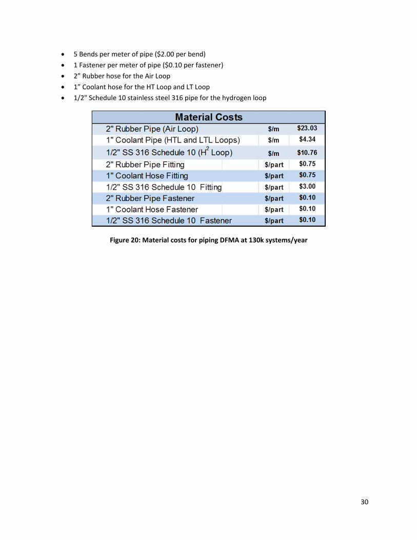
5 Bends per meter of pipe ($2.00 per bend)
1 Fastener per meter of pipe ($0.10 per fastener)
2” Rubber hose for the Air Loop
1” Coolant hose for the HT Loop and LT Loop
1/2" Schedule 10 stainless steel 316 pipe for the hydrogen loop
Figure 20: Material costs for piping DFMA at 130k systems/year
31
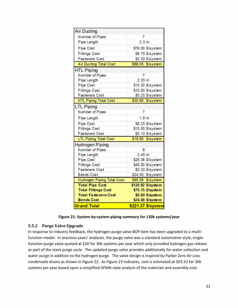
Figure 21: System‐by‐system piping summary for 130k systems/year
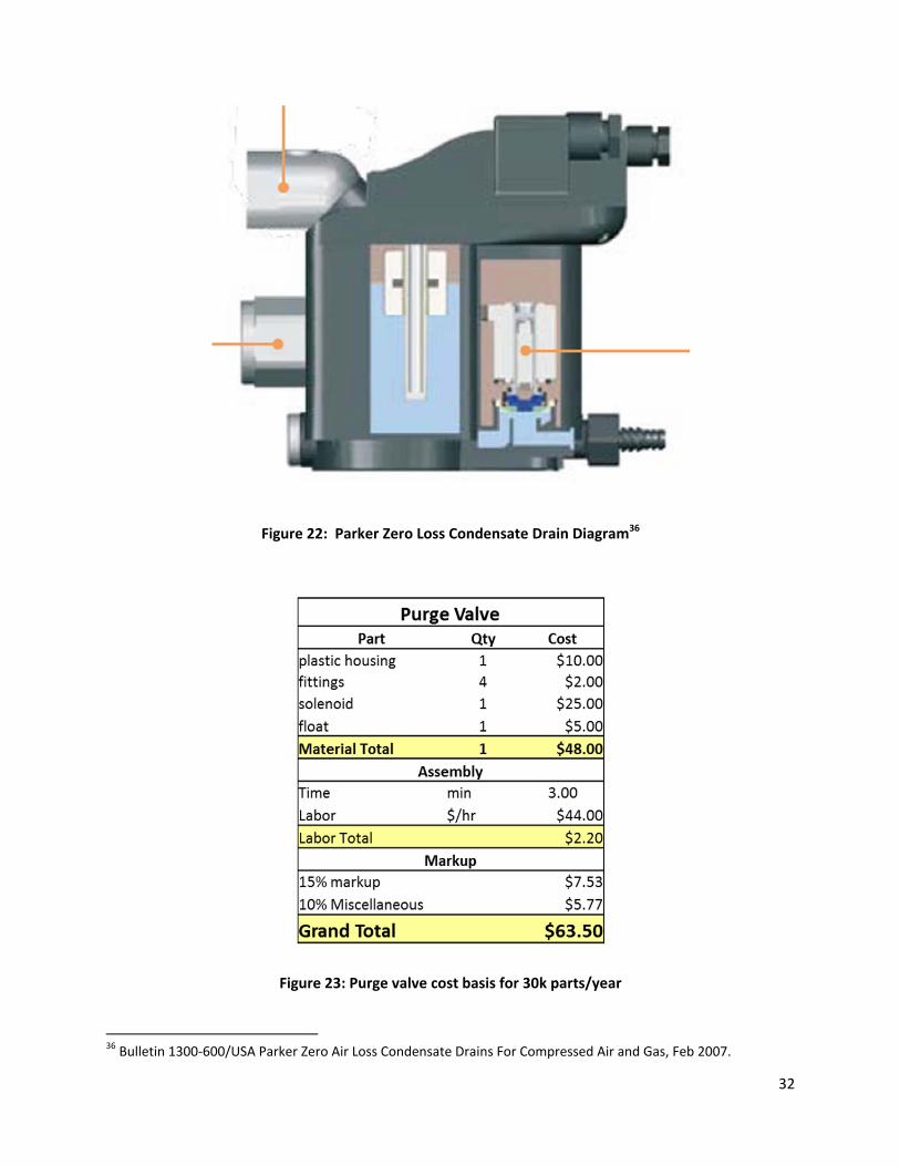
5.5.2 PurgeValveUpgradeIn response to industry feedback, the hydrogen purge valve BOP item has been upgraded to a multi‐
function model. In previous years’ analyses, the purge valve was a standard automotive‐style, single‐
function purge valve quoted at $20 for 30k systems per year which only provided hydrogen gas release
as part of the stack purge cycle. The updated purge valve provides additionally for water collection and
water purge in addition to the hydrogen purge. The valve design is inspired by Parker Zero Air Loss
condensate drains as shown in Figure 22. As Figure 23 indicates, cost is estimated at $63.53 for 30k
systems per year based upon a simplified DFMA‐style analysis of the materials and assembly cost.
32
Figure 22: Parker Zero Loss Condensate Drain Diagram36
Figure 23: Purge valve cost basis for 30k parts/year
36 Bulletin 1300‐600/USA Parker Zero Air Loss Condensate Drains For Compressed Air and Gas, Feb 2007.

33
5.5.3 CrimpingRollerReplacingHotPressingIndustry feedback37 confirmed that the previous modeled procedure of hot pressing the membrane and
GDL to bond the parts was incompatible with the NSTF catalyst layer38. Bonding of the three layers of
the MEA (the catalyst‐coated membrane plus GDL on either side) is desirable for proper alignment of
the parts as well as ease of handling during the MEA gasketing process. Consequently for the 2012 cost
analysis, the layers of the MEA are crimped together periodically along the edges as part of the cutting
and slitting process, to an extent sufficient to hold the assembly together until the sub‐gasketing process
is complete. Cost of the operation is very low, as it merely requires an extra roller assembly in the
cutting and slitting process line.
5.5.4 MembraneAirHumidifierDesignChangeThe cathode membrane humidifier design for 2012 reflects a modified version of the tubular air
humidifiers from previous years’ analysis. This humidifier is based upon a PermaPure tubular membrane
humidifier, resized slightly and incorporating the lower‐cost ionomer (as described in section 5.2).
Future analyses are intended to include a new plate‐frame humidifier modeled after products by Gore,
but that analysis was not completed in time for inclusion in the 2012 analysis. Since plate‐frame
humidifiers may more readily utilize a membrane support layer, thinner membranes are more feasible
than in tubular membrane systems. Water transport is enhanced by a thin membrane, thus plate‐frame
humidifiers are expected to have lower membrane area and a lower overall volume than tubular
humidifier designs. As shown in Figure 24, modeling supports this general observation and confirms
that a planar humidifier system with 25 micron membrane thickness is expected to require substantially
less membrane area than comparable tubular systems. Thus, while the 2012 cost analysis is based on
the larger area tubular humidifier, a size reduction, and potentially cost reduction, is expected next year
when the switch to a plate‐frame humidifier is made.
37 Personal communication with Mark Debe of 3M, November 2011. 38 Previous cost analysis postulated bonding of the GDL and catalyst coated membrane through a hot pressing procedure since the ionomer within the catalyst ink composition could serve as a bonding agent for the GDL. However, there is no ionomer in the NSTF catalyst layer and thus hot pressing would not be effective for NSTF MEA’s.

34
Figure 24: SA vs ANL membrane area projections for tubular and planar humidifier designs
6 BusFuelCellPowerSystemIn addition to the annual cost updated of the automotive fuel cell power system, a transit bus fuel cell
power system was analyzed for the first time as part of the 2012 cost report. The bus power system is
based substantially upon the 2012 automotive technology system, including all of the above listed
changes from the 2011 technology system. The automotive and bus power plants are very similar in
operation with key difference consisting primarily of power level, operating pressure, and catalyst
loading. Section 6.1 below details the key differences between auto and bus power systems. If no
difference is documented in this section, then details of material selection, manufacturing processes,
and system design are assumed not to differ from that of the automotive system.
6.1 BusPowerSystemOverviewandComparisonwithAutomotivePowerSystem
Figure 25 below is a basic comparison summary of the 2012 auto and bus systems. As shown, most
stack mechanical construction and system design features are identical between the bus and
automotive power plants. Primary system differences include:
Use of two ~90kWgross fuel cell stacks to achieve a net system power of 160kWnet (instead
of one ~90kWnet stack for an 80kWnet power level as used in the automotive system)
Higher cell platinum loading (0.4mgPt/cm2 instead of 0.196 mgPt/cm2 as used in the
automotive system)
Differences in cell active area and number of active cells per stack
Higher system voltage (reflecting two stacks electrically in series and the desire to keep
current below 400 amps)

35
Operation at 1.8 atm (instead of 2.5 atm as used in the automotive system)
Use of a twin lobe air compressor (based on an Eaton design) without an exhaust gas
expander (instead of a centrifugal‐compressor/radial‐inflow‐expander based on a
Honeywell design as used in the automotive system)
Reduced stack operating temperature (74°C instead of 87°C as used in the automotive
system)
Increased size in balance of plant components to reflect higher system gross power
Figure 25: Comparison table between 2012 auto and 2012 bus technology systems
2012 Auto Technology
System
2012 Bus Technology
SystemPower Density (mW/cm
2) 984 716
Total Pt loading (mgPt/cm2) 0.196 0.4
Net Power (kWnet) 80 160
Gross Power (kWgross) 88.24 177.10
Operating Pressure (atm) 2.50 1.80
Peak Stack Temp. (°C) 87 74
Active Cells 369 739
Membrane Material Nafion on 25‐micron ePTFE Nafion on 25‐micron ePTFE
Radiator/ Cooling SystemAluminum Radiator,
Water/Glycol Coolant,
DI Filter, Air Precooler
Aluminum Radiator,
Water/Glycol Coolant,
DI Filter, Air Precooler
Bipolar Plates Stamped SS 316L with TreadStone Coating Stamped SS 316L with TreadStone Coating
Air CompressionCentrifugal Compressor,
Radial‐Inflow Expander
Centrifugal Compressor,
Without Expander
Gas Diffusion Layers Carbon Paper Macroporous Layer with
Microporous Layer (Ballard Cost)
Carbon Paper Macroporous Layer with
Microporous Layer (Ballard Cost)
Catalyst Application Nanostructured Thin Film (NSTF) Nanostructured Thin Film (NSTF)
Air Humidification Tubular Membrane Humidifier Tubular Membrane Humidifier
Hydrogen Humidification None None
Exhaust Water Recovery None None
MEA Containment and
Gasketing
Screen Printed Seal on MEA Subgaskets,
GDL crimpted to CCM
Screen Printed Seal on MEA Subgaskets,
GDL crimpted to CCM
Coolant & End GasketsLaser Welded (Cooling),
Screen‐Printed Adhesive Resin (End)
Laser Welded (Cooling),
Screen‐Printed Adhesive Resin (End)
Freeze Protection Drain Water at Shutdown Drain Water at Shutdown
Hydrogen Sensors2 for FC System
1 for Passenger Cabin (not in cost estimate)
1 for Fuel System (not in cost estimate)
2 for FC System
1 for Passenger Cabin (not in cost estimate)
1 for Fuel System (not in cost estimate)
End Plates/
Compression System
Composite Molded End Plates with
Compression Bands
Composite Molded End Plates with Compression
Bands
Stack Conditioning (hrs) 5 5

36
6.2 BusSystemPerformanceParametersThe bus and automotive power systems function in nearly identical fashion but have different power
levels, flow rates, and pressure levels. The following sections describe the sizing methodology and
values for key parameters of the bus power system.
6.2.1 PowerLevelTo provide sufficient power, two 80 kWnet stacks are used in parallel, for a total net electrical power of
160 kW. This number was chosen as an intermediate point in existing bus FC power systems, which
nominally range from 140 kWnet to 190 kWnet electrical. Modeling a system which is an even multiple of
80 kW has the additional advantage of allowing a comparison between a dedicated bus system and a
pair of automotive systems.
6.2.2 PolarizationPerformanceBasisStack performance within the bus systems is based on Argonne National Laboratory modeling of 3M
nanostructured thin film catalyst membrane electrode assembly (MEA) performance. The polarization
curve model used for the bus stacks is the same as used for the automotive system with modification for
different operating conditions and catalyst loading (as discussed below). As understood by the authors,
the two main bus fuel cell power plant suppliers, Ballard Power Systems and UTC Power, use the same
stack construction and MEA composition within their bus power system stacks as they do for their light‐
duty vehicle stacks. Consequently, the same is assumed for this report with the exception of catalyst
loading.
Thus the 2012 bus power system beginning‐of‐life (BOL) stack design conditions at peak power are:
0.676 volts/cell
1,060 mA/cm2 current density
716 mW/cm2 power density
1.8 atm
74°C (outlet coolant temperature)
1.5 air stochiometry
0.4 mgPt/cm2 total catalyst loading (see section 6.2.3)
Discussions with Ballard39 regarding their latest generation40 (HD7) fuel cell stacks suggests an
anticipated bus application design peak power operating point of ~0.69 volts/cell at ~1,100 mA/cm2
yielding a power density of 759mW/cm2 at a stack pressure of 1.8 atm and an ~0.4mgPt/cm2 total
catalyst loading. This operating point is very close to the selected 2012 bus design point and is thus
viewed as validation of the parameter selection.
39 Personal communication, Peter Bach, Ballard Power Systems, October 2012. 40 Ballard FCvelocity HD6 stacks are currently used in Ballard bus fleets. The HD7 stack is the next generation stack, has been extensively tested at Ballard, and is expected to be used in both automotive and bus vehicle power systems next year.
37
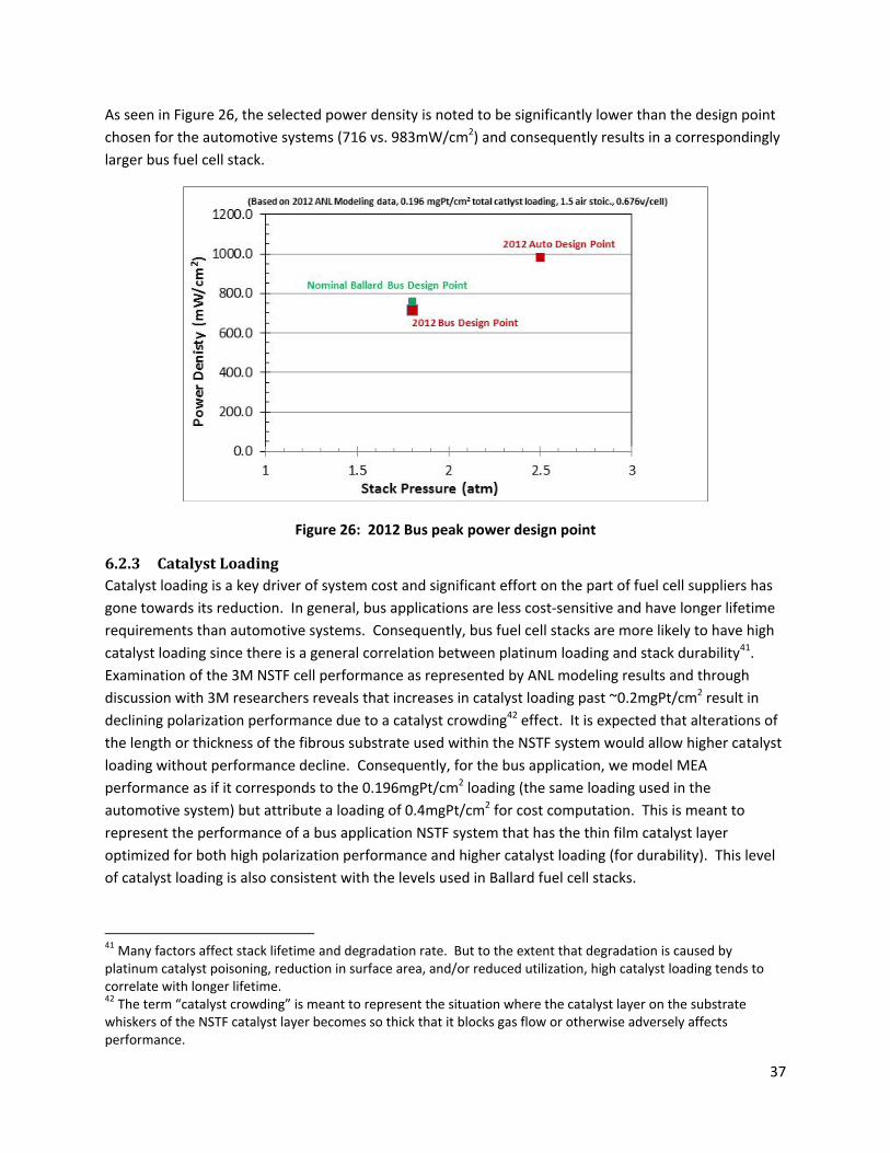
As seen in Figure 26, the selected power density is noted to be significantly lower than the design point
chosen for the automotive systems (716 vs. 983mW/cm2) and consequently results in a correspondingly
larger bus fuel cell stack.
Figure 26: 2012 Bus peak power design point
6.2.3 CatalystLoadingCatalyst loading is a key driver of system cost and significant effort on the part of fuel cell suppliers has
gone towards its reduction. In general, bus applications are less cost‐sensitive and have longer lifetime
requirements than automotive systems. Consequently, bus fuel cell stacks are more likely to have high
catalyst loading since there is a general correlation between platinum loading and stack durability41.
Examination of the 3M NSTF cell performance as represented by ANL modeling results and through
discussion with 3M researchers reveals that increases in catalyst loading past ~0.2mgPt/cm2 result in
declining polarization performance due to a catalyst crowding42 effect. It is expected that alterations of
the length or thickness of the fibrous substrate used within the NSTF system would allow higher catalyst
loading without performance decline. Consequently, for the bus application, we model MEA
performance as if it corresponds to the 0.196mgPt/cm2 loading (the same loading used in the
automotive system) but attribute a loading of 0.4mgPt/cm2 for cost computation. This is meant to
represent the performance of a bus application NSTF system that has the thin film catalyst layer
optimized for both high polarization performance and higher catalyst loading (for durability). This level
of catalyst loading is also consistent with the levels used in Ballard fuel cell stacks.
41 Many factors affect stack lifetime and degradation rate. But to the extent that degradation is caused by platinum catalyst poisoning, reduction in surface area, and/or reduced utilization, high catalyst loading tends to correlate with longer lifetime. 42 The term “catalyst crowding” is meant to represent the situation where the catalyst layer on the substrate whiskers of the NSTF catalyst layer becomes so thick that it blocks gas flow or otherwise adversely affects performance.

38
6.2.4 OperatingPressureAs previously stated, the two main fuel cell bus power plant developers are Ballard Power Systems and
UTC Power. Recent Ballard buses, using their FCvelocity HD6 fuel cell stacks, typically operating at a
stack pressure of ~1.8 atm (at rated power) and do not employ an exhaust gas expander. Recent UTC
Power fuel cell bus power plants, using their porous carbon bipolar plates, typically operate near
ambient pressure. The UTC Power porous carbon plates allow water management within the cell (both
humidification and product water removal) and are a key element of their ability to achieve high
polarization performance at low pressure. The porous carbon bipolar plate construction has not been
cost‐modeled under this effort and it would be inappropriate to postulate the combination of stamped
metal bipolar plate construction with performance of NSTF catalyst MEA at near ambient pressure43.
Consequently, ambient pressure operation is not selected for bus application cost modeling at this time,
although it could be considered in future analysis tasks.
A stack pressure of 1.8 atm is selected as the bus system baseline operating stack pressure at rated
power to reflect the typical operating conditions used by Ballard. An exhaust gas expander is not used
as there is a limited power available from the expansion of gas at this moderate pressure. This
operating point of 1.8 atm without expander is in contrast to the optimized automotive system
operating conditions of 2.5 atm with expander. To further explore the issue of operating pressure, a
sensitivity analysis was conducted. Results are shown report section 10.3.
6.2.5 StackOperatingTemperatureAs in the automotive analysis, the design stack temperature44 at rated (peak) power is determined by
ANL modeling which holistically assesses MEA performance, heat generation, and water management
within the stack. Stack temperature correlates with operating pressure, and stack temperature at rated
power is determined to be 74°C for 1.8 atm. This is a significant reduction from the 87°C temperature of
the automotive system at 2.5 atm.
It is noted that Ballard reports their fuel cell bus stack temperatures at only 60°C. The reasons for this
are several‐fold. First, the system may not typically operate at rated power for long enough times for
stack temperature to rise to its nominal value. This is particularly true for a bus power plant for which,
depending on the bus route, maximum power may be demanded only a low fraction of the time.
Second, various stack and membrane failure mode mechanisms are associated with high temperature.
Thus it may desirable to deliberately limit stack peak temperature as a means to achieving the stack
lifetime goal of >12,000 hours (this is less of a concern for auto applications with lower lifetime
requirements). Thirdly, higher stack temperature reduces the size of the heat rejection temperature
since it increases the temperature difference with the ambient air. For an automobile, volume and
frontal area are at a premium under the hood. Minimizing the size of the radiator is important for the
auto application but is less important for the bus application where radiators may be placed on the roof.
43 This combination is theoretically possible but experimental data is not readily available nor, to the author’s knowledge, have NSTF catalyst MEA parameters been optimized for ambient pressure operation. 44 For modeling purposes, stack operating temperature is defined as the stack exit coolant temperature. Modeling suggests approximately a 10°C temperature difference between coolant inlet and outlet temperatures and the cathode exhaust temperature to be approximately 5°C higher than coolant exit temperature.

39
Thus, there are several good reasons—and fewer disadvantages—in selecting a low operating
temperature for the bus compared to the auto application.
6.2.6 CellActiveAreaandSystemVoltageBecause the system consists of two stacks electrically in series, system voltage has been set to 500V at
design conditions45. This bus voltage represents a doubling relative to the automotive system and is
necessary to maintain the total electrical current below 400 amps. These values are broadly consistent
with the Ballard fuel cell bus voltage range46 of 465 to 730. Specific cell and system parameters are
detailed in Figure 27 for beginning‐of‐life (BOL) conditions.
Parameter Value
Cell Voltage (BOL at rated power) 0.676 V/cell
System Voltage (BOL at rated power) 500 V
Number of Stacks 2
Active Cells per Stack 370
Total Cells per System 740
Active Area per Cell 335 cm2
Stack Gross Power at Rated Power Conditions (BOL)
177 kW
Figure 27: Bus stack parameters
6.3 AirCompressionSystemThe air compression system for the automotive power system is based on a Honeywell‐designed
centrifugal air compressor mated to a radial inflow exhaust gas expander and a 165,000 rpm permanent
magnet motor. However, that compressor‐expander‐motor (CEM) unit is not used for the bus system.
Rather, an Eaton‐style twin vortex, Roots‐type air compressor such as that currently used in Ballard fuel
cell buses is postulated for the cost analysis. A complete DFMA analysis of the Eaton‐style air
compressor has not been conducted but is planned for future analysis. However, it is expected that an
Eaton‐style air compressor will have a cost similar to that of a comparable air flow and pressure ratio
centrifugal compressor unit. Consequently the DFMA cost of a centrifugal compressor47 is used as a
45 For purposed of the system cost analysis, design conditions correlate to rated maximum power at beginning of life. 46 Ballard FCvelocity‐HD6 Spec Sheet. http://www.ballard.com/fuel‐cell‐products/fc‐velocity‐hd6.aspx Accessed 9 October 2012. 47 The 2011 automotive fuel cell analysis conducted by the authors included scaling factors for high speed centrifugal air compressors with integrated permanent magnet motors and controllers, both with and without
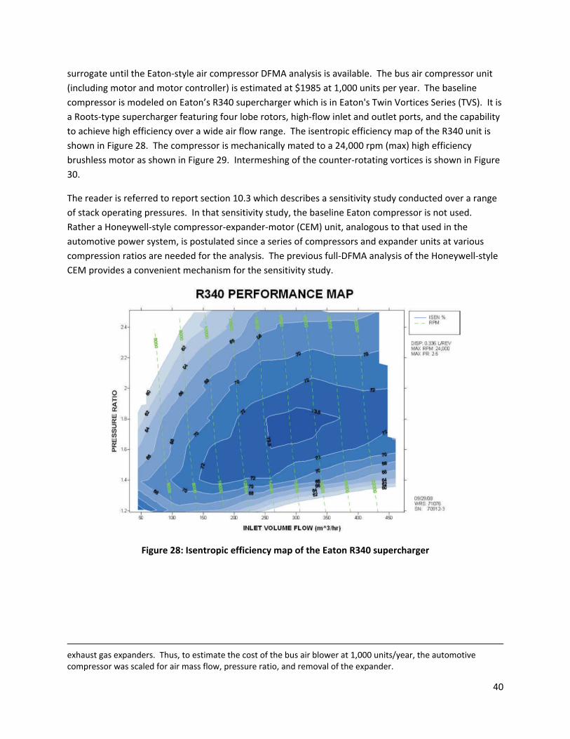
40
surrogate until the Eaton‐style air compressor DFMA analysis is available. The bus air compressor unit
(including motor and motor controller) is estimated at $1985 at 1,000 units per year. The baseline
compressor is modeled on Eaton’s R340 supercharger which is in Eaton's Twin Vortices Series (TVS). It is
a Roots‐type supercharger featuring four lobe rotors, high‐flow inlet and outlet ports, and the capability
to achieve high efficiency over a wide air flow range. The isentropic efficiency map of the R340 unit is
shown in Figure 28. The compressor is mechanically mated to a 24,000 rpm (max) high efficiency
brushless motor as shown in Figure 29. Intermeshing of the counter‐rotating vortices is shown in Figure
30.
The reader is referred to report section 10.3 which describes a sensitivity study conducted over a range
of stack operating pressures. In that sensitivity study, the baseline Eaton compressor is not used.
Rather a Honeywell‐style compressor‐expander‐motor (CEM) unit, analogous to that used in the
automotive power system, is postulated since a series of compressors and expander units at various
compression ratios are needed for the analysis. The previous full‐DFMA analysis of the Honeywell‐style
CEM provides a convenient mechanism for the sensitivity study.
Figure 28: Isentropic efficiency map of the Eaton R340 supercharger
exhaust gas expanders. Thus, to estimate the cost of the bus air blower at 1,000 units/year, the automotive compressor was scaled for air mass flow, pressure ratio, and removal of the expander.
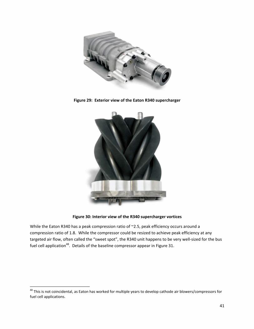
41
Figure 29: Exterior view of the Eaton R340 supercharger
Figure 30: Interior view of the R340 supercharger vortices
While the Eaton R340 has a peak compression ratio of ~2.5, peak efficiency occurs around a
compression ratio of 1.8. While the compressor could be resized to achieve peak efficiency at any
targeted air flow, often called the “sweet spot”, the R340 unit happens to be very well‐sized for the bus
fuel cell application48. Details of the baseline compressor appear in Figure 31.
48 This is not coincidental, as Eaton has worked for multiple years to develop cathode air blowers/compressors for fuel cell applications.
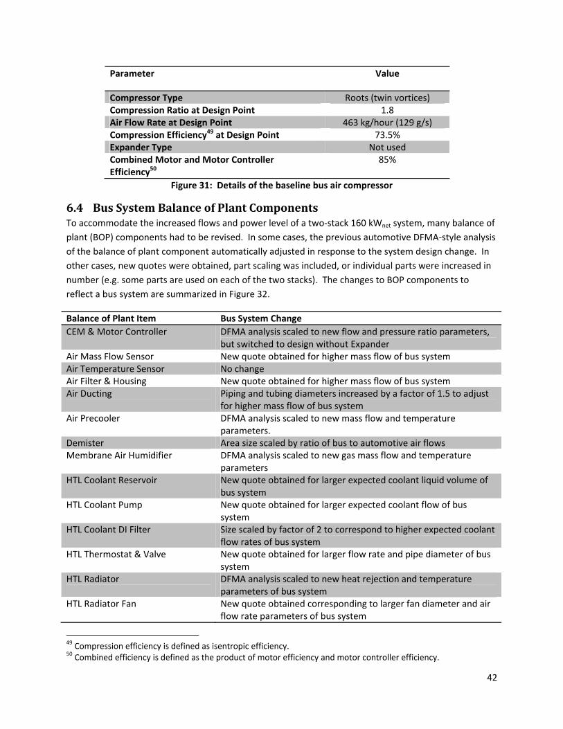
42
Parameter Value
Compressor Type Roots (twin vortices) Compression Ratio at Design Point 1.8 Air Flow Rate at Design Point 463 kg/hour (129 g/s) Compression Efficiency49 at Design Point 73.5% Expander Type Not used Combined Motor and Motor Controller Efficiency50
85%
Figure 31: Details of the baseline bus air compressor
6.4 BusSystemBalanceofPlantComponentsTo accommodate the increased flows and power level of a two‐stack 160 kWnet system, many balance of
plant (BOP) components had to be revised. In some cases, the previous automotive DFMA‐style analysis
of the balance of plant component automatically adjusted in response to the system design change. In
other cases, new quotes were obtained, part scaling was included, or individual parts were increased in
number (e.g. some parts are used on each of the two stacks). The changes to BOP components to
reflect a bus system are summarized in Figure 32.
Balance of Plant Item Bus System Change
CEM & Motor Controller DFMA analysis scaled to new flow and pressure ratio parameters, but switched to design without Expander
Air Mass Flow Sensor New quote obtained for higher mass flow of bus system Air Temperature Sensor No change Air Filter & Housing New quote obtained for higher mass flow of bus system Air Ducting Piping and tubing diameters increased by a factor of 1.5 to adjust
for higher mass flow of bus system Air Precooler DFMA analysis scaled to new mass flow and temperature
parameters. Demister Area size scaled by ratio of bus to automotive air flows Membrane Air Humidifier DFMA analysis scaled to new gas mass flow and temperature
parameters HTL Coolant Reservoir New quote obtained for larger expected coolant liquid volume of
bus system HTL Coolant Pump New quote obtained for larger expected coolant flow of bus
system HTL Coolant DI Filter Size scaled by factor of 2 to correspond to higher expected coolant
flow rates of bus system HTL Thermostat & Valve New quote obtained for larger flow rate and pipe diameter of bus
system HTL Radiator DFMA analysis scaled to new heat rejection and temperature
parameters of bus system HTL Radiator Fan New quote obtained corresponding to larger fan diameter and air
flow rate parameters of bus system
49 Compression efficiency is defined as isentropic efficiency. 50 Combined efficiency is defined as the product of motor efficiency and motor controller efficiency.
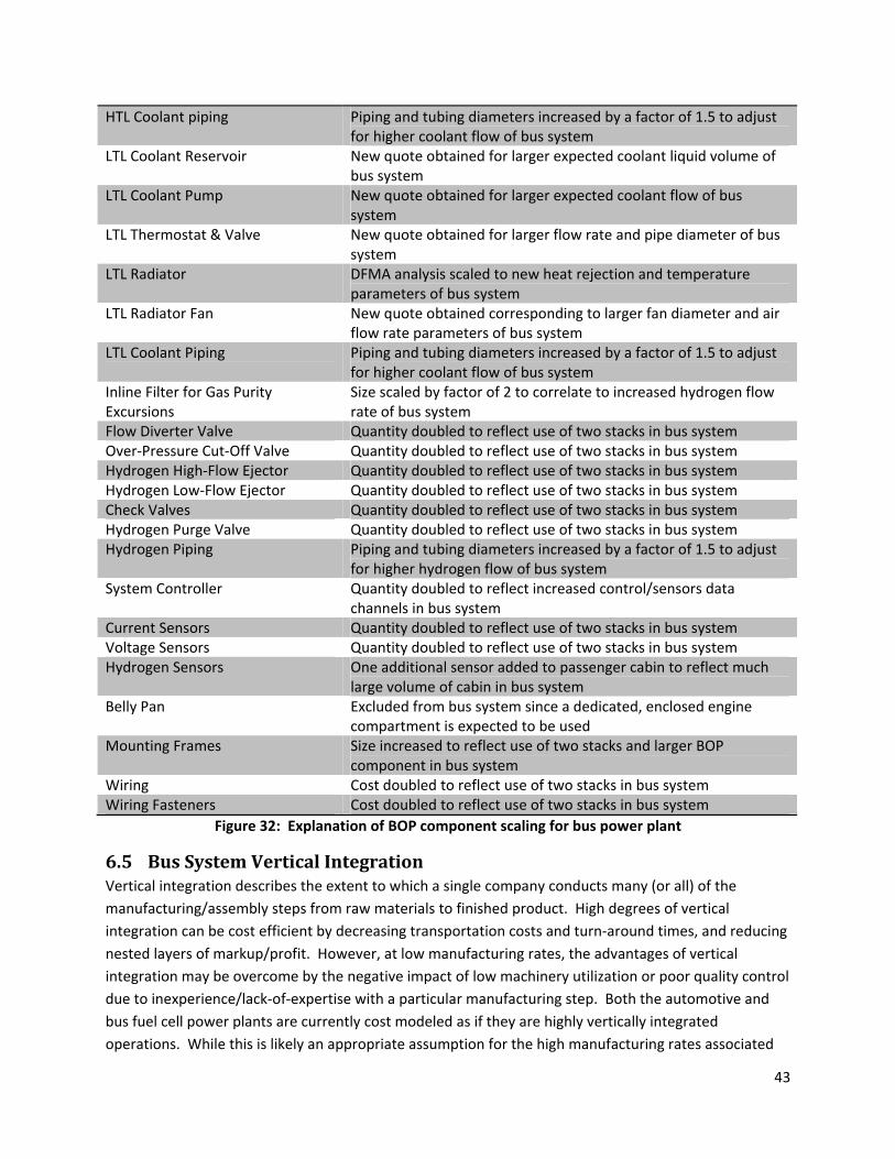
43
HTL Coolant piping Piping and tubing diameters increased by a factor of 1.5 to adjust for higher coolant flow of bus system
LTL Coolant Reservoir New quote obtained for larger expected coolant liquid volume of bus system
LTL Coolant Pump New quote obtained for larger expected coolant flow of bus system
LTL Thermostat & Valve New quote obtained for larger flow rate and pipe diameter of bus system
LTL Radiator DFMA analysis scaled to new heat rejection and temperature parameters of bus system
LTL Radiator Fan New quote obtained corresponding to larger fan diameter and air flow rate parameters of bus system
LTL Coolant Piping Piping and tubing diameters increased by a factor of 1.5 to adjust for higher coolant flow of bus system
Inline Filter for Gas Purity Excursions
Size scaled by factor of 2 to correlate to increased hydrogen flow rate of bus system
Flow Diverter Valve Quantity doubled to reflect use of two stacks in bus system Over‐Pressure Cut‐Off Valve Quantity doubled to reflect use of two stacks in bus system Hydrogen High‐Flow Ejector Quantity doubled to reflect use of two stacks in bus system Hydrogen Low‐Flow Ejector Quantity doubled to reflect use of two stacks in bus system Check Valves Quantity doubled to reflect use of two stacks in bus system Hydrogen Purge Valve Quantity doubled to reflect use of two stacks in bus system Hydrogen Piping Piping and tubing diameters increased by a factor of 1.5 to adjust
for higher hydrogen flow of bus system System Controller Quantity doubled to reflect increased control/sensors data
channels in bus system Current Sensors Quantity doubled to reflect use of two stacks in bus system Voltage Sensors Quantity doubled to reflect use of two stacks in bus system Hydrogen Sensors One additional sensor added to passenger cabin to reflect much
large volume of cabin in bus system Belly Pan Excluded from bus system since a dedicated, enclosed engine
compartment is expected to be used Mounting Frames Size increased to reflect use of two stacks and larger BOP
component in bus system Wiring Cost doubled to reflect use of two stacks in bus system Wiring Fasteners Cost doubled to reflect use of two stacks in bus system
Figure 32: Explanation of BOP component scaling for bus power plant
6.5 BusSystemVerticalIntegrationVertical integration describes the extent to which a single company conducts many (or all) of the
manufacturing/assembly steps from raw materials to finished product. High degrees of vertical
integration can be cost efficient by decreasing transportation costs and turn‐around times, and reducing
nested layers of markup/profit. However, at low manufacturing rates, the advantages of vertical
integration may be overcome by the negative impact of low machinery utilization or poor quality control
due to inexperience/lack‐of‐expertise with a particular manufacturing step. Both the automotive and
bus fuel cell power plants are currently cost modeled as if they are highly vertically integrated
operations. While this is likely an appropriate assumption for the high manufacturing rates associated

44
with automobiles, it is more uncertain as applied to buses. Consequently, the issue of bus fuel cell
power system vertical integration will be revisited in future analyses.
7 CapitalandQualityControlEquipmentQuality control was introduced to the cost model beginning in the 2011 Report. Thus, the current auto
and bus technology cost models include the cost of quality control equipment. The reader is referred to
the 2011 Report for a detailed listing of quality control equipment for each manufacturing process.
For this effort, a complete review of the 2011 quality control was performed by team partners at NREL
but was completed too late for changes to be implemented in the 2012 analysis. However, the review
and suggestions will allow for further iteration and improved accuracy in modeling quality control
equipment in the 2013 update to this modeling effort.
8 AutomotiveSimplifiedCostModelFunctionA simplified cost model to estimate the total automotive power system cost at 500,000 systems/year
production rate is shown in Figure 33. The simplified model is based on key systems parameters likely to
be readily available to the interested party and is generated from regression analysis of many runs of
the full DFMA‐style cost model. The simplified model allows a quick and convenient method to estimate
system cost at off‐baseline conditions.
A simplified cost model to estimate the total automotive power system cost at 500,000 systems/year
production rate is shown in Figure 33. The simplified model splits the total system cost into five
subcategories (stack cost, thermal management cost, water management cost, air management cost,
and balance of plant cost) and generates a scaling equation for each one. The scaling equations for
individual cost components are based on key system parameters for that component that are likely to
be of interest when studying system scaling. The curves are generated by regression analysis of many
runs of the full DFMA‐style cost model over many variations of the chosen parameters. The simplified
model allows a quick and convenient method to estimate system cost at off‐baseline conditions.
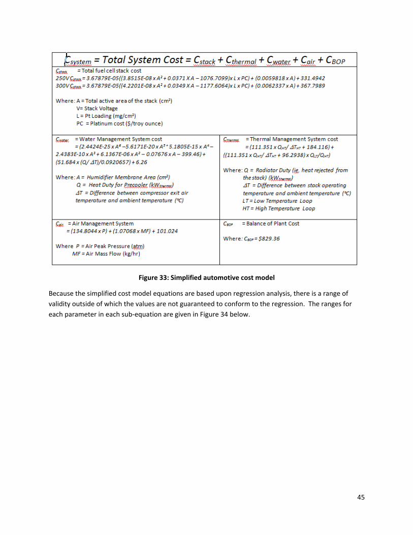
45
Figure 33: Simplified automotive cost model
Because the simplified cost model equations are based upon regression analysis, there is a range of
validity outside of which the values are not guaranteed to conform to the regression. The ranges for
each parameter in each sub‐equation are given in Figure 34 below.
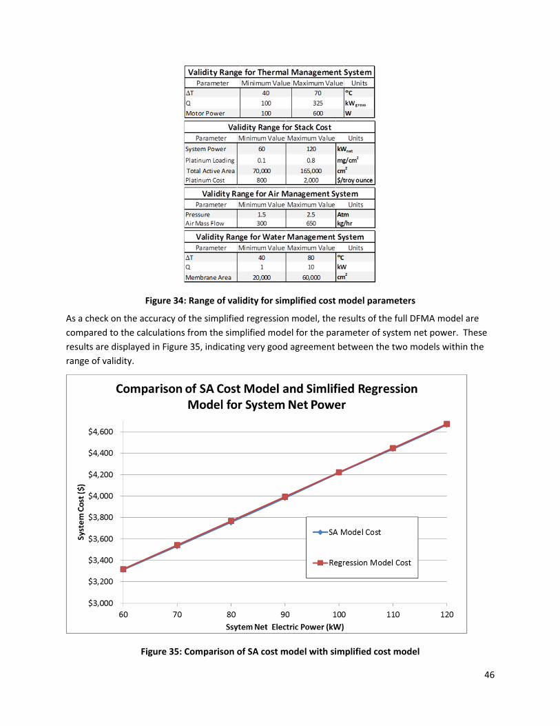
46
Figure 34: Range of validity for simplified cost model parameters
As a check on the accuracy of the simplified regression model, the results of the full DFMA model are
compared to the calculations from the simplified model for the parameter of system net power. These
results are displayed in Figure 35, indicating very good agreement between the two models within the
range of validity.
Figure 35: Comparison of SA cost model with simplified cost model
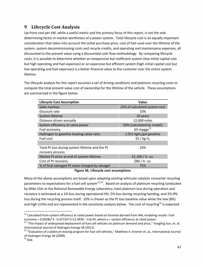
47
9 LifecycleCostAnalysisUp‐front cost per kW, while a useful metric and the primary focus of this report, is not the sole
determining factor in market worthiness of a power system. Total lifecycle cost is an equally important
consideration that takes into account the initial purchase price, cost of fuel used over the lifetime of the
system, system decommissioning costs and recycle credits, and operating and maintenance expenses, all
discounted to the present value using a discounted cash flow methodology. By comparing lifecycle
costs, it is possible to determine whether an inexpensive but inefficient system (low initial capital cost
but high operating and fuel expenses) or an expensive but efficient system (high initial capital cost but
low operating and fuel expenses) is a better financial value to the customer over the entire system
lifetime.
The lifecycle analysis for this report assumes a set of driving conditions and platinum recycling costs to
compute the total present value cost of ownership for the lifetime of the vehicle. These assumptions
are summarized in the figure below.
Lifecycle Cost Assumption Value
Sales markup 25% of calculated system cost Discount rate 10% System lifetime 10 years Distance driven annually 12,000 miles System efficiency at rated power 50% (calculated by model) Fuel economy 65 mpgge51 Hydrogen to gasoline heating value ratio 1.011 kgH2/gal gasoline Fuel cost $5 / kg H2 Total Pt loss during system lifetime and the Pt recovery process
10%
Market Pt price at end of system lifetime $1,100 / tr. oz. Cost of Pt recovery $80 / tr. oz. % of final salvaged Pt value charged by salvager 75%
Figure 36. Lifecycle cost assumptions
Many of the above assumptions are based upon adapting existing vehicular catalytic converter recycling
parameters to expectations for a fuel cell system,52,53. Based on analysis of platinum recycling conducted
by Mike Ulsh at the National Renewable Energy Laboratory, total platinum loss during operation and
recovery is estimated at a 1% loss during operational life, 5% loss during recycling handing, and 2%‐9%
loss during the recycling process itself. 10% is chosen as the Pt loss baseline value while the low (8%)
and high (15%) end are represented in the sensitivity analysis below. The cost of recycling54 is expected
51 Calculated from system efficiency at rated power based on formula derived from ANL modeling results: Fuel economy = 0.0028x^3 ‐ 0.3272X^2+12.993X ‐ 116.45, where x = system efficiency at rated power. 52 “The impact of widespread deployment of fuel cell vehicles on platinum demand and price,” Yongling Sun, et. al. International Journal of Hydrogen Energy 36 (2011). 53 “Evaluation of a platinum leasing program for fuel cell vehicles,” Matthew A. Kromer et. al., International Journal of Hydrogen Energy 34 (2009). 54 Ibid.

48
to range between $75 and $90 per troy ounce of recovered platinum. However this is only the cost
incurred by running the actual recycle process. In addition, there are supply chain costs as the capturer
or salvager performing the recycle retains a portion of the value of the recovered metal. This is
expected to be about 70%‐75% of the total value of recycled platinum55. A sensitivity analysis is
conducted for cases where the salvager captures only 35% of the recovered value. Finally, due to
platinum market price volatility, it is unlikely that Pt price will be exactly the same at system purchase as
it is 10 years later at time of recycle. Consequently, for purposes of the baseline LCC analysis, the price
of platinum is held constant at the purchase price used for the catalyst within a new vehicle ($1,100 / tr.
oz.), and sensitivity analysis is conducted for a future56 higher Pt price ($2300/tr. oz. at end of life).
Under these assumptions, a basic set of cost results is calculated and displayed in Figure 37. Note that
these results are only computed for the automotive system and not for the bus system; bus drive cycle
and use patterns are vastly different from the average personal vehicle. Additional modeling and
research is required to develop a representative equation governing the fuel economy of full‐service
transit buses.
Figure 37: Auto LCC results for the baseline assumptions
The variation of lifecycle cost with system efficiency was studied in order to examine the trade‐offs
between low efficiency (higher operating costs but lower initial capital costs) and high efficiency (lower
operating costs but higher initial capital costs) systems. Because the ANL 2012 performance
optimization data was only obtained for 0.676 V/cell (and hence 55% fuel cell stack efficiency), the
system performance as a function of cell voltage first had to be postulated. This was done by examining
the shape of the polarization curve of 2011 ANL polarization data at 2012 operating conditions, and then
shifting the curve appropriately for the changes between 2011 and 2012. The resulting comparison
graph is shown Figure 38. The 2011 and 2012 ANL performance estimates (using 2012 conditions) are
very similar. Consequently there is high confidence in the postulated 2012 polarization curve.
55 Ibid. 56 Platinum price is considered more likely to increase in the future rather than decrease. Consequently, the future price of Pt is based on the current Pt market price (~$1700/tr. oz) plus a $60/tr. oz. per year increase, resulting in a $2300/tr. oz. price after 10 years.
Annual Production Rate 1,000 10,000 30,000 80,000 130,000 500,000System Cost $17,403.83 $6,725.10 $5,668.96 $4,733.49 $4,410.57 $3,756.18
System Price (After Markup) $21,754.79 $8,406.38 $7,086.20 $5,916.86 $5,513.21 $4,695.23
Annual Fuel Cost $933.00 $933.00 $933.00 $933.00 $933.00 $933.00
Lifecycle Fuel Cost $5,732.88 $5,732.88 $5,732.88 $5,732.88 $5,732.88 $5,732.88
Net Present Value of Recoverable Pt in System at
End of System Lifetime$200.05 $200.05 $200.05 $200.05 $200.05 $200.05
Final Pt Net Present Value Recovered $50.01 $50.01 $50.01 $50.01 $50.01 $50.01
Total Lifecycle Cost $27,437.66 $14,089.25 $12,769.07 $11,599.73 $11,196.08 $10,378.10
Total Lifecycle Cost ($/mile) $0.229 $0.117 $0.106 $0.097 $0.093 $0.086
2012 Auto System Life Cycle Costs

49
Figure 38: Polarization curves for efficiency sensitivity analysis
With this relationship, it is possible to calculate the variation in life cycle cost contributors over a range
of efficiencies. These results are shown below. Figure 39 displays the results for the total lifecycle cost
as well as its component costs on an absolute scale. Note that the total lifecycle cost (i.e. the present
value of the 10 year expenses of the power system) is expressed as a $/mile value for easy comparison
with internal combustion engine vehicle LCC analyses. Figure 40 shows a zoomed‐in look at the total
cost, indicating a minimum total life cycle cost at the baseline system value of 50% system efficiency
(corresponding to 55% fuel cell stack efficiency and cell voltage of 0.676 V/cell). However, the range of
LCC cost variation over the range of system efficiencies examined is quite small, indicating that LCC is
generally insensitive to system efficiency.

50
Figure 39: Life cycle cost components vs. fuel cell efficiency for 500k automobile systems/ year
Figure 40: Life cycle cost vs. fuel cell efficiency for 500k automobile systems/year
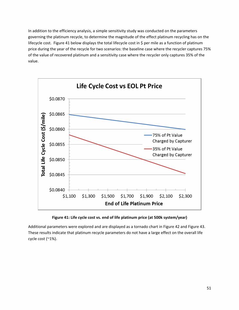
51
In addition to the efficiency analysis, a simple sensitivity study was conducted on the parameters
governing the platinum recycle, to determine the magnitude of the effect platinum recycling has on the
lifecycle cost. Figure 41 below displays the total lifecycle cost in $ per mile as a function of platinum
price during the year of the recycle for two scenarios: the baseline case where the recycler captures 75%
of the value of recovered platinum and a sensitivity case where the recycler only captures 35% of the
value.
Figure 41: Life cycle cost vs. end of life platinum price (at 500k system/year)
Additional parameters were explored and are displayed as a tornado chart in Figure 42 and Figure 43.
These results indicate that platinum recycle parameters do not have a large effect on the overall life
cycle cost (~1%).

52
Figure 42: Life cycle cost tornado chart parameters
Figure 43: Life cycle cost tornado chart (at 500k systems/year)
Parameter Units
Low
Value of
Variable
Base
Value
High Value
of Variable
Salvage Value Charged 35% 75% 75%
Price at Recovery $1,100 $1,100 $2,300
Total Pt Loss 8% 10% 15%
Cost of Recovery $70 $80 $90
Life Cycle Cost ($/mile), 500,000 sys/year
2012 Auto System LCC $0.08648
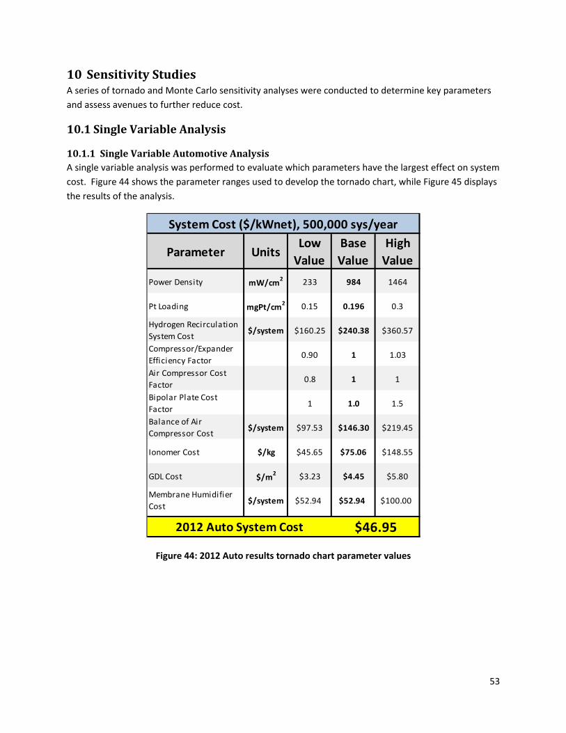
53
10 SensitivityStudiesA series of tornado and Monte Carlo sensitivity analyses were conducted to determine key parameters
and assess avenues to further reduce cost.
10.1 SingleVariableAnalysis
10.1.1 SingleVariableAutomotiveAnalysisA single variable analysis was performed to evaluate which parameters have the largest effect on system
cost. Figure 44 shows the parameter ranges used to develop the tornado chart, while Figure 45 displays
the results of the analysis.
Figure 44: 2012 Auto results tornado chart parameter values
Parameter UnitsLow
Value
Base
Value
High
Value
Power Density mW/cm2 233 984 1464
Pt Loading mgPt/cm2 0.15 0.196 0.3
Hydrogen Recirculation
System Cost$/system $160.25 $240.38 $360.57
Compressor/Expander
Efficiency Factor0.90 1 1.03
Air Compressor Cost
Factor0.8 1 1
Bipolar Plate Cost
Factor1 1.0 1.5
Balance of Air
Compressor Cost$/system $97.53 $146.30 $219.45
Ionomer Cost $/kg $45.65 $75.06 $148.55
GDL Cost $/m2 $3.23 $4.45 $5.80
Membrane Humidifier
Cost$/system $52.94 $52.94 $100.00
System Cost ($/kWnet), 500,000 sys/year
2012 Auto System Cost $46.95
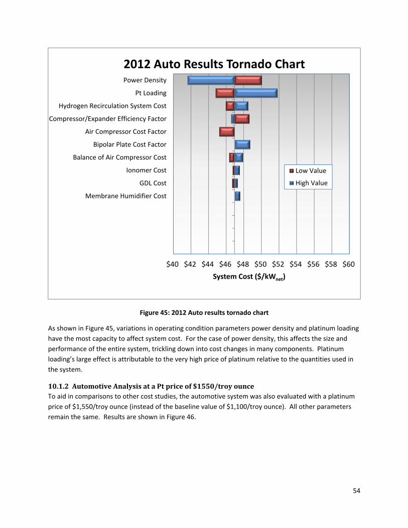
54
Figure 45: 2012 Auto results tornado chart
As shown in Figure 45, variations in operating condition parameters power density and platinum loading
have the most capacity to affect system cost. For the case of power density, this affects the size and
performance of the entire system, trickling down into cost changes in many components. Platinum
loading’s large effect is attributable to the very high price of platinum relative to the quantities used in
the system.
10.1.2 AutomotiveAnalysisataPtpriceof$1550/troyounceTo aid in comparisons to other cost studies, the automotive system was also evaluated with a platinum
price of $1,550/troy ounce (instead of the baseline value of $1,100/troy ounce). All other parameters
remain the same. Results are shown in Figure 46.
$40 $42 $44 $46 $48 $50 $52 $54 $56 $58 $60
Power Density
Pt Loading
Hydrogen Recirculation System Cost
Compressor/Expander Efficiency Factor
Air Compressor Cost Factor
Bipolar Plate Cost Factor
Balance of Air Compressor Cost
Ionomer Cost
GDL Cost
Membrane Humidifier Cost
0
0
0
System Cost ($/kWnet)
2012 Auto Results Tornado Chart
Low Value
High Value

55
Figure 46: Detailed system cost for the 2012 automotive technology system with a Pt price of $1,550/troy ounce
10.1.3 SingleVariableBusAnalysisA single variable analysis of the bus system was also conducted. Because 1,000 systems/year is the only
manufacturing rate analyzed for the bus, the cost at this rate is the cost considered.
Figure 47: 2012 Bus results tornado chart parameter values
Annual Production Rate 1,000 10,000 30,000 80,000 130,000 500,000
System Net Electric Power (Output) 80 80 80 80 80 80
System Gross Electric Power (Output) 88.24 88.24 88.24 88.24 88.24 88.24
Fuel Cell Stacks $12,030.41 $3,595.59 $2,648.64 $2,262.84 $2,143.33 $1,912.74
Balance of Plant $5,527.67 $3,328.28 $3,220.79 $2,671.34 $2,468.38 $2,044.57
System Assembly & Testing $145.13 $100.62 $98.90 $98.69 $98.24 $98.25
Total System Cost ($) $17,703.21 $7,024.49 $5,968.34 $5,032.87 $4,709.94 $4,055.56
Total System Cost ($/kWnet) $221.29 $87.81 $74.60 $62.91 $58.87 $50.69
Total System Cost ($/kWgross) $200.62 $79.60 $67.64 $57.03 $53.38 $45.96
2012 Automotive System
Parameter UnitsLow
Value
Base
Value
High
Value
Power Density mW/cm2 500 716 984
Pt Loading mgPt/cm2 0.2 0.4 0.8
GDL Cost $/m2 $74.10 $115.87 $151.02
Bipolar Plate & Coating Cost Factor 1 1 2
Air Compressor Cost Factor 0.8 1 1
Membrane Humidifier Cost $/system $382.83 $765.66 $1,531.32
Ionomer Cost $/kg $45.65 $204.00 $500.00
Hydrogen Recirculation System Cost $/system $321.00 $641.99 $1,283.98
Balance of Air Compressor Cost $/system $185.25 $370.50 $741.00
Product of Compressor / Motor &
Motor Controller Efficiencies% 51% 59% 64%
System Cost ($/kWnet), 1,000 sys/year
2012 Bus System Cost $190.69

56
Figure 48: 2012 Bus results tornado chart
As with the automotive system, power density and platinum loading have the largest potential to vary
system cost. Unlike the automotive system, however, there is also a large cost variation potential to be
found in GDL and bipolar plate cost variations. This is because at lower manufacturing rate, the cost of
manufactured component items is high and subject to large changes in cost relative to components
manufactured at high volume, as in the automotive case.
10.2 MonteCarloAnalysisIn order to evaluate the bounds for the likely variation in final results, a Monte Carlo analysis was
conducted for both the automotive and bus results. With these results, it is possible to examine the
probability of various model outcomes based upon assumed probability functions for selected inputs.
For all inputs, triangular distributions were chosen with a minimum, maximum, and most likely value.
The most likely value is the result used in the baseline cost analysis, while the maximum and minimum
were chosen with the input of the Fuel Cell Tech Team to reflect likely real‐world bounds for 2012.
$160 $170 $180 $190 $200 $210 $220 $230
Power Density
Pt Loading
GDL Cost
Bipolar Plate & Coating Cost Factor
Air Compressor Cost Factor
Membrane Humidifier Cost
Ionomer Cost
Hydrogen Recirculation System Cost
Balance of Air Compressor Cost
Product of Compressor / Motor & MotorController Efficiencies
System Cost ($/kWnet)
2012 Bus Results Tornado Chart
Low Value
High Value
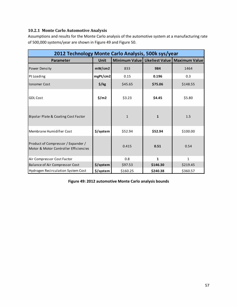
57
10.2.1 MonteCarloAutomotiveAnalysisAssumptions and results for the Monte Carlo analysis of the automotive system at a manufacturing rate
of 500,000 systems/year are shown in Figure 49 and Figure 50.
Figure 49: 2012 automotive Monte Carlo analysis bounds
Unit Minimum Value Likeliest Value Maximum Value
mW/cm2 833 984 1464
mgPt/cm2 0.15 0.196 0.3
$/kg $45.65 $75.06 $148.55
$/m2 $3.23 $4.45 $5.80
1 1 1.5
$/system $52.94 $52.94 $100.00
0.415 0.51 0.54
0.8 1 1
$/system $97.53 $146.30 $219.45
$/system $160.25 $240.38 $360.57
GDL Cost
Parameter
Power Density
Pt Loading
Ionomer Cost
2012 Technology Monte Carlo Analysis, 500k sys/year
Air Compressor Cost Factor
Balance of Air Compressor Cost
Hydrogen Recirculation System Cost
Bipolar Plate & Coating Cost Factor
Membrane Humidifier Cost
Product of Compressor / Expander /
Motor & Motor Controller Efficiencies

58
Figure 50: 2012 automotive Monte Carlo analysis results
Monte Carlo analysis indicates that the middle 90% probability range of cost is between $46.21/kWnet
and $52.20/kWnet for the automotive system at 500,000 systems/year.
10.2.2 MonteCarloBusAnalysisAssumptions and results for the Monte Carlo analysis of the bus system at a manufacturing rate of 1,000
systems/year are shown in Figure 51 and Figure 52Figure 50.
5.0% 90.0% 5.0%
$46.21 $52.20
System Cost ($/kWnet)
0.00
0.05
0.10
0.15
0.20
0.25
500k systems/year, $/kWnet
500k systems/year, $/kWnet
Minimum $43.30Maximum $55.89Mean $49.06Std Dev $1.83Values 20000

59
Figure 51: 2012 bus Monte Carlo analysis bounds
Figure 52: 2012 bus Monte Carlo analysis results
Unit Minimum Value Likeliest Value Maximum Value
mW/cm2 500 716 984
mgPt/cm2 0.2 0.4 0.8
$/kg $45.65 $204.00 $500.00
$/m2 $84.10 $115.87 $151.02
1 1 2
$/system $382.83 $765.66 $1,531.32
0.510 0.588 0.64
0.8 1 1.5
$/system $185.25 $370.50 $741.00
$/system $321.00 $641.99 $1,283.98
GDL Cost
Parameter
Power Density
Pt Loading
Ionomer Cost
2012 Bus Technology Monte Carlo Analysis, 1k sys/year
Air Compressor Cost Factor
Balance of Air Compressor Cost
Hydrogen Recirculation System Cost
Bipolar Plate & Coating Cost Factor
Membrane Humidifier Cost
Product of Compressor / Expander /
Motor & Motor Controller Efficiencies
5.0% 90.0% 5.0%
$179.64 $233.20
$140
$160
$180
$200
$220
$240
$260
$280
System Cost
0.000
0.005
0.010
0.015
0.020
0.025
0.030
Prob
abili
ty D
ensi
ty
1000 systems/year, $/kWnet
1,000 $/kWnet
Minimum $159.36Maximum $276.08Mean $203.92Std Dev $16.23Values 20000

60
Monte Carlo analysis indicates that the middle 90% probability range of cost is between $179.64/kWnet
and $233.20/kWnet for the bus system at 1,000 systems/year.
10.3 AnalysisofBusOperationatHigherPressurewithanExhaustGasExpander
The baseline bus power system operates at 1.8 atm under design conditions with this pressurization
level chosen to match current Ballard bus fleet practice. However, the automotive power system
pressure is selected not by imitation of current practice but by cost optimization. Consequently, a
similar system level cost optimization was conducted for the bus system to determine the operating
pressure (and presence or absence of an expander) that leads to lowest system cost. Results of the
optimization are shown in Figure 53 and reveal that a 2.5 atm pressure with an exhaust gas expander
results in the lowest system cost. However, the difference between the compressor‐only and the
compressor‐with‐expander case is surprisingly small, suggesting that the compressor‐only case may
reasonably be chosen since it is mechanically less complex. Both curves have a moderate slope,
suggesting that increased pressure is preferred as the higher power density afforded by increased
pressure more than compensates for the higher system gross power resulting from higher compression
parasitics. The optimization is based on 2012 ANL stack modeling which is limited to 2.5 atm. However
both curves are observed to be leveling out with increasing pressure, suggesting that only minor gains
may be attained at pressure above 2.5 atm. Overall, the sensitivity analysis suggests that system cost
might be reduced by ~9% (from $191/kWnet to $174/kWnet) by increasing pressure from 1.8 atm to 2.5
atm. However, this cost improvement must be balanced against several factors not reflected in the
analysis: potential for increased cell gas leakage, enhanced stack compression requirements, and
potential difficulties/risks in handling the higher air temperatures resulting from higher compression
ratio.
(Note that stack polarization performance for the optimization is based on 2012 ANL modeling of 3M
NSTF MEA performance for 0.196mgPt/cm2 but with catalyst loading increased to 0.4mgPt/cm2 for cost
purposes only. This is to model an optimized high‐durability and high‐performance MEA suitable for bus
application. Durability and performance at this loading has not been experimentally demonstrated.)
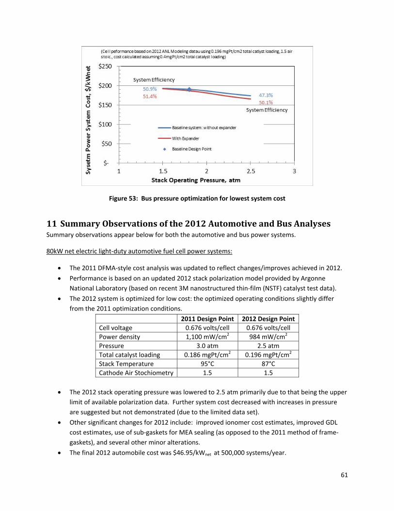
61
Figure 53: Bus pressure optimization for lowest system cost
11 SummaryObservationsofthe2012AutomotiveandBusAnalysesSummary observations appear below for both the automotive and bus power systems.
80kW net electric light‐duty automotive fuel cell power systems:
The 2011 DFMA‐style cost analysis was updated to reflect changes/improves achieved in 2012.
Performance is based on an updated 2012 stack polarization model provided by Argonne
National Laboratory (based on recent 3M nanostructured thin‐film (NSTF) catalyst test data).
The 2012 system is optimized for low cost: the optimized operating conditions slightly differ
from the 2011 optimization conditions.
2011 Design Point 2012 Design Point
Cell voltage 0.676 volts/cell 0.676 volts/cell
Power density 1,100 mW/cm2 984 mW/cm2
Pressure 3.0 atm 2.5 atm
Total catalyst loading 0.186 mgPt/cm2 0.196 mgPt/cm2
Stack Temperature 95°C 87°C
Cathode Air Stochiometry 1.5 1.5
The 2012 stack operating pressure was lowered to 2.5 atm primarily due to that being the upper
limit of available polarization data. Further system cost decreased with increases in pressure
are suggested but not demonstrated (due to the limited data set).
Other significant changes for 2012 include: improved ionomer cost estimates, improved GDL
cost estimates, use of sub‐gaskets for MEA sealing (as opposed to the 2011 method of frame‐
gaskets), and several other minor alterations.
The final 2012 automobile cost was $46.95/kWnet at 500,000 systems/year.
62
Monte Carlo analysis yields middle 90% probability bounds of $46.21/kWnet‐$52.20/kWnet for the
automotive system.
The 2012 automobile system balance of plant (BOP) components represent 54% of the overall
system cost.
160kW Bus fuel cell power systems:
Stack performance is based on 2012 stack polarization model provided by Argonne National Laboratory
(the same data set used for the automotive system) but with total Pt loading raised from 0.196
mgPt/cm2 to 0.4mgPt/cm2 to reflect the longer durability requirements of the bus application.
Power density, voltage, pressure, and catalyst loading of the selected system design point is
consistent with the actual operating conditions of Ballard fuel cell buses currently in service.
Approximate Ballard Bus Design Point
2012 Bus Design Point
Cell voltage ~0.69 volts/cell 0.676 volts/cell
Power density ~759 mW/cm2 716 mW/cm2
Pressure ~1.8 atm 1.8 atm
Total catalyst loading ~0.4 mgPt/cm2 0.4 mgPt/cm2
Stack Temperature ~60°C 74°C
Cathode Air Stochiometry 1.5‐2.0 1.5
Primary differences between the bus and auto power systems are: system power (160kW vs.
80kW), number of stacks (two vs. one), operating pressure (1.8 atm vs. 2.5 atm), catalyst loading
(0.4 mgPt/cm2 vs. 0.196 mgPt/cm2), use of an exhaust gas expander (no expander vs. expander),
type of air compressor (twin vortex vs. centrifugal).
The system schematics and stack construction are nearly identical between the bus and
automobile systems.
The final 2012 bus cost was $190.69/kWnet at 1,000 systems/year.
Monte Carlo analysis yields middle 90% probability bounds of $179.64/kWnet‐$233.2/kWnet for
the bus system.
The 2012 bus system BOP represented only 29% of the overall system cost
Because fewer bus systems are produced in a year at maximum rate, bus system costs are much
more sensitive than automobile costs to variations in the cost of components such as GDL or
bipolar plate manufacturing.
Sensitivity analysis suggests very little cost improvement is achieved with the use of an exhaust
gas expander.
Sensitivity analysis suggests that ~9% system cost savings might be achieved by operating at a
higher pressure (up to 2.5 atm).