mass air flow (maf ) sensor - juchems.comjuchems.com/servicemanuals/viewfileea0d.pdf · maf/iat...
TRANSCRIPT
Year = 2011Model = MustangEngine = 5.0LVIN = IDS Version = Not Available
Mass Air Flow (MAF ) Sensor
This pinpoint test is intended to diagnose the following: mass air flow ( MAF) sensor (12B579) harness circuits: MAF SIG, MAF RTN, vehicle power (VPWR), power ground (PWRGND), IAT and SIGRTN powertrain control module (PCM) (12A650)
Page 1 of 10Printable View
9/6/2010http://www.motorcraftservice.com/vdirs/protech/quickstart/spa/PrintViewRight.htm
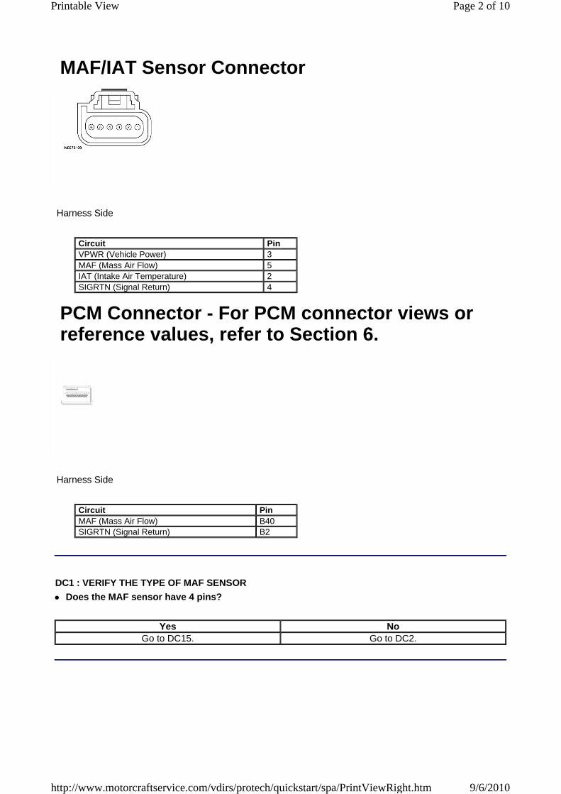
MAF/IAT Sensor Connector
Harness Side
Circuit PinVPWR (Vehicle Power) 3MAF (Mass Air Flow) 5IAT (Intake Air Temperature) 2SIGRTN (Signal Return) 4
PCM Connector - For PCM connector views or reference values, refer to Section 6.
Harness Side
Circuit PinMAF (Mass Air Flow) B40SIGRTN (Signal Return) B2
DC1 : VERIFY THE TYPE OF MAF SENSOR
Does the MAF sensor have 4 pins?
Yes NoGo to DC15. Go to DC2.
Page 2 of 10Printable View
9/6/2010http://www.motorcraftservice.com/vdirs/protech/quickstart/spa/PrintViewRight.htm
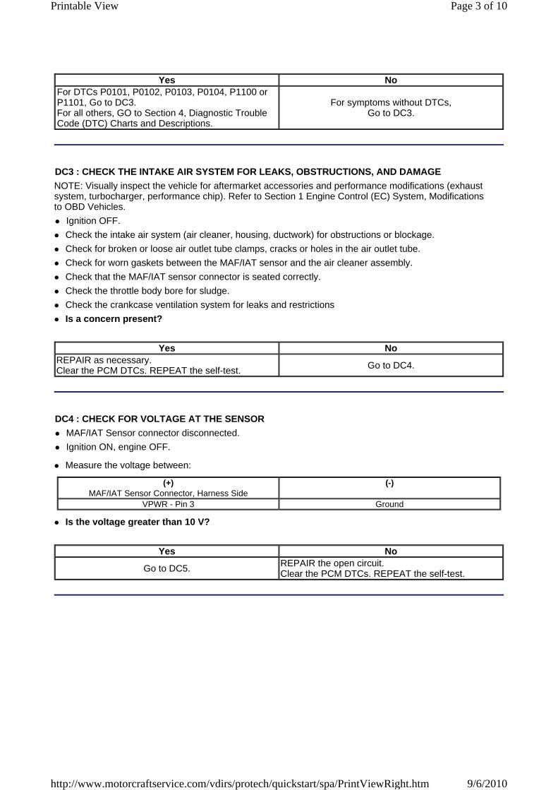
Yes NoFor DTCs P0101, P0102, P0103, P0104, P1100 or P1101, Go to DC3. For all others, GO to Section 4, Diagnostic Trouble Code (DTC) Charts and Descriptions.
For symptoms without DTCs, Go to DC3.
DC3 : CHECK THE INTAKE AIR SYSTEM FOR LEAKS, OBSTRUCTIONS, AND DAMAGE
NOTE: Visually inspect the vehicle for aftermarket accessories and performance modifications (exhaust system, turbocharger, performance chip). Refer to Section 1 Engine Control (EC) System, Modifications to OBD Vehicles.
Ignition OFF.
Check the intake air system (air cleaner, housing, ductwork) for obstructions or blockage.
Check for broken or loose air outlet tube clamps, cracks or holes in the air outlet tube.
Check for worn gaskets between the MAF/IAT sensor and the air cleaner assembly.
Check that the MAF/IAT sensor connector is seated correctly.
Check the throttle body bore for sludge.
Check the crankcase ventilation system for leaks and restrictions
Is a concern present?
Yes NoREPAIR as necessary. Clear the PCM DTCs. REPEAT the self-test. Go to DC4.
DC4 : CHECK FOR VOLTAGE AT THE SENSOR
MAF/IAT Sensor connector disconnected.
Ignition ON, engine OFF.
Measure the voltage between:
(+) MAF/IAT Sensor Connector, Harness Side
(-)
VPWR - Pin 3 Ground
Is the voltage greater than 10 V?
Yes No
Go to DC5. REPAIR the open circuit. Clear the PCM DTCs. REPEAT the self-test.
Page 3 of 10Printable View
9/6/2010http://www.motorcraftservice.com/vdirs/protech/quickstart/spa/PrintViewRight.htm
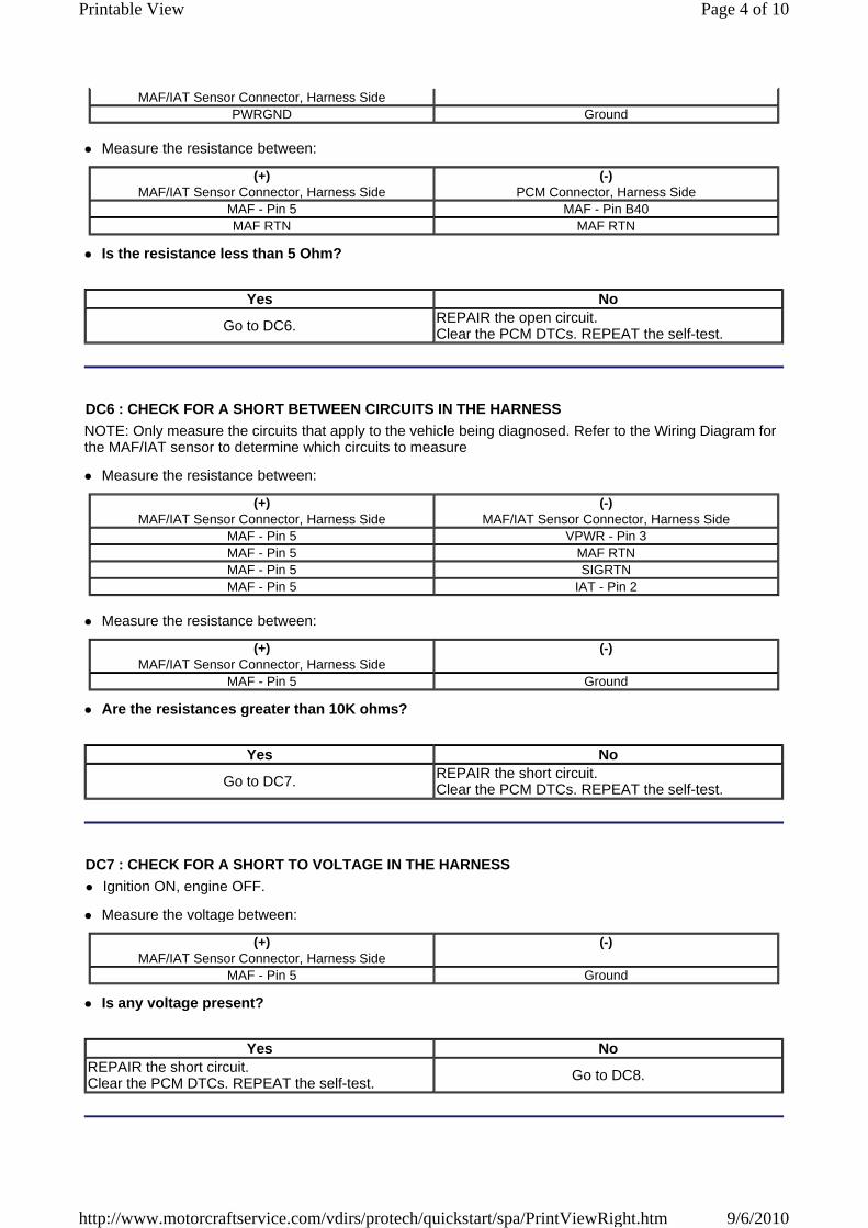
MAF/IAT Sensor Connector, Harness SidePWRGND Ground
Measure the resistance between:
(+) MAF/IAT Sensor Connector, Harness Side
(-)PCM Connector, Harness Side
MAF - Pin 5 MAF - Pin B40MAF RTN MAF RTN
Is the resistance less than 5 Ohm?
Yes No
Go to DC6. REPAIR the open circuit. Clear the PCM DTCs. REPEAT the self-test.
DC6 : CHECK FOR A SHORT BETWEEN CIRCUITS IN THE HARNESS
NOTE: Only measure the circuits that apply to the vehicle being diagnosed. Refer to the Wiring Diagram for the MAF/IAT sensor to determine which circuits to measure
Measure the resistance between:
(+) MAF/IAT Sensor Connector, Harness Side
(-)MAF/IAT Sensor Connector, Harness Side
MAF - Pin 5 VPWR - Pin 3MAF - Pin 5 MAF RTNMAF - Pin 5 SIGRTNMAF - Pin 5 IAT - Pin 2
Measure the resistance between:
(+) MAF/IAT Sensor Connector, Harness Side
(-)
MAF - Pin 5 Ground
Are the resistances greater than 10K ohms?
Yes No
Go to DC7. REPAIR the short circuit. Clear the PCM DTCs. REPEAT the self-test.
DC7 : CHECK FOR A SHORT TO VOLTAGE IN THE HARNESS
Ignition ON, engine OFF.
Measure the voltage between:
(+) MAF/IAT Sensor Connector, Harness Side
(-)
MAF - Pin 5 Ground
Is any voltage present?
Yes NoREPAIR the short circuit. Clear the PCM DTCs. REPEAT the self-test. Go to DC8.
Page 4 of 10Printable View
9/6/2010http://www.motorcraftservice.com/vdirs/protech/quickstart/spa/PrintViewRight.htm
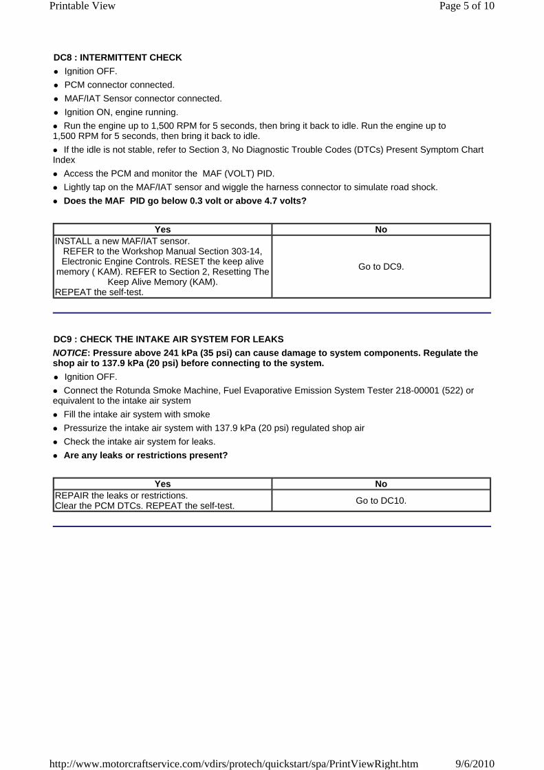
DC8 : INTERMITTENT CHECK
Ignition OFF.
PCM connector connected.
MAF/IAT Sensor connector connected.
Ignition ON, engine running.
Run the engine up to 1,500 RPM for 5 seconds, then bring it back to idle. Run the engine up to 1,500 RPM for 5 seconds, then bring it back to idle.
If the idle is not stable, refer to Section 3, No Diagnostic Trouble Codes (DTCs) Present Symptom Chart Index
Access the PCM and monitor the MAF (VOLT) PID.
Lightly tap on the MAF/IAT sensor and wiggle the harness connector to simulate road shock.
Does the MAF PID go below 0.3 volt or above 4.7 volts?
Yes NoINSTALL a new MAF/IAT sensor.
REFER to the Workshop Manual Section 303-14, Electronic Engine Controls. RESET the keep alive
memory ( KAM). REFER to Section 2, Resetting The Keep Alive Memory (KAM).
REPEAT the self-test.
Go to DC9.
DC9 : CHECK THE INTAKE AIR SYSTEM FOR LEAKS
NOTICE: Pressure above 241 kPa (35 psi) can cause damage to system components. Regulate the shop air to 137.9 kPa (20 psi) before connecting to the system.
Ignition OFF.
Connect the Rotunda Smoke Machine, Fuel Evaporative Emission System Tester 218-00001 (522) or equivalent to the intake air system
Fill the intake air system with smoke
Pressurize the intake air system with 137.9 kPa (20 psi) regulated shop air
Check the intake air system for leaks.
Are any leaks or restrictions present?
Yes NoREPAIR the leaks or restrictions. Clear the PCM DTCs. REPEAT the self-test. Go to DC10.
Page 5 of 10Printable View
9/6/2010http://www.motorcraftservice.com/vdirs/protech/quickstart/spa/PrintViewRight.htm
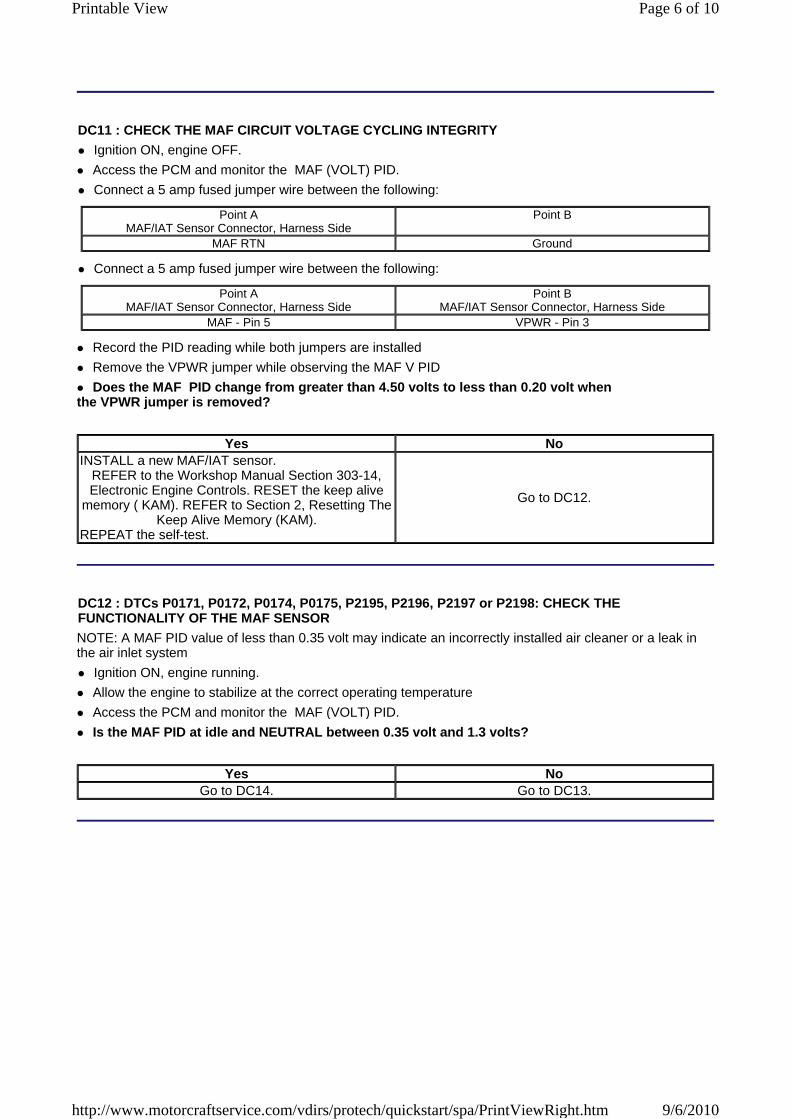
DC11 : CHECK THE MAF CIRCUIT VOLTAGE CYCLING INTEGRITY
Ignition ON, engine OFF.
Access the PCM and monitor the MAF (VOLT) PID.
Connect a 5 amp fused jumper wire between the following:
Point A MAF/IAT Sensor Connector, Harness Side
Point B
MAF RTN Ground
Connect a 5 amp fused jumper wire between the following:
Point A MAF/IAT Sensor Connector, Harness Side
Point B MAF/IAT Sensor Connector, Harness Side
MAF - Pin 5 VPWR - Pin 3
Record the PID reading while both jumpers are installed
Remove the VPWR jumper while observing the MAF V PID
Does the MAF PID change from greater than 4.50 volts to less than 0.20 volt when the VPWR jumper is removed?
Yes NoINSTALL a new MAF/IAT sensor.
REFER to the Workshop Manual Section 303-14, Electronic Engine Controls. RESET the keep alive
memory ( KAM). REFER to Section 2, Resetting The Keep Alive Memory (KAM).
REPEAT the self-test.
Go to DC12.
DC12 : DTCs P0171, P0172, P0174, P0175, P2195, P2196, P2197 or P2198: CHECK THE FUNCTIONALITY OF THE MAF SENSOR
NOTE: A MAF PID value of less than 0.35 volt may indicate an incorrectly installed air cleaner or a leak in the air inlet system
Ignition ON, engine running.
Allow the engine to stabilize at the correct operating temperature
Access the PCM and monitor the MAF (VOLT) PID.
Is the MAF PID at idle and NEUTRAL between 0.35 volt and 1.3 volts?
Yes NoGo to DC14. Go to DC13.
Page 6 of 10Printable View
9/6/2010http://www.motorcraftservice.com/vdirs/protech/quickstart/spa/PrintViewRight.htm
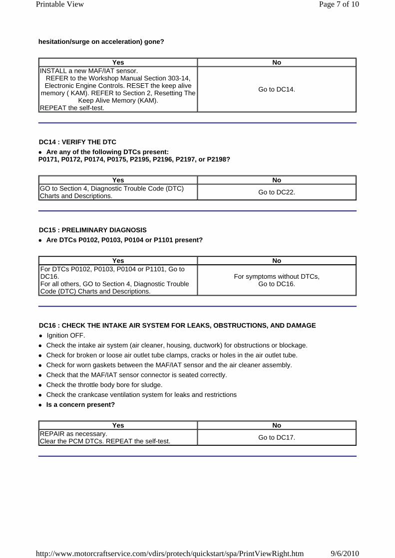
hesitation/surge on acceleration) gone?
Yes NoINSTALL a new MAF/IAT sensor.
REFER to the Workshop Manual Section 303-14, Electronic Engine Controls. RESET the keep alive
memory ( KAM). REFER to Section 2, Resetting The Keep Alive Memory (KAM).
REPEAT the self-test.
Go to DC14.
DC14 : VERIFY THE DTC
Are any of the following DTCs present:P0171, P0172, P0174, P0175, P2195, P2196, P2197, or P2198?
Yes NoGO to Section 4, Diagnostic Trouble Code (DTC) Charts and Descriptions. Go to DC22.
DC15 : PRELIMINARY DIAGNOSIS
Are DTCs P0102, P0103, P0104 or P1101 present?
Yes NoFor DTCs P0102, P0103, P0104 or P1101, Go to DC16. For all others, GO to Section 4, Diagnostic Trouble Code (DTC) Charts and Descriptions.
For symptoms without DTCs, Go to DC16.
DC16 : CHECK THE INTAKE AIR SYSTEM FOR LEAKS, OBSTRUCTIONS, AND DAMAGE
Ignition OFF.
Check the intake air system (air cleaner, housing, ductwork) for obstructions or blockage.
Check for broken or loose air outlet tube clamps, cracks or holes in the air outlet tube.
Check for worn gaskets between the MAF/IAT sensor and the air cleaner assembly.
Check that the MAF/IAT sensor connector is seated correctly.
Check the throttle body bore for sludge.
Check the crankcase ventilation system for leaks and restrictions
Is a concern present?
Yes NoREPAIR as necessary. Clear the PCM DTCs. REPEAT the self-test. Go to DC17.
Page 7 of 10Printable View
9/6/2010http://www.motorcraftservice.com/vdirs/protech/quickstart/spa/PrintViewRight.htm
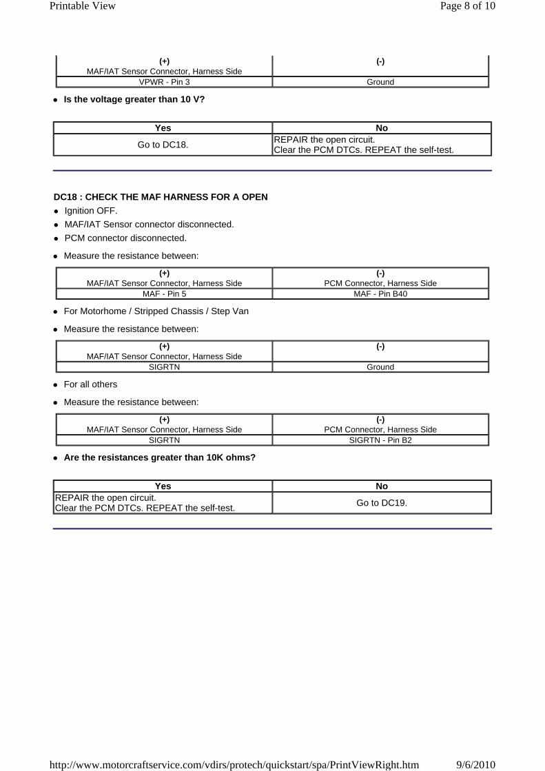
(+) MAF/IAT Sensor Connector, Harness Side
(-)
VPWR - Pin 3 Ground
Is the voltage greater than 10 V?
Yes No
Go to DC18. REPAIR the open circuit. Clear the PCM DTCs. REPEAT the self-test.
DC18 : CHECK THE MAF HARNESS FOR A OPEN
Ignition OFF.
MAF/IAT Sensor connector disconnected.
PCM connector disconnected.
Measure the resistance between:
(+) MAF/IAT Sensor Connector, Harness Side
(-)PCM Connector, Harness Side
MAF - Pin 5 MAF - Pin B40
For Motorhome / Stripped Chassis / Step Van
Measure the resistance between:
(+) MAF/IAT Sensor Connector, Harness Side
(-)
SIGRTN Ground
For all others
Measure the resistance between:
(+) MAF/IAT Sensor Connector, Harness Side
(-)PCM Connector, Harness Side
SIGRTN SIGRTN - Pin B2
Are the resistances greater than 10K ohms?
Yes NoREPAIR the open circuit. Clear the PCM DTCs. REPEAT the self-test. Go to DC19.
Page 8 of 10Printable View
9/6/2010http://www.motorcraftservice.com/vdirs/protech/quickstart/spa/PrintViewRight.htm
Yes No
Go to DC20. REPAIR the short circuit. Clear the PCM DTCs. REPEAT the self-test.
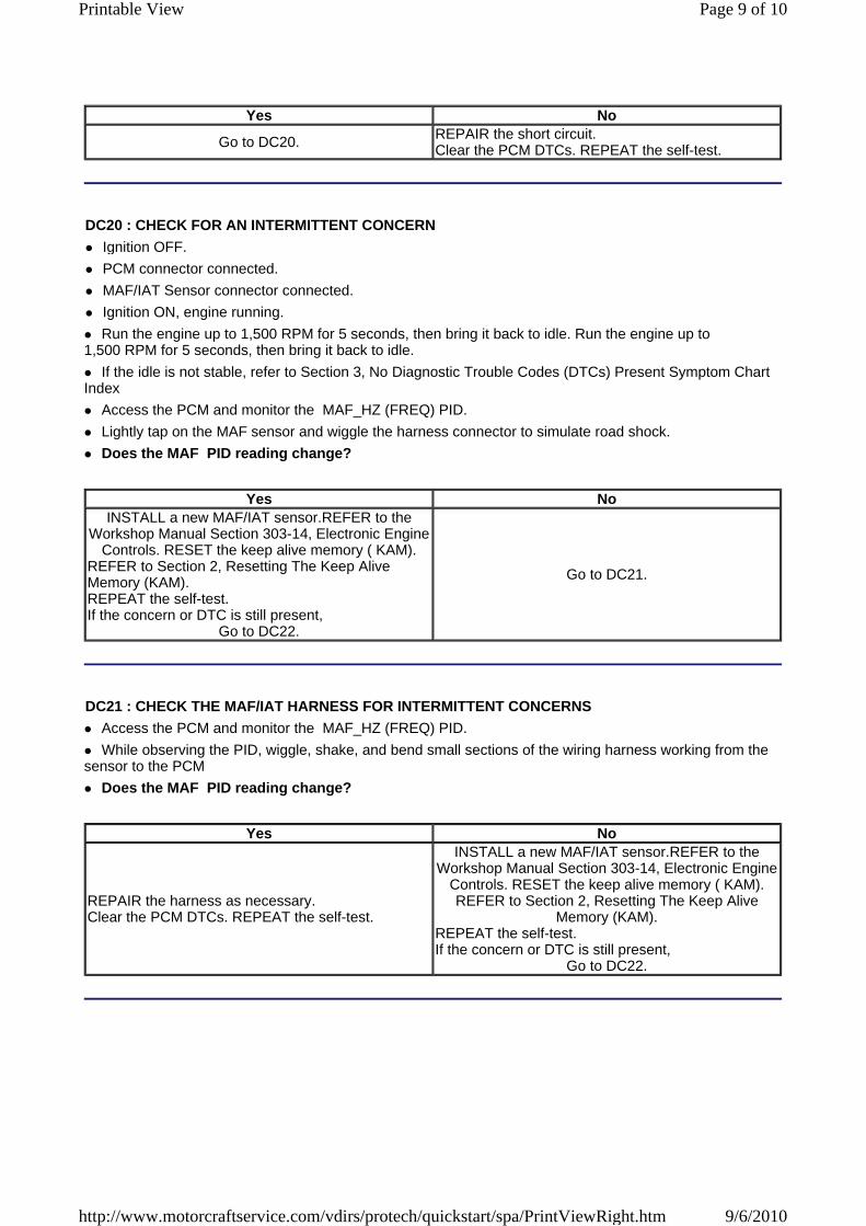
DC20 : CHECK FOR AN INTERMITTENT CONCERN
Ignition OFF.
PCM connector connected.
MAF/IAT Sensor connector connected.
Ignition ON, engine running.
Run the engine up to 1,500 RPM for 5 seconds, then bring it back to idle. Run the engine up to 1,500 RPM for 5 seconds, then bring it back to idle.
If the idle is not stable, refer to Section 3, No Diagnostic Trouble Codes (DTCs) Present Symptom Chart Index
Access the PCM and monitor the MAF_HZ (FREQ) PID.
Lightly tap on the MAF sensor and wiggle the harness connector to simulate road shock.
Does the MAF PID reading change?
Yes NoINSTALL a new MAF/IAT sensor.REFER to the
Workshop Manual Section 303-14, Electronic Engine Controls. RESET the keep alive memory ( KAM).
REFER to Section 2, Resetting The Keep Alive Memory (KAM). REPEAT the self-test. If the concern or DTC is still present,
Go to DC22.
Go to DC21.
DC21 : CHECK THE MAF/IAT HARNESS FOR INTERMITTENT CONCERNS
Access the PCM and monitor the MAF_HZ (FREQ) PID.
While observing the PID, wiggle, shake, and bend small sections of the wiring harness working from the sensor to the PCM
Does the MAF PID reading change?
Yes No
REPAIR the harness as necessary. Clear the PCM DTCs. REPEAT the self-test.
INSTALL a new MAF/IAT sensor.REFER to the Workshop Manual Section 303-14, Electronic Engine
Controls. RESET the keep alive memory ( KAM). REFER to Section 2, Resetting The Keep Alive
Memory (KAM). REPEAT the self-test. If the concern or DTC is still present,
Go to DC22.
Page 9 of 10Printable View
9/6/2010http://www.motorcraftservice.com/vdirs/protech/quickstart/spa/PrintViewRight.htm
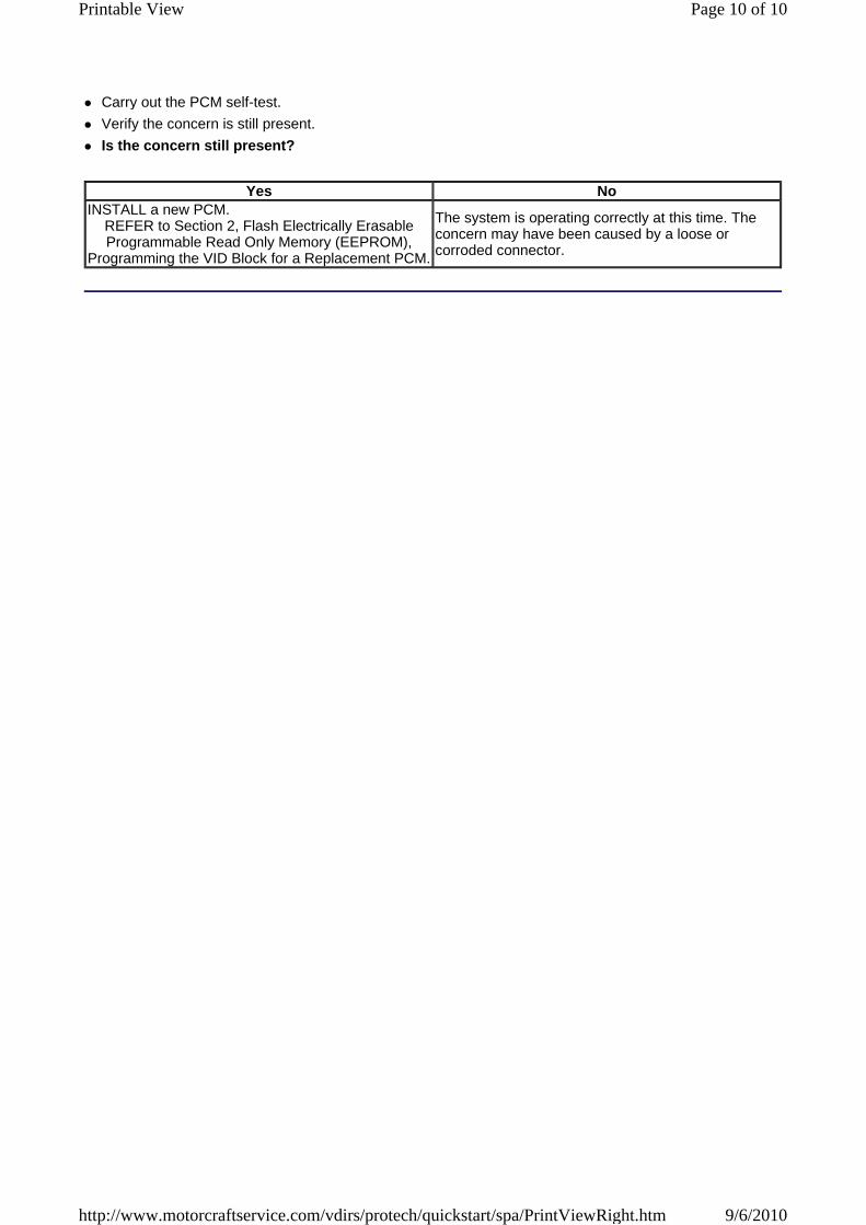
Carry out the PCM self-test.
Verify the concern is still present.
Is the concern still present?
Yes NoINSTALL a new PCM.
REFER to Section 2, Flash Electrically Erasable Programmable Read Only Memory (EEPROM),
Programming the VID Block for a Replacement PCM.
The system is operating correctly at this time. The concern may have been caused by a loose or corroded connector.
Page 10 of 10Printable View
9/6/2010http://www.motorcraftservice.com/vdirs/protech/quickstart/spa/PrintViewRight.htm