masonry prefabrication - universidade do minho · masonry prefabrication ... in beton-oder...
TRANSCRIPT

1 . b . 2
MASONRY PREFABRICATION
WALTER Lo DICKEY
civi~ & Struatura~ Engineer Los Ange~es , Ca~ifomia 90042, V. S.A.
MASONRY PREFA"BRICATION
This desaribes severa~ prefabriaated bui~dings and
different systems used, espeaia~~y aonsidering high
wind or seismia resistanae. It points out the diff
erent types of fabriaation and aonneations for ~oad
bearing e~ements as aontrasted to non-struatura~ aur
tain wa~~ aonstruation .
It a~so compares different types o f fabrication, i.e .,
on-site, off-site, manua~ vs machine prefabriaated
pane~s. A~so, some unusua~ and effective shapes poss
ib~e . Detai~s are shown that provide adequate strength
for deve~opment of high capacity as opposed to detai~s
that provide " pane~ support whi~e permitting ~arge
storey drift for conarete or stee~ frame construation.
MACONNERIE PREFABRIQUEE
Cet artide ana~yse divers systemes de bâtiments pré
fabriqués , p~us spécia~ement aeux qui présentent une
résistance partiau~iere aux vents tres puissants et
aux seaousses te~~uriques . L 'attenti on est attirée
SUl' ~es différentes manieres de ws réaUser et SUl'
wS raaaords entre-eux des é~éments portants, en com
paraison avec une aonstruction errpZoyant des murs
rideaux non portants .
Diverses méthodes de préfabriaation sont aomparées
ici , par exerrp~e ae~Zes empZoyées SUl' ahantier ou en
usine et aeZZes qui sont manuel~es par rapport à ae~
~es qui purent être mécanisées . D'autre part ~ 'on
examine aussi des fOI'fl/es réa~isabws bien que non
usue~~es . L 'ana~yse est p~us détai~~ée en ce qui aon
aeme ~a résistanae souhaitée pour ~ 'éZaboration de
panneaux à grande résistanae et Zes problemes en rap
port avec ~ 'étançonnement des panneaux areux à rerrp Ur,
uti~isés sur sque~ette d'acier ou de béton .
VORFERTIGVNG DES MAUERWERKS
Diesel' Beitrag besahreibt einige vorgefertigte Ge
lxfude und die Systeme, die angeu:zndt wurden, wo
bei besonders eingegangen wird auf den Widerstand
gegen H6henwinde und Erdbeben.
Es werden verschiedene M6g~ichkeiten aufgezeigt
far die Herste~~ung und Verbind~~ von tragenden
E~ementen im Gegensatz zu niaht-tragenden Vorhang
fassaden .
Verschiedene M9t.l!oden der Vor f ertigung werden ver
g~iahen, auf der Baustel~e und in der Fabrik,
manue~~ und maschine~~. Auch einige ungewohn~iche ,
jedoch móg~iche FOI'fl/en .
Genauer eingegangen wird auf die angemessene
Starke für die Entwick~ung der der ~ndtafeln mit
hohem Widerstand und auf die Probleme, die siah
ergeben bei dem Unterstützen von Ausfachungstafeln
in Beton- oder StahZskeZetten.
GEPREFABRICEERD METSELWERK
Deze mededeZing besahrijft verschi~Zende geprefabri
ceerde gebouwen en de systemen die er voor gebruikt
werden, speaiaal in verband met de weerstand tegen
sterke windkraahten, windbe~astingen en aardbevingen.
Aandaaht wordt besteed aan de verschiZZende manieren
van fabrikatie , aan de verbindingen van dragende e~e
menten en aan de kontrasten met niet-dragende v~ies
gevels.
VerschiZ ~ende methoden van prefabrikatie worden ver
geZeken, bijvoorbeeZd op de werf en i n de fabriek
aZsmede manueel en machinaa~ . Verder sommige onge
wone, doah mpgeZijke VOI'fl/en . Meer in detai~ wordt
ingegaan op de gepaste sterkte voor de ontwikke~ing
van panelen met hoge weerstand en de problemen in
verband met ondersteuning van invuZpane Zen in beton
of staaZskelet.


INTROOUCTION
Pre-fab is fabulous in many ways because of the many advantages and its us e has been developing alI over the world , with growth of many systems and methods depending upon local condi t ions .
This paper wil l emphasize the r eq uiremen ts for use of p re fabricated panels in seismic areas in addition to win d l oads . In thes e areas, the buil dings are subjected to lateral f orces and tendency for moti on in addition to the simple l oads such as might be imposed by wind loads .
On e advantage to the deve l opment of masonry prefabri cation has been the preceding highly developed prefab rication of precast con crete elements . Eq uipment has been developed to accomplish the delivery and in stallation of precast elements, and i t is available for delivery and installation of prefabricated brick pane ls . In addition, the design pr ofession, that is , t he architects and enginee r s as we l l as the contractors , have become more skilled in th e use of prefabri cated e l ements . Also , emotionally , it is re cognised that many professionals r ecognise that pr efabrication is one of the newest techniques and should probably be used for better servi ce to the client.
TYPES
Gene ral
Since prefabrication has been developing in many different areas with many different local conditions the re are ve ry many different de tail typ es . However, these might be divided into certa in groups as follows :
(1) man ually fabricated at a plant , transport ed and erected
(2) manua lly fabricated at a site, moved and e rected
(3) mach i ne f abricated at a plant , transported and e rected
Examp l es of each of these that have developed in areas subject to seismic activity and under seis mic design cons iderations, will be given . This listing will not be a total coverage of the ty pes , but merely a few representati ve t ypes to illustrate certain point s .
Fibriwall
This is Fabricated Brick Reinfo rced Walls . Before going into this business of prefabri cation , ext ensive studi es were made in Europe and throughout the Un it ed States . As a r esu lt of these studi es and wi th a con si derable resea rch program , that system of fabri cated br ick reinforced wall systems was developed . I n this system , the panels are assembled horizontally in a factory, using a special fast-setting mortar . These pane ls have been us e d extensive ly in resi den tial construction and serve ve ry effectively in r esidences that will be subject to earthquake l oads because th ey are reinforced and when they are pr operly attach ed , the resulting structure is a much s tronger one than othe r weaker materiaIs such as wood a r plaster .
In many of these installations, no att emp t was made to put windows and doors in the 4 ' wide panels . A l oad bearing wooden panel was prefabricat ed to in clude the windows and doors and these wooden panels are spaced as desired be tween the brick panels .
Each panel 1s lowered into place on the footi ng ar f oundation and aligned with temporary braces a r strut s . Cl i p angles are installed a r dowels are grouted for
1 . b . 2-1
connect i on . At the top , a wooden plate similar to a wcode n plat e on a wooden house is attached and p r ovides roof s uppo r t at the top of the panels simil ar to the function in wood panel houses .
Masonry Sys.tems
This is one of t he ea rly fab ri cat in g systems of brickwo rk. It consists of fa cto ry fabricated pane ls laid us ing a high bond mo rtar. Many p lants throughout t he United Sta tes i nc luding the West , have utilised t his basic system . One con tai ns a se ri es of long platforms on which the desired pane l s are hand laid . I n this sys t em , however, the scaffold is movab l e by moto r, the material is fed prope rly , and the bri cks are fur nished to the scaffold convenie nt ly so that the production of the hand -laid work can be ve ry great with resulting speed of construction and much lower costs due to de c r eased labor cost.
Modu lar Precast Panels
This cons ists of a panel syst em in which bricks are placed on segmented mats and groute d . These are then transported t o the field and erected . with the proper connections .
San Oiego . Ca lifornia
This consisted of a series of concrete b lock pane l s manufactured by hand-lay ing at a concret e block plant o then tran spo rting and erecting in place . The panels were built with ordina ry mo r tar with some ve rtical grouted cells in which lifting loops with r einfo r cing ba rs were grouted . Th e r emainder of the ce ll s we r e not grouted . until the panels were lifted into place ove r dowels that pr ojected f r om the foundation . Ve rti ca l r ein f orcing was added to lap thos e dowels and the cells gro uted ·to provide a reinforce d wall .
Seattle. Wash i ngton
One con tractor in Seattle has fo ll owed a similar method of handlaying masonry for delive ry and e recti on of pre fabricated pa ne l s . His pl ant is simple but very effecti ve . It consists of a housing she lter ar gantry mou nt ed on four wheels on a long track . Tbe men wo rk under t his prot ect ing shelter . Also there are guides mounted on the movab l e gantry frame on wh ich guidelines can be mounted f or plumb laying of the wall shapes with accurate coursing . The scaffold is motorised so that with a touch of the foot the scaffold can be raised a course . Hence the b r ick lay e r s are contin ually laying at the mos t effici en t W9ist height a nd can be most product i ve . very easi ly . One economic advantage to th is system i s that ~ he re can be a sma ll highly skilled crew working s teadily without fluctuations or hi r ing ar firing of new personnel. In this way, the wo rk done by a highly t rai ned and pr oductive c r ew . under efficient working conditions will be mo r e economi cal .
One ve r y effective pr oject r ecent ly accomplished by him was a seven-story building in Po rt land . Oregon . The pe neIs we r e fabricated in the Seattle plant o transpo rted and erected . Thes e panels used the 4" ho ll ow r einfo rceabl e brick . By partially reinforcing the panels before delive ry , they can be delivered without distress using o rdinary conventional mo rtar and gr out . These a re ho llow brick manufactu r ed unde r t he standards developed by the Weste r n States Clay Products Assoc iation , f or Hollow Reinforced cell bric k . This particular proj ect consisted of angular sloping enc l osures t o t he struc t ura l stee l frame to provide the outer facin g of the building and the fireproofi ng of the st r uc tural steel frame . It demonstrated exceIlent speed of const ru ct i on as well as economy . ActuaIIy , in bid compe tition, the reinfo rced brick panels were cheaper than precast concre t e fo r the same shape . One interesting aspect of th e spandrel coverings was that t hey were s ol dier courses . i . e . , with the bed courses
1 . b . 2-2
vertical . These were produced by l aying horizontal bed joints and then rotating the panels 90° during i nstallation .
Tomax
This is a method in which masonry panels are fabricated at a plant and then delivered and erected in the field. Initially this has been designed for 8 " concrete block walls, a l though it can be used for 4", 6", 8" and 12". Also, the ~ewer , ho ll ow reinforceable bricks, which are very similar in shape to the concrete block shape, can be used very effective ly. Th ere are several of these plants in the Western area fabricating , e r ecting and connecting their panels for the earthquake requirements of the UBe codes of the West .
The basic operation of the machine is as follows . The units are placed on the conveyor in a pre-deter mined manner depending on the bond desired and the type of unit needed for each individual course . The machine automatically spaces the blocks to an accurate modular horizontal dimensiono Forms, like fingers, close the side of the head j oi nt and mortar is vibrated into place. The blocks then feed forward one unit and a bed joint is placed on top o This operation is repeated block by block for the course , the b locks move forward on a meta l track that keeps them in alignment.
After the correct number of b l ocks pass through the machine for a course, the huge clamp, operated by air, aut omatica lly picks up the co urse and places it to the side on top of the previous course. It is then vibrated into place to an exact height . The alignment of the wall on one side is perfect . If the blocks are not precisio n in width, the variation will show only on one side of the wall . Fo r example, if split blocks are used, the one face would be true, but the othe r face will show the irregularities. The irregularities are accommodated by a hydraulic variable face on the one side of the clamp .
The resulting panel is a preclslon panel , accurate and true on one edge and the dimensions are precise overall . Some of the machines 'are designed to build panels as long as 30 ', but most of the machines provi de a panel 24 ' long because that is the maximum length for an 8" thick wall, according to the UBe limits. They also normally build a pane l about 12 ' high so they can be trucked on the highways.
After the panel has been completed, the pallet on which it was erected moves a certain distance and a new pallet is placed on which the next panel is fabri cated . The long pallets are moved by a continuous chain and the panels move laterally without being disturbed while the mortar is still fresh . They are placed in the curing or storing yard by fork lifts. This handling is permitted be cause of the extremely high strength mortar joints that have begn vibrated in place by the machine . No high bond mortar or chemical additives are necessary, merely a properly proportioned coment and sand mortar .
If joint reinforcing or horizontal steel is required in the panels, it is very easily placed, by hand, on the wall on t he proper courSe without slowing down the machi ne. Vertical steel can be placed after the panel is fi nished and the panel rolled away from the ·machine, but very frequently the vertical stee l is not placed until the panel is in position on the job. Then the steel is placed, and grout is poured into the cells bonding the steel, providing a completed structure . Th e grouting in place with the dowels provides continuity of reinforcement as desired or as necessary for the structure.
This scheme was designed to be utilized in competition with the precast, so-ca ~l ed tilt-up, panel which has
made great inroads economical ly in the warehouse and commercial building construction field.
One very interesting hollow unit prefab project was a mini warehouse . It is a complex in which many people could rent small warehouse spaces for storage . Prefab masonry was much faster and much cheaper than either precast concrete or hand-laid masonry in-place.
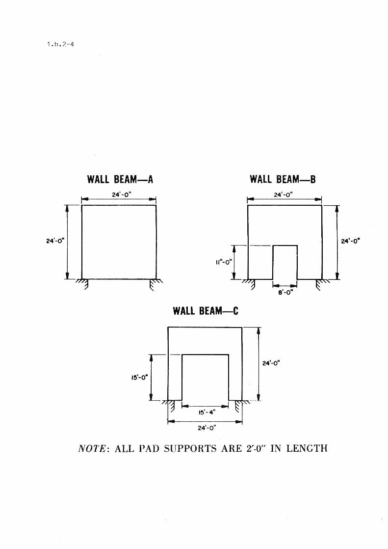
WALL BEAM
This is a scheme of utilizing wa l ls serving as beams to span between caissons or pad footings. This principle provides that walls 'may span farther without the usual bearing wall limits and stress reduction .
A test program conducted by Masonry Institute of America with brick manufacturers and block manufacturers was to determine the validity of this principle, since it had been developed and used for a long time with tilt-up , or precast, concrete panels . The use is versatile . The pane l s can be bui l t in place or on sepa rate pads a nd moved into position. Also, the principle has been used with the machine fabricated wa ll s which were delivered in sections, for example , a 24' high wall was delivered in two 12' heights. These were connected by grouting .
The test facilities consisted of a series of foundation pads on which panels could be erected , and a set of three be lled . caissons. Two were the end supports for the panels, and one was a hold down with heavy rods projecting. A steel plate was provided on each end caisson to support the panels . eonnections were made for rods that extended to the top for transferring the jack load. A distributing beam was made to receive the jack loa d and transfer it to the panel as a partially distributed concentrated load at the top o
The panels tested consisted of:
(11 9" brick wall consisting of 3" brick , 3 " grout and 3 " brick, 24 ' by 24 ', reinforcing was the standard reinforcing used for masonry const ruction and was instr umented in order to determine stress distribution.
(21 8" hollow brick wall, 24 ' by 24' , with conventional masonry reinforcement. Its actual thickness was 71 ", giving it an actual h/t of 38 as compared to the maximum permitted for bea ring walls of 25.
(31 8" co ncrete b l ock panel, 24' by 24 ', with the conventional normal re i nforcing of block walls.
(41 6" concrete block panel, 18' by 24 ', actual thickness an h/t of 52 compared to the maximum of 25 Permitted for bearing walls.
The pri nciple had been proven many years before . The author was chairman of a precast concrete committee which included this deep beam principle with limits far beyond those of normal bearing walls . The Portland eement Association had provided a brochure of sophisticated deep girder design, presenting curVes so that it could be used easi ly. However the capacities of these tested panels were so far beyond the loads that might be applied, that a very simple approxi mate equation was used for these panels in their I eBO Research Recommendation approval .
Th e test demonstrated the extremely high facto r of safety of this principle. The anticipated design load on these panels in their intended use would be 16 kips. Th e failures in alI cases were due to local bearing under the load application of the jack near their maximum load capacity, that is 175 kips, or at a factor of safety greater than ten . In no case was

there a pa"el type failure.
In order to dete r mine the ultimate load the panels might carry, the 6" panel was retested with 2 jacks. A concrete distributing beam was poured on the top portion where there had been local crushing under the jack . In this case, the load was applied eccentrically and developed 246 kips before it failed . The failu r e was by crushing at one of the stee l plate supports at an over l oad of fifteen times, 246 kips. It failed due to local crushing, th ere f ore , it is obvious that there is a great factor of safety in the function of these wall panels as wall beams .
Openings
The panels had been tested with no openings , therefore , one could use solid pa nels in a build i ng . This would have a practical problem ; there would be three alternati ve possibilities fo r getting into and out of the bui l ding . One method suggested was (A) to provide a ladder up the side and to the r oof , another method (ô) was to dig a tunne l unde r the solid wall , and anot her alterna ti ve (C) which , of course . was more feasible , was to pr ovide openings in the panel . The feasibility and possibility of providing these open ings was checked by a finite e l emen t computer programo
The computer program determined th e stresses at various criticaI points on t he p anel for a solid panel , a panel with an 8 ' opening , and a panel with a 15' opening . This indicat ed that the 8 ' opening did not introduce appreciable stresses , but that the 15 ' panel out of the 24 ' wall introduced considerable stresses and would be about the maximum that could be used in such a pane l. If larger openings were r eq uired, it would be better to provide columns as jambs and support a panel over the opening to function as a wall beam lintel .
CONNE CTI ONS
Gene r a l
There are two basically different types of function that the panel connections must perform . One is f o r the wall f unctioning as a curtain wall support ed by a structure which , reI ative to the pane L is rath er flexi b le. In this case , the bui l ding must be permitted to deflect with allowab le story drift without imposing that deformation on the panel, but still preventing its falling inward or outwar d . The second type of connection is for a panel connected rigidly to the structu r e and providing the latera l support as well as the vertical support in the structure , In this case , the connections must be strong enough to carry the load, not merely permit deflection .
Curtain Wall Connections
These must support the panel in place to r esis t vlinds inward and outward and also must permit the mo re flexible structural frame to move . The deflection of the structure perpendi cu lar to the plane of the panel me r ely imposes some slight end r otatinn . R8sily accommodated. Howeve r , these panels are very stiff inplane and the connection must perm'i t a rela ti ve sl , ry drift without st res sing the pa nel . Some typic a l c : ~
nection s for this function are c l ip angles with slotted ho l es o r straps o r ba r s extending back to s upports . The flexibility of the strap or bar will permit the desi r ed relative motion in t he p lane of the wa ll . ,This last is the most desirable because i t is more ce rtai n . The slot t ed holes in cl i p ang les very frequently wil l bind and no t function when desired.
Structural Connections
These connections which must carry the s tructural load to the stiff panel must be strong . One good me thod is
1 . b . 2-3
. to leave cells open in which dowels and re~nforcing bars are placed and grouted . This makes ve ry strong connections and incorpo r ates the panels into the building structural system integrally .
MARKET
One of the reasons for developing masonry prefabrication was to compete economically with precast concret e and other systems . One big area was the large warehouse type of construction in which tilt - up dominated . AIso , the panels were t o compete economically and functionally with the wood house construction which completely dominated t hat rrarket . In certain instances panels can be prefabricated wh ich could not be done feasibly by field in - place hand placed masonry . This was true in the building in Po rtland. Anot he r great advantage is the speed of construction . This introduces savings in interest on loaned money and earlier income because of the quicker occupancy .
In add ition it is found that with the new equipment availabl e the prefabricated elemen ts can not only be faster , bu t may be lower cost in many instances . Therefore, it seems obv ious the market for prefabricated panels is going to grow tremendo usly in the next few years . Now it has a very good f oundation upon which to base that growth .
1. b . 2 -4
WALL BEAM-A WALL BEAM-B 24'-0" 24'-0"
,-
24'-0" 24'-0·
nJ ~ ~ ~ ",,",", , .. 8 -O
WALL BEAM-C
r--
24'-0"
-7, ~~ ~ ~~ ;"
15'-4"
24'-0"
NOTE: ALL PAD SUPPORTS ARE 2'-0" IN LENGTH

International Conference of Building Officials
IIESEllle. eDmnllnEE IIEeDmmEnDITlDn
MASONRY DEEP WALL BEAMS ( REINFORCED BruCK WALL PANELS ) MASONRY lNSTlTUTE OF AMERICA 2550 BEVERLY BOULEVARD LOS ANCELES, CALlFORNIA 90057
80ISE-CASCADE CORPORATION I NDUSTRIAL DEV. DlV " ENCINEERS ANO CQSTRACTORS 16901 SOUTIf WESTERN AVENUE CARDENA , CALIFORNIA 90247
I . Inlroduction: At lhe request af Ma sonry Ins titute af Amer ica, Los Angeles, Cali fomia, lhe Resca rch Committec af lhe Inte rna tiooa l Conference of Building Offidals has ma de a re-examinal ion af ,the !esl data submitted in connection with lhe use af lhe Masoo l)' Deep Wall Bearns designed to span ht>twecn isobted footings.
JI . Description : Genera l : The masonry deep wall ocams are designed to span betwecn isoJatcd footing.~ and are construcled a f eithcr reinforccd grouted c1ay brick ar grouled clay bloeks d es igned and reinforced in compliance with lhe requiremenls a f Chapter 24 a f the Uniform Building Code. The deep \ValI beams may he construeted in place ar construcled elsewhere and placed in position by eranc.
Desi gn : The panels are des igned and rons trucled in accord ance with the requirements of Chapte r 24 of lhe Unifonn Bui ld ing Code, excepl as follows:
1. The ratio of heighl lo thickncss shall nol execed 36 for loadbearing or shear walls and no l more Ihan 48 fo r other uses.
Report No. 2727 March , /974
2. The wa lls :\Te supporled upon fOllndation pads loea led aI eaeh ('nel wh ich h:we a le ngth o f he:u ing nol lon§.!:er th an one· leo lh of lhe !'õ p:m .
3. Conct:n l ra ted load· aI reaelion poinls should be considered in lhe design of lhe p:mels hy assuming Ihat a sectioo having a widt h ('qua l lo lhe length of bcarin~ plus !",ie\.· lhe pane l th ickot·ss resisls lhe p:mcl reaelion . Thc allowable compres· sive streng th 0 0 t his scction lt n<ler ",o rkin§.!: strcss design shall I"\f> :
~f~~;~i~h~ll:ir;~I~h:r~I~~lp hbi:';~l t~I~:.~sgl(~; S~~~~~~~~~~~~I:~lb; cons idcred in lhe design o
111. E\'id('nce Submitted: Load tests conducled by Twining La boralories of Sou thern California, Incorporated, are suhmitled .
Recommend ation IV. Recomme nda lion: Tha! lhe masonry deep wall beams are
a satisfacto ry altemale method of cons!ruclion to Ihat speci6ed in lhe niform Building Code pro\'ided dcs ign and cons(ruclion are as set forth in Pari 11 of this reporl.
This recommendalion is subjecl lo annuol re·examination.
The above is an examp l e of special recommendations that are made le60 for s pecia l types of design const ruc tion .
This one provides for good perpendicular methods .
BOTTOM CONNECTION
'-'ELO
NUT
SHIMS
ANCU: OR ?LATF
TO? CONNECTION
The bottom connection provides rigid support vertically and laterally while permit t ing tilt perpendicular t o the panel pla no
The top conne c tion provides s up port perpendicular to the panel plan while pe r mitting in-plane motion . A satisfactory alternative is use of angles wit h sl otted ho l es . Was hers and ferrules will prevent binding .
1 . b . 2 - 5
