masoneilan svi ff - insatechmasoneilan svi ff instruction manual =| 11 use only genuine replacement...
TRANSCRIPT

1
1iii
GE Oil & Gas
Masoneilan* SVI* FF Advanced Performance Digital Positioner Installation and Operation Manual (Rev D)
GE Data Classification: Public

About this Guide
This instruction manual applies to the following instruments and approved software:
SVI FF
with firmware version 1.0.0.1 or higher
with ValVue* version 3.0
with handheld communicator with DD published for SVI FF
The information in this manual is subject to change without prior notice.
The information contained in this manual, in whole or part, shall not be transcribed or copied without GE Oil & Gas’ written permission.
In no case does this manual guarantee the merchantability of the positioner or the software or its adaptability to a specific client needs.
Please report any errors or questions about the information in this manual to your local supplier or visit www.geoilandgas.com/valves.
DISCLAIMER
THESE INSTRUCTIONS PROVIDE THE CUSTOMER/OPERATOR WITH IMPORTANT PROJECT-SPECIFIC REFERENCE INFORMATION IN ADDITION TO THE CUSTOMER/OPERATOR’S NORMAL OPERATION AND MAINTENANCE PROCEDURES. SINCE OPERATION AND MAINTENANCE PHILOSOPHIES VARY, GE (GENERAL ELECTRIC COMPANY AND ITS SUBSIDIARIES AND AFFILIATES) DOES NOT ATTEMPT TO DICTATE SPECIFIC PROCEDURES, BUT TO PROVIDE BASIC LIMITATIONS AND REQUIREMENTS CREATED BY THE TYPE OF EQUIPMENT PROVIDED.
THESE INSTRUCTIONS ASSUME THAT OPERATORS ALREADY HAVE A GENERAL UNDERSTANDING OF THE REQUIREMENTS FOR SAFE OPERATION OF MECHANICAL AND ELECTRICAL EQUIPMENT IN POTENTIALLY HAZARDOUS ENVIRONMENTS. THEREFORE, THESE INSTRUCTIONS SHOULD BE INTERPRETED AND APPLIED IN CONJUNCTION WITH THE SAFETY RULES AND REGULATIONS APPLICABLE AT THE SITE AND THE PARTICULAR REQUIREMENTS FOR OPERATION OF OTHER EQUIPMENT AT THE SITE.
THESE INSTRUCTIONS DO NOT PURPORT TO COVER ALL DETAILS OR VARIATIONS IN EQUIPMENT NOR TO PROVIDE FOR EVERY POSSIBLE CONTINGENCY TO BE MET IN CONNECTION WITH INSTALLATION, OPERATION OR MAINTENANCE. SHOULD FURTHER INFORMATION BE DESIRED OR SHOULD PARTICULAR PROBLEMS ARISE WHICH ARE NOT COVERED SUFFICIENTLY FOR THE CUSTOMER/OPERATOR'S PURPOSES THE MATTER SHOULD BE REFERRED TO GE.
THE RIGHTS, OBLIGATIONS AND LIABILITIES OF GE AND THE CUSTOMER/OPERATOR ARE STRICTLY LIMITED TO THOSE EXPRESSLY PROVIDED IN THE CONTRACT RELATING TO THE SUPPLY OF THE EQUIPMENT. NO ADDITIONAL REPRESENTATIONS OR WARRANTIES BY GE REGARDING THE EQUIPMENT OR ITS USE ARE GIVEN OR IMPLIED BY THE ISSUE OF THESE INSTRUCTIONS.
THESE INSTRUCTIONS CONTAIN PROPRIETARY INFORMATION OF GE, AND ARE FURNISHED TO THE CUSTOMER/OPERATOR SOLELY TO ASSIST IN THE INSTALLATION, TESTING, OPERATION, AND/OR MAINTENANCE OF THE EQUIPMENT DESCRIBED. THIS DOCUMENT SHALL NOT BE REPRODUCED IN WHOLE OR IN PART NOR SHALL ITS CONTENTS BE DISCLOSED TO ANY THIRD PARTY WITHOUT THE WRITTEN APPROVAL OF GE.
Copyright
* Masoneilan, SVI, and ValVue are registered trademarks of the General Electric Company. FOUNDATION Fieldbus is a trademark of the FOUNDATION Fieldbus organization. Other company names and product names used in this document are the registered trademarks or trademarks of their respective owners. All information contained herein is believed to be accurate at the time of publication and is subject to change without notice.
Copyright 2014 by GE Oil & Gas. All rights reserved. PN 720023978-888-0000 Rev. D

Document Changes
Version/Date Changes
A/03-2014 Original release
B/05-2014 Made changes to specification for Conformity, Linearity and Repeatability.
Made changes to the Remote Positioner installation section,
C/5-2014 Made formatting changes.
D/6-14 Omitted Link Master chapter.
Made modifications to the Transducer Blocks Parameters table.
Made modifications to the Foundation Fieldbus: Process Example appendix.
Made modifications to the Fault State Processing appendix.
Removed Remote Position Sensor section from install. Now a standalone manual.

Contents
About this Guide..................................................................................................................................................................... 2DISCLAIMER.............................................................................................................................................................................. 2Copyright................................................................................................................................................................................... 2
1. Safety Information ........................................................................................................................................................................... 9Safety Symbols ............................................................................................................................................................................... 9SVI FF Product Safety.................................................................................................................................................................10
2. Introduction ......................................................................................................................................................................................13ValVue Software...........................................................................................................................................................................14
ValVue Standard Edition ..................................................................................................................................................14Operational Overview................................................................................................................................................................14SVI FF Features .............................................................................................................................................................................15
Available Options.................................................................................................................................................................16Characterization ..................................................................................................................................................................16Control Sets ............................................................................................................................................................................16Continuous Diagnostics ...................................................................................................................................................17
Block Modes ...................................................................................................................................................................................18Resource block modes......................................................................................................................................................18Transducer block modes .................................................................................................................................................19
Overview of Available Tools ....................................................................................................................................................20Principle of Operation ................................................................................................................................................................22Physical and Operational Description................................................................................................................................23
Electronics Module..............................................................................................................................................................23Output Switch........................................................................................................................................................................24Pneumatic Module..............................................................................................................................................................25Optional Display and Pushbuttons..............................................................................................................................28
About This Manual.......................................................................................................................................................................29Conventions Used in This Manual................................................................................................................................29
3. Quick Start .........................................................................................................................................................................................31Step 1: Install the Positioner on the Valve........................................................................................................................31Step 2: Connect Pressure Supply..........................................................................................................................................31Step 3: Wire the SVI FF...............................................................................................................................................................32Step 4: Set Tag and Address...................................................................................................................................................32Step 5: Basic Configuration.....................................................................................................................................................33Step 6: Run Find Stops METHOD...........................................................................................................................................34Step 7: Run Auto Tune METHOD ...........................................................................................................................................34
4. Mechanical Installation ...............................................................................................................................................................35Overview ..........................................................................................................................................................................................35SVI FF Positioner Types .............................................................................................................................................................35
Single Acting Positioner Description...........................................................................................................................35Double Acting Positioner Description ........................................................................................................................41
© 2014 General Electric Company. All rights reserved.4 | =GE Oil & Gas
Installation ......................................................................................................................................................................................44Pre-Installation Issues.......................................................................................................................................................44Installation Steps.................................................................................................................................................................45Installation Notes ................................................................................................................................................................46Control Sets Configuration..............................................................................................................................................47Mounting the SVI FF on Rotary Valves ......................................................................................................................49Mounting the SVI FF on Reciprocating Valves .......................................................................................................54Dismantling the SVI FF from Reciprocating Valves .............................................................................................57Installing the SVI FF for Double- Acting Operation..............................................................................................58Connecting the Tubing and Air Supply......................................................................................................................61Wiring the SVI FF..................................................................................................................................................................64
5. Check Out and Power Up ...........................................................................................................................................................71Overview..........................................................................................................................................................................................71Check Out Procedures ..............................................................................................................................................................71
Physical Inspection.............................................................................................................................................................71Check the Electronic Module Connections..............................................................................................................75
Operational Checkout ...............................................................................................................................................................75Connect to the H1 Network............................................................................................................................................75Power Up the SVI FF...........................................................................................................................................................76
6. Failsafe/OOS Considerations ....................................................................................................................................................77Failsafe Mode vs. OOS Mode..................................................................................................................................................77
7. Maintenance ....................................................................................................................................................................................79SVI FF Maintenance and Repair............................................................................................................................................79
Repair........................................................................................................................................................................................79Tools Needed.........................................................................................................................................................................79Display Cover Removal and Installation...................................................................................................................79I⁄P Module Removal and Installation ..........................................................................................................................81Relay Removal and Installation....................................................................................................................................84Adjusting I/P Zero................................................................................................................................................................84Connecting Components to the Electronics Module ..........................................................................................84
Repair by Replacement ............................................................................................................................................................85Internal Diagnostics ...................................................................................................................................................................85
FAILSAFE Mode ....................................................................................................................................................................85Upgrading Firmware..................................................................................................................................................................86
Tools Required ......................................................................................................................................................................86Installing Firmware Upgrade.........................................................................................................................................86
Spare Parts .....................................................................................................................................................................................87
Appendix A. Specifications and References ...........................................................................................................................91Physical and Operational Specifications ..........................................................................................................................91
Appendix B. About Fieldbus ...........................................................................................................................................................99Outline...............................................................................................................................................................................................99Internal Structure of SVI FF .....................................................................................................................................................99Logical Structure of Each Block......................................................................................................................................... 101
Masoneilan SVI FF Instruction Manual =| 5© 2014 General Electric Company. All rights reserved.

System Configuration .............................................................................................................................................................102Connection of Devices ...................................................................................................................................................103
Integration of DD ......................................................................................................................................................................103
Appendix C. Foundation Fieldbus: Process Example .......................................................................................................105Overview .......................................................................................................................................................................................105Reference Model Process......................................................................................................................................................106P & I D .............................................................................................................................................................................................106Function Block Links................................................................................................................................................................107Device Operational States and Block Modes...............................................................................................................109
Block Modes........................................................................................................................................................................109 Multiple Modes and States..........................................................................................................................................111Examples of Operational States ................................................................................................................................111Transferring Modes .........................................................................................................................................................112RCas Mode...........................................................................................................................................................................112
Appendix D. Troubleshooting .....................................................................................................................................................115What to Do First ........................................................................................................................................................................115Troubleshooting Communications ...................................................................................................................................116Troubleshooting Function Block Parameters ..............................................................................................................117Troubleshooting Valve Control ...........................................................................................................................................118Troubleshooting Auto Tuning..............................................................................................................................................120Troubleshooting Position, Pressure, and Temperature Sensors.........................................................................121
Appendix E. Using the Pushbuttons and Digital Interfaces ..........................................................................................123Overview .......................................................................................................................................................................................123
Local Display and Pushbuttons .................................................................................................................................123Handheld Communicator.............................................................................................................................................124ValVue....................................................................................................................................................................................124
Pushbuttons and Local Display..........................................................................................................................................124Pushbuttons........................................................................................................................................................................125Pushbutton Locks and Configuration-Lock Jumper ........................................................................................126Hardware Configuration Lock ....................................................................................................................................126
Hand Held Communicator ...................................................................................................................................................127Check-out with a Handheld Communicator........................................................................................................127
ValVue ............................................................................................................................................................................................129Installation of ValVue Software, and Registration ............................................................................................129
Installation of Cover ................................................................................................................................................................129Display Menus ............................................................................................................................................................................129
NORMAL Operating Mode Menus .............................................................................................................................129BAS SETUP Menu...............................................................................................................................................................130ADV SETUP Menu..............................................................................................................................................................133VIEW DATA Menu..............................................................................................................................................................135VIEW ERROR Menu...........................................................................................................................................................138MAN POS Menu..................................................................................................................................................................142METHOD Menu...................................................................................................................................................................142
Appendix F. Transducer Block Parameters ..........................................................................................................................143
© 2014 General Electric Company. All rights reserved.6 | =GE Oil & Gas

Appendix G. Static Parameters During Restore to Defaults ........................................................................................ 179
Appendix H. Notes on Characterization ................................................................................................................................ 181Valve Over/Under Reaction Near Endpoints ............................................................................................................... 181Configuration of Position Limits, Position Rate Limits and FINAL_VALUE_CUTOFF .................................. 182
Relationship Between Alerts, Alert Response Type and Block Error......................................................... 184
Appendix I. Fault State Processing .......................................................................................................................................... 185
Appendix J. Views ............................................................................................................................................................................ 189Views .............................................................................................................................................................................................. 189
Appendix K. References ................................................................................................................................................................ 193
Masoneilan SVI FF Instruction Manual =| 7© 2014 General Electric Company. All rights reserved.

This page intentionally left blank.

1. Safety Information
This section provides safety information including safety symbols that are used on the SVI FF and the safety symbol definition.
Read this entire section before installation and operation.
Safety Symbols
SVI FF instructions contain WARNINGS, CAUTIONS labels and Notes, where necessary, to alert you to safety related or other important information. Total compliance with all WARNING, and CAUTION notices is required for safe operation.
Indicates a potentially hazardous situation, which if not avoided could result in serious injury.
Indicates a potentially hazardous situation, which if not avoided could result in property or data damage.
Indicates important facts and conditions.
CAUTION
WARNING
CAUTION
NOTE
© 2014 General Electric Company. All rights reserved. Masoneilan SVI FF Instruction Manual =| 9
SVI FF Product Safety
The SVI FF digital valve positioner is intended for use with industrial compressed air or, natural gas systems only.
Ensure that an adequate pressure relief provision is installed when the application of system supply pressure could cause peripheral equipment to malfunction. Installation must be in accordance with local and national compressed air and instrumentation codes.
General installation, maintenance or replacement
Products must be installed in compliance with all local and national codes and standards by qualified personnel using safe site work practices. Personal Protective Equipment (PPE) must be used per safe site work practices.
Ensure proper use of fall protection when working at heights, per safe site work practices. Use appropriate safety equipment and practices to prevent the dropping of tools or equipment during installation.
Under normal operation, compressed supply gas is vented from the SVI FF to the surrounding area, and may require additional precautions or specialized installations.
Intrinsically Safe Installation
Products certified as explosion proof or flame proof equipment or for use in intrinsically safe installations MUST BE:
Installed, put into service, used and maintained in compliance with national and local regulations and in accordance with the recommendations contained in the relevant standards concerning potentially explosive atmospheres.
Used only in situations that comply with the certification conditions shown in this document and after verification of their compatibility with the zone of intended use and the permitted maximum ambient temperature.
Installed, put into service and maintained by qualified and competent professionals who have undergone suitable training for instrumentation used in areas with potentially explosive atmospheres.
Installations using natural gas are Zone 0 or Div 1 installations.NOTE
© 2014 General Electric Company. All rights reserved.10 | =GE Oil & Gas

Use only genuine replacement parts which are provided by the manufacturer, to guarantee that the products comply with the essential safety requirements of the European Directives.
Changes to specifications, structure, and components used may not lead to the revision of this manual unless such changes affect the function and performance of the product.
Before using these products with fluids/compressed gases other than air or for non-industrial applications, consult the factory. This product is not intended for use in life support systems.
Under certain operating conditions, the use of damaged instruments could cause a degradation of the performance of the system, which can lead to personal injury or death.
Under certain operating conditions the SVI FF High Flow unit can produce noise levels greater than 85 dBA. Perform proper site monitoring and testing to verify the need for engineering or administrative controls to eliminate or reduce hazardous noise levels.
Installation in poorly ventilated confined areas, with any potential of gases other than oxygen being present, can lead to a risk of personnel asphyxiation.
WARNING
Masoneilan SVI FF Instruction Manual =| 11© 2014 General Electric Company. All rights reserved.

This page intentionally left blank.

2. Introduction
The SVI FF (Smart Valve Interface) is the next generation of Masoneilan’s intelligent digital valve positioners with the FOUNDATION Fieldbus interface. The SVI FF is a high performance, digital valve positioner that combines a local display with remote communication and diagnostic capabilities. The SVI FF offers a multitude of options that fulfill the broadest range of applications, using the FF protocol. The High Flow version is capable of 2.2 Cv air throughput.
An optional pushbutton and LCD display enables local operations of calibration and configuration functions. Remote operations can be performed with ValVue (Version 3) software, with any FDT-based frame application or any FF Registered host interface that has been pre-loaded with the Device Description files (DD) for SVI FF.
The SVI FF is provided with Masoneilan’s ValVue software. The user-friendly interface facilitates the setup and diagnostics of a control valve.
Figure 1 SVI FF
© 2014 General Electric Company. All rights reserved. Masoneilan SVI FF Instruction Manual =| 13

ValVue Software
Not only does ValVue provide the ability to quickly and easily set up the SVI FF you can also monitor operation and diagnose problems with ValVue’s advanced diagnostic capabilities.
ValVue Standard Edition
ValVue Standard Edition software is downloadable and is used with each SVI FF for positioner calibration and configuration. ValVue Standard Edition software is freeware. It provides functions to properly set up and start up an SVI FF digital valve positioner on any type of control valve, along with diagnostics, Sequence, Audit Trial, and Monitoring Device. After a 30 day trail period the Sequence, Audit Trial, and Monitoring Device functionality will become inoperable.
Contact
For the most recent software visit our SVI FF web site at: http://www.ge-mcs.com/en/download.html.
Operational Overview
The SVI FF is a smart electro-pneumatic positioner that:
1. Receives a digital setpoint from the controller and compares the setpoint input to the valve position reported by the position sensor.
2. Uses the position control algorithm to analyze the difference between the position setpoint and position feedback and sets a servo signal for the I/P converter.
3. Uses the output pressure of the I/P, which is amplified by a pneumatic relay that drives the actuator. Once the error between the setpoint and the valve position feedback is eliminated, no other correction is applied to the servo signal in order to maintain valve position.
The local explosion proof LCD/Buttons (if equipped) display provides information about the device. The LCD can display data from blocks on other devices, if the system is so configured. The switch board provides a user-configurable digital output, which is optionally used to indicate different controller states.
© 2014 General Electric Company. All rights reserved.14 | =GE Oil & Gas

SVI FF Features
The SVI FF Digital Valve Positioner is suitable for installation indoors or outdoors, and in a corrosive industrial or marine environment and is equipped with the following features:
Extreme Accuracy, Reliability and Digital Precision
Automated Valve Commissioning
Precise, Quick, Responsive Control of Valve Position
Valve Position Auto Tuning
One Model for Rotary or Reciprocating Valves
Local Operation⁄calibration⁄configuration with Optional Flameproof Push Buttons and LCD Digital Display
Compatible with Air-to-Close or Air-to-Open Actuators
Non-contact Magnet Coupled (Hall Effect) Position Sensing for Rotary and Reciprocating Control Valves
Sealed Housing with No Moving Shafts, No Shaft Penetration, and Fully Potted Electronics
Uniform Hazardous Area Approvals for ATEX, FMc, and FM with Other Approvals Available Upon Request
Local, On-line Diagnostic Condition Monitor: Total Stem Travel, Number of Valve Cycles, Predictive Maintenance Data
Advanced Valve Diagnostics with ValVue Software and the Pressure Sensor Option
User-adjustable Response Times
Split-range Capability
Configurable High and Low Position Limits
Characterize Stroke:
Optimized Performance Regardless of Actuator Size
Linearity Compensation for Actuator Linkages with ValVue Software
User Configurable Tight Shutoff/Tight Open at Adjustable Input Threshold
Remote Operation Calibration Configuration Diagnostics Using ValVue software or a handheld communicator
Single or Double Acting (not available for the High Flow version)
Linear Equal Percentage 50:1
Equal Percentage 30:1 Quick Opening
2 up to 21 Point Custom Characterization Camflex Percentage
Masoneilan SVI FF Instruction Manual =| 15© 2014 General Electric Company. All rights reserved.

Available Options
Some of the options available for the SVI FF include:
Remote Position Sensor
A Contact Output User Linked to Various Status and Alarm Flags
Offshore Construction - Stainless Steel Housing and Components
Pushbutton Display
Characterization
A characterization defines the relationship between the input signal and the output position of the valve. The SVI FF has a five built-in characterization curves. The additional Custom characterization requires manually entering values and is only for experts and under special circumstances.
The characterization may contain up to 21 configurable XY pairs and the position is linearly interpolated between the pairs. The first position is always 0, 0 and the last position is always 100,100. You can specify how many points to define between the start point (0, 0) and the endpoint (0, 100). The points are added as xy pairs.
The algorithm posts a failure if the curve slope violates the slope limitations: x/y or y/x < 20.
When you change characterization type, the Transducer block and AO block must be in OOS and the system is de-energized.
Control Sets
The position controller is a type of non-linear PID control algorithm with eight parameters listed below, as well as Auto Tune and Custom.
The preferred method is Auto Tune, which automatically tunes the valve. Custom requires manually entering values and is only for experts and under special circumstances. A Custom control set with out of range PID parameters is rejected by the system.
Configure the parameters using the parameter name or using FF parameter. Also see the “Control Sets Configuration” on page 47.
When the characteristic is linear, the displays of position setpoint and target valve position all match. For all other (non-linear) characteristics the valve target position differs from the setpoint.
NOTE
© 2014 General Electric Company. All rights reserved.16 | =GE Oil & Gas

Continuous Diagnostics
Alerts
Most systems monitor block errors and these can be linked for alert reporting in the DCS. Table 30 on page 143 for a full list of Transducer blocks parameters used for configuration.
Alert configuration is available for the following areas:
Deviation alerts: You can configure a Deviation Value, a Position Error (Alert Point), a Deadband around the Position Error and a Time before the alert is set. Active and historical alerts are indicated.
HI, HI HI, LO and LO LO Alerts (): You can configure a desired Position, an Alert Point, and a Deadband around the Alert Point. Active and historical alerts are indicated.
Near Closed Alert: You can configure a desired Position Closed value and an Alert Point in hours after which the alert is set. Active and historical alerts are indicated.
Setpoint Timeout Alert: You can configure a desired Alert Point and Maximal Detect Time. Active and historical alerts are indicated.
Pressure Alarms for HI, LO and LO LO: You can configure a desired Position, an Alert Point, and a Deadband around the Alert Point. Active and historical alerts are indicated.
Temperature Alarms for HI and LO: You can configure a desired Position, an Alert Point, and a Deadband around the Alert Point. Active and historical alerts are indicated.
IP Output Alarms for HI and LO: You can configure a desired Position, an Alert Point, and a Deadband around the Alert Point. Active and historical alerts are indicated.
Travel Alerts: You can configure two sets of travel accumulation alarms based on an Alert Point and a Deadband. Active and historical alerts are indicated.
Counter Alerts: You can configure two sets of cycle counter accumulation alarms based on an Alert Point and a Deadband. Active and historical alerts are indicated.
Operating Time Alerts: You can configure an operating time alarms based on an Alert Time. Active and historical alerts are indicated.
Alarm/Alert Causes
Some causes of alarms/alerts include:
Low Supply Pressure
High friction
Obstacle
Bad Tuning
Valve Sticking
Position Alerts
Masoneilan SVI FF Instruction Manual =| 17© 2014 General Electric Company. All rights reserved.
Position HI HI: Position Feedback Slip
Position HI: Process out of range or Control Loop is not tuned
Position LO: Process out of range
Position Low Low: Position Feedback Slip
Trends
There are three trends available in the ValVue FF DTM or using a handheld device:
Travel Accumulation Trend Displays travel accumulation for the following areas:
Yearly Travel Accumulation Trend (%)
Monthly Travel Accumulation Trend (%)
Weekly Travel Accumulation Trend (%)
Daily Travel Accumulation Trend (%)
Cycle Counter Trend Displays cycle counter accumulation for the following areas:
Yearly Cycle Counter (Counts)
Monthly Cycle Counter (Counts)
Weekly Cycle Counter (Counts)
Daily Cycle Counter (Counts)
Position Error Trend Displays a trend of average error over time. for the following areas:
Yearly Average Error Over Time
Monthly Average Error Over Time
Weekly Average Error Over Time
Daily Average Error Over Time
Histograms
There are two histograms available in the ValVue FF DTM or using a handheld device:
Position Histogram Displays how many cycles are spent in each 10% position increment and to you can reset the total operating time for the histogram.
Position Error Histogram Displays the position error as function of position and you can reset the histogram.
Block Modes
Resource block modes
Resource block has two major modes:
© 2014 General Electric Company. All rights reserved.18 | =GE Oil & Gas

OOS – The block configuration parameters can be changed.
AUTO – This is normal operational mode.
BLOCK_ERROR_DESCR_1 provides additional details if the target mode is AUTO and the actual mode cannot be switched to AUTO (stays in OOS).
Transducer block modes
You can request the block to switch to one of the following block modes by writing MODE_BLK.TARGET parameter:
OOS – The device de-energizes the valve. This mode also may be necessary for setting SETPOINT SOURCE, ACTUATOR_3.ACT_FAIL_ACTION and CHAR_SELECTION.TYPE, that can trigger a large movement of the valve if the valve is not de-energized.
MAN – You are in control of the valve position. You can use this mode for most of the configuration, maintenance and diagnostic procedures. If the SETPOINT_SOURCE=AO-Final Value, you can move the valve by writing a value to FINAL_VALUE parameter.
AUTO – The valve is under FF blocks control. Depending on the configuration of the SETPOINT_SOURCE, the SETPOINT is set from FINAL_VALUE, FINAL_VALUE_D or FINAL_VALUE_DINT.
Depending on the Transducer block configuration, valve position control and valve condition, the transducer block (MODE_BLK.ACTUAL) may be in one of the following states:
OOS – This is an indication that the valve is in de-energized position. The valve cannot be moved until the block is in this mode. The TB will be in OOS mode if one of the following condition exists:
The Transducer Block MODE_BLOCK.TARGET = OOS mode. You must change the Transducer block target mode to make the device operational.
The Resource Block MODE_BLOCK.TARGET = OOS mode
The device has detected an abnormal condition, that does not allow it to operate. You must review the value of parameter 87.COMPLETE_STATUS for more information about the reason for failure. You must correct the condition (e.g. connect the air supply if Air Supply Low error is reported or remove obstacle, stopping the valve if Actuator or Position Error is reported). When the condition is corrected, clear faults by writing the appropriate value to parameter 88.CLEAR_STATUS. In some cases you may need to restart the device.
ALL blocks are switched to OOS mode when the Resource block is switched to OOS mode.
When the TB is in OOS mode, the valve moves to its de-energized position.
WARNING
Masoneilan SVI FF Instruction Manual =| 19© 2014 General Electric Company. All rights reserved.

A failure condition exists in the valve position control algorithm that won’t allow the valve to operate. Verify that state by reading parameter 74.FAILED_STATE. For more information see the previous point.
You have set the device to Fault State from the local LCD display. Review this by reading the value of parameter 86. APP_MODE. Correct the condition by switching the Application mode to Normal from the local display or by setting the parameter 86.APP_MODE to Normal.
LO – This is an indication that the valve is controlled from the local display. Verify this by reading parameter 86.APP_MODE – it has a value of Setup. Transfer the control back to the FF interface by switching the local LCD display to Normal mode.The mode can be switched remotely through FF, by writing to parameter 86.APP_MODE the value Normal.
MAN – You are in control of the valve positioner. You can execute configuration, maintenance and diagnostic procedures. If the SETPOINT_SOURCE=AO-Final Value, you can move the valve by writing a value to FINAL_VALUE parameter.
AUTO – The valve position is being set from the function block, configured for that purpose. The following cases are possible:
SETPOINT_SOURCE=AO-Final Value, the Analog Output block is in control and SETPOINT is set from FINAL_VALUE
SETPOINT_SOURCE= DO-Final Value D in Open/Close mode, one of the Discrete Output blocks is in control and SETPOINT is set from FINAL_VALUE_D.
SETPOINT_SOURCE= DO-Final Value D in 1% steps mode, one of the Discrete Output blocks is in control and SETPOINT is set from FINAL_VALUE_DINT.
Overview of Available Tools
There are several different tools for use in configuring and operating the SVI FF including:
Changing the Application to Normal mode may switch the TB to MAN or AUTO mode and move the valve. It may be dangerous if someone is still working with the valve.
Changing the Application to Normal mode may switch the TB to MAN or AUTO mode and move the valve. It may be dangerous if someone is still working with the valve.
WARNING
WARNING
© 2014 General Electric Company. All rights reserved.20 | =GE Oil & Gas

Local pushbuttons and display: Uses the optional pushbutton and LCD display to monitor, configure (not available for this release) and operate (not available for this release) the unit (see“Using the Pushbuttons and Digital Interfaces” on page 123).
Handheld Communicator: Use any FF-capable handheld communicator, along with the Masoneilan FF DD to control operations.
SVI FF DTM: Use the Masoneilan DTM to operate the unit inside a DTM program such as PACTWare or ValVue’s SVI FF DTM.
Full ValVue software: Use the ValVue Suite software (see“ValVue Software” on page 14).
Masoneilan SVI FF Instruction Manual =| 21© 2014 General Electric Company. All rights reserved.

Principle of Operation
The SVI FF Electro- Pneumatic Digital Valve Positioner receives an electrical position setpoint signal as depicted in Figure 2. The output pressure is amplified by a pneumatic relay that drives the actuator. When the valve position agrees with the value called for by the position setpoint input signal, the system stabilizes with no further movement of the actuator.
Figure 2 Block Diagram with I/P Converter and Pressure Sensor
© 2014 General Electric Company. All rights reserved.22 | =GE Oil & Gas
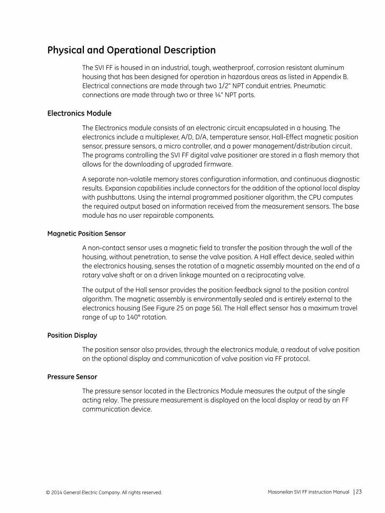
Physical and Operational Description
The SVI FF is housed in an industrial, tough, weatherproof, corrosion resistant aluminum housing that has been designed for operation in hazardous areas as listed in Appendix B. Electrical connections are made through two 1/2" NPT conduit entries. Pneumatic connections are made through two or three ¼" NPT ports.
Electronics Module
The Electronics module consists of an electronic circuit encapsulated in a housing. The electronics include a multiplexer, A/D, D/A, temperature sensor, Hall-Effect magnetic position sensor, pressure sensors, a micro controller, and a power management/distribution circuit. The programs controlling the SVI FF digital valve positioner are stored in a flash memory that allows for the downloading of upgraded firmware.
A separate non-volatile memory stores configuration information, and continuous diagnostic results. Expansion capabilities include connectors for the addition of the optional local display with pushbuttons. Using the internal programmed positioner algorithm, the CPU computes the required output based on information received from the measurement sensors. The base module has no user repairable components.
Magnetic Position Sensor
A non-contact sensor uses a magnetic field to transfer the position through the wall of the housing, without penetration, to sense the valve position. A Hall effect device, sealed within the electronics housing, senses the rotation of a magnetic assembly mounted on the end of a rotary valve shaft or on a driven linkage mounted on a reciprocating valve.
The output of the Hall sensor provides the position feedback signal to the position control algorithm. The magnetic assembly is environmentally sealed and is entirely external to the electronics housing (See Figure 25 on page 56). The Hall effect sensor has a maximum travel range of up to 140° rotation.
Position Display
The position sensor also provides, through the electronics module, a readout of valve position on the optional display and communication of valve position via FF protocol.
Pressure Sensor
The pressure sensor located in the Electronics Module measures the output of the single acting relay. The pressure measurement is displayed on the local display or read by an FF communication device.
Masoneilan SVI FF Instruction Manual =| 23© 2014 General Electric Company. All rights reserved.

Temperature Sensor
A temperature sensor is located in the electronics module and measures ambient temperature. This measurement is used to provide temperature compensation for the position and pressure sensors and other internal electronic components. The temperature is read via the FF communication link to provide a warning of excessive ambient temperature at the positioner.
Output Switch
The SVI FF supports a contact output, SW #1 (Digital Output switch), that can be logically linked to status bits. The Digital Output switch terminal is a solid state contact. The switch requires its own power source and must be connected to the appropriate connector on the Electronics Module Terminal Board. See “Output Switches” on page 66.
© 2014 General Electric Company. All rights reserved.24 | =GE Oil & Gas
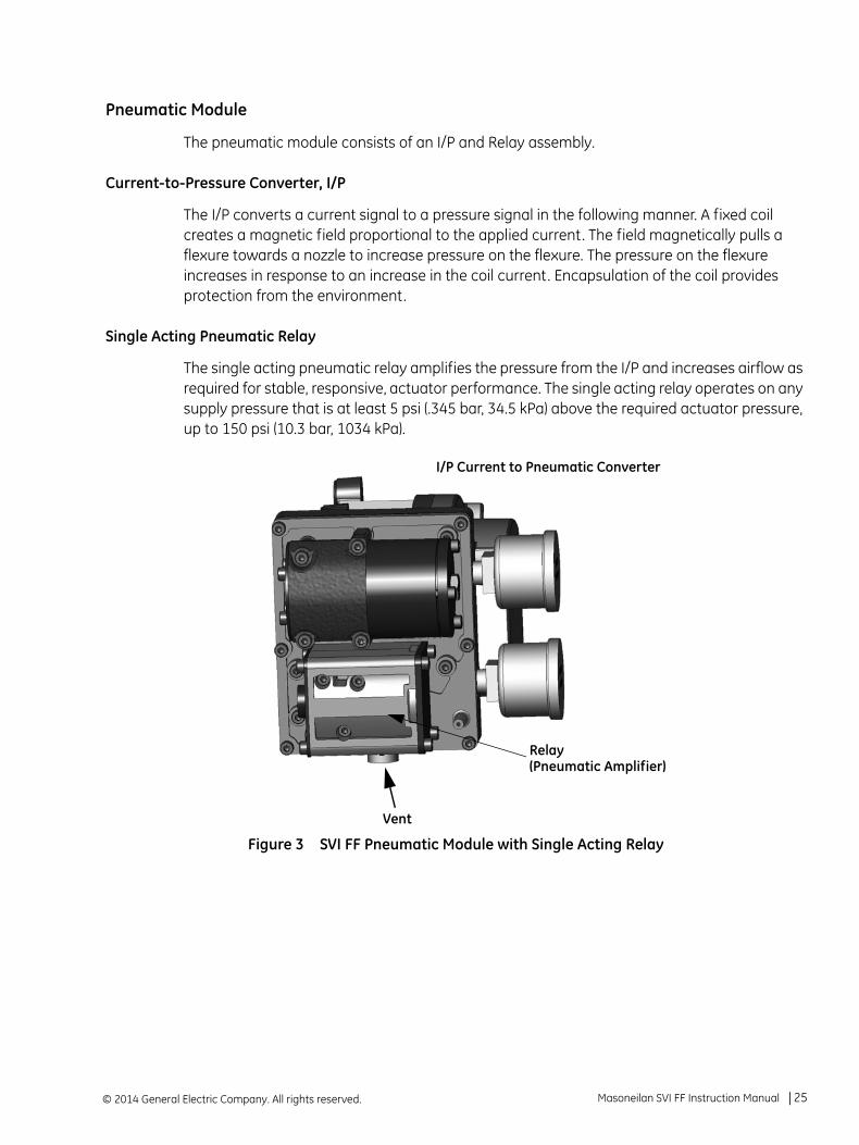
Pneumatic Module
The pneumatic module consists of an I/P and Relay assembly.
Current-to-Pressure Converter, I/P
The I/P converts a current signal to a pressure signal in the following manner. A fixed coil creates a magnetic field proportional to the applied current. The field magnetically pulls a flexure towards a nozzle to increase pressure on the flexure. The pressure on the flexure increases in response to an increase in the coil current. Encapsulation of the coil provides protection from the environment.
Single Acting Pneumatic Relay
The single acting pneumatic relay amplifies the pressure from the I/P and increases airflow as required for stable, responsive, actuator performance. The single acting relay operates on any supply pressure that is at least 5 psi (.345 bar, 34.5 kPa) above the required actuator pressure, up to 150 psi (10.3 bar, 1034 kPa).
Figure 3 SVI FF Pneumatic Module with Single Acting Relay
Vent
Relay (Pneumatic Amplifier)
I/P Current to Pneumatic Converter
Masoneilan SVI FF Instruction Manual =| 25© 2014 General Electric Company. All rights reserved.

SVI FF High Flow
The single acting pneumatic relay amplifies the pressure from the I/P and increases airflow as required for stable, responsive, actuator performance. The single acting relay operates on any supply pressure that is at least 5 psi (.345 bar, 34.5 kPa) above the required actuator pressure, up to 150 psi (10.3 bar, 1034 kPa).
Figure 4 SVI FF High Flow Pneumatic Module with Single Acting Relay
IP Current to Pneumatic Converter
Vent
Relay(Pneumatic Amplifier)
© 2014 General Electric Company. All rights reserved.26 | =GE Oil & Gas

Double Acting Pneumatic Relay
The double acting pneumatic relay amplifies the pressure from the I/P and provides a pair of high flow output signals for operating a double acting cylinder actuator. The double acting relay operates on any supply pressure that is at least 5 psi (.345 bar, 34.5 kPa) above the required actuator pressure, up to 150 psi (10.3 bar, 1034 kPa). The two output pressures may be balanced by means of an adjustable seat assembly. The average of the two pressures is adjusted to equal 70% of the supply pressure. The double acting relay is rated for supply pressure to 150 psi (10.3 bar, 1034 kPa).
Figure 5 Double Acting Pneumatic Relay
Double Acting Supply Pressure Balance
After installation on the actuator, set supply pressure in accordance with actuator specifications. Do not exceed the maximum pressure rating of the actuator. The double acting relay is adjusted at the factory and set to 70% of supply pressure. If adjustment is required consult the factory.
I/P Current to Pneumatic Converter
Double Acting
Vent
Output 2 Gauge
Output 1 Gauge
Output 1 Act 1
Output 2 Act 2
Supply Inlet
Supply Gauge
Relay
Masoneilan SVI FF Instruction Manual =| 27© 2014 General Electric Company. All rights reserved.

Optional Display and Pushbuttons
The optional display and buttons (Figure 6) are mounted on the SVI FF cover plate. The three pushbutton switches operating in conjunction with the display permit reading and modification of the instrument operating parameters without a PC or hand-held communicator. These switches perform generic functions - Increase, Decrease, and Accept by movement through a conventional menu structure, see“Using the Pushbuttons and Digital Interfaces” on page 123.. The switches are operated in a hazardous environment without compromising the flameproof enclosure.
Figure 6 Optional Display
© 2014 General Electric Company. All rights reserved.28 | =GE Oil & Gas
About This Manual
The SVI FF Instruction Manual is intended to help a field engineer install, setup, and calibrate an SVI FF in an efficient manner. This manual also provides in-depth information on SVI FF software, digital interfaces, operation, intrinsic safety configurations, and specifications. If you experience problems that are not documented in this guide contact the factory or your local representative. Sales offices are listed on the back cover of this manual.
Conventions Used in This Manual
Conventions used in this manual are as follows:
Uppercase, italicized letters are used when referencing a term used in the SVI FF display window. For example, when indicating the term mode, as in setup mode, and referring to the display/software operation the convention is to spell mode is all uppercase letters: MODE.
Italics is used for emphasis on important items.
Fields where data is entered or user-entered data is italicized.
Actions performed on buttons, checkboxes, etc. appear bolded. For example: Click Done.
Masoneilan SVI FF Instruction Manual =| 29© 2014 General Electric Company. All rights reserved.

This page intentionally left blank.
3. Quick Start
Step 1: Install the Positioner on the Valve
See:
1. “Pre-Installation Issues” on page 44 before starting.
2. “Mounting the SVI FF on Rotary Valves” on page 49 or “Mounting the SVI FF on Reciprocating Valves” on page 54 or “Installing the SVI FF for Double- Acting Operation” on page 58. Additionally, if using a remote sensor, refer to GEA31195 Masoneilan Valve Solutions Remote Sensor Quick Start .
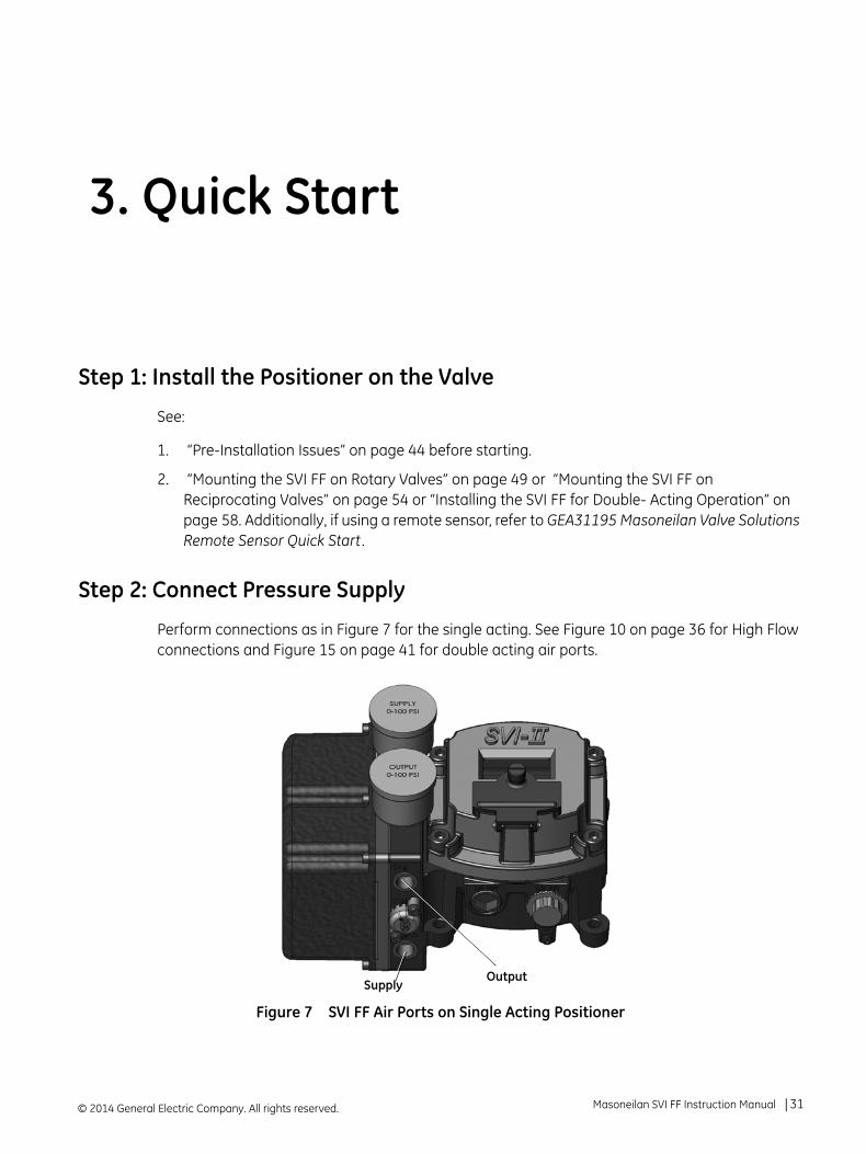
Step 2: Connect Pressure Supply
Perform connections as in Figure 7 for the single acting. See Figure 10 on page 36 for High Flow connections and Figure 15 on page 41 for double acting air ports.
Figure 7 SVI FF Air Ports on Single Acting Positioner
OutputSupply
© 2014 General Electric Company. All rights reserved. Masoneilan SVI FF Instruction Manual =| 31

Step 3: Wire the SVI FF
Perform wiring as per Figure 8.
Figure 8 Connections to Electronics Module (via Terminal Board)
Step 4: Set Tag and Address
Using NI Configurator as an example:
1. Import DD/CFF files.
2. Right-click on the device, select Set Tag, follow the prompts to enter a Tag.
3. Click Set .
Refer to FOUNDATION Fieldbus instructions for shield connections on the FF H1 bus.
Do not navigate to the NI DD folder and copy the DD file onto itself.
Display
Remote
I/P Connector
Position Sensor
Configuration LockJumper
9 - 32 V Foundation Fieldbus
Discrete Out
Input
Digital Input
AI PV 1-5 VDC (Not Used in this release)
Shield(on FF unit
Input Signal(polarity independent)
housing)
NOTE
CAUTION
© 2014 General Electric Company. All rights reserved.32 | =GE Oil & Gas

4. Right-click on the device, select Set Address, follow the prompts to enter an Address.
5. Click Set .
Step 5: Basic Configuration
This section serves as an example where the AO block and TB block are configured. However, there are a number of combinations that can be configured. This discussion is valid if the positioner is controlled by the AO block.
1. For the Transducer block set:
ACTUATOR_3.ACT_FAIL_ACTION_1 = either 1. Valve Closed (most common) or 2. Valve Open
ACCESSORY.REMOTE_SENSOR = 0, if remote sensor is not in use (internal Hall sensor is used - most common)
ACTIVATE_CONTROL_SET to one of:
Do not deactivate the Set to OOS mode checkbox. The block must be in OOS to change the Tag.
If the device is at the defauult address range (248 (0xF8)- 251 (OxFB)), you must set the address outside of that range.
Do not deactivate the Set to OOS mode checkbox. The block must be in OOS to change the Address.
0: Activate Custom Con-trol Set (required for Autotune as well - most common)
1: Activate Control Set 1 (Slowest)
2: Activate Control Set 2
CAUTION
CAUTION
CAUTION
Masoneilan SVI FF Instruction Manual =| 33© 2014 General Electric Company. All rights reserved.
CHAR_SELECTION.TYPE to one of:
See “Transducer Block Parameters” on page 143. for further settings.
2. For the AO block set as below:
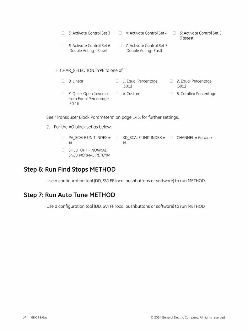
Step 6: Run Find Stops METHOD
Use a configuration tool (DD, SVI FF local pushbuttons or software) to run METHOD.
Step 7: Run Auto Tune METHOD
Use a configuration tool (DD, SVI FF local pushbuttons or software) to run METHOD.
3: Activate Control Set 3 4: Activate Control Set 4 5: Activate Control Set 5 (Fastest)
6: Activate Control Set 6 (Double Acting - Slow)
7: Activate Control Set 7 (Double Acting- Fast)
0. Linear 1. Equal Percentage (30:1)
2. Equal Percentage (50:1)
3. Quick Open (reversal from Equal Percentage (50:1))
4. Custom 5. Camflex Percentage
PV_SCALE.UNIT INDEX = %
XD_SCALE.UNIT INDEX = %
CHANNEL = Position
SHED_OPT = NORMAL SHED NORMAL RETURN
© 2014 General Electric Company. All rights reserved.34 | =GE Oil & Gas
4. Mechanical Installation
Overview
The SVI FF single acting (Figure 11 on page 37) and double acting (Figure 16 on page 42) are high performance, digital valve positioners that combine a local display with remote communication and diagnostic capabilities. The SVI FF is available with a variety of options to fulfill diverse applications.
SVI FF Positioner Types
SVI FF positioner types include:
“Single Acting Positioner Description” on page 35, including a high flow version
“Double Acting Positioner Description” on page 41
Single Acting Positioner Description
The supply and output connections for the SVI FF (Figure 9), located on bottom of the pneumatic block, are tapped 1⁄4" NPT. Output is toward the front, supply is toward the back. Two pressure gauges, output on top, supply on bottom, are located on the front of the pneumatic block.
The supply and output connections for the SVI FF High Flow (Figure 10), located on bottom and leftside of the pneumatic block, are tapped 1⁄2" NPT.
Maximum allowable air supply pressure to the SVI FF varies according to actuator, valve size, and valve type. See Pressure Drop tables in valve specification sheets to determine the correct positioner supply pressure. Minimum supply pressure should be 5 psi to 10 psi (.345 bar - .69 bar) (34.485 - 68.97 kPa) above maximum spring range but cannot exceed the rated actuator pressure.
Prior to beginning the installation process review the “Safety Information” on page 9..
NOTE
© 2014 General Electric Company. All rights reserved. Masoneilan SVI FF Instruction Manual =| 35

Figure 9 SVI FF Air Ports on Single Acting Positioner
Figure 10 SVI FF High Flow Air Ports on Single Acting Positioner
OutputSupply
OutputSupply
© 2014 General Electric Company. All rights reserved.36 | =GE Oil & Gas

Figure 11 SVI FF Single Acting Components
SVI FF CoverSVI FF Single Acting Assembled
ElectronicsModule
Pneumatic Train andCover (I/P Module,Relay)
I/P
Manifold
Relay
Masoneilan SVI FF Instruction Manual =| 37© 2014 General Electric Company. All rights reserved.

Figure 12 SVI FF High Flow Components
SVI FF CoverSVI FF High Flow Assembled
ElectronicsModule
Pneumatic Train andCover (I/P Module,Relay)
I/P
Manifold
Relay
© 2014 General Electric Company. All rights reserved.38 | =GE Oil & Gas

SVI FF Single Acting and High Flow Dimensions
Figure 13 illustrates the SVI FF single-acting dimensions.
Figure 13 SVI FF Single-Acting Dimensions
Masoneilan SVI FF Instruction Manual =| 39© 2014 General Electric Company. All rights reserved.

Figure 14 illustrates the SVI FF high flow dimensions.
Figure 14 SVI FF High Flow Dimensions
© 2014 General Electric Company. All rights reserved.40 | =GE Oil & Gas

Double Acting Positioner Description
The Double Acting (DA) relay has a pair of opposed pneumatic outputs. When Output 1 delivers air to one side of the actuator, Output 2 vents air from the opposite side of the actuator piston. The volume of air trapped in each determines the position of the actuator.
The Action (ATO or ATC) is applied with respect to Output 1. When Output 1 is connected to deliver air to extend the actuator, the action is ATC, on a down-seating valve.
Figure 15 Air Ports on Double Acting Positioner
Balance Pressure
The double-acting relay is designed to deliver pressure on both sides of a piston type actuator, so that the cylinder can provide the required thrust and stiffness. This stiffness is factory adjusted to 70% of the supply pressure. This means that, without any unbalance forces from the valve stem, both outputs deliver roughly 70% of air supply pressure.
Although it is not recommended, the stiffness can be adjusted by moving the Adjustable Seat assembly up or down.
Output ISupply Output II
Masoneilan SVI FF Instruction Manual =| 41© 2014 General Electric Company. All rights reserved.
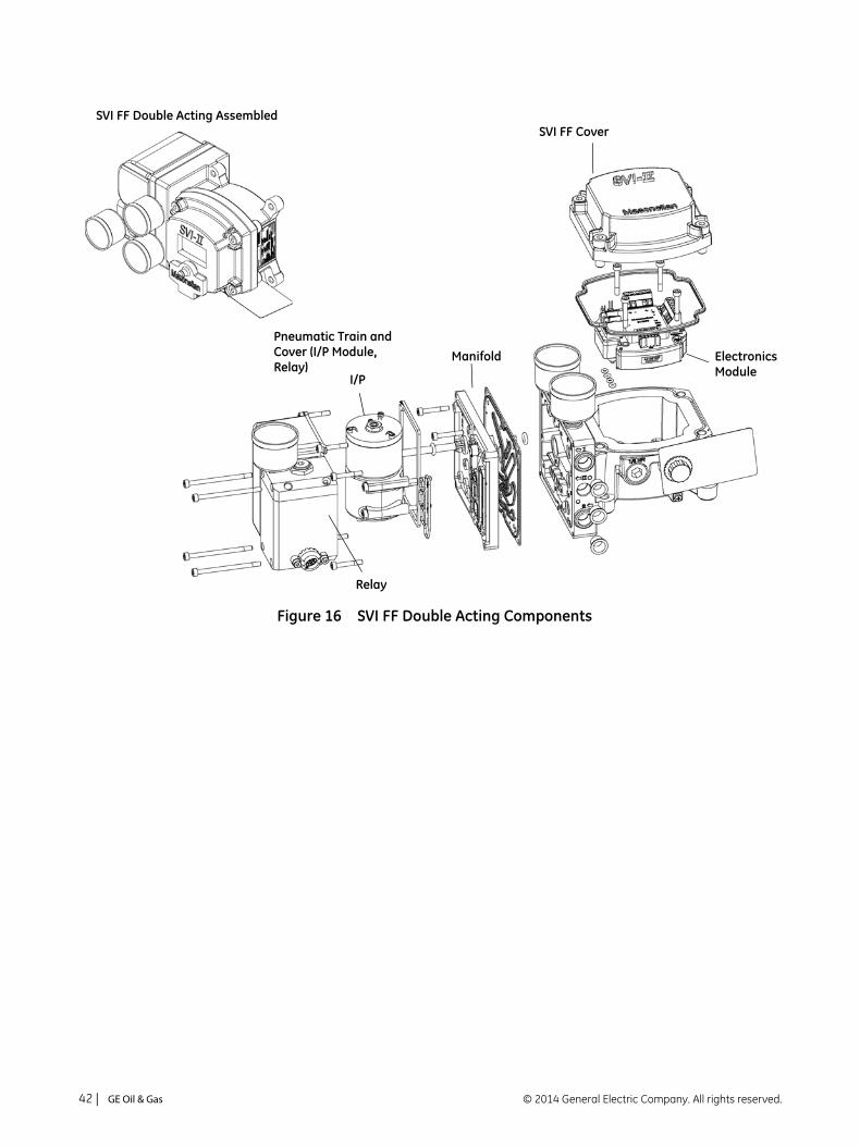
Figure 16 SVI FF Double Acting Components
SVI FF CoverSVI FF Double Acting Assembled
ElectronicsModule
I/P
Manifold
Relay
Pneumatic Train andCover (I/P Module,Relay)
© 2014 General Electric Company. All rights reserved.42 | =GE Oil & Gas

SVI FF Double Acting Dimensions
Figure 17 illustrates the SVI FF double-acting dimensions.
Figure 17 SVI FF Double-Acting Dimensions
Masoneilan SVI FF Instruction Manual =| 43© 2014 General Electric Company. All rights reserved.

Installation
This section discusses:
“Pre-Installation Issues” on page 44
“Installation Steps” on page 45
“Installation Notes” on page 46
“Mounting the SVI FF on Rotary Valves” on page 49
“Mounting the SVI FF on Reciprocating Valves” on page 54
“Installing the SVI FF for Double- Acting Operation” on page 58
“Connecting the Tubing and Air Supply” on page 61
“Wiring the SVI FF” on page 64
Pre-Installation Issues
Storage
If the SVI FF is stored for a long duration, you must keep the housing sealed against weather, fluids, particles, and insects. To prevent damage to the SVI FF:
Use the plugs provided with shipment to plug the ¼ NPT air connections, on the positioner and on the air filter regulator set.
Do not allow standing water to accumulate.
Observe storage temperature requirements.
Unpacking
Exercise care when unpacking the control valve and its mounted accessories. The SVI FF container includes a CD-ROM with ValVue Standard Version and a CD containing translated documents for installing the device in areas where there is a potential for explosive gas atmospheres.
© 2014 General Electric Company. All rights reserved.44 | =GE Oil & Gas

Installation Steps
If you experience problems that are not documented in this guide call the factory or your local representative. Sales offices are listed on the last page of this document.
The steps necessary to complete the SVI FF installation and software setup are outlined in Table 1.
Refer to “Output Switch” on page 24 for guidelines on safely wiring switch load limits.
Table 1 SVI FF Installation Steps
Step No. Procedure Reference
1 Attach mounting bracket to the actuator. See page 49 for rotary valve and page 54 for reciprocating valve instructions.
2 Install the SVI FF magnetic assembly (rotary valves only). See page 53 for instructions.
3 Assemble the SVI FF on the bracket that is mounted to the valve actuator.
See page 49 for rotary valve and page 54 for reciprocating valve instructions.
4 Install the Remote Position Sensor, if necessary. See GEA31195 Masoneilan Valve Solutions Remote Sensor Quick Start for instructions.
5 Connect the pneumatic tubing to the SVI FF. See page 61 for instructions.
6 Connect the air supply to the SVI FF. See page 62 for instructions.
7 Connect the positioner to the FF Control Loop segment by installing the SVI FF wiring.
See page 65 for instructions.
8 Configure/Calibrate using LCD Pushbutton display See page 124 for instructions
Configure/Calibrate using a Hand Held Communicator. See page 127 for instructions
Configure/Calibrate using ValVue See page 129 for instructions.
Failure to adhere to the requirements listed in this manual can cause loss of life and property. Before installing, using, or carrying out any maintenance tasks associated with this instrument, READ THE INSTRUCTIONS CAREFULLY.
CAUTION
WARNING
Masoneilan SVI FF Instruction Manual =| 45© 2014 General Electric Company. All rights reserved.

Installation Notes
The installation must comply with local and national regulations concerning the compressed air supply and the SVI FF instrument.
Installation and maintenance must be performed only by qualified personnel. Repairs to the SVI FF beyond the scope of this manual must be performed by the factory.
Area Classification, Protection Type, Temperature Class, Gas Group, and Ingress protection must conform to the data indicated on the label.
Wiring and conduit must conform to all local and national codes governing the installation. Wiring must be rated for at least 85º C (185º F) or 5º C (41º F) above maximum ambient, whichever is greater.
Approved wire seals against ingress of water and dust are required and the 1/2" NPT fittings must be sealed with tape or pipe dope in order to meet the highest level of ingress protection.
To avoid injury or the process being affected when installing or replacing a positioner on a control valve, ensure that:
If the valve is located in a hazardous area make sure the area has been certified as safe or that all electrical power to the area has been disconnected before removing any covers or disconnecting any leads.
Shut off air supply to the actuator and to any valve mounted equipment.
Ensure the valve is isolated from the process by either shutting off the process or using bypass valves for isolation. Tag shutoff or bypass valves to guard against a turn-on while work is in progress.
Purge air from actuator and check that valve is in its unenergized position.
© 2014 General Electric Company. All rights reserved.46 | =GE Oil & Gas

Control Sets Configuration
Table 2 and Table 3 give guidelines for configuring various actuator sizes with corresponding control sets. Table 4 lists the FF parameters.
Table 2 Actuator Settings: Control Sets for Single Acting
Set # Actuator Size
Examples
1 Small 4.5" Camflex (7-15 Spring Range)
2
#6, 87(ATC), 3-15 Spring Range
#6, 88(ATO), 11-23 Spring Range
#10, 87 (ATC), 3-15 Spring Range
#10, 88(ATO), 11-23 Spring Range
3
#6, 87(ATC), 6-30 Spring Range
#6, 88(ATO), 21-45 Spring Range
#10, 87 (ATC), 6-30 Spring Range
#10, 88(ATO), 21-45 Spring Range
4
#16, 87(ATC), 3-15 Spring Range
#16, 88(ATO), 11-23 Spring Range
#23, 87 (ATC), 3-15 Spring Range
#23, 88(ATO), 11-23 Spring Range
5 Large
#16, 87(ATC), 6-30 Spring Range
#16, 88(ATO), 21-45 Spring Range
#23, 87 (ATC), 6-30 Spring Range
#23, 88(ATO), 21-45 Spring Range
Table 3 Actuator Settings: Control Sets for Double Acting
Set # Actuator Size
Examples
6 Small
51, #12, Rated Travel 3.75"
51, #16, Rated Travel 2"
51, #20, Rated Travel 1.25"
7 Large
51, #12, Rated Travel = 4"
51, #16, Rated Travel 2.5"
51, #20, Rated Travel 1.5"
Model 70 Camflex, Double Acting, #10
Masoneilan SVI FF Instruction Manual =| 47© 2014 General Electric Company. All rights reserved.
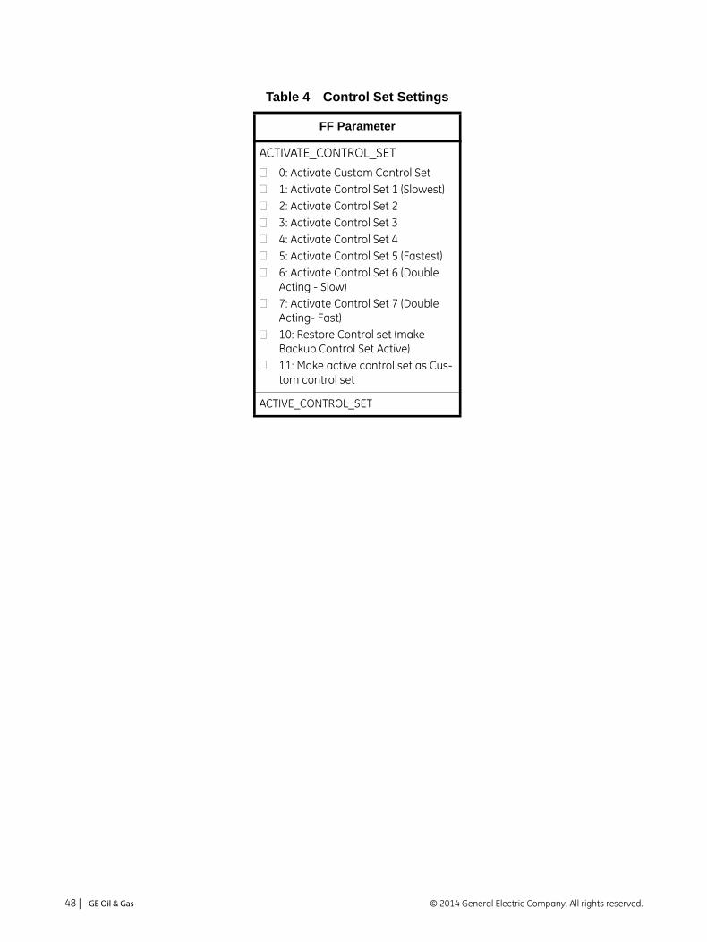
Table 4 Control Set Settings
FF Parameter
ACTIVATE_CONTROL_SET
0: Activate Custom Control Set 1: Activate Control Set 1 (Slowest)2: Activate Control Set 23: Activate Control Set 34: Activate Control Set 45: Activate Control Set 5 (Fastest)6: Activate Control Set 6 (Double Acting - Slow)7: Activate Control Set 7 (Double Acting- Fast)10: Restore Control set (make Backup Control Set Active)11: Make active control set as Cus-tom control set
ACTIVE_CONTROL_SET
© 2014 General Electric Company. All rights reserved.48 | =GE Oil & Gas

Mounting the SVI FF on Rotary Valves
This procedure is used to mount the SVI FF on rotary control valves that have less than 60° rotation, such as a Camflex or a Varimax. For valves that have rotation greater than 60° refer to “Rotary - 90°” on page 53.
Required Tools
The following tools are needed to complete the rotary valve installation:
3⁄16" Hex Key with tee handle
5⁄32" Hex Key
3 mm, 4 mm, 5 mm Hex Key
7⁄16" Wrench
To mount the SVI FF:
1. Attach the SVI FF rotary mounting bracket to the valve actuator using two (2) 5⁄16 - 18 UNC flat-head cap screws. Mount the SVI FF as shown in Figure 18, ATO or in Figure 19 on page 50, ATC. In the preferred mounting position, the long end of the mounting bracket is on your left when facing the actuator, for any position of the valve and actuator.
Figure 18 Camflex Air-To-Open Mounting (Front View)
Masoneilan SVI FF Instruction Manual =| 49© 2014 General Electric Company. All rights reserved.
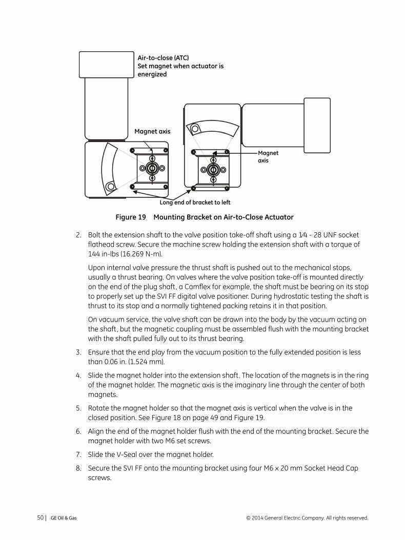
Figure 19 Mounting Bracket on Air-to-Close Actuator
2. Bolt the extension shaft to the valve position take-off shaft using a 1⁄4 - 28 UNF socket flathead screw. Secure the machine screw holding the extension shaft with a torque of 144 in-lbs (16.269 N-m).
Upon internal valve pressure the thrust shaft is pushed out to the mechanical stops, usually a thrust bearing. On valves where the valve position take-off is mounted directly on the end of the plug shaft, a Camflex for example, the shaft must be bearing on its stop to properly set up the SVI FF digital valve positioner. During hydrostatic testing the shaft is thrust to its stop and a normally tightened packing retains it in that position.
On vacuum service, the valve shaft can be drawn into the body by the vacuum acting on the shaft, but the magnetic coupling must be assembled flush with the mounting bracket with the shaft pulled fully out to its thrust bearing.
3. Ensure that the end play from the vacuum position to the fully extended position is less than 0.06 in. (1.524 mm).
4. Slide the magnet holder into the extension shaft. The location of the magnets is in the ring of the magnet holder. The magnetic axis is the imaginary line through the center of both magnets.
5. Rotate the magnet holder so that the magnet axis is vertical when the valve is in the closed position. See Figure 18 on page 49 and Figure 19.
6. Align the end of the magnet holder flush with the end of the mounting bracket. Secure the magnet holder with two M6 set screws.
7. Slide the V-Seal over the magnet holder.
8. Secure the SVI FF onto the mounting bracket using four M6 x 20 mm Socket Head Cap screws.
Air-to-close (ATC)Set magnet when actuator is energized
Magnet axis
Magnet axis
Long end of bracket to left
© 2014 General Electric Company. All rights reserved.50 | =GE Oil & Gas

9. Ensure no interference exists with the position sensor protrusion.
10. Ensure that the V-Seal makes contact with the skirt around the position sensor protrusion on the SVI FF housing.
Figure 20 Camflex with Mounting Bracket (Side View)
Lock magnet assembly
Flush w/top of bracket
Extension shaft
Magnet holder
V-seal
Masoneilan SVI FF Instruction Manual =| 51© 2014 General Electric Company. All rights reserved.

Table 5 shows the general guidelines for travel sensor alignment. Review the table prior to installing the SVI FF on a rotary valve actuator for proper alignment of the magnet. Proper alignment is required for proper Hall sensor operation.
Table 5 Travel Sensor Alignment
Rotary Mounting
System
Stroke Direction Magnet Orientation
Valve Position
Sensor Counts (TB: RAW_POSITION)
Rotary <60° Rotation
Clockwise or counter-clockwise rotation
(0°)
Closed (0%) 0 +/- 1000
>60° Rotation
Clockwise with increasing setpoint
(-45°)
Full Open
or
Full Closed
-8000 +/- 1500
or
+8000 +/- 1500
>60° Rotation
Counter clockwise rotation with increasing setpoint
(+45°)
Full Open
or
Full Closed
-8000 +/- 1500
or
+8000 +/- 1500
General Rule for other configu-rations
Any amount of rotation clockwise or counterclockwise
(0°)
50% Travel
(Mid-Stroke)
0 +/- 1000
© 2014 General Electric Company. All rights reserved.52 | =GE Oil & Gas
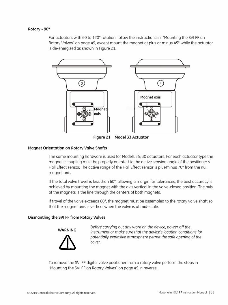
Rotary - 90°
For actuators with 60 to 120° rotation, follow the instructions in “Mounting the SVI FF on Rotary Valves” on page 49, except mount the magnet at plus or minus 45° while the actuator is de-energized as shown in Figure 21.
Figure 21 Model 33 Actuator
Magnet Orientation on Rotary Valve Shafts
The same mounting hardware is used for Models 35, 30 actuators. For each actuator type the magnetic coupling must be properly oriented to the active sensing angle of the positioner’s Hall Effect sensor. The active range of the Hall Effect sensor is plus⁄minus 70° from the null magnet axis.
If the total valve travel is less than 60°, allowing a margin for tolerances, the best accuracy is achieved by mounting the magnet with the axis vertical in the valve-closed position. The axis of the magnets is the line through the centers of both magnets.
If travel of the valve exceeds 60°, the magnet must be assembled to the rotary valve shaft so that the magnet axis is vertical when the valve is at mid-scale.
Dismantling the SVI FF from Rotary Valves
To remove the SVI FF digital valve positioner from a rotary valve perform the steps in “Mounting the SVI FF on Rotary Valves” on page 49 in reverse.
Before carrying out any work on the device, power off the instrument or make sure that the device’s location conditions for potentially explosive atmosphere permit the safe opening of the cover.
Magnet axis
Magnet axis
WARNING
Masoneilan SVI FF Instruction Manual =| 53© 2014 General Electric Company. All rights reserved.

Mounting the SVI FF on Reciprocating Valves
This section describes the procedure for mounting the SVI FF on Reciprocating Valves (using Masoneilan’s 87⁄88 Multi-Spring actuators as an example).
Tools required:
7⁄16" Combination Wrench (2 required)
3⁄8" Combination Wrench
1⁄2" Combination Wrench
Phillips Head Screw Driver
5 mm Hex Key Wrench
Mounting the SVI FF on a Reciprocating Actuator
1. Ensure that the lever is pinned to the magnet assembly and held securely by an M5 flat head screw to ensure that the magnet axis is vertical when the lever is in the valve closed position. Tighten the lever screw securely.
2. Mount the SVI FF reciprocating mounting bracket to the actuator using two (2) 5⁄16 - 18 UNC cap screws. The mounting location of the bracket depends on the size and stroke of the actuator. Refer to Figure 22 and Table 6 on page 56.
Figure 22 Reciprocating Valve Mounting Bracket
3. Select mounting hole A, B, C or D for the stroke of the valve. For example, hole B is shown in Figure 23 on page 55 for a size 10 actuator with 1.0" stroke. Unless otherwise specified, the SVI FF mounting assumes that the actuator is in the normal upright position. The mounting hole in the slotted opening of the mounting bracket must be left when facing the actuator, with the actuator in the upright position.
© 2014 General Electric Company. All rights reserved.54 | =GE Oil & Gas
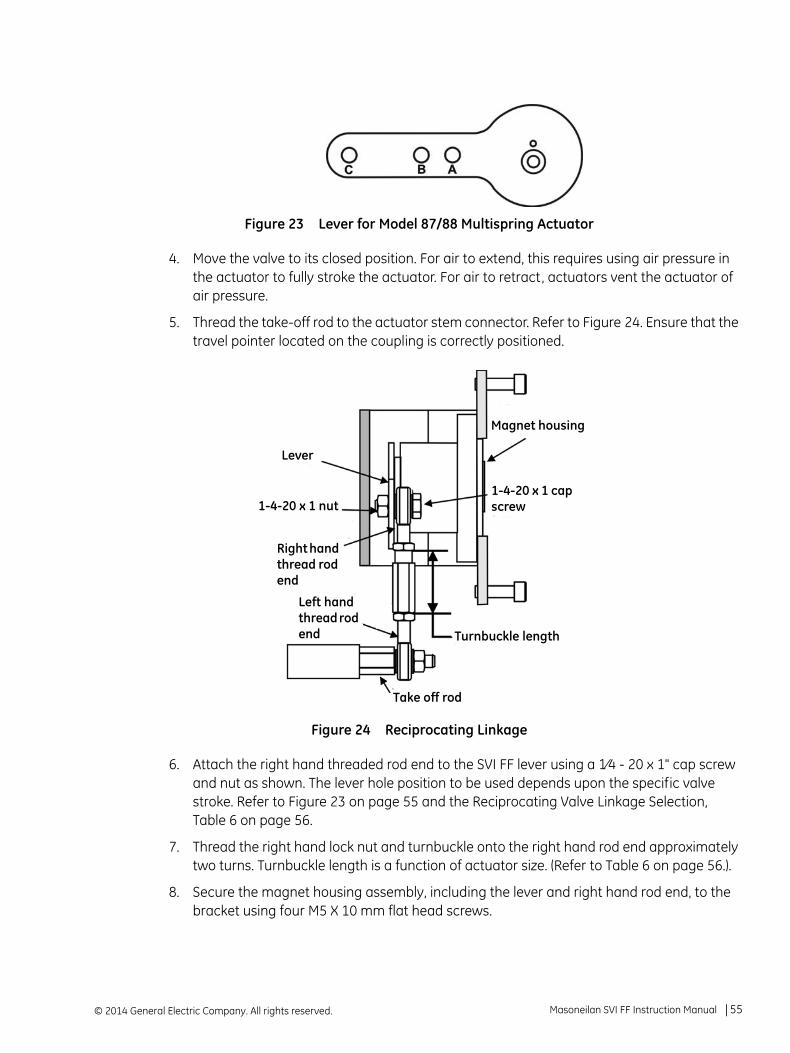
Figure 23 Lever for Model 87/88 Multispring Actuator
4. Move the valve to its closed position. For air to extend, this requires using air pressure in the actuator to fully stroke the actuator. For air to retract, actuators vent the actuator of air pressure.
5. Thread the take-off rod to the actuator stem connector. Refer to Figure 24. Ensure that the travel pointer located on the coupling is correctly positioned.
Figure 24 Reciprocating Linkage
6. Attach the right hand threaded rod end to the SVI FF lever using a 1⁄4 - 20 x 1" cap screw and nut as shown. The lever hole position to be used depends upon the specific valve stroke. Refer to Figure 23 on page 55 and the Reciprocating Valve Linkage Selection, Table 6 on page 56.
7. Thread the right hand lock nut and turnbuckle onto the right hand rod end approximately two turns. Turnbuckle length is a function of actuator size. (Refer to Table 6 on page 56.).
8. Secure the magnet housing assembly, including the lever and right hand rod end, to the bracket using four M5 X 10 mm flat head screws.
Lever
1-4-20 x 1 nut
Right hand thread rod end
Left hand thread rod end Turnbuckle length
Magnet housing
1-4-20 x 1 cap screw
Take off rod
Masoneilan SVI FF Instruction Manual =| 55© 2014 General Electric Company. All rights reserved.

9. Attach the left hand threaded rod end to the take-off rod with 1⁄4 - 20 UNC nut and thread the left hand lock nut onto the rod end.
10. Thread the turnbuckle onto the left hand threaded rod end. Refer to Figure 24 on page 55.
11. Adjust the turnbuckle until the hole in the SVI FF lever is aligned with the indicating hole in the bracket. Tighten both turnbuckle lock nuts. See Figure 22 on page 54.
12. Mount the SVI FF to the bracket and secure with four M6 socket head cap screws.
Figure 25 Magnet Holder for Reciprocating Valves
Table 6 Reciprocating Valve Mounting Hole and Turnbuckle Length
Actuator SizeMasoneilan
Stroke Mounting Hole Lever Hole Turnbuckle Length
6 and 10 0.5 - 0.8"(12.7 - 20.32 mm)
A A 1.25"(31.75 mm)
10 0.5 - 0.8"
(12.7 - 20.32 mm)
A A 1.25"(31.75 mm)
10 >0.8 – 1.5"(20.32 - 38.1 mm)
B B 1.25"(31.75 mm)
16 0.5 - 0.8"(12.7 - 20.32 mm)
B A 2.90"(73.66 mm)
16 >0.8 – 1.5"(20.32 - 38.1 mm)
C B 2.90"(73.66 mm)
16 >1.5 – 2.5"(38.1 - 63.5 mm)
D C 2.90"(73.66 mm)
Lever
Magnet holder assembly
Housing
Magnets
Ring
© 2014 General Electric Company. All rights reserved.56 | =GE Oil & Gas

Dismantling the SVI FF from Reciprocating Valves
To remove the SVI FF digital valve positioner from a reciprocating valve perform the steps in “Mounting the SVI FF on Reciprocating Valves” on page 54 in reverse.
23 0.5 - 0.8"(12.7 - 20.32 mm)
B A 5.25"(133.35 mm)
23 >0.8 – 1.5"(20.32 - 38.1 mm)
C B 5.25"(133.35 mm)
23 >1.5 – 2.5"(38.1 - 63.5 mm)
D C 5.25"(133.35 mm)
Before carrying out any work on the device, power off the instrument or make sure that the device’s location conditions for potentially explosive atmosphere permit the safe opening of the cover.
Table 6 Reciprocating Valve Mounting Hole and Turnbuckle Length (Continued)
Actuator SizeMasoneilan
Stroke Mounting Hole Lever Hole Turnbuckle Length
WARNING
Masoneilan SVI FF Instruction Manual =| 57© 2014 General Electric Company. All rights reserved.

Installing the SVI FF for Double- Acting Operation
This section explains how to mount the SVI FF for the 84/85/86 kit for double-acting valve positioner configurations.
To mount the kit:
1. Set valve to the closed position.
2. Install the mounting assembly to the yoke (Figure 26) using helical spring washer 5/16, flat washer 5/16 and hex screw 5/16-18x44.5 [1.75] LG.
Figure 26 85/86 Valve
3. Set rod-ends and brackets to stroke and size of actuator. The default setting is a 4.00” stroke. Other stroke settings are as in Figure 27.
Figure 27 Stroke Settings
Mount all components snug enough to stay in place but loose enough to tap with rubber hammer into final position.
Lever
Rod-endKit MountBracket
NOTE
Hole A: .50" to .80"
Hole B: 1.00" to 1.50"
Hole C: 2.00" to 2.50"
Hole D: 3.00" to 4.50"
Hole E: 5.00" to 6.00"
© 2014 General Electric Company. All rights reserved.58 | =GE Oil & Gas

4. Mount take-off bracket to stem block at angle which keeps turnbuckle assembly parallel to stem (Figure 28) using:
a. For top: two plain 5/16 flat washers, helical spring washer 5/16, two hex nuts 5/16-18 regular.
b. For bottom: hex nut regular 1/4-20 and hex screw 1/4-20 UNC x 22.2 [.88] LG.
Figure 28 Bracket Configuration Strokes .5 - 2.50” and 3-6”
5. Ensure the turnbuckle assembly is parallel to the stem and the magnets are in the valve closed position (Figure 29) and connect to take-off bracket.
Figure 29 Magnet Position with Valve Closed
2.00" to 2.50" stroke
.50" to 1.50" stroke
Bracket configurationStrokes .50" to 2.50"
3.00" to 6.00" stroke
Bracket configurationStrokes 3.00" to 6.00"
Position of magnets with valve closed
Masoneilan SVI FF Instruction Manual =| 59© 2014 General Electric Company. All rights reserved.

6. Verify lever is in correct position with valve closed. Adjust rod-ends, if necessary.
Figure 30 Lever Alignment
7. Mount the SVI FF with M6-1 screws.
8. Cycle the valve open to close verifying proper components movement and that rod-ends move free and clear from other components.
Align lever to edge
© 2014 General Electric Company. All rights reserved.60 | =GE Oil & Gas

Connecting the Tubing and Air Supply
The last step in hardware installation for the SVI FF is to connect the air supply to the positioner. This section describes the process for connecting the tubing and air supply to a single and double acting positioner.
The use of a Masoneilan filter regulator with a 5-micron filter is recommended for the air supply. Use 1⁄4" (6.35 mm) minimum tubing between filter regulator, the SVI FF and the actuator, with 3⁄8" (9.53 mm) used for larger actuators. Use a soft setting anaerobic hydraulic seal such as Loctite Hydraulic Seal 542 for sealing the pneumatic pipe threads. Follow manufacturer’s instructions.
1. Install the tubing to the air supply port, S(arrow only for High Flow).
2. For a
Single acting actuator - pipe the outbound air from the output pressure port (I) to the actuator (arrow only for High Flow).
Double acting actuator - pipe output pressure port one (I) for one side of the actuator and output pressure port two (II) for the other side of the actuator (arrow only for High Flow).
3. Air supply:
Supply pressure for the single acting SVI FF: 20 -150 psi max. (1.4 - 10.3 bar) (138 - 1034 kPa)
Supply pressure for the double acting and FF High Flow SVI FF: 25 - 150 psi (1.73 - 10.3 bar) (172 - 1034 kPa)
Minimum tubing diameter 1⁄4" (6mm x 4mm)
Supply pressure must be 5 psi - 10 psi (.345 bar - .69 bar) (34.485 - 68.97 kPa) greater than the spring range of the actuator but may not exceed the rated actuator pressure. Refer to the valve or actuator instruction manual.
Isolate the valve from the process and disconnect air tubing from the positioner. Disconnect air fully to avoid injury or process damage.
Maximum allowable air supply pressure to the SVI FF varies according to actuator and valve size and type. See pressure drop tables in valve specification sheets to determine correct positioner supply pressure. Minimum supply pressure should be 5 to 10 psi (.345 bar - .69 bar) (34.485 - 68.97 kPa) above maximum spring pressure.
WARNING
NOTE
Masoneilan SVI FF Instruction Manual =| 61© 2014 General Electric Company. All rights reserved.

For High Flow installations above 125 psi (8.6 bar, 861 kPa), perform a manual find stops and use preset tuning, especially with large volume actuators. If possible, use a Quick Exhaust.
The SVI FF Digital Valve Positioner is designed to operate with clean, dry, oil-free, instrument grade air to ANSI-ISA-57.3 1975 (R1981) or ISA-S7.3-1975 (R1981) or with a sweet natural gas supply (SVI FF models SVI FF-2 through SVI FF-3).
Table 7 Air Supply Requirements
Dew Point At least 18° F (-7° C) below minimum anticipated ambient temperature
Particulate Matter Filtered to 5 microns
Oil Content Less than 1 ppm w/w
Contaminants Free of all corrosive contaminants
The SVI FF High Flow digital valve positioner cannot be placed in parallel with another volume booster. Contact the factory for further instructions regarding configuration with boosters as well as other non-standard configurations.
Do not use pipe thread sealant tape on pneumatic fittings. It may shred into small particles that can cause instrument malfunction.Remove any excess pipe thread sealant from the first and second threads to prevent uncured sealant from entering the air lines.
Never exceed the actuator maximum rated supply pressure: 150 psi (10.3 bar, 1030 kPa). Damage to equipment or injury to personnel can result.
CAUTION
NOTE
CAUTION
WARNING
© 2014 General Electric Company. All rights reserved.62 | =GE Oil & Gas
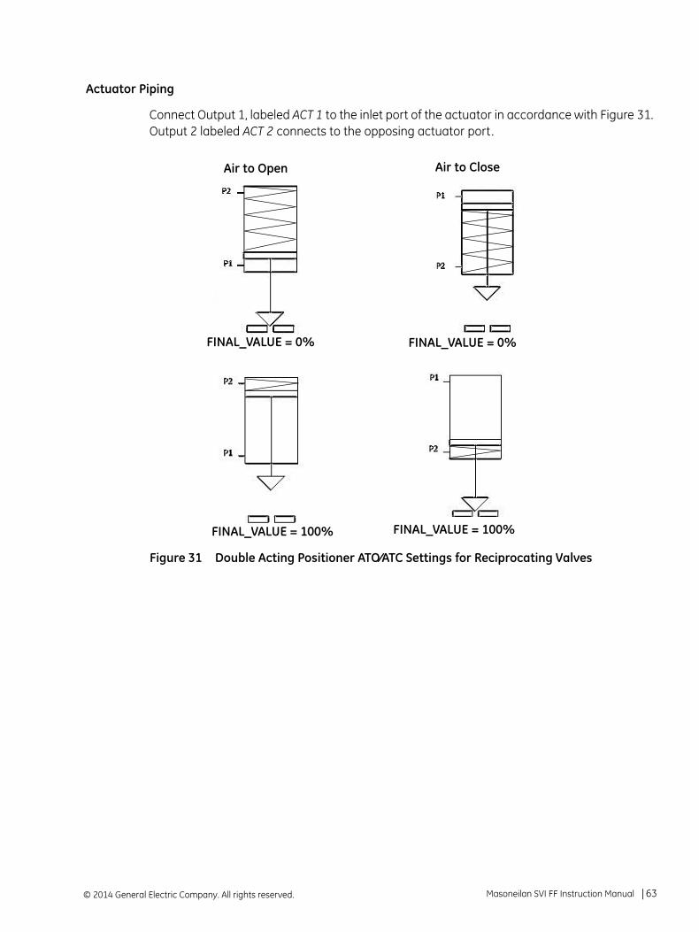
Actuator Piping
Connect Output 1, labeled ACT 1 to the inlet port of the actuator in accordance with Figure 31. Output 2 labeled ACT 2 connects to the opposing actuator port.
Figure 31 Double Acting Positioner ATO⁄ATC Settings for Reciprocating Valves
Air to Open
FINAL_VALUE = 0%
FINAL_VALUE = 100%
Air to Close
FINAL_VALUE = 0%
FINAL_VALUE = 100%
Masoneilan SVI FF Instruction Manual =| 63© 2014 General Electric Company. All rights reserved.

Wiring the SVI FF
The procedure below outlines wiring the SVI FF.
Comply with current national and local regulations for electrical installation work.
Comply with national and local explosive atmosphere regulations.
Before carrying out any work on the device, power off the instrument or make sure that the local conditions for potentially explosive atmosphere permit the safe opening of the cover.
Refer to “Output Switch” on page 24 for guidelines on safely wiring switch load limits.
WARNING
CAUTION
© 2014 General Electric Company. All rights reserved.64 | =GE Oil & Gas

Connecting to the Control Loop
The SVI FF digital valve positioner MUST BE grounded according to local regulations. Physically connect the SVI FF to the control loop using a cable specified by the FF Foundation. A shielded cable is recommended.
To communicate using FF:
1. Connect one end of the cable to the control loop's 9 - 32 VDC output.
2. Remove the threaded wiring covers on the positioner.
3. Connect the other end of the cable to the SVI FF. There are two threaded openings on the positioner. Use the opening with the red plastic insert.
Figure 32 Connections to Electronics Module (via Terminal Board)
Making Connections to the Terminal Board
Connect the wires from the option as follows (wire size 12 to 22 AWG on the 9 - 32 VDC FF input and 14 to 26 AWG on the PV, SW, DI, and Remote):
1. If the wires have not been stripped, strip approximately 1/4 in (6.35 mm) of the insulation at the end of wires.
2. Locate the correct terminal block on the terminal board (see Figure 32).
3. Loosen the screw until the opening is sufficient for wire insertion.
4. Insert the wire into the opening and retighten the screw.
Display
Remote
I/P Connector
Position Sensor
Configuration LockJumper
9 - 32 V Foundation Fieldbus
Discrete Out
Input
Digital Input
AI PV 1-5 VDC (Not Used in this release)
GroundShield(on FF unit
Input Signal(polarity independent)
housing)
Masoneilan SVI FF Instruction Manual =| 65© 2014 General Electric Company. All rights reserved.

Verify Wiring and Connections
Use the following procedure to ensure that the SVI FF is properly powered:
Use an FOUNDATION Fieldbus approved device to ensure that the voltage is between 9 and 32 V. If voltage is less than 9 V, the voltage is out of range. If 9 V is not attainable, see “Troubleshooting” on page 115..
Output Switches
The SVI FF supports a contact output, SW #1 (Digital Output switch), that can be logically linked to status bits. The Digital Output switch terminal is a solid state contact. The switch requires its own power source and must be connected to the appropriate connector on the Electronics Module Terminal Board.
The switch is polarity sensitive and must be connected only to a DC circuit. The switch (+) terminal must be electrically positive with respect to the ( –) terminal. If the (+) terminal is electrically negative with respect to the (–) terminal, then the switch will conduct.
There must be a series load in the circuit to prevent damage to the switch. If the switch is connected directly across the power source the current will be limited only by the capacity of the power source and the switch can be damaged.
This section discusses the necessary precautions when configuring a system.
Incorrect polarity connection results in an effectively closed connection.
Consult with qualified personnel to ensure that electrical requirements for the switches are met.
Improperly or inadequately grounded installations can cause noise or instability in the control loop. The internal electronic components are isolated from ground. Refer to FOUNDATION Fieldbus website for documentation and further instruction.
Switch OFF Switch ON
VSWITCH 30 VDC max. 1 V (Switch saturation voltage)
ISWITCH 0.200 mA (Switch leakage current) 1 A max.
CAUTION
CAUTIONS
© 2014 General Electric Company. All rights reserved.66 | =GE Oil & Gas

The maximum voltage that can be applied to the digital switch outputs is 30 VDC. This is an open circuit parameter (the digital switch is in the open state). Under open circuit conditions, the switch current will be less than 0.200 mA.
The switch maximum current rating is 1 A. When the switch is ON, the typical voltage drop across the switch is V. It is essential that the external circuit controls voltage such that the switch saturation voltage is maintained.
When the switch is on (closed) the external voltage must be dropped across the load (Figure 33).
Figure 33 Simplified Switch Installation Drawing: Correct Configuration with Load
Without a load, when the switch is on (closed) the external voltage would be dropped across the switch. This damages the switch (Figure 34).
Figure 34 Simplified Switch Installation Drawing without Load: Configuration Not Allowed
The load must be designed such that the current in the circuit is 1 A at all times. Some 3rd party devices, such as incandescent lamps or solenoids, require surge and back EMI protection to limit current to 1 A.
CAUTION
SVI FF Switch Output:V with switch ON
External Voltage Source
LOAD
Load is designed to ensure that voltage across the switch is < 1
SVI FFSwitch Output
External Voltage Source
NOT ALLOWED
Full voltage drop is occurring across the switch (no current limit in
Masoneilan SVI FF Instruction Manual =| 67© 2014 General Electric Company. All rights reserved.
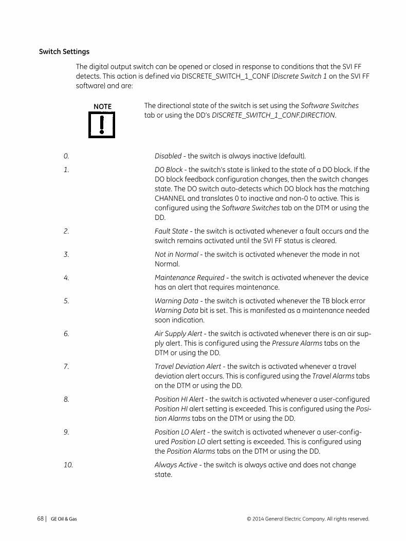
Switch Settings
The digital output switch can be opened or closed in response to conditions that the SVI FF detects. This action is defined via DISCRETE_SWITCH_1_CONF (Discrete Switch 1 on the SVI FF software) and are:
0. Disabled - the switch is always inactive (default).
1. DO Block - the switch’s state is linked to the state of a DO block. If the DO block feedback configuration changes, then the switch changes state. The DO switch auto-detects which DO block has the matching CHANNEL and translates 0 to inactive and non-0 to active. This is configured using the Software Switches tab on the DTM or using the DD.
2. Fault State - the switch is activated whenever a fault occurs and the switch remains activated until the SVI FF status is cleared.
3. Not in Normal - the switch is activated whenever the mode in not Normal.
4. Maintenance Required - the switch is activated whenever the device has an alert that requires maintenance.
5. Warning Data - the switch is activated whenever the TB block error Warning Data bit is set. This is manifested as a maintenance needed soon indication.
6. Air Supply Alert - the switch is activated whenever there is an air sup-ply alert. This is configured using the Pressure Alarms tabs on the DTM or using the DD.
7. Travel Deviation Alert - the switch is activated whenever a travel deviation alert occurs. This is configured using the Travel Alarms tabs on the DTM or using the DD.
8. Position HI Alert - the switch is activated whenever a user-configured Position HI alert setting is exceeded. This is configured using the Posi-tion Alarms tabs on the DTM or using the DD.
9. Position LO Alert - the switch is activated whenever a user-config-ured Position LO alert setting is exceeded. This is configured using the Position Alarms tabs on the DTM or using the DD.
10. Always Active - the switch is always active and does not change state.
The directional state of the switch is set using the Software Switches tab or using the DD’s DISCRETE_SWITCH_1_CONF.DIRECTION.
NOTE
© 2014 General Electric Company. All rights reserved.68 | =GE Oil & Gas

11. Always Inactive - the switch is always inactive.
12. Reset Occurred - the switch is active when a reset occurs and moves to configured default state.
13. Tight Cutoff - the switch is active when a tight cutoff is reached. At that time it closes if Normally Open and opens if Normally Closed. The switch resets once the threshold condition clears.
DISCRETE_SWITCH_2_CONF (Virtual Switch 2 on the SVI FF software), functions with the same settings. However, in this case, it drives a Virtual Discrete Switch (register) only. This register is usable to con-nect to the Discrete Input block.
The contact is OPEN when the SVI FF is unpowered and follows the user configuration after reboot.
NOTE
NOTE
Masoneilan SVI FF Instruction Manual =| 69© 2014 General Electric Company. All rights reserved.

This page intentionally left blank.

5. Check Out and Power Up
Overview
This section provides the checkout procedures required to determine if the SVI FF is in working order and to power up the unit.
Check Out Procedures
SVI FF checkout consists of physical and operational checkout procedures.
Physical Inspection
The physical checkout procedures include:
“Inspect Actuator, Linkages, or Rotary Adapter” on page 72
“Verify Mounting and Linkage Adjustment” on page 72
“Check the Magnet” on page 72
“Check the Electronic Module Connections” on page 75
Valve Mounting
Air Supply
Perform all procedures in this section before putting the SVI FF into operation.
NOTE
© 2014 General Electric Company. All rights reserved. Masoneilan SVI FF Instruction Manual =| 71

Inspect Actuator, Linkages, or Rotary Adapter
Verify that the mounting has not been damaged in shipment for a pre-mounted SVI FF, physically inspect the actuator, linkage. Record the following information for the configuration checkout:
1. Valve Air to Open (ATO) or Air to Close (ATC)
2. Actuator pressure rating
3. Actuator bench range
4. Inherent trim characteristic of the control valve; linear, equal percentage, or other.
Verify Mounting and Linkage Adjustment
Inspect the mounting and make any needed adjustments before running the positioner and checking the digital configuration.
Check the Magnet
There are two methods of checking the SVI FF magnet:
“Perform a Visual Inspection”
“Use ValVue to Check Magnet Position” on page 74
Perform a Visual Inspection
You must remove the positioner from the bracket to visually inspect the magnet orientation.
For rotary valves, such as a Camflex, or for actuators with rotation of less than 60°, the magnet assembly must be aligned as shown in Figure 35.
Figure 35 Magnet Orientation for Rotary Valves with Valve Closed
Refer to the valve data sheet or model number of control valve.NOTE
Magnet Axiswith ValveClosed
© 2014 General Electric Company. All rights reserved.72 | =GE Oil & Gas

For rotary valves, or for actuators with rotations greater than 60°, the magnet assembly must be aligned as shown in Figure 36.
Figure 36 Magnet Orientation for 90° Valve Rotation with De-energized Actuator
For reciprocating valves the adjustable link turnbuckle must be parallel to the valve stem. To ensure linearity in positioning verify that the hole in the lever aligns with the indicating hole in the bracket when the valve is in the closed position. Check that the bracket is mounted on the correct holes. (See Figure 37 for details).
Figure 37 Reciprocating Valve Mounting Bracket
For a reciprocating valve, it is not necessary to remove the positioner to visually inspect the magnet setting and linkage of a reciprocating valve.
MagnetAxiswith
Valve Closed
Increasing Signal = CCW Rotation
45°
NOTE
Masoneilan SVI FF Instruction Manual =| 73© 2014 General Electric Company. All rights reserved.

Use ValVue to Check Magnet Position
Use this procedure to check the magnet using ValVue:
1. Connect to the positioner in accordance with the ValVue instructions.
a. Run ValVue.
b. Select the installed positioner from the list of Connected Devices.
c. Select the: Check tab to view the current operating conditions of the selected positioner.
2. The Raw Position Value should be between – 1000 and +1000 when:
A reciprocating or less than 60° rotation rotary valve is closed.
A greater than 60° rotation rotary valve is at 45° of rotation (mid stroke for a 90° rotation rotary valve).
Check the Air Supply
1. Turn on the air supply.
2. Adjust the filter regulator.
3. Supply pressure must be a minimum of 5 (.35 bar, 34.5 kPa) to 10 psi (.69 bar, 68.97 kPa) greater than the spring range of the actuator but may not exceed the rated actuator pressure. Refer to the valve or actuator instruction manual.
4. Inspect the tubing connections between the filter-regulator and the positioner for leaks.
5. Verify that the tubing is not bent or crushed.
6. Verify that all fittings are leak tight.
Do not use Teflon pipe seal tape as it can shred into particles harmful to the pneumatic components.
CAUTION
© 2014 General Electric Company. All rights reserved.74 | =GE Oil & Gas
Check the Electronic Module Connections
The SVI FF terminal board has terminal blocks with screw connectors. Not all options are available for every model. Confirm the correctness of all applicable connections to the electronics module.
Operational Checkout
The operational checkout of the SVI FF consists of:
1. “Connect to the H1 Network”
2. “Power Up the SVI FF”
Connect to the H1 Network
Connect to the Fieldbus power supply, then check and configure with the local display and pushbuttons, if so equipped. Refer to “Pushbuttons and Local Display” on page 124 for further details.
If the SVI FF is not equipped with local display use ValVue and a PC with an FF setup or a handheld communicator.
Do not remove the instrument cover or connect to an electrical circuit in a Hazardous Area unless power is disconnected.
When an SVI FF is turned on, apply the air supply before applying the electrical input signal.
When an SVI FF is turned on, apply the air supply before applying the electrical power.
WARNING
NOTE
NOTE
Masoneilan SVI FF Instruction Manual =| 75© 2014 General Electric Company. All rights reserved.

Power Up the SVI FF
Before powering up the SVI FF:
1. Verify that the pneumatic connections and electronic cover screws are tightened. This is important to maintain the ingress protection level and the integrity of the flameproof enclosure.
2. If the installation is Intrinsically Safe, check that the proper barriers are installed and the field wiring meets local and national codes for an IS installation.
3. If the installation is non-incendive, then check that all the electrical connections are to approved devices and wiring meets local and national codes.
4. Verify that the markings on the label are consistent with the application.
5. Proceed to perform a Calibration and Configuration.
This process can cause the valve to move. Before proceeding be sure the valve is isolated from the process. Keep hands clear from moving parts.
When an SVI FF is turned on, apply the air supply before applying the electrical input signal.
Always power the SVI FF from a fieldbus power supply that supplies 9 to 32 VDC.
For Hazardous Location Installation information refer to “Specifications and References” on page 91..
If the SVI FF is specified without local pushbuttons and display, local operation is not available. Configure and calibrate with ValVue or using the DD a handheld Communicator.
WARNING
NOTE
CAUTION
NOTE
NOTE
© 2014 General Electric Company. All rights reserved.76 | =GE Oil & Gas

6. Failsafe/OOS Considerations
Failsafe Mode vs. OOS Mode
In the FF device certain hardware and firmware failures (Table 8) cause OOS mode. These failures are reported as a Failsafe condition on the Local User Interface. In most cases Failsafe indicates internal device damage.
To change the mode from OOS to any of the working modes, you must correct the Failsafe condition cause. Possibly the device electronics may need replacement, which involves contacting GE technical support.
Normally, the device Failsafe condition results in the OOS mode for the Transducer block. However, this behavior is configurable and may be changed using the parameter FAILED_STATE, sub-parameter PROPAGATE_APFS_TO_RB. By default this flag is set. If you set this flag, the following sequence occurs as a result of Failsafe:
1. The Transducer Block transitions to the OOS, which transitions the Resource block to OOS.
2. The Resource block then sets OOS for the downstream blocks.
If the faults in Table 8 occur several times in a row, ensure that environmental noise is not the cause. If the environment is not noisy contact GE’s Masoneilan.
CAUTION
© 2014 General Electric Company. All rights reserved. Masoneilan SVI FF Instruction Manual =| 77

Table 8 Failsafe Faults
Fault Name Description
POSITION_SENSOR If upon request temperature compensated remote position sensor reading is outside of range in degrees or internal position sensor reading is outside of range in degrees for five reads in a row. Indicates a slipping or blocked sensor.
TEMPERATURE_SENSOR
If, upon request, temperature compensated temperature sensor reading is outside of range in °C for five reads in a row. Indicates environment temperature is too hot/cold.
I2CBUS Internal serial bus fault . Indicates a hardware problem - may require replacing the positioner.
NVM_CHECKSUM0 If an FRAM record and its copy both have CRC errors (as detected by read on initialization,) OR if the temperature calibration table has not been written in its entirety (detected by CRC of column CRCs) OR bad FRAM signature. Indicates a hardware problem- may require replacing the positioner.
REF_VOLTAGE If temperature compensated reference voltage is out of range for five reads in a row, or if the raw reading is outside the range +-5% of nominal. Indicates a hardware problem- may require replacing the positioner.
PRESSURE4 If temperature compensated pressure sensor 4 (pilot) reading is outside of range. Indicates a hardware problem - may require replacing the positioner.
SELF_CHECK A valid hidden record (in RAM) existing upon reset indicating that a fatal event (watchdog, illegal interrupt, stack overflow, data checksum) occurred twice in a row. Indicates a hardware problem - may require replacing the positioner.
FSTATE_REQ Failed state requested by FF.
© 2014 General Electric Company. All rights reserved.78 | =GE Oil & Gas

7. Maintenance
SVI FF Maintenance and Repair
Repair
See “Spare Parts” on page 87 for kits available for permitted field repairs.
Tools Needed
5 mm hex key
3 mm hex key
Display Cover Removal and Installation
The display cover (shown in Figure 38) is provided as an option for the SVI FF. If you have an SVI FF with a solid cover and would like to replace the solid cover with a display cover follow the instructions below for removal and installation.
Do not remove the instrument cover or connect to an electrical circuit in a Hazardous Area unless the power is disconnected.
Only qualified service personnel are permitted to make repairs.
Only parts supplied by the factory are permitted. This includes not only the major assemblies but also mounting screws and O-rings. No substitutions with parts other than GE’s Masoneilan are permitted.
WARNING
NOTE
© 2014 General Electric Company. All rights reserved. Masoneilan SVI FF Instruction Manual =| 79

Removing the SVI FF Display Cover
To remove the SVI FF Display cover:
1. Using a 5 mm Hex key unscrew the four screws around the perimeter of the SVI FF cover.
2. Lift the cover off the positioner.
Figure 38 SVI FF Display and Pneumatic Covers
Installing the SVI FF Display Cover
The replacement display cover is shipped with a lanyard to prevent the cable (that connects from the display to the Terminal Board) from breaking. The lanyard must be inserted under the screw in the lower left corner, that attaches the terminal board to the SVI FF housing.
To Install the cover:
1. Install the lanyard and tighten the screw to 5 in-lbs (.565 N-m).
2. Using the 3mm hex key, remove the screw from the lower left corner, connecting the terminal board to the SVI FF housing.
3. Connect the cable from the display into the LCD connector on the terminal board.
4. Ensure that the gasket is in its groove in the housing.
5. Place the cover over the screw mounts.
After replacing the SVI FF Display Cover you must power up the unit (see “Power Up the SVI FF” on page 76 of this guide).
CoverDisplay
CoverPneumatic
NOTE
© 2014 General Electric Company. All rights reserved.80 | =GE Oil & Gas

6. Tighten the four screws with the 5 mm hex key.
7. After installing the new display power up the unit (refer to “Power Up the SVI FF” on page 76).
Make sure that:
The gasket is seated in the groove in the housing flange.
No wires or retaining cable can be trapped under the cover flange.
The flange area is not corroded and the surface is not scarred.
The four cover bolts are securely tightened to 50 in-lbs (5.65 N-m).
I⁄P Module Removal and Installation
Prior to removing the pneumatic components it is necessary to remove the electronics module cover (see “Removing the SVI FF Display Cover” on page 80) and the pneumatic cover first.
Do not remove the I/P module in a hazardous area unless the power is disconnected.
Application of more than 1.6 mA to the I/P motor can permanently damage it.
The I/P is rigidly assembled to a wire way sleeve that is a critical component for explosion proof service. Use care to slide the sleeve from the pneumatic module without applying a strain to it.
The cover of the SVI FF is a critical component for safety in Hazardous Areas. To ensure safe operation the flat surfaces of the cover and the housing must be clean and absolutely free of particles or dents. There must be no gap between the housing and cover; torque spec is 50 in-lbs (5.65 N-m).
CAUTION
Masoneilan SVI FF Instruction Manual =| 81© 2014 General Electric Company. All rights reserved.

Pneumatic Cover Removal: FF and High Flow
To remove the FF pneumatic cover:
1. Using a 3 mm hex key, remove the six screws from around the perimeter of the cover
2. Lift the cover off and put aside for re-installation.
To remove the FF High Flow pneumatic cover:
1. Using a 3 mm hex key, remove the four screws from around the perimeter of the cover (Figure 39 or Figure 40).
Figure 39 Pneumatic Cover Screws: High Flow
Figure 40 Pneumatic Cover Screws: FF (Four Shown)
2. Lift the cover off and put aside for installation.
Pneumatic Cover Removal
To remove the pneumatic cover:
1. Using a 3 mm hex key, remove the six screws from around the perimeter of the cover
2. Lift the cover off and put aside for re-installation.
© 2014 General Electric Company. All rights reserved.82 | =GE Oil & Gas

I/P Module Removal
To remove I⁄P module:
1. Disconnect the I/P wire from the terminal board.
2. Using a 3 mm hex key, remove the four screws from around the perimeter of the I⁄P module.
Figure 41 SVI FF High Flow Pneumatic Module with Single Acting Relay
3. Lift the module off the positioner.
I/P Module Installation
To install I⁄P module:
1. Place the module in the designated area on the positioner.
2. Using a 3 mm hex key, install the four screws around the perimeter of the I⁄P module.
3. Replace the I/P wire connector on the terminal board.
4. Replace the Display Cover (see “Installing the SVI FF Display Cover” on page 80).
Ensure that:
The wire is not damaged when feeding it through the housing.
A single O-ring is in place on the wire-sleeve and is not damaged.
The four retaining screws are tight and torque to 15 in-lb (1.7 N-m).
Inserting the wire sleeve through the housing does not require force.
Pneumatic Cover Installation
To install the pneumatic cover:
1. Place the cover over the pneumatic module.
2. Using a 3 mm hex key, install the six screws around the perimeter of the cover and torque to 8 in-lb (.9 N-m).
Masoneilan SVI FF Instruction Manual =| 83© 2014 General Electric Company. All rights reserved.

Relay Removal and Installation
To remove the pneumatic relay:
1. Using a 3 mm hex key, remove the three screws from around the perimeter of the relay.
2. Lift the relay off the positioner.
Relay Installation
To install pneumatic relay:
1. Place the relay in the designated area on the positioner.
2. Using a 3 mm hex key, install the three screws around the perimeter of the relay.
Make sure that:
1. The five O-rings are seated in the base of the relay and are not damaged.
2. The three mounting screws are tight and torque to 15 in-lb (1.7 N-m).
Adjusting I/P Zero
The I/P Zero is calibrated at the factory prior to shipment. If there is a problem with I/P zero please contact your representative.
Connecting Components to the Electronics Module
If it is necessary to remove and install any SVI FF component you may need to reconnect the component to the SVI FF Electronics Module via the SVI FF Terminal Board. Refer to “Wiring the SVI FF” on page 64 of this manual for instructions.
When you have completed maintenance on the pneumatic relay it is necessary to reinstall the pneumatic cover. Refer to on “Pneumatic Cover Installation” on page 83.
CAUTION
© 2014 General Electric Company. All rights reserved.84 | =GE Oil & Gas
Repair by Replacement
Using ValVue and repair-by-replacement is the fastest method to service an SVI FF. See the ValVue instruction manual for details regarding uploading and downloading configuration files. Upload all configuration information from the installed positioner to ValVue, then install the replacement positioner and download the configuration file into the replacement unit. Run STOPS, and Auto Tune, and the repair is complete. The positioner that was removed can be refurbished and reused.
Internal Diagnostics
The SVI FF performs internal self-diagnostics and hardware checks. When ValVue or handheld or the local display indicates that there are error messages write them down for troubleshooting.
FAILSAFE Mode
See “Failsafe/OOS Considerations” on page 77. for further discussions.
Several of the internal diagnostics tests puts the SVI FF into FAILSAFE mode if the errors continue for a preset time. When the SVI FF goes into FAILSAFE, the valve is driven to its Failsafe position. It remains in that position until a technician clears the cause of the error and resets the instrument. Reset is performed in two ways:
Connect a FF H1 segment and ValVue, and then change the Transducer block mode (if faults are already cleared).
or
Turn the power off and on.
To prevent the valve from moving after reset, put the controller in manual, and set the valve position setpoint to the failsafe position 0% if ATO, 100% if ATC.
Substitution of components can void safety approvals.NOTE
Masoneilan SVI FF Instruction Manual =| 85© 2014 General Electric Company. All rights reserved.

Upgrading Firmware
The SVI FF is equipped with a re-programmable Flash Memory for program storage. The firmware can be updated as improvements and advances are made in the embedded programs that operate the SVI FF. Updated firmware for the SVI FF can be obtained by contacting the factory.
Tools Required
Configured H1 segment
PC with Windows XP or later, 16 Mb RAM minimum
ValVue (provided with software upgrade on CD-ROM) or a handheld with the SVI FF DD.
Installing Firmware Upgrade
Upload and save the configuration prior to the installation procedure. Follow the ValVue instructions to save the old configuration. Follow the detailed instructions included with the update. The GE NI-FBUS help contains information for H1 firmware download.
When maintenance is complete perform the checkout procedure detailed in “Check Out Procedures” on page 71.
© 2014 General Electric Company. All rights reserved.86 | =GE Oil & Gas

Spare Parts
Electronics:
SVI FF-2 (720024064-999-0000)SVI FF-3 (720024066-999-0000)SVI FF-2 Double Acting (720024067-999-0000)SVI FF-3 Double Acting (720024068-999-0000)
SA Reinforced Pneumatic Cover Kit (720028475-999-0000)
DA Reinforced Pneumatic Cover Kit (720028476-999-0000)
SA IP Assembly Reinforced Cover (720028473-999-0000)
Item Description Quantity1 ELECTRONIC ASSEMBLY SVI II AP 12 SILICONE GASKET, COVER ELECTRONICS 1
3 SCR HEX SHCS M4 X 0.7 X 27 MICROSPHERES 593 PATCH 6
4 O-RING, REF NO. 2-006 65 INSTRUCTIONS 1
Item No.
Description Quantity
1 SCR HEX SHCS M4 X 0.7 X 25 MICROSPHERES 593 PATCH 6
2 GASKET MANIFOLD S/A 13 REINFORCED PNEUMATICS COVER SA 1
Item No.
Description Quantity
1 SCR HEX SHCS M4 X 0.7 X 25 MICROSPHERES 593 PATCH 4
2 GASKET I/P COVER D/A SVI2AP 13 REINFORCED COVER PNEUMATICS DA 1
Item No.
Description Quantity
1 I/P, ASSY 12 O-RING, I/P STEM 2
3 SCR HEX SHCS M4 X 0.7 X 60 MICROSPHERES 593 PATCH 4
4 REINFORCED PNEUMATICS COVER 15 PNEUMATICS COVER GASKET 1
6 SCR HEX SHCS M4 X 0.7 X 25 MICROSPHERES 593 PATCH 6
7 INSTRUCTIONS 1
Masoneilan SVI FF Instruction Manual =| 87© 2014 General Electric Company. All rights reserved.

DA IP Assembly Reinforced Cover (720028474-999-0000)
Standard Push Button Display Silicone Gasket (720028469-999-0000)
Offshore Push Button Display Silicone Gasket (720028471-999-0000)
Item No.
Description Quantity
1 IP ASSEMBLY, SVI II ESD 12 O-RING, I/P STEM 2
3 SCR HEX SHCS M4 X 0.7 X 60 MICROSPHERES 593 PATCH 4
4 REINFORCED PNEUMATICS COVER 15 PNEUMATICS COVER GASKET 1
6 SCR HEX SHCS M4 X 0.7 X 25 MICROSPHERES 593 PATCH 4
7 INSTRUCTIONS 1
Item No.
Description Quantity
1 ASSY, COVER WINDOW 12 Silicone Gasket, Cover, Electronics 13 Instructions 1
Item No.
Description Quantity
1 ASSY COVER WINDOW, MARINE 12 Silicone Gasket, Cover, Electronics 13 Instructions 1
© 2014 General Electric Company. All rights reserved.88 | =GE Oil & Gas

SA Standard and Offshore Relay Reinforce Cover (720028472-999-0000)
DA Standard Relay (720003881-999-0000)
DA Offshore Relay (720003882-999-0000)
Pushbutton Door, Kit (720002448-999-0000)
HC SA Standard Relay (720014541-999-0000)
Item No.
Description Quantity
1 RELAY, SA 1
2 SCR HEX SHCS M4 X 0.7 X 60 MICROSPHERES 593 PATCH 3
3 REINFORCED PNEUMATICS COVER 14 PNEUMATICS COVER GASKET 1
5 SCR HEX SHCS M4 X 0.7 X 25 MICROSPHERES 593 PATCH 6
6 INSTRUCTIONS 1
Item No.
Description Quantity
1 RELAY, DA Standard 12:1 12 SCR HEX SHCS M4 X 0.7 X 60 MICROSPHERES 593 PATCH 43 O-RING, CONTOURED, DA 12:1 RELAY 14 INSTRUCTIONS 1
Item No.
Description Quantity
1 RELAY, DA Offshore 12:1 12 SCR HEX SHCS M4 X 0.7 X 60 MICROSPHERES 593 PATCH 43 O-RING, CONTOURED, DA 12:1 RELAY 14 INSTRUCTIONS 1
Item No.
Description Quantity
1 SCREW CAPTIVE PANEL 12 PIVOT PIN PUSH BUTTON COVER SVI II 13 CIRCLIP SHAFT PUSH B 34 COVER PUSHBUTTON SVI2AP 15 GASKET COVER PUSHBUTTON SVI2 1
Item No.
Description Quantity
1 Relay SA HC 12 M4 X 0.7 X 60 SHCS 53 O-RING ID 9.19 [0.362] WIDTH 2.62 [0.103] REF NO 2-110 34 O-RING ID 29.87 [1.176] WIDTH 1.78 [0.0703] REF NO 2-025 1
5 O-RING ID 9.137.82 [1.498] WIDTH 1.78 [0.0703] REF NO 2-1029 1
6 INSTRUCTIONS 1
Masoneilan SVI FF Instruction Manual =| 89© 2014 General Electric Company. All rights reserved.

This page intentionally left blank.
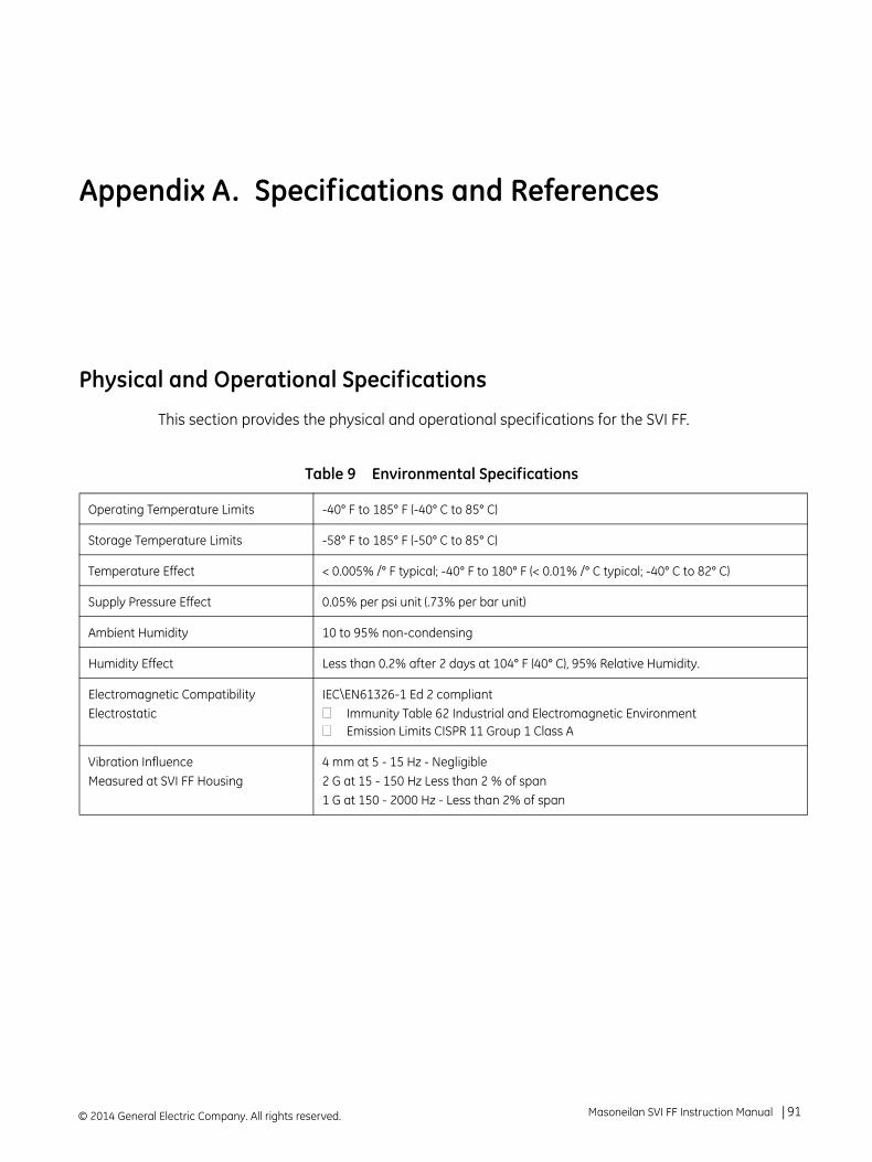
Appendix A. Specifications and References
Physical and Operational Specifications
This section provides the physical and operational specifications for the SVI FF.
Table 9 Environmental Specifications
Operating Temperature Limits -40° F to 185° F (-40° C to 85° C)
Storage Temperature Limits -58° F to 185° F (-50° C to 85° C)
Temperature Effect < 0.005% /° F typical; -40° F to 180° F (< 0.01% /° C typical; -40° C to 82° C)
Supply Pressure Effect 0.05% per psi unit (.73% per bar unit)
Ambient Humidity 10 to 95% non-condensing
Humidity Effect Less than 0.2% after 2 days at 104° F (40° C), 95% Relative Humidity.
Electromagnetic Compatibility Electrostatic
IEC\EN61326-1 Ed 2 compliantImmunity Table 62 Industrial and Electromagnetic EnvironmentEmission Limits CISPR 11 Group 1 Class A
Vibration InfluenceMeasured at SVI FF Housing
4 mm at 5 - 15 Hz - Negligible2 G at 15 - 150 Hz Less than 2 % of span1 G at 150 - 2000 Hz - Less than 2% of span
© 2014 General Electric Company. All rights reserved. Masoneilan SVI FF Instruction Manual =| 91

* Specifications are subject to change without notice
Table 10 Operational Specifications*
Accuracy +/- 0.5% (typical +/-0. 10% or less) Full Span
Hysteresis and Deadband +/- 0.3% Full Span
Repeatability +/- 0.3% Full Span
Conformity/Linearity +/- 0.5% Full Span
Start-Up Drift Less than 0.02% in first hour
Long Term Drift Less than 0.003% per month
Position Travel Limits Rotary: 18 - 140° Reciprocating: 0.25” - 4“(6 mm - 100 mm); Extended mounting: > 4" (100 mm) Note: Above 4” (100 mm) consult factory for mounting instruc-tions.
Flow CharacteristicsApplied in addition to the control valve’s inherent characteristic.
Linear Equal Percentage (of 50:1 or 30:1) CamflexQuick Opening (inverse of 50:1 equal percentage)User ConfigurableTight Shut Off (0 -20% of input)
Position Auto TuneSVI FF performs automatic determination of the opti-mal valve position control parameters. In addition to P, I, D, the position algorithm uses damping, symmetry for exhaust and fill time constants, dead zone and magnitude characterization parameters. Auto Tune is optimized for 5% step changes with negligible over-shoot. After the Auto Tune process is completed, you can further adjust the positioner tuning parameters to more conservative or to more responsive values.
Proportional gain: 0 to 5, displayed as 0 to 5000Integral time: 0 to 100 seconds - displayed as 0 to 1000 (1/10s)Derivative time: 0 to 200 millisecondsDead Zone: 0 to +/-5% (0 to 10% deadband)Padj: +/- 3000 (depends on P)Beta (non-linear gain factor): -9 to +9Stroking Time: 0 to 250 secondsPosition compensation coefficient: 1 to 20Boost: 0 to 20
© 2014 General Electric Company. All rights reserved.92 | =GE Oil & Gas

Table 11 Input Signal, Power, and Display Specifications
Input voltage 9 - 32 V polarity independent
Normal/Maximum current 17.4/ 18.3 mA
Wire Size FF input: 12 to 22 AWGAll others: 14 to 26 AWG
Digital Communication Protocol FOUNDATION Fieldbus registered device
Physical Layer Type (s) 121 - Low-power signaling, bus powered, Entity Model I.S.511 - Low-power signaling, bus powered, FISCO I.S.
Local Display (optional) LCD, explosion proof
Push Buttons External, Three Explosion Proof / Flameproof push buttons
Table 12 Construction Material Specifications
Housing and Cover Aluminum ASTM 360 standard316L optional
Weight Standard Flow Model:Aluminum - 7.4 lbs./ 3.3 kgStainless Steel - 16 lbs/ 7.3 kg
High Flow Model:With Display: 9.4 lbs./ 4.2 kgWithout Display: 8.9 lbs./ 4.0 kg
Relay and Manifold Standard Flow Model: Single Acting - PPS, 300 Series Stainless Steel, nitrile diaphragmsDouble Acting - 300 Series Stainless Steel, Ryton Aluminum 6061 T6, Ryton
High Flow Model: 300 Series Stainless Steel, Ryton
Aluminum 6061 T6, Ryton
I/P Motor 430 stainless steel, PPS, 300 series stainless steel
Mounting Bracket 300 series stainless steel
Magnet Holder Corrosion Protected Anodized Aluminum 6061 T6
Pole Ring 416 stainless steel
Levers 300 Series stainless steel
Masoneilan SVI FF Instruction Manual =| 93© 2014 General Electric Company. All rights reserved.

Table 13 System Connectivity
DD Registered with FOUNDATION Field-bus Foundation
Yes, available through foundation website
Diagnostics Options include: Valve signature, ramp, friction, stroking speed, step response, cumulative travel, cumulative cycles, and time of operation in near-closed position. Some diagnostics require pressure sensor and ValVue software.
Table 14 Pneumatics Single Acting Standard Flow
Air Supply Dry, oil-free, 5 micron filtered and regulated air and sweet natural gas(See ISA S7.3)
Action Direct Acting
Supply Pressure 20 -150 psi max. (1.4 - 10.3 bar)
Regulate 5 - 10 psi (.345 bar - .69 bar) above actuator spring range. Do not exceed actuator rating.
Air Delivery - Single Acting Relay 10.0 scfm (280 l/m) at 30 psi (2.1 bar) supply16.6 scfm (470 l/m) at 60 psi (4.2 bar) supply23.3 scfm (660 l/m) at 90 psi (6.3 bar) supply
Air Capacity(flow coefficient)
Loading CV = 0.57Venting CV = 0.53
Air Consumption 0.20 scfm (5.7 sl/m) at 30 psi (2.1 bar) supply0.28 scfm (8 sl/m) at 60 psi (4.2 bar) supply0.42 scfm (12 sl/m) at 90 psi (6.3 bar) supply
Air Supply Failure Single Acting Relay
On supply failure the actuator output drops. Some overshoot may occur when air pressure returns after a period without air supply pressure. Always set control set point to 0%, and put the process control system in manual, for smooth recovery from air supply failure.
Loss of Input Signal Output drops to low pressure.
Output Pressure 0 - 150 psi (10.3 bar) max
© 2014 General Electric Company. All rights reserved.94 | =GE Oil & Gas

Table 15 High Flow Pneumatics Single Acting High Flow
Air Supply Dry, oil-free, 5 micron filtered, filtered and regulated air and sweet natural gas (See ISA S7.3)
Action Direct Acting
Supply Pressure 20 -150 psi max. (1.4 - 10.3 bar)
Regulate 5 - 10 psi (.345 bar - .69 bar) above actuator spring range. Do not exceed actuator rating.
Air Delivery - Single Acting Relay 39.0 scfm (1104 l/m) at 30 psi (2.1 bar) supply70.6 scfm (2000 l/m) at 60 psi (4.2 bar) supply102.0 scfm (2888 l/m) at 90 psi (6.3 bar) supply134.0 scfm (3794 l/m) at 120 psi (8.4 bar) supply
Air Capacity(flow coefficient)
Loading CV = 2.2Venting CV = 2.2
Air Consumption 0.20 scfm (5.8 sl/m) at 30 psi (2.1 bar) supply0.45 scfm (12.6 sl/m) at 60 psi (4.2 bar) supply0.65 scfm (18.3 sl/m) at 90 psi (6.3 bar) supply0.84 scfm (23.9 sl/m) at 120 psi (8.4 bar) supply
Air Supply Failure Single Acting Relay
On supply failure the actuator output drops. Some overshoot may occur when air pressure returns after a period without air supply pressure. Always set control set point to 0%, and put the process control system in manual, for smooth recovery from air supply failure.
Loss of Input Signal Output drops to low pressure.
Output Pressure 0-150 psi (10.3 bar) max
Masoneilan SVI FF Instruction Manual =| 95© 2014 General Electric Company. All rights reserved.
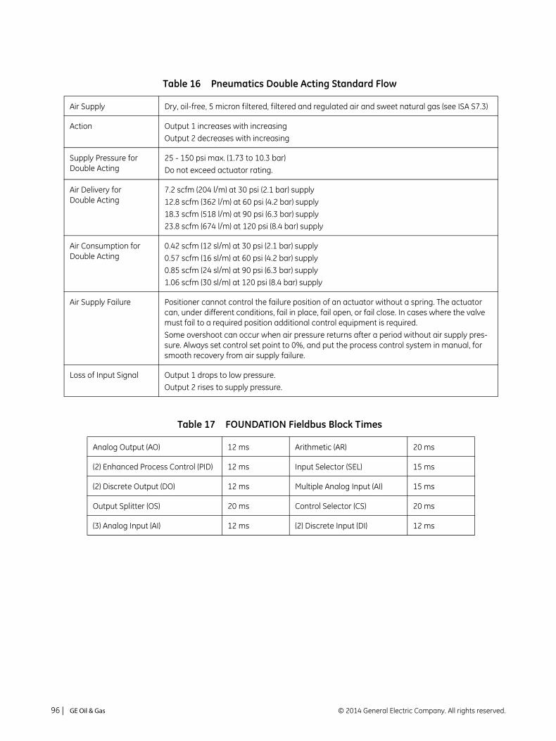
Table 16 Pneumatics Double Acting Standard Flow
Air Supply Dry, oil-free, 5 micron filtered, filtered and regulated air and sweet natural gas (see ISA S7.3)
Action Output 1 increases with increasingOutput 2 decreases with increasing
Supply Pressure for Double Acting
25 - 150 psi max. (1.73 to 10.3 bar)Do not exceed actuator rating.
Air Delivery for Double Acting
7.2 scfm (204 l/m) at 30 psi (2.1 bar) supply12.8 scfm (362 l/m) at 60 psi (4.2 bar) supply18.3 scfm (518 l/m) at 90 psi (6.3 bar) supply23.8 scfm (674 l/m) at 120 psi (8.4 bar) supply
Air Consumption for Double Acting
0.42 scfm (12 sl/m) at 30 psi (2.1 bar) supply0.57 scfm (16 sl/m) at 60 psi (4.2 bar) supply0.85 scfm (24 sl/m) at 90 psi (6.3 bar) supply1.06 scfm (30 sl/m) at 120 psi (8.4 bar) supply
Air Supply Failure Positioner cannot control the failure position of an actuator without a spring. The actuator can, under different conditions, fail in place, fail open, or fail close. In cases where the valve must fail to a required position additional control equipment is required.Some overshoot can occur when air pressure returns after a period without air supply pres-sure. Always set control set point to 0%, and put the process control system in manual, for smooth recovery from air supply failure.
Loss of Input Signal Output 1 drops to low pressure.Output 2 rises to supply pressure.
Table 17 FOUNDATION Fieldbus Block Times
Analog Output (AO) 12 ms Arithmetic (AR) 20 ms
(2) Enhanced Process Control (PID) 12 ms Input Selector (SEL) 15 ms
(2) Discrete Output (DO) 12 ms Multiple Analog Input (AI) 15 ms
Output Splitter (OS) 20 ms Control Selector (CS) 20 ms
(3) Analog Input (AI) 12 ms (2) Discrete Input (DI) 12 ms
© 2014 General Electric Company. All rights reserved.96 | =GE Oil & Gas
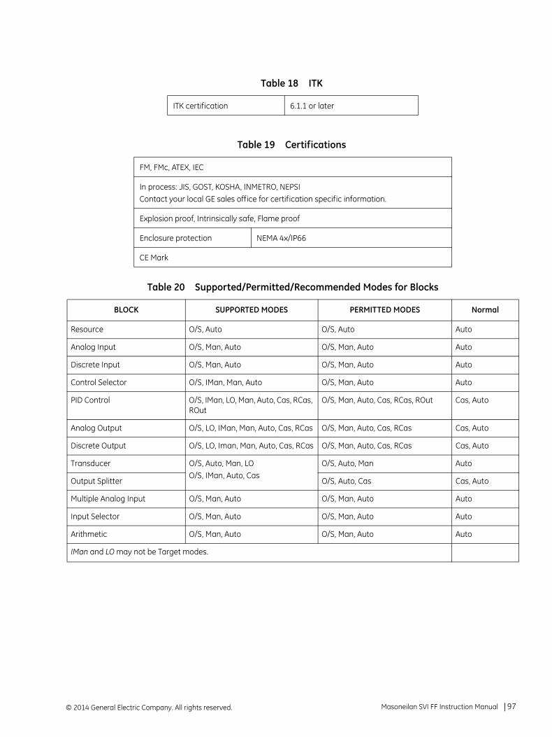
Table 18 ITK
ITK certification 6.1.1 or later
Table 19 Certifications
FM, FMc, ATEX, IEC
In process: JIS, GOST, KOSHA, INMETRO, NEPSIContact your local GE sales office for certification specific information.
Explosion proof, Intrinsically safe, Flame proof
Enclosure protection NEMA 4x/IP66
CE Mark
Table 20 Supported/Permitted/Recommended Modes for Blocks
BLOCK SUPPORTED MODES PERMITTED MODES Normal
Resource O/S, Auto O/S, Auto Auto
Analog Input O/S, Man, Auto O/S, Man, Auto Auto
Discrete Input O/S, Man, Auto O/S, Man, Auto Auto
Control Selector O/S, IMan, Man, Auto O/S, Man, Auto Auto
PID Control O/S, IMan, LO, Man, Auto, Cas, RCas, ROut
O/S, Man, Auto, Cas, RCas, ROut Cas, Auto
Analog Output O/S, LO, IMan, Man, Auto, Cas, RCas O/S, Man, Auto, Cas, RCas Cas, Auto
Discrete Output O/S, LO, Iman, Man, Auto, Cas, RCas O/S, Man, Auto, Cas, RCas Cas, Auto
Transducer O/S, Auto, Man, LOO/S, IMan, Auto, Cas
O/S, Auto, Man Auto
Output Splitter O/S, Auto, Cas Cas, Auto
Multiple Analog Input O/S, Man, Auto O/S, Man, Auto Auto
Input Selector O/S, Man, Auto O/S, Man, Auto Auto
Arithmetic O/S, Man, Auto O/S, Man, Auto Auto
IMan and LO may not be Target modes.
Masoneilan SVI FF Instruction Manual =| 97© 2014 General Electric Company. All rights reserved.

Figure 42 SVI FF Model Numbering
Series Identification SVI FF -abcdefgh
a Style 2, 32. SD Version - Standard Diagnostics3. AD Version - Advanced Diagnostics
b Pneumatic Train 1, 21. Single Acting2. Double Acting
c Pneumatics1. Standard flow
d Display 1,2,3,41. No Display or Pushbuttons2. With Display and Pushbuttons3. No Display or Pushbuttons, Marine4. With Display and Pushbuttons, Marine
e Communications F. FF
f Options1. None
g Agency Approvals 2. Unilabeled (ATEX, IEC, FMc, FM)
h Other Agencies1. North American Zones
Approved Configuration Codes
SVI FF- 23
12
12
1234
F 1 2 1
2. High Flow
23456
2. GOST*3. KOSHA*4. NEPSI*5. INMETRO*6. JIS*
* Pending at time of publication7. CCOE*
7
© 2014 General Electric Company. All rights reserved.98 | =GE Oil & Gas

Appendix B. About Fieldbus
Outline
Fieldbus is a bi-directional digital communication protocol for field devices, which offers an advancement in technologies for process control systems and is widely employed by numerous field devices.
SVI FF employs the specification standardized by The Fieldbus Foundation, and provides interoperability between GE’s Masoneilan devices and those produced by other manufacturers.
Fieldbus comes with software consisting of AO function block, two DI function blocks and optional PID function block and a selection of other blocks as necessary, providing the means to implement a flexible instrumentation system.
For more general information on other features, engineering, design, construction work, startup and maintenance of Fieldbus, refer to Fieldbus Technical Information (TI 38K3A01-01E).
Internal Structure of SVI FF
The SVI FF contains two virtual field devices (VFD) with the following functions.
System/Network Management VFD
Sets node addresses and Physical Device tags (PD Tag) necessary for communication.
Controls the scheduling and execution of function blocks.
Manages block parameters, block-to-block signal propagation and communication resources (Virtual Communication Relationship: VCR).
Function Block VFD
Resource block - Manages the information common to each FB VFD in SVI FF.
Transducer block - Operates as the intermediary between Hardware I/O (actuator, sensor) and AO/DI function blocks; passes the control signal from AO function block to I/P module to control the valve position.
© 2014 General Electric Company. All rights reserved. Masoneilan SVI FF Instruction Manual =| 99

AO block - Accepts a:
Control signal from an upstream block and pass the signal to Transducer block.
Valve position signal from Transducer block and feedbacks it to an upstream block.
DI block - Receives the discrete signal from Transducer block and outputs them.
PID block - Offers PID control function. This is configured by choosing the algorithm:
Ideal algorithm
Parallel algorithm
Series algorithm
I-PD algorithm
IP-D algorithm
DO block - Takes a binary setpoint and writes it to a specified I/O channel to produce an output signal. The Discrete Output function block supports mode control, output tracking, and simulation.
AR (Arithmetic) block - Contains math functions that are selected by name.
IS block - Provides selection of up to four inputs and generates an output based on the configured action. This block normally receives its inputs from AI blocks. The block performs maximum, minimum, middle, average and first good signal selection.
OS (Output Splitter) block - Splits a single control signal into two parts for coordinating the actions of two or more valves, such as for split-range control or sequencing control of a large and a small valve.
AI block - The analog input (AI) block is designed to let users use standard models of the generalized signal conditioning function. The AI block receives and processes data measured by the transducer block as follows:
Scaling
Square-root calculation (for an orifice plate)
Low-pass filter
Alarm generation
© 2014 General Electric Company. All rights reserved.100 | =GE Oil & Gas

Logical Structure of Each Block
Setting of various parameters, node addresses, and PD Tags shown in Figure 43 is required before starting operation.
Figure 43 Logical Structure of Each Block
Function Block VFD
PD tag (Device tag)
Node address
CommunicationParameters
VCR
Function blockexecution schedule
System/network management VFD
PID Function
DI Functions
AO Functionblock
Block tag
Parameters
OUT
Resource block
Block tag
Parameters
Output to other blocks
Input from other blocks
Position feedback signal
Control output
Position Sensor
I/P M
odule
Block tag
Parameters
Transducer block
Masoneilan SVI FF Instruction Manual =| 101© 2014 General Electric Company. All rights reserved.

System Configuration
The following instruments are required for use with Fieldbus devices:
Power supply Fieldbus requires a dedicated power supply. It is recommended that current capacity be well over the total value of the maximum current consumed by all devices (including the host). Conventional DC cur-rent cannot be used as is.
Terminators Fieldbus requires two terminators. Refer to the supplier for details of terminators that are attached to the host.
Field devices Connect the field devices necessary for instrumentation.
SVI FF has passed the interoperability test conducted by The Fieldbus Foundation. In order to properly start Fieldbus, use the devices to satisfy the requirements of the above test.
Host Used for accessing field devices. A dedicated host (such as DCS) is used for an instrumentation line while dedicated communication tools are used for experimental purposes.
Cable Used for connecting devices. Refer to Fieldbus Technical Information (TI 38K3A01-01E) for details of instrumentation cabling. Provide a cable sufficiently long to connect all devices. For field branch cabling, use terminal boards or a connection box, as required. If the total length of the cable is in a range of two to three meters for labo-ratory or other experimental use, use a twisted pair wire with a cross section of 0.9 mm2 or more (AWG #18) and cycle period of within 5 cm (2").
Termination processing depends on the type of device being deployed. For SVI FF, use an M4 screw terminal claw. Some hosts require a connector.
Refer to GE’s Masoneilan when making arrangements to purchase the recommended equipment.
The number of devices that can be connected to a single bus and the cable length vary depending on system design.
When constructing systems, both the basic and overall design must be carefully considered to allow device performance to be fully exploited.
© 2014 General Electric Company. All rights reserved.102 | =GE Oil & Gas

Connection of Devices
Connect the devices as shown in Figure 44. Connect the terminators at both ends of the trunk, with a minimum length of the spur laid for connection.
Figure 44 Cabling
Before using a Fieldbus configuration tool other than the existing host, confirm it does not affect the loop functionality in which all devices are already installed. Disconnect the relevant control loop from the bus if necessary.
Integration of DD
If the host supports DD (Device Description), install the DD of the SVI FF. Check if the host has the following directory under its default DD directory: 004745/0008.
If this directory is not found, the DD of SVI FF has not been included:
1. Create the above directory.
2. Copy the DD file into the directory. The name and attribute of all parameters of the SVI FF appear.There are two versions of the DD file:
Version 5 (recommended): The files names are: (0m0n.ff5,0m0n.sy5) (m, n is a numeral).
Version 4: The files names are: (0m0n.ff0,0m0n.sym) (m, n is a numeral).
Off-line configuration is done using the capability file (CFF). If you do not have the DD or capability file for the SVI FF, download it from http://www.ge-mcs.com/en/download.html or from the Foundation Fieldbus Foundation website.
Fieldbus power supply SVI FF HOST
Terminator
Terminator
Masoneilan SVI FF Instruction Manual =| 103© 2014 General Electric Company. All rights reserved.

This page intentionally left blank.

Appendix C. Foundation Fieldbus: Process Example
Overview
This section introduces a process example and several concepts used throughout various discussions. It briefly introduces Foundation Fieldbus blocks and some of the essential block concepts. The process example is a heat exchanger (Figure 45) with two control valves and three measurement devices. The controls are configured in a cascade arrangement to illustrate concepts of transfer between modes and states of the various levels of control.
Figure 45 Heat Exchanger
Vapor
Cooling water
© 2014 General Electric Company. All rights reserved. Masoneilan SVI FF Instruction Manual =| 105

Reference Model Process
The Heat Exchanger model, shown in Figure 45, is not a practical example but it does incorporate elements that illustrate important SVI FF features. Each module has a device tag used for SVI FF identification. The process consists of a vessel with a product vapor inflow that is condensed and flows out as a liquid outflow. The tank level is controlled by an outflow control valve, LV 201. The tank contents are chilled by coolant water. The temperature is controlled by a temperature controller cascaded to a flow controller. The coolant flow is controlled by control valve FV 101.
P & I D
Figure 46 shows, in schematic form, the physical devices and indicates the measurement and control functions that reside in each device. The flow of control information between devices is indicated by dashed lines.
The coolant flow control valve, FV 101, has a PID control function block, one DI block and an Analog Output block (AO), all located within the valve positioner. The DI block can set either a high limit, a low limit or both the high and low limits.
The coolant flow transmitter, FT 102, has only a transmitter function. It has Analog Input function block (AI) implemented in its firmware.
The temperature transmitter TT 103 contains one Analog Input block and a PID block.
The PID blocks in TT 103 and FV 101 devices are scheduled to work in cascade as shown in Figure 47. The AO block in the FV 101 receives the output from the FV 101 PID block and via the transducer block transmits it to the control hardware of the valve.
The condensed fluid flow control valve, FV 201, has a DI block and an Analog Output block, all located within the valve positioner. Liquid level is controlled by a remote controller LC201 to demonstrate Remote Cascade operation.
The level transmitter LT 202 includes an Analog Input block. The flow controller in LV 201 receives the process measurement from level transmitter LT 202. The PID control regulates the valve LV201.
The DI block ZSL 101, depending on the wiring, serves as low and/or high stem position limit switches in the control valve positioner FV 101. The DI block ZSL 201, depending on the wiring, serves as low and/or high stem position limit switches in the control valve positioner FV 201.
© 2014 General Electric Company. All rights reserved.106 | =GE Oil & Gas

Figure 46 Piping and Instrumentation Diagram
Function Block Links
Each of the control functions is represented in the control configuration as Foundation Fieldbus function blocks. They are grouped according to the physical device containing them and they are shown with the links between the blocks, soft wiring, for data flow.
All the blocks in the temperature cascade are shown in Figure 47. Similarly The level loop function blocks are shown in Figure 48.
Figure 47 Temperature Cascade Block Diagram
Masoneilan SVI FF Instruction Manual =| 107© 2014 General Electric Company. All rights reserved.
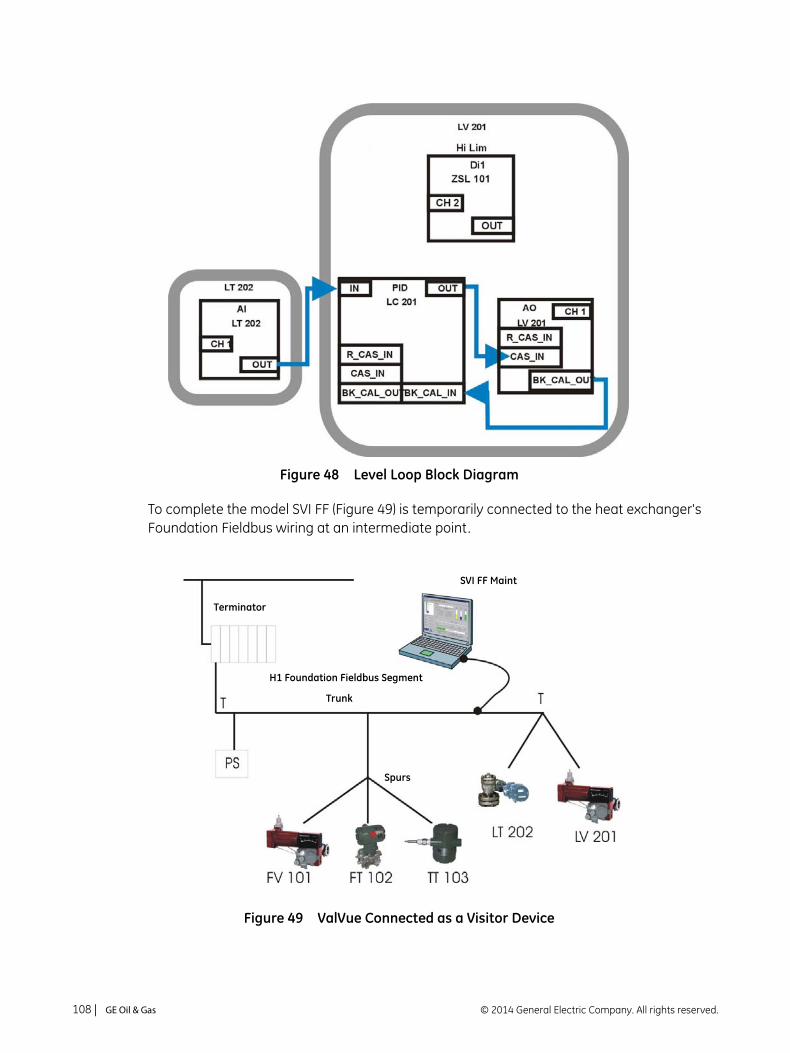
Figure 48 Level Loop Block Diagram
To complete the model SVI FF (Figure 49) is temporarily connected to the heat exchanger's Foundation Fieldbus wiring at an intermediate point.
Figure 49 ValVue Connected as a Visitor Device
Terminator
H1 Foundation Fieldbus Segment
Trunk
SVI FF Maint
Spurs
© 2014 General Electric Company. All rights reserved.108 | =GE Oil & Gas

The Heat Exchanger Reference Model segment consists of a Heat Exchanger Host in a control center with a Foundation Fieldbus trunk connected to two junction boxes. One junction box has spurs to the flow and temperature control devices and the other connects to the devices controlling tank level. A power supply with isolation electronics and two terminators completes the configuration. Configure the ValVue maintenance computer interface cards (NIFBUS) so as to not interfere with the Heat Exchanger Host.
Device Operational States and Block Modes
SVI FF manages the operational states of the positioner and its embedded PID controller by controlling the target modes for each of the function blocks. The actual mode of each block can be different from the target mode. The actual mode is controlled by the block itself in accordance with mode rules based on the quality of the data and modes of the linked blocks. A brief summary of modes follows, a thorough discussion of modes is beyond the scope of this instruction manual. You can refer to the Fieldbus Foundation specification that specifies the formal rules for mode changing.
Three operational states are set by SVI FF. Out Of Service (OOS) forces all of the blocks to Out Of Service mode. The outputs remain at the values prior to the state change, but their status indicates that the block is OOS. All output calculation is suspended. Back calculation values are passed to other linked blocks to enable initialization. The PID block remains in OOS after configuration changes unless it is put into one of its allowed modes from the PID dialog box.
Block Modes
All blocks (function/transducer/resource) have operating modes. There are eight modes defined in the Foundation Fieldbus specification. Not all modes are supported by every block. For example, the Discrete Input Block (DI) supports Auto, Man and OOS. The action of the modes are described in the following paragraphs. Transfers between modes are managed by the function blocks in response to manual commands that in turn responded to changes in the modes of linked blocks and responded to changes in the quality of the parameters that are transmitted. Control and status options can be set to manage mode changing behavior.
BLOCK_ERR_DESC_1 often can provide information as to why the block is not switched to the TARGET mode.
Never connect a PC to an operating segment unless it is configured as a Basic Device. See Figure 46 to view the configuration options.
Do not cause a short circuit in a working segment while connecting or disconnecting any device.
CAUTION
Masoneilan SVI FF Instruction Manual =| 109© 2014 General Electric Company. All rights reserved.

Remote-Output (Rout) The block output is set by a control application running on an inter-face device through the remote-output-in parameter. The algorithm is bypassed and the remote block controls its output directly. The algorithm must initialize so that no bump is experienced when the mode switches to Auto. A remote-output-out parameter is main-tained by the block to support initialization of the control application when the block mode is not remote- output. The setpoint can be maintained or initialized to the process variable value.
Remote-Cascade (RCas) The block setpoint is set by a control application running on an inter-face device through the remote-cascade in parameter. Based on this setpoint the normal block algorithm determines the primary output value. A remote-cascade out parameter is maintained by the block to support initialization of the control application when the block mode is not remote-cascade.
Cascade (Cas) A setpoint value, scheduled and published by another function block through the Cascade input parameter, is used by the normal block algorithm in determining the primary output value. This connection between function blocks is defined by a link object.
Automatic (Auto) A local setpoint value is used by the normal block algorithm in deter-mining the primary output value. The local setpoint value can be written to by an operator through an interface device.
Manual (Man) The block output is not being calculated, although it can be limited. It is directly set by the operator through an FF H1 interface device. The algorithm must initialize so that no bump is experienced when the mode switches. The setpoint can be maintained or initialized to the process variable parameter value or to the setpoint value associated with the previous retained target mode.
Local Override (LO) Applies to control and output blocks that support a track input parameter. In the local override mode the block output is being set to track the value of the track input parameter. The algorithm must ini-tialize so that no bump is experienced when the mode switches from LO back to the target mode. The setpoint can be maintained or ini-tialized to the process variable parameter value.
The SVI FF Transducer block is in this mode when the device is in setup mode from the local display.
The block is switched to TARGET mode when the local display is switched to Normal.
© 2014 General Electric Company. All rights reserved.110 | =GE Oil & Gas

Initialization Manual (IMan) The block output is set in response to the back-calculation input parameter status. When the status indicates there is no path to the final output element, the control blocks must initialize to provide for bumpless transfer when the condition clears. A back-calculation out parameter is supported by all output and control class function blocks. The setpoint can be maintained or initialized to the process variable parameter value.
Out of Service (OOS) The block is not being evaluated. The output and setpoint are main-tained at last value.
When the Transducer block is in OOS mode the output to the valve is de-energized.
Multiple Modes and States
The Analog Output Block (AO) must go to CAS mode to connect to a PID function block in cascade. To prevent the setpoint signal out of the Analog Output Block (AO) from setting the valve position into the transducer block, the Analog Output Block (AO) must go into OOS mode. Table 21 shows several examples of mode operation.
When a block is in OOS mode its output status is bad. Any connected blocks know and automatically change their modes. For example, when a PID block sees bad status in BKCAL IN it goes to IMAN mode for initialization to the downstream block while awaiting the status to return to good cascade.
Examples of Operational States
Examples of operational states that are combinations of block modes are shown in this section. A new device or a newly configured device can start up in the out of service (OOS) state (Table 21).
Ensure before switching back that a safe operating environment exists.CAUTION
Table 21 Mode Operation
Operation (AI) PID AO TB
Configure the transducer block (Auto tuning, travel calibration, etc.)
MAN
Configure transducer block (Chang-ing position control parameters, etc.)
OOS
Masoneilan SVI FF Instruction Manual =| 111© 2014 General Electric Company. All rights reserved.

Transferring Modes
Once the PID and an Output block are scheduled, the PID can command the setpoint. Which further is translated as a Final_Value to the Transducer block. All blocks must be in service mode.
RCas Mode
When the positioner is receiving it's position setpoint from a remote computer system, such as a DCS, then the normal state for the positioner is RCas. In this example, the level control valve, LV201, is receiving it's signal from a DCS. The Analog Output Block (AO) is shown in RCas mode.
RCas mode cannot be manually switched to, it is automatically switched to after being configured. For example:
Configure the set point of the positioner in DCS to receive remote data, when the positioner turns to Normal mode, the mode of AO block shows RCas in the Block Actual Mode field.
PID in RCas Mode
If an internal PID is used in a cascade where the PID receives a setpoint from a remote computer system, then the normal state has the PID in RCas mode and the Analog Output Block (AO) is in Cas mode.
The Foundation Fieldbus Application Process specifies the mode handling for interoperable function blocks. It also specifies which mode a block must be in when each parameter is written. SVI FF provides an intelligent, optimized, process for managing configuration and calibration changes. It does not place blocks into Out Of Service mode unless the parameter requires OOS. It analyzes the requested changes and then sets the correct mode for each affected function block.
Manual valve positioning from Val-Vue or other human interface.
MAN
Manual valve positioning from a PID controller human interface.
Manual CAS Auto
PID single loop control Auto Auto CAS Auto
PID cascade loop control (setpoint is published by another block)
Auto CAS CAS Auto
Table 21 Mode Operation (Continued)
Operation (AI) PID AO TB
© 2014 General Electric Company. All rights reserved.112 | =GE Oil & Gas

The Foundation Fieldbus specifies a mechanism for transferring between function block modes. The user declares a target for the block mode but the actual mode is set by the block in accordance with rules. The rules allow modes based on the state of input data. Function blocks comply with the Fieldbus Foundation rules. SVI FF sets target modes for individual function blocks as required by configuration, calibration, diagnostics and other services. It sets target modes for a group of function blocks to achieve three operational states of the positioner: Out of Service, Manual, and Normal.
The PID block remains in Out of Service mode after configuration changes are made. After returning to Normal operating state change the PID block mode. If the AO block is left in Auto mode the valve cannot be moved.
CAUTION
Masoneilan SVI FF Instruction Manual =| 113© 2014 General Electric Company. All rights reserved.

This page intentionally left blank.

Appendix D. Troubleshooting
What to Do First
When a problem occurs, check the following first.
Mounting of SVI FF positioner:
Is the linkage to the valve actuator correctly set up?
Is the feedback lever correctly attached, if applicable?
Is the span of rotation angle of the position sensor against the valve stroke less than the minimum requirement?
Have find stops and auto tuning been performed after installation?
Air Piping:
Are the air pipes correctly connected? Is there no leak of air?
Is the air supply pressure high enough to drive the valve?
Is the A/M selector on the positioner set to A (automatic)?
Wiring:
Is the SVI FF positioner correctly connected to the fieldbus?
Has the power to the fieldbus been turned on? Is the terminal-to-terminal voltage equal to or greater than 9 V?
Is the terminator correctly installed?
Is a host system connected to the fieldbus (prior to scheduling only)?
© 2014 General Electric Company. All rights reserved. Masoneilan SVI FF Instruction Manual =| 115

Troubleshooting Communications
Table 22 Troubleshooting Communications
Problem Presumed Cause Remedy See Section
Communication with the SVI FF cannot be performed.
Wiring is incorrect. Correct wiring. “Wiring the SVI FF” on page 64“System Con-figuration” on page 102
The power is off or the power supply voltage is less than 9 V.
Supply proper voltage. “Wiring the SVI FF” on page 64“Physical and Operational Specifications” on page 91
The address detection range is not correctly set.
Correct address detection range.
“Step 4: Set Tag and Address” on page 32
Communication with the SVI FF is frequently cut off.
The fieldbus is experiencing a large amount of noise.
Missing terminators on the bus, incorrect terminator placement or extra terminators. Refer to FOUNDATION Fieldbus specifi-cations for a full discussion of terminator requirements.
Using an oscilloscope, check the waveform on the fieldbus.
—
The SVI FF can be detected, but neither function blocks nor transducer block can be seen.
The node address of the SVI FF is left in the default (0xF8-0xFB).
Change the device to an operable address. See the descriptions for address settings.
“Step 4: Set Tag and Address” on page 32
© 2014 General Electric Company. All rights reserved.116 | =GE Oil & Gas

Troubleshooting Function Block Parameters
Table 23 Troubleshooting Function Block Parameters
Problem Presumed Cause Remedy See Section
A value cannot be written to a parameter in the SVI FF.
You have attempted to write a value outside the valid range.
Check the setting range of parameters.
“Transducer Block Parameters” on page 143.
The present mode does not allow write access.
The jumper is in write protected configuration.
Change the target mode. See the parameter lists.
Rewire - remove jumper.
“Transducer Block Parameters” on page 143.
The actual mode of a func-tion block differs from the target mode.
Resource block in O/S. Change the target mode of the resource block to Auto.
“Transducer Block Parame-ters” on page 143.“Block Modes” on page 109
Schedules that define when function blocks execute are not set correctly.
Set the schedules using a configuration tool.
“Step 5: Basic Con-figuration” on page 33
The transducer block is not in Auto mode.
Block is not scheduled.
Change the target mode of the transducer block to Auto.
Download the schedule.
“Transducer Block Parame-ters” on page 143.“Block Modes” on page 109See the DCS manufac-turer’s manual
A block’s dynamic parame-ters do not update.
The block in question is in OOS mode.
Block is not scheduled.
Source block (e.g. Trans-ducer block) is not in Auto/Man mode.
Change the target mode as necessary.
Download the schedule.
Set Transducer block to Auto.
“Transducer Block Parame-ters” on page 143.See the DCS manufac-turer’s manual“Block Modes” on page 109
Resource block is O/S.
Device is only a standard model diagnostics device.
Change the target mode of the resource block to Auto.
Purchase advanced edition.
“Transducer Block Parame-ters” on page 143“Block Modes” on page 109
Masoneilan SVI FF Instruction Manual =| 117© 2014 General Electric Company. All rights reserved.
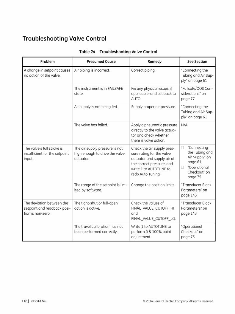
Troubleshooting Valve Control
Table 24 Troubleshooting Valve Control
Problem Presumed Cause Remedy See Section
A change in setpoint causes no action of the valve.
Air piping is incorrect. Correct piping. “Connecting the Tubing and Air Sup-ply” on page 61
The instrument is in FAILSAFE state.
Fix any physical issues, if applicable, and set back to AUTO.
“Failsafe/OOS Con-siderations” on page 77
Air supply is not being fed. Supply proper air pressure. “Connecting the Tubing and Air Sup-ply” on page 61
The valve has failed. Apply a pneumatic pressure directly to the valve actua-tor and check whether there is valve action.
N/A
The valve’s full stroke is insufficient for the setpoint input.
The air supply pressure is not high enough to drive the valve actuator.
Check the air supply pres-sure rating for the valve actuator and supply air at the correct pressure, and write 1 to AUTOTUNE to redo Auto Tuning.
“Connecting the Tubing and Air Supply” on page 61“Operational Checkout” on page 75
The range of the setpoint is lim-ited by software.
Change the position limits. “Transducer Block Parameters” on page 143
The deviation between the setpoint and readback posi-tion is non-zero.
The tight-shut or full-open action is active.
Check the values of FINAL_VALUE_CUTOFF_HI and FINAL_VALUE_CUTOFF_LO.
“Transducer Block Parameters” on page 143
The travel calibration has not been performed correctly.
Write 1 to AUTOTUNE to perform 0 & 100% point adjustment.
“Operational Checkout” on page 75
© 2014 General Electric Company. All rights reserved.118 | =GE Oil & Gas

The valve oscillates cyclically (limit cycle).
The friction of packing is large. 1) Write 1 to AUTOTUNE to redo auto tuning.
2) Use the actuator of proper size.
“Operational Checkout” on page 75
There’s air leak from the pipe of output pressure, or feedback lever is not correctly attached.
Check the piping and attachment of the lever, and write 1 to AUTOTUNE to redo Auto Tuning.
“Installation” on page 44“Operational Checkout” on page 75
Valve responses are too slow.
If only the responses that require air exhaust are slow, it means that the regulator’s max-imum capacity is not large enough.
Replace the regulator. —
The I/P module’s nozzle has become blocked from dirt con-tained in the air supply or the like.
Check whether or not error occurs in XD_ERROR in steady states. If it does occur, contact the nearest service station or represen-tative office.
“Transducer Block Parameters” on page 143
The control relay has become blocked from dirt contained in the air supply or the like.
Check whether or not an error has occurred in XD_ERROR in steady states.
“Transducer Block Parameters” on page 143
The control gain is insufficient. Redo auto tuning. Or, increase the SERVO_GAIN setting.
“Operational Checkout” on page 75“Transducer Block Parame-ters” on page 143
There’s air leak from the pipe of output pressure, or feedback lever is not correctly attached.
Check the piping and attachment of the lever, and write 1 to AUTOTUNE to redo Auto Tuning.
“Installation” on page 44“Operational Checkout” on page 75
Table 24 Troubleshooting Valve Control (Continued)
Problem Presumed Cause Remedy See Section
Masoneilan SVI FF Instruction Manual =| 119© 2014 General Electric Company. All rights reserved.

Troubleshooting Auto Tuning
Table 25 Troubleshooting Auto Tuning
Problem Presumed Cause Remedy See Section
Auto tuning requests are rejected.
The transducer block is not in manual mode.
If POSITION_LIMITS in enabled autotune is rejected.
Another process is started and running.
Change the target mode of the Transducer block to Man.
Disable this parameter.
Wait until the process terminates.
“Transducer Block Parame-ters” on page 143“Transducer Block Parame-ters” on page 143
When auto tuning has fin-ished, the result appears with a value index:
31: Failed actuation32: Control limits pro-tected33: Failed open loop tuning45: P gain below limit46: P gain adjustment above limit55: Bias out of range66: Fill time exceeded77: Exhaust time exceeded88: Parameter out of range.
There is something wrong with the air supply pressure or spring range.
Check whether the mea-sured pressure reading nearly equals the actual pressure. See the descrip-tions for auto tuning.
“Operational Checkout” on page 75“Step 7: Run Auto Tune METHOD” on page 34
There is something wrong with the operation point of the I/P module.
SERVO_OFFSET could not be measured.
If there is nothing wrong with the air supply pressure and piping, contact the nearest service station or representative office.
—
The measured time delay con-stant, hysteresis, and/or slip width of the valve is excessively large.
Check whether they meet the characteristics specified for the valve. See the descriptions for auto tuning.
“Operational Checkout” on page 75“Auto Tuning” on page 48
The span of rotation angle is incorrect or the 50% position deviation from the horizontal level is too large.
Correct the installation and try auto tuning again.
“Installation” on page 44“Operational Checkout” on page 75
The valve hysteresis is large. Carry out manual tuning. -
© 2014 General Electric Company. All rights reserved.120 | =GE Oil & Gas

Troubleshooting Position, Pressure, and Temperature Sensors
Table 26 Troubleshooting Position, Pressure, and Temperature Sensors
Problem Presumed Cause Remedy See Section
The position sensor FINAL_POSITION_VALUE remains unchanged.
The feedback lever is not prop-erly attached.
See the descriptions for positioner installation.
“Installation” on page 44
The position sensor has failed or there is breakage in the cable between the sensor and ampli-fier.
If ADVAL_BW does not change value when the shaft rotates, it may be nec-essary to replace the posi-tion sensor. Contact our nearest representative or service station.
—
The position sensor signal is unstable, or XD_ERROR indi-cates error:
0 No Error16 Unspecified error17 General error18 Calibration error19 Configuration error20 Electronics Failure21 Mechanical Failure22 I/O Failure23 Data Integrity Error24 Software Error25 Algorithm Error
The position sensor has failed or there is breakage in the cable between the sensor and ampli-fier.
It may be necessary to replace the position sensor. Contact the nearest repre-sentative or service station.
—
Masoneilan SVI FF Instruction Manual =| 121© 2014 General Electric Company. All rights reserved.

The pressure sensor signal is unstable, or XD_ERROR indicates error:
0 No Error16 Unspecified error17 General error18 Calibration error19 Configuration error20 Electronics Failure21 Mechanical Failure22 I/O Failure23 Data Integrity Error24 Software Error25 Algorithm Error
The pressure sensor has failed.
Device is only a standard model diagnostics device
It may be necessary to replace the amplifier. Contact the nearest representative or ser-vice station.
Purchase an upgrade.
—
The temperature sensor sig-nal is unstable, or XD_ERROR indicates error:
0 No Error16 Unspecified error17 General error18 Calibration error19 Configuration error20 Electronics Failure21 Mechanical Failure22 I/O Failure23 Data Integrity Error24 Software Error25 Algorithm Error
The temperature sensor has failed.
Device is only a standard model diagnostics device
It may be necessary to replace the amplifier. Contact the nearest representative or ser-vice station.Purchase an upgrade.
—
Table 26 Troubleshooting Position, Pressure, and Temperature Sensors (Continued)
Problem Presumed Cause Remedy See Section
© 2014 General Electric Company. All rights reserved.122 | =GE Oil & Gas

Appendix E. Using the Pushbuttons and Digital Interfaces
Overview
This section describes three ways to communicate, configure, and calibrate the SVI FF. The Smart Valve Interface is truly a smart device capable of:
Streamlining the valve positioning function
Providing diagnostic information
Improving precision of process control
Communicating critical information locally and remotely
The four available communication tools listed below offer increasing levels of functionality.
Local Display and Push Buttons
FF Handheld Communicator
ValVue
Any FF capable host loaded with the DD for the SVI FF
Local Display and Pushbuttons
The most basic and easiest digital interface is the local pushbutton and display option mounted on the SVI FF. It is available at any time and provides immediate local access to most configuration, calibration, and fault messages. It is approved for use in Explosion Proof and Intrinsically Safe installations in Hazardous Areas.
Additionally, in Normal mode the local display scrolls sequentially displaying setpoint, pressure and position information. The display sequences from one variable to the next every 1.5 seconds.
© 2014 General Electric Company. All rights reserved. Masoneilan SVI FF Instruction Manual =| 123

Handheld Communicator
The handheld communicator is a universally available tool that provides all the accessibility of the local button and display. This tool has the functionality to upload and download configurations, enter alphanumeric messages and set the custom characteristic numerical parameters. The GE DPI620 is approved for Intrinsically Safe use in Hazardous Areas in accordance with SVI FF approvals.
ValVue
ValVue combines the power of the PC with the features of the SVI FF for ease of use and automation of positioner operation and full access to all data. ValVue Standard Version is provided with all SVI FF positioners and is recommended for set up, service and maintenance where a PC or laptop is permitted.
Pushbuttons and Local Display
This section covers the optional local interface consisting of the LCD alphanumeric display and pushbuttons. Operation of the SVI FF Digital Valve Positioner as a local device is controlled through the optional device-mounted pushbuttons and digital display, shown in Figure 50 on page 125. Using the display you can read the input signal, valve position, and actuator pressure. The display sequences from one variable to the next every 1.5 seconds.
Using the pushbuttons you can exit from operating mode at any time and step through a menu structure to perform a wide range of operations including BAS SETUP, ADVANCED SETUP, METHOD and MAN POS to configure and calibrate the valve. ValVue is used to perform all diagnostics functions. The pushbuttons do not support diagnostics functions.
The SVI FF has four operational modes: AUTO (normal operating mode) and Manual (manual operating mode and for parameter changes), OOS (block execution stops) and LO modes. The SVI FF also has a mode for handling of faults and power-up: Failsafe.
© 2014 General Electric Company. All rights reserved.124 | =GE Oil & Gas

Pushbuttons
The local pushbuttons are located behind a hinged cover, directly below the display window. To open the cover loosen the screw and swing the cover down. Always re-fasten the cover after use to protect the pushbuttons from environmental contamination.
The three pushbuttons perform the following functions:
Left Button - Marked with *, permits you to select or accept the value or parameter option currently displayed.
Middle Button - Marked –, permits you to move back through the menu structure to the previous item in the menu or decrement the value currently shown in the digital display. When used to decrease a displayed value, holding the button down causes the value to decrease at a faster rate.
Right Button - Marked +, permits you to move forward through the menu structure to the next item in the menu, or to increment the value currently shown in the digital display. When used to increase a displayed value, holding this button down causes the value to increase at a faster rate.
Figure 50 SVI FF Display
An exclamation point (!) in the SVI FF display window indicates that there is instrument status available.
If the pushbuttons are pushed after being locked by ValVue software, the message LOCKED appears. Refer to the ValVue online help for instructions to unlock the pushbuttons.
NOTE
*+
-(Select) (Forward)
(Back)
NOTE
Masoneilan SVI FF Instruction Manual =| 125© 2014 General Electric Company. All rights reserved.

Pushbutton Locks and Configuration-Lock Jumper
Before performing any of these functions with the local display you must first ensure that the pushbuttons are placed in the unlocked mode using ValVue. The positioner ships in the unlocked mode.
The SVI FF offers several levels of plant security. It may be desirable, after initial setup, to lock the pushbuttons so that the SVI FF parameters cannot be inadvertently changed by the buttons. Several levels of software modifiable pushbutton locks are provided.
Hardware Configuration Lock
Additional security is achieved using the hardware configuration-lock jumper shown in Figure 32 on page 65. When set to secure position, shorting the two-pin header, configuration and calibration are not permitted by the local interface or by remote communications. Pushbuttons, ValVue and a handheld are locked out, except to examine configuration, calibration, and position. This is similar to Security Level 1 shown in Table 27.
Table 27 Pushbutton Lock Security Level
Level Access
Allow Local Buttons Buttons on the SVI FF are fully enabled.
Lock Out Local Calibration and Configuration
Use the buttons to perform operations in normal operating mode and manual mode. Do not go to configure or calibrate mode.
Lock Out Local Manual Examine variables in normal operating mode but do not put the valve in manual operating mode. Access to calibrate or configure modes is not available.
Lock Out All Buttons The buttons are disabled.
© 2014 General Electric Company. All rights reserved.126 | =GE Oil & Gas
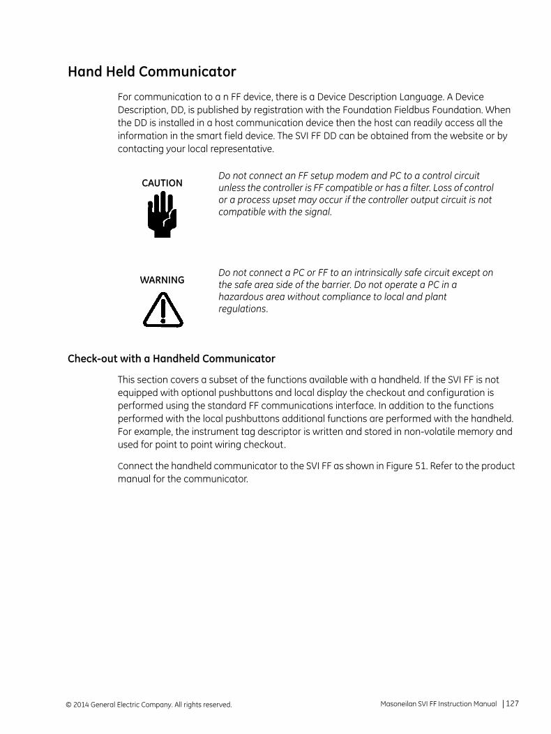
Hand Held Communicator
For communication to a n FF device, there is a Device Description Language. A Device Description, DD, is published by registration with the Foundation Fieldbus Foundation. When the DD is installed in a host communication device then the host can readily access all the information in the smart field device. The SVI FF DD can be obtained from the website or by contacting your local representative.
Check-out with a Handheld Communicator
This section covers a subset of the functions available with a handheld. If the SVI FF is not equipped with optional pushbuttons and local display the checkout and configuration is performed using the standard FF communications interface. In addition to the functions performed with the local pushbuttons additional functions are performed with the handheld. For example, the instrument tag descriptor is written and stored in non-volatile memory and used for point to point wiring checkout.
Connect the handheld communicator to the SVI FF as shown in Figure 51. Refer to the product manual for the communicator.
Do not connect an FF setup modem and PC to a control circuit unless the controller is FF compatible or has a filter. Loss of control or a process upset may occur if the controller output circuit is not compatible with the signal.
Do not connect a PC or FF to an intrinsically safe circuit except on the safe area side of the barrier. Do not operate a PC in a hazardous area without compliance to local and plant regulations.
CAUTION
WARNING
Masoneilan SVI FF Instruction Manual =| 127© 2014 General Electric Company. All rights reserved.
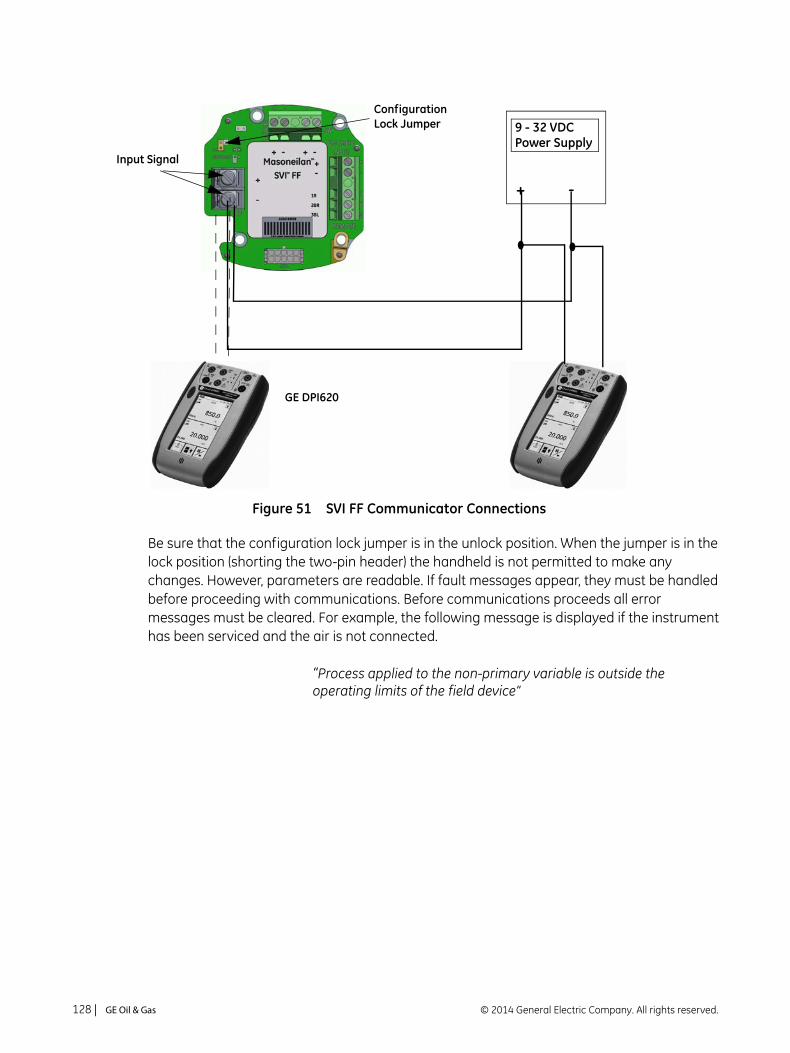
Figure 51 SVI FF Communicator Connections
Be sure that the configuration lock jumper is in the unlock position. When the jumper is in the lock position (shorting the two-pin header) the handheld is not permitted to make any changes. However, parameters are readable. If fault messages appear, they must be handled before proceeding with communications. Before communications proceeds all error messages must be cleared. For example, the following message is displayed if the instrument has been serviced and the air is not connected.
“Process applied to the non-primary variable is outside the operating limits of the field device”
+ -
9 - 32 VDCConfigurationLock Jumper
Input Signal
GE DPI620
Power Supply
© 2014 General Electric Company. All rights reserved.128 | =GE Oil & Gas
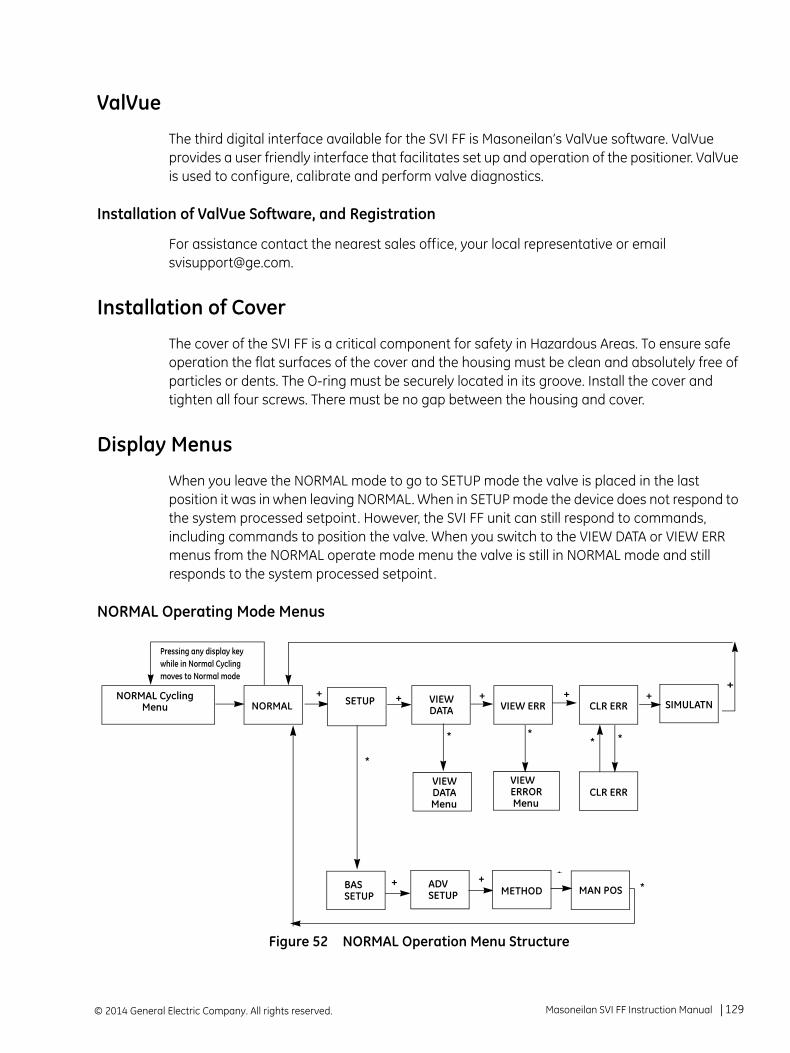
ValVue
The third digital interface available for the SVI FF is Masoneilan’s ValVue software. ValVue provides a user friendly interface that facilitates set up and operation of the positioner. ValVue is used to configure, calibrate and perform valve diagnostics.
Installation of ValVue Software, and Registration
For assistance contact the nearest sales office, your local representative or email [email protected].
Installation of Cover
The cover of the SVI FF is a critical component for safety in Hazardous Areas. To ensure safe operation the flat surfaces of the cover and the housing must be clean and absolutely free of particles or dents. The O-ring must be securely located in its groove. Install the cover and tighten all four screws. There must be no gap between the housing and cover.
Display Menus
When you leave the NORMAL mode to go to SETUP mode the valve is placed in the last position it was in when leaving NORMAL. When in SETUP mode the device does not respond to the system processed setpoint. However, the SVI FF unit can still respond to commands, including commands to position the valve. When you switch to the VIEW DATA or VIEW ERR menus from the NORMAL operate mode menu the valve is still in NORMAL mode and still responds to the system processed setpoint.
NORMAL Operating Mode Menus
Figure 52 NORMAL Operation Menu Structure
NORMAL CyclingMenu NORMAL
VIEWDATA VIEW ERR CLR ERR
VIEWDATAMenu
VIEWERRORMenu
CLR ERR
+++
****
Pressing any display key while in Normal Cycling moves to Normal mode
SETUP +SIMULATN
++
*
BASSETUP
+ ADVSETUP
+METHOD MAN POS
+
*
Masoneilan SVI FF Instruction Manual =| 129© 2014 General Electric Company. All rights reserved.

BAS SETUP Menu
If a change is made in the Air-to-Open / Air-to-Close configuration option or if you move the SVI FF to a different valve or make any change to the valve position linkage, you must run the Find Stops again.
Figure 53 BAS SETUP Menu
ATO
SETUP
+ ++ +*
*
*
Air to....Menu
ATC
*
Characterization
LINEAR
*
*
EQ% 30:1
*
EQ% 50:1
EQ% CAMFX
QUICK50
*
*
CUSTOM
ENGLISH
*
*
FRENCH
+/-
MenuLanguage
Menu
Air to Menu
BAS SETUPBAS SETUP
STOP OPSetting
LanguageMenu +
Select display language.
Select Air To Open (ATO)or Air To Close (ATC). Mustmatch the actuator exactly.
Press * to select option.Press + or - to accept and proceed to next menu item.
Character-
Menu ization
STOP OP
<value>
* - +
Set the percentage value.*
ESPANOL
*
PORTUGUESE
*
Japanese
ITALIAN
*
GERMAN
*
* *
© 2014 General Electric Company. All rights reserved.130 | =GE Oil & Gas

ATO / ATC
The positioner must be configured as Air-to-Open, ATO, or as Air-to-Close, ATC. If the positioner has a double acting relay, the action is defined for the output labeled ACT1, or Output 1.
To determine if a direct acting positioner is considered ATO or ATC perform the following test:
1. Apply the actuators rated pressure to the positioner supply.
2. Disconnect the electrical input signal from the positioner or set it to less than 9 V.
3. Observe the position of the control valve. If it is closed the actuator is ATO. If the valve is open it is ATC.
Valve Characteristics
The positioner must be configured to supply the correct relationship between input signal and valve position. This is called the position characteristic. Table 28 lists configuring the positioner characteristics.
Use of a linear characteristic is recommended unless the process dynamics or control valve application calls for an alternate characteristic. SVI FF offers a custom characteristic for specialty applications. Prior to selection of custom, the parameters for the custom characteristic must be entered using ValVue.
This procedure can cause the valve to move. Before proceeding be sure the valve is isolated from the process. Keep hands clear from moving parts.
Do not exceed actuator pressure rating on the control valve specification sheet. Damage to the valve stem, shaft, or trim can occur.
The characteristic configured in the positioner is applied in addition to the plug characteristic built into the valve trim. Do not configure a percentage characteristic if the valve has a percentage plug.
WARNING
CAUTION
NOTE
Masoneilan SVI FF Instruction Manual =| 131© 2014 General Electric Company. All rights reserved.

Table 28 Guidelines for Characteristic Choice
Valve Type and Built In Characteristic Desired Installed Valve Position Characteristic
Standard Positioner Characteristic Selection
Camflex Linear LINEAR
Camflex Equal Percentage EQUAL50
EQ% CAMFX (when replacing a 4700E)
Varimax Linear LINEAR
Varimax Equal Percentage EQUAL50
21000 series Model # 21X1X or 41000 series Model # 41X1X with LINEAR TRIM
Linear LINEAR
21000 series Model # 21X1X or 41000 series Model # 41X1X with LINEAR TRIM
Equal Percentage EQUAL50
21000 series Model # 21X2X or 41000 series Model # 41X2X with EQUAL PERCENTAGE TRIM
Linear Not Recommended
21000 series Model # 21X2X or 41000 series Model # 41X2X with EQUAL PERCENTAGE TRIM
Equal Percentage LINEAR
Ball Valve with typical MODIFIED PERCENTAGE TRIM Linear Not Recommended
Ball Valve with typical MODIFIED PERCENTAGE TRIM Equal Percentage LINEAR
Butterfly valve with typical MODIFIED PERCENTAGE TRIM
Linear Not Recommended
Butterfly valve with typical MODIFIED PERCENTAGE TRIM
Equal Percentage LINEAR
Reciprocating valve with LINEAR TRIM Linear LINEAR
Reciprocating valve with LINEAR TRIM Equal Percentage EQUAL50
Rotary or Reciprocating valve with EQUAL PER-CENTAGE TRIM
Linear Not recommended
Rotary or Reciprocating valve with EQUAL PER-CENTAGE TRIM
Equal Percentage LINEAR
© 2014 General Electric Company. All rights reserved.132 | =GE Oil & Gas
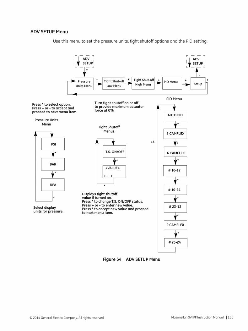
ADV SETUP Menu
Use this menu to set the pressure units, tight shutoff options and the PID setting.
Figure 54 ADV SETUP Menu
Setup++ +
*
*
AUTO PID
*
*
5 CAMFLEX
*
6 CAMFLEX
# 10-12
# 10-24
*
*
# 23-12
PSI
*
*
BAR
KPA
T.S. ON/OFF
*
*
* - +
<VALUE>
+/-
PID Menu
Pressure UnitsMenu
Tight ShutoffMenus
ADV
Pressure Units Menu
PID MenuTight Shut-off Low Menu
+
Displays tight shutoffvalue if turned on.Press * to change T.S. ON/OFF status.Press + or - to enter new value.Press * to accept new value and proceedto next menu item.
Select display units for pressure.
Turn tight shutoff on or offto provide maximum actuatorforce at 0%
Press * to select option.Press + or - to accept and proceed to next menu item.
SETUPADV SETUP
*
9 CAMFLEX
*
# 23-24
*
+Tight Shut-off High Menu
Masoneilan SVI FF Instruction Manual =| 133© 2014 General Electric Company. All rights reserved.

Pressure Units
Select the display units for the optional actuator pressure sensor. The available choices are PSI, BAR or KPA. The choice applies to both the local LCD display and to the displays with ValVue or the a handheld communicator.
Tight Shutoff
Tight Shutoff LO is an optional performance feature that prevents leakage at the closed position. Without this feature, at the closed position with an input signal of 0%, the valve may be forced tight against the seat with maximum available actuator force or it may be only touching the seat with minimum force. In either case, it is under control.
To prevent leakage that can occur in the second case, configure TS LO ON and set a value of position setpoint below which the actuator applies maximum seating force. As the position signal drops toward the TS value, SVI FF moves the valve to the TS position value. When the position reaches the TS value SVI FF applies maximum actuator force.
Tight Shutoff HI is an optional performance feature that prevents leakage at the open position. Without this feature, at the open position with an input signal of 100%, the valve may be forced tightly open with maximum available actuator force or it may be only touching the with minimum force. In either case, it is under control.
To prevent leakage that can occur in the second case, configure TS HI ON and set a value of position setpoint below which the actuator applies maximum seating force. As the position signal approaches the TS value, SVI FF moves the valve to the TS position value. When the position reaches the TS value SVI FF applies maximum actuator force.
For both TS LO and HI, the TS function has 0.5% deadband to prevent chatter. If TS is set ON at 2%, for example, then the valve begins to open when the setpoint reaches 2.5%.
These features are implemented by FINAL_VALUE_CUTOFF_LO or FINAL_VALUE_CUTOFF_HI.
See Appendix H “Notes on Characterization” on page 181 for a discussion of the impact of Characterization on Tight Shutoff settings.
NOTE
© 2014 General Electric Company. All rights reserved.134 | =GE Oil & Gas
VIEW DATA Menu
Use the VIEW DATA menu to read the current configuration, calibration, and status information. This information cannot be changed from the VIEW DATA menu. Figure 55 on page 136 and Figure 56 on page 137 show the available data.
Viewing Configuration and Calibration Parameters
To view configuration and calibration parameters use the following procedure:
1. Press + to move through the options until you reach the VIEW DATA menu.
2. Press * to go to VIEW DATA menu. Press + to select the VIEW DATA mode.
3. To exit from the VIEW DATA menu, press * at any menu line. You return to the last menu displayed.
Masoneilan SVI FF Instruction Manual =| 135© 2014 General Electric Company. All rights reserved.

Figure 55 VIEW DATA Menu Part 1
+
+
SINGLE OR DOUBLE
+
+
PRESSURE UNITS
+
T.S. ON OR T.S.OFF
*
VIEW DATA
ACTUATOR TYPE
VALVE CHARACTERISTICS
LINEAR, EQ% 30:1, EQ% 50:1, EQ% CAMFX, QUICK 50, CUSTOM
PSI, BAR, KPA
TIGHT SHUTOFF
ACTION TYPE
ATO or ATC
+
+
+
VIEW ERR
SVI FF REV
STOP OP
PID Setting
+
+
BACK*
See Figure 56 on page 137 for continuation of View Data menu FF Info
FF INFO
*
© 2014 General Electric Company. All rights reserved.136 | =GE Oil & Gas

Figure 56 VIEW DATA Menu Part 2
*
+
SVI FF REV
FF INFO
*
DEV INFO
+
DEV ADDR
DEV ID
+
Repeat + for Device ID 1... 4Press * for BACK
+ RB
RB INFO
*
RB TAG
+
+
Repeat + for RB TAG 1... 4Press * for BACK
+TB
TB INFO
*
TB TAG
+
BACK
+
*
AO
AO INFO
*
AO TAG
+
BACK
+
*
+ + PID1
PID1 INFO
*
PID1 TAG 1
+
+
*
+ PID2
PID2 INFO
*
BACK
+
*
+
Repeat + for PID1 TAG 2... 4Press * for BACK
DO1
DO1 INFO
*
DO1 TAG
+
*
+
+
BACK
Press + to go to DO2
DEV TAG
Masoneilan SVI FF Instruction Manual =| 137© 2014 General Electric Company. All rights reserved.

VIEW ERROR Menu
Use the VIEW ERROR menu to view actuator and pressure errors.
Figure 57 VIEW ERROR Menu
Table 29 lists the fault codes and messages that appear on the display and explains the message meaning and possible causes.
Error messages depend on the device status and can vary for different devices.
*
VIEW
*
ACT
+
AIR WARN
ERROR
ERROR
BACK *
© 2014 General Electric Company. All rights reserved.138 | =GE Oil & Gas
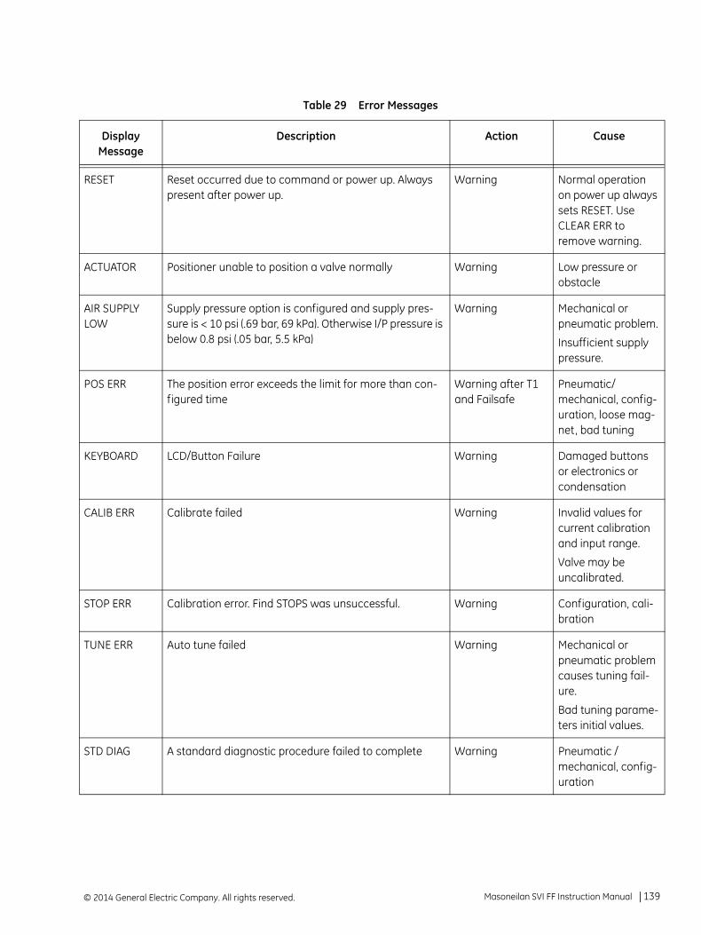
Table 29 Error Messages
Display Message
Description Action Cause
RESET Reset occurred due to command or power up. Always present after power up.
Warning Normal operation on power up always sets RESET. Use CLEAR ERR to remove warning.
ACTUATOR Positioner unable to position a valve normally Warning Low pressure or obstacle
AIR SUPPLY LOW
Supply pressure option is configured and supply pres-sure is < 10 psi (.69 bar, 69 kPa). Otherwise I/P pressure is below 0.8 psi (.05 bar, 5.5 kPa)
Warning Mechanical or pneumatic problem.
Insufficient supply pressure.
POS ERR The position error exceeds the limit for more than con-figured time
Warning after T1 and Failsafe
Pneumatic/ mechanical, config-uration, loose mag-net, bad tuning
KEYBOARD LCD/Button Failure Warning Damaged buttons or electronics or condensation
CALIB ERR Calibrate failed Warning Invalid values for current calibration and input range.
Valve may be uncalibrated.
STOP ERR Calibration error. Find STOPS was unsuccessful. Warning Configuration, cali-bration
TUNE ERR Auto tune failed Warning Mechanical or pneumatic problem causes tuning fail-ure.
Bad tuning parame-ters initial values.
STD DIAG A standard diagnostic procedure failed to complete Warning Pneumatic / mechanical, config-uration
Masoneilan SVI FF Instruction Manual =| 139© 2014 General Electric Company. All rights reserved.
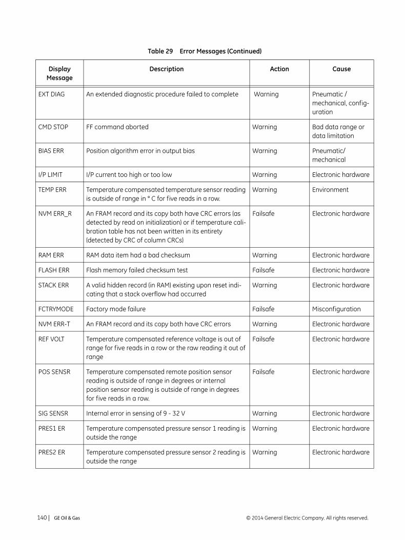
EXT DIAG An extended diagnostic procedure failed to complete Warning Pneumatic / mechanical, config-uration
CMD STOP FF command aborted Warning Bad data range or data limitation
BIAS ERR Position algorithm error in output bias Warning Pneumatic/ mechanical
I/P LIMIT I/P current too high or too low Warning Electronic hardware
TEMP ERR Temperature compensated temperature sensor reading is outside of range in ° C for five reads in a row.
Warning Environment
NVM ERR_R An FRAM record and its copy both have CRC errors (as detected by read on initialization) or if temperature cali-bration table has not been written in its entirety (detected by CRC of column CRCs)
Failsafe Electronic hardware
RAM ERR RAM data item had a bad checksum Warning Electronic hardware
FLASH ERR Flash memory failed checksum test Failsafe Electronic hardware
STACK ERR A valid hidden record (in RAM) existing upon reset indi-cating that a stack overflow had occurred
Warning Electronic hardware
FCTRYMODE Factory mode failure Failsafe Misconfiguration
NVM ERR-T An FRAM record and its copy both have CRC errors Warning Electronic hardware
REF VOLT Temperature compensated reference voltage is out of range for five reads in a row or the raw reading it out of range
Failsafe Electronic hardware
POS SENSR Temperature compensated remote position sensor reading is outside of range in degrees or internal position sensor reading is outside of range in degrees for five reads in a row.
Failsafe Electronic hardware
SIG SENSR Internal error in sensing of 9 - 32 V Warning Electronic hardware
PRES1 ER Temperature compensated pressure sensor 1 reading is outside the range
Warning Electronic hardware
PRES2 ER Temperature compensated pressure sensor 2 reading is outside the range
Warning Electronic hardware
Table 29 Error Messages (Continued)
Display Message
Description Action Cause
© 2014 General Electric Company. All rights reserved.140 | =GE Oil & Gas

Display and Clear Error Messages
Use this procedure, VIEW ERR, to view fault codes and messages listed in Table 29 of this manual.
1. Press + in NORMAL mode to move through the options until you reach the VIEW ERR menu item.
2. Press * to go to VIEW ERR menu.
3. Press * to display the list of status values.
4. Press + to move forward trough the list in sequence.
5. Press – to move back through the list.
6. Press * at any status message to return to the VIEW ERR option.
7. Press + to move to Clear ERR.
8. Press * to clear all messages.
PRES3 ER Temperature compensated pressure sensor 4 (supply) reading is outside of range.
Warning Electronic hardware
PRES4 ER Temperature compensated pressure sensor 4 (pilot) reading is outside of range.
Failsafe Electronic hardware
PRES5 ER Temperature compensated pressure sensor 5 reading is outside the range
Warning Electronic hardware
NVM ERR-W Writer to FRAM fails or data repairing in FRAM fails Warning Electronic hardware
IRQ FAULT Valid hidden record (in RAM) existing upon reset that indicates that an illegal interrupt occurred
Warning Electronic hardware
DATA ERR Internal software error data overrun Failsafe CPU/firmware
MCU ERR 1 Micro-Controller Self Check failed Failsafe Electronic hardware
SW ERR Software self check error Failsafe CPU/firmware
Table 29 Error Messages (Continued)
Display Message
Description Action Cause
Masoneilan SVI FF Instruction Manual =| 141© 2014 General Electric Company. All rights reserved.
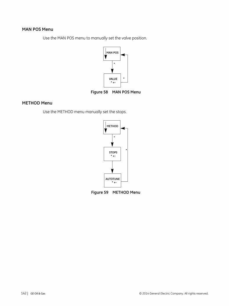
MAN POS Menu
Use the MAN POS menu to manually set the valve position.
Figure 58 MAN POS Menu
METHOD Menu
Use the METHOD menu manually set the stops.
Figure 59 METHOD Menu
*
MAN POS
*VALUE* +-
*
METHOD
STOPS* +-
AUTOTUNE* +-
*
© 2014 General Electric Company. All rights reserved.142 | =GE Oil & Gas

Appendix F. Transducer Block Parameters
Table 30 lists the Transducer block parameters.
Table 30 Transducer Block Parameters
Index Name Range Initial Value
Mode Description
0 BLOCK_INFO
1 Block Tag Block tag is detected by the application is use.
2 DD_MEMBER 0 DD member ID defined by DD tokenizer, when the DD is created (constant)
3 DD ITEM 20018 DD member ID defined by DD tokenizer, when the DD is created (constant)
4 DD REVIS 0x0001 DD revision
5 Profile 8060 Hardcoded to Custom Transducer Block (constant)
6 Profile Revision 01
7 Execution Time 0 0 indicates that this block does not need to be scheduled (constant)
8 EXECUTION_PERIOD
0 0 indicates that this block does not need to be sched-uled.
9 Number of Parameters
120 Number of parameters in the block
10 NEXT_FB_TO_EXECUTE
0 Next block for execution. Not used in this application.
11 VIEWS_INDEX 20010 Starting index of the views.
12 NUMBER_VIEW_3 6 1 - Indicates how many View3s are used. See “Views” on page 189.
13 NUMBER_VIEW_4 5 1 - Indicates how many View4s are used. “Views” on page 189.
1 ST_REV 1-0xFFFF 0 The revision level of the static data associated with the function block.
© 2014 General Electric Company. All rights reserved. Masoneilan SVI FF Instruction Manual =| 143

2 TAG_DESC
The user description of the intended application of the block.
3 STRATEGY 0 The strategy field can be used to identify grouping of blocks. This data is not checked or processed by the block
4 ALERT_KEY [1, 255] 0 The identification number of the plant unit. This informa-tion may be used in the host for sorting alarms, etc.
5 MODE_BLK MODE_BLK
1 TARGET See Description
Auto Will be limited to set only one of the PERMITTED modes. See “Block Modes” on page 18.
2 ACTUAL Will reflect the actual block mode for the device. See “Block Modes” on page 18.
3 PERMITTED Auto, MAN, OOS
The following list indicates what will be the list of permit-ted bit values:0x80 - Out of Service Mode0x10 - Manual0x04 - Auto ModeAll other bits will be filtered and ignored.
4 NORMAL Auto
6 BLOCK_ERR
7 UPDATE_EVT This alert is generated by any change to the static data. Update event will be generated each time a static parameter attribute value is changed
1 UNACKNOWL-EDGED
Standard FF Alarm Behavior. 0 = Undefined 1 = Acknowledged 2 = Unacknowledged
2 UPDATE_STATE Standard FF Alarm Behavior 0 = Undefined 1 = Update reported 2 = Update not reported
3 TIME_STAMP Standard FF Alarm Behavior. The time when the parame-ter was updated.
4 STATIC_REVISION
Standard FF Alarm Behavior
5 RELATIVE_INDEX Standard FF Alarm Behavior. The relative OD index of the static parameter whose change caused this alert.
8 BLOCK_ALM The block alarm is used for all configuration, hardware, connection failure or system problems in the block. The cause of the alert is entered in the sub code field. The first alert to become active will set the Active status in the Status attribute. As soon as the Unreported status is cleared by the alert reporting task, another block alert may be reported without clearing the Active status, if the sub code has changed
Table 30 Transducer Block Parameters (Continued)
© 2014 General Electric Company. All rights reserved.144 | =GE Oil & Gas
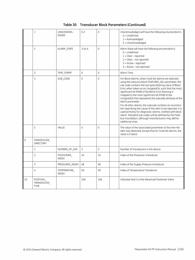
1 UNACKNOWL-EDGED
0-2 0 Unacknowledged will have the following enumeration’s: 0 = Undefined 1 = Acknowledged 2 = Unacknowledged
2 ALARM_STATE 0 to 4 0 Alarm State will have the following enumeration’s: 0 = Undefined 1 = Clear - reported 2 = Clear - not reported 3 = Active - reported 4 = Active - not reported
3 TIME_STAMP 0 0 Alarm Time
4 SUB_CODE 0 0 For Block Alarms, when multi-bit alarms are selected using the resource block FEATURES_SEL parameter, the sub code contains the two byte bitstring value of Block Error when taken as an Unsigned16, such that the most significant bit (MSB) of the Block Error bitstring is mapped to the most significant bit (MSB) of the Unsigned16 that represents the subcode attribute of the Alarm parameter.For all other alarms, the subcode contains an enumera-tion specifying the cause of the alert to be reported. It is used primarily for diagnostic alarms, notified with block alarm. Standard sub codes will be defined by the Field-bus Foundation, although manufacturers may define additional ones.
5 VALUE 0 0 The value of the associated parameter at the time the alert was detected, except that for multi-bit alarms, the value is 0 (zero).
9 TRANSDUCER_DIRECTORY
1 NUMBER_OF_XDS 3 3 Number of transducers in the device
2 POSITIONER_INDEX
10 10 Index of the Positioner transducer.
3 PRESSURES_INDEX 48 48 Index of the Supply Pressure transducer
4 TEMPERATURE_INDEX
59 59 Index of Temperature Transducer
10 POSITION_TRANSDUCER_TYPE
106 106 Indicates that it is the Advanced Positioner Valve
Table 30 Transducer Block Parameters (Continued)
Masoneilan SVI FF Instruction Manual =| 145© 2014 General Electric Company. All rights reserved.

11 XD_ERROR_POS 0 0 The Following errors can be reported in XD_ERROR parameter: 0 No Error 16 Unspecified error (to be mapped to Other in Block Error 17 General error 18 Calibration error 19 Configuration error 20 Electronics Failure 21 Mechanical Failure 22 I/O Failure 23 Data Integrity Error 24 Software Error 25 Algorithm Error
12 FINAL_VALUE
The requested valve position and setpoint status written by an Analog Output block. The output is used as the set-point when controlled in Man mode.
1 STATUS The status written by the Analog Output FB.
2 VALUE The requested valve position, written by the AO FB
13 FINAL_VALUE_RANGE
Man The range of the FINAL_VALUE (setpoint) and the FINAL_VALUE_RANGE (actual position).This parameter is not changeable.
1 EU_100 100 100 Max Position value at 100%. Fixed to 100.
2 EU_0 0 0 Min Position value at 100%. Fixed to 0.
3 UNITS_INDEX %(1342) %(1342) Engineering Units at 100. Fixed to %(1342)
4 DECIMAL 2 2 2
14 POSITION_LIMITS Man Position Limits defined as percentage of valve travel.
1 LIMITS_PROTECTED
T/F F Position Limits change is restricted. If True, ENABLE_HI and ENABLE_LO cannot be changed. This should be set to False before running diagnostic procedures.
2 ENABLE_HI T/F F Position Limit HI enabled
3 ENABLE_LO T/F F Position Limit LO enabled
4 LIMIT_HI -25to+125 125 Position Limit HI Point. The working setpoint is limited be this value.
5 LIMIT_LO -25to+125 -25 Position Limit LO Point
6 ENABLE_RATE_HI T/F F Enables working setpoint Position Rate Limit when the valve setpoint increased.
7 ENABLE_RATE_LO T/F F Enables working setpoint Position Rate Limit when the valve setpoint decreased.
8 LIMIT_RATE 0.5 to 100.1 100.1 Position Rate Limit
15 FINAL_VALUE_CUTOFF_HI
If the working position is higher than this value, the valve is forced to its maximum high value (fully opened).
1 ENABLE T/F F Man True if CUTOFF_HI algorithm to be enabled
2 CUTOFF_POINT_HI >=80% 98 Man Cut-Off point HI. Valve will be fully open to after this point. From 80% to 200%
Table 30 Transducer Block Parameters (Continued)
© 2014 General Electric Company. All rights reserved.146 | =GE Oil & Gas

16 FINAL_VALUE_CUTOFF_LO
If the working position is less than this value, the valve is forced to its maximum low value (fully closed).
1 ENABLE T/F F Man True if CUTOFF_LO algorithm to be enabled
2 CUTOFF_POINT_LO
<=20% 2 Man Cut-Off point LO. Valve will be fully closed to after this point. Below 20% to at least -50%
17 FINAL_POSITION_VALUE
The actual valve position and status.
1 STATUS
2 VALUE Actual position value
18 ACTIVATE_CONTROL_SET
0,1,2,3,4,5,6,7,10,11, 255
0 Auto Allows copying of the Working Control Set or the Backup Control Set to the Active control set. The following com-mands are available: 0: Activate Custom Control Set 1: Activate Control Set 1(Slowest) 2: Activate Control Set 2 3: Activate Control Set 3 4: Activate Control Set 4 5: Activate Control Set 5(Fastest) 6: Activate Control Set 6 (Double Acting - Slow) 7: Activate Control Set 7 (Double Acting- Fast)
10: Restore Control set (make Backup Control Set Active) 11: Make active control set as Custom control set
255: Do NothingSee Table 2 on page 47 and Table 3 on page 47 for tables recommending control sets by valve.
19 ACTIVE_CONTROL_SET
This read-only parameter contains the control parame-ters currently used by the positioner.
1 Selector NA Identifies the active control set
2 P NA
3 I NA
4 D NA
5 Padj NA
6 Beta NA
7 PosComp NA
8 DeadZone NA
9 NonLin NA
20 CUSTOM_CONTROL_SET
User editable values. These values will not change the active control set until ACTIVATE_CONTROL_SET is not set to 0.
1 P max. 5000 Auto
Table 30 Transducer Block Parameters (Continued)
Masoneilan SVI FF Instruction Manual =| 147© 2014 General Electric Company. All rights reserved.

2 I max. 1000 Auto
3 D max. 200 Auto
4 Padj [-3000,3000]
Auto
5 Beta [-9, 9] Auto
6 PosComp [2, 20] Auto
7 DeadZone max. 821 Auto
8 NonLin [0,20] Auto
21 BACKUP_CONTROL_SET
Values before the last control set was activated.
1 Selector NA
2 P NA
3 I NA
4 D NA
5 Padj NA
6 Beta NA
7 PosComp NA
8 DeadZone NA
9 NonLin NA
22 TRAVEL CALIBRATION
The location of last positioner calibration. This describes the physical location at which the calibration was per-formed. (ex. NIST, Acme Labs).
1 CAL_LOCATION See Description
Auto The location of last positioner calibration. This describes the physical location at which the calibration was per-formed.
2 CAL_DATE See Description
Auto The date of the last positioner calibration.
3 CAL_WHO See Description
Auto The name of the person responsible for the last posi-tioner calibration.
4 STOP_HI_POS 0-FFFFFFFF 0 Auto Calibration Point HI: Will be set when the calibration pro-cedure is invoked. Provides the temperature compen-sated position, as reported by the sensor. Value is not valid if TRAVEL_CALIBRATION.LAST_RESULT is not Success
5 STOP_LO_POS 0-FFFFFFFF 0 Auto Calibration Point LO: Will be set when the calibration pro-cedure is invoked. Provides the temperature compen-sated position, as reported by the sensor. Value is not valid if TRAVEL_CALIBRATION.LAST_RESULT is not Suc-cess
Table 30 Transducer Block Parameters (Continued)
© 2014 General Electric Company. All rights reserved.148 | =GE Oil & Gas
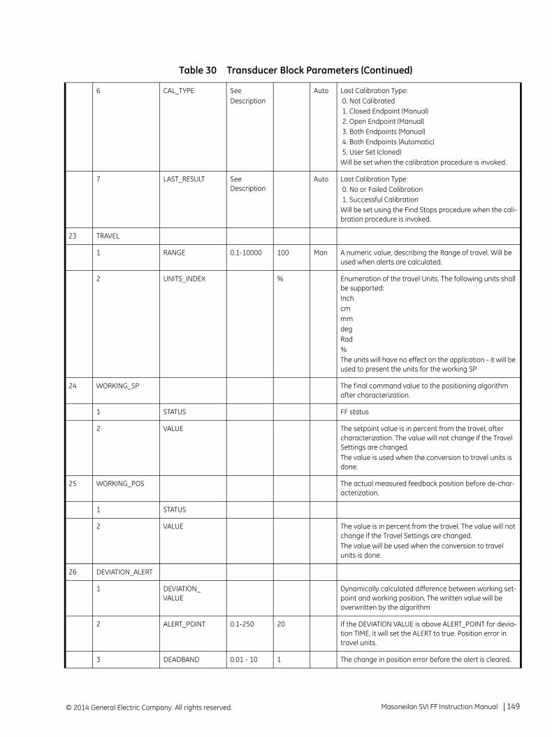
6 CAL_TYPE SeeDescription
Auto Last Calibration Type: 0. Not Calibrated 1. Closed Endpoint (Manual) 2. Open Endpoint (Manual) 3. Both Endpoints (Manual) 4. Both Endpoints (Automatic) 5. User Set (cloned)Will be set when the calibration procedure is invoked.
7 LAST_RESULT See Description
Auto Last Calibration Type: 0. No or Failed Calibration 1. Successful CalibrationWill be set using the Find Stops procedure when the cali-bration procedure is invoked.
23 TRAVEL
1 RANGE 0.1-10000 100 Man A numeric value, describing the Range of travel. Will be used when alerts are calculated.
2 UNITS_INDEX % Enumeration of the travel Units. The following units shall be supported:InchcmmmdegRad%The units will have no effect on the application - it will be used to present the units for the working SP
24 WORKING_SP The final command value to the positioning algorithm after characterization.
1 STATUS FF status
2 VALUE The setpoint value is in percent from the travel, after characterization. The value will not change if the Travel Settings are changed.The value is used when the conversion to travel units is done.
25 WORKING_POS The actual measured feedback position before de-char-acterization.
1 STATUS
2 VALUE The value is in percent from the travel. The value will not change if the Travel Settings are changed.The value will be used when the conversion to travel units is done.
26 DEVIATION_ALERT
1 DEVIATION_VALUE
Dynamically calculated difference between working set-point and working position. The written value will be overwritten by the algorithm
2 ALERT_POINT 0.1-250 20 If the DEVIATION VALUE is above ALERT_POINT for devia-tion TIME, it will set the ALERT to true. Position error in travel units.
3 DEADBAND 0.01 - 10 1 The change in position error before the alert is cleared.
Table 30 Transducer Block Parameters (Continued)
Masoneilan SVI FF Instruction Manual =| 149© 2014 General Electric Company. All rights reserved.

4 TIME From 0 - 3600
20 The user defined allowable duration in seconds of devia-tion before alert. When presented to the user, the value should be in sec-onds and limited between 1s to 60 minutes (3600s)
5 ALERT 0 0 TRUE if DEVIATION VALUE is bigger than DEVIATION_ALERT_POINT for DEVIATION_TIMEFALSE if DEVIATION_VALUE is smaller than (DEVIATION_ALERT+DEVIATION_DEADBAND)
6 HISTORIC ALERT 0 0 TRUE if ALERT is trueNot Changed if ALERT is false
7 ENABLE 0 TRUE True - Enables the ALERT to be reported according to the configuration False - Disables ALERT reporting
27 POSITION_HIHI_ALERT
1 POSITION Current valve position in travel units.
2 ALERT_POINT 110 POSITION Value, above which the ALERT will be set to True. Should be set above POSITION_HI_ALERT.ALERT_POINT.
3 DEADBAND 1 POSITION change, required to clear the ALERT, once it was set to True
4 ALERT 0 True if the position has reached above ALERT_POINT and have not come below (ALERT_POINT-DEADBAND)
5 HISTORIC ALERT 0 True if ALERT is trueNot Changed if ALERT is false
6 ENABLE TRUE TRUE True - Enables the ALERT to be reported according to the configuration False - Disables ALERT reporting
28 POSITION_HI_ALERT
1 POSITION Current valve position in travel units. Presented here for convenience.
2 ALERT_POINT 105 POSITION Value, above which the ALERT will be set to True. Should be set above POSITION_LO_ALERT.ALERT_POINT.
3 DEADBAND 1 POSITION change, required to clear the ALERT, once it was set to True
4 ALERT 0 True if the position has reached above ALERT_POINT and have not come below (ALERT_POINT-DEADBAND)
5 HISTORIC ALERT 0 True if ALERT is trueNot Changed if ALERT is false
6 ENABLE TRUE TRUE True - Enables the ALERT to be reported according to the configuration False - Disables ALERT reporting
29 POSITION_LO_ALERT
Table 30 Transducer Block Parameters (Continued)
© 2014 General Electric Company. All rights reserved.150 | =GE Oil & Gas

1 POSITION Current valve position in travel units. Presented here for convenience.
2 ALERT_POINT -51 to 199 -5 POSITION Value, below which the ALERT will be set to True. Should be set below POSITION_HI_ALERT.ALERT_POINT
3 DEADBAND 0.1-10 1 POSITION change, required to clear the ALERT, once it was set to True
4 ALERT 0 0 True if the position has reached below ALERT_POINT and have not come above (ALERT_POINT+DEADBAND)
5 HISTORIC ALERT 0 0 True if ALERT is trueNot Changed if ALERT is false
6 ENABLE 0 TRUE True - Enables the ALERT to be reported according to the configuration False - Disables ALERT reporting
30 POSITION_LOLO_ALERT
1 POSITION Current valve position in travel units. Presented here for convenience.
2 ALERT_POINT -51 to 199 -10 POSITION Value, below which the ALERT will be set to True. Should be set below POSITION_LO_ALERT.ALERT_POINT
3 DEADBAND 0.1-10 1 POSITION change, required to clear the ALERT, once it was set to True
4 ALERT 0 0 True if the position has reached below ALERT_POINT and have not come above (ALERT_POINT+DEADBAND)
5 HISTORIC ALERT 0 0 True if ALERT is trueNot Changed if ALERT is false
6 ENABLE 0 TRUE True - Enables the ALERT to be reported according to the configuration False - Disables ALERT reporting
31 TRAVEL_ACCUMULATION_A_ALERT
1 TRAVEL_ACCUMULATION
0 Totalized change in travel, since the TRAVEL_ACCUMULATION was cleared. The value will increment when the magnitude of the change exceeds the DEADBAND.
2 ALERT_POINT 0-0xFFFFFFFF
1Milion Travel accumulation value, above which the ALERT is set to True
3 DEADBAND_AB 0.1-10 1 POSITION change, required to exceed, before the TRAVEL ACCUMULATION is increased
4 ALERT 0 0 True if the TRAVEL_ACCUMULATION is above ALERT_POINT.
5 HISTORIC ALERT 0 0 True if ALERT is trueNot Changed if ALERT is false
Table 30 Transducer Block Parameters (Continued)
Masoneilan SVI FF Instruction Manual =| 151© 2014 General Electric Company. All rights reserved.

6 ENABLE 0 TRUE True - Enables the ALERT to be reported according to the configuration False - Disables ALERT reporting
32 TRAVEL_ACCUMULATION_B_ALERT
1 TRAVEL_ACCUMULATION
0 Totalized change in travel, since the TRAVEL_ACCUMULATION was cleared. The value will increment when the magnitude of the change exceeds the DEADBAND.
2 ALERT_POINT 0-0xFFFFFFFF
1Milion Travel accumulation value, above which the ALERT is set to True
3 DEADBAND_AB
0.1-10 1 POSITION change, required to exceed, before the TRAVEL ACCUMULATION is increased
4 ALERT 0 0 True if the TRAVEL_ACCUMULATION is above ALERT_POINT.
5 HISTORIC ALERT 0 0 True if ALERT is trueNot Changed if ALERT is false
6 ENABLE 0 TRUE True - Enables the ALERT to be reported according to the configuration False - Disables ALERT reporting
33 TRAVEL_ACCUMULATION_TREND
The total change in travel trend. The value will increment when the magnitude of the change exceeds the TRAVEL_ACCUMULATION_ALERT.DEADBAND.
1 CURRENTLY COLLECTED
0 Travel accumulation for the current 24 hours period.
2 TODAY(FULL DAY) 0 Travel accumulation for the last full 24 hours period.
3 LAST_DAY 0 Travel accumulation for the previous full 24 hours period.
4 PREVIOUS_DAY 0 Travel accumulation for the previous full 24 hours period.
5 THREE_DAYS_AGO 0 Travel accumulation for the last three days current week
6 CURRENT_WEEK 0 Travel accumulation for the current week
7 LAST_WEEK 0 Travel accumulation for the last full week
8 PREVIOUS_WEEK 0 Travel accumulation for the previous week (2 weeks ago)
9 THREE_WEEKS_AGO
0 Travel accumulation for the past 3 weeks
10 CURRENT_MONTH 0 Travel accumulation for the current month period
11 LAST_MONTH 0 Travel accumulation for the last full month period
12 PREVIOUS_MONTH 0 Travel accumulation for the previous full month period
13 THREE_MONTHS_AGO
0 Travel accumulation for the past 3 months
14 CURRENT_12_MONTHS
0 Travel accumulation for the current 12 month period
15 LAST_12_MONTHS 0 Travel accumulation for the last full 12 months
Table 30 Transducer Block Parameters (Continued)
© 2014 General Electric Company. All rights reserved.152 | =GE Oil & Gas

16 PREVIOUS_12_MONTHS
0 Travel accumulation for the previous full 12 months
17 THREE_YEARS_AGO
0 Travel accumulation for the 3 years ago
34 CYCLE_COUNTER_A_ALERT
1 CYCLE_COUNTER 0 Number of times the travel changes the direction
2 ALERT_POINT 10000 CYCLE_COUNTER Value, above which the ALERT_POINT will set the ALERT to True
3 DEADBAND_AB 0.05-10 1 POSITION change, required to exceed, before the CYCLE_COUNTER is increased
4 ALERT 0 0 True if CYCLE_COUNTER is above ALERT_POINT
5 HISTORIC ALERT 0 0 True if ALERT is trueNot Changed if ALERT is false
6 ENABLE 0 0 True - Enables the ALERT to be reported according to the configuration False - Disables ALERT reporting
35 CYCLE_COUNTER_B_ALERT
1 CYCLE_COUNTER 0 Number of times the travel changes the direction
2 ALERT_POINT 10000 CYCLE_COUNTER Value, above which the ALERT_POINT will set the ALERT to True
3 DEADBAND_AB 0.05-10 1 POSITION change, required to exceed, before the CYCLE_COUNTER is increased
4 ALERT 0 0 True if CYCLE_COUNTER is above ALERT_POINT
5 HISTORIC ALERT 0 0 True if ALERT is trueNot Changed if ALERT is false
6 ENABLE 0 0 True - Enables the ALERT to be reported according to the configuration False - Disables ALERT reporting
36 CYCLE_COUNTER_TREND
The number of times the travel changes direction. The value will increment when the magnitude of the change exceeds the CYCLE_COUNTER_ALERT.DEADBAND.
1 CURRENTLY COLLECTED
0 Cycles for the current 24 hours period.
2 TODAY(FULL DAY) 0 Cycles for the last full 24 hours period.
3 LAST_DAY 0 Cycles for the previous full 24 hours period.
4 PREVIOUS_DAY 0 Cycles for the previous full 24 hours period.
5 THREE_DAYS_AGO 0 Cycles for the past three days
6 CURRENT_WEEK 0 Cycles for the current week
7 LAST_WEEK 0 Cycles for the last full week
8 PREVIOUS_WEEK 0 Cycles for the previous week (2 weeks ago)
Table 30 Transducer Block Parameters (Continued)
Masoneilan SVI FF Instruction Manual =| 153© 2014 General Electric Company. All rights reserved.

9 THREE_WEEKS_AGO
0 Cycles for 3 weeks past
10 CURRENT_MONTH 0 Cycles for the current month period
11 LAST_MONTH 0 Cycles for the last full month period
12 PREVIOUS_MONTH 0 Cycles for the previous full month period
13 THREE_MONTHS_AGO
0 Cycles 3 months past
14 CURRENT_12_MONTHS
0 Cycles for the current 12 month period
15 LAST_12_MONTHS 0 Cycles for the last full 12 months
16 PREVIOUS_12_MONTHS
0 Cycles for the previous full 12 months
17 THREE_YEARS_AGO
0 Cycles for 3 years past
37 POSITION_ERROR_TREND
Trend of the position error.
1 CURRENTLY COLLECTED
0 Position Error for the current time less than 24 hours period.
2 TODAY (FULL DAY) 0 Position Error for the last full 24 hours period.
3 LAST_DAY 0 Position Error for the previous full 24 hours period.
4 PREVIOUS_DAY 0 Position Error for the previous full 24 hours period.
5 THREE_DAYS_AGO 0 Position Error for the previous full 24 hours period.
6 CURRENT_WEEK 0 Position Error for the current week
7 LAST_WEEK 0 Position Error for the last full week
8 PREVIOUS_WEEK 0 Position Error for the previous week (2 weeks ago).
9 THREE_WEEKS_AGO
0 Position Error 3 weeks ago.
10 CURRENT_MONTH 0 Position Error for the current month period.
11 LAST_MONTH 0 Position Error for the last full month period.
12 PREVIOUS_MONTH 0 Position Error for the previous full month period.
13 THREE_MONTHS_AGO
0 Position Error 3 months ago
14 CURRENT_12_MONTHS
0 Position Error for the current 12 month period.
15 LAST_12_MONTHS 0 Position Error for the last full 12 months
16 PREVIOUS_12_MONTHS
0 Position Error for the previous full 12 months
17 THREE_YEARS_AGO
0 Position Error 3 years ago
Table 30 Transducer Block Parameters (Continued)
© 2014 General Electric Company. All rights reserved.154 | =GE Oil & Gas

38 POSITION_HISTOGRAM
An array of counters that will count how many macro cycles the valve was in different position segments. The counters should increase only if the device is under con-trol - the transducer block is in AUTO mode and the qual-ity of the set point is GOOD.
1 TOTAL_TIME 0 Total Working time in seconds or time since the reset to the values in the histogram
2 5%-CLOSED 0 Macrocyles in the range from closed to 5%.
3 10% 0 Macrocyles below 10%.
4 20% 0 Macrocyles between 10% and 20%.
5 30% 0 Macrocyles between 20% and 30%.
6 40% 0 Macrocyles between 30% and 40%.
7 50% 0 Macrocyles between 40% and 50%.
8 60% 0 Macrocyles between 50% and 60%.
9 70% 0 Macrocyles between 60% and 70%.
10 80% 0 Macrocyles between 70% and 80%.
11 90% 0 Macrocyles between 80% and 90%.
12 95% 0 Macrocyles between 90% and 95%.
13 95%-OPEN 0 Number of macrocycles spent in the 95% to Open range.
39 NEAR_CLOSED_ALERT
The near closed alert will be reported only if the valve had been working with a valid set point and in auto mode.The Near Closed alert will NOT count if the device is in Tight Closed Condition
1 POINT_CLOSED
- 49 to 100 5 Point, below which the valve is considered Near Closed
2 NEAR_CLOSED 0 Time in hours the valve spends in near closed position (POINT_CLOSED-CLOSED) under control (in Manual, Auto or LO modes)
3 ALERT_POINT 2000 2000 Value in hours, above which will set the ALERT to True
4 ALERT 0 0 True if NEAR_CLOSED is above ALERT_POINT
5 HISTORIC ALERT 0 0 True if ALERT is trueNot Changed if ALERT is false
6 ENABLE 0 TRUE True - Enables the ALERT to be reported according to the configuration False - Disables ALERT reporting
40 POSITION_ERROR_HISTOGRAM
An array of counters that defines average position error in each region. The values will be calculated only if the device is under control - and the quality of the set point is GOOD.
1 5%-CLOSED 0 Average position error in the range between closed and 5%.
2 10% 0 Average position error in the range below 10%.
Table 30 Transducer Block Parameters (Continued)
Masoneilan SVI FF Instruction Manual =| 155© 2014 General Electric Company. All rights reserved.

3 20% 0 Average position error in the range between 10% and 20%.
2 30% 0 Average position error in the range between 20% and 30%.
3 40% 0 Average position error in the range between 30% and 40%.
4 50% 0 Average position error in the range between 40% and 50%.
5 60% 0 Average position error in the range between 50% and 60%.
6 70% 0 Average position error in the range between 60% and 70%.
7 80% 0 Average position error in the range between 70% and 80%.
8 90% 0 Average position error in the range between 80% and 90%.
9 95% 0 Average position error in the range between 90% and 95%.
11 95%-OPEN 0 Average position error in the range between 95% and open.
41 SETPOINT_TIMEOUT_ALERT
The setpoint update alert will be reported only if the valve setpoint has not been updated by the AO or DO block for more than ALERT_POINT time.
1 TIME_SINCE_UPDATE
>0 0 Time since the last update from the AO or DO block.
2 ALERT_POINT >0.5 20 Value, above which will set the ALERT to True. Note, that this time must be at least 2 times bigger than the macro cycle.
3 MAX_TIME >=0 0 Maximal Time Detected before the setpoint is updated
4 ALERT 0 0 True if TIME_SINCE_UPDATE is above ALERT_POINT
5 HISTORIC ALERT 0 0 True if ALERT is trueNot Changed if ALERT is false
6 ENABLE 0 TRUE True - Enables the ALERT to be reported according to the configuration False - Disables ALERT reporting
42 XD_FSTATE Fault state action configuration.
1 CONFIGURATION 1,2 1 All Defines the source for configuration: 1: One time Copy FSTATE_TIME, FSTATE_VALUE and FSTATE_OPT from Analog output block. This is temporary configuration, and the value goes back to 2 (Indepen-dent) 2: Independent Configuration
Table 30 Transducer Block Parameters (Continued)
© 2014 General Electric Company. All rights reserved.156 | =GE Oil & Gas
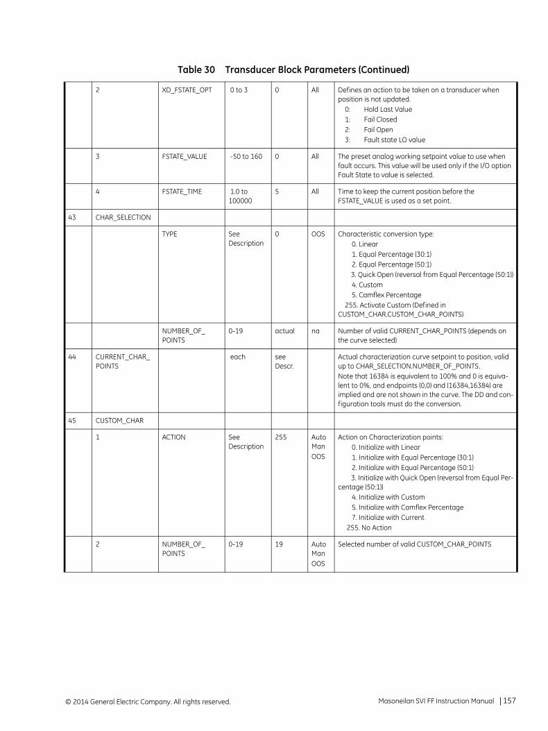
2 XD_FSTATE_OPT 0 to 3 0 All Defines an action to be taken on a transducer when position is not updated. 0: Hold Last Value 1: Fail Closed 2: Fail Open 3: Fault state LO value
3 FSTATE_VALUE -50 to 160 0 All The preset analog working setpoint value to use when fault occurs. This value will be used only if the I/O option Fault State to value is selected.
4 FSTATE_TIME 1.0 to 100000
5 All Time to keep the current position before the FSTATE_VALUE is used as a set point.
43 CHAR_SELECTION
TYPE See Description
0 OOS Characteristic conversion type: 0. Linear 1. Equal Percentage (30:1) 2. Equal Percentage (50:1) 3. Quick Open (reversal from Equal Percentage (50:1)) 4. Custom 5. Camflex Percentage 255. Activate Custom (Defined in CUSTOM_CHAR.CUSTOM_CHAR_POINTS)
NUMBER_OF_POINTS
0-19 actual na Number of valid CURRENT_CHAR_POINTS (depends on the curve selected)
44 CURRENT_CHAR_POINTS
each see Descr.
Actual characterization curve setpoint to position, valid up to CHAR_SELECTION.NUMBER_OF_POINTS.Note that 16384 is equivalent to 100% and 0 is equiva-lent to 0%, and endpoints (0,0) and (16384,16384) are implied and are not shown in the curve. The DD and con-figuration tools must do the conversion.
45 CUSTOM_CHAR
1 ACTION See Description
255 Auto ManOOS
Action on Characterization points: 0. Initialize with Linear 1. Initialize with Equal Percentage (30:1) 2. Initialize with Equal Percentage (50:1) 3. Initialize with Quick Open (reversal from Equal Per-centage (50:1)) 4. Initialize with Custom 5. Initialize with Camflex Percentage 7. Initialize with Current 255. No Action
2 NUMBER_OF_POINTS
0-19 19 Auto ManOOS
Selected number of valid CUSTOM_CHAR_POINTS
Table 30 Transducer Block Parameters (Continued)
Masoneilan SVI FF Instruction Manual =| 157© 2014 General Electric Company. All rights reserved.

46 CUSTOM_CHAR_POINTS
CUSTOM_CHAR_POINTS
each Auto ManOOS
Custom characterization points. The array contains x-y pairs in an increasing order. The slope of the curve should be limited between 2.5 and 87.5 degrees. (slope between 0.05 and 20) for up to selected CUSTOM_CHAR.NUMBER_OF_POINTS. If this condition is not true, the curve can be saved but cannot be activated (by writing CHAR_SELECTION.TYPE=4)The initial value is expected to be (if Camflex is selected):Setpoint (16 bit) Position (16 bit) 2458 983 4915 1966 7117 2949 8724 3932 9981 4915 11012 5898 11869 6881 12593 7864 13206 8847 13718 9830 14156 10813 14944 12780 15335 13763 15729 14746 16122 15729
16384 is equivalent to 100% and 0 is equivalent to 0%, and endpoints (0, 0) and (16384,16384) are implied and must not be entered in the curve. The DD and configura-tion tools must do the conversion.
47 READBACK_SELECT
0 Selects whether working position or final position value is passed back to connected function block.
0: Final Position Value. It is strongly recommended to keep 0 as the Final Position value.1: Working Position Value
This parameter only has impact on AO block.
48 TRANSDUCER_TYPE
100 100 Standard Pressure
49 XD_ERROR_PRESSURE
0 0 Pressure transducer error
50 SUPPLY_PRESSURE The actual valve supply pressure and status.
1 STATUS
2 VALUE
51 PRESSURE_RANGE Man, OOS
The range of the supply pressure.This parameter has to be synchronized with the scale parameter of the Analog Output block
1 EU_100 0-1034.2 1034.2 Upper Range for the supply pressure. The value should be recalculated if the Unit Index is changed. This value is not user changeable.
2 EU_0 0-1034.2 0 Lower Range for the supply pressure. This value is not user changeable.
Table 30 Transducer Block Parameters (Continued)
© 2014 General Electric Company. All rights reserved.158 | =GE Oil & Gas

3 UNITS_INDEX See Description
kPa (1133)
Engineering Units The following values should be avail-able:
1133: Kpa1141: psi1137: BAR
4 DECIMAL 3 3 3
52 SUPPLY_PRESSURE_HI_ALERT
1 PRESSURE Current SUPPLY_PRESSURE value
2 ALERT_POINT 0-1034.2 1034.2 SUPPLY_PRESSURE Value, above which the ALERT will be set to True. Should be in the units of pressure
3 DEADBAND 0 - 20 0.5 SUPPLY_PRESSURE change, required to clear the ALERT, once it was set to True
4 ALERT FALSE True if the SUPPLY_PRESSURE has reached above ALERT_POINT and have not come below (ALERT_POINT-DEADBAND)
5 HISTORIC ALERT True - False FALSE True if ALERT is trueNot Changed if ALERT is false
6 ENABLE True - False TRUE True - Enables the ALERT to be reported according to the configuration False - Disables ALERT reporting
53 SUPPLY_PRESSURE_LO_ALERT
1 PRESSURE Current SUPPLY_PRESSURE value
2 ALERT_POINT 0-1034.2 20 SUPPLY_PRESSURE Value, below which the ALERT will be set to True
3 DEADBAND 0 - 20 0.5 SUPPLY_PRESSURE change, required to clear the ALERT, once it was set to True
4 ALERT FALSE FALSE True if the SUPPLY_PRESSURE has reached below ALERT_POINT and have not come above (ALERT_POINT+DEADBAND)
5 HISTORIC ALERT True - False FALSE True if ALERT is trueNot Changed if ALERT is false
6 ENABLE True - False TRUE True - Enables the ALERT to be reported according to the configuration False - Disables ALERT reporting
54 SUPPLY_PRESSURE_LOLO_ALERT
1 PRESSURE Current SUPPLY_PRESSURE value
2 ALERT_POINT 0-1034.2 20 SUPPLY_PRESSURE Value, below which the ALERT will be set to True
3 DEADBAND 0 - 20 0.5 SUPPLY_PRESSURE change, required to clear the ALERT, once it was set to True
Table 30 Transducer Block Parameters (Continued)
Masoneilan SVI FF Instruction Manual =| 159© 2014 General Electric Company. All rights reserved.

4 ALERT FALSE FALSE True if the SUPPLY_PRESSURE has reached below ALERT_POINT and have not come above (ALERT_POINT+DEADBAND)
5 HISTORIC ALERT True - False FALSE True if ALERT is trueNot Changed if ALERT is false
6 ENABLE True - False TRUE True - Enables the ALERT to be reported according to the configuration False - Disables ALERT reporting
55 ACTUATOR_A_PRESSURE
The actual control pressure and status.
1 STATUS
2 VALUE
56 ACTUATOR_B_PRESSURE
The actual control pressure and status. Valid for double acting valves.
1 STATUS
2 VALUE
57 ATMOSPHERIC_PRESSURE
The actual Atmospheric pressure and status.
1 STATUS
2 VALUE
58 PILOT_PRESSURE The actual pilot pressure and status.
1 STATUS
2 VALUE
59 TEMP_TRANSDUCER_TYPE
101 101 Standard Temperature
60 XD_ERROR_TEMPERATURE
0 0 Temperature Transducer Error 22 I/O Failure
61 TEMPERATURE The actual temperature measured by actuator electronics.
1 STATUS
2 VALUE
62 TEMPERATURE_HI_ALERT
High temperature alert.
1 TEMPERATURE Current TEMPERATURE value
2 ALERT_POINT -45 to 85 85 TEMPERATURE Value, above which the ALERT will be set to True
3 DEADBAND 0 - 2 2 TEMPERATURE change, required to clear the ALERT, once it was set to True
4 ALERT FALSE True if the TEMPERATURE has reached above ALERT_POINT and have not come below (ALERT_POINT-DEADBAND)
Table 30 Transducer Block Parameters (Continued)
© 2014 General Electric Company. All rights reserved.160 | =GE Oil & Gas
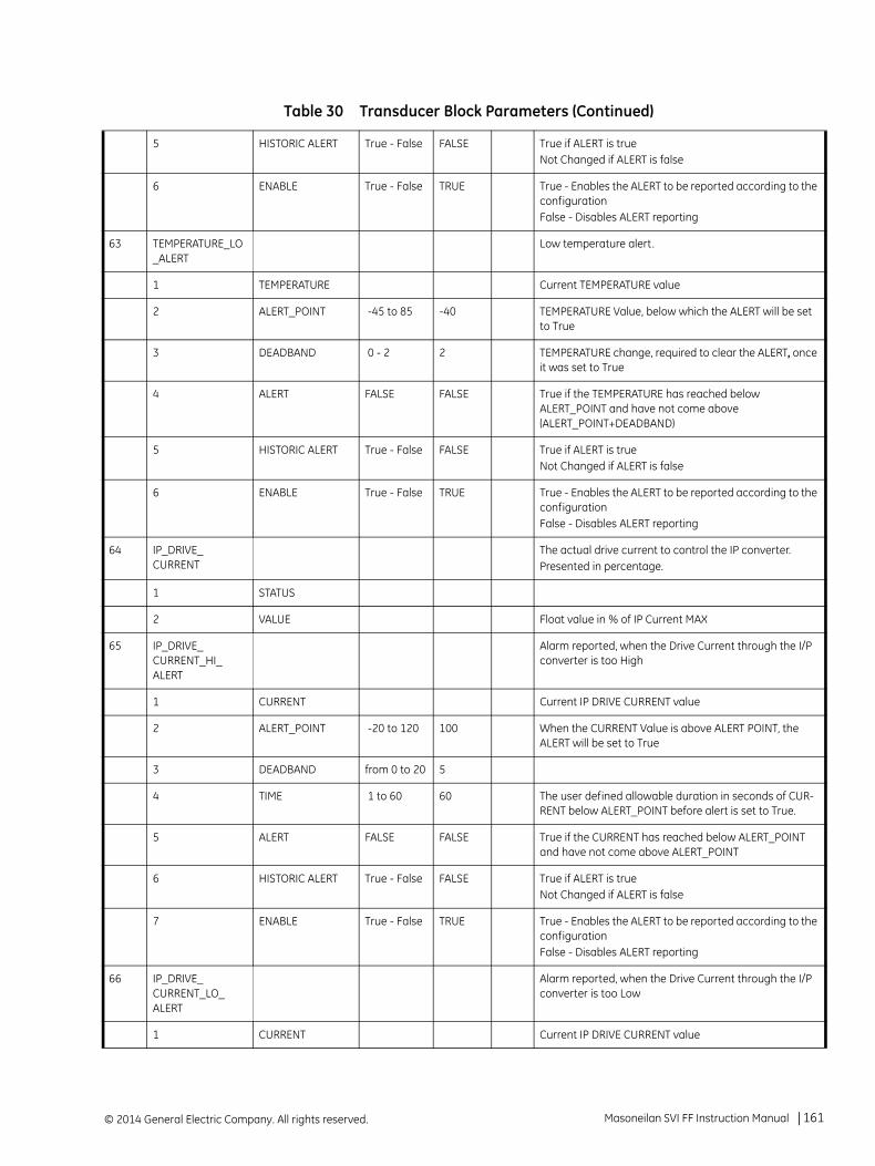
5 HISTORIC ALERT True - False FALSE True if ALERT is trueNot Changed if ALERT is false
6 ENABLE True - False TRUE True - Enables the ALERT to be reported according to the configuration False - Disables ALERT reporting
63 TEMPERATURE_LO_ALERT
Low temperature alert.
1 TEMPERATURE Current TEMPERATURE value
2 ALERT_POINT -45 to 85 -40 TEMPERATURE Value, below which the ALERT will be set to True
3 DEADBAND 0 - 2 2 TEMPERATURE change, required to clear the ALERT, once it was set to True
4 ALERT FALSE FALSE True if the TEMPERATURE has reached below ALERT_POINT and have not come above (ALERT_POINT+DEADBAND)
5 HISTORIC ALERT True - False FALSE True if ALERT is trueNot Changed if ALERT is false
6 ENABLE True - False TRUE True - Enables the ALERT to be reported according to the configuration False - Disables ALERT reporting
64 IP_DRIVE_CURRENT
The actual drive current to control the IP converter. Presented in percentage.
1 STATUS
2 VALUE Float value in % of IP Current MAX
65 IP_DRIVE_CURRENT_HI_ALERT
Alarm reported, when the Drive Current through the I/P converter is too High
1 CURRENT Current IP DRIVE CURRENT value
2 ALERT_POINT -20 to 120 100 When the CURRENT Value is above ALERT POINT, the ALERT will be set to True
3 DEADBAND from 0 to 20 5
4 TIME 1 to 60 60 The user defined allowable duration in seconds of CUR-RENT below ALERT_POINT before alert is set to True.
5 ALERT FALSE FALSE True if the CURRENT has reached below ALERT_POINT and have not come above ALERT_POINT
6 HISTORIC ALERT True - False FALSE True if ALERT is trueNot Changed if ALERT is false
7 ENABLE True - False TRUE True - Enables the ALERT to be reported according to the configuration False - Disables ALERT reporting
66 IP_DRIVE_CURRENT_LO_ALERT
Alarm reported, when the Drive Current through the I/P converter is too Low
1 CURRENT Current IP DRIVE CURRENT value
Table 30 Transducer Block Parameters (Continued)
Masoneilan SVI FF Instruction Manual =| 161© 2014 General Electric Company. All rights reserved.
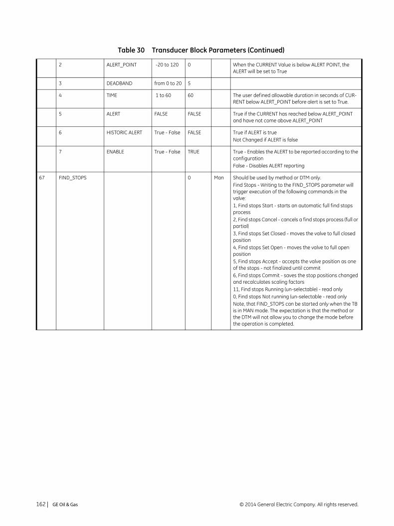
2 ALERT_POINT -20 to 120 0 When the CURRENT Value is below ALERT POINT, the ALERT will be set to True
3 DEADBAND from 0 to 20 5
4 TIME 1 to 60 60 The user defined allowable duration in seconds of CUR-RENT below ALERT_POINT before alert is set to True.
5 ALERT FALSE FALSE True if the CURRENT has reached below ALERT_POINT and have not come above ALERT_POINT
6 HISTORIC ALERT True - False FALSE True if ALERT is trueNot Changed if ALERT is false
7 ENABLE True - False TRUE True - Enables the ALERT to be reported according to the configuration False - Disables ALERT reporting
67 FIND_STOPS 0 Man Should be used by method or DTM only.Find Stops - Writing to the FIND_STOPS parameter will trigger execution of the following commands in the valve:1, Find stops Start - starts an automatic full find stops process2, Find stops Cancel - cancels a find stops process (full or partial)3, Find stops Set Closed - moves the valve to full closed position4, Find stops Set Open - moves the valve to full open position5, Find stops Accept - accepts the valve position as one of the stops - not finalized until commit6, Find stops Commit - saves the stop positions changed and recalculates scaling factors11, Find stops Running (un-selectable) - read only0, Find stops Not running (un-selectable - read onlyNote, that FIND_STOPS can be started only when the TB is in MAN mode. The expectation is that the method or the DTM will not allow you to change the mode before the operation is completed.
Table 30 Transducer Block Parameters (Continued)
© 2014 General Electric Company. All rights reserved.162 | =GE Oil & Gas

68 OFFLINE_DIAGNOSTIC
See Description
0 Man Should be used by method or DTM only.Offline valve diagnostic procedure command and status.Writing to this parameter will trigger the procedure to execute the following procedures: 1. Execute Valve Signature 2. Execute Ramp Test 3. Save current signature as Baseline 4. Save current signature as Custom 5. Save current signature as Current 6. Prepare Baseline for Upload 7. Prepare Custom for Upload 8. Prepare Current for Upload 9. Execute Step Test 10. Save current signature as Factory 99. Cancel DiagnosticThis parameter may be written only when the parameter DIAGNOSTIC_CONFIGURATION contains correct values of sub-parameters. It means that DIAGNOSTIC_CONFIGURATION must be written prior to OFFLINE_DIAGNOSTIC.
Reading this parameter will provide the status of the last OffLine Procedure 0.Not Running 100. Running
69 DIAGNOSTIC_CONFIGURATION
Should be used by method or DTM only.
1 START_POSITION
40 Any Applicable to: AllStart position for the test. May be above or below End positionRange is -5 to full open +5
2 END_POSITION 60 Any Applicable to: AllStart position for the test. May be above or below End positionRange is -5 to full open +5
Applicable to open loop signature: Start and End Posi-tions must be more than 20% different
3 SET_POINT_RATE
5 Any Applicable to: Ramp test and Signatures0.5-100.1 %/s
4 SAMPLING_TIME
10 Any Applicable to: Step test2 to 60 s.
5 DIRECTION 0 Any Applicable to: Diagnostic signature, Ramp test0. Both ways (from Start position to End position and back)1. One way (from Start position to End position)
6 OPTION 0 Any Applicable to: Diagnostic signature0. Open loop1. Closed loop
Table 30 Transducer Block Parameters (Continued)
Masoneilan SVI FF Instruction Manual =| 163© 2014 General Electric Company. All rights reserved.

70 DIAGNOSTIC_DATA See Description
0 Any Should be used by DTM only.An array that will contain the data collected during the diagnostic procedure execution.[0] - Contains the offset in bytes of the data to read from the beginning of the diagnostic data buffer, This is the only writable value in the array and may be used to initi-ate the read procedure, by writing 0. The value will be auto incremented after each read of the array with sub-index 0.[1] - skip count - writing 0 to this reads all of the data, writing 1 reads every other point, writing 2 reads every 3rd point, etc.[2] - number of valid data pairs read. A user program can read all of the data by making successive reads until this value is less than 12.[3] - [26] - Diagnostic Data chunk. It will contain data pairs (position/pressure pairs or position/setpoint pairs) as follows e.g.: [3]-1st position integer [4] - 1st Pressure integer [5]-2nd position integer [6] - 2nd Pressure integer ...Note that the first record of the buffer will have some information about the results to the procedure, includ-ing: - Procedure being executed - Configuration used for the procedure - number of data points - starting and ending position - other parameters specific to the testsee the UC25 document for details of the headers for various tests
71 AUTOTUNE Man Should be used by method or DTM only.Writing will set three parameters: Supply Pressure, Aggressiveness and Tune Flags and send their values the processor for updating.The fourth parameter Completion may take only one of three values on writing: DO nothing (0), START Auto-tune(1), CANCEL Autotune (99). All other values on write are rejected, and a wrong parameter error is reported.Reading will return values of the first three parameters obtained from the processor. The fourth parameter - Completion, on the read specifies the autotune process completion code.
Supply Press Supply Pressure
Aggressiveness -9 to 9 Aggressiveness of the Auto Tune Procedure: -9: Relaxed 0 Normal (Default) +9: Aggressive
Tune Flags 1 Not currently used
Table 30 Transducer Block Parameters (Continued)
© 2014 General Electric Company. All rights reserved.164 | =GE Oil & Gas
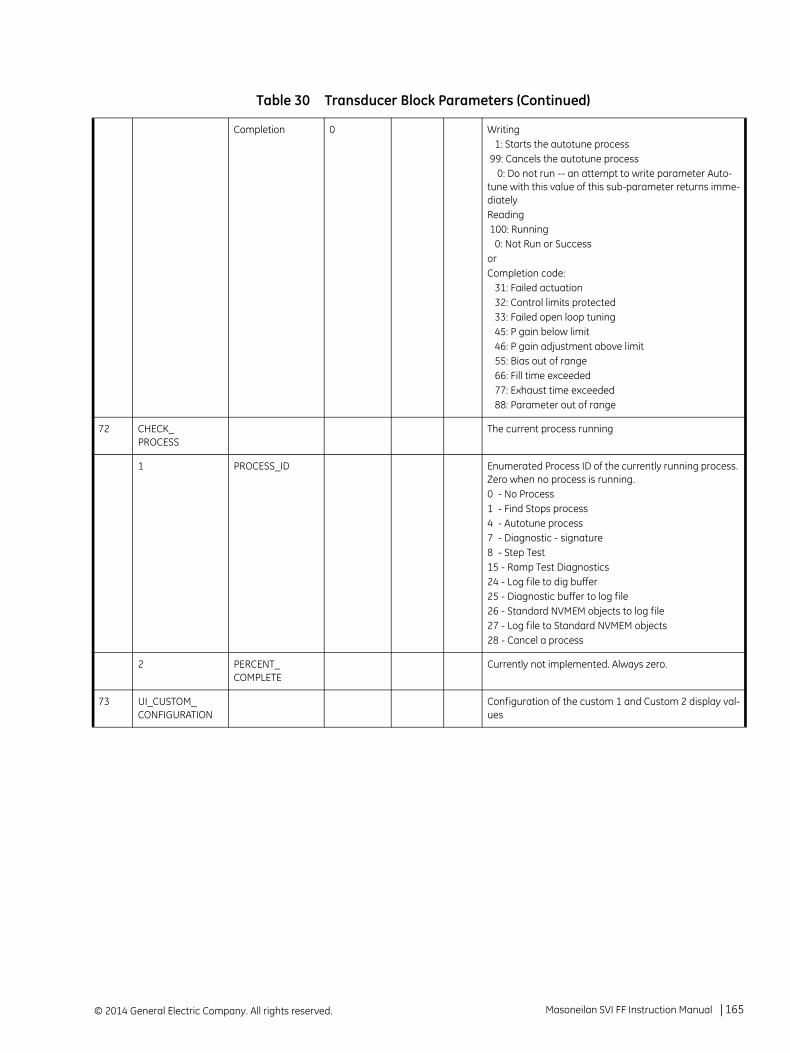
Completion 0 Writing 1: Starts the autotune process 99: Cancels the autotune process 0: Do not run -- an attempt to write parameter Auto-tune with this value of this sub-parameter returns imme-diatelyReading 100: Running 0: Not Run or Success orCompletion code: 31: Failed actuation 32: Control limits protected 33: Failed open loop tuning 45: P gain below limit 46: P gain adjustment above limit 55: Bias out of range 66: Fill time exceeded 77: Exhaust time exceeded 88: Parameter out of range
72 CHECK_PROCESS
The current process running
1 PROCESS_ID Enumerated Process ID of the currently running process. Zero when no process is running.0 - No Process1 - Find Stops process4 - Autotune process7 - Diagnostic - signature8 - Step Test15 - Ramp Test Diagnostics24 - Log file to dig buffer25 - Diagnostic buffer to log file26 - Standard NVMEM objects to log file27 - Log file to Standard NVMEM objects28 - Cancel a process
2 PERCENT_COMPLETE
Currently not implemented. Always zero.
73 UI_CUSTOM_CONFIGURATION
Configuration of the custom 1 and Custom 2 display val-ues
Table 30 Transducer Block Parameters (Continued)
Masoneilan SVI FF Instruction Manual =| 165© 2014 General Electric Company. All rights reserved.

1 CUSTOM_1_CONFIGURATION
from 1-9 1 Any Custom_1_Configuration will allow the user to select the value displayed on the local LCD display. The value is converted to the processor as an Integer and it will be used to generate a display string as follows: 1. WORK_SP (Default for the Custom 1). 2. WORK_POS 3. PID1.SP 4. PID1.PV 5. PID1.OUT 6. PID2.SP 7. PID2.PV 8. PID2.OUT 9. AI1.OUT 10. AI2.OUT 11. AI3.OUT 12. AO.SP 13. DO1.SP 14. DO2.SP 15. IS.IN1 16. IS.IN2 17. IS.IN3 18. IS.IN4
2 CUSTOM_2_CONFIGURATION
from 1-9 2 Any Custom_2_Configuration will allow the user to select the value displayed on the local LCD display for the second custom selection. The value is converted to the proces-sor as an Integer and it will be used to generate a display string as follows: 1. WORK_SP 2. WORK_POS. (Default for the Custom 2). 3. PID1.SP 4. PID1.PV 5. PID1.OUT 6. PID2.SP 7. PID2.PV 8. PID2.OUT 9. AI1.OUT 10. AI2.OUT 11. AI3.OUT 12. AO.SP 13. DO1.SP 14. DO2.SP 15. IS.IN1 16. IS.IN2 17. IS.IN3 18. IS.IN4
74 FAILED_STATE Failed State status
1 FF NA NA FF related failed State 1 - FAILED_STATE is reported by the Resource Block 0 - No FAILED STATE condition exists
2 APP Valve Control related Failed State 0 - No active Valve Control Failed State condition exists
1 - Failed State Condition is detected in the Valve Con-trol
Table 30 Transducer Block Parameters (Continued)
© 2014 General Electric Company. All rights reserved.166 | =GE Oil & Gas

3 PROPAGATE_APFS_TO_RB
0, 1 1 Propagate Fail State to Resource Block 0 – Do not propagate 1 – Propagate Failsafe state of TB to RB
75 FINAL_VALUE_D MAN OOS
Set Point Received from DO block as boolean. This Point shall be referred as Channel 2
1 STATUS BAD Status of the set point value
2 VALUE 0, 1 Value: 0 - Complete close #0 - Complete Open
76 FINAL_POSITION_VALUE_D
Actual discrete valve position, provided to DO block as boolean. This Point shall be referred as Channel 2.
1 STATUS BAD Status of the position value
2 VALUE 0, 1, 2,4,. . .100
Value: 0 - Complete close #0 - Partially or fully Open
77 FINAL_VALUE_DINT
MAN OOS
Set Point Received from DO block as integer. This Point shall be referred as Channel 3
1 STATUS BAD Status of the set point value
2 VALUE 0, 1, 2,4,. . .100
Value: 0 - Complete close 0 -100 - Discrete value of the setpoint in increments of %All other values will be rejected with a status - Out of Range
78 FINAL_POSITION_VALUE_DINT
Actual discrete valve position, provided to DO block as Integer. This Point shall be referred as Channel 3
1 STATUS BAD Status of the position value
2 VALUE 0, 1, 2,4,. . .100
Value: 0 - Complete close 1-100 - Discrete value of the setpoint in increments of %All other values will be rejected with a status - Out of Range
79 DISCRETE_OUTPUT_1
Discrete Switch Output 1 value and status
1 STATUS Status
2 VALUE 0,1 Value: 0 - Close 1 - Open
80 DISCRETE_OUTPUT_2
Discrete Switch Output 2 value and status.Virtual switch.
1 STATUS Status
2 VALUE 0,1 Value: 0 - Close 1 - Open
Table 30 Transducer Block Parameters (Continued)
Masoneilan SVI FF Instruction Manual =| 167© 2014 General Electric Company. All rights reserved.
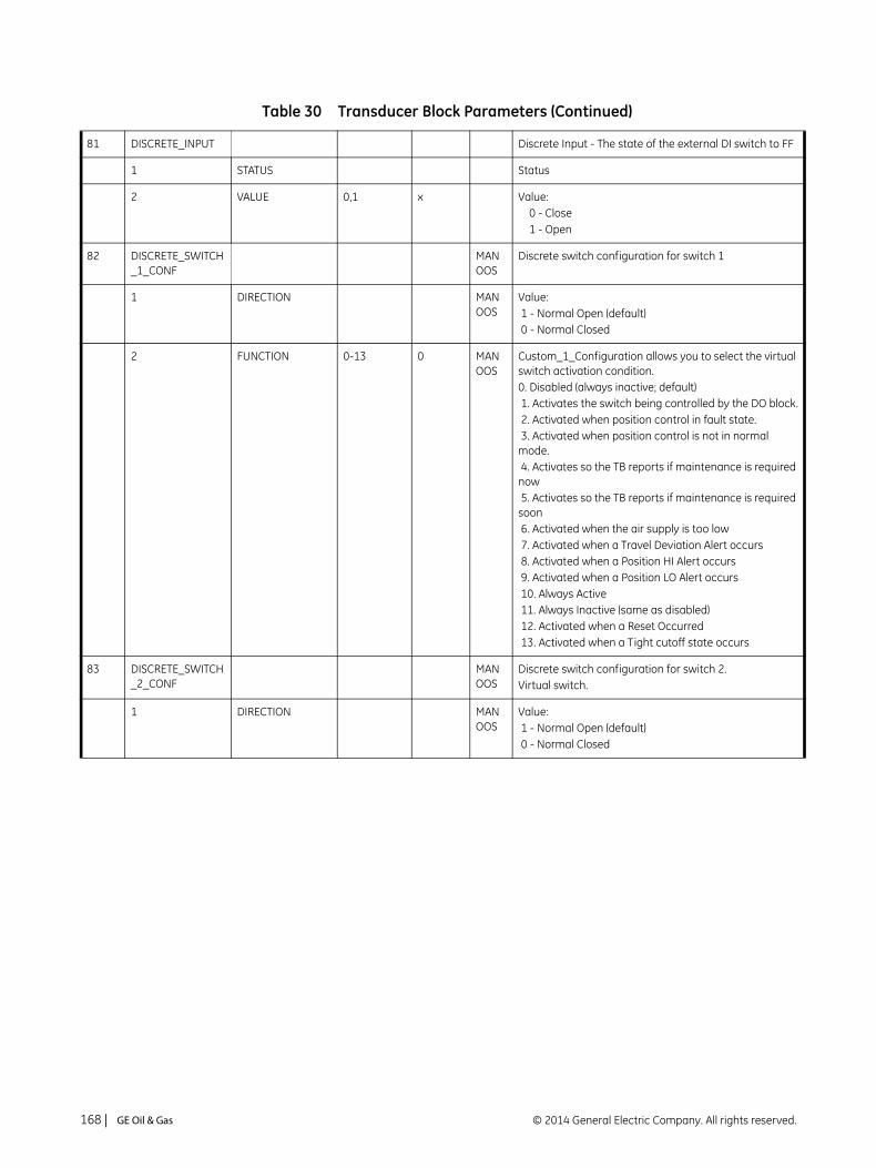
81 DISCRETE_INPUT Discrete Input - The state of the external DI switch to FF
1 STATUS Status
2 VALUE 0,1 x Value: 0 - Close 1 - Open
82 DISCRETE_SWITCH_1_CONF
MAN OOS
Discrete switch configuration for switch 1
1 DIRECTION MAN OOS
Value: 1 - Normal Open (default) 0 - Normal Closed
2 FUNCTION 0-13 0 MAN OOS
Custom_1_Configuration allows you to select the virtual switch activation condition.0. Disabled (always inactive; default) 1. Activates the switch being controlled by the DO block. 2. Activated when position control in fault state. 3. Activated when position control is not in normal mode. 4. Activates so the TB reports if maintenance is required now 5. Activates so the TB reports if maintenance is required soon 6. Activated when the air supply is too low 7. Activated when a Travel Deviation Alert occurs 8. Activated when a Position HI Alert occurs 9. Activated when a Position LO Alert occurs 10. Always Active 11. Always Inactive (same as disabled) 12. Activated when a Reset Occurred 13. Activated when a Tight cutoff state occurs
83 DISCRETE_SWITCH_2_CONF
MAN OOS
Discrete switch configuration for switch 2.Virtual switch.
1 DIRECTION MAN OOS
Value: 1 - Normal Open (default) 0 - Normal Closed
Table 30 Transducer Block Parameters (Continued)
© 2014 General Electric Company. All rights reserved.168 | =GE Oil & Gas

2 FUNCTION 0-13 0 MAN OOS
Custom_2_Configuration allows you to select the virtual switch activation condition.0. Disabled (always inactive; default) 1. Activates the switch being controlled by the DO block. 2. Activated when position control in fault state. 3. Activated when position control is not in normal mode.4. Activates so the TB reports if maintenance is required now 5. Activates so the TB reports if maintenance is required soon6. Activated when the air supply is too low 7. Activated when a Travel Deviation Alert occurs 8. Activated when a Position HI Alert occurs 9. Activated when a Position LO Alert occurs 10. Always Active 11. Always Inactive (same as disabled) 12. Activated when a Reset Occurred 13. Activated when a Tight cutoff state occurs
84 UI_ACCESS_CONTROL
MAN/OOS
Controls the access and functions available to the LCD user interface display.
1 LOCK_LEVEL 0 MAN/OOS
2 PASSWORD_ENABLED
T/F F MAN/OOS
3 PASSWORD MAN/OOS
85 UI_LANGUAGE 0 to 6 0 -English
Man/OOS
0: English1: French2: Spanish3: Portuguese4: Japanese5: Italian6: German
86 APP_MODE Normal, Manual, LO, FailSafe
Normal Processor Mode
87 COMPLETE_STATUS
NA NA Full status presentation - Data is mapped to the Status presented in the processor. Fault matrix.
88 CLEAR_STATUS NA NA Clear status and faults:0 - No Action1 - Clear Current Status2 - Clear Current and Historic Status
89 OPEN_STOP_ADJUSTMENT
60.00 to 100.00
Man, OOS
Keep set at 100%
90 SETPOINT_SOURCE
1 to 3 1 OOS Describes the source of the set point: 1 - Control is coming from AO-FINAL_VALUE 2 - Control is coming from DO-FINAL_VALUE_D in Open/Close mode 3 - Control is coming from DO-FINAL_VALUE_DINT in 1% steps mode
Table 30 Transducer Block Parameters (Continued)
Masoneilan SVI FF Instruction Manual =| 169© 2014 General Electric Company. All rights reserved.

91 SETPOINT Setpoint being transferred to the setpoint position.
1 STATUS GOOD Status
2 VALUE -50, 199 Value: Floating value representing the actual position
92 ACTUAL_POSITION Actual Position
1 STATUS Status
2 VALUE -50, 199 Value: Floating value presenting the actual position.
93 RAW_POSITION 0 Temperature compensated Raw Position Sensor value; in counts. The value should be between =/- 15000 for the valve to operate normally.
94 ALERT_ACTION
1 MAPPED_TO_RB See Description
Any Indicate if alarms will be reported by the RB: 1: Map to RB (Default) 2: Report in TB
2 Deviation Alert 0 - 3 2 Any The user shall be able to select one of the following: 0: Not Reported 1: Warning Data 2: Maintenance Required 3: Device Failure
3 Position HIHI Alert 0 - 3 2 Any Defines the action for a HIHI alert.
4 Position HI Alert 0 - 3 1 Any Defines the action for a HI alert.
5 Position LO Alert 0 - 3 1 Any Defines the action for a LO alert.
6 Position LOLO Alert 0 - 3 2 Any Defines the action for a LOLO alert.
7 Set Point Timeout Alert
0 - 3 2 Any Defines the action for a Set Point Timeout alert.
8 Near Close Alert 0 - 3 1 Any Defines the action for a Near Close alert.
9 Travel Accumulation A Alert
0 - 3 1 Any Defines the action for a Travel Accumulation alert.
10 Travel Accumulation B Alert
0 - 3 1 Any Defines the action for a Travel Accumulation alert.
11 Cycle Counter A Alert
0 - 3 2 Any Defines the action for a Cycle Counter alert.
12 Cycle Counter B Alert
0 - 3 2 Any Defines the action for a Cycle Counter alert.
13 Working Time Alert
0 - 3 1 Any Defines the action for a Working Time alert.
14 Supply Pressure HI Alert
0 - 3 2 Any Defines the action for a Supply Pressure HI alert.
15 Supply Pressure LO Alert
0 - 3 1 Any Defines the action for a Supply Pressure LO alert.
16 Supply Pressure LOLO Alert
0 - 3 2 Any Defines the action for a Supply Pressure LOLO alert.
Table 30 Transducer Block Parameters (Continued)
© 2014 General Electric Company. All rights reserved.170 | =GE Oil & Gas

17 Temperature HI Alert
0 - 3 1 Any Defines the action for a Temperature HI alert.
18 Temperature LO Alert
0 - 3 1 Any Defines the action for a Temperature LO alert.
19 IP Drive Current Alert HI
0 - 3 2 Any Defines the action for a IP Drive Current HI alert.
20 IP Drive Current Alert LO
0 - 3 2 Any Defines the action for a IP Drive Current LO alert.
21 Sensor Failure Alert
0 - 3 3 Any Defines the action for a Sensor Failure alert.
22 Processor Alert 0 - 3 3 Any Defines the action for a Processor alert.
23 Valve Control Alert 0 - 3 3 Any Defines the action for a Valve Control alert .
24 Commissioning Alert
0 - 3 1 Any Defines the action for a Commissioning alert.
25 Air Supply Alert 0 - 3 1 Any Defines the action for a Air Supply alert.
26 Supporting Hardware Alert
0 - 3 1 Any Defines the action for a Supporting Hardware alert.
95 ALERT_STATE
1 Deviation Alert T/F F Any Provides the current state of the Alert condition: TRUE: Alert condition is active FALSE: Alert condition does not exist
2 Position HIHI Alert T/F F Any Provides the current state of the Position HIHI alert con-dition.
3 Position HI Alert T/F F Any Provides the current state of the Position HI alert condi-tion.
4 Position LO Alert T/F F Any Provides the current state of the Position LO alert condi-tion.
5 Position LOLO Alert T/F F Any Provides the current state of the Position LOLO alert con-dition.
6 Set Point Timeout Alert
T/F F Any Provides the current state of the Set Point Timeout alert condition.
7 Near Close Alert T/F F Any Provides the current state of the Near Close alert condi-tion.
8 Travel Accumulation A Alert
T/F F Any Provides the current state of the Travel Accumulation A alert condition.
9 Travel Accumulation B Alert
T/F F Any Provides the current state of the Travel Accumulation B alert condition.
10 Cycle Counter A Alert
T/F F Any Provides the current state of the Cycle Counter A alert condition.
11 Cycle Counter B Alert
T/F F Any Provides the current state of the Cycle Counter B alert condition.
Table 30 Transducer Block Parameters (Continued)
Masoneilan SVI FF Instruction Manual =| 171© 2014 General Electric Company. All rights reserved.
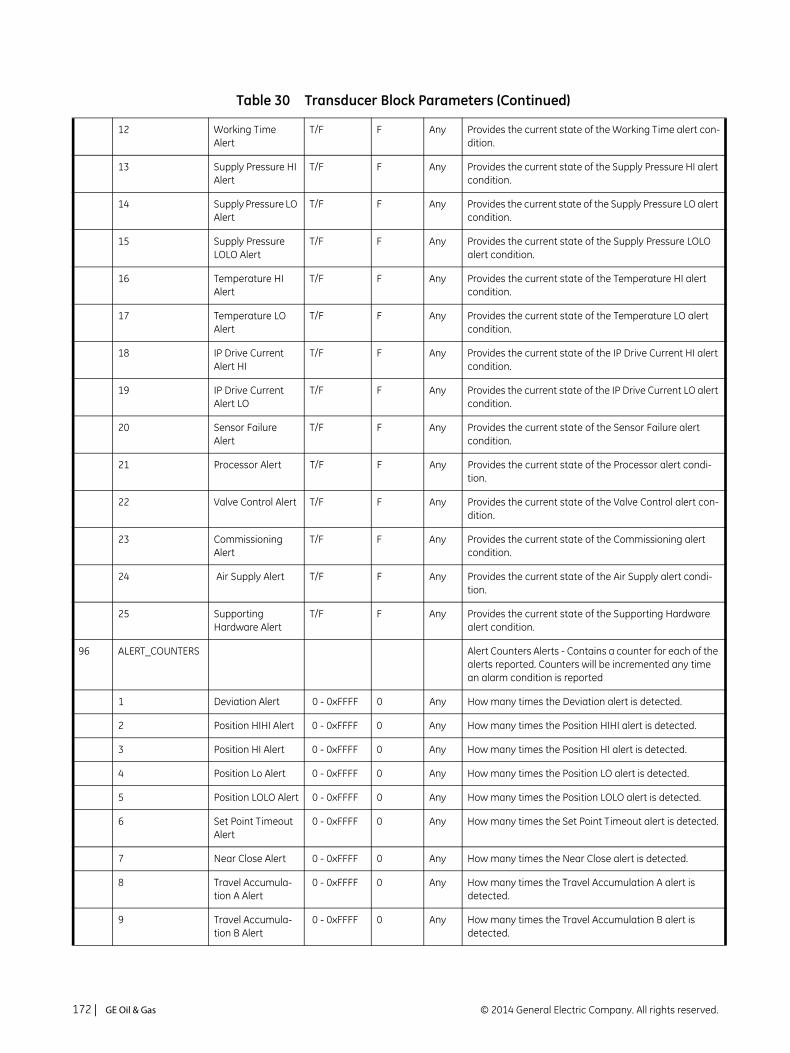
12 Working Time Alert
T/F F Any Provides the current state of the Working Time alert con-dition.
13 Supply Pressure HI Alert
T/F F Any Provides the current state of the Supply Pressure HI alert condition.
14 Supply Pressure LO Alert
T/F F Any Provides the current state of the Supply Pressure LO alert condition.
15 Supply Pressure LOLO Alert
T/F F Any Provides the current state of the Supply Pressure LOLO alert condition.
16 Temperature HI Alert
T/F F Any Provides the current state of the Temperature HI alert condition.
17 Temperature LO Alert
T/F F Any Provides the current state of the Temperature LO alert condition.
18 IP Drive Current Alert HI
T/F F Any Provides the current state of the IP Drive Current HI alert condition.
19 IP Drive Current Alert LO
T/F F Any Provides the current state of the IP Drive Current LO alert condition.
20 Sensor Failure Alert
T/F F Any Provides the current state of the Sensor Failure alert condition.
21 Processor Alert T/F F Any Provides the current state of the Processor alert condi-tion.
22 Valve Control Alert T/F F Any Provides the current state of the Valve Control alert con-dition.
23 Commissioning Alert
T/F F Any Provides the current state of the Commissioning alert condition.
24 Air Supply Alert T/F F Any Provides the current state of the Air Supply alert condi-tion.
25 Supporting Hardware Alert
T/F F Any Provides the current state of the Supporting Hardware alert condition.
96 ALERT_COUNTERS Alert Counters Alerts - Contains a counter for each of the alerts reported. Counters will be incremented any time an alarm condition is reported
1 Deviation Alert 0 - 0xFFFF 0 Any How many times the Deviation alert is detected.
2 Position HIHI Alert 0 - 0xFFFF 0 Any How many times the Position HIHI alert is detected.
3 Position HI Alert 0 - 0xFFFF 0 Any How many times the Position HI alert is detected.
4 Position Lo Alert 0 - 0xFFFF 0 Any How many times the Position LO alert is detected.
5 Position LOLO Alert 0 - 0xFFFF 0 Any How many times the Position LOLO alert is detected.
6 Set Point Timeout Alert
0 - 0xFFFF 0 Any How many times the Set Point Timeout alert is detected.
7 Near Close Alert 0 - 0xFFFF 0 Any How many times the Near Close alert is detected.
8 Travel Accumula-tion A Alert
0 - 0xFFFF 0 Any How many times the Travel Accumulation A alert is detected.
9 Travel Accumula-tion B Alert
0 - 0xFFFF 0 Any How many times the Travel Accumulation B alert is detected.
Table 30 Transducer Block Parameters (Continued)
© 2014 General Electric Company. All rights reserved.172 | =GE Oil & Gas
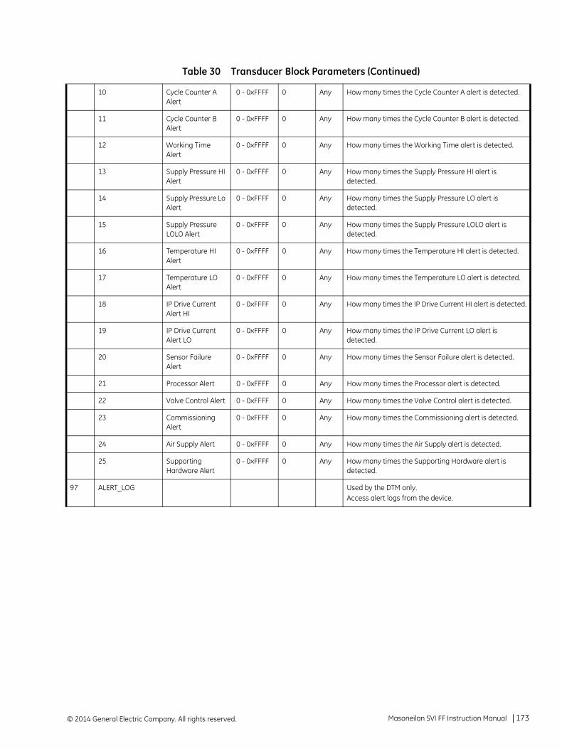
10 Cycle Counter A Alert
0 - 0xFFFF 0 Any How many times the Cycle Counter A alert is detected.
11 Cycle Counter B Alert
0 - 0xFFFF 0 Any How many times the Cycle Counter B alert is detected.
12 Working Time Alert
0 - 0xFFFF 0 Any How many times the Working Time alert is detected.
13 Supply Pressure HI Alert
0 - 0xFFFF 0 Any How many times the Supply Pressure HI alert is detected.
14 Supply Pressure Lo Alert
0 - 0xFFFF 0 Any How many times the Supply Pressure LO alert is detected.
15 Supply Pressure LOLO Alert
0 - 0xFFFF 0 Any How many times the Supply Pressure LOLO alert is detected.
16 Temperature HI Alert
0 - 0xFFFF 0 Any How many times the Temperature HI alert is detected.
17 Temperature LO Alert
0 - 0xFFFF 0 Any How many times the Temperature LO alert is detected.
18 IP Drive Current Alert HI
0 - 0xFFFF 0 Any How many times the IP Drive Current HI alert is detected.
19 IP Drive Current Alert LO
0 - 0xFFFF 0 Any How many times the IP Drive Current LO alert is detected.
20 Sensor Failure Alert
0 - 0xFFFF 0 Any How many times the Sensor Failure alert is detected.
21 Processor Alert 0 - 0xFFFF 0 Any How many times the Processor alert is detected.
22 Valve Control Alert 0 - 0xFFFF 0 Any How many times the Valve Control alert is detected.
23 Commissioning Alert
0 - 0xFFFF 0 Any How many times the Commissioning alert is detected.
24 Air Supply Alert 0 - 0xFFFF 0 Any How many times the Air Supply alert is detected.
25 Supporting Hardware Alert
0 - 0xFFFF 0 Any How many times the Supporting Hardware alert is detected.
97 ALERT_LOG Used by the DTM only.Access alert logs from the device.
Table 30 Transducer Block Parameters (Continued)
Masoneilan SVI FF Instruction Manual =| 173© 2014 General Electric Company. All rights reserved.

1 COMMAND Command (Write) / Status (Read). The Value written to this field forces the Alert Log API to execute the following functions; note, that for WRITE operations this field is interpreted as a Command.0x00 – Copy the Alert Log into the READ Buffer and Reset the read index on READ access. When the Read Alert Log parameter is then executed the Alert Log Entry if popu-lated with the first Alert Log array entry. The subsequent READ operations will populate the Alert Log Entry with the next entry, and so forth. The Command / Status field will return the number of entries in the Alert Log.0xFA – Writing this value will clear the AlertLog Table completely, including the NVRAMstorage.On READ oper-ation returns the number of Alert Log Entries, if the data read is valid; or returns 0 if the data entry is NOT valid.
Note: during READ operation the Command / Status field is Status. It contains the number of the Alert entries in the Alert Log. 0 - indicates No Entries. MAX number of Alert entries in the Alert Log is 32.
2 ALERT_TIME The Time stamp for the entry. When the data is cleared and there are no entries, this field shall be set as 0x00 00 00 00 00 00 0000.The same field is used when the alerts are reported to time stamp the alerts.
3 ALERT_DATA The Alert Bitmap. Contains the current state of all alerts. To see the alert, the Data value has to be compared with the previous data value. Will be updated when the alert is detected (a bit is set) and when the alert is cleared (a bit is cleared).
98 WORKING TIMES
1 SINCE_RESET Hours since last reset
2 TOTAL_TIME Lifetime Hours.
99 WORKING_TIME_ALERT
1 ALERT_TOTAL_TIME
Total Number of hours since manufacturing or since reset
2 ALERT_POINT <0xFFFFFFFF
8760 TOTAL_TIME Value, above which the ALERT will be set to True
3 ALERT FALSE FALSE TRUE if TOTAL TIME is higher than Alert Point
4 HISTORIC ALERT True - False FALSE True if ALERT is trueNot Changed if ALERT is false
5 ENABLE True - False 1 True - Enables the ALERT to be reported according to the configuration False - Disables ALERT reporting
100 FACTORY_USE_1 A parameter used for factory configuration of the instru-ment.
101 FACTORY_USE_2 A parameter used for factory configuration of the instru-ment.
Table 30 Transducer Block Parameters (Continued)
© 2014 General Electric Company. All rights reserved.174 | =GE Oil & Gas

102 ACTUATOR_1 Auto, Man, OOS
Information about the Actuator
1 ACT_MAN_ID The actuator manufacturer identification.
2 ACT_MODEL_NUM The actuator model number.
3 ACT_SN The actuator serial number.
103 ACTUATOR_2 Auto, Man, OOS
Information about the Actuator
1 ACT_TYPE Actuator Type. Default value shall be Spring-diaphragm
ACT_SIZE 6
ACT_ROTARY_MOMENT_ARM
n/a
ACT_EFFECTIVE_AREA
60
104 ACTUATOR_3 Auto, Man, OOS
Information about the Actuator
1 Shutoff_DP NA 100
2 Hand_Wheel NA -
3 STYLE See Description
1 The actuator Style0: Double Acting1: Single Acting
4 ACT_FAIL_ACTION See DescriptionLimit is important.
1 OOS Condition of the actuator, when the power is lost: 1. Valve Closed - Self-closing (air to open) 2. Valve Open - Self-opening (air to close)
5 RELAY_TYPE See DescriptionRange is not important
1 Auto, Man, OOS
Relay Type: 1.= Standard Relay: Double or Single Acting 2=High Capacity: Single Acting
6 SUPPLY_PRS_MAX NA Maximum Supply pressure for the Actuator
7 PRS_CONTROL_HI NA 103.4 Maximum Supply Pressure for the actuator in control - it should be the same as Bench Range?
8 PRS_CONTROL_LO NA 20.6 Minimum Supply Pressure for the actuator in control - it should be the same as Bench Range
105 ACTUATOR_INFO Auto, Man, OOS
1 DESCRIPTOR
2 MESSAGE
3 DATE
Table 30 Transducer Block Parameters (Continued)
Masoneilan SVI FF Instruction Manual =| 175© 2014 General Electric Company. All rights reserved.

4 SPEC_SHEET
106 VALVE_IDENTIFICATION
Auto, Man, OOS
Information about the Valve Identification
VALVE_MAN_ID The valve manufacturer identification.
VALVE_MODEL_NUM
The valve model number.
VALVE_SN The valve serial number
107 VALVE_SERVICE Valve Service information
SERVICE Water
PID_No
108 VALVE_BODY_1 Auto, Man, OOS
Valve Service information
VALVE_TYPE 1 The type of the valve. Globe, ReciprocatingValve Type – Description 0 Undefined 1 Linear 2 Rotary 255 OtherFISHER: Supports only: 1 Sliding-stem 2 Rotary
BODY SIZE Body Size
PACKING String containing the packing - Braided PTFE/Carbon or aramid core
PLUG_TYPE Linear Contoured
SEAT_RING_TYPE String containing the ring type - Quick Change
109 VALVE_BODY_2 Auto, Man, OOS
Valve Service information
CHARACTERISTIC
LEAKAGE_CLASS
110 VALVE_BODY_3 Auto, Man, OOS
Valve Service information
FLOW_ACTION
RATED_ADJ_CV
111 VALVE_INFO Auto, Man, OOS
Table 30 Transducer Block Parameters (Continued)
© 2014 General Electric Company. All rights reserved.176 | =GE Oil & Gas

1 SAME_AS_ACTUATOR
T/F T True if the valve and Actuator information is the same
1 DESCRIPTOR
2 MESSAGE
3 DATE
4 SPEC_SHEET
112 BOOSTER Auto, Man, OOS
Manufacturer
Model
Qty
113 ACCESSORY Auto, Man, OOS
SOLENOID
REMOTE_SENSOR 0-1 read2-3 write
0 Indicates/Enables the remote sensor connection. The following enumeration is available: 0: Remote sensor is disabled/Not Active (read only - write will do nothing) 1: Remote sensor is enabled (read only - write will do nothing) 2: Enable Local HAL Sensor (write only - write will do nothing if it is already 0) 3: Enable Remote Sensor (write only - write will do nothing if it is already 1)MUST restart device for the change to take effect
114 POSITION_EXTREMES
Auto, Man, OOS
Minimum and Maximum position values observed since start or the last update from the user
1 FINAL_VALUE_MAX -50 to 199 -50 FINAL VALUE: Maximum value detected since last update from the user.
2 FINAL_VALUE_MIN -50 to 199 199 FINAL VALUE: Minimum value detected since last update from the user.
3 FINAL_POS_VALUE_MAX
-50 to 199 -50 FINAL POSITION VALUE: Maximum value detected since last update from the user.
4 FINAL_POS_VALUE_MIN
-50 to 199 199 FINAL POSITION VALUE: Minimum value detected since last update from the user.
5 WORKING_SP_MAX
-50 to 199 -50 WORKING_SP: Maximum value detected since last update from the user.
6 WORKING_SP_MIN -50 to 199 199 WORKING_SP: Minimum value detected since last update from the user.
7 WORKING_POS_MAX
-50 to 199 -50 WORKING_POS: Maximum value detected since last update from the user.
Table 30 Transducer Block Parameters (Continued)
Masoneilan SVI FF Instruction Manual =| 177© 2014 General Electric Company. All rights reserved.
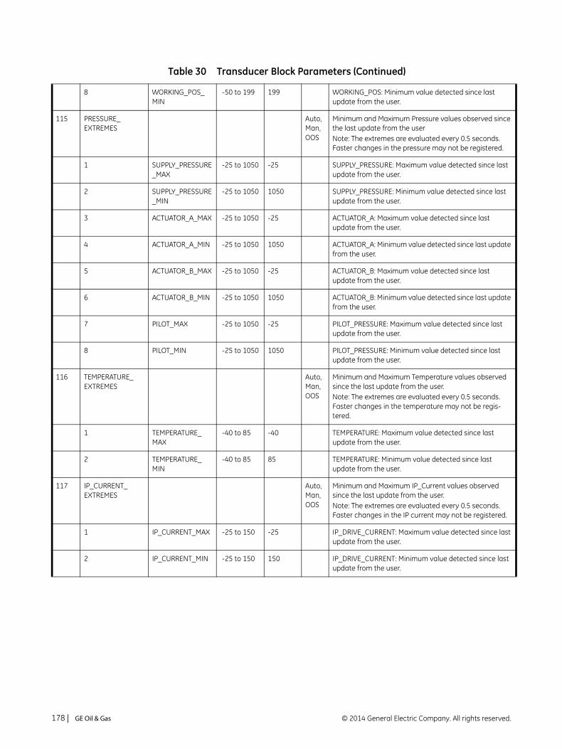
8 WORKING_POS_MIN
-50 to 199 199 WORKING_POS: Minimum value detected since last update from the user.
115 PRESSURE_EXTREMES
Auto, Man, OOS
Minimum and Maximum Pressure values observed since the last update from the userNote: The extremes are evaluated every 0.5 seconds. Faster changes in the pressure may not be registered.
1 SUPPLY_PRESSURE_MAX
-25 to 1050 -25 SUPPLY_PRESSURE: Maximum value detected since last update from the user.
2 SUPPLY_PRESSURE_MIN
-25 to 1050 1050 SUPPLY_PRESSURE: Minimum value detected since last update from the user.
3 ACTUATOR_A_MAX -25 to 1050 -25 ACTUATOR_A: Maximum value detected since last update from the user.
4 ACTUATOR_A_MIN -25 to 1050 1050 ACTUATOR_A: Minimum value detected since last update from the user.
5 ACTUATOR_B_MAX -25 to 1050 -25 ACTUATOR_B: Maximum value detected since last update from the user.
6 ACTUATOR_B_MIN -25 to 1050 1050 ACTUATOR_B: Minimum value detected since last update from the user.
7 PILOT_MAX -25 to 1050 -25 PILOT_PRESSURE: Maximum value detected since last update from the user.
8 PILOT_MIN -25 to 1050 1050 PILOT_PRESSURE: Minimum value detected since last update from the user.
116 TEMPERATURE_EXTREMES
Auto, Man, OOS
Minimum and Maximum Temperature values observed since the last update from the user.Note: The extremes are evaluated every 0.5 seconds. Faster changes in the temperature may not be regis-tered.
1 TEMPERATURE_MAX
-40 to 85 -40 TEMPERATURE: Maximum value detected since last update from the user.
2 TEMPERATURE_MIN
-40 to 85 85 TEMPERATURE: Minimum value detected since last update from the user.
117 IP_CURRENT_EXTREMES
Auto, Man, OOS
Minimum and Maximum IP_Current values observed since the last update from the user.Note: The extremes are evaluated every 0.5 seconds. Faster changes in the IP current may not be registered.
1 IP_CURRENT_MAX -25 to 150 -25 IP_DRIVE_CURRENT: Maximum value detected since last update from the user.
2 IP_CURRENT_MIN -25 to 150 150 IP_DRIVE_CURRENT: Minimum value detected since last update from the user.
Table 30 Transducer Block Parameters (Continued)
© 2014 General Electric Company. All rights reserved.178 | =GE Oil & Gas

118 ADVANCED Any Advanced/Standard implementation for the device
119 BLOCK_ERR_DESC_1
Bit map; bit N = 0 - No error, bit N = 1 - Specific error occurred.Bit 0: No Error. Reserved. Must be always 0.Bit 1: Mode Switch Error. 1 = The PTB Actual mode cannot be set to any non-AUTO mode.Bit 2: The response to the FF request times out.Bit 3: SP Source conflict. 1 = A DO block attempts to become a SP source on the channel already taken by the other DO block.Bit 4: FIND_STOPS Failed. 1 = Find Stops request made by writing FIND_STOPS parameter failed.
Table 30 Transducer Block Parameters (Continued)
Masoneilan SVI FF Instruction Manual =| 179© 2014 General Electric Company. All rights reserved.

This page intentionally left blank.
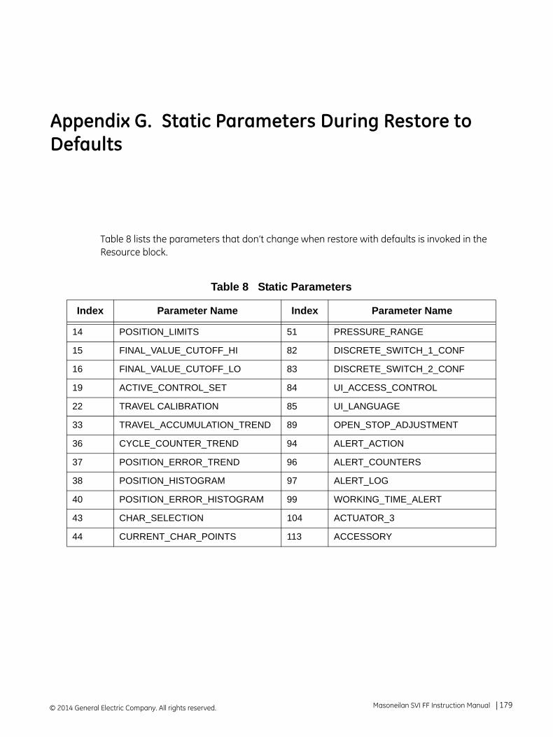
Appendix G. Static Parameters During Restore to Defaults
Table 8 lists the parameters that don’t change when restore with defaults is invoked in the Resource block.
Table 8 Static Parameters
Index Parameter Name Index Parameter Name
14 POSITION_LIMITS 51 PRESSURE_RANGE
15 FINAL_VALUE_CUTOFF_HI 82 DISCRETE_SWITCH_1_CONF
16 FINAL_VALUE_CUTOFF_LO 83 DISCRETE_SWITCH_2_CONF
19 ACTIVE_CONTROL_SET 84 UI_ACCESS_CONTROL
22 TRAVEL CALIBRATION 85 UI_LANGUAGE
33 TRAVEL_ACCUMULATION_TREND 89 OPEN_STOP_ADJUSTMENT
36 CYCLE_COUNTER_TREND 94 ALERT_ACTION
37 POSITION_ERROR_TREND 96 ALERT_COUNTERS
38 POSITION_HISTOGRAM 97 ALERT_LOG
40 POSITION_ERROR_HISTOGRAM 99 WORKING_TIME_ALERT
43 CHAR_SELECTION 104 ACTUATOR_3
44 CURRENT_CHAR_POINTS 113 ACCESSORY
© 2014 General Electric Company. All rights reserved. Masoneilan SVI FF Instruction Manual =| 179

This page intentionally left blank.

Appendix H. Notes on Characterization
Valve Over/Under Reaction Near Endpoints
This section is intended to explain why at times the valve can appear to be either over-reacting or under-reacting to the user-based configuration.
A principle point to understand is the difference between the travel domain and the user domain:
The travel domain is what is actually happening to the valve - the amount of movement during operation. This reflects the state of the working setpoint .
The user domain is reflected in the output seen on the LCD, through a DTM or other interface. This reflects the value of the FINAL_VALUE parameter.
How do these two relate to each other:
FINAL_VALUE --> Characterization process --> Working Setpoint
Whichever user-selected characterization process occurs (based on valve type), dictates the behavior that are seen during valve operation. Figure 60 shows the characterizations curves.
Figure 60 Characterization Curves
© 2014 General Electric Company. All rights reserved. Masoneilan SVI FF Instruction Manual =| 181

An example to highlight the difference between the travel and user domains, is the effect of FINAL_VALUE_CUTOFF_HI, a user-configurable parameter, on the Quick Open and EQ% 50 curves. The Quick Open curve has a much more dramatic increase/decrease near the curve extremes than the EQ% 50. For the Quick Open curve, if you a enter a FINAL_VALUE_CUTOFF_HI value, it causes a large deviation between the working setpoint (travel domain and the FINAL_VALUE (user domain) (see the red arrows in Figure 60). Entering the same FINAL_VALUE_CUTOFF_HI value for the EQ% 50 causes a much smaller deviation.
If you were to do the same for both curves using the FINAL_VALUE_CUTOFF_LO value the effects would swap.
Configuration of Position Limits, Position Rate Limits and FINAL_VALUE_CUTOFF and Characterization
Figure 61 graphically explains how setpoint and position interact.
Figure 61 ValVue SVIFF Setpoint to Position Schema
Figure 62 shows the interplay between a configured position limit, in this case 10% and its effect for two characterization types:
For Linear (red curve), the 10% limit causes an effective setpoint limit of 10%.
For EQ% 50 (green curve with triangles), the 10% limit causes an effective limit of 45%.
This type of behavior must be kept in mind when choosing a characterization and associated limits.
Final Value
Final Value.d
Final Value.dint
Setpointsource
Characterization
Reverse Characterization
Final Position Value
Final Position Value.d
Final Position Value.dint
Actualposition
Working Setpoint (characterized)
WorkingPosition
© 2014 General Electric Company. All rights reserved.182 | =GE Oil & Gas

Figure 62 Position Limits versus Setpoint Limit
Table 31 lists the position and travel settings as reference.
Table 31 Position and Travel Settings
FF Parameter SVI FF DTM Field Description
LIMITS_PROTECTED set to FALSE
Position Limits Protected checkbox.
Enables editing of the limits.
ENABLE_HI Position Limits HI Enabled checkbox.
Enables the LIMIT_HI parameter.
ENABLE_LO Position Limits LO Enabled checkbox.
Enables the LIMIT_LO parameter.
FINAL_VALUE_CUTOFF_HI Position Limits HI field. Use this field to enter the value.
FINAL_VALUE_CUTOFF_LO Position Limits LO field. Use this field to enter the value.
FINAL_VALUE_CUTOFF_HI.ENABLE
Cut-Offs Full Open Enabled checkbox.
Enables the FINAL_VALUE_CUTOFF_HI.CUTOFF_POINT_HI field.
FINAL_VALUE_CUTOFF_HI.CUTOFF_POINT_HI
Cut-Offs Full Open Above field. If the FINAL_VALUE is more positive than this value, the valve is forced to its maximum high value (fully opened).
Masoneilan SVI FF Instruction Manual =| 183© 2014 General Electric Company. All rights reserved.
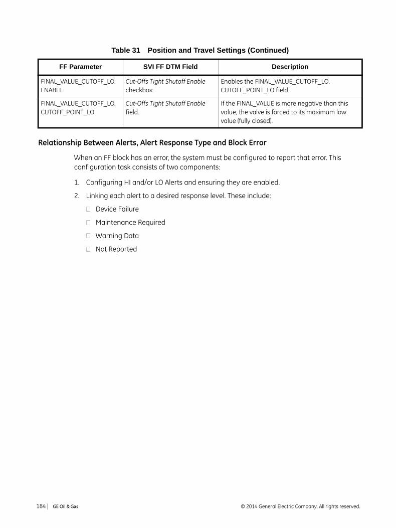
Relationship Between Alerts, Alert Response Type and Block Error
When an FF block has an error, the system must be configured to report that error. This configuration task consists of two components:
1. Configuring HI and/or LO Alerts and ensuring they are enabled.
2. Linking each alert to a desired response level. These include:
Device Failure
Maintenance Required
Warning Data
Not Reported
FINAL_VALUE_CUTOFF_LO.ENABLE
Cut-Offs Tight Shutoff Enable checkbox.
Enables the FINAL_VALUE_CUTOFF_LO. CUTOFF_POINT_LO field.
FINAL_VALUE_CUTOFF_LO. CUTOFF_POINT_LO
Cut-Offs Tight Shutoff Enable field.
If the FINAL_VALUE is more negative than this value, the valve is forced to its maximum low value (fully closed).
Table 31 Position and Travel Settings (Continued)
FF Parameter SVI FF DTM Field Description
© 2014 General Electric Company. All rights reserved.184 | =GE Oil & Gas

Appendix A. Fault State Processing
This section explains how the fault state is processed in the SVI FF.
The fault state can be initiated from multiple sources:
“Initiate Fault Sate from the Host”
“Fault Sate Conditions Detected by AO block” on page 2
“Fault Sate Conditions Detected by Transducer Block” on page 3
“Fault state condition is detected and processed by the position control hardware and software” on page 3
Initiate Fault Sate from the Host
The host may drive the entire device to fault state by setting the SET_FSTATE parameter to SET. The Fault State related I/O option (IO_OPTS) determines the reaction of the Analog Output or Discrete Output function block - whether the action is simply to hold, or to move to FSTATE_VAL.
If Analog Output block is in AUTO, CAS or RCAS mode and if I/O Option IO_OPTS bit 6 (Fault State to value) is:
Set, the OUT parameter of the block is set to the value defined in FSTATE_VAL. FF specification recommends that FSTATE_VAL value is close to the de-energized position.
NOT set, the OUT parameter of the block remains unchanged - the valve keeps the position set before the fault state is initiated.
The Transducer block then follows the setpoint received from the output block.
When the CLEAR_FSTATE parameter is set to CLEAR, the block normal processing is restored.
The discussion that follows uses the AO block as an example. However this can occur through the DO block as well.
NOTE
© 2014 General Electric Company. All rights reserved. Masoneilan SVI FF Instruction Manual =| 1

Fault Sate Conditions Detected by AO block
The AO block monitors multiple conditions and goes to Fault State if:
The CAS_IN input is not updated for a user-configurable number of block executions in a row and the block is in CAS (cascade) mode.
The status of the received data in CAS_IN is Initiate Fault State and the block is in CAS mode.
The RCAS_IN input is not updated and the block is in RCAS (remote cascade) mode.
The status of the received data in RCAS_IN is Initiate Fault State and the block is in RCAS mode.
The Fault State related I/O option (IO_OPTS) determines the reaction of the Analog Output function block - whether the action is simply to hold, or to move to FSTATE_VAL. If I/O Option IO_OPTS bit 6 (Fault State to value) is:
NOT set, the OUT parameter of the block remains unchanged - the valve keeps the position set before the fault state is detected.
Set, the OUT parameter of the block remains unchanged for the duration defined in FSTATE_TIME parameter. If the conditions causing the Fault State persist, the OUT parameter is then set to the value defined in FSTATE_VAL. FF specification recommends that FSTATE_VAL value is close to the de-energized position.
The Transducer block follows the setpoint received from the output block. When I/O Option IO_OPTS bit 6 is:
NOT set - the setpoint follows the same point.
Set - the setpoint tracks the FSTATE_VAL position.
Once the condition causing Fault State is removed, the normal processing is restored and the block follows the setpoint provided in the input.
© 2014 General Electric Company. All rights reserved.2 | =GE Oil & Gas

Fault Sate Conditions Detected by Transducer Block
In AUTO mode, the transducer block monitors the setpoint received from the AO.OUT parameter via the TB.FINAL_VALUE.
If the value received has bad status (bad value received from communications, AO block in OOS mode, etc.) or if the value is not updated (AO is not scheduled or a changed configuration is incorrect), the behavior in the TB is defined by the XD_FSTATE.XD_FSTATE_OPT and XD_FSTATE.FSTATE_TIME parameters. For the first several seconds (defined by XD_FSTATE.FSTATE_TIME), the valve follows the last good setpoint. After that, XD_FSTATE.XD_FSTATE_OPT defines the behavior as follows:
XD_FSTATE.XD_FSTATE_OPT = 0: the valve continues staying in position.
XD_FSTATE.XD_FSTATE_OPT = 1: the valve goes to fully closed position (expected to be near 0%, subject to stops tolerances).
XD_FSTATE.XD_FSTATE_OPT = 2: the valve goes to fully open position (expected to be near 100%, subject to stops tolerances).
XD_FSTATE.XD_FSTATE_OPT = 3: the valve goes to the position, specified in XD_FSTATE. FSTATE_VALUE. FF specification recommends that XD_FSTATE.FSTATE_VALUE value is close to the de-energized position.
Once the condition causing the Fault State is removed, normal processing is restored and the block follows the setpoint provided in the TB.FINAL_VALUE.
Fault state condition is detected and processed by the position control hardware and software
If the failure is detected by the position control software or in the hardware and the valve can not be controlled, the positioner's output is de-energized, which lets the spring to push the valve.
Going to fully energized position (open for ATO, closed for ATC) is subject to supply pressure availability and commensurate with the spring range.
For double-acting positioners without a spring, going to fully energized position (open for ATO, closed for ATC) is subject to supply pressure availability.
CAUTION
CAUTION
Masoneilan SVI FF Instruction Manual =| 3© 2014 General Electric Company. All rights reserved.

This page intentionally left blank.

Appendix J. Views
Views
Table 32 lists the views, view parameters and gives a general description of its purpose.
Table 32 VIEWS
View Values
View1: Dynamic analog values related to the valve position control
1 ST_REV12 FINAL_VALUE17 FINAL_POSITION_VALUE23 WORKING_SP24 WORKING_POS49 SUPPLY_PRESSURE54 ACTUATOR_A_PRESSURE55 ACTUATOR_B_PRESSURE56 ATMOSPHERIC_PRESSURE57 PILOT_PRESSURE60 TEMPERATURE63 IP_DRIVE_CURRENT90 SETPOINT91 ACTUAL_POSITION
View2: Basic Configuration View 1 ST_REV2 TAG_DESC3 STRATEGY4 ALERT_KEY71 UI_CUSTOM_CONFIGURATION83 UI_ACCESS_CONTROL84 UI_LANGUAGE93 ALERT_ACTION
© 2014 General Electric Company. All rights reserved. Masoneilan SVI FF Instruction Manual =| 189

View3: Dynamic analog values related to the valve position control
1 ST_REV12 FINAL_VALUE17 FINAL_POSITION_VALUE23 WORKING_SP24 WORKING_POS49 SUPPLY_PRESSURE54 ACTUATOR_A_PRESSURE55 ACTUATOR_B_PRESSURE56 ATMOSPHERIC_PRESSURE57 PILOT_PRESSURE60 TEMPERATURE63 IP_DRIVE_CURRENT90 SETPOINT91 ACTUAL_POSITION
VIEW3.1: Values related to the Discrete Inputs and Outputs in the device
1 ST_REV72 FAILED_STATE73 FINAL_VALUE_D74 FINAL_POSITION_VALUE_D75 FINAL_VALUE_DINT76 FINAL_POSITION_VALUE_DINT77 DISCRETE_OUTPUT_1_STATE78 DISCRETE_OUTPUT_2_STATE79 DISCRETE_INPUT
View3.2: Values related to the errors detected in the device
1 ST_REV5 MODE_BLK MODE_BLK6 BLOCK_ERR11 XD_ERROR_POS48 XD_ERROR_PRESSURE61 XD_ERROR_TEMPERATURE85 APP_MODE86 COMPLETE_STATUS94 ALERT_STATE95 ALERT_COUNTERS
View3.3: Provides histogram data 37 POSITION_HISTOGRAM39 POSITION_ERROR_HISTOGRAM
View3:4: Extremes reached in the device since power up
111 POSITION_EXTREMES112 PRESSURE_EXTREMES113 TEMPERATURE_EXTREMES114 IP_CURRENT_EXTREMES
Table 32 VIEWS (Continued)
View Values
© 2014 General Electric Company. All rights reserved.190 | =GE Oil & Gas

View3.5: Block Alarm status 1 ST_REV7 UPDATE_EVT8 BLOCK_ALM96 WORKING_TIMES
View4: Valve configuration 1 ST_REV13 FINAL_VALUE_RANGE14 POSITION_LIMITS15 FINAL_VALUE_CUTOFF_HI16 FINAL_VALUE_CUTOFF_LO20 CUSTOM_CONTROL_SET23 TRAVEL41 XD_FSTATE46 READBACK_SELECT88 OPEN_STOP_ADJUSTMENT89 SETPOINT_SOURCE
View4.1: Pressure range configuration 1 ST_REV50 PRESSURE_RANGE
View4.2: Position and travel alert status and configuration
1 ST_REV25 DEVIATION_ALERT26 POSITION_HIHI_ALERT27 POSITION_HI_ALERT28 POSITION_LO_ALERT29 POSITION_LOLO_ALERT30 TRAVEL_ACCUMULATION_A_ALERT31 TRAVEL_ACCUMULATION_B_ALERT
View4.3: Position and travel alert continued 1 ST_REV33 CYCLE_COUNTER_A_ALERT34 CYCLE_COUNTER_B_ALERT38 NEAR_CLOSED_ALERT40 SETPOINT_TIMEOUT_ALERT97 WORKING_TIME_ALERT
View4.4: Pressure temperature and current alerts 1 ST_REV51 SUPPLY_PRESSURE_HI_ALERT52 SUPPLY_PRESSURE_LO_ALERT53 SUPPLY_PRESSURE_LOLO_ALERT61 TEMPERATURE_HI_ALERT62 TEMPERATURE_LO_ALERT64 IP_DRIVE_CURRENT_HI_ALERT65 IP_DRIVE_CURRENT_LO_ALERT
Table 32 VIEWS (Continued)
View Values
Masoneilan SVI FF Instruction Manual =| 191© 2014 General Electric Company. All rights reserved.

This page intentionally left blank.

Appendix K. References
The following is a list of useful references to additional documentation:
FOUNDATION Fieldbus Application Guide 31,25 kbit/s Intrinsically Safe Systems AG-163 Revision 2.0 (can be found on: http://www.fieldbus.org/images/stories/enduserresources/technicalreferences/documents/instrinsciallysafesystems.pdf)
FOUNDATION Fieldbus Application Guide 31.25 kbit/s Wiring and Installation AG-140 Revision 1.0 (Can be found on: http://www.fieldbus.org/images/stories/enduserresources/technicalreferences/documents/wiringinstallationguide.pdf)
FOUNDATION Specification Function Block Application Process DOCUMENT: FF-890 REVISION: FS 1.8.
© 2014 General Electric Company. All rights reserved. Masoneilan SVI FF Instruction Manual =| 193

This page intentionally left blank.


© 2014 General Electric Company. All rights reserved.2 | =GE Oil & Gas
DIRECT SALES OFFICE LOCATIONS
AUSTRALIA Brisbane Phone: +61-7-3001-4319 Fax: +61-7-3001-4399
Perth Phone: +61-8-6595-7018 Fax: +61-8-6595-7299
ITALY Phone: +39-081-7892-111 Fax: +39-081-7892-208 JAPAN Chiba Phone: +81-43-297-9222 Fax: +81-43-299-1115
SOUTH AFRICA Phone: +27-11-452-1550 Fax: +27-11-452-6542 SOUTH & CENTRAL AMERICA AND THE CARIBBEAN Phone: +55-12-2134-1201 Fax: +55-12-2134-1238
Melbourne KOREA SPAIN Phone: +61-3-8807-6002 Phone: +82-2-2274-0748 Phone: +34-93-652-6430 Fax: +61-3-8807-6577 Fax: +82-2-2274-0794 Fax: +34-93-652-6444
BELGIUM MALAYSIA UNITED ARAB EMIRATES Phone: +32-2-344-0970 Phone: +60-3-2161-0322 Phone: +971-4-8991-777 Fax: +32-2-344-1123 Fax: +60-3-2163-6312 Fax: +971-4-8991-778
BRAZIL Phone: +55-11-2146-3600 Fax: +55-11-2146-3610
CHINA Phone: +86-10-5689-3600 Fax: +86-10-5689-3800
FRANCE Courbevoie Phone: +33-1-4904-9000 Fax: +33-1-4904-9010
GERMANY Ratingen Phone: +49-2102-108-0 Fax: +49-2102-108-111
INDIA Mumbai Phone: +91-22-8354790 Fax: +91-22-8354791
New Delhi Phone: +91-11-2-6164175 Fax: +91-11-5-1659635
MEXICO Phone: +52-55-3640-5060 THE NETHERLANDS Phone: +0031-15-3808666 Fax: +0031-18-1641438 RUSSIA Veliky Novgorod Phone: +7-8162-55-7898 Fax: +7-8162-55-7921 Moscow Phone: +7 495-585-1276 Fax: +7 495-585-1279 SAUDI ARABIA Phone: +966-3-341-0278 Fax: +966-3-341-7624 SINGAPORE Phone: +65-6861-6100 Fax: +65-6861-7172
UNITED KINGDOM Wooburn Green Phone: +44-1628-536300 Fax: +44-1628-536319 UNITED STATES Massachusetts Phone: +1-508-586-4600 Fax: +1-508-427-8971 Corpus Christi, Texas Phone: +1-361-881-8182 Fax: +1-361-881-8246 Deer Park, Texas Phone: +1-281-884-1000 Fax: +1-281-884-1010 Houston, Texas Phone: +1-281-671-1640 Fax: +1-281-671-1735
* Masoneilan, SVI, and ValVue are registered trademarks of the General Electric Company. FOUNDATION Fieldbus is a trademark of the FOUNDATION Fieldbus organization. Other company names and product names used in this document are the registered trademarks or trademarks of their respective owners.
© 2014 General Electric Company. All rights reserved.
GEA31031D 06/2014