marvin lock status sensor integration instructions lock status s… · · 2018-03-12marvin lock...
TRANSCRIPT

2018-03-0519915804
Marvin Lock Status SensorIntegration Instructions
ABSTRACT: The following instructions are intended to instruct home automation professionals where various sen-sors are located in Marvin product. It will also show how to remove and replace window and door components toallow access to sensors and wiring where necessary.Usage Dates: 12/18/2017 to present.
W A R N I N G !
These products contain chemicals known to the State of California to cause cancer and birth defects or other repro-ductive harm.
W A R N I N G !
Drilling, sawing sanding, or machining wood products generates wood dust, a substance known to the State of Cal-ifornia to cause cancer. Avoid inhaling wood dust or use a dust mask or other safeguards for personal protection.
W A R N I N G !
Always practice safety! Wear the appropriate eye, ear and hand protection, especially when working with powertools.
I M P O R TA N T
Marvin recommends that integration occurs within the transmitter pocket or within the frame of the window. Doorintegration is wireless only, integration should occur only in the factory prepared radio transmitter pocket.
To view an Online version of this document scan the QR code below.

2018-03-05 2 Marvin Lock Status Sensor19915804 Integration Instructions
General SpecificationsMarvin Lock Status Sensors (LSS) provide a way to integrate our products with home automation solutions. The LSSis comprised of a sensor and magnet integrated into the window or door with little or no visibility to preserve thebeauty of your Marvin Windows and Doors.
The following products are available with LSS:
• Clad Ultimate Double Hung*
• Clad Ultimate Casement
• Clad Ultimate Glider*
• Multi-Slide Door
• Inswing French Door
• Outswing French Door
• Sliding French Door
*The Lock Status Sensor detects an open or closed status. A “locked” status is inferred from the presence of theAuto-Lock feature, which activates the locking mechanism when the operating panel is closed
Compatibility
There are size limitations for the transmitter and access to a terminal block within the transmitter is required:
• The LSS is compatible with a wide range of radiotransmitters.
• Modifying any third-party transmitters may void thethird-party manufacturer’s warranty.
• Modifying the factory prepped transmittercompartment will void the Marvin Limited Warranty.
AT T E N T I O N
Modification of the sensor, sensor housing, sensor wiring and the radio transmitter compartment will void Marvin'sLimited Warranty. There may be performance and safety concerns associated with modifying these components andwe do not recommend modifying these components.
Frequently Asked Questions
Additional questions not covered in this instruction regarding technical aspects and integration with different securitysystems can be found at our Lock Status Sensor page.

2018-03-05 3 Marvin Lock Status Sensor19915804 Integration Instructions
CLAD ULTIMATE CASEMENT
I M P O R TA N T
WIRELESS INTEGRATION USING A RADIO TRANSMITTER (provided by others): Do not finish or seal (caulking/painting) head jamb cover joints to facilitate future battery replacement.
CUCA-Accessing Transmitter Compartments and Wire Leads
1. Unlock and open the sash.
2. Remove the head jamb part stop. Gently pry along the part until the stop is separated from the frame. See Figure 1.
Figure 1
H i n t
The part stops can also be removed by hand. Grasp thestop and gently rock the part toward the interior whilepulling firmly down to remove.
3. With the head jamb part stop removed you will have access to the routed transmitter pocket and the wire leads for either hardwired or wireless connections. See Figure 2.
Figure 2
4. To replace the part stop, unlock and open the sash. Push the part stop up into the head jamb so the connecting barb seats into the groove completely.
I M P O R TA N T
When reinstalling head jamb stop, be sure not to pinchthe wire leads.See Figure 3.
1 Transmitter pocket
2 Rout in part stop to accommodate transmitter.
1 3.675" (about 3 5/8")
2 1.14" (about 1 1/8")
3 22 gauge lead wires
2018-03-05 4 Marvin Lock Status Sensor19915804 Integration Instructions
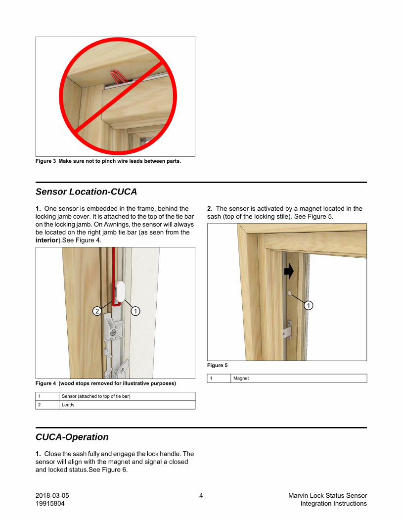
Figure 3 Make sure not to pinch wire leads between parts.
Sensor Location-CUCA
1. One sensor is embedded in the frame, behind the locking jamb cover. It is attached to the top of the tie bar on the locking jamb. On Awnings, the sensor will always be located on the right jamb tie bar (as seen from the interior).See Figure 4.
Figure 4 (wood stops removed for illustrative purposes)
2. The sensor is activated by a magnet located in the sash (top of the locking stile). See Figure 5.
Figure 5
CUCA-Operation
1. Close the sash fully and engage the lock handle. The sensor will align with the magnet and signal a closed and locked status.See Figure 6.
1 Sensor (attached to top of tie bar)
2 Leads
1 Magnet

2018-03-05 5 Marvin Lock Status Sensor19915804 Integration Instructions
Figure 6
CUCA-Mulled Units with Hardwired Integration
I M P O R TA N T
Splicing Wires: Marvin recommends that splices occurwithin the factory routed transmitter pocket.
2. Vertical Mulls: first unlock, open the sash and remove the jamb covers on the window that houses the sensor.
3. Fish wire through the factory provided 1/4" hole located in the head jamb.See Figure 7.
Figure 7
4. Optional through jamb setup: Operate the lock so the tie bar is fully extended. Then use a 1/4” drill bit to bore a hole through the top area of the jamb (above the extended tie bar) into the adjoining unit’s jamb until you have access behind the covers.See Figure 8.
Figure 8
1 Sensor attached to locking rod (stops are cut away for illustration)
2 Magnet

2018-03-05 6 Marvin Lock Status Sensor19915804 Integration Instructions
5. Horizontal Mulls: first unlock, open the sash and remove the jamb covers on the window that houses the sensor. Operate the lock so the tie bar is fully extended. Then use a 1/4” drill bit to bore a hole through the top area of the jamb (above the extended tie bar) into the R.O. See Figure 9.
Figure 9
I M P O R TA N T
Make sure there is enough slack in the wire to accom-modate the tie bar’s full range of motion.

2018-03-05 7 Marvin Lock Status Sensor19915804 Integration Instructions
Clad Ultimate Double Hung Next Generation
CUDHNG-Sensor Location
I M P O R TA N T
WIRELESS INTEGRATION USING A RADIO TRANSMITTER (provided by others): Do not finish or seal (caulking/painting) head jamb cover joints to facilitate future battery replacement.
6. Two sensors are embedded in the frame. One is in the jamb receiver, this indicates the bottom sash is closed. The other is hidden within the head jamb transmitter cover and indicates the top sash is closed.See Figure 10 and Figure 11.
Figure 10
Figure 11
7. The sensors are activated by magnets located in the latch bolt of the bottom sash and another in the top rail of the top sash. See Figure 12.
Figure 12
1 Jamb receiver (shown with cover removed)
1 Head jamb transmitter cover (shown removed) (transmitter provided by others)
1 Magnet in top rail of top sash
2 Latch bolt of bottom sash (exterior view) with magnet hidden with-in end of bolt

2018-03-05 8 Marvin Lock Status Sensor19915804 Integration Instructions
CUDHNG-Operation
1. Close both sash fully. This will activate the auto lock at the check rail. At this point, the magnets will align with the sensors and signal a closed and locked status for both top and bottom sash.See Figure 13.
Figure 13
1 magnet hidden in end of latch bolt

2018-03-05 9 Marvin Lock Status Sensor19915804 Integration Instructions
CUDHNG-Accessing Transmitter Compartments and Wire Leads
1. Unlock and open the top sash.
2. To access the transmitter compartment and wire leads, remove the head jamb transmitter cover. Starting at one end grasp and pull straight down. The wiring and top sash sensor are attached to the cover.See Figure 14.
Figure 14 Transmitter shown provided by others.
CUDHNG-Mulled Units with Hardwired Integration
1. Vertical Mulls: Open and unlock the sash. See Figure 15.
Figure 15
2. Fish wire through the factory provided 1/4" hole located in the transmitter pocket rout in the head jamb. See Figure 16.
Figure 16
3. Horizontal Mulls: Fish the wire through the 1/4" (6) hole in the head jamb. Route the wire along the mull to the rough opening. See Figure 17.
Figure 17
1 Fish wires through hole in head jamb rout
1 Angled hole in sill of transom
2 Hole in transmitter route (provides a path for hole in transom sill)
3 Splice inside transmitter pocket

2018-03-05 10 Marvin Lock Status Sensor19915804 Integration Instructions
Clad Ultimate Glider
CUGL-Sensor Location
1. The lock status sensor is embedded behind the top keeper hardware on the stationary sash. The magnet that activates the sensor is in the top latch bolt of the operator sash. See Figure 18.
Figure 18
CUGL-Operation
1. Close the operator sash until the auto-lock activates. The magnet in the latch bolt will align with the lock status sensor once the bolt is locked. The sensor will indicate a closed and locked status. See Figure 19.
Figure 19
1 Sensor behind keeper on stationary sash
2 Magnet in top bolt of operator sash

2018-03-05 11 Marvin Lock Status Sensor19915804 Integration Instructions
CUGL-Accessing Transmitter Covers and Wire Leads
1. Open the interior sash to the fully open position. Depress the sash retainer bar latch and slide the retainer bar completely free of the sash. See Figure 20.
Figure 20
2. Grasp both sides of the sash, tilt the top inward and remove the sash from the frame. See Figure 21. Reverse the procedure to reinstall the sash.
Figure 21
3. Remove the head jamb part stop by inserting a flat head screwdriver in the notch at the end of the part stop. Pry down on the part taking care not to damage the wires routed in that location. See Figure 22.
Figure 22
1 Sash retainer bar
1 Head jamb part stop
2 Transmitter pocket with sensor wires

2018-03-05 12 Marvin Lock Status Sensor19915804 Integration Instructions
CUGL-Mulled Units for Hardwired Applications
Vertical Mulls: Remove the knock-out tab from theplastic transmitter cover at the head jamb to rout wiresinto the rough opening.See Figure 23.
Figure 23 Transmitter cover shown removed for illustrative pur-poses.
NOTE: The transmitter cover is not removable once thewindow is installed.
I M P O R TA N T
Horizontal Mulls: Only a wireless sensor installation iscompatible for a horizontal mulled CUGL unit.
1 Remove knock-out tab (from inside the pocket)
2 Fish the wires through the hole in transmitter cover

2018-03-05 13 Marvin Lock Status Sensor19915804 Integration Instructions
Ultimate Sliding and Swinging Doors
Doors-Sensor Location
1. There is one sensor in all the door platforms located under the exterior door handle escutcheon.See Figure 24
Figure 24 Swinging Door shown with cladding cut away
2. One exception is the Ultimate Multi-Slide door (MMSD). The sensor on this door is located under the interior door handle escutcheon behind the linkage bar. See Figure 25.
Figure 25
Patio Door Hardware
1. When attaching patio door hardware to the panels. Take note of the position of the micro-switch sensor located in the thumb turn area on the panel. The angle of the tail-piece(s) on the hardware and micro-switch should be tilted toward the glass. On keyed handles, remove the extended tail-piece and discard.See Figure 26.
I M P O R TA N T
If the sensor does not activate when the door is locked,it may mean that the micro-switch is turned 180 de-grees. Remove the handle, turn the micro-switch 180degrees and retest.
Figure 26
1 Sensor
1 Angle of tail-piece and micro-switch should be tilted toward glass
2 Discard extended tail-piece

2018-03-05 14 Marvin Lock Status Sensor19915804 Integration Instructions
Doors-Operation
I M P O R TA N T
Integration of the LSS for all door offerings is wirelessonly.
2. On Swinging Doors: close the door completely until the latch engages in the strike. Turn the thumb turn to lock. Once locked, the locking sensor will activate and your door will be considered closed and locked. See Figure 27.
Figure 27
3. On Sliding Doors: close the door completely until the latch engages the strike. Lock handle with lever or thumb-turn (depending on product). Once locked the locking sensor will activate and your door will be considered closed and locked. See Figure 28.
Figure 28 Sliding Patio Door shown.
4. On Multi-Panel Sliding Doors (MPS): close the door completely until the latch engages the strike. Slide the lock handle up to engage the multi-point lock. Once locked the sensor will align with the magnet and signal a closed and locked status.See Figure 29.
Figure 29

2018-03-05 15 Marvin Lock Status Sensor19915804 Integration Instructions
Doors-Accessing Transmitter Covers and Wire Leads
1. Unlock and open the door.
2. On the edge of the active panel, remove the transmitter cover plate by removing the screws fastening the plate to the side of the panel. Use the provided hook and loop strip affixed to the inside of the rout to position your transmitter (remove backing and adhere to your transmitter). See Figure 30.
Figure 30 Door stiles
H i n t
On swinging doors, center your transmitter (providedby others) vertically in the rout, making sure the trans-mitter does not interfere with the motion of the lock rodwhen operated. See Figure 31.
Figure 31 Swinging door stile (cut away)
3. On all doors with keyed cylinders. Remove the t-shaped adapter from the micro-switch located on the exterior side of the panel. Use a needle nose pliers and discard. See Figure 32.
Figure 32
NOTE: On some non-keyed cylinders, the tail-piece willbe long enough to push the t-shaped adapter from themicro-switch area.
1 Transmitter cover plate
2 Transmitter (provided by others)
3 Hook and loop affixed inside transmitter pocket
1 Transmitter centered in pocket (provided by others)
2 Lock rod