marschalk aquarius ii bladder pumps - geotech … marschalk aquarius ii bladder assembly is a welded...
TRANSCRIPT

1
Marschalk Aquarius II Bladder Pumps
Installation and Operation Manual

1
TABLE OF CONTENTS
Chapter 1: System Description ................................................................... 3 Function and Theory .................................................................................. 3 System Components .................................................................................. 4
Chapter 2: System Installation .................................................................... 6 Bladder Pump .............................................................................................. 6 Chapter 3: System Operation ................................................................... 7 Bladder Pump Operation ........................................................................... 7 Selecting an Air Source ............................................................................. 7 Determining PSI .......................................................................................... 7 Flow rates .................................................................................................... 8
Chapter 4: System Maintenance ............................................................... 11 Marschalk Aquarius II Bladder Pump ..................................................... 11 Bladder Replacement ............................................................................... 11
Chapter 5: System Troubleshooting ......................................................... 13 System Troubleshooting .......................................................................... 13 System Troubleshooting cont... .............................................................. 14
Chapter 6: System Specifications ............................................................. 15 Chapter 7: System Schematic ................................................................... 16 Chapter 8: Replacement Parts List ........................................................... 17
The Warranty ............................................................................................. 22 Equipment Return Policy ......................................................................... 22 Equipment Decontamination ................................................................... 22

2
NOTE
DOCUMENTATION CONVENTIONS This manual uses the following conventions to present information:
An exclamation point icon indicates a WARNING of a situation or condition that could lead to personal injury or death. You should not proceed until you read and thoroughly understand the
WARNING message.
A raised hand icon indicates CAUTION information that relates to a situation or condition that could lead to equipment malfunction or damage. You should not proceed until you read and thoroughly understand the CAUTION message.
A note icon indicates NOTE information. Notes provide additional or supplementary information about an activity or concept.
WARNING
CAUTION

3
Chapter 1: System Description Function and Theory
The Marschalk Aquarius II Bladder Pumps operate with a unique action ideal for both gentle low-flow sampling and higher volume purging. Electro/pneumatic controllers permit timed on/off cycles of compressed air to alternately pressurize (squeezing the flexible bladder to displace water out of the pump) and exhaust allowing the pump bladder to refill. Fluid enters the pump through the “Lower Head” inlet check valve located at the bottom of the Bladder Assembly, via hydrostatic pressure (automatically by submergence) refilling the bladder with fluid. Compressed air enters the space between the bladder and the interior of the Outer Stainless Steel Housing pressurizing the bladder and pushing water up the discharge tubing. During the pressure cycle the intake check valve closes and the discharge check valve opens. The compressed air squeezes the bladder, pushing the fluid up the discharge tube. The discharge check valve prevents back flow from the discharge tubing during the exhaust / fill cycle. The bladder is refilled by hydrostatic pressure and the cycle repeats. Compressed air does not contact the sample! The bladder prevents contact between the pump drive air outside the bladder and the water inside the bladder.
NOTE: Bladder pumps operate more efficiently when submerged under at least 10 feet of water. Lower submergence requires longer fill times or vacuum assist. For all of your Bladder Pump Controller requirements, it is recommended that you use only Geotech / Marschalk Controllers. Contact GEOTECH to discuss which controller will best suit your specific site requirements.

4
System Components The Marschalk Aquarius II Bladder Pump consists of four main parts, the Bladder Assembly, Bladder, Intake Head and the Outer Housing.
Bladder Assembly The Marschalk Aquarius II Bladder Assembly is a welded assembly consisting of four 316 Stainless Steel components, the Upper and Lower Head and two Spanner Rods. (see figure 1, page 5).
Bladder The Bladder is constructed of a proprietary inert virgin grade PTFE polymer resin and is extruded with no markings or lubricants.
The Bladder is installed onto the Bladder Assembly and secured in place with two 316 Stainless Steel, Low-profile reusable clamps, providing a true zero leak seal.
Intake Head The Intake Head is constructed of 316 Stainless Steel.
Outer Housing The Outer Housing is constructed of 316 Stainless Steel. Viton O-rings provide the high pressure seals between the Bladder Assembly and the Intake Head.
Intake screen Assembly (Optional) The Intake Screen Assembly is constructed of 316 Stainless Steel components and is easily removable for field maintenance. The Intake Screen Assembly is intended to protect and extend the life of the bladder material by preventing particulates larger than a .023 diameter from entering the pump (see warranty, page 22).

5
System Components
Figure 1
BLADDER ASSEMBLY
INTAKE SCREEN ASSEMBLY (OPTIONAL)
(UPPER HEAD)
(SPANNER RODS)
(LOWER HEAD)
OUTER HOUSING
BLADDER
CLAMPS, BLADDER
(Low-profile reusable)
O-RING, OUTER HOUSING
INTAKE HEAD
INTAKE HEAD SET SCREW (FULL DOG)
O-RING, LOWER BLADDER ASSEMBLY
O-RING, BLADDER
LOWER CHECK RETAINING SCREW
UPPER CHECK RETAINING SCREW
O-RING, UPPER CHECK RETAINING SCREW
CHECK BALL, SS
HOSE BARB (DISCHARGE)
EYEBOLT
HOSE BARB (AIR-IN)
CHECK BALL, SS
O-RING, OUTER HOUSING
O-RING, BLADDER

6
Chapter 2: System Installation
Bladder Pump The Marschalk Aquarius II Bladder Pump is engineered for easy installation and use. As an Option, dedicated Bladder Pumps can be shipped from GEOTECH with the tubing attached. Well identifications and pump intake depths (supplied by the customer) are written on the tags connected to the tubing and on the tubing bags.
Marschalk Aquarius II Bladder pumps can also be used portably. Connect the air line tubing (.170 x .25) to the Air-in Hose barb and attach the sample line (.250 x .375) to the Fluid Discharge Hose barb. Make sure the tubing is pushed down until it bottoms out at the fitting shoulder and is secure. Tubing clamps are no longer required for this connection (see figure 2).
Figure 2
NOTE: To connect the bonded tubing to your Bladder Pump in the field, first trim the
sample line tubing (.250 x .375) approximately 1/4” shorter than the air line tubing. This allows for a neater connection to the pump head and keeps the tubing from buldging or bowing out if one side is longer than the other.
Attach the pump suspension cable to the pump’s support hanger using the low profile “Quick Link”. Ensure the attachment of both tubing and support cable are secure and tight before lowering the pump into the sampling well.
SUPPORT HANGER
FLUID DISCHARGE HOSEBARB (TUBING REQUIRED .250 X .375)
AIR-IN HOSEBARB (TUBING REQUIRED .170 X .250)

7
Chapter 3: System Operation Bladder Pump Operation
Fluid enters the pump through the Intake Head at the bottom of the pump and the bladder fills with fluid. Compressed air enters the space between the bladder and the interior of the Outer Housing, the inlet check valve closes and the discharge check valve opens. The compressed air squeezes the bladder pushing the fluid up the discharge tube. The discharge check valve prevents backflow from the discharge tubing during the fill cycle.
Selecting an Air Source
The following explanation is based on a .170 ID air supply tubing. To determine the required capacity of the air source used, calculate the air consumption as follows. With 100 ft. of air line tubing in or out of the well, the air consumption is 125 cubic inches per cycle, with 6 cycles per minute (average).
Example: For 100 ft. of tubing you will need 125 cu. in. x 6 per min. which equals 750 cu. in. / min. or 45,000 cu. in. / hr. For each additional 100 ft. add 59 cu. in. If you plan to use an air compressor we advise that you use one with a reserve tank to insure proper air supply to the pump.
Determining PSI
CAUTION
It is important NEVER to apply excessive pressure to the bladder during the pump cycle. The proper setting of the pumping pressure will reduce wear and prevent permanent deformation of the bladder. Always start pumping with a pressure as set on the Controller, of 3-5 psig, regardless of pump depth and head pressure. During each successive pumping cycle, increase pumping pressure in 3-5 psi increments until water flow is observed at the surface. Once water is flowing at the surface the pressure regulator can be used to regulate flow. Example; higher pressure will empty the bladder contents quickly, lower the pressure and you will decrease the flow rate and it will take more time to empty the bladder. By using the pressure regulator in concert with the electro-pneumatic timers you can control the flow rate to less than 50mls/minute.

8
Flow Rates
Flow rates are based on the Marschalk Aquarius II Bladder Pump modeled PERFORMANCE CURVE (see figures 4, 5, 6, pages 8, 9, 10).
Figure 4 – Performance Curve
Aq
ua
riu
s II 2
4" B
lad
de
r P
um
p P
erf
orm
an
ce
Cu
rve
0.0
00
0.1
00
0.2
00
0.3
00
0.4
00
0.5
00
0.6
00
0.7
00
050
100
150
200
250
300
De
pth
of
pu
mp
, fe
et
GPM
0.0
0
1.5
0
3.0
0
4.5
0
6.0
0
7.5
0
9.0
0
10.5
0
SCF/gal

9
Figure 5 – Performance Curve
Aq
ua
riu
s II 4
2" B
lad
de
r P
um
p P
erf
orm
an
ce
Cu
rve
0.0
00
0.1
00
0.2
00
0.3
00
0.4
00
0.5
00
0.6
00
0.7
00
050
100
150
200
250
300
De
pth
of
pu
mp
, fe
et
GPM
0.0
0
1.0
0
2.0
0
3.0
0
4.0
0
5.0
0
6.0
0
7.0
0
SCF/gal

10
Figure 6 – Performance Curve
Aq
ua
riu
s II 6
0" B
lad
de
r P
um
p P
erf
orm
an
ce
Cu
rve
0.0
00
0.1
00
0.2
00
0.3
00
0.4
00
0.5
00
0.6
00
0.7
00
050
100
150
200
250
300
De
pth
of
pu
mp
, fe
et
GPM
0.0
0
1.0
0
2.0
0
3.0
0
4.0
0
5.0
0
6.0
0
7.0
0
SCF/gal

11
Chapter 4: System Maintenance Marschalk Aquarius II Bladder Pump As with any pump, scheduled or periodic maintenance should be performed, according to your sampling program and specific site conditions. Generally, the more turbid or sandy your water, the more often you should maintain and clean your pumps. In addition, pumps that are in wells with high concentrations of Total Dissolved Solids (ex. iron, calcium, and manganese) may be subjected to mineral deposits and require more frequent cleaning (see System Components, figure 1, page 5). Decontaminate or replace parts as needed, then reassemble. Inspect all check balls for wear and replace as necessary. Inspect all O-rings for rigidity splits or cracks and replace as necessary. Disassemble the Bladder Pump per the following instructions:
Bladder Replacement When replacing an existing Bladder use the following instructions:
• Pull the pump from the well. It will be necessary to remove the air and sample lines from the pump as well as the pump suspension cable.
• Using a 3/32” Allen wrench, remove the Intake Head set screw. Gently pull and twist the
Intake Head to remove it from the Outer Housing (see figure 1, page 5). • Remove the Outer Housing (see figure 1). • Using a pair of Oetiker clamping pliers, remove the upper and lower Bladder clamps. At
this time, inspect the O-rings for rigidity, splits or cracks and replace them as necessary (see figure 1).
• The Bladder can now be removed for cleaning or replacement.

12
• If you are pumping with a dedicated system that has a high concentration of dissolved mineral solids, it is recommended that you remove and inspect the Upper and Lower SS Check Balls for deposit build-up. If this deposit build-up is present, clean as necessary and reinstall. Mineral deposition can cause the Check Balls to become permanently seated in the Check Valve. If mineral precipitation on the Check Balls becomes a problem, a replacement PTFE Check Ball is available.
• Reinstall the bladder by reversing the sequence of steps outlined above. The low profile
bladder clamps must be installed directly over the Bladder o-rings to insure a good seal. • Reinstall the Intake Head into the Outer Housing. NOTE to make reassembly easier use a little DI water to lubricate the o-rings and the Stainless Steel. • Reinstall the Intake Head set screw.
WARNING
This set screw connection between the Bladder Assembly’s “Lower Head” and the Intake Head is a critical structural element of the Aquarius II Bladder Pump (see figure 1, page 5). Do not over-tighten the screw when assembling the pump. Tighten the set screw only until it bottoms out in the groove of the “Lower Head”. Improper assembly can seriously decrease the burst resistance of the pump. Do not pressurize the pump for any reason unless it is in a well. If the Intake Head is improperly installed and the pump is pressurized outside of the well the pump may come apart suddenly causing injury.

13
Chapter 5: System Troubleshooting System Troubleshooting Problem: Solutions:
1) “Charge” (Pressurize) and “Exhaust” (Fill) times are not set correctly.
Check and adjust charge and exhaust cycle times (i.e. if charge time is too long or if exhaust and charge time is too short).
2) Possible compromise in air line tubing.
Check air line pump for leaks. If needed, repair using compression union or replace tubing.
3) Check pump intake screen for blockage and clean as needed. 1) Check drawdown level of water in the well.
Ensure the pump is fully submerged and off of the bottom of the well.
2) Check psi at the regulator and adjust as necessary (see page 7).
3) Check for kinks in the discharge line.
4) Check pump intake screen for obstructions.
5) Charge time is too long or exhaust time is too short; causes pressure build up in pump, causing the pump not to fill.
6) Check power source, assure a strong reliable power supply. If using and old or weak battery, the control valves may not operate properly.
Air is cycling thru controller,
but will not pump…
Controller is cycling but the pump stops producing water…

14
System Troubleshooting cont...
1) Over charging pump.
Reduce charge cycle time so that charge cycle ends as fluid discharge trails off.
Inspect pump for compromised bladder or o-rings.
2) Pump is being over pressurized.
Reduce psi to what is necessary to overcome pumping head (see page 7 for determining psi).
3) Check discharge line for holes or kinks.
Repair using compression union or replace tubing. 1) Remove Hose barb on pump discharge outlet.
Check the check ball seat for debris. Clean and re-install. 1) Bladder could be collapsed due to over pressurizing (typically
found in low-submergence scenarios). 2) Mineral deposits have caused the Check Balls to permanently
seat in the Check Valve(s).
Getting air bubbles in sample line…
Discharge line drains back into pump…
Pump stops pumping...
15
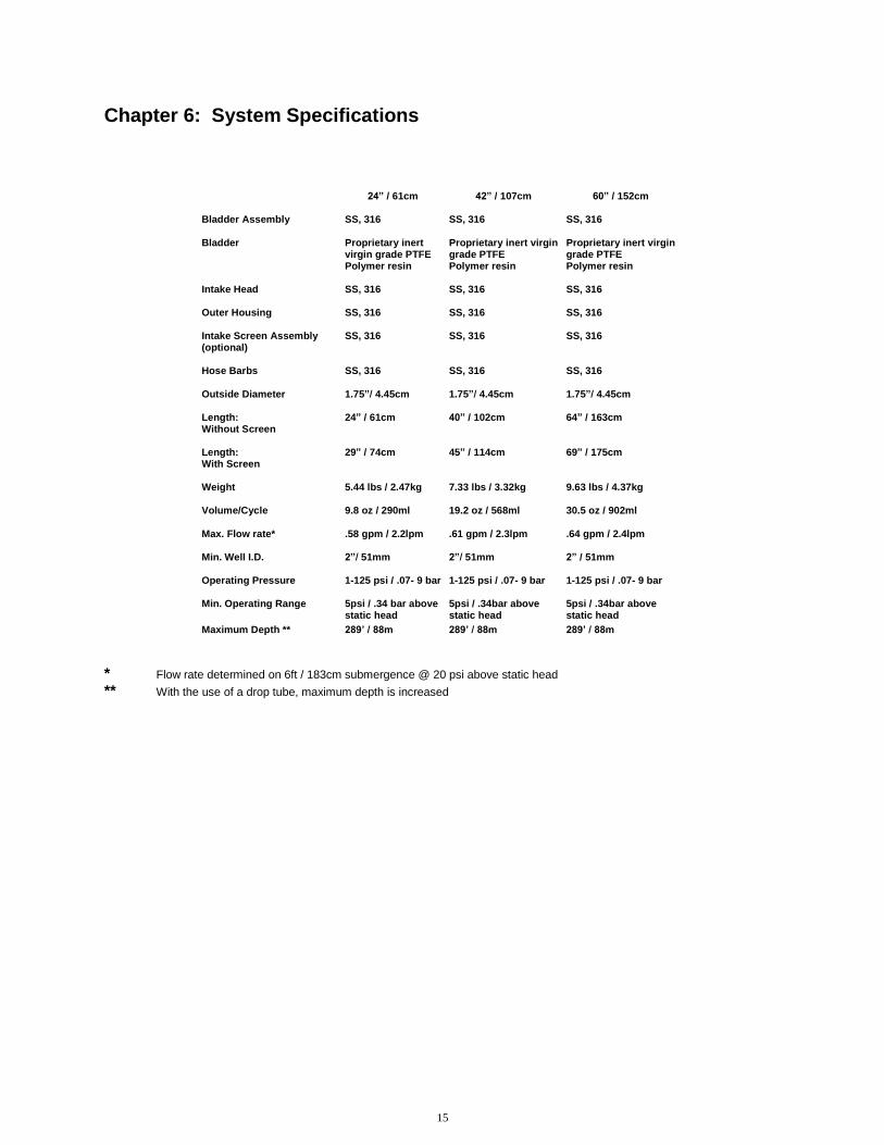
Chapter 6: System Specifications
24” / 61cm 42” / 107cm 60” / 152cm Bladder Assembly
SS, 316
SS, 316
SS, 316
Bladder Intake Head
Proprietary inert virgin grade PTFE Polymer resin SS, 316
Proprietary inert virgin grade PTFE Polymer resin SS, 316
Proprietary inert virgin grade PTFE Polymer resin SS, 316
Outer Housing Intake Screen Assembly (optional) Hose Barbs
SS, 316 SS, 316 SS, 316
SS, 316 SS, 316 SS, 316
SS, 316 SS, 316 SS, 316
Outside Diameter 1.75”/ 4.45cm 1.75”/ 4.45cm 1.75”/ 4.45cm
Length: Without Screen
24” / 61cm 40” / 102cm 64” / 163cm
Length: With Screen
29” / 74cm 45” / 114cm 69” / 175cm
Weight
5.44 lbs / 2.47kg 7.33 lbs / 3.32kg
9.63 lbs / 4.37kg
Volume/Cycle
9.8 oz / 290ml 19.2 oz / 568ml 30.5 oz / 902ml
Max. Flow rate*
.58 gpm / 2.2lpm .61 gpm / 2.3lpm
.64 gpm / 2.4lpm
Min. Well I.D.
2”/ 51mm 2”/ 51mm
2” / 51mm
Operating Pressure 1-125 psi / .07- 9 bar
1-125 psi / .07- 9 bar
1-125 psi / .07- 9 bar
Min. Operating Range
5psi / .34 bar above static head
5psi / .34bar above static head
5psi / .34bar above static head
Maximum Depth **
289’ / 88m 289’ / 88m 289’ / 88m
* Flow rate determined on 6ft / 183cm submergence @ 20 psi above static head ** With the use of a drop tube, maximum depth is increased

16
Chapter 7: System Schematic
24”
42”
60”

17
Chapter 8: Replacement Parts List Aquarius II Bladder Pump Qty Description Part # 1 Bladder Assembly – 24” 21150060 1 Bladder Assembly – 42” 21150062 1 Bladder Assembly – 60” 21150065 1 Outer Housing – 24” 21150058 1 Outer Housing – 42” 21150061 1 Outer Housing – 60” 21150066 1 Bladder – 24” 21150057 1 Bladder – 42” 21150063 1 Bladder – 60” 21150064 1 Hose Barb – (air-in) 21150019 1 Hose Barb – (discharge) 17200360 2 Check Ball, SS 11150020 1 Upper Check Retaining Screw 11150058 1 Lower Check Retaining Screw 11150054 1 intake head set screw (full dog) 11150055 1 O-ring, Upper Check Retaining Screw 16600136 1 O-ring, Lower Bladder Assembly 11150049 2 O-ring, Bladder 11150056 2 O-ring, Outer Housing 11150057 1 Eyebolt 16600133 2 Clamps, Bladder (Low-profile reusable) 11150163 1 Intake Head 21150059 1 Intake Screen Assembly (optional) 81150023 2 Check Ball, PTFE (optional ) 17500083

18
Notes

19
Notes

20
Notes

21
Notes

22
The Warranty
For a period of one (1) year from date of first sale, product is warranted to be free from defects in materials and workmanship. Geotech agrees to repair or replace, at Geotech’s option, the portion proving defective, or at our option to refund the purchase price thereof. Geotech will have no warranty obligation if the product is subjected to abuse, misuse, or inability to use this product. User assumes all other risk, if any, including the risk of injury, loss, or damage, direct or consequential, arising out of the use, misuse, or inability to use this product. User agrees to use, maintain and install product in accordance with recommendations and instructions. User is responsible for transportation charges connected to the repair or replacement of product under this warranty.
Equipment Return Policy
A Return Material Authorization number (RMA #) is required prior to return of any equipment to our facilities, please call our 800 number for appropriate location. An RMA # will be issued upon receipt of your request to return equipment, which should include reasons for the return. Your return shipment to us must have this RMA # clearly marked on the outside of the package. Proof of date of purchase is required for processing of all warranty requests. This policy applies to both equipment sales and repair orders.
FOR A RETURN MATERIAL AUTHORIZATION, PLEASE CALL OUR SERVICE DEPARTMENT AT 1-800-833-7958 OR 1-800-275-5325.
Model Number: ________________
Serial Number: ________________
Date: ________________
Equipment Decontamination
Prior to return, all equipment must be thoroughly cleaned and decontaminated. Please make note on RMA form, the use of equipment, contaminants equipment was exposed to, and decontamination solutions/methods used. Geotech reserves the right to refuse any equipment not properly decontaminated. Geotech may also choose to decontaminate equipment for a fee, which will be applied to the repair order invoice.

Geotech Environmental Equipment, Inc 8035 East 40
th Avenue Denver, Colorado 80207
(303) 320-4764 ● (800) 833-7958 ● FAX (303 322-7242 email: [email protected] website: www.geotechenv.com