mars - defense technical information centerdtic.mil/dtic/tr/fulltext/u2/a138578.pdf · line form,...
TRANSCRIPT

Research Note 84-61
BRADLEY INFANTRY FIGHTING VEHICLE PROCEDURES GUIDES: EVALUATION
Margaret S. Salter
a 0 Litton Systems, Inc.
Joh.o C. MoreyArmy Research Institute
Submitted by
Seward Smith, Chief
ARI FIELD UNIT AT FORT BENNING, GEORGIA
and
Harold F. O'Neil, Jr., Director
TRAINING RESEARCH LABORATORY
_ _MARS 1984
_ _ A
U. S. Army
Research Institute for the Behavioral and Social Sciences
February 1984
Approved for public release; distribution unlimited.
This report has been cleared for relas to the Defense Technical Information Center (DTIC). It has been given noother primary distribution and will be available to recluestors only through DTIC or other reference services sucha the National Technical Information service (NTIS). The views, opinions, and/or findings contained in thisreport are those of the author(s) and should not be construed as an official Department of the Army position.policy, or decision, unless so designated by other official documentation.
ITC FILE COPY s 0" t ' ~ ~~ 05 0,44 .. i- ..

UNCLASSIFIEDSECURITY CLASSIFICATION OF THIS PAGE ("on Dae Entered)
REPORT DOCUMENTATION PAGE RED CSRECTIoNs1. REPORT NUMBER e246 .GQVT ACESSIO".O 3. IPIENT'S CATALOG NUMBER
Research Note 84-61 f1 Ii( 4~ r64. TITLE (and Subtitle) S. TYPE OF REPORT & PERIOD COVERED
BRADLEY INFANTRY FIGHTING VEHICLE PROCEDURES Research NoteGUIDES : EVALUATION
6. PERFORMING ORG. REPORT NUMBER
7. AUTHOR(*) 0. CONTRACT OR GRANT NUMBER(a)
Margaret S. Salter, Litton Mellonics MDA 903-80-C-0545and Dr. John C. Morey, U.S. Army ResearchTnstitute. Fort Bennlna Field Unit
9. PERFORMING ORGANIZATION NAME AND ADDRESS 10. PROGRAM ELEMENT. PROJECT, TASKAREA & WORK UNIT NUMBERS
Mellonics System Development, Litton SystemsInc., 1001 W. Maude Avenue, Sunnyvale, CA 94086 2Q263744A795
11. CONTROLLING OFFICE NAME AND ADDRESS 12. REPORT DATE
U.S. Army Research Institute for the Behavioral February 1984and Social Sciences, 5001 Eisenhower Avenue, 13. NUMBER OF PAGES
Alexandria, Virginia 22333 5414. MONITORING AGENCY NAME & ADDRESS(I dlfferent from Controlling Office) IS. SECURITY CLASS. (of thie report)
UNCLASSIFIEDISa. DECL ASSI FICATION/ DOWNGRADING
SCHEDULE
16. DISTRIBUTION STATEMENT (of this Report)
Approved for public release; distribution unlimited
Approved for public release; distribution unlimited.
17. DISTRIBUTION STATEMENT (of the abstract entered In Block 20, If different from Report)
18. SUPPLEMENTARY NOTES
Technical quality of this research monitored by Seward Smith.
19. KEY WORDS (Continue an reverse side If neceeary and Identify by block number)
Procedure guidesJob aidFighting vehiclesInfantrySPAS
20, AISRACr (Cmu an m ebb N ne-ee -a I~Itr by block nmber)
This report presents the results of a field verification of the usefulness,completeness, and effectiveness of the Bradley Infantry Fighting Vehicle _Procedures -uide: Driver and Bradley Infantry Fightin- Vehicle Procedures-Guide: Commander and Gunner. The development of the Guides and verificationmethodology are presented. Soldiers who had recently completed an institu-tional course in one of the three crew positions served as subjects. Subjectmatter experts also reviewed the Guides. The results indicate the Guides areuseful and! effectjlva. They ar,b heat- tim al n a~r,n.a n4Am A,,v 4ng 4vn4t4a1...
D CrLm ASS3 ImFIOA oO I Tv As IS OmeLETIE tII2 UNCLASSIFIEDSECURiITY CLAWFtCATIOIC OF THIS PiAGiE (W Data Entered)
I1[1 lilln in i nmA

SECURITY CLASSIFICATION OF THIS PAOK(Whan Data gmimE)
Item 20 (cont'd)
i training and as aids during refresher or cross-training. Recommendationsfor publishing format and distribution are presented.
ii UNCLASSIFIED
SECURITY CLASSIFICATION OF THIS PAOEWMbefl Data Entwere
- -- ----

ACKNOWLEDGEMENTS
Litton Mellonics Systems Development gratefully acknowledges the manycontributions to this project by U.S. Army military and civilian personnel.Special thanks to:
- U.S. Army Research Institute, Fort Benning Field Unit
Dr. John C. MoreyMr. Hal C. StraselMr. Rick MoffatMr. Phil Hurst
- U.S. Army Infantry School, Directorate of Training and Doctrine
LTC George HobsonSFC Notley P. Reavis, IIISSG Paul R. RobersonSSG Mark S. Vought
- U.S. Army Infantry School, Weapons Gunnery and Maintenance Department
- Officers, NCOs, and students in the BIFV Commander and BIFV Gunner Courses
- U.S. Army Training Center, Infantry Training Group Officers, NCOs, andstudents in the BIFV Driver Course
.4,,
I I,
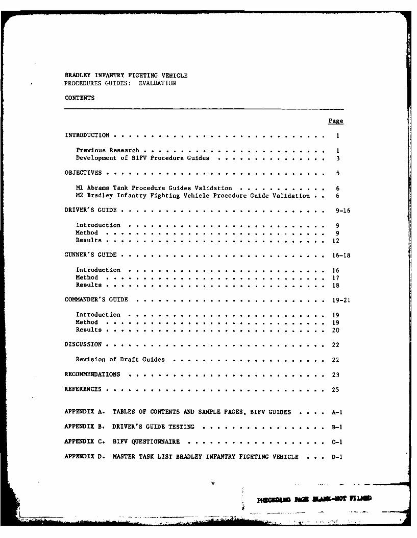
BRADLEY INFANTRY FIGHTING VEHICLEPROCEDURES GUIDES: EVALUATION
CONTENTS
Page
INTRODUCTION...............................1
Previous Research .. .. .. .. .. .. .. .. .. .. .. .. 1
Development of BIFV Procedure Guides . . . . . . . . o o . . . 3
OBJECTIVES........... ... . . . . .. . . . . 5
Ml Abramns Tank Procedure Guides Validation e o...........e & 6
M2 Bradley Infantry Fighting Vehicle Procedure Guide Validation o . 6
DRVE' GUIDEo.......... ......... .. .. o...o. . ..... 9-16
Introduction........................... a a *...... o 9Method.o.............. .......... ......... 9Results........... .e a a a...o....o...... ae ** ao aa12
GUNNER'S GUIDE . . . . . o . .... .. .. ... ... o. .. . ... 16-18
Introduction... ..... e e * .@ e o o * o o o o o a m o. 16Method eeoa*eoeo . e @ o a o...e.e.o................ e17
Results............................................................ 18
COMMANDER'S GUIDE.o..................... . . . . . o . . o 19-21
Introduction e * * o @ o o o o o o e o * * o o o a *........19
Method ooo*oe@o .e . * e e *.@.@.@.*.e.e...........19
Results o o o a . . o . . o .. . . . . . . . . 20
DISCUSSION............................................22
Revision of Draft Guides............................22
RECOMMENDATIONS . .o......... . . . . . . . . . . . . 23
REFERENCES o o . . . . . . . . . . . o e * o . & . * . 25
APPENDIX A. TABLES OF CONTENTS AND SAMPLE PAGES, BIFV GUIDES . o . - A-i
APPENDIX B. DRIVER'S GUIDE TESTING o o - o . o . o o o o o . . . . . B-i
APPENDIX C. BIFV QUESTIONNAIRE oo.o.. o.... o... o.o..o C-i
APPENDIX D. MASTER TASK LIST BRADLEY INFANTRY FIGHTING VEHICLE . . . D-1
v
PI6UUDN~ MA4W IMUM

INTRODUCTION
For a number of years, the Army Research Institute (ARI) has been involved
in efforts related to improving training for soldiers in both collective and
individual skills. At the same time, ARI has been associated with the develop-
ment and field testing of the Bradley Infantry Fighting Vehicle (BIFV) and its
associated training devices. In support of the U.S. Army Infantry School and
Director of Training Development's attempt to maximize the effectiveness of
the Bradley M2 Vehicle, ARI has further expanded BIFV training materials
with the construction of a Procedural Guide for each of the three major
operator positions; (1) Bradley Commander; (2) Gunner; and, (3) Driver. The
Bradley Commander's tasks include overall responsibility for the vehicle, and
target and weapon selection. He can take over firing of the turret weapons if
necessary, and he insures that preventive maintenance checks and services are
performed as needed throughout the vehicle. The gunner is responsible for the
turret in general and for the operations and maintenance of the major weapons
systems. He coordinates with the commander and supervises ammunition resupply.
The driver's tasks focus on the operation of the vehicle itself, and on
maintenance checks on the hull and driver's areas. The three position-specific
guides cover both operational and maintenance tasks; they do not attempt to
address tactics and battle drills. The guides are not intended for use as a
substitution for the existing Bradley Technical manual. They do provide a
supplementary source of information useful in the operational and training
environment.
Previous Research
The Bradley Procedure Guides are modeled after those created by the
Army Research Institute - Fort Knox Field Unit for the Ml Abrams Tank (Vaughan,1

Silbernagel, & Goldberg, 1981). The Ml Guides were produced in response to
the need to improve performance levels for various MI tasks. The Ml, with its
complex set of systems, is similar to the Bradley M2 in that there are some
tasks which require a great number of steps. Some steps are very complicated
and many tasks require careful sequencing of steps. The major training
reference for the Ml is the technical manual (TM 9-2350-225-10) which contains
a highly proceduralized set of tasks and detailed pictures of equipment. The
manual is complete and accurate, but it presents a number of problems.
It is cumbersome because of its size, the index is difficult for the operators
to use, and only one manual is issued per vehicle. These problems were seen
as possible contributing factors to the relatively poor performance of tank
tasks by Ml commanders, gunners, drivers and loaders (Goldberg & Campbell,
1983).
Accordingly, Procedure Guides for each Ml crewman were produced, in an
effort to provide an alternative training aid (i.e., a supplement to the TM
which would present fewer problems for the individuals who tried to use it).
In the Ml Guides, tasks which are not complicated are presented in line-by-
line form, with the names of tasks listed in the correct sequence. More
complex tasks are presented in a flowchart format with decision trees at
choice points. The steps within a procedure are sequenced, and the use of
symbols highlights the subtasks. Warnings and cautions are presented, as well
as indications as to when vehicle indicator lights are critical. The termi-
nology is identical to that found in the technical manual and a table of
contents is provided. Each operator guide also contains a checklist of the
preventive maintenance checks and services for which that operator is respon-
sible. The Commander's Guide contains a Master Checklist which enables him to
supervise the other crew members.
2

The Ml Guides were field tested at Fort Knox and Fort Hood and found to
be useful and effective (Goldberg & Campbell, 1983). However, general per-
formance on the tasks was still so low that it was felt that perhaps the tasks
had not been mastered at the time of testing. This would indicate that
additional job aids during training might have been beneficial. Although some
persons were found to have difficulty with the format of the guides, it was
felt that this problem would probably disappear as trainees became more
familiar with the style. Some persons made errors which indicated that they
were not thoroughly familiar with the tasks, and did not recognize abbreviations.
Also, it seemed that during training the individuals had not been required to
perform each substep in an accurate manner. Training focus had been placed on
the task as a whole, rather than on the elements.
However, the Procedure Guides were found to be as effective as the
Technical Manual and a TM checklist, and they were very well received by the
trainees. It was the conclusion of the Fort Knox researchers that the Guides
showed definite utility, and could be beneficial if introduced early in
training with command emphasis to insure that they were being utilized. Task
performance accuracy might then increase and full utilization could be made of
the Ml vehicle.
Development of BIFV Procedure Guides
Because of the favorable results of the Knox testing, very few changes
were made in M2 format during the development of the M2 Bradley Infantry
Fighting Vehicle Guides. The required sequence of tasks was identified and
the more complex steps or procedures were detailed. The symbols indicating
decisions, warnings, and lights employed in the Ml Guides were adopted for use
with the Bradley Guides. (See Appendix A for symbols and sample pages from
each guide.) Visually, each page is broken by boxes or other attention
3

getters and, as much as possible, only one task is presented on each page to
provide maximum clarity without unduly wasting space. The only abbreviations
used are those found in the technical manual or on the driver, gunner, and
commander instrument panels. Whenever there seemed to be any doubt as to
whether a trainee might understand a procedure, more steps or explanations
were included to minimize confusion.
The tasks for inclusion in the guides were identified from the tasks
presented in TM 9-2350-250-10-1, Fighting Vehicle, Infantry, M2, Hull, and
TM 9-2350-250-10-2, Fighting Vehicle, Infantry, M2, Turret. The tasks were
further refined by analysis of Soldier's Manuals, (FM 11MI0, -20, -30, -40,
Soldier's Manual, Fighting Vehicle Infantryman), by informal discussions with
members of the Fort Benning Bradley Task Force, and by consultation with NCOs
responsible for training soldiers in operation of the Bradley. (Appendix D
contains the entire task list.)
Each BIFV operator task was separately examined for possible procedurali-
zation in light of the following criteria:
1. If the task was judged to be relatively simple with no substeps, or
was one which could be performed by trainees using skills typically acquired
prior to entry level training, the task was designated a checklist task.
Proceduralization was indicated only if the task difficulty exceeded this
minimum difficulty level.
2. Some tasks are practiced so many times during training that they are
overlearned by trainees. The tasks are taught, reinforced, taught again, and
practiced and tested throughout training. Tasks of this nature have lost
their complexity, and were thus retained on a checklist of tasks requiring
performance, but not proceduralization.
3. If the task was one in which correct performance or sequencing of
steps was in any way critical to the safety of personnel, to the integrity4

of the vehicle, or to accomplishment of the designated mission, then
proceduralization was indicated.
4. Some tasks are performed very rarely by BIFV crews and thus do
not acquire sufficient practice to insure long-term retention of the indiv-
idual task steps. Proceduralization of these tasks helps insure that important
steps, if forgotten over time, will be available for quick reference.
5. Some tasks require proceduralization because of their lack of delay
tolerance; e.g., misfire procedures. These tasks must be learned so thoroughly
that reaction is immediate, and the crew member responsible for performing the
task does not have time to look at a proceduralized guide. These tasks are
detailed in a proceduralized form for quick refresher training, or in case of
emergency conditions when the tasks need to be performed by persons not
accustomed to performing them.
Tasks which met the proceduralization criteria were analyzed separately,
and substeps presented in the Ml Guide format with terminology and sequencing
identical to the Technical Manual. Then the tasks were separated by operator
position and presented in a logical order within each guide. The vehicle
starting operations and the checks which would be made as a mission begins are
included, as well as normal and unusual operations. Procedures are included
for loading and firing the weapons systems, for shutting down the vehicle, and
performing immediate action when necessary. Also included are lists of
preventive maintenance checks and services (PMCS) which each operator is
responsible for doing or supervising, before, during, and after operations.
(See Appendix A for Tables of Contents for M2 Procedure Guides.)
OBJECTIVES
The objective of this testing was to ascertain the usefulness, complete-
ness and efxecti eness of the BIFV Procedure Guides. It was designed to5
I ,

determine whether the soldiers, during their training cycles, could use the
Guides, and whether the abbreviated format was sufficiently comprehensive to
enable trainees to perform the tasks correctly. The testing was also intended
to expose the trainees to the Guides, to see how well they liked them as job
and/or training aids.
The Bradley M2, with its 9 or 10 man crew, has three main duty positions,
and 6 or 7 crew members who ride in the squad area in the back and are respon-
sible for the firing port weapons. Many of the Gunner and Commander tasks are
interchangeable and could allow for cross-training, but the Driver does not
learn any of the Gunner or Commander tasks.
Ml Abrams Task Procedure Guides Validation
Since the Ml Guides were precursors to the BIFV Guides, the Fort Knox
testing will be reviewed. The Ml Guides were tested against the technical
manual and a technical manual checklist. Subjects were tank trainees and
experienced operators from Fort Knox and Fort Hood.
A series of Driver, Loader, Gunner, and Commander tasks were performed by
each subject. The Guides were evaluated on the basis of performance accuracy,
time to perform a task, and time to locate a task in the training aid (TM,
Procedure Guide or Checklist). The Fort Knox testing found that the Guides
were useful, were easier to use than the other aids, and did not decrease
performance accuracy.
M2 BIFV Procedure Guide Validation Approach
The statistical approach to evaluation which was used for the Ml guides
was judged to be inappropriate for the conditions available for testing the
soundness of the Bradley guides, for a number of reasons. First, though the
Ml analyses were performed on small samples, even smaller numbers of trained
Bradley Commanders, Gunners, and Drivers are presently available to try out6

each of the three position-specifir 6uides. The lack of position cross-
traininp prevented combining groups to enlarge the sample for each separate
guide.
Secondly, since the available subjects were trainees just completing )n,-
of the courses designed to teach the tasks assigned to a particular Bradley
operator position, the level of performance when using a BIFV Procedure Cuilde
did not appear to be an issue. The past experience of course instructors
indicated that there would be little variance from a unitormly high level of
task performance by the subjects recently completing training.
Another focus of the Fort Knox testing procedure was the time it took
subjects to perform the tasks. It proved difficult to determine if
subjects were slow because they were thorough or because they were un-
familiar with the material. Similarly, others could have been finished
quickly because they were knowledgeable or because they hurried and did not
take the time to complete all the steps. For the Bradley, some tasks are
timed for end of course testing, but the method is one where an upper limit is
given and all subjects must perform the task within that particular time
frame. The actual time is of little importance as long as it falls within the
limit. Further, since during training many of the tasks have no time .'-ndard,
to impose one during testing might inappropriately affect the subjects'
performance as they strived to meet or beat an arbitrary standard. Accordingly,
the M2 Guides tasks were not tested for time to complete each task.
The Fort Knox testing also compared the time required to locate tasks in
the Guides, the Checklist, or in the Technical Manual. Since the number of
pages contained in the Bradley Procedure Guides is so much smaller than in the
TMs (24 in the Driver's Guide vs. more than 500 in the Hull TM; 85 in the
Commander Guide vs. more than 600 in the Turret TM), task location should be
easy for anyone who has had the time to read the Table of Contents. Since the7

BIFV trainees did not have time to study the Procedure Guides, it was decided
that time to locate was not a meaningful measure at this time. Also, the TM
might have been dog-eared or otherwise marked after weeks of use; the most
frequently used page numbers may have been memorized, giving an artificially
fast time-to-locate score.
Accordingly, testing of the BIFV Guides was done on a more informal
basis than that of the Ml, emphasizing the usefulness and effectiveness of the
guides, rather than attempting a statistical comparison of the utility of the
guides versus the manual. Since the guides are meant to supplement the
manual, rather than supplant it, this choice seems defensible.
Validation of the Bradley Infantry Fighting Vehicle Guides consisted of
several separate steps. A sample of the operator and maintenance tasks
presented in the Guides was tested in a motor pool setting at Fort Benning.
(Practical constraints prevented testing any tasks related to weapons systems
or vehicular movement.) Subjects were soldiers who were at different stages
in their Bradley training. In each case, a trainee was tested on an individual
basis, although the actual testing methods differed for the three Guides.
The trainees were also given a questionnaire designed to measure their
perceived abilities to perform Bradley related tasks. The questionnaire does
not attempt to measure the trainees' actual abilities to perform the tasks;
rather, the intention was to obtain an impression of how well they felt they
could perform. (See Appendix C for the questionnaire and results.)
The results of the evaluation approach are presented separately for
each of the three Bradley Guides in the following sections. The discussion
section presents the results of a final review of the content of the guides by
SMEs, and recommendations for implementation of the guides.
8
. o--- -. .--

DRIVER'S GUIDE
Introduction
The BIFV Driver's Course is the introduction to the 1IM Bradley MOS. The
course is taught by the Infantry Training Group (ITG) as a three week add-on
to the regular 12-week One Station Unit Training (OSUT) course offered at Fort
Benning. Therefore, the attendees are newly trained recruits with no unit
experience. Many of the graduates of the Driver's Course are eventually
assigned to Bradley driver duty positions in units; others become members of
the dismounted Bradley squad and responsible for the on-board firing port
weapons and other squad duties.
Method
The subjects for the testing of the Driver's Guide were 17 soldiers
who had completed all requirements of the IlM OSUT add-on except for the
End-of-Course Test. Subjects were gathered in a classroom setting and the
purpose of the research was explained, together with the assurance that their
performance would in no way impact on their Army careers. They were then
given a questionnaire concerning their impressions and perceptions of how well
they felt they could perform certain Bradley tasks. (This questionnaire, and
the rationale for its administration is discussed in Appendix C.) Copies of
the Driver's Guide were then distributed to each student. They were encouraged
to look at the guides and the format, and then the instruction or general
information page was explained in detail (see Appendix B, Driver's Guide
Testing). After each symbol and the Table of Contents had been explained, the
trainees were told to turn to a specific page in their guides, and the steps
of the task, Slave Start: Start Vehicle with Outside Power Source, were
9

covered, one at a time, with the use of the symbols and boxes again explained.
The testing began after each student had had an opportunity to examine the
guide.
The students were then taken individually to vehicles in the motor pool
area. They were assigned numbers, and were called in order; each of the five
experimenters taking the next person in numerical order, so that the process
would not be slowed down by any one trainee. All subjects performed the same
sample of tasks, in an order counter-balanced for sequence of task performance,
and training aid (Guide or TM) used. The orders of task presentation for each
subject and the particular training aid used for each task are presented in
Table 1. Total time spent with each subject averaged at least 30 minutes.
Four tasks normally performed by the driver were tested and each of these
tasks consisted of many substeps.
Task 1: During Operations Preventive Maintenance Checks and Services
(PMCS). During operations, the driver must make a number of checks within his
compartment. Performance of these checks was observed. Everyone did PMCS
using either the TM or the Procedure Guide. With one exception, each of the
tasks required within PMCS was familiar to the subjects. The unfamiliar task,
*Operate the Personnel Heater, had been mentioned, but never actually performed
because of the summertime heat. During testing, subjects were requested to
operate the heater (briefly) either with the TM as guide or by following the
*Procedure Guides steps.
Task 2: Start to Stop. Another element of testing was the Start through
Shutdown procedures. This included preparing the driver's station, actually
starting the engine, shutting it down at the end, and turning on and off all
equipment. The experimenters were aware that all of the subjects were
capable of following the techniques described in the TM, and probably did not
10
-. J i, ..

Table I
Order of Presentation of TasksDriver's Guide Testing
Subject First Second ThirdNumber Task Task Task
1 PMCS - DG NV - None S - S - PG2 PMCS - TM NV - PG S - S - PG3 PMCS - PC NV - TM S - S - PG4 S - S - PG PMCS - TM NV - None5 S - S - PG PMCS - PG NV - PG6 S - S - PG PMCS - TM NV - TM7 NV - None S - S - PG PMCS - PG8 NV - PG S - S - PG PMCS - TM
9 NV - TM S - S - PG PMCS - PG10 PMCS - TM NV - None S - S - PG11 PMCS - PG NV - PG S - S - PG12 PMCS - TM NV - TM S - S - PG13 S - S - PG PMCS - PG NV - None14 S - S - PG PMCS - TM NV - PG15 S - S - PG PMCS - PG NV - TM
omit <NV - None> <S - S - PG> <PMCS - TM>16 NV - PG S - S - PG PMCS - PG17 NV - TM S - S - PG PMCS - TM
PMCS - Preventive Maintenance Checks and ServicesS - S - Start Through Shutdown Procedure
NV - Night Viewer InstallationTM = Technical ManualPC - Procedure GuideNone - No Performance Aid
TOTALS: PMCS - TM - 8
PMCS - PG - 9S - S - PG - 17
NV -None - 5NV -TM - 6
NV -PG 6
1

need any performance aids. However, all subjects were told to use the
Procedure Guides for each step, even if they did not want or need to.
Task 3: Install Driver's Night Viewer. Installation of the driver's
night viewer involves removing the driver's periscope from the hatch cover,
unstowing and connecting the night viewer, and stowing the periscope. Finally,
the night viewer is restowed and the periscope reinstalled. Subjects were
assigned to one of three groups; to use the TM, the Procedure Guides, or no
performance aid at all.
Task 4: Erect/Stow Swim Barrier. The task erect and stow the swim
barrier is a group effort, supervised by the driver. Normally, as many crew
members as are present will help in installing the barrier; in training,
groups of six are used. Accordingly, the students were divided into groups of
6, 6, and 5 and asked to erect the barrier using only the Procedure Guide.
A leader was picked at random from the groups and he was given the Guide.
When the barrier was erected, one of the cadre NCOs inspected it to insure
that no step had been omitted or incorrectly performed. After approval,
the barrier was removed and stowed, again following the Procedure Guide.
Results
In general, performance accuracy was very high and scoreable errors in
tasks or subtasks were not systematically distributed. So few problems were
experienced that failures appeared to be based on individual differences,
rather than on any particular defects within the Procedure Guides. Therefore,
the presentation of the results of testing focuses on the kinds of errors made
by the few individuals who made any errors.
The trainees were so thoroughly trained in most cases that it was diffi-
cult to slow them down long enough tu get them to use the guides or the TM.
This was countered in some degree by each experimenter's insistence that the12

subjects read the steps aloud as they performed them. (The original intent
of the reading aloud had been to ascertain if reading ability affected per-
formance.) Even with this method of forcing attention to each step, the
subjects kept trying to move ahead quickly since they felt they needed no aids
to perform the next steps.
An additional problem concerned serviceability of some of the vehicles.
There were several instances of inoperable equipment, or deficiencies that
prevented the trainees from performing exactly as required. The constraints
of time and the numbers of vehicles available for use precluded changing
vehicles when difficulties were found. (One benefit of faulty equipment was
noted, however; where problems were found, the students were very quick to
state that such failures should be reported on Form 2404 for unavailable
equipment. At least one lesson had been very thoroughly learned.) The
results of the driver testing are presented by task in the following section.
PMCS. The trainees had no difficulty in understanding the format of the
PMCS Procedure Guides Checklist. There was a tendency to perform several
steps at one time, such as checking several lights and gages at once, but
trainees indicated that they tended to do this while using the TM as well as
when using the Procedure Guide. Several lost their places in the list,
perhaps due to unfamiliarity with it. When prompted by the experimenters,
they had no difficulty in performing the tasks. Each experimenter worked with
both the TM and the Procedure Guides checklists, and none noted any particular
differences in trainee performance as a function of which text was being used.
Within the PMCS, the task Operate the Personnel Heater had not previously been
taught to the trainees. When the trainees came to that check, they were
instructed to follow the procedures as given in the Guides or in the TM. The
actual following of the steps proved to be no problem, but a few subjects
had difficulty in locating the personnel heater. Too, several heaters proved13
inoperable. The subjects did talk through the steps, however, and were
apparently able to understand a task on which they had not previously had
training. This indicates that the task could be performed correctly on the
basis of the limited information presented within the Procedure Guides.
Start-to-Stop. There was a strong tendency for the trainees to skip
ahead of the Guides in the start-to-stop procedures and begin the next step
before reading it. Some of the steps in preparing the driver's station do not
have to be performed in a set sequence, and trainees wanted to perform them in
their own particular sequence. Checking of the driver's instrument panel
gages had become so automatic that stopping to read the steps in the guides
was obviously an inhibiting and apparently frustrating factor. Several
omitted the steps requiring the sounding of the horn at ramp raising and
lowering, and at engine start. When questioned, they volunteered that they
knew no one was there because the others were inside doing other things. They
also stated, correctly, that if they had really been going to move the vehicle,
there would have been a ground guide for coordination purposes, and that they
would have used the horn as well as hand and verbal signals to communicate
with him.
A few of the trainees had difficulty with the decision point where they
were told what to do if the engine did not start. Since no engine failed
to start, no one should have had to read that section of the step. Several
trainees read both the yes and no answers, some apparently because they did
not understand the diagram; others said that they wanted to read the alternate
answer out of curiosity, although they knew that they did not need to perform
that step. Greater familiarity with the guides would certainly eliminate this
problem.
Install and Remove the Driver's Night Viewer. The only problems observed
had to do with trainee unfamiliarity with the guides and equipment failure.14

Several subjects tried to perform both the battery power and vehicle power
steps and a few lost their place in the Guides. The TM group had no difficulty.
One individual who had missed his training on this task was able to perform it
using only the guide. Other problems were equipment related. In one vehicle
the protective cover kept falling off of the eyepiece, and the trainee,
concerned about the viewing element, tried to stow the equipment at once. In
another vehicle, the driver's periscope was stuck, and could not be removed
from the hatch cover to make room for the night viewer. Subjects talked the
experimenter through the steps with no apparent difficulty.
Erect and Remove the Swim Barrier. In one swim barrier group, the
designated leader began the task, but as the task proceeded, another student
took the guide and performed in the leadership role. The reason for this was
not readily apparent, and the experimenter did not interfere. In another of
the three vehicles, there were equipment problems. The trim vane could not be
locked into an upright position and the barrier could not be erected.
The training cadre worked unsuccessfully to remedy the problem, so only two
barriers were actually erected.
Following the procedures presented no problem, and the steps contained
sufficient information to permit the task to be performed correctly and
completely. The sequencing presented some problems, as a tendency emerged
for the group to divide into sections and work on different parts of the
vehicle at the same time. Some sequencing is forced by the nature of the
task; for other parts of the task sequencing is irrelevant. Several began,
for example, to work on the rear corners of the barrier while others were
still removing the front of the barrier from stowage. Similarly, both sides
were being worked on simultaneously, and some persons were putting finishing
touches on them while others were completing the front. There was also some
tendency to ignore the guide as the subjects knew the task steps so well.15

At no time did anyone refer to the TM for help. Similar results were obtained
for removing and stowing the barrier.
In summary, the Driver's Guide was both useful and useable. The drivers
seemed comfortable with it, and were able to perform their jobs using it. In
many cases they did not need it, and it slowed their performance. Nowhere
was performance quality reduced by the guide. Subjects said they liked the
guide's size and format, and the convenience of the PMCS checklist. Several
commented on the bulkiness of the Hull Technical Manual (nearly 500 pages) and
tue fact that a pocket size guide could be carried with them. The only
commeats on the absence of pictures or diagrams were from the students whom
the experimenters had perceived as being the least comfortable with the
tasks.
Thus, for the drivers, the least skilled and least experienced of all
the persons associated with the Bradley Infantry Fighting Vehicle the Pro-
cedure Guides proved a useful, complete, and effective means of aiding
performance and reinforcing training.
GUNNER'S GUIDE
Introduction
The Gunner's Course is a four week course which covers all of the material
offered in the Driver's Course, plus turret operations and maintenance,
and the loading and firing of the BIFV weapons systems. The students are
generally E5s, with a large amount of previous Army experience. The Gunner's
Course is taught by the Weapons Gunnery and Maintenance Department (WGMD)
cadre.
16
!4

Method
The Gunner's Course was in its final week and there was very little
time not previously scheduled. The only spare time was that available during
the days when the trainees were at the firing range. Subjects were made
available during the time when they were not engaged in firing, or in riding
with those who were. The length of time required for instructions and safety
briefings, and the students' desires to utilize their break periods for
resting or lunch made it possible to test only 4 soldiers. However, since
each of these individuals was tested for 45 minutes, alone with the experi-
menter, a great deal of information was gathered.
The results of the drivers' testing had indicated that the guides
were useable, so only a few tasks were tested on the gunners using the
Procedure Guide and the TM was not tested at all. Again, the testing was
limited to non-firing tasks. The gunners were relatively experienced soldiers,
and three of the four were National Guardsmen undergoing Bradley training at
Fort Benning. Several indicated that the course was moving very fast, and
that they were not too sure of themselves on some of the procedures.
After an explanation of the purpose of the testing and a brief intro-
duction to the guides, each of the four trainees was given several gunner
tasks. They were asked to use the guides for each step, whether or not they
needed them, and were asked to read the steps aloud as they were performing
them. They operated the turret in both the manual mode and the power mode,
traversing the turret and elevating and depressing the 25mm gun. They were
also asked to perform the steps required to start up and shut down the turret.
They performed both before operation and during operation PMCS on the turret,
although they did not dry fire the weapons. They performed the proceduralized
17

steps required in checking out the deck clearance system and the operations of
the integrated sight unit. At a later time, all 25 gunners were administered
the questionnaire on perceived task performance ab'l.ity.
Results
The gunner results derived were very similar to those obtained from the
drivers. The trainees experienced no difficulty in using the guides, and they
commented favorably on their brevity and convenience. Two of the trainees had
some difficulty in pronouncing the words while reading aloud, although
they shoved no difficulty in performing the tasks. One individual who was
uncertain about a step asked for the TM diagram, but he immediately withdrew
the request. He said that he would gladly sacrifice the pictures for the
convenience of the guide. He then went on to perform the task correctly.
The PMCS checklists were useful and each man said he had done as well on
PMCS as he would have if he had been using the manual. One asked about the
deficiency-reporting system and praised the convenience of the guide, likening
it to an aviator's checklist. Again, the Procedure Guides seemed to slow the
gunner trainees down for some procedures; they wanted to combine steps : a
more convenient sequence or to do several things at the same time. The
major complaints about the guides were based on the gunners' feelings that
they did not really need to use them at this stage in training.
Some time was spent in conversation with the gunners, on the assumption
that their previous Army experience would make them perceptive about different
kinds of training aids. The general feeling was that they liked the guides
and format, and would appreciate their convenience after they had learned the
steps with the TM. They further indicated that since they were learning a
great deal of material in their course, and since it was going to be difficult
to retain all of it, the guides could be used as refreshers.
18

COMMANDER'S GUIDE
Introduction
The Bradley Commander is generally a squad leader or platoon leader, E6
through 03. At the present time, the commanders are trained in an intensive
six-week course taught by the Weapons Gunnery and Maintenance Department at
Fort Benning. They are taught the operator tasks for the entire vehicle,
including weapons and driving, swimming, special operations, and all the
maintenance tasks. Some tactical training, and live fire exercises are
included. Since the soldiers training at this level already have considerable
Army experience, some of it within armor or mechanized infantry units, training
proceeds quickly.
Method
By the time the Bradley Commander's Guide was ready for testing, a
tentative decision had been made to combine the Gunner and Commander Guides
into one book. Although the original intent was to have three separate
guides, one each for the Bradley Commander, Gunner, and Driver, as work
proceeded, it became apparent that the Commander's and Gunner's guides were
nearly identical in procedural tasks. This was due to dual controls for the
weapons systems, and the fact that the Commander shares the same view through
his eyepiece as does the Gunner.
The tasks which could have been tested for the commanders were identical
to those of the gunner, because of the limits presented by the motor pool
environment and because of the duplication of tasks between the two positions.
The training schedule was very tight, and there was little time available for
outside testing without interfering with the training schedule. The only time
that the instructors felt would be available was during the third week of the
course when the students were learning to swim the Bradley. After each group19

had erected its swim barrier, some men were made available for work with the
guide, but only one group of three could be tested.
After the purpose of the experiment was explained and the general
format of the guides explained, the men were given copies of the Commander's
Guide and were asked to read through the PMCS Master Checklist pages, de-
scribing the activities and the responsibilities of the persons assigned to
perform them. This proved to be somewhat unworkable as each of the three
tried to be the leader and instruct the others. They developed their own more
workable and efficient system. Each man took several of the checks, either 6n
the hull or in the turret area, and announced, for example, "I've got the
suspension." He then did all of the tasks in the suspension area, reading
from the Guide as he performed them. A second volunteered to do the engine
checks, and so on. They organized the tasks in a way similar to that required
by a vehicle commander. After they had finished their tasks, the three were
administered the questionnaire.
Results
The Commander Course trainees had no difficulty in conceptualizing the
PMCS checklist format, and were able to follow it and comprehend the aspects
of delegation of responsibility. No one performed a task which had already
been done by another, and they worked in a coordinated manner on items which
required two persons, such as checking light operations. It was apparent that
they took the effort seriously when they discovered a drip under the vehicle.
They spent several minutes making checks to determine the cause of the leak
even though it was not "their" vehicle and they were not accountable for it.
Another group of trainees was to be given the PMCS but the students were
very eager to get to their own swimming exercises, and to watch the progress
20

of the other groups; therefore, the plan was changed, and the experimenter
talked with 10 trainees on an informal basis and showed them the guides. They
looked at all three guides, and noted the different tasks and the format.
With only one exception, all of the students indicated that they liked the
idea of the guides as memory joggers and thought guides would be useful for
soldiers at any level. They also thought the PMCS checklists would be easy to
use.
The captain who did not like the guides stated that he expecteQ his men
to know the tasks so well that they did not need aids. If they needed help,
he would send them back to the back to the TM with its details and diagrams
until they had learned. He also indicated that he wanted a TM for PMCS so
that performance standards would remain high. Others disagreed with him at
once, indicating that the technical manuals are so bulky and have so many
words and steps not needed by a trained individual that most trained operators
do not even read the words. They also said that the PMCS performance would be
more thorough with the Procedure Guides checklists than with the TM. These
comments indicate that command emphasis will be the key in determining the
ultimate usefulness of the procedure guides. Any training material which has
the support of the instructors and the commanders will be utilized to the
fullest in whichever place it is presented; one with no support will be
discarded.
The commanders particularly expressed satisfaction with the compact size
of the guide, and the idea that each man would be issued one. Since presently
the TM is taken away at the conclusion of the Commander's Course, several of
the students asked if they could get advance or draft copies of the guides, so
they could refer to them after course completion.
21

DISCUSSION
In summary, the results of the testing support the idea that for most
procedures neither the Procedure Guides nor any training aids are necessary at
the conclusion of training. The trainees feel that they can perform the
tasks to whatever standard has been required of them, and they find that the
Procedure Guides slow them down (as would the TM at this point.) The deteri-
oration in performance over time, when the trainees are required to operate in
their duty positions, is unknown.
The ease of use supports the suggestion that the guides can be performance
aids during initial training. The portions of the guides which were tested on
the drivers, gunners, and commanders were found to be useful and effective.
Little difficulty was found in adjusting to the format; what there was could
easily be remedied by greater familiarity with the guides.
Revision of the Draft Procedure Guides
After the field testing with M2 trainees, all of the materAil in Hic M2
BIFV Guides was again subjected to the intense scrutiny of Subject Matter
Experts. The SMEs consisted of two distinct groups. Three former members of
the Fort Benning Bradley Infantry Fighting Vehicle Task Force reviewed the
guides in detail. These sergeants are very familiar with every aspect of the
vehicle, participated in the validation of the Technical Manual itself, and
two of the three are Master Gunners. The three also helped train the ITG and
WGMD trainers. All three NCOs spoke candidly and offered many suggestions as
to improvements in accuracy, clarity and completeness for each of the guides.
They offered material which was being updated in the Technical Manual, and the
expertise gained from more than five years of dedicated work on the vehicle.
22

The second set of SMEs were members of the training cadre from ITG and
WGMD. The officers and NCOs offered multiple comments on each of the guides,
and suggestions for improvement, based on their experiences during training.
Their perspective was somewhat different from that of the task force members,
and provided a different, but not conflicting, set of inputs.
Both groups of SMEs felt that the guides would be useful in the training
cycle, and could be utilized as supplements to the Technical Manual. Also, in
an emergency situation, the guide could be used as a quick reference for a
person moved from his regular duty position to that of another individual.
The SMEs also commented on the form in which the guides might be published,
asking that durability be stressed. The comments and suggestions from both
sets of SMEs were incorporated into the final editions of the Guides.
Other changes provided clarifications which were suggested by the trainees
themselves. Based on the testing, the Driver's Night Viewer procedure was
rewritten to reduce user confusion. Other tasks had similar rewriting. An
attempt was made to be concise without being so brief as to omit something
important. The language was made as simple as possible without departing from
the Technical Manual terminology.
A final change was made by the combination of the original Gunner and
Commander Guides into one Guide. This change was made because of the overlap
of tasks between the two guides, and in an attempt to provide a more useable
product.
RECOMMENDATIONS
Implement the Procedure Guides For BIFV Training
Results of field testing of the Bradley Driver and Gunner/Commander
Guides indicate that the guides can serve as a useful adjunct to the training23

materials already available for operators of the Bradley Infantry Fighting
Vehicle. Each guide offers a position specific and very readable supplement
to the Technical Manual. The Technical Manual should remain the major
source of information for a trainee, and the major means of reinforcing
instructor training, but after the tasks have been somewhat mastered, the
Procedure Guides could be useful. They have proven convenient to use,
especially for PMCS checks, and performance does not appear to deteriorate
as a result of their use. They are useable and complete, and could easily
serve as refresher training materials when the soldiers have been assigned to
duty positions.
Format
Ideally, the Procedure Guides should be published on a latex coated or
latex saturated water, grease, and dirt resistant paper. The material should
also be resistant to cracking, bending, and tearing. They should be published
in a looseleaf format or with a corner binding screw so that pages can be
removed or inserted where changes occur in equipment. The Guides should be
published in a compact size, approximately 5" x 7", suitable for carrying in
the pockets of the battle dress uniform.
Distribution
One book should be issued for each of the two major sections of the
vehicle, the driver's and turret compartments, and each man who enters training
for a particular position should be given a guide to use whenever and wherever
he needs it.
Command Support
With appropriate command support, the BIFV Procedure Guides can be safely
and effectively used as performance guides, training aids, and memory joggers
for trained personnel.
24

REFERENCES
Goldberg, S. & Campbell, C. H. (1983). A comparative evaluation of MlTank Procedure Guide. ARI Field Unit, Fort Knox, Kentucky. U.S. ArmyResearch Institute for the Behavioral and Social Sciences. Final Draft.
Salter, M. (1983). Bradley Infantry Fighting Vehicle M2 Procedure Guides.Commander and Gunner. U.S. Army Research Institute for the Behavioraland Social Sciences, Alexandria, VA. In preparation.
Salter, M. (1983). Bradley Infantry Fighting Vehicle M2 Procedure Guides,Driver. U.S. Army Research Institute for the Behavioral and SocialSciences, Alexandria, VA. In preparation.
Vaughan, J. J., Silbernagel, B. & Goldberg, S. L. (1981). M1 Abrams TankProcedures Guide, Commander. U.S. Army Research Institute for theBehavioral and Social Sciences, Alexandria, VA. In preparation.
Vaughan, J. J., Silbernagel, B. & Goldberg, S. L. (1981). Ml Abrams TankProcedures Guide, Gunner. U.S. Army Research Institute for theBehavioral and Social Sciences, Alexandria, VA. In preparation.
Vaughan, J. J., Silbernagel, B. & Goldberg, S. L. (1981). Ml Abrams TankProcedures Guide, Driver. U.S. Army Research Institute for theBehavioral and Social Sciences, Alexandria, VA. In preparation.
Vaughan, J. J., Silbernagel, B. & Goldberg, S. L. (1981). Ml Abrams TankProcedures Guide, Loader. U.S. Army Research Institute for theBehavioral and Social Sciences, Alexandria, VA. In preparation.
Department of Army Field Manual FM 7-1IM10. Soldier's Manual IIM1O FightingVehicle Infantryman Skill Level 1. Draft, 1982.
Department of Army Field Manual FM 7-11M20. Soldier's Manual 11M20 FightingVehicle Infantryman Skill Level 2. Draft, 1982.
Department of Army Field Manual FM 7-11M30/40. Soldier's Manual 11M30/40Fighting Vehicle Infantryman Skill Level 3/4. Draft, 1982.
Department of Army Field Manual FM 7-11M/TG. Trainer's Guide, FightingVehicle Infantryman. Draft, 1982.
Department of Army Technical Manual TM 9-2350-225-10. Technical Manual/Operator's Manual, M1 Tank. April 1981.
Department of Army Technical Manual TM 9-2350-225-10 CL. Technical Manual/Operator's Manual, M1 Tank Checklist. April 1981.
Department of Army Technical Manual TM 9-2350-10-1. Technical Manual/Operator's Manual, Fighting Vehicle Infantry, M2 - Hull. Draft December1982, changes July 1983.
Department of Army Technical Manual TM 9-2350-10-2. Technical Manual/Operator's Manual, Fighting Vehicle Infantry, M2 - Turret. DraftDecember 1982, changes July 1983.
25

APPEN4DIX A
TABLES OF CONTENTS AND SAMPLE PAGES BIFV GUIDES

GENERAL INFORMATION
This booklet contains BIFV Driver Procedure Guides. Each guide is for
a single activity and is matched to TM 9-2350-252-10-1 (Operator's Manual for
Fighting Vehicle, Infantry, M2, Hull).
PURPOSE OF PROCEDURE GUIDES
The guides in this booklet are not intended to take the place of the BIFV
TM or training materials. They will help you to remember long or difficult
sets of procedures. In short, the guides will help to "Jog your memory."
USE OF THIS BOOKLET
The Table of Contents (on the next page) lists the procedure guides in
this booklet. Each guide gives you a step-by-step outline for completing an
activity. The following will help you to better use each guide:
1. Some steps within a procedure guide are followed by a page
number. On that page within the guide you will find a detailed
breakdown of the step.
2. Some of the procedure guides include a question(s). Each
question is stated inside a diamond shape. Your "yes" or
"no" to the question will show you which path to follow.
3. Some steps within a procedure guide are followed by a box.
In the box you will find more information on the step or a
caution/warning.
4. Certain steps within a procedure guide require that a knob
or switch be turned to a certain position. If that position
is written like the symbol to the left, a light should also
come on.
A-1

TABLE OF CONTENTS, DRIVER' S GUIDE
CONTENTS
I. MAIN ACTIVITIES
Pg
Prepare to Start..........................1Start Engine .. ................ ..........Drive Vehicle...........................3Stop and Shut Down Vehicle.......................3-4
II. SPECIAL OPERATIONS
Runaway Engine-Imediate Action . . . . .. .. .. . . .. 5Rough Terrain -Vehicle 0Operation................6Extreme Cold (Below -~25O F) - Operation . .. .. .. .. .. 7-8Driver's Night Viewer - Operation................9Slave Start - Start Vehicle With Outside Power.o.........10-11Tow.................................12-13Tow Start.o............................14Water Operations
Fording (Less Than 3-1/2 Feet)............ ....... 15Prepare to Enter Water......... ............. 15-16Drive in Water............................16Post-Swimming Operations . .. .. .. .. .. .. .. .. 17
Erect Water Barrier . . . . .. .. .. .. .. .. .. .. 18-19
Stow Water Barrier......................19-20
III. PREVENTIVE MAINTENANCE CHECKS AND SERVICES (PMCS)
Before Operations . . . . .. .. .. .. .. .. .. .. .. 20
During Operations . . .. .. .. .. .. .. .. .. .. . .. 21Personnel Heater - Operation. .. ...... .. .. .. .. .. 22After Operations .. ........... .. .. .. .. .. .. 23Weekly/Monthly .. ................ ........ 24
A-2

SAMPLE PAGE, DRIVER'S GUIDE
Install. Operate, and Remove Driver's Night Viewer
1. DRIVER'S PERISCOPE .. ........... . REMOVE FROM DRIVER'S HATCH COVER
2. DRIVER'S NIGHT VIEWER ... .......... . UNSTOW -
IIF USING VEHICLE POWER, CHECK TO SEEITHAT BATTERY HAS BEEN REMOVED. IFIUSING BATTERY POWER, INSTALL BATTERY.i
3. 2 LATCH HANDLES .... ............. . SET IN OPEN POSITION
4. ENTRANCE WINDOW . ............ REMOVE AND STOW
COVER & PROTECTIVE CAP
5. DRIVER'S NIGHT VIEWER ... .......... . INSTALL AND LOCK
6. OFF/BRIGHT ROTARY SWITCH ........ OFF
7. DRIVER'S PERISCOPE ... ............ . STOW
IIF USING VEHICLE POWER, DO STEPS 8 THRU 13. IlIF USING BATTERY POWER. DO STEPS 10 THRU 13.1
8. VEHICLE POWER CABLE ....... .... INSTALL ON NIGHT VIEWER
9. MASTER POWER ..... .............. ON
10. OFF/BRIGHT ROTARY SWITCH ... . . . MAXIMUM BRIGHT
11. BRIGHTNESS . . . . ....... ... ADJUST
12. NIGHT VIEWER .... . . . . . . . . POSITION AS NEEDED
13 OFF/BRIGHT ROTARY SWITCH . ....... OFF
lIP USING VEHICLE POWER, GO TO STEP 14. IF IIUSING BATTERY POWER, GO TO STEP 16. I
14 MASTER POWER .............. OFF
15. VEHICLE POWER CABLE . . . . . . . . . . . REMOVE FROM VIEWER
16. NIGHT VIEWER . . . . ........ . . UNLOCK AND REMOVE FROM DRIVER'S
HATCH COVER - IREMOVE BATTERY1IIF PRESENT. I
17. EYEPIECE PROTECTIVE CAP . . . . . . . . INSTALL
AND ENTRANCE WINDOW COVER
18. DRIVER'S PERISCOPE . . . . . . . . . . . UNSTOW
19. DRIVER'S PERISCOPE . 9 o . . . . . INSTALL
20. DRIVER'S NIGHT VIEWER . . . ....... STOWA-3

TABLE OF CONTENTS, COMMANDER/GUNNER GUIDE
CONTENTS
PageI. TURRET OPERATION
Manual Mode.............................1Power Mode:
Traverse Turret..........................2Elevate and Depress Rotor....................2Stab Mode................................3-4TOW Operations...........................
Turret Travel Lock............ ............. 6Runaway Engine - Immediate Action................7Runaway Turret - Immediate Action...o................7Override Hatch Switches - Immediate Actiono..............8Shut Down Turret............................9Operation in Extreme Cold........................10Operation in Extreme Heat......................11
II. AMMUNITION - LOADING/UNLOADING
25mm GunTime 25mm Gun Feeder.......................12Position 25mm Gun Bolt In Sear Position ................ 13Load 25mm Gun Feeder.o........................14-16Load/Reload 25mm HE Ammo..........................17-I8Load/Reload 25mm AP Ammo.......................19-20Unload 25mm Gun Feeder.........................21-22Unload/Stow 25mm HE Ammo.o......................23-24Unload/Stow 25mm AP Ammo......................25-26
Coax MachinegunLoad/Reload 7.62mm Coax Machinegun Ammoo.............27Unload 7.62mm Coax Machinegun Ammo..................28Clear Coax Machinegun..........................29
TOW Missile LauncherLoad/Reload TOW Launcher........................................30-31Unload TOW Launcher...........................................32
Smoke Grenade LauncherLoad/Stow/Reload Smoke Grenades . . o . ... .. .. .. .. 33Unload/Stow Smoke Grenades.....................33
III. BORESIGHT
25mm Gun * a e . . . . .. . . . . . . . .34-35
Backup Sighto . . . . . . . . o . . oo . . ... .. 36Coax Machinegun . o . . . o. . . .. o. .... ... o. .. .. 37Night Sight . .o .o . . o.... . . . . . oo..o.. . . .. 37
A-4

TABLE OF CONTENTS, COMMANDER/GUNNER GUIDE, Continued
CONTENTS
IV. ZERO Pg
25mm Gun.................................44Coax Machinegun..............................41-42
V. 25mm GUN
Fire 25mm Gun Manually............................43Fire 25mm Gun Power Mode.........................44-4725mm Gun Misfires - Immediate Action ................. 48-49
VI. COAX MACHINEGUN
Fire Coax Machinegun Manually.....................50Fire Coax Machinegun Power Mode. ........ .. .. .. .... 51-52Coax Machinegun Fails to Fire - Immediate Action. .......... 53Runaway Coax - Immediate Action.....................54
VII. TOW MISSILE SYSTEM
Fire TOW Missiles............................55-58TOW Missile Misfires - Immediate Action .. .. .. .. .. . .59-61
VIII. SMOKE GRENADES
Launch Smoke Grenades . .. .. .. .. .. .. .. .. .. . .62
Smoke Grenades Fail to Launch - Immediate Action. ........ 63
IX. PREVENTIVE MAINTENANCE CHECKS AND SERVICES (PMCS)
Commander - Before and During Operations; Weekly. ........ 64Gunner - Before Operations.........................65Gunner - During Operations . . .. .. .. .. .. .. .. .. 66
Deck Clearance System..........................67-68I SU Operation.............................69-70Dry Fire 25mm Gun.........................71-72Dry Fire Coax Machinegun......................73Smoke Grenade Launcher Operation . .. .. .. .. .. .. 74TOW Launcher Operation.......................75-76Stabilization Controls...........................................7
Gunner - Weekly ............. .. .. .. .. ... 78
X. MASTER CHECKLIST PMCS
Before Operations . .. .. .. .. .. .. .. .. .. .. . .79-80
During Operations . . . . . . . . . . .. .. o.. .. .. ... 81-82
After Operations . . . . . . . . . . . . . . .. .. .. .. . .83
Monthly . . . . . . . . . . . * . . . . . . .. .. .. .. . .85
A-5

SAMPLE PAGE, COMMANDER/GUNNER GUIDE
Operate Turret in Power Mode
TRAVERSE TURRET
1. DRIVER AND CARGO HATCH COVERS ....... . CLOSED OR POPUP POSITION
IMAKE SURE HATCH INTERLOCKI
IOVERRIDE SWITCH IS OFF
2. TURRET SHIELL DOOR .. ........... . CLOSED AND LATCHED
3. TURRET TRAVEL LOCK .. ........... . RELEASE
4. SEAT BELTS .... ............... . FASTEN
IBOTH GUN ELEVATION SELECT LEVER AND TURRET TRAVERSE!
ISELECT LEVER MUST BE IN POWER MODE.
5. TURRET TRAVERSE DRIVE SELECT LEVER . . . MOVE TO POWER POSITION
6. TOW ELEVATION DRIVE SELECT LEVER .... MOVE TO POWER POSITION
7. GUN ELEVATION DRIVE SELECT LEVER .... MOVE TO POWER POSITION
8. TURRET POWER SWITCH .. ........... . ON
9. TURRET DRIVE SYSTEM SWITCH ....... ON
10. TURRET ..... ................. TRAVERSE
11. TURRET ..... ................. TRAVERSE AT HIGH SPEED - USE FAST
TURRET (SLEW) SWITCHES
ICONTROL HANDLES SHOULD BE CENTERED BEFORE RELEASINGi
SLEW SWITCHES.
ELEVATE AND DEPRESS GUN ROTOR
12. GUN ROTOR ..... ................ . ELEVATE AND DEPRESS
13. GUN ROTOR ...... ................. ELEVATE AND DEPRESS AT HIGH SPEED -
USE FAST TURRET (SLEW) SWITCHES
ICONTROL HANDLES SHOULD BE CENTERED BEFORE RELEASINGI
SLEW SWITCHES.
A-6
APPENDIX B
DRIVER' S GUIDE TESTING
INTRODUCTION TO PROCEDURE GUIDES[read to Driver Course trainees]
For the next portion of our testing, we will be asking you to perform
some procedures on the Bradley. In some cases you will use the TM to help
you, just as you have been doing during training. In some cases you will not
need to use the TM at all. At other times you will be asked to use one of
these booklets. [Hold up]. Each of you will be given the opportunity to look
at it and use it. (E's pass out Guides]. It is a newly developed Driver's
Procedures Guide for the BIFV. It covers the main jobs a driver has to do,
and some special ones too. In the back there are some PMCS checklists. The
tasks in this book are the same ones as are in the TM. The only differences
are that there are no pictures, and that these books are much smaller than the
TM because a lot of the words and substeps have been left out. The terms and
instructions are similar but the book looks different.
At this time I would like everyone to turn to the page just inside the
front cover, the page headed General Information. As you read the first few
paragraphs, you see that the Guide is intended as a memory jogger, a way of
reminding you about some of the things you have been taught to do.
There are some things in the booklet that may be new to you, and I will
explain them to you now. Please look at the "Use of this Booklet" section on
the information page. It tells you that the booklet will give you step-by-step
outlines for doing things. Number 1 also tells you that some tasks are
referred to in more than one place. If a box with the words "see page 17"
appears, you know that there is more information on this particular step on
page 17.
Number 2 has a diamond shape next to it. The diamond has words inside
it. The words might ask you a question like "is the light on?" If your light
B-I
, m,, ,_ ._ - _ _ .. ..... . _.... 6-..,..-... ,. ,-

is not on, you follow the NO line, and do what it says at the end of t: t-
line. If your light is on, you would follow the YES line and do whiat it ,i-
there.
The information by Number 3 about the box pretty much explafns tht, .
Always read a box. It will either give you a warning about your sft,, t:,
safety of the vehicle, or it will tell you what to do if something 4 , e wr
Number 4 has a sunburst next to it. On the BIFV Driver's instrit
panel there are a lot of lights. This sign just tells you that one shou J
light up when you do something.
If you will look at the next page, you will see that the Guide ha .
Table of Contents. The Guide is divided into three major sections, mnn
activities, special operations, and PMCS. As you look down the Table of
Contents you see many task names that you recognize from the TM. Still
looking at the Table of Contents, if you look under special operations, vu
see that the task, START VEHICLE WITH OUTSIDE POWER (SLAVE START) is found IT"
pages 12 and 13. Let's all turn to page 12 at this time.
On page 12 you see the name of the task at the top of the page. You tht,,
see two boxes. Read them now. If you were performing this task, you wnuld
read those two boxes, and then go to step 1, and do what it says. In this
case, it tells you to turn the Master Power Switch off. After you do that,
you go to step 2 and do what it says, and so on until after step 8 when you
find another box. After you read the box, you do step 9. For step 10, voi
see that when you turn the Master Power Switch to ON, the light should go on.
The sunburst tells you that. After you do step 11, you see a diamond shape at
12. The diamond shape asks you if both vehicle lights are green. If they art,
both red, or if one is red and one is green, the answer to the question is No.
B-2

You then follow the NO line until you come to the box that says STOP, and then
tells you to notify organizational maintenance. If both lights are green
however, everything is going the way it is supposed to and you follow the YES
line where it tells you to go to step 13. The box between 12 and 13 reminds
you that the light color is very important. You then go on with 13 and so on,
thru the end of the procedure. Take a few minutes to read thru steps 14 thru
20 to get a feel for the way the Guide works.
(Es collect Guides]. At this time you will go one at a time to the
vehicles, to perform some of the Bradley Driver tasks. You will be called by
number. Those who are waiting their turns may stay here, until they are
cailled. When you have finished your turn, you may rejoin the group, but
please do not talk about what you have been doing, as the next person may not
be doing exactly the same thing.
After everyone has finished the first part, we will divide into groups
of six and perform a crew task.
I encourage you to do your best on these tasks, but again assure you that
your performance in NO WAY affects your Army career. You are helping us with
our research, and will be helping future 11 Mikes.
B-3

INSTRUCTIONS TO EXPERIMENTERS
Introduce yourself, and check with the S to be sure of his number so you
will be sure to give him his tasks in the correct order with the correct
performance aid. The subjects will each perform the same tasks, but in
different orders. When you have finished with one person, call for the next
one in numerical order. This will permit us to use the time wisely, without
being delayed by one balky or slow subject.
For PMCS task:
Tell the subject that he is to perform all DURING OPERATIONS PMCS that a
driver would normally do by himself. This means that he does not do things
that are in the squad area, or that involve the gunner or other crew. In the
TM, these tasks are on pages 2-58 thru 2-64, and 2-71 thru 2-72. In the PG
they are on page 23. When you tell him to begin, he must find these things by
himself in his particular aid, and as he does something, he is to read the
step out loud to you as he does it. If he skips a step, leave it blank; if he
does it and it looks OK, check it; if it is obviously wrong, mark that. On
the TM groups, mark on your copies of the PMCS, using some system to keep your
subjects separate; for the PG people, you Tay mark on a copy of the list, one
for each person as long as you put his number on the sheet. Tell him that
when he gets to the PMCS on the personnel heater, he needs to do the full
procedure and actually turn it on. For the TM this is page 2-193; for the PG
this is page 7. They have not actually performed this task before, and we
will find out if they can.
For Install/Operate/Remove Driver's Night Viewer task:
Tell the subject that he is to install, adjust (as if to use), remove and
stow the driver's night viewer. He will also have to remove the periscope,
but he knows this. He should assume that he will be using vehicle power (asB-4

opposed to battery); if he asks, tell him. In the TM these tasks are on pages
2-207 thru 2-220; in the PG on pages 10 and 11. Have the subject find the
tasks on his own and have him read the steps to you as he does them. For the
group with neither the TM nor the PG, have them tell you what they're doing as
they do it. Make the PG and TM groups use their aids; they may not want to.
If anyone in the no aid group gets stuck, give him the PG to use and note
whether he can do it with that help. Score in a way similar to PMCS.
For the Prepare/Start/Stop/Shutdown Station task:
Give the PG to the subject and instruct him to do everything it says to
do to prepare for a start, start the engine (above 400), stop the engine,
and shut down the station. Tell him to read the steps to you as he is doing
them; make him use the Guide even if he doesn't want to. If necessary,
explain that we want to see if he can use it. The steps are on pages 1 thru 4
of the PG. We will skip steps 16 thru 26 cold start, and will not actually
move the vehicles, steps 32 and 33. Tell them this as they come up to 32. To
score this task, mark steps that are skipped, etc. or any problems you note.
FOR ALL OF THE PRECEDING TASKS, YOU WILL HAVE TO BE UP ON TOP OF THE VEHICLE,SORT OF TO THE RIGHT AS YOU LOOK OUT OVER THE FRONT OF THE VEHICLE, IN ORDERTO BE ABLE TO SEE ANYTHING.
After all subjects are finished with their individual tasks, we will
divide them into three groups to do water barrier related tasks. One of their
number from each group will be designated the leader and lead his group on
unstowing and erecting the water barrier, using the PG as reference. After
the barrier is erected, one of the ITG NCOs or BIFV SGTs will check it out and
see if they have made any errors and will tell us. After they have checked
it, the crews will, again using the PGs, remove and stow the barrier. Experi-
menters should be making any relevant notes during all of the above.B-5

APPENDIX C
BIFV QUESTIONNAIRE

BIFV QUESTIONNAIRE
Introduction
A BIFV questionnaire was constructed for each trainee to rate various
Bradley operator tasks on a five-point scale. They were asked to guess how
well they could perform without help from the TM; the rating scale extended
from (1), not very well, to (5), very well. It was stressed that during
training a TM or instructor is always available, and probably no one had any
experience with unassisted performance. The questionnaire does not attempt to
measure the trainees' actual abilities to perform the tasks; as the intention
was to obtain an impression of how well they felt they could do the tasks.
Originally, a scale to measure confidence in the rating was attempted, but
this scale was discarded when it became apparent from looking at the driver's
responses that the trainees did not understand that they were being asked to
rate their confidence in the performance rating. (This latter scale was not
presented to the gunners or commanders, and the data was not analyzed for the
drivers.)
Method
The Questionnaire was administered to each of the 17 OSUT trainees, each
of the 25 gunners, and 10 of the 20 Commander's Course trainees (see Table 1).
The data from one driver had to be discarded as he answered less than 1/3 of
the questions. The first 22 task items were identical for the three groups.
The commander's list included three more tasks, and the gunner's list included
seven more. The commanders had fewer tasks to rate than the gunners because
at the stage they were in the training cycle, they had not yet been exposed to
the training represented in the last few tasks.
C-I

Table C-I
ON A SCALE FROM 1 TO 5, HOW WELL DO YOU THINK YOU COULD DO THE FOLLOWING BIFVTASKS WITHOUT ANY HELP FROM THE TM OR YOUR INSTRUCTORS? IN TRAINING, THE TMIS ALWAYS AVAILABLE, AND YOU ARE ENCOURAGED TO USE IT TO HELP YOU. BUT IF NOHELP WAS AVAILABLE, TELL HOW WELL YOU COULD DO (OR HOW WELL YOU THINK YOUCOULD DO, SINCE YOU HAVE NOT TRIED IT!).
TASK NAME NOT VERY WELL VERY WELL1 2 3 4 5
PREPARE DRIVER STATION 1 2 3 4 5START ENGINE ABOVE 400 1 2 3 4 5START ENGINE BELOW 400 1 2 3 4 5DRIVE BIFV FORWARD 1 2 3 4 5DRIVE BIFV REVERSE 1 2 3 4 5PIVOT TURN 1 2 3 4 5STOP ENGINE 1 2 3 4 5SHUTDOWN DRIVE STATION 1 2 3 4 5IMMEDIATE ACTION/RUNAWAY ENGINE 1 2 3 4 5DRIVE OVER ROUGH TERRAIN 1 2 3 4 5OPERATE THE PERSONNEL HEATER 1 2 3 4 5OPERATE THE WINTERIZATION KIT 1 2 3 4 5INSTALL/OPERATE NIGHT VIEWER/POWERED 1 2 3 4 5INSTALL/OPERATE NIGHT VIEWER/BATTERY 1 2 3 4 5SLAVE START A BIFV 1 2 3 4 5INSTALL/USE TOW CABLES 1 2 3 4 5INSTALL/USE TOW BARS 1 2 3 4 5OPERATE BIFV AT -250 1 2 3 4 5DRIVE THE BIFV IN WATER 1 2 3 4 5PERFORM BEFORE OPS PMCS 1 2 3 4 5PERFORM DURING OPS PMCS 1 2 3 4 5PERFORM POST-SWIMMING OPS 1 2 3 4 5[DRIVER'S FINISH]
FIRE COAX MACHINEGUN 1 2 3 4 5REFUEL BIFV 1 2 3 4 5BORESIGHT THE 25mm GUN 1 2 3 4 5[COMMANDER'S FINISH]
FIRE THE 25mm GUN 1 2 3 4 5IMMEDIATE ACTION/COAX MISFIRE HOT GUN 1 2 3 4 5OPERATE TOW LAUNCHER 1 2 3 4 5USE THE RING SIGHT 1 2 3 4 5[GUNNER'S FINISH]
C-2
ns[

Results
The questionnaire results are shown by operator position and combined, in
Table C-2. It is apparent that the trainees discriminated in their answers to
the questions, as they gave lower ratings to the tasks which had not been
covered during their courses of instruction. Since no identification was
received and instructors could not see the papers, there was no particular
reason for the trainees to give an untrue picture of their perceived abilities.
Generally, the commanders were less conservative in their ratings than
the others. It is assumed that their relatively greater experience made them
aware of the kinds of tasks which might be encountered, and made them more
knowledgeable about the things that had not yet been taught. The commanders
tended to give the highest ratings to their perceived abilities and the
gunners, the lowest; but all three groups showed that they perceived their
Bradley operating skills to be very high. Since the performance confidence
ratings are very transient, and may drop rapidly over time, no real conclusions
can be drawn from them. However, apparently the BIFV trainees do feel that
they have been well trained, and that they know how to perform the Bradley
operational tasks.
C-3

Table C-2
QUESTIONNAIRE RATINGS: MEAN RESPONSES
DRIVERS GUNNERS COMMANDERS COMBINED
PREPARE DRIVER STATION 4.94 4.52 4.80 4.62
START ENGINE ABOVE 400 5.00 4.56 5.00 4.78
START ENGINE BELOW 400 3.06 4.20 4.60 3.92
DRIVE BIFV FORWARD 5.00 5.00 5.00 5.00
DRIVE BIFV REVERSE 4.25 4.76 4.90 4.62
PIVOT TURN 4.81 4.76 4.90 4.80
STOP ENGINE 5.00 5.00 5.00 5.00
SHUTDOWN DRIVE STATION 4.94 4.88 5.00 4.92
IMMEDIATE ACTION/RUNAWAY ENGINE 3.19 3.48 4.10 3.51
DRIVE OVER ROUGH TERRAIN 4.56 4.32 4.70 4.77
OPERATE THE PERSONNEL HEATER 3.69 4.44 4.20 4.16
OPERATE THE WINTERIZATION KIT 1.19 3.16 2.20 2.35
INSTALL/OPERATE NIGHT VIEWER/POWERED 4.75 3.72 4.50 4.20
INSTALL/OPERATE NIGHT VIEWER/BATTERY 4.50 3.12 4.70 3.86
SLAVE START A BIFV 4.56 3.80 4.80 4.24
INSTALL/USE TOW CABLES 4.44 4.40 4.90 4.31
INSTALL/USE TOW BARS 4.19 3.92 4.90 4.20
OPERATE BIFV AT -25 ° 2.06 3.16 2.70 2.73
DRIVE THE BIFV IN WATER 3.69 3.04 3.70 3.35
PERFORM BEFORE OPS PMCS 4.31 4.80 4.20 4.53
PERFORM DURING OPS PMCS 4.06 4.88 4.10 4.37
PERFORM POST-SWIMMING OPS 3.50 2.80 3.80 3.22
C-4

APPENDIX D
MASTER TASK LISTBRADLEY INFANTRY FIGHTING VEHICLE
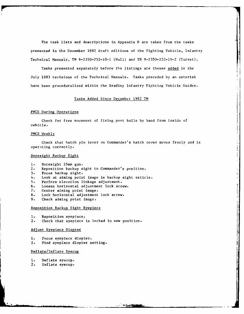
The task lists and descriptions in Appendix D are taken from the tasks
presented in the December 1982 draft editions of the Fighting Vehicle, Infantry
Technical Manuals, TM 9-2350-252-10-1 (Hull) and TM 9-2350-252-10-2 (Turret).
Tasks presented separately before the listings are thoses added in the
July 1983 revisions of the Technical Manuals. Tasks preceded by an asterisk
have been proceduralized within the Bradley Infantry Fighting Vehicle Guides.
Tasks Added Since December 1982 TM
PMCS During Operations
Check for free movement of firing port balls by hand from inside ofvehicle.
PMCS Weekly
Check that hatch pin lever on Commander's hatch cover moves freely and isoperating correctly.
Boresight Backup Sight
I. Boresight 25mm gun.2. Reposition backup sight to Commander's position.
3. Focus backup sight.4. Look at aiming point image in backup sight reticle.5. Perform elevation linkage adjustment.6. Loosen horizontal adjustment lock screw.7. Center aiming point image.8. Lock horizontal adjustment lock screw.9. Check aiming point image.
Reposition Backup Sight Eyepiece
1. Reposition eyepiece.2. Check that eyepiece is locked in new position.
Adjust Eyepiece Diopter
I. Focus eyepiece diopter.2. Find eyepiece diopter setting.
Deflate/Inflate Eyecup
1. Deflate eyecup.2. Inflate eyecup.

PREVENTIVE MAINTENANCE CHECKS AND SERVICES - HULLPMCS Before Operations Checks
Suspension system
1. Check road wheel, idler wheel, and support roller oil levels through sightglasses.
2. Check road wheel, idler wheel, and support roller sight glasses for cracksand breaks.
3. Check road wheels, idler wheels, support rollers, shock absorbers, andtrack shoes for signs of oil leaks.
Vehicle exterior
4. Check outside of vehicle for signs of fuel or oil leaks.
External fire suppression handles
5. Check wires and lead seals on external fire extinguisher handles.
Final drive hull drain plugs
6. Check right and left final drive hull drain plugs.
Driver's hatch
7. Check that driver's hatch can open and close fully and locks in both OPENand CLOSED positions.
8. Check that safety pin is not missing.
Internal fire suppression handles
9. Check that FIRE SUPPRESSION switch is in AUTO.
10. Check wire and lead seal on internal fire suppression handle.
Hull drain plugs
11. Check for open or missing front hull drain plug.
12. Check for open or missing rear hull drain plug.
Internal fire extinguishers
13. Check seals on portable fire extinguishers.
14. Check that pressure gage on both squad area fire extinguishers readwithin 50 psig of correct pressure reading.
15. Check pressure gage on engine compartment fire extinguisher.
.,.,

PREVENTIVE MAINTENANCE CHECKS AND SERVICES - HULL
PMCS During Operations Checks
Driver's seat
16. Check driver's seat adjustment.
Driver's hatch
17. Check that driver's hatch can open and close fully and locks in both OPEN
and CLOSED positions.
18. Check that safety pin is not missing.
Driver's instrument panel
19. Check VOLTS gage.
20. Check ENGINE COOLANT TEMP gage.
21. Check ENGINE OIL gage.
22. Check COOLANT LOW LEVEL warning light.
23. Check TRANS OIL PRESS warning light.
24. Check TRANS OIL TEMP warning light.
25. Check AIR CLEANER CLOGGED warning light.
Driver's periscope
26. Check periscope lenses for dust and cracks.
27. Check blackout covers for tears.
28. Check that blackout covers stay in place when closed.
Ramp
29. Check ramp operation.
Personnel heater
30. Check squad area duct outlet for steady heat output.
31. Have gunner check around personnel heater for smoke or strong diesel
fumes.
32. Have gunner check fuel lines, fittings, and personnel heater for fuel
leaks. Have gunner make check through turret door opening.
2

PREVENTIVE MAINTENANCE CHECKS AND SERVICES - HULL
PMCS During Operations Checks
Squad seats
33. Check that squad seats are secured by locking pins.
34. Check that lap safety belts adjust and release easily.
Cargo hatch
35. Check that release latch releases cargo hatch cover easily and locks in
closed position.
36. Check that hinge position handle locks cargo hatch cover in POP-UP,
TOW LOAD, UPRIGHT, FULL OPEN positions with latch pin fully insertedinto index gear.
Squad area periscopes
37. Check periscope lenses for dust and cracks.
38. Check blackout cover for tears.
39. Check that blackout covers stay in place when closed.
Driver's controls
40. Check accelerator pedal operation.
41. Check gear selector operation.
42. Check steering yoke operation.
43. Check vehicle brakes.
3

PREVENTIVE MAINTENANCE CHECKS AND SERVICES - HULL
PMCS After Operations Checks
Fuel gage
44. Check fuel gage.
Power unit access door
45. Check that door brace holds power unit access door open.
Transmission
46. Check transmission oil level.
47. Check and reset transmission oil filter indicator.
Cooling system
48. Check cooling system hoses for leaks.
49. Check engine coolant level; add as needed.
50. Check bilge area for coolant.
51. Check right angle fan drive for leaks.
Intake screen
52. Check intake screen for debris or damage.
Fuel filter
53. Check that fuel filter is drained until raw fuel come out.
54. Check drained liquid for grit, dust and metal particles.
Final drives
55. Check oil level in left and right final drives.
Engine compartment
56. Check hoses, clamps, fittings for oil and coolant leaks.
57. Check engine oil level.
Suspension
58. Ch -k for m~ssing, broken, or leaking shock absorbers.
59. Check for missing or damaged road wheels, idler wheels, and support
rollers.
4

PREVENTIVE MAINTENANCE CHECKS AND SERVICES - HULL
PMCS After Operations Checks
60. Check for worn mounting holes by looking for shiny area around nuts
and washers.
61. Check all hubs for any large temperature differences.
62. Check road wheel, idler wheel, and support roller oil through sight
glasses.
63. Check track tension.
64. Check track adjuster, grease fitting, and bleed valve for leaks.
65. Check for missing track pin nuts and cracked, bent, or broken track
guides.
5

PREVENTIVE MAINTENANCE CHECKS AND SERVICES - HULL
PMCS Weekly
Torsion bars
66. Check road wheels 1-6 on both sides of vehicle for broken torsion bars.
Batteries
67. Check batteries.
Ramp hydraulic power unit
68. Check ramp hydraulic power unit.
Trim vane
69. Check trim vane for damaged parts or broken mesh.
70. Check that trim vane latch holds trim vane securely in stored position.
PMCS Monthly
Suspension system
71. Check road wheels and support rollers for loss of rubber, pitting,separation of rubber from metal backing, and chunking.
72. Check for broken or bent road and idler wheel arms.
73. Check for worn or missing track shoe pads.
74. Check drive sprocket teeth for wear.
75. Check drive sprocket teeth for breaks and cracks.
76. Check track shoes for breaks and cracks.
77. Check that track pin nuts are centered.
Right angle fan drive
78. Check right angle fan drive oil level.
79. Check that all exterior vehicle lights operate correctly and are not
damaged.
Bilge pumps
80. Check bilge pump operation.
6

PREVENTIVE MAINTENANCE CHECKS AND SERVICES - HULL
PMCS Monthly
Cooling system
81. Check for worn, cracked, or missing coolant pump belt.
82. Check that coolant pump belt does not slip on pulleys.
Firing ports
83. Check that firing port plugs are secure when installed.
84. Check firing port hoses and brass catcher bags for cracks or severe
wear.
85. Check that air flows out of firing port hoses and that gun port vent
fan indicator lights are on.
86. Check that dust covers open and close smoothly when firing port vent
lever is pulled up and down.
Portable fire extinguishers
87. Check tags on both portable fire extinguishers.

HULL MAINTENANCE PROCEDURES
Raise/inspect/lower intake screen
Patch water barrier
Adjust track tension
Remove/install track
A. Remove
B. Install
Remove track shoe from stretched track
Replace track shoe
Break/join track
A. Break track
B. Join track
Remove/install track shoe pads
A. RemoveB. Install
Replace track adjuster grease fitting
Service final drive
Check vehicle batteries
Service bilge pumps
A. Right front bilge pump.B. Left front bilge pump.
C. Right rear bilge pump.D. Left rear bilge pump.E. Bilge pumps power check.
Check/fill radiator
Check/add engine oil
Check/add transmission oil
Check ramp hydraulic power unit
8

PREVENTIVE MAINTENANCE CHECKS AND SERVICE - TURRET
PMCS Before Operations
Turret exterior
1. Check area outside of turret for objects that will block traversing
turret.
2. Check that front ring sight is clean and not damaged.
3. Check TOW launcher for dents and other external damage.
4. Check for debris and damage inside TOW launcher tubes.
5. Check dust cover for tears.
6. Check antenna amounts for damage to antenna support bases and contact
points.
7. Check smoke grenade launcher rubber caps for damage.
8. Check smoke grenade launchers for debris and damage.
9. Check smoke grenade storage bins for debris and damage.
Turrent shield door
10. Check that turret shield door locks in closed position.
Turret interior
11. Check turret interior for objects that should not be there.
12. Check that turret travel lock is not damaged or broken, and make sure thatit engages.
13. Have helper check HE ammo can door to see that it opens, closes, latches.
14. Have helper check AP ammo can door to see that it opens, closes, latches.15. Adjust commander's seat.
16. Check that commander's hatch cover can be locked in open or closed position.
17. Check commander's 8 periscopes and gunner's 2 periscopes for dirty or
cracked periscope lenses.
18. Check that blackout covers are not torn and stay in place when fastened.
19. Check that gunner's seat can be moved freely and locked in raised and
lowered positions.20. Check that gunner's hatch cover can be locked in OPEN or CLOSED position.
21. Check that ballistic sight cover doors open and close smoothly.
22. Have helper check to see if ISU windows are dirty or broken.
25mm gun system
23. Check gun can, zippers, and bolt position indicator for dirt and damage.
24. Check gun power cable on 25mm gun for damage.
25. Check cable plug for dirt, corrosion, damage.26. Check AP and HE feed chutes for damage.
27. Check AP and HE eject chutes for damage.
28. Check 25mm gun for damage.
Coas machinegun
29. Check that handles secure coax machinegun access doors in closed position.
30. Check seals on coax machinegun access doors for damages.
31. Check 7.62 ammo feed chute and two latches for damage.
32. Check rear gun mount.
9

PREVENTIVE MAINTENANCE CHECKS AND SERVICE - TURRETPMCS Before Operations
Turret manual operation
33. Check operation of gun elevation drive select lever and gun elevation handwheel.
34. Check operation of turret traverse drive select lever and turret traversehand wheel.
Communications equipment and intercom
35. Check radio system.36. Check intercom system to make sure commander, gunner, and driver can
communicate.
10

PREVENTIVE MAINTENANCE CHECKS AND SERVICE - TURRET
PMCS During Operations
*ISU cool down
37. Check that mirror control knob is in unlocked position and that quickrelease pin is installed.
38. Check that turret power indicator light goes on.39. Check that closed cycle cooler is operating and can be heard.
NIGHT VISION PWR switch is ON.
Indicator lights and gun fans
40. Check that all lights on weapon control box are on.41. Check that all lights on turret position indicator at gunner's station are
on.42. Check that all lights on TOW control box are on.43. Check that all lights on turret control box go on.44. Check that gun fans are operating and can be heard.
Turret power operation
45. Check that turret drive system indicator light is on.
Commander's control handle
46. Check that turret traverses to right and to left.47. Check that turret traverses at a fast speed to left and then to right.48. Check that 25mm gun elevates and depresses.
Gunner's control handle
49. Check that turret traverses to right and to left.50. Check that turret traverses at a fast speed to left and then to right.51. Check that 25mm gun elevates and depresses.
*Deck clearance system
52. Check that OPEN HATCH annunciator light on annunciator box is on.53. Check that 25mm gun elevates and depresses by itself when passing over
rear deck.54. With driver's hatch cover in UPRIGHT position, check that turret does
not move when gunner's control handles are used.55. With cargo hatch cover in UPRIGHT position, check that turret does not
move when gunner's control handles are used.56. Check that NO FIRE ZONE annunciator light is on.57. Check that NO FIRE ZONE annunciator light is off.
*ISU operation
58. Check that reticle is present in gunner's eyepiece, and that statusindicator reads HE.
59. Check that view through gunner's eyepiece is very much larger than viewthrough unity window.
ii

PREVENTIVE MAINTENANCE CHECKS AND SERVICE - TURRET
PMCS During Operations
60. Check that reticle view in gunner's eyepiece gets darker in NEUTRAL and
brighter in CLEAR.61. Check that reticle in gunner's eyepiece becomes brighter, and then
dimmer.
62. Check that diopter focuses reticle in gunner's eyepiece.
63. Check that diopter focuses reticle in commander's eyepiece.64. Check that lamp behind RANGE control knob is lit.
65. Check that status indicator shows same range setting as on RANGE control
knob.
66. Check that view rises in elevation as range setting increases.67. Check that reticle is present in gunner's eyepiece and that status
indicator reads AP.68. Check that status indicator shows the same range setting as on RANGE
control knob.69. Check that view lowers in elevation as range setting decreases.
70. Check that reticle is present in gunner's eyepiece and that status
indicator reads 7.62.71. Check that status indicator shows the same range setting as on RANGE
control knob.
72. Check that view rises in elevation as range setting increases.
73. Check that night view can be seen through gunner's eyepiece.
74. Check that night view in gunner's eyepiece changes from white-on-red
to black-on-red.
75. Check that BRT and CON knobs adjust brightness and control of view in
gunner's eyepiece.
76. Check that view comes into focus in gunner's eyepiece.
77. Check that view changes from night to day.
, Dry fire operation of 25mm gun
78. Check that manual SAFE handle moves to SAFE position.
79. Check that BOLT position indicator is in SEAR position.
80. Check that drive shaft handle turns.81. Check that SEAR indicator light is on.
82. Check that LO AMMO indicator light flashes.
83. Check that LO AMMO, AP SS, and SEAR indicator lights are on, but not
flashing.
84. Check that bolt position indicator is in MISFIRE position.
85. Check that bolt position indicator is in SEAR position, and that SEAR
indicator light is on.
86. Check dry fire operation of 25mm gun in HE SS mode by repeating step 81and pressing HE SS button instead of AP SS button. Repeat steps 82-85.
87. Check dry fire operation of 25mm gun in AP LO mode by repeating steps
81-85 and pressing AP LO button.
88. Check dry fire operation of 25mm gun in AP HI mode by repeating steps
81-85 and pressing AP HI button.
89. Check dry fire operation of 25mm gun in HE LO mode by repeating steps81-85 and pressing HE LO button.
90. Check dry fire operation of 25mm gun in HE HI mode by repeating steps
81-85 and pressing HE HI button.
91. Repeat steps 79-90. Use commander's handle instead of gunner's control
handles.12

PREVENTIVE MAINTENANCE CHECKS AND SERVICE - TURRETPMCS During Operations
*Dry fire operation of coax machinegun
92. Check that manual safety moves down into fire position.93. Check that charger handle moves smoothly and charges coax machinegun.94. Check that coax machinegun access doors can be closed and latched securely.95. Check that ARM indicator light comes on.96. Check that 7.62 indicator light comes on.97. Check that LO AMMO indicator light flashes.98. Check that LO AMMO indicator light stays on but stops flashing.99. Check that coax machinegun has dry fired.100. Repeat step 99 with commander's handle.
*Smoke grenade launcher operation
101. Check that GRENADE LAUNCHER indicator light comes on.102. Check that TRIGGER indicator light comes on when TRIGGER button is
pressed.
*TOW launcher operation
103. Check that TOW indicator light comes on and stays on.104. Check that TOW test indicator light comes on and then goes off after 12
seconds.105. Check that TRCKR, CGE, and PWR SUP annunciator lights stay off.106. Check that annunciator lights on annunciator box stay off.107. Check that reticle is present in gunner's eyepiece.108. Check that status indicator reads TOW.109. Check that MISSLE TUBE 1 and MISSLE TUBE 2 indicator lights flash when
MISSILE TUBE I and MISSILE TUBE 2 buttons are pressed.110. Check that TOW indicator light goes off.I11. Check that TOW launcher bangs against side of turret and LAUNCHER UP
indicator light goes off.
*Stabilization controls
112. Check that STAB indicator light is on.113. Check to see if center ring of reticle moves more than I mil away from
point aimed at on target within 10 seconds.114. Repeat step 113 for movement of the center ring of reticle away from
aiming point of target.
13
I

PREVENTIVE MAINTENANCE CHECKS AND SERVICE - TURRET
PMCS After Operations
25mm gun
115. Clean, inspect, and lubricate 25mm gun.
Coax machinegun
116. Clean, inspect, and lubricate coax machinegun.
Smoke grenade launcher
117. Clean and inspect smoke grenade launcher.
TOW missile launcher
118. Clean and inspect TOW launcher.
PMCS Weekly
Turret emergency batteries
119. Check turret emergency batteries.
25mm gun
120. Clean, inspect, and lubricate 25mm gun.
Coax machinegun
121. Clean, inspect, and lubricate coax machinegun.
TOW missile launcher
122. Clean and inspect TOW launcher.
Smoke grenade launcher
123. Clean and inspect smoke grenade launcher.
Commander's hatch cover cushioning pad
124. Check cushioning pad on commander's hatch cover for cracks and missing
pieces.
Gunner's hatch cover cushioning pad
125. Check cushioning pad on gunner's hatch cover for cracks and missing
pieces.
14

TURRET MAINTENANCE PROCEDURES
Remove 25mm gun feeder
Remove 25mm gun barrel
Remove 25mm gun receiver
Remove track and bolt assembly
Disassemble track and bolt assembly
Clean/inspect/lubricate 25mm gun
A. Clean 25mm gun feeder
B. Inspect 25mm gun feeder
C. Lubricate 25mm gun feederD. Clean 25mm gun barrel
E. Inspect 25mm gun barrelF. Lubricate 25mm gun barrel
G. Clean 25mm gun receiverH. Inspect 25,m. gun receiver
I. Lubricate 25mm gun receiver
J. Clean track and bolt assembly
K. Inspect track and bolt assembly
L. Lubricate track and bolt assembly
Assemble track and bolt assembly
A. Assemble bolt and bolt carrier
B. Assemble track and bolt assembly
Install track and bolt assembly
Install 25mm gun receiver
Install 25mm gun barrel
Install 25mm gun feeder
Remove coax machinegun
Clean/lubricate coax machinegun
Install coax machinegun
Clean ISU
Clean/inspect TOW launcher
Clean/inspect smoke grenade launcher
15

TURRET MAINTENANCE PROCEDURES
Remove ring sight assembly
Clean front ring sight
Install ring sight assembly
Replace antenna mount
Check turret emergency batteries
16

TASK INDEX: OPERATION UNDER USUAL CONDITIONS - HULL
Stow/unstow squad seats
Operate intercom system
1. Plug in CVC helmet in driver's compartment.
2. Plug in CVC helmet in squad area.
3. Plug in CVC helmet.
4. Select channel on intercom control box.5. Move helmet switch on left of CVC helmet to rear.6. Adjust volume knob on intercom control box.7. Press driver's intercom switch on steering yoke to talk, release switch to
listen.
*Start engine above +40 F (+40 C)
i. Check power unit access panels.2. Adjust brake pedal to desired height.
3. Fasten lap safety belt.
4. Put on and plug in CVC helmet.
5. Check that FIRE SUPPRESSION switch is in AUTO.
6. Move MASTER POWER switch to ON.
7. Move ENGINE ACCESSORY switch to ON.8. Check driver's instrument panel.
9. Turn on fuel control.
10. Sound horn.11. Move gear selector to START and hold until engine starts.
12. Check driver's instrument panel.
22. Release hand brake.
*Start engine below +400 F (+40 C)
1. Check power unit access panels.
2. Adjust brake pedal to desired height.
3. Fasten lap safety belt.
4. Put on and plug in CVC helmet.5. Check that FIRE SUPPRESSION switch is in AUTO.6. Move MASTER POWER switch to ON.
7. Move ENGINE ACCESSORY switch to ON.
8. Check driver's instrument panel.9. Turn on fuel control.
10. Sound horn.
ii. Move gear selector to START and hold until engine starts.12. Check driver's instrument panel.
13. Move COLD START switch to ON.
14. Sound horn.15. Move STARTER CUTOUT OVERRIDE switch to ON.16. Press down accelerator pedal about 1/4 inch.
17. Move gear selector to START and hold until engine starts.
18. Move STARTER CUTOUT OVERRIDE switch to OFF.19. Move COLDSTART switch to OFF.
20. Check driver's instrument panel.
21. Fast idle engine.
22. Release hand brake.17
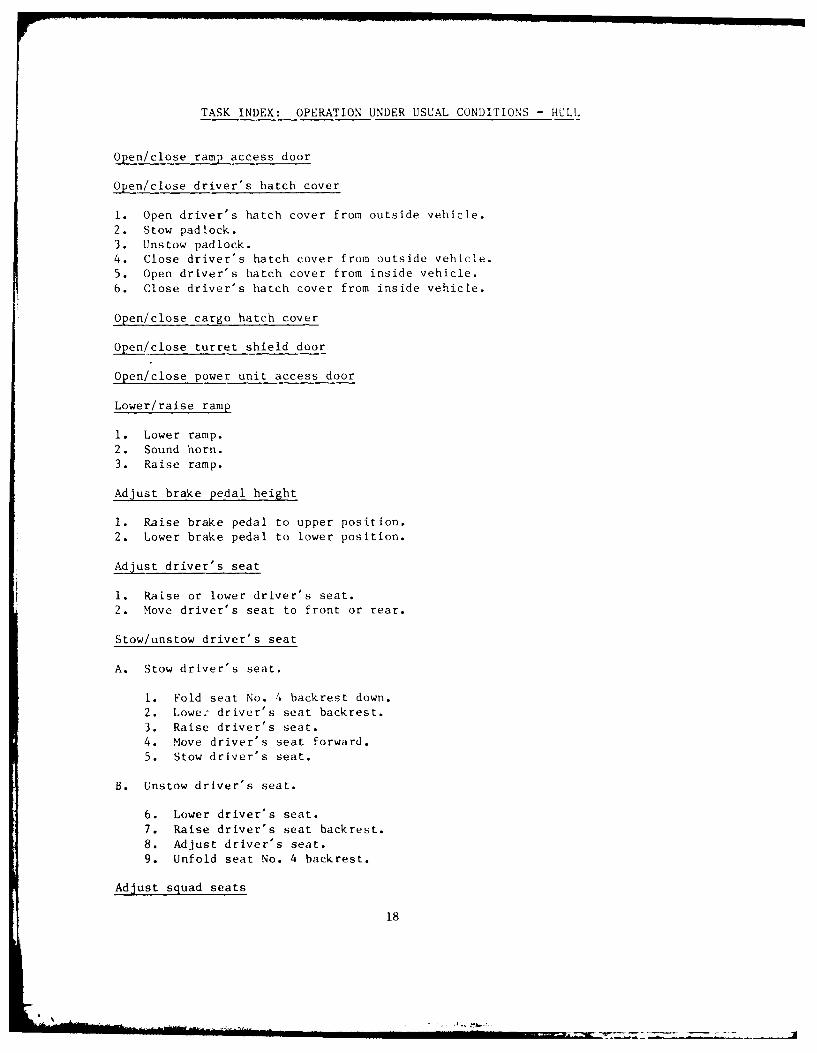
TASK INDEX: OPERATION UNDER USUAL CONDITIONS - HULL
Open/close ramp access door
Open/close driver's hatch cover
1. Open driver's hatch cover from outside vehicle.
2. Stow padlock.
3. Unstow padlock.4. Close driver's hatch cover from outside vehicle.
5. Open driver's hatch cover from inside vehicle.
6. Close driver's hatch cover from inside vehicle.
Open/close cargo hatch cover
Open/close turret shield door
Open/close power unit access door
Lower/raise ramp
1. Lower ramp.
2. Sound horn.
3. Raise ramp.
Adjust brake pedal height
1. Raise brake pedal to upper position.
2. Lower brake pedal to lower position.
Adjust driver's seat
1. Raise or lower driver's seat.
2. Move driver's seat to front or rear.
Stow/unstow driver's seat
A. Stow driver's seat.
1. Fold seat No. 4 backrest down.
2. Lowe: driver's seat backrest.
3. Raise driver's seat.
4. Move driver's seat forward.
5. Stow driver's seat.
B. Unstow driver's seat.
6. Lower driver's seat.
7. Raise driver's seat backrest.
8. Adjust driver's seat.
9. Unfold seat No. 4 backrest.
Adjust squad seats
18

II
TASK INDEX: OPERATION UNDER USUAL CONDITIONS - HULL
*.Start engine with outside power source
1. Check that MASTER POWER switch is OFF.
2. Check that ENGINE ACCESSORY switch is OFF.
3. Check that FIRE SUPPRESSION switch is in ,1ANUAL.4. Check that STARTER CUTOUT OVERRIDE switch is OFF.
5. Check that FWD and REAR BILGE pumps switches are OFF.
6. Check that smoke screen generator switch is OFF.
7. Check that COLD START switch is OFF.
8. Install slave cable.
9. Start engine of operitional vehicle.10. Check that MASTER POk,;.R switch is OFF in disabled vehicle.
11. Move ENGINE ACCESSORY swiLch to ON ia disabled vehicle.
12. Check slave receptacle power light in operati-mial vehicle and disabledvehicle.
13. Turn on fuel control in disabled vehicle.
14. Move gear selector to START and hold until engine starts.15. Remove slave cable.
16. Move MASTER SWITCH to ON in disabled vehicle.
17. When engine starts, check driver's instrument panel.
* Drive vehicle
i. Set gear selector.
2. Sound horn.
3. Move vehicle and control speed.
4. Steer vehicle in forward range.5. Steer vehicle in reverse.6. Pivot steer vehicle.
7. Stop vehicle.
*Stop engine
1. Set hand brake.
2. Turn off fuel control.
3. Move ENGINE ACCESSORY switch to OFF.
4. Move MASTER POWER switch to OFF.
* Shut down vehicle
I. Check that fire suppression switch is in AUTO.
2. Remove brass catcher bag.
3. Clear firing port weapon.
4. Remove firing port weapon.
5. Install firing port plug.6. Close ramp firing port covers.
7. Remove firing port weapons from vehicle.8. Move MASTER POWER switch to ON.
9. Close cargo hatch cover.
10. Lower ramp.
11. Tell crew to exit vehicle.
12. Sound horn.13. Raise ramp.
19

TASK INDEX: OPERATION UNDER USUAL CONDITIONS - HULL
14. Move MASTER POWER switch to OFF.
15. Unstow padlock.
16. Close driver's hatch cover from outside vehicle.
Fuel vehicle
1. Ground vehicle.
2. Release fuel filler combat loclk from inside vehicle.
3. Open fuel filler cover.
4. Clear fuel filler area.
5. Check fuel filler neck screen.
6. Fuel vehicle.
7. Install fuel filler cap.8. Close fuel filler cover.
9. Remove fueling vehicle ground wire.
10. Engage fuel filler combat lock.
Install/remove windshield kit
I. Open driver's hatch cover to fully OPEN position.
2. Unstow windshield kit.
3. Install windshield kit.
4. Remove windshield kit.
5. Stow windshield kit.6. Close driver's hatch cover.
*Operate personnel heater
I. Turn personnel heater on.2. Select HI or LO heat.
3. Turn personnel heater off.
Operate vent system
Operate vehicle lights
I. Operate headlights.2. Operate blackout marker.
3. Operate blackout marker and driving lights.
4. Operate stop light.
5. Operate panel lights.6. Operate parking lights.
7. Operate right turn signal.8. Operate right hazard signal.
9. Operate left turn signal.
10. Operate left hazard signal.
11. Cancel turn or hazard signals.
12. Operate white dome lights.
13. Operate black dome lights.
Operate fire suppression system
1. Operate engine compartment fire extinguisher.20

TASK INDEX: OPERATION UNDER USUAL CONDITIONS - HULL
2. Operate portable :ire extinguishers.
3. Operate fixed fire suppression system from inside of vehicle.
4. Operate engine compartment fire extinguisher from outside of vehicle.
5. Operate fixed fire suppression from outside vehicle.
Install/remove driver's night viewer
A. Install
1. Remove driver's periscope from driver's hatch cover.
2. Unstow driver's night viewer.
3. Set two latch handlers in OPEN position.4. Remove entrance window cover and eyepiece protective cap.5. Install and lock driver's night viewer.
6. Stow driver's periscope.7. Check that battery is removed from driver's night viewer.8. Install vehicle power cable on driver's night viewer.
B. Remove
9. Remove vehicle power cable from driver's night viewer.10. Unlock and remove driver's night viewer from driver's hatch cover.11. Install eyepiece protective cap and entrance window cover.
12. Unstow driver's periscope.
13. Install driver's periscope.
14. Stow driver's night viewer.
*Operate driver's night viewer with vehicle power
1. Check that battery is removed from driver's night viewer.
2. Move MASTER SWITCH to ON.3. Turn OFF/BRIGHT rotary switch to maximum bright position.4. Adjust brightness of driver's night viewer.
5. Position driver's night viewer.
6. Turn OFF/BRIGHT rotary switch to OFF.7. Move MASTER POWER switch to OFF.
*Operate driver's night viewer with battery
8. Check that MASTER POWER switch is OFF.
9. Remove vehicle power cable from driver's night viewer.10. Install battery in driver's night viewer.
11. Turn OFF/BRIGHT rotary switch to maximum bright position.12. Adjust brightness of driver's night viewer.
13. Position driver's night viewer.
14. Turn OFF/BRIGHT rotary switch to OFF.
15. Remove battery from driver's night viewer.
Close/open blackout covers
I. Close blackout covers.
2. Open blackout covers.
21

TASK INDEX: OPERATION UNDER USUAL CONDITIONS - HULL
Stow 25mm ammo
Stow Dragon missiles
Stow TOW missiles
Install firing port weapon
Operate firing port weapon
Remove firing port weapon
Operate smoke screen generator
1. Move smoke screen generator switch to ON.2. Move smoke screen generator to OFF.
Lower/stow trim vane
Remove/install power unit access panels
1. Stow driver's seat.
2. Fold down seat No. 4 backrest.
3. Remove power unit access panels.
4. Install power unit access panels.
5. Raise seat No. 4 backrest.6. Unstow driver's seat.
Raise/lower side armor plates
1. Raise side armor plate.
2. Lower side armor plate.
22

TASK INDEX: OPERATION UNDER USUAL CONDITIONS - TURRET
Operate turret shield door
Operate turret travel lock
1. Set turret travel lock in locked position.2. Move turret traverse lever to manual position.3. Remove spring from handle.
4. Turn turret traverse hand wheel slowly while pushing on travel lock leverto insure that teeth mesh. Release turret traverse hand wheel.
5. Install spring on handle.
6. Move turret traverse drive select lever to power position.7. Release travel lock lever.
Adjust gunner's/commander's seats
1. Raise gunner's or commander's seat.
2. Lower gunner's or commander's seat.
Open/close commander's hatch cover
1. Open commander's hatch cover.
2. Move commander's hatch cover to level position.3. Move commander's hatch cover to upright or full open position.
4. Lock hinge latch handle.5. Unlock hinge latch handle.6. Move commander's hatch cover to pop-up position.
7. Close commander's hatch cover.
Open/close gunner's hatch cover
1. Open gunner's hatch cover.
2. Push gunner's hatch cover back to full open position.3. Lock gunner's hatch cover in full open position.
4. Release gunner's hatch cover from locked position.
5. Close gunner's hatch cover.
*Operate turret in power mode
A. Traverse turret
1. Check that driver's hatch cover is in closed or pop-up position.
2. Check that cargo hatch cover is in closed or pop-up position.3. Close and latch turret shield door.
4. Release turret_ travel lock.5. Put on lap safety bolts.
6. Move turret traverse drive select lever to power position.
7. Move TOW elevation drive select lever to power position.8. Move gun elevation drive select lever to power position.
9. Move TURRET POWER switch to ON.10. Move TURRET DRIVE system switch to ON.
11. Traverse turret.12. Traverse turret at high speed.
23
I

TASK INDEX: OPERATION UNDER USUAL CONDITIONS - TURRET
B. Elevate and depress gun rotor
13. Elevate and depress gun rotor.
14. Elevate and depress gun rotor at high speed.
C. Operate in STAB mode
15. Move STAB switch to ON.
16. Check that drive MALF annunciator lights on turret control and
annunciator boxes are not on.
17. Move STAB switch to OFF.
18. Move TURRET DRIVE system to OFF.
19. Move TURRET POWER switch to OFF.
20. Move ARM-SAFE-RESET switch to RESET then to SAFE.
21. Move TURRET POWER switch to ON.22. Move TURRET DRIVE system switch to ON.
23. Move STAB switch to ON.
24. Check that drive MALF annunciator lights on turret control boxand annunciator box are not on.
25. Press HE SS or AP SS button.
26. Select target through gunner's eyepiece.
27. Aline reticle on target.
28. Press drift button and hold for 3 to 5 seconds.
29. Check for stabilization drift.
(30.) Press drift button and hold for 3 to 5 seconds.
(31.) Check for stabilization drift.
32. Fire 25mm gun as required.
33. Fire Coax machinegun as required.34. Move STAB switch to OFF.35. Traverse TURRET DRIVE system switch to OFF.
36. Move TURRET DRIVE system switch to OFF.
37. Move TURRET POWER switch to OFF.38. Set travel lock.
39. Release lap safety belts.
40. Open turret shield door.
Operate 25mm gun guard and gun cover
1. Remove 25mm gun guard.
2. Open gun cover.3. Close gun cover.
4. Install 25mm gun guard.
Operate coax machinegun access doors
1. Open coax machinegun access doors.2. Close coax machinegun access doors.
24
- - I

TASK INDEX: OPERATION UNDER USUAL CONDITIONS - TURRET
Operate intercom system
1. Plug in CVC helmet.2. Put on CVC helmet.3. Select channel on intercom control box.4. Move helmet switch on left of helmet to rear to talk and listen.5. Adjust volume knob on intercom control box.6. Have gunner press floor switch to talk, release floor switch to listen.
Close/open blackout cover
1. Close blackout cover.2. Open blackout cover.
Operate turret lights
A. Operate service light
1. Remove 25mm gun guard and open gun cover.2. Pull service light from base.3. Push service light on to base.4. Operate service light.5. Pull service light from base, if installed behind 25mm gun guard.6. Push service light onto base.7. Install 25mm gun guard and close gun cover.
B. Operate utility light
8. Remove 25mm gun guard and open gun cover.9. Pull utility light from base.
10. Push utility light onto base.11. Operate utility light.12. Pull utility light from base, if installed behind 25mm gun guard.13. Push utility light onto base.14. Install 25mm gun guard and close gun cover.
C. Operate dome lights
15. Operate white dome lights.16. Operate blackout dome lights.
*Boresight weapons system
A. Boresight 25mm gun
1. Start engine.2. Drive vehicle to within 3200 feet (1000 meters) of suitable target and
position vehicle facing target.3. Stop engine.4. Move TURRET POWER switch to ON.5. Move NIGHT VISION POWER switch to ON.6. Raise ballistic sight cover doors.
25

TASK INDEX: OPERATION UNDER USUAL CONDITIONS - TURRET
7. Move range control knob to 0.
8. Move MAG switch to HIGH.
9. Move SENSOR SELECT switch to CLEAR or NEUTRAL.
10. Press AP SS button.
11. Check that AP appears on status indicator.
12. Move turret traverse drive select lever to manual position.
13. Move gun elevation drive select lever to manual position.
14. Move TOW elevation drive select lever to power position.15. Center gun reticle on aiming point of target.
16. Install 25mm boresight adapter and boresight telescope.17. Focus boresight telescope on target.
18. Release turret travel lock.
19. Aline elevation crosshairs in boresight reticle on aiming point of
target.20. Aline azimuth crosshairs in boresight reticle on aiming point of
target.
21. Check accuracy of boresight telescope.
22. Turn diopter to focus gun reticle.
23. Check alinement of gun reticle on aiming point of target.24. Aline gun reticle on aiming point of target.
25. Remove boresight telescope and 25mm boresight adapter from 29..:1
barrel.
B. Boresight coax machinegun
26. Press 7.62 button.
27. Check that 7.62 appears in status indicator.
28. Check alinement of gun reticle on aiming point of target.
29. Sit in commander's seat.
30. Install boresight adapter and boresight telescope.
31. Focus boresight telescope on target.
32. Open coax machinegun access doors.33. Aline azimuth crosshairs of boresight reticle on aiming point of
target.
34. Aline elevation crosshairs in boresight reticle on aiming point of
target.
35. Remove boresight telescope and boresight adapter.
36. Close coax machinegun access doors.
C. Boresight night sight to day sight using convenient target method.
37. Check that NIGHT VISION POWER switch is ON.
38. Move SENSOR SELECT switch to NIGHT.
39. Turn BRT knob to adjust brightness.40. Turn CON knob to adjust contrast.
41. Turn focus knob to focus gun reticle.42. Aline elevation crosshairs and azimuth crosshairs in gun reticle on
aiming point of target.
43. Move SENSOR SELECT switch to CLEAR or NEUTRAL.
44. Check alinement of gun reticle on aiming point of target.
26

TASK INDEX: OPERATION UNDER USUAL CONDITIONS - TURRET
D. Boresight night sight to day sight using buddy boresight method
45. Start engines of two vehicles.46. Drive two vehicles to level ground and position the two vehicles
facing each other, no less than 656 feet (200 meters) apart.47. Stop engines of two vehicles.48. Move TURRET POWER switches in both vehicles to ON.49. Move NIGHT VISION PWR switches in both vehicles to ON.50. Press AP SS button.51. Check that AP appears on status indicator.52. Turn diopter to focus gun reticle.53. Move night vision PWR switch to BRSIT.54. Aline elevation crosshairs in gun reticle on boresight lamp of other
vehicle.
55. Aline azimuth crosshairs in gun reticle on boresight lamp of othervehicle.
56. Move SENSOR SELECT switch to NIGHT.57. Turn BRT knob to adjust brightness.58. Turn CON knob to adjust contrast.59. Turn focus knob to focus reticle.60. Check alinement of gun reticle on thermal resistor of other vehicle.61. Aline elevation crosshairs and azimuth crosshairs in gun reticle on
thermal resistor of other vehicle.62. Move SENSOR SELECT switch to CLEAR or NEUTRAL.63. Check alinement of gun reticle on boresight lamp of other vehicle.64. Move NIGHT VISION PWR switch to OFF.
E. Boresight TOW launcher
65. Select a suitable target 3280 feet (1000 meters) away from you.Repeat steps 1-5.
66. Move MAG switch to HIGH.67. Move SENSOR SELECT switch to CLEAR or NEUTRAL.68. Raise TOW launcher.69. Move TURRET DRIVE system switch to OFF.70. Press TOW button.71. Check that TOW indicator light stays on when TOW test indicator light
goes out.72. Check that TOW appears on status indicator.73. Move TOW elevation drive select lever to manual position.74. Move gun elevation drive select lever to PWR position.75. Move turret traverse drive select lever to manual position.76. Install boresight telescope.
77. Release turret travel lock.78. Focus boresight telescope on target.79. Look in eyepiece of boresight telescope and aline azimuth crosshair
in boresight reticle on aiming point of target.80. Aline elevation crosshair in boresight reticle on aiming point of
target.81. Check alinement of TOW vehicle on aiming point of target.82. Aline elevation crosshair in TOW vehicle on aiming point of target.
27

TASK INDEX: OPERATION UNDER USUAL CONDITIUNS - TURRET
83. Press TOW button.84. Remove boresight telescope.85. Lower TOW launcher.
86. Move TURRET DRIVE system switch to OFF.
*Zero ISU and 25mm gun
i. Select target that is 1000 meters (3280 feet) away from you.
2. Turn range control knob to 10.3. Move MAG switch to HIGH.
4. Press AP SS button or HE SS button (TP-T only).
5. Traverse turret and elevate or depress 25mm gun to aline reticle ontarget.
6. Move ARM-SAFE-RESET switch to ARM.
7. Fire one round at target.8. Look at strike of round through gunner's eyepiece.
9. Aline reticle on center of strike of round.
10. Traverse turret and elevate or depress 25mm gun to aline reticle back on
target.II. Repeat steps 7 and 8 until 25mm gun is zeroed.
12. Notify organizational maintenance if 25mm gun cannot be zeroed.
* Zero ISU and coax machinegun
1. Choose target 800 meters (2624 feet) from vehicle.
2. Turn range control knob to 8.
3. Move MAG switch to HIGH.
4. Open coax machinegun access doors.
5. Check position of manual safety on coax machinegun.6. Charge coax machinegun.
7. Close coax machinegun access doors.8. Press 7.62 button.
9. Traverse turret and elevate or depress gun rotor to aline reticle or
center of target.
10. Move ARM-SAFE-RESET switch to ARM.11. Fire short burst from coax machinegun.
12. Examine strike of rounds on target.
13. Open coax machinegun access door.14. Turn EL knob to adjust elevation.
15. Turn AZ knob to .iijust azimuth.16. Close coax machinegun access doors.
17. Check for proper zero of coax machinegun.
18. Open coax machinegun access doors.
19. Push manual safety up to safe position with "S" showiig.
20. Close coax machinegun access door.
Time 25mm gun feeder
1. Turn worm shaft nut.2. Cycle 25mm gun feeder to SEAR position.3. Check bolt position indicator.
28

TASK INDEX: OPERATION UNDER USUAL CONDITIONS - TURRET
*Position 25mm gun bolt in SEAR position
1. Check position of drive shaft handle.2. Pull out drive shaft handle.
3. Lock bolt in SEAR position.4. Release SEAR retractor lever.
5. Check that drive shaft handle will not turn.
6. Install 25mm gun feeder.
, Load 25mm gun feeder
1. Remove 25mm gun guard and open gun cover.
2. Check that bolt position indicator is in SEAR position.
3. Check that manual SAFE handle is in SAFE position.4. Manually elevate 25mm gun to 200 mils.
5. Pull or feed select solenoid knob to HE position.
6. Forward HE AMMO to 25mm feeder.
7. Load feeder with two rounds of HE AMMO.8. Push in FWD select solenoid knob to AP position.9. Forward AP AMMO to 25mm feeder.
10. Load feeder with one round of AP ammo.11. Close gun cover and install 25mm gun guard.
* Load/reload 25mm HE AMMO
1. Traverse turret to HE LOAD position (2150 mils)
2. Set turret travel lock.
3. Move TURRET DRIVE system switch to OFF.
4. Move TURRET POWER switch to OFF.
5. Open turret shield door.
6. Turn handle and remove 25mm ammo can door.
7. Turn handle and remove access door.
8. Turn handle and remove HE AMMO can door.
9. Stow squad seats.
10. Unstow HE AMMO boxes from floor.
11. Stack HE AMMO boxes.
12. Unstow HE AMMO boxes from IFV ammo racks if necessary.
13. Stack HE AMMO boxes. (14-15 CV only)
16. Prepare first ammo belt.
17. Prepare second ammo belt.
18. Remove first round from ammo belt.
19. Join second ammo belt to first ammo belt.
20. Check ammo belt for short rounds.21. Join ammo belts as required.
22. Load first 44 rounds in ammo can.
23. Release upper roller.
24. Forward ammo belt.
25. Lock upper roller.
26. Lock next group of rounds on ammo belt in ammo can.
27. Lift ammo belt loops over baffle.
29

TASK INDEX: OPERATION UNDER USUAL CONDITIONS - TURRET
28. Lift ammo belt loops over roller.
29. Load ammo belt while ammo can is full.
30. Install HE ammo can door and turn handle.
31. Install access door and turn handle.
32. Install 25mm ammo can door and turn handle.
33. Move HE-AP selector to HE.34. Stow empty ammo cans.
35. Close turret shield door.
36. Move TURRET POWER switch to ON.
37. Move TURRET DRIVE system switch to ON.38. Release turret travel lock.
39. Traverse turret to 6400 mils.
40. Tell ommander HE AMMO is loaded.
* Load/reload 25mm AP AMMO
1. Traverse turret to AP load position (4350 mils).
2. Set turret travel lock.
3. Move TURRET DRIVE system switch to OFF.
4. Move TURRET POWER switch to OFF.
5. Open turret shield door.
6. Open and remove AP AMMO can door from AP AMMO can.
7. Stow squad seats.8. Unstow AP AMMO boxes from floor.
9. Stack AP AMMO boxes.
10. Unstow squad seats if necessary.
11. Unstow HE AMMO boxes from IFV ammo racks if necessary.
12. Stack AP AMMO boxes. (13-14 CFV)
15. Prepare first ammo belt.16. Prepare second ammo belt.
17. Remove first round from second ammo belt.
18. Join second ammo belt to first ammo belt.
19. Check ammo belt for short rounds.
20. Join ammo belts as required.21. Load ammo belt onto loading rail.
22. Fcrward ammo belt.
23. Join ammo belt to round hanging from AP feed chute.
24. Install and close AP AMMO can door.
25. Move HE-AP selector switch to tl.
26. Stow empty ammo cans.
27. Close turret shield door.
28. Move TURRET POWER switch to ON.
29. Move TURRET DRIVE system switch to ON.
30. Release turret travel lock.31. Traverse turret to 6400 mils.
32. Tell commander AP AMMO is loaded.
* Fire 25mm gun
I. Move TURRET DRIVE system switch to OFF.
2. Remove 25mm gun guard and open gun cover.
3. Move manual SAFE handle to FIRE position.
30

TASK INDEX: OPERATION UNDER USUAL CONDITIONS - TURRET
4. Close gun cover and install 25mm gun guard.
5. Select ammo as required.
6. Move TURRET DRIVE system switch to ON.
7. Move NIGHT VISION PWR switch to ON.
8. Move SENSOR SELECT switch to NIGHT.9. Move night vision PLRT switch to W/H or B/H as desired.
10. Turn CON knob to adjust control.
11. Turn BRT knob to adjust brightness.
12. Turn FOCUS knob to focus image in gunner's eyepiece.
13. Move SENSOR SELECT switch to CLEAR or NEUTRAL
14. Turn RET BRT knob to adjust reticle brightness.
15. Move MAG switch to light.
16. Find range of target using range finder in reticle.
17. Turn range control knob to range estimated in step 16.18. Center target in reticle.19. Move ARM-SAFE-RESET switch to AR.M.
20. Fire 25mm gun at target.
21. Remove 25mm gun guard.
22. Check bolt position indicator.23. Move AR-M-SAFE-RESET switch to SAFE.
24. Move TURRET DRIVE system switch to OFF.
25. Remove 25mm gun guard and open gun cover.
26. Clear 25mm gun.
27. Move manual SAFE handle to SAFE.
28. Close gun cover and install 25mm gun guard.
, Unload 25mm gun feeder
A. Prepare 25mm gun feeder for unloading
1. Move ARM-SAFE-RESET switch to RESET, then to SAFE.2. Set turret travel lock.
3. Remove 25mm gun guard and open gun cover.
4. Move manual SAFE handle to SAFE position.5. Raise feeder handle.
6. Remove power cable from 25mm gun.
7. Open coax machinegun access doors.8. Disconnect AP and HE links from links in AP and HE eject chotes.
9. Close coax machinegun access door.
10. Remove AP link eject chute from 25mm gun feeder.
11. Pull out feed select solenoid knob to HE position.
B. Unload AP AMMO from 25mm gun feeder
12. Unload AP AMMO from 25mm gun feeder.
13. Remove 25mm gun feeder.
C. Remove HE link eject chute from 25mm gun feeder.
14. Manually depress 25mm gun to maximum depression.
15. Remove HE eject chute from 25mm gun feeder.
16. Push in feed select solenoid knob to AP position.
31
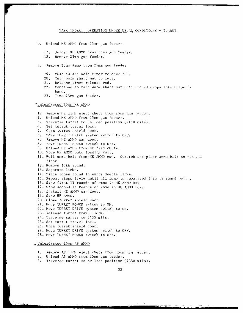
TASK INDEX: OPERATION UNDER USUAL CONDITIONS - TURR T
D. Unload HE AMMO from 25mm gun feeder
17. Unload HE AMMO from 25mm gun feeder.
18. Remove 25mm gun feeder.
E. Remove 25mm Ammo from 25mm gun feeder
19. Push in and hold timer release rod.
20. Turn worm shaft nut to left.
21. Release timer release rod.
22. Continue to turn worm shaft nut until round drops into helplr'
hand.
23. Time 25mm gun feeder.
*Unload/stow 25mm HE AMMO
1. Remove HE link eject chute from 25mm gun feeder.
2. Unload HE AMMO from 25mm gun feeder.
3. Traverse turret to HE load position (2150 mils).
4. Set turret travel lock.
5. Open turret shield door.6. Move TURRET DRIVE system switch to OFF.
7. Remove HE AMMO can door.8. Move TURRET POWER switch to OFF.
9. Unload HE AMMO from HE feed chute.10. Move HE AMMO onto loading rail.
ii. Pull ammo belt from HE AMMO can. Stretch and place am-o belt nfloor.
12. Remove 15th round.
13. Separate links.14. Place loose round in empty double links.
15. Repeat steps 12-14 until all ammo is separated into 15 r nd t16. Stow first 15 rounds of ammo in HE AIMMO box
17. Stow second 15 rounds of ammo in HE AMMO box.
18. Install HE AMMO can door.
19. Stow HE AMMO.
20. Close turret shield door.
21. Move TURRET POWER switch to ON.
22. Move TURRET DRIVE system switch to ON.
23. Release turret travel lock.
24. Traverse turret to 6400 mils.
25. Set turret travel lock.
26. Open turret shield door.
27. Move TURRET DRIVE system switch to OFF.
28. Move TURRET POWER switch to OFF.
* Unload/stow 25mm AP AMMO
1. Remove AP link eject chute from 25mm gun feeder.
2. Unload AP AMMO from 25mm gun feeder.
3. Traverse turret to AP load position (4350 mils).
32

TASK INDEX: OPERATION UNDER USUAL CONDITIONS - TURRET
4. Set turret travel lock.
5. Open turret shield door.6. Move TURRET DRIVE system switch to OFF.
7. Remove AP AMMO can door.8. Move TURRET POWER switch to OFF.
9. Unload AP AMMO from AP feed chute.
10. Remove AP AMMO onto loading rail.
ii. Pull ammo belt fr, AP AMMO can. Stretch and place ammo belt on vehicle
floor.
12. Remove 15th round.13. Separate links.
14. Place loose rounds in empty double links.
15. Repeat steps 12 thru 14 until all ammo is separated into 15 round belts.
16. Stow first 15 rounds of ammo in AP AMMO box.
17. Stow second 15 rounds of ammo in AP AM MO box.18. Install AP A(MMO can door.
19. Stow AP AMMO.20. Close turret shield door.21. Move TURRET POWER switch to ON.
22. Move TURRET DRIVE system switch to ON.
23. Release turret travel lock.
24. Traverse turret to 6400 mils.
25. Set turret travel lock.
26. Open turret shield door.
27. Move TURRET DRIVE system switch to OFF.
28. Move TURRET POWER switch to OFF.
, Load/reload coax machinegun ammo
1. Open coax machinegun door.
2. Open coax machinegun access door.
3. Set manual safety on coax machinegun.
4. Open feed cover and feed tray.5. Inspect chamber for round.
6. Unstow and open four 7.62mm cans.
7. Load ammo belt in first section of coax ammo box.8. Link ammo belts.
9. Load second and third sections of coax ammo box.10. Load top area of coax ammo box.11. Link loaded ammo belt to ammo in chute.12. Close feed tray.
13. Install ammo belt on feed tray.
14. Close feed cover.
15. Close coax machinegun access doors.
16. Close coax ammo box door.
*Fire coax machinegun
1. Open coax machinegun access doors.2. Check position of manual safety on coax machinegun.
3. Charge coax machinegun.
33
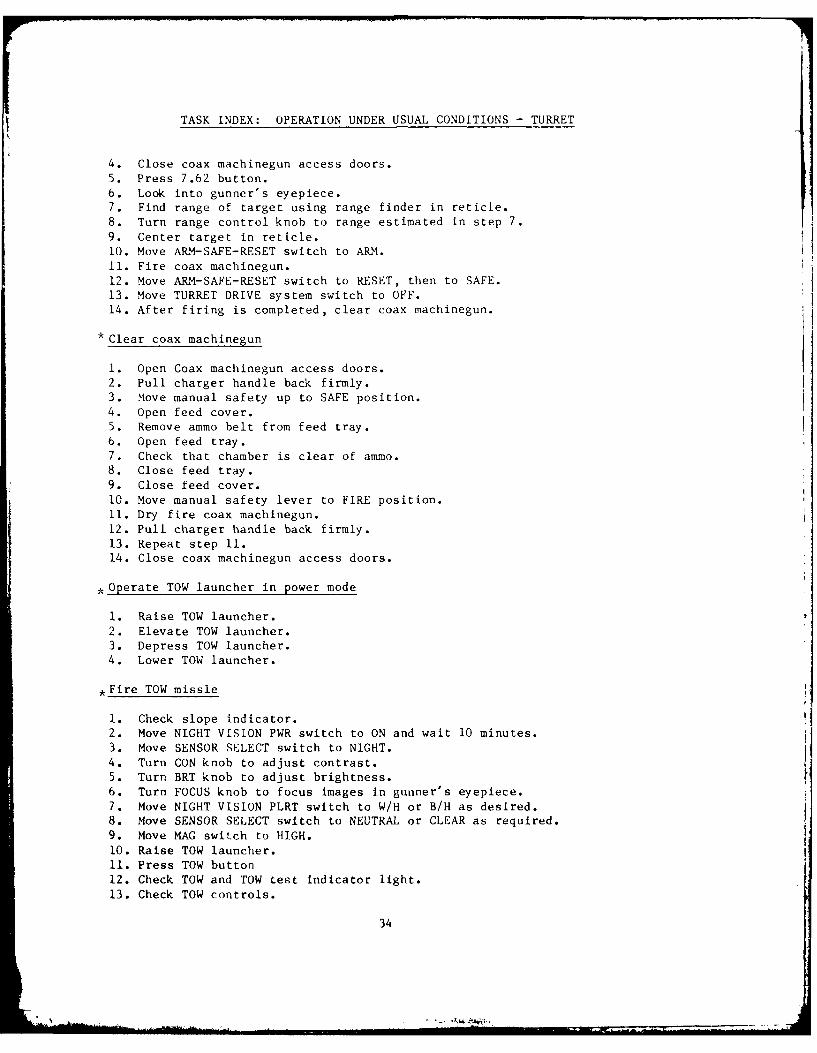
TASK INDEX: OPERATION UNDER USUAL CONDITIONS - TURRET
4. Close coax machinegun access doors.
5. Press 7.62 button.
6. Look into gunner's eyepiece.7. Find range of target using range finder in reticle.
8. Turn range control knob to range estimated in step 7.
9. Center target in reticle.10. Move ARM-SAFE-RESET switch to ARM.
11. Fire coax machinegun.
12. Move AR.M-SAFE-RESET switch to RESET, then to SAFE.
13. Move TURRET DRIVE system switch to OFF.
14. After firing is completed, clear coax machinegun.
* Clear coax machinegun
1. Open Coax machinegun access doors.
2. Pull charger handle back firmly.3. Move manual safety up to SAFE position.
4. Open feed cover.5. Remove ammo belt from feed tray.
6. Open feed tray.
7. Check that chamber is clear of ammo.8. Close feed tray.
9. Close feed cover.
10. Move manual safety lever to FIRE position.
11. Dry fire coax machinegun.12. Pull charger handle back firmly.
13. Repeat step 11.
14. Close coax machinegun access doors.
, Operate TOW launcher in power mode
1. Raise TOW launcher.
2. Elevate TOW launcher.
3. Depress TOW launcher.
4. Lower TOW launcher.
*Fire TOW missle
1. Check slope indicator.
2. Move NIGHT VISLON PWR switch to ON and wait 10 minutes.
3. Move SENSOR SELECT switch to NIGHT.
4. Turn CON knob to adjust contrast.
5. Turn BRT knob to adjust brightness.
6. Turn FOCUS knob to focus images in gunner's eyepiece.
7. Move NIGHT VISION PLRT switch to W/H or B/H as desired.8. Move SENSOR SELECT switch to NEUTRAL or CLEAR as required.
9. Move MAG switch to HIGH.
10. Raise TOW launcher.11. Press TOW button
12. Check TOW and TOW test indicator light.
13. Check TOW controls.
34

TASK INDEX: OPERATION UNDER USUAL CONDITIONS - TURRET
14. Check that annunciator lights on annunciator box are off.
15. Check that annunciator lights on TOW control box are off.
16. Look into gunner's eyepiece.
17. Press button of missile tube 1 or missile tube 2.
18. Move ARM-SAFE-RESET switch to ARM.
19. Center reticle crosshairs on target.
20. Squeeze and hold trigger and palm switches on gunner's control handles.
21. Track target with gunner's control handles until TOW missile impacts.22. Abort TOW missile if required.
23. With gunner's control handle, guide TOW missile to safe area until TOW
missile impacts.
24. Fire second TOW missile. Repeat steps 17 thru 23.
* Unload 7.62mm ammo
1. Open coax ammo box door.
2. Clear coax ammo forwarder.
3. Close coax ammo box door.4. Unstow empty 7.62mm ammo cans.
5. Open empty 7.62mm ammo cans.6. Remove about 100 rounds of 7.62mm ammo from coax ammo box.
7. Stow 100 round belt in 7.62mm ammo can.8. Fill and Jlose 7.62mm ammo can.
9. Unload remaining 7.62mm ammo from coax ammo box and stow in 7.62 ammo
cans.
10. Stow 7.62mm ammo cans.
*Load/reload TOW launcher
1. Traverse turret to TOW load position (5950 mils).
2. Raise TOW launcher.
3. Elevate TOW launcher to 500 mils.
4. Move TURRET DRIVE system switch to OFF.5. Move TURRET POWER switch to OFF.
6. Move MASTER POWER switch to OFF.
7. Set turret travel lock.
8. Open cargo hatch cover to TOW load position.
9. Remove dust cover.
10. Prepare TOW launcher for loading.
11. Remove any obstructions or debris from TOW launcher tubes.
12. Check that umbilical connectors do not extend down into TOW launcher
tubes.
(13.)Withdraw umbilical connectors from row launcher tubes.
(14.)If spent TOW missile casing hangs up in TOW launcher tube, pull down hard
on handles to aline lug channels.(15.)Pull spent TOW missile casing from TOW launcher tube.
(16.)Withdraw umbilical connectors from TOW launcher tubes.
(17.)Discard spent TOW missile casing.
18. Unstow TOW missiles from vertical stowages.
19. Unstow TOW missiles from horizontal stowages (Step 20 CFV only).
35
C
......................... --1 ' '' - "" '

TASK INDEX: OPERATION UNDER USUAL CONDITIONS - TURRET
21. Remove forward handling ring from nose end of TOW missile.
22. Remove electrical connector cover from TOW missile electrical connector.Save cover until TOW missiles are fired.
23. Inspect TOW missile for damages.
24. Lug channels in the TOW launcher can get out of aliement and block TOWmissile loading. If TOW missile meets resistance about halfway into TOW
launcher, pull down hard on loading handle to realine lug channels.25. Load TOW missile into TOW launcher.
26. Close cargo hatch cover. Tell gunner that cargo hatch cover is closed.
27. Move MASTER POWER switch to ON.28. Move TURRET POWER switch to ON.
29. Move TURRET DRIVE system switch to ON.30. Traverse turret to 6400 mils.
31. Lower TOW launcher.
tnload TOW launcher
1. Traverse turret to TOW load position (5950 mils).
2. Raise TOW launcher.
3. Elevate TOW launcher to 500 mils.
4. Move TURRET DRIVE system switch to OFF.
5. Move TURRET POWER switch to OFF.
6. Move MASTER POWER switch to OFF.7. Set turret travel lock.8. Open cargo hatch cover to TOW load position.
9. Inspect rear end of TOW missile for damage.
10. Unload TOW missile from TOW launcher.11. Move MASTER POWER switch to ON.
12. Move TURRET POWER switch to ON.
13. Move ARM-SAFE-RESET switch to RESET, then to SAFE. Wait 10 seconds.14. Move TURRET POWER switch to OF.
15. Move MASTER POWER switch to OFF.16. Unload second TOW missile from TOW launcher. Repeat step 10.
17. Prepare TOW missile for stowage.18. Stow TOW missiles.
19. Install dust cover on TOW launcher.20. Close cargo hatch cover and tell gunner that cargo hatch is closed.
21. Move MASTER POWER switch to ON.22. Move TURRET POWER switch to ON.
23. Move TURRET DRIVE system switch to ON.24. Traverse turret to 6400 mils.
25. Depress TOW launcher to 0 .,,Its.
26. Power TOW launcher.
*Load/stow/reload smoke grenades
A. Load and stow smoke grenades
1. Move TURRET DRIVE system switch to OFF.
2. Move TURRET POWER switch to OFF.
3. Move MASTER POWER switch to OFF.
36
* . . . ... il I' "' = I . . i i, I II' . . . . =

TASK INDEX: OPERATION UNDER USUAL CONDITIONS - TURRET
4. Open right side smoke grenade stowage bin.
5. Remove four rubber caps from right side grenade launcher tubes.
6. Unpack eight smoke grenades from two ammo boxes.
7. Stow four smoke grenades in right side smoke grenade stowage bin.8. Load four smoke grenades in right side grenade launcher tubes.
9. Install four rubber caps on right side grenade launcher tubes.10. Stow four smoke grenades in left side smoke grenade stowage bins.
Load four smoke grenades in left side grenade launcher tubes. Repeat
steps 4-9.
B. Reload smoke grenades
11. Prepare vehicle for reloading smoke grenades. Repeat steps 1-3.
12. Remove four smoke grenades from right side smoke grenade stowage bin.
13. Reload four smoke grenades in right side grenade launcher tubes.
Repeat steps 8 and 9.14. Unstow and reload four smoke grenades in left side grenade launcher
tubes. Repeat steps 12, 8, and 9.
* Launch smoke grenades
1. Close gunner's hatch cover.
2. Close commander's hatch cover.
3. Close cargo hatch cover.4. Close driver's hatch cover.
5. Move GRENADE LAUNCHER switch to ON.
6. Press trigger button to fire smoke grenades.
7. Take immediate action if smoke grenades fail to fire.
8. Move GRENADE LAUNCHER switch to OFF.
9. As soon as tactical situation permits, check that all smoke grenades have
fired.
*Unload/stow smoke grenades
1. Move TURRET DRIVE system switch to OFF.
2. Move TURRET POWER switch to OFF.
3. Unlatch and open right side smoke grenade stowage bin.4. Remove four rubber caps from right side grenade launcher tubes.
5. Remove four smoke grenades from right side grenade launcher tubes.
6. Stow four smoke grenades in right side smoke grenade stowage bin.
7. Install four rubber caps on right side grenade launcher tubes.8. Repeat steps 3 thru 7 to unload and stow smoke grenades on left side of
turret.
* Shut dc-mn turret
1. Elevate and depress gun rotor to 0 mils.
2. Traverse turret to 6400 mils.
3. Set turret travel lock in locked position.
4. Move turret traverse select lever to manual position.
5. Turn turret traverse hand wheel slowly while pushing on travel lock leverto insure that teeth mesh.
37

TASK INDEX: OPERATION UNDER USUAL CONDITIONS - TURRET
6. Move STAB switch to off.7. Move TURRET DRIVE system switch to OFF.8. Move TURRET POWER switch to OFF.9. Close both ballistic sight cover doors.10. Unlock hinge latch handle.I1. Move commander's hatch cover to POP-UP position.12. Close commander's hatch cover.13. Release gunner's hatch cover from locked position.14. Close gunner's hatch cover.15. Move power switch on commander's radio to OFF.16. Move power switch on gunner's radio to OFF.17. Move power CKT BKR switch on intercom amplifier to OFF.18. Open turret shield door.19. Turn two white dome lights off.20. Turn two blackout dome lights off.
38

TASK INDEX: OPERATION UNDER UNUSUAL CONDITIONS - HULL
*Operate in extreme cold: below -25 ° F (-10 ° C)
A. Prepare to operate vehicle in extreme cold.
1. Check that gunner's hatch cover is closed.
2. Check that commander's hatch cover is closed.3. Check that cargo hatch cover is closed.
4. Check that ramp is raised.
5. Check that ramp access door is closed.6. Check that driver's hatch cover is closed.
7. Open turret shield door.
8. Install grille cover.
9. Manually depress 25mm gun.
10. Place tarpaulin over vehicle.
B. Operate vehicle in extreme cold.
11. Fold tarpaulin back over turret to uncover exhaust/intake grills.
12. Operate winterization kit.
13. Cold start engine.14. Release hand brake.
15. Press down brake pedal and hold through step 16.
16. Move gear selector to PIVOT STEER and hold for 5 minutes while slowly
raising engine idle. Raise idle while engine runs smoothly.17. Manually elevate 25mm gun.18. Check engine coolant gauge. Go to steps 19 or 22.
19. Lower engine idle to slow and move gear selector to NEUTRAL.
20. Set hand brake.21. Fold grille cover to partly uncover intake grille.
22. Remove tarpaulin from vehicle.23. Repeat steps 14-16.24. Perform mission. Then park vehicle on high ground in sheltered area,
faced away from wind if possible.25. Fold grille cover to uncover intake grille.
26. Stop engine.27. Lower trim vane.
28. Open power unit access door.
29. Drain fuel filter of water.30. Close power unit access door.
31. Stow trim vane.
32. Install grille cover.
33. Manually depress 25mm gun.24. Place tarpaulin over vehicle.
25. Repeat steps 1- 6.
*Operate winterization kit
1. Fold exhaust grille cover to uncover exhaust grille.
2. Move MASTER SWITCH to ON.
3. Start and operate winterization kit heater.
4. Start personnel heater.
5. Shut down winterization kit heater.
6. Turn personnel heater off.39

TASK INDEX: OPERATION UNDER UNUSUAL CONDITIONS - HULL
* Prepare to enter water
1. Open driver's hatch cover.
2. Open commander's hatch cover.
3. Open gunner's hatch cover.
4. Elevate 25mm gun to 550 mils.
5. Open cargo hatch cover to UPRIGHT position.
6. Lower ramp.
7. Close firing port vents.
8. Check drain plugs.
9. Close front hull drain plug.
10. Close rear hull drain plug.
11. Remove firing port weapons.
12. Remove two front upper hull drain plugs.
13. Remove two rear upper hull drain plugs.
14. Raise ramp.
15. Check ramp for good seal.
16. Check ramp for access door for good seal.
17. Raise exhaust shroud.
18. Erect water barrier.
* Ford water less than 3 1/2 feet deep
1. Close front hull drain plug.
2. Close rear hull drain plug.
3. Check that two final drive hull drain plugs are in place and secured.
4. Check that four upper hull drain plugs are in place and secured.
5. Raise ramp.
6. Start engine.
7. Move FWD and REAR BILGE pumps to ON.
8. Ford water.
9. After bilges empty, move FWD and REAR BILGE pump switches to OFF.
* Erect water barrier
A. Erect tripods
i. Erect left side tripod.
2. Unstow right side tripod.
3. Erect right side tripod.
B. Unstow water barrier
4. Unstow water barrier.
C. Erect rear of water barrier
5. Erect rear of water barrier.
6. Adjust "T" end of tripod.
D. Erect trim vane
7. Erect trim vane.4o
iI

TASK INDEX: OPERATION UNDER UNUSUAL CONDITIONS - HULL
E. Erect sides of water barrier
8. Attach two cable eyelets to trim vane.
9. Pull water barrier over top of trim vane.
10. Raise and lock upper trim vane.
11. Lock trim vane in place.
12. Remove two blocks from right and left brackets.
13. Install two blocks in right and left slides.
14. Install outside elastic cords to grommets on left and right sides of
water barrier.
15. Tie inside elastic cord to lifting eye.
16. Snap end of release lanyard to footman loop.
17. Install bilge pump exhaust pipes in front bilge pump outlets.
18. Put struts into caps on left and right sides of hull.
19. Move MASTER POWER switch to ON.
20. Move FWD and REAR bilge pump switches to ON.
21. Check that air flows out of bilge pump exhaust pipes and rear bilge
pump outlets.22. Move FWD and REAR bilge pump switches to OFF.
23. Move MASTER POWER switch to OFF.
F. Raise ramp
24. Raise metal cover.
25. Raise ramp.
*Drive in water
1. Move FWD and REAR bilge pump switches to ON.
2. Choose spot to enter and exit water.
3. Tell driver where to steer vehicle via intercom.
4. Enter water.
5. Drive vehicle in water.6. Turn vehicle in water.
7. Stop vehicle quickly in water.
8. Reverse vehicle quickly in water.
9. Drive vehicle forward in water after reversing.
10. Turn vehicle quickly in water.
11. Drive vehicle forward in water after turning quickly.
12. Exit water.
i. Perform post-swimming operations.
*Stow water barrier
A. Stow trim vane.
i. Lower ramp.
2. Untie elastic cord from lifting eye.
3. Remove outside elastic cords from left and right sides of water
barrier.4. Remove two bilge pump exhaust pipes from two front bilge pump outlets.
5. Remove wire struts from wire cups on left and right sides of hull.
6. Stow lanyard.41

TASK INDEX: OPERATION UNDER UNUSUAL CONDITIONS - HULL
7. Pull water barrier release lever (under driver's instrument panel)
back to raise trim vane to vertical position.
8. Push water barrier off upper trim vane. Have h._per assist.
9. Remove two cable eyelets from upper trim vane.
10. Fold upper trim vane into locked position.
11. Unfold snaps on water barrier from trim vane.
12. Fold trim vane against hull. Have helper assist.
B. Stow tripods
13. Remove four cable ends of water barrier from two tripods.
14. Stow left side tripod.
15. Remove right side tripod.16. Stow right side tripod.
C. Stow front of water barrier
17. Stow front of water barrier.
D. Stow rear of water barrier
18. Stow rear corners of water barrier.
19. Stow rear of water barrier.
E. Stow sides of water barrier
20. Stow right side of water barrier.
21. Stow left side of water barrier.22. Close cargo hatch cover.
23. Raise ramp.
*Perform post-swiming operations
1. Release upper trim vane.
2. Drive vehicle to trim level ground.
3. Set hand brake and let engine idle.
4. Turn off fuel control.
5. Move ENGINE ACCESSORY switch to OFF.6. Move FWD and REAR bilge pump switches to OFF after water is out of vehicle.
7. Move MASTER POWER switch to OFF.
8. Stow water barrier.9. Drain water from front bilge.10. Drain water from rear bilge.
11. Open firing port vents.
12. Install upper hull drain plugs.13. Check for water in hubcap oil.
14. Check for water in final drive oil.
*Operate vehicle over rough terrain
1. Drive vehicle over trenches.
2. Drive vehicle over obstacle.
3. Drive vehicle on hills.42

TASK INDEX: OPERATION UNDER UNUSUAL CONDITIONS - HULL
4. Drive vehicle on side slopes.
5. Drive vehicle on snow, ice, or mud.
6. Park vehicle on snow, ice, or mud.
*Tow disabled vehicle
A. Install
1. Align rear of towing vehicle with front of disabled vehicle.
B. Connect vehicles with tow bar
2. Remove two pins and shackles from two towing eyes on disabled vehicle.
3. Install tow bar on front of disabled vehicle.4. Install tow bar on pintle of towing vehicle.
C. Connect vehicle with tow vehicle
5. Remove tow cable from disabled vehicle.
6. Remove tow cable from towing vehicle.
7. Remove four pins and shackles from rear of towing vehicle and front of
disabled vehicle.
8. Install two towing cables on front of disabled vehicle and rear of
towing vehicle in an "X" pattern.
D. Prepare to tow disabled vehicle
9. Move disabled vehicle gear selector to TOW and push down to lock.
10. Release disabled vehicle hand brake.
11. Start engine in towing vehicle.
E. Tow disabled vehicle
12. Set towing vehicle gear selector.13. Operate headlights.
14. Sound horn.15. Move vehicle and control speed.
16. Steer vehicle.
17. Stop vehicles.
18. Stop engine in towing vehicle.
F. Disconnect vehicles when using tow bar
19. Disconnect tow bar from pintle of towing vehicle.
20. Disconnect tow b3r from towing eyes of disabled vehicle.
G. Disconnect vehicles when using tow cables
21. Remove tow cables from towing eyes.
43
II- I l I I-II III! I i

TASK INDEX: OPERATI()N I N , , ', , -
*Tow start disabled vehicle
A. Connect vehicles with tow bar
1. Align rear of towing vhi'l, -. 4th : '2. Remove two pins and shackles frw: tw. " 'or o' . ,: *md vt& i -l -e.3. Install tow bar on Cront uf di4. Install tow bar on pintle (t t,>wioi :I.
B. Tow start disabled vehicle
5. Do before (B) preventive maintenance checks ind 'wrvi- .'.6. Move MASTER POWER switch in disabled vehicle to ON.7. Move ENGINE ACCESSORY switch in disabled vehicle to 0'.8. Move fuel control handle in disabled vehicle to (iN.9. Release hand brake.
10. Start towing engine.11. Drive towing vehicle.12. Tow start vehicle.13. When disabled vehicle starts, move vehicle gear selector to DRIVE,
bring both vehicles to a stop, move gear selector to N (NEUTRAL).14. Set hand brake cn both vehicles.15. Check disabled vehicle instrument panel for normal gauge reading
and light indications.16. If engine fails to start within 10 seconds of towing at 10-15 mph
(15-25 km/hr), wait one minute, then repeat steps 9 and 10.17. Stop towing vehicle engine.
C. Disconnect vehicles when using a tow bar
18. Remove tow bar from pintle of towing vehicle.19. Remove tow bar from towing eyes of disabled vehicle.20. Install two pins and shackles in two towing eyes on disabled vehicle.
Gain access to turned turret in an emergency
*Immediate action to stop runaway engine
1. Move gear selector to N (NEUTRAL).2. Turn off fuel control.3. Stop vehicle.4. Set hand brake.5. Traverse turret to 4100 mils.6. Turn off main fuel manual shut-off valve.7. Traverse turret to 6400 mils.8. Notify organizational maintenance.
44

TASK INDEX: OPERATION UNDER UNUSUAL CONDITIONS - HULL
Engine cooling system
1. Engine coolant temp gage is in red zone.
2. Coolant HI TEMP warning light is on.
Exhaust system
3. Excessive smoke from exhaust system.
Transmission system
4. Transmission overheats during normal operation.
5. TRANS OIL PRESS warning light is on.
Track and suspension system
6. Vehicle pulls to one side on level ground.
7. Track thumps while driving.
8. Vehicle leans or bottoms while driving.
9. Road wheel and support roller hubs are hot.10. Track adjuster leaks grease.
11. Track is loose.
Bilge pump system
12. Bilge pumps discharge little or no water.
Personnel heater system
13. Personnel heater will not start, or starts but shuts off.
Ramp system
14. Ramp does not work properly.
45
31 1 1Il

TASK INDEX: OPERATION UNDER UNUSUAL CONDITION&S - TCEki 'I
Operate ring sight
1. Raise front ring sight.
2. Raise aperture ring.
3. Locate target using front ring sight.
4. Track target from outermost ring to center :rosiai r, sn rand pointer post in aperture ring.
5. Lower aperture ring.
6. Lower front ring sight.
Operate vane sight
I. Traverse turret to align target with vane si1hut.2. Determine elevation (- target.
*Operate turret manually
A. Traverse turret manually
1. Move turret traverse drive select lever ts .:,'i >s~t .2. Release turret lock.
3. Remove spring from handle.4. Traverse turret manually.
5. Install spring on handle.
6. Move turret traverse drive select lever to ;swr ss!t .
B. Operate 25mm gun manual elevation
7. Move gun elevation drive select le,r to) rianuai l it
8. Remove spring from handle.
9. Manually elevate and depress 29mn gun.
10. Install spring on handle.11. Move gun elevation drive s-elect lever to povr po, iti IaI.
C. Operate TOW manual lift, raise TOW :ninchtr
12. Move TOW elevation drive select lever toa ianna1 po. ition.
13. Remove spring from handle.14. Manually depress TOW launcher to clear stow pin from saddle.
15. Manually raise TOW launcher to firing" posit ion.
D. Operate TOW manual elevation
16. Manually elevate TOW launcher.
17. Manually depress TOW launcher.
E. Operate TOW manual lift., lower TOW launcher
18. Lower TOW launcher to stowed position.19. Elevate TOW launcher to move st ow pin into saddlu.20. Install spring; on handle.
21. Move TOW elevation drive select lever to power position.46
• i

TASK INDEX: OPERATION UNDER UNUSUAL CONDITIONS - TURRET
* Fire 25mm gun manually
1. Remove 2Dmm gun guard and open gun cover.2. Remove power cable from 25mm gun.3. Move manual safe handle to fire position.4. Lock rear retractor lever.5. Select AP or HE AM{MO as required.6. Install handcrank assembly or manual drive gear hub.7. Open commander's hatch cover.8. Use ring sight to engage target.9. Fire 25mm gun.10. Dry fire 25mm gun.11. Cycle bolt out of misfire position.12. Cycle 25mm gun until 25mm gun fires.13. When firing is completed, cycle bolt position indicator to clear position
and remove handcrank assembly.
* Fire coax machinegun manually
1. Open coax machinegun access doors.2. Charge coax machinegun.3. Open commander's hatch cover.4. Use ring sight to engage target.5. Fire coax machinegun.6. After firing is completed, clear coax machinegun.
Operation in extreme cold
1. Operate turret manually when engine is not running.2. Perform preventive maintenance checks and services on a regular basis.3. Manually depress 25mm gun to -150 mils when not in use.4. Keep ballistic sight cover door closed when ISU is not in use.5. Keep tarpaulin on vehicle when vehicle is not in use.6. Keep rubber caps on commander's and gunner's eyepiece when ISU is not in
use.7. Set sensor select switch to NEUTRAL position when using ISU on bright,
snowy days.8. Check that both ISU windows are free of ice, snow, and frost.9. Use fan defogger switch if ISU fogs up.10. Fire TOW missile only when temperature is greater than -25 F (-31 C)
and target can be seen or tracked through ISU.11. Replace electrical connector wire after unloading TOW launcher.12. Check grenade launcher tubes for ice build-up. Keep rubber caps on
grenade launcher tubes.
* Operation in extreme heat
1. Perform preventive maintenance checks and services on a regular basis.2. Keep ballistic sight cover doors closed when ISU is not in use.3. Keep tarpaulin on vehicle when vehicle is not in use.4. Keep rubber cap on commander's and gunner's eyepieces when ISU is not in
use.47
. . . . .. .. .. . . .

TASK INDEX: OPERATION UNDER UNUSUAL CONDITIONS - TURRET
5. Check position of sun through ISU unity window before using ISU.6. Set sensor select switch to NEUTRAL position when using ISU on bright,
snowy days.7. Fire TOW missile only when temperature is less than 140 F (600 C) and
target can be seen or tracked through ISU.8. Replace electrical connector wire after unloading TOW launcher.
48
i
- -A.

TASK INDEX: OPERATION UNDER UNUSUAL CONDITIONS - TURRET
, Immediate action to stop runaway turret
1. Move TURRET DRIVE system switch to OFF.2. Move TURRET POWER switch to OFF.3. Using intercom, tell driver to move MASTER POWER switch to OFF.4. Set turret travel lock.5. Do not operate turret in power mode. Notify organizational maintenance.
Immediate action when 25mm gun misfires
1. Install 25mm gun guard.2. Move ARM-SAFE-RESET switch to ARM.3. Release trigger switches on gunner's control handles and wait 5 seconds.4. Press misfire button.5. Squeeze trigger and palm switches on gunner's control handles.6. Check that SEAR indicator light is on.7. Remove 25mm gun guard.8. Check bolt position indicator.9. Tell crew and driver there is cookoff danger. Tell them they must exit
vehicle immediately.10. Open gunner's hatch cover.11. Open commander's hatch cover.12. Exit vehicle. Stay clear of 25mm gun barrel and climb down from vehicle.13. Squeeze trigger switches on gunner's control handles and continue firing.
Immediate action when 25mm gun is in cookoff zone (but not in misfire)
1. Tell crew and driver there is cookoff danger. Tell crew and driverthey must exit vehicle immediately.
2. Install 25mm gun guard.3. Move TURRET DRIVE system switch to OFF.4. Move TURRET POWER switch to OFF.5. Open gunner's hatch cover.6. Open commander's hatch cover.7. Exit vehicle. Stay clear of 25mm gun barrel and climb down from vehicle.
*Immediate action when Coax machinegun fails to fire
1. Move ARM-SAFE-RESET switch to SAFE.2. Open coax machinegun access door.3. Pull charger handle back until bolt locks to reset.4. Close coax machinegun access door.5. Tell crew and driver there is cookoff danger. Tell them they must exit
vehicle immediately.
6. Move TURRET DRIVE system switch to OFF.7. Move TURRET POWER switch to OFF.8. Open gunner's hatch cover.9. Open commander's hatch cover.10. Exit vehicle. Stay clear of 25mm gun barrel and coax machinegun barrel
and climb down from vehicle.11. Close coax machinegun access doors.12. Move ARM-SAFE-RESET switch to ARM.13. Squeeze palm switch and trigger switch on commander's handle.
49
i
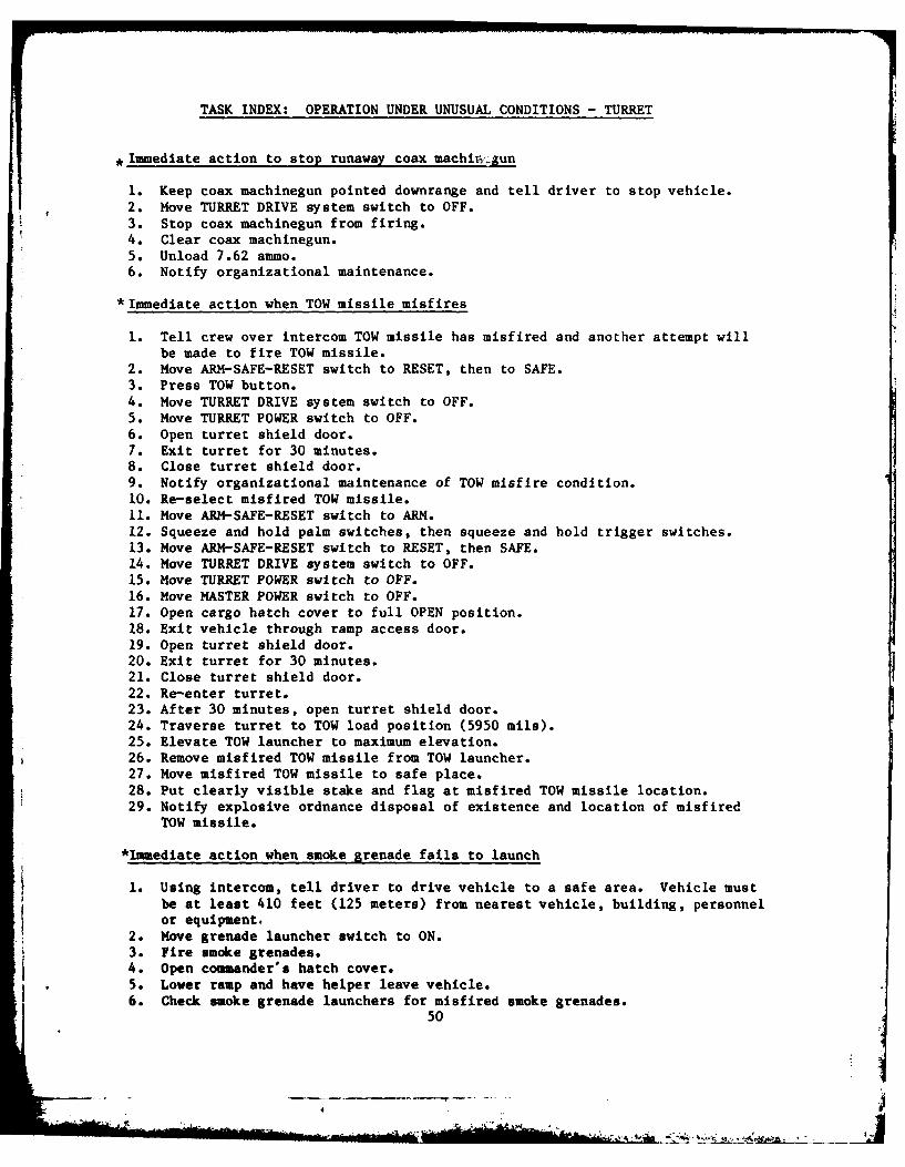
TASK INDEX: OPERATION UNDER UNUSUAL CONDITIONS - TURRET
, Immediate action to stop runaway coax machirzgun
1. Keep coax machinegun pointed downrange and tell driver to stop vehicle.2. Move TURRET DRIVE system switch to OFF.3. Stop coax machinegun from firing.4. Clear coax machinegun.5. Unload 7.62 ammo.6. Notify organizational maintenance.
* Immediate action when TOW missile misfires
1. Tell crew over intercom TOW missile has misfired and another attempt willbe made to fire TOW missile.
2. Move ARM-SAFE-RESET switch to RESET, then to SAFE.3. Press TOW button.4. Move TURRET DRIVE system switch to OFF.5. Move TURRET POWER switch to OFF.6. Open turret shield door.7. Exit turret for 30 minutes.8. Close turret shield door.9. Notify organizational maintenance of TOW misfire condition.10. Re-select misfired TOW missile.11. Move ARM-SAFE-RESET switch to ARM.12. Squeeze and hold palm switches, then squeeze and hold trigger switches.13. Move ARM-SAFE-RESET switch to RESET, then SAFE.14. Move TURRET DRIVE system switch to OFF.15. Move TURRET POWER switch to OFF.16. Move MASTER POWER switch to OFF.17. Open cargo hatch cover to full OPEN position.18. Exit vehicle through ramp access door.19. Open turret shield door.20. Exit turret for 30 minutes.21. Close turret shield door.22. Re-enter turret.23. After 30 minutes, open turret shield door.24. Traverse turret to TOW load position (5950 mils).25. Elevate TOW launcher to maximum elevation.26. Remove misfired TOW missile from TOW launcher.27. Move misfired TOW missile to safe place.28. Put clearly visible stake and flag at misfired TOW missile location.29. Notify explosive ordnance disposal of existence and location of misfired
TOW missile.
*Immediate action when smoke grenade fails to launch
1. Using intercom, tell driver to drive vehicle to a safe area. Vehicle mustbe at least 410 feet (125 meters) from nearest vehicle, building, personnelor equipment,
2. Move grenade launcher switch to ON.3. Fire smoke grenades.4. Open commander's hatch cover.5. Lower ramp and have helper leave vehicle.6. Check smoke grenade launchers for misfired smoke grenades.
50
- 4 - --o
.... , : . : " ..o, u ,, , ". ' -.

TASK INDEX: OPERATION UNDER UNUSUAL CONDITIONS - TURRET
7. Move TURRET POWER switch to OFF.8. Move MASTER POWER switch to OFF.9. Remove misfired smoke grenades from right side smoke grenade launcher.10. Remove misfired smoke grenades from left side smoke grenade launcher.11. Tell gunner that smoke grenade launchers are clear of misfired smoke
grenades and that helper is clear of turret.12. Move smoke grenades to a well-marked spot at least 650 feet (200 meters)
from nearest vehicle, building, personnel, or equipment.13. Notify ordnance disposal of exact location, type, and number of smoke
grenades left at safe location.14. Notify organizational maintenance that smoke grenade launchers on the
vehicle have malfunctioned.
*Immediate action to override hatch switches
1. Remove HATCH INTERLOCK OVERRIDE switch guard.2. Turn on HATCH INTERLOCK OVERRIDE switch.3. Report faulty HATCH INTERLOCK OVERRIDE switch to organizational maintenance.4. When faulty HATCH INTERLOCK OVERRIDE switch is repaired, move it to OFF.5. Install HATCH INTERLOCK OVERRIDE switch guard.
Gain access to turned turret in an emergency
*Immediate action to stop runaway engine
1. Move gear selector to NEUTRAL.2. Turn off fuel control.3. Stop vehicle.4. Set hand brake.5. Traverse turret to 4100 mils.6. Turn off main fuel manual shut-off valve.7. Traverse turret to 6400 mils.8. Notify organizational maintenance.
51
1 Asi