marley twin-wall & twin-wall 700 - hdpe pipe solutions€¦ · marley twin-wall & twin-wall...
TRANSCRIPT
NEW
MarleyTwin-Wall &Twin-Wall 700
uPVC Structured Wall Pipe for underground sewer and drain systems.
Marley Pipe Systems is one of South Africa’s leading manufacturers and suppliers of Plastic Pipe reticulation systems, meeting the needs of the plumbing, civil, agricultural, industrial and petrochemical industries, primarily in South Africa, but also supplying into Africa, the Indian Ocean Islands, Europe, Australia and America.
ContentsIntroduction� 4
Specifications� 4
What is Pipe Stiffness?� 4
SAPPMA� 4
Sizes and Dimensions� 5
Identification and Marking� 5
Fittings� 5
Compatibility� 5
Joints� 5
Features and Benefits� 5
Cleaning� 6
Rodding� 6
Water Jetting� 6
Chemical Resistance� 6
Pipe Flow Characteristics� 6
Trench Load Considerations� 6
Soil and Traffic Loads� 6
Graph 1, Vertical Deflection % on 160mm pipe at depth of cover 0.9m to 10m� 7
Graph 2, Deflection vs soil load on 160mm pipe� 7
Installation� 8
Air Testing procedure� 8
Pipe Cutting� 8
How to Join Socketed Twin-Wall Pipe� 9
How to Join Twin-Wall Pipe using the Push-fit Double Socket� 10
How to Join Twin-Wall Pipe to Marley Fittings� 11
Marley Push-fit Repair Coupling� 12
Pipe Bedding & Backfill� 14
Disclaimer� 15
Document version_002
4
What is Pipe Stiffness?This is the measure of the ability of the pipe to withstand external loads without significant deflection. The higher the pipe stiffness (measured in kPa) the greater the vertical load required to deform the pipe from a normal circular cross-section.
It is important to note that a properly installed pipe forms a “pipe / soil system” and has a vastly increased resistance to deflection than any pipe on its own. A stiffer pipe should therefore not provide an excuse for poor installation practises.
Pipe stiffness and internal pressure are both measured in kPa but must not be confused. Sewer pipes must not be tested to a pressure of 400 kPa or similar. Please refer to “Air testing procedure” for the leak testing of sewer pipes.
SAPPMAMarley Pipe Systems are founder members of the Southern African Plastic Pipe Manufacturers Association (SAPPMA) and as such are subject to peer review of their quality systems and the quality of their products amongst other things. This gives customers further security when specifying or using the products of Marley Pipe Systems.
IntroductionTogether with their international owners, Marley Pipe Systems as worldwide leaders in the development of PVC piping systems are pleased to announce Twin-Wall 700 which offers unprecedented pipe stiffness at competitive prices. Our Twin-Wall has for many years fulfilled a need in the market and Contractors, Municipalities, and Developers will now all benefit from the improved structural performance of Twin-Wall 700. Both products continue to provide the highest levels of hydraulic performance and quality at a highly competitive installed cost.
A “structured wall” or “Twin-Wall” sewer pipe has a corrugated hollow outer wall (providing stiffness) and a smooth inner wall.
An important contribution from Marley Pipe Systems in South Africa’s progress towards providing homes and sanitation for all it’s people.
SpecificationsMarley’s “Twin-Wall” and “Twin-Wall 700” sewer pipe can be specified and used with confidence because it is manufactured by an internationally renowned company, in an ISO 9002 accredited factory to the requirements of SANS 1601 Type 2.
SANS 1601 Type 2 specifies a minimum pipe stiffness of 400 kPa. Marley’s Twin-Wall carries the SABS mark of approval for this specification. Twin-Wall 700 has however been developed with thicker walls than the minimums specified in SANS 1601. This has resulted in a sewer pipe with a pipe stiffness of at least 700 kPa. This represents an increase of a massive 75%.
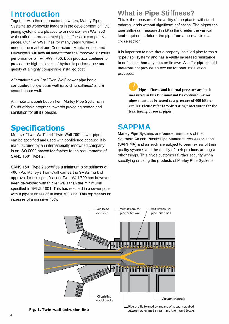
Melt stream for pipe inner wall
Melt stream for pipe outer wall
Circulating mould blocks Vacuum channels
Twin head extruder
Pipe profile formed by means of vacuum applied between outer melt stream and the mould blocksFig. 1, Twin-wall extrusion line
5
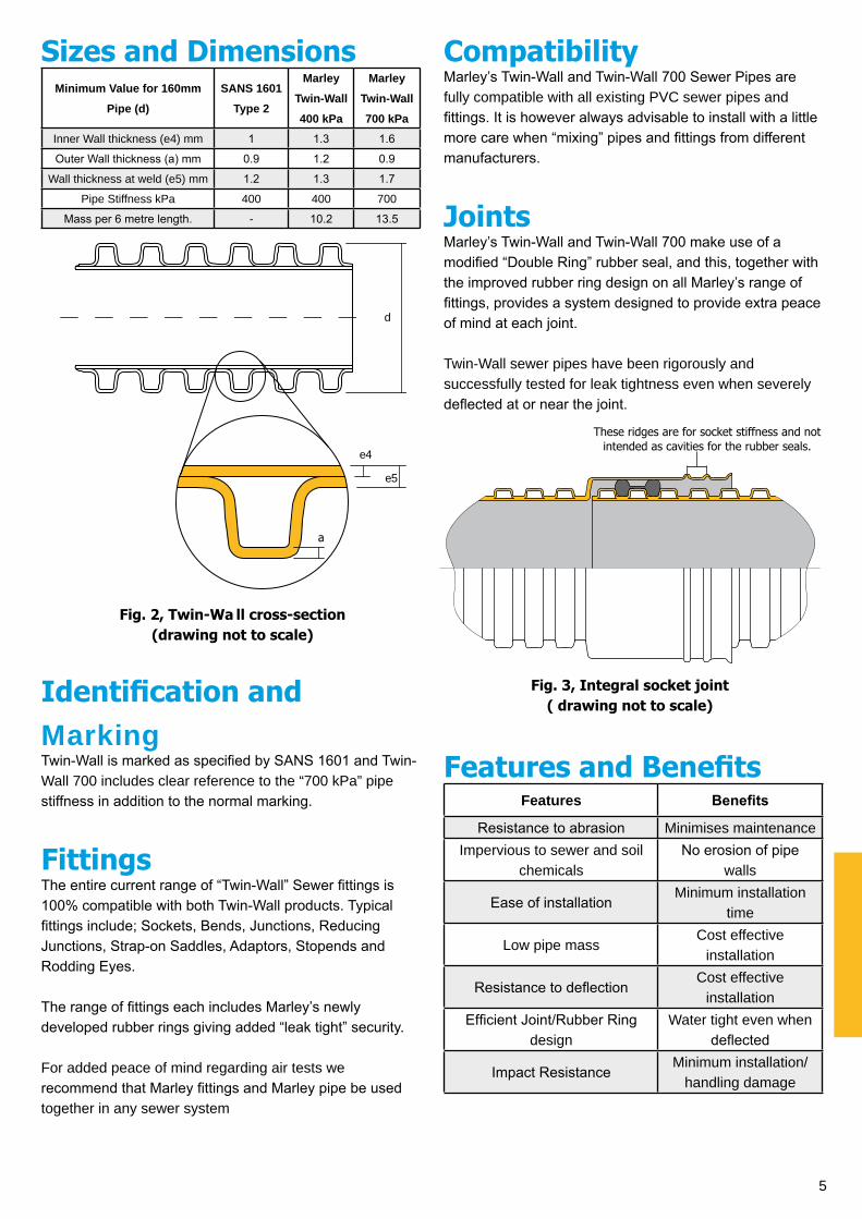
Sizes and DimensionsMinimum Value for 160mm
Pipe (d)
SANS 1601
Type 2
Marley
Twin-Wall
400 kPa
Marley
Twin-Wall
700 kPaInner Wall thickness (e4) mm 1 1.3 1.6
Outer Wall thickness (a) mm 0.9 1.2 0.9
Wall thickness at weld (e5) mm 1.2 1.3 1.7
Pipe Stiffness kPa 400 400 700
Mass per 6 metre length. - 10.2 13.5
Identification and MarkingTwin-Wall is marked as specified by SANS 1601 and Twin-Wall 700 includes clear reference to the “700 kPa” pipe stiffness in addition to the normal marking.
FittingsThe entire current range of “Twin-Wall” Sewer fittings is 100% compatible with both Twin-Wall products. Typical fittings include; Sockets, Bends, Junctions, Reducing Junctions, Strap-on Saddles, Adaptors, Stopends and Rodding Eyes.
The range of fittings each includes Marley’s newly developed rubber rings giving added “leak tight” security.
For added peace of mind regarding air tests we recommend that Marley fittings and Marley pipe be used together in any sewer system
CompatibilityMarley’s Twin-Wall and Twin-Wall 700 Sewer Pipes are fully compatible with all existing PVC sewer pipes and fittings. It is however always advisable to install with a little more care when “mixing” pipes and fittings from different manufacturers.
JointsMarley’s Twin-Wall and Twin-Wall 700 make use of a modified “Double Ring” rubber seal, and this, together with the improved rubber ring design on all Marley’s range of fittings, provides a system designed to provide extra peace of mind at each joint.
Twin-Wall sewer pipes have been rigorously and successfully tested for leak tightness even when severely deflected at or near the joint.
Features and BenefitsFeatures Benefits
Resistance to abrasion Minimises maintenanceImpervious to sewer and soil
chemicalsNo erosion of pipe
walls
Ease of installationMinimum installation
time
Low pipe massCost effective
installation
Resistance to deflectionCost effective
installationEfficient Joint/Rubber Ring
designWater tight even when
deflected
Impact ResistanceMinimum installation/
handling damage
Fig. 2, Twin-Wa ll cross-section (drawing not to scale)
Fig. 3, Integral socket joint( drawing not to scale)
These ridges are for socket stiffness and not intended as cavities for the rubber seals.
e4
a
e5
d
6
CleaningIf a sewer system is correctly designed and laid it is seldom necessary to use rodding or water jetting as a means of cleaning.
RoddingThe efficiency and effectiveness of rodding is dependant largely on the procedures adopted and the correct choice of properly maintained rodding tools. Poor practices and/or damaged or inappropriate rodding tools could lead to damage to any type of sewer pipes. It is advisable to consult a drain cleaning expert to ensure that the correct methods and equipment are used.
Water JettingWater jetting is now frequently used as a means for cleaning and maintaining sewers and drains.
The Water Research Council of the United Kingdom has published a “Sewer Jetting Code of Practice”. This code and their pipe material selection criteria were used as a basis of water jetting tests carried by Marley Pipe Systems, under the auspices of the Structured Wall Pipe Association of South Africa. Marley’s Solid wall and Twin-Wall sewer pipes were found to meet the particularly stringent test criteria of this Code of Practice.
Marley’s Twin-Wall Sewer pipes have also been approved for use by the E’Tekwini Metro Council after having passed regular water jetting tests by that Council. The criteria for this test are as follows: 180 Bar for 120 seconds using a nozzle diameter of 1.5mm from a distance of 5mm.
When water jetting equipment is operated in accordance with the manufacturers operating instructions then accidental damage to the sewer system and injury to the operators will be avoided.
Chemical ResistanceMarley Pipe Systems have published separately, “Chemical Resistance Data”, as a guide to the behaviour of Thermoplastic and Elastomeric materials when exposed a range of chemical products
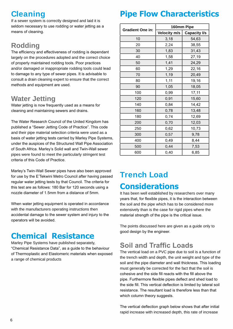
Pipe Flow Characteristics
Gradient One in:160mm Pipe
Velocity m/s Capacity I/s10 3,18 54,6320 2,24 38,5530 1,83 31,4340 1,58 27,1950 1,41 24,2960 1,29 22,1670 1,19 20,4980 1,11 19,1690 1,05 18,05100 0,99 17,11120 0,91 15,60140 0,84 14,42160 0,78 13,48180 0,74 12,69200 0,70 12,03250 0,62 10,73300 0,57 9,78400 0,49 8,44500 0,44 7,53600 0,40 6,85
Trench Load ConsiderationsIt has been well established by researchers over many years that, for flexible pipes, it is the interaction between the soil and the pipe which has to be considered more extensively than is the case for rigid pipes where the material strength of the pipe is the critical issue.
The points discussed here are given as a guide only to good design by the engineer.
Soil and Traffic LoadsThe vertical load on a PVC pipe due to soil is a function of the trench width and depth, the unit weight and type of the soil and the pipe diameter and wall thickness. This loading must generally be corrected for the fact that the soil is cohesive and the side fill reacts with the fill above the pipe. Furthermore flexible pipes deflect and shed load to the side fill. This vertical deflection is limited by lateral soil resistance. The resultant load is therefore less than that which column theory suggests.
The vertical deflection graph below shows that after initial rapid increase with increased depth, this rate of increase
7
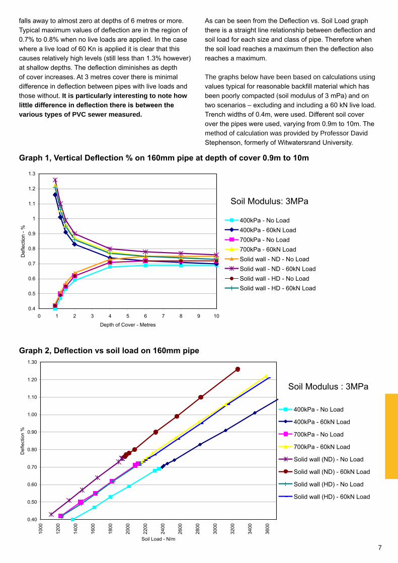
falls away to almost zero at depths of 6 metres or more. Typical maximum values of deflection are in the region of 0.7% to 0.8% when no live loads are applied. In the case where a live load of 60 Kn is applied it is clear that this causes relatively high levels (still less than 1.3% however) at shallow depths. The deflection diminishes as depth of cover increases. At 3 metres cover there is minimal difference in deflection between pipes with live loads and those without. It is particularly interesting to note how little difference in deflection there is between the various types of PVC sewer measured.
As can be seen from the Deflection vs. Soil Load graph there is a straight line relationship between deflection and soil load for each size and class of pipe. Therefore when the soil load reaches a maximum then the deflection also reaches a maximum.
The graphs below have been based on calculations using values typical for reasonable backfill material which has been poorly compacted (soil modulus of 3 mPa) and on two scenarios – excluding and including a 60 kN live load. Trench widths of 0.4m, were used. Different soil cover over the pipes were used, varying from 0.9m to 10m. The method of calculation was provided by Professor David Stephenson, formerly of Witwatersrand University.
Graph 1, Vertical Deflection % on 160mm pipe at depth of cover 0.9m to 10m
Graph 2, Deflection vs soil load on 160mm pipe
8
InstallationAll work should be in accordance with national building regulations and applicable bylaws. Information in this section is intended to highlight and supplement relevant sections of South African National Standards; SANS 10400, SANS 10112, SANS 10252-2 and SANS 1200LD.
For secure joints, only use pipe and fittings from the Marley Sewer & Drainage range. When joining, sockets and seals must be clean and free from swarf or any grit.
SANS 10252-2, section 6.8 details the correct test and inspection procedure to follow before any work is concealed or covered. Local authorities may require tests for drains to be carried out as detailed in SANS 10400 Part P, item PP26.
Air Testing procedureTo ensure that a newly laid sewer line does not leak contaminated water into the surrounding soil it is necessary to carry out an air test (manometer test) as is recommended in SANS 10252-2.
Pipe stiffness and internal pressure are both
measured in kPa but must not be confused. Sewer pipes must not be tested to a pressure of 400 kPa or similar. Please refer to “Air testing procedure” for the leak testing of sewer pipes.
The equipment needed for air testing procedure:A manometer with an air pump and connecting hoses.Test plugs and end caps.Soapy water (or smoke producing equipment).
ProcedureFill all traps (in the section to be tested) with water.Fit test plugs to all open ended pipes and fittings in the section to be tested.Ensure that all access covers are securely in place.Fit the manometer to one of the test plugs and ensure that the water level is adjusted to zero.Pump air into the system until the manometer gives a pressure reading of about 350mm of water.Close the valve on the manometer and allow the water level to stabilise for a couple of minutes.Make sure there are no leaks in the test equipment.Adjust the pressure down to 250mm of water.Start recording the time. The pressure is allowed to drop to no less than 125mm of water within a minimum period of time which varies according to the size of the line being tested
•••
••
••
•
•
•••
Pipe size mm Minimum time minutes
110 2160 3200 4250 4.5
Table of minimum times for pressure drop to no less than 125mm of water.
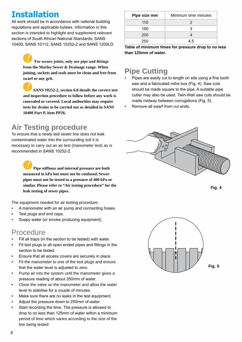
Pipe CuttingPipes are easily cut to length on site using a fine tooth saw and a fabricated mitre box (Fig. 4). Saw cuts should be made square to the pipe. A suitable pipe cutter may also be used. Twin-Wall saw cuts should be made midway between corrugations (Fig. 5).Remove all swarf from cut ends.
•
•
Fig. 4
Fig. 5
9
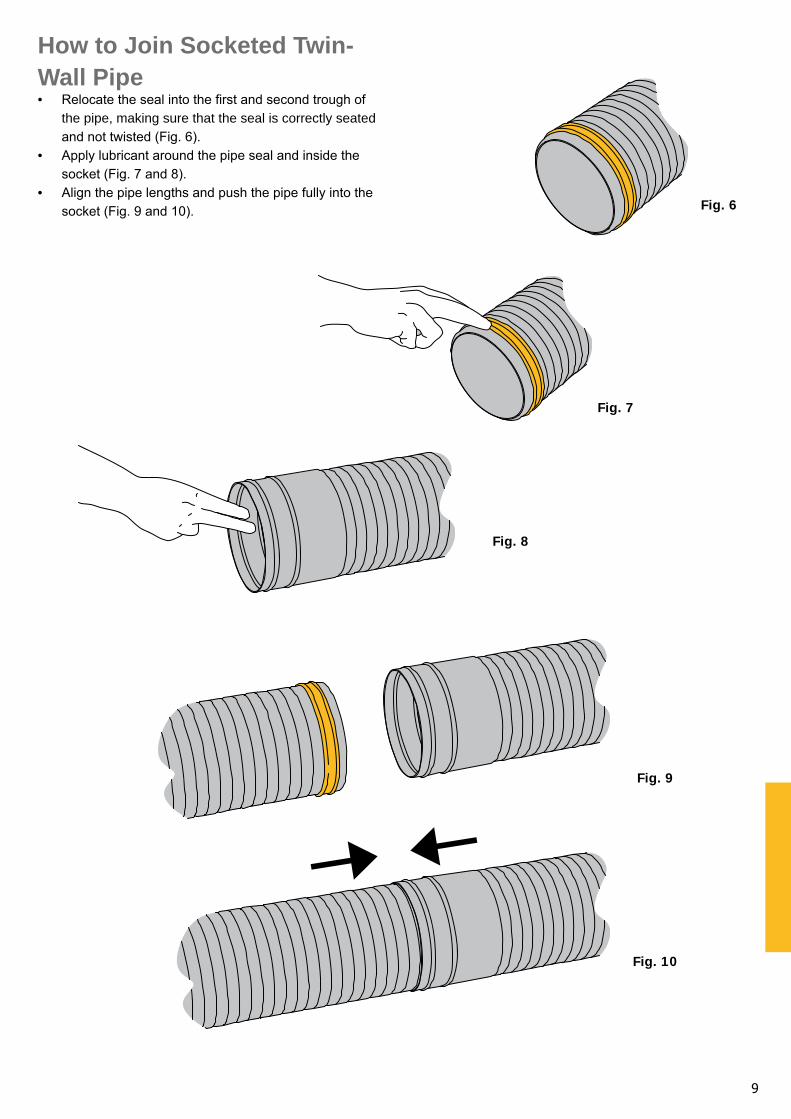
How to Join Socketed Twin-Wall Pipe
Relocate the seal into the first and second trough of the pipe, making sure that the seal is correctly seated and not twisted (Fig. 6).Apply lubricant around the pipe seal and inside the socket (Fig. 7 and 8).Align the pipe lengths and push the pipe fully into the socket (Fig. 9 and 10).
•
•
•Fig. 6
Fig. 7
Fig. 8
Fig. 9
Fig. 10
10
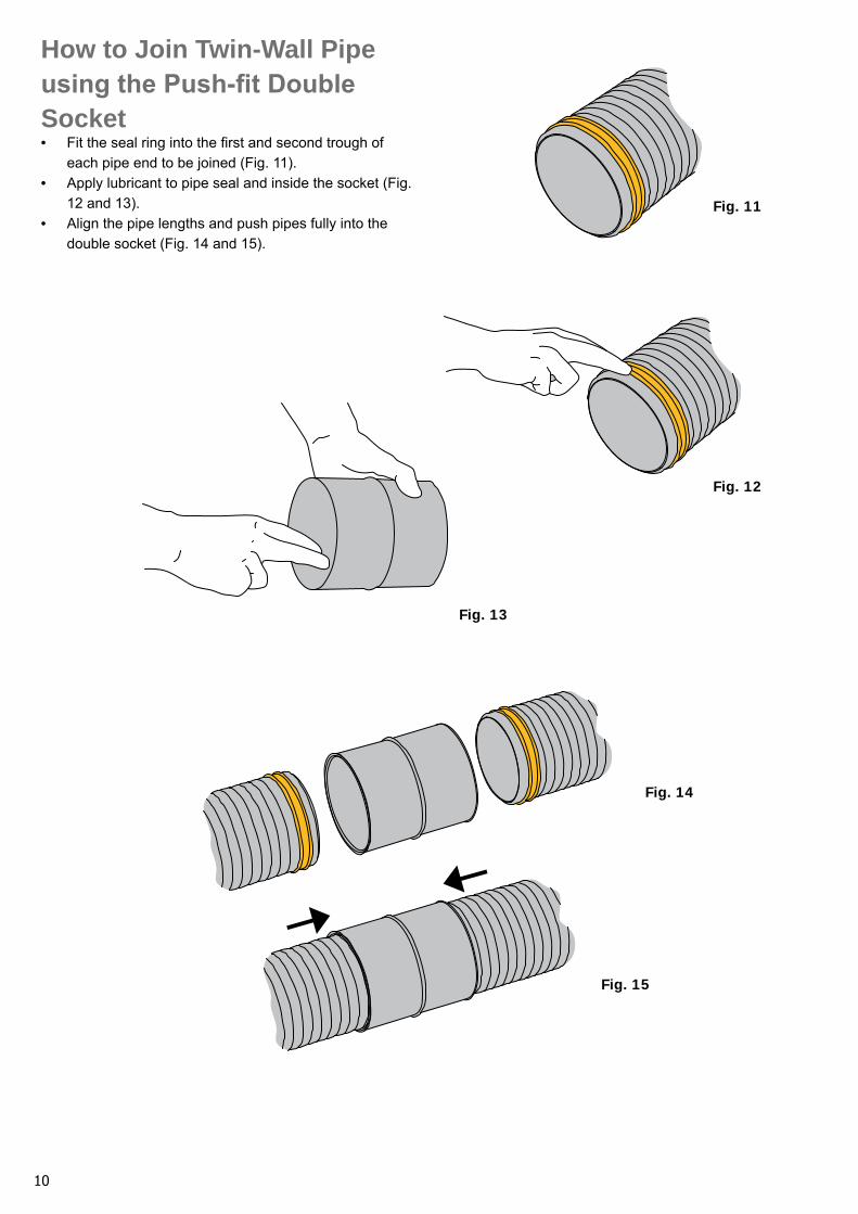
How to Join Twin-Wall Pipe using the Push-fit Double Socket
Fit the seal ring into the first and second trough of each pipe end to be joined (Fig. 11).Apply lubricant to pipe seal and inside the socket (Fig. 12 and 13).Align the pipe lengths and push pipes fully into the double socket (Fig. 14 and 15).
•
•
•Fig. 11
Fig. 12
Fig. 13
Fig. 14
Fig. 15
11
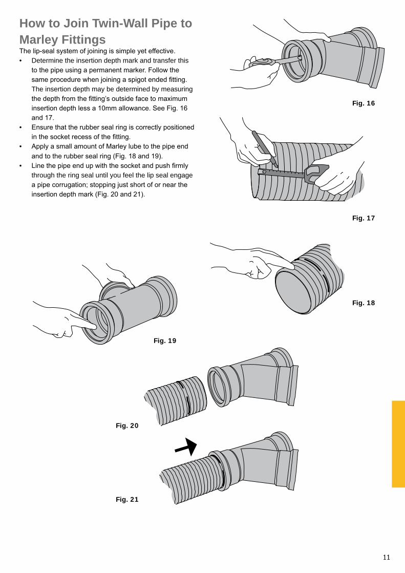
How to Join Twin-Wall Pipe to Marley FittingsThe lip-seal system of joining is simple yet effective.
Determine the insertion depth mark and transfer this to the pipe using a permanent marker. Follow the same procedure when joining a spigot ended fitting. The insertion depth may be determined by measuring the depth from the fitting’s outside face to maximum insertion depth less a 10mm allowance. See Fig. 16 and 17.Ensure that the rubber seal ring is correctly positioned in the socket recess of the fitting.Apply a small amount of Marley lube to the pipe end and to the rubber seal ring (Fig. 18 and 19).Line the pipe end up with the socket and push firmly through the ring seal until you feel the lip seal engage a pipe corrugation; stopping just short of or near the insertion depth mark (Fig. 20 and 21).
•
•
•
•
Fig. 16
Fig. 17
Fig. 18
Fig. 19
Fig. 20
Fig. 21
12
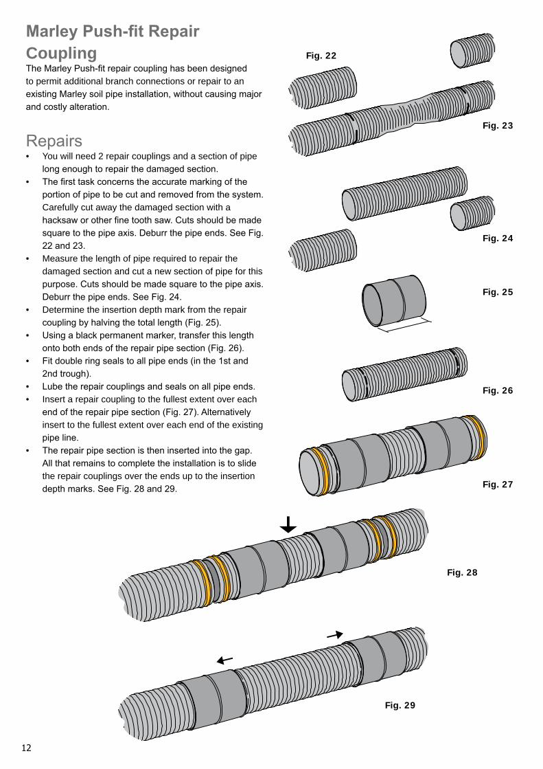
Marley Push-fit Repair CouplingThe Marley Push-fit repair coupling has been designed to permit additional branch connections or repair to an existing Marley soil pipe installation, without causing major and costly alteration.
RepairsYou will need 2 repair couplings and a section of pipe long enough to repair the damaged section.The first task concerns the accurate marking of the portion of pipe to be cut and removed from the system. Carefully cut away the damaged section with a hacksaw or other fine tooth saw. Cuts should be made square to the pipe axis. Deburr the pipe ends. See Fig. 22 and 23.Measure the length of pipe required to repair the damaged section and cut a new section of pipe for this purpose. Cuts should be made square to the pipe axis. Deburr the pipe ends. See Fig. 24.Determine the insertion depth mark from the repair coupling by halving the total length (Fig. 25).Using a black permanent marker, transfer this length onto both ends of the repair pipe section (Fig. 26).Fit double ring seals to all pipe ends (in the 1st and 2nd trough).Lube the repair couplings and seals on all pipe ends.Insert a repair coupling to the fullest extent over each end of the repair pipe section (Fig. 27). Alternatively insert to the fullest extent over each end of the existing pipe line.The repair pipe section is then inserted into the gap. All that remains to complete the installation is to slide the repair couplings over the ends up to the insertion depth marks. See Fig. 28 and 29.
•
•
•
•
•
•
••
•
Fig. 24
Fig. 25
Fig. 26
Fig. 27
Fig. 28
Fig. 29
Fig. 22
Fig. 23
13
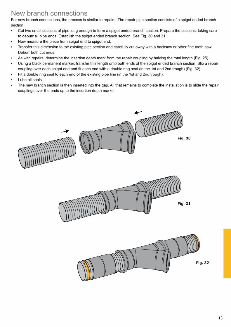
New branch connectionsFor new branch connections, the process is similar to repairs. The repair pipe section consists of a spigot ended branch section.
Cut two small sections of pipe long enough to form a spigot ended branch section. Prepare the sections, taking care to deburr all pipe ends. Establish the spigot ended branch section. See Fig. 30 and 31.Now measure the piece from spigot end to spigot end.Transfer this dimension to the existing pipe section and carefully cut away with a hacksaw or other fine tooth saw. Deburr both cut ends.As with repairs, determine the insertion depth mark from the repair coupling by halving the total length (Fig. 25).Using a black permanent marker, transfer this length onto both ends of the spigot ended branch section. Slip a repair coupling over each spigot end and fit each end with a double ring seal (in the 1st and 2nd trough) (Fig. 32).Fit a double ring seal to each end of the existing pipe line (in the 1st and 2nd trough).Lube all seals.The new branch section is then inserted into the gap. All that remains to complete the installation is to slide the repair couplings over the ends up to the insertion depth marks.
•
••
••
•••
Fig. 30
Fig. 31
Fig. 32
14
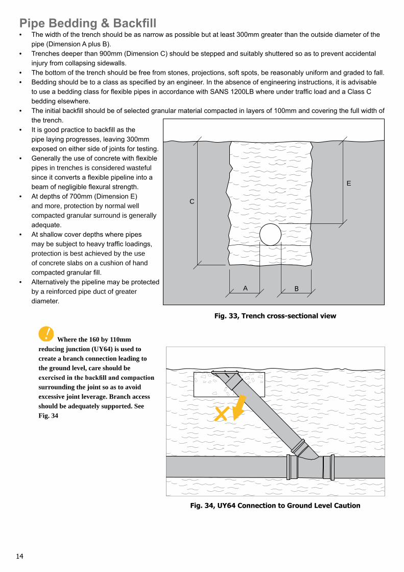
Pipe Bedding & BackfillThe width of the trench should be as narrow as possible but at least 300mm greater than the outside diameter of the pipe (Dimension A plus B).Trenches deeper than 900mm (Dimension C) should be stepped and suitably shuttered so as to prevent accidental injury from collapsing sidewalls.The bottom of the trench should be free from stones, projections, soft spots, be reasonably uniform and graded to fall.Bedding should be to a class as specified by an engineer. In the absence of engineering instructions, it is advisable to use a bedding class for flexible pipes in accordance with SANS 1200LB where under traffic load and a Class C bedding elsewhere.The initial backfill should be of selected granular material compacted in layers of 100mm and covering the full width of the trench.It is good practice to backfill as the pipe laying progresses, leaving 300mm exposed on either side of joints for testing.Generally the use of concrete with flexible pipes in trenches is considered wasteful since it converts a flexible pipeline into a beam of negligible flexural strength.At depths of 700mm (Dimension E) and more, protection by normal well compacted granular surround is generally adequate.At shallow cover depths where pipes may be subject to heavy traffic loadings, protection is best achieved by the use of concrete slabs on a cushion of hand compacted granular fill.Alternatively the pipeline may be protected by a reinforced pipe duct of greater diameter.
Where the 160 by 110mm reducing junction (UY64) is used to create a branch connection leading to the ground level, care should be exercised in the backfill and compaction surrounding the joint so as to avoid excessive joint leverage. Branch access should be adequately supported. See Fig. 34
•
•
••
•
•
•
•
•
•A
E
C
B
Fig. 33, Trench cross-sectional view
Fig. 34, UY64 Connection to Ground Level Caution

DisclaimerWhilst every care has been taken in the preparation of this instruction manual, neither Marley Pipe Systems nor any of their agencies can be held liable for any errors in this publication. It should also be noted that this manual is intended for reference only. Due consultation is required when designing for particular applications, and no liability will be entertained in this regard.
NOTES

Marley-twin-wall-pipe_v002
BranchesJohannesburg | Bloemfontein | Durban | East London | George | Nelspruit
Polokwane | Port Elizabeth | Marley Export DivisionHead Office: 1 Bickley Road, Pretoriusstad, Nigel • P.O. Box 67, Nigel, 1490
www.marleypipesystems.co.za
Tel: 0861-MARLEY(0861-627539)