marlene h. dortch, secretary 445 12th street, sw docs/oct 29, 2004...i october 29, 2004 marlene h....
TRANSCRIPT
i
October 29, 2004 Marlene H. Dortch, Secretary Federal Communications Commission Office of the Secretary 445 12th Street, SW Washington, DC 20554 Re: CC Docket No. 94-102 Dear Ms. Dortch: The Emergency Services Interconnection Forum (“ESIF”) hereby submits the attached document for inclusion in the record in CC Docket 94-102. In its Third Report and Order, the Commission established accuracy requirements for network and handset based location solutions for Enhanced 9-1-1 emergency call services.1 As a result, the ESIF identified the need for industry-accepted requirements for testing the accuracy performance of Wireless E-9-1-1 Phase II systems, and developed ESIF Technical Report - ATIS-050001: High Level Requirements for Accuracy Testing Methodologies (7/23/04). This document provides a common frame of reference that individual stakeholders may use to validate the accuracy methodology of 9-1-1 location technologies. If you have any questions or concerns, please direct them to me at (202) 434-8830 or via email at [email protected]. Sincerely,
Toni Haddix Staff Attorney Attachment: ESIF Technical Report – ATIS 0500001 High Level Requirements for Accuracy Testing Methodologies 1 In the Matter of Revision of the Commissions Rules to Ensure Compatablity with Enhanced 911 Emergency Calling Systems, CC Docket 94-102, Third Report and Order, (September 15, 1999).
ESIF TECHNICAL REPORT
ATIS-0500001
High Level Requirements for
Accuracy Testing Methodologies
ATIS-0500001
ii
ATIS is a technical planning and standards development organization that is committed to rapidly developing and promoting technical and operations standards for the communications and related information technologies industry worldwide using a pragmatic, flexible and open approach. Over 1,100 participants from more than 350 communications companies are active in ATIS’ 22 industry committees, and its Incubator Solutions Program. www.atis.org
REVISION HISTORY ATIS-0500001 High Level Requirements for Accuracy Testing Methodologies
Version Date Changes
1.0 05-11-2004 Initial Release
1.1 07-23-2004 Final Release
ATIS-0500001: High Level Requirements for Accuracy Testing Methodologies is an ATIS standard developed by the following committee(s) under the ATIS User Interface functional group: The Emergency Services Interconnection Forum (ESIF), Subcommittee G
Published by The Alliance for Telecommunications Industry Solutions (ATIS) 1200 G Street, NW, Suite 500 Washington, DC 20005 Copyright © 2004 by Alliance for Telecommunications Industry Solutions All rights reserved. No part of this publication may be reproduced in any form, in an electronic retrieval system or otherwise, without the prior written permission of the publisher. For information contact ATIS at (202) 628-6380. ATIS is online at: http://www.atis.org. Printed in the United States of America.

ATIS-0500001
iii
Disclaimer and Limitation of Liability
The information provided in this document is directed solely to professionals who have the appropriate degree of experience to understand and interpret its contents in accordance with generally accepted engineering or other professional standards and applicable regulations. No recommendation as to products or vendors is made or should be implied. NO REPRESENTATION OR WARRANTY IS MADE THAT THE INFORMATION IS TECHNICALLY ACCURATE OR SUFFICIENT OR CONFORMS TO ANY STATUTE, GOVERNMENTAL RULE OR REGULATION, AND FURTHER NO REPRESENTATION OR WARRANTY IS MADE OF MERCHANTABILITY OR FITNESS FOR ANY PARTICULAR PURPOSE OR AGAINST INFRINGEMENT OF INTELLECTUAL PROPERTY RIGHTS. ATIS SHALL NOT BE L IABLE, BEYOND THE AMOUNT OF ANY SUM RECEIVED IN PAYMENT BY ATIS FOR THIS DOCUMENT, WITH RESPECT TO ANY CLAIM, AND IN NO EVENT SHALL ATIS BE LIABLE FOR LOST PROFITS OR OTHER INCIDENTAL OR CONSEQUENTIAL DAMAGES. ATIS EXPRESSLY ADVISES THAT ANY AND ALL USE OF OR RELIANCE UPON THE INFORMATION PROVIDED IN THIS DOCUMENT IS AT THE RISK OF THE USER.
ATIS-0500001
iv
TABLE OF CONTENTS
1 Introduction .............................................................................................................1
2 Definitions ................................................................................................................1 2.1 Acronyms......................................................................................................................................................2
3 General Test Requirements.................................................................................3 3.1 Introduction..................................................................................................................................................3 3.2 Basic Testing Requirements .....................................................................................................................3 3.3 General Testing Framework......................................................................................................................3 3.4 System Diagram for Location Network Testing......................................................................................4
4 Equipment Requirements ....................................................................................6 4.1 Test Phones .................................................................................................................................................6 4.2 Equipment to Establish Ground Truth .....................................................................................................6 4.3 Data Recording Device..............................................................................................................................6
5 Software Requirements........................................................................................7
6 Test Area ..................................................................................................................7 6.1 Definition of Test Area................................................................................................................................7
7 Empirical Test Methods........................................................................................7 7.1 General.........................................................................................................................................................7 7.2 Test Locations .............................................................................................................................................7 7.3 Static/Dynamic Testing..............................................................................................................................8 7.4 Indoor/Outdoor Testing ..............................................................................................................................9 7.5 Handset Test Equipment...........................................................................................................................9 7.6 Test Conduct................................................................................................................................................9
8 Predictive Test Methods.....................................................................................10 8.1 Objective.....................................................................................................................................................10 8.2 Attributes of Suitable Modeling Tools....................................................................................................10 8.3 Relationship between Predictive Modeling and Empirical Methods .................................................11 8.4 Consistency of Predictive and Empirical Results.................................................................................11 8.5 Requirements for Using Predictive Modeling in E911 Accuracy Determination.............................11
9 Analysis and Summary of Results ..................................................................12 9.1 Objective.....................................................................................................................................................12 9.2 Data Format...............................................................................................................................................12 9.3 Data Analysis Tools and Software.........................................................................................................12 9.4 Processing of Test Call Data...................................................................................................................13 9.5 Data Summaries and Reports.................................................................................................................14
ANNEX A: On Confidence Intervals and Levels for Location Testing..........16
ANNEX B: Example of using the 90% confidence interval to obtain a statistically significant sample size........................................................................17
ATIS-0500001
v
LIST OF FIGURES
Figure 3-1: Accuracy Testing Methodology Framework ...........................................4
Figure 3-2: System under Test Boundary for Location Accuracy (ANSI-41 Networks)...................................................................................................................5
Figure 3-3: System under Test Boundary for Location Accuracy (GSM MAP Networks)...................................................................................................................5
ATIS-0500001
1
1 INTRODUCTION 1
The United States Federal Communications Commission has established accuracy 2
requirements for network and handset based location solutions for Enhanced 9-1-1 3
emergency call services. These requirements can be found in the Commission’s Third 4
Report and Order, adopted September 15, 1999. 5
The Emergency Services Interconnection Forum (ESIF) identified the need for industry 6
accepted requirements for testing the accuracy performance of Wireless E-911 Phase II 7
systems. 8
This document neither recommends, nor imposes a specific test methodology, but rather 9
provides a common frame of reference that individual stakeholders can use to validate 10
the accuracy methodology of 911 location technologies. This document provides a set of 11
minimum requirements individual test methodologies should comply to. 12
Every possible effort has been made to ensure that these requirements remain 13
technology neutral. 14
Per current ESIF Operating Guidelines, due process has been followed in the creation of 15
this document, and development has been open for participation within the bounds of 16
ESIF. 17
Scope 18
This document focuses on providing a set of minimum requirements for the “Accuracy 19
Testing” phase of a typical network deployment of positioning technologies for Wireless 20
E-911. Other testing phases are beyond the scope of this document. 21
This document addresses the technical aspects of accuracy testing. Testing and carrier 22
compliance reporting are two distinct and separate issues. The application of this 23
methodology to compliance reporting is beyond the scope of this document. 24
Acknowledgements 25
Study Group G would like to thank individual members for their active participation and 26
contribution to the creation of this document. 27
References 28
[1] Guidelines for Testing and Verifying the Accuracy of Wireless E911 Location 29
Systems (OET Bulletin No. 71) 30
Federal communications Commission, USA 31
April 12, 2000 32
[2] CDG Test Plan Document for Location Determination Technologies Evaluation 33
CDMA Development Group 34
2000 35
[3] Enhanced Wireless 9-1-1 Phase 2 36
J-STD-036-A 37
Telecommunications Industry Association and Alliance for Telecommunications 38
Industry Solutions 39
June 2002 40
2 DEFINITIONS 41
This section offers a few definitions found to be important to maintain a common 42
vocabulary throughout the creation of this document. 43
Accuracy Testing 44
ATIS-0500001
2
Accuracy testing, whether through empirical and/or predictive test methods, consists of 1
generating location data to gauge the accuracy performance of the system. Location 2
data, typically significant in volume, involves the location infrastructure of the carrier’s 3
network. The primary objective is to verify location accuracy and correct any location 4
system errors. Limiting the test to the carrier’s location network minimizes impact to the 5
rest of the Phase II network and maximizes the capability of the carriers to optimize their 6
system. 7
Functionality Testing (End to End) 8
Functionality testing consists of testing the delivery of the location data from the carrier to 9
the PSAP. The objective of this testing activity is to ensure interoperability between the 10
carrier and the Emergency Service Network. This testing activity requires tight 11
coordination among the involved parties, which normally includes the Emergency Service 12
Network, the carrier and the technology vendors. 13
Maintenance Testing 14
Maintenance testing may be conducted after a system has been turned up with the 15
Emergency Service Network. Like all network systems, maintenance testing will be 16
conducted as needed to ensure functionality and performance. This testing activity may 17
include functionality and/or accuracy testing and the participation of the Emergency 18
Service Network may or may not be required. Maintenance testing can be a condensed 19
version of the original accuracy and functionality testing. 20
Empiric Testing 21
An empirical location accuracy test consists of measuring the difference between a 22
location established by typical surveying techniques or by a differential GPS receiver or 23
similar means and the location estimate provided by the wireless carrier. 24
Predictive Testing 25
A predictive test method consists of utilizing a predictive model to compute the expected 26
accuracy of a location determining technology within a wireless carrier's service area. 27
The predictive model takes into account the physical elements of the location determining 28
system for network or handset based solutions as well as the relevant terrain and RF 29
propagation characteristics. 30
2.1 Acronyms 31
AFLT Advanced Forward Link Trilateration AGPS Assisted GPS ALI Automatic Location Identification ANSI American National Standards Institute AOA Angle of Arrival E-911 Enhanced 911 Emergency Service ESME Emergency Services Messaging Entity ESNE Emergency Services Network Entity GMLC Gateway Mobile Location Center GPS Global Positioning System GSM Global System for Mobile Communications MPC Mobile Positioning Center MSC Mobile Switching Center PDE Position Determining Equipment PSAP Public Safety Answering Point RF Radio Frequency S/R Selective Router SMLC Serving Mobile Location Center TDOA Time Difference of Arrival
ATIS-0500001
3
U-TDOA Uplink TDOA WAAS GPS Wide Area Augmentation System GPS
1
3 GENERAL TEST REQUIREMENTS 2
3.1 Introduction 3
This section on General Test Requirements serves the following purposes: 4
1. It lists a set of basic, concise and broad requirements for the methodology addressed 5
in this document to test and validate the accuracy of an E911, Phase II location 6
system as it is implemented in a given wireless service provider’s network. 7
2. It introduces the framework for this methodology, which consists of related, cohesive 8
elements (described in the remaining chapters of this document) that form the basis 9
for the test methodology. 10
3. It defines the context for the “system under test” to which this methodology is applied. 11
For reference, there is a system diagram for the location network being tested that 12
identifies interface points for accuracy testing within ANSI 41 and GSM MAP 13
networks (Figure 3-2and Figure 3-3). 14
3.2 Basic Testing Requirements 15
In general, the following basic requirements will be satisfied as part of the ESIF Accuracy 16
Testing: 17
• Accuracy testing shall be accomplished in a manner that minimizes its impact on 18
the wireless network, including the air interface, the location technology, and all 19
other elements involved in E911 call processing. 20
• Accuracy testing results shall be representative of the location information that 21
will be delivered to the Emergency Services Network. 22
• Accuracy testing shall be performed in a manner minimizing or not interfering 23
with PSAP operations. 24
• Accuracy testing shall be consistent with the spirit and overall objectives of OET 25
Bulletin 71 Guidelines. 26
• Accuracy testing shall aim to satisfy the diverse objectives of the wireless E911 27
stakeholders. 28
• Accuracy testing shall be documented for purposes of review and maintaining an 29
accurate record of test results. 30
• The test objectives shall be clearly defined and understood by all involved 31
parties. A pass or fail criteria shall be clearly stated prior to any test activities. 32
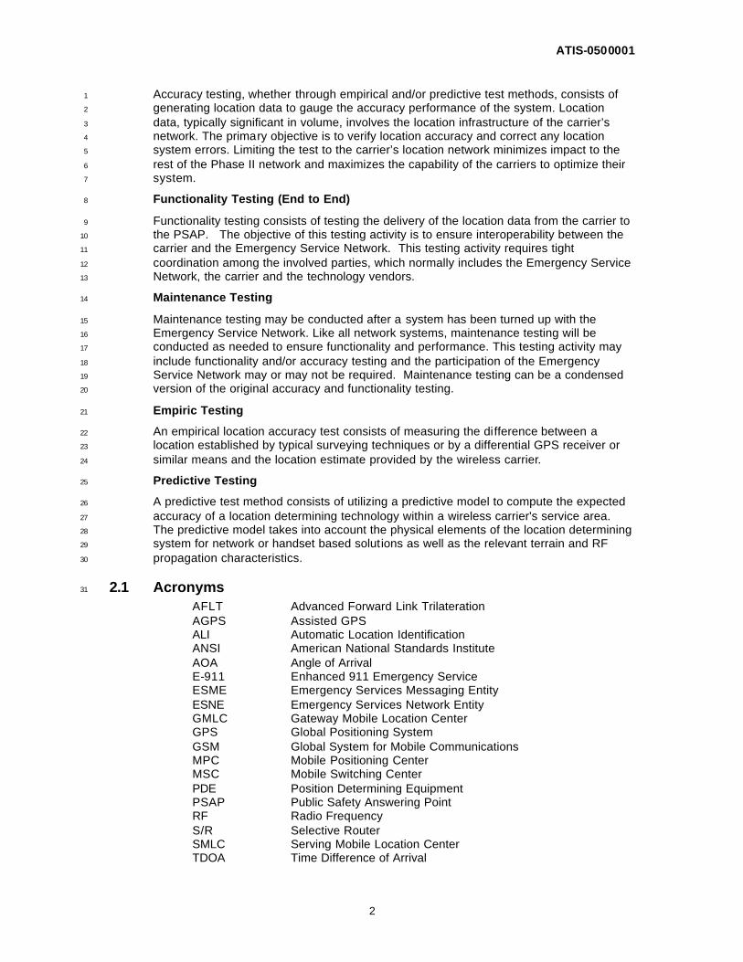
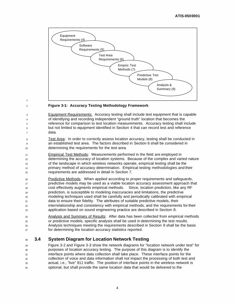
3.3 General Testing Framework 33
The ESIF testing framework identifies all the critical and interrelated elements required to 34
perform accuracy testing of an E911 Phase II location system. Figure 3-1 depicts this 35
framework. It starts with requirements for testing equipment, test area definition and 36
description, actual testing methods (both empirical methods and predictive modeling with 37
empirical verification) and analysis and summary reporting. The sections within this 38
document follow this sequence reflected in Figure 3-1. Each is concisely outlined below. 39
40
ATIS-0500001
4
1
Figure 3-1: Accuracy Testing Methodology Framework 2
Equipment Requirements: Accuracy testing shall include test equipment that is capable 3
of identifying and recording independent “ground truth” location that becomes the 4
reference for comparison to test location measurements. Accuracy testing shall include 5
but not limited to equipment identified in Section 4 that can record test and reference 6
data. 7
Test Area: In order to correctly assess location accuracy, testing shall be conducted in 8
an established test area. The factors described in Section 6 shall be considered in 9
determining the requirements for the test area. 10
Empirical Test Methods: Measurements performed in the field are employed in 11
determining the accuracy of location systems. Because of the complex and varied nature 12
of the landscape in which wireless networks operate, empirical testing shall be the 13
primary method of accuracy determination. Empirical testing methodologies and their 14
requirements are addressed in detail in Section 7. 15
Predictive Methods: When applied according to proper requirements and safeguards, 16
predictive models may be used as a viable location accuracy assessment approach that 17
cost effectively augments empirical methods. Since, location prediction, like any RF 18
prediction, is susceptible to modeling inaccuracies and limitations, the predictive 19
modeling techniques used shall be carefully and periodically calibrated with empirical 20
data to ensure their fidelity. The attributes of suitable predictive models, their 21
interrelationship and consistency with empirical methods, and the requirements for their 22
application based on sound engineering practice are described in Section 8. 23
Analysis and Summary of Results: After data has been collected from empirical methods 24
or predictive models, specific analysis shall be used in determining the test results. 25
Analysis techniques meeting the requirements described in Section 9 shall be the basis 26
for determining the location accuracy statistics reported. 27
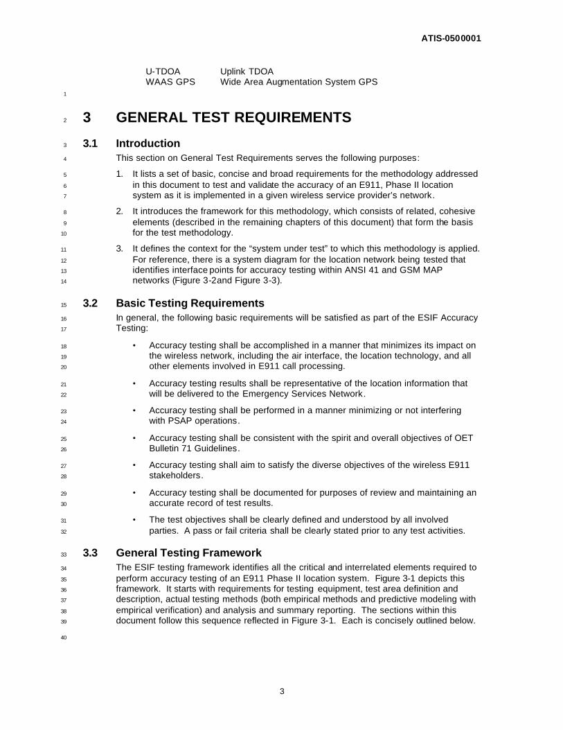
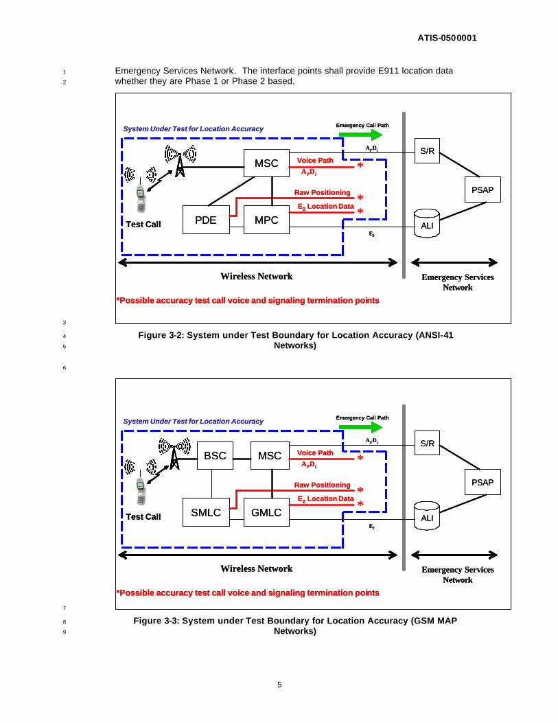
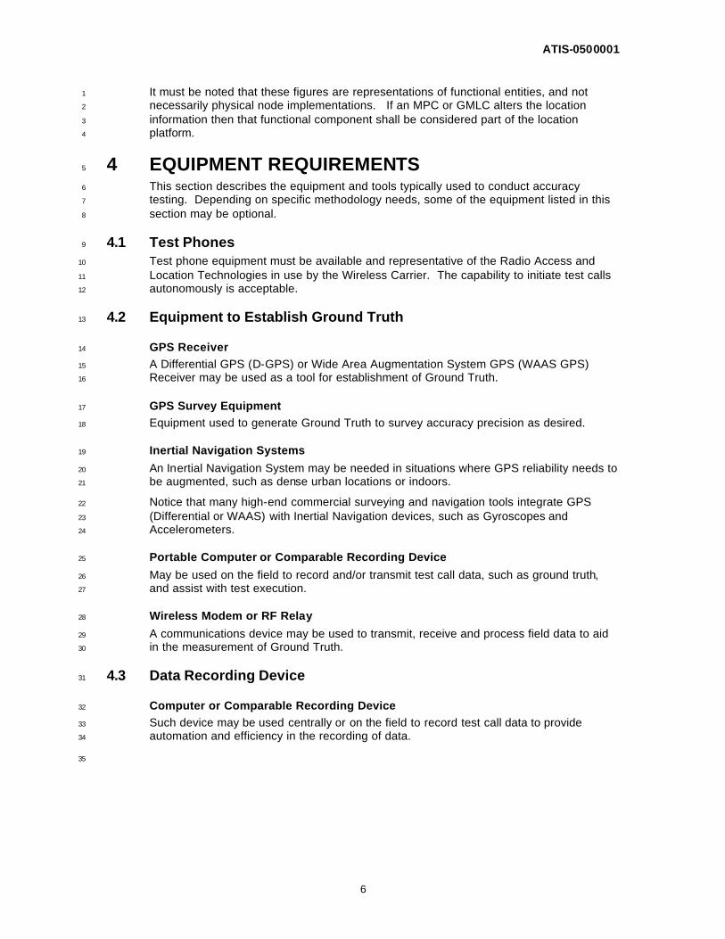
3.4 System Diagram for Location Network Testing 28
Figure 3-2 and Figure 3-3 show the network diagrams for “location network under test” for 29
purposes of location accuracy testing. The purpose of this diagram is to identify the 30
interface points where data collection shall take place. These interface points for the 31
collection of voice and data information shall not impact the processing of both test and 32
actual, i.e., “live” 911 traffic. The position of interface points in the wireless network is 33
optional, but shall provide the same location data that would be delivered to the 34
Equipment Requirements (4)
Software Requirements (5)
Test Area Requirements (6)
Empiric Test Methods (7)
Predictive Test Models (8)
Analysis & Summary (9)
ATIS-0500001
5
Emergency Services Network. The interface points shall provide E911 location data 1
whether they are Phase 1 or Phase 2 based. 2
3
Figure 3-2: System under Test Boundary for Location Accuracy (ANSI-41 4
Networks) 5
6
7
Figure 3-3: System under Test Boundary for Location Accuracy (GSM MAP 8
Networks) 9
ALI
PSAP
S/R
MPC
MSC
PDE
*Possible accuracy test call voice and signaling termination points
*
**
Test Call
System Under Test for Location Accuracy Emergency Call Path
Ai,Di
Voice Path
Ai,Di
Raw Positioning
E2 Location Data
E2
Emergency Services Network
Wireless Network
ALI
PSAP
S/R
MPC
MSC
PDE
*Possible accuracy test call voice and signaling termination points
*
**
Test Call
System Under Test for Location Accuracy Emergency Call Path
Ai,Di
Voice Path
Ai,Di
Raw Positioning
E2 Location Data
E2
Emergency Services Network
Wireless Network
ALI
PSAP
S/R
GMLC
MSC
SMLC
*Possible accuracy test call voice and signaling termination points
*
**
Test Call
System Under Test for Location Accuracy Emergency Call Path
Ai,Di
Voice Path
Ai,Di
Raw Positioning
E2 Location Data
E2
Emergency Services Network
Wireless Network
BSC
ALI
PSAP
S/R
GMLC
MSC
SMLC
*Possible accuracy test call voice and signaling termination points
*
**
Test Call
System Under Test for Location Accuracy Emergency Call Path
Ai,Di
Voice Path
Ai,Di
Raw Positioning
E2 Location Data
E2
Emergency Services Network
Wireless Network
BSC
ATIS-0500001
6
It must be noted that these figures are representations of functional entities, and not 1
necessarily physical node implementations. If an MPC or GMLC alters the location 2
information then that functional component shall be considered part of the location 3
platform. 4
4 EQUIPMENT REQUIREMENTS 5
This section describes the equipment and tools typically used to conduct accuracy 6
testing. Depending on specific methodology needs, some of the equipment listed in this 7
section may be optional. 8
4.1 Test Phones 9
Test phone equipment must be available and representative of the Radio Access and 10
Location Technologies in use by the Wireless Carrier. The capability to initiate test calls 11
autonomously is acceptable. 12
4.2 Equipment to Establish Ground Truth 13
GPS Receiver 14
A Differential GPS (D-GPS) or Wide Area Augmentation System GPS (WAAS GPS) 15
Receiver may be used as a tool for establishment of Ground Truth. 16
GPS Survey Equipment 17
Equipment used to generate Ground Truth to survey accuracy precision as desired. 18
Inertial Navigation Systems 19
An Inertial Navigation System may be needed in situations where GPS reliability needs to 20
be augmented, such as dense urban locations or indoors. 21
Notice that many high-end commercial surveying and navigation tools integrate GPS 22
(Differential or WAAS) with Inertial Navigation devices, such as Gyroscopes and 23
Accelerometers. 24
Portable Computer or Comparable Recording Device 25
May be used on the field to record and/or transmit test call data, such as ground truth, 26
and assist with test execution. 27
Wireless Modem or RF Relay 28
A communications device may be used to transmit, receive and process field data to aid 29
in the measurement of Ground Truth. 30
4.3 Data Recording Device 31
Computer or Comparable Recording Device 32
Such device may be used centrally or on the field to record test call data to provide 33
automation and efficiency in the recording of data. 34
35
ATIS-0500001
7
5 SOFTWARE REQUIREMENTS 1
GPS Reference Database 2
These reference points may be used in stationary call cases. Typically it may take the 3
form of a software based collection of known geographic reference points, within the test 4
area, including Latitude – Longitude (and possibly altitude) readings and descriptions. 5
Mapping Software 6
Mapping software running on a mobile test station laptop may be used as an interface to 7
the D-GPS receiver. It makes it possible to identify, set-up, and navigate stationary test 8
points, and drive test routes. 9
Data Recording Software 10
Software may be used to record, log, transfer, and receive test data, call information, 11
routing information, timing data and other relevant information required. 12
Data Processing Software 13
Software may be used to automatically process the location accuracy when compared to 14
ground truth and provide analysis and reporting to provide accurate and efficiently 15
processed results. 16
6 TEST AREA 17
6.1 Definition of Test Area 18
Test area is the geographical area designated by the Test Entity for performance of the 19
Phase II positioning technology testing and verification. 20
Any required network hardware or software modifications necessary to enable the Phase 21
II location technology will have been previously completed for the area defined. 22
The definition of each ‘test area’ shall be determined and clearly documented by the Test 23
Entity. Areas delineated for compliance testing should not overlap. 24
The test area should be a polygon selected from the portion of the wireless network to be 25
tested, where Phase 2 E-911 service is available, regardless of PSAP boundary. 26
7 EMPIRICAL TEST METHODS 27
7.1 General 28
This section describes the requirements for the planning and conduct of empirical testing 29
of location accuracy within a wireless location network used for Phase 2 E911. It 30
describes the conditions under which this accuracy testing would be consistent with 31
sound engineering practice and can therefore be used to establish compliance with 32
related mandates. The following sections outline the testing requirements and do not 33
mandate a testing methodology. 34
7.2 Test Locations 35
A set of test locations shall be selected and defined prior to the start of any empiric 36
testing. The test point selection shall be determined using a random process or 37
mechanism that provides statistical independence between each test location. Such a 38
process or mechanism shall be sufficiently documented in the testing methodology used 39
and shall also be verifiable. Such independence shall apply to all test locations whether 40
they apply to static or dynamic testing. Applicable factors may be applied to reflect “real 41
ATIS-0500001
8
world” E911 call volumes if such factors are documented and are technically justified in 1
the test methodology used. 2
The selection of such test scenarios shall take into account the practical logistical aspects 3
of field test execution such as route drivability, fixed point accessibility, and crew safety. 4
Furthermore, to ensure the public accessibility of test points, there shall be no explicit 5
requirement to conduct test calls at any arbitrarily determined fixed point(s), such as 6
might be required by a statistical grid square or centroid of any cell sector. The 7
methodology shall allow for flexibility if such a fixed point selection is employed. 8
Depending upon the specific test area concerned, test locations may be classified by 9
environment (i.e., rural, suburban, urban, highway, etc.). This shall not however, interfere 10
with the random process or mechanism applied to test location selection within each 11
classification. 12
During test location selection, ground truth determination methods shall be sufficiently 13
tested to ensure the attainment of the required accuracy of reference for each test 14
location. In general, for both network based and handset based location systems, a 15
ground truth reference location error of less than 10 meters is acceptable. 16
7.3 Static/Dynamic Testing 17
Test point locations and accuracy testing shall include points for either static testing or 18
dynamic testing or a combination of static and dynamic testing as long as the samples 19
taken during empiric testing are of a statistically significant nature. 20
Static Testing 21
For static testing, the test point selection shall be defined by using sufficient detail, such 22
that it is readily accessible by any test personnel. The reference accuracy of the static 23
test point shall be determined by one of several means described in Section 4. Ground 24
truth accuracy shall be such that ground truth errors do not contribute significantly to the 25
statistics of the location error. Test points shall be sufficiently documented and the test 26
methodology shall be sufficiently described such that any static testing is repeatable. 27
Dynamic Testing 28
For dynamic testing, the test route shall be defined with sufficient detail and the test 29
methodology shall be sufficiently described such that testing is repeatable. The 30
reference accuracy of the dynamic test route shall be determined by one of several 31
means described in Section 4. Ground truth accuracy shall be such that it does not 32
significantly impact the statistics of the location error. 33
Drive Test routes should be designed prior to any dynamic test execution. The routes 34
should aim to involve as many cell sites in the test area as practical. Various routes can 35
be defined within a test area, for execution simplicity and efficiency. Consideration must 36
be given to factors that may affect the performance of drive test tools. For example the 37
ground reference equipment must have consistent access to GPS signals, and a data 38
backhaul be available as needed. It is a good practice to document the drive test route 39
when results are recorded. 40
The routes shall be driven enough times to ensure a statistically significant number of test 41
calls are made for the test area (See the example in ANNEX B). 42
For dynamic testing, care shall be exercised and sufficient instrumentation shall be 43
employed to ensure the proper correspondence between ground truth and the location 44
where the fix attempt for the test call takes place. Hence, for dynamic testing there 45
should be: (1) a common time system employed, (e.g., GPS time) and (2) location 46
system messages with time of fix, so that test call positioning attempts can be aligned to 47
the corresponding ground truth reference points. If a GPS receiver is used to establish 48
ground truth, periodic GPS samples must be taken while in motion (e.g., every second, 49
ATIS-0500001
9
with adequate number of satellites in view). Interpolation between GPS samples may be 1
necessary to achieve consistent results. 2
The methodology shall guarantee that samples taken are statistically independent during 3
the course of such mobile testing. 4
Other ground truth establishment techniques should be used as an alternative, or to 5
augment GPS if its performance is not considered adequate within the test area (See 6
section 4.2 Equipment to Establish Ground Truth). 7
7.4 Indoor/Outdoor Testing 8
There shall be a portion of the total test points selected for testing in indoor 9
environments. In general, the number of indoor test calls shall be based on a good faith 10
estimate of indoor wireless 911 calls in the test area. Indoor environments are defined as 11
permanent structures. Inside the vehicle testing, in an open sky environment shall be 12
considered outdoor testing. 13
7.5 Handset Test Equipment 14
Handsets used for testing shall be representative of the commercially available 15
equipment provided by the wireless service provider. Any external or special modification 16
to the handsets used for testing shall not enhance or modify the overall handset or 17
location network performance. Care shall be taken and handsets should be monitored 18
for proper functioning during all testing. In cases where test calls may reach the PSAP, 19
handsets shall be capable of voice communications. 20
7.6 Test Conduct 21
Test Calls 22
Test personnel shall perform testing with handsets that utilize scenarios that are 23
representative of current “real world” user behavior. This testing shall reflect consistency 24
with user behavior, such as handset orientation, handset placement in a vehicle (for 25
vehicular scenarios), etc. RF enhancements (e.g., external antennas or signal boosters) 26
shall not be used. Additional guidance on testing is provided in Section 4, Equipment 27
Requirements. 28
Sufficient test calls shall be made to accumulate statistics of the wireless location network 29
(e.g., ANNEX A and ANNEX B). Accuracy test data shall be reflective of the 30
performance of the wireless location network as described in Section 3.4, System 31
Diagram for Location Network Testing, 32
The wireless network or handset shall not make use of any location assistance 33
information, or positioning knowledge related to a previous attempt, which may be 34
available prior to the initiation of a new location attempt. 35
During the course of empiric testing, any test data resulting from calls that are dropped 36
prior to prescribed wireless location network timing requirements may not be used as part 37
of the data collection and data analysis process. See Section 9, Analysis and Summary 38
of Results 39
Positioning information used for accuracy determination shall be obtained within 30 40
seconds of test call initiation, consistent with OET-71. 41
Non Interference with “Live 911” Traffic 42
Testing shall be conducted such that any voice and data routing throughout the wireless 43
location network does not interfere with the service providers’ ability to process actual 44
Phase 1 or Phase 2 E911 calls as part of their normal service. 45
ATIS-0500001
10
It is generally an objective that the PSAP Emergency Services Network not be utilized for 1
accuracy tests. However, if desired by the testing entity and cleared by the PSAP, test 2
calls may be made such that both voice and location data are sent to the PSAP. 3
Regardless, the accuracy shall be based on data collected within the Wireless Location 4
Network as described in Figure 3-2 and Figure 3-3 in General Test Requirements 5
(Section 3). 6
Location Network Configuration 7
The wireless location network configuration should, as a goal, not be modified during the 8
course of testing. If necessary, any modifications made during the period of test conduct 9
shall be minimized so that all test calls made utilize the same critical handset or network 10
location processing functions. Any changes made during testing shall be adequately 11
documented, and if necessary a re-test shall be scheduled for the affected portion of the 12
network. 13
Sample Size 14
Whether testing is conducted on network or handset based location networks, an 15
adequate number of test locations or test call attempts shall be used to provide for a 16
statistically significant result. The test methodology used for such accuracy testing shall 17
provide adequate and verifiable justification for such test sample and location selections. 18
A 90% confidence level shall be used with a meaningful corresponding confidence 19
interval. Examples of such test sample sizes or number of test calls which clarify these 20
statistical criteria are provided in ANNEX A and ANNEX B. 21
Data Collection 22
Data shall be recorded accurately such that any verification or audit of results is easily 23
achievable. Data collection may use one of the recording mechanisms listed in Section 24
4, Equipment Requirements. Data shall be stored in accordance with the established 25
guidelines of the individual company or organization responsible for the testing. 26
8 PREDICTIVE TEST METHODS 27
This section describes the attributes of the models suitable for use in predicting location 28
accuracy for E911 Phase II compliance and the conditions under which their use would 29
be deemed consistent with sound engineering practice. 30
8.1 Objective 31
In the context of E911 Phase II accuracy testing, the objective of using predictive tools 32
and models for location accuracy determination is to augment empirical methods and to 33
reduce the reliance on resource-intensive, repetitive field-testing. 34
8.2 Attributes of Suitable Modeling Tools 35
Predictive modeling tools that are appropriate for use in predicting location accuracy for 36
E911 Phase II purposes must be capable of modeling the behavior of the location 37
technologies and underlying wireless network for the target area of prediction. The 38
predictive methods shall be able to reflect the physical mechanisms that influence the 39
performance of the location technology or technology combinations in use as well as the 40
dependence they may have on the underlying wireless network. 41
These models can rely on empirical or theoretical modeling techniques or a combination 42
thereof. However, the models shall provide results that can be verified through empirical 43
testing and must be able to incorporate such results back into the models to refine them 44
and deliver final results that are within acceptable limits of difference from actual field 45
measurements. The model shall provide outputs as the expected positioning error and 46
ATIS-0500001
11
its statistics (particularly the 67th and 95th percentiles) to determine the accuracy over the 1
entire area of interest. 2
8.3 Relationship between Predictive Modeling and Empirical Methods 3
Validated predictive modeling techniques may be used for initial as well as ongoing E911 4
Phase II accuracy determination. In especially challenging settings such as dense urban 5
areas, hilly terrain, adjacent to water bodies, or areas of high wireless interference, the 6
ability to adequately match the predictive results to the empirical ones is key to a 7
successful and acceptable prediction tool for E911 Phase II performance verification. 8
Therefore, the following relationship between predictive modeling and empirical methods 9
shall exist as a minimum: 10
1. The use of predictive modeling in a test area shall be contingent upon the availability 11
of applicable benchmarking empirical data. 12
2. A benchmark is a set of empirical data measurements that provides expected 13
location accuracy with 90% confidence in the various environments within a given 14
area. Empirical data used to either calibrate and/or tune any predictions shall be 15
sufficiently diverse to reflect the set of environments within the benchmarking area. 16
3. A benchmark of the performance of the location system/wireless network shall be 17
required in the same or similar area (i.e., similar topography, urbanization, and 18
location technology deployment). 19
4. Empirical data within the benchmarking area shall be used to either calibrate and/or 20
tune any prediction model for the wireless network coverage and location technology 21
error and resulting accuracy. 22
5. Benchmarking shall be updated or verified periodically as major changes to the 23
network and/or the location technology are made (e.g., change of handset 24
characteristics, substantial retuning of the wireless network, etc.) 25
8.4 Consistency of Predictive and Empirical Results 26
Results of predictive models shall be provided in the form of expected location accuracy 27
for the test area (e.g., polygon). The predicted location accuracy shall be consistent with 28
the empirical testing results when applied to the same benchmarking area. 29
Any empirical results used for benchmarking are subject to certain confidence levels 30
depending on the size and nature of the test samples used1. The confidence level for 31
benchmarking shall be 90%. For a valid prediction, the mean predicted location error 32
shall fall within the same confidence interval associated with the 90% confidence level for 33
the baseline empirical sample2. 34
8.5 Requirements for Using Predictive Modeling in E911 Accuracy 35
Determination 36
1. Prediction methods or models shall reflect the nature of both the operational wireless 37
network and the location technology used. 38
2. The model shall use information that accurately describes the network infrastructure 39
and the location technology. Examples include site locations, antenna types, 40
heights, and orientations, Effective Radiated Power (ERP), receiver sensitivities, 41
timing and/or angular errors, handset measurement limitations (if applicable), and 42
1 For example, the average positioning error based on a certain set of field measurements may be 35 m +/- a confidence interval ∆ (e.g., 30%) with 90% confidence. 2 If the predictive model indicates an average error that is within the same ∆ for 90% confidence (e.g., +/-30%) of the field measurement average, it would be considered a valid prediction result.
ATIS-0500001
12
rules for the range of positioning modes used in the location system under 1
test/prediction (e.g., TDOA, AOA, AGPS, hybrid, AFLT, other). 2
3. The model shall first be calibrated and validated in a number of test areas that 3
contain the network and location technology configurations deployed based upon the 4
service providers test area types and characteristics. These areas shall also contain 5
the range of topography and land use that is experienced elsewhere where the 6
model is to be applied. Any calibration data is empirically gathered in the field and 7
may be more than just location accuracy measurement data (e.g., could also include 8
RF propagation measurement data). 9
4. Any calibration in the benchmark areas shall capture diurnal or seasonal variations 10
and should be repeated upon the occurrenc e of location performance impacting 11
activities such as extensive changes to the network or the location technology. 12
5. Following calibration, prediction shall first be applied in the benchmark areas to 13
predict positioning accuracy and continued E911 compliance. If changes to the 14
network or the location technology, which may have impacted the location 15
performance have occurred, these shall be accounted for. 16
6. Deviation of the end results of the prediction relative to the periodic benchmarking 17
are to be used as a guide in determining the suitability of applying the model without 18
further tuning (after changes to the network or location system have occurred). 19
7. The predictive model shall be applied to provide positioning accuracy predictions in 20
only those other areas that are similar to the benchmark areas in topography, land 21
use and network and location technology utilization. The predictive model shall 22
utilize periodic spot-checking of prediction results with empirical sampling. 23
9 ANALYSIS AND SUMMARY OF RESULTS 24
This section describes the requirements for the analysis of test data using tools and 25
software for analysis, summary and report creation for E911 Phase II accuracy testing in 26
accordance with sound engineering practice. These requirements shall be consistent 27
with the spirit and intent of the OET Bulletin 71 Guidelines. 28
9.1 Objective 29
In the context of E911 Phase II system accuracy testing, the objective of this section is to 30
use statistically sound and acceptable practices for data processing, data analysis and 31
summarizing of results from accuracy testing. 32
9.2 Data Format 33
The data coordinates used for analysis shall be logged and formatted in units of latitude 34
and longitude using decimal degrees with sufficient decimal places for sub-meter level 35
resolution (e.g., 35.123456, -110.123456). Geodetic reference frame shall be recorded in 36
accordance with J-STD-036; i.e., WGS-84 or more recent. Ground truth accuracy shall 37
be as per the requirements in Section 7, Empirical Test Methods (Paragraph 7.3 38
Static/Dynamic Testing). Vertical dimensions may be included, but are not required. 39
9.3 Data Analysis Tools and Software 40
Data analysis tools including Data Recording Software, Data Processing Software 41
described in Section 4 Equipment Requirements (Paragraph 5 Software Requirements) 42
may be used to automate the analysis, enhance the efficiency and increase the reliability 43
of calculations of location error. Data tools shall be adequately described and 44
documented as part of any accuracy test plan. 45
ATIS-0500001
13
9.4 Processing of Test Call Data 1
During the testing process, all calls shall be documented and classified according to their 2
results. Calls shall be categorized and results documented in accordance with the OET 3
71 guidelines. 4
Failed or Dropped Calls 5
Any failure to complete a test call or any dropped test calls shall be documented as part 6
of the data summary. Such incidents shall be documented, but not be included as part of 7
the accuracy statistics and their associated results. 8
Systematic Errors 9
Any systematic errors that are determined as a result of data analysis shall be reported 10
as part of the summary. 11
The processing of outliers (an instance of large errors or locations where no Phase 2 12
fixes are obtained) shall be handled consistent with the OET Bulletin 71 Guidelines and 13
included in the data analysis and processing. 14
Weighting of Data 15
Weighting of data is a method to take into consideration such factors as the likelihood 16
that a wireless 911 call (or any wireless call) will be made from a particular location. OET 17
71 provides a general discussion of call weighting. 18
As a goal any weighting should be conducted as part of test planning and test point 19
selection so as to minimize any subjective, post data collection filtering. If used, 20
weighting criteria shall be established during test planning, and may either be applied in 21
the test site selection, or in post test analysis, but not both. Data shall be weighted only 22
in accordance with a justifiable, verifiable and statistically valid methodology. No arbitrary 23
portion of the data collected shall be removed during data analysis. 24
Examples of Weighting of Data 25
Examples of weighting of data include, but are not limited to the following (other 26
examples may be acceptable to the FCC): 27
1. One weighting method is to first gather accuracy test measurements essentially 28
uniformly and randomly over the entire test area. Next, weight each of those test 29
measurements (i.e., the measured positioning error) by a ratio of the number of 30
wireless 911 calls placed via the cell site covering the location of each test call, 31
relative to the total number of wireless 911 calls placed in the entire test area, over a 32
period of time. 33
34
The number of wireless 911 calls placed in the test area should be measured over a 35
significantly long interval of time, for example 1-3 months. (The intent is that the 36
period be long enough to ensure capturing adequate 911 statistics yet short enough 37
so that substantial changes to the network will not have occurred.) 38
39
The weighting ratio for cell sites which received no wireless 911 calls during this 40
measurement time period could be established as the average ratio of wireless 911 41
calls made per cell site over the entire test area during that time, or some other 42
suitably small, yet non-zero ratio. This step would ensure that no test results 43
collected are completely eliminated from the subsequent statistical computations due 44
to 911 call weighting. This redistributed (911 call-weighted) data is then used in the 45
subsequent statistical computations for the test area. 46
2. Final test area accuracy performance is determined by weighting accuracy 47
performance according to (1) the percentage of actual wireless 911 calls in a given 48
ATIS-0500001
14
sector relative to the test area, or, if wireless 911 call data is not available, (2) the 1
percentage of actual total wireless calls originating in a given sector relative to the 2
test area. 3
Pass – Fail Criteria 4
The pass - fail criteria for accuracy testing of the positioning technology deployed for 5
Wireless E911 shall be developed and documented as part of the test plan being 6
implemented. While the criteria may vary according to the objectives and requirements 7
of the test being performed, they shall be applied in accordance with the methodology 8
and practices outlined in this document. 9
Resulting Statistics 10
Sufficient amounts of data shall be collected, analyzed and reported so that the 67% and 11
95% error points are calculated with at least 90% confidence. 12
9.5 Data Summaries and Reports 13
This section includes a list of what ESIF considers to be a reasonable set of accuracy 14
test-related data to be collected, organized, and stored by the individual company or 15
organization responsible for the testing. While this collection of data is deemed essential 16
to sound engineering practice for accuracy testing, reporting of test data shall be based 17
upon mutual agreement between the requesting company or organization and the 18
company or organization performing the test. Note that reporting to the FCC is 19
addressed elsewhere (outside the scope of this document) and as such is not the subject 20
of this section 21
Data summaries/reports including all statistics, pre-processed and post processed data 22
shall be stored on a standard commercial media in accordance with the established 23
guidelines of the individual company or organization responsible for the testing. Data 24
summaries and reports shall include as a minimum 25
1. Description of the testing objectives 26
2. Description of the location technology and air interface tested. 27
3. Description of the test configuration used (Including the test versions of each location 28
network element and handsets used (e.g., GMLC Version XYZ). 29
4. Description of test area(s) used, including a graphical representation. 30
5. Description of test point locations, test route selection method, test routes used, and 31
test route identification. 32
6. Description of “ground truth” or reference locations used. 33
7. Description of any data recording equipment/software and data analysis 34
equipment/software used. 35
8. Description of any predictive modeling used to support the location testing. 36
Description of the available baseline used as a basis for the predictive modeling and 37
the applicability of the baseline to the test area for which this predictive modeling has 38
been applied. 39
9. Description of the “Pass-Fail” criteria. 40
10. Description of any systematic errors that occurred during testing, if applicable. 41
11. Description of any failed or dropped calls, if applicable. 42
12. Description of any weighting used and the statistical justification. 43
ATIS-0500001
15
13. Location error statistics for 67% and 95% of the total samples collected and 1
processed and the level of statistical confidence with which these percentiles have 2
been determined. Other statistics may be presented based upon the test plan 3
objectives. 4
14. Description of any remaining problems and plan for resolution (e.g., re-test plan). 5
6
ATIS-0500001
16
ANNEX A: On Confidence Intervals and Levels for 1
Location Testing 2
Confidence intervals and confidence levels are interrelated elements in the estimation of 3
certain statistics of a sample. To illustrate the terminology, if we are estimating the mean 4
positioning error, the confidence interval is the interval around the sample average in 5
which we expect this mean to fall with a certain probability, e.g., 0.9, called the 6
confidence level. 7
The approach discussed here falls under the so-called distribution-free confidence 8
intervals, i.e., intervals that do not depend on a priori knowledge of the distribution of the 9
variable being estimated, which in our case is the location or positioning error. This is a 10
robust approach that does not entail significant assumptions about the error, and 11
primarily depends on a sample that is large enough. 12
At a given test location when an adequate number of independent calls is placed, then 13
although the error for each individual call is not normally distributed, the average error for 14
the sample quickly approaches a normal distribution. The number of calls at the test 15
location does not have to be quite large for this Central Limit Theorem application to hold. 16
As long as the location system is not providing totally inconsistent results from call to call 17
resulting in a very large variance, which is a very reasonable assumption for calls placed 18
from the same location, then a sample "N" of 20 or more calls (but sometimes less) would 19
be adequate. We can then apply the simple rules of the normal distribution to determine 20
the confidence interval and level associated with the measurement as follows. 21
N is the sample size 22
X is the location error (a random variable) 23
Xav is the sample average for the error observed 24
µ is the mean error at the test location 25
σ is the standard deviation of the error 26
Thus, the 90% confidence interval associated with the measurement or estimation of the 27
mean error at the test location is: 28
(Xav – δ, Xav + δ) 29
Where δ = 1.645 [σ/ (√N)]. The number 1.645 corresponds to the probability of 0.9 from 30
the Normal curve. 31
Another way of stating the above is that the probability is 0.9 (90%) that the mean 32
location error µ is within the confidence interval 33
(Xav – δ, Xav + δ) 34
For a 95% confidence interval, i.e., a confidence interval with a 95% confidence level, the 35
number 1.645 would be replaced by 1.96, and similarly for other confidence levels. 36
A convenient way to choose or express δ is as a percentage of the observed average 37
error. 38
Example: 39
If 20 calls are placed at a single test location and the observed Xav and σ are 50 m and 40
25 m, respectively. Then the 90% confidence interval in measuring the mean error is 50 41
m +/- 9.2 m or 50 m +/- 18.4%. 42
43
ATIS-0500001
17
ANNEX B: Example of using the 90% confidence 1
interval to obtain a statistically significant sample 2
size. 3
The following example demonstrates a technique to determine the number of samples 4
needed to demonstrate accuracy compliance with a 90% confidence interval in a 5
contiguous deployment test area. This technique requires a prior understanding of the 6
underlying radial position error behavior specific to the location technology being tested. 7
It also requires the actual test area deployment to behave predictably according to this 8
distribution. 9
This specific example is applicable to a Network Based U-TDOA location system. 10
Through a significant level of field-testing, it has been determined that the statistics of the 11
radial position error of this U-TODA system closely match that of a Rayleigh distributed 12
random variable. Assuming a Raleigh distribution for the error statistics, a 90 percent 13
confidence interval can be determined for both the 67th and 95th percentile accuracies 14
as a function of the number of test calls. This technique can be used to determine the 15
number of test calls required to achieve a given measurement accuracy. 16
It should be noted, however, that once a Rayleigh distribution is assumed, a selection of 17
a specific number for the 67th percentile implies the associated number for the 95th 18
percentile. So if the 67th percentile is taken to be 100 m then this implies that the 95th 19
percentile is 164 m. Similarly, if the 67th percentile is taken to be 50 m, the 95th 20
percentile becomes 82 m. Thus, it is important for the user of this approach to ascertain 21
that the distribution of errors observed in the field is consistent with this relationship 22
between those percentiles. If it is not, then a more general distribution needs to be fitted 23
to the data and applied. If this more general approach is found to be unwieldy, then a 24
distribution free approach, such as the one discussed in ANNEX A, can be used. 25
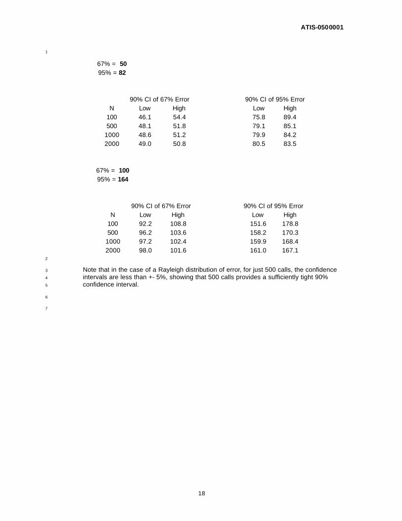
In the table below the Rayleigh distribution of error is assumed. The table shows the 26
90% confidence interval for both the 67th and 95th percentile accuracies for 2 example 27
systems with 67th percentile accuracy performance of 50m and 100m. 28
ATIS-0500001
18
1
67% = 50 95% = 82
90% CI of 67% Error 90% CI of 95% Error
N Low High Low High 100 46.1 54.4 75.8 89.4 500 48.1 51.8 79.1 85.1
1000 48.6 51.2 79.9 84.2 2000 49.0 50.8 80.5 83.5
67% = 100 95% = 164
90% CI of 67% Error 90% CI of 95% Error
N Low High Low High 100 92.2 108.8 151.6 178.8 500 96.2 103.6 158.2 170.3
1000 97.2 102.4 159.9 168.4 2000 98.0 101.6 161.0 167.1
2
Note that in the case of a Rayleigh distribution of error, for just 500 calls, the confidence 3
intervals are less than +- 5%, showing that 500 calls provides a sufficiently tight 90% 4
confidence interval. 5
6
7