mark scheme - unit f559 - instrumentation and control engineering
TRANSCRIPT

Oxford Cambridge and RSA Examinations
Principal Learning
Engineering Unit F559: Instrumentation and Control Engineering OCR Level 3 Principal Learning
Mark Scheme for January 2015

OCR (Oxford Cambridge and RSA) is a leading UK awarding body, providing a wide range of qualifications to meet the needs of candidates of all ages and abilities. OCR qualifications include AS/A Levels, Diplomas, GCSEs, Cambridge Nationals, Cambridge Technicals, Functional Skills, Key Skills, Entry Level qualifications, NVQs and vocational qualifications in areas such as IT, business, languages, teaching/training, administration and secretarial skills. It is also responsible for developing new specifications to meet national requirements and the needs of students and teachers. OCR is a not-for-profit organisation; any surplus made is invested back into the establishment to help towards the development of qualifications and support, which keep pace with the changing needs of today’s society. This mark scheme is published as an aid to teachers and students, to indicate the requirements of the examination. It shows the basis on which marks were awarded by examiners. It does not indicate the details of the discussions which took place at an examiners’ meeting before marking commenced. All examiners are instructed that alternative correct answers and unexpected approaches in candidates’ scripts must be given marks that fairly reflect the relevant knowledge and skills demonstrated. Mark schemes should be read in conjunction with the published question papers and the report on the examination. OCR will not enter into any discussion or correspondence in connection with this mark scheme. © OCR 2015

F559 Mark Scheme January 2015
3
SECTION A
Question Expected Answer Mark Rationale/Additional Guidance 1
Input devices Strain Gauge Thermistor
[1] [1]
2
Explain what is meant by the term feed-forward control Feed forward control, is a type of element or pathway within a control system ie. Process control in which changes are detected at the process input. An anticipating correction signal is applied before the process output is affected.
[1]
[1]
Allow marks for understanding shown.
3
Explain what is meant by the term data signal transmission Signal transmission is used for the element which conveys the signal from the sensing element to a receiving unit.
[1] [1]
Allow marks for understanding shown.
4
Draw the symbol for a single acting pneumatic cylinder in the space below
[2]
Diagram - award one mark for showing the correct cylinder with vent and one mark for showing the correct piston with spring.

F559 Mark Scheme January 2015
4
Question Expected Answer Mark Rationale/Additional Guidance 5
On the graph below label the diagram to show the 3db point,
the unity gain point and the slope
[3]
Award one mark for -3db point, the slope and the unity gain.
6
Sensors Examples are: (a) Pressure gauge Venturi Bourdon Gauge (b) Thermocouple Thermistor
[1] [1]
Accept any correct response.

F559 Mark Scheme January 2015
5
Question Expected Answer Mark Rationale/Additional Guidance 7
Calculate the gain for a non-inverting operational amplifier when the feedback resistor Rf is 470K and the input resistor R1 is 47K Gain = 1 + (Rf/R1) = 1 + (470/47) = 11
[1]
[1]
Do not accept error carried forward if an incorrect formula is used.
8
Correct term.
Proportional plus integral control
[1]
9
Give two benefits of a specific simulation software package used in engineering Examples of packages are: Circuit Wizard Crocodile clips Maple Sim Circuit Shop Autodesk VisSim Circuit Logix PowerESim SPICE Altium
Benefits: Allows access to activities which would otherwise be difficult to experience Overcomes the need for specialised and expensive equipment no matter what size the system is, it can be produced as a software package Always in a safe environment Learners can us the packages at any time Travelling time and expenses are cut down to a minimum
[2]
Accept any correct response. Award one mark for each correct benefit.

F559 Mark Scheme January 2015
6
Question Expected Answer Mark Rationale/Additional Guidance 10
Name two test instruments that include a visual display unit Examples: Analogue voltmeter Digital voltmeter Analogue ammeter Digital ammeter Multimeter Ohmmeter Light meter Noise/decibel meter Logic Probe Blood Pressure Monitor Digital thermometer
[2]
Award one mark for each correct test instrument. Accept any correct response.
Total for Section A [20]

F559 Mark Scheme January 2015
7
Section B Question Expected Answer Mark Rationale/Additional Guidance 1
(a)
Explain what is meant by the term Input and Output in this block diagram
Input is the term denoting either an entrance or changes which are inserted into a system and which activate or modify a process. It is an abstract concept, used in the modeling, system design and system exploitation.
Output is the term denoting either an exit or changes which exit a system and which activate/modify a process. It is an abstract concept, used in the modeling, system design and system exploitation.
[2] [2]
Allow marks for understanding shown.
1
(b)
Explain the function of the processing stage shown in the block diagram The processor deals with signals. The signal is received from the input stage and then processed. The process carries out an analysis of the signal and passes the result to the output.
[2]
Allow marks for understanding shown.
1
(c)
Name two practical applications of a control system that you have studied Examples: Temperature control Logic control Positional control PID control Servomechanism control On-Off control.
[4]
Award two marks for each correct name. Accept any other correct response.
Total [10]

F559 Mark Scheme January 2015
8
Question Expected Answer Mark Rationale/Additional Guidance 2
(a)
Overall gain when A = 20000
Overall gain = A/(1 + βA) = 20000/(1 + 0.045 x 20000) = 20000/901 = 22.2
Overall gain when A = 10000 Overall gain = A/(1 + βA)
= 10000/(1 + 0.045 x 10000) = 10000/451 = 22.17
[1]
[1]
[1]
[1]
Do not accept error carried forward if the incorrect formula is used. Accept answers between 22 and 22.5. Accept answers between 22 and 22.5.
(b)
(i)
(ii)
Overall gain when positive feedback fraction is 0.002 Overall gain = A/(1 - βA)
= 250/(1 - 0.002 x 250) = 500
Overall gain when feedback fraction is -0.004 Overall gain = A/(1 - βA)
= 250/(1 – { -0.004 x 250}) = 250/2
= 125
[1]
[1]
[1] [1]
Do not accept error carried forward if the incorrect formula is used.
2
(c)
Overall gain = A/(1 + βA)
125 = 500/(1 + 500β) (1+ 500β) = 500/125 (1 + 500β) = 4 500β = 3 β = 3/500 or 0.006
[1]
[1]
Do not accept error carried forward if the incorrect formula is used.
Total [10]

F559 Mark Scheme January 2015
9
Question Expected Answer Mark Rationale/Additional Guidance 3
(a)
What do the letters LDR and LED stand for LDR – Light Dependent Resistor LED – Light Emitting Diode
[1] [1]
3
(b)
Describe how the circuit works The LDR and the two resistors act as a potential divider. During daylight the LED will not light but as soon as darkness descends the LDR resistance goes high and current flows. This current goes into the base of the transistor, out of the emitter into the 0 volt supply Iine. The base current switches on the transistor collector current which lights up the LED. The 10K potentiometer is used to fine-tune the level of darkness required before the LED lights up. The 10K standard resistor can be changed as required to achieve the level of light required although any replacement must be at least 1K to protect the transistor from being damaged by excessive current.
[5]
Award up to five marks for a description that includes reference to:
• Potential divider • LDR • LED and 500R resistor • Transistor • 10K resistor and 10K potentiometer.
3
(c)
Explain what happens if the position of the LDR and the 10K resistor/10K potentiometer is reversed The circuit will be activated by light instead of darkness. Whenever sufficient light falls on the LDR (manually fine-tuned using the 10K potentiometer), the LED will light up.
[3]
Total [10]

F559 Mark Scheme January 2015
10
Question Expected Answer Mark Rationale/Additional Guidance 4
(a)
Draw a labelled diagram of an operational amplifier (op amp) showing the inverting input, non-inverting and output
[4]
Accept any one correct diagram. Award one mark for correct:
• op amp symbol • label of inverting input (2) • label of non-inverting input (3) • label of output (6).
4
(b)
State two main properties of an operational amplifier Infinite (large) voltage gain Infinite (large) input impedance Zero output impedance Infinite (large) Bandwidth Zero drift
[2]
Award one mark for each correct property.
Inverting

F559 Mark Scheme January 2015
11
Question Expected Answer Mark Rationale/Additional Guidance 4
(c)
Give four advantages of negative feedback in an operational amplifier Predictable and constant voltage gain Reduced distortion of the output Better frequency response giving increased bandwidth Increased stability Reduction in noise Input resistance is increased with series applied nfb Input resistance is reduced with parallel-connected nfb
[4]
Award one mark for each correct advantage.
Total [10]

F559 Mark Scheme January 2015
12
Question Expected Answer Mark Rationale/Additional Guidance 5
(a)
Explain what is meant by the term Programmable Logic Controller A programmable controller is a digitally operating electronic apparatus which uses a programmable memory for the internal storage of instructions for implementing specific functions, such as logic, sequencing, timing, counting and arithmetic, to control through digital or analogue input/output, various types of machines or process.
[1]
[1]
Allow marks for understanding shown.
5
(b)
Explain the function of any four of these components used in a Programmable Logic Controller
Central Processing Unit (CPU) is the "brain" of the PLC. The size and type of CPU will determine things like: the programming functions available, size of the application logic available, amount of memory available, and processing speed. Rack Assembly. Most medium to large PLC systems are assembled such that the individual components - CPU, Input/output, and Power Supply - are modules that are held together within a rack. In smaller PLC systems - all of these components may be contained in a single housing or "brick" - these smaller systems are sometimes referred to as "bricks" or "shoebox" PLCs. Input Assembly. Inputs carry signals from the process into the controller; they can be input switches, pressure sensors, operator inputs, etc. These are like the senses and sensors of the PLC.
[8]
Award up to two marks for a correct explanation of the function of each component.

F559 Mark Scheme January 2015
13
Question Expected Answer Mark Rationale/Additional Guidance Output Assembly. Outputs are the devices that the PLC uses to send changes out to the world. These are the actuator the PLC can change to adjust or control the process - motors, lights, relays, pumps, etc.
Many types of inputs and outputs can be connected to a PLC, and they can all be divided into two large groups - analogue and digital. Digital inputs and outputs are those that operate due to a discrete or binary change - on/off, yes/no. Analogue inputs and outputs change continuously over a variable range - pressure, temperature, potentiometer. Power Supply. The power supply provides power for the PLC system. The power supply provides internal DC current to operate the processor logic circuitry and input/output assemblies. Common power levels used are 24V DC or 120 VAC. Programming Unit. The PLC is programmed using a specialty programmer or software on a computer that can load and change the logic inside. Most modern PLCs are programmed using software on a PC or laptop computer. Older systems used a custom programming device.
Total [10]
F559 Mark Scheme January 2015
14
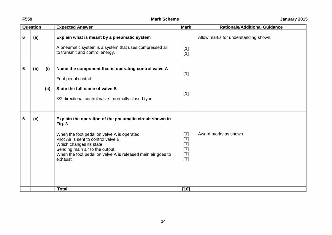
Question Expected Answer Mark Rationale/Additional Guidance 6
(a)
Explain what is meant by a pneumatic system A pneumatic system is a system that uses compressed air to transmit and control energy.
[1] [1]
Allow marks for understanding shown.
6
(b)
(i)
(ii)
Name the component that is operating control valve A Foot pedal control State the full name of valve B 3/2 directional control valve - normally closed type.
[1]
[1]
6
(c)
Explain the operation of the pneumatic circuit shown in Fig. 3 When the foot pedal on valve A is operated Pilot Air is sent to control valve B Which changes its state Sending main air to the output. When the foot pedal on valve A is released main air goes to exhaust
[1] [1] [1] [1] [1] [1]
Award marks as shown
Total [10]

F559 Mark Scheme January 2015
15
Question Expected Answer Mark Rationale/Additional Guidance 7
(a)
Give two reasons for using a computer controlled monitoring system rather than people employed to do the same task Possible that a computer is more reliable than people Monitoring can take place in dangerous situations Cost is likely to be less Less dangerous to use computer as compared to people being attacked A recording (audio/video) can be taken and used as evidence if necessary Possible reduction of insurance costs Impervious to corruption Can be used for 24 hours per day etc.
[2]
Award one mark for each correct reason.
7
(b)
Explain how monitoring systems can be used to address the following needs: Energy conservation A number of companies have introduced a real-time energy resource monitoring and control system.. With the touch of a button or the click of a mouse, users can see up-to-the-minute reports on their energy and water consumption and take action to cut their carbon footprint and reduce costly utility bills. Controlled through a simple-to-install wireless touch panel or web interface, the system helps users understand and track how they are consuming energy resources. With this information, changes can be made that will collectively result in the preservation of limited resources and reduce costs. Users can see how their energy conservation relates to their consumption footprint and how their conservation actions
[8]
Allow marks for understanding shown. Award up to two marks for an explanation of each need.
F559 Mark Scheme January 2015
16
Question Expected Answer Mark Rationale/Additional Guidance equals the number of trees they have saved or the amount of CO2 emissions they have reduced, as well as their actual savings in pounds. Fire detection control Alarm monitoring involves connecting the fire detection system to an Alarm Receiving Centre through a special modem. When the fire alarm is triggered, the modem instantly communicates the alarm to the fire brigade and dedicated person or key holder. This ensures that minimal time is wasted between the fire being detected and the fire brigade being called - which could result in lives saved. Since 2002, BS 5839 - British Standards for fire detection and fire alarm systems in buildings, recommends that all fire detection systems, which have been installed to protect property, should be able to automatically transmit a fire signal to an alarm receiving centre. This enables the building to be protected even when unoccupied. Fire detection monitoring control systems provides the following benefits: Protects your building even when unoccupied Automatically alerts the Alarm Receiving Centre within seconds Ready every second of the day, 365 days a year Quality Control and Assurance Monitoring is essential to ensure that the intended project objective can be achieved within the given time frame following the activities as planned to be carried out. Quality Control/assurance control measures are those activities you undertake to demonstrate the accuracy (how close to the real result you are) and precision (how reproducible your results are) of your monitoring. Quality Assurance (QA) generally refers to a broad plan for maintaining quality in all aspects of a program. This plan should describe how you will undertake your monitoring effort: proper documentation of all your procedures, training
F559 Mark Scheme January 2015
17
Question Expected Answer Mark Rationale/Additional Guidance of volunteers, study design, data management and analysis, and specific quality control measures. Quality Control (QC) consists of the steps you will take to determine the validity of specific sampling and analytical procedures. Quality assessment is your assessment of the overall precision and accuracy of your data, after you've run the analyses. Security Monitoring can record, playback and have archiving facilities Free from physical assault Impervious to corruption Evidence for use in legal matters Possibility in a reduction of crime on site Can be accessed from a number of remote locations Can be used for 24 hours per day etc. Video monitoring cameras have zoom, panning and angling facilities for close up observation.
Total [10]

F559 Mark Scheme January 2015
18
Question Expected Answer Mark Rationale/Additional Guidance 8
(a)
Give two limitations of computer simulation software Software can be expensive Manual construction skills are not in use No idea of what the circuit really looks like Possibility that learners could not identify a real circuit in an industrial context Computers always need to be available
[2]
Award one mark for each correct limitation
Accept other correct reasons.
8
(b)
For a computer package that you have used, describe, with the aid of a labelled diagram, how you modelled and tested a control circuit from an engineering environment
An example is shown:
Virtual Labs – Electricity
Description: "Hands-on" experiments developed by science and education experts allow learners to investigate
[8]
Award two marks for a labelled diagram. Award up to three marks for reference to modelling. Award up to three marks for reference to testing.

F559 Mark Scheme January 2015
19
Question Expected Answer Mark Rationale/Additional Guidance electricity-from conductors, insulators, resistors, capacitors, and thermal switches to circuits in doorbells. Learners practice valuable thinking skills-observation, prediction, deductive reasoning, conceptual modeling, theory building, and hypothesis testing-as they solve electricity challenges. Using Virtual Manipulation, learners can control, modify, and experiment with electrical systems in a safe and accurate manner to visualize concrete and abstract concepts.
Circuits can be viewed as they would actually appear (above), showing the flow of the charges (below left), or as a schematic (below right).

F559 Mark Scheme January 2015
20
Question Expected Answer Mark Rationale/Additional Guidance Learners can take the animated tour of the virtual laboratory for demonstrations and instructions on how to use the tools.
Total [10]

Oxford Cambridge and RSA Examinations is a Company Limited by Guarantee Registered in England Registered Office; 1 Hills Road, Cambridge, CB1 2EU Registered Company Number: 3484466 OCR is an exempt Charity OCR (Oxford Cambridge and RSA Examinations) Head office Telephone: 01223 552552 Facsimile: 01223 552553 © OCR 2015
OCR (Oxford Cambridge and RSA Examinations) 1 Hills Road Cambridge CB1 2EU OCR Customer Contact Centre Education and Learning Telephone: 01223 553998 Facsimile: 01223 552627 Email: [email protected] www.ocr.org.uk For staff training purposes and as part of our quality assurance programme your call may be recorded or monitored