marine transmission
TRANSCRIPT


2
Contents
Selection of the Fenner Belt Drive Components (Pages 3-7) Selection of the HPC Gears (Pages 7-12) Shaft Loading (Pages 12-20) Key Size and Keyways (Pages 20-21) Bearing Selection (Pages 21-22) Limits and Fits (Pages ) Design Drawings (Pages )
Parts Assembly
Appendix Input Shaft Loading Form Design Summary Form
3
As a group we will be designing a transmission system to for fill the requirements of our brief. This report will take you through the steps in which we took in order to come up with an economical design. We will cover the following; Pulley and Belt selection, Gear Selection, Shaft design, Key and Keyways, Bearing and complete drawing of the system. We had been given the following requirements:
Gear Ratio
Input Speed (rpm)
Input Power (kW)
Alternator Power
(kW)
Alternator Speed (rpm)
Degrees Minimum A (mm)
Minimum B (mm)
Minimum C (mm)
3 1050 25 7 1200 60 60 45 45
The following assumptions have been made throughout the designing process: 3 cylinder engine 20 degree involute tooth profile Pinion minimum of 20 teeth Key material has a direct yield stress of 300MPa Defining the length of the key, a safety factor of 2.0 must be used to the yield strength Centre distance of pulleys must be between 600 and 800 mm Tc is equal to zero Contact angle is close enough to 180o
Belt factor is 1.0 Tequiv has a safety factor of 2.5 on yield in shear Transmission is to last for 15 years, 250 days a year and on average of 6 hours a day Maximum yield stress in shear is 0.5 of the direct yield stress Direct yield stress is 0.6 of the ultimate tensile strength (to be used in sizing the shaft)
Selection of the Fenner Belt Drive ComponentsVisit the following site; http://www.fptgroup.com/. Click on Belt Drives and open the pdf document “Fenner Friction Belts”. Go to page 39 and this gives you a step-by-step on Belt and Pulley selection. These are the following steps that we followed:Speed RatioInput Speed / Alternator Speed = Speed Ratio1200 / 1050 = 1.14Service FactorGiven that we require a light duty start and the 3 cylinder engine is needed to run for 6 hours a day, we can find the service factor.
Service Factor = 1.1 x 1.00 =1.1We multiply by 1.00 due to the speed increase ratio.
Figure 1
Figure 2

4
Design Power Alternator Power x Service Factor = Design Power.7 x 1.1 = 7.7 kWBelt SectionGiven that we know the faster shaft to be 1200rpm and the design power to be 7.7kW. Reading of the table gives us a SPZ belt.
Minimum PulleyUsing the same information as previously we determined the minimum pulley diameter is 95mm.
Pulley Pitch DiametersGiven that our speed ratio is 1.14, the pitch diameter of pulleys of the Driver is 140mm and of the driven is 160mm.
Figure 3
Figure 4

5
Belt Length, Centre Distance and Correction FactorRestricted bounds have been given therefore the centre distance needs to fall between 600mm and 800mm. Using the same information as before, continue reading; the following centre distances fall in the bounds 664mm with a combined arc and belt length correction factor of 1.00 and 764mm with a correction factor of 1.05. We chose 764mm giving a belt length of 2000mm for the reason that the belt has a higher life span than a shorter belt. Trip rate was also calculated to show that it didn’t exceed 6/8 trips because it was given as a guide for ratios lower than 1.3; (0.0524 x small pulley pitch diameter x fast shaft) / Length of belt = Trip Rate.(0.0524 x 140 x 1200) / 2000 = 4.4016Basic Power per BeltGiven that we know the faster shaft to be 1200rpm and the small pulley pitch diameter to be 140mm. We determined the Basic Power per Belt is 3.72kW and noting that the belt speed is 10ms-1.
Figure 5

6
Speed Ratio Power IncrementFollowing the fast shaft to having 1200rpm and given that the speed ratio is 1.14 the speed ratio power increment is 0.08kW.
Corrected Power per Belt(Speed Ratio Power Increment + Basic Power per Belt) x Correction Factor = Corrected Power per Belt(0.08 + 3.72) x 1.05 = 3.99Number of Belts requiredDesign Power / Corrected Power per Belt = Number of Belts required7.7 / 3.99 = 1.929825Therefore we require 2 SPZ belts.Bore sizesWe decided on type 1 pulley so reading off the table on page 63 lead to the following pulley max bores;For the driver pulley of 140mm
42mmFor the driven pulley of 160mm
42mm
In conclusion we have determined that we require 2 belts and 2 pulleys; one of which is 140mm with a maximum bore size of 42mm and the other of 160mm with the same maximum bore size. The material of the
Figure 6
Figure 7

7
pulley is stainless steel as it is typical used in marine applications. The pulleys have the following catalogue codes; 031Z0201 and 031Z0221.
Selection of the HPC GearVisit the following site http://www.hpcgears.com/. We created a excel document to present the following information so that we could determine the most viable gear set. For the purpose of this, the brief asked us to use spur gears and start at module 3, so by clicking on Spur Gears select the type of gear “Metric (MOD)” and size “3.0 MOD”. This was used to determine which gears were available; the brief asked us to start at 20 teeth, so from there we went up in the number of teeth. But we had to make sure that it corresponded with the ratio in the brief. Those gears that didn’t have 3 times the number of teeth were eliminated. The following modules had the available gears:
MOD 3 20 21 24 25 26 28 30 32
MOD 4 20 21 22 23 24
MOD 5 20
Note that the above gears are possible pinions and there are standard and heavy-duty versions of the gears. On the catalogue page on the top it shows the available materials for the gears. For standard gears the following materials where available:
Steel 214M15 Steel 045M10 Brass Tufnol Derlin
The following were available for heavy-duty gears: 817M40 (En24) 655M13 (En 36) 080M40 (En8)
On the same site click on “Technical”, open the pdf document “General”. We created tabs to separate different material that we analysed, the following materials were used under the following tabs:
Standardo 045M10 (EN32A)
Heavy-Dutyo 817M40 (EN24)
Standard Hardenedo 045M10 (EN32A) Case Hardened
Figure 8

8
Heavy-Duty Hardenedo 655M13 (EN36) Case Hardened
Using figure 9 we could find the values of Sc and Sb.
Now open the “Gearing” pdf document. The following information can be found on this document: Speed factor for strength (Xb) Speed factor for wear (Xc) Strength factor (Y) Zone factor (Z)
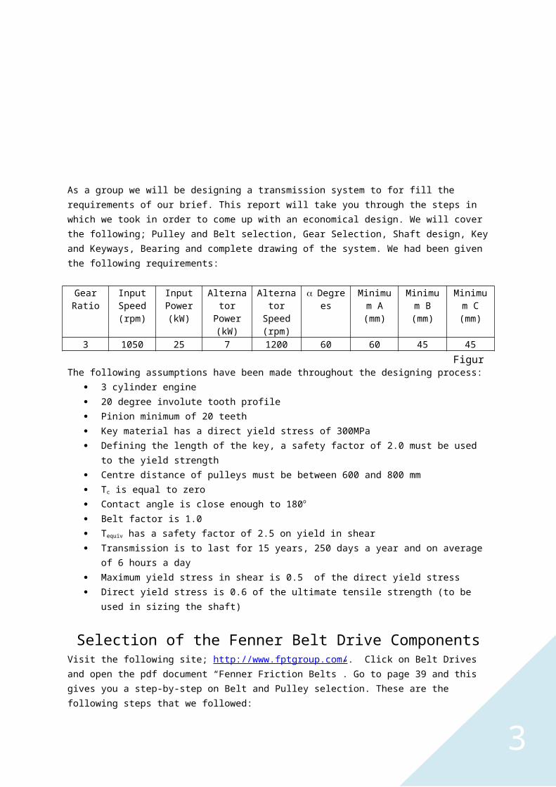
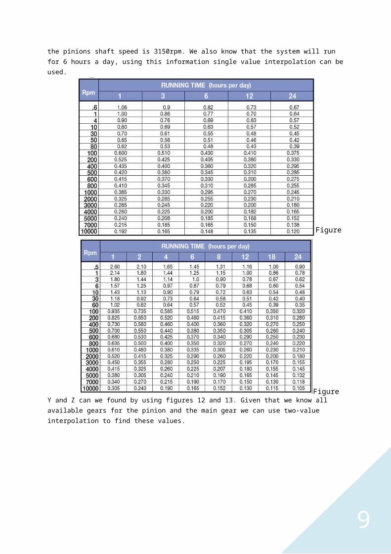
Xb and Xc can be found by using figures 10 and 11 but requires interpolation. We know the input speed to be 1050rpm and the ratio is 3:1 the pinions shaft speed is 3150rpm. We also know that the system will run for 6 hours a day, using this information single value interpolation can be used.
Figure 9
Figure 10
9
Y and Z can we found by using figures 12 and 13. Given that we know all available gears for the pinion and the main gear we can use two-value interpolation to find these values.
Figure 11
Figure 12
Figure 13

10
The following values are still needed to be found in order to find which gear set is best: Face width (F) DP Pitch factor (K)
Face width can be found on top of the catalogue pages, figure 14 shows the one for MOD 3 Standard. The values are in metric and they need to be in imperial so they needed to be converted to inches.
DP can be easy was calculated using the following formula:
Pitch Factor was calculated using the following formula:
= KAfter all the data was collected Wear and Strength were calculated so that there were comparable values.Wear equation:
Strength Equation:
Once they were calculated we divide the wear and strength by the number of teeth for each of the pinions. Ft was also calculated and inputted into the collection of data and this is to be used in Shaft Loading.The excel document shows all the data for the pinion.
Figure 15 Standard Gears data
Figure 14

11
Figure 16 Heavy-Duty Gears data
Figure 17 Standard Case Hardened
Figure 18 Heavy-Duty Case HardenedNow that we had the Wear per tooth and Strength per tooth we were able to produce graphs for each of the modules. The following graphs showed intersections:
Number of teeth
Strength per tooth & Wear per tooth
Figure 19 MOD 4 Standard Case Hardened

12
The point of intersection shows us the optimum number of teeth and strength per tooth. We chose to choose from MOD 4 standard case hardened because it would be least expensive. Now that we found the optimum strength per tooth we then multiplied it by the optimum number of teeth. Giving optimum design strength, we chose the gear that was above the optimum design strength to ensure that it was capable to withstand the forces. Then we decided to go for 20 teeth because it was the least expensive and it still fulfilled the requirements. As a further precaution we had to check that Ft was below the strength of the gear.
Shaft LoadingFirstly we took each part and their forces and broken them down into their vertical and horizontal components.
Pulley Forces Calculations
Given that we know the small pulley diameter to be 140mm, using the Fenner catalogue shown previously in the Selection of the Fenner Belt Drive Components section. It gives us P to be 25N.
TS = 16P = 16 x 25 = 400 NTD = 2TS sin (/2) n, is close to 180o
So sin (180/2) = 1
Number of teeth
Strength per tooth & Wear per tooth
Figure 20 MOD 4 Heavy-Duty Case Hardened
Figure 21

13
TD = 2TSn = 2 x 400 x 2 = 1600 NTV = 1600sin60 = 1385.640646 NTH = 1600cos60 = 800 N
Gear Forces Calculations
Ft = 1804.477817 NFV = 1804.477817sin20 = 617.1677616 NFH = 1804.477817cos20 = 1695.654489 NThese are the component forces of Ft.
Gear Shaft - Vertical
Gear Torque Calculations
(1050 x 2) / 60 = 109.955743T = /P25000 / 109.955743 = 227.36 Nm
Figure 22
Figure 23All distances are in mmClockwise is positive

14
Force DiagramShear Force DiagramBending Force Diagram

15
Force DiagramBending Moments Diagram Shear Force Diagram

16
Gear Resultant Bending Diagram
902 + 522 = 104 Nm
602 + 16.42 = 62 Nm
Nm 104 62
x T B1 F B2
Teq = M2 + T2
Teq = 1042 + 2272 = 250 Nm
Teq = 622 + 2272 = 235 Nm
max = Yield Strength x 0.6Alloy Steel = 600 MN/m2
Low Carbon Steel = 420 MN/m2
Mild Steel = 308 MN/m2
Stainless Steel = 700 MN/m2
SF = 2.5
d = 1.1 3 16 x Teq x SF x max
Alloy Steel1.1 3 16 x 250 x 2.5 = 22.8 mm x 0.6 x 600 x 106
Low Carbon Steel1.1 3 16 x 250 x 2.5 = 25.7 mm x 0.6 x 420 x 106
Mild Steel1.1 3 16 x 250 x 2.5 = 28.5 mm x 0.6 x 308 x 106
Stainless Steel1.1 3 16 x 250 x 2.5 = 21.7 mm x 0.6 x 700 x 106
The Above diameters are the minimum if the shaft is to be made from the different materials.

17
Force DiagramShear Force DiagramBending Moments Diagram

18
Force DiagramShear Force DiagramBending Moments Diagram

19
Pinion Torque Calculations
(3150 x 2) / 60 = 329.867229T = /P25000 / 329.867229 = 75.79 Nm
Resultant Bending Diagram
15.42 + 42.42 = 45 Nm
Nm 45
x B1 F B2
Teq = M2 + T2
Teq = 452 + 75.792 = 88 Nm
d = 1.1 3 16 x Teq x SF x max
Alloy Steel1.1 3 16 x 88 x 2.5 = 16.1 mm x 0.6 x 600 x 106
Low Carbon Steel1.1 3 16 x 88 x 2.5 = 18.1 mm x 0.6 x 420 x 106
Mild Steel1.1 3 16 x 88 x 2.5 = 20.1 mm x 0.6 x 308 x 106
Stainless Steel1.1 3 16 x 88 x 2.5 = 15.3 mm x 0.6 x 700 x 106
The Above diameters are the minimum if the shaft is to be made from the different materials.

20
All calculated are diameters have been rounded to the nearest upper 0.1 because the diameter cannot be lower than the actual calculated value. So in conclusion we have multiplied the yield strength of the material by 0.6 as requested in the brief. This led us to determine minimum diameters for the gear and pinion shaft for the following materials; Low carbon steel, mild steel, alloy steel and stainless steel. We have chosen to use alloy steel for the reason that it is the second cheapest out of the four of them. Also it has the second smallest diameter, so that we can reduce material use and it’s the most ideal for the available sizes there are for the gears and the bearings. This gives us the following minimum diameters of 22.8mm and 16.1 for the gear and pinion shaft.
Key Size and KeywaysWe have chosen to use a flat key. We used figure 42 to give us the dimensions of the key and keyway.
As for the dimension of the gear shaft is 30mm and for the pinion shaft is 25mm, the following dimensions are for the key and the keyway (width x depth):
Pinion Shaft Key 6 x 6 Keyway 6 x 2.8
Gear Shaft Key 8 x 7 Keyway 8 x 3.3
We then defined L with strength calculation:Direct Yield Strength = 300 MN/m2
A safety factor of 2.0 is applied to the yield strength.
Lengths of the keysEquation:
L = ( 2 x T ) / ( b x D x Ss )
Gear keyL = ( 2 x 227 ) / ( 8 x 10-3 x 25 x 10-3 x 0.5 x 300 x 106
) = 15.13 mm = 15.2 mm
Pinion keyL = ( 2 x 75.79 ) / ( 6 x 10-3 x 20 x 10-3 x 0.5 x 300 x 106
) = 8.421 mm = 8.5 mmThese are the required length of keys in order to overcome the failure due to shear forces.

21
Pinion ShaftT = (60 x P) / (2 x n) (60 x 25000) / (2 x 3150) = 75.79L > (4T x N) / (Sy x D x b)L = (4 x 75.79 x 2) / (300 x 106 (0.025 x 0.006)) = 0.0134738 x 1000 = 13.5mm
Gear ShaftT = (60 x P) / (2 x n) (60 x 25000) / (2 x 1050) = 227.36L > (4T x N) / (Sy x D x b)L = (4 x 227.36 x 2) / (300 x 106 (0.03 x 0.008)) = 0.025262 x 100 = 25.3 mm
These are the required length of keys that are necessary to overcome the failure due to the compressive stresses. We have chosen to make the length according to the failure due to the compressive stress. There is no need for a key for the pulley because it is a taper lock pulley which is governed by the bush so it fastens around the shaft. For intense and purposes in the design process the bore size of the pulley is to be made the same as the shaft diameter.
SealIn order to protect the bearings from moisture, other contaminants and the loss of lubrication we’ve selected to use V-ring seal because it is easy to fit and is able for grease or oil lubrication.
LubricationWe selected a V-ring seal which is able to apply both lubricants; for this purpose we chose to use oil as there are many methods in applying it. We are mostly considering the Bath method as it is simple and acts independently to the seal. The purpose for applying lubrication to the bearing is to protect the surface from corroding and to reduce the magnitude of friction and heat generation.
Bearing SelectionWe decided on using double-row deep-grove ball bearing because it had the best overall when comparing the following factors; radial load capacity, thrust load capacity and misalignment capability.Bearing Calculations
Bearing 1 Resultants
21682 + 19782 = 2934.74 N
308.52 + 8482 = 902.37 N
Bearing 2 Resultants
12092 + 3282 = 1252.70 N
308.52 + 8482 = 903.37 N

22
Gear ShaftB1R = 2934.74 NB2R = 1252.70 NPinion ShaftB1R = 903.37 NB2R = 903.37 N
L10h = 6hour x 250days x 15years = 225000hoursn = 1050 / 3150 rpmp = 3 chose to use ball bearingP = Load on the bearingC/P = minimum Duty of the bearingC = minimum dynamic loadGear shaftB1 Cduty = ((225000 x 60 x 1050) / (106))1/3 = 11.23, 11.23 x 2934.74 = 32966.84 NB2 Cduty = ((225000 x 60 x 1050) / (106))1/3 = 11.23, 11.23 x 1252.70 = 14067.82 NPinion ShaftB1 Cduty = ((225000 x 60 x 3150) / (106))1/3 = 34.90,
34.90 x 903.37 = 31531.68 NB2 Cduty = ((225000 x 60 x 3150) / (106))1/3 = 34.90,
34.90 x 903.37 = 31531.68 NThe values calculated for Cduty must be compared to the dynamic load in the catalogue on the following website http://www.skf.com/uk/index.html.
The following bearings were selected: B1 gear shaft 4305 ATN9 B2 gear shaft 4205 ATN9 B1 pinion shaft 4304 ATN9 B2 pinion shaft 4304 ATN9

23
Limits and Fits