marine & offshore solution guide - mtu-online-shop.com · marine & offshore solution guide...
TRANSCRIPT

Power. Passion. Partnership.
Marine & Offshore Solution GuideDiesel Engines, Propulsion Systems, Edition 1/18 Generator Sets, Automation valid from 01/2018
© N
orth
rop
Gru
mm
an©
Øyv
ind
Hag
en/
Stat
oil
Solution Guide I Marine & Offshore I 3
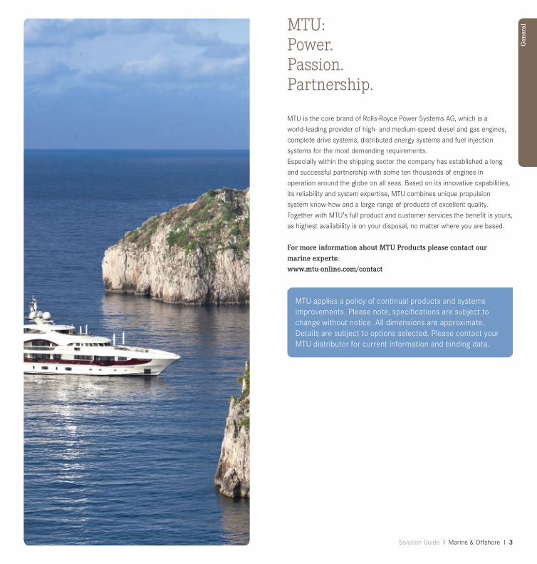
MTU:Power. Passion. Partnership.
MTU is the core brand of Rolls-Royce Power Systems AG, which is a
world-leading provider of high- and medium-speed diesel and gas engines,
complete drive systems, distributed energy systems and fuel injection
systems for the most demanding requirements.
Especially within the shipping sector the company has established a long
and successful partnership with some ten thousands of engines in
operation around the globe on all seas. Based on its innovative capabilities,
its reliability and system expertise, MTU combines unique propulsion
system know-how and a large range of products of excellent quality.
Together with MTU’s full product and customer services the benefit is yours,
as highest availability is on your disposal, no matter where you are based.
For more information about MTU Products please contact our marine experts: www.mtu-online.com/contact
Gen
eral
MTU applies a policy of continual products and systems improvements. Please note, specifications are subject to change without notice. All dimensions are approximate. Details are subject to options selected. Please contact your MTU distributor for current information and binding data.

4 I Marine & Offshore I Solution Guide Solution Guide I Marine & Offshore I 5
04 Content
Selection guideline06 Marine and offshore service & supply08 Offshore exploration & production
Power range10 Power range marine and offshore service & supply14 Power range offshore exploration & production
16 MTU rating philosophy
17 Power definition
18 Explanation engine and genset designation
Engines and gensets overview22 Series 6023 Series 39624 Series 200026 Series 400028 Series 116329 Series 800030 Genset 200032 Genset 4000
Engines and gensets marine and service & supply34 Engines for diesel-mechanic propulsion 42 Engines and gensets for on-board power generation and
diesel-electric propulsion
Engines and gensets for offshore exploration & production
50 Engines and gensets for offshore power generation Systems solutions marine and service & supply58 System expertise60 Combined propulsion solutions62 Marine gensets64 MTU Callosum - integrated ship automation system66 Standardized propulsion automation systems
– BlueVision|NewGeneration68 Standardized propulsion automation systems smartline,
blueline, bluevision 70 Standardized and system solutions genoline
Systems solutions offshore exploration & production72 Offshore generator sets74 MTU P-engines for ATEX zone 2 76 Redundant controller for fire pump drive systems
78 Parts & Service
88 Exhaust emissions89 IMO90 US EPA91 EU92 Examples for emission stages93 Abbreviations
95 Conversion table
Con
tent
s

6 I Marine & Offshore I Solution Guide Solution Guide I Marine & Offshore I 7
Selection guidelineMarine and offshore service & supply
MTUapplicationgroup> 1A 1B 1D 1DSMechanicalpropulsionengines
Yacht Planing Semi planing Small displacement Large displacement > 120 ft. Cargo Inland freighters
ships Coastal ships
& tankers Sea-river ships
Passenger Tourist boats
ships Passenger ferries
Cabin cruisers
RoPax Double-ended ferries
ferries Fast ferries < 50 m
Fast ferries > 50 m
Tugs & Tow & push boats
push Harbour tugs
boats Coastal tugs
Escort tugs
Offshore Crew boats
vessels & Offshore supply vessels
crew boats Anchor handling tugs
Pilot boats
Trawler (fishing vessels)
Firefighting vessels
Rescue vessels Research vessels Dredgers Cable laying vessels
MTUapplicationgroup> 1A 1B 1D 1DSMechanicalpropulsionengines
Marine Fast attack crafts Naval Corvettes Vessels Frigates and Destroyers Amphibious crafts Large amphibious and
support vessels Mine countermeasure
vessels
Patrol Small patrol crafts boats Coastal patrol crafts Large patrol vessels > 120 ft.
The guideline on page 6 - 7 gives a rough overview which MTU application
groups can be considered for which type of vessel or business model.
To allocate which MTU application group suits your demands best, the
intended annual usage and the expected load profile have to be
considered.
MTUapplicationgroup> 3A/3B 3A/3BPowergenerationand 50Hz 60Hzdiesel-electricpropulsion
On-board powergen
Diesel-electric propulsion
Emergency powergen
Gen
eral

8 I Marine & Offshore I Solution Guide Solution Guide I Marine & Offshore I 9
Selection guidelineOffshore exploration & production
Diesel engines for:- Heavy lift vessel
- Diving support vessel
- Pipe-laying vessel
- Cable-laying vessel
- Subsea support vessel
- Well intervention vessel
Accommodation vessel
- Drill ship
- Wind converter platform
- Fixed platform
- Tension-leg platform
- Jack-up rig
- Spar
- NUI
- Conductor support system
- Compliant power
- FLNG
- Semi-submersible
- FPSO
- Windfarm substation platforms
MTUapplicationgroup> 3A 3B 3C
Powergeneration 50Hz/60Hz 50Hz/60Hz 50Hz/60Hz Power generation x x x
Electric firepump drives x x
Electric drilling drives x x
Power generation - constant speed
Diesel engines for power generation
Gen
eral
The guideline above gives a rough overview which MTU application groups
can be considered for which type of vessel or business model. To allocate
which MTU application group suits your demands best, the intended
annual usage and the expected load profile have to be considered.

10 I Marine & Offshore I Solution Guide Solution Guide I Marine & Offshore I 11
Power range Marine and offshore service & supply
1D- DieselenginesforfastvesselswithintermittentloadfactorsAverage load: ≤ 60 % of rated power; Rating definition: ICFN, fuel stop;
Typical annual usage: 3000 hours*
1DS- DieselenginesforfastvesselswithlowloadfactorsAverage load: ≤ 60% of rated power; Rating definition: ICFN, fuel stop;
Typical annual usage: 1500 hours* * MTU application groups (page 6-9) only indicate which MTU diesel engine suits your demands best. For your type of vessel, you can also choose engines from other MTU application groups than stated in the selection guideline.
1A- Dieselenginesforvesselswithunrestrictedcontinuous operationAverage load: 70 - 90 % of rated power; Rating definition: ICFN, fuel stop;
Typical annual usage: unrestricted*
1B- DieselenginesforfastvesselswithhighloadfactorsAverage load: 60 - 80 % of rated power; Rating definition: ICFN, fuel stop;
Typical annual usage: 5000 hours*
Main propulsion:
Engine power in kW
Engi
ne S
erie
s
500
1000
1500
2000
2500
3000
3500
4000
4500
8000
1163
396
2000
4000
60
4500
5000
5500
6000
6500
7000
7500
8000
8500
9000
Gen
eral
Engine power in kW
Engines 1A 1B 1D 1DS60 261-373 354-447 – 466-615
2000 400-800 720-1440 810-1630 932-1939
396 – 1000-2000 – –
4000 746-2240 1920-3600 – 2340-4300
1163 – 4800-6000 5200-6500 5920-7400
8000 – 7280-9100 – 8000-10000

12 I Marine & Offshore I Solution Guide Solution Guide I Marine & Offshore I 13
Power range Marine and offshore service & supply
Marine on-board power generation, diesel-electric drives and generator sets:
3A/3B-Dieselenginesforonboardpowergenerationand diesel-electricdriveContinuous operation 50 Hz; Rating definition: ICXN, 10% overload capab.
Continuous operation 60 Hz; Rating definition: ICXN, 10% overload capab. MTU application groups (page 6-9) only indicate which MTU diesel engine suits your demands best. For your type of vessel, you can also choose engines from other MTU application groups than stated in the selection guideline.
Engine power in kW
Engines 3A/3B 3A/3BFrequency 50Hz 60Hz60 271-322 271-370
2000 332-770 400-930
396 680-1030 790-1200
4000 760-2600 895-3015
Genset power in kWe*
Gensets 3A/3B 3A/3BFrequency 50Hz 60HzMG 2000 310-730 370-880
MG 4000 720-1690 850-2150 * alternator efficiency of 96% considered, excluding parasitic losses
Engine power in kW
Engi
ne S
erie
s
2000
60
500
1000
1500
396
1500
2000
2500
3000
Gen
eral
4000
14 I Marine & Offshore I Solution Guide Solution Guide I Marine & Offshore I 15
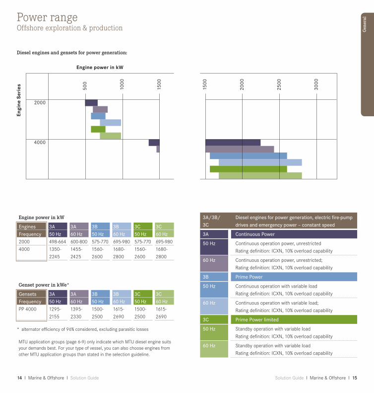
Power rangeOffshore exploration & production
Engine power in kW
Engines 3A 3A 3B 3B 3C 3CFrequency 50Hz 60Hz 50Hz 60Hz 50Hz 60Hz2000 498-664 600-800 575-770 695-980 575-770 695-980
4000 1350- 1455- 1560- 1680- 1560- 1680-
2245 2425 2600 2800 2600 2800
Genset power in kWe*
Gensets 3A 3A 3B 3B 3C 3CFrequency 50Hz 60Hz 50Hz 60Hz 50Hz 60HzPP 4000 1295- 1395- 1500- 1615- 1500- 1615-
2155 2330 2500 2690 2500 2690 * alternator efficiency of 96% considered, excluding parasitic losses
MTU application groups (page 6-9) only indicate which MTU diesel engine suits your demands best. For your type of vessel, you can also choose engines from other MTU application groups than stated in the selection guideline.
Diesel engines and gensets for power generation:
Engi
ne S
erie
s
Engine power in kW
500
1000
1500
2000
4000
1500
2000
2500
3000
Gen
eral
3A/3B/3C
Dieselenginesforpowergeneration,electricfire-pumpdrivesandemergencypower–constantspeed
3A ContinuousPower
50Hz Continuous operation power, unrestricted
Rating definition: ICXN, 10% overload capability
60Hz Continuous operation power, unrestricted;
Rating definition: ICXN, 10% overload capability
3B PrimePower
50Hz Continuous operation with variable load
Rating definition: ICXN, 10% overload capability
60Hz Continuous operation with variable load;
Rating definition: ICXN, 10% overload capability
3C PrimePowerlimited
50Hz Standby operation with variable load
Rating definition: ICXN, 10% overload capability
60Hz Standby operation with variable load
Rating definition: ICXN, 10% overload capability

16 I Marine & Offshore I Solution Guide Solution Guide I Marine & Offshore I 17
Gen
eral
Power definitionThe rated power of diesel engines stated in this sales program corresponds
to ISO 3046-1:2002 (E) and ISO 15550:2002 (E). The power produced at
the flywheel will be within the tolerance of 3 % - according to
ISO 15550:2002 (E) – up to 25°C (77°F) combustion air temperature
measured at the air cleaner inlet and up to 25°C (77°F) sea or raw water
temperature measured at the seawater pump suction inlet, unless other
values mentioned explicitly.
ICFN = ISO standard (continuous) fuel stop power
ICXN = ISO standard (continuous) power exceedable by 10 % (ratings also
apply to ISO 8665 and SAE J1228 standard conditions)
Barometric pressure: 1000 mbar
Site altitude above sea level: 100 m
Fuel specification: EN 590 to ASTM D 975-00
(Fuel consumption [with all pumps] in accordance with DIN ISO 3046
[except Series 60], values stated for IMO certification.)
General reference conditions for diesel engines and generator sets:
— Intake air temperature 25°C
— Sea water temperature 25°C
— Charge air coolant inlet temperature 45°C up to 65°C without deration
All engines are designed and built according to classification requirements, certificate on request.Classification with:
— Unrestricted service for engines with 10% overload capacity
— Restricted service for engines without overload capacity
Power definition
A
B
C/D/DS
Unrestricted/Heavy duty70-90% load factor
High load/Medium duty60-80% load factor
Intermitted an low load/short time duty< 60% load factor
Load factor:Applicationindex: e.g.
1A, 3A, 1DS
MTU rating philosophy
MTU is working hard to meet and even exceed the increasing demands
of ship owners and operators for cost-effective and eco-friendly solutions.
One example is the engine TBO (Time Between Overhauls) which we
optimize on the basis of field data analysis and close inspection of engines
and components that have already proven their reliability in field operation.
Depending on the analysis results, we extend maintenance and TBO
intervals keeping safe operation assured.
MTU offers product lines specifically tailored to customer requirements.
Some are laid out for high power density with ideal power-to-weight-ratios
(application groups C, D and DS). Other product lines are specifically
configured to achieve maximum service life at lower power densities. These
are suitable for applications involving high load factors and runtimes up to
8,000 hours per year (application groups A and B).
Powerdensity
Load profileLoad factor
Utilization p.a. TBO
Max. Max.
Max.

18 I Marine & Offshore I Solution Guide Solution Guide I Marine & Offshore I 19
Explanation of the engine designation
Explanation of the genset designation
Series 396 – Example:
16 V 396 TE 7 4 LAdditional engine features
Design index
Application segment
Turbocharged/charge-air cooling
Series
Cylinder configuration: V = V-engine
No. of cylinders
Series 2000 / 4000 / 1163 / 8000 – Example:
16 V 4000 M7 3 LAdditional engine features
Design index
Application segment
Application: M = Marine P = Offshore
Series
Cylinder configuration: V = V-engine R = in-line
No. of cylinders
Turbochargedengines/gensetswithSeparate-circuit charge-air cooling 60 / 2000 P / 4000 P / 1163
Split-circuit charge-air cooling 2000 M / 4000 M / 396 TE /
8000 M
Additionalengine/gensetsfeaturesPower uprated L
Power/speed reduced R
Frequency A or F (50 Hz)
B or S (60 Hz)
Engi
ne d
esig
nati
on
Generator sets with Series 2000 / 4000 – Example:
MG 08 V 4000 M3 3 FFrequency/additional engine feature
Design index
Application segment
Application: M = Marine P = Offshore
Series
Cylinder configuration: V = V-engine R = in-line
No. of cylinders
Type of genset: MG = Marine Genset PP = Offshore PowerPack

20 I Marine & Offshore I Solution Guide Solution Guide I Marine & Offshore I 21
Engines overview
Engi
nes
over
view

22 I Marine & Offshore I Solution Guide Solution Guide I Marine & Offshore I 23
Overview Series 60
Marine and offshore service & supply
Engine Displacement Dimensions,max. Mass,max.Cylinder config.: Total displac. L x W x H (dry)6 Cyl./ in-line l (cu in) mm (in) kg (lbs.)S60 14.0 1850 x 1035 x 1160 1633 (855) (73 x 41 x 46) (3600)
External heat exchanger version as standard, optional engine mounted.
L W
H
Engi
nes
over
view
Overview Series 396
Marine and offshore service & supply
Engine Displacement Dimensions,max. Mass,max.Cylinder config.: Total displac. L x W x H (dry)90°V l (cu in) mm (in) kg (lbs.)8V 396 31.7 2005 x 1525 x 1540 3800 (1933) (79 x 60 x 61) (8377)
12V 396 47.5 2535 x 1525 x 1695 4900 (2900) (100 x 60 x 67) (10803)
16V 396 63.4 3070 x 1530 x 1660 6140 (3868) (121 x 60 x 65) (13536)
External heat exchanger version as standard, optional engine mounted.

24 I Marine & Offshore I Solution Guide Solution Guide I Marine & Offshore I 25
Overview Series 2000
Engi
nes
over
view
Marine and offshore service & supply
Engine Displacement Dimensions,max. Mass,max.Cylinder config.: Total displac. L x W x H (dry)90°V l (cu in) mm (in) kg (lbs.)8V 2000 15.9 1435 x 1280 x 1315 1870M41/51/61 (970) (57 x 50 x 52) (4123)
12V 2000 23.9 2105 x 1400 x 1290 2756M41/51/61/70 (1458) (83 x 55 x 51) (6064)
16V 2000 31.8 2525 x 1425 x 1290 3270M41/51/61/70 (1943) (99 x 56 x 51) (7209)
Engine mounted heat exchanger as standard, external heat exchanger version as option.
8V 2000 17.9 1416 x 1130 x 1200 1970M72/84/93/94 (1093) (56 x 45 x 47) (4343)
10V 2000 22.3 1604 x 1165 x 1347 2305M72/86/96 (1361) (63 x 46 x 53) (5082)
12V 2000 26.8 1870 x 1295 x 1350 2810M72/86/96 (1635) (74 x 51 x 53) (6195)
16V 2000 35.7 2258 x 1318 x 1455 3450M72/86/96 (2179) (89 x 52 x 57) (7607)
Engine mounted heat exchanger as standard.
Offshore exploration & production
Engine Displacement Dimensions,max. Mass,max.Cylinder config.: Total displac. L x W x H (dry)90°V l (cu in) mm (in) kg (lbs.)12V 2000 23.9 2165 x 1340 x 1490 2650P62/82 (1458) (85 x 53 x 58) (5842)
16V 2000 31.8 2502 x 1430 x 1495 3060P62/82 (1943) (99 x 53 x 59) (6746)
External heat exchanger version as standard.

26 I Marine & Offshore I Solution Guide Solution Guide I Marine & Offshore I 27
Overview Series 4000
Offshore exploration & productionLong stroke (210 mm)
Engine Displacement Dimensions,max. Mass,max.Cylinder config.: Total displac. L x W x H (dry)90°V l (cu in) mm (in) kg (lbs.)12V 4000 57.2 2530 x 1590 x 2065 7300P63/83 (3491) (100 x 63 x 81) (16093)
16V 4000 76.3 3000 x 1590 x 2065 8800P63/83 (4656) (118 x 63 x 81) (19400)
20V 4000 95.4 3470 x 1590 x 2065 10680P63/83 (5822) (137 x 63 x 81) (23545)
External heat exchanger version as standard.
Engi
nes
over
view
Marine and offshore service & supplyStandard stroke (190 mm)
Engine Displacement Dimensions,max. Mass,max.Cylinder config.: Total displac. L x W x H (dry)90°V l (cu in) mm (in) kg (lbs.)12V 4000 51.7 2870 x 1850 x 2185 8410M53B/73/93 (3155) (113 x 73 x 86) (18541)
16V 4000 69.0 3510 x 1850 x 2185 9890M53B/73/93 (4210) (138 x 73 x 86) (21803)
20V 4000 86.2 4040 x 1470 x 2440 12900M53B/73/93 (5260) (159 x 58 x 96) (28439)
Engine mounted heat exchanger as standard.
Long stroke (210 mm)
8V 4000 M23/24/ 38.2 2386 x 1615 x 1972 5710M33/53/54/63 (2331) (94 x 64 x 78) (12588)
12V 4000 M23/ 57.2 2740 x 1570 x 2370 7600M24/33/34/53/ (3491) (108 x 62 x 93) (16755)M54/63/6416V 4000 M23/ 76.3 3270 x 1570 x 2370 8950M24/33/34/43/ (4656) (129 x 62 x 93) (19731)M53/54/63/64
Engine mounted heat exchanger as standard, external heat exchanger version as option.

28 I Marine & Offshore I Solution Guide Solution Guide I Marine & Offshore I 29
Marine and offshore service & supply
Engine Displacement Dimensions,max. Mass,max.Cylinder config.: Total displac. L x W x H (dry)60°V l (cu in) mm (in) kg (lbs.)16V 1163 186.1 4687 x 1918 x 3040 20590 (11357) (185 x 76 x 120) (45393)
20V 1163 232.7 5353 x 1918 x 3040 25000 (14200) (211 x 76 x 120) (55116)
External heat exchanger version as standard.
Overview Series 8000
Marine and offshore service & supply
Engine Displacement Dimensions,max. Mass,max.Cylinder config.: Total displac. L x W x H (dry)48°V l (cu in) mm (in) kg (lbs.)16V 8000 278 5698 x 2040 x 3375 42000 (16965) (224 x 80 x 133) (92594)
20V 8000 347.4 6645 x 2040 x 3375 49600 (21200) (262 x 80 x 133) (109348)
External heat exchanger version as standard.
Engi
nes
over
view
Overview Series 1163

30 I Marine & Offshore I Solution Guide Solution Guide I Marine & Offshore I 31
Marine and offshore service & supply
Gensetmodel Displacement Dimensions,max. Mass,max. Total displac. L x W x H (dry) l (cu in) mm (in) kg (lbs.)MG08V 2000 15.9 2900 x 1680 x 1550 3950M51/41 (970) (114 x 66 x 61) (8708)
MG12V 2000 23.9 3550 x 1680 x 1680 5400M51/41 (1458) (140 x 66 x 66) (11905)
MG16V 2000 31.8 3900 x 1680 x 1760 6300M51/41 (1943) (154 x 66 x 70) (13890)
Engine mounted heat exchanger version as standard, optional external cooling.
Engi
nes
over
view
Overview Series 2000 genset

32 I Marine & Offshore I Solution Guide Solution Guide I Marine & Offshore I 33
Offshore exploration & production Long stroke (210 mm)
Gensetmodel Displacement Dimensions,max. Mass,max. Total displac. L x W x H (dry) l (cu in) mm (in) kg (lbs.)PP12V4000 57.2 4850 x 1950 x 2450 14500P63/83 (3491) (191 x 77 x 96) (31970)
PP16V4000 76.3 5720 x 1950 x 2450 18500P63/83 (4656) (225 x 77 x 96) (40786)
PP20V4000 95.4 6950 x 1950 x 2450 24300P63/83 (5822) (274 x 77 x 96) (53575)
Engi
nes
over
view
Overview Series 4000 genset
Marine and offshore service & supplyLong stroke (210 mm)
Gensetmodel Displacement Dimensions,max. Mass,max. Total displac. L x W x H (dry) l (cu in) mm (in) kg (lbs.)MG08V 4000 38.2 4250 x 1825 x 2225 11240M23/24/33 (2331) (167 x 72 x 87) (24780)
MG12V 4000 57.2 4700 x 1825 x 2285 14000M23/24/33/34 (3491) (185 x 72 x 90) (30865)
MG16V 4000 M23/ 76.3 5700 x 1965 x 2285 18500M24/33/34/43 (4656) (225 x 78 x 90) (40786)
External heat exchanger version as standard, optional engine mounted.

34 I Marine & Offshore I Solution Guide Solution Guide I Marine & Offshore I 35
Diesel engines for mechanic propulsion
mec
han
ic p
ropu
lsio
n

36 I Marine & Offshore I Solution Guide Solution Guide I Marine & Offshore I 37
Diesel engines for mechanic propulsion
261 kW - 1342 kW(350 bhp - 1800 bhp)
Enginemodel Ratedpower Application ICFN group kW bhp rpm 1A 1B 60 261 350 1800 ■
60 280 375 1800 ■
60 298 400 1800 ■
60 317 425 1800 ■
60 336 450 1800 ■
60 354 475 1800 ■
60 354 475 2100 ■
60 373 500 1800 ■
60 399 535 2100 ■
60 447 600 2100 ■
60 466 625 2300
60 499 670 2300
60 552 740 2300
60 597 800 2300
60 615 825 2300
8V 2000 M61 400 536 1800 ■
12V 2000 M61 600 805 1800 ■
8V 2000 M72 720 966 2250 ■
12V 2000 M70 788 1057 2100 ■
16V 2000 M61 800 1070 1800 ■
8V 2000 M84 810 1085 2450
8V 2000 M84L 895 1200 2450
10V 2000 M72 900 1205 2250 ■
8V 2000 M94 932 1250 2450
10V 2000 M86 1015 1360 2450
16V 2000 M70 1050 1408 2100 ■
12V 2000 M72 1080 1450 2250 ■
10V 2000 M96 1120 1500 2450
10V 2000 M96L 1193 1600 2450
12V 2000 M86 1268 1700 2450
12V 2000 M96 1342 1800 2450
* IMO III solution on request ** emission stage has been superseded, local exemptions may apply
Fuelconsumption Emissionsatratedpower Optimum Optimizationg/kWh l/h g/kWh IMO* EPA EU 206 65 REQ. II T2c** –
205 69 REQ. II T2c** –
198 71 REQ. II T2c** –
197 75 REQ. II T2c** –
196 80 REQ. II T2c** –
196 84 REQ. II T2c** –
203 87 REQ. II T2c** –
196 88 REQ. II T2c** –
205 98 REQ. II T2c** –
210 113 REQ. II T2c** –
216 121 REQ. II T2c** –
211 127 REQ. II T2c** –
215 143 REQ. II T2c** –
218 157 REQ. II T2c** –
219 162 REQ. II T2c** –
205 99 199 II T2c** CCNR II
213 153 200 II T2c** CCNR II
212 184 195 II T2c** IIIA
209 198 197 I** T2c** –
207 200 201 II T2c** CCNR II
218 213 192 II T2c** CCNR II
227 245 194 II T2c** –
215 233 197 II T2c** IIIA
226 254 195 II T2c** CCNR II
219 268 192 II T3r RCD 2
212 267 195 II T2c** –
208 271 195 II T2c** IIIA
220 297 192 II T3r RCD 2
223 320 192 II T3r RCD 2
214 326 196 II T3r RCD 2
215 347 195 II T3r RCD 2
Applicationgroup1D 1DS
■
■
■
■
■
■
■
■
■
■
■
■
■
Ser
ies
60S
erie
s 20
00
mec
han
ic p
ropu
lsio
n

38 I Marine & Offshore I Solution Guide Solution Guide I Marine & Offshore I 39
Diesel engines for mechanic propulsion
746 kW - 2160 kW(1000 bhp - 2895 bhp)
Enginemodel Ratedpower Application ICFN group kW bhp rpm 1A 1B 12V 2000 M96L 1432 1920 2450
16V 2000 M72 1440 1930 2250 ■
16V 2000 M86 1630 2186 2450
16V 2000 M96 1790 2400 2450
16V 2000 M96L 1939 2600 2450
8V 396 TE74L 1000 1341 1900 ■
12V 396 TE74L 1500 2012 1900 ■
16V 396 TE74L 2000 2682 1900 ■
8V 4000 M53R 746 1000 1600 ■
8V 4000 M54R 746 1000 1600 ■
8V 4000 M54 895 1199 1800 ■
8V 4000 M53 920 1234 1800 ■
8V 4000 M63 1000 1340 1800 ■
12V 4000 M53R 1140 1529 1600 ■
12V 4000 M54 1193 1600 1800 ■
12V 4000 M53 1380 1851 1800 ■
12V 4000 M64 1398 1875 1800 ■
16V 4000 M53R 1492 2000 1600 ■
12V 4000 M63 1500 2012 1800 ■
16V 4000 M53R 1520 2038 1600 ■
16V 4000 M54 1685 2260 1800 ■
16V 4000 M53 1840 2467 1800 ■
16V 4000 M63R# 1920 2575 1600 ■
12V 4000 M73 1920 2575 1970 ■
16V 4000 M64 1999 2681 1800 ■
16V 4000 M63 2000 2680 1800 ■
12V 4000 M73L 2160 2895 2050 ■
* IMO III solution on request ** emission stage has been superseded, local exemptions may apply *** until 30.09.2017# 1840 kW with 1600 rpm available on request
Fuelconsumption Emissionsatratedpower Optimum Optimizationg/kWh l/h g/kWh IMO* EPA EU 216 373 193 II T3r RCD 2
206 357 195 II T2c** IIIA
217 426 193 II T3r RCD 2
215 463 190 II T3r RCD 2
216 505 190 II T3r RCD 2
217 261 213 I** – –
214 387 203 I** – –
212 511 199 I** – –
206 185 196 II T2c** IIIA
206 185 196 II T3c*** –
212 228 196 II T3c*** –
208 231 192 II T2c** IIIA
209 252 189 II T2c** IIIA
201 276 200 II T2c** IIIA
209 300 REQ. II T3c** –
201 334 196 II T2c** IIIA
211 355 REQ. II T3c** –
199 358 REQ. II T2c** IIIA
201 363 196 II T2c** IIIA
199 364 198 II T2c** IIIA
206 417 195 II T3c** –
199 441 198 II T2c** IIIA
203 468 203 II – –
212 490 210 II T2c** –
202 485 194 II T3c** –
199 480 192 II T2c** IIIA
213 554 210 II T2c** –
Applicationgroup1D 1DS ■
■
■
■
Ser
ies
200
0S
erie
s 39
6S
erie
s 40
00
mec
han
ic p
ropu
lsio
n

40 I Marine & Offshore I Solution Guide Solution Guide I Marine & Offshore I 41
Diesel engines for mechanic propulsion
2240 kW - 10000 kW(3004 bhp - 13410 bhp)
Enginemodel Ratedpower Application ICFN group kW bhp rpm 1A 1B 16V 4000 M63L 2240 3004 1800 ■
12V 4000 M93 2340 3140 2100
16V 4000 M73 2560 3435 1970 ■
12V 4000 M93L 2580 3460 2100
16V 4000 M73L 2880 3860 2050 ■
16V 4000 M93 3120 4185 2100
20V 4000 M73 3200 4290 1970 ■
16V 4000 M93L 3440 4615 2100
20V 4000 M73L 3600 4830 2050 ■
20V 4000 M93 3900 5230 2100
20V 4000 M93L 4300 5766 2100
16V 1163 M74 4800 6437 1250 ■
16V 1163 M84 5200 6975 1280
16V 1163 M94 5920 7940 1325
20V 1163 M74 6000 8045 1250 ■
20V 1163 M84 6500 8715 1280
20V 1163 M94 7400 9925 1325
16V 8000 M71L 7280 9762 1150 ■
16V 8000 M91L 8000 10728 1150
20V 8000 M71 8200 10995 1150 ■
20V 8000 M71L 9100 12205 1150 ■
20V 8000 M91L 10000 13410 1150
* IMO III solution on request ** emission stage has been superseded, local exemptions may apply
Fuelconsumption Emissionsatratedpower Optimum Optimizationg/kWh l/h g/kWh IMO* EPA EU 195 526 194 II T2c** IIIA
216 609 205 II T2c** –
218 672 205 II T2c** –
217 675 205 II T2c** –
220 763 205 II T2c** –
224 842 205 II T2c** –
213 821 210 II T2c** –
230 953 205 II T2c** –
212 920 210 II T2c** –
212 996 205 II T2c** –
220 1140 210 II T2c** –
210 1214 202 II – –
207 1297 200 II – –
212 1512 201 II – –
208 1504 195 II – –
208 1629 195 II – –
210 1872 195 II – –
196 1719 188 II T2c** –
198 1908 – II – –
190 1877 184 II T2c** –
196 2149 185 II T2c** –
199 2398 192 II – –
Applicationgroup1D 1DS
■
■
■
■
■
■
■
■
■
■
■
■
Ser
ies
400
0S
erie
s 11
63
mec
han
ic p
ropu
lsio
n
Ser
ies
800
0

42 I Marine & Offshore I Solution Guide Solution Guide I Marine & Offshore I 43
Diesel engines and gensets foron-board power generationand electric propulsion
on-b
oard
pow
er g
ener
atio
n &
elec
tric
pro
puls
ion

44 I Marine & Offshore I Solution Guide Solution Guide I Marine & Offshore I 45
Diesel engines and gensets for on-board power generation and electric propulsion – 50 Hz @ 1500 rpm
271 kW - 2600 kW(363 bhp - 3487 bhp)
50H
z –
on-b
oard
pow
er g
ener
atio
n &
elec
tric
pro
puls
ion
Enginemodel Ratedpower Gensetmodel Ratedpower ICXN kW bhp kWe kVA 60 271 363 —
60 322 432 —
8V 2000 M51A 332 445 MG08V2000M51A 310 388
8V 2000 M41A 385 516 MG08V2000M41A 360 450
12V 2000 M51A 498 668 MG12V2000M51A 465 581
12V 2000 M41A 575 771 MG12V2000M41A 540 675
16V 2000 M51A 664 890 MG16V2000M51A 630 788
16V 2000 M41A 770 1033 MG16V2000M41A 690 863
MG16V2000M41A 730 913
8V 396 TE54 680 912 ●
12V 396 TE54 1030 1382 ●
8V 4000 M23F 760 1019 MG08V4000M23F 720 900
8V 4000 M33F 880 1181 MG08V4000M33F 830 1037
12V 4000 M23F 1140 1529 MG12V4000M23F 1080 1350
12V 4000 M33F 1320 1770 MG12V4000M33F 1260 1575
12V 4000 P63 1350 1810 ●
16V 4000 M23F 1520 2038 MG16V4000M23F 1460 1825
12V 4000 P63 1560 2092 ●
16V 4000 M33F 1760 2360 MG16V4000M33F 1690 2112
16V 4000 P63 1800 2414 ●
16V 4000 P63 2080 2789 ●
20V 4000 P63 2245 3011 ●
20V 4000 P63 2600 3487 ●
* IMO III solution on request ** emission stage has been superseded, local exemptions may apply● on request
Fuelconsumption Emissionsat75% at100% Optimizationg/kWh l/h g/kWh l/h IMO* EPA 199 54 200 72 I** –
197 63 195 83 I** –
213 64 205 82 II –
210 73 203 94 II –
208 93 203 122 II –
205 106 201 139 II –
208 124 206 165 II –
204 141 199 184 II –
207 127 205 167 II –
205 191 202 251 II –
216 148 207 189 II –
211 167 205 217 II –
211 217 200 274 II –
205 244 197 312 II –
204 248 204 331 II –
210 287 201 367 II –
202 284 202 378 II –
205 325 199 420 II –
201 326 198 428 II –
199 373 197 492 II –
210 425 207 558 II –
206 482 211 659 II –
Ser
ies
396
Ser
ies
200
0S
erie
s 40
00
Ser
ies
60
Applicationgroup
3A 3B■
■
■
■
■
■
■
■
■
■
■
■
■
■
■
■
■
■
■
■
■
■

46 I Marine & Offshore I Solution Guide Solution Guide I Marine & Offshore I 47
Diesel engines and gensets for on-board power generation and electric propulsion – 60 Hz @ 1800 rpm
271 kW - 2080 kW(363 bhp - 2789 bhp)
60H
z –
on-b
oard
pow
er g
ener
atio
n &
elec
tric
pro
puls
ion
Ser
ies
396
Ser
ies
200
0S
erie
s 40
00
Ser
ies
60
Enginemodel Ratedpower Gensetmodel Ratedpower ICXN kW bhp kWe kVA 60 271 363 —
60 322 432 —
60 322 432 —
60 370 496 —
8V 2000 M51B 400 536 MG08V2000M51B 370 463
8V 2000 M41B 465 624 MG08V2000M41B 430 538
12V 2000 M51B 600 805 MG12V2000M51B 560 700
12V 2000 M41B 695 932 MG12V2000M41B 655 819
16V 2000 M51B 800 1073 MG16V2000M51B 750 938
16V 2000 M41B 930 1247 MG16V2000M41B 810 1013
MG16V2000M41B 880 1100
8V 396 TE54 790 1059 ●
12V 396 TE54 1200 1609 ●
8V 4000 M24S 895 1200 MG08V4000M24S 850 1062
8V 4000 M23S 920 1234 MG08V4000M23S 870 1090
8V 4000 M33S 1040 1395 MG08V4000M33S 990 1237
12V 4000 M24S 1193 1600 MG12V4000M24S 1140 1425
12V 4000 M23S 1380 1851 MG12V4000M23S 1310 1638
12V 4000 M34S 1398 1875 MG12V4000M34S 1340 1675
12V 4000 P83 1455 1951 ●
12V 4000 M33S 1560 2092 MG12V4000M33S 1480 1850
12V 4000 M53B 1650 2213 ●
12V 4000 P83 1680 2253 ●
16V 4000 M24S 1685 2260 MG16V4000M24S 1620 2025
16V 4000 M23S 1840 2467 MG16V4000M23S 1750 2188
16V 4000 P83 1940 2602 ●
16V 4000 M34S 1999 2681 MG16V4000M34S 1920 2400
16V 4000 M33S 2080 2789 MG16V4000M33S 1990 2488
* IMO III solution on request** emission stage has been superseded, local exemptions may apply● on request *** until 30.09.2017
Fuelconsumption Emissionsat75% at100% Optimizationg/kWh l/h g/kWh l/h IMO* EPA 200 49 197 64 II T2c**
200 58 197 76 II T2c**
196 57 197 76 II T2c**
196 65 200 89 II T2c**
212 77 207 100 II –
210 88 208 116 II –
210 113 206 148 II –
207 130 205 171 II –
207 149 202 194 II –
204 171 201 224 II –
219 156 217 206 II –
216 233 215 310 II –
219 176 215 231 II T3c***
221 183 211 233 II T2c**
218 204 210 262 II T2c**
221 237 208 298 II T3c**
215 267 205 340 II T2c**
223 499 210 352 II T3c**
211 276 203 355 II T1NRMM**
210 295 206 386 II T2c**
215 319 211 418 II –
207 313 207 418 II T1NRMM**
REQ. REQ. REQ. REQ. II T3c**
214 355 207 457 II T2c**
211 369 205 477 II T1NRMM**
228 410 202 484 II T3c**
209 393 203 509 II T2c**
Applicationgroup3A 3B■
■
■
■
■
■
■
■
■
■
■
■
■
■
■
■
■
■
■
■
■
■
■
■
■
■
■

48 I Marine & Offshore I Solution Guide Solution Guide I Marine & Offshore I 49
Diesel engines and gensets for on-board power generation and electric propulsion – 60 Hz @ 1800 rpm
2200 kW - 3015 kW(2950 bhp - 4043 bhp)
60H
z –
on-b
oard
pow
er g
ener
atio
n &
elec
tric
pro
puls
ion
Ser
ies
400
0
Enginemodel Ratedpower Gensetmodel Ratedpower ICXN kW bhp kWe kVA 16V 4000 M53B 2200 2950 ●
16V 4000 M43S 2240 3004 MG16V4000M43S 2150 2688
16V 4000 P83 2240 3004 ●
20V 4000 P83 2425 3252 ●
20V 4000 P83 2800 3755 ●
20V 4000 M53B 3015 4043 ●
* IMO III solution on request** emission stage has been superseded, local exemptions may apply● on request
Fuelconsumption Emissionsat75% at100% Optimizationg/kWh l/h g/kWh l/h IMO* EPA 208 414 208 551 II –
208 421 203 548 II T2c**
205 413 204 549 II T1NRMM**
211 461 209 608 II T1NRMM**
209 527 215 723 II –
214 583 204 741 II –
Applicationgroup
3A 3B ■
■
■
■
■
■

50 I Marine & Offshore I Solution Guide Solution Guide I Marine & Offshore I 51
Diesel engines and gensets foroffshore power generation
offs
hor
e po
wer
gen
erat
ion

52 I Marine & Offshore I Solution Guide Solution Guide I Marine & Offshore I 53
Diesel engines and gensets for offshore power generation – 50 Hz @ 1500 rpm
498 kW - 2600 kW(668 bhp - 3487 bhp)
50H
z –
offs
hor
e po
wer
gen
erat
ion
Enginemodel Ratedpower Gensetmodel Ratedpower ICXN kW bhp kWe kVA 12V 2000 P62 498 668 ●
12V 2000 P62 575 771 ●
16V 2000 P62 664 890 ●
16V 2000 P62 770 1033 ●
12V 4000 P63 1350 1810 PP12V4000P63 1295 1620
12V 4000 P63 1560 2092 PP12V4000P63 1500 1875
16V 4000 P63 1800 2414 PP16V4000P63 1730 2160
16V 4000 P63 2080 2789 PP16V4000P63 2000 2500
20V 4000 P63 2245 3011 PP20V4000P63 2155 2695
20V 4000 P63 2600 3487 PP20V4000P63 2500 3120
* IMO III solution on request** emission stage has been superseded, local exemptions may apply● on request
Fuelconsumption Emissionsat75% at100% Optimizationg/kWh l/h g/kWh l/h IMO* EPA 209 167 207 124 I** –
208 108 205 142 I** –
199 119 197 157 I** –
199 138 197 182 I** –
204 248 204 331 II –
202 284 202 378 II –
201 326 198 428 II –
199 373 197 492 II –
210 425 207 558 II –
206 482 211 659 II –
Ser
ies
200
0 P
Ser
ies
400
0 P
Applicationgroup
3A 3B 3C■
■ ■
■
■ ■
■
■ ■
■
■ ■
■
■ ■

54 I Marine & Offshore I Solution Guide Solution Guide I Marine & Offshore I 55
Enginemodel Ratedpower Gensetmodel Ratedpower ICXN kW bhp kWe kVA 12V 2000 P82 600 805 ●
12V 2000 P82 695 932 ●
16V 2000 P82 800 1073 ●
16V 2000 P82 930 1247 ●
16V 2000 P82L 980 1314 ●
12V 4000 P83 1455 1951 PP12V4000P83 1395 1745
12V 4000 P83 1680 2253 PP12V4000P83 1615 2015
16V 4000 P83 1940 2602 PP16V4000P83 1860 2330
16V 4000 P83 2240 3004 PP16V4000P83 2150 2690
20V 4000 P83 2425 3252 PP20V4000P83 2330 2910
20V 4000 P83 2800 3755 PP20V4000P83 2690 3360
* IMO III solution on request** emission stage has been superseded, local exemptions may apply● on request
Fuelconsumption Emissionsat75% at100% Optimizationg/kWh l/h g/kWh l/h IMO* EPA 217 117 214 154 II T2NRMM**
216 135 214 179 II T2NRMM**
215 155 214 206 II T2NRMM**
210 176 223 249 II T2NRMM**
211 186 224 264 II T2NRMM**
211 276 203 355 II T2NRMM**
207 313 207 418 II T2NRMM**
211 369 205 477 II T2NRMM**
205 413 204 549 II T2NRMM**
211 461 209 608 II T1NRMM**
209 527 215 723 II T1NRMM**
Applicationgroup
3A 3B 3C■
■ ■
■
■ ■
■ ■
■
■ ■
■
■ ■
■
■ ■
Diesel engines and gensets for offshore power generation – 60 Hz @ 1800 rpm
600 kW - 2800 kW(805 bhp - 3755 bhp)
Ser
ies
200
0 P
Ser
ies
400
0 P
60H
z –
offs
hor
e po
wer
gen
erat
ion

56 I Marine & Offshore I Solution Guide Solution Guide I Marine & Offshore I 57
Systems solutions
Syst
ems
solu
tion
s m
arin
e

58 I Marine & Offshore I Solution Guide Solution Guide I Marine & Offshore I 59
MTU is one of the world’s leading manufacturers of propulsion and power generation systems for marine applications: MTU products are used on all the world’s oceans and in all marine areas.
For MTU, being a systems supplier means taking complete care of our customer’s needs at any point of the life cycle. Our key technologies in diesel engine development and manufacturing comprising:— Turbo charging units— Fuel injection systems — Engine management systems— Automation systems
The key technologies are completed by validated and proven accessories like:— Fuel treatment and filtration units— Resilient engine mounts — Resilient- and offset compensating couplings— Gearboxes — Exhaust silencers
Noise reduction technologyDouble resilient mounting systems and active mounting systems are available for applications with the highest acoustic demands, such as comfort yachts or research vessels.
Systems solutionsSystem expertise
Emissions reduction technology In addition to low emission diesel engines, MTU offers exhaust after treatment systems to meet the most stringent emissions requirements.— Diesel particulate filters (DPF) with active regeneration: · Active filter regeneration via burner · E nabled for low load operation · Optimum in system reliabilty · PM-reduction up to 99 % · Class certified: LR, GL · Typical usage: yachts or commercial vessels with significant low load operation— Diesel particulate filters (DPF) with passive regeneration: · Passive filter regeneration via DOC · Uncoated sinter metal filter · Compact and weight optimized design · PM-reduction higher than 95 % · Typical usage: commercial vessels with mainly high load
operation like RoRo ferries— Selective catalytic reduction (SCR) units: · Reduction of NOx emissions of diesel engines · Enables customers to achieve IMO Tier III emission levels
with current Tier II engines.— Combined DPF+SCR The installation space required for conventional silencers can
be reduced if the exhaust noise attenuation capabilities of the filter units and catalytic converters are taken into account.
Gas-protected operationIn order to maintain a high level of safety in dangerous, explosive environments, some engines of the 4000 and 8000 Series can be equipped for gas protection around flammable or explosive gases. Engines are equipped with a safety package that meets with the related operational conditions.
For further information, please contact your distributor or visit www.mtu-online.com/contact
Syst
ems
solu
tion
s m
arin
e

60 I Marine & Offshore I Solution Guide Solution Guide I Marine & Offshore I 61
Our engineering expertise and operating experience covers a large range of combined propulsion systems, such as:
— Combined Diesel and Diesel (CODAD)— Combined Diesel and/or Gas Turbine (CODAG, CODOG)— Combined Diesel-Electric and Gas Turbine (CODELAG)— E-Drive Systems - Combined Diesel and/or Electric or Hybrid
The intelligent combination of diesel engines, electric motors, gas turbines and batteries allows optimal adaptation of the propulsion system to the various operational requirements.
In order to reduce emissions and operating costs, combined systems e.g. diesel-electric propulsion systems are the preferred solution: The mechanical energy produced by the diesel engine is converted into electricity using a generator and then transmitted to the electric motors driving the ship’s propellers.
By adding battery modules for energy storage MTU can also provide cutting edge hybrid propulsion systems.
On request, we will serve as the general contractor, taking complete technical and commercial responsibility for the entire propulsion and power generation system as well as the automationsystem. From project engineering and project management to support and service, MTU is your single source partner for complete solutions.
Systems solutions marineCombined propulsion systems
Propulsion Systems
Batteries Electric motorsDiesel engines
Gearboxes GensetsGas turbines
Application example of complete propulsion system
All systems can drive various kinds of propulsors, e.g. FPP, CPP, WJ, Voith Schneider, also in combination with CODAD, CODOG, CODAG, CODELAG or E-Drive propulsion systems.
Syst
ems
solu
tion
s m
arin
e

62 I Marine & Offshore I Solution Guide Solution Guide I Marine & Offshore I 63
Systems solutions marineMarine gensets
MTU gensets are based on MTU Series 2000 and 4000 engines. Whether you are looking for onboard power, diesel-electric or hybrid propulsion, MTU gensets meet the full spectrum of your requirements.
MTU’s gensets are available as a constant speed version in 50 or 60 Hz or as a variable speed configuration with added electronics. Our gensets are tailored to the specific needs of each application. Wheter you are looking for a standradized cost-effective commercial genset or high-end yacht gensets.
MTU also provides emergency gensets for critical situations at sea, when absolute reliability is essential. In addition to gensets for main propulsion and onboard power, MTU also supplies lower-power gensets which can be installed as separate power units in the engine room.
MTU’s genset portfolio covers power outputs from 5 to 3,480 kWe.
Your benefits are:— Gensets based on proven Series 2000 and 4000 engines –
of which over 90,000 have been sold worldwide— Outstanding acoustic optimization for best-in-class comfort
(noise and vibration levels can be contractually guaranteed, with all values proven on MTU test benches to minimize risk)
— Featuring special plug-and-play technology such as media plate and integrated piping for very easy installation
— All MTU gensets are classifiable according to e.g. DNV-GL, LRS— Gensets with high quality finishing and painting dedicated for
the yacht market
MTU premium generator set. Here exemplarily shown with Series 4000.
Standardized MTU commercial generator set shown with Series 4000.
Syst
ems
solu
tion
s m
arin
e

64 I Marine & Offshore I Solution Guide Solution Guide I Marine & Offshore I 65
The integrated ship automation system Callosum provides optimal solutions for all types and sizes of ships to comply various requirements.
Callosum_MC – Monitoring and control systemCallosum_MC monitors and controls the entire drive system, onboard power supply, general areas.
— Visualization and Equipment: · FPP/CPP/WJ/VS/POD/ SDS/combined systems · Joystick control system · Dynamic positioning system · Integrated bridge system · Fire detection system · Duty alarm system · Machinery telegraph · CCTV system · Electrical power management system · Crew location system · Uninterruptible power supply · Consoles · Switchboards · Sensors
— Interfaces: · NET-DDE · OPC · NMEA0183 · CANopen · Modbus
Callosum_DC – Damage control systemCallosum_DC ensures the precise localization of any type of damage caused by fire, flood, collision, grounding.
— Visualization: · 3-click technology · Static an/or dynamic automated kill cards · 3D isometric deck views · Plot function · Tailor made engineering · Situation management · Command state board · etc.
Callosum_MT – Maintenance support systemCallosum_MT provides support for the maintenance and upkeep onboard – 24 hours a day, 7 days a week.
— Visualization: · Online documentation · Trending · 3D video · Check list · Fault tree analysis · etc.
Callosum_TS – Onboard and land-based training systemCallosum_TS allows training and further education of the crew during ship operation.
— Visualization: · Onboard training · Land-based training
Automation systemsIntegrated ship automation systemMTU Callosum
Syst
ems
solu
tion
s m
arin
e

66 I Marine & Offshore I Solution Guide Solution Guide I Marine & Offshore I 67
MCS-CAN-Bus MCS-CAN-Bus RCS-CAN-Bus RCS-CAN-Bus
Instruments InstrumentsDIS DISPAN PANCL
LOP 13 LOP 13Engine Room
Main Control Stand 1st Control Stand
For many years, sophisticated MTU standard automation systems controlled, regulated and monitored the engine functions – always doing a perfect job!
BlueVision | NewGeneration automation solutions more convenient than ever before: easy to customize, easy to integrate, easy to operate.
BlueVision | NewGeneration is available both in the straightforward non-classifiable version BlueVision_Basic | NewGeneration and in the expanded classifiable version BlueVision_Advanced | NewGeneration – meeting different requirements according to boat design and customer budgets. The modular system design allows a flexible configuration; intelligent data bus technology ensures reliable data exchange and reduces cable efforts. Optimized interfaces between the propulsion and automation systems result in ideal total solutions that guarantee you security, efficiency and reliability.
With BlueVision | NewGeneration MTU offers you a complete and convenient system solution individually optimized for your ship, as well as comprehensive service – all from one source.
Thanks to “plug & play”, the system is as easily installed as it is operated.
MCS-CAN-Bus MCS-CAN-Bus RCS-CAN-Bus
SCU SCU Switch
Instruments CL InstrumentsMFD MFDPAN PAN
Ethernet-Ring
LOP 14 LOP 14Engine Room
Main Control Stand 1st Control Stand
Ethernet Ethernet
Automation systemsStandardized propulsion automation systemsBlueVision | NewGeneration
Simple interfaces connect the Monitoring & Control SystemBlueVision | NewGeneration with the MTU diesel engine (via EIM) and the gearbox.
All components are type-approved und type-examination tested in shake / vibration / stress tests.
Customer Benefits BlueVision_Basic | NewGeneration and BlueVision_Advanced | NewGeneration are automation systems for propulsion plants in yachts and workboats with MTU Series 2000 or 4000 engines.
BlueVision | NewGeneration offers the following benefits: — High operational availability and reliability of the propulsion plant— High flexibility thanks to modular system structure and open
architecture— Simple, classifiable system in line with current directives— Quicker and easier commissioning via structured user dialogue— Type-tested components— Development in accordance with current standards— Optimized operation and visualization of the propulsion plant— Uniform spare part concept across all MTU Series— Global sales and service network — Self-learning “Improved Crash-Stop” in order to stop the ship as
quickly as possible
Syst
ems
solu
tion
s m
arin
e
BlueVision_Basic | NewGeneration BlueVision_Advanced | NewGeneration

68 I Marine & Offshore I Solution Guide Solution Guide I Marine & Offshore I 69
System for — Non-classified and
classified applications— FPP, CPP, WJ and VSP
propulsion plants— One to four engine
propulsion plants
Options— Extended to
6 control stands— Printer— Hand-held control unit
bluevisionSeries 2000/4000
TFT color monitor Propulsion control levers
Perfectly balanced, standardized control and monitoring systems developed and manufactured inhouse by MTU, ensure that our proven marine propulsion technology functions exactly as you would expect it to. The integration of these cutting-edge automation systems provides optimum complete solutions which guarantee safety, efficiency and reliability. Without exception, MTU can always supply a complete system individually tailored to suit your vessel and backed up by a comprehensive service package – all from a single source.
Automation systemsStandardized propulsion automation systemssmartline – blueline – bluevision
System for— Non-classified applications— Twin FPP engine
installations— CPP and WJ by interface
Options— Extended to
6 control stands— Palm Beach control lever — Hand-held control unit
Color display – 6,5” Propulsion control lever
smartlineSeries 2000/4000
System for— Non-classified applications— FPP and SDS propulsion
plants— CPP and WJ by interface— One to four engine
propulsion plants
Options— Extended to
4 control stands— Palm Beach control lever— Hand-held control unit
Color display – 7,0“ Propulsion control lever
bluelineSeries 2000/4000
Syst
ems
solu
tion
s m
arin
e

70 I Marine & Offshore I Solution Guide Solution Guide I Marine & Offshore I 71
Automation systemsStandardized and system solutionsgenoline
genoline is an MTU non-classified and classified automation system for on-board power generation plants. The modular system design guarantees optimum adaptation of the diesel engine and generator to the diversity of operating conditions for the on board power generation. It is available for MTU Series 2000 and 4000 engines.
genoline offers the following applications
genoline automation system is an innovative high-end developed system available in two installation versions, with LOP (Local Operating Panel) or as version with switchboard interface.
1) Optional features
Customer interfaces
InterfacesRS422optionJ1939CANopen
I/O signals(hardwired)for monitoringand control
Power supplyMain andemergency(redundant)24 VDC
Power supply230 - 440 VAC (50/60 Hz)
Flash light1) Horn1)
Priming pump and control1)
Syst
ems
solu
tion
s m
arin
e
On-boardservice powernon-classifiedand classified
Diesel-electricpropulsion plantnon-classifiedand classified
Specialapplications- MIL- Shock- EMC- etc.

72 I Marine & Offshore I Solution Guide Solution Guide I Marine & Offshore I 73
Systems solutions offshore exploration & productionOffshore generator sets
We offer complete solutions from a single supplier. All components are integrated, thoroughly tested and supported. Everything is designed to work together, which prolongs preventive maintenance and overhaul intervals. Decades of experience as an offshore specialist gives us the expertise and flexibility you need to keep your drilling operation productive and profitable.
Our offshore product range includes diesel engines and systems for:— Generator sets for emergency, essential, auxiliary and main power— Fire pump drivers for mechanical/hydraulic/electric installations— Mud pump drivers — Wellserve power packs — Nitrogen units— Cranes— Cement pumps— Hydraulic power packs
We also offer customized offshore documentation according to project specific requirements.
1
2
3
MTU systems solutions for offshore exploration & production applications
1 Engine plus system 2 Modularized generator drive
3 Standardized generator set
Syst
ems
solu
tion
s of
fsh
ore

74 I Marine & Offshore I Solution Guide Solution Guide I Marine & Offshore I 75
Explosive problem.Integral solution. ATEX zone 2 3G IIB T3 certified MTU P-engines
Modifications of MTU P-engines for ATEX zone 2The combination of three factors makes an explosion possible:— Oxygen— Fuel/flammable substance (gas, vapors, mist, or dust)— Energy/ignition source (devices, electrical plants, hot surfaces)
The exclusion of one of these three factors means the elimination of the risk. In order to guarantee safety in potentially explosive environments, a modification of factor 3 – the engine – is the most efficient solution both technically and economically. MTU engines are designed to minimize or even prevent the risk of high surface temperatures and spark generation.
On request MTU P-engines fulfill the requirements of ATEX zone 2 3G IIB T3 according to directive 94/9/EC. This means that they deliver an extremely high standard of safety in conjunction with superior cost efficiency.
Critical safety factors
Oxygen
EnergyFuel
MTU P-engines: certified safety according to ATEX zone 2 3G IIB T3 requirements
MTU P-engines need to fulfill the requirements for ATEX Zone 2 3G IIB T3 according to directive 94/9/EC.
— Zone 2: An area in which an explosive mixture of gas is not likely to occur in normal operation and if it occurs it will exist only for a short time
— Category 3G: Gas (Zone 2)
— Explosion group IIB: Explosive mixture of ethylene gas and air
— T3: Surface temperature < 200°C equivalent to class I division 2 (North America)
Example of ATEX certificate for 16V 4000 P63 and 16V 4000 P83 engines
Syst
ems
solu
tion
s of
fsh
ore

76 I Marine & Offshore I Solution Guide Solution Guide I Marine & Offshore I 77
Safety is good.Redundancy is better. Redundant controller for fire pump drive systems (NFPA 20)
The NFPA-20 (2016) standard requires redundant engine controllers on fire-pump drive systems in order to prevent interruptions in the fire-pump water jet during an emergency. MTU is the first manufacturer in the world to offer redundant controllers for engines with common rail injection. In accordance with this standard, the second controller must be installed on the engine and permanently wired. In the event of a fault on the first controller, it must take over the engine control automatically without interrupting the water jet. This measure increases the availability of your fire pumps and consequently the entire system.
The redundant controllers developed by MTU can be used in direct, hydraulic, and diesel-electric drive systems. To redundantly record all engine data required for controlling, a second sensor set is installed on the engine. The ECU7 engine control unit is used as a main and backup controller. Because the injectors and high-pressure fuel control block are not installed redundantly, triggering of these actuators must be switchable between the two controllers: and so the new SBX1 switch box forms the heart of this system.
SwitchingThe MTU engine controller offers the option of manual switching, whereby the controller active at any given moment is displayed optically (via LED). The switching process is designed to guarantee the greatest possible redundancy of the system. Optimal use is made of the ECU7 plugs for logic switching and for supplying the new unit. This results in extremely simple wiring.
If switching is necessary, drops in speed and excessively high rail pressure must be prevented. The MTU system guarantees that these demands are met for all types of applications (direct, diesel-electric, or diesel-hydraulic pump drive), all engine cylinder variants (12V, 16V, or 20V), and for every engine base speed (1,500 rpm for 4000 P63 or 1,800 rpm for 4000 P83).
Benefits:— Achieving the NFPA20 (2016) norm for Series 4000 P-engines— Specifically designed for common rail injection— Increased availability thanks to redundancy— Simple retrofitting due to plug-and-play— All components are developed to work together seamlessly— All from one trusted source and in the quality you expect from MTU
Series 4000 P03
Sens
ors
Sens
ors
Sens
ors
Actu
ator
s
Main ECU
Backup ECU
EMU
SAM
SBX
Additional components in comparison to the standard scope of supply
Main ECU
SBXBackup
ECU
Syst
ems
solu
tion
s of
fsh
ore

78 I Marine & Offshore I Solution Guide Solution Guide I Marine & Offshore I 79
MTU ValueCare
Ensure a long, reliable life.
Part
s &
Serv
ice
As your equipment ages, its needs--and yours--change. MTU ValueCare wraps around your MTU investment, providing 360 degrees of customized support, for optimal value at every stage of life.
1 EXTENDED COVERAGE
5 REM
AN / REBUILD
3 LONG-TERM SERVICE AGREEMENT
Start of equipment operation & standard warranty
GENUINE PARTS & CONSUMABLES
TRA
ININ
G
MA
INTE
NAN
CE
4MTU-CERTIFIED TECHNICIANS
•
••
•
Planning reliability throughout your equipment's lifeMTU ValueCare
2 DATA-ENHANCED SOLUTIONS
MTU ValueCare can help you:1. Avoid the unexpected with added protection beyond the standard warranty.2. Make better decisions faster with data-enhanced tools.3. Maximize availability and optimize lifecycle costs with an individually tailored Long-term Service Agreement. 4. Improve system performance and extend equipment life with on-demand support from MTU.5. Keep a good thing going with MTU reman/rebuild solutions.

80 I Marine & Offshore I Solution Guide Solution Guide I Marine & Offshore I 81
MTU ValueCare
Rely on MTU expertise.
To give your equipment a long and productive life, choose a partner you can trust. Only MTU-certified technicians know how to get the job done right using proven service methods, MTU-specified maintenance schedules and genuine OEM parts and consumables.
From preventive maintenance to complete rebuild, MTU is your true lifecycle partner. Whatever level of support you need, our global network of factory-trained professionals knows all about your equipment, and is ready to prepare a customized plan to help you maximize performance and minimize lifecycle costs.
Never compromise.MTU engines and systems are built to last with legendary high standards. When it’s time for service, don’t settle for anything less. For maximum reliability, performance and uptime, choose a name you can trust—MTU.
Part
s &
Serv
ice
On-Demand Support—including professional inspections and preventive maintenance recommendations from MTU—helps you identify and address problems early, save on repairs or unexpected downtime, and optimize your equipment’s performance and longevity. Inspections include visual assessment, test run and leak check, on-site oil and coolant analysis, diagnostic evaluation and reporting.
If you need us a little:
Long-term Service Agreements make it easy to plan the cost of maintenance and maximize availability throughout your MTU equipment’s lifecycle. The details, terms and periods of each package are precisely tailored to match your individual needs, with maintenance performed by MTU-certified technicians using only genuine new or remanufactured parts.
If you need us a lot:

82 I Marine & Offshore I Solution Guide Solution Guide I Marine & Offshore I 83
Part
s &
Serv
ice
All preventive maintenance services up to 10 years according to your approved MTU maintenance schedule, performed by MTU-certified technicians at your local MTU-authorized distributor.
Preventive
All preventive maintenance services up to 10 years according to your approved MTU maintenance schedule, performed by MTU-certified technicians at your local MTU-authorized distributor, including all necessary corrective services.
All Inclusive
MTU ValueCare
Plan ahead.MTU ValueCare
Protect your investment.
The annual cost of maintenance can vary dramatically depending on how and where your equipment is used. When optimal equipment availability and performance are essential, and predictable costs are preferred, Long-term Service Agreements can help.
MTU engines—backed by Extended Coverage—provide invaluable peace of mind beyond the standard warranty. With Extended Coverage, you can be assured that the costs of unexpected repairs are covered, with service performed by MTU-certified technicians—upholding resale value and ensuring long-term confidence in your MTU investment.
Extended Coverage protects you from the cost of unexpected repairs beyond your standard warranty, with professional service from MTU-certified technicians and coverage tailored to your needs. Packages can also be extended up to 5 years and are fully transferrable, enhancing resale value. Coverage includes material and labor for troubleshooting, fault clearance and corrective services to engines and on-engine electronics (excluding gearbox, alternators, or similar components). To ensure maximum quality, all repairs are conducted using only genuine MTU parts. Extended Propulsion Coverage—an exclusive offering for pleasure craft—protects against the cost of unexpected repairs to your complete propulsion system beyond the standard warranty. The package is fully transferable, which enhances resale value. And with expert service performed worldwide by MTU-authorized service centers, you gain invaluable peace of mind.
year 1 year 2 year 3 year 4 year 5 year 6 year 7 year 8 year 9 year 10
Long-term Service Agreement* Preventive Maintenance
Example: Scheduled Maintenance Costs
*Excludes corrective services

84 I Marine & Offshore I Solution Guide Solution Guide I Marine & Offshore I 85
Part
s &
Serv
ice
MTU ValueCare
Make better decisions—faster.MTU ValueCare
Keep a good thing going.
Digitization is more than a buzzword—good data fuels smarter decisions. Data-Enhanced Solutions from MTU harness that power, giving you vital information and helpful tools to simplify and streamline MTU equipment ownership, operation and maintenance.
Monitor activity from afar.Identify faults early and make informed decisions quickly—even thousands of miles from the work site—by accessing vital engine and system information online with Remote Services.
Be proactive.Remote Services can improve your engine’s performance, and your profitability, by helping you avoid downtime. Using a telemetric device, important data such as oil temperature, current location and hours of duty is recorded and transmitted in near real-time or at predetermined intervals. Through early fault identification, you can act decisively to increase engine efficiency, prevent damage, reduce downtime, identify necessary replacement parts and save on service and repairs. All you need is a computer with an Internet connection.
Be secure.Your data is handled with the strictest confidentiality. We provide a secure infrastructure and user administration via our MTU security design.
Your MTU equipment was built to last thanks to MTU’s legendary high engineering standards and unwavering commitment to service and support. And after a long and productive life, MTU provides options to help you go even further.
Factory Rebuilds return your original equipment to like-new condition, delivering the same high standards of performance, service life and quality as the original new product. Factory Rebuilds are provided by the same experts who built your original equipment, utilizing the same rigorous standards as our factory remanufacturing process. As a result, your complete system, including gearboxes, loose parts (oil cooler, etc.) and automation/ electronics, is fully restored.
Valid for Series 183, 396, 493, 538, 595, 652, 956, 1163 and various Defense engines.
Turn back the clock.
Factory Remanufactured units help you minimize downtime and take advantage of fixed pricing and fixed lead times. They’re faster than an individual overhaul and less expensive than new equipment. Remanufactured products deliver the same high standards of performance, service life and quality as new MTU products, along with identical warranty coverage. And with design and model-related updates, they also feature similar technological advancements.
Exchange and save.
An onboard telemetric device transmits vital equipment data, accessible in near real-time on your computer screen.

86 I Marine & Offshore I Solution Guide Solution Guide I Marine & Offshore I 87
Service Network
Local support. Worldwide.
Whenever and wherever you need expert support, MTU specialists are available. Our global service network of more than 1,200 locations—backed by our cutting-edge Parts Logistics Centers— provides you this assurance.To find your local MTU distributor,visit www.mtu-online.com.
Local support. Worldwide. We ensure that you receive individualized support from our global network of more than 1,200 service centers — anywhere, anytime.
Global headquarters Regional headquarters Sales and customer service center
Customer Assistance Center
Agents are available 24/7 for fast response to your inquiries and any service needs.
Europe, Middle East, Africa+49 7541 90-77777
Asia/Pacific+65 6860 9669
North and Latin America+1 248 560 8888
Part
s &
Serv
ice

88 I Marine & Offshore I Solution Guide Solution Guide I Marine & Offshore I 89
Exhaust emissions
Many countries have implemented environmental legislation to protect people from consequences of polluted air. For this reason an increasing number of countries regulate emissions from specific mobile and stationary sources.
Emission standards may apply internationally, nationally and/or for specific areas. The enforcement of an emission legislation may depend for example on the area where the equipment is used and the way it is operated.
The emission legislations may be categorized by power range and/or cylinder capacity. Emission legislations generally require a certificate which states compliance. Stationary applications may require on-site approvals (on-site emission test) depending on the particular emission legislation.
Please find as follows examples of emission standards which apply to the Marine Industry.For details please consult the applicable legislation and/or permitting authority.
IMO - International Maritime OrganizationMARPOL Annex VI Regulation 13 (NOx) and NOx Technical Code 2008: Marine diesel engines > 130 kW for ships engaged on international voyages to which MARPOL Annex VI applies (= flying the flag of an signatory, or entering waters of the jurisdiction of an signatory to the Annex. Signatory overview see IMO webpage, „Status of Conventions“). Fixed & floating platforms, including drilling rigs and similar structures, are considered as ships. For those structures IMO regulations are in addition to any controls imposed by the government which has jurisdiction over the waters in which they operate.
Applicability of tiers:For new ships date of construction of the ship, for engine replacement with non-identical engine or installation of additional engine date of installation. Exemption rules are in place.
Currently applicable emission stages:• IMO Tier II outside of NOx Emission Control Areas (NOx ECA)• IMO Tier III is applicable in NOx Emission Control Areas
(NOx ECA) only
Emission Control Areas (ECA):• An ECA may limit NOx, SOx and particulate matter (PM)
emissions, or both. MARPOL Annex VI Regulation 14 (SOx and PM emission compliance) requires fuels with less than 1000 ppm (0.1 %) sulphur (since January 1st, 2015).
• The enforcement dates of an ECA will be specified for each ECA individually. For the North American & US Caribbean ECA this has been January 1st, 2016 with regard to NOx.
• Additionally to the North American & US Caribbean, the North Sea and the Baltic Sea are established as ECA for SOx and PM emissions.
Exh
aust
em
issi
ons

90 I Marine & Offshore I Solution Guide Solution Guide I Marine & Offshore I 91
Exhaust emissions
US EPA - United States Environmental Protection Agency40CFR1042: Marine diesel engines > 8 kW for vessels registered (flagged) in the United States.
Applicability of tiers:Date of engine manufacture. Specific replacement engine rules are in place. Exemption rules are in place.
Currently applicable emission stages:• < 600 kW EPA Tier 3 • < 1000 kW EPA Tier 3 - replaced by EPA Tier 4 latest by
October 1st, 2017• > 1000 kW EPA Tier 4• > 600 kW EPA Tier 4 from October 1st, 2017 • Recreational engines: EPA Tier 3
EU - European Union: Commercial MarineEU Nonroad Directive 97/68/EC as amended by 2012/46/EC: Marine diesel propulsion engines ≥ 37 kW and auxiliary engines > 560 kW installed on vessels operating on inland waterways within EU territories (e.g. Rhine, Danube, Loire etc.).
Currently applicable emission stages:• EU Stage IIIA
Central Commission for Navigation on the Rhine (CCNR) rules are defined in the Rhine Vessel Inspection Regulation (RheinSchUO) valid for marine diesel engines ≥ 19 kW installed on vessels operating on the Rhine.
Currently applicable emission stages:• CCNR Stage II
Specific replacement engine rules are in place. Exemption rules are in place. Mutual recognition of CCNR and EU emission regulation is agreed.
EU - European Union: Recreational MarineEU Recreational Craft Directive (RCD) 94/25/EC as amended by 2003/44/EC and replaced by 2013/53/EU from January 18th, 2016: propulsion engines for recreational crafts from 2.5 to 24 m hull length operating within EU territories.
Applicability of stages: Date of placing the engine/boat into the market. Exemption rules are in place.
Currently applicable emission stages:• RCD 2
Additional to afore mentioned emission regulations MTU is able to deliver many engines also for regional emission standards such as BSO (Lake Constance) or SAV (Switzerland) on request.
Besides current emission standards MTU is able to deliver also replacement engines with outdated emission standards. Replacement engine rules need to be observed.
Exh
aust
em
issi
ons

92 I Marine & Offshore I Solution Guide Solution Guide I Marine & Offshore I 93
Samples for emission stages in marine industry:IMO
EPA
IMO Seagoing ships
Exhaust emissions
Please note that the engines and systems (only) comply with country or region specific emission requirements and have appropriate emission certification(s) which are explicitly stated in respective RRPS/MTU defined technical specifications. Any Export/Import/Operation of the engine in countries or regions with different applicable emission law requirements is at the customers responsibility.
Abbreviations
T3c EPA Tier 3 for commercial useT3r EPA Tier 3 solely for recreational useCCNR II European commercial inland waterway transport -
mutual recognition with EU IIIAEU IIIA European commercial inland waterway transport -
mutual recognition with CCNR IIRCD 2 European recreational carft directive IMO I International Maritime Organization Stage I
(beginning form January 2000)IMO II International emission standard
outside of emission control areas (ECA)IMO III International emission standard
within emission control areas (ECA)T1NRMM EPA Tier 1 - Nonroad Mobile MachineryT2NRMM EPA Tier 2 - Nonroad Mobile Machinery
Exh
aust
em
issi
ons
Not regulated
Stage 1
Stage 2
Stage 3 (ECA)
Tier 2
Tier 3
Tier 4

94 I Marine & Offshore I Solution Guide Solution Guide I Marine & Offshore I 95
Further special sales programs:— Rail— PowerGen — C&I, Agricultural, Mining — Oil & Gas Industry
Notes
1 kW = 1.360 PS g = 9.80665 m/s2 1 kW = 1.341 bhp π = 3.141591 bhp = 1.014 PS e = 2.718281 oz = 28.35 g1 lb = 453.59 g 1 lb = 16 oz1 short ton = 907.18 kg 1 short ton = 2000 lbs1 lb/bhp = 447.3 g/PSh 1 ft lb = 1.356 Nm1 lb/bhp = 608.3 g/kWh 1 ft/min = 0.00508 m/s1 gal/bhp (US) = 4264 g/kWh pDiesel = 0.83 kg/l1 kWh = 860 kcal 1 lb/sqin = 0.069 bar (1 psi)1 cal = 4.187 J 1 mm Hg = 1.333 mbar (133.3 Pa)1 BTU = 1.055 kJ 1 mm H
2O = 0.0981 mbar
(9.81 Pa)1 inch = 2.540 cm T (K) = t (°C) + 273.151 sq. inch = 6.542 cm2 t (°C) = 5/9 x (t (°F) -32)1 cu. inch = 16.387 cm3 t (°C) = 5/4 x t (°R)1 foot = 3.048 dm 1 foot = 12 inches1 sq. foot = 9.290 dm2 1 yard = 3 feet1 mile = 1.609 km 1 mile = 5280 feet1 naut. mile = 1.853 km 1 naut. mile = 6080 feet1 UK Gallon = 4.546 l1 US Gallon = 3.785 l1 US Barrel = 0.159 m3 = 42 US Gallons
Energy: 1 J = 1 Ws = 1 VAs = 1 NmPower: 1 W = 1 VA = 1 Nm/sForce: 1 N = 1 kgm/s2
Pressure: 1 Pa = 1 N/m2 (1 bar = 105 Pa)MEP (bar) = Pcyl(kW) x 1200 n(1/min) x Vcyl(l)Torque (Nm) = Pges(kW) x 30000 n(1/min) x π
Conversion table

MTU Friedrichshafen GmbH MTU Asia Pte Ltd MTU America Inc. Part of the Rolls-Royce Group
www.mtu-online.com Sub
ject
to
chan
ge. |
319
0141
| E
diti
on 0
1/18
| E
PC 2
018
-01
CM
| P
rint
ed in
Ger
man
y on
chl
orin
e-fr
ee b
leac
hed
pape
r.
Mar
ine
& O
ffsh
ore
Solu
tion
Gu
ide
| Ed
itio
n 1/
18