marine express
DESCRIPTION
User Guide RZCPGTRANSCRIPT
Programmer/RemoteCat. RZCPG
USER GUIDE
Compatible with enabled products!TM
1 ON
2 ON
3 ON
4 ON
OFF
OFF
OFF
OFF

TABLE OF CONTENTS
INTRODUCTION ............................................ 1
GENERAL OPERATION ................................ 2
Primary Programmer/Remote Software Features ..................................... 2
Power Down and Display Time-out ......... 2
Z-WAVETM GLOSSARY .................................. 2
MENU SCREEN ............................................. 3
Getting Started .......................................... 3
Controller Settings .................................... 3
Date & Time ............................................4
Contrast ..................................................4
Buzzer .....................................................4
Menu Navigation ...................................5, 6
HOW TO USE THE RZCPG FEATURES ........ 7
Including/Excluding Devices ................... 7
Including a Dimmer, Switch or Plug-in into your Network .......................7
Including a controller to your network .................................................10
Excluding a Dimmer, Switch, Controller or Plug-in from your Network ................................................. 11
Controller Update ..................................12
Association ...........................................12
Create/Edit/Delete an Area ...................13
Create/Edit/Delete a Profile .................15
Create/Edit/Delete Timed Events .........16
Create/Edit/Delete Scene Settings .......18
Removing a failed device .....................18

Replacing a failed device ......................18
Who Is.... feature ..................................18
RZCPG Remote version .......................19
Join Network .........................................19
Replication ............................................20
Device Control List ................................20
Reset Programmer/Remote .................21
OPERATION MODE .....................................21
Secondary Wireless Controller indication ..................................................21
Low battery indication ............................21
Selecting and Controlling Profiles from the Controller ..................................21

INTRODUCTION
Getting Started:Leviton’s Primary Programmer/Remote, Cat. No. RZCPG, is designed as an installation tool for the setup of your Z-Wave™ network. This manual will guide you through the understanding of your Programmer/Remote functions as a setup controller. Once your network is installed, your RZCPG Programmer/Remote may also be used as a wireless controller for activating events, and controlling your lighting system.Your Programmer/Remote comes with rechargeable batteries, a docking station, and a power transformer. Upon initial installation, you will need to charge your RZCPG Programmer/Remote before programming and use.NOTE: If you do not want to wait for your Programmer/Remote to charge before installing your Z-Wave™ network, install two (2) "AA" size non-rechargeable batteries in your remote and install system. Once the system is installed and setup, replace the remote batteries with the Levtion provided rechargeable batteries and charge the remote.
1
1 ON
2 ON
3 ON
4 ON
OFF
OFF
OFF
OFF
x1
12:00 PMMon 05.01.2006
Default ProfileStand By Menu
LCDDisplay
MenuButtonArrow
ButtonsCenterButton
"+" Button
"–" Button

GENERAL OPERATION
Primary Programmer/Remote Software Features:• Provides user level control of 128 devices• Create up to 128 areas• Create up to 16 profiles• Create up to 64 events• Create up to 255 scenes• Offers a "Who Is" feature which allows you to
ID a device in your network by simply pressing a button on the device. It lists its name and device ID.
• Allows multiple wireless controllers (one master and one or more secondary ones) in various locations for convenience.
Power Down and Display Time-Out:The RZCPG goes into a power saving mode after a period of inactivity in order to conserve battery life.Pressing any button will cause the unit to "wake up" and process any of your commands. The display is blank in the power down mode.
Z-WAVETM GLOSSARY
NODE Any device included in a Z-WaveTM network.ZONE Load(s) controlled by one (1) NODE.AREA Group of ZONES that react to an ON/OFF or SCENE Command.SCENE Turns ZONES or AREAS ON to a preset SCENE level.ZONE/AREA Turns ZONE or AREA to last preset ON/OFF level.MENU Press MENU button.SCROLL Use arrow keys to navigate MENU screens.SELECT Use center button to SELECT menu choices.+ Button used to increase numerical increments or percentage settings.– Button used to decrease numerical increments or percentage settings. 2
3
MENU SCREEN
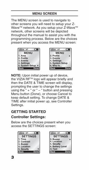
The MENU screen is used to navigate to other screens you will need to setup your Z-WaveTM network. As you setup your Z-WaveTM network, other screens will be depicted throughout the manual to assist you with the programming process. Below are the choices present when you access the MENU screen:
x1
Back
MENU1. Area2. Profile3. Events4. Settings5. System Setup
Done
x1
Back
MENU2. Profile3. Events4. Settings5. System Setup
Done6. Who Is...
NOTE: Upon initial power up of device, the VIZIA RFTM logo will appear briefly and then the DATE & TIME screen will display, prompting the user to change the settings using the " + " or " – " button and pressing Menu button (Done), or choose Cancel to keep default setting. To change DATE & TIME after initial power up, see Controller Settings.
GETTING STARTEDController Settings:Below are the choices present when you access the SETTINGS screen:
x1
Back
SETTINGS1. Time2. Contrast3. Buzzer4. Location5. Security
Done
x1
Back
SETTINGS
6. Battery Level
3. Buzzer4. Location5.
Security
DoneX. Test

DATE & TIME: Sets the date and time for your Programmer/Remote as follows:1. Press Menu.2. Select Settings.3. Select Time.4. Use the arrow buttons
to navigate and set the DATE & TIME using the " + " and " – " buttons.
5. Press the Menu button to save.CONTRAST: Sets the contrast for your Programmer/Remote LCD screen as follows:1. Press Menu.2. Select Settings.3. Scroll to and select
Contrast.4. Use the " + " and
" – " buttons to adjust the percentage of contrast.
5. Press the Menu button to save.BUZZER: Turns the buzzer on the Programmer/Remote keypad ON or OFF. When the buzzer is ON, a beep will be heard when pressing the keypad. When the buzzer is OFF, a click will be heard when pressing the keypad. The default setting is buzzer ON. Select as follows:1. Press Menu.2. Scroll to and select
Buzzer.3. Use the left and right
arrow buttons to turn buzzer ON or OFF.
4. Press the Menu button to save.
x1
Cancel
BUZZER
Save
Buzzer ON
x1
Cancel
DATE & TIME
Time: 09: 00 AM
Date: 06. 07. 2006
Wednesday
Done
x1
Cancel
CONTRAST
Save
050 %
4

Menu Navigation:
Main Screen
Functionality MenuStand By
Button Functionality
Left/RightSwitch Profile
+/-Dim/Brightlast area
On/OffOn/Off area
ProfileArea Events
new/edit
nameassociation
(delete)
new/edit/set
namebuttons 1...4
(delete)area
action(fade)
new/edit
nameenable/disable/(delete)
actionrecurrence
time
areaactionfade
recurrence
time/dawn/dusk
5

6
Settings System Settings
TimeNetwork
Include Node
Exclude Node
Update Cntrl
Remove Failed
Join Network
Dev properties
Association
buttons1...n
association
area association
(action)
Devices
set routes
set hail
Contrast
Buzzer
Location
Security
Battery Level
Test
date/time format
Replicate
enable events
Join
Dev Properties
Replicate
Primary Secondary
Utilities
Who Is...
Version
Dev Properties
Reset
Who Is...
Property
Property
NOTE:When in “Dev Properties” or when in the “Property”,it is possible to control a dimmer or a switch in thefollowing manner:Dimmer or Switch: 1 ON - turns ON, 1 OFF - turns OFFDimmer only: (+) - Bright, (-) - Dim

HOW TO USE THE RZCPG FEATURES
NOTE: If using a non-Leviton Programmer/Remote, refer to the Programmer/Remote instruction sheet for Including a device.Including/Excluding Devices:The first step in setting up your Vizia™ RF network is to INCLUDE each device using the Programmer/Remote. This step assigns each device a unique address assuring it can be controlled as a member of your home network and only by controllers that are members of your home network. Including a device to the Vizia™ RF network requires that you have the Programmer/Remote within proximity of the device being included (2-5 feet). This will ensure that each device is added correctly and eliminate possible errors and interference from other devices.Including a Dimmer, Switch or Plug-in into your Network:Using the Programmer/Remote, INCLUDE a Dimmer, Switch or Plug-in device as follows :1. Press Menu.2. Scroll to and select System Setup.3. Select Network.4. Select Include Node.
x1
Back
SYSTEM SETUP1. Network2. Association3. Devices4. Utilities
Done
x1
Back
NETWORK1. Include Node2. Exclude Node3. Update Cntrl4. Remove Failed5. Join Network
Done
7

5. Place the Controller, Dimmer, Switch or Plug-in into the INCLUSION mode. Refer to the individual device installation instructions for programming details.
6. While standing close to the device being included (approximately 2-5 ft.), press the center button on the Programmer/Remote to INCLUDE device in the network.
NOTE: Only one device may be included at any time.
7. Refer to the individual device installation instructions for programming details to continue inclusion process.
8. The Programmer/Remote will flash "Acquiring Mfg" and then assign a Home ID, Node ID, and Name for this device.
NOTE: This information will be stored in the Programmer/Remote to be used for future reference.
9. If necessary, you may name or edit the node of this device at this time. You can use the pre-made templates provided or label it with its own unique name.
Your Programmer/Remote is now ready to INCLUDE the device.
x1
Back
INCLUDE NODEPrepare deviceto be included
Start . [*]
Done
8

10. The device is now installed in the network.
NOTE: If a device has been successfully INCLUDED in the network and the user tries to include it again without first excluding it from the network, the device will retain the first node ID it had received and ignore the second.
You may now move to the next device to include. If you are finished including devices, select the BACK button several times until you have exited the INCLUDE screen.
x1
TEXT EDITORDimmer #3LevitonMaster Bedroom
Template
x1
TEXT EDITORDimmer #3LevitonMaster Bedroom
Abc
To use the pre-made templates, use the arrow buttons to select name.
To create a unique name, press the Menu button to toggle to text mode and use arrow keys to create name.
Your remote screen will display: Node included Node # x Node name: xxx
9
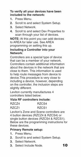
To verify all your devices have been included to the network:1. Press Menu.2. Scroll to and select System Setup.3. Select Network.4. Scroll to and select Dev Properties to
scan through your list of devices.NOTE: At this point you can add devices to AREA for later use. See AREA programming on setting this up.Including a Controller into your Network:Controllers are a special type of device that can be a member of your network. Controllers contain additional information about the devices in the network that are close to them. This information is used to help route messages from device to device.This procedure is very close to including a device, however, depending on the controller, the inclusion steps are slightly different.Leviton currently manufactures 4 controllers listed below: Vizia RF controllers include:RZCZ4 RZCS4RZCZ1 RZCS1Leviton’s Zone and Scene controllers are 4 button devices (RZCZ4 & RZCS4) or single button devices (RZCS4 & RZCS1). Below are the programming instructions for these devices.Primary Remote setup:1. Press Menu.2. Scroll to and select System Setup.3. Select Network.3. Select Include Node. 10

NOTE: If you are unable to include your device before trying again you must first exclude the device, then try the INCLUSION procedure again.Excluding a Dimmer, Switch or Plug-in from your Network:Using the Programmer/Remote, INCLUDE a Dimmer, Switch or Plug-in device as follows :1. Press Menu.2. Scroll to and select System Setup.3. Select Network.4. Select Exclude Node.Refer to the individual device installation instructions for excluding a device.
11
For RZCS4 and RZCZ4 Controllers:
Refer to the individual device installation instructions for programming details.
For RZCS1 and RZCZ1 Controllers:
Refer to the individual device installation instructions for programming details.
Now your primary remote is ready to include your controller.
12
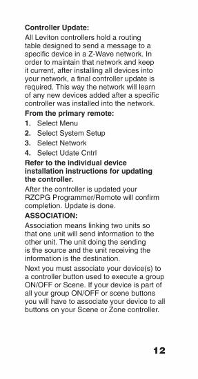
Controller Update:All Leviton controllers hold a routing table designed to send a message to a specific device in a Z-Wave network. In order to maintain that network and keep it current, after installing all devices into your network, a final controller update is required. This way the network will learn of any new devices added after a specific controller was installed into the network.From the primary remote:1. Select Menu2. Select System Setup3. Select Network4. Select Udate CntrlRefer to the individual device installation instructions for updating the controller.After the controller is updated your RZCPG Programmer/Remote will confirm completion. Update is done.ASSOCIATION:Association means linking two units so that one unit will send information to the other unit. The unit doing the sending is the source and the unit receiving the information is the destination.Next you must associate your device(s) to a controller button used to execute a group ON/OFF or Scene. If your device is part of all your group ON/OFF or scene buttons you will have to associate your device to all buttons on your Scene or Zone controller.

13
To Associate:1. Select Menu.2. Select System Setup. 3. Scroll to and select Association.4. Select Controller from list.5. Select Button 1 - 4.6. Select device(s) by pressing the " + "
button to add or " – " button to subtract an association.
Repeat this step for each button on your scene or zone controller by associating each device you would like on that scene by adding it to your selected button.
NOTE: It is important that association be created after all devices involved are installed in the network. AREA:An Area is a grouping of devices or zones in a network designed to easily associate multiple devices to a scene or group ON/OFF button on a controller. It also allows for easily assigning a group of devices to a button on a scene or Group ON/OFF Zone controller.1. Select Menu.2. Select AREA3. Select <<new>>4. Select Name: Area #_Here you can either assign a name from a list of templates or assign a unique name to your area by choosing the ABC feature.NOTE: The Menu button will toggle from Template to Abc to ABC to Abc to 123 and back to Template again. This feature

14
allows you to access the Template names and to select capital/undercase letters and numerals to name your Area. To use the pre-made templates, with Template chosen, use the up and down arrow buttons to select name.To create a unique name, under ABC (or abc, 123) use the up and down arrow buttons to change each letter and the side arrow buttons to navigate.Next you will associate the devices of your choice to your newly created area.1. Select Association2. Select device by pressing the " + "
button to add or " – " button to subtract an association.
3. Select Save after each area you create.
Once all your areas have been created select Done and you will return to the main Menu.EDIT:1. Select Menu.2. Select Area.3. Scroll to Area to edit and select.A list of options will display allowing you to edit your AREA.DELETE:1. Select Menu.2. Select Area.3. Scroll to Area to delete and select.4. Select Delete Area.5. Press Menu button (Yes) to delete.Your Area will be removed from the list.

15
PROFILE:A Profile is a function within each Leviton controller to allow control of Area’s, Groups, Zones or Scenes from the 4 buttons on your handheld Programmer/Remote. You are able to create multiple profiles in your handheld remote. Each profile will control a different area, group, zone or scene in your system. Simply assign a profile to a button by doing the following.1. Select Menu.2. Scroll and select Profile.3. Select <<new>>.4. Select Name: Profile #_5. Select ButtonsSelect a button (1 - 4) to assign your profile to. You will be able to assign it to one of 4 buttons on your remote. Now you can create a new profile and assign a new group of devices to a new set of buttons assigned to your newly created profile.EDIT:1. Select Menu.2. Scroll and select Profile.3. Scroll to Profile to edit and select.A list of options will display allowing you to edit your Profile.DELETE:1. Select Menu.2. Select Profile.3. Scroll to Profile to delete and select.4. Select Delete Profile.5. Press Menu button (Yes) to delete.Your Profile will be removed from the list.

16
TIMED EVENTSTimed Events allows for the programming of up to 64 timed events. Each one of the timed events can be programmed to set a device/scene to an ON time. A recurrence can also be specified. The recurrence selects what days of the week or month the time clock will run on. The ON times can specify a particular time of the day, or a value relative to the calculated sunrise or sunset times dusk or dawn. A time randomizer provides for some daily variations so that it does not appear to an outsider that the lights are controlled by a mechanical system. The default programmed state of the timers is that they are DISABLED. Completion of the Wizard will enable preferred events to be activated.To set a timed event select your events option and follow the steps below: 1. Select Menu.2. Select Events.3. Select <<new>>4. Select Event #_ to name your Event5. Scroll to option 2 and use side arrow
buttons until Enabled is displayed.6. Scroll to and select Action.7. Select the area number you want to
enable.8. Scroll to option 2 and use side arrow
buttons to select ON/OFF, Max, or a Scene (from 1-255)
9. Scroll to option 3 and use the side arrow buttons to set the fade rate for the selected action.
10. Press Menu (Save).11. Scroll to Recurrence and select.12. Use side arrow buttons to scroll
through the options Daily, Weekdays, Weekends, One Time, Monthly, Weekly, and Daily.
13. Use up and down arrow keys to navigate and " + " and " – " keys to change months and days incrementally.
14. Press Menu button (Save).15. Scroll to and select option 5
(Time Setting). 16. Use side arrow buttons to scroll and
select Time of Day, Dusk or Dawn. Use up and down arrows to navigate and " + " and " – " buttons to change Time settings.
17. Press Menu button (Save).EDIT:1. Select Menu.2. Scroll to and select Events.3. Scroll to Event to edit and select.A list of options will display allowing you to edit your EVENT.DELETE:1. Select Menu.2. Select Events.3. Scroll to option 2 and use either side
arrow button until Delete is displayed.5. Press Menu button (Save).5. Press Menu button (Yes).Your Event will be removed from the list.
17

18
SETTING A SCENE:Press and hold scene button 1 on the scene controller until the LED blinks green. Next locate each dimmer/switch/plug-in that you have associated with scene one (button 1) [Note: this could be individual devices or a pre-configured Area] and set each device to a desired light level. Finally press scene 1 (button 1) again to store your scene for that button. Repeat this process for each button on the scene controller.REMOVING A FAILED DEVICE:If a device fails in a z-wave network it will list itself under the REMOVE FAILED option in your RZCPG remote. Any devices listed here have failed and will need to be removed from the list. NOTE: You will also want to set the device back to factory default condition see device instruction sheet do factory default a device.REPLACING A FAILED DEVICE:STILL NEED TO ADDWHO IS.... Feature:The WHO IS feature gives you the ability to identify a device by activating the WHO IS utility on the RCZPG remote and pressing the button on the device.After the information is received by the RZCPG remote it will display the device ID and the NAME assigned to the device you activated. This is especially helpful for devices that have the same name or a device that was assigned the wrong ID during installation.
19
RZCPG REMOTE VERSION Displays the version of software used on the RZCPG remote controller and displays the version of Z-Wave firmware the RZCPG is using. It also displays the HID (Home ID) NID (Node ID) and the Serial Number for this device. JOIN NETWORKBefore you can replicate primary Programmer/Remote information to your secondary remotes you must INCLUDE your secondary remotes in the primary remotes network. Join Network option will allow you to Include a secondary remote to your network. You can join as many secondary remotes as you like.NOTE: The RZCPG primary Programmer/Remote will not transfer INCLUDE/EXCLUDE ability to the secondary remotes. This capability remains with the primary Programmer/Remote only.Primary Remote:1. Select Menu.2. Scroll to and select System Setup.3. Select Network.4. Select Include Node. Secondary remote: using the RZCPG1. Select Menu.2. Scroll to and select System Setup.3. Select Network.4. Select Join NetworkYour secondary remote has to be put into JOIN NETWORK mode for it to be included to a network. Refer to the remote manufacturer instructions on setting this up if a non Leviton remote is used.

20
REPLICATION:Replication allows you to assign control responsibility to other remotes (secondary remotes). Replication option will allow you to send primary controller information to a secondary remote. A replication of the Primary controller is done as follows:Primary Remote:1. Select Menu.2. Scroll to and select System Setup.3. Select Network.4. Select Replication. 5. Scroll to and select Send Data.Secondary Remote (Leviton RZCPG)1. Select Menu.2. Scroll to and select System Setup.3. Select Network.4. Select Replication. 5. Select Get Data.Once replication has been completed to your secondary remote it will show an X2 in the upper middle of your screen, indicating that it is a secondary controller. Your secondary controller’s home ID will also change to the home ID of your primary controller. If replication should fail, ensure that your secondary controller has been included into the primary controller’s network and restart steps above.DEVICE CONTROL LISTUnder the UTILITES tab scroll down to DEVICES, press ENTER. A list of all device installed in your network will appear. Scrolling over any one device will

allow you to turn ON or OFF that device using button 1 ON/OFF on your RZCPG remote. If it is a dimmer you can use the " + " and " – " buttons to dim and brighten the load.RESET PROGRAMMER/REMOTE Resets your RZCPG Programmer/Remotes back to factory default and erases any programmed information from the remote. NOTE: Resetting the RZCPG Programmer/Remote to factory default does not reset your devices. If you want to factory reset your devices refer to the individual device instruction sheet for that device.OPERATION MODESecondary Wireless Programmer/Remote Indication:After you have replicated your secondary Programmer/Remote to your network, the LCD display will indicate it is secondary by displaying an X2 in the top center of the screen.LOW BATTERY INDICATIONSelecting and Controlling Profiles from the Programmer/Remote:Once you have created a profile you will be able to control it from any of your primary or secondary remotes in your network. To select the profile to control PRESS the LEFT or RIGHT arrows on the controller the bottom of your remote will display the profiles you have created and indicate which profile you are currently able to control. To control that profile use the 1-4 ON/OFF buttons on the remote. You
21
will be able to toggle on and off that area assigned to that button. If a dimmer is in the profile tapping the PLUS + or MINUS – buttons will dim and bright the load.


