marine engineering systems design department - … details for small bore socket weld flanges ......
TRANSCRIPT
Marine Institute of Memorial University of Newfoundland
Pipe Standards
Marine Engineering Systems Design Department
Revision 0

Page 1 of 135
Pipe Design Standards Marine Engineering Systems Design Department
List of Revisions
Revision Description Date 0 INITIAL ISSUE Feb/24/2010
Page 2 of 135
Pipe Design Standards Marine Engineering Systems Design Department
Abstract
The standards described in this document are primarily intended for Marine Engineering Systems Design students enrolled in the three year Diploma of Technology program. Introducing design standards to the classroom at the Marine Institute serves two purposes. First, it makes students aware such standards exist and familiarises them with the format and use of such standards as found in the shipbuilding industry. Secondly, design standards will allow a class of students to work to the same standard and therefore produce similar quality drawings as would be expected by industry drawing offices. This standard can be used as a constant source of reference by all students. It should be noted that most engineering and design offices employ their own standards to which all engineers and designers must adhere. The primary purpose of the standard is to allow the designer to reference a particular standard detail on a working drawing and thereby not have to draw this detail. In the classroom at the Marine Institute, this is not the case; standards used by the student are expected to be drawn and fully detailed. Instructors may deviate from this standard depending on the type of lab/drawing work being done.
Page 3 of 135
Pipe Design Standards Marine Engineering Systems Design Department
Index
List of Revisions ....................................................................................................................1
Abstract ...................................................................................................................................2
Index.........................................................................................................................................3
General Notes:........................................................................................................................8
Flanges ....................................................................................................................................9
Flange Bolt Hole Orientation.............................................................................................................10
Flange Installation Orientation..........................................................................................................11
Welding Details for Small Bore Socket Weld Flanges .........................................................................12
Welding Details for Large Bore Socket Weld Flanges .........................................................................13
Fabrication and Installation Details for 150# Bulkhead Flanges .........................................................14
Orifice Plates for 300# Raised Face Flanges .......................................................................................15
Orifice Plates for 300# Raised Face Flanges .......................................................................................16
Pipe Run for Orifice Plate Installations ..............................................................................................17
Orifice Plate & Tap Installation Details ..............................................................................................18
Sliding Spectacle 150# Blind Detail ....................................................................................................19
Sliding Spectacle Blind Dimensions ...................................................................................................20
Sliding Spectacle 150# Blind Bolting Detail ........................................................................................21
150# Flange Bolting Isolation Sleeve .................................................................................................22
Pipe and Fitting Details.......................................................................................................23
Slip‐On Welding Sleeve Detail ...........................................................................................................24
Slip‐On Welding Sleeve Notes ...........................................................................................................25
3D Pipe Bending Requirements .........................................................................................................26
Pipe Extrusion Details .......................................................................................................................27
Pipe Extrusion Details .......................................................................................................................28
Installation Details for Sock‐O‐Lets....................................................................................................29
Installation Details for Thread‐O‐Lets................................................................................................30
Installation Details for Weld‐O‐Lets ..................................................................................................31
Installation Details for Branch Connections.......................................................................................32
Vent and Drain Installation Details....................................................................................................33
Pressure Indicator Installation Details ...............................................................................................34

Page 4 of 135
Pipe Design Standards Marine Engineering Systems Design Department
Pressure Indicator Board Detail.........................................................................................................35
Pressure Indicator Board Detail.........................................................................................................36
Pressure Indicator Board Detail.........................................................................................................37
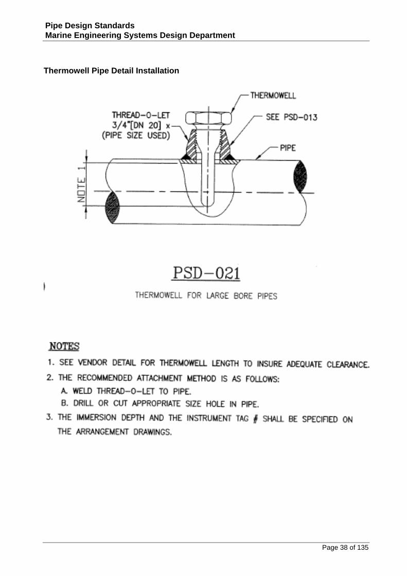
Thermowell Pipe Detail Installation ..................................................................................................38
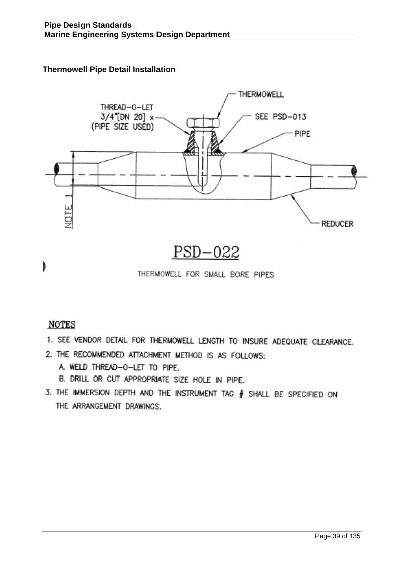
Thermowell Pipe Detail Installation ..................................................................................................39
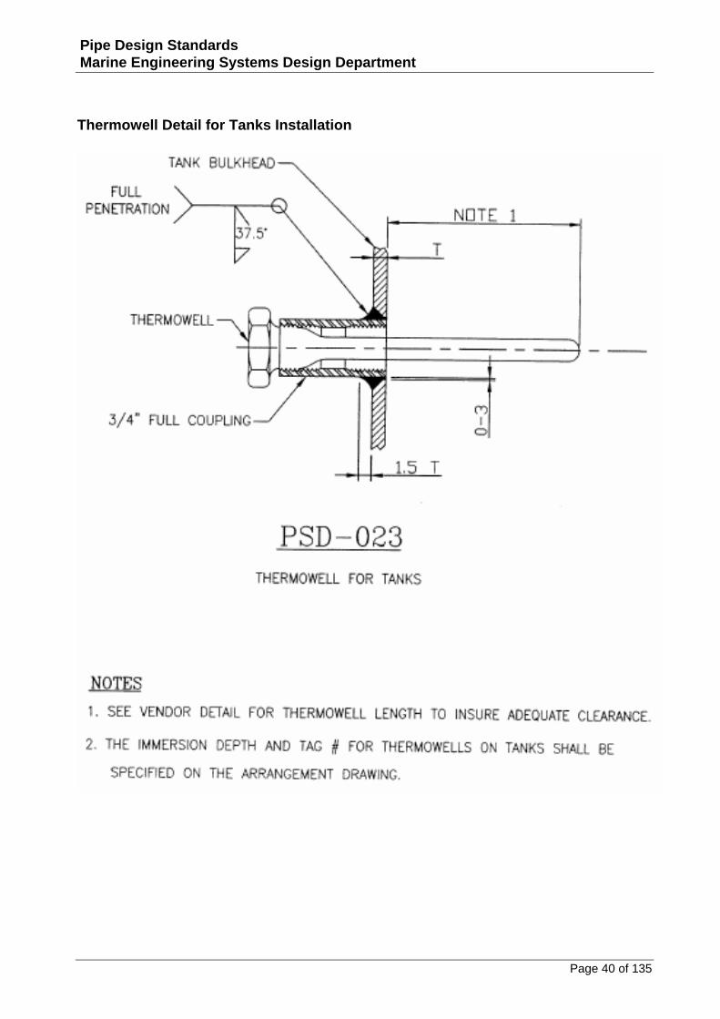
Thermowell Detail for Tanks Installation...........................................................................................40
Pressure Vessels .................................................................................................................41
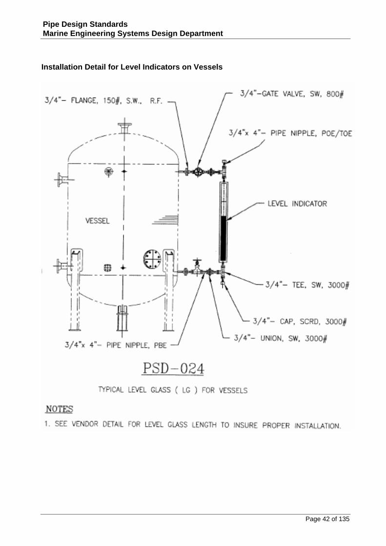
Installation Detail for Level Indicators on Vessels..............................................................................42
Installation Detail for Bridle Assembly on Vessels .............................................................................43
Installation Detail for Pressure Safety Valve on Vessels.....................................................................44
Special Connections ...........................................................................................................45
Dresser Coupling Assembly Detail .....................................................................................................46
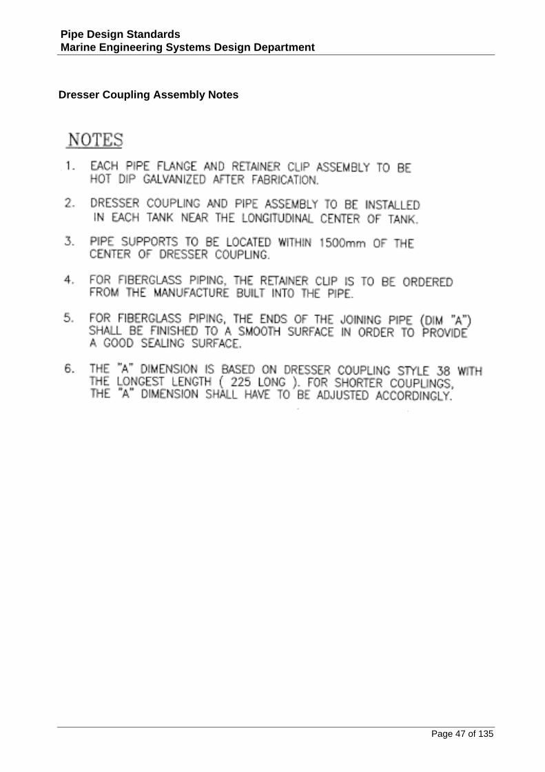
Dresser Coupling Assembly Notes .....................................................................................................47
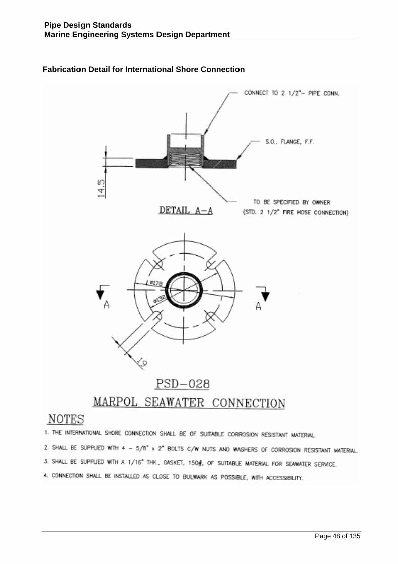
Fabrication Detail for International Shore Connection.......................................................................48
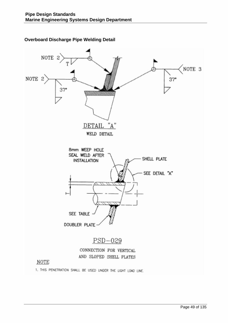
Overboard Discharge Pipe Welding Detail .........................................................................................49
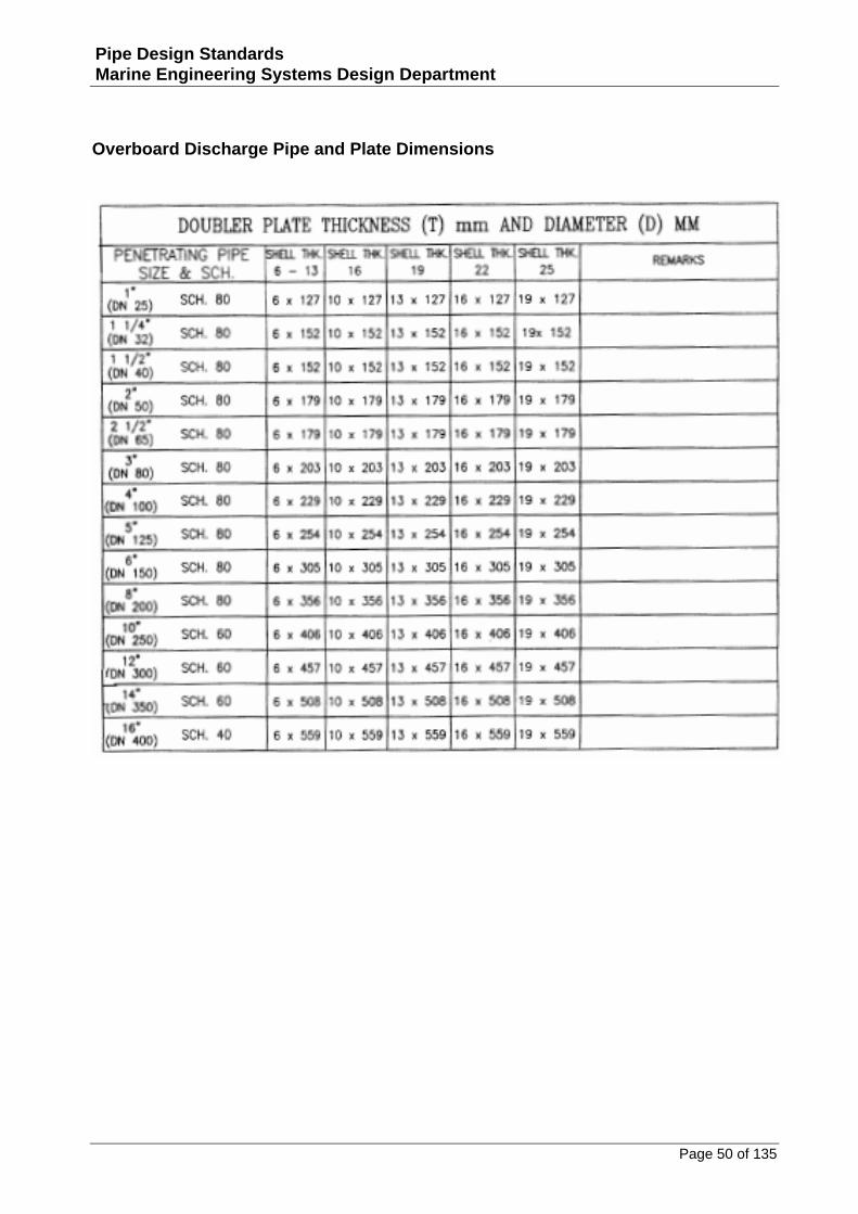
Overboard Discharge Pipe and Plate Dimensions ..............................................................................50
Overboard Discharge Pipe Notes.......................................................................................................51
Overboard Discharge Pipe Welding Details .......................................................................................52
Overboard Discharge Pipe and Plate Dimensions ..............................................................................53
Overboard Discharge Pipe and Valve Detail ......................................................................................54
Sea Chest Nozzle Installation Detail ..................................................................................................55
Sea Chest Nozzle Installation Dimensions..........................................................................................56
Sea Chest Flange 150# Installation Detail ..........................................................................................57
Bulkhead Penetrations........................................................................................................58
Bulkhead and Deck Penetration – Single Sided Pad (ANSI) ................................................................59
Bulkhead and Deck Penetration – Single Sided Pad (DIN) ..................................................................60
Single Sided Pad for Inside Tank Piping .............................................................................................61
Bulkhead and Deck Penetration – Double Sided Pad .........................................................................62
Standard Bulkhead and Deck Pipe Penetration .................................................................................63
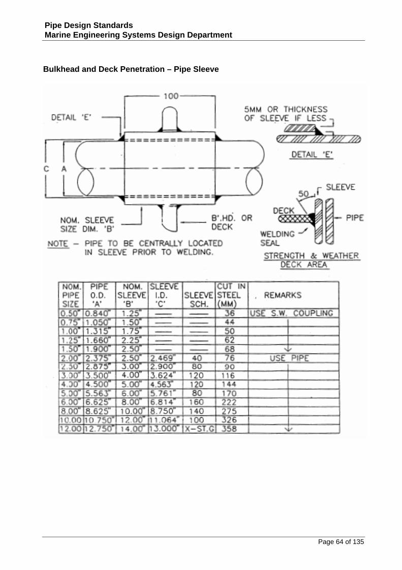
Bulkhead and Deck Penetration – Pipe Sleeve...................................................................................64
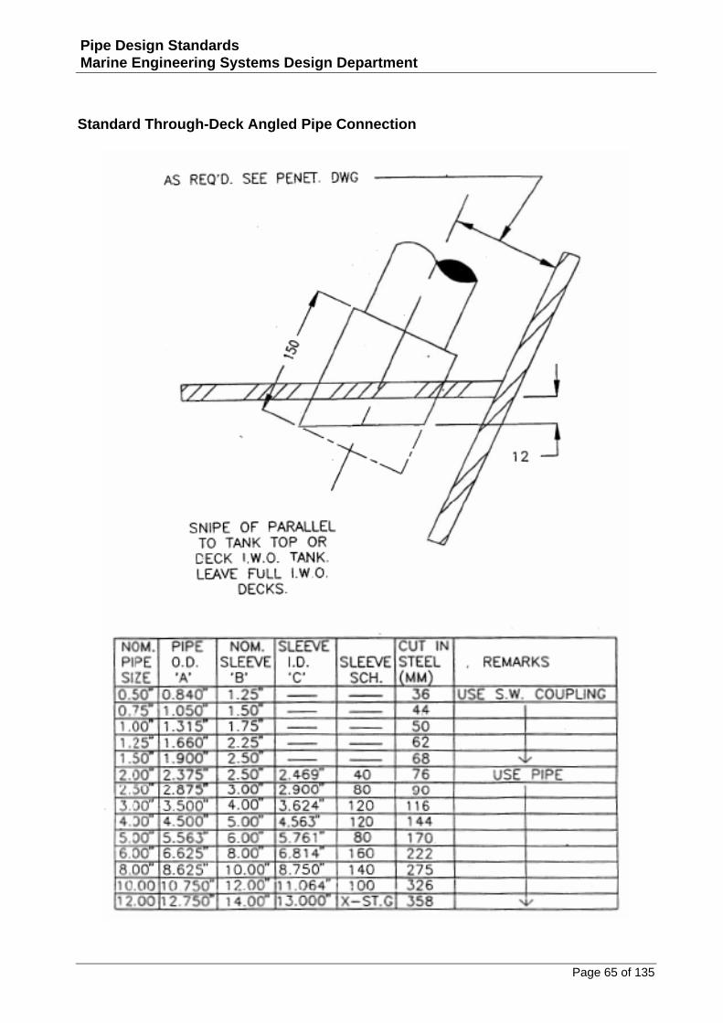
Standard Through‐Deck Angled Pipe Connection ..............................................................................65
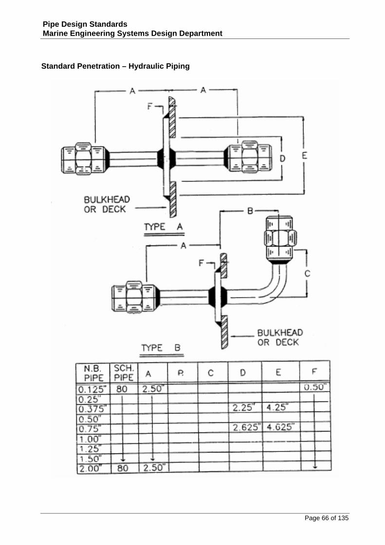
Standard Penetration – Hydraulic Piping...........................................................................................66
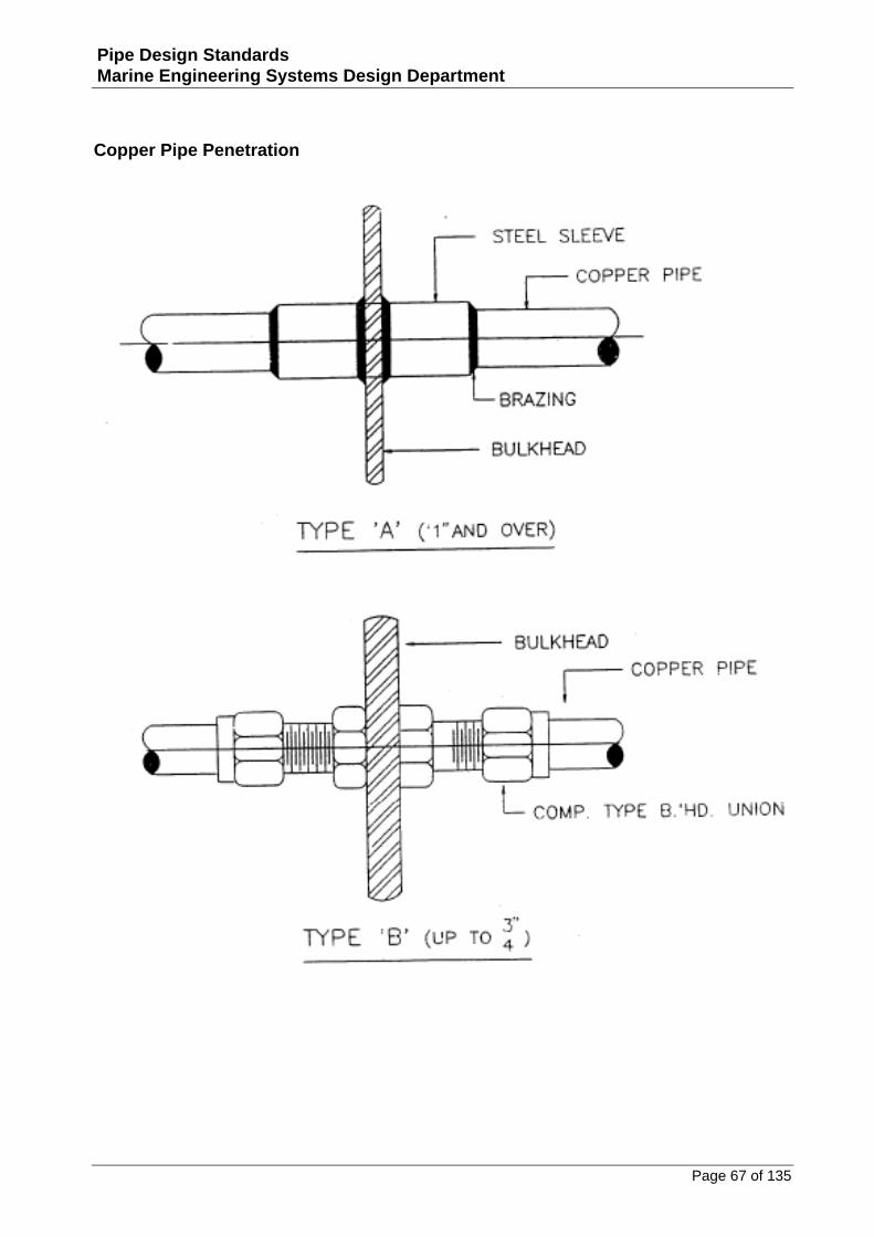
Copper Pipe Penetration...................................................................................................................67
Page 5 of 135
Pipe Design Standards Marine Engineering Systems Design Department
Plastic Pipe Penetrations...................................................................................................................68
Penetration – Main Sea Inlet on Sea Box...........................................................................................69
Sounding Pipe – Complete with Parallel Plug Cock ............................................................................70
Deck Plate (Welded Type) .................................................................................................................71
Duct Penetrations .............................................................................................................................72
Spectacle Flange ...............................................................................................................................73
Strum Box for Bilge Suction...............................................................................................................74
Sea Chest / Sea Bay Connection ........................................................................................................75
Tank Connection ‐ Flanged ................................................................................................................76
Deck Drain (Exterior).........................................................................................................................77
Fabrication and Installation Details for 150# Deck and Bulkhead Penetrations..................................78
Fabrication and Installation Details for 150# Deck and Bulkhead Penetrations..................................79
Fabrication and Installation Details for Double150# Penetrations .....................................................80
Fabrication and Installation Details for 3‐Way 150# Penetrations .....................................................81
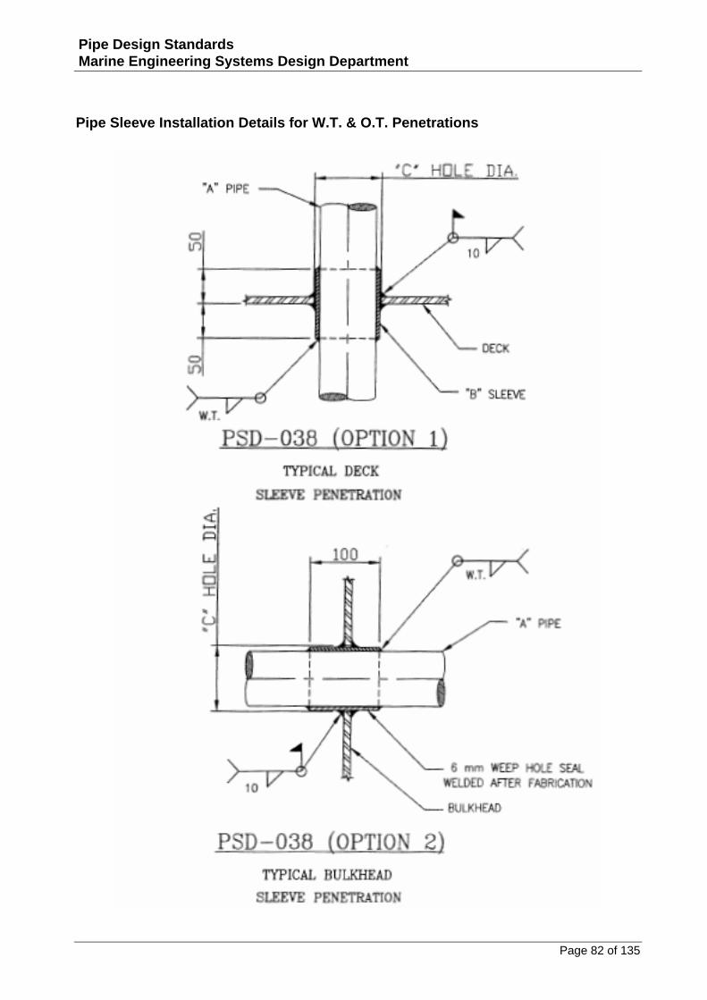
Pipe Sleeve Installation Details for W.T. & O.T. Penetrations ............................................................82
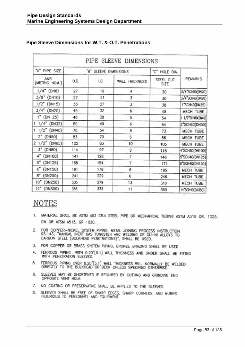
Pipe Sleeve Dimensions for W.T. & O.T. Penetrations .......................................................................83
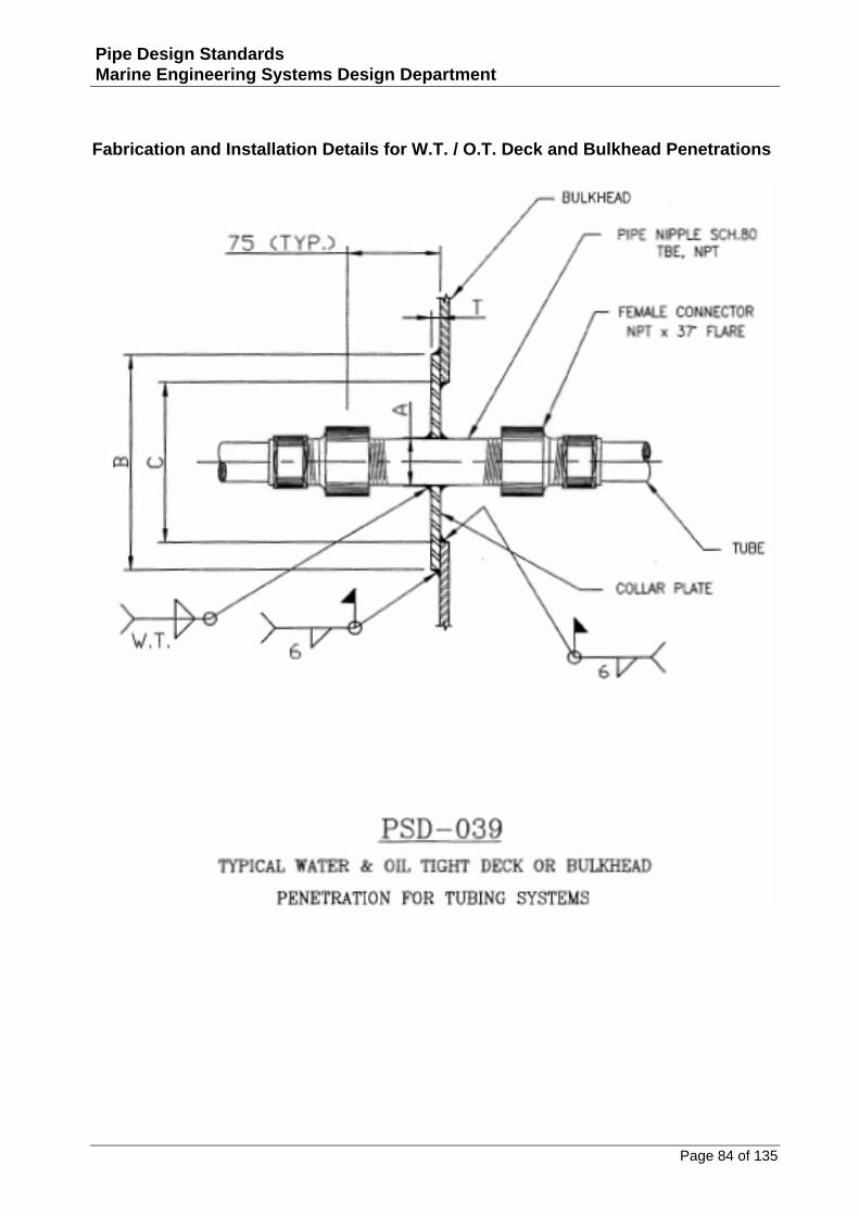
Fabrication and Installation Details for W.T. / O.T. Deck and Bulkhead Penetrations ........................84
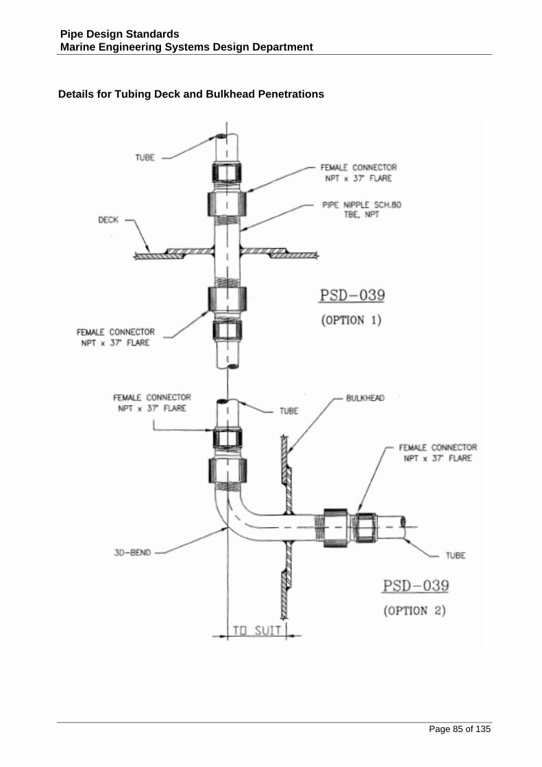
Details for Tubing Deck and Bulkhead Penetrations ..........................................................................85
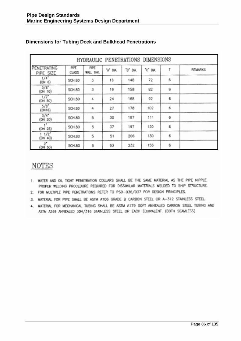
Dimensions for Tubing Deck and Bulkhead Penetrations...................................................................86
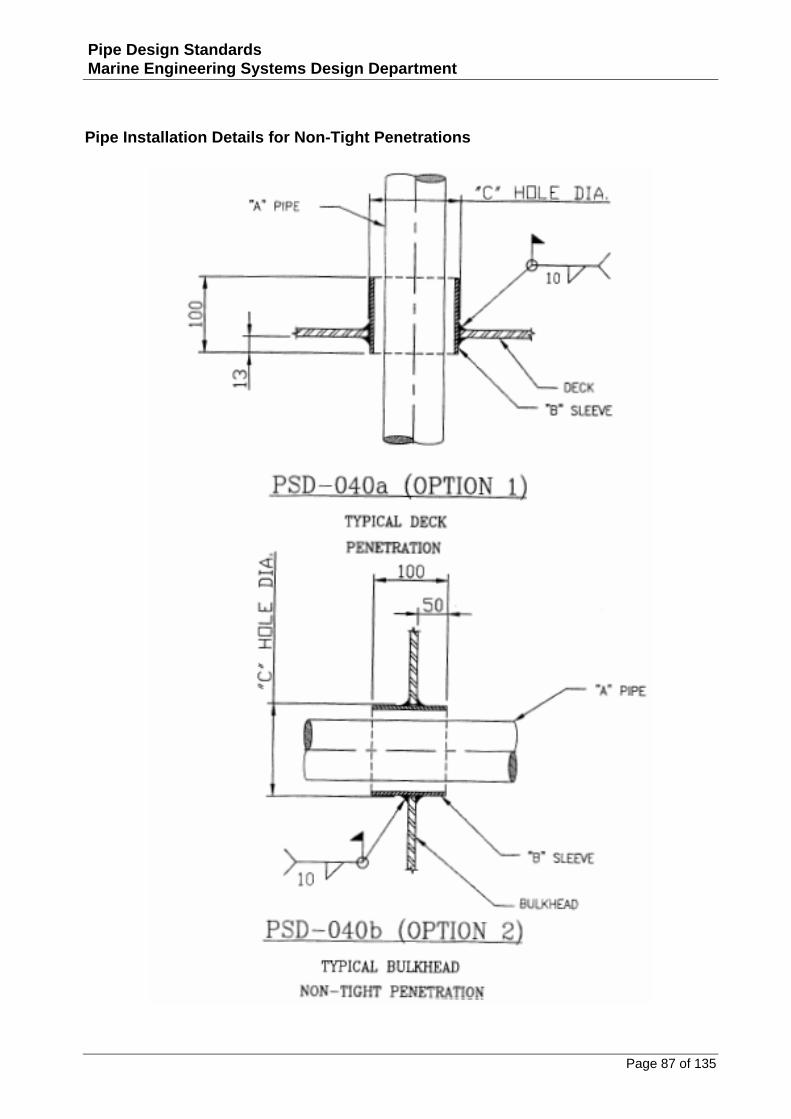
Pipe Installation Details for Non‐Tight Penetrations..........................................................................87
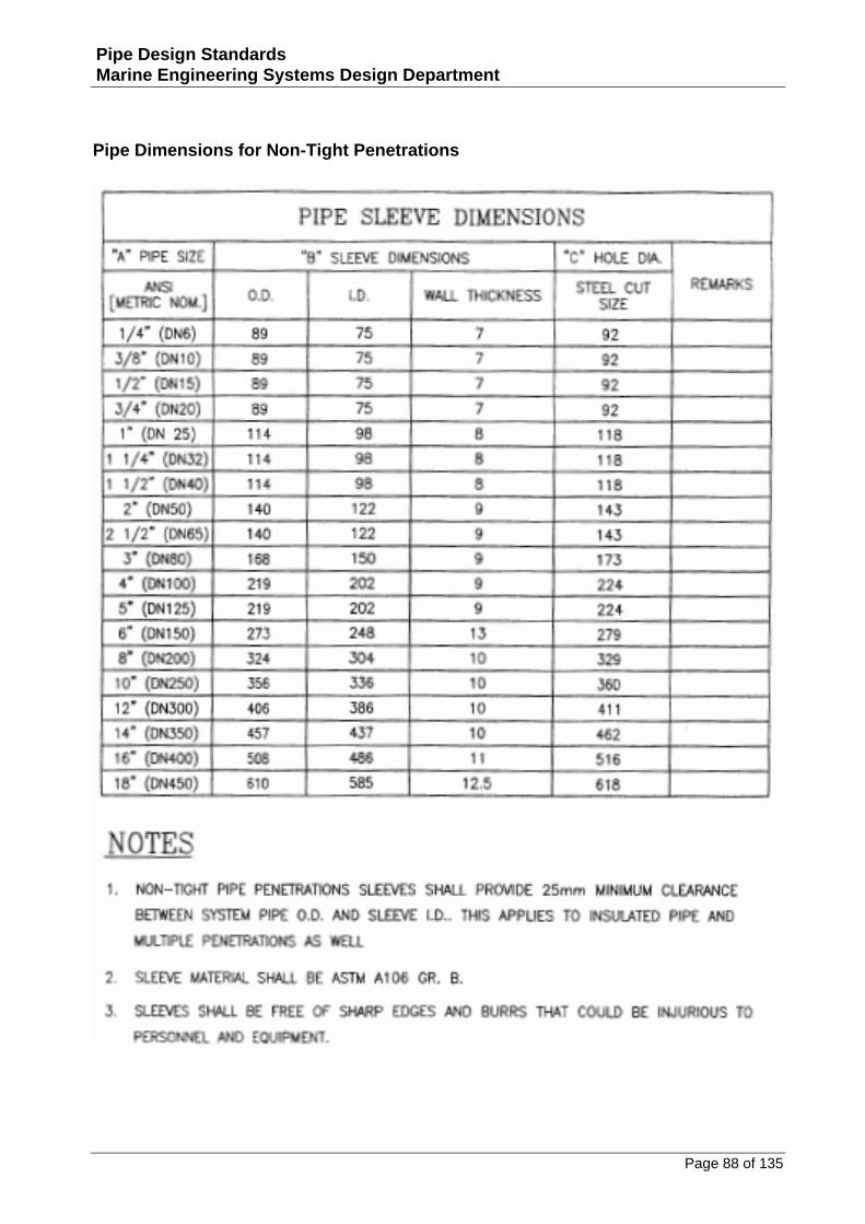
Pipe Dimensions for Non‐Tight Penetrations.....................................................................................88
Drain Details .........................................................................................................................89
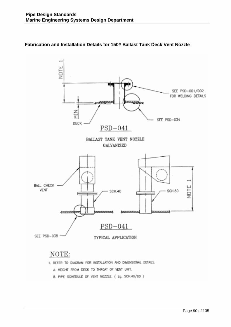
Fabrication and Installation Details for 150# Ballast Tank Deck Vent Nozzle......................................90
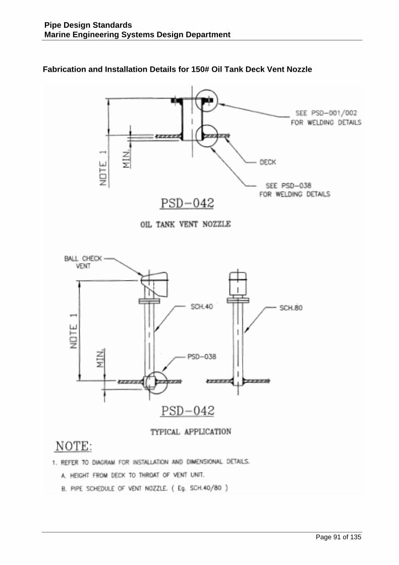
Fabrication and Installation Details for 150# Oil Tank Deck Vent Nozzle............................................91
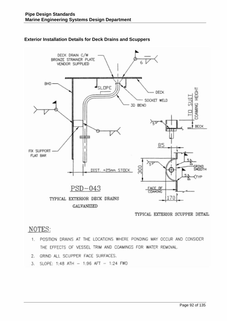
Exterior Installation Details for Deck Drains and Scuppers.................................................................92
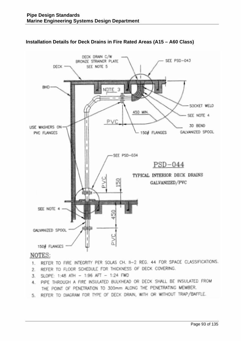
Installation Details for Deck Drains in Fire Rated Areas (A15 – A60 Class)..........................................93
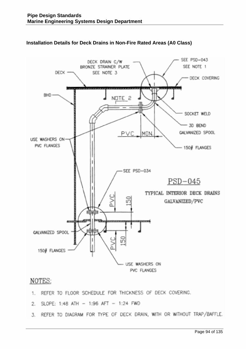
Installation Details for Deck Drains in Non‐Fire Rated Areas (A0 Class)..............................................94
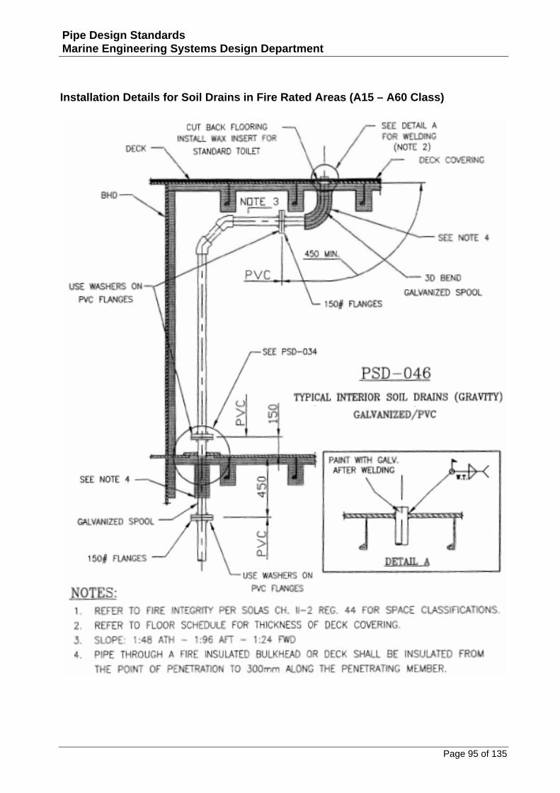
Installation Details for Soil Drains in Fire Rated Areas (A15 – A60 Class)............................................95
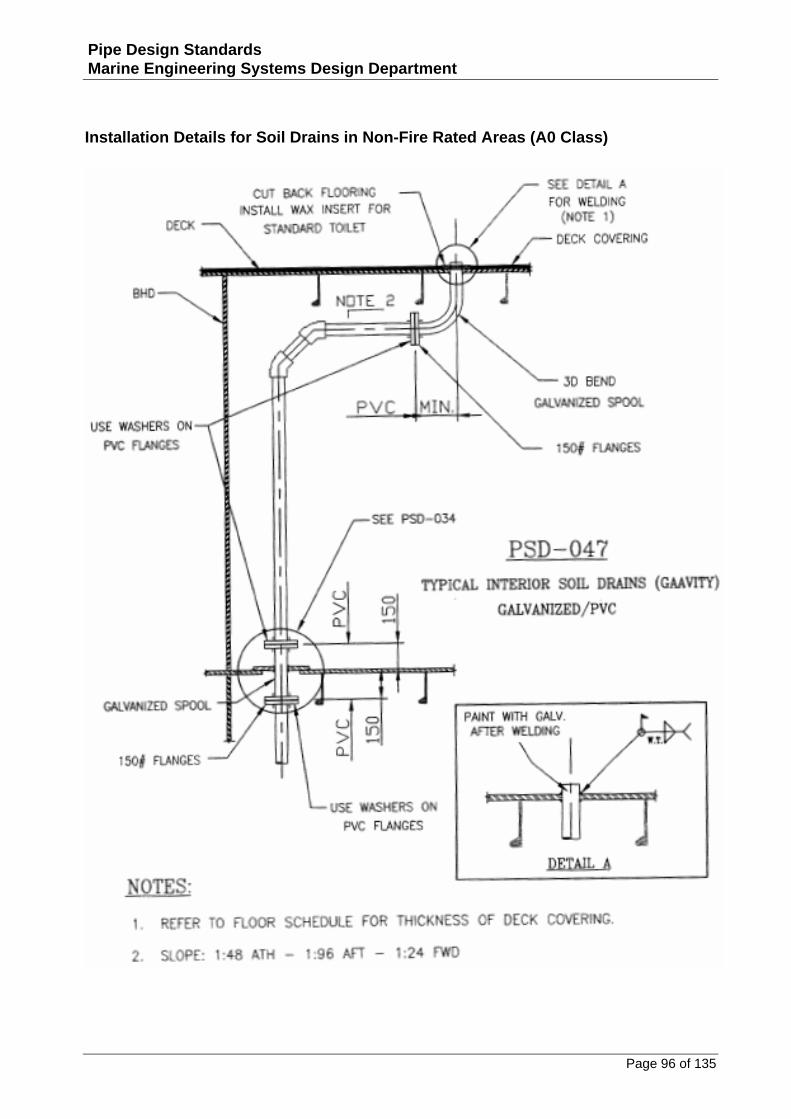
Installation Details for Soil Drains in Non‐Fire Rated Areas (A0 Class)................................................96
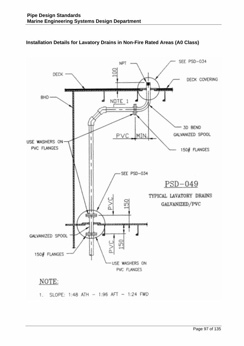
Installation Details for Lavatory Drains in Non‐Fire Rated Areas (A0 Class)........................................97
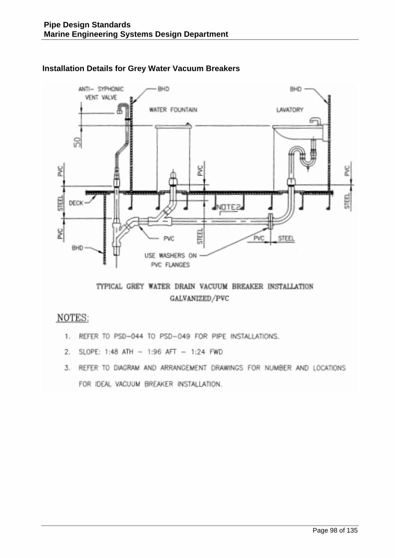
Installation Details for Grey Water Vacuum Breakers........................................................................98
Installation Details for Soil Drain Vacuum Breakers...........................................................................99
Installation Details for Lavatory in Fire Rated Areas (Class A15‐A60) ...............................................100
Page 6 of 135
Pipe Design Standards Marine Engineering Systems Design Department
Installation Details for Lavatory in Non‐Fire Rated Areas (A0 Class).................................................101
Installation Details for Water Closet in‐Fire Rated Areas (Class A15‐A60) ........................................102
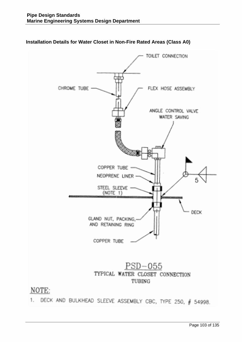
Installation Details for Water Closet in Non‐Fire Rated Areas (Class A0) ..........................................103
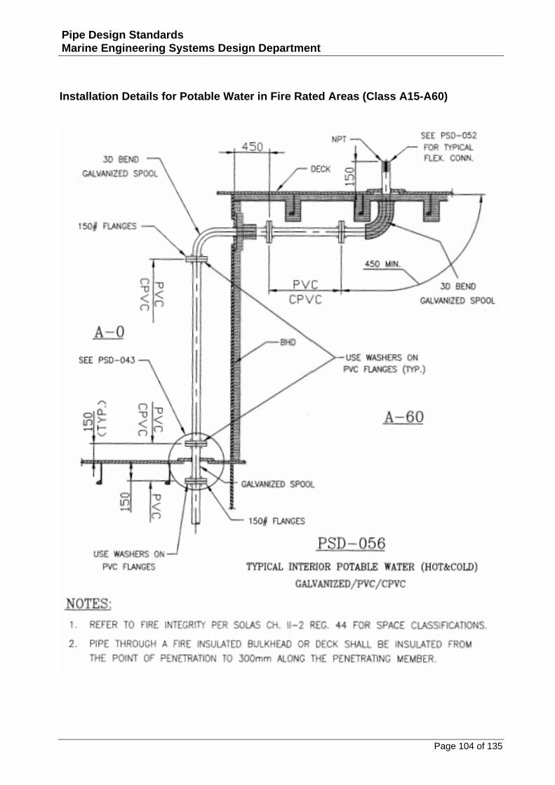
Installation Details for Potable Water in Fire Rated Areas (Class A15‐A60) ......................................104
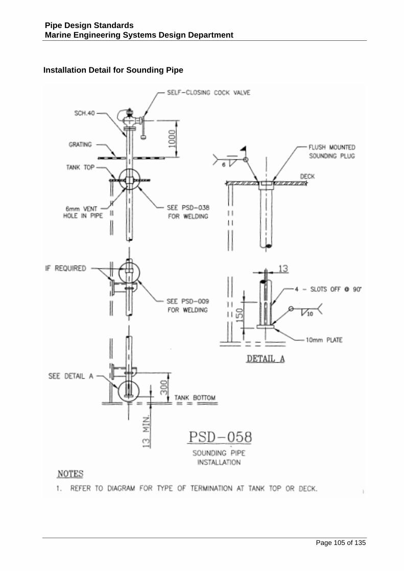
Installation Detail for Sounding Pipe ...............................................................................................105
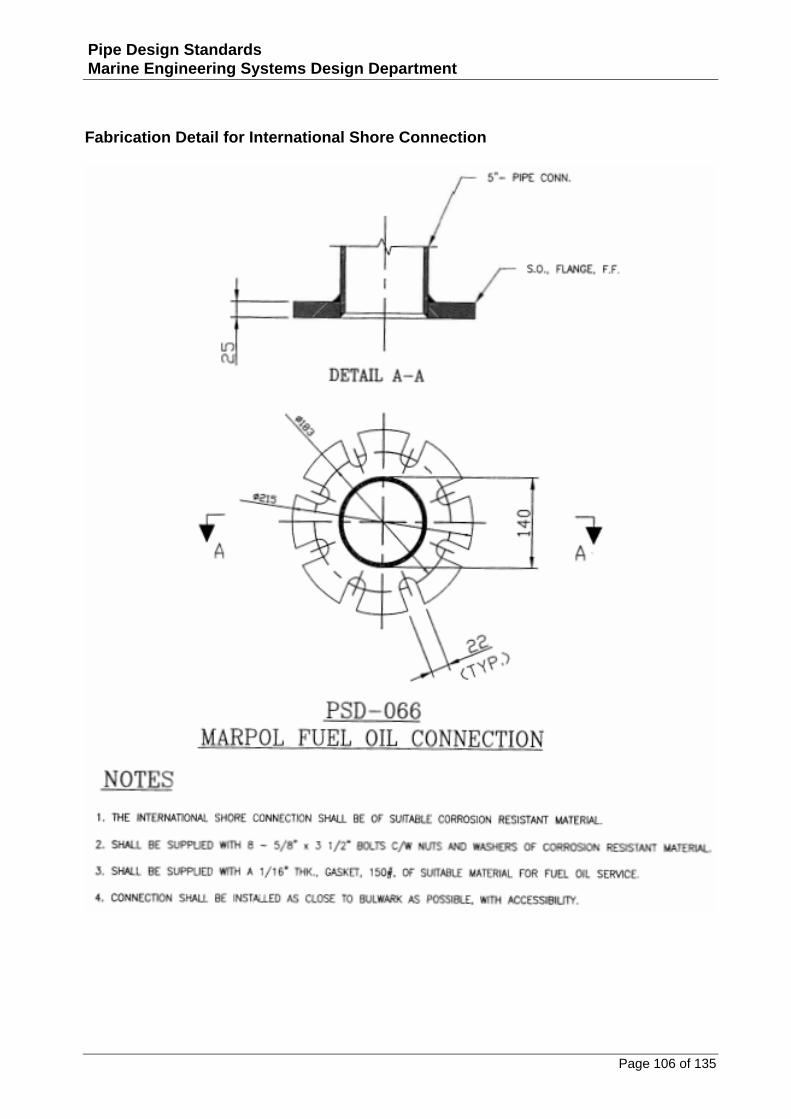
Fabrication Detail for International Shore Connection.....................................................................106
Pipe Supports ..................................................................................................................... 107
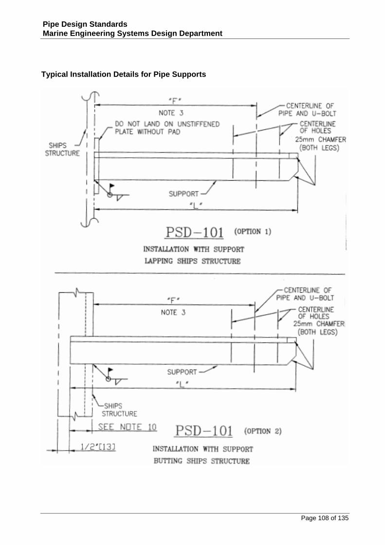
Typical Installation Details for Pipe Supports ..................................................................................108
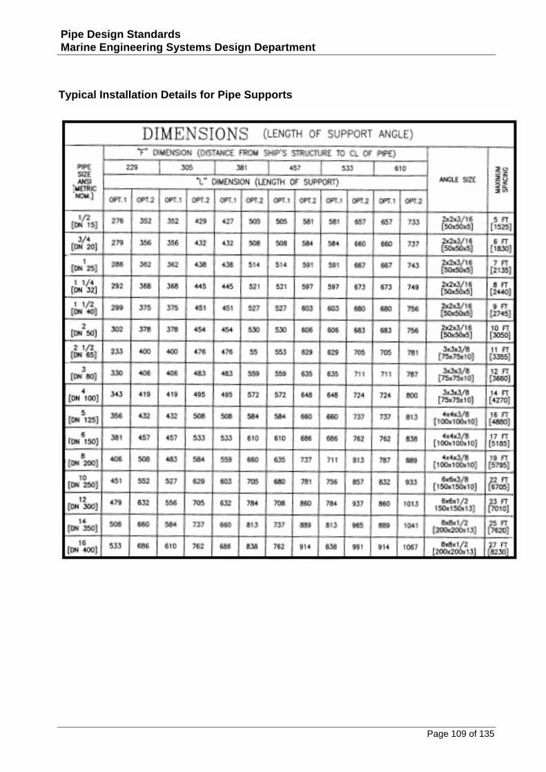
Typical Installation Details for Pipe Supports ..................................................................................109
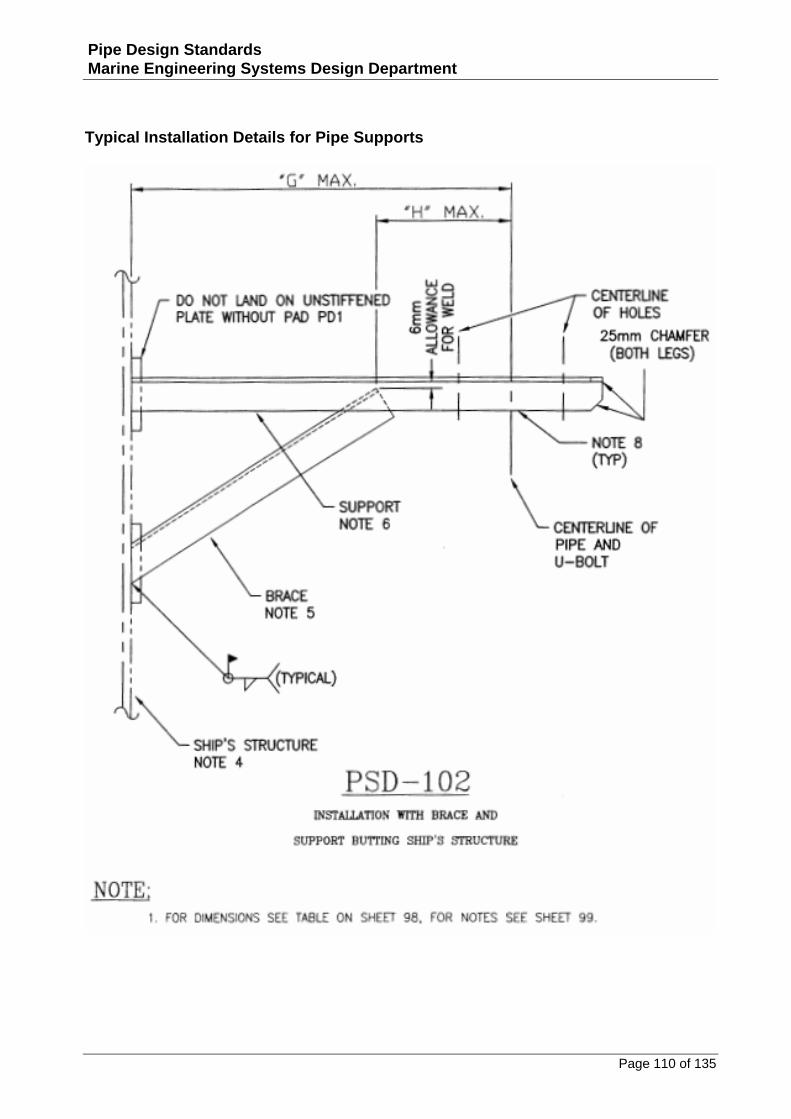
Typical Installation Details for Pipe Supports ..................................................................................110
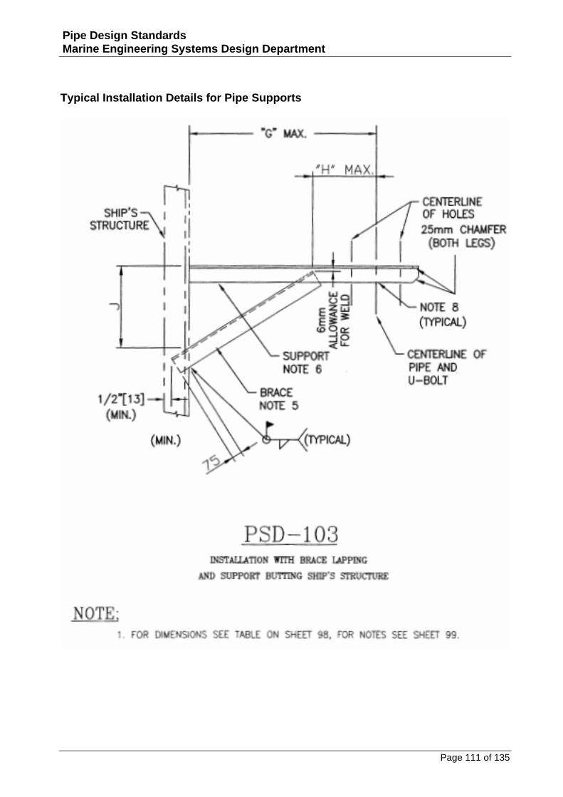
Typical Installation Details for Pipe Supports ..................................................................................111
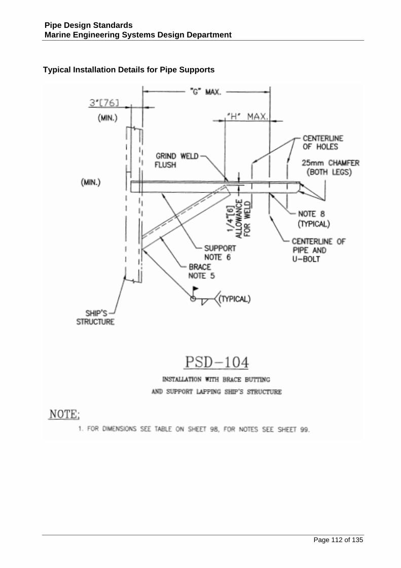
Typical Installation Details for Pipe Supports ..................................................................................112
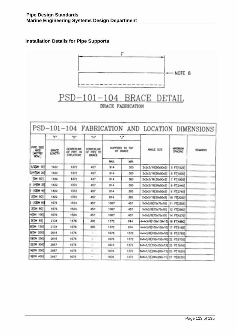
Installation Details for Pipe Supports ..............................................................................................113
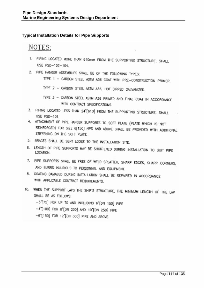
Typical Installation Details for Pipe Supports ..................................................................................114
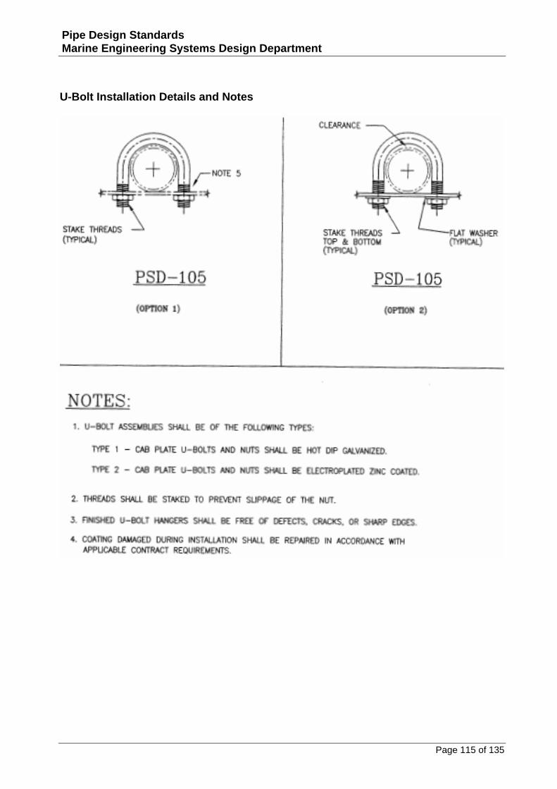
U‐Bolt Installation Details and Notes ..............................................................................................115
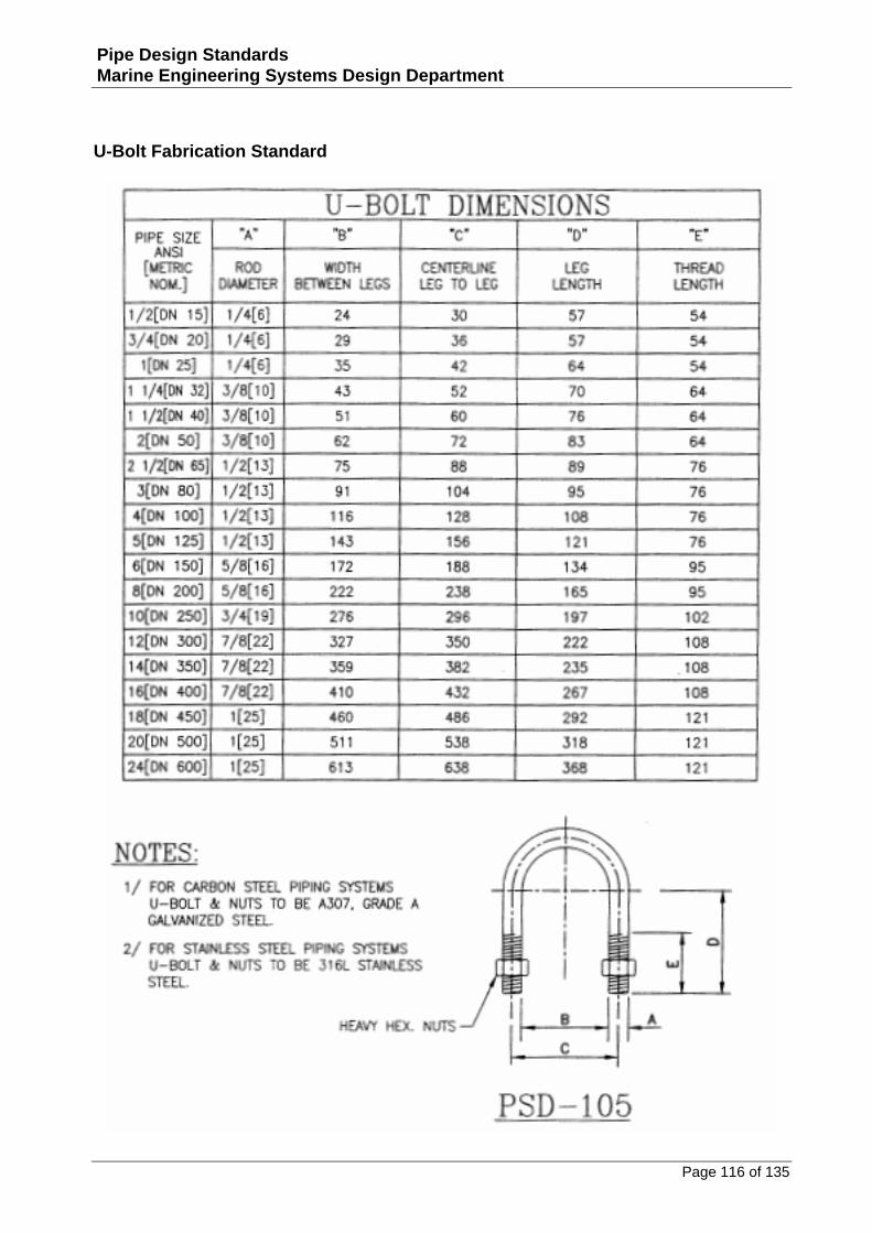
U‐Bolt Fabrication Standard............................................................................................................116
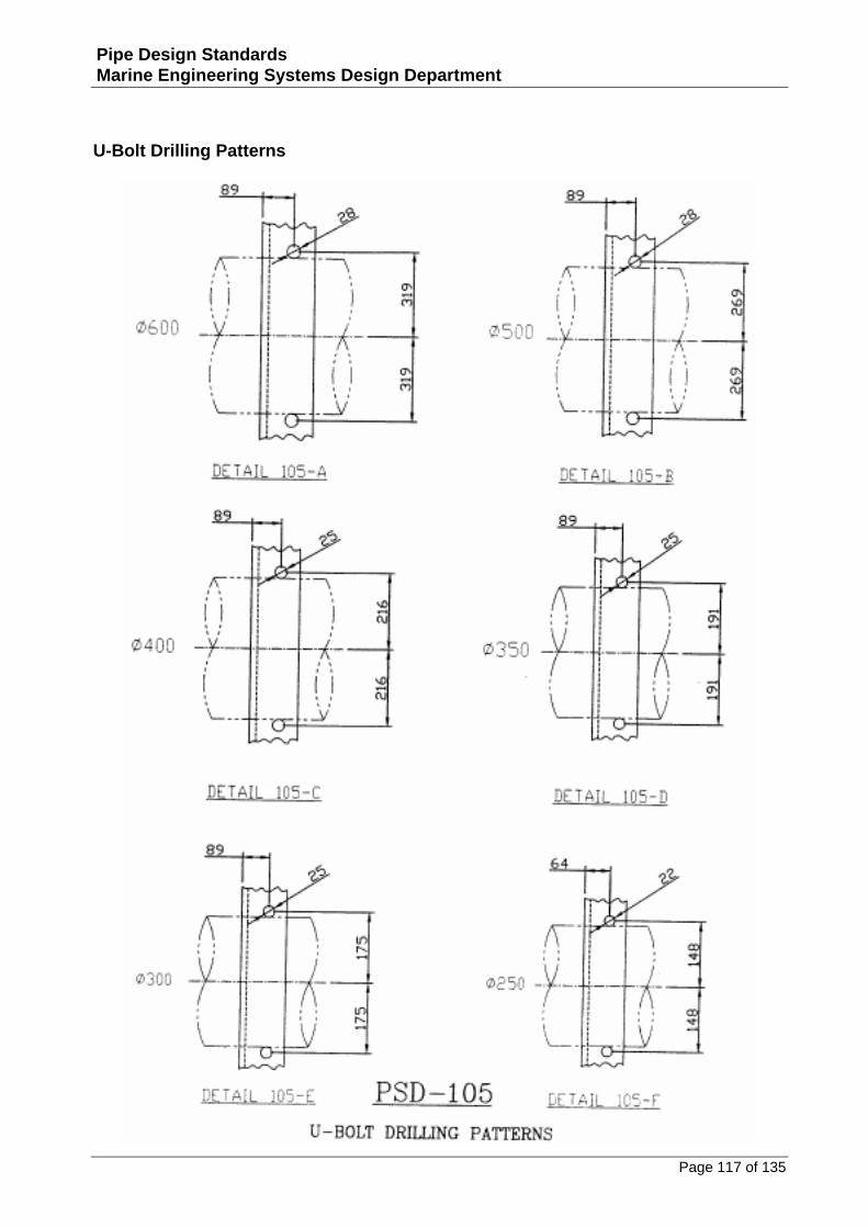
U‐Bolt Drilling Patterns ...................................................................................................................117
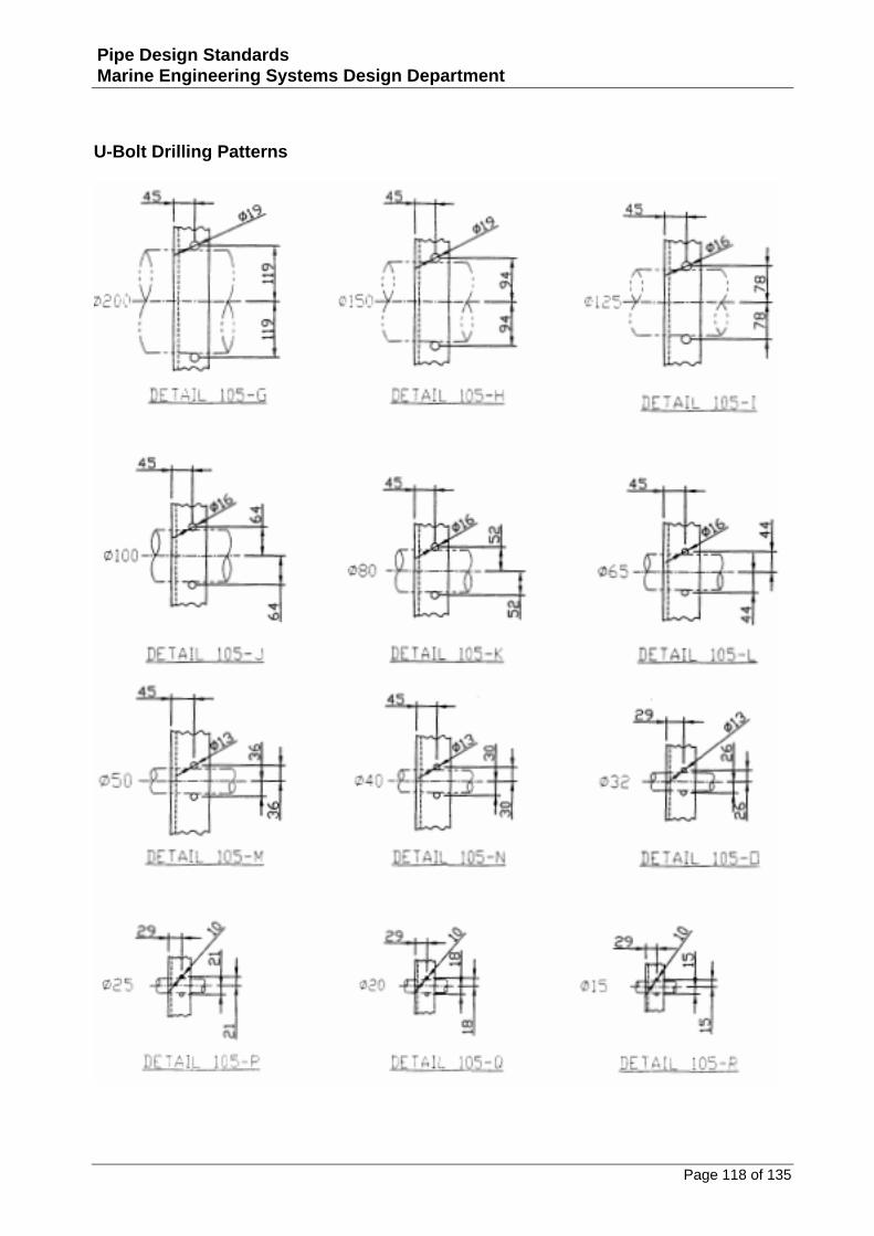
U‐Bolt Drilling Patterns ...................................................................................................................118
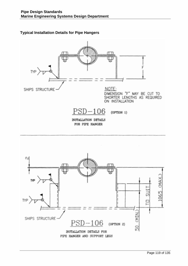
Typical Installation Details for Pipe Hangers....................................................................................119
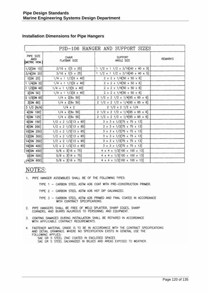
Installation Dimensions for Pipe Hangers ........................................................................................120
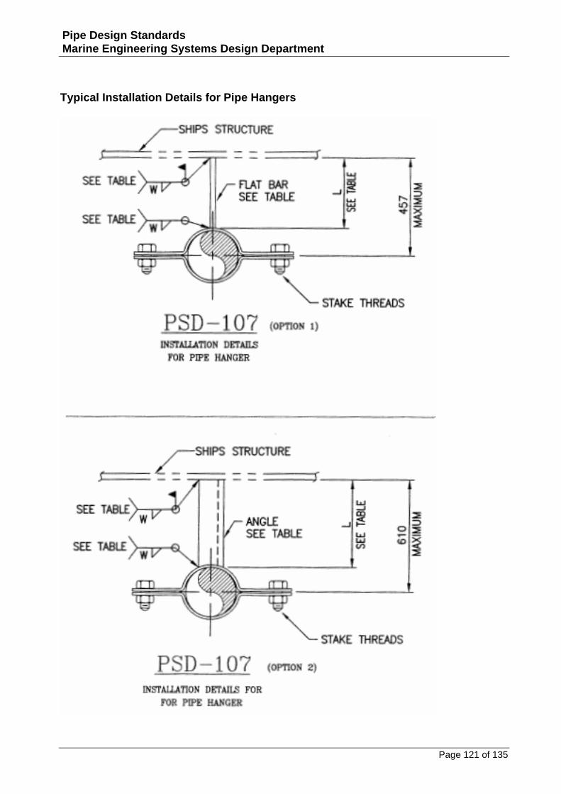
Typical Installation Details for Pipe Hangers....................................................................................121
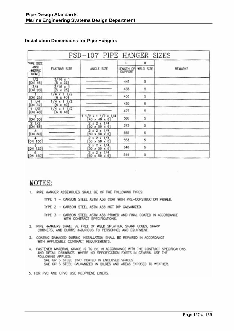
Installation Dimensions for Pipe Hangers ........................................................................................122
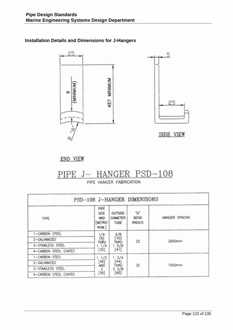
Installation Details and Dimensions for J‐Hangers ...........................................................................123
Installation Details for J‐Hangers with Insulation ............................................................................124
Installation Notes for J‐Hangers ......................................................................................................125
Installation Details and Dimensions for Key Hangers.......................................................................126
Notes for Key Lock‐Hangers ............................................................................................................127
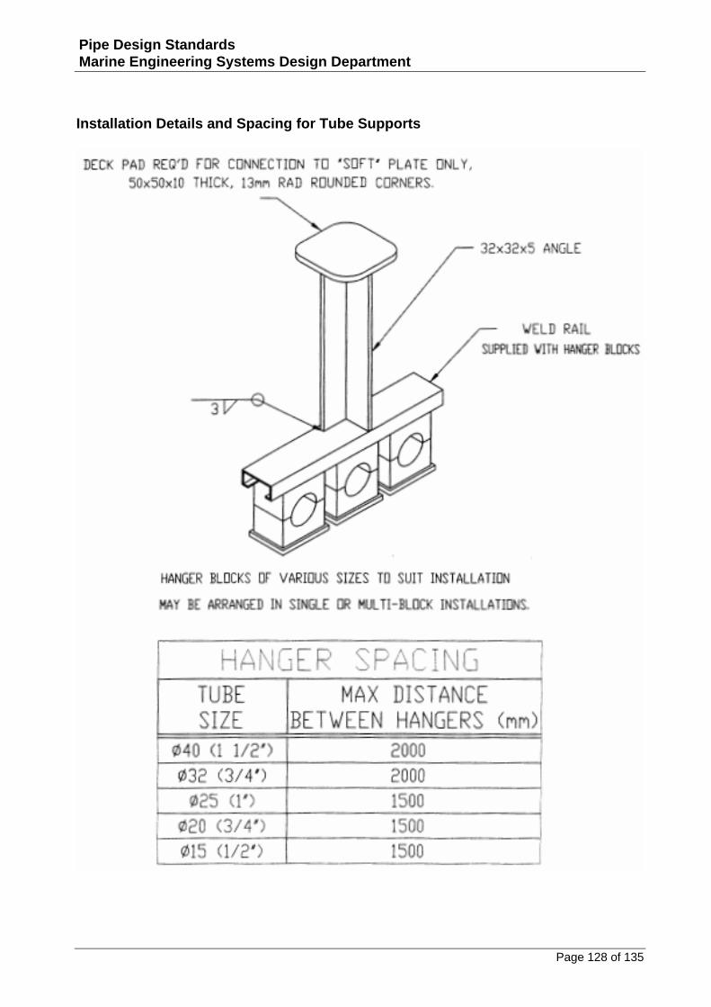
Installation Details and Spacing for Tube Supports..........................................................................128
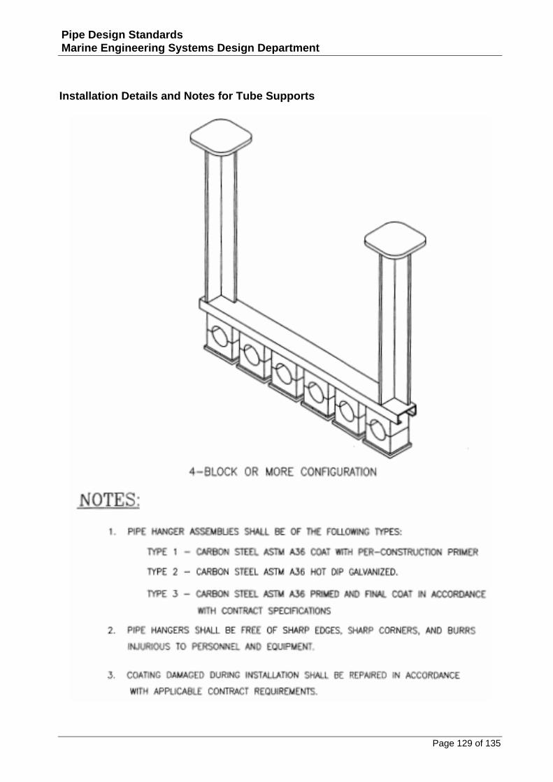
Installation Details and Notes for Tube Supports ............................................................................129
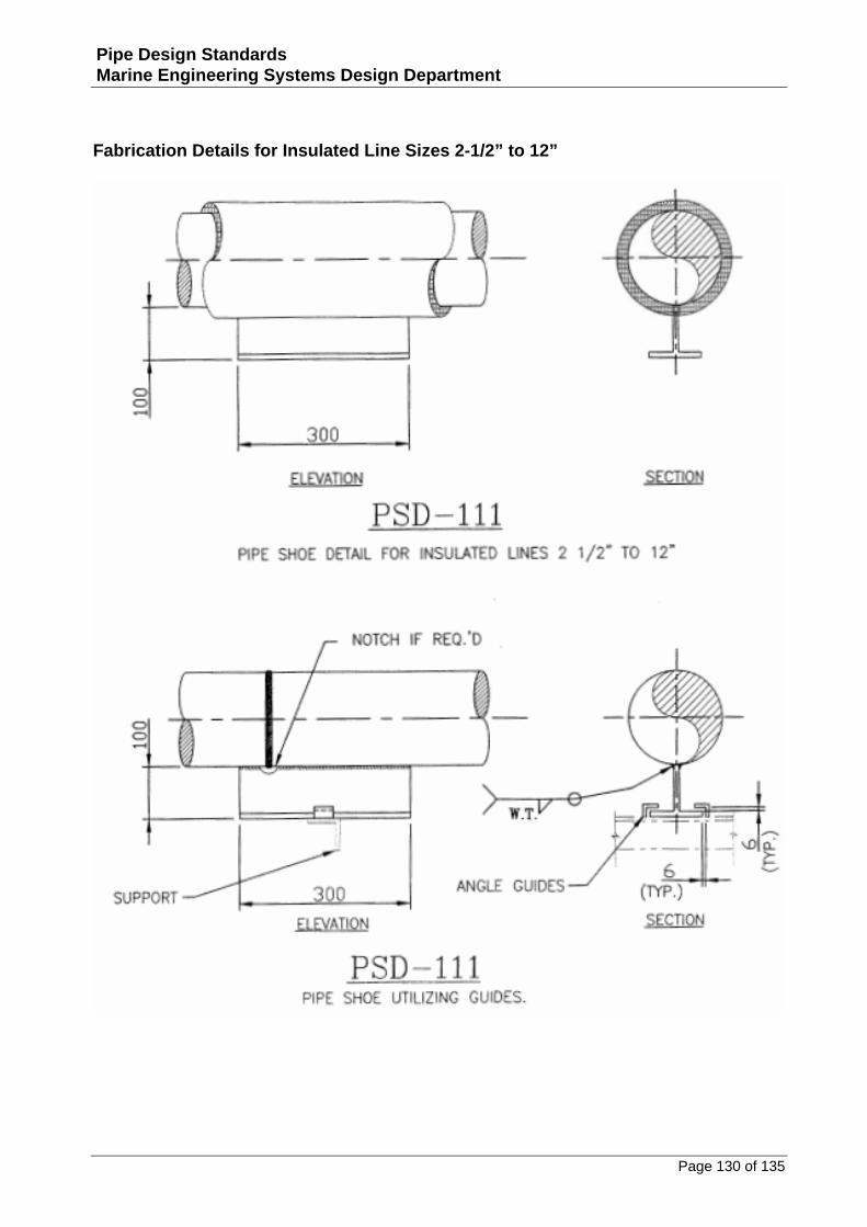
Fabrication Details for Insulated Line Sizes 2‐1/2” to 12” ................................................................130
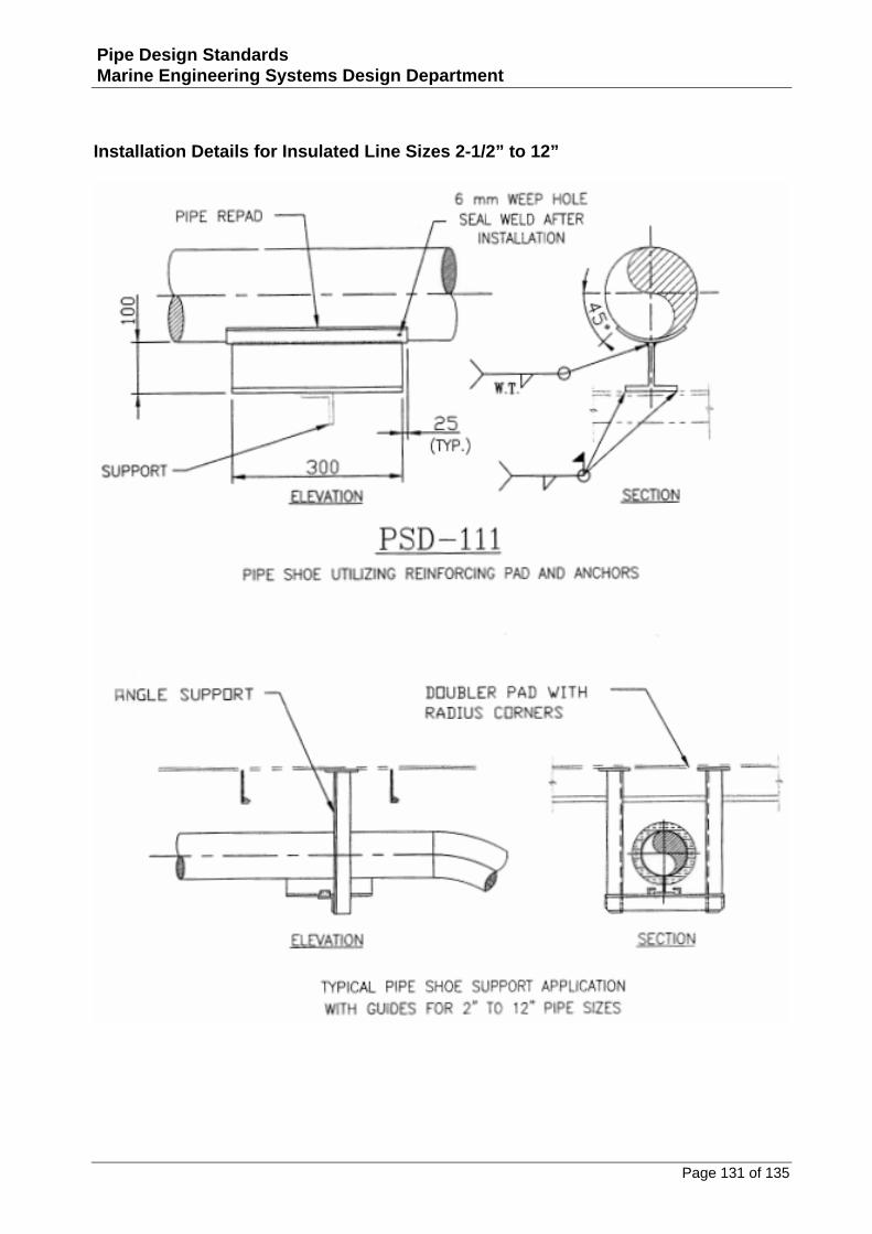
Installation Details for Insulated Line Sizes 2‐1/2” to 12” ................................................................131
Installation Details and Notes for Pipe Shoes ..................................................................................132
Fabrication Details for Insulated Line Sizes 12” and Above ..............................................................133
Page 7 of 135
Pipe Design Standards Marine Engineering Systems Design Department
Installation Details and Notes for Pipe Shoes ..................................................................................134
Installation Details for Insulated Lines 2” and Below.......................................................................135
Page 8 of 135
Pipe Design Standards Marine Engineering Systems Design Department
General Notes: 1. DIMENSIONS ARE GIVEN IN MILLIMETRES, UNLESS NOTED OTHERWISE. 2. THIS STANDARD WAS DEVELOPED FOR PIPING SYSTEMS THAT HAVE 150# AND
300# PRESSURE RATINGS. SOME DETAIL PRINCIPLES MAY BE USED FOR HIGHER RATED SYSTEMS, HOWEVER, CONSULT WITH THE APPLICABLE REGULATORY BODY BEFORE FABRICATION.
3. PIPING STANDARD DETAILS INDICATE MINIMUM REQUIREMENTS ADHERED TO
AND MAY NOT REFLECT ACTUAL CONDITIONS WHERE INSTALLATION IS SUBJECT TO LOCAL VARIATIONS.
4. WHERE CONTRACTUAL INFORMATION CONFLICTS WITH STANDARD DETAILS,
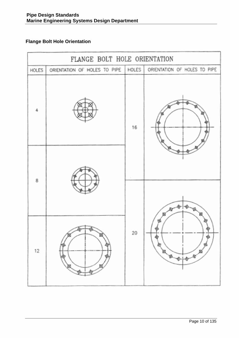
THE CONTRACTUAL INFORMATION SHALL HAVE PRIORITY. 5. FLANGES SHALL BE ORIENTED RELATIVE TO THE PIPE AS SHOWN ON SHEET 05,
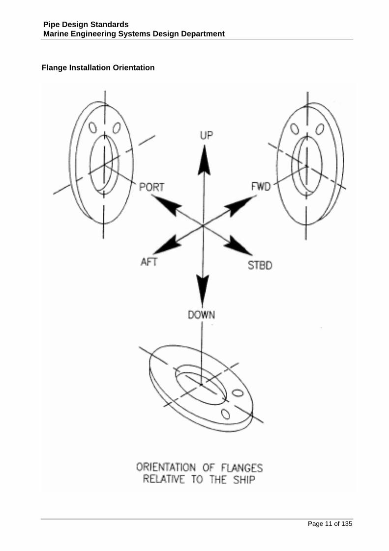
UNLESS OTHERWISE SHOWN ON ARRANGEMENT DRAWING. 6. FLANGES SHALL BE ORIENTED RELATIVE TO THE SHIP AS SHOWN ON SHEET 06,
UNLESS OTHERWISE SHOWN ON ARRANGEMENT DRAWING.
Page 9 of 135
Pipe Design Standards Marine Engineering Systems Design Department
Flanges
Page 10 of 135
Pipe Design Standards Marine Engineering Systems Design Department
Flange Bolt Hole Orientation
Page 11 of 135
Pipe Design Standards Marine Engineering Systems Design Department
Flange Installation Orientation
Page 12 of 135
Pipe Design Standards Marine Engineering Systems Design Department
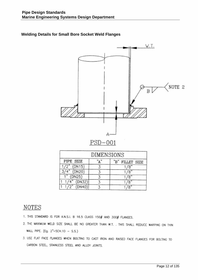
Welding Details for Small Bore Socket Weld Flanges
Page 13 of 135
Pipe Design Standards Marine Engineering Systems Design Department
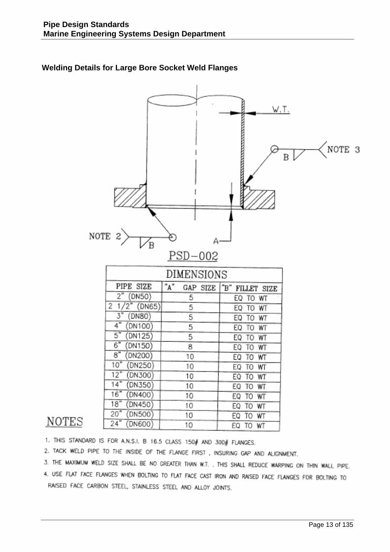
Welding Details for Large Bore Socket Weld Flanges
Page 14 of 135
Pipe Design Standards Marine Engineering Systems Design Department
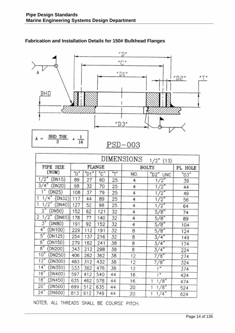
Fabrication and Installation Details for 150# Bulkhead Flanges
Page 15 of 135
Pipe Design Standards Marine Engineering Systems Design Department
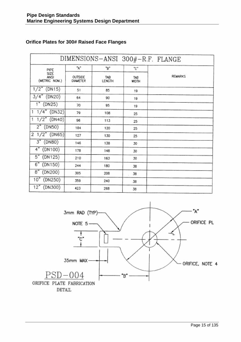
Orifice Plates for 300# Raised Face Flanges
Page 16 of 135
Pipe Design Standards Marine Engineering Systems Design Department
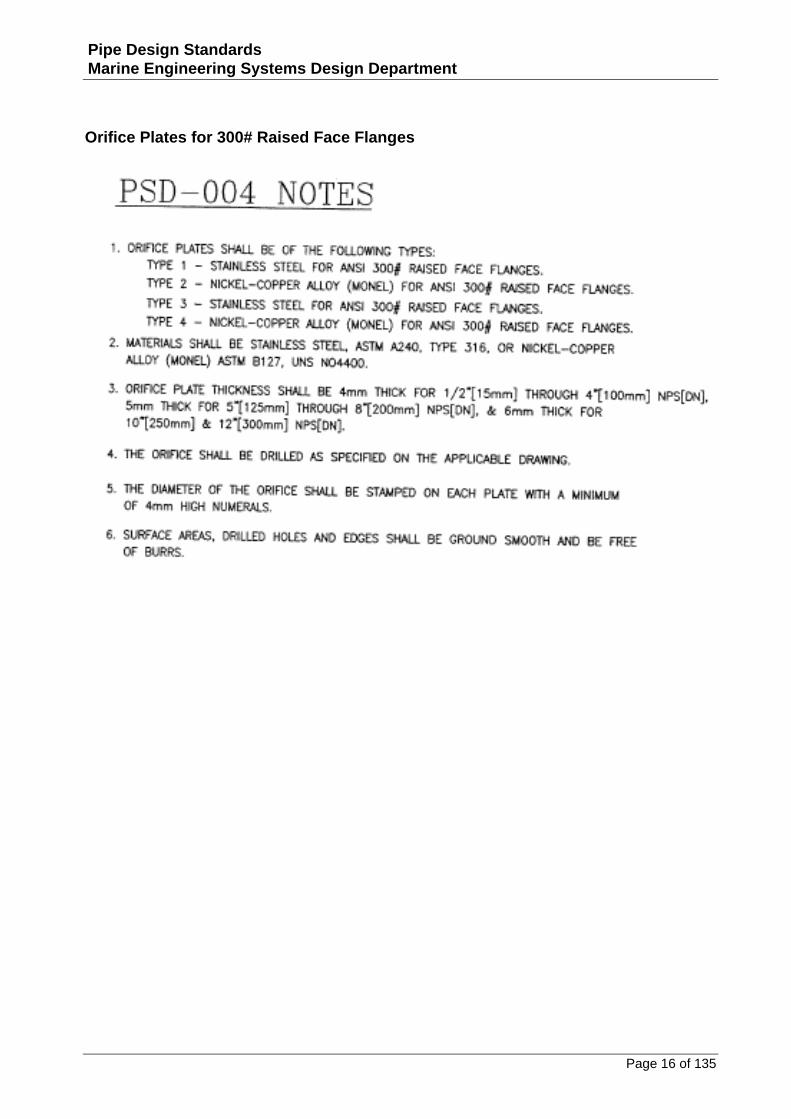
Orifice Plates for 300# Raised Face Flanges
Page 17 of 135
Pipe Design Standards Marine Engineering Systems Design Department
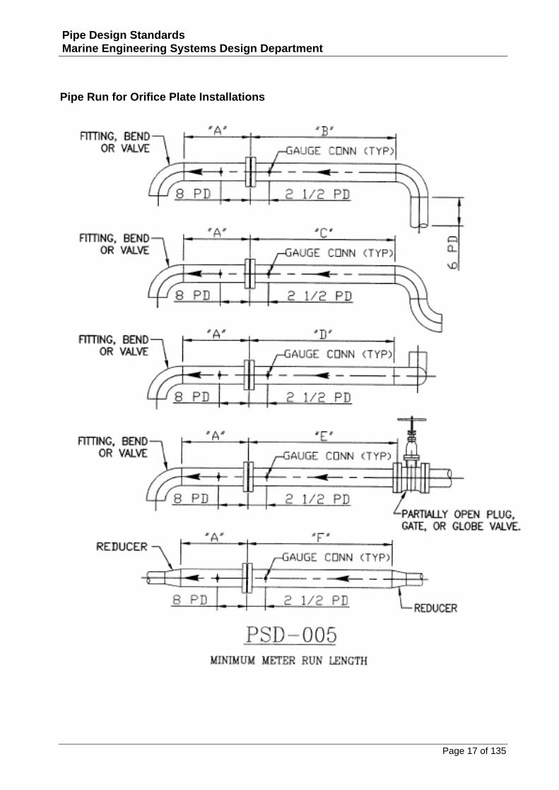
Pipe Run for Orifice Plate Installations
Page 18 of 135
Pipe Design Standards Marine Engineering Systems Design Department
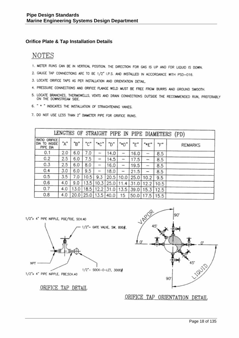
Orifice Plate & Tap Installation Details
Page 19 of 135
Pipe Design Standards Marine Engineering Systems Design Department
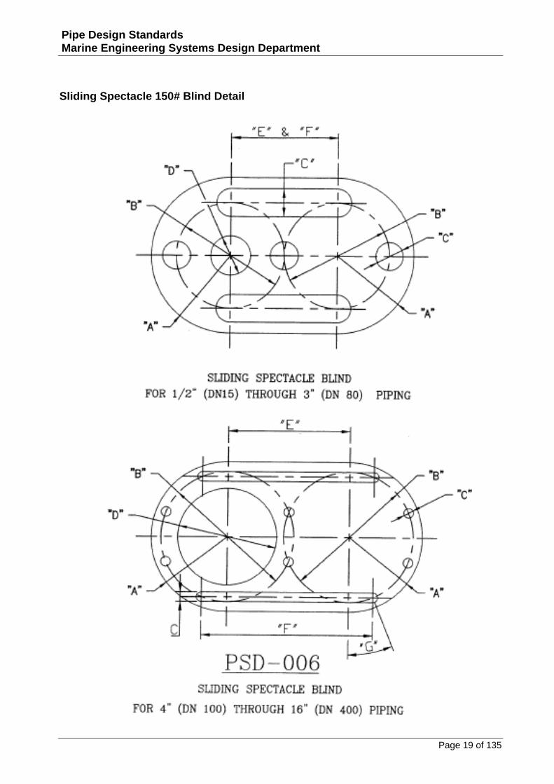
Sliding Spectacle 150# Blind Detail
Page 20 of 135
Pipe Design Standards Marine Engineering Systems Design Department
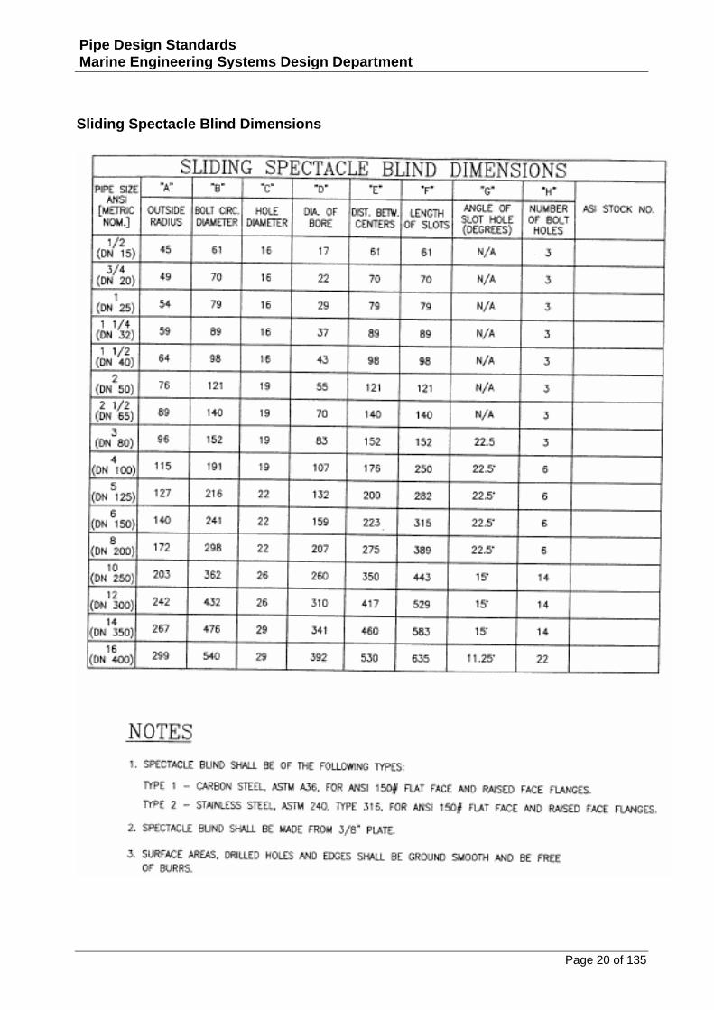
Sliding Spectacle Blind Dimensions
Page 21 of 135
Pipe Design Standards Marine Engineering Systems Design Department
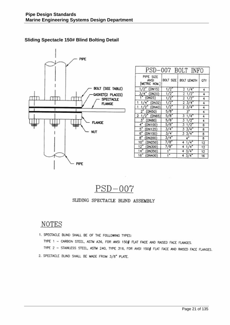
Sliding Spectacle 150# Blind Bolting Detail
Page 22 of 135
Pipe Design Standards Marine Engineering Systems Design Department
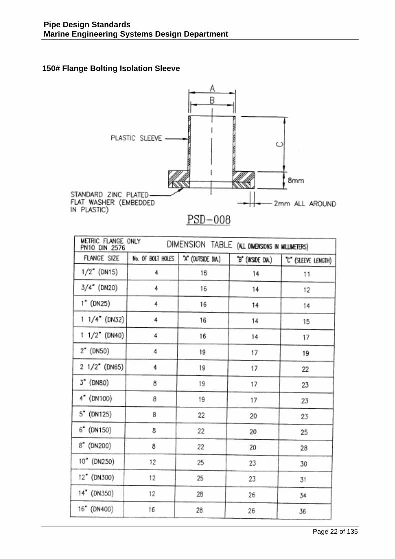
150# Flange Bolting Isolation Sleeve
Page 23 of 135
Pipe Design Standards Marine Engineering Systems Design Department
Pipe and Fitting Details
Page 24 of 135
Pipe Design Standards Marine Engineering Systems Design Department
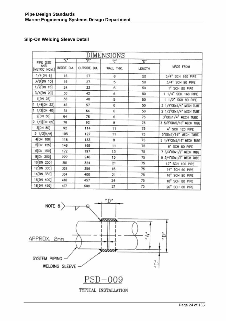
Slip-On Welding Sleeve Detail
Page 25 of 135
Pipe Design Standards Marine Engineering Systems Design Department
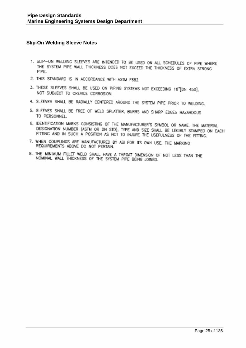
Slip-On Welding Sleeve Notes
Page 26 of 135
Pipe Design Standards Marine Engineering Systems Design Department
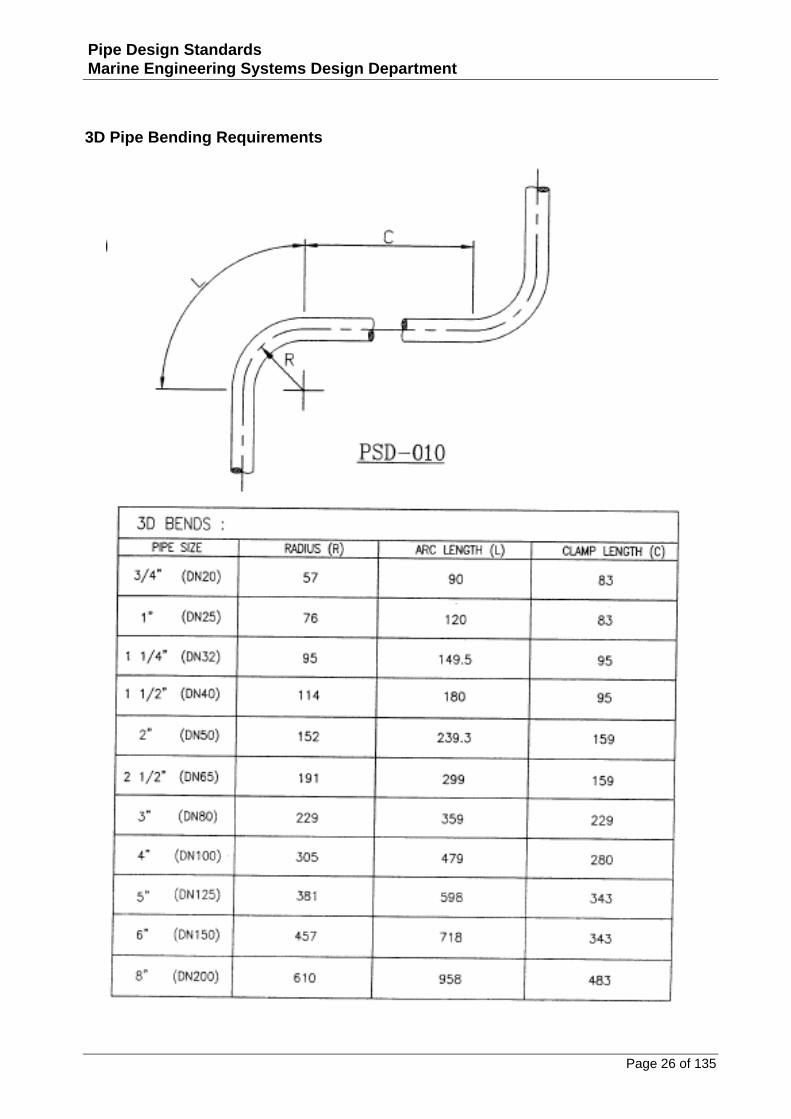
3D Pipe Bending Requirements
Page 27 of 135
Pipe Design Standards Marine Engineering Systems Design Department
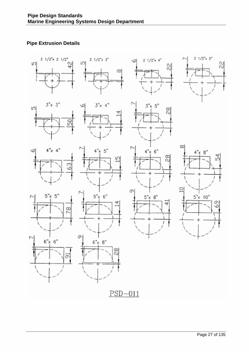
Pipe Extrusion Details
Page 28 of 135
Pipe Design Standards Marine Engineering Systems Design Department
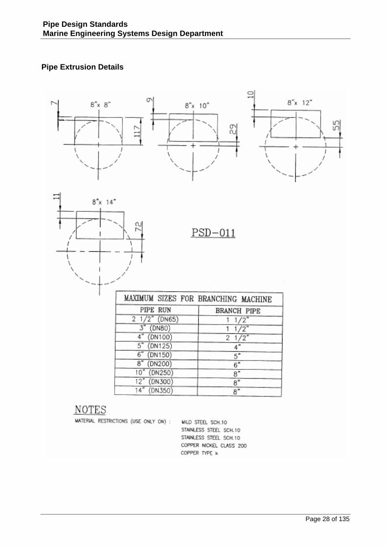
Pipe Extrusion Details
Page 29 of 135
Pipe Design Standards Marine Engineering Systems Design Department
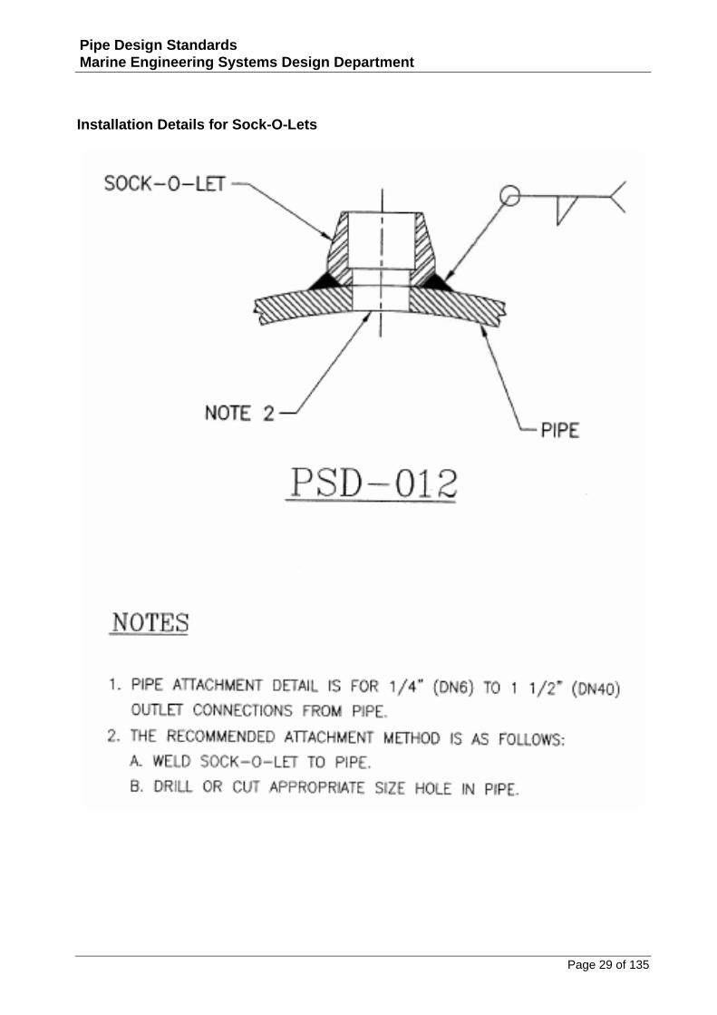
Installation Details for Sock-O-Lets
Page 30 of 135
Pipe Design Standards Marine Engineering Systems Design Department
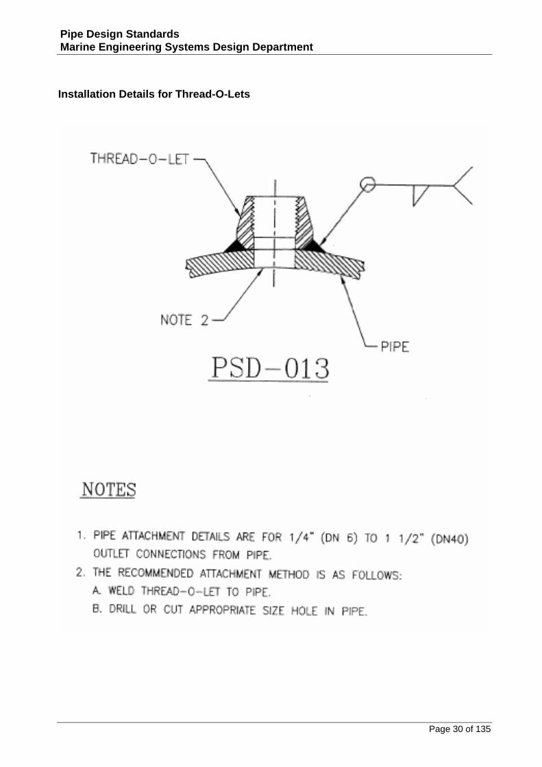
Installation Details for Thread-O-Lets
Page 31 of 135
Pipe Design Standards Marine Engineering Systems Design Department
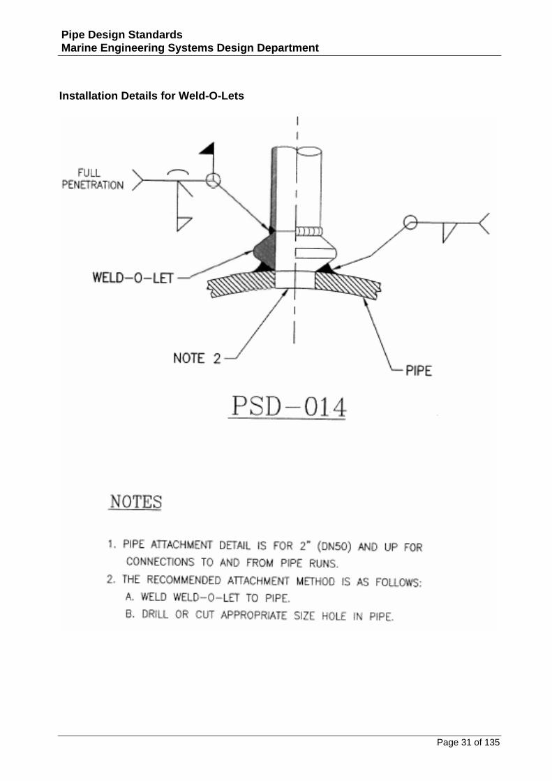
Installation Details for Weld-O-Lets
Page 32 of 135
Pipe Design Standards Marine Engineering Systems Design Department
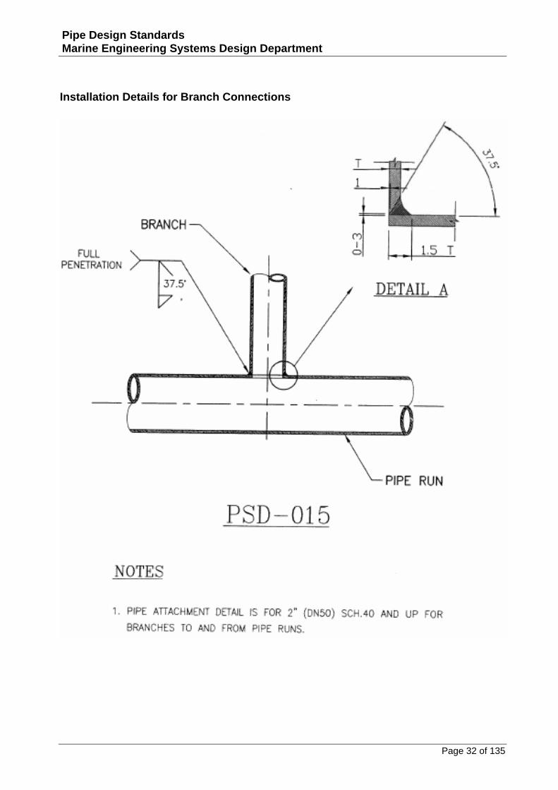
Installation Details for Branch Connections
Page 33 of 135
Pipe Design Standards Marine Engineering Systems Design Department
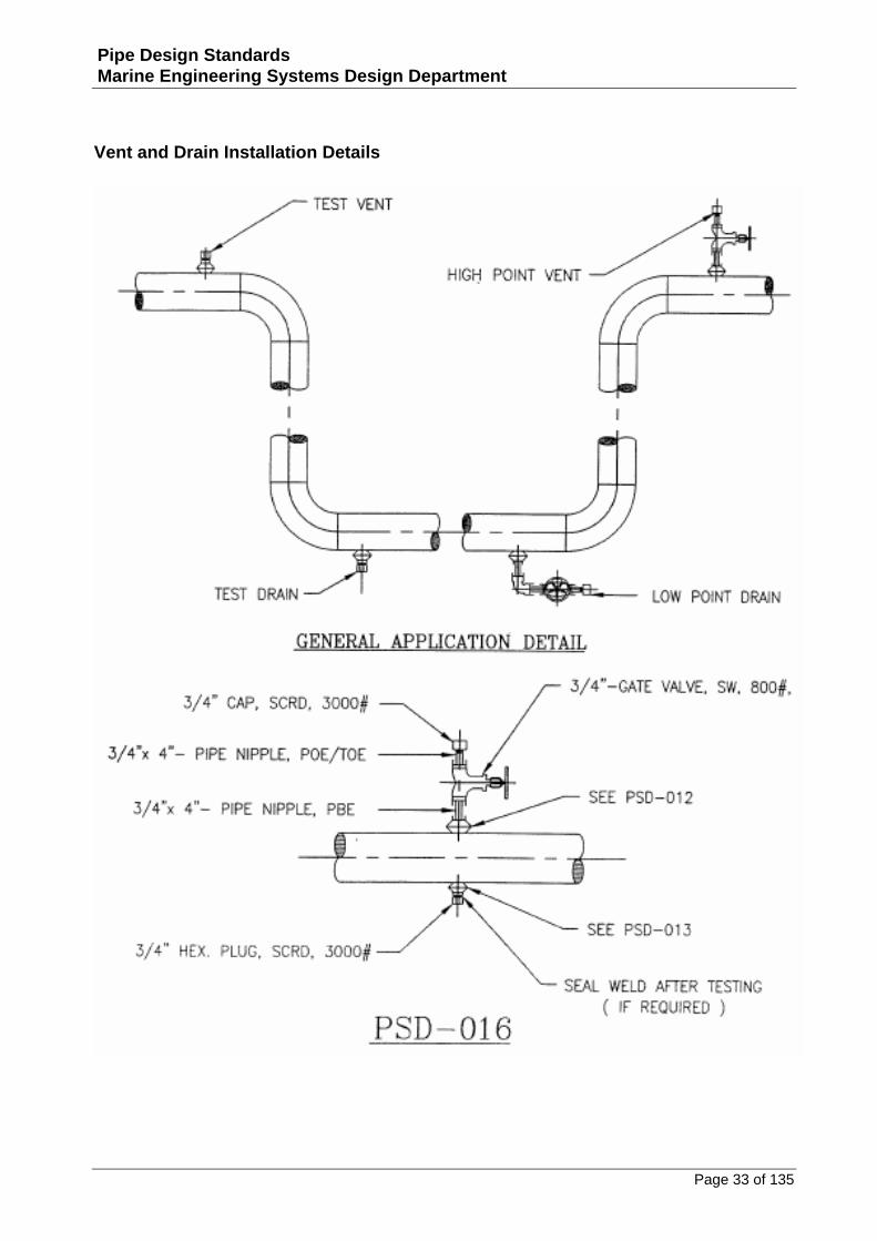
Vent and Drain Installation Details
Page 34 of 135
Pipe Design Standards Marine Engineering Systems Design Department
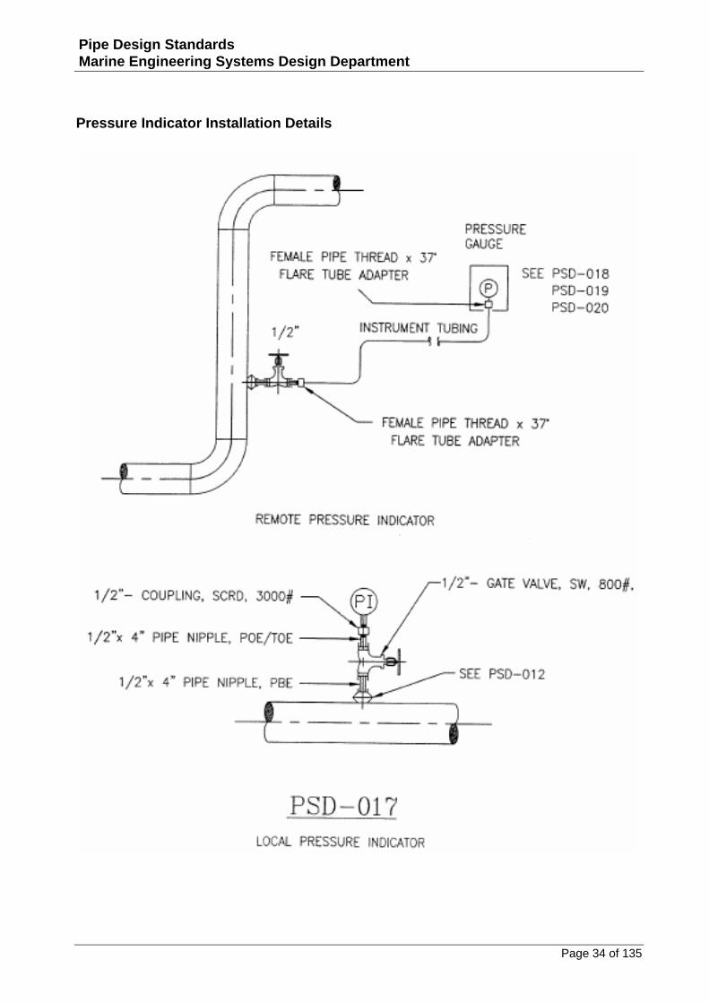
Pressure Indicator Installation Details
Page 35 of 135
Pipe Design Standards Marine Engineering Systems Design Department
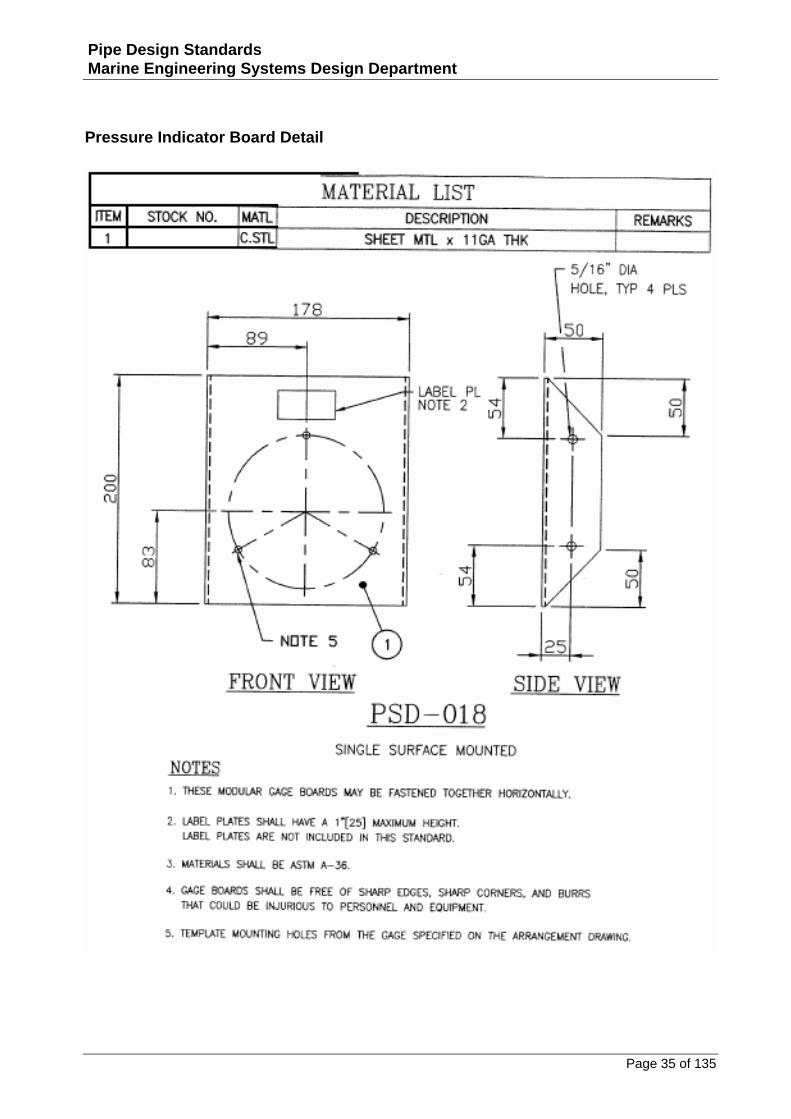
Pressure Indicator Board Detail
Page 36 of 135
Pipe Design Standards Marine Engineering Systems Design Department
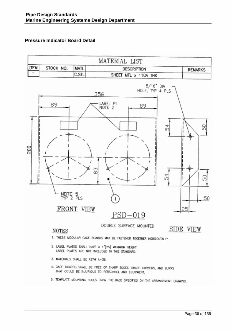
Pressure Indicator Board Detail
Page 37 of 135
Pipe Design Standards Marine Engineering Systems Design Department
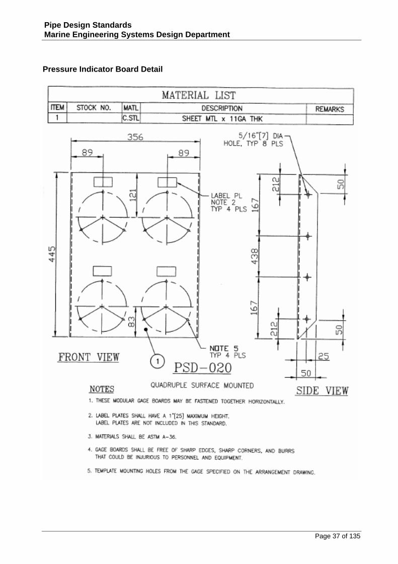
Pressure Indicator Board Detail
Page 38 of 135
Pipe Design Standards Marine Engineering Systems Design Department
Thermowell Pipe Detail Installation
Page 39 of 135
Pipe Design Standards Marine Engineering Systems Design Department
Thermowell Pipe Detail Installation
Page 40 of 135
Pipe Design Standards Marine Engineering Systems Design Department
Thermowell Detail for Tanks Installation

Page 41 of 135
Pipe Design Standards Marine Engineering Systems Design Department
Pressure Vessels
Page 42 of 135
Pipe Design Standards Marine Engineering Systems Design Department
Installation Detail for Level Indicators on Vessels
Page 43 of 135
Pipe Design Standards Marine Engineering Systems Design Department
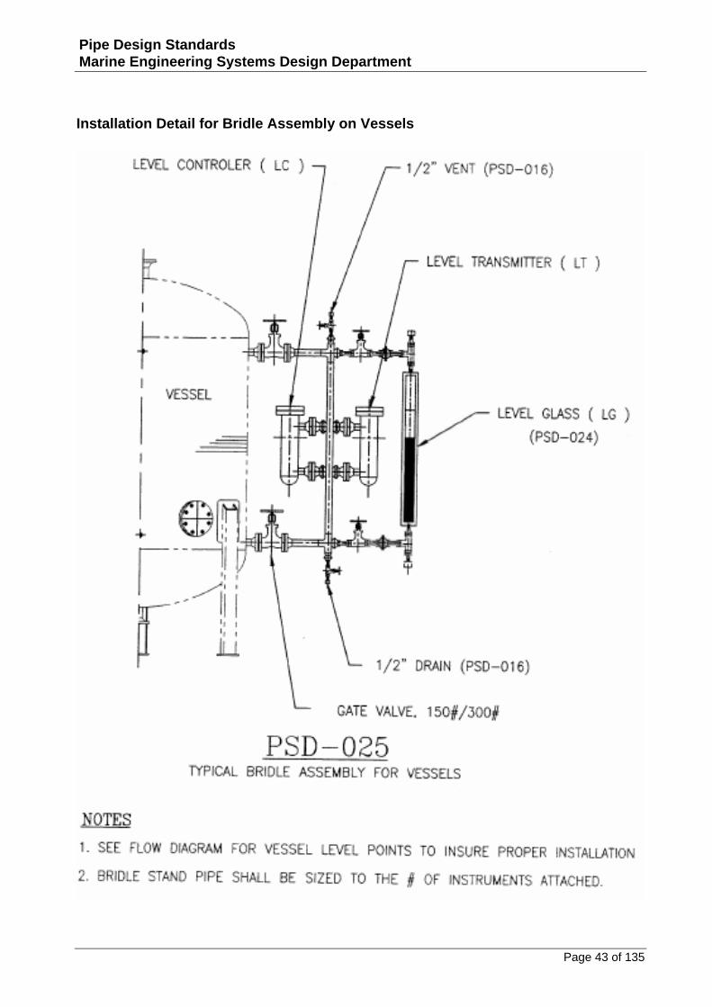
Installation Detail for Bridle Assembly on Vessels
Page 44 of 135
Pipe Design Standards Marine Engineering Systems Design Department
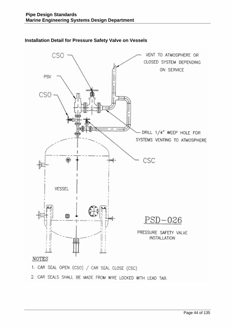
Installation Detail for Pressure Safety Valve on Vessels
Page 45 of 135
Pipe Design Standards Marine Engineering Systems Design Department
Special Connections
Page 46 of 135
Pipe Design Standards Marine Engineering Systems Design Department
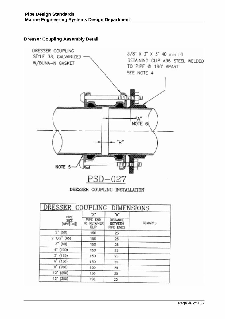
Dresser Coupling Assembly Detail
Page 47 of 135
Pipe Design Standards Marine Engineering Systems Design Department
Dresser Coupling Assembly Notes
Page 48 of 135
Pipe Design Standards Marine Engineering Systems Design Department
Fabrication Detail for International Shore Connection
Page 49 of 135
Pipe Design Standards Marine Engineering Systems Design Department
Overboard Discharge Pipe Welding Detail
Page 50 of 135
Pipe Design Standards Marine Engineering Systems Design Department
Overboard Discharge Pipe and Plate Dimensions
Page 51 of 135
Pipe Design Standards Marine Engineering Systems Design Department
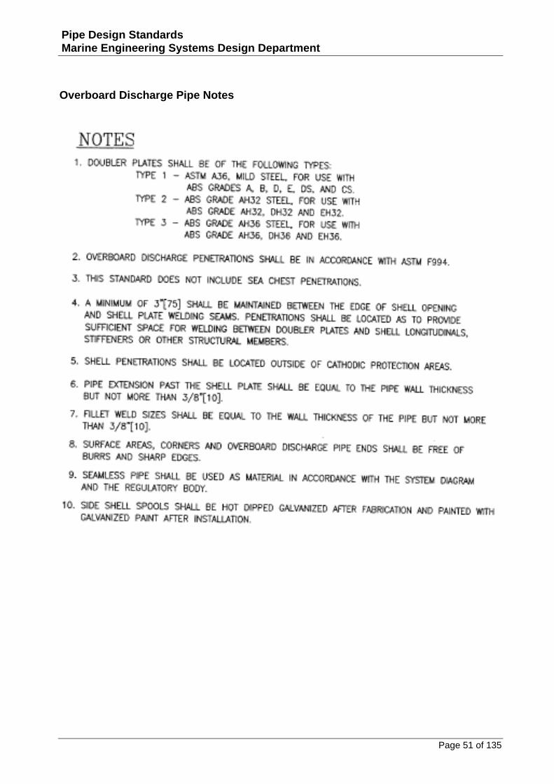
Overboard Discharge Pipe Notes
Page 52 of 135
Pipe Design Standards Marine Engineering Systems Design Department
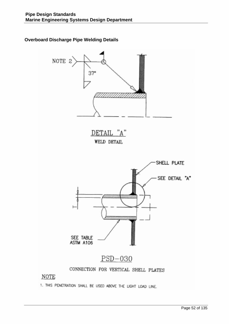
Overboard Discharge Pipe Welding Details
Page 53 of 135
Pipe Design Standards Marine Engineering Systems Design Department
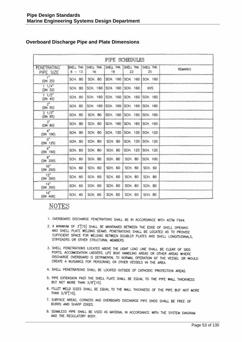
Overboard Discharge Pipe and Plate Dimensions
Page 54 of 135
Pipe Design Standards Marine Engineering Systems Design Department
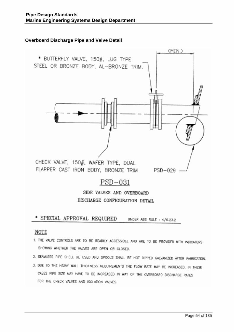
Overboard Discharge Pipe and Valve Detail
Page 55 of 135
Pipe Design Standards Marine Engineering Systems Design Department
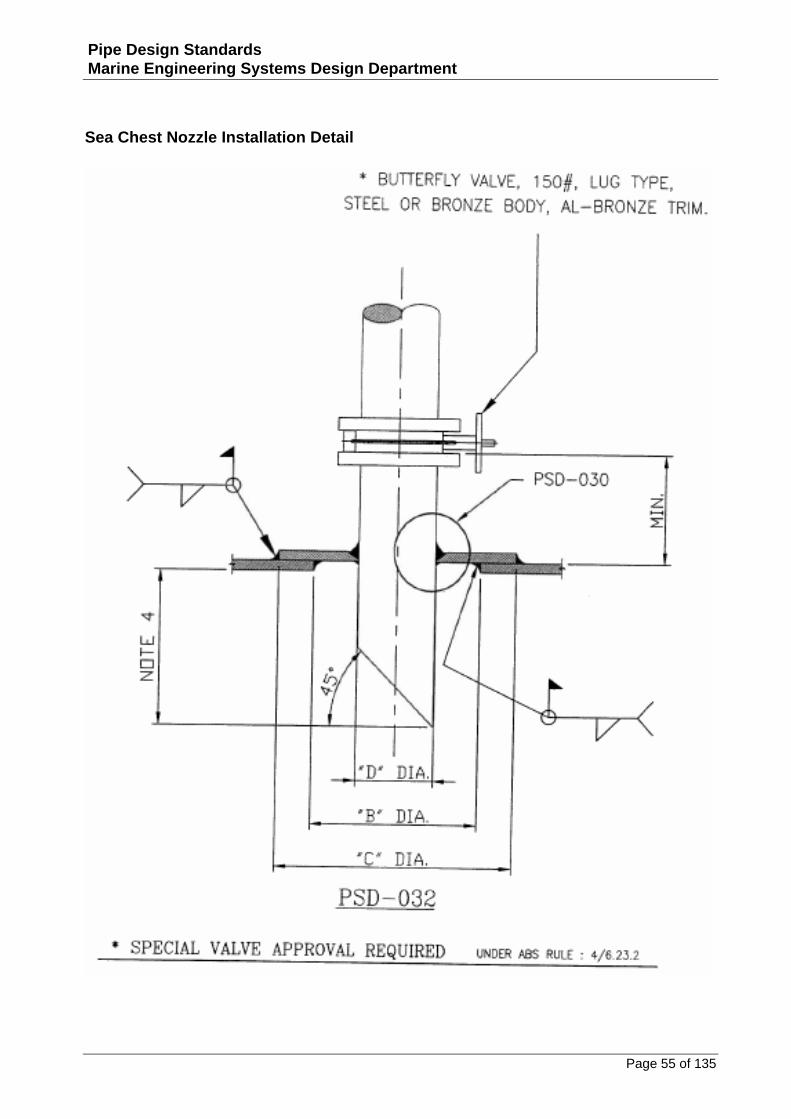
Sea Chest Nozzle Installation Detail
Page 56 of 135
Pipe Design Standards Marine Engineering Systems Design Department
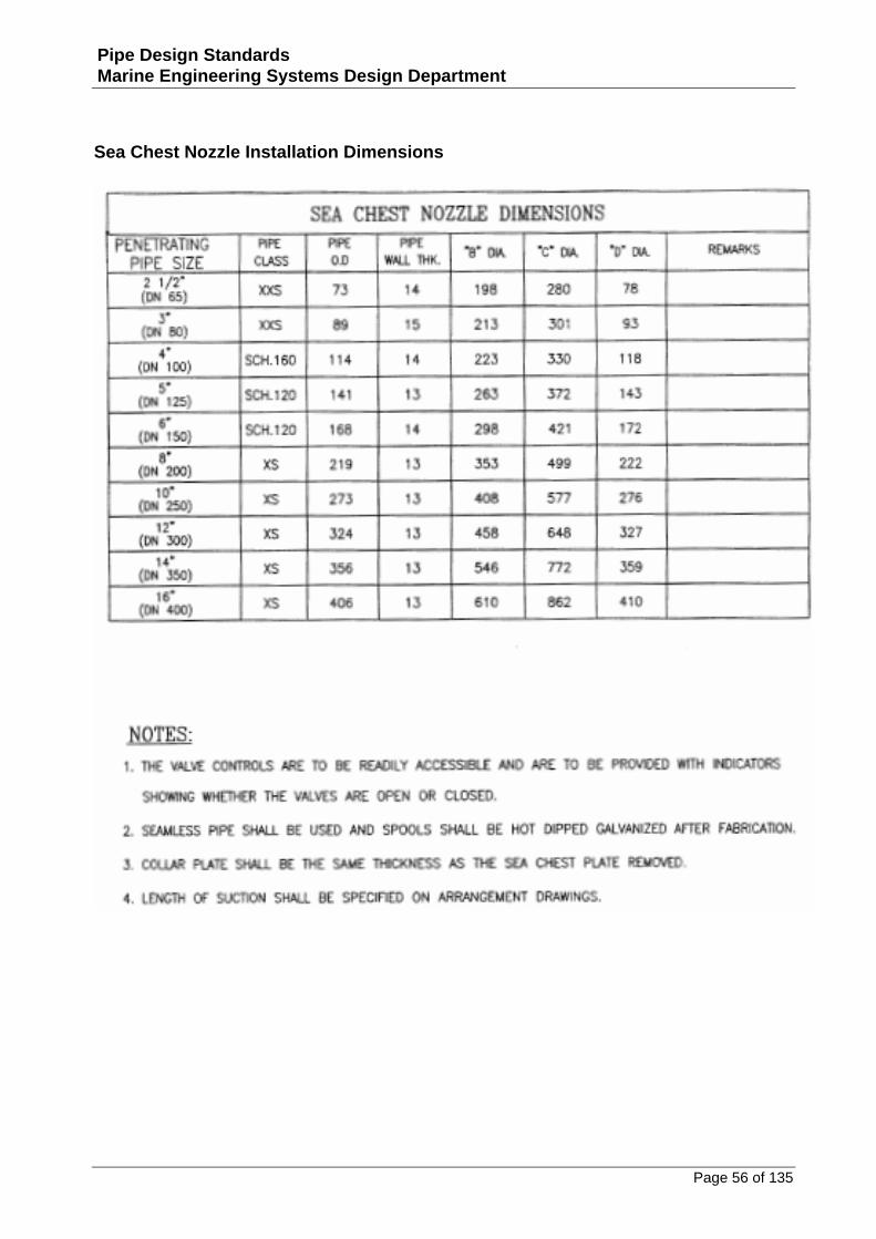
Sea Chest Nozzle Installation Dimensions
Page 57 of 135
Pipe Design Standards Marine Engineering Systems Design Department
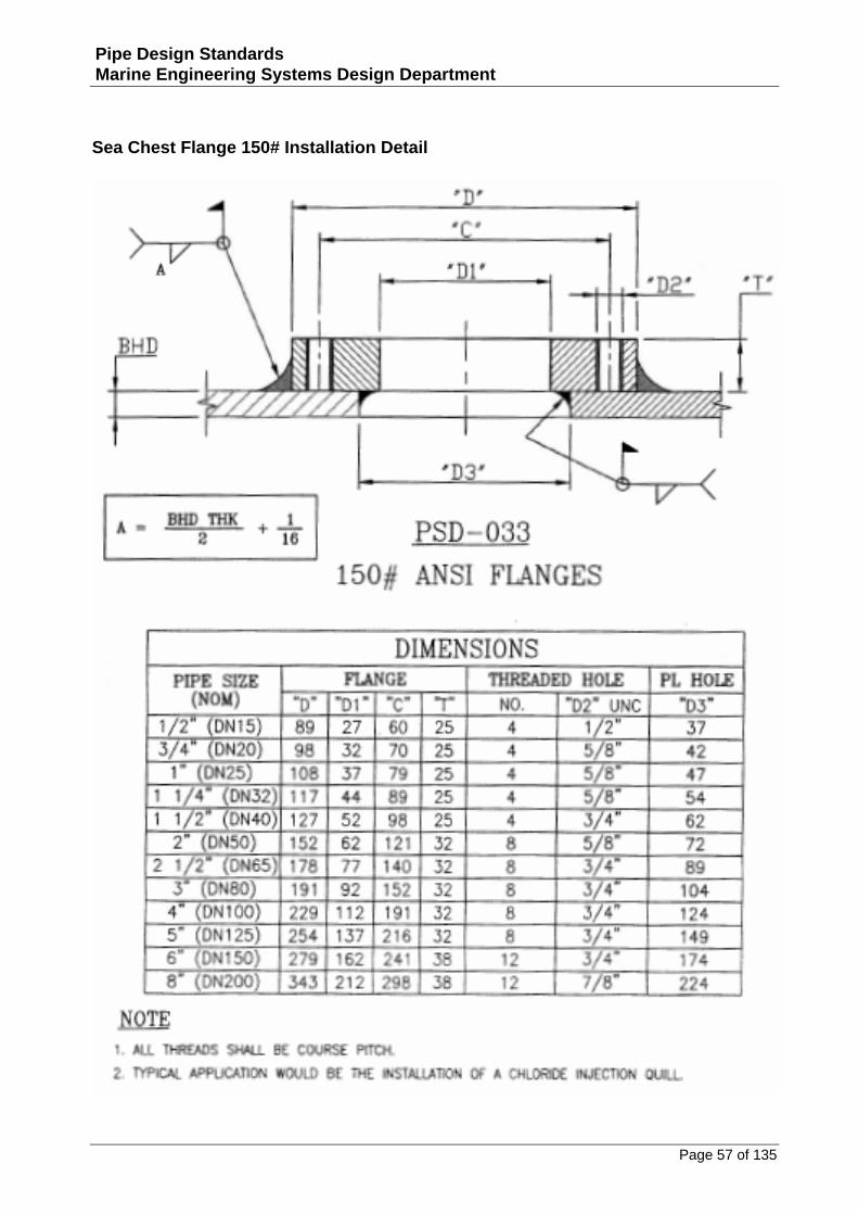
Sea Chest Flange 150# Installation Detail

Page 58 of 135
Pipe Design Standards Marine Engineering Systems Design Department
Bulkhead Penetrations
Page 59 of 135
Pipe Design Standards Marine Engineering Systems Design Department
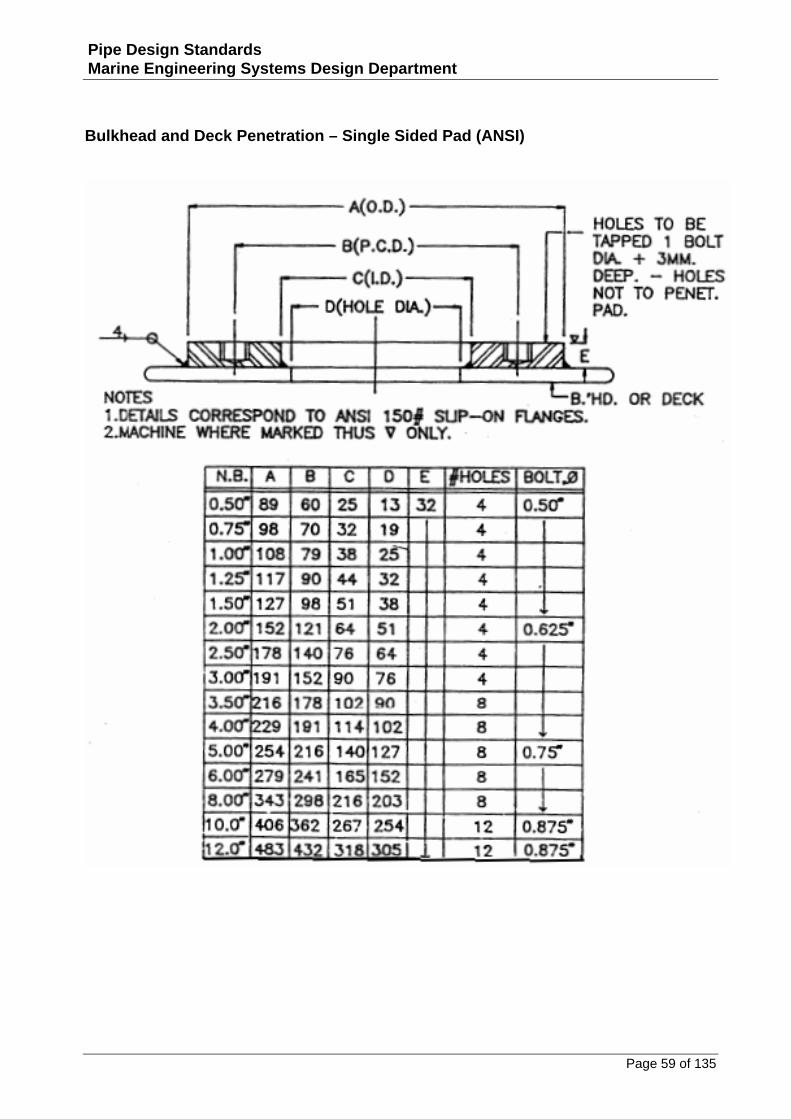
Bulkhead and Deck Penetration – Single Sided Pad (ANSI)
Page 60 of 135
Pipe Design Standards Marine Engineering Systems Design Department
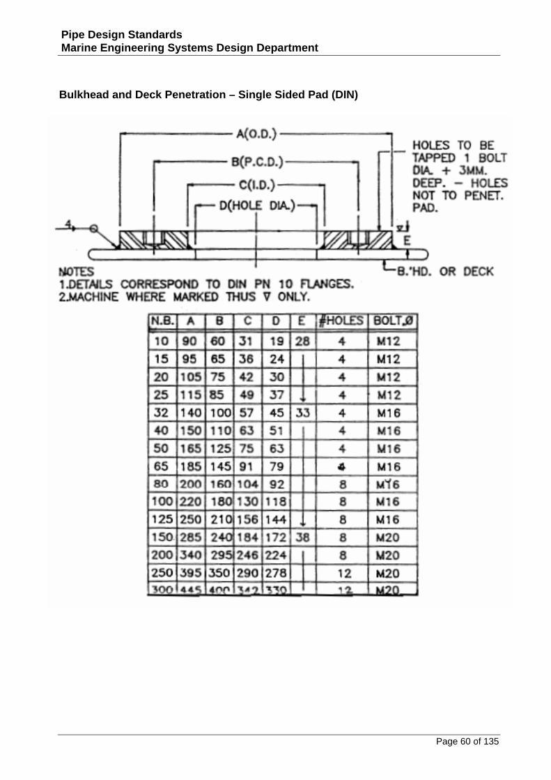
Bulkhead and Deck Penetration – Single Sided Pad (DIN)
Page 61 of 135
Pipe Design Standards Marine Engineering Systems Design Department
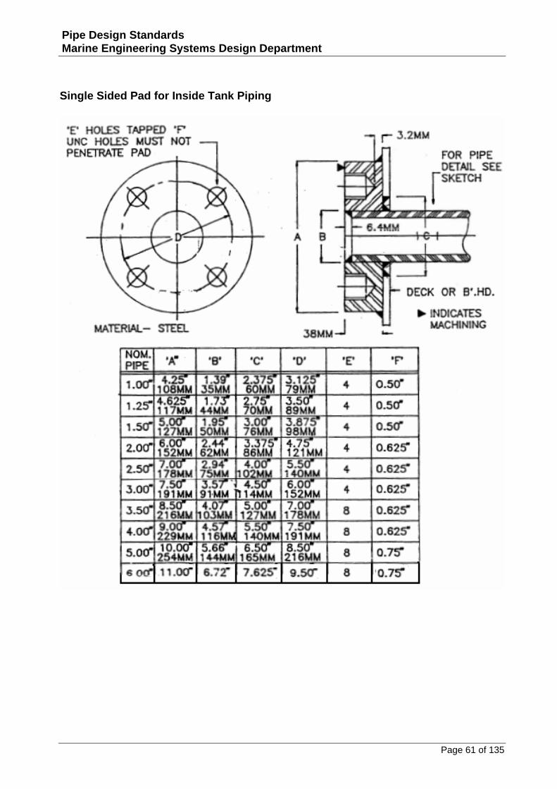
Single Sided Pad for Inside Tank Piping
Page 62 of 135
Pipe Design Standards Marine Engineering Systems Design Department
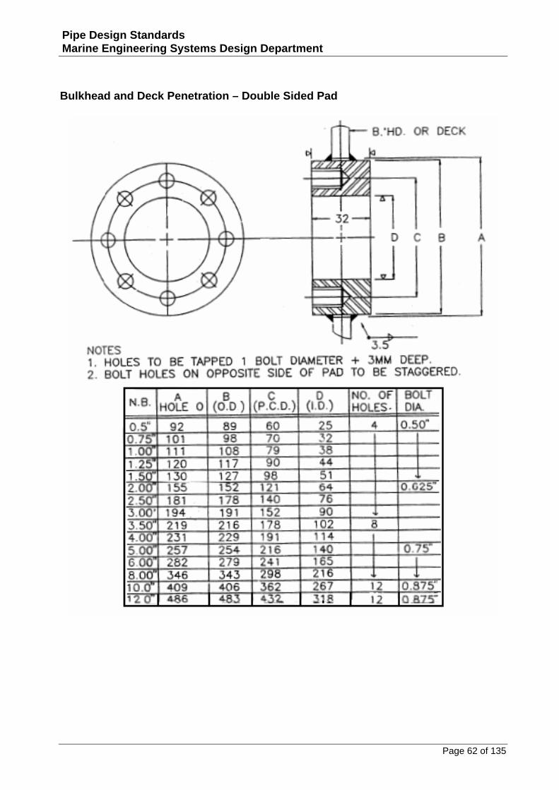
Bulkhead and Deck Penetration – Double Sided Pad
Page 63 of 135
Pipe Design Standards Marine Engineering Systems Design Department
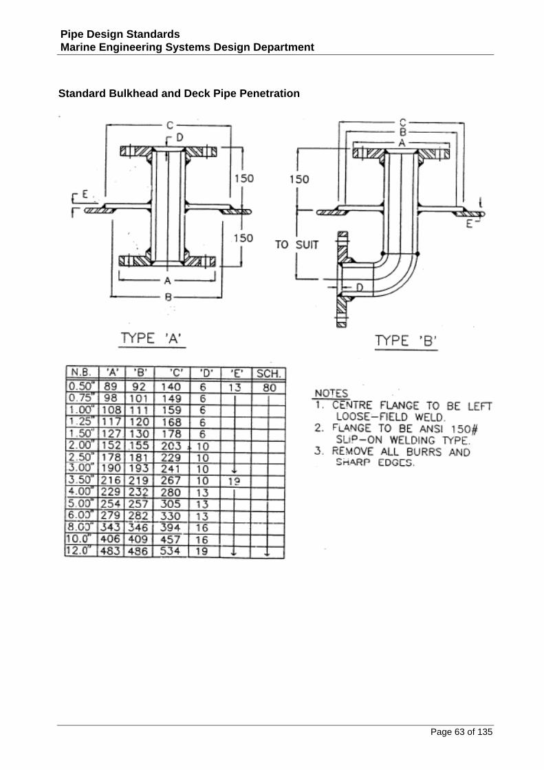
Standard Bulkhead and Deck Pipe Penetration
Page 64 of 135
Pipe Design Standards Marine Engineering Systems Design Department
Bulkhead and Deck Penetration – Pipe Sleeve
Page 65 of 135
Pipe Design Standards Marine Engineering Systems Design Department
Standard Through-Deck Angled Pipe Connection
Page 66 of 135
Pipe Design Standards Marine Engineering Systems Design Department
Standard Penetration – Hydraulic Piping
Page 67 of 135
Pipe Design Standards Marine Engineering Systems Design Department
Copper Pipe Penetration
Page 68 of 135
Pipe Design Standards Marine Engineering Systems Design Department
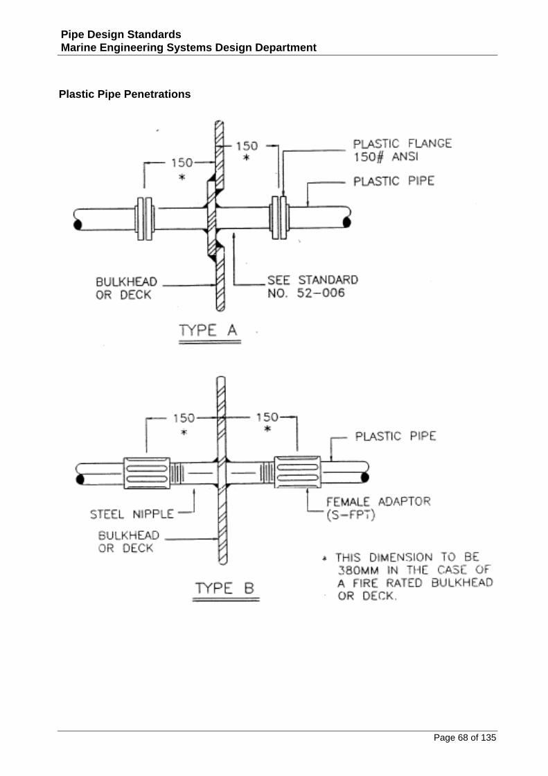
Plastic Pipe Penetrations
Page 69 of 135
Pipe Design Standards Marine Engineering Systems Design Department
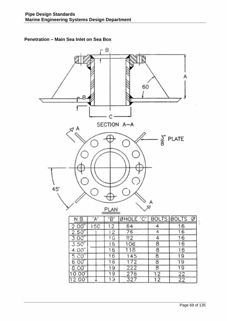
Penetration – Main Sea Inlet on Sea Box
Page 70 of 135
Pipe Design Standards Marine Engineering Systems Design Department
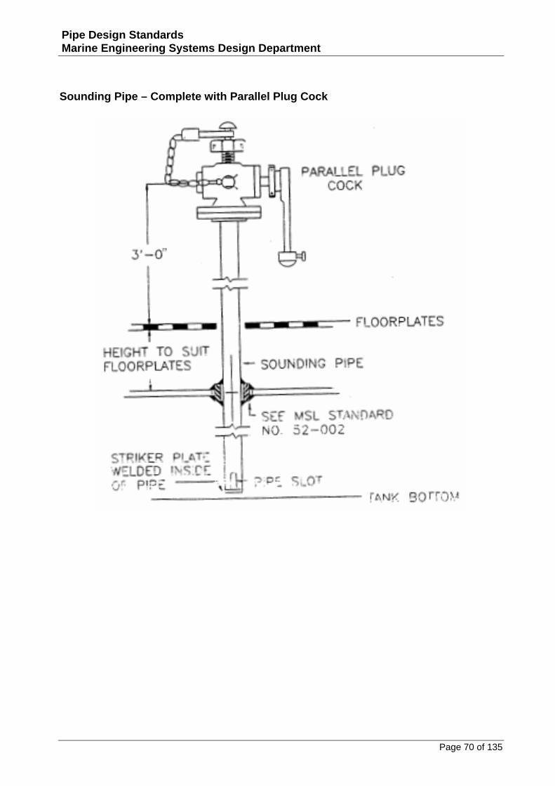
Sounding Pipe – Complete with Parallel Plug Cock
Page 71 of 135
Pipe Design Standards Marine Engineering Systems Design Department
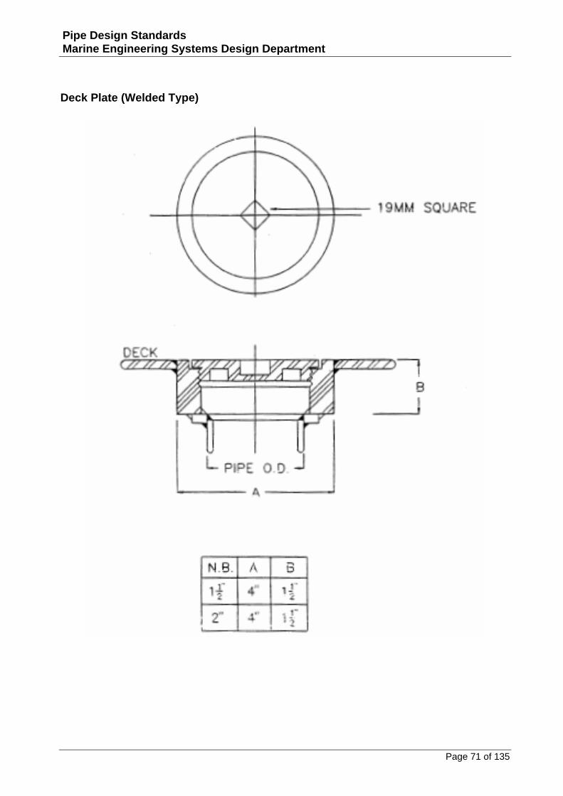
Deck Plate (Welded Type)
Page 72 of 135
Pipe Design Standards Marine Engineering Systems Design Department
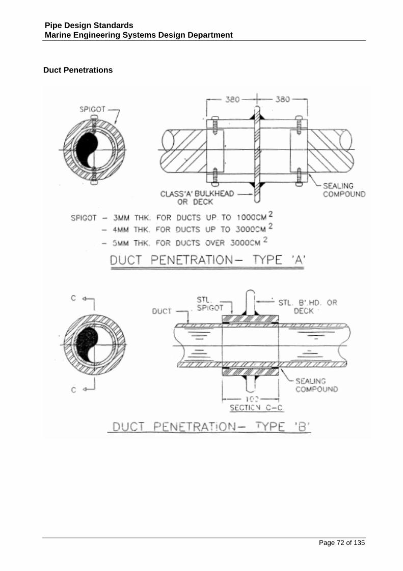
Duct Penetrations
Page 73 of 135
Pipe Design Standards Marine Engineering Systems Design Department
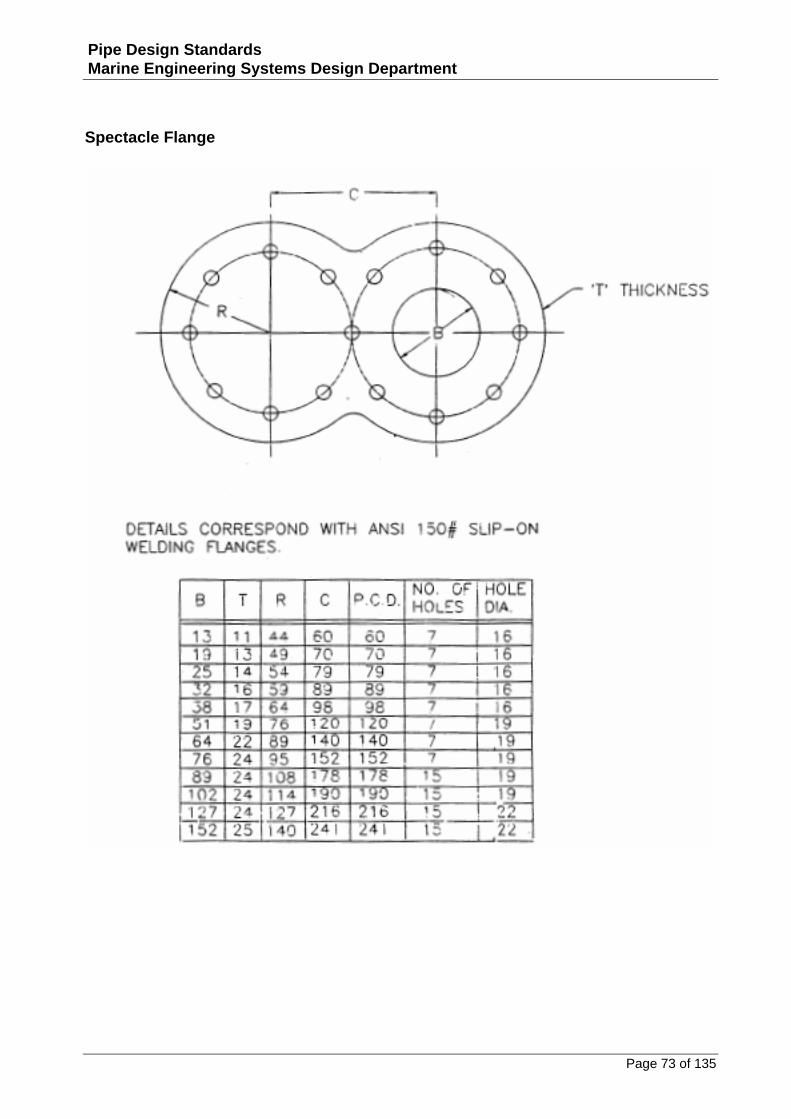
Spectacle Flange
Page 74 of 135
Pipe Design Standards Marine Engineering Systems Design Department
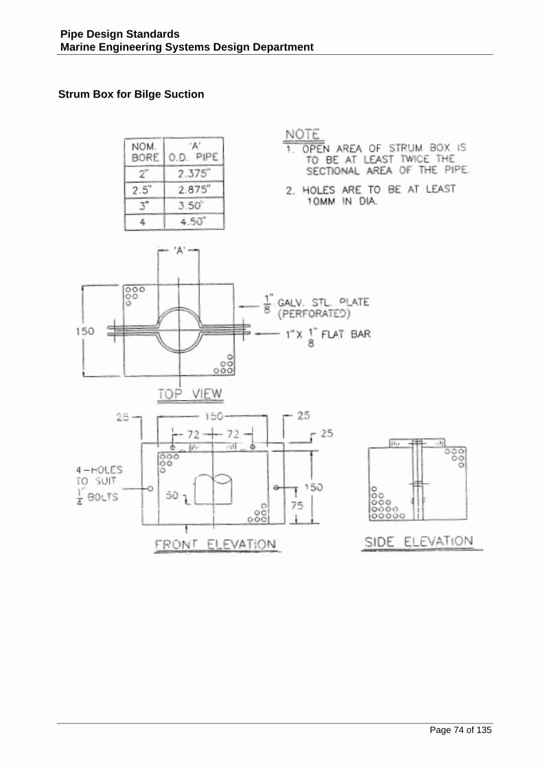
Strum Box for Bilge Suction
Page 75 of 135
Pipe Design Standards Marine Engineering Systems Design Department
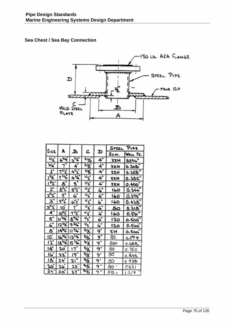
Sea Chest / Sea Bay Connection
Page 76 of 135
Pipe Design Standards Marine Engineering Systems Design Department
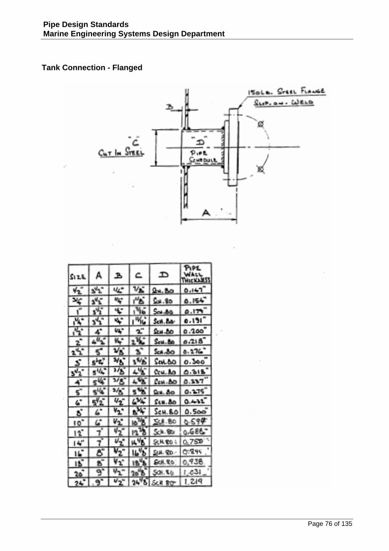
Tank Connection - Flanged
Page 77 of 135
Pipe Design Standards Marine Engineering Systems Design Department
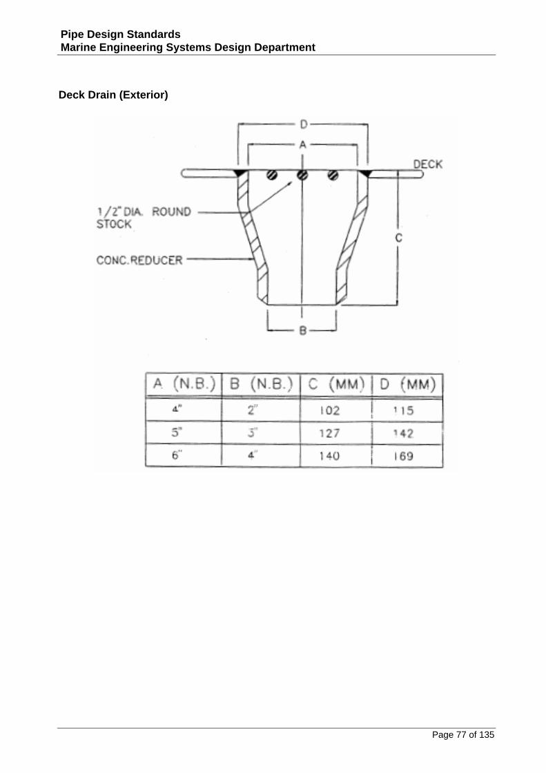
Deck Drain (Exterior)
Page 78 of 135
Pipe Design Standards Marine Engineering Systems Design Department
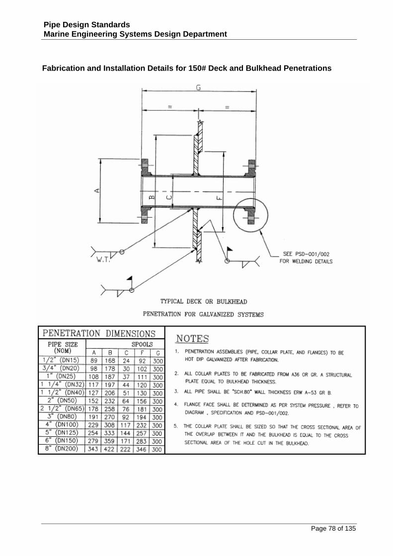
Fabrication and Installation Details for 150# Deck and Bulkhead Penetrations

Page 79 of 135
Pipe Design Standards Marine Engineering Systems Design Department
Fabrication and Installation Details for 150# Deck and Bulkhead Penetrations
Page 80 of 135
Pipe Design Standards Marine Engineering Systems Design Department
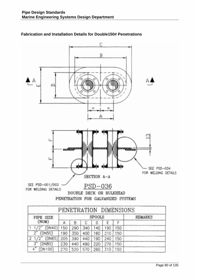
Fabrication and Installation Details for Double150# Penetrations

Page 81 of 135
Pipe Design Standards Marine Engineering Systems Design Department
Fabrication and Installation Details for 3-Way 150# Penetrations
Page 82 of 135
Pipe Design Standards Marine Engineering Systems Design Department
Pipe Sleeve Installation Details for W.T. & O.T. Penetrations
Page 83 of 135
Pipe Design Standards Marine Engineering Systems Design Department
Pipe Sleeve Dimensions for W.T. & O.T. Penetrations
Page 84 of 135
Pipe Design Standards Marine Engineering Systems Design Department
Fabrication and Installation Details for W.T. / O.T. Deck and Bulkhead Penetrations
Page 85 of 135
Pipe Design Standards Marine Engineering Systems Design Department
Details for Tubing Deck and Bulkhead Penetrations
Page 86 of 135
Pipe Design Standards Marine Engineering Systems Design Department
Dimensions for Tubing Deck and Bulkhead Penetrations
Page 87 of 135
Pipe Design Standards Marine Engineering Systems Design Department
Pipe Installation Details for Non-Tight Penetrations
Page 88 of 135
Pipe Design Standards Marine Engineering Systems Design Department
Pipe Dimensions for Non-Tight Penetrations

Page 89 of 135
Pipe Design Standards Marine Engineering Systems Design Department
Drain Details
Page 90 of 135
Pipe Design Standards Marine Engineering Systems Design Department
Fabrication and Installation Details for 150# Ballast Tank Deck Vent Nozzle
Page 91 of 135
Pipe Design Standards Marine Engineering Systems Design Department
Fabrication and Installation Details for 150# Oil Tank Deck Vent Nozzle
Page 92 of 135
Pipe Design Standards Marine Engineering Systems Design Department
Exterior Installation Details for Deck Drains and Scuppers
Page 93 of 135
Pipe Design Standards Marine Engineering Systems Design Department
Installation Details for Deck Drains in Fire Rated Areas (A15 – A60 Class)
Page 94 of 135
Pipe Design Standards Marine Engineering Systems Design Department
Installation Details for Deck Drains in Non-Fire Rated Areas (A0 Class)
Page 95 of 135
Pipe Design Standards Marine Engineering Systems Design Department
Installation Details for Soil Drains in Fire Rated Areas (A15 – A60 Class)
Page 96 of 135
Pipe Design Standards Marine Engineering Systems Design Department
Installation Details for Soil Drains in Non-Fire Rated Areas (A0 Class)
Page 97 of 135
Pipe Design Standards Marine Engineering Systems Design Department
Installation Details for Lavatory Drains in Non-Fire Rated Areas (A0 Class)
Page 98 of 135
Pipe Design Standards Marine Engineering Systems Design Department
Installation Details for Grey Water Vacuum Breakers
Page 99 of 135
Pipe Design Standards Marine Engineering Systems Design Department
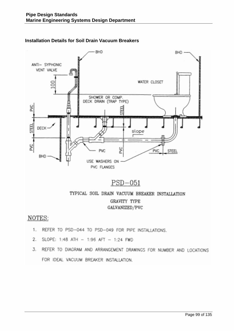
Installation Details for Soil Drain Vacuum Breakers
Page 100 of 135
Pipe Design Standards Marine Engineering Systems Design Department
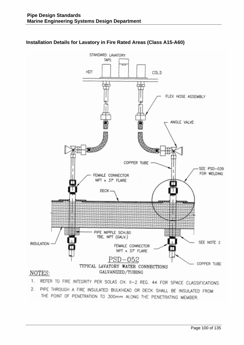
Installation Details for Lavatory in Fire Rated Areas (Class A15-A60)
Page 101 of 135
Pipe Design Standards Marine Engineering Systems Design Department
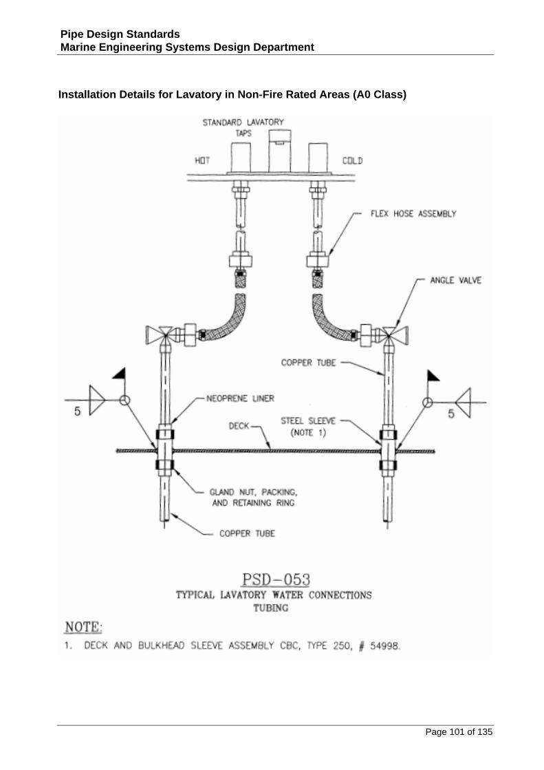
Installation Details for Lavatory in Non-Fire Rated Areas (A0 Class)
Page 102 of 135
Pipe Design Standards Marine Engineering Systems Design Department
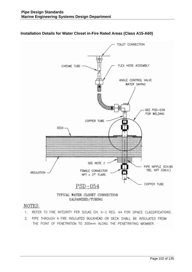
Installation Details for Water Closet in-Fire Rated Areas (Class A15-A60)
Page 103 of 135
Pipe Design Standards Marine Engineering Systems Design Department
Installation Details for Water Closet in Non-Fire Rated Areas (Class A0)
Page 104 of 135
Pipe Design Standards Marine Engineering Systems Design Department
Installation Details for Potable Water in Fire Rated Areas (Class A15-A60)
Page 105 of 135
Pipe Design Standards Marine Engineering Systems Design Department
Installation Detail for Sounding Pipe
Page 106 of 135
Pipe Design Standards Marine Engineering Systems Design Department
Fabrication Detail for International Shore Connection

Page 107 of 135
Pipe Design Standards Marine Engineering Systems Design Department
Pipe Supports
Page 108 of 135
Pipe Design Standards Marine Engineering Systems Design Department
Typical Installation Details for Pipe Supports
Page 109 of 135
Pipe Design Standards Marine Engineering Systems Design Department
Typical Installation Details for Pipe Supports
Page 110 of 135
Pipe Design Standards Marine Engineering Systems Design Department
Typical Installation Details for Pipe Supports
Page 111 of 135
Pipe Design Standards Marine Engineering Systems Design Department
Typical Installation Details for Pipe Supports
Page 112 of 135
Pipe Design Standards Marine Engineering Systems Design Department
Typical Installation Details for Pipe Supports
Page 113 of 135
Pipe Design Standards Marine Engineering Systems Design Department
Installation Details for Pipe Supports
Page 114 of 135
Pipe Design Standards Marine Engineering Systems Design Department
Typical Installation Details for Pipe Supports
Page 115 of 135
Pipe Design Standards Marine Engineering Systems Design Department
U-Bolt Installation Details and Notes
Page 116 of 135
Pipe Design Standards Marine Engineering Systems Design Department
U-Bolt Fabrication Standard
Page 117 of 135
Pipe Design Standards Marine Engineering Systems Design Department
U-Bolt Drilling Patterns
Page 118 of 135
Pipe Design Standards Marine Engineering Systems Design Department
U-Bolt Drilling Patterns
Page 119 of 135
Pipe Design Standards Marine Engineering Systems Design Department
Typical Installation Details for Pipe Hangers
Page 120 of 135
Pipe Design Standards Marine Engineering Systems Design Department
Installation Dimensions for Pipe Hangers
Page 121 of 135
Pipe Design Standards Marine Engineering Systems Design Department
Typical Installation Details for Pipe Hangers
Page 122 of 135
Pipe Design Standards Marine Engineering Systems Design Department
Installation Dimensions for Pipe Hangers
Page 123 of 135
Pipe Design Standards Marine Engineering Systems Design Department
Installation Details and Dimensions for J-Hangers
Page 124 of 135
Pipe Design Standards Marine Engineering Systems Design Department
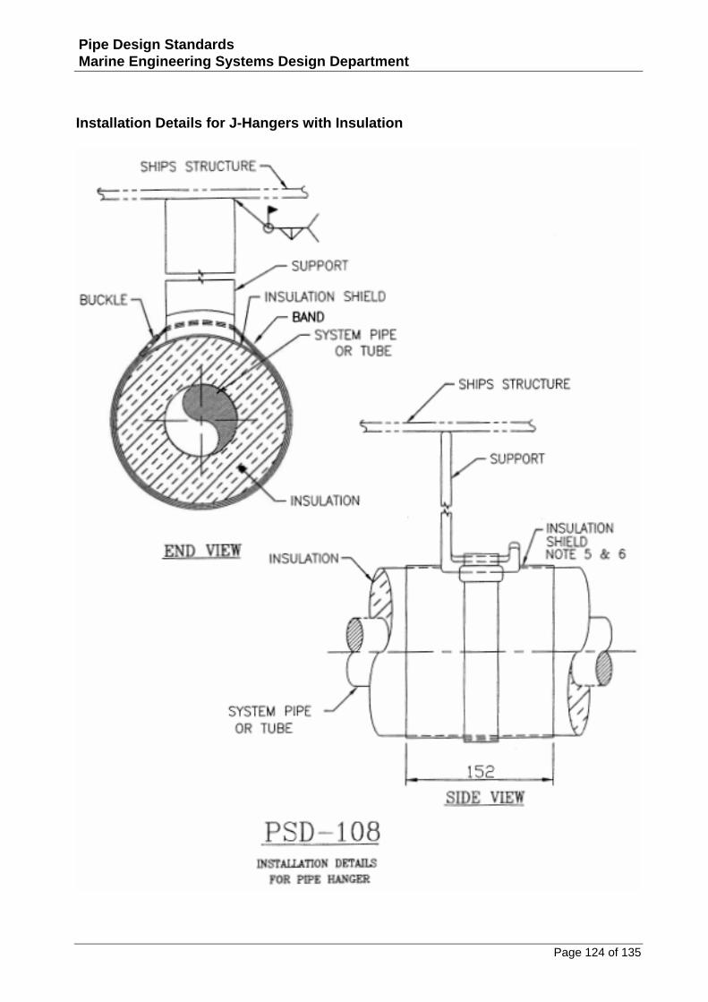
Installation Details for J-Hangers with Insulation
Page 125 of 135
Pipe Design Standards Marine Engineering Systems Design Department
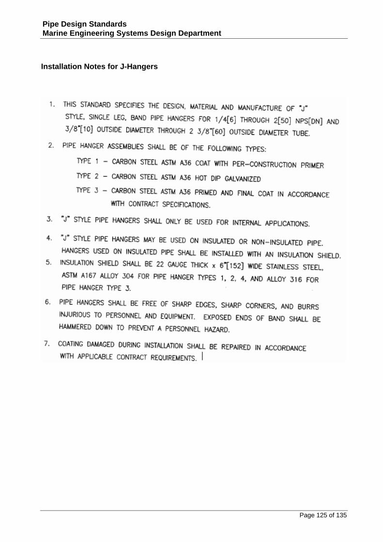
Installation Notes for J-Hangers
Page 126 of 135
Pipe Design Standards Marine Engineering Systems Design Department
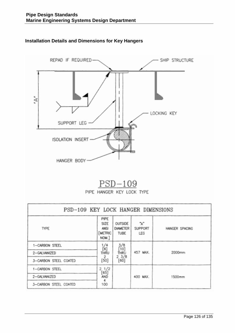
Installation Details and Dimensions for Key Hangers
Page 127 of 135
Pipe Design Standards Marine Engineering Systems Design Department
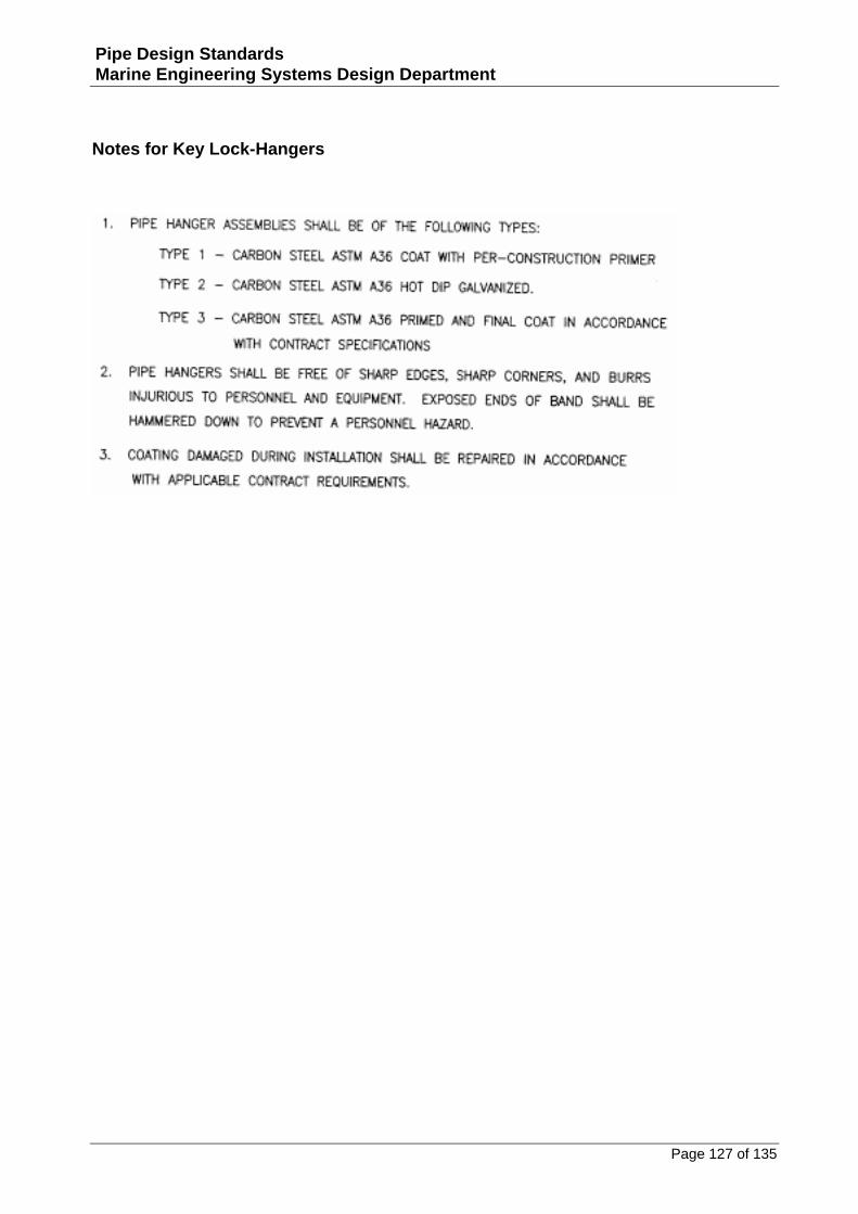
Notes for Key Lock-Hangers
Page 128 of 135
Pipe Design Standards Marine Engineering Systems Design Department
Installation Details and Spacing for Tube Supports
Page 129 of 135
Pipe Design Standards Marine Engineering Systems Design Department
Installation Details and Notes for Tube Supports
Page 130 of 135
Pipe Design Standards Marine Engineering Systems Design Department
Fabrication Details for Insulated Line Sizes 2-1/2” to 12”
Page 131 of 135
Pipe Design Standards Marine Engineering Systems Design Department
Installation Details for Insulated Line Sizes 2-1/2” to 12”
Page 132 of 135
Pipe Design Standards Marine Engineering Systems Design Department
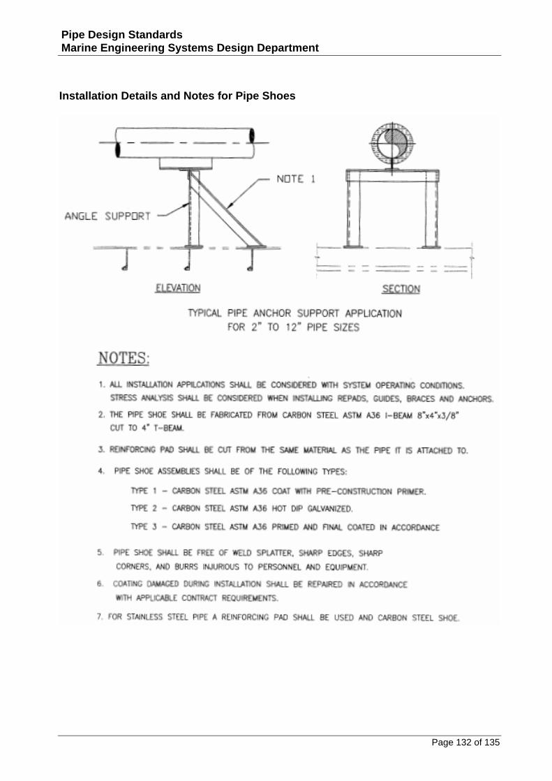
Installation Details and Notes for Pipe Shoes
Page 133 of 135
Pipe Design Standards Marine Engineering Systems Design Department
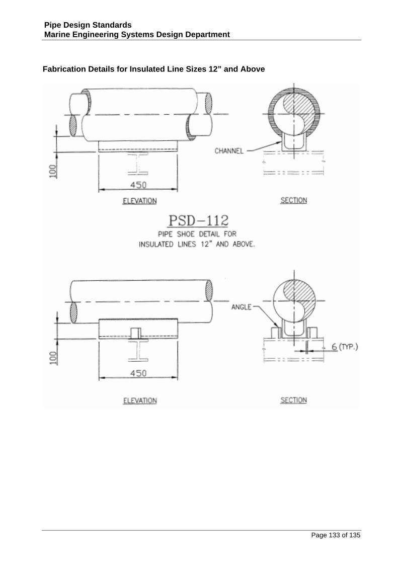
Fabrication Details for Insulated Line Sizes 12” and Above
Page 134 of 135
Pipe Design Standards Marine Engineering Systems Design Department
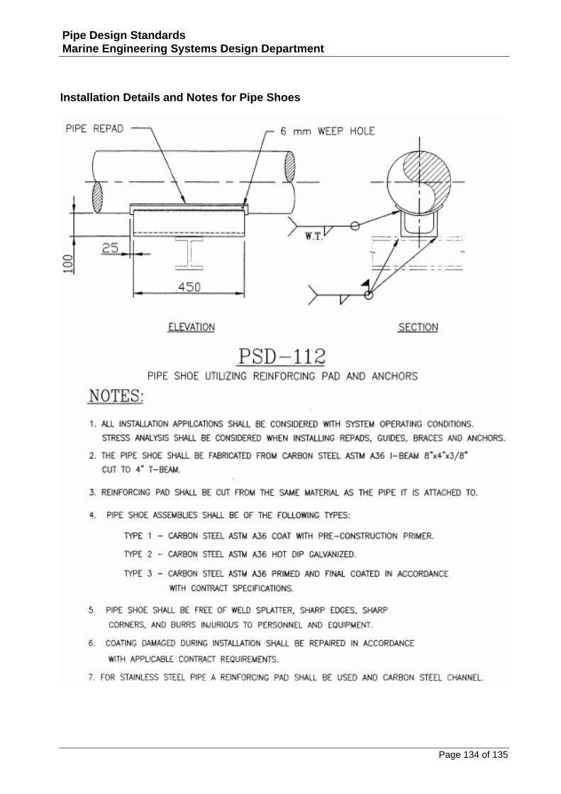
Installation Details and Notes for Pipe Shoes
Page 135 of 135
Pipe Design Standards Marine Engineering Systems Design Department
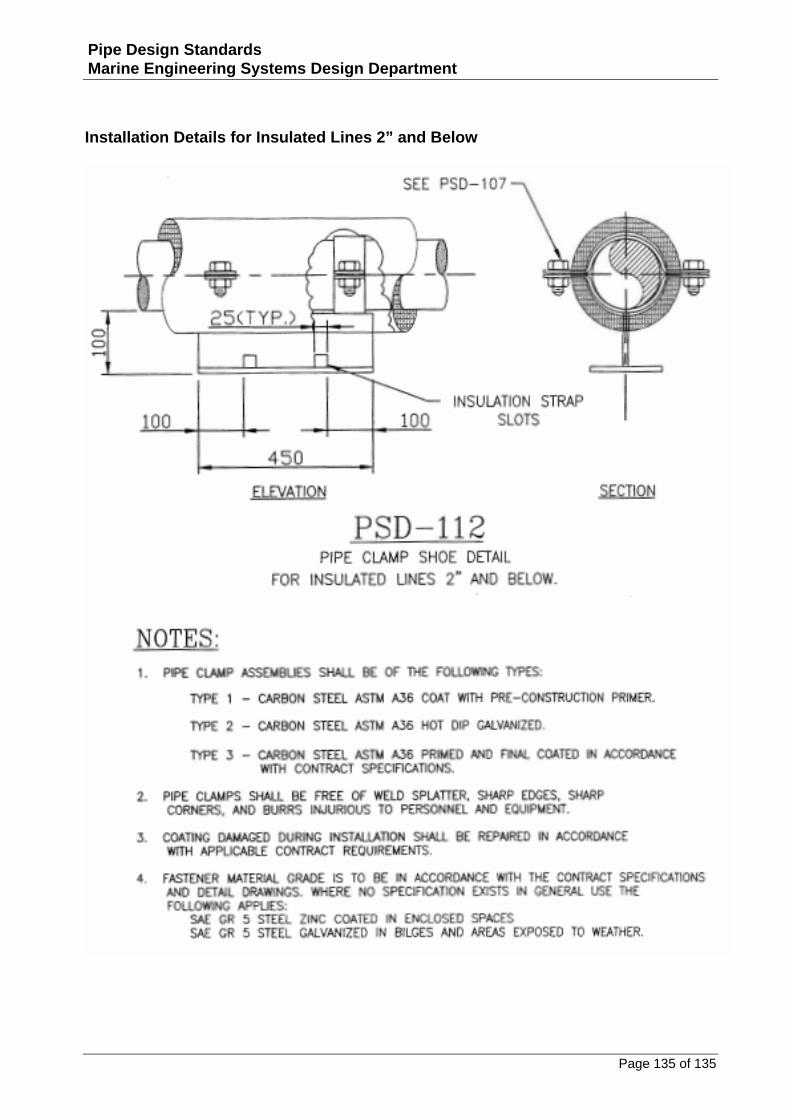
Installation Details for Insulated Lines 2” and Below