marine corps 10271a-10/1a operator's...
TRANSCRIPT
DISTRIBUTION STATEMENT C - Distribution authorized to U.S. Government agencies and their contractors. This publication is required for administration and operational purposes, as determined 16 August 1991. Other requests for this document shall be referred to either: Commander, U.S. Army Communications-Electronics Command and Fort Monmouth, ATTN: AMSEL-LC-LEO-E-ED-P, Fort Monmouth, NJ 07703-5000; or Commandant of the Marine Corps (ARD), Washington, DC 20380-0001.
ARMY TM 11-5855-306-10 MARINE CORPS 10271A-10/1A
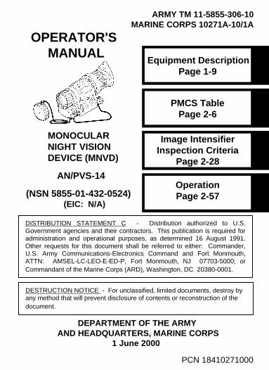
OPERATOR'S MANUAL
MONOCULAR NIGHT VISION DEVICE (MNVD)
AN/PVS-14
(NSN 5855-01-432-0524) (EIC: N/A)
PMCS Table Page 2-6
Image Intensifier Inspection Criteria
Page 2-28
Operation Page 2-57
Equipment Description Page 1-9
DEPARTMENT OF THE ARMYAND HEADQUARTERS, MARINE CORPS
1 June 2000
PCN 18410271000
DESTRUCTION NOTICE - For unclassified, limited documents, destroy by any method that will prevent disclosure of contents or reconstruction of the document.

a
Do not carry batteries in pockets containing metalobjects such as coins, keys, etc. Metal objectscan cause the batteries to short circuit andbecome very hot.
Toxic Material
The image intensifier’s phosphor screen contains toxic materials.
• If an image intensifier breaks, be extremelycareful to avoid inhaling the phosphor screenmaterial. Do not allow the material to comein contact with the mouth or open wounds onthe skin.
• If the phosphor screen material contacts yourskin, wash it off immediately with soap andwater.
• If you inhale/swallow any phosphor screenmaterial, drink a lot of water, induce vomiting,and seek medical attention as soon aspossible.
The IR source is a light that is invisible to theunaided eye for use during conditions of extremedarkness. However, the light from the IR sourcecan be detected by the enemy using night visiondevices.
WARNING
WARNING
WARNING

b
The monocular will not be turned off automaticallywhen flipped up. The monocular must be turnedoff by the power switch.
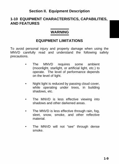
EQUIPMENT LIMITATIONS
To avoid personal injury and property damage when using theMNVD carefully read and understand the following safetyprecautions.
• The MNVD requires some ambient(moonlight, starlight, or artificial light, etc.) tooperate. The level of performance dependson the level of light.
• Night light is reduced by passing cloud cover,while operating under trees, in buildingshadows, etc.
• The MNVD is less effective viewing intoshadows and other darkened areas.
• The MNVD is less effective through rain, fog,sleet, snow, smoke, and other reflectivematerial.
• The MNVD will not “see” through densesmoke.
WARNING
WARNING

c/d blank
The compass illuminator can be seen by othersusing night vision devices.
Do not use contaminated eyecup or eyeguard.They must be replaced.
When installing the headmount over the protectivemask, be careful not to break the protective maskseal around your face.
FIRST AID
For first aid or artificial respiration, see FM 21-11, First Aidfor Soldiers.
WARNING
WARNING
WARNING

i/ii blank
TECHNICAL MANUAL DEPARTMENT OF THE ARMYNo. 11-5855-306-10* AND HEADQUARTERS,TECHNICAL MANUAL MARINE CORPSNo. 10271A-10/1A Washington, DC
1 June 2000
OPERATOR’S MANUALMONOCULAR NIGHT VISION DEVICE (MNVD)
AN/PVS-14(NSN 5855-01-432-0524)
(EIC: N/A)
REPORTING ERRORS AND RECOMMENDING IMPROVEMENTS
You can help improve this manual. If you find any mistakes or if youknow of a way to improve the procedures, please let us know. Mailyour letter or DA Form 2028 (Recommended Changes to Publicationsand Blank Forms) direct to: Commander, U.S. Army Communications-Electronics Command and Fort Monmouth, ATTN: AMSEL-LC-LEO-D-CS-CFO, Fort Monmouth, NJ 07703-5000. Marine Corps personnelsend NAVMC 10772 (Recommended Changes to Publications/-Logistics-Maintenance Data Coding) to: Commander Marine CorpsLogistics Base (Code 826) 814 Radford Blvd., Albany, GA 31704-1128.
*This manual supersedes TM 11-5855-306-10, dated1 December 1997 and all changes thereto.

iii
TABLE OF CONTENTS
Paragraph Title Page
CHAPTER 1 INTRODUCTION 1-1
Section I General Information 1-11-1 Scope 1-11-2 Maintenance Forms and Procedures 1-11-3 Corrosion Prevention and Control
(CPC)1-2
1-4 Destruction of Electronic Materiel toPrevent Enemy Use
1-2
1-5 Reporting Equipment ImprovementRecommendations (EIR)
1-3
1-6 Warranty Information 1-31-7 Nomenclature Cross-Reference List 1-31-8 List of Abbreviations and Acronyms 1-51-9 Glossary 1-6
Section II Equipment Description 1-9
1-10 Equipment Characteristics,Capabilities, and Features
1-9
1-11 Location and Description of MajorComponents
1-10
1-12 Equipment Data 1-16
Section III Principles of Operation 1-191-13 Mechanical Functions 1-191-14 Optical Functions 1-201-15 Electronic Circuit Function 1-20

iv
TABLE OF CONTENTS - Continued.
Paragraph Title Page
CHAPTER 2 OPERATING INSTRUCTIONS 2-1
Section I Description and Use of Operator’sControls and Indicators
2-1
2-1 Operator Controls and Indicators 2-1
Section II Preventive Maintenance Checks andServices (PMCS)
2-6
2-2 Preventive Maintenance Checks andServices Table
2-6
2-3 Resolution Check Using the TS-4348/UVTest Set
2-23
2-4 Inspection Criteria for Proper ImageIntensifier Operation
2-28
Section III Assembly and Preparation for Use 2-352-5 Unpacking 2-352-6 Installation of Batteries 2-362-7 Installation of Eyecup or Eyeguard 2-382-8 Installation of Demist Shield 2-382-9 Installation of Sacrificial Window 2-39
2-10 Installation of LIF 2-392-11 Installation and Adjustment of Headmount 2-412-12 Installation of Headmount/Helmet Mount
Adapter2-44

v
TABLE OF CONTENTS - Continued.
Paragraph Title Page
2-13 Installation of Helmet Mount to Helmet 2-452-14 Installation of Headmount with
Protective Mask2-50
2-15 Installation of Weapon Mount 2-512-16 Installation of Compass 2-532-17 Installation of 3X Magnifier 2-55
Section IV Operating Procedures 2-57
2-18 Hand-Held Operation 2-572-19 Head Mounted Operation 2-582-20 Helmet Mounted Operation 2-602-21 Weapon Mounted Operation 2-642-22 IR Source Operations 2-652-23 Operation with Compass 2-652-24 Operation with 3X Magnifier 2-682-25 Operation with Gain Control 2-682-26 Preparation for Storage 2-69
Section V Operation Under Unusual Conditions 2-702-27 Operation in Dusty or Sandy Areas 2-702-28 Operation in Rainy or Humid Conditions 2-712-29 Operation in Salt Water Areas 2-712-30 Operation in Nuclear, Biological and
Chemical (NBC) Environments2-72
2-31 Operation in Laser ThreatEnvironments
2-72

vi
TABLE OF CONTENTS - Continued.
Paragraph Title Page
CHAPTER 3 MAINTENANCE INSTRUCTIONS 3-1
Section I Lubrication Instructions 3-1
Section II Troubleshooting Procedures 3-13-1 Troubleshooting 3-1
Section III Operator’s Maintenance Procedures 3-73-2 Cleaning the MNVD 3-73-3 Headmount Maintenance 3-73-4 Neck Cord Maintenance 3-10
APPENDIX A REFERENCES A-1
APPENDIX B COMPONENTS OF END ITEM (COEI)AND BASIC ISSUE ITEMS (BII) LISTS
B-1
APPENDIX C ADDITIONAL AUTHORIZATION LIST(AAL)
C-1
APPENDIX D EXPENDABLE AND DURABLE ITEMSLIST
D-1
SUBJECT INDEX Index

vii /viii blank
HOW TO USE THIS MANUAL
• Usage
You must familiarize yourself with the entire manual beforeoperating the equipment. Read and follow all warning notices.
• Manual Overview
The table of contents includes the paragraph number, paragraphtitle, and page number for each chapter. An index providesadditional references to the subject contents.
• Speci al Features
A locator is provided on the right hand border of the front cover.This gives the location of the information most frequently used. Tofind the topic Operation, open the manual to the correct page byusing the black tab on the side of the manual that lines up with thetopic Operation.

1-1
CHAPTER 1INTRODUCTION
Section I. General Information
1-1 SCOPE
This manual provides operation and maintenance instructions forthe Monocular Night Vision Device (MNVD), AN/PVS-14 herein-after referred to as the MNVD. The MNVD is a self-contained nightvision device that enables improved night vision using ambientlight from the night sky (moon, stars, skyglow, etc.).
1-2 MAINTENANCE FORMS AND PROCEDURES
Department of the Army forms and procedures used for equipmentmaintenance will be those prescribed in DA Pam 738-750, ascontained in Maintenance Management Update.
Refer to the latest issue of DA Pam 25-30 to determine whetherthere are new editions, changes or additional publications or formspertaining to this equipment.
Marine Corps personnel refer to the on-line MCPDS Marine CorpsPublication Distribution System.
Marine Corps Ground Record Procedures. Marine Corpspersonnel refer to TM 4700-15/1 for disposition of forms andrecords required for Marine Corps equipment.

1-2
1-3 CORROSION PREVENTION AND CONTROL (CPC)
Corrosion prevention and control of Army materiel is a continuingconcern. It is important that any problems with this equipment bereported so that the problem can be corrected and improvementsmade to prevent the problem in future equipment.
While corrosion is typically associated with rusting metal, it canalso include deterioration of other materials such as contacts,injection-molded plastic, and foam inserts in the case. Unusualcracking, softening, swelling, or breaking of these other materialsmay be a corrosion problem.
If a corrosion problem is identified, report it using Standard Form368, Product Quality Deficiency Report. Use keywords such as“corrosion,” “rust,” “deterioration,” or “cracking” to ensure that theinformation is identified as a CPC problem. Submit the form to theaddress specified in DA Pam 738-750.
1-4 DESTRUCTION OF ELECTRONIC MATERIEL TOPREVENT ENEMY USE
For procedures to destroy this equipment to prevent its use by theenemy, refer to TM 750-244-2, Procedures for Destruction ofElectronic Materiel to Prevent Enemy Use (Electronics Command).Marine users , render the MNVD inoperable by smashing,scattering or burying disassembled pieces, burning, or destroyingby weapons fire.

1-3
1-5 REPORTING EQUIPMENT IMPROVEMENT RECOM-MENDATIONS (EIR)
If your equipment needs improvement, let us know. Send us anEIR. You, the user, are the only one who can tell us what youdon’t like about the design. Put it on an SF 368, Product QualityDeficiency Report. Mail it to Commander, U.S. ArmyCommunications-Electronics Command and Fort Monmouth,ATTN: AMSEL-LC-LEO-D-CS-CFO, Fort Monmouth, New Jersey07703-5000. We’ll send you a reply.
Marine Corps personnel are encouraged to submit SF 368 inaccordance with MCO 4855.10 (Quality Deficiency Report).
1-6 WARRANTY INFORMATION
Some MNVD systems are under warranty. The warrantyexpiration date label is affixed to the front (objective lens end) ofthe monocular on the opposite side from the power switch. Reportall defects in material or workmanship to your maintainer, who willtake the appropriate action.
1-7 NOMENCLATURE CROSS-REFERENCE LIST
Table 1-1 provides a cross reference of common names andofficial terms. Except in the Appendices, the common names willbe used. The official names are used in the Appendices becausethey reflect the provisioning nomenclature.

1-4
Table 1-1. Nomenclature Cross-Reference List.
COMMON NAME OFFICIAL NOMENCLATURE
Batteries Battery, NonrechargeableBattery Cartridge Cover, Battery RetainerCarrying Case Case, Infrared EquipmentCarrying Case Strap StrappingCompass Compass AssemblyDemist Shield Lens, Infrared ReceiverEyeguard Eyeguard, OpticalEyepiece Lens Cap Cap, Protective, DustHeadmount Headset AssemblyHeadmount/Helmet MountAdapter
Adapter, Headset
Helmet Mount Mount, ViewerLIF Filter, Infrared LightMedium Browpad Browpad Assy, MediumMonocular Monocular AssyNeck Cord Cord, FibrousObjective Lens Cap Cap, Protective, DustSacrificial Window Window, SacrificialShipping and Storage Case Case, Shipping/StorageTethering Cord Clip, RetainingThick Browpad Browpad Assy, ThickThin Browpad Browpad Assy, Thin3X Magnifier Magnifier Lens AssemblyWeapon Mount Bracket, Mounting

1-5
1-8 LIST OF ABBREVIATIONS AND ACRONYMS
AAL Additional Authorization ListBII Basic Issue ItemsCAGEC Commercial and Government Entity Codecm CentimetersCOEI Components of End ItemCPC Corrosion Prevention and ControlCTA Common Table of AllowancesDA Department of the ArmyEIC End Item CodeEIR Equipment Improvement RecommendationFM Field ManualHrs HoursIR InfraredJTA Joint Table of Allowanceslbs PoundsLED Light Emitting DiodeLIF Light Interference FilterMCPDS Marine Corp Publication Distribution SystemMNVD Monocular Night Vision DeviceMTOE Modified Table of Organization and EquipmentN/A Not ApplicableNBC Nuclear, Biological, and ChemicalNSN National Stock NumberPam PamphletPASGT Personal Armor System Ground TroopsPMCS Preventive Maintenance Checks and ServicesQty QuantityRecm RecommendedRqr RequiredSF Standard FormTAMMS The Army Maintenance Management SystemTDA Table of Distribution and AllowancesTM Technical ManualTOE Table of Organization and EquipmentU/M Unit of MeasureVdc Volts, direct current
1-6
1-9 GLOSSARY
BLACK SPOTS. These are cosmetic blemishes in the imageintensifier of the MNVD or dirt or debris between the lenses.
BRIGHT SPOTS. These defects can appear in the image area ofthe MNVD. This condition is caused by a flaw in the film on themicrochannel plate. A bright spot is a small, nonuniform, brightarea that may flicker or appear constant. Bright spots usually goaway when the light is blocked out and are cosmetic blemishesthat are signal induced.
BROWPADS. Three hook-and-pile browpads are provided toadjust the headmount to fit different head sizes. The thin browpad(large head) comes attached to the headmount and the thick (smallhead) or medium browpads are stored in the carrying case.
CAUTION. Condition, practices, or procedures that must beobserved to avoid damage to equipment, destruction of equipment,or a long-term health hazard.
CHICKEN WIRE. An irregular pattern of dark thin lines in thefield-of-view either throughout the image area or in parts of theimage area. Under the worst case condition, these lines will formhexagonal or square-wave shaped lines.
DARK (OR DARK AREA). A place in which there is very littlelight. It does not mean total darkness. Generally, this meansconditions similar to a quarter-moon or starlit night.
DARK-ADAPTED. Having ones eye adjusted to the monocular’soutput under low light conditions.
DIOPTER. A unit of measure used to define eye correction.Adjustments to the diopter adjustment will provide a clearer imagein each eye.

1-7
EDGE GLOW. This is a defect in the image area of themonocular. Edge glow is a bright area (sometimes sparkling) inthe outer portion of the viewing area.
EMISSION POINT. A steady or fluctuating pinpoint of bright lightin the image area and does not go away when all light is blockedfrom the objective lens of the monocular. The position of anemission point within the image area of the monocular does notmove. An emission point should not be confused with a point lightsource in the distance.
FIXED-PATTERN NOISE. This is a cosmetic blemish in theimage area characterized by a faint hexagonal (honeycomb)pattern throughout the viewing area that most often occurs at highlight levels or when viewing very bright lights. Fixed-pattern noiseis inherent in the structure of the fiber optics and can be seen inevery image intensifier if the light level is high enough.
FLASHING. This is a defect in the image area of the monocular.The image appears to flicker or flash.
FLICKERING. See “flashing.”
GAIN. This is the number of times a night vision device amplifieslight input.
IMAGE INTENSIFIER. An electro-optical device that detects andamplifies ambient light to produce a visual image.
INFINITY FOCUS. Adjustment of the objective lens so that adistant object, such as a star or the point light on a distant tower,forms the sharpest image.
INTERMITTENT OPERATION. This is a defect in the image areaof the monocular. See “flashing”.

1-8
IR SOURCE. This is an IR Light Emitting Diode (LED). Whenturned on, the IR source provides additional illumination toenhance existing light conditions used only for performing nearbytasks.
LIGHT INTERFERENCE FILTER (LIF). This is a light protectionfilter for the monocular. Use of this filter will result in a slightreduction in system gain.
MICROCHANNEL PLATE. A current-multiplying optical disk thatintensifies the electron image produced by the photocathode.
NOTE. Essential information of special importance, interest, oraid in job performance.
PHOTOCATHODE. The input optic of an image intensifier thatabsorbs light energy and in turn releases electrical energy in theform of an electron image.
SCINTILLATION. A faint, random, sparkling effect throughout theimage area. Scintillation is a normal characteristic of the imageintensifier and should not be confused with emission points.Scintillation is more pronounced under low light conditions. Alsocalled “video noise”.
SHADING. The viewed image should be a full circle. If shading ispresent, you will not see a fully circular image. Shading isindicative of a dying photocathode and is caused by a defectivevacuum seal of the image intensifier. Shading is very dark and youcannot see an image through it.
WARNING. Conditions, practices, or procedures that must beobserved to avoid personal injury or loss of life.
1-9
Section II. Equipment Description
1-10 EQUIPMENT CHARACTERISTICS, CAPABILITIES, AND FEATURES
EQUIPMENT LIMITATIONS To avoid personal injury and property damage when using the MNVD carefully read and understand the following safety precautions.
• The MNVD requires some ambient
(moonlight, starlight, or artificial light, etc.) to operate. The level of performance depends on the level of light.
• Night light is reduced by passing cloud cover,
while operating under trees, in building shadows, etc.
• The MNVD is less effective viewing into
shadows and other darkened areas. • The MNVD is less effective through rain, fog,
sleet, snow, smoke, and other reflective material.
• The MNVD will not “see” through dense
smoke.
WARNING

1-10
• The MNVD is a precision optical instrumentand must be handled carefully at all times toprevent damage.
• Be careful when leaving the helmet mount inthe flipped up position or removing the helmetmount from the helmet, damage can result.
The MNVD is a hand-held, headmounted, helmet mounted, orweapon mounted night vision system that enables walking,weapon firing, short-range surveillance, map reading, vehiclemaintenance, and administering first aid in both moonlight andstarlight. Each unit allows for vertical adjustment (by using headstrap), fore-and-aft adjustment, objective lens focus and eyepiecefocus. The monocular is also equipped with an IR source, a low-battery indicator and a gain control.
1-11 LOCATION AND DESCRIPTION OF MAJOR COM-PONENTS
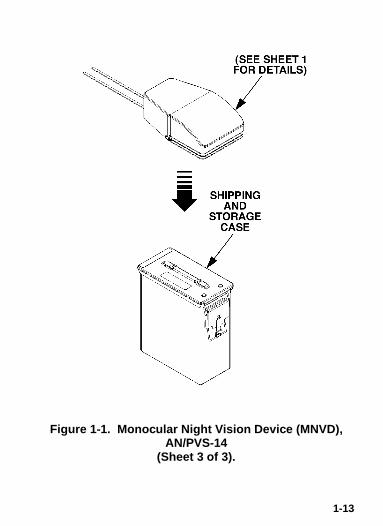
The MNVD includes the items shown in Figure 1-1. The majorcomponents are the headmount, helmet mount, monocular,carrying case, and the shipping and storage case.
a. Monocular . The monocular (see Figure 1-2) consists ofvarious components such as an objective lens, an image intensifier(not shown), an eyepiece lens and a battery cartridge.
CAUTION

1-11
Figure 1-1. Monocular Night Vision Device (MNVD),AN/PVS-14
(Sheet 1 of 3).

1-12
Figure 1-1. Monocular Night Vision Device (MNVD),AN/PVS-14
(Sheet 2 of 3).
1-13
Figure 1-1. Monocular Night Vision Device (MNVD),AN/PVS-14
(Sheet 3 of 3).

1-14
Figure 1-2. Monocular Night Vision Device.
The monocular also uses the accessories listed below:
Demist Shield – The demist shield (Figure 1-1) is used toprevent the eyepiece lenses from becoming fogged.
LIF – The LIF (Figure 1-1) is to be used at all times. Forreplacing the filter the container is also the wrench. Thecontainer/wrench is used to remove and replace the LIFfrom the objective lens.
Sacrificial Window – A replaceable sacrificial window(Figure 1-1) is supplied to protect the objective lensduring operation in adverse conditions.

1-15
Compass – The compass (Figure 1-1) enables theoperator to see azimuth readings in the monocular.
Tethering Cord – The tethering cord (Figure 1-1) enablesthe user to attach the compass or 3X magnifier to abutton hole or belt loop to guard against dropping orlosing these items.
3X Magnifier – (Additional Authorized Item) The 3Xmagnifier (Figure 1-1) is a lens assembly which can beadded to the monocular to extend the operator’sobservation ranges.
b. Headmount. The headmount (Figure 1-1) secures themonocular to the operator’s head for night viewing and providesfreehand support for use with a weapon, protective mask or otherpurposes. It is adjustable and cushioned. The thin browpad usedfor large heads, comes attached to the headmount; the thick andmedium browpads, used for smaller heads are stored in thecarrying case.
c. Helmet Mount. This item (Figure 1-1), secures themonocular to the Personal Armor System Ground Troops (PASGT)helmet allowing freehand support for use with a weapon, protectivemask and/or other purposes. The new helmet mount is made of aruggedized metal. The old one is made of plastic.
d. Headmount/Helmet Mount Adapter. This item (Figure 1-1)is attached to the monocular to allow its use with the headmount orhelmet mount. It allows mounting in front of the left or right eye.
e. Weapon Mount. The weapon mount (Figure 1-1) adapts themonocular to the receiver rail as configured for the modularweapon system kit.

1-16
f. Carrying Case. The carrying case (Figure 1-1) is providedfor transportation and protection of the monocular, headmount,batteries and accessories. Two slide keepers are provided for beltattachment and three D-rings for shoulder and leg strapattachment. A carrying case strap is also provided which can beattached to the two D-rings on the back of the carrying case.
g. Shipping and Storage Case. The MNVD is supplied in ashipping and storage case (Figure 1-1).
1-12 EQUIPMENT DATA
The following tables provide information pertaining to theoperational, electrical, mechanical, optical, and environmentalcharacteristics for the monocular.

1-17
Table 1-2. Operator Adjustment Limits.
ITEM LIMITS
Diopter Focus +2 to –6 dioptersObjective Focus 25 cm to infinity
Table 1-3. Electrical Data.
ITEM DATA
Power Source Battery (1.5 Vdc max ea.)Battery Requirements 2 AA Alkaline or
2 AA 1.5 Vdc Lithium L91
Table 1-4. Mechanical Data.
ITEM CHARACTERISTICS
Shipping and Storage Case Size: Approx.14” X 9.5” X 8”Weight: 2.4 lbs.
Carrying CaseMonocular (see Note)
Size: Approx. 14” X 8”Weight: 14 ounces
NOTE: Weight of the monocular does not include accessories.

1-18
Table 1-5. Optical Data.
ITEM DATA
Magnification 1.0X(3X with 3X magnifier)
Field-of-View 40°(13° with 3X magnifier)
Diopter Focus +2 to –6 dioptersObjective Focus 25cm (9.8”) to infinity
Table 1-6. Environmental Data.
ITEM DATA
Monocular Operating Temperature -51°C to +49°CMonocular Storage Temperature -51°C to +85°CIllumination Required Overcast starlight to moonlight

1-19
Section III. Principles of Operation
1-13 MECHANICAL FUNCTIONS
The mechanical functions of the MNVD allow for differences in thephysical features of individual operators and provide for operatingthe system. These functions include the power switch, eye reliefadjustment, diopter adjustment, gain control, and objective focus.The mechanical controls are identified in Figure 1-3.
Figure 1-3. Mechanical Functions for the MNVD.

1-20
1-14 OPTICAL FUNCTIONS
The optical functions include an objective lens, image intensifierand eyepiece lens (Figure 1-4). The objective lens collects lightreflected from the night scene by the moon, stars, or night sky,inverts the image and focuses that image on the image intensifier.The image intensifier converts the captured light into a visibleimage and reinverts the image which can then be viewed throughthe eyepiece lens.
Figure 1-4. Optical Function Diagram.
1-15 ELECTRONIC CIRCUIT FUNCTION
The electronic circuit regulates the direct current voltage from thebatteries to the image intensifier and IR source as required. It alsomonitors the output voltage of the batteries and turns on a low-battery indicator when the available battery voltage is 1.9 – 2.1Vdc.

1-21/22 blank
a. Power So urce. The electronic circuit is powered by twobatteries.
b. High Li ght Cut-Off . The monocular will automatically cut offafter 70 ±30 seconds of operation in daylight or bright room light.Individual bright lights (headlights, flashlights, or otherconcentrated light sources) will not actuate the high light detectorlocated on the front of the monocular. To turn the monocular backON, turn the power switch to RESET/OFF position and then to ONagain.

2-1
CHAPTER 2OPERATING INSTRUCTIONS
Section I. Description and Use of Operator’sControls and Indicators
NOTE
The MNVD is a precision electro-opticalinstrument, so handle it carefully. If the equipmentfails to operate, refer to the TroubleshootingProcedures in Chapter 3, Section II.
2-1 OPERATOR CONTROLS AND INDICATORS
The MNVD is designed to adjust for different users and corrects formost differences in eyesight. The controls and indicators for theMNVD are shown in Figures 1-3 and 2-1, which are described inTable 2-1.

2-2
Figure 2-1. Monocular Controls and Indicators.

2-3
Table 2-1. Monocular Controls and Indicators.
CONTROLS ANDINDICATORS
FUNCTIONS
Power Switch Controls monocular and IR source,ON or OFF.
RESET/OFF
Same as system OFF.Also resets monocularafter high light cut-off.
ON Monocular activated.
IR/PULL Turn the knob clockwiseto momentarily activatethe IR source. Pull andturn the knob clockwisefrom the ON position tocontinuously activate theIR source.
Do not use excessive force to place the powerswitch into the momentary IR position.
CAUTION

2-4
Table 2-1. Monocular Controls and Indicators -Continued.
CONTROLS ANDINDICATORS
FUNCTIONS
Low Battery Indicator When blinking it indicates a lowbattery condition with less than 30minutes of battery life remaining. It isvisible through the eyepiece justoutside the intensified field-of-view.
IR Source On Indicator When illuminated it indicates that theIR source is ON. It is visible throughthe eyepiece just outside theintensified field-of-view.
Gain Control Adjusts the system gain from aminimum value of approximately 25to a maximum value greater than3,000.
Objective Focus Focuses objective lens. Adjusts forsharpest image of viewed object.
Diopter Adjustment Focuses eyepiece lens for usewithout the need for glasses. Adjustfor sharpest image of intensifierscreen.
Eye Relief Adjustment Adjusts the distance between youreye and the monocular.

2-5
Table 2-1. Monocular Controls and Indicator -Continued.
CONTROLS ANDINDICATORS
FUNCTIONS
Latch Latch used for separation ofmonocular from head-mount/helmet mount adapter.
Battery Polarity Indicators This feature, molded into thebattery cartridge, shows theproper orientation of thebatteries. Some versions havea bubble molded into the top ofthe battery cartridge, to showthe + for proper orientation.

2-6
Section II. Preventive Maintenance Checks andServices (PMCS)
2-2 PREVENTIVE MAINTENANCE CHECKS ANDSERVICES TABLE
NOTEThe unit maintenance tracks the system for whenthe 180 day service is due or any maintenancethat is performed by either hard copy orautomated. If using an automated system such asSAMS or ULLS, use the equivalent electronicform, to track using the same procedure as for thehard copy DA Form 2404, 2407 or DD Form 314etc.
a. General. To ensure the readiness of the MNVD, perform thepreventive maintenance procedures in accordance with Table 2-2,prior to each mission. Preventive maintenance procedures includeinspection, cleaning, and performance of the checkout procedures.
b. Warnings and Cautions. Always observe the WARNINGSand CAUTIONS appearing in the table. Warnings and cautionsappear before applicable procedures. You must observe thewarnings and cautions to prevent serious injury to yourself andothers, or to prevent your equipment from being damaged.

2-7
c. Explanation of Table Entries. (1) Item Number Column. Numbers in this column are for reference. When completing Equipment Inspection and Maintenance Worksheet, include the item number for the check/service indicating a fault. Item numbers also appear in the order that you must do checks and services for the intervals listed. (2) Interval Column. This column tells you when you must do the procedure in the procedure column. BEFORE procedures must be done before you operate or use the equipment for its intended mission. DURING procedures must be done during the time you are operating or using the equipment for its intended mission. AFTER procedures must be done immediately after you have operated or used the equipment. (3) Location, Check/Service Column. This column provides the location and the item to be checked or serviced. The item location is underlined. (4) Procedure Column. This column gives the procedure you must do to check or service the item listed in the Check/Service column to know if the equipment is ready or available for its intended mission or operation. You must do the procedure at the time stated in the interval column. (5) Not Fully Mission Capable If: Column. Information in this column tells you what faults will keep your equipment from being capable of performing its primary mission. If you make check and service procedures that show faults listed in this column, do not operate the equipment. Follow standard operating procedures for maintaining the equipment or reporting equipment failure.
2-8
NOTE
Damaged accessory items (sacrificial window,demist shield, compass) do not cause the entireend item to be “not fully mission capable".However, the damaged item should be replacedas soon as practical to restore full capability of thesystem.
d. Other Table Entries. Be sure to observe all specialinformation and notes that appear in your table.

2-9
Not FullyMission
Capable If:
Fault not corrected.
Scratches or heavy scratches that hinder vision with mon- ocular turned ON, or if cracks are present.
Procedure
Open carrying case, inventoryitems and check for:
• Previously recorded faults on maintenance records, DA Form 2404.
Inspect all lenses (objective, eyepiece, IR lens and high light cut-off window) for dirt, fingerprint residue, chips, or cracks. If necessary, clean and dry lenses with water and lens tissue.
Location
Check/Service
MaintenanceForms andRecords
MONOCULAR
Optical Surfaces
Interval
Before
Before/After
Table 2-2. Preventive Maintenance Checks and Services for the MNVD.
ItemNo.
1.
2.

2-10
Not FullyMission
Capable If:
Cracks or dam- age in the bat- tery housing.
Cartridge is missing, contacts damaged, or corroded, o-ring is missing.
Procedure
Inspect external surfaces for cracks or damage. Scratches, cracks, and gouges are OK if operation is not affected.
Inspect battery compartment. Check to make sure battery cartridge is present. Remove battery cartridge and inspect for moisture, cracks, corroded or defective spring contacts, and o-ring present in cartridge.
Location
Check/Service
Battery Cartridge/ Housing
Interval
Before/After
Table 2-2. Preventive Maintenance Checks and Services for the MNVD- Continued.
ItemNo.
3.

2-11
Not FullyMission
Capable If:
Power switch has no definite stopping points or knob is bro- ken or missing.
IR source does not work.
If damaged, refer to higher level of maintenance.
Procedure
Remove any batteries and turn the power switch from RESET/OFF to ON to IR/PULL. Each position should have a definite stopping point. Inspect for broken or missing knob.
Install batteries per paragraph 2-6. and check IR source (and momentary IR source, if so equipped) functions by following the operating instructions in paragraph 2-22.
Check the high light cut-off with day- light or bright room light (not fluo- rescent light) by placing the lens cap on the objective lens. Turn mon- ocular ON and observe that the system cuts OFF within 70 ±30 seconds.
Location
Check/Service
Battery Cartridge/ Housing Cont.
Interval
Before/After
Table 2-2. Preventive Maintenance Checks and Services for the MNVD- Continued.
ItemNo.
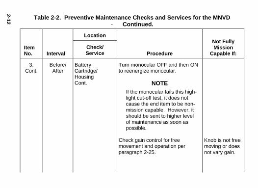
3.Cont.
2-12
Not FullyMission
Capable If:
Knob is not free moving or does not vary gain.
Procedure
Turn monocular OFF and then ON to reenergize monocular.
NOTE If the monocular fails this high- light cut-off test, it does not cause the end item to be non- mission capable. However, it should be sent to higher level of maintenance as soon as possible.
Check gain control for free movement and operation per paragraph 2-25.
Location
Check/Service
Battery Cartridge/ Housing Cont.
Interval
Before/After
Table 2-2. Preventive Maintenance Checks and Services for the MNVD- Continued.
ItemNo.
3.Cont.

2-13
Not FullyMission
Capable If:
Cracks or damage in the monocular.
Binding, not moving freely or too loose.
Chips and cracks are permitted on the eyecup retain- ing rings as long as they do not interfere with in- stallation of eyecup.
Procedure
Inspect for cracks or damage. Scratches, cracks, chips and gouges are OK if operation is not affected.
Rotate diopter adjustment to make sure the eyepiece lens moves freely and is not loose. Range is approximately ½ turn.
Inspect for dirt, dust, cracked or torn eyecup. Inspect for bent, broken, or improperly fitting eyepiece lens. If necessary, clean with water.
Location
Check/Service
Monocular
Eyepiece Lens
Eyecup
Interval
Before/After
Before/After
Before/After
Table 2-2. Preventive Maintenance Checks and Services for the MNVD- Continued.
ItemNo.
4.
5.
6.

2-14
Not FullyMission
Capable If:
Chips and cracks are permitted on the eyeguard retain- ing rings as long as they do not interfere with in- stallation of eyeguard.
Focus ring is binding or not able to move.
Procedure
Inspect for dirt, dust, cracked or torn eyeguard. Inspect for bent, broken, or improperly fitting eyeguard. If necessary, clean with water.
Rotate focus ring to ensure free movement (range is approximately 1/3 turn). Check objective lens for chips, cracks and dents.
Location
Check/Service
Eyeguard
Objective Lens
Interval
Before/After
Before/After
Table 2-2. Preventive Maintenance Checks and Services for the MNVD- Continued.
ItemNo.
7.
8.

2-15
Not FullyMission
Capable If:
Chips, cracks, or dents prevent full field-of-view, installation of LIF or the ability to focus.
Cracked or loose.
Damaged.
Procedure
Check the infinity focus locking ring for tightness. Check for cracks.
Inspect for cracked, torn, or missing objective lens cap. Inspect neck cord for cut, damage, or loose ends. Re-tie ends if necessary.
Location
Check/Service
Objective Lens Cont.
Neck Cord and Objective Lens Cap
Interval
Before/After
Before/After
Table 2-2. Preventive Maintenance Checks and Services for the MNVD- Continued.
ItemNo.
8.Cont.
9.

2-16
Not FullyMission
Capable If:
Flickering, flashing, edge glow, or shading is observed.
Procedure
NOTE Operator may use the TS-4348/UV to check resolution (paragraph 2-3).
Refer to paragraph 2-4 to inspect for operational defects.
NOTE
If any of the following items are damaged it does not cause the entire end item to be “not fully mission capable”. However, the damaged item should be re- placed as soon as practical to restore full capability of the system.
Location
Check/Service
Viewed Image
Interval
Before/After
Table 2-2. Preventive Maintenance Checks and Services for the MNVD- Continued.
ItemNo.
10.

2-17
Not FullyMission
Capable If:
Damage causes straps or pads to be unservice- able.
Damaged, latch won’t lock or is too loose.
Binding, damaged or non-operational slide mechanism.
Procedure
Inspect for cuts, tears, fraying, holes, cracks, or defective fasteners.
Inspect for dirt, dust, or corrosion. Insert monocular latch into socket to verify secure attachment of monocular to headmount. If necessary, clean socket with water.
Press the eye relief adjustment and check for free motion. Inspect for damage.
Location
Check/Service
HEADMOUNT
Straps/Pads
Socket
Eye Relief Adjustment
Interval
Before/After
Before/After
Before/After
Table 2-2. Preventive Maintenance Checks and Services for the MNVD- Continued.
ItemNo.
11.
12.
13.

2-18
Not FullyMission
Capable If:
Damage causes straps to be unserviceable.
Damaged, latch won’t lock or is too loose.
Binding, damaged or non-operational slide mechanism.
Procedure
Inspect for cuts, tears, fraying, holes, cracks, or defective fasteners.
Inspect for dirt, dust, or corrosion. Insert monocular latch into socket to verify secure attachment of monocular to helmet mount. If necessary, clean socket with water.
Press the 2 side buttons on plastic mount or depress side lever on metal mount and check for free motion. Inspect for damage.
Location
Check/Service
HELMET MOUNT
Straps
Socket
Fore-and-Aft Adjustment
Interval
Before/After
Before/After
Before/After
Table 2-2. Preventive Maintenance Checks and Services for the MNVD- Continued.
ItemNo.
14.
15.
16.

2-19
Not FullyMission
Capable If:
Damaged, will not latch securely.
Damaged, will not mount to monocular or will not mount to rail.
Procedure
Inspect for dirt, dust or corrosion. Insert into headmount or helmet mount socket to verify secure attachment.
Inspect for dust, dirt or corrosion.
Location
Check/Service
MOUNTINGADAPTERS
Headmount/ Helmet Mount Adapter
Weapon Mount
Interval
Before/After
Before/After
Table 2-2. Preventive Maintenance Checks and Services for the MNVD- Continued.
ItemNo.
17.
18.

2-20
Not FullyMission
Capable If:
Damage or scratches hinder vision with monocular on.
Procedure
CAUTION
The coating on the demistshield can be damaged ifcleaned while wet or if cleanedwith wet lens paper. Clean onlywhen the demist shield is dryand only with dry paper.
Inspect for dirt, dust, scratches or damage. If necessary, clean when shield is dry and with dry lens tissue only.
Location
Check/Service
ACCESSORIES
Demist Shield
Interval
Before/After
Table 2-2. Preventive Maintenance Checks and Services for the MNVD- Continued.
ItemNo.
19.

2-21
Not FullyMission
Capable If:
Damage or scratches hinder vision with monocular on.
Damage or scratches hinder vision with monocular on.
Damaged or compass is not visible.
Procedure
Inspect for dirt, dust, scratches or damage. If necessary, clean per paragraph 3-2.
Inspect for dirt, dust, scratches or damage. If necessary, clean per paragraph 3-2.
Inspect for dirt, dust, scratches, or damage. If necessary, clean with water and dry with lens tissue.
Install compass and turn on monocular. When the illumination button is depressed, compass should be visible.
Location
Check/Service
LIF
Sacrificial Window
Compass
Interval
Before/After
Before/After
Before/After
Table 2-2. Preventive Maintenance Checks and Services for the MNVD- Continued.
ItemNo.
20.
21.
22.

2-22
Not FullyMission
Capable If:
Damage or scratches hinder vision.
Procedure
Inspect optical surface for dirt, dust, scratches or cracks.
Remove all items and shake out loose dirt or foreign material. Inspect for tears, cuts, excess wear, or damage to mounting clips.
Inspect for cuts, tears, or excess wear or damaged clips.
Location
Check/Service
3X Magnifier (Additional Authorized Item)
CARRYINGCASE
Case
Shoulder Strap
None
Interval
Before/After
Before/After
Before/After
During
Table 2-2. Preventive Maintenance Checks and Services for the MNVD- Continued.
ItemNo.
23.
24.
25.
2-23
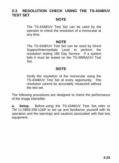
2-3 RESOLUTION CHECK USING THE TS-4348/UVTEST SET
NOTE
The TS-4348/UV Test Set can be used by theoperator to check the resolution of a monocular atany time.
NOTEThe TS-4348/UV Test Set can be used by DirectSupport/Intermediate Level to perform theresolution testing 180 Day Service. If a systemfails it must be tested on the TS-3895A/UV TestSet.
NOTE
Verify the resolution of the monocular using theTS-4348/UV Test Set at every opportunity. Theresolution cannot be accurately measured withoutthe test set.
The following procedures are designed to check the performanceof the image intensifier.
a. Setup. Before using the TS-4348/UV Test Set, refer toTM 11-5855-299-12&P to set up and familiarize yourself with itsoperation and the warnings and cautions associated with that testequipment.

2-24
NOTE
• The resolution test must be performed in adarkened area. Your eyes must be dark-adaptedto perform this test. Review the following testprocedure before entering the dark area.
• Expect cosmetic blemishes, such as chicken wire,black spots, and fixed-pattern noise, to stand outwhile viewing through the TS-4348/UV Test Setwhen it is on the high light level. This isacceptable.
• The rejection of any MNVD for cosmetic defectsmust be based on an outdoor evaluation and notthe TS-4348/UV Test Set.
b. Low Light and High Light Resolution Test Procedure.Test the monocular for low light and high light resolutionperformance according to the following steps.
(1) Place the HIGH/LOW switch on the test set to the LOWposition.
(2) Install the LIF per paragraph 2-10.
(3) Turn off the room light and let your eyes adjust to thedark.
(4) Turn on the test set by setting the “II/OFF/III” switch tothe “III” position.
(5) Turn on the monocular and insert it into the test port onthe test set.

2-25
(6) Look through the monocular and view the projectedpattern (see Figure 2-2). If necessary, focus the eyepiece lens andthen the objective lens to obtain the sharpest image.
(7) The MNVD monocular must be able to resolve Group 2,Element 2, under low light conditions to pass the test. If the MNVDdoes not pass the test, return it to maintenance for repair. Theoperator must document resolution failures on the maintenancerecord.

2-26
Figure 2-2. TS-4348/UV Test Set Pattern.

2-27
NOTE
For a pattern to be resolvable, three vertical barsand three horizontal bars must be visible.
(8) Flip the HIGH/LOW switch to the HIGH position.
(9) Again, look through the monocular and view theprojected pattern (see Figure 2-2). If necessary, refocus theobjective lens and then the eyepiece lens to obtain the sharpestimage.
(10) The MNVD must be able to resolve Group 3, Element 5,under high light conditions to pass the test. If the monocular doesnot pass the test, send it to a higher level of maintenance forrepair.
NOTE
When using the TS-4348/UV Test Set, you are notviewing the entire image intensifier. Therefore,operational and cosmetic inspections must bedone without the test set as specified in paragraph2-4.
(11) Look for flashing, flickering, or other nonstable behaviorof the image intensifier. Also check the image intensifier for otheroperational defects described in paragraph 2-4. To view the imageintensifier under low light conditions, flip the HIGH/LOW switch tothe LOW position and allow your eyes to become accustomed tothe dark. If any unacceptable conditions are noted, send to ahigher level of maintenance for repair.

2-28
2-4 INSPECTION CRITERIA FOR PROPER IMAGEINTENSIFIER OPERATION
a. General. As directed in the Preventive Maintenance Checksand Services table, image intensifier operation must be checkedbefore each mission. This section provides information for theoperator concerning what to look for, how to look for it, and how todetermine if the MNVD should be returned to the maintainer. Theoperator (Army only) must record all conditions on theappropriate maintenance forms and describe the specificdefects and sign it so the maintainer can take correctiveaction.
Perform the following inspection in the dark.
To perform this inspection, attach the monocular to the headmountas described in paragraph 2-6a and turn the power switch to theON position. Look through the monocular and view the image.
There are two groups of “defects” you may encounter – operationaldefects and cosmetic blemishes. Operational defects are animmediate cause to reject the MNVD. Cosmetic blemishes are nota cause for rejection unless they become severe enough tointerfere with the ability to perform the mission. The rejection ofany MNVD for cosmetic defects must be based on an outdoorevaluation and not the TS-4348/UV Test Set.
b. Operational Defects. These defects relate to the reliability ofthe image intensifier and are an indication of instability. Ifidentified, they are an immediate cause for rejecting the MNVD.They include shading, edge glow, flashing, flickering, andintermittent operation.
CAUTION

2-29
(1) Shading. If shading is present, you will not see a fully circular image (see Figure 2-3). Shading is very dark and you cannot see an image through it. Shading always begins on the edge and migrates inward eventually across the entire image area. Shading is a high contrast area with a distinct line of demarcation. Return the MNVD to the maintainer.
Figure 2-3. Shading.
NOTE
Make sure the shading is not the result of improper eye-relief adjustment (refer to paragraph 2-19).

2-30
(2) Edge Glow. Edge glow is a bright area (sometimessparkling) in the outer portion of the viewing area (see Figure 2-4).To check for edge glow, block out all light by cupping a hand overthe objective lens. If the image intensifier is displaying edge glowthe bright area will still show up. Return the MNVD to themaintainer.
Figure 2-4. Edge Glow.
(3) Flashing, Flickering, or Intermittent Operation. Theimage may appear to flicker or flash. If there is more than oneflicker, check for loose battery cartridge or weak batteries. If weakor loose batteries are not the problem return the MNVD to themaintainer.

2-31
c. Cosmetic Blemishes. These are usually the result ofmanufacturing imperfections that do not affect intensifier reliabilityand are not normally a cause for rejecting an MNVD. However,some types of blemishes can get worse over time and interferewith the ability to perform the mission. If you believe a blemish iscause for rejection, record the specific nature of the problem on themaintenance forms and identify the position of the blemish byusing the clock method and approximate distance from the center(e.g., 5 o’clock toward the outside, 2:30 near the center, or 1:00midway). The following are cosmetic blemishes:
(1) Bright Spots. A bright spot is a small, nonuniform, brightarea that may flicker or appear constant (Figure 2-5). Not all brightspots make the MNVD rejectable. Cup your hand over theobjective lens to block out all light. If the bright spot remains,return the MNVD to the maintainer. Bright spots usually go awaywhen the light is blocked out. Make sure any bright spot is notsimply a bright area in the scene you are viewing. Bright spotsare acceptable if they do not interfere with the operator'sability to view the image or to perform the mission.

2-32
Figure 2-5. Bright Spots and Emission Points.
(2) Emission Points. A steady or fluctuating pinpoint ofbright light in image area that does not go away when all light isblocked from the objective lens of the monocular (Figure 2-5). Theposition of an emission point within the image area does not move.Not all emission points make the MNVD rejectable. Make sure anyemission point is not simply a point light source in the scene youare viewing. Emission points are acceptable if they do notinterfere with the operator's ability to view the image or toperform the mission.
(3) Black Spots. These are cosmetic blemishes in theimage intensifier or dirt or debris between the lenses. Black spotsare acceptable as long as they do not interfere with viewing theimage. No action is required if this condition is present unlessthe spots interfere with the operator’s ability to view theimage or to perform the mission.

2-33
(4) Fixed-Pattern Noise. This is usually a cosmetic blemishcharacterized by a faint hexagonal (honeycomb) patternthroughout the viewing area that most often occurs at high lightlevels or when viewing very bright lights (see Figure 2-6). Thispattern can be seen in every image intensifier if the light level ishigh enough. This condition is acceptable as long as thepattern does not interfere with the operator’s ability to viewthe image or to perform the mission.
Figure 2-6. Fixed-Pattern Noise.

2-34
(5) Chicken Wire. An irregular pattern of dark thin lines inthe field-of-view either throughout the image or in parts of theimage area (see Figure 2-7). Under the worst case condition,these lines will form hexagonal or square-wave shaped lines. Noaction is required if this condition is present unless itinterferes with the operator’s ability to view the image or toperform the mission.
Figure 2-7. Chicken Wire.

2-35
Section III. Assembly and Preparation for Use
This chapter contains the information necessary to prepare themonocular for operation. This includes unpacking (2-5), batteryinstallation (2-6), eyecup and eyeguard installation (2-7), demistshield installation (2-8), sacrificial window installation (2-9), LIFinstallation (2-10), headmount installation and adjustment (2-11),headmount/helmet mount adapter installation (2-12), helmet mountinstallation to helmet (2-13), alternate helmet mount installation tohelmet (2-13b), headmount installation with protective mask (2-14),weapon mount installation (2-15), compass installation (2-16) and3X magnifier installation (2-17).
2-5 UNPACKING
The following steps must be accomplished prior to each missionwhere the MNVD is used.
Relieve air pressure inside shipping and storagecase by pressing in on opposite sides of the casebefore releasing latches.
(1) Release the latch securing top of shipping and storagecase and open.
(2) Check contents for completeness (see Figure 1-1).
(3) Remove carrying case. Open carrying case (Figure 1-1), remove MNVD, and check contents for completeness.
(4) Inspect the monocular for obvious evidence of damageto optical surfaces, body, eyecup, eyeguard, power switch, batterycartridge, etc. Ensure that all optical surfaces are clean and readyfor use. Clean with lens paper.
CAUTION

2-36
2-6 INSTALLATION OF BATTERIES
To protect the image intensifier, keep the objectivelens cap on when the monocular is not in use orwhen using the monocular in daylight conditions.
The MNVD operates with two AA batteries. Batteries are notsupplied with the MNVD and must be obtained separately.
Table 2-3. Estimated Battery Life.
BATTERYTYPE
TEMPERATURE NEGLIGIBLEIR SOURCEUSAGE
IR SOURCEUSAGE 10%OF THETIME
AA Alkaline 21°C(70°F) 60 Hrs 55 HrsAA Lithium L91 21°C(70°F) 70 Hrs 65 HrsAA Alkaline -20°C(-4°F) 12 Hrs 10 HrsAA Lithium L91 -20°C(-4°F) 60 Hrs 55 Hrs
At operating temperatures below -20°C (-4°F), Alkaline batteriesare not recommended, as operating life will be severely reduced.Lithium-iron disulfide L91 1.5V AA batteries should be used below-20°C (-4°F).
• Make certain the power switch is in the OFFposition before installing the batteries.
CAUTION
CAUTION

2-37
• Do not mix battery types (i.e., Alkaline andLithium).
Install the AA batteries as follows.
(1) Remove the battery cartridge by squeezing the two tabstogether and pulling out.
(2) Observe polarity, as indicated on the inside of thebattery cartridge, and insert the batteries into battery cartridge(Figure 2-8). In addition, some battery cartridges have a bubblemolded into the top to show the + for proper orientation of thebatteries.
Figure 2-8. Battery, Eyecup and Eyeguard Installation.
(3) Replace battery cartridge by pushing cartridge atpressure points into the housing as shown, making sure bothlatches on either side are engaged. You will feel them click intoplace.

2-38
2-7 INSTALLATION OF EYECUP OR EYEGUARD
Perform the following procedure to install eyecup or eyeguard ontothe monocular. Refer to Figure 2-8.
(1) Carefully press the eyecup or eyeguard over the end ofthe eyepiece lens.
(2) Rotate the eyecup or eyeguard into proper viewingposition. Adjust for best fit. The eyecup must seal around youreye and prevent the green glow from escaping.
2-8 INSTALLATION OF DEMIST SHIELD
Perform the following procedures to install the demist shield on theeyepiece lens. Refer to Figure 2-8.
If the demist shield needs to be cleaned, refer toparagraph 3-2 for cleaning. If the demist shield iswiped while wet or with wet lens paper, you willdamage the coating.
NOTE
If inclement operating conditions are expected toexist (e.g. significant temperature change and highhumidity), install demist shield to minimizeeyepiece lens fog prior to execution of mission.
(1) Carefully remove the eyecup or eyeguard.
(2) Carefully press the demist shield onto the eyepiece. Becareful not to smudge the eyepiece lens or demist shield.
(3) Replace the eyecup or eyeguard (see paragraph 2-7).
CAUTION

2-39
2-9 INSTALLATION OF SACRIFICIAL WINDOW
Perform the following procedure to install the sacrificial window.Refer to Figure 2-8.
If adverse operating conditions (dust or sand) areexpected to exist, attach the sacrificial window toprotect the objective lens from scratches or otherdamage.
(1) If the objective lens cap is in place, remove it.
(2) Carefully push the sacrificial window onto the objectivelens until it stops. Turn the sacrificial window clockwise until itsnaps into place.
2-10 INSTALLATION OF LIF
Perform the following procedure to install the LIF onto the objectivelens.
(1) Remove the container/wrench (Figure 1-1) from thecarrying case pouch.
Be careful not to touch glass surfaces. If you getfingerprints or contamination on glass surfaces,use lens paper to clean the LIF. If moisture isneeded, use your breath to mist the surface of theglass.
CAUTION
CAUTION

2-40
(2) If the objective lens cap or sacrificial window is on theobjective lens of the monocular, remove it.
(3) Carefully open the container/wrench and remove theLIF. Refer to Figure 2-9.
Figure 2-9. LIF.
(4) Hold the LIF by the ridged end (see Figure 2-11) andthread it clockwise, into the end of the objective lens.
Do not overtighten the LIF into the objective lens.
(5) Using the ridged side of the container/wrench as awrench, engage the ridges on the container with the ridges on theLIF and tighten the LIF handtight.
CAUTION

2-41
(6) Place the empty container/wrench back into the carryingcase pouch.
(7) Install the objective lens cap or the sacrificial windowonto the end of the objective lens and cover the LIF.
NOTE
The LIF must be used at all times unless directedby the unit commander, to remove the LIF, basedupon his/her assessment of the laser threat in thetheater of operations.
2-11 INSTALLATION AND ADJUSTMENT OFHEADMOUNT
Perform the following procedures for donning the headmount.
NOTE
Do not don the headmount while the monocular isattached.
(1) Prior to donning the headmount, loosen the four ends ofthe chinstrap approximately two inches from the sliding bar buckles(Figure 2-10).
(2) Snap the front and rear snaps (Figure 2-10) in place.
NOTE
If the headmount is too loose, remove theattached thin browpad (Figure 2-10) and replacewith either the medium or thick browpad stored inthe carrying case. Refer to paragraph 3-3a forremoval and replacement of the browpads.

2-42
Figure 2-10. MNVD Headmount Adjustments.
(3) With both hands grasp the neck pad (Figure 2-10) andpull the harness over your head and the neck pad down to theback of your neck.

2-43
(4) Holding the chin cup in position on chin, adjust bothsides of the chinstrap until you feel light pressure against yourchin. (DO NOT TIGHTEN.)
(5) Maintain the position of the chin cup and remove anyslack from the chinstrap. (DO NOT TIGHTEN.)
(6) Ensure that the cross-strap is not twisted and removeslack by adjusting the vertical adjustment at the neck pad.
(7) Adjust chinstrap and vertical adjustment until the chincup and headband are in a comfortable but firm position.
NOTE
After installing the monocular, minor strapadjustments may be necessary to achievecomfort.
(8) Install the headmount/helmet mount adapter (refer toparagraph 2-12).
(9) Refer to paragraph 2-19 for operating procedures.

2-44
2-12 INSTALLATION OF HEADMOUNT/HELMETMOUNT ADAPTER
Install the headmount/helmet mount adapter (Figure 1-1) into themonocular by aligning thumbscrew to hole and tightening asshown in Figure 2-11. There is an alignment boss on theheadmount/helmet mount adapter that fits into a groove on themonocular. Make sure the boss on the adapter fits into the grooveon the monocular.
Figure 2-11. Headmount/Helmet Mount AdapterInstallation.

2-45
2-13 INSTALLATION OF HELMET MOUNT TO HELMET
a. Using Helmet Mount Strap.
(1) Remove the helmet mount from the carrying case. Referto Figure 2-12 for helmet mount features.
Figure 2-12. Installation of Helmet Mount.
(2) Press the release (Figure 2-13) to remove the mountfrom the helmet mount bracket.

2-46
Figure 2-13. Helmet Mount.
(3) Make sure the strap is laced onto the helmet mountbracket as shown in Figure 2-12.
(4) With catch (see Figure 2-12) in forward most position,place the strap over the top of the helmet center (see Figure 2-13).
(5) Hook the rear bracket (see Figure 2-12) on the center ofthe back of the helmet and lay the strap with helmet mount bracketover the top of the helmet.
(6) Hook the helmet mount bracket in the center of the frontlip of the helmet and hold it in place (see Figure 2-13).
(7) With the buckle lever open, take up the slack in the strapusing the catch. Close the buckle lever.

2-47
(8) Disengage the nape strap latch on the left side of napestrap.
(9) Don the helmet. Do not fasten the helmet chinstrap.
(10) Engage the nape strap at the nape strap latch. Tensionthe nape strap for a stable fit, then install and tension the helmetchinstrap. The brow of the helmet should be parallel to the groundand the helmet stable on the head.
(11) Insert the top edge of the mount under the keeper on thehelmet mount bracket and rotate downward until the latch engages(see Figure 2-14). To release the mount from the helmet bracket,press the release and pull forward and down.
Figure 2-14. Reassembly of Helmet Mount.

2-48
b. Marine Corps Only – Using Existing Helmet Screw (nostrap).
NOTE
Refer to Figures 2-14 and 2-15 for reference anddefinition of terms.
Figure 2-15. Helmet Mount.
(1) Remove the helmet mount from the carrying case.
(2) Press the release to remove the mount from the helmetmount bracket.

2-49
(3) Unthread the strap from the helmet mount bracket.Unsnap the rear snap and remove the rear bracket from the strap.The nape strap should remain attached to the rear bracket.
NOTE
Place the strap in the carrying case – it is not usedfor this mounting method.
(4) Find the screw located in the front, center of the helmet.Using a flat tip screwdriver, remove the screw. Hook the helmetmount bracket on the front of the helmet and center it over the holewhere the screw was removed.
(5) Insert the screw removed in step 4 through the hole inthe helmet mount bracket and through the helmet (see Figure 2-15).
(6) Align the nut on the helmet’s interior strapping to thehole and tighten the screw with a flat tip screwdriver.
(7) Attach the mount to the helmet mount bracket. Insertthe top edge of the mount under the keeper on the helmet mountbracket and rotate downward until the latch engages (see Figure 2-14). To release the mount from the helmet bracket, press therelease.
(8) Find the screw located in the lower rear, center of thehelmet. Using a flat tip screwdriver, remove the screw. Hook therear bracket on the lower rear of the helmet and center it over thehole where the screw was removed.
(9) Insert the screw removed in step 8 through the hole onthe rear bracket and through the helmet.
(10) Align the nut to the hole and tighten the screw with theflat tip screwdriver.

2-50
(11) Disengage the nape strap latch on left side of napestrap.
(12) Don the helmet. Do not fasten the helmet chinstrap.
(13) Engage the nape strap at the nape strap latch. Tensionthe nape strap for a stable fit, then install and tension the helmetchinstrap. The brow of the helmet should be parallel to the groundand the helmet stable on the head.
(14) Insert the top edge of the mount under the keeper on thehelmet mount bracket and rotate downward until the latchengages. To release the mount from the helmet bracket, press therelease and pull forward and down.
2-14 INSTALLATION OF HEADMOUNT WITHPROTECTIVE MASK
Perform the following procedures for donning headmount withprotective mask.
(1) Place protective mask on your head per the instructionsprovided with the protective mask.
When installing the headmount over the protectivemask, be careful not to break the protective maskseal around your face.
(2) Install the headmount per the instructions in paragraph2-11.
NOTE
It may be necessary to remove the browpad(Figure 2-10) when wearing the headmount over aprotective mask.
WARNING
2-51
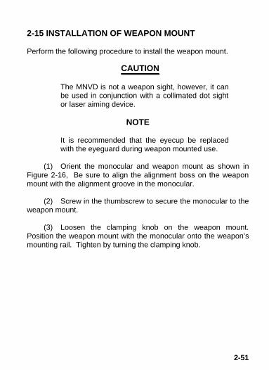
2-15 INSTALLATION OF WEAPON MOUNT
Perform the following procedure to install the weapon mount.
The MNVD is not a weapon sight, however, it canbe used in conjunction with a collimated dot sightor laser aiming device.
NOTE
It is recommended that the eyecup be replacedwith the eyeguard during weapon mounted use.
(1) Orient the monocular and weapon mount as shown inFigure 2-16, Be sure to align the alignment boss on the weaponmount with the alignment groove in the monocular.
(2) Screw in the thumbscrew to secure the monocular to theweapon mount.
(3) Loosen the clamping knob on the weapon mount.Position the weapon mount with the monocular onto the weapon’smounting rail. Tighten by turning the clamping knob.
CAUTION

2-52
Figure 2-16. Weapon Mount Usage.
NOTE
There is a ratchet in the weapon mount thatprevents overtightening of the clamp. Turn untilthe knob clicks.
(4) Check the position of the monocular by holding theweapon in your normal firing position. Adjust the fore/aft positionof the monocular as necessary by loosening the clamping knoband repositioning the weapon mount on the weapon’s mountingrail.

2-53
2-16 INSTALLATION OF COMPASS
• Use of the compass with the plasticheadmount or the plastic helmet mount willresult in inaccurate compass readings. Themagnet cannot be removed from thesemounts.
• The magnet must be removed from theruggedized metal helmet mount beforeinstallation of the compass. Failure to do sowill result in inaccurate compass readings.
• If the magnet is not removed, turn theruggedized metal helmet mount in to unitmaintenance for removal. See Figure 2-17for location of magnet.
CAUTION

2-54
NOTE
• Prepare the monocular for operation.
• Leave LIF in place when installing thecompass.
(1) If the sacrificial window or objective lens cap is in place,remove it.
(2) Turn monocular on.
(3) Rotate the objective lens focus completelycounterclockwise (while looking through the monocular).
NOTE
The o-ring must be in place in the compass inorder for the compass to fit properly.
(4) Press the compass onto the objective lens at an angleusing your left hand. Slowly turn the compass counterclockwiseuntil it is in the vertical position (with compass illumination buttonpointing down). See Figure 2-18.
(5) Ensure that the compass fits tightly to the objective lens.
(6) Refer to paragraph 2-23 for operation of the compass.

2-55
Figure 2-18. Compass Installation.
2-17 INSTALLATION OF 3X MAGNIFIER
The 3X magnifier can be threaded directly into the objective lens,with the LIF removed. It can also be threaded into the focus ringadapter and slipped on over the end of the objective lens with theLIF installed.
Figures 2-19 and 2-20 illustrate these installation procedures.

2-56
Figure 2-19. 3X Magnifier Installationwithout LIF.
Figure 2-20. 3X Magnifier Installationwith LIF.

2-57
Section IV. Operating Procedures
This section contains operating procedures for using the MNVD as hand-held, head mounted or helmet mounted monocular. Prior to operating the monocular, make certain that all the steps in Section III, Assembly and Preparation for Use, have been read and performed.
2-18 HAND-HELD OPERATION
Operate the monocular only under darkened conditions or use the objective lens cap to cover the objective lens for daylight conditions.
NOTE
When using the monocular without a mounting device, make sure to place the neck cord around your neck. (1) Ensure that the batteries are installed per paragraph 2-6. (2) Turn the power switch to ON.
NOTE
The sharpest image will be observed only when the objective lens and eyepiece lens are properly focused. (3) Rotate the diopter adjustment for the clearest view of the image intensifier screen. (4) Focus the objective lens while observing an object until the sharpest image is obtained.
CAUTION

2-58
2-19 HEAD MOUNTED OPERATION
Perform the following procedures for head mounted operation.
Operate the monocular only under darkenedconditions or use the lens cap to cover theobjective lens for daylight conditions.
(1) Ensure that batteries are installed per paragraph 2-6.
(2) Don the headmount per instructions in paragraph 2-11.
NOTE
To make it easier to align the monocular, eyecup,and eyepiece lens to the eye, depress the eyerelief adjustment and slide the headmount socketall the way forward before attaching themonocular.
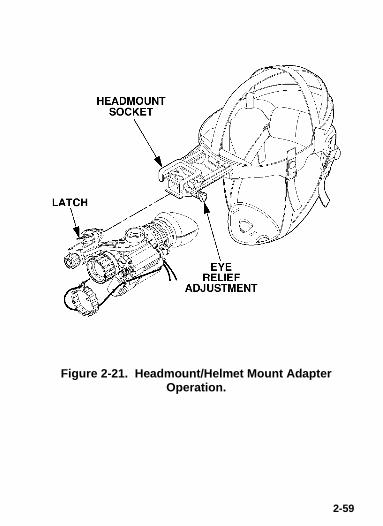
(3) Align the headmount/helmet mount adapter’s latch to theheadmount socket (Figure 2-21). Press and hold down the latchlever while installing the monocular into the headmount socket.Release the latch when the monocular fully engages the socket.
(4) Set your eye relief by depressing the eye reliefadjustment (Figure 2-21) and move the monocular back towardyour non-dominate eye until the eyecup comfortably seals aroundthe eye.
(5) Turn the monocular ON.
(6) Readjust the vertical adjustment (Figure 2-10) of theheadmount until the monocular is properly aligned with your eye.
CAUTION
2-59
Figure 2-21. Headmount/Helmet Mount AdapterOperation.

2-60
NOTE
The sharpest image will be observed only whenthe objective lens and eyepiece lens are properlyfocused.
(7) Rotate the diopter adjustment for the clearest view of theimage intensifier screen.
NOTE
Any readjustment of eye relief requiresreadjustment of the diopter.
(8) Adjust the eye relief distance by pressing the eye reliefadjustment and sliding monocular fore or aft to obtain a full field-of-view of the image. Reset the diopter adjustment for best image.
(9) Adjust the objective lens focus (Figure 2-1) whileobserving an object until the sharpest image is obtained.
2-20 HELMET MOUNTED OPERATION
Take some precaution when using/handling thehelmet mount. Most damage occurs when thehelmet mount is left on the helmet when notneeded for immediate use. Observe the followingcautions to significantly extend the useful life ofthe helmet mount.
CAUTION

2-61
• Do not use excessive force when changing theup/down position of the MNVD. Excessive forcecan break the headmount/helmet mount adapter.
• Do not drop or throw the helmet with the helmetmount attached to it.
• With the monocular in the flipped up position, donot flick the monocular down by shaking thehelmet. This places significant stress on thehelmet mount.
• Marine Corps Only – Use the helmet screws tomount the helmet mount bracket directly to thehelmet per paragraph 2-13b.
• All Other Services – Return the helmet and thehelmet mount to unit maintenance for directmounting of the bracket via the helmet screws.
Perform the following procedures for helmet mounted operation.
NOTE
The helmet mount provides two positions for theuser to position the MNVD. The flipped downposition allows the user to position the MNVDdirectly in front of the eyes. The helmet mountalso allows the user to rotate the MNVD to aflipped up position when the MNVD is not neededfor immediate use. Both the flipped down and theflipped up positions have a positive stop whichassures the user that the MNVD is in the correctposition.
CAUTION

2-62
NOTE
The headmount/helmet mount adapter allows theMNVD to be rotated from the left to the right eye orvice versa. The MNVD can be moved to theflipped up position with the headmount/helmetmount adapter positioned to either the left or theright.
(1) Ensure that the batteries are installed per paragraph 2-6.
(2) Don the helmet mount per instructions in paragraph 2-13.
(3) Place the monocular in the socket of the helmet mount.Set your eye relief by depressing the side buttons (or press downon side lever on metal mount) (see Figure 2-22) and carefullymove the monocular fore or aft until the eyecup comfortably sealsaround the eye. Readjust the helmet straps as required for verticaladjustment.
Figure 2-22. Tilt and Flip-up Assembly Mechanisms.

2-63
(4) Turn power switch to ON. Adjust the tilt by using the tiltadjustment lock knob (or tilt adjustment lever on metal mount)(Figure 2-22) until you obtain a comfortable viewing angle.
NOTEThe sharpest image will be observed only whenthe objective lens and eyepiece lens are properlyfocused.
(5) Rotate the diopter adjustment for the clearest view of theimage intensifier screen.
NOTE
Any readjustment of eye relief requires readjust-ment of the diopter.
(6) Adjust the eye relief distance by depressing the sidebuttons (Figure 2-22) (or press down on side lever on metal mount)and sliding monocular fore or aft to obtain a full field-of-view of theimage. Reset the diopter adjustment for best image.
(7) Adjust the objective lens focus (Figure 2-1) whileobserving an object until the sharpest image is obtained.
(8) To flip up, grasp the helmet tilt and flip-up assembly androtate upward and rearward until the latch is firmly engaged.
The monocular will not be turned off automaticallywhen flipped up. The monocular must be turnedoff by the power switch.
WARNING

2-64
(9) To flip down, grasp the helmet tilt and flip-up assemblyand rotate downward and forward until the latch is firmly engaged.
(10) Turn the power switch to the ON position to resumeviewing.
2-21 WEAPON MOUNTED OPERATION
NOTE
The MNVD can be used in conjunction with acollimated dot aiming device mounted on theforward mounting rail. The brightness control forthe aiming device should be set at or near it’sminimum setting.
Perform the following procedures for weapon mounted operation:
(1) Ensure that the batteries are installed per paragraph 2-6.
(2) Assemble the weapon mount to the monocular perparagraph 2-15, steps 1 and 2.
(3) Mount the monocular with adapter onto the M16/M4receiver rail per paragraph 2-15, steps 3 and 4.
(4) Rotate the diopter adjustment for the clearest view of theimage intensifier screen.
(5) Adjust the objective lens focus (Figure 2-1) whileobserving an object until the sharpest image is obtained.

2-65
2-22 IR SOURCE OPERATIONS
The IR source is a light that is invisible to theunaided eye for use during conditions of extremedarkness. However, the light from the IR sourcecan be detected by the enemy using night visiondevices.
NOTE
The purpose of the IR source is for viewing atclose distances up to 3 meters when additionalillumination is needed.
(1) Pull the power switch knob out and rotate clockwise tothe IR position. With the monocular held to the eye, observe that ared light appears in the eyepiece. This indicates that the IR sourceis operating.
(2) For momentary IR, turn the power switch clockwise(without pulling) past the ON position. Observe that a red lightappears in the eyepiece.
2-23 OPERATION WITH COMPASS
The compass illuminator can be seen by othersusing night vision devices.
WARNING
WARNING

2-66
You will get inaccurate readings, when using thecompass on any head or helmet mount with themagnet still installed. Only the magnet on themetal mount can be removed without causingdamage to the equipment, see paragraph 2-16.
NOTE
• The compass reading is the magnetic North,not true North.
• The compass reading is within 2° of correctabsolute magnetic bearing. Compassreadings with mounted monocular (headmount or helmet mount) can be up to 15° ofcorrect absolute magnetic bearing. Thisoccurs mostly in the East (90°) to West(270°) and less in the North (360°) to South(180°) reading. If the compass isinadvertently magnetized this could cause anadditional 15° error.
• The objective lens focus can be fine tunedafter installation, but in order to obtain anaccurate reading, the compass must bevertical. (The compass image must be level.)
(1) Install per paragraph 2-16.
(2) If necessary to more clearly view your distant object,adjust the objective lens focus slightly by gripping the compassand turning clockwise.
CAUTIONCAUTIONCAUTION

2-67
NOTE
• Increase brightness slowly. Excessivebrightness may burn a temporary image intothe image intensifier. Do not increasebrightness any more than is necessary toclearly read the compass heading.
• The monocular must be focused at or nearinfinity for proper compass operation.
(3) To view the compass through the monocular, grip thecompass with index finger on top and thumb on illumination buttonon bottom. Press button slowly with thumb until proper brightnessis obtained. The image should appear as shown in Figure 2-23.
(4) The compass readings should change when you moveyour head from side to side. Rotate or tap compass slightly toensure compass is operating correctly. Hold the monocular in alevel position to assure free rotation of the compass scale.
Figure 2-23. View Through Installed Compass.

2-68
(5) The tick mark closest to the center of the lighted displayis the compass bearing. The tick marks are in degrees, with longertick marks every five degrees and bearing labels every 10 degrees.
2-24 OPERATION WITH 3X MAGNIFIER
(1) Install per paragraph 2-17.
NOTE
The mated 3X magnifier and objective lens willturn as a unit to allow focusing.
(2) Grasp the 3X magnifier and focus while observing anobject until the sharpest image is obtained.
2-25 OPERATION WITH GAIN CONTROL
Turn the gain control (Figure 2-24) to balance the illumination inputto the eye.
Figure 2-24. Gain Control.

2-69
2-26 PREPARATION FOR STORAGE
(1) Shutdown. Perform the following procedures to shutdown the monocular.
(a) Turn the monocular power switch to the OFFposition.
(b) Remove the monocular from the headmount,helmet mount or weapon and remove the weapon mount from themonocular.
Do not carry batteries in pockets containing metalobjects such as coins, keys, etc. Metal objectscan cause the batteries to short circuit andbecome very hot.
(2) Packaging After Use.
(a) Remove battery cartridge and remove batteries.
(b) Inspect the battery housing for corrosion ormoisture. Clean and dry if necessary.
(c) Replace the battery cartridge.
(d) Remove the demist shield or sacrificial window ifinstalled. Install objective lens cap.
NOTE
• Prior to placing MNVD into carrying case,ensure MNVD and case are free of dirt, dust,and moisture.
• The monocular and helmet mount should notbe left on the helmet when the helmet isremoved.
WARNING

2-70
(e) Refer to Figure 1-1 for proper placement of demistshield, batteries, carrying case strap, lens paper, sacrificialwindow, manual, LIF, browpads, headmount, helmet mount,headmount/helmet mount adapter and weapon mount.
(f) Place the monocular into the shallow pocket of thecarrying case.
(g) Place the carrying case into the shipping andstorage case, close and latch (Figure 1-1).
(h) Return to storage area.
Section V. Operation Under Unusual Conditions
2-27 OPERATION IN DUSTY OR SANDY AREAS
Operation in dusty or sandy areas can pit andscratch the optical elements and damage themechanical components unless the precautionsgiven below are observed.
(1) Ensure that the sacrificial window is in place over theLIF.
(2) Avoid pointing the monocular into the wind unlessnecessary for operation.
(3) Keep the carrying case closed unless removing orreplacing items.
(4) Ensure that all dust and sand is removed from theMNVD and carrying case after operation.
CAUTION

2-71
2-28 OPERATION IN RAINY OR HUMID CONDITIONS
Operation in rainy or humid conditions can causecorrosion and deterioration of the MNVD unlessthe precautions given below are observed.
(1) Install the demist shield (paragraph 2-8).
(2) Keep the carrying case, and shipping and storage caseclosed unless removing or replacing items.
(3) Dry the monocular, mounts, and accessories afterexposure to rain or high humidity and before storage. This willprevent mildew from forming in the case.
(4) Do not store monocular in a wet carrying case or a wetshipping and storage case.
2-29 OPERATION IN SALT WATER AREAS
After exposure to salt water, clean the MNVD (paragraph 3-2).
CAUTION

2-72
2-30 OPERATION IN NUCLEAR, BIOLOGICAL ANDCHEMICAL (NBC) ENVIRONMENTS
Do not use contaminated eyecup or eyeguard.They must be replaced.
(1) Decontamination – Wear a protective mask while usingMNVD after decontamination process.
(2) Hardness – Do not use DS-2 for decontaminating theMNVD. To decontaminate, use 5% sodium hypochlorite and rinsewith hot (158° F) soapy water.
2-31 OPERATION IN LASER THREAT ENVIRONMENTS
NOTE
The LIF is a light-protection filter. This filter mustbe used at all times unless directed by the unitcommander, to remove the LIF based upon his/herassessment of the laser threat in the theater ofoperations. Use of this filter will result in a slightreduction in system gain.
Install the LIF as described in paragraph 2-10.
WARNING

3-1
CHAPTER 3MAINTENANCE INSTRUCTIONS
Section I. Lubrication Instructions
No lubrication is required.
Section II. Troubleshooting Procedures
3-1 TROUBLESHOOTING
Table 3-1 lists common malfunctions that you may find with yourequipment. Perform the tests, inspections and corrective actionsin the order they appear in the table.
This table cannot list all the malfunctions that may occur, all thetests and inspections needed to find the fault, or all the correctiveactions needed to correct the fault. If the equipment malfunction isnot listed or actions listed do not correct the fault, notify yourmaintainer.

3-2
CORRECTIVE ACTION
Turn power switch to RESET/OFF position and then ON.
Replace batteries or install correctly.
If IR source still fails to activate, refer to higher level of maintenance.
Refer to higher level of maintenance.
Refocus.
Clean lens surfaces per paragraph 3-2.
TEST OR INSPECTION
Visual.
Check for defective, missing or improperly installed batteries.
In a dark location with system turned on, activate IR source. Visually check IR source operation; scene should brighten.
Visual.
Check objective lens or eyepiece lens focus.
Check for fogging or dirt on objective lens or eyepiece lens.
Table 3-1. Operator’s Troubleshooting.
MALFUNCTION
1. Monocular fails to activate.
2. IR source fails to activate.
3. IR source indicator fails to activate.
4. Poor image quality.

3-3
CORRECTIVE ACTION
Readjust for proper eye relief distance.
If eyecup is defective, refer to higher level of maintenance.
If damaged, refer to higher level of maintenance.
If o-ring is missing, refer to higher level of maintenance.
If damaged, refer to higher level of maintenance.
TEST OR INSPECTION
Check eye relief distance.
Check eyecup for resiliency.
Check to see if the diopter adjustment is bent or broken.
Visually inspect for the presence of an o-ring.
Check for damaged battery cartridge.
Table 3-1. Operator’s Troubleshooting - Continued.
MALFUNCTION
5. Light visible around eyecup.
6. Diopter adjustment cannot be made.
7. Battery cartridge difficult to open.

3-4
CORRECTIVE ACTION
If damaged, refer to higher level of maintenance.
Clean socket and latch.
If damaged, return either headmount or helmet mount socket and head- mount/helmet mount adapter to higher level of maintenance.
TEST OR INSPECTION
Check for defective buckles, fasteners or straps.
Check socket or latch for dirt.
Check socket or latch for damage.
Table 3-1. Operator’s Troubleshooting - Continued.
MALFUNCTION
8. Head straps cannot be tightened.
9. Headmount or helmet mount socket and headmount/ helmet mount adapter latch does not catch.

3-5
CORRECTIVE ACTION
If damaged, refer to higher level of maintenance.
Clean threads.
If damaged, refer to higher level of maintenance.
Refer to higher level of maintenance.
Refer to higher level of maintenance.
Make sure the monocular is focused for infinity. If so, and compass display is still not clear, refer to higher level of maintenance.
TEST OR INSPECTION
Inspect mounting hardware for damage.
Check for dirt in threads.
Check for damaged LIF.
Visual.
Visual.
Visual.
Table 3-1. Operator’s Troubleshooting - Continued.
MALFUNCTION
10. Helmet mount will not tighten to helmet.
11. LIF will not thread in or obstruct view.
12. Compass does not illuminate.
13. Compass will not stay on the goggles.
14. Compass display is not clear.

3-6
CORRECTIVE ACTION
If damaged, refer to higher level of maintenance.
TEST OR INSPECTION
Visual.
Perform the following test under daylight or bright room light (not fluorescent light).
Place the objective lens cap on the objective lens. Turn monocular ON and observe that it cuts off within 70 ±30 seconds after energized.
Turn monocular OFF and then ON to reenergize monocular.
Table 3-1. Operator’s Troubleshooting - Continued.
MALFUNCTION
15. Monocular does not cut off when exposed
to high light.

3-7
Section III. Operator’s Maintenance Procedures
3-2 CLEANING THE MNVD
• The monocular is a precision electro-opticalinstrument and must be handled carefully.
• Do not scratch the external lens surfaces ortouch them with your fingers.
• Wiping demist shield with lens paper whilewet or with wet lens paper can damage thecoating.
Clean monocular with water if necessary and dry thoroughly.Clean lenses with lens paper (and water if necessary, except forthe demist shield).
3-3 HEADMOUNT MAINTENANCE
a. Browpad Replacement. Replace the browpad whencracked, torn, or contaminated. Perform the following proceduresto remove and replace the browpad.
(1) Firmly grasp the headmount and remove the oldbrowpad.
(2) Gently press on the new browpad. Lightly smoothout any wrinkles in the new browpad.
CAUTION

3-8
b. Neck Pad Reinstallation. During operation of the MNVD,it is possible for the neck pad to become separated from itsposition on the headband. Perform the following procedure toreinstall the neck pad.
(1) Lift the upper headband strap retention tab (seeFigure 3-1) allowing the neck pad strap to be inserted underneath.
(2) Slip the neck pad strap all the way under the upperstrap retention tab and then pull the lower part of the neck padstrap under the lower strap retention tab.
Figure 3-1. Reinstalling the Neck Pad.
(3) Repeat steps 1 and 2 for the other side of theheadband and neckband if necessary.

3-9
c. Lacing the Sliding Bar Buckles. While donning andadjusting the headmount, it is possible for a strap to slip out of aslide fastener. Perform the following procedure to adjust the strapand sliding bar buckle.
(1) Thread the strap from the inside of the buckle overthe moveable sliding bar (see Figure 3-2). Thread the strap backthrough the buckle but this time under the moveable sliding barand over the serrated part of the buckle.
Figure 3-2. Threading the Sliding Bar Buckles.
(2) Pull the strap through the buckle and tighten asnecessary.
(3) Repeat steps 1 and 2 for other straps and bucklesthat may have come undone.

3-10
3-4 NECK CORD MAINTENANCE
The neck cord (Figure 1-1) may be broken, frayed, or loose at oneor both ends.
If loose, re-tie cord. If broken or severely frayed, install new cordas follows:
(1) Insert ends through monocular holes from the rear.
(2) Then through one hole of battery cartridge.
(3) Thread right cord end through hole in objective lens cap.
(4) Tie a knot in each end.

A-1
APPENDIX AREFERENCES
A-1 SCOPE
This appendix lists all the forms, field manuals, technical manuals,and miscellaneous publications referred to in this manual.
A-2 FORMS
Inspection and Maintenance Record DA 2404
Product Quality Deficiency Report SF 368
Recommended Changes toPublications and Blank Forms
DA 2028
A-3 FIELD MANUALS
First Aid for Soldiers FM 21-11
A-4 TECHNICAL MANUALS
Operator’s and Unit MaintenanceManual (including Repair Parts andSpecial Tools List) for Test Set,Electronic Systems, TS-4348/UV
TM 11-5855-299-12&P
Procedures for Destruction ofElectronic Materiel to Prevent EnemyUse (Electronics Command)
TM 750-244-2

A-2
APPENDIX AREFERENCES - Continued
A-5 MISCELLANEOUS PUBLICATIONS
Army Medical DepartmentExpendable/Durable Items
CTA 8-100
Consolidated Index of ArmyPublications and Blank Forms
DA Pam 25-30
Expendable/Durable Items (ExceptMedical, Class V Repair Parts, andHeraldic Items)
CTA 50-970
The Army Maintenance ManagementSystem (TAMMS)
DA Pam 738-750
A-6 MARINE CORPS USE
Equipment Record Procedures TM 4700-15/1
Marine Corps Publication DistributionSystem
MCPDS
Recommended Changes toPublications/Logistics-MaintenanceData Coding
NAVMC 10772

B-1
APPENDIX B
COMPONENTS OF END ITEM (COEI) ANDBASIC ISSUE ITEMS (BII) LISTS
INTRODUCTION
B-1 SCOPE
This appendix lists COEI and BII for the AN/PVS-14 to help youinventory items for safe and efficient operation of the equipment.
B-2 GENERAL
The COEI and BII information is divided into the following lists.
Components of End Item (COEI). This list is for informationpurposes only and is not authority to requisition replacements.These items are part of the AN/PVS-14. As part of the end item,these items must be with the end item whenever it is issued ortransferred between property accounts. Items of COEI areremoved and separately packaged for transportation or shipmentonly when necessary. Illustrations are furnished to help you findand identify the items.
Basic Issue Items (BII). These essential items are required toplace the AN/PVS-14 in operation, operate it, and to do emergencyrepairs. Although shipped separately packaged, BII must be withthe AN/PVS-14 during operation and when it is transferredbetween property accounts. Listing these items is your authority torequest/requisition them for replacement based on authorization ofthe end item by the TOE/MTOE. Illustrations are furnished to helpyou identify the items.

B-2
B-3 EXPLANATION OF COLUMNS IN THE COEI LISTAND BII LIST
Column (1), Illus Number. Gives you the number of the itemillustrated.
Column (2), National Stock Number. Identifies the stock number ofthe item to be used for requisitioning purposes.
Column (3), Description CAGEC and Part Number. Identifies theFederal item name (in all capital letters) followed by a minimumdescription when needed. The stowage location of COEI and BII isalso included in this column. The last line below the description isthe CAGEC (commercial and Government entity code) (inparenthesis) and the part number.
Column (4), Usable on Code. When applicable, gives you a codeif the item you need is not the same for different models ofequipment.
Column (5), U/M (Unit of Measure). Indicates how the item isissued for the National Stock Number shown in column (2).
Column (6), Qty Rqr. Indicates the quantity required.
Supply System Responsibility. (Marine Corps Only) A list inalphabetical sequence, of items that are furnished with and mustbe turned in with the end item. Any item requiring replacement isthe responsibility of the holding organization or using unit.
Collateral Material. (Marine Corps Only) A list, in alphabeticalsequence, of items that are supplied with the initial issue of an enditem and also retained by the unit.

B-3
5th Echelon Rehabilitation Program. (Marine Corps Only) Majoritems returned under this program will be evacuated under theprovision(s) of the applicable Marine Corps Order(s) with itemslisted under “Supply System Responsibility” rebuild andreplacement under the 5th Echelon Rehabilitation Program will belimited to these items only. Those items under the headingCollateral Material and using unit items shall be held by holdingorganizations/using units for application to replacement end items.
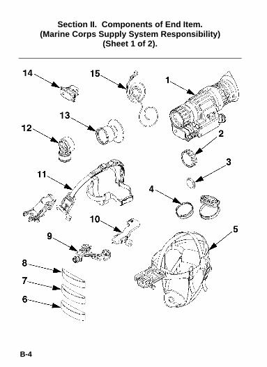
B-4
Section II. Components of End Item.(Marine Corps Supply System Responsibility)
(Sheet 1 of 2).

B-5
Section II. Components of End Item.(Marine Corps Collateral Material)
(Sheet 2 of 2).
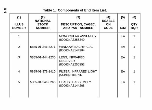
B-6
(6)
QTYRQR
1
1
1
1
1
(5)
U/M
EA
EA
EA
EA
EA
(4)USABLE
ONCODE
(3)
DESCRIPTION, CAGEC,AND PART NUMBER
MONOCULAR ASSEMBLY (80063) A3256340
WINDOW, SACRIFICIAL (80063) A3144264
LENS, INFRARED RECEIVER (80063) A3256353
FILTER, INFRARED LIGHT (54490) 5009737
HEADSET ASSEMBLY (80063) A3144268
(2)NATIONAL
STOCKNUMBER
5855-01-246-8271
5855-01-444-1230
5855-01-379-1410
5855-01-246-8266
Table 1. Components of End Item List.
(1)
ILLUSNUMBER
1
2
3
4
5

B-7
(6)
QTYRQR
1
1
1
1
1
(5)
U/M
EA
EA
EA
EA
EA
(4)USABLE
ONCODE
(3)
DESCRIPTION, CAGEC,AND PART NUMBER
BROWPAD ASSY, THICK (80063) A3144436
BROWPAD ASSY, MEDIUM (80063) A3144435
BROWPAD ASSY, THIN (80063) A3144280
ADAPTER, HEADSET (80063) A3256347
BRACKET, MOUNTING (80063) A3256348
(2)NATIONAL
STOCKNUMBER
5855-01-297-7847
5855-01-355-8600
5855-01-355-8599
5965-01-444-1216
5340-01-446-8588
Table 1. Components of End Item List - Continued.
(1)
ILLUSNUMBER
6
7
8
9
10

B-8
(6)
QTYRQR
1
1
1
1
1
(5)
U/M
EA
EA
EA
EA
EA
(4)USABLE
ONCODE
(3)
DESCRIPTION, CAGEC,AND PART NUMBER
MOUNT, VIEWER (80063) A3256368 or MOUNT, VIEWER (80063) A3260927
COMPASS ASSEMBLY (80063) A3187430
EYEGUARD, OPTICAL INSTRUMENT (80063) A3256345
COVER, BATTERY RETAINER (80063) A3256344 (MARINES ONLY)
(2)NATIONAL
STOCKNUMBER
5855-01-457-2953
5855-01-441-0401
5855-01-381-6052
6650-01-444-1229
6160-01-444-1208
Table 1. Components of End Item List - Continued.
(1)
ILLUSNUMBER
11
11
12
13
14

B-9
(6)
QTYRQR
1
1
1
1
1
(5)
U/M
EA
EA
EA
EA
EA
(4)USABLE
ONCODE
(3)
DESCRIPTION, CAGEC,AND PART NUMBER
CLIP, RETAINING (80063) A3260933
CASE, INFRARED EQUIPMENT (80063) A3187392
STRAPPING (80063) A3144267
CAP, PROTECTIVE, DUST (80063) A3144318
CORD, FIBROUS (80063) A3144306
(2)NATIONAL
STOCKNUMBER
5340-01-451-7737
5855-01-398-4284
5340-01-250-2431
5340-01-397-6608
4020-01-446-8097
Table 2. Components of End Item List
(1)
ILLUSNUMBER
15
16
17
18
19

B-10
(6)
QTYRQR
1
1
(5)
U/M
EA
EA
(4)USABLE
ONCODE
(3)
DESCRIPTION, CAGEC,AND PART NUMBER
OPERATOR’S MANUAL TM 11-5855-306-10
CASE, SHIPPING & STORAGE (80063) A3264350
(2)NATIONAL
STOCKNUMBER
Table 2. Components of End Item List
(1)
ILLUSNUMBER
20
21

B-11/12 blank
Basic I ssue Items
Not App licable

C-1
APPENDIX CADDITIONAL AUTHORIZATION LIST (AAL)
INTRODUCTION
C-1 SCOPE
This appendix lists additional items you are authorized for thesupport of the AN/PVS-14.
C-2 GENERAL
This list identifies items that do not have to accompany theAN/PVS-14 and that do not have to be turned in with it. Theseitems are all authorized to you by CTA, MTOE, TDA, or JTA.
C-3 EXPLANATION OF COLUMNS IN THE AAL
Column (1), National Stock Number. Identifies the stock number ofthe item to be used for requisitioning purposes.
Column (2), Description, Commercial and Government Entity Code(CAGEC), and Part Number (P/N). Identifies the Federal itemname (in all capital letters) followed by a minimum descriptionwhen needed. The last line below the description is the CAGEC(in parentheses) and the part number.
Column (3), Usable On Code. When applicable, gives you a codeif the item you need is not the same for different models ofequipment.
Column (4), U/M (Unit of Measure). Indicates how the item isissued for the National Stock Number shown in column (1).
Column (5), Qty Recm. Indicates the quantity recommended.

C-2
Using Unit Responsibility (Marine Corps Only). A list, inalphabetical sequence, of items that will not be issued with the enditem. They must be requisitioned, as required, through the supplysystem by the holding organization or the using unit.

C-3/4 blank
(5)
QTYRECM
2
2
1
1
(4)
U/M
EA
EA
EA
EA
(3)USABLE
ONCODE
(2)
DESCRIPTION, CAGEC,AND PART NUMB ER
BATTERY, NON- RECHARGEABLE (AA), 1.5 Vdc (80058) BA-3058/U
BATTERY, NONRECHARGEABLE (AA) (83740) L91, 1.5 Vdc
TEST SET, ELEC. SYS. TS-4348/UV (80063) A3139775
MAGNIFIER LENS ASSEMBLY (80063) A3256391
Table 1. Additi onal Aut horiza tion L ist.
(1)NATIONAL
STOCKNUMBER
6135-00-985-7845
6135-01-333-6101
6625-01-323-9584
5855-01-423-0817

D-1
APPENDIX DEXPENDABLE AND DURABLE ITEMS LIST
INTRODUCTION
D-1 SCOPE
This appendix lists expendable and durable items that you willneed to operate and maintain the AN/PVS-14. This list is forinformation only and is not authority to requisition the listed items.These items are authorized to you by CTA 50-970,Expendable/Durable Items (Except Medical, Class V Repair Parts,and Heraldic Items), or CTA 8-100, Army Medical DepartmentExpendable/Durable Items.
D-2 EXPLANATION OF COLUMNS IN THEEXPENDABLE/DURABLE ITEMS LIST
Column (1) - Item Number. This number is assigned to the entry inthe list and is referenced in the narrative instructions to identify theitem (e.g. “Use lubricating oil, item 25, APPENDIX D”).
Column (2) - Level. This column includes the lowest level ofmaintenance that requires the listed item (C = Operator/Crew).
Column (3) - National Stock Number. This is the NSN assigned tothe item, which you can use to requisition it.
Column (4) – Item Name, Description, Commercial andGovernment Entity Code (CAGEC), and Part Number (P/N). Thiscolumn provides the other information you need to identify theitem.
Column (5) - Unit of Measure (U/M). This code shows the physicalmeasurement or count of an item, such as gallon, dozen, gross,etc.

D-2
(5)
U/M
PK
(4)
ITEM NAME, DESCRIPTION,CAGE, PART NUMBER
PAPER, LENS(81348) A-A-50177, TYPE I, CLASS 5
(3)
NATIONALSTOCK
NUMBER
6640-01-459-4239
Table 1. Expendable and Durable Items List.
(2)
LEVEL
C
(1)
ITEMNUMBER
1

Index-1
SUBJECT INDEX
Para
A
Abbreviations, list of .................................................................. 1-8Additional Authorization List ......................................................C-1Adjustment (See specific adjustment.)Ambient temperature limits ...................................................... 1-12Appendices
A – References ...................................................................A-1B – Components of End Item (COEI) and Basic Issue
Items (BII) Lists............................................................B-1C – Additional Authorization List (AAL)................................C-1D – Expendable and Durable Items List ..............................D-1
BBasic Issue Items List................................................................B-1Battery
AA size.............................................................................. 1-12Alkaline ............................................................................. 1-12Installing.............................................................................. 2-6Life...................................................................................... 2-6Lithium .............................................................................. 1-12Low-battery indicator......................................... 1-10, 1-15, 2-1Polarity Indicators................................................................ 2-1Replacing............................................................................ 2-6Voltage..................................................................... 1-12, 1-15
Black spots......................................................................... 1-9, 2-4Bright spots ........................................................................ 1-9, 2-4Browpads .................................................................................. 1-9

Index-2
SUBJECT INDEX - Continued
Para
C
Capabilities.............................................................................. 1-10Case
Carrying ............................................................................ 1-11Shipping and Storage........................................................ 1-11
Caution...................................................................................... 1-9Characteristics......................................................................... 1-10Checks, preventive maintenance ............................................... 2-2Chicken wire....................................................................... 1-9, 2-4Cleaning the MNVD................................................................... 3-2Compass
Installation......................................................................... 2-16Operation .......................................................................... 2-23
Components of End Item List.....................................................B-1Corrosion prevention and control ............................................... 1-3Cross-reference list, nomenclature ............................................ 1-7Current .................................................................................... 1-12
D
Dark (or dark area) .................................................................... 1-9Data......................................................................................... 1-12
Electrical .................................................................. 1-12, 1-15Environmental ................................................................... 1-12Equipment......................................................................... 1-12Mechanical............................................................... 1-12, 1-13Optical...................................................................... 1-12, 1-14
Demist ShieldDescription ........................................................................ 1-11Installation........................................................................... 2-8
Destruction of materiel............................................................... 1-4

Index-3
SUBJECT INDEX - Continued
Para
Diopter ...................................................................................... 1-9Diopter Adjustment.................................................................... 2-1Dusty conditions ...................................................................... 2-27
E
Edge glow .......................................................................... 1-9, 2-4Electrical
Current.............................................................................. 1-12Function ............................................................................ 1-15Voltage.............................................................................. 1-12
Electronic circuit function ......................................................... 1-15Equipment
Characteristics, capabilities and features .......................... 1-10Data .................................................................................. 1-12Improvement recommendations .......................................... 1-5
Expendable and Durable Items List ...........................................D-1Eye Relief.................................................................................. 2-1Eyecup, installation.................................................................... 2-7Eyeguard, installation ................................................................ 2-7Eyepiece lens
Focus................................................................................ 1-12Operation ............................................................................ 2-1Range ............................................................................... 1-12

Index-4
SUBJECT INDEX - Continued
Para
F
Features .................................................................................. 1-10Field-of-view ............................................................................ 1-12Filter (see LIF)Fixed-pattern noise............................................................. 1-9, 2-4Flashing..............................................................................1-9, 2-4Flickering............................................................................1-9, 2-4Focus
Eyepiece (see Eyepiece lens)Objective (see Objective lens)
G
Gain control ............................................................... 2-1, 2-2, 2-25General information ................................................................... 1-1Glossary .................................................................................... 1-9
H
Hand-held operation ................................................................ 2-18Headmount/Helmet mount adapter installation......................... 2-12Head Mount
Installation......................................................................... 2-11Maintenance ....................................................................... 3-3Operation .......................................................................... 2-19
Helmet MountInstallation and adjustment................................................ 2-13Installation with protective mask ........................................ 2-14Operation .......................................................................... 2-20
High LightCut-Off .............................................................................. 1-15

Index-5
SUBJECT INDEX - Continued
Para
High Light (continued)Cut-Off .............................................................................. 1-15
Honeycomb (see Fixed-pattern noise)Humid conditions..................................................................... 2-28
I, J, K
Illumination required ................................................................ 1-12Image intensifier operation ...................................................... 1-14Infinity focus .............................................................................. 1-9Inspection
Criteria for proper image intensifier operation...................... 2-4Preventive maintenance...................................................... 2-2
Intermittent operation................................................................. 2-4IR source operations ............................................................... 2-22
L
Laser threat environments ....................................................... 2-31Latch ......................................................................................... 2-1LED On Indicator....................................................................... 2-1LIF
Description................................................................. 1-9, 1-11Installation......................................................................... 2-10
Lithium battery (see Battery)Location and description of major components ........................ 1-11Low-battery indicator
Description........................................................ 1-10, 1-15, 2-1Operation .......................................................... 1-10, 1-15, 2-1
Lubrication....................................................... Chapter 3, Section I
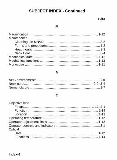
Index-6
SUBJECT INDEX - Continued
Para
M
Magnification ........................................................................... 1-12Maintenance
Cleaning the MNVD............................................................. 3-2Forms and procedures ........................................................ 1-2Headmount ......................................................................... 3-3Neck Cord ........................................................................... 3-4
Mechanical data ...................................................................... 1-12Mechanical functions ............................................................... 1-13Monocular ............................................................................... 1-11
N
NBC environments ..................................................................2-30Neck cord ...........................................................................2-2, 3-4Nomenclature ............................................................................ 1-7
O
Objective lensFocus ......................................................................... 1-12, 2-1Function ............................................................................ 1-14Location ............................................................................ 1-11
Operating temperature............................................................. 1-12Operator adjustment limits ....................................................... 1-12Operator controls and indicators ................................................ 2-1Optical
Data .................................................................................. 1-12Functions .......................................................................... 1-14

Index-7
SUBJECT INDEX - Continued
ParaP
PMCS........................................................................................ 2-2Power
Source ..................................................................... 1-12, 1-15Switch ................................................................................. 2-1
Preparation for storage............................................................ 2-26Purpose of equipment ...................................................... 1-1, 1-10
R
Rainy conditions ...................................................................... 2-28Reference list ............................................................................ 1-7References................................................................................A-1Resolution check using the TS-4348/UV Test Set ..................... 2-3
S
Sacrificial WindowDescription........................................................................ 1-11Installation........................................................................... 2-9
Salt water areas ...................................................................... 2-29Sandy conditions ..................................................................... 2-27Scintillation ................................................................................ 1-9Scope........................................................................................ 1-1Shading.............................................................................. 1-9, 2-4Shipping and storage case ...................................................... 1-11Shutdown (see Preparation for storage)Storage temperature................................................................ 1-12

Index-8
SUBJECT INDEX - Continued
Para
T
Temperature limits................................................................... 1-12Test Set, TS-4348/UV................................................................ 2-3Troubleshooting......................................................................... 3-13X Magnifier
Installation......................................................................... 2-17Operation .......................................................................... 2-24
U, V
Unpacking ................................................................................. 2-5Vertical adjustment ..................................................................2-19Voltage ........................................................................... 1-12, 1-15
W, X, Y, Z
Warning..................................................................................... 1-9Warranty Information ................................................................. 1-6Weapon mount
Description ........................................................................ 1-11Installation......................................................................... 2-15
Weapon MountedOperation .......................................................................... 2-21
WeightMonocular ......................................................................... 1-12Shipping and storage case ................................................ 1-12

By Order of the Secretary of the Army: ERIC K. SHINSEKI General, United States Army Chief of Staff Official: JOEL B. HUDSON Administrative Assistant to the Secretary of the Army 0017903 By Order of the Secretary of the Marine Corps: RANDALL P. SHOCKEY Director, Program Support Marine Corps Systems Command DISTRIBUTION:
To be distributed in accordance with the initial distribution number (IDN) 360538 requirements for TM 11-5855-306-10.

THE METRIC SYSTEM AND EQUIVALENTS

PIN: 076057-000