march 1973 hewlett-packard journal - hp … it possible to measure gas flows accurately right at the...
TRANSCRIPT

MARCH 1973
HEWLETT-PACKARD JOURNAL
© Copr. 1949-1998 Hewlett-Packard Co.

High Performance Flame-lonization Detector System for Gas Chromatography A new e lec t rometer c i rcu i t p lus improvements in mechanica l des ign br ing a h igher leve l o f per formance to a widely-used technique for chemical analysis.
By Douglas H. Smith
THE FLAME IONIZATION DETECTOR, or FID, has become the most widely used detector for
gas chromatography, primarily because of its high sensitivity to organic compounds. A new FID, in corporating several improvements over earlier de signs, has been developed for the new Hewlett- Packard 5700A series Gas Chromatographs. This new design achieves a significant improvement in performance.
The earliest FID's used a battery in series with the electrometer input to provide the polarizing voltage for ion collection. The battery, however, had to supply a potential of 300 volts or so, and problems from shelf life and noise from the mount ing insulators were commonly encountered.
Improved performance was obtained in later models by connecting the collector directly to the electrometer input, and applying the polarizing vol tage to the jet. However, with this arrangement other grounded parts may attract ions in competi tion with the collector, limiting the linear portion of the dynamic range. Then, too, this arrangement requires an insulator for the jet, an insulator that can repeatedly withstand temperatures up to 400°C. Use of the insulator complicates cleaning, especially with regard to the high-voltage connection to the jet, and accurate spacing of the parts during re assembly has been a problem.
The Benef i t o f Exper ience The new 5700A-series FID reverts to the grounded
jet but it uses a floating power supply for the po larizing voltage.
A cross-section of the new detector is shown in Fig. 1. Hydrogen gas is mixed with the sample as it leaves the column and the mixture is burned in air at the tip of the jet. Ions generated by the heat are
attracted to the collector and the resulting current is used as the input to an electrometer.
The jet body is in one piece that is easily removed for cleaning or replacement. The construction fixes the spacing between jet and collector accurately so that no adjustments are required for normal clean ing in the field, as has been required with other types.
C o v e r : T h e i n s t r u m e n t i s t h e H P M o d e l 5 7 0 0 / 4 G a s Chromatograph. The insects a r e t w o v e r s i o n s o f M a n duca Sex ta , an agr i cu l tu ra l p e s t w e l l - k n o w n t o t o m a t o g r o w e r s a s t h e t o b a c c o h o r n w o r m . G a s C h r o m a t o g r a p h s a r e w e l l - n i g h i n d i s p e n s a b l e i n t h e i d e n t i f i c a t i o n o f p h e r e m o n e s t r u c
tures and insect-generated hormone substances that are lead ing to more env i ronmenta l ly -accep tab le ways o f con t ro l l ing insec t pes ts l i ke th is . Our thanks to Zoecon Corpora t ion fo r the loan o f b o t h M a n d u c a S e x t a , r a i s e d i n - h o u s e f o r research on ways of ident i fy ing and synthesiz ing hormone- and pheremone- l ike agents . In this issue: H i g h P e r f o r m a n c e F l a m e - l o n i z a t i o n Detec to r Sys tem fo r Gas Chromatog r a p h y , b y D o u g / a s H . S m i t h . . . . p a g e 2 Synthesized Signal Generat ion to 1.3 GHz, by Roland Hassun, Melvin Hum- p h e r y s , D i e t e r S c h e r e r , Y o u n g D a e K im , B rad ley S t r i b l i ng , and Cha r l es Cook . A G rea te r Range o f Capab i l i t i e s f o r the Compact , P lug-on D ig i ta l Mu l t im e t e r , b y R e i d G a r d n e r , A r t h u r D u - m o n t , a n d S t e p h e n V e n z k e . . . .
page 11
page 20
P R I N T E D I N U . S . A . H E W L E T T - P A C K A R D C O M P A N Y , 1 9 7 3
© Copr. 1949-1998 Hewlett-Packard Co.

R e m o v a b l e C o l l e c t o r
C o l l e c t o r H o l d e r
I n s u l a t o r
C o l l e c t o r A s s e m b l y N u t
H 2 - A i r F l a m e
G r o u n d e d J e t
J e t C a p i l l a r y
I n s i d e O v e n W a l l
E x i t E n d o f C o l u m n
F i g . 1 . C r o s s - s e c t i o n o t f l a m e - i o n i z a t i o n d e t e c t o r ( F I D ) used i n HP 5700A Gas Ch roma tog raphs .
As shown in the diagram, the jet body extends down into the column so any dead space is swept by the hydrogen. This eliminates the possibility that molecules of the sample might be trapped here tem porarily, widening response peaks. Jets are available in different sizes to match standard column inside diameters.
All column effluent passes through the collector, assuring maximum response. Response of the new detector is l inear within a few percent over a sample concentration range of nearly 8 orders of magnitude (Fig. 2). The collector arrangement also makes it possible to measure gas flows accurately right at the top of the collector.
Float ing Power Supply Because of the efficiency of the new FID, the
polarizing voltage only needs to be 100 volts. How ever, the floating supply is required to have very high isolation impedance (>1012fi) and very low noise. The voltage noise must be kept below 0.5 ppm since it can pump against the collector capaci tance, giving rise to current noise.
These requirements were met by the circuit dia grammed in Fig. 3. This circuit uses a 2-MHz oscilla tor transformer coupled to a tuned load with one voltage-doubler providing a positive voltage and another providing a negative voltage. This allows two detectors to be connected in a differential mode for measurements that use a compensating column. Each voltage output passes through a two-pole filter that reduces noise to levels below 0.5 ppm in a 1-Hz bandwidth.
Electrometers In prior gas chromatograph practice, electrom
eters operated as linear current-to-voltage conver ters using very high-impedance operational ampli fiers with large-value feedback resistors (Fig. 4a). The feedback resistors ranged from 10° to as high as 1012 ohms. An additional high-value resistor and
R e l a t i v e R e s p o n s e ( % )
100 % I 104
10« Sample C o n c e n t r a t i o n R a n g e
( M e a s u r e d a t D e t e c t o r )
100 ppb
Ippm
lOppm
l O O p p m
0.1%-
10%-
± 4% Linearity Band
F ig . 2 . Re la t i ve r esponse o t F ID p l o t t ed ove r samp le con cen t ra t i on range o t 6 o rde rs o t magn i tude shows l i nea r i t y o t response . Measurement was on p ropane .
© Copr. 1949-1998 Hewlett-Packard Co.

Gas Chromatography G a s C h r o m a t o g r a p h y  ¡ s a f a s t , s i m p l e , a n d a c c u r a t e t e c h n i que f o r sepa ra t i ng t he componen t s o f a chem ica l m i x t u re and measur ing the concen t ra t i on o f each . I t i s based on the fac t tha t the d i f fe ren t components o f the mix tu re do no t pass a t the same ra te th rough a long tube f i l led w i th an adsorbent material .
A b lock d iag ram o f a t yp i ca l gas ch romatog raph i s shown i n F i g . 1 . A s a m p l e o f t h e s u b s t a n c e t o b e a n a l y z e d i s i n j e c t e d b y a h y p o d e r m i c s y r i n g e t h r o u g h a r u b b e r s e p t u m i n t o a h e a t e d t u b e , o r c o l u m n a s i t i s c o m m o n l y k n o w n ( a t e r m b o r r o w e d f r o m d i s t i l l a t i o n t e c h n o l o g y , a r e l a t e d d i s c i p l i n e ) . T h e s a m p l e v a p o r i z e s a n d i s c a r r i e d t h r o u g h t h e co lumn by an ine r t ca r r i e r gas , usua l l y he l i um, hyd rogen , o r n i t rogen.
a n d i t s e l e c t r i c a l r e s i s t a n c e g o e s u p . M o n i t o r i n g t h e r e s i s t ance o f t he f i l amen t w i t h a Whea ts tone b r i dge c i r cu i t t hus p rov ides a means o f de tec t ing the p resence o f the chemica l components .
The f lame- ion iza t ion de tec to r (F ID) , a la te r deve lopment , i s a b o u t 1 0 0 0 t i m e s m o r e s e n s i t i v e t h a n t h e t h e r m a l c o n d u c t i v i t y d e t e c t o r . H o w e v e r , w h e r e a s t h e t h e r m a l c o n d u c t i v i t y d e t e c t o r r e s p o n d s t o a n y t h i n g m i x e d w i t h t h e c a r r i e r g a s , t h e F I D r e s p o n d s o n l y t o s u b s t a n c e s t h a t p r o d u c e charged ions when burned in a hydrogen f lame. For tunate ly , t h i s i n c l u d e s a l m o s t a l l o r g a n i c c o m p o u n d s .
The FID adds hydrogen to the co lumn e f f luent and passes t h e m i x t u r e t h r o u g h a j e t w h e r e i t i s m i x e d w i t h a i r a n d bu rned . The i on i zed gas passes th rough a cy l i nd r i ca l e l ec -
Pressure Regulator
Tempera tu re Controller
Fig. 1
T h e c o l u m n , w h i c h c o m m o n l y i s Y a - i n c h o r 1 / Â » - i n c h O D tub ing (3 o r 6 mm) , usua l l y 4 t o 12 fee t l ong (1 .2 to 3 .6 m) , i s t i gh t l y packed w i t h a subs tance t ha t a t t r ac t s and re ta i ns mo lecu les b r i e f l y . Some mo lecu les a re re ta ined l onge r t han o t h e r s , h o w e v e r , d e p e n d i n g o n t h e i r s t r u c t u r e . A s a r e s u l t , t he va r i ous componen ts become sepa ra ted by the t ime they r e a c h t h e e n d o f t h e c o l u m n . T h e f i r s t c o m p o n e n t s m a y e m e r g e f r o m t h e c o l u m n w i t h i n a f e w m i n u t e s o f i n j e c t i o n w h e r e a s t h e l a s t o n e s m a y n o t e m e r g e u n t i l a h a l f - h o u r o r so la ter .
A d e t e c t o r s e n s e s t h e p r e s e n c e o f t h e c o m p o n e n t s a s t h e y l e a v e t h e c o l u m n . T h e d e t e c t o r o u t p u t i s t r a c e d o n a s t r i p - c h a r t r e c o r d e r t o m a k e a " c h r o m a t o g r a m " ( F i g . 2 ) . E a c h p e a k o n t h e c h r o m a t o g r a m r e p r e s e n t s a c o m p o n e n t o f t he m ix tu re . The t ime o f occu r rence , o r re ten t i on t ime as i t i s k n o w n , a i d s i n i d e n t i f y i n g t h e c h e m i c a l n a t u r e o f t h e componen t . The a rea enc losed by t he peak i s a measu re o f i ts concent ra t ion . Very o f ten, an e lec t ron ic in tegra tor is used to g ive a numer ica l readou t o f the a rea .
Detectors V a r i o u s t e c h n i q u e s a r e u s e d t o d e t e c t t h e c h e m i c a l c o m
ponen ts as they emerge f rom the co lumn. The f i r s t p rac t i ca l t e c h n i q u e , a n d o n e t h a t i s s t i l l w i d e l y u s e d , i s t h e r m a l c o n d u c t i v i t y d e t e c t i o n . T h i s u s e s a h e a t e d f i l a m e n t p l a c e d i n t h e e m e r g i n g g a s s t r e a m . T h e a m o u n t o f h e a t l o s t f r o m t h e f i l amen t by conduc t ion to the de tec to r wa l l s depends on the the rma l conduc t i v i t y o f t he gas . When the re a re subs tances m i x e d w i t h t h e c a r r i e r g a s , t h e t h e r m a l c o n d u c t i v i t y g o e s down , the f i l amen t re ta ins more hea t , i t s t empera tu re r i ses ,
t r o d e a n d a v o l t a g e b e t w e e n j e t a n d e l e c t r o d e s e t s u p a c u r r e n t i n t h e i o n i z e d p a r t i c l e s . A n e l e c t r o m e t e r m o n i t o r s th is current to der ive a measure of component concentrat ion. (A mo re de ta i l ed desc r i p t i on o f an F ID w i l l be f ound i n t he accompany ing ar t ic le . )
T h e e l e c t r o n c a p t u r e d e t e c t o r , a t h i r d t y p e c o m m o n l y u s e d , i s e v e n m o r e s e n s i t i v e b u t i t r e s p o n d s t o o n l y a f e w c lasses o f compounds , ma in l y t hose tha t i nc lude a ha logen (ch lor ine , f luor ine , e tc . ) . Th is , however , makes i t we l l su i ted f o r i den t i f y i ng and measu r i ng pes t i c i de res idues .
continued
n-Hydrocarbons 1 Microliter, Split 150:1 Order of Elution:
n Heptane n-Decane n-Undecane n-Dodecane n-Tetradecane n-Pentadecane n-Hexadecane
Column: 150ft. x. 01 inch. I. D. Apiezon C Temperature: 200°C
Carrier Gas: Ni t rogen, 0 .9cc/Min.
8 1 0 M i n u t e s
F ig . 2
© Copr. 1949-1998 Hewlett-Packard Co.

T h e e l e c t r o n c a p t u r e d e t e c t o r h a s t w o e l e c t r o d e s w i t h the co lumn e f f l uen t pass ing be tween . One o f the e lec t rodes i s t r e a t e d w i t h a r a d i o i s o t o p e t h a t e m i t s h i g h - e n e r g y e l e c
t r o n s a s i t d e c a y s . T h e s e e m i t t e d e l e c t r o n s p r o d u c e m a n y low-energy secondary e lec t rons in the gas , a l l o f wh ich a re co l l ec ted by t he o the r , pos i t i ve l y po la r i zed e lec t rode . Mo le cu les tha t cap tu re e lec t rons as they pass be tween the e lec t r o d e s r e d u c e t h i s s t e a d y - s t a t e c u r r e n t , t h u s p r o v i d i n g a n ind ica t ion o f the i r p resence .
Programmed temperature M a n y o f t o d a y ' s c h r o m a t o g r a p h s u s e p r o g r a m m e d t e m
p e r a t u r e c o n t r o l o f t h e o v e n , g r a d u a l l y r a i s i n g t h e c o l u m n t e m p e r a t u r e a s t h e a n a l y s i s p r o c e e d s . T h i s s h o r t e n s t h e re ten t i on t ime o f " l a te " mo lecu les so the comp le te ch roma- tog ram i s ob ta ined in l ess t ime . Shor te r re ten t i on t ime a l so produces sharper peaks . Long re ten t ion t imes usua l l y resu l t i n f l a t t e r , b r o a d e r p e a k s s i n c e c o m p o n e n t s t e n d t o d i f f u s e du r i ng passage t h rough t he co lumn .
T e m p e r a t u r e p r o g r a m m i n g , h o w e v e r , i n c r e a s e s t n e p o s s i b i l i t y t h a t s o m e o f t h e c o l u m n p a c k i n g m i g h t v a p o r i z e o r "b l eed " , a s i t ua t i on t ha t i n t roduces an o f f se t i n to t he ch ro - m a t o g r a m b a s e l i n e . F o r t h i s r e a s o n m o s t g a s c h r o m a t o g r a p h s u s e t w o i d e n t i c a l c o l u m n s ; o n e c a r r i e s t h e s a m p l e p lus ca r r i e r gas wh i l e the o the r t ranspor t s ca r r i e r gas on ly . A dua l de tec to r i s t hen used i n a d i f f e ren t i a l mode t o e l im i n a t e a n y " c o m m o n - m o d e " e f f e c t s f r o m t h e p a c k i n g .
Some subs tances used i n t he co lumn pack ings a re so l i d g ranu les , o thers a re nonvo la t i l e l i qu ids absorbed on porous s o l i d s . O v e r t w o h u n d r e d u s e f u l l i q u i d s h a v e a l r e a d y b e e n i den t i f i ed bu t t he ch roma tog raphe r may need on l y a dozen or so o f these to be ab le to ana lyze most mater ia ls .
S y s t e m s a r e c a l i b r a t e d b y p a s s i n g k n o w n m i x t u r e s o f known compounds t h rough t he sys tem. The resu l t i ng ch ro - m a t o g r a m t h e n p r o v i d e s a s t a n d a r d t h a t c a n b e u s e d t o s c a l e c h r o m a t o g r a m s o f u n k n o w n s .
a variable voltage supply were connected to the in put to suppress flame background current. These high-value resistors tend to have poor stability with time and temperature, limiting the precision and repeatability of the measurements. Furthermore, range changing was done at high impedance levels, causing large transients. The switching mechanism also increased the number of possible leakage paths.
The traditional technique also puts severe re quirements on the noise performance of the opera tional amplifier, since high signal-to-noise ratios are important for repeatability in peak area quantita- tion. Current noise at the input limits the most sen sitive range. Because the upper current level in the detector is only a few microamperes, the noise level of the electrometer should be no more than a few femtoamperes (10~15 A).
Voltage noise at the input, since it appears at the output, limits the dynamic range of the less sensitive ranges. Ideally, an FID and electrometer readout system should span a dynamic range of nearly nine orders of magnitude. On any one range, the elec trometer must have a dynamic range of W" to be useful with computers and integrators, and it ought
to be capable of being ranged remotely without in troducing long-lasting transients.
To circumvent these problems, a new approach was taken for the 5700A-series FID. This one uses a logarithmic amplifier to span a wide dynamic range at the input. Linearity of the overall response is then restored by an exponential converter follow ing the logarithmic amplifier, as shown in Fig. 4b. Ranging takes place at a low-impedance point be tween the logarithmic amplifier and the exponential converter.
The circuit is based on the exponential relation ship between the emitter-base voltage VE and col lector current Ir of transistors:
qVt; I c = I s ( e , n k T â € ” 1 )
Where Is is the saturation current. For forward-biased junctions, the -1 term can be neglected. Assuming the input amplifier of Fig. 4b is ideal (infinite input impedance, no offsets), the emit ter voltage VE of transistor Ql is given by:
VE = -nkT
In I l n N
I s J
© Copr. 1949-1998 Hewlett-Packard Co.

Guard Collectors P o l a r i t y B
Switches
Cable to Electrometer F i g . 3 . B l o c k d i a g r a m o i p o w e r supply lor FID polar iz ing vol tage.
The base-emitter voltage of the exponential transis tor Q2 is increased by the ranging voltage VR and, assuming the output amplifier of Fig. 4b is ideal:
q (VE + ViQ V o u t = I s a R f 6 n k T
R a n g e Swi tch
F i g . 4 . C o n v e n t i o n a l e l e c t r o m e t e r ( a ) s w i t c h e s f e e d b a c k r e s i s t o r s t o c h a n g e r a n g e . R a n g e s a r e c h a n g e d o n n e w e lec t rometer (b ) by sw i tch ing vo l tage inpu t , Vr , to exponen t ia l - responding t ransistor Q¡.
Substitution for VE yields the overall response: 1,2 qV"
V o u t = I l n R t T ~ e n k T Is l
Note that the response is linear with respect to Iu. The ratio I»s/Isi is constant, as is q/nkT, because transistors Ql and Q2 are maintained at a constant temperature near 0°C with a thermoelectric cooler.
Ranging is effected by adjusting VR in discrete steps (54 mV per decade range). Since this is done at a low-impedance point, ranging transients are eliminated (Fig. 5).
The circuit is easily calibrated by the addition of a small offset to VR. The improved stability resulting from the constant temperature made it possible to remove the familiar balance control (voltage offset adjustment) from the front panel.
A more detailed diagram of the electrometer cir cuit is shown in Fig. 6. Because of the impedance transformation between stages, the operational am plifiers need not have both low current noise and low voltage noise. The input stage must have low current noise, but its voltage noise does not appear in the low impedance output. Current noise is held low by the use of a very small geometry JFET and by the thermoelectric cooling.
The output stage must have low voltage noise but its current noise is insignificant because of the low impedance of this stage. Voltage noise is held low by the use of a temperature-stabilized, large- geometry JFET.
The recording of Fig. 7 shows the noise of the electrometer itself to be undetectable in normal operation of the instrument, even at maximum sen sitivity of 5 p A full scale (Range: XI; Attenuation:
© Copr. 1949-1998 Hewlett-Packard Co.

F ig . 5 . Range sw i t ch ing w i th new e lec t rome te r (a ) causes n o t r a n s i e n t s , a s c o m p a r e d t o c o n v e n t i o n a l e l e c t r o m e t e r (b ) where la rge t rans ien ts a re genera ted when ranges a re swi tched.
XI). The expanded scale portion of the recording shows the current noise to be typically 3.5 x 10~15A peak-to-peak, or 0.6 x 10~'"A rms, nearly an order of magnitude better than earlier types.
Flame current offset suppression (zero set) is supplied to the input by a pair of transistors con nected as an adjustable current source. This ar rangement can cover a much wider current range than was available through a single high-value re sistor (see Fig. 4). Ranging is effected by switching in one or both of two voltage sources for VR, giving four ranges in decade steps (XI to XlOOO).
Performance Unlike earlier FID electrometers that had range-
to-range tracking errors of 2 to 10%, the new elec trometer tracks within a fraction of 1% (see Fig. 8). Response factors (i.e., calibration) derived on one range may be used on other ranges.
Suppression Current
Range Control
F i g . 6 . S i m p l i f i e d s c h e m a t i c d raw ing o f e l ec t r ome te r c i r cu i t . M a t c h e d p a i r s o f N P N a n d P N P t rans i s to rs pe rm i t b i po la r ope ra t i o n . C o n s t a n t v o l t a g e d r o p a c r o s s R t o v e r l a p s p l u s a n d m i n u s i n p u t s t o l o g a m p l i f i e r a b o u t 1 0 ~ " A t o m a i n t a i n f a s t r e s p o n s e a r o u n d z e r o i n p u t c u r ren t . Range cont ro l inpu t can be c o n t a c t c l o s u r e s o r s t a n d a r d 5-vo l t log ic leve ls .
© Copr. 1949-1998 Hewlett-Packard Co.

The 5700A-series Gas Chromatographs
T h e f l a m e - i o n i z a t i o n d e t e c t o r d e s c r i b e d i n t h e a c c o m p a n y i n g a r t i c l e i s o n e o f s e v e r a l i m p r o v e d c o m p o n e n t s d e v e l o p e d f o r a n e w s e r i e s o f H e w l e t t - P a c k a r d G a s C h r o m a t o g r a p h s , t h e 5 7 0 0 A s e r i e s .
B e c a u s e a c c u r a c y i n g a s c h r o m a t o g r a p h y d e p e n d s o n t e m p e r a t u r e s t a b i l i t y , g a s f l o w s t a b i l i t y , d e t e c t o r l i n e a r i t y a n d s t a b i l i t y , a n d t h e d e g r e e o f e x a c t n e s s w i t h w h i c h o p e r a t i n g p a r a m e t e r s c a n b e r e s e t f r o m r u n t o r u n , a m a j o r d e s i g n g o a l w i t h t h i s i n s t r u m e n t w a s t o r e d u c e a s f a r a s poss ib le a l l the va r iab les tha t a f fec t pe r fo rmance — and to do so a t reasonab le cos t . How we l l the des igners succeeded w a s v e r i f i e d b y a n e x t e n s i v e s e r i e s o f t e s t s . F o r e x a m p l e , t e n s a m p l e s o f a w i d e - b o i l i n g r a n g e h y d r o c a r b o n m i x t u r e w e r e r u n i n s u c c e s s i o n , u s i n g a u t o m a t i c i n j e c t i o n a n d t h e t h e r m a l c o n d u c t i v i t y d e t e c t o r . T h e c o e f f i c i e n t s o f v a r i a t i o n f o r r e t e n t i o n t i m e a n d a r e a p e r c e n t ( m e a s u r e d w i t h a n i n t e g ra to r ) we re l ess t han 0 .50% and 0 .65% respec t i ve l y .
To demonst ra te cont ro l reset tab i l i t y , a ser ies o f i so thermal a n a l y s e s w a s m a d e o n d i f f e r e n t d a y s . T h e i n s t r u m e n t w a s comp le te l y shu t down overn igh t and a l l con t ro l s excep t f l ow w e r e c h a n g e d t o d i f f e r e n t s e t t i n g s . T h e n e x t d a y , c o n t r o l s were rese t to the i r in i t ia l se t t ings and ano ther ser ies o f runs w a s m a d e . R e t e n t i o n t i m e s a g r e e d w i t h i n b e t t e r t h a n 0 . 2 % f rom day to day and peak a reas ag reed w i th in 0 .5%, excep t f o r o n e c o m p o n e n t a t a v e r y l o w c o n c e n t r a t i o n l e v e l w h e r e a g r e e m e n t w a s w i t h i n 1 . 6 % .
T h i s k i n d o f p e r f o r m a n c e w a s a c h i e v e d b y i n c o r p o r a t i o n o f the fo l l ow ing concep ts i n the ins t rument : • The tempera tu res o f hea ted zones w i th in the ins t rument
a r e c o n t r o l l e d w i t h i n 0 . 1 % b y p r o p o r t i o n a l / i n t e g r a l c i r cu i t s us ing feedback f rom p la t i num tempera tu re senso rs .
â € ¢ A c c u r a c i e s o f  ± 0 . 2 % i n o v e n p r o g r a m m i n g t i m e s a n d ra tes i s ach ieved w i th an e lec t ron ic c lock genera to r .
• Con t ro l s ope ra te s tep -w i se ra the r t han con t i nuous l y t o assure exac t reset tab i l i t y .
• The low-mass oven heats rapidly with relat ively l i t t le power (900kwa t t s ) ; i t can be p rog rammed l i nea r l y a t ra tes up to 32°C/minute up to 200°C, and up to 16°C/min to 400°C.
• Oven con t ro l i nc ludes an add i t i ona l tempera tu re sensor i n t h e o v e n w a l l t h a t i n h i b i t s t h e o v e n d o o r f r o m c l o s i n g d u r i n g c o o l - d o w n u n t i l t h e w a l l t e m p e r a t u r e g o e s b e l o w the s ta r t ing tempera tu re . The tempera tu re i s then b rough t up to the s ta r t ing leve l . Th is assures a cons is ten t s ta r t ing t e m p e r a t u r e f r o m r u n t o r u n . S i n c e r e c y c l i n g c a n b e g i n a s s o o n a s t h e o v e n t e m p e r a t u r e d r o p s l o w e n o u g h , t h i s s y s t e m a l s o s a v e s c o n s i d e r a b l e t i m e o v e r t h o s e t h a t d e pend on a t imed cyc le .
• A s imple , s t ra ight - through f low des ign f rom in jec t ion por t t o de tec to r m in im izes dead vo lume i n t he f l ow sys tem.
• Con t ro l s and ad jus tmen ts t ha t t he ope ra to r mus t make h a v e b e e n r e d u c e d i n n u m b e r . F o r e x a m p l e , o v e n o v e r h e a t p r o t e c t i o n i s d e s i g n e d i n t o t h e t e m p e r a t u r e p r o g ramming c i r cu i t s . Ba lance ad jus tmen ts a re no l onge r r e qu i red fo r the e lec t rometer .
â € ¢ T h e n e w t h e r m a l c o n d u c t i v i t y d e t e c t o r ( T C D ) u s e s f i l a ments in sea led car t r idges , assur ing equa l d is tances f rom e a c h f i l a m e n t t o t h e w a l l . B a l a n c i n g a d j u s t m e n t s a r e n o l onge r needed fo r t he de tec to r b r i dge and the de tec to r i s a l s o m u c h l e s s s e n s i t i v e t o " c o m m o n - m o d e " c h a n g e s i n tempera tu re and f l ow . I t eas i l y de tec ts componen ts in the ppm range.
• The new f lame- ionizat ion detector (FID) uses a grounded j e t a n d r e a l i z e s 1 0 0 % f l o w t h r o u g h t h e c o l l e c t o r f o r i m proved s igna l - to-no ise ra t io .
• A new e lec t romete r fo r the F ID has a no ise leve l be low f l ame no ise and a dynamic range tha t i s l i near w i th in 1% ove r a range o f 10 ' t o 1 , abou t 10 t imes g rea te r than p re v ious des igns.
• The e lec t rometer can be ranged dur ing a run w i thout up s e t t i n g t h e c a l i b r a t i o n f a c t o r o r i n t r o d u c i n g l o n g - l a s t i n g t rans ien ts , even on the mos t sens i t i ve ranges . Th is i s an i m p o r t a n t c o n s i d e r a t i o n w h e r e t h e c h r o m a t o g r a p h i s t o be used w i th an i n teg ra to r o r a compu te r .
â € ¢ A n e w e l e c t r o n - c a p t u r e d e t e c t o r ( E C D ) u s e s a p u l s e d po ten t i a l w i t h pu l se r a t e con t r o l l ed by f eedback t o ma in t a i n t he ave rage cu r ren t cons tan t ( t he pu l se ra te i s t hus a n i n d i c a t o r o f c o m p o n e n t c o n c e n t r a t i o n ) . T h i s m e t h o d ex tends l i nea r r esponse ove r a dynamic range o f 10 ,000 t o 1 , a b o u t a n o r d e r o f m a g n i t u d e b e t t e r t h a n p r e v i o u s types. O t h e r f e a t u r e s o f t h e i n s t r u m e n t t h a t c o n t r i b u t e t o o p e r
a tor convenience are: • The oven shel l is surrounded by c i rculat ing room air . This
p l u s t o i n s u l a t i o n a l l o w s t h e i n s t r u m e n t s u r f a c e s t o be touched, even when the oven inter ior is at 400°C.
• Oven cont ro ls are on a f l ip -out panel , read i ly access ib le w h e n n e e d e d b u t o t h e r w i s e p r o t e c t e d f r o m t h e c u r i o u s passerby who can ' t res is t push ing bu t tons .
• Detectors are mounted on top of the oven where they can be in te rchanged w i th in 15 m inu tes .
• Gas f low ra tes can be measured conven ient ly a t the out put o f any o f the three detectors . T h e 5 7 0 0 A G a s C h r o m a t o g r a p h i s a d u a l - c o l u m n i n s t r u
men t w i th i n te rchangeab le de tec to rs . Cons t ruc t i on i s modu l a r , a l l o w i n g i t t o b e c o n f i g u r e d t o t h e i n d i v i d u a l c h r o m a - tog rapher ' s needs w i thou t i nc lud ing capab i l i t i es he may no t u s e . F o r e x a m p l e , s u b a m b i e n t t e m p e r a t u r e c o n t r o l ( u s i n g CO2 coo lan t ) can be ob ta ined by mere ly p lugg ing a p r in ted- c i r cu i t boa rd i n to t he s tanda rd t empera tu re p rog rammer .
T h e i n s t r u m e n t ' s c o m p a c t n e s s ( o n l y 2 2 1 A i n c h e s w i d e ) and s imp l i c i t y o f con t ro l r ecommend i t s use f o r s imp le and rou t i ne ana lyses wh i l e i t s modu la r i t y and con t ro l ve rsa t i l i t y make i t jus t as wel l su i ted for automat ic systems.
© Copr. 1949-1998 Hewlett-Packard Co.

0 . 2 m V F . S . ( 1 0 - " A ) A C o m p u t e r T a p
10-»A 2 H z N B W
MaÉLl^Éb â € ” ^ - W U H f l l P
A t t e n u a t i o n x 1 l m V F . S . ( 5 x l O - ' 2 A )
R e c o r d e r T a p 5 x l O - i 3 A 2 H z N B W
1 0 M i n . - ^ ^ 1 0 M i n . - ^
E l e c t r o m e t e r C u r r e n t N o i s e ( R a n g e 1 )
F ig . 7 . E lec t romete r no i se i s no t v i s i b le on reco rde r t race d u r i n g n o r m a l o p e r a t i o n o f i n s t r u m e n t o n m o s t s e n s i t i v e r a n g e . E x p a n d e d s c a l e p o r t i o n ( l e f t h a l t ) s h o w s n o i s e t o be about 3. 5 x 10 ' ' * A peak- to-peak.
5x10-13
I n p u t C u r r e n t ( A m p s )
5 x 1 0 - 1 1 5 x 1 0 - 9 5 x 1 0 - '
A
-2
+ 1 -
0
-1
5xlO-« 5x10⁻¹⁰ 5x10⁻⁸ 5x10-6
XI X10 X100 X1000
Range
-2
2.5x10⁻¹° 2.5x10⁻⁸ 2.5xlO-« 2.5x10-"
2.5x10⁻¹¹ 2.5x10⁻⁹ 2.5x10-' 2.5x10⁻⁵
S a m p l e R a t e ( g m s - c a r b o n / s e c )
Fig . 8 . L inear i t y e r ro r o f new e lec t romete r as a func t ion o f i n p u t c u r r e n t r e m a i n s w i t h i n  ± 1 % , a n d r a n g e - t o - r a n g e t r ack i ng e r ro r s a re on l y f r ac t i ons o f 1%.
F i g . 1 0 . S t a b i l i t y o f 5 7 0 0 A G a s C h r o m a t o g r a p h w i t h F I D output.
With the flame on, short-term noise of the com plete system is typically less than 2 x 10"14A peak- to-peak, about an order of magnitude better than earlier systems. Another way of looking at the noise performance is to plot the signal-to-noise ratio as a function of input current (Fig. 9). Note that the electrometer is always better than the detector and that it is close to the theoretical shot-noise limit.
Long-term drift is within 5 x 10"13A/day (Fig. 10), but this is more a function of gas quality and column bleed than it is of electronic stability.
A chromatogram made while using the new FID system is shown in Fig. 11. The baseline noise, not to be confused with a number of small impurity peaks early in the run, is exceptionally low. Since the detector has a sensitivity of 20 millicoulombs/ gram-carbon, it can detect samples as small as 6 picograms of carbon (based on a minimum equiva lent to twice the peak-to-peak noise].
F i g . 9 . S i g n a l - t o - n o i s e r a t i o s o f n e w e l e c t r o m e t e r a n d f l ame de tec to r as f unc t i on o f cu r ren t , compared to ea r l i e r f l ame de tec to rs and to theo re t i ca l l im i t s .
SxlO-12 Amps
40 Minutes
F i g . 1 1 . C h r o m a t o g r a p h g e n e r a t e d b y 5 7 0 0 A G a s C h r o m a t o g r a p h u s i n g n e w F I D s h o w s l o w a m o u n t o f n o i s e o n b a s e l i n e ( s a m p l e w a s n - p a r a f f i n b l e n d u s i n g 1 5 0 - f o o t c a p i l l a r y c o l u m n w i t h i n s t r u m e n t s e t t o R a n g e 1 , A t t e n u a t ion 1) .
© Copr. 1949-1998 Hewlett-Packard Co.

A B B R E V I A T E D S P E C I F I C A T I O N S HP Model 5700A Gas Chromatograph
C O L U M N O V E N : A c c e p t s d u a l c o l u m n s w i t h 6 " ( 1 5 c m ) d i a m e t e r c o i l o f ' / K , 1 4 , 1 / 4 i n c h e s ( 1 . 5 , 3 , 6 m m ) O D , m e t a l o r g l a s s , p a c k e d o r c a p i l l a r y .
I S O T H E R M A L C O N T R O L L E R A N D L I N E A R P R O G R A M M E R R A N G E : - 5 0  ° C t o + 3 9 9  ° C ( w i t h s u b - a m b i e n t o p t i o n ) . SET POINT: 1°C s teps above 0°C; 10°C s teps be low 0°C; d i rec t l y
c a l i b r a t e d . R E P E A T A B I L I T Y : b e t t e r t h a n 0 . 5 Â ° C a t c o n s t a n t a m b i e n t . A B S O L U T E T E M P E R A T U R E A C C U R A C Y : Â ± 2 % i n d e g r e e s K e l v i n . S T A B I L I T Y : B e t t e r t h a n 0 . 1 % o f s e t p o i n t ( h e a t i n g m o d e ) .
L I N E A R P R O G R A M M E R O N L Y P R O G R A M R A T E S : 0 , 1 , 2 , 4 , 8 , 1 6 a n d 3 2 Â ° C / m i n . I N I T I A L T E M P E R A T U R E : 1 Â ° C s t e p s a b o v e 0 Â ° C ; 1 0 Â ° C s t e p s b e l o w
0°C. F I N A L T E M P E R A T U R E : 1 0  ° C s t e p s . I N I T I A L A N D F I N A L T I M E S : 0 , 1 , 2 , 4 , 8 , 1 6 a n d 3 2 m i n ( p l u s i n
f i n i t y , f o r h o l d a t u p p e r t e m p . ) . R E P E A T A B I L I T Y : 0 . 1 % .
D E T E C T O R , I N J E C T I O N & A U X I L I A R Y T E M P . C O N T R O L L E R S RANGE: 100°C to 400°C in 50°C steps.
F L A M E I O N I Z A T I O N D E T E C T O R T Y P E : D u a l ; c a n b e o p e r a t e d a s s i n g l e ( A o r B ) o r i n c o m p e n s a t i o n
m o d e ; g r o u n d e d j e t ; i n t e g r a l g a s c o n t r o l s f o r H z , a i r , a u x i l i a r y . S E N S I T I V I T Y : > 0 . 0 1 5 c o u l o m b s / g r a m h y d r o c a r b o n i n a i r . M I N . D E T E C T A B L E L E V E L : b e t t e r t h a n 5 x 1 0 ~ ' ! g / s e c f o r h y d r o
c a r b o n . L I N E A R I T Y : > 1 0 ' .
E L E C T R O M E T E R S E N S I T I V I T Y : 5 x 1 0 - ' Â ¡ A f u l l s c a l e o n m a x s e n s i t i v i t y ( R a n g e 1 ,
1 m V R e c o r d e r ) . D Y N A M I C R A N G E : > 1 0 * o n a l l r a n g e s , l i m i t e d o n l y b y f l a m e n o i s e . D R I F T : 4 x 1 0 - '  « A / h r a t c o n s t a n t a m b i e n t . L I N E A R I T Y :  ± 2 % i n c l u d i n g r a n g e - t o - r a n g e t r a c k i n g . T E M P E R A T U R E C O E F F I C I E N T : 1 x I C h 1 ' A /  ° C c h a n g e I n a m b i e n t . C U R R E N T N O I S E : 1 x 1 0 - i < A w i t h i n p u t c a p p e d ( 2 H Z n o i s e B W ) . B A C K G R O U N D S U P P R E S S I O N : u p t o  ± 1 x 1 0 - ' A I n s i n g l e e x p o
n e n t i a l r a n g e , w i t h c o a r s e a n d f i n e c o n t r o l s . O U T P U T S :
R E C O R D E R : Â ± 1 m V f s , < 1 . 3 k n i m p e d a n c e ; 2 H z n o i s e B W . I N T E G R A T O R : Â ± 1 V f s , 1 k Q i m p e d a n c e ; 2 H z n o i s e B W . C O M P U T E R : Â ± 1 0 V f s , 1 k i ! i m p e d a n c e ; 1 0 H z n o i s e B W .
O P E R A T I N G T E M P E R A T U R E R A N G E : 5 Â ° C t o 4 5 Â ° C a m b i e n t . T C D E T E C T O R
T Y P E : d u a l , f o u r - f i l a m e n t , s e a l e d i n r e p l a c e a b l e c a r t r i d g e , p a s - s ivated.
M I N . D E T E C T A B L E L E V E L : 4 x 1 0 " > g / m l ( b a s e d o n p r o p a n e , a t 100°C, 300 mA).
E C D E T E C T O R T Y P E : V a r i a b l e p u l s e r e p e t i t i o n r a t e w i t h c o n s t a n t c e l l c u r r e n t . D Y N A M I C R A N G E : 1 0 , 0 0 0 t o 1 . M I N . D E T E C T A B L E L E V E L : 1 p i c o g r a m o f l i n d a n e a t S / N o f 3 . S O U R C E : 1 5 m i l l i c u r i e s " N i , p l a t e d o n d e t e c t o r w a l l ( A E C l i c e n s e
r e q u i r e d ; a p p l i c a t i o n s a v a i l a b l e a t H P S a l e s O f f i c e s ) . D e t e c t o r m a y b e d i s a s s e m b l e d a n d c l e a n e d .
I N J E C T O R S : F o u r i n t e r c h a n g e a b l e d u a l i n j e c t o r s , h e a t e d o r o n c o l u m n , V i o r V t i n c h ( 3 o r 6 m m ) O D ; p l u s i n j e c t i o n p o r t / s p l i t t e r f o r c a p i l l a r y c o l u m n s .
P H Y S I C A L S I Z E : 1 3 ' / 2 i n ( 1 8 ' 2 i n i n c l u d i n g d e t e c t o r ) H x 2 2 ' / < i n W x 1 9 i n D
[ 3 4 . 3 ( 4 7 . 0 ) x 5 6 . 2 x 4 8 . 3 c m ] W E I G H T : 8 5 I b s ( 3 8 , 5 k g ) t y p i c a l n e t w e i g h t . P O W E R C O N S U M P T I O N : 1 8 0 0 V A m a x . S U P P L Y R E Q U I R E M E N T S : 1 1 5 V o r 2 3 0 V Â ± 1 0 % , s i n g l e o r s p l i t
p h a s e , 4 8 - 6 6 H z . P R I C E I N U S A : T y p i c a l s y s t e m w i t h d u a l F I D a n d i s o t h e r m a l o v e n
c o n t r o l l e r ( M o d e l 5 7 1 1 A ) : $ 2 9 9 5 .
M A N U F A C T U R I N G D I V I S I O N : A v o n d a l e D i v i s i o n R o u t e 4 1 a n d S t a r r R o a d A v o n d a l e , P e n n s y l v a n i a 1 9 3 1 1
Acknowledgments The flame detector design was based on several
ideas presented in a breadboard version by Lou Mikkelsen. The excellent mechanical design of the production unit, which provided much of the per formance improvement, was by Roger Nalepa. Wil liam Buffington made many significant contribu tions in the design of the floating bias supply. Ernest Zerenner, John McFadden and Hans Van Heyst were responsible for the electrometer. Robert Bump showed the feasibility of the electrometer concept with an early breadboard. The overall success of the 5700A-series Gas Chromatographs is due to the dedication and leadership of project leader Dieter Hoehn.S
Douglas H. Smith Doug Smith 's f i rs t job out of the Univers i ty of Cal i forn ia at Berkeley (BSEE in Computer Sciences, 1 964) was des ign ing counters and DMV's . Later he earned an MSEE at UCB (1967) . and then went to work on the e lect ron ics fo r amino ac id ana lyzers .
Doug jo ined HP Labs in 1968 to work on medica l ins t rumentat ion. He t ransfer red to HP's Avondale Div is ion two years la ter where he was a sect ion leader on advanced gas chromatography before tak ing on the e lec t rometer and FID pro ject . He recent ly re turned to HP Labs where he is work ing on opt ica l ins t rumenta t ion .
A l though he and h is wi fe have three ch i ldren of the i r own (8, 6, and 2), they also serve as foster parents for two teenagers. Doug l ikes to make furn i ture and he l ikes basketbal l , swimming, and water sk i ing. He a lso p lays vol leybal l wi th the Palo Al to Industr ia l League.
10
© Copr. 1949-1998 Hewlett-Packard Co.

Synthesized Signal Generation to 1.3 GHz Because they maintain quartz-crystal stabi l i ty at al l f requencies over a wide range, f requency synthesizers f ind growing use in test ing procedures, With the system descr ibed here, synthesizer appl i cat ions can now extend wel l into the UHF range.
By Roland Hassun, Melvin Humpherys, Dieter Scherer , Young Dae Kim, Bradley Str ibl ing, and Charles Cook
FREQUENCY SYNTHESIZERS GAINED A BROADER RANGE OF APPLICATIONS with
the introduction of the Hewlett-Packard 8660-series Synthesized Signal Generators.1 The inclusion of AM and FM modulation capability with the ability to deliver calibrated output power over a wide range would normally classify these instruments as signal generators. However, they retain a synthesizer's frequency stability and accuracy and its ability to change frequency rapidly under programmed con trol. In addition, these instruments can generate step-wise frequency sweeps, in which the frequency at each step has the accuracy of the basic crystal reference, and this enhances their usefulness as bench instruments for design work as well as for use in automatic test systems.
Now that the Model 86602A plug-in RF Section for the 8660 system (Fig. 1) has reached production
status, this capability extends all the way up to 1.3 GHz, a capability that was made possible by hybrid thin-film microcircuit technology.
The 8660 system is thus among the first UHF synthesizers to operate at frequencies up to 1 GHz, making synthesizer capabilities available for testing UHF communications equipment, particularly nar rowband, crystal-controlled communications re ceivers. Also, all front-panel functions (frequency, level, modulation type and depth) are programmable so the new system can be used in automatic test systems.
The new RF Section's wide 1-1300 MHz range makes it useful for the lower frequency VHF, RF, and IF bands as well as the UHF band. Also, the 1.3 GHz range and 1-Hz resolution will be of interest to those who synthesize microwave frequencies by multiplying up from a lower frequency — the base
F i g . 1 . M o d e l 8 6 6 0 2 A 0 . 1 - 1 . 3 G H z R F S e c t i o n ( r i g h t t o r e - g round) i s newest member o f HP 8 6 6 0 - s e r i e s S y n t h e s i z e d S i g n a l Gene ra to r f am i l y . O the r RF Sec t ion (Model 8660 1A) covers 0.01- 1 1 0 M H z r a n g e . F a m i l y a l s o i n c ludes two Aux i l i a ry / Modu la t ion sec t ions ( le f t fo reground) . Mode l 8660A ma in f rame ( le f t rea r ) w i th sw i t ch se lec t i on o f f requency i s i n tended p r imar i l y t o r au toma t i c tes t sys tems. Model 8660B ( r ight r e a r ) h a s p u s h b u t t o n c o n t r o l o f f r e q u e n c y t h a t a l s o g i v e s a u t o m a t i c a l l y s e q u e n c e d s t e p - w i s e f r equency sweeps . A l l f unc t i ons o p e r a b l e f r o m f r o n t - p a n e l o f a l l p l u g - i n s e c t i o n s a n d b o t h m a i n f rames ( f requency , ou tpu t l eve l , m o d u l a t i o n , m o d u l a t i o n d e p t h ) a re p rogrammable .
11
© Copr. 1949-1998 Hewlett-Packard Co.

Mainframe Signals
2 0 M H z (or VCO Signal
from Modulation Section in FM
Mode)
11661 A Frequency Extension Module 86602A RF Section
Prefune Digits 9, 10
Am Signal from Modulation Section
+ V
100 MHz
3 6 0 - 4 5 0 M H z in 10 MHz Steps
2 0 - 3 0 M H z in 1 Hz Steps
Free Running Oscillator 4.43 GHz
= 2 . 7 5 0 - 3 . 9 5 0 G H z in 100 MHz Steps
= 3 9 5 0 - 4 0 5 0 M H z
in 1 Hz Steps
Output Level
Vernier
Output
1299 MHz
I , = 4 4 3 0 - ( 3 6 0 + M - 1 0 ) - ( 2 0 . . . 3 0 ) M H z f , = 4 4 3 0 - N - 1 0 0 + 2 0 M H z
Pretune Digit 8
Fig. osci l lator 100 diagram of 1-1300 MHz frequency generat ion. YIG osci l lator is tuned in 100 MHz s teps by d i g i t a l con t ro l s i gna l s , t hen l ocked t o ma in f rame 20 -MHz re fe rence t h rough chain mainframe frequency conversions in phase-lock loop. VCO is locked to mainframe frequency d e r i v e d f r o m c h o i c e o f 1 - H z - t o - 1 0 - M H z f r e q u e n c y - s e l e c t i o n d i g i t s . O u t p u t f r e q u e n c y i s
d i f f e rence be tween Y IG and VCO f requenc ies .
frequencies provided by this instrument require fewer multiplication steps and thus are not subject to as much signal-to-noise degradation.
Signal Pur i ty The frequency agility of a frequency synthesizer
comes at a price: because signals at many different frequencies exist simultaneously within a synthe sizer, a major effort is required to keep spurious signals in the output at a low level, if the instrument is to qualify as a signal generator. Execution of the synthesis scheme used in the new 1.3-GHz system was thus molded by considerations of spurious out puts. As a result, except for a few qualifications to be discussed later, spurious outputs from the 1.3- GHz RF Section are more than 80 dB below the out put at all output frequencies. The 8660 system may therefore be used for critical RF testing except where an extremely low noise floor, such as that provided by the HP Model 8640A/B Signal Genera tor described in last month's issue, is needed.
A block diagram of the new 1.3-GHz system is shown in Fig. 2. Actually, the 1.3-GHz system is divided into two modules: an internal plug-in that derives the needed 100-MHz frequency steps (the Model 11661A Frequency Extension Module], and a front-panel plug-in that has the output circuits (the Model 86602 A RF Section).
The internal module has two frequency-generat ing loops. One derives the 100-MHz steps and the other serves as a summing network for the main frame signals representing the remaining digits. So the outputs of these two loops may be combined without generating difficult-to-remove mixing prod ucts, the loop oscillators operate at microwave fre quencies (more about this later). The two loop out puts go to the front-panel plug-in where their dif ference, the desired output frequency, is obtained.
The difference frequency is amplified to a 1-volt level and it then goes to the output attenuator. This gives the wide range of output levels needed for signal generator applications (down to 0.01 /¿V).
12
© Copr. 1949-1998 Hewlett-Packard Co.

F i g . 3 . F r e q u e n c y E x t e n s i o n M o d u l e , s h o w n h e r e r a i s e d , p lugs in to ma in f rame. A l though used on ly w i th 1 .3 GHz RF S e c t i o n , i t m a y b e l e f t i n p l a c e w h e n 0 . 0 1 - 1 1 0 M H z R F Sect ion is ins ta l led .
One of the two signals into the final mixer is made large enough to serve as the LO signal so level control and amplitude modulation can be per formed on the other. A detector at the output of the amplifier closes the level-setting control loop. The modulator, output mixer, and output amplifier are all included within the loop and as a result, the out put level is held constant within ±1 dB across the entire 1-1300 MHz range specified for the instru ment, as shown in Fig. 4 (the 1.3-GHz system is also usable down to 200 kHz with relaxed specifica tions). Stability of the output of a unit selected at random is shown by the recording of Fig. 5.
Modulat ion Amplitude modulation is performed by way of the
leveling loop under control of one of the other sec tions that plug into the 8660 mainframe, such as the Model 86632A AM/FM Modulation Section de scribed in a recent issue of the HP Journal.- Band width of the AM system is 50 kHz.
+ . 5 d B -
O d B m -
- .5dB-
1 MHz 10 MHz 100 MHz IGHz
F ig . 4 . F requency response p lo t ted a t 0 dBm ou tpu t l eve l .
Frequency modulation is applied to the 20-MHz reference signal used in the YIG oscillator loop (see Fig. 2), giving a modulation bandwidth of dc to 200 kHz and maximum deviation of 200 kHz. FM of the 20-MHz reference is performed in the Model 86632A AM/FM Modulation Section.
Choice of Frequencies The choice of frequencies, fi and f2, for the two
loops in the Frequency Extension Module (Fig. 2) were based largely on the behavior of spurious mix ing products that result from mixing these two sig nals. Because the mixer output, fo, covers a wide range of frequencies (1-1300 MHz), many of the harmonics can satisfy the mixing equation
nfi ± mf2 = fo The choice of loop frequencies shown in Fig. 2 has
these effects: • Third order products (fi ±2f2 and 2fi ±f2) never
appear within the 1.3-GHz output band, although they may approach to within 150 MHz of the sig nal at the highest output frequency.
• Fifth order products never appear in band for output frequencies below 899 MHz. At higher out put frequencies, when they do appear they never come closer than 50 MHz to the output, "jumping across" the output rather than "crossing through" (see below).
• Seventh order products never appear in band for output frequencies less than 680 MHz and when they do occur, they behave in the same way as the fifth order products, leaving the ± 50-MHz
0.1 dB
v 60~ i 4 0 â € ”
n S . 2 0 -
I O - r I 5
Hours 10 15
F i g . 5 . O u t p u t l e v e l s t a b i l i t y i n v a r y i n g a m b i e n t t e m p e r a t u r e . L o w e r t r a c e s h o w s t e m p e r a t u r e pro t i le o t env i ronmenta l chamber i n w h i c h t e s t w a s m a d e . N o i s e - l i k e v a r i a t i o n s i n o u t p u t r e s u l t t rom 5° tempera tu re va r ia t ions caused by chamber 's on-o t f heat cont ro l system.
13
© Copr. 1949-1998 Hewlett-Packard Co.

Fig. 6 . Spur ious outputs a lways l ie outs ide ± 50 MHz band cen te red on ou tpu t . F i f t h -o rde r spu r i ous ou tpu t i s 50 MHz a b o v e o u t p u t f r e q u e n c y o f 9 9 9 . 9 9 9 M H z ( l e f t p h o t o ) b u t lumps to 50 MHz be low when output i s s tepped to 1000.000 MHz ( r igh t pho to ) .
spurious-free band around the output signal. All other mixing products are sufficiently sup
pressed in the output mixer to be well below 80 dB when near the output frequency.
To illustrate how fifth and seventh order prod ucts "jump across", consider the following example. The Synthesizer is being stepped upwards in fre quency towards 1000 MHz; fi would then be about 4050 MHz and f2 about 3050 MHz. The fifth-order spurious signal would be 1050 MHz, the difference between 2fi (8100) and 3f2 (9150), and moving to ward a projected intercept with the output fre quency at 1016 MHz. However, as the instrument steps from 999.999 to 1000.000 MHz, a 100-MHz in crement occurs in fi, which then goes to 3950 MHz while f-_. goes to 2950 MHz. The fifth-order spurious signal therefore jumps to 950 MHz (Fig. 6), moving away from fn as fo goes higher, and never entering the ±50-MHz spurious-free band.
W i d e C a p t u r e R a n g e P h a s e D e t e c t o r s In the design of the two phase-locked loops, a
common problem was encountered: how to obtain a capture range well in excess of the bandwidth of the loop transfer function. One way is to detect a loss of lock and activate a signal that sweeps the oscillator through its range until lock can be re established. This approach is used for the YIG os cillator in the Frequency Extension Module. A rather sophisticated compensation network in the phase-lock loop assures a flat transfer function and a bandwidth of 500 kHz which allows the search rate to be 125 MHz/ms.
A bandpass filter for removing spurious signals in the YIG loop was not needed in the VCO loop, so
a digital phase/frequency detector is used here. Un like detectors that respond to phase differences only, this one also provides a dc correction voltage where there is a frequency difference, thus giving an arbitrarily large capture range independent of loop bandwidth.
The phase/frequency detector is diagrammed in Fig. 7. To see how it works, suppose both flip-flops (FF1 and FF2) are reset. A signal at the input to FFl sets that flip-flop, which remains in that state until the signal at the input to FF2 sets FF2. Both flip- flops are then reset immediately by the reset gate.
As shown by the waveform diagrams of Fig. 7, the average voltage out of FFl is larger, so the out put of the differential amplifier is a positive dc. Had the input to FF2 occurred first, the output would be a negative dc. Thus, the output of the differential amplifier can be used as a VCO correction voltage.
A frequency difference is equivalent to a sweep ing phase difference. The filtered output is then a sawtooth wave that has a fixed average dc value of the proper polarity to tune the VCO.
I n p u t 1 ~ \ / ~ ~ \ / ~ ~ V ~ ~ ~ ~ V ~ ~ Y ~ ~ ~ V ~
2 â € ” w y y - y y y â € ”
F ig . 7 . Phase - f requency de tec to r , use fu l w i th i npu ts up to 50 MHz, has h igh -speed Scho t tky TTL ga tes in th ree-s ta te l o g i c c o n f i g u r a t i o n . W a v e f o r m s s h o w h o w o u t p u t s p r o p o r t i ona l to phase d i f fe rence a re genera ted .
14
© Copr. 1949-1998 Hewlett-Packard Co.

Spur ious Generat ing Mechanisms Signal leakage between the two loops can be a
significant source of spurious signals, therefore careful attention was paid to shielding and isolation.
Another potential source of spurious generations results from the presence of a sampler, used as a mixer, in the YIG oscillator loop. Consider the fol lowing situation: • The free-running oscillator, used to translate the
YIG and VCO outputs to suitable frequencies for phase comparisons with the mainframe signals, is operating at some frequency offset A from its nominal frequency of 4430 MHz.
• Number 9 is selected in the 100-MHz column, thus making the YIG frequency (3050 - A) MHz. In the YIG loop, the IF mixer output is (4430 - A)
- (3050 - A) == 1380 MHz. However, the third or der mixing product, 2(3050 -- A) -- (4430 -- A), gives (1670 - A) MHz. When sampled at a 100-MHz rate, (1670 — A) gives a component at (30 — A) MHz in addition to the desired 20 MHz. For this reason, it was necessary to assure that A would never exceed
5 MHz so the undesired frequency components can be removed by the 20-MHz IF filter.
Phase Noise Phase noise is an important consideration in
evaluating signal quality. In the new 1.3 GHz sys tem, noise within 50 kHz of the output frequency is determined by the mainframe signals, but outside that band, the free-running 4.43-GHz oscillator be comes an important factor. Holding phase noise to a desirable level was a major objective in the design of the oscillator. Another important consideration was the transfer functions of the two phase-lock loops that involve the 4.43-GHz oscillator. The transfer functions were made as nearly identical as possible to assure good cancellation of the oscillator noise in the output mixer. Overall phase noise is shown in Fig. 8.
Circuit Technology As mentioned before, the higher frequency per
formance of the new 1.3 GHz system was made pos-
A 0.1 to 1300 GHz Amplifier
A k e y e l e m e n t i n m a k i n g 1 . 3 G H z p e r f o r m a n c e p o s s i b l e i n t h e M o d e l 8 6 6 0 A / B S y n t h e s i z e d S i g n a l G e n e r a t o r , a n d i n s e v e r a l o t h e r i n s t r u m e n t s a s w e l l , i s t h e h y b r i d i n t e g r a t e d c i rcu i t ry l i ke tha t shown above.
T w o c i r c u i t s , a p r e a m p l i f i e r a n d a p o w e r a m p l i f i e r , t o g e t h e r f o r m t h e o u t p u t a m p l i f i e r o f t h e M o d e l 8 6 6 0 2 A R F S e c t i o n . E a c h i s f a b r i c a t e d o n a p o l i s h e d s a p p h i r e s u b s t r a t e , 0 . 4 6 x 0 . 6 9 i n c h i n a r e a , w i t h t h e c a p a c i t o r s , r e s i s t o r s , a n d s p i r a l i n d u c t o r s f o r t h e m a t c h i n g a n d f e e d back ne two rks f o rmed by t h i n - f i lm t echn iques . I n add i t i on , 5 0 x 5 0 m i l c a p a c i t o r c h i p s w i t h c a p a c i t a n c e s a s h i g h a s 1 5 , 0 0 0 p F a r e u s e d f o r d e c o u p l i n g e a c h s t a g e a n d f o r low- f requency compensat ion. The capac i tor ch ips are p laced i n such a way tha t t he i r pa ras i t i c capac i tance to g round be comes pa r t o f t he ma tch ing ne two rks .
T h e t r a n s i s t o r s a r e H P t y p e s 3 5 8 2 0 a n d 3 5 8 3 0 i n c h i p f o r m . T h e s e p e r m i t t h e c o n n e c t i n g l e a d s f r o m s u b s t r a t e t o emi t te r pads on the ch ip to be ve ry sho r t f o r m in imum para s i t i c i n d u c t a n c e , a n e c e s s i t y f o r h i g h - f r e q u e n c y p e r f o r m a n c e . A l s o , t h e s m a l l s i z e o f e a c h c h i p a n d t h e p r e c i s i o n
p o s s i b l e w i t h t h i n - f i l m t e c h n i q u e s a l l o w t h e e m i t t e r f e e d b a c k c i r c u i t r y t o b e l u m p e d r i g h t a t t h e e d g e o f t h e s u b s t ra te ( the bo t tom edge in the p i c tu re ) to m in im ize the pa th leng th to the g round p lane , essen t ia l fo r p rov id ing a c lose ly cont ro l led emi t te r impedance.
C o l l e c t o r a n d b a s e o f e a c h s t a g e a r e s h u n t e d b y R C L ne tworks . The d i s t r i bu ted capac i tance o f some o f the sp i ra l i nduc to rs posed some p rob lems bu t these were reso lved by u s e o f r e l a t i v e l y o p e n g e o m e t r y , s u c h a s i n t h o s e i n t h e c e n t r a l p o r t i o n o f t h e p o w e r a m p l i f i e r s h o w n i n t h e p h o t o .
The 3-s tage preampl i f ie r uses three HP 35820 t rans is tors , ach iev i ng a ga in o f 26 dB ove r a f r equency range o f 0 . 1 t o 1300 MHz w i th f l a tness be t te r than ±1.5 dB, t yp ica l l y ±1 dB. Ex tend ing the low- f requency response down to 0 .1 MHz wh i l e des i gn i ng f o r l ow no i se f i gu re r equ i r ed some compro m ises in the cho ice o f feedback e lements o f the f i r s t s tage . N e v e r t h e l e s s a n o i s e f i g u r e o f 7 d B i s a c h i e v e d . V S W R i s be t te r than 2 a t the inpu t and ou tpu t .
The 3 -s tage power amp l i f i e r uses an HP 35820 t rans is to r i n t h e f i r s t s t a g e , o n e H P 3 5 8 3 0 i n t h e s e c o n d , a n d t w o i n p a r a l l e l i n t h e t h i r d s t a g e , s h o w n i n t h e l o w e r l e f t h a n d c o r n e r o f t h e p h o t o ( s i g n a l f l o w i s f r o m r i g h t t o l e f t ) . G a i n i s 2 2 d B Â ± 1 . 5 d B o v e r t h e 0 . 1 t o 1 3 0 0 M H z f r e q u e n c y r a n g e a n d t h e a m p l i f i e r y i e l d s a n o u t p u t p o w e r o f + 1 7 d B m a t 1 - d B g a i n c o m p r e s s i o n . A t + 1 3 d B m , a l l h a r m o n i c s a r e m o r e t h a n 3 0 d B d o w n . ( B o t h a m p l i f i e r s u s e + 2 0 V bias.)
N o t o n l y i s t h i s a m p l i f i e r c o m b i n a t i o n a k e y p a r t o f t h e Mode l 86602A RF sec t i on , bu t t he amp l i f i e r s a re a l so used i n t h e 8 6 2 2 0 A 0 . 0 1 - 1 . 3 G H z R F p l u g - i n f o r t h e 8 6 2 0 A / B S w e e p O s c i l l a t o r s a n d t h e 8 4 4 4 A T r a c k i n g G e n e r a t o r , a s wel l as in a number o f o ther ins t ruments under deve lopment . In add i t ion , they a re ava i lab le as ins t rumenta t ion ampl i f i e rs p a c k a g e d w i t h a p o w e r s u p p l y ( 8 4 4 7 s e r i e s ) a n d a r e a l s o ava i lab le by themse lves as c i r cu i t componen ts .
15
© Copr. 1949-1998 Hewlett-Packard Co.

F i g . 8 . P h a s e n o i s e i n 1 - H z b a n d w i d t h .
sible by hybrid-thin-film microcircuit technology, which makes stable performance over an extremely wide band of frequencies possible. A case in point is the free-running 4.43-GHz oscillator. As discussed earlier, requirements on this oscillator were low drift and low phase noise (<40 ppm/°C and about 110 dB signal-to-noise ratio in a 1-Hz bandwidth 100 kHz from the carrier). The circuit was also to include a well-balanced mixer.
The resulting design is shown in Fig. 9. It uses a push-pull transistor configuration that provides two signals with a 180° phase difference, allowing simple realization of a two-diode, single-balanced mixer, and it establishes two RF nulls, at points 2 and 5, that allow biasing without bulky and lossy decoupling elements.
The effects of temperature on frequency result from thermal expansion ( — 8 ppm/°C), changes in the dielectric constant of the sapphire substrate ( — 80 ppm/°C), and the cumulative effects of col lector voltage ( — 24 ppm/°C). These can be com pensated for by the adjustable positive temperature effect of the emitter-base capacitance, which is also a function of the collector-base voltage. At +9 volts, total drift is typically less than 20 ppm/°C, well within design goals.
Oscillator phase noise is determined primarily by the Q of the strip-line resonator, which depends on substrate thickness. A 25-mil substrate gives an un loaded Q of 200, with an operating Q of about 100.
The mixer uses two matched beam-lead Schottky- barrier diodes, driven by the oscillator at a -"-10 dBm level. The RF signal comes in at point 1 through a 3-dB pad. The lowest order intermodulation prod uct that gives rise to an in-band signal is the 10th order (4fLO ± 6fRF) which is typically —100 dBm for
a +3-dBm RF input. Conversion loss is typically 17 dB including the effects of the two 3-dB pads.
A similar oscillator/mixer combination is used for the VCO but with voltage-variable capacitance added for frequency control.
Other construction techniques are used, how ever, where desired performance can be achieved at low cost. Bandpass filters in the Frequency Ex tension Module, for example, are made by etching an interdigitated stripline pattern on both sides of a 5-mil epoxy-glass board, and sandwiching it be tween aluminum channels filled with low-loss di electric material.
Mixer Suppression In the RF Section output circuits, concern for
spurious signal generation dictated the assignment of ports for the output mixer. Because the YIG os cillator operates at a relatively high level, it would seem natural to assign f- to the LO port and assign fi to the RF port. The modulator would then need to operate only over a narrow band of frequencies. Quite the opposite occurred, however, even though doing so required the addition of an amplifier to bring fi up to a suitable LO level and the use of a wideband modulator for £2.
This was done for the following reason. As noted above, there are fifth and seventh order mixing products that can fall within the 1-1300 MHz output range of the mixer. These are 2fi,o - SÃRF and SÃLO - 4ÃRF. If a balanced mixer is used, even-order fu> terms will be suppressed, reducing the fifth-order term to about the same level as the seventh order term. By using the narrowband signal as the LO, good mixer balance and the resulting suppression of the fifth order spurious can be achieved for all out put frequencies.
As much as 20 dB improvement in fifth order spurious rejection resulted from this assignment of ports. However, it requires a 4-GHz amplifier. For tunately, thin-film technology made it possible to get 20 dB gain at 4 GHz with a 4-stage linear ampli fier which with a single output transistor achieves a gain-compression level of about +17 dBm, more than adequate to drive the mixer.
Wideband, Wide-Range Modula tor The modulator, another thin-film circuit, achieves
a dynamic range of 60 dB. On all output level ranges below 1 volt, the output can be amplitude modu lated up to 90%. The percentage of AM that is pos sible on the 1-volt output range is constrained, how ever, by the peak amplitude capability of the output amplifier and is thus inversely proportional to the setting of the output level vernier. (Note: the first
16
© Copr. 1949-1998 Hewlett-Packard Co.

Fig. uses configuration hybrid integrated circuit osci l lator-mixer uses push-pull configuration and t ransmiss ion- l ine coup l ing .
10 dB of attenuation is performed by the level con trol system; the remaining steps occur in the atten uator.)
Since the modulating bandwidth is 50 kHz, rise- time during pulse modulation is limited to about 7 /is. Faster risetime is possible, however, through use of a new Auxiliary Section (Model 86631B). This gives direct access to the modulator. When operated in the pulse mode, the Auxiliary Section opens the leveling loop and biases the modulator "off", sup pressing the output more than 40 dB. A negative- going 10 V pulse into the Auxiliary Section turns the modulator fully on. Rise and fall times are then about 50 ns.
The modulator can be a source of phase noise be cause AM noise in the leveling loop can be con verted to phase noise by the phase-shift vs attenua tion characteristics of this device. As shown in Fig. 10, the modulator achieves a slope of typically only l°/dB, considered a very low value in view of the wide dynamic range (60 dB) and frequency range. (2.7-4.0 GHz).
O d B
- 1 0
J - 2 0
- 3 0
- 4 0
- 5 0 0° -10° - 2 0  ° - 3 0 '
Phase Sh i f t - 4 0 - - 5 0 Â °
F i g . 1 0 . M o d u l a t o r p h a s e s h i f t a s f u n c t i o n o f a t t e n u a t i o n a t bo th f requency ex t remes .
17
© Copr. 1949-1998 Hewlett-Packard Co.

Pr inted-Circui t Mixer The output mixer achieves desired performance
with inexpensive packaged diodes and printed- circuit techniques. A diagram is shown in Fig. 11.
The mixer uses a transmission-line hybrid, or "rat race" as it is familiarly known, with Schottky- barrier diodes arranged in a "star" configuration. Because of the extra */2 wavelength in the line, the LO signal at point A' is 180° out of phase with the signal at point A. The LO thus turns on the diode pairs, D1-D2 and D3-D4, alternately.
The RF signal is similarly introduced in push-pull at point B and B'. These points are nulls in the LO path.
Sum and difference frequencies are thus available at the diode junction, but the sum frequency is eliminated in a compact, thin-film, low-pass filter mounted on the back side at the junction point. Be cause the mixer output is available directly at the diode junction, conversion efficiency is high. Al though the diodes are actually operating above their equivalent series-resonant frequency, the package parasitic inductance and capacitance, normally a disadvantage, provide an excellent filter for re moving harmonics.
The diodes are well matched by a computer-con trolled system that tests diodes and identifies those that should be grouped together. Excellent balance is maintained over a limited though adequate band width. Design objectives called for spurious signals to be as low as possible on the 1-volt range and 70 dB down on all other ranges. (Note: the level con-
JLO Input (3 .95-^.05 GHz)
I F Output (0 .1 -1300 MHz)
à RF Input (2.75-3.95 GHz)
F ig . 11 . Ou tpu t m i xe r uses s t r i p - l i ne t echn iques on Te t l on P C b o a r d s a n d w i c h w i t h g r o u n d e d c e n t e r p l a n e . R F i n p u t a n d I F o u t p u t , s h o w n d o t t e d , a r e o n b a c k s i d e .
F ig . HP Th in - f i lm hybr id mic ro -c i rcu i ts ( rec tang les w i th HP i ns i gn ia ) a re moun ted i n F requency Ex tens ion Modu le on p r i n t e d - c i r c u i t b o a r d s i n s a m e w a y a s c o n v e n t i o n a l c o m p o n e n t s . S i g n a l t r a n s f e r i n a n d o u t o f m i c r o c i r c u i t s i s b y w a y o f s t r i p - l i n e t r a n s m i s s i o n l i n e s , e l i m i n a t i n g c o a x i a l l i n e s a n d s p a c e - c o n s u m i n g c o n n e c t o r s . E l e c t r o m a g n e t i c i s o l a t i o n b e t w e e n c i r c u i t s i s p r o v i d e d b y w a l l s i n s o l i d meta l cast ing.
trol system reduces the RF input to the mixer and output amplifier on all ranges below 1 volt.) The mixer easily meets this requirement, with spurious typically 65 dB down on the 1-volt range and much greater than 80 dB down on all other ranges.
Acknowledgments Douglas Mellor contributed to the electrical de
sign of the RF Section plug-in. Our thanks to Sec tion Leader Wallace Rasmussen for help in product definition and to 8660A/B Project Leader John Shan- ahan for initial concepts. S
References 1. J. C. Shanahan, "Uniting Signal Generation and Sig nal Synthesis," Hewlett-Packard Journal, December 1971. 2. J. E. Stinehelfer, "The Well-Modulated Synthesizer," Hewlett-Packard Journal, January 1972.
18
© Copr. 1949-1998 Hewlett-Packard Co.

S P E C I F I C A T I O N S HP Model 86602A RF Sect ion
m Model 8660A/B Symh«*.z«<. Signal G«n*rat M o f l  · l 1 1 6 6 1 A F r e 1 E x t e n t . o n M o d u l e
FREQUENCY ACCURACY AND STABILITY: d«t«'m,n«d by reference
S W I T C H I N G T I M E
H A R M O N I C S I G N A L S : A l l h a r m o n i c a l l y r e l a t e d s i g n a l s a r e a t l e a n 3 0 a B b e o * o u t p u t ( Â ¡ g n a t f o r o u t p u t l e v e l s b e l o w + 3 d B m - 2 5 O B m l o r o u t p u t e v e l s a b o v e - V 3 d B m . l
S P U R I O U S S I G N A L S : B e l o w 7 0 0 M H z - 8 0 0 6 A b o v e 7 0 0 M H i - 8 0 d B * . l h m  « 5 M H z o l c a r r i e r
-70 OB greater than 45 MHl f rom carr ier 1 - W d B o n 1 V r a n g e )
P o w e r L i n e R e l a t e d - 7 0 d B S I G N A L - T O - P H A S E N O I S E R A T I O : G r e a t e r m a n 4 5 d B i n a 3 0 k H z
R E S I D U A L F M : I 5 H z r m a i n 2 - K H z b a n d w i d t h c e n t e r e d o n c a r r i e r S I G N A L - T O - A M N O I S E R A T I O : G r e a t e r t h a n 6 5 d B i n 3 0 - k H z D a n a -
O U T P U T L E V E L : C o t O u t p u t C h a r a c t e r i s t i c *
•esistive load Output «ttenualor i V 1 + 1 3 d B m l l u l l t e a l * t o 0 0 3
b e t w e e n a t t e n u a t o r r a n g e s O u t p u t l e v e i n d i c a t e d o n o u t p u t l e v e meter cal ibrated jn volts and dBm into 50 ' . ;
O U T P U T A C C U R A C Y l l o c a l a n d r e m o t e m o d e s -1 SdB. - I - 10 dBm 10 - 76 dBm - 2 0 d B , - 7 7 d B m t o - 1 4 6 d B m
F L A T N E S S : O u t p u t l e v e l v a r i a t i o n w i t h f r e q u e n c y i * l e a s t h a n - I D d B ( t y p i c a l l y - 0 5 d f l 1 0 0 M H z t o 1 3 0 0 M H Z
O U T P U T L E V E L S W I T C H I N G T I M E : A n y l e v e l c h e n g e m a y b e a c c o m p l ished in less than SO ms Change lo another leve l on same a t ten u a t o r r a n g e m a y b e a c c o m p l i s h e d i n 5 m s i n R E M O T E m o d e
I M P E D A N C E : 5 0 ' . . ' S W H â € ¢ 2 0 o n t v o l t a n d 0 3 v o l t r a n g e s S W R . 1 3 on 0 1 vo l t range and be low
LEAKAGE: Meéis radiated and conducted l imits of MIL- I -61B1D
Modulat ion Character ist ics ' W i t h t h e 8 6 6 3 2 A A M / F M M o d u l a t i o n S e c t i o n i
A M P L I T U D E M O D U L A T I O N M O D U L A T I O N D E P T H 0 - 9 0 % o n 0 3 v o l t r a n g e a n d b e l o w ( M o d u
la t ion is possib le on 1 V range depending on set t ing o l vernier I R A T E ( a t 3 0 % d e p t h ) : D C t o 5 0 k H z a b o v e 1 0 M H z c a r r i e r f r e
q u e n c y D C t o 4 k H z b e l o w 1 0 M H z R a t e s a t 9 0 % d e p t h a r e a p p r o x i m a t e l y 2 5 k H z a n d 2 k H z r e s p e c t i v e l y
C A R R I E R E N V E L O P E D I S T O R T I O N l a t 4 0 0 H z a n d 1 k H z r a t e s : a p p r o x i m a t e l y 1 % a t 3 0 % d e p t h i n c r e a s i n g l o 5 % a t 9 0 % d e p t h I N C I D E N T A L P M 0 2 r a n I N C I D E N T A L F M 0 2 x 1 -
F R E O U E N C V M O D U L A T I O N R A T E D C t o 2 0 0 k H z D E V I A T I O N D C t o 2 0 0 k H z I N C I D E N T A L A M : W i t h 7 5 k H z p e a k d e v i a t i o n a l t k H z r a t e . A M
D I S T O R T I O N - - 2 ; PULSE MODULATION With the B6631B Auxi l ia ry Sect ion)
S O U R C E E x t e r n a l ON/OFF RATIO At em 40 <JB (w i th modu la t ion leve l cont ro l i
R I S E / F A L L T I M E S O n w c PRICES IN USA: B6602A RF Sect ion. 126GC
,1661* Frequency £«ter>*. on Module, S2000
MANUFACTURING D IV IS ION: M ICROWAVE D IV IS ION. 1501 Page M i l l Road , Pa lo A l to . Ca l i l
(C lockwise f rom lower le f t . ) D i e t e r S c h e r e r To get c loser to the fore f ront o f semiconductor technology, Dieter Scherer came to the U.S. and to HP in 1967, where he has been des ign ing dev ices l ike the th in- f i lm osc i l la tors and ampl i f iers descr ibed in the ar t ic le . Dieter has an Ing Grad. degree f rom the Oskar v . Mi l ler Po ly techn icum, A. D ip lom Ingen ieur in e lec t ron ics f rom the Techn ische Hochschu le , Mun ich , West Germany , and an MSEE acqui red at Stanford under the HP Honors C o - o p p r o g r a m .
Dieter and his wi fe l ike to explore the U.S. by car wi th thei r two sons (2 and 4) , and they a lso enjoy concerts .
Young Dae Kim Amateur rad io led Young Dae Kim to a Korean f i rs t -c lass radio engineer 's l icense and a BSEE at Seoul Nat ional Univers i ty . He then worked as a microwave engineer and served as a communicat ions spec ia l is t in the Korean Army.
Scholarsh ips at South Dakota State Univers i ty brought him to the U.S. for a MSEE (1 969). Then i t was HP and the YIG osc i l la tor phase- lock loop. K im is a lso pursu ing a PhD at Stanford under the HP Honors Co-op program.
Marr ied in the U.S. to a Japanese-Korean s inger , K im l ikes to p lay table tennis and or iental checkers.
Charles W. Cook Start ing as a test engineer with HP in 1 967, Charles Cook soon moved on to product des ign, cont r ibu t ing to a number o f microwave ins t ruments . Char les has an AA degree in e lect ron ics f rom the Ci ty Col lege of San
Francisco (he 's a member of Phi Beta Sigma) and he has done fur ther work at the Univers i ty of Cal i fornia at Berkeley.
A l though h is fami ly consis ts of wi fe and two daughters (10 and 14) , Char les ' outdoor act iv i t ies have involved h im in cub-scout ing and the B ig Bro ther program.
Melvin D. Humpherys Born and ra ised in Wyoming, Dee Humpherys pursued academic degrees a t Br igham Young Univers i ty , earn ing a Bachelor 's degree in Engineer ing Sc ience and a MSEE (1964). He then jo ined HP in Palo Al to, work ing on the Model 606B S igna l Genera tor , and on Microwave Spect rometers and Spect rum Ana lyzers be fore becoming project leader for the 86602A RF Sect ion.
Marr ied, and wi th three chi ldren ages 3 to 7, Dee has worked wi th youth groups, gets invo lved in church act iv i t ies , and l ikes camping and water -sk i ing.
Bradley C. Stribling Born in Canada, Brad Str ib l ing moved wi th h is fami ly to the U.S. short ly thereaf ter . Brad worked as a technic ian and as a product ion engineer before go ing to the Univers i ty of Cal i fornia at Berkeley for BSEE and MSEE degrees. At HP since 1 967, he worked on the 5360A Comput ing Counter and severa l sec t ions o f the 8660A/B Synthesizers, inc luding the VCO loop. He is work ing towards h is PhD at Stanford under the HP Honors Co -op p rog ram.
Brad l ikes to back-pack, c l imb mounta ins, and sk i .
Roland Hassun A graduate of the Pol i técnico di Milano, I taly, Roi ly Hassun also has an MSEE degree f rom San Jose State Univers i ty . A 1958 summer employee a t HP, he came back three years later, working on the 41 OC Voltmeter and then doing s tud ies on t rans is tor no ise (HP Journal , March 1 965) . From there it was synthesizers, eventually becoming project leader for the 1 1 661 A Frequency Extens ion Module.
Rolly 's family includes two gir ls, 1 1 and 1 2. He l ikes to p lay tennis but is a lso heavi ly involved in communi ty af fa i rs as a v ice-pres ident o f the Peninsula Communi ty Center.
19
© Copr. 1949-1998 Hewlett-Packard Co.

A Greater Range of Capabil i t ies for the Compact, Plug-on Digital Mult imeter Higher sensi t iv i ty for vol tage and resistance measurements, 5-d ig i t resolut ion, and a new "set range" concept are g iven the inexpensive 3470 Measurement System by new p lug-on modules.
By Reid Gardner, Arthur Dumont, and Stephen Venzke
RECENTLY AN INEXPENSIVE THOUGH VER SATILE DIGITAL MULTIMETER system for
bench and field use was described in these pages.1 Of special importance, this measurement system (Hewlett-Packard Model 3470) promised expand ability with a plug-together type of construction that let the user select an instrument configuration in dividually tailored to his needs.
This promise is being carried out with the devel opment of two more plug-on modules (Fig. 1). One of these (the Model 34750A Display section) gives the system 5-digit resolution. The other (Model 37403A DCV/DCA/n Meter section) gives several new capabilities, most notably higher sensitivity with 10-mV and 1-ohm full-scale ranges, and also self test, autoranging, and current measurements to as low as 1 /iA full scale.
Five-Digit Resolut ion The new 5-digit Display section accepts a voltage
in the range of ±1.99999 volts from any of the input signal-conditioning sections, converts it into the equivalent digital number, and displays it on the 5 Vi -digit LED numerical display (5 decimal digits plus a numeral 1 for 100% overrange readout).
The new Display section is compatible with all of the input and auxiliary sections already designed for the 3470 Measurement System, including the battery and BCD sections. One might well ask, then, what good is 5-digit resolution with input sections de signed for 4-digit accuracy? The answer is: wher ever measurements of small differences are needed — checking the effects of temperature or loading on circuit performance, for example, or finding which printed-circuit trace should be widened to reduce a current-induced offset in a high-gain amplifier, or tracking down a short circuit on a printed-circuit board by moving along a trace in the direction of decreasing resistance.
The key parameter here is linearity, as this is the determining factor in the usefulness of high resolu tion. The difference required to go from 0.99996 to 0.99997, say, should be the same as that needed to go from 0.90212 to 0.90213. High accuracy is needed only when the measurement must be related to an accepted standard, such as in calibration proce dures. In view of the fact that many users want high resolution but prefer low price to high accuracy, the Model 34750A was not intended for use as a 5-digit calibrator. It can be useful, however, as a 4-digit calibrator where the 5th digit serves as a guard digit.
Although the 5-digit Display section uses the same dual-slope integration and auto-zero tech niques as the Model 34740A 4-digit Display section described in the earlier article, it has more accurate and stable reference voltages. These give an overall accuracy specified as ±(0.025% of reading ±0.004% of range) for dc voltage measurements.
Set Range The most unusual capability provided by the new
Model 34703A DCV/DCA/O Meter section is the method of ranging. To begin with, autoranging is fast (<10 ms per range) to protect the sensitive in put circuits from unintentional overloads. However, protection provided by autoranging is carried over into the manual ranging mode. Even though set manually to a particular range, the instrument auto matically upranges in case of an input overload, thus protecting the input circuits. What is more, it does not simply indicate that an overload condition exists, as is the usual practice, but it also displays the true value of the input, flashing the display to show that this is an overload. At the same time, it alternately flashes the two indicators that show the range on which the instrument is set and the range of the overload value, giving a clear indication of the magnitude of the overload. For this reason, the
20
© Copr. 1949-1998 Hewlett-Packard Co.

Fig. center, 5-digi t modules tor Model 3470 Measurement System, shown in center, give 5-digi t reso lu t ion , h igher sens i t i v i t y , au to rang ing and se l l t es t . Modu les a re compat ib le w i th un i t s announced ea r l i e r so w ide r r ange o f mu l t ime te r con f i gu ra t i ons , t h ree o f wh i ch a re shown
here , can be fo rmed to meet va r ious measurement requ i rements .
manual mode is referred to as the "set range" mode, to distinguish it from conventional manual opera tion.
Removing the overload restores the instrument to the selected range. However, if the operator should want to remain on the overload range, he merely presses the front-panel "Step" button, and the in strument automatically switches to that range.
This feature increases the usefulness of manual ranging. Manual range setting is often preferred when it is desired to give a readily grasped indica tion of how far from nominal a given value may be. It is also useful for maintaining maximum resolu tion around the range change point by preventing the instrument from upranging.
How the "set-range" concept enhances the useful ness of manual ranging can be illustrated by an ex ample. Suppose the operator is using the instrument in the set-range mode for checking 10 fi resistors, and suppose that in one batch of resistors there is a 10 kn resistor incorrectly marked as 10 fl. When this resistor is connected to the instrument, the instru ment automatically upranges, the display flashes, and the 10 kn and 10 n range lights flash alternately, immediately alerting the operator that an overload exists. At the same time, the display gives the true value of the resistor. Had the instrument been set to autorange, the operator might not have noticed that there had been a range change, and would have mistakenly passed the resistor as within tolerance.
A range is selected manually by pressing the "Step" button repeatedly — the instrument steps down one range each time the button is pressed until it reaches the lowest range. From there it steps to the highest range. As mentioned before, it can
also be set by pressing the "Step" button while the instrument is in overload with an input connected.
Fast autoranging is achieved by use of analog level-detect circuits to sense when the input goes 220% above full scale or below 15%. These circuits initiate a range change without waiting for the digi tal circuits to run through a full count, the usual practice. After the analog circuits have selected an appropriate range, the digital circuits then make a final correction, if needed. For example, if the input were between 200 and 220% of full scale on the final analog range change, the digital circuits would initiate one more uprange.
This arrangement assures that the instrument will present the measured value with maximum resolu tion in almost all cases. For example, if the final analog range change were downwards to between 19 and 15% of full scale, the digital circuits would step the instrument to the next lower range. Only if the final analog range change were downwards to between 20 and 19% of full scale would the in strument not present the measured value with maximum resolution.
Self Test The autoranging system is controlled by a read
only-memory-driven sequential machine within the DCV/DCA/n Meter section. It is similar to that de scribed for the HP Model 3490A Digital Multimeter.2 The use of this device also makes it possible to in clude self-testing capabilities in the DCV/DCA/n Meter.
Self test quickly verifies that the instrument is operating correctly, and it is also useful during troubleshooting procedures. The various tests check
21
© Copr. 1949-1998 Hewlett-Packard Co.

T o D i s p l a y Sect ion
I n p u t
F i g . 2 . I n v o l t m e t e r m o d e , a t t e n u a t o r a n d a m p l i f i e r s c a l e i n p u t t o v o l t a g e b e t w e e n â € ” 1 . 9 9 9 9 9 a n d + 1 . 9 9 9 9 9 f o r d i g i t a l p r e s e n t a t i o n b y D i s p l a y s e c t i o n .
for leakage in the input circuits, the protection cir cuits, and in the attenuator switching FET's. Other tests check the auto-zero function of the input am plifier, the ohmmeter current source, and the am meter circuits. One test actually is an automatically sequenced series of tests that verifies correct op eration of 80% of the logic and display circuits. A pullout card explains the tests and what the result ing digital display for each means.
There are 16 test selections in all, 8 with the "Range" switch set on "Manual", and 8 with it set on "Auto". Tests are selected by pressing the front- panel "Step" button once for each new test. The range indicators show which test is selected.
Sensi t ive DC Vol tage Measurements The high sensitivity of the Model 34703A is ob
tained with a hybrid integrated circuit amplifier that has a switched feedback network for establishing gain. Three levels of gain (xl, xlO, xlOO) are used in conjunction with the 3-step attenuator (xl, xO.Ol, xO.OOl) to give six voltage ranges from 10 mV full scale to 1000 V in decade steps (Fig. 2). All ranges go to 100% above full scale (e.g., to ±19.9999 V) except for the top range which is limited to 1200 V.
The thin-film resistors in the feedback network are trimmed within 0.01% by a computer-controlled laser beam, so no gain-adjusting potentiometers are needed (the only adjustment provided is one for dc offset). Accuracy is enhanced by use of the auto- zero technique in which the input is shorted momen tarily just prior to the measurement cycle.1 While the input is shorted, any offset at the amplifier out put is stored on a capacitor. This voltage is applied to the amplifier inverting input during the measure ment cycle, canceling out the offset.
The DCV/DCA/n Meter section can be used with either the 4- or the 5-digit Display sections but if used with the 5-digit Display section, it blanks the least significant digit when switched to the 10 mV range. Practical limitations on noise would make higher resolution meaningless on this range. The 5th digit is also blanked on the 1 n resistance range and on all current ranges.
Autoranging Mi l l iammeter To function as a milliammeter, the instrument
uses resistive shunts to derive a voltage propor tional to current. As shown in Fig. 3, three shunts are used to give six ranges, from 1 /iA full scale to 100 mA. Among other uses, the 0.1-nA resolution provided by the most sensitive range is useful for checking leakage currents in many kinds of solid- state devices.
A problem often arises in autoranging ammeters during the short time intervals when no ammeter shunt may be connected. If the current is supplied by a "stiff" current source, voltage transients high enough to damage the user's circuit, and possibly the ammeter itself, may be generated.
This problem was avoided by the use of clamp diodes, as shown in Fig. 3. These conduct whenever the voltage at the input rises above a few volts, by passing the current.
Input
1,10 MA To Display
Section
0 . 1 , 1 m A
10,100 mA
9.9k
99'..'
F ig . 3 . In m i l l i ammete r mode , shun t res is to rs deve lop vo l t a g e p r o p o r t i o n a l t o c u r r e n t t o r m e a s u r e m e n t b y D i s p l a y s e c t i o n . D i o d e s b y p a s s c u r r e n t a t t i m e s r a n g e s w i t c h e s may be open du r i ng r ang ing . Du r i ng measu remen t , uppe r pa i r o f d iodes are boot -s t rapped to cur rent -der ived vo l tage to p reven t l eakage o f cu r ren t a round shun ts .
22
© Copr. 1949-1998 Hewlett-Packard Co.
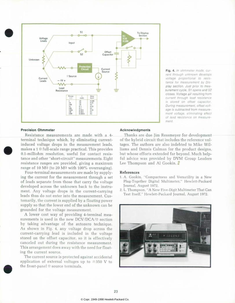
Voltage Leads
To Display Section
Unknown
Current Leads
F i g . 4 . I n o h m m e t e r m o d e , c u r r e n t t h r o u g h u n k n o w n d e v e l o p s v o l t a g e p r o p o r t i o n a l t o r e s i s t a n c e l o r m e a s u r e m e n t b y D i s p l a y s e c t i o n . J u s t p r i o r t o m e a surement cyc le , S1 opens and S2 c loses. Vol tage AV resul t ing f rom c u r r e n t t h r o u g h l e a d r e s i s t a n c e i s s t o r e d o n o f f s e t c a p a c i t o r . Dur ing measurement , o f f se t vo l t age i s sub t rac ted f r om measu re men t vo l t age , e l im ina t i ng e f f ec t o f l e a d r e s i s t a n c e o n m e a s u r e ment.
Precis ion Ohmmeter Resistance measurements are made with a 4-
terminal technique which, by eliminating current- induced voltage drops in the measurement leads, makes a 1 0 full-scale range practical. This provides 0.1-milliohm resolution, useful for contact resis tance and other "short-circuit" measurements. Eight resistance ranges are provided, giving a maximum range of 10 MO (to 20 MO with 100% overranging).
Four-terminal measurements are made by supply ing the current for the measurement through a set of leads separate from those that carry the voltage developed across the unknown back to the instru ment. Any voltage drops in the current-carrying leads thus do not enter into the measurement. Cus tomarily, the current is supplied by a floating power supply so that the lower end of the unknown can be grounded for the voltage measurement.
A lower cost way of providing 4-terminal mea surements is used in the new DCV/DCA/O section by taking advantage of the autozero technique. As shown in Fig. 4, any voltage drop across the current-carrying lead is included in the voltage stored on the offset capacitor, so it is effectively canceled out during the resistance measurement. This arrangement does away with the need for float ing the current source.
The current source is protected against accidental application of external voltages up to ±350 V to the front-panel 0 source terminals.
Acknowledgments Thanks are due }im Ressmeyer for development
of the hybrid circuit that includes the reference vol tages. The authors are also indebted to Mike Wil liams and Dennis Colman for the product designs, but whose efforts extended far beyond. Much help ful advice was provided by DVM Group Leaders Lee Thompson and Al Gookin. ff
References 1. A. Gookin, "Compactness and Versatility in a New
Plug-Together Digital Multimeter," Hewlett-Packard Journal, August 1972.
2. L. Thompson, "A New Five-Digit Multimeter That Can Test Itself," Hewlett-Packard Journal, August 1972.
23
© Copr. 1949-1998 Hewlett-Packard Co.

SPECIFICATIONS H P M o d e l 3 4 7 0 3 A D C V / D C A / M e t e r ( W i t h e i t h e r M o d e l 3 4 7 4 0 A A 1 ' ! - d i g i t
o r M o d e l 3 4 7 5 0 A 5 ' ? - d i g i t D i s p l a y S e c t i o n s . )
D C V o l t a g e R A N G E S : ~ 1 0 m V t o " i k V i n d e c a d e s t e p s , a u t o o r m a n u a l . O V E R R A N G I N G : 1 K V r a n g e 2 0 % A l l o l h e r s : 1 0 0 % . A C C U R A C Y : ( 3 0 d a y * . 2 3 ' C Â ± 5 ' C ) :
C O M M O N M O D E R E J E C T I O N : > V O d B N O R M A L M O D E R E J E C T I O N : > 6 0 d B
ACCURACY (30 day» . 23 'C ± 5 *C) :
D C C u r r e n t R A N G E S : r 1 U A t o - 1 0 0 m A i n 6 d e c a d e s l e p t , a u t o o r m a n u a l O V E R R A N G I N G : 1 0 0 % o n a l l r a n g e s A C C U R A C Y ( 3 0 d a y a , 2 3 ' C * 5 * C ) :
W i t h 3 4 7 4 0 A  ± ( 0 0 5 % ••ding  ± 0 0 3 %
100 Q I O C l O k Q 1 M Q
= ( 0 . 0 5 % o l r e a d i n g
- 0 0 1 % oà rano.)
 ± ( 0 1 2 % read ing
 ± 0 0 1 %
W i t h 3 4 7 5 0 * Â ± { 0 0 4 5 %
R A N G E
With 34 740 A ( d i s p l a y s u p
t o 1 9 9 9 9 )
W i t h 3 4 7 5 0 A ( d i s p l a y s u p to 1999991
10 mV
r ( 0 0 3 % o f r e a d i n g
 ± 0 0 3 % o f range )
J-10025», o f r e a d i n g r O 025*1, o f r a n g e i ( lest d ig i t
i s b lanked !
1 0 0 m V I V 1 0 V 1 0 0 V 1 k V
= { 0 0 3 % o f r e a d i n g  ± ( 0 0 4 % o f r e a d i n g
 ± 0 . 0 1 %  ± 0 0 2 % o l r a n g e ) o f r a n g e )
: 1 0 0 2 5 % o f r e a d i n g  ± ( 0 . 0 3 5 % o f r e a d i n g
- 0 0 0 4 % * o 0 1 % o l r a n g e ) of range i
1 0 * A 1 0 0 ^ A 1 m A 1 0 m A
 ± ( 0 0 8 % o f r e a d i n g - 0 0 3 % o f r a n g e )
 ± ( 0 0 7 5 % o l r e a d i n g ±0 025% Ol range)
 ± ( 0 . 2 7 % o l r e a d i n g [  ± 0 . 0 3 % o f r a n g  » )
± (0 ^7% of read ing  ± 0 0 2 5 % o f r a n g e )
 ± ( 0 0 4 5 %  ± ( 0 . 1 2 % o f r e a d i n g o l r e a d i n g
 ± 0 0 0 5 %  ± 0 0 0 4 %
I N P U T R E S I S T A N C E :
I N P U T R E S I S T A N C E :
( M e i e r a n d D i s p l a y s e c t i o n s t o g e t h e r ) O P E R A T I N G T E M P E R A T U R E : 0 t o 5 0 ' C POWEi
O h m s R A N G E S : 1 ' . . ' t o 1 0 M ' . ; m 8 d e c a d e s t e p s , a u t o O V E R R A N G E : i O O % o n a l l r a n g e s .
• ' 8 7 VA D I M E N S I O N S : 6 < < i n W x 3 ' . | , n H  « 9 V t i n . 0 ( 1 6 0 x ! W E I G H T : 5 l b . ( 2 , 2 6 k g ) P R I C E S I N U . S . A . : 3 4 7 0 3 A D C V / D C A / : ; M e i e r , $ 5 5 0
3 4 7 5 0 A 5 ' Â ¡ - d i g i t D i s p l a y . J 5 5 0
M A N U F A C T U R
A r t h u r J . D u m o n t ( R I G H T ) Ar t Dumont was an e lec t ron ic techn ic ian wi th the U.S. Navy, then lef t af ter 5 years to work as a tech wr i ter and cus tomer eng ineer be fore go ing on to co l lege (BSEE and MSEE, Univers i ty o f Wyoming, 1970) . Then i t was HP and the 3470 Measurement Sys tem, inc lud ing the 34750A Dig i ta l D isp lay .
Ar t and h is fami ly ( three chi ldren ages 2, to 5) , en joy l iv ing near a lake where Art keeps and sai ls a boat .
S t e p h e n B . V e n z k e ( L E F T ) Join ing HP in 1965, Steve Venzke in i t ia l ly worked as a c i rcu i t des igner ( funct ion generators) and as a product ion eng ineer . Later , he worked on the 3320 /30 -A /B Syn thes ize rs and then the 34703A DCV/DCA Meter p lug-on . He ho lds a BSEE degree f rom the Univers i ty of Minnesota and earned a MSEE at Co lorado Sta te under the HP Honors Co-op program.
Marr ied, but wi th no youngsters, Steve works wi th church-sponsored youth act iv i t ies , as wel l as en joy ing the Co lorado outdoors ( f i sh ing , backpack ing, e tc . ) .
R e i d J . G a r d n e r ( C E N T E R ) Reid Gardner jo ined HP in 1963 af ter tak ing h is MSEE at Utah State. He worked on distor t ion analyzers, then became pro ject leader for the 400E AC Vol tmeters. Next he started up the Loveland Divis ion 1C faci l i t ies, then returned to the lab as project leader on the 3431 A D ig i ta l Pane l Mete rs and on the 34703A DCV/DCA/Meter p lug-on , do ing the d ig i ta l po r t ion .
Reid l ives on a 10-acre ranch that keeps his s ix chi ldren, ages 1 Vi to 4, busy ra is ing l ivestock. Church and school act iv i t ies occupy any f ree t ime lef t .
Address Correct ion Requested: H e w l e t t - P a c k a r d C o m p a n y , 1 5 0 1 P a g e M i l l
R o a d , P a l o A l t o . C a l i f o r n i a 9 4 3 0 4
HEWLETT-PACKARD JOIUXAL
. MARCH 1973 Vo lume 24 • Number 7
Technical Information from the Laborator ies < Hewle t t -Packard Company
^ . CH-121 7 Meynn 2 G e n e v a S w i t z e r l a n d
Y o k a g a w a - H e w l e t t - P a c k a r d L t d . S h i b u y a - K u T o k y o 1 5 1 J a p a n
Editorial Director • Howard L Roberts Managing Editor • Richard P. Oolan
Contributing Editors • Ross H Snyder. L a u r e n c e O S h e r g a l i s
Art Director. Photographer • Arvid A Danielson Art Assistant • Erica R Helstrom
Administrative Services • Ruth G Palmer
B u l k R a t e U . S P o s t a g e
Paid H e w l e t t - P a c k a r d
C o m p a n y
f rR M D 2 0 9 1 0
CHANGE p lease o ld To change your address or de le te your name f rom our mai l ing l i s t p lease send us your o ld address labe l ( i t pee ls o f t ) . Send changes to Hewlett-Packard Journal. 1501 Page Mill Road. Palo Alto, California S4304 U.S.A. Allow 60 days.
© Copr. 1949-1998 Hewlett-Packard Co.