maquina roscadora / pipe threading machine / filiere ... · maquina roscadora / pipe threading...
TRANSCRIPT

MANUAL DE INSTRUCCIONESOPERATING INSTRUCTIONSMANUEL D’INSTRUCTIONS
MAQUINA ROSCADORA / PIPE THREADING MACHINE / FILIERE ELECTRIQUE
ROSCAMATIC-3 COMBI
ESPAÑOL ............................... 2
ENGLISH ................................ 8
FRANÇAIS ............................ 14
DESPIECE / SPARE PARTS DRAWING / DEPEÇAGE ...... 20
ESQUEMA ELÉCTRICO / ELEC-TRIC DIAGRAM / SCHEMA ELECTRIQUE ........................ 29
GARANTIA / GUARANTEE / GARANTIE ........................... 31

2
INSTRUCCIONES DE SEGURIDAD
¡Atención! Cuide su seguridad.
1. No utilice prendas colgantes que puedan enganchar en los elementos de rotación.2. Utilice guantes de goma en los trabajos realizados al exterior.3. Antes de poner en marcha, compruebe que tanto el cable como el enchufe se encuentran en
condiciones.4. Para cualquier manipulación sobre la máquina, asegúrese de que ha sido desconectada de la red.5. Emplee siempre los accesorios destinados a la máquina ya que sin su utilización puede resultar
lesionado.
MAQUINA ROSCADORA – 3 COMBI
Máquina roscadora adecuadamente equipada para roscar, cortar y escariar tubos de ½ ÷3" de hierro para conducción de agua, gas, etc... Además de una compacta estructura, fácil manejo y gran efi cacia de trabajo, le caracteriza el dispositivo automático de roscado mediante copia, el cual hace que la rosca obtenida sea de mejor calidad, con un menor consumo de potencia y con una mayor duración de los peines, debido a que es mucho menor el contacto de los peines sobre el tubo que los sistemas convencionales. Por lo tanto menor rozamiento y menor calentamiento de los peines.
Dispone de control automático de longitud de roscado que hace que no sea imprescindible la atención del operario, al abrirse automáticamente.
Estas máquinas han sido extensamente aplicadas en industrias de instalación y construcción.
ESPAÑOL

3
EQUIPACIÓN DE LA MÁQUINA
- 1 terraja automática de ½-2"- 1 terraja automática de 2½-3"- 3 juegos de peines (1/2-3/4"), (1-2"), (2½-3") BSPT o NPT.- 1 juego de patas.- Conexión para pedal.- 2 destornilladores mecánicos (5,5x25 y PH-2).- Juego de 3 llaves Allen (4mm, 5mm y 6mm).
IMPORTANTEPara el pedido de repuestos indique el código de éstos y el número de serie de la máquina.
CARACTERÍSTICAS TÉCNICAS
Capacidad total de la máquina 1/2÷3"Motor con condensador de arranque 750W (230V/50Hz) - (110V/60Hz) ; R.P.M.= 1/2÷2=25 / 2½ ÷3=11Dimensiones 850x500x400 mm.Peso 102 Kg.
INSTRUCCIONES DE FUNCIONAMIENTO
A) FIJACIÓN DE TUBOSA1- Abrir ambos platos e introducir el tubo a través del plato trasero y el plato delantero (por este
orden).A2- Manteniendo el extremo delantero del tubo con la mano derecha, cerrar ambos platos me-
diante una acción de golpe.
A1 A2
4
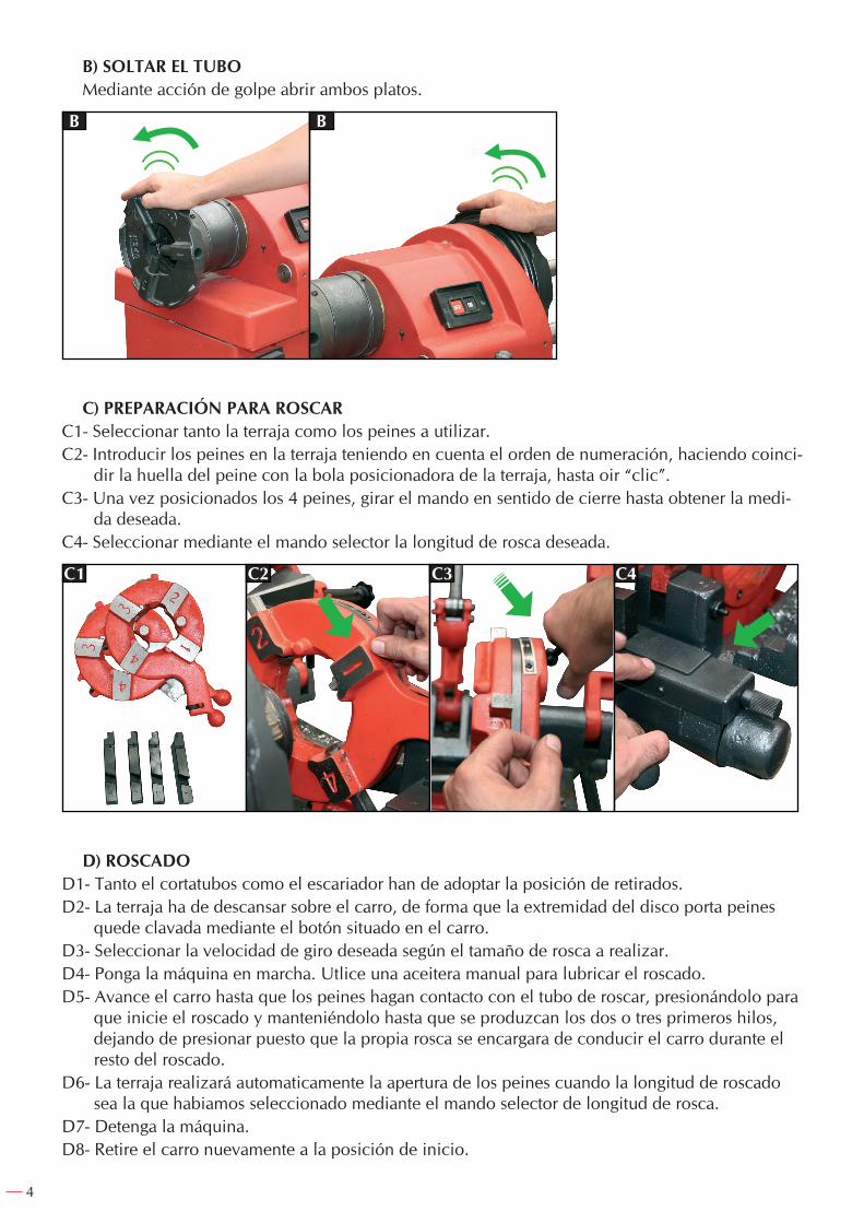
B) SOLTAR EL TUBOMediante acción de golpe abrir ambos platos.
B B
C) PREPARACIÓN PARA ROSCARC1- Seleccionar tanto la terraja como los peines a utilizar.C2- Introducir los peines en la terraja teniendo en cuenta el orden de numeración, haciendo coinci-
dir la huella del peine con la bola posicionadora de la terraja, hasta oir “clic”.C3- Una vez posicionados los 4 peines, girar el mando en sentido de cierre hasta obtener la medi-
da deseada.C4- Seleccionar mediante el mando selector la longitud de rosca deseada.
C1 C2 C3 C4
D) ROSCADOD1- Tanto el cortatubos como el escariador han de adoptar la posición de retirados.D2- La terraja ha de descansar sobre el carro, de forma que la extremidad del disco porta peines
quede clavada mediante el botón situado en el carro.D3- Seleccionar la velocidad de giro deseada según el tamaño de rosca a realizar.D4- Ponga la máquina en marcha. Utlice una aceitera manual para lubricar el roscado.D5- Avance el carro hasta que los peines hagan contacto con el tubo de roscar, presionándolo para
que inicie el roscado y manteniéndolo hasta que se produzcan los dos o tres primeros hilos, dejando de presionar puesto que la propia rosca se encargara de conducir el carro durante el resto del roscado.
D6- La terraja realizará automaticamente la apertura de los peines cuando la longitud de roscado sea la que habiamos seleccionado mediante el mando selector de longitud de rosca.
D7- Detenga la máquina.D8- Retire el carro nuevamente a la posición de inicio.

5
D1 D2 D3
COD. 64130
COD. 64002/06
D5 D6 D7 D8
D4
CORTE Y ESCARIADO DEL TUBO
E) CORTEE1- Tanto la terraja como el escariador se situaran retirados en posición de abatidos.E2- Descender el cortatubos en la posición de trabajo, habiendo abierto sufi ciente para que el cor-
tatubos descanse en el carro sin que tropiece el tubo a cortar. Trasladar el carro para situar el corte en el lugar deseado del tubo.E3- Realizar el corte presionando mediante el mando en cada una de las vueltas hasta que el tubo
haya sido cortado.
NOTA: cuide que la presión ejercida por la cuchilla para el corte no sea excesiva, ya que puede causar la malformación del tubo o rotura de la cuchilla debido a las imperfecciones del tubo.
E1 E2 E3
6
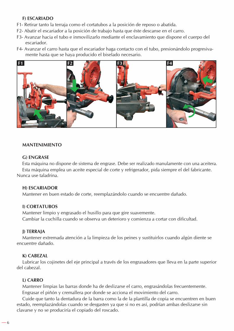
F) ESCARIADOF1- Retirar tanto la terraja como el cortatubos a la posición de reposo o abatida.F2- Abatir el escariador a la posición de trabajo hasta que éste descanse en el carro.F3- Avanzar hacia el tubo e inmovilizarlo mediante el enclavamiento que dispone el cuerpo del
escariador.F4- Avanzar el carro hasta que el escariador haga contacto con el tubo, presionándolo progresiva-
mente hasta que se haya producido el biselado necesario.
F1 F2 F3 F4
MANTENIMIENTO
G) ENGRASEEsta máquina no dispone de sistema de engrase. Debe ser realizado manulamente con una aceitera.Esta máquina emplea un aceite especial de corte y refrigerador, pida siempre el del fabricante.
Nunca use taladrina.
H) ESCARIADORMantener en buen estado de corte, reemplazándolo cuando se encuentre dañado.
I) CORTATUBOSMantener limpio y engrasado el husillo para que gire suavemente.Cambiar la cuchilla cuando se observa un deterioro y comienza a cortar con dificultad.
J) TERRAJAMantener extremada atención a la limpieza de los peines y sustituirlos cuando algún diente se
encuentre dañado.
K) CABEZALLubricar los cojinetes del eje principal a través de los engrasadores que lleva en la parte superior
del cabezal.
L) CARROMantener limpias las barras donde ha de deslizarse el carro, engrasándolas frecuentemente.Engrasar el piñón y cremallera por donde se acciona el movimiento del carro.Cuide que tanto la dentadura de la barra como la de la plantilla de copia se encuentren en buen
estado, reemplazándolas cuando se desgasten ya que si no es así, podrían ambas deslizarse sin clavarse y no se produciría el copiado del roscado.

7
M) PLATO DE ARRASTREMantenga limpias las garras para que éstas queden oscilantes y no bloqueadas.Reemplace las bocas de agarre cuando su dentadura esté dañada o desgastada, no realizando co-
rrectamente la retención del giro del tubo.
N) MOTORTenga en cuenta que este motor dispone de un condensador de arranque que deben mantener
limpio y seco, sustituyéndolo cuando sea necesario. Este va alojado al lado del motor.
RANURADOEn caso de querer ranurar con esta máquina, se debe comprar el complemento ranurador código
60185, con capacidad para ranurar tubos entre 1.1/4" y 12".
NOTAS
¡IMPORTANTE!
El fabricante no se responsabiliza de los daños o mal funcionamiento de la máquina en caso de que no se use correctamente o se haya utilizado para trabajos para los que no está diseñada.
Para pedir cualquier repuesto, mirar en el dibujo de despiece el número de la pieza deseada.
GARANTÍA
El fabricante garantiza al comprador de ésta máquina la garantía total durante 12 meses de las piezas con defectos de fabricación.
Esta garantía no cubre aquellas piezas que por su uso normal tienen un desgaste.
Nota: para obtener la validez de la garantía, es absolutamente imprescindible que complete y remita al fabricante el documento de “CERTIFICADO DE GARANTIA”, dentro de los siete dias a partir de la fecha de compra.

8
SAFETY INSTRUCTIONS
Attention! Be careful.
1. Do not wear loose clothing. They could be caught by moving parts of the machine.2. For outdoor work, rubber gloves must be worn.3. Before starting up the machine, check that the electric cable and switch are in optimum
condition.4. Before carrying out any maintenance work or change of accesories, disconnect the machine
from the mains.5. Always use the machine´s indicicated accesories because if you don´t, it could lead to risk of
personal injury.
THREADING MACHINES – 3 COMBI
This is suitable for threading, cutting and reaming ½ ÷3" water, electricity and gas pipes. Besi-des having compact structure, simple operation and higt efi ciency. It is characterized by an auto-matic profi ling device that assures a higher quality thread, less power consumption and long life of dies because the presure of the dies on the pipe is smaller than in the conventional systems.
It also has an automatic control of the thread length and that means that is not essential the ope-rator attention. Automatic opening.
Theese threading machines have been widely applied in installing and building industries.
ENGLISH

9
EQUIPMENT
- 1 automatic die head ½-2"- 1 automatic die head 2½-3"- 3 set of dies (1/2-3/4"), (1-2"), (2½-3") BSPT or NPT.- 1 set of legs.- Conection for foot pedal- 2 screwdriver (5,5x25 and PH-2).- Set of 3 Allen keys (4mm, 5mm and 6mm).
IMPORTANTWhen ordering spare parts please indicate its code number and the serial number of the machine.
TECHNICAL SPECIFICATIONS
Total capacity 1/2÷3"Condenser motor 750W (230V/50Hz) - (110V/60Hz) ; R.P.M.= 1/2÷2=25 / 2½ ÷3=11Size 850x500x400 mm.Weight 102 Kg.
OPERATION GUIDE
A) SETTING THE PIPEA1- Open both chucks and insert the pipe through the rear chuck side and the front chuck (in this
order).
A2- Holding the right end of the pipe in your right hand, lock both chucks with a knocking movement.
A1 A2

10
B) LOOSE THE PIPEB- A sharp jerk will release the pipe.
B B
C) PREPARATION FOR THREADINGC1- Select the correct die head and dies as required.C2- Insert the set of dies in the die head as numbered and make the die thread coincide with the
positioning ball of the die head, until a “klick” sounds.C3- Once the dies are positioned, turn the lever nut to lock until you get the desired measure.C4- Set the thread length desired by means of the dial.
C1 C2 C3 C4
D) THREADINGD1- Raise cutter and reamer out of the way.D2- Lower the die head to the carriage in such a way that the extremity of die head body is locked
by the carriage buttom.D3- Set the speed change lever for the size indicated.D4- Switch on the machine. Use an oiler to lubricate the threading.D5- Advance the carriage until the dies engage the pipe pressing it to start the threading and kee-
ping it until 2 threads are produced, releasing after because the thread itself would drive the carriage during the rest of the threading.
D6- The die head will automatically open the dies when the threading length is the selected by the dial threading length.
D7- Stop the machine.D8- Retract carriage to the initial position.

11
D1 D2 D3
COD. 64130
COD. 64002/06
D5 D6 D7 D8
D4
CUTTING AND REAMING
E) CUTTINGE1- Raise reamer and die head out of the pipe.E2- Lower the cutter to work position and by turning cutter handle open up cutter guide wider than
the width of the pipe. Move carriage to position where pipe is to be cut.E3- Cut the pipe turning the cutter handle in each turn of the pipe until cut is completed.
NOTE: take care that the pressure made by the cutting blade isn’t excessive. Due to pipe defects it can cause pipe deformity or bursts in the cutting blade.
E1 E2 E3

12
F) REAMINGF1- Raise die head and cutter out of the way.F2- Lower reaamer to work position onto the carriage.F3- Feed the reamer into the pipe and lock it by the reamer interlock.F4- Move the carriage until the reamer makes contact to the pipe, pressing it stepwise until the
bevel is completed.
F1 F2 F3 F4
MAINTENANCE
G) LUBRICATIONThis machine doesn´t have lubrication system. Use always an oiler to lubricate the operation.This machine uses a special oil as cooling agent for threading, ask for maker’s oil. Never use
cutting water.
H) REAMERKeep cutting in good condition and replace it when damaged.
I) CUTTERClean and lubricate the feed screw so that turns softly.Change the cutter wheel when damaged and it cuts with difficulty
J) DIE HEADTake great care with the dies cleaning and replace them when damaged teeth.
K) HEAD STOCKLubricate hollow spindle bearings through the two grease nipples in the head stock.
L) CARRIAGEClean and lubricate frequently the bars of the carriage.Lubricate the gear and rack that make the carriage drive.Be carefull that bar and profiling board teeth are in good condition, replace them when they will
not lock and the profiling will not be produced.

13
M) HAMMER CHUCKKeep the chuck-jaws clean so that they swing and they are not blocked.Replace the chuck-jaws when their theeth is damaged or worn out and the don’t make correctly
the pipe turning retention.
N) MOTORTake into account that this motor has a condenser that must be kept clean and dry, replace it
when necessary. This is placed beside the motor.
GROOVINGThis machine allows the user to groove pipes buying hydraulic roll groover, code 60185. Its
capacity is 1,1/4"-12".
NOTES
IMPORTANT!
The maker will not take responsibility for damage or malfunction as a result of the Testing Pump being incorrectly used or, applied for a purpose for which it was not intended.
For ordering spare parts, please refer to the Spare Parts Drawing and note the needed number.
GUARANTEE
The maker guarantees to the machine owner 12 months against any manifacture defect.This guaranteee do not cover the parts wich are consumables.
Note: to apply the guarantee its necesary to send the “GUARANTEE CERTIFICATE” duly filled within one week after purchased the machine to the maker.

14
INSTRUCTIONS DE SECURITE
Attention! Soyez prudent.
1. N´utilisez pas des vêtements amples Ils pourraient être entrainés dans les parties mobiles de la machine.
2. Utilisez des gants de travail en caoutchouc, lors de travaux en extérieur.3. Avant de démarrer la machine, vérifi ez le bon état du câble d´alimentation électrique et de
l´interrupteur.4. Déconnectez la machine du secteur, avant toute intervention d´entretien de la machine ou de
changement d´accesoire.5. N´utilisez que des accesoires destinés exactement á la machine, afi n d´eviter tout risque de
blessure corporelle.
MACHINE A FILETER – 3 COMBI
Filière équipée pour le fi ltage, la coupe et l’alésage de tubes en fer de ¼÷2" pour l’eau, le gaz,etc …Machine compacte, maniable et d’une grande effi cacité, qui se caractérise par son dispositif auto-
matique de fi letage moyennant un reproducteur, ce qui permet d’obtenir un fi let de meilleure qua-lité avec une consommation de puissance moindre et avec une durée des peignes supérieure, du au fait que le contact des peignes sur le tube est moins important qu’avec les systèmes conventionnels. Par conséquent, il y a moins de frôlement et d’échauffement des peignes.
Elle dispose d’un contrôle automatique de la longueur de fi letage qui fait que l’attention d’un opérateur n’est pas indispensable, étant donnée qu’elle s’ouvre automatiquement.
Ces machines ont été utilisées par extension pour l’installation et la construction industrielles.
FRANÇAIS
15
EQUIPEMENT
- 1 tête de filière automatique ½-2"- 1 tête de filière automatique 2½-3"- 3 sets de peignes (1/2-3/4"), (1-2"), (2½-3") BSPT o NPT.- 1 set de pieds.- Branchement de pédale.- 2 tournevis mécanicien (5,5x25 et PH-2).- Set de 3 clés héxagonales (4mm, 5mm et 6mm).
IMPORTANTPour la commande de piéces détachées, indiquer la référence et le numéro de série de la machine.
CARACTERISTIQUES TECHNIQUES
Capacité totale 1/2÷3"Condenser motor 750W (230V/50Hz) - (110V/60Hz) ; R.P.M.= 1/2÷2=25 / 2½ ÷3=11Dimension 850x500x400 mm.Poids 102 Kg.
GUIDE D’UTILISATION
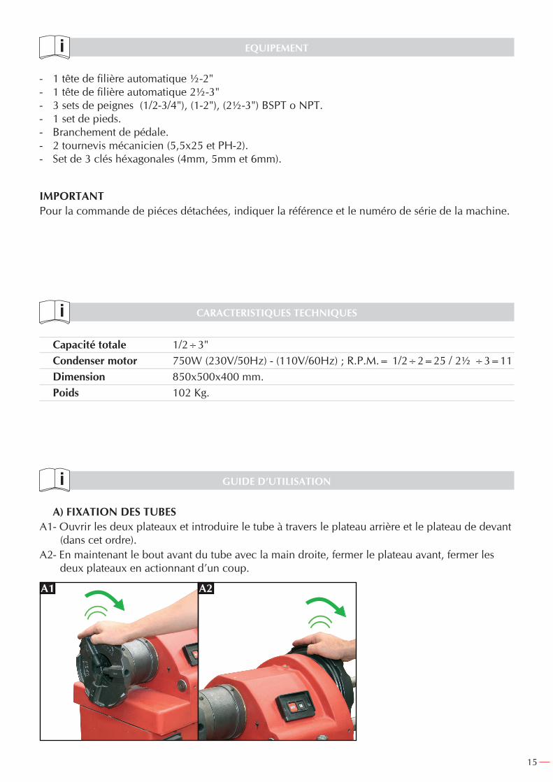
A) FIXATION DES TUBESA1- Ouvrir les deux plateaux et introduire le tube à travers le plateau arrière et le plateau de devant
(dans cet ordre).A2- En maintenant le bout avant du tube avec la main droite, fermer le plateau avant, fermer les
deux plateaux en actionnant d’un coup.
A1 A2

16
B) SORTIR LE TUYAUB- En agissant d’un coup sur le disque extérieur.
B B
C) PREPARATION POUR FILETERC1- Choisir suivant le cas les têtes ou les peignes à utiliser.C2- Introduire les peignes sur la filière en suivant l’ordre de numérotation, et en faisant coïncider
l’empreinte du peigne avec la boule de positionnement de la filière, jusqu’à entendre un “clic“.C3- Une fois positionnés les 4 peignes, tourner la manette en sens de serrage, jusqu’à obtenir la
mesure désirée, en la fixant dans cette position.C4- Sélectionner grâce à la mannette sélection la longueur de filetage désirée.
C1 C2 C3 C4
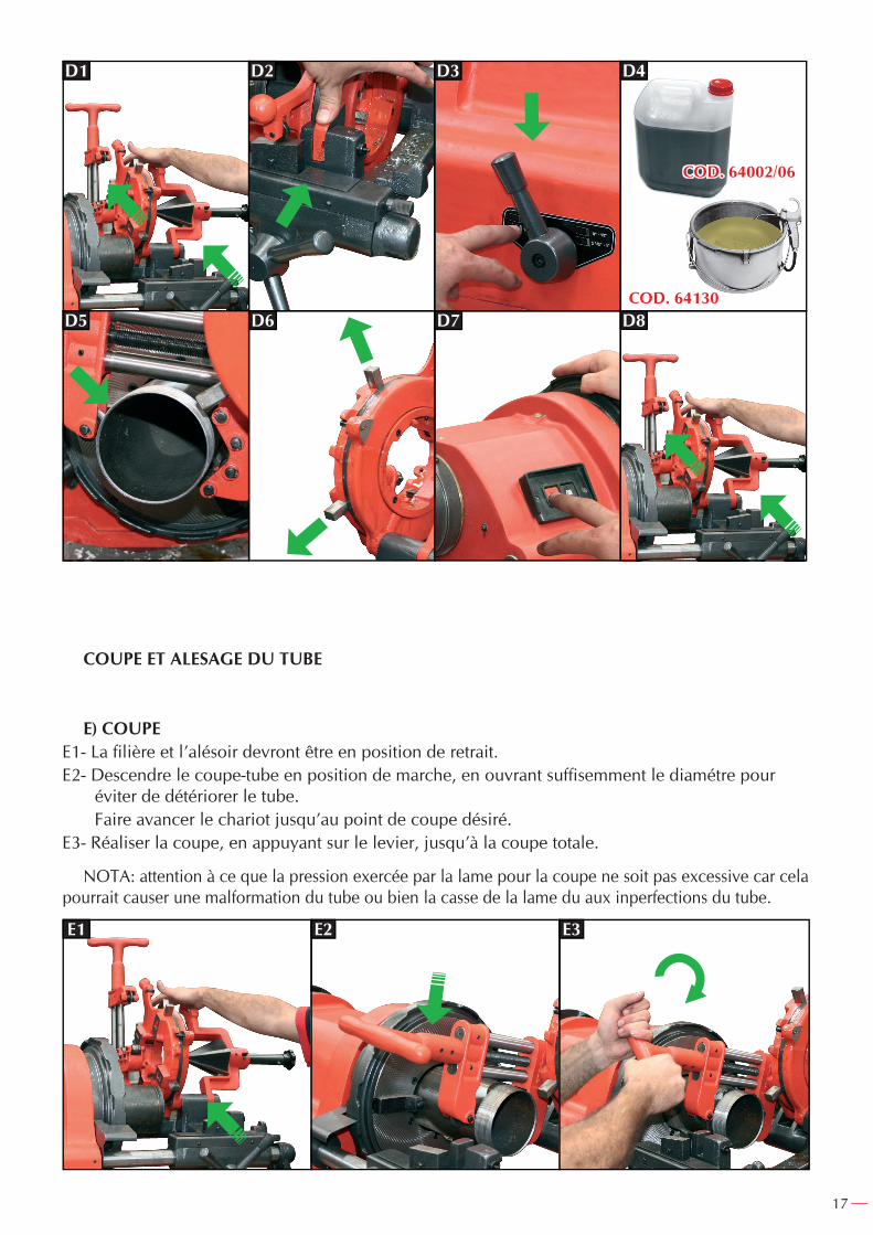
D) FILETAGED1- Le coupe-tube et l’alésoir doivent être en position de retrait.D2- La tête de filière doit être reposée sur le chariot, de telle façon que l’extrémité du disque porte
peignes reste fixée par le bouton situé sur le chariot.D3- Sélectionner la vitesse de tour souhaitée selon la taille du filet à réaliser.D4- Mettez la machine en marche. Utilisez un huilier manuel pour lubrifier le filetage.D5- Avancer le chariot, jusqu’à ce que les peignes soient en contact avec le tube à fileter, en appuyant
pour initier les premiers files, après quoi les peignes guideront eux même le tube, jusqu’à la fin.D6- La tête de filière réalisera automatiquement l’ouverture des peignes quand la longueur de fileta-
ge sera conforme à celle désirée grâce à la mannette sélection de longueur du filet.D7- Stopper la machine.D8- Remettre le chariot à son positionnement initial pour répéter l’opération.
17
D1 D2 D3
COD. 64130
COD. 64002/06
D5 D6 D7 D8
D4
COUPE ET ALESAGE DU TUBE
E) COUPEE1- La fi lière et l’alésoir devront être en position de retrait.E2- Descendre le coupe-tube en position de marche, en ouvrant suffi semment le diamétre pour
éviter de détériorer le tube. Faire avancer le chariot jusqu’au point de coupe désiré.E3- Réaliser la coupe, en appuyant sur le levier, jusqu’à la coupe totale.
NOTA: attention à ce que la pression exercée par la lame pour la coupe ne soit pas excessive car cela pourrait causer une malformation du tube ou bien la casse de la lame du aux inperfections du tube.
E1 E2 E3

18
F) ALESAGEF1- Retirer aussi bien la tête de filière que le coupe tube (position arrière).F2- Rabattre l’alésoir en position de travail jusqu’à qu’il soit sur le chariot.F3- Avancer jusqu’au tube, l’immobiliser à l’aide d’une fixation située sur le corps de l’alésoir.F4- Avancer le chariot jusqu’à ce que l’alésoir fasse contact avec le tube, en appuyant dessus pro-
gressivement jusqu’à obtenir le chanfrein désiré.
F1 F2 F3 F4
MAINTENANCE
G) LUBRIFICATIONCette machine ne dispose pas de système de graissage. Il doit être réalisé manuellement avec un
huilier.Cette machine utilise une huile spéciale, demandez toujours celle du fabricant. Ne jamais utili-
ser de liquide de refroidissement.
H) ALESOIRMaintenir en bon état, en le remplaçant quand il est détérioré.
I) COUPE-TUBEMaintenir propre et graissée la broche pour une rotation douce.Changer le couteau quand on observe une détérioration et quand il commence à couper mal.
J) FILIEREMaintenir les peignes très propres et les changer quand des dents sont cassées.
K) SUPPORTLubrifier les coussinets de l’axe principal à l’aide des graisseurs de la partie supérieure du support.
L) CHARIOTTenir propre les rails du chariot.Graisser le pignon et la crémaillère qui actionnent le mouvement du chariot.Attention à ce que les dents de la barre et celles du modèle du reproducteur soient en bon état
et les remplacer quand elles sont usées car si ce n’est pas le cas, les deux pourraient glisser sans se

19
fixer et le reproducteur du filetage ne se feraient pas.M) PLATEAU D’AMARRAGEGarder propre les fixations pour qu’elles restent oscillantes et non bloquées.Remplacer les bouches de fixation quand la denture est entamée ou détériorée, ne pouvant réali-
ser correctement la rétention du tour de tube.
N) MOTEURA noter que ce moteur dispose d’un condensateur de démarrage qui doit être maintenu propre et
sec, et remplacé dés que nécessaire. Celui-ci est placé à côté du moteur.
RAINUREDans le cas où vous souhaiteriez rainurer avec cette machine, il faut acheter le complément
pour rainurer code 60185 avec une capacité pour rainurer les tubes comprise entre1.1/4" et 12".
NOTES
IMPORTANT!
Le fabricant ne se responsabilise pas des détériorations ou du mauvais fonctionnement de la machine dans le cas d’une mauvaise utilisation ou suite à des usages pour lesquels elle n’est pas concue.
Pour commander les pièces de rechange, regarder le descriptif et le numéro de pièce désiré.
GARANTIE
Le fabricant donne une garantie de 12 mois à l’acquéreur de cette machine, pour les pièces avec un défaut de fabrication.
La garantie ne s’applique pas aux pièces d’usure normale.
Note : pour obtenir la validité de la garantie, il est obligatoire de compléter et de retourner au fabricant, le document ‘’CERTIFICAT DE GARANTIE’’ dans les 7 jours d’acquisition de la machine.

20
DESPIECE / SPARE PARTS DRAWING / DEPEÇAGE
DENOMINACION DESCRIPTION DESCRIPTION ITEM COD CANT / QTY / QTÉ
TAPACABEZAL
INTERRUPTORTORNILLO M.4x20
TAPATORNILLO M.4x10BARRA TRASERA
BARRA DELANTERAMANILLA CAMBIO
VELOCIDADBANCADA
PATASENCHUFE PEDAL
PEDAL
123456789
1011+12
825408258382106825848258582586825378255782587
82588821238071481603
111111111
141
(Optional)
COVERHEAD STOCK
SWITCHSCREW M.4x20
COVERSCREW M.4x10
REAR BARFRONT BAR
SPEED CHANGEHANDLE
BODYLEGS
PEDAL PLUGPEDAL
COUVERCLETÊTE
INTERRUPTEURVIS M.4x20
COUVERCLEVIS M.4x10
BARRE ARRIÈREBARRE AVANT
MANETTE CHANGE-MENT DE VITESSE
BANCPATTES
PRISE PEDALEPEDALE
CUERPO PRINCIPAL / MAIN BODY / CORPS PRINCIPAL

21
CARRO / CARRIAGE / CHARIOT
DENOMINACION DESCRIPTION DESCRIPTION ITEM COD CANT / QTY / QTÉ
PLACA SUPERIOR COPIA
CUBIERTA DE COPIA
TACO DERECHO EJE COPIAMUELLECOPIA
EJE GUIA COPIA
TACO IZQUIERDO EJE COPIA
MUELLEVOLANTE DEL CARRO
PASADOREJE DEL VOLANTE
CHAVETAENGRANAJE VOLANTEESPÁRRAGO M.5x20
ARANDELACARRO
VÁLVULA
TUBO DE ACEITEMETÁLICOPUNTERAMUELLE
EJEAGARRADERO
1
3
4
567
8
9101112131415161718192021222324
25262728
82363
82365
82367
823688237082371
82372
823738236282374823758237682366823778237882369
82116
82380
82381823828238382384
1
1
1
211
1
211111111
1
1
1111
COVER PLATE
PROFILING BOARD COVER
RIGHT SHAFT BAFFLE
SPRINGPROFILING BOARD
COPY GUIDING AXLE
LEFT SHAFT BAFFLE
SPRINGSTEERPIN
STEER AXLESHAFT-KEYSTEER GEAR
STUD M.5x20WASHER
CARRIAGE
VALVE
OIL PIPE
TIPSPRING
AXLEBOLT-KNOB
PLAQUE SUPPORT REPRODUCTEURCOUVERCLE DUREPRODUCTEUR
TAQUET DROIT AXE REPRODUCTEUR
RESSORTREPRODUCTEUR
AXE GUIDADE REPRODUCTEURTAQUET GAUCHE
AXE REPRODUCTEURRESSORT
VOLANT DU CHARIOTGOUJON
AXE DU VOLANTCLAVETTE
ENGRENAGE VOLANTCLOU
RONDELLECHARIOT
VALVE
TUBE D’HUILLEMETALLIQUE
BOUTRESSORT
AXEPOIGNÉE
22
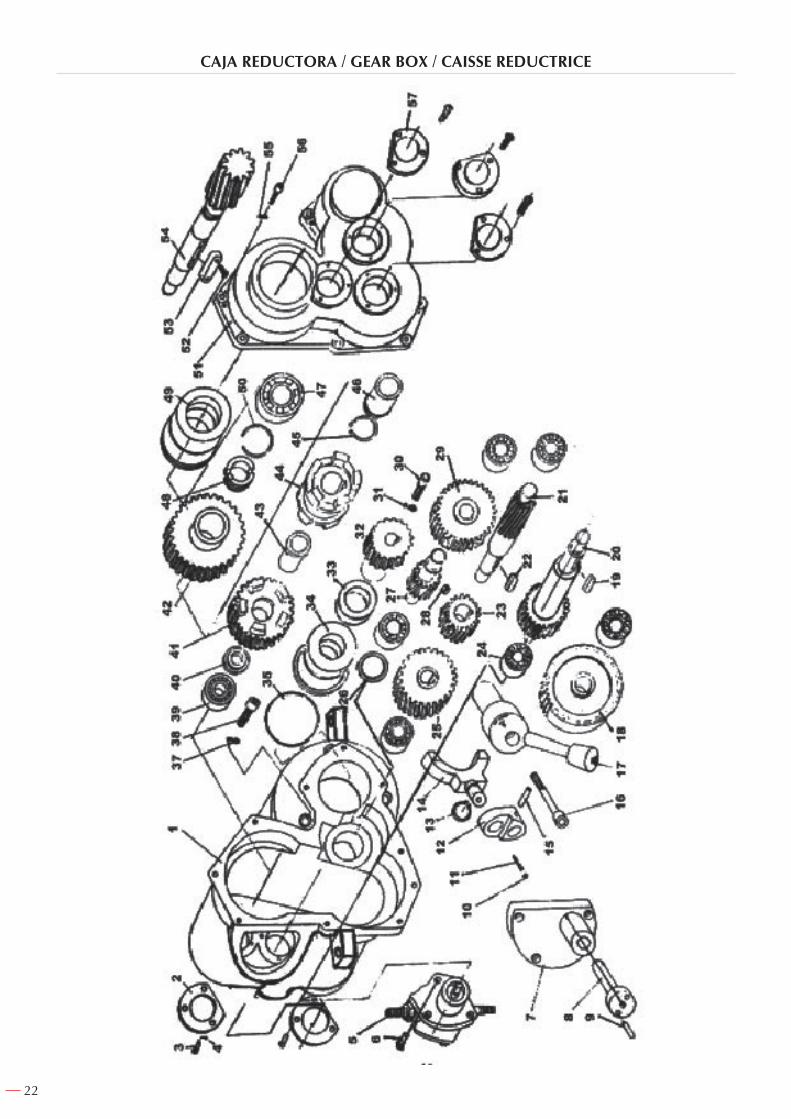
CAJA REDUCTORA / GEAR BOX / CAISSE REDUCTRICE

23
DENOMINACION DESCRIPTION DESCRIPTION ITEM COD CANT / QTY / QTÉ
CUERPO CAJA REDUCTORATAPA
TORNILLO M.5x12ARANDELA M.5
CONJ. BOMBA DE ACEITETORNILLO M.6x15
TAPA DE HORQUILLAEJE
PASADOR Ø5x20BOLA Ø6MUELLE
SOPORTEANILLA Ø5
HORQUILLAPASADOR Ø5x30
TORNILLO M.8x65MANILLA CAMBIO VELOCIDAD
ENGRANAJECHAVETA 5x5x20EJE ENGRANAJEEJE ENGRANAJE
CHAVETA 5x5x20ENGRANAJE
RODAMIENTO 102ENGRANAJECASQUILLO
EJE-ENGRANAJECHAVETA 5x5x10
ENGRANAJETORNILLO M.6x20
ARANDELA M.6ENGRANAJE MOTOR
CASQUILLO GUIACASQUILLO
JUNTA TORICA Ø65ARANDELA M.8
TORNILLO M.8x20RODAMIENTO 202
ARANDELAENGRANAJEENGRANAJECASQUILLOEMBRAGUEANILLA E-25CASQUILLO
RODAMIENTOCASQUILLOCASQUILLO
ANILLA SEEGERTAPA CAJA REDUCTORA
TORNILLO M.4x12CHAVETA Ø8x40
ENGRANAJEARANDELA M.5
TORNILLO M.5x18TAPA
CONJUNTO CAJA REDUCTORAMOTOR A 230VMOTOR A 110VCONDENSADOR
123456789
1011121314151617181920212223242526272829303132333435373839404142434445464748495051525354555657
823858238682387823888216782390823918239282393823948239582396823978239882399824008240182402824038240482405824068240782408824098241082411824128241382414824158241682417824188241982421824228242382424824258242682427824288242982430824318243282433824348243582436824378243882439824408244282441821708217182173
11332311211111111111111111111111111111111111111111111771
GEAR HOUSINGCOVER
SCREW M.5x12SPRING WASHER M.5
OIL PUMP SETSCREW M.6x15FORK COVER
AXLEROUND PIN Ø5x20
STEEL BALL Ø6SPRING
FORK SUPPORTBAFFLE RING Ø5
FORKROUND PIN Ø5x30
SCREW M.8x65SPEED SWITCHER HANDLE
GEARFLAT PIN 5x5x20
LONG GEAR SHAFTGEAR SHAFT
FLAT PIN 5x5x20GEAR
BEARING 102GEARRING
GEAR-AXLEFLAT PIN 5x5x10
GEARSCREW M.6x20
WASHER Ø6MOTOR GEAR
GUIDING RINGSEAL
O-RING Ø65WASHER M.8
HEX SOCKET BOLT M.8x20BEARING 202
WASHERCLUTCH GEARCLUTCH GEAR
BUSHINGCLUTCH
BAFLE RING 25BUSHINGBEARING
SHAFT RINGSPRING RINGSEEGER RING
GEAR HOUSING COVERSCREW M.4x12FLAT PIN Ø8x40OUTPUT GEARWASHER M.5
SCREW M.5x18COVER
GEAR BOX SETMOTOR AT 230VMOTOR AT 110V
CONDENSER
CORPS CAISSE REDUCTRICECOUVERCLEVIS M.5x12
RONDELLE M.5ENSEMBLE POMPE À HUILE
VIS M.6x15COUVERCLE A FOURCHE
AXEGOUJON Ø5x20
BOULE Ø6RESSORTSUPPORTANNEAUFOURCHE
GOUJON Ø5x30VIS M.8x65
POIGNÉE DE CHANGEMENT DE VITESSEENGRENAGE
CLAVETTE 5x5x20AXE ENGRENAGEAXE ENGRENAGECLAVETTE 5x5x20
ENGRENAGEROULEMENT 102
ENGRENAGEBAGUE
AXE ENGRENAGECLAVETTE 5x5x10
ENGRENAGETORNILLO M.6x20
ENGRENAGE MOTEURRONDELLE M.6
BAGUE DE GUIDAGEBAGUE
JOINT TORIQUERONDELLE M.8
VISROULEMENTRONDELLE
ENGRENAGEENGRENAGE
BAGUEEMBRAYAGEANNEAU E-25
BAGUEROULEMENT
BAGUEBAGUE
ANNEAU SEEGERCOUVERCLE CAISSE REDUCTRICE
VIS M.4x12CLAVETTE Ø8x40
ENGRENAGERONDELLEVIS M.5x18
COUVERCLEENSEMBLE CAISSE REDUCTRICE
MOTEUR A 230VMOTEUR A 110VCONDENSATEUR

24
PLATO DELANTERO Y TRASERO / FRONT AND REAR CHUCK / PLATEAU AVANT ET ARRIÈRE
DENOMINACION DESCRIPTION DESCRIPTION ITEM COD CANT / QTY / QTÉ
CUERPO PLATO DELANTEROJGO. 3 GARRAS PLATO DELANTERO
JGO. 3 PORTA GARRASESPÁRRAGO M.6x20
MUELLEPUNTERA
CASQUILLO PLATO DELANTEROCASQUILLO GUIA DELANTEROCASQUILLO GUIA TRASERO
TORNILLO M.6x15CAÑA
CASQUILLO PLATO TRASEROCUERPO PLATO TRASEROJGO. 3 GARRAS PLATO TRASERO
CIRCLIPS 190ENGRANAJE
PASADOR Ø6x25CASQUILLO DE GOLPE
PLATO DELANTEROPASADOR M.6x15TORNILLO M.6x50
TAPÓN PLATO TRASEROARANDELA M.5
CONJUNTO PLATO DELANTEROCONJUNTO PLATO TRASERO
123456789
101112131415161718
19202122
824488219182450824518245282453824548245582456824578245882459824608246182462824638246482465
824668246782468824698247082471
111333111611111131
3633
FRONT CHUCK PLATEFRONT CHUCK JAWS SETFRONT JAW CARRIERS SET
HEX SOCKET SCREW M.6x20SPRING
ROLL PINFRONT CHUCK SCROLL CAM
FRONT COLLARREAR COLLARSCREW M.6x15
HOLLOW SPINDLEREAR BUSHING
REAR CHUCK PLATEREAR CHUCK JAW SET
RING 190GEAR
PIN Ø6x25HAMMER CHUCK
PIN M.6x15SCREW M.6x50
REAR CHUCK CAPWASHER M.5
FRONT CHUCK SETREAR CHUCK SET
CORPS PLATEAU AVANTJEU 3 CROCHETS PLATEAU AVANT
JEU 3 PORTE-CROCHETS CLOU M.6x20
RESSORTBOUT
BAGUE PLATEAU AVANTBAGUE DE GUIDAGE AVANTBAGUE DE GUIDAGE ARRIERE
VIS M.6x15TIGE
BAGUE PLATEAU ARRIERECORPS PLATEAU ARRIERE
JEU 3 CROCHETS PLATEAU ARRIERECIRCLIPS 190ENGRENAGE
GOUJON Ø6x25BAGUE À FRAPPERPLATEAU AVANTGOUJON M.6x15
VIS M.6x50BOUCHON PLATEAU ARRIERE
RONDELLE M.5ENSEMBLE PLATEAU AVANTENSEMBLE PLATEAU ARRIERE

25
TERRAJA (½ ÷ 2") / DIE HEAD (½ ÷ 2") / FILIERE (½ ÷ 2")
DENOMINACION DESCRIPTION DESCRIPTION ITEM COD CANT / QTY / QTÉ
CUERPO DE APOYODISCO DE LEVASEJE DE AMARRE
ARANDELAMANILLA
PASADOR Ø6x28RODILLO
PLACA INDICETORNILLO M.4x8
DISCO REGULADOREJE DE GIROBOLA Ø5/16"
MUELLETORNILLO M.6x35
CASQUILLOMUELLE
ESPARRAGO M.6x20TORNILLO M.6x20
EJE TOPECONJUNTO TERRAJA ½÷2"JUEGO PEINES ½÷¾" BSPTJUEGO PEINES 1÷2" BSPT
123456789
10111213141516171819
82474824758247682477824788247982480824818248282483824848248582486824878248882489824908249182492816046420564206
1111111111144411111
SUPPORT BODYCAM PLATEFIXING AXLE
WASHERHANDLE
PIN Ø6x28ROLLER
INDEX PLATESCREW M.4x8
ADJUSTING PLATESUPPORT AXLE
STEEL BALL Ø5/16"SPRING
SCREW M.6x35SUPPORT COLLAR
SPRINGSTUD M.6x20
SCREW M.6x20DOWEL PIN
½÷2" DIE HEAD SETDIE SET ½÷¾" BSPT
DIE SET 1-2" BSPT
CORPS DE SOUTIENDISQUE DE LEVÉEAXE D’AMARRAGE
RONDELLEPOIGNÉE
GOUJON Ø6x28ROULEAU
PLAQUE INDEXVIS M.4x8
DISQUE RÉGULATEURAXE DE ROTATION
BOULE Ø5/16"RESSORT
VIS M.6x35BAGUE
RESSORTCLOU M.6x20
VIS M.6x20AXE BUTOIR
ENSEMBLE FILIERE ½÷2"JEUX DE PEIGNES ½÷¾" BSPTJEUX DE PEIGNES 1÷2" BSPT
26
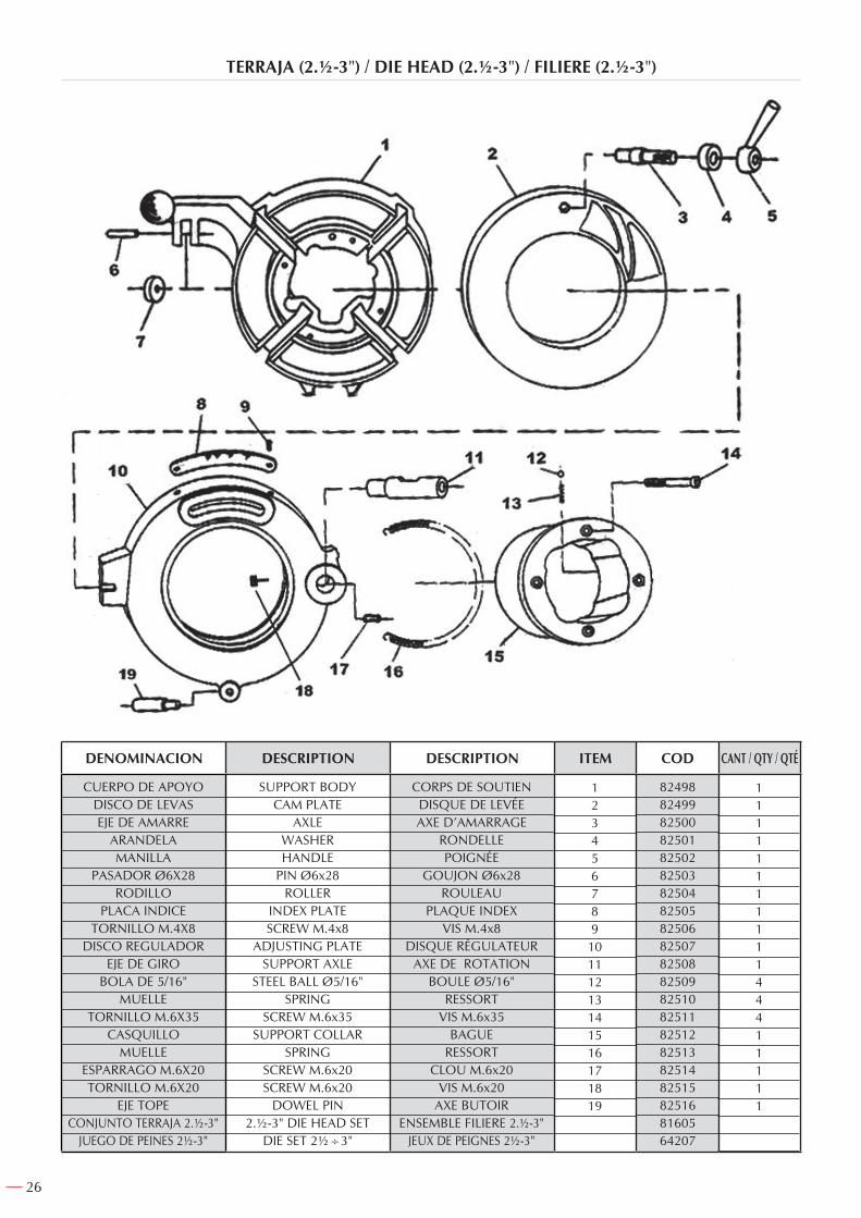
TERRAJA (2.½-3") / DIE HEAD (2.½-3") / FILIERE (2.½-3")
DENOMINACION DESCRIPTION DESCRIPTION ITEM COD CANT / QTY / QTÉ
CUERPO DE APOYODISCO DE LEVASEJE DE AMARRE
ARANDELAMANILLA
PASADOR Ø6X28RODILLO
PLACA INDICETORNILLO M.4X8
DISCO REGULADOREJE DE GIRO
BOLA DE 5/16" MUELLE
TORNILLO M.6X35CASQUILLO
MUELLEESPARRAGO M.6X20TORNILLO M.6X20
EJE TOPECONJUNTO TERRAJA 2.½-3"
JUEGO DE PEINES 2½-3"
123456789
10111213141516171819
824988249982500825018250282503825048250582506825078250882509825108251182512825138251482515825168160564207
1111111111144411111
SUPPORT BODYCAM PLATE
AXLEWASHERHANDLE
PIN Ø6x28ROLLER
INDEX PLATESCREW M.4x8
ADJUSTING PLATESUPPORT AXLE
STEEL BALL Ø5/16"SPRING
SCREW M.6x35SUPPORT COLLAR
SPRINGSCREW M.6x20SCREW M.6x20
DOWEL PIN2.½-3" DIE HEAD SET
DIE SET 2½÷3"
CORPS DE SOUTIENDISQUE DE LEVÉEAXE D’AMARRAGE
RONDELLEPOIGNÉE
GOUJON Ø6x28ROULEAU
PLAQUE INDEXVIS M.4x8
DISQUE RÉGULATEURAXE DE ROTATION
BOULE Ø5/16"RESSORT
VIS M.6x35BAGUE
RESSORTCLOU M.6x20
VIS M.6x20AXE BUTOIR
ENSEMBLE FILIERE 2.½-3"JEUX DE PEIGNES 2½-3"
27
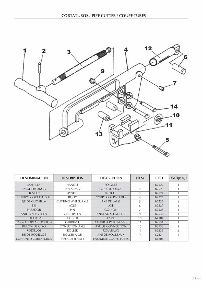
CORTATUBOS / PIPE CUTTER / COUPE-TUBES
DENOMINACION DESCRIPTION DESCRIPTION ITEM COD CANT / QTY / QTÉ
MANILLAPASADOR Ø6X25
HUSILLOCUERPO CORTATUBOS
EJE DE CUCHILLAEJE
PASADORANILLA SEEGER E-9
CUCHILLACARRO PORTA CUCHILLA
BULON DE GIRORODILLOS
EJE DE RODILLOSCONJUNTO CORTATUBOS
12345679
1011121314
8252282523825248252582526825278252882530641048253182532825338253481606
1111111311122
HANDLEPIN A.6x25
SPINDLEBODY
CUTTING WHEEL AXLEAXLEPIN
CIRCLIPS E-9CUTTER
CARRIAGECONECTION AXLE
ROLLERROLLER AXLE
PIPE CUTTER SET
POIGNÉEGOUJON Ø6x25
BROCHECORPS COUPE-TUBES
AXE DE LAMEAXE
GOUJONANNEAU SEEGER E-9
LAMECHARIOT PORTE-LAMEAXE DE CONNECTION
ROULEAUXAXE DE ROULEAUX
ENSEMBLE COUPE-TUBES

28
ESCARIADOR / REAMER / ALESOIR
DENOMINACION DESCRIPTION DESCRIPTION ITEM COD CANT / QTY / QTÉ
PASADOR Ø8x50EJE DEL ESCARIADOR
PASADOR Ø8x40EJE DE GIRO
CUERPO DEL ESCARIADORCABEZA ESCARIADOR
BOLA Ø8MUELLEPOMO
CONJUNTO ESCARIADOR
123456789
82544825458254682547825488254982550825518255281607
111111111
ROUND PIN Ø8x35SPINDLE
ROUND PIN Ø8x40AXLE
BODYREAMER HEADSTEEL BALL Ø8
SPRINGKNOB
REAMER SET
GOUJON Ø8x50AXE DE L’ALESOIRGOUJON Ø8x40
AXE DE ROTATIONCORPS DE L’ALESOIR
TETE ALESOIRBOULE Ø8RESSORT
POMMEAUENSEMBLE ALESOIR

29
ESQUEMA ELÉCTRICO / ELECTRIC DIAGRAM / SCHEMA ELECTRIQUE
ALMACENAJE Guardar en un lugar seco para evitar humedades y descargas eléctricas.STORAGE Store the threader in a dry place to avoid humidity and electric shock.
STOCKAGE Guarder dans un endroit sec pour eviter l’humidite et les décharges electriques.

30

ARTICULO / ITEM / ARTICLE: ....................................................................................................................
Nº DE SERIE / SERIE Nº / Nº SERIE: ...........................................................................................................
DISTRIBUIDOR / DISTRIBUTOR / DISTRIBUTEUR: ...................................................................................
PAIS / COUNTRY / PAYS: .............................................................................TEL.:....................................
FECHA DE VENTA / SALE DATE / DATE VENTE: ........................................................................................
NOMBRE DEL COMPRADOR / BUYER NAME / NOM DE L’ACHETEUR: ..................................................
TEL. COMPRADOR / BUYER TEL. / TEL. DE L’ACHETEUR: ........................................................................
CERTIFICADO DE GARANTIAGUARANTEE CERTIFICATECERTIFICAT DE GARANTIE
SELLO / STAMP / CACHET
EGA MASTER GARANTIZA AL COMPRADOR DE ESTA MAQUINA LA GARANTIA TOTAL (DURANTE 12 MESES), DE LAS PIEZAS CON DEFECTOS DE FABRICACION. ESTA GARANTIA NO CUBRE AQUELLAS PIEZAS QUE POR SU USO NORMAL TIENEN UN DESGASTE. PARA OBTENER LA VALIDEZ DE LA GARANTIA , ES ABSOLUTAMENTE IMPRESCINDIBLE QUE COMPLETE Y REMITA ESTE DOCUMENTO A EGA MASTER , DENTRO DE LOS SIETE DIAS A PARTIR DE LA FECHA DE COMPRA.
EGA MASTER GUARANTEES TO THE BUYER OF THIS MACHINE THE TOTAL WARRANTY (DURING 12 MONTHS), OF THE PIECES WITH MANUFACTURING FAULTS.THIS GUARANTEE DOES NOT COVER THOSE PIECES WORN OUT DUE TO A NORMAL USE. IN ORDER TO OBTAIN THE VALIDITY OF THIS WARRANTY , IT IS ABSOLUTE-LY NECESSARY TO FULFILL THIS DOCUMENT AND RESEND IT TO EGA MASTER WITHIN 7 DAYS FROM SALE DATE.
EGA MASTER GARANTIE A L’ACHETEUR DE CETTE MACHINE LA GARANTIE TOTALE (PENDANT 12 MOIS) DES PIECES AVEC DEFAUTS DE FABRICATION. CETTE GARANTIE NE COUVRE PAS LES PIECES QUE PAR UN USAGE NORMAL, SOIENT DETERIOREES. POUR OBTENIR LA VALIDITE DE LA GARANTIE, IL EST ABSOLUMENT IMPERATIF COMPLETER ET ENVOYER CE DOCUMENT EGA MASTER, DANS UN DELAI DE 7 JOURS A PARTIR DE LA DATE D’ACHAT.
EJEMPLAR PARA EGA MASTER / COPY FOR EGA MASTER / EXEMPLAIRE POUR EGA MASTER
ARTICULO / ITEM / ARTICLE: ....................................................................................................................
Nº DE SERIE / SERIE Nº / Nº SERIE: ...........................................................................................................
DISTRIBUIDOR / DISTRIBUTOR / DISTRIBUTEUR: ...................................................................................
PAIS / COUNTRY / PAYS: .............................................................................TEL.:....................................
FECHA DE VENTA / SALE DATE / DATE VENTE: ........................................................................................
NOMBRE DEL COMPRADOR / BUYER NAME / NOM DE L’ACHETEUR: ..................................................
TEL. COMPRADOR / BUYER TEL. / TEL. DE L’ACHETEUR: ........................................................................
CERTIFICADO DE GARANTIAGUARANTEE CERTIFICATECERTIFICAT DE GARANTIE
SELLO / STAMP / CACHET
EGA MASTER GARANTIZA AL COMPRADOR DE ESTA MAQUINA LA GARANTIA TOTAL (DURANTE 12 MESES), DE LAS PIEZAS CON DEFECTOS DE FABRICACION. ESTA GARANTIA NO CUBRE AQUELLAS PIEZAS QUE POR SU USO NORMAL TIENEN UN DESGASTE. PARA OBTENER LA VALIDEZ DE LA GARANTIA , ES ABSOLUTAMENTE IMPRESCINDIBLE QUE COMPLETE Y REMITA ESTE DOCUMENTO A EGA MASTER , DENTRO DE LOS SIETE DIAS A PARTIR DE LA FECHA DE COMPRA.
EGA MASTER GUARANTEES TO THE BUYER OF THIS MACHINE THE TOTAL WARRANTY (DURING 12 MONTHS), OF THE PIECES WITH MANUFACTURING FAULTS.THIS GUARANTEE DOES NOT COVER THOSE PIECES WORN OUT DUE TO A NORMAL USE. IN ORDER TO OBTAIN THE VALIDITY OF THIS WARRANTY , IT IS ABSOLUTE-LY NECESSARY TO FULFILL THIS DOCUMENT AND RESEND IT TO EGA MASTER WITHIN 7 DAYS FROM SALE DATE.
EGA MASTER GARANTIE A L’ACHETEUR DE CETTE MACHINE LA GARANTIE TOTALE (PENDANT 12 MOIS) DES PIECES AVEC DEFAUTS DE FABRICATION. CETTE GARANTIE NE COUVRE PAS LES PIECES QUE PAR UN USAGE NORMAL, SOIENT DETERIOREES. POUR OBTENIR LA VALIDITE DE LA GARANTIE, IL EST ABSOLUMENT IMPERATIF COMPLETER ET ENVOYER CE DOCUMENT EGA MASTER, DANS UN DELAI DE 7 JOURS A PARTIR DE LA DATE D’ACHAT.
EJEMPLAR PARA EL CLIENTE / COPY FOR THE CUSTOMER / EXEMPLAIRE POUR LE CLIENT


C/ ZORROLLETA 11, POL. IND. JUNDIZ01015 VITORIA, SPAIN P.O.B. APTDO. 5005TEL. 34 - 945 290 001 FAX. 34 - 945 290 141
www.egamaster.com