mapping of grounding applications regarding volvo s80…831517/fulltext02.pdf · mapping of...
TRANSCRIPT
Mapping of grounding applications regarding Volvo
S80/XC90, VCBC´s assortment
Tommy Mikalsen Jörgen Ahnstedt Andreas Agardh
School of Engineering
Department of Mechanical Engineering
BTH- Blekinge Institute of Technology
Karlskrona
2004
ii
© (This entire report is copywrite protected by the authors. Information in this report, including but not limited to, text and images may not, except for Volvo Cars Corporation, be reproduced, transferred, distributed or storaged without prior written permission by the authors. Modifications to the contents of this report are expressly prohibited.)
iii
Summary The high technology cars of today contain an enormous amount of advanced electronic equipment. To ensure the function of the electrical system these must be grounded in the body of the car. The grounding is made possible by welding unthreaded nuts into the body of the car. If the grounding doesn’t work as it should in the car, the strangest defects can occur and they can be very hard to locate. To maintain the functionality of the entire electronic system it’s of the highest importance to get an adequate grounding capability on the grounding element. The project is like an element in VCBC:s work to meet Volvos goal: “To be No. 1 in customer satisfaction in the premium segment of the car industry.” [7] The purpose is to increase the communication and widen the individually understanding in all segments within the company. The most important task is, and will always be, to deliver a car without any ground related problems to the costumers even in the future. Measurements and physical tests have been done and the results have been documented in a thorough and clear way so that it will be easy to track and identify the actual grounding connections. The work has been of investigating character and included information retrieval, information sorting and information documentation. The result of our work is going to be a great help regarding possible changes and investigations of the cars electrical system. (*) (*) : Consideration is taken to valid secrecy agreement.

iv
v
Sammanfattning Dagens högteknologiska bilar innehåller en ofantlig mängd avancerad elektronik. Denna elektronik måste jordas i karossen för att elsystemet skall fungera. Jordningen sker med hjälp av ogängade muttrar som svetsas fast i karossen. Om jordningen inte fungerar som den skall på en bil så kan de mest märkvärdiga fel uppkomma och dessa är mycket svåra att lokalisera. För att bibehålla funktionaliteten på samtliga elektroniska system är det av högsta betydelse att få fullgod jordningsförmåga hos jordningselementen. Projektet sker som ett led i VCBCs arbete att tillgodose Volvos mål: "Att vara främst inom kundtillfredställelse i premiumsegmentet." [7] Syftet är att utöka kommunikationen och vidga den individuella förståelsen i samtliga led inom företaget, och ytterst att leverera en bil till kund som är fri ifrån jordfel även i fortsättningen. Projektet har resulterat i en sammanfattning av gällande mål. Mätning har skett och resultaten har dokumenterats för att på ett överskådligt sätt kunna spåra och identifiera de aktuella jordningsförbanden. Arbetet har varit av utredande karaktär och inneburit informationssökning, informationssortering och informationsdokumentation. Resultatet av vårt arbete kommer att vara till stor hjälp vid eventuella gällande och kommande förändringar och undersökningar av bilens elsystem. (*) (*): Hänsyn är tagen till gällande sekretessavtal.

vi

vii
Preface The following work is made as a compulsory part of the education on the programme Product Development at the Department of Mechanical Engineering, BTH (Blekinge Institute of Technology). We would like to thank all the employees at VCBC in Olofström for shown interest and help regarding our work. We want to send a specific thanks to Mrs. Lea Bengtsson who has been our supervisor during the work and Mr. Anders Boking, head of the department for process development. The authors, Karlskrona 01-June-2004
Tommy Mikalsen
____________________________________
Jörgen Ahnstedt
____________________________________
Andreas Agardh

viii

ix
Table of contents Summary___________________________________________________iii
Sammanfattning______________________________________________v
Preface ___________________________________________________ vii
Notations__________________________________________________xiii
1 Welcome _______________________________________________ 1
2 Project definition ________________________________________ 3
2.1 Denomination _______________________________________ 3
2.2 Purpose ____________________________________________ 3
2.3 Content ____________________________________________ 4
3 Corporate presentation ___________________________________ 5
3.1 The promise_________________________________________ 6
3.2 The vision __________________________________________ 6
3.3 The mission _________________________________________ 6
3.4 The culture _________________________________________ 6
3.5 Corporate philosophy _________________________________ 6
3.6 History of Volvo______________________________________ 7
4 Presentation of the cars ___________________________________ 8
4.1 P23 (S80) ___________________________________________ 8
4.2 P28 (XC90) _________________________________________ 9
5 Presentation of resistance welding _________________________ 10
5.1 Projection welding___________________________________ 11
6 Presentation of the grounding nuts_________________________ 13
6.1 Flange weld nuts UT6, UT8 ____________________________ 13
6.2 Flange weld nuts HP UT6, HP UT8 ______________________ 13
7 Presentation of the materials______________________________ 14
7.1 Steel V-1158________________________________________ 14
7.2 Steel V-1343________________________________________ 14
7.3 Steel V-1357________________________________________ 14
x
7.4 Steel V-1423 ________________________________________ 14
7.5 Steel V-1568 ________________________________________ 14
7.6 Steel V-1148 ________________________________________ 15
7.7 Steel V-1157 ________________________________________ 15
7.8 Steel V-1437 ________________________________________ 15
7.9 Steel V-1478 ________________________________________ 15 7.10 Welding in zinc-coated materials ________________________ 15
7.11 Coating ____________________________________________ 16
8 Used equipment _________________________________________17
8.1 Push out test ________________________________________ 17 8.2 Machine measuring___________________________________ 18
9 Procedure______________________________________________19
10 Results ______________________________________________23
11 Discussion of the results ________________________________25
11.1 Types of failure ______________________________________ 25
11.2 Résumé ____________________________________________ 26
12 Visualization of the result _______________________________30
12.1 UT6/P23 ___________________________________________ 30 12.2 UT8/P23 ___________________________________________ 31
12.3 HPUT8/P23_________________________________________ 31
12.4 UT6/P28 ___________________________________________ 32
12.5 UT8/P28 ___________________________________________ 33
13 Time schedule ________________________________________34
13.1 Graphics ___________________________________________ 34
13.2 Explanations ________________________________________ 35
14 Conclusions __________________________________________36
15 Thanks ______________________________________________37
16 References ___________________________________________38
16.1 Pictures____________________________________________ 38
16.2 Written text_________________________________________ 38

xi
Appendix A________________________________________________ 41
P23/S80, General information ________________________________ 41 Part specification__________________________________________________41 Nut specification __________________________________________________42 Material specification ______________________________________________43 Machine specification ______________________________________________44 Data ___________________________________________________________45
Appendix AA ______________________________________________ 46
P23/S80, Specific information ________________________________ 46 Cross member Front Left____________________________________________46 Cross member Front Right __________________________________________47 Cover Side member Upper Left _______________________________________48 Cover side member Upper Right ______________________________________49 Body side Inner Right ______________________________________________50 Bracket Sill Fender Right ___________________________________________51 Bracket Sill Fender Left ____________________________________________52 Plate Side Member Left _____________________________________________53 Cover Plate Side Member External Left_________________________________54 Wheel Housing Inner Front Left ______________________________________55 Cover Plate Rear Side Member Left ___________________________________56 Cover Plate Rear Side member Right___________________________________57 Endplate Rear ____________________________________________________58
Appendix B________________________________________________ 59
P28/XC90, General information_______________________________ 59 Part Specification _________________________________________________59 Nut specification __________________________________________________60 Material specification ______________________________________________61 Machine specification ______________________________________________62 Data ___________________________________________________________63
Appendix BB ______________________________________________ 64
P28/XC90, Specific information_______________________________ 64 Cover Side Member Upper Right _____________________________________64 Cover Side Member Upper Left_______________________________________65 Sill Moulding Right________________________________________________66 Sill Moulding Left _________________________________________________67 Wheel Housing Inner Rear Right______________________________________68 Cross Member Front Left ___________________________________________69 Cross Member Front Right __________________________________________70 Beam Over Rear Door______________________________________________71 Bracket Outer 2:nd Seatrow Left ______________________________________72 Bracket Outer 2:nd Seatrow Right _____________________________________73 Side Member Front Left 2,00 mm _____________________________________74 Side Member Front Left 2,50 mm _____________________________________75
Contact the authors _________________________________________ 76
xii
Tommy Mikalsen __________________________________________ 76
Jörgen Ahnstedt ___________________________________________ 77
Andreas Agardh ___________________________________________ 78

xiii
Notations A – Ampere c – Cycle, period of time (1 · c = 20 ms) Elec. F – Electrode Force Fm – Pressure Force (Push out test) I – Current k – Kilo m – Meter mm – 1/1000 m ms – Milliseconds N – Newton s – Second t – Time Art. – Article CC – Cost Center. Cpl. – Complete c.t – Cooling time G-plant – Plant in Göteborg, VCBC L – Left Mtrl. – Material No. – Number nom – nominal P2X – The common chassis for Volvo S60, V70, S80 and XC90. P23 – Production name for the Volvo S80. P28 – Production name for the Volvo XC90. R – Right Resp. PT – Responsible Production Technician. TA – Torslanda A-plant, not VCBC VCBC – Volvo Cars Body Components. VCC – Volvo Cars Corporation VCPV – Volvo Cars-PV VH – VCBC new part of the upper plant in Olofström VS – VCBC south plant in Olofström VV – VCBC upper plant in Olofström
xiv
AC – Alternate current App. – Application DC – Direct current EB – Electrical Bonding El. – Electrical HP – High Performance IF – Interfacial failure PF – Plug failure UT – Unthreaded x – Average value s – Standard deviation ABS – Antilock Brake System AC – Air Condition AEM – Additional Electronic Module AUM – Audio Module AWD – All Wheel Drive BCM – Break Control Module CCM – Climate Control Module CDN – Canada CEM – Central Electronic Module CPM – Preheater Module DDM – Driver Door Module DEM – Driveline Electronic Module DIM – Display Module DSM – Driver Seat Module DSTC – Dynamic Stabilization and Traction Control ECM – Engine Control Module GSM – Gear Shift Module ICM – Infotainment Control Module ISM – Inclination Sensor Module LSM – Light Switch Module MMM – Multimedia Module MP – Media Player MMS – Mass Movement Sensor PAM – Parking Assistance Module PDM – Passenger Door Module PHM – Telephone Module PSM – Passenger Seat Module REM – Rear Electronic Module RTI – Road Traffic Information SAS – Steering Angle Sensor
xv
SCM – Siren Control Module SRM – Sunroof Module SUB – Subwoofer SUM – Suspension Module SWM – Steering Wheel Module TCM – Transmission Control Module UEM – Upper Electronic Module

1
1 Welcome First of all we want to welcome and congratulate You as a reader of this report. Under this heading we are going to try to introduce our examination work on VCBC, Volvo Cars Body Components, in Olofström. The work started with that we contacted Mrs. Chatarina Cornmark at the department of Human Recourses on VCBC in our search for an examination work. After a while they contacted us and we received this development project. On our first meeting we met Mrs. Lea Bengtsson, our supervisor, and Mr. Anders Boking, head of the department witch gave us the assignment. We signed some papers regarding the secrecy and economical information. Now the procedure started. We received some office space, computers and writing material so that we could start the work. To be able to find the material that we were supposed to, a great research took form. We have been walking around in all of the plants in VCBC, Olofström, several times to collect machine numbers, make physical tests on each actual machine and took the amount of details that equals to around ten grounding joints. When we had all the actual grounding connections we went to the welding laboratory. Here we started with cutting out the grounding connection only, since that is what our project is about. After the cutting procedure we went to a huge tensile test machine where we pressed out the nuts from the part to check the necessary force. The value that we received from the machine got plotted into computer environment and we could see how well the nuts were welded in the part. To be sure that we found all the actual grounding places of the body we contacted Mr. Mats Swala, one of the responsible persons on the electrical department in Torslanda plant, Göteborg. We found out that we already found all of the grounding places on the actual bodies. With a great relief we went back to Olofström to document some other important information that we received in Göteborg by Mr. Swala. After a couple of days we went back to the Torslanda plant in Göteborg again and had a meeting with Mr. Martin Sundberg, the responsible production technician for some of the machines we still didn’t measure.
2
We measured the actual machines and went back to Olofström for more administrative work. Now when all the data was collected it was a big and rough task to put all the information down on understandable datasheets. The next work was to write this report in English so that Ford, the owner of Volvo, can use our information in their database. It feels good to really know that this was a work that had to be done and will be useful for the entire company. In this report You will be able to see a bit more detailed how we proceeded with our work.
So, fasten your seatbelts and let the journey begin…
3
2 Project definition
2.1 Denomination "Mapping of grounding applications for the P2X platform, VCBC´s assortment"
2.2 Purpose To ensure that the electrical equipment functions in the car are good working all through its entire lifetime a thorough investigation regarding the joint (weld) quality of the grounding elements is necessary. Today Volvo mainly uses projection welding when applying the grounding applications. These applications and therefore even the electrical equipment is completely depending on the welding quality. The amount of electrically fed equipment increases all the time in the high technology cars of today, and the customers demand the best functions and highest quality within the PAG (Premium Automotive Group) cars. These new, complicated, electrical systems with computer-controlled units are more sensitive to interferences caused by voltage drops in the system. Therefore the welding quality is completely determinant for the grounding function and the endurance of these elements. When extra high strength steel is used in the car body, the burn- in and welding window of the projection welded elements is changed compared to mild steel. Quality assurance of the welding process will be radically more difficult and important for all grounding applications of today.
4
2.3 Content
• Identify the grounding applications used in the P23 and P28 platforms.
• Mapping of delivery units that includes grounding applications and also identifying of single details regarding material-quality, coating and material-thickness.
• Measuring of welding parameters regarding grounding applications of chosen platforms. Analysis of VIR (Volvo Inspection Report) for 2003.
• Welding quality investigations regarding the measured applications according to the actual quality insurance standards.
• (Basic requirements for the dimensioning and choice of grounding applications for the electrical subsystems on the cars of today and tomorrow.)
5
3 Corporate presentation “CARS ARE DRIVEN BY PEOPLE. THE GUIDING PRINCIPLE BEHIND EVERYTHING WE MAKE AT VOLVO, THEREFORE, IS – AND MUST REMAIN – SAFETY” [7] / Assar Gabrielsson and Gustaf Larsson, Founders of VOLVO. This phrase that was spoken many years ago still means a lot to Volvo as a company. The safety has always been standing in the first room regarding all the thoughts through the Volvo-concern. They were the first one that invented the safety belt. This invention has saved millions of people through the years, and again, safety makes the biggest fingerprint all through the Volvo lifestyle. Many years ago, Volvo received a nickname among some people, it was called a "container". This nickname was regarding the sharp edges of the body that perhaps felt a bit out-of-date and that the cars were nothing else than safe transport vehicles to take a person from point A to point B. The driving experience perhaps wasn't the most important thing for the company at that time. However, this nickname is no longer current at use. Today the cars that are manufactured are plain driving machines that should be a safe pleasure to sit in and to drive. As all other car manufactures the development within the industry goes very fast. New models are almost spitted out, especially among the Asian companies that always had that as a philosophy. The benchmarking between the companies have caused that the design of many, for example Asian, cars is very similar and it's hard to recognize a car just by looking at the shape of it. Yes, Volvo has changed their design radically to be able to compete with all the other brands, and they are doing a great work, but they still have many very distinctive "design fingerprints". The new design sometimes cause rather big emotions among the customers and viewers, some people say: Either you like it, or hate it… A fact is that the new design has been a great success all over the world, and the request for Volvo cars is even bigger than the company can deliver sometimes.
6
3.1 The promise
• Safety • Quality • Environment • High-class car experience • Balanced lifestyle • Attractive design • Driving pleasure
[7]
3.2 The vision To be the world's most desired and successful premium car brand. [7]
3.3 The mission To create the safest and most exciting car experience for modern families. [7]
3.4 The culture
• Energy • Respect for the individual • Passion
[7]
3.5 Corporate philosophy
• Fellow colleagueship • Teamwork • Leadership
[7]
7
3.6 History of Volvo 1927: ÖV4 ‘Jakob’ is Volvo’s first series-produced car 1944: Volvo PV 444 – our first ‘people’s car’ 1953: Volvo Duett – our first true estate 1955: Export to USA commence with PV 444 1955: Volvo P120 (Amazon) 1959: World’s first carmaker to fit three-point safety belts as standard 1961: Volvo P1800 sports car unveiled and is soon driven by ‘The Saint’ 1964: Inauguration of Torslanda plant 1965: Inauguration of car production plant in Ghent, Belgium 1966: Volvo 144 1972: Volvo buys Dutch carmaker DAF and plant in Born 1972: Volvo’s first environmental policy formulated 1974: Volvo 240 1976: Dutch-built Volvo 340 1976: World’s first carmaker with catalytic converter and oxygen sensor (Lamdasond) 1982: Volvo 760 1990: Volvo 960 and 940 1990: Volvo and Renault enter alliance with aim of merging 1991: Volvo 850 1993: Alliance with Renault results in divorce rather than merger 1995: Volvo S40 and V40 1996: Volvo C70 Coupé 1997: Volvo V70 XC and C70 Convertible 1998: Volvo S80 – the first car to be built on Volvo’s large car platform 1999: Volvo Cars bought by Ford Motor Company in March 2000: New Volvo V70, XC70 and S60 2001: First car diesel developed by Volvo itself 2002: Volvo XC90 SUV 2002: Volvo S60 R and V70 R 2003: Volvo forms Pininfarina Sverige AB in partnership with Pininfarina SpA of Italy. 2003: New Volvo S40 and V50 [7]

8
4 Presentation of the cars The following chapter is describing the two car-models that was our delimitation regarding the P2X-platform, Volvo S80 and XC90.
4.1 P23 (S80) The construction and manufacturing of the entire production equipment for the Volvo S80 exceeds 1,5 million hours. The car consists out of 144 output units, approximately 325 stamped details and 12 bought articles (except for nuts, bolts and so on). [8] This is rather impressing information that tells a bit about what kind of resources that is needed to make a car in general and the S80 in particular. This car is a rather "low volume" car if compared with for example the S60 and V70 that are produced in the largest amounts. There were around 39 000 cars of this model produced in year 2003. The S80 is one of the biggest sedan models that Volvo has ever made. [7]
Pic.1: Volvo S80 (P23). [1]

9
4.2 P28 (XC90) The P28 or more common known as Volvo XC90 is the first SUV that Volvo ever made. SUV stands for Sport Utility Vehicle and XC stands for Cross Country. Of the name it’s rather obvious what the ground purpose of the car is. However, the most common buyer is an American family woman that has kids and lives in the big cities of The United States. The XC90 became the SUV of the year in the USA, 2003. The American market is around three times bigger than our domestic market. There were around 70 000 cars of this model produced in year 2003. The car have essential much bigger gap between body and road that makes it easier to proceed in rough terrain. Another detail is the big cargo compartment. You can fit up to four times as much as an average station wagon. [9]
Pic.2: Volvo XC90 (P28). [2]
10
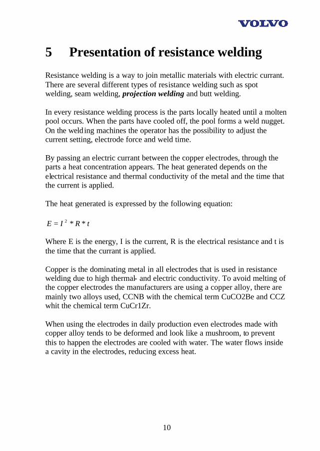
5 Presentation of resistance welding Resistance welding is a way to join metallic materials with electric currant. There are several different types of resistance welding such as spot welding, seam welding, projection welding and butt welding. In every resistance welding process is the parts locally heated until a molten pool occurs. When the parts have cooled off, the pool forms a weld nugget. On the welding machines the operator has the possibility to adjust the current setting, electrode force and weld time. By passing an electric currant between the copper electrodes, through the parts a heat concentration appears. The heat generated depends on the electrical resistance and thermal conductivity of the metal and the time that the current is applied. The heat generated is expressed by the following equation:
tRIE ∗∗= 2 Where E is the energy, I is the current, R is the electrical resistance and t is the time that the currant is applied. Copper is the dominating metal in all electrodes that is used in resistance welding due to high thermal- and electric conductivity. To avoid melting of the copper electrodes the manufacturers are using a copper alloy, there are mainly two alloys used, CCNB with the chemical term CuCO2Be and CCZ whit the chemical term CuCr1Zr. When using the electrodes in daily production even electrodes made with copper alloy tends to be deformed and look like a mushroom, to prevent this to happen the electrodes are cooled with water. The water flows inside a cavity in the electrodes, reducing excess heat.

11
During the welding the electrodes are held under a controlled and predefined force, this force affects then the resistance across the interface between the work pieces and the electrodes. The force and the current creates a heat at the interface between the work pieces, furthermore the force refines the grain structure of the weld (Pic. 3). If the force is to low expulsion, or weld splash, can occur. Different metals need different heat concentrations to produce a molten pool based on electrical conductivity and melting point of the metal. [10]
Pic. 3: Work pieces that are exposed of electrode force and electrical current witch results
in a weld nugget. [3]
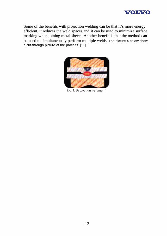
5.1 Projection welding Projection welding is one kind of resistance welding where current flow is focused on the contact surface by an embossed or machined projection. Due to that the projection effectively localizes the current, resistance welding can be used in cases where conventional resistance spot welding won’t work. “Projection welding is a variation of resistance welding that utilizes a projection to concentrate the current flow at the exact point where the joint is desired.” Since the projection usually collapses in a early state of the welding procedure, the local heating make the resistivity within the material rise, it helps further heating and finally it make better weld development at the initial contact point. Due to that the formation on the weld is very localized, this welding method is far more energy efficient than other methods.
12
Some of the benefits with projection welding can be that it’s more energy efficient, it reduces the weld spaces and it can be used to minimize surface marking when joining metal sheets. Another benefit is that the method can be used to simultaneously perform multiple welds. The picture 4 below show a cut-through picture of the process. [11]
Pic. 4: Projection welding [4]
13
6 Presentation of the grounding nuts
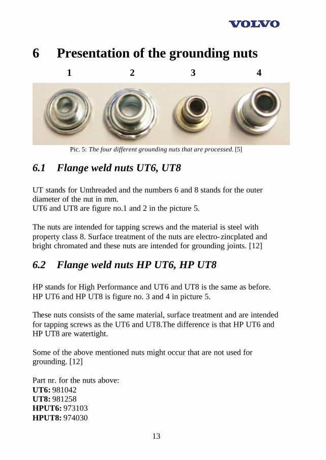
Pic. 5: The four different grounding nuts that are processed. [5]
6.1 Flange weld nuts UT6, UT8 UT stands for Unthreaded and the numbers 6 and 8 stands for the outer diameter of the nut in mm. UT6 and UT8 are figure no.1 and 2 in the picture 5. The nuts are intended for tapping screws and the material is steel with property class 8. Surface treatment of the nuts are electro-zincplated and bright chromated and these nuts are intended for grounding joints. [12]
6.2 Flange weld nuts HP UT6, HP UT8 HP stands for High Performance and UT6 and UT8 is the same as before. HP UT6 and HP UT8 is figure no. 3 and 4 in picture 5. These nuts consists of the same material, surface treatment and are intended for tapping screws as the UT6 and UT8.The difference is that HP UT6 and HP UT8 are watertight. Some of the above mentioned nuts might occur that are not used for grounding. [12] Part nr. for the nuts above: UT6: 981042 UT8: 981258 HPUT6: 973103 HPUT8: 974030
1 2 3 4
14
7 Presentation of the materials
7.1 Steel V-1158 This is a zinc-coated cold-rolled sheet metal, it is used mainly for deep drawing. One of its big benefits is that it has non-ageing quality. It is a low-strength steel with coating in the form of hot dip zinc coating, zinc- iron coating or electro-zincplating. The weldability of this steel is good. [12]
7.2 Steel V-1343 This is a high strength steel mainly for deep drawing. The tensile strength min. is 340 N/mm2 . Steel V-1343 is usually of the so called Rephos type, in the form of cold-rolled sheets. Rephos steels (Rephosphorized) have raised phosphorus content. The steel is easily welded using resistance-welding techniques such as spot and seam welding. Fusion welding is also possible. [12]
7.3 Steel V-1357 This steel has the exact same properties as V-1343, except for that the sheets of this material are zinc-coated. [12]
7.4 Steel V-1423 This is a high strength steel mainly for deep drawing. The tensile strength min. is 380 N/mm2 . Steel V-1423 is usually of the so called Rephos type, in the form of cold-rolled sheets. The steel is easily welded using resistance-welding techniques such as spot and seam welding. Fusion welding is also possible. [12]
7.5 Steel V-1568 This is an ultrahigh-strength steel with a tensile strength min. 1400 N/mm2. Steel V-1568 is boron-alloyed, intended for hardening. The delivery forms are hot- and cold-rolled steel sheets. [12]

15
7.6 Steel V-1148 This is a cold-rolled sheet metal, it is used mainly for deep drawing. One of its big benefits is that it has non-ageing quality. The steel is suitable for normal welding procedures. Resistance welding, e.g. spot (and seam) welding, can be performed without difficulty. [12]
7.7 Steel V-1157 This steel has almost identical properties with the V-1158 steel. [12]
7.8 Steel V-1437 This is a zinc-coated high-strength steel mainly for deep drawing. The tensile strength min. is 380 N/mm2. Steel V-1437 is usually of the so called Rephos type, in the form of zinc-coated and cold-rolled sheets. The steel is easily welded using resistance-welding techniques such as spot and seam welding. Fusion welding is also possible. [12]
7.9 Steel V-1478 This is a zinc-coated extra high-strength steel mainly for deep drawing. The tensile strength min. is 600 N/mm2. Steel V-1478 is a high-strength steel of the so-called DP type. It is in the form of zinc-coated hot- or cold-rolled sheets. DP (Dual Phase) has a microstructure cons isting of ferrite and martensite. The steel is easily welded using resistance-welding techniques such as spot and seam welding. Fusion welding is also possible. [12]
7.10 Welding in zinc-coated materials Zinc-coated materials can be resistance welded (spot, seam and projection welding) with a satisfactory result. Compared to welding of uncoated material, more powerful welding equipment and a clearly increased maintenance together with increased supervision and more extensive are, however, required. At fusion welding, the difficulties caused by the surface coating are aggravated with increasing coating mass. Due to its low heat supply, gas arc welding (short arc welding) is the most suitable method.
16
At all types of welding, particularly at fusion welding of the coated sheet, the zinc vaporizes. Due to the risk of the personnel being exposed to zinc, direct evacuation of the weld smoke must be arranged. [12]
7.11 Coating All coatings are represented with an extension to the standard denomination, and they are: Z – hot dip zinc coating ZE – electro-zinc plating ZF – zinc- iron alloy coating 100 – 275 is the mass of the coating, measured by triple-spot test [g/m2] A, B and C represents the surface quality. [12]
17
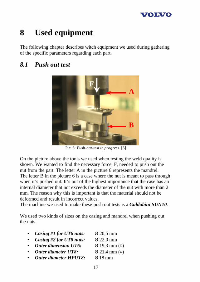
8 Used equipment The following chapter describes witch equipment we used during gathering of the specific parameters regarding each part.
8.1 Push out test
Pic. 6: Push-out-test in progress. [5]
On the picture above the tools we used when testing the weld quality is shown. We wanted to find the necessary force, F, needed to push out the nut from the part. The letter A in the picture 6 represents the mandrel. The letter B in the picture 6 is a case where the nut is meant to pass through when it’s pushed out. It’s out of the highest importance that the case has an internal diameter that not exceeds the diameter of the nut with more than 2 mm. The reason why this is important is that the material should not be deformed and result in incorrect values. The machine we used to make these push-out tests is a Galdabini SUN10. We used two kinds of sizes on the casing and mandrel when pushing out the nuts.
• Casing #1 for UT6 nuts: Ø 20,5 mm • Casing #2 for UT8 nuts: Ø 22,0 mm • Outer dimension UT6: Ø 19,3 mm (¤) • Outer diameter UT8: Ø 21,4 mm (¤) • Outer diameter HPUT8: Ø 18 mm
A
B
F
18
(¤): Due to the 12 edges on the UT nut, the dimension is measured by hand as a complement to the VCBC standard. This is made to ensure that the Casing/Mandrel relation is correct. (See geometry of the nut in figure 1 and 2 in picture 5.)
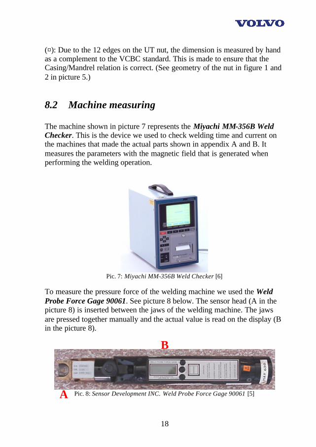
8.2 Machine measuring The machine shown in picture 7 represents the Miyachi MM-356B Weld Checker. This is the device we used to check welding time and current on the machines that made the actual parts shown in appendix A and B. It measures the parameters with the magnetic field that is generated when performing the welding operation.
Pic. 7: Miyachi MM-356B Weld Checker [6]
To measure the pressure force of the welding machine we used the Weld Probe Force Gage 90061. See picture 8 below. The sensor head (A in the picture 8) is inserted between the jaws of the welding machine. The jaws are pressed together manually and the actual value is read on the display (B in the picture 8).
Pic. 8: Sensor Development INC. Weld Probe Force Gage 90061 [5] A
B
19
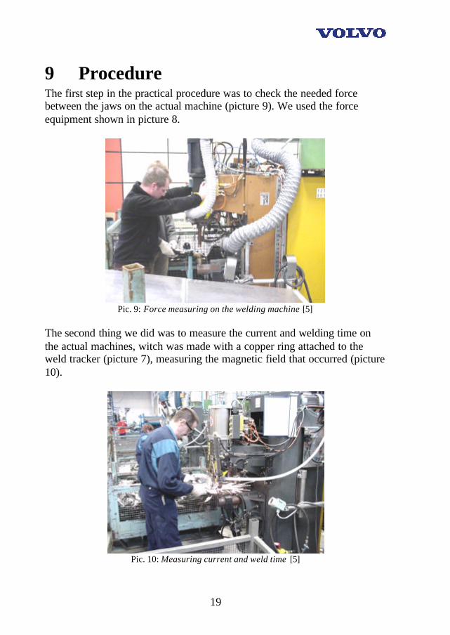
9 Procedure The first step in the practical procedure was to check the needed force between the jaws on the actual machine (picture 9). We used the force equipment shown in picture 8.
Pic. 9: Force measuring on the welding machine [5]
The second thing we did was to measure the current and welding time on the actual machines, witch was made with a copper ring attached to the weld tracker (picture 7), measuring the magnetic field that occurred (picture 10).
Pic. 10: Measuring current and weld time [5]
20
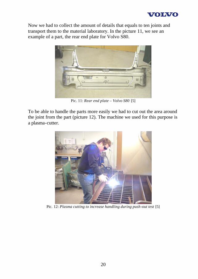
Now we had to collect the amount of details that equals to ten joints and transport them to the material laboratory. In the picture 11, we see an example of a part, the rear end plate for Volvo S80.
Pic. 11: Rear end plate – Volvo S80 [5]
To be able to handle the parts more easily we had to cut out the area around the joint from the part (picture 12). The machine we used for this purpose is a plasma-cutter.
Pic. 12: Plasma cutting to increase handling during push-out test [5]

21
After cutting out the joints from the actual parts we labeled them and put them together into convenient bunches that were easy to organize and handle when making the push-out tests. The result is shown in the picture 13.
Pic. 13: Labeled and sorted before testing [5]
The machine we used when making the push-out test (e.g. inverted tensile test) is a Galdabini SUN 10 tensile testing machine that are shown below in picture 14. This machine is already mentioned earlier in this report under the header "Used equipment".
Pic. 14: Tensile test machine used for the push-out test [5]
22
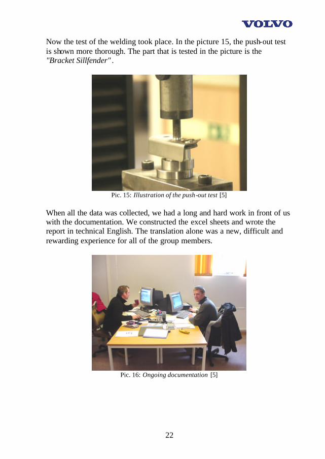
Now the test of the welding took place. In the picture 15, the push-out test is shown more thorough. The part that is tested in the picture is the "Bracket Sillfender" .
Pic. 15: Illustration of the push-out test [5]
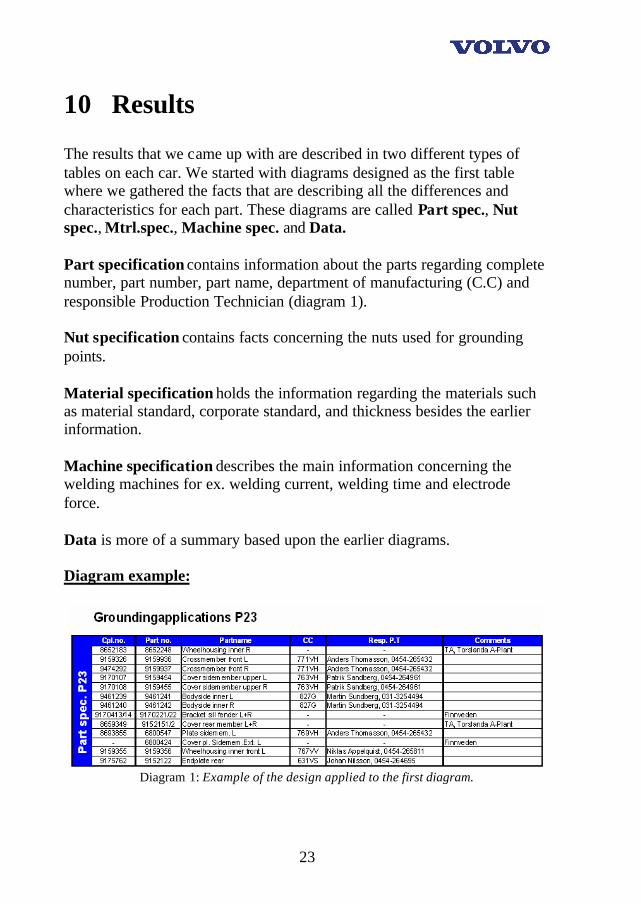
When all the data was collected, we had a long and hard work in front of us with the documentation. We constructed the excel sheets and wrote the report in technical English. The translation alone was a new, difficult and rewarding experience for all of the group members.
Pic. 16: Ongoing documentation [5]
23
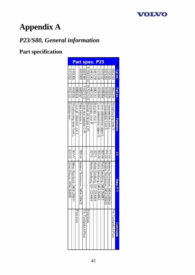
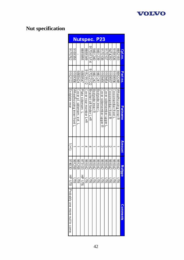
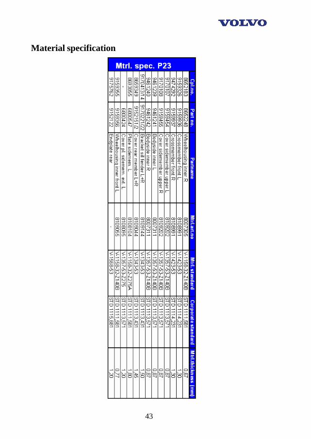
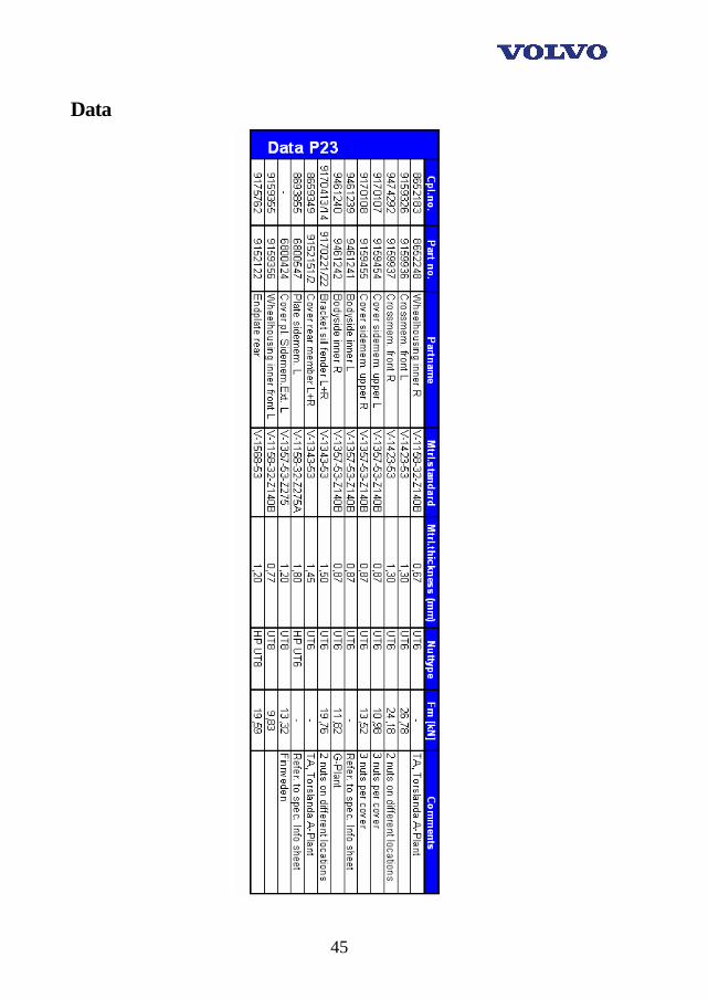
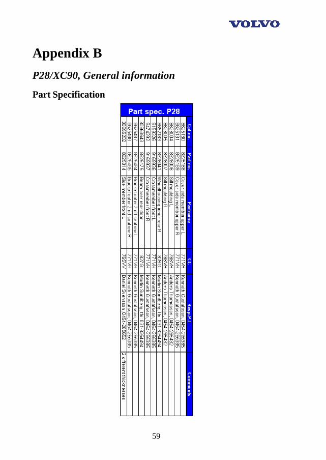
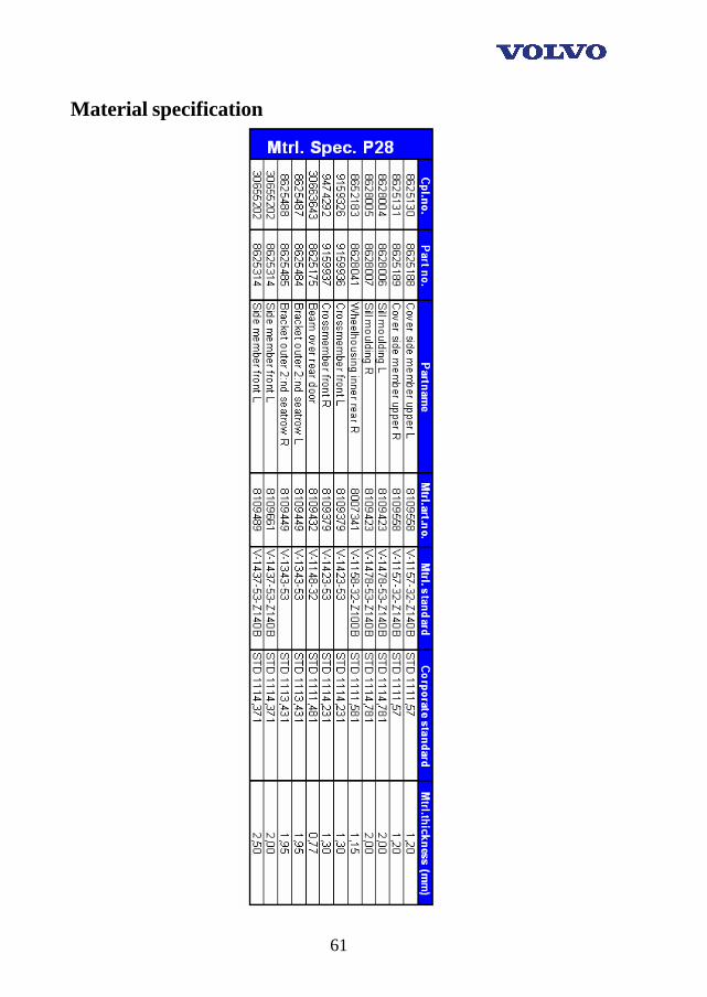
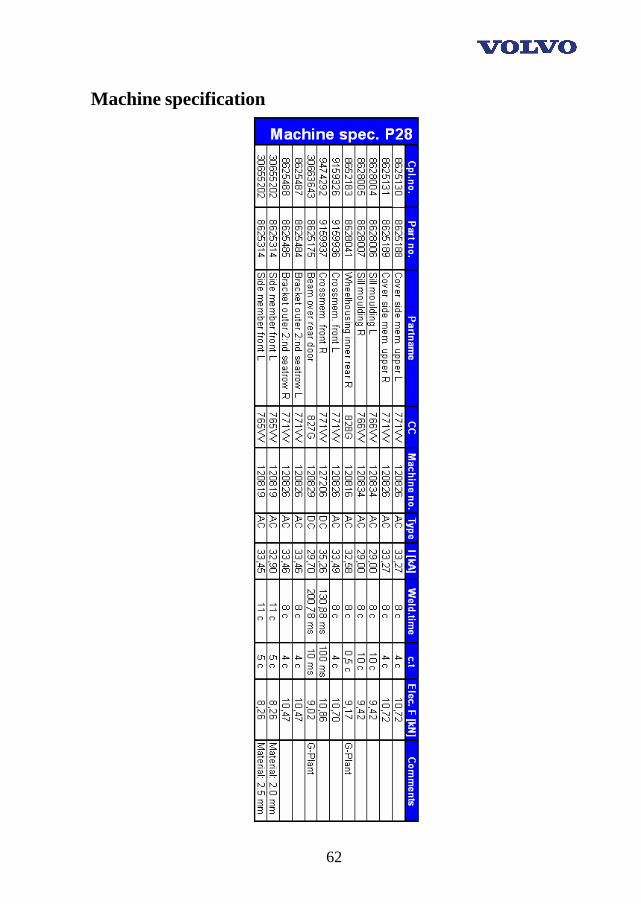
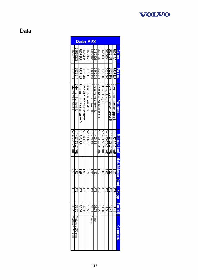
10 Results The results that we came up with are described in two different types of tables on each car. We started with diagrams designed as the first table where we gathered the facts that are describing all the differences and characteristics for each part. These diagrams are called Part spec., Nut spec., Mtrl.spec., Machine spec. and Data. Part specification contains information about the parts regarding complete number, part number, part name, department of manufacturing (C.C) and responsible Production Technician (diagram 1). Nut specification contains facts concerning the nuts used for grounding points. Material specification holds the information regarding the materials such as material standard, corporate standard, and thickness besides the earlier information. Machine specification describes the main information concerning the welding machines for ex. welding current, welding time and electrode force. Data is more of a summary based upon the earlier diagrams. Diagram example:
Diagram 1: Example of the design applied to the first diagram.
24
These nuts are placed on different locations of the body. The different locations are shown in the appendixes in the end of this report. The second type of diagrams contains information concerning welding quality, type of failure and which applications that are grounded in respective grounding joint (diagram 2). Regarding the Volvo Inspection Report there was not any facts provided to us from the production personal to make an analysis, therefore this subsection was ruled out. To the question about the basic requirements for the dimensioning and choice of grounding applications for the electrical subsystems on the cars of today and tomorrow, we felt that we didn't have enough knowledge to make such suggestions and advisement. It was already from the start highly uncertain that we should be able to complete this subsection due to time limit set for this thesis. Diagram example:
Diagram 2: Example of the design applied to the second diagram.
25
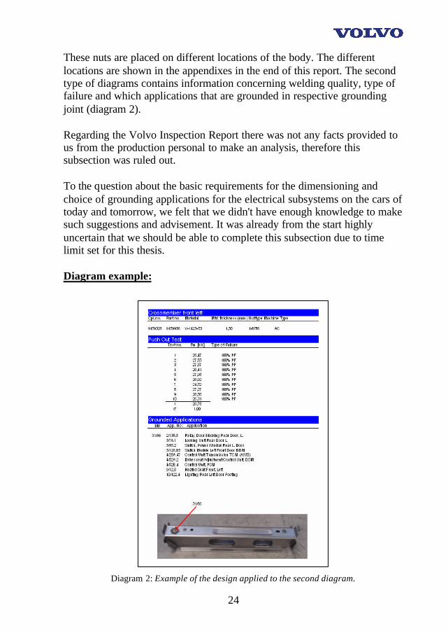
11 Discussion of the results This chapter is about witch parts we thought needed closer attention and some proposals of what to do, but first the types of failure that we encountered.
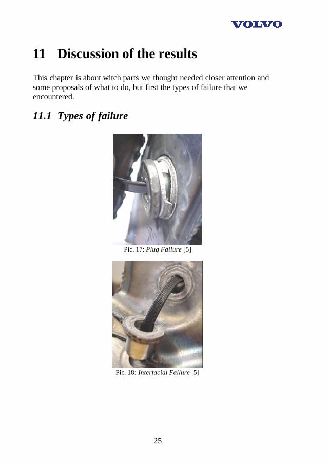
11.1 Types of failure
Pic. 17: Plug Failure [5]
Pic. 18: Interfacial Failure [5]
26
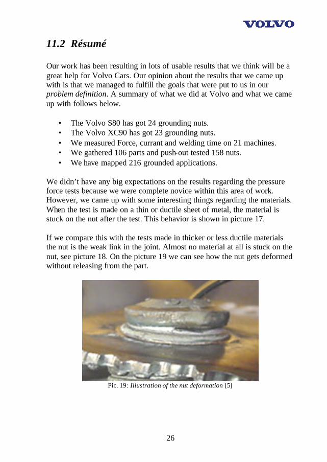
11.2 Résumé Our work has been resulting in lots of usable results that we think will be a great help for Volvo Cars. Our opinion about the results that we came up with is that we managed to fulfill the goals that were put to us in our problem definition. A summary of what we did at Volvo and what we came up with follows below.
• The Volvo S80 has got 24 grounding nuts. • The Volvo XC90 has got 23 grounding nuts. • We measured Force, currant and welding time on 21 machines. • We gathered 106 parts and push-out tested 158 nuts. • We have mapped 216 grounded applications.
We didn’t have any big expectations on the results regarding the pressure force tests because we were complete novice within this area of work. However, we came up with some interesting things regarding the materials. When the test is made on a thin or ductile sheet of metal, the material is stuck on the nut after the test. This behavior is shown in picture 17. If we compare this with the tests made in thicker or less ductile materials the nut is the weak link in the joint. Almost no material at all is stuck on the nut, see picture 18. On the picture 19 we can see how the nut gets deformed without releasing from the part.
Pic. 19: Illustration of the nut deformation [5]
27
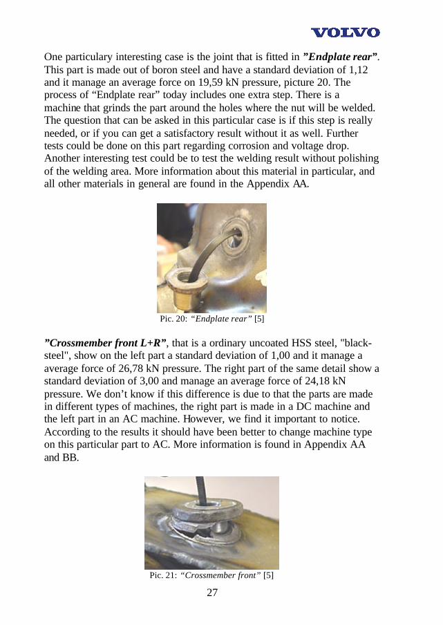
One particulary interesting case is the joint that is fitted in ”Endplate rear”. This part is made out of boron steel and have a standard deviation of 1,12 and it manage an average force on 19,59 kN pressure, picture 20. The process of “Endplate rear” today includes one extra step. There is a machine that grinds the part around the holes where the nut will be welded. The question that can be asked in this particular case is if this step is really needed, or if you can get a satisfactory result without it as well. Further tests could be done on this part regarding corrosion and voltage drop. Another interesting test could be to test the welding result without polishing of the welding area. More information about this material in particular, and all other materials in general are found in the Appendix AA.
Pic. 20: “Endplate rear” [5]
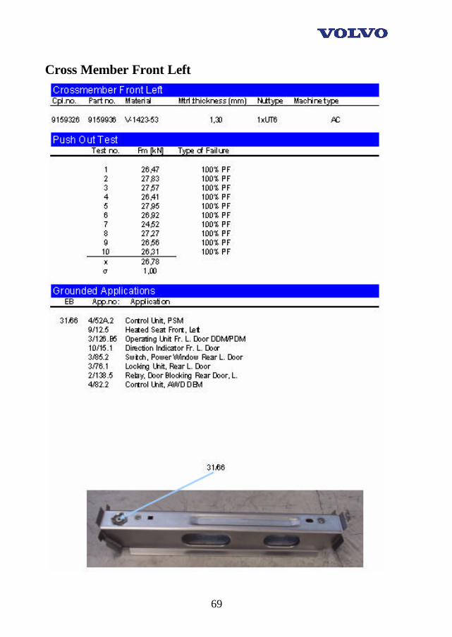
”Crossmember front L+R”, that is a ordinary uncoated HSS steel, "black-steel", show on the left part a standard deviation of 1,00 and it manage a average force of 26,78 kN pressure. The right part of the same detail show a standard deviation of 3,00 and manage an average force of 24,18 kN pressure. We don’t know if this difference is due to that the parts are made in different types of machines, the right part is made in a DC machine and the left part in an AC machine. However, we find it important to notice. According to the results it should have been better to change machine type on this particular part to AC. More information is found in Appendix AA and BB.
Pic. 21: “Crossmember front” [5]

28
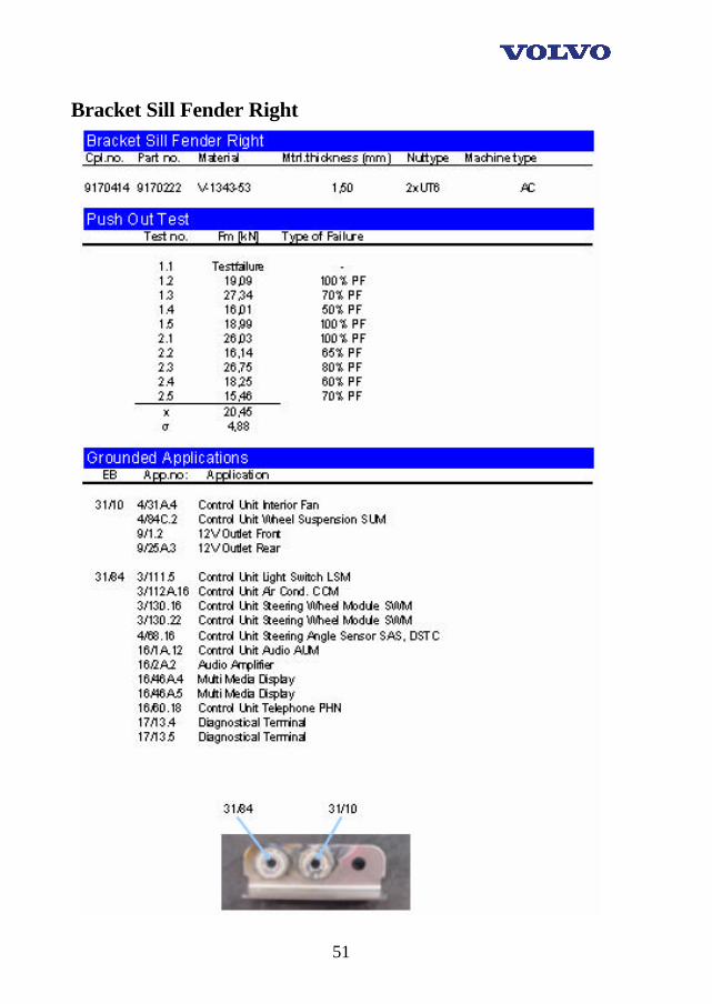
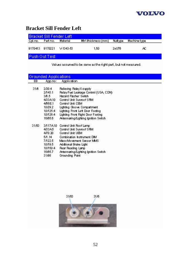
”Bracket sillfender” is made on Finnveden, subcontractor to VCBC, and this part have a standard deviation of 4,88 and it manage an average force of 20,45 kN, pressure. The results regarding this particular part show that the standard deviation is big and that the PF (Plug Failure) exceeds the approved limit. Our strong advise is that this part is more thorough investigated due to that there are many important devices grounded in this part, for example CEM and UEM. It is out of the highest importance that the welding in this part is ensured to be out of good quality. More information about this part is found in Appendix AA.
Pic. 22: “Bracket sillfender” [5]
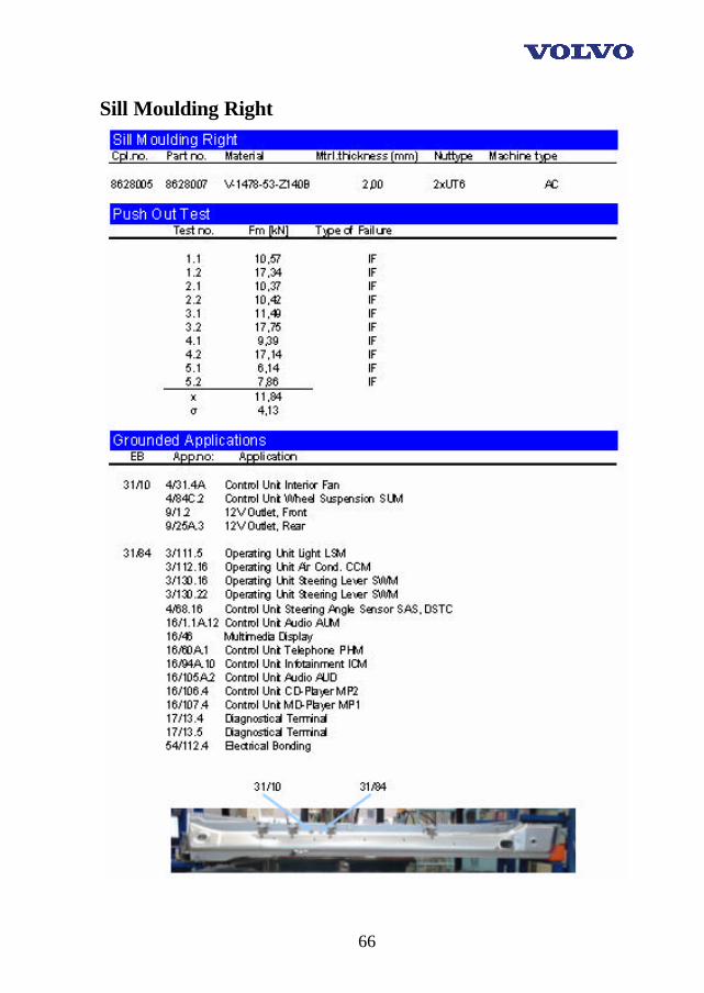
”Sill Moulding” is manufactured in a material called V-1478-53-Z140B. This steel is sometimes called DP600 and it has a coating of 10 µm zinc (nom.). The test results showed that it has a standard deviation of 4,13 and it manage an average force of 11,78 kN, pressure, picture 23. The process that this part is welded in should need an improvement considering the standard deviation. Of course there can be natural causes to the welding results. The material is rather thick and it’s coated with zinc. However, our advise is to investigate this more thorough. More information is found in Appendix BB.
Pic. 23: “Sill Moulding” [5]
29
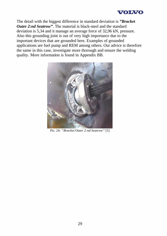
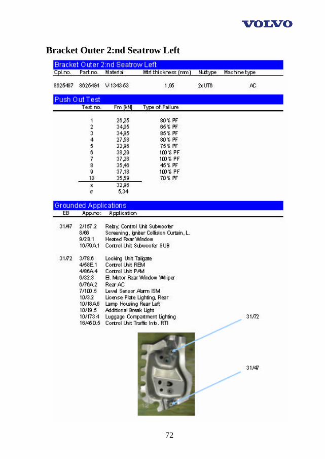
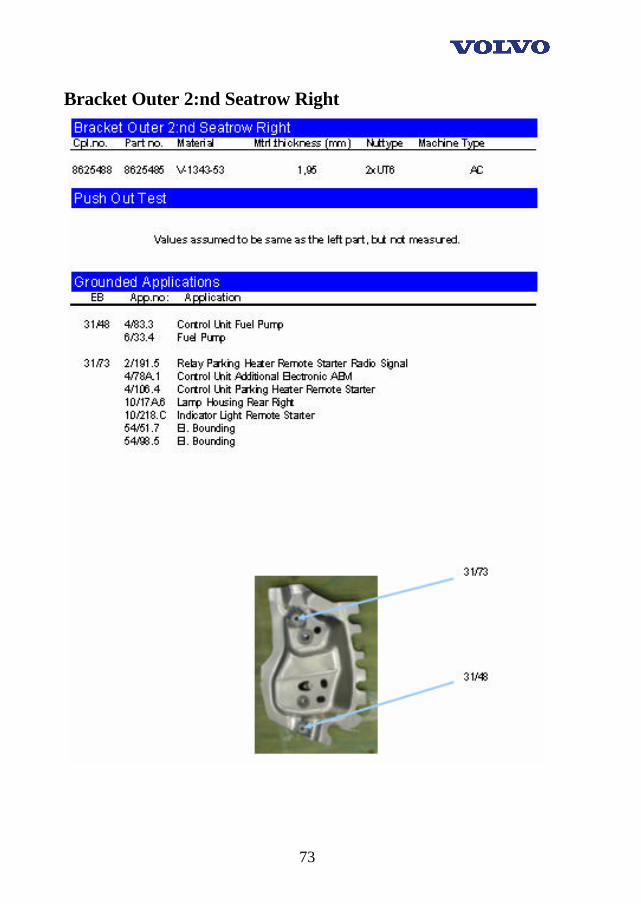
The detail with the biggest difference in standard deviation is ”Bracket Outer 2:nd Seatrow”. The material is black-steel and the standard deviation is 5,34 and it manage an average force of 32,96 kN, pressure. Also this grounding joint is out of very high importance due to the important devices that are grounded here. Examples of grounded applications are fuel pump and REM among others. Our advice is therefore the same in this case, investigate more thorough and ensure the welding quality. More information is found in Appendix BB.
Pic. 24: “Bracket Outer 2:nd Seatrow” [5]
30
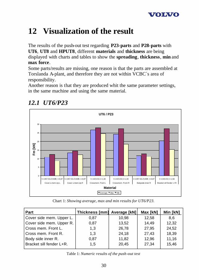
12 Visualization of the result The results of the push-out test regarding P23-parts and P28-parts with UT6, UT8 and HPUT8, different materials and thickness are being displayed with charts and tables to show the spreading, thickness, min and max force. Some parts/results are missing, one reason is that the parts are assembled at Torslanda A-plant, and therefore they are not within VCBC´s area of responsibility. Another reason is that they are produced whit the same parameter settings, in the same machine and using the same material.
12.1 UT6/P23
UT6 / P23
0
5
10
15
20
25
30
V-1357-53-Z140B; t=0,87 V-1357-53-Z140B; t=0,87 V-1423-53; t=1,30 V-1423-53; t=1,30 V-1357-53-Z140B; t=0,87 V-1343-53; t=1,50
Cover s.mem.Up.L Cover s.mem.Up.R Crossmem. Front L Crossmem. Front R Bodyside inner R Bracket sill fender L+R
Material
Fm
[kN
]
Average Max Min
Chart 1: Showing average, max and min results for UT6/P23.
Part Thickness [mm] Average [kN] Max [kN] Min [kN] Cover side mem. Upper L. 0,87 10,98 12,58 8,6 Cover side mem. Upper R. 0,87 13,52 14,49 12,32 Cross mem. Front L. 1,3 26,78 27,95 24,52 Cross mem. Front R. 1,3 24,18 27,43 18,39 Body side inner R. 0,87 11,82 12,96 11,16 Bracket sill fender L+R. 1,5 20,45 27,34 15,46
Table 1: Numeric results of the push-out test

31
12.2 UT8/P23
UT8 / P23
05
101520
V-1357-53-Z275; t=1,20 V-1158-32-Z140B; t=0,77
Cover pl.side mem.ext.L Wheelhousing inner fr.L
Material
Fm
[kN
]
Average Max Min
Chart 2: Showing average, max and min results for UT8/P23.
Part Thickness [mm] Average [kN] Max [kN] Min [kN] Cover plate side mem. Ext. L. 1,20 13,32 16,75 8,28 Wheel housing inner front L. 0,77 9,83 10,30 8,97
Table 2: Numeric results of the push-out test.
12.3 HPUT8/P23
HPUT8/P23
0
10
20
V-1568-53; t=1,20 Endplate rear Material
Fm
[kN
]
Average Max Min
Chart 3: Showing average, max and min results for HPUT8/P23.
Part Thickness [mm] Average [kN] Max [kN] Min [kN] Endplate rear 1,20 19,59 21,42 18,03
Table 3: Numeric results of the push-out test.

32
12.4 UT6/P28
UT6/P28
0102030
V-1157-32-Z140B;t=1,20
V-1478-53-Z140B;t=2,00
V-1158-32-Z100B;t=1,15
V-1423-53; t=1,30
Cover s.mem.Up.R. Sill moulding R. Wheelhousingin.r.R.
Crossmem. Front L
Material
Fm
[kN
]
Average Max Min
Chart 4: Showing average, max and min results for UT6/P28.
Part Thickness [mm] Average [kN] Max [kN] Min [kN] Cover side mem. Upper R. 1,20 16,4 17,1 15,99 Sill moulding R. 2,00 11,48 17,75 6,14 Wheel housing inner rear R. 1,15 13,93 14,63 13,08 Cross mem. Front L 1,30 26,78 27,83 24,52
Table 4: Numeric results of the push-out test.
UT6/P28
01020304050
V-1423-53; t=1,30 V-1148-32; t=0,77 V-1343-53; t=1,95
Crossmem. Front R Beam over r.door Bracket outer 2:nd s.r.L.
Material
Fm
[kN
]
Average Max Min
Chart 5: Showing average, max and min results for UT6/P28.
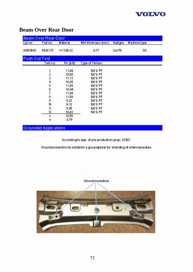
Part Thickness [mm] Average [kN] Max [kN] Min [kN] Cross mem. Front R 1,30 24,18 27,43 18,39 Beam over rear door 0,77 10,5 11,58 9,12 Bracket outer 2:nd seat row L. 1,95 32,96 38,29 22,96
Table 5: Numeric results of the push-out test.
33
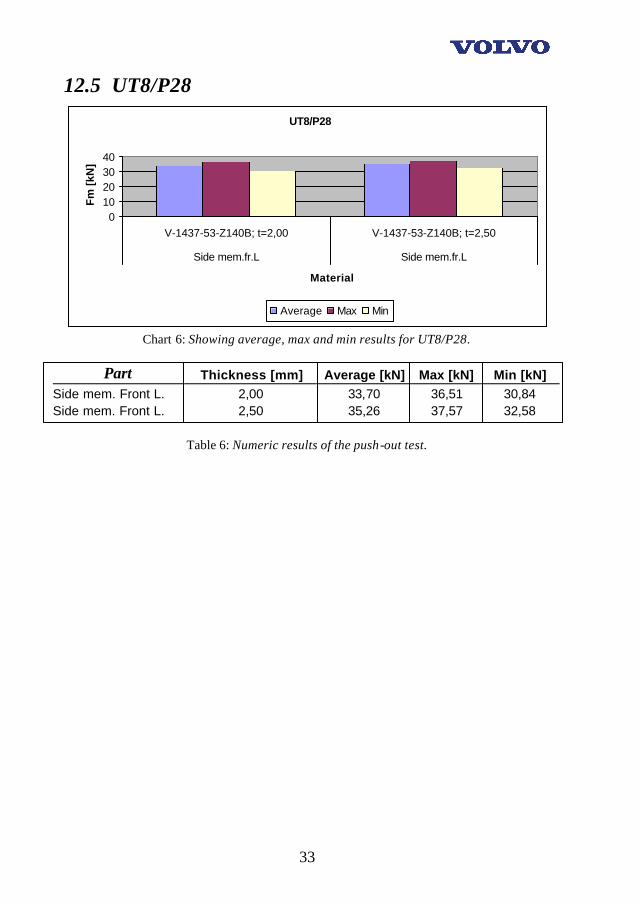
12.5 UT8/P28
UT8/P28
010203040
V-1437-53-Z140B; t=2,00 V-1437-53-Z140B; t=2,50
Side mem.fr.L Side mem.fr.L
Material
Fm
[kN
]
Average Max Min
Chart 6: Showing average, max and min results for UT8/P28.
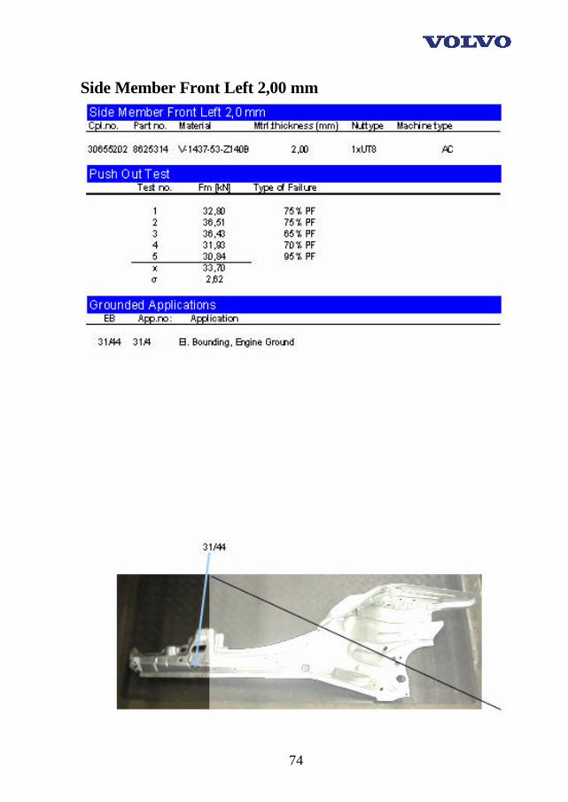
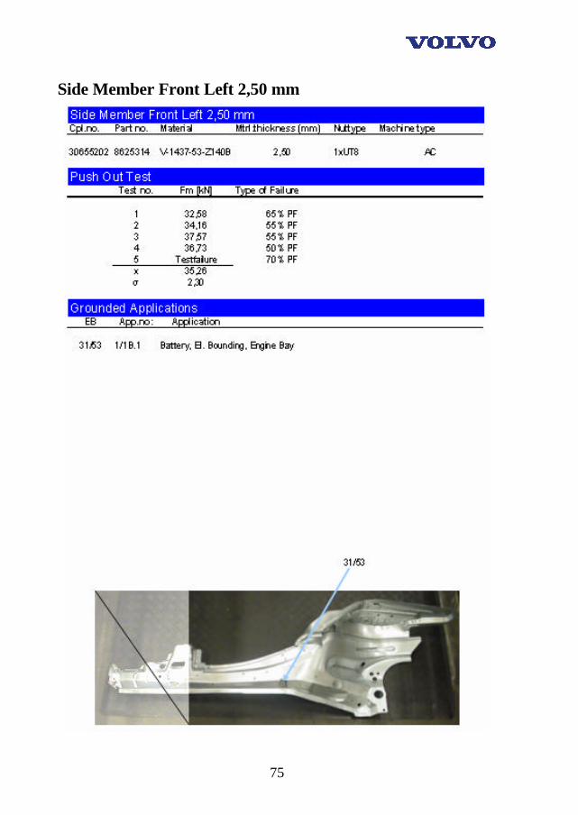
Part Thickness [mm] Average [kN] Max [kN] Min [kN] Side mem. Front L. 2,00 33,70 36,51 30,84 Side mem. Front L. 2,50 35,26 37,57 32,58
Table 6: Numeric results of the push-out test.
34
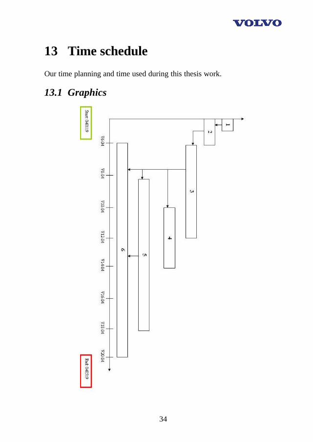
13 Time schedule Our time planning and time used during this thesis work.
13.1 Graphics
35
13.2 Explanations 1: Start This is where the project is getting started. We receive a working area where we can sit, a computer is given to us and we get the necessary information and material. 2: Defining the problem The problems are being collected and sorted, the demands/wishes of the project are gathered through conversation with the instructors from VCBC, Olofström. 3: Getting the facts A large amount of facts is being collected out of documents, already made tests and the employees of the company. 4: Physical laboratory experiments The meaning with this step is that physical tests are going to take place. Examples of these can be tensile tests. 5: Solving the problem The problems are specified and they are solved according to the company's desire. Conclusions are made and facts are put together. 6: Documentation, translation At this point the report is being made and the script is analyzed and translated into the concern language, English. This is made so that even abroad employees can reach the information.
36
14 Conclusions This examination thesis has been very interesting, amusing and we learned a lot about the subject. We also became even closer to each other as a group. The work has been going without any bigger obstacles in our way. There were a few moments when we thought that we shouldn’t be done with our work on time. However, we managed to solve our main tasks within our timeframe and we ourselves are very happy with the outcome. We hope and suspect that this project has given VCBC what they asked for and that they are as happy with the results as we are. Our project has included lots of information research and it has been very social and we received some good contacts within the entire concern Volvo Cars. Of course our results can be refined and refilled by information and additional matters that we didn’t deal with in this project. One of the things that we remember as the brightest was the meeting in Göteborg with Mr. Mats Swala. The welcoming and the information we received by him were of top class. It’s always a pleasure to work with good people. The general opinion of the personnel on Volvo, Göteborg, seems to be that projects of this kind are very good to unite the entire company. Gluing the personnel and work tasks tighter together makes this become reality. Another person that we would like to send exclusive thanks to is Mrs. Lea Bengtsson that has been our supervisor on VCBC. She has been very supportive and helped us much with our practical work such as measuring of the machines. There is even one more notice to make within this conclusion. We have been very good taken care of by all the people that we have been working with, and for. Questions have been answered, explanations have been given and doors have been opened. Finally we hope that You as a reader of this report got a much better understanding of how important grounding really is. We also hope that You thought the report and its content was as interesting as we did. And again, thank You all! The authors Karlskrona, 06-May-2004

37
15 Thanks We want to thank all of you who helped us during our journey!! School of Engineering/Department of Mechanical Engineering – BTH. We also want to give a special thanks to. Olofström: Anders Boking, Manager Process Development. Lea Bengtsson, M. Sc, our supervisor Linn Björgvik, Mechanical Engineer, our mainstay Jerzy Szadurski, Laboratory Engineer Paula Sander, Process Engineer, for the run through of KDP and PROBAS Muammer Lapovski, Laboratory Engineer Christer Kullman, P.T, which helped us during the measurement on the machines. Kenth Johnsson, Measurement Engineer, helping us with the drawings regarding P23 and P28 Siv Möller, the Archive Anneli Vanamo, the Archive Göteborg: Mats Swala, EDS, for vital information and invaluable guidance. Special thanks for the very nice welcoming and the amusing visit. Örjan Spjuth, EDS, for providing the PDF files regarding grounded applications. Mats Roos , EDS, for the help with the virtual files of the wiring diagram P28. Mats Bäckerstam, P.T, for helping us during gathering of welding parameters. Martin Sundberg, Project Manager, for his time during our visit.

38
16 References
16.1 Pictures [1]: http://www.volvocars.ford.com/specialvehicles/product/S80Executive.ppt [2]: http://www.volvocars.ford.com/specialvehicles/vcspresentation.ppt [3]: http://www.caclase.se/ind/motstand/motstand.htm [4]: http://www.medar.com/welding_concepts/projectionweld.html [5]: Digital picture made by VCBC. [6]: http://www.miyachi1.com/Products_Item_View.asp?ID=18
16.2 Written text
[7]: VCC Intranet, Corporate presentation 2004, http://www.volvocars.ford.com/corpmtrl/ppt/corporatepresentation_VCC2004.ppt [8]: VCBC [9]: www.volvoXC90.se [10]: www.weldtechnology.com/rwintroduction.html [11]: http://www.ewi.org/technologies/resistance/resistance.asp#proj [12]: VCC intranet, Corporate Standard
The following sources have been used all through the project.
• School of Engineering, Department of Mechanical Engineering, BTH (Blekinge Institute of Technology)
• Volvo wiring diagram TP 3971012 and TP 3970012 • VCBC database PROBAS • VCC database KDP
Consideration is taken to valid secrecy agreement .

39
Appendix

40
41
Appendix A
P23/S80, General information
Part specification
42
Nut specification
43
Material specification

44
Machine specification
45
Data

46
Appendix AA
P23/S80, Specific information
Cross member Front Left

47
Cross member Front Right
48
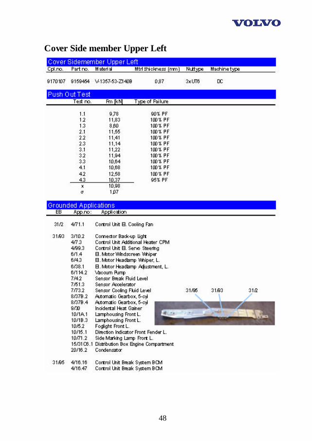
Cover Side member Upper Left
49
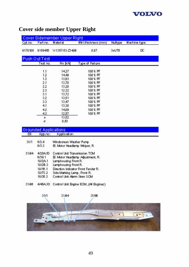
Cover side member Upper Right
50
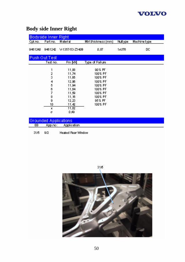
Body side Inner Right
51
Bracket Sill Fender Right
52
Bracket Sill Fender Left
53
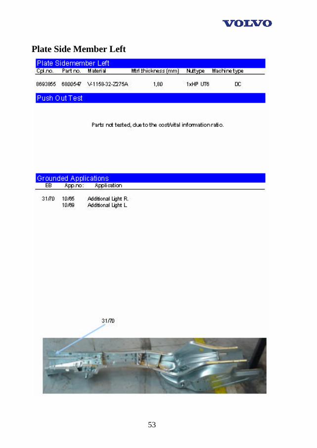
Plate Side Member Left
54
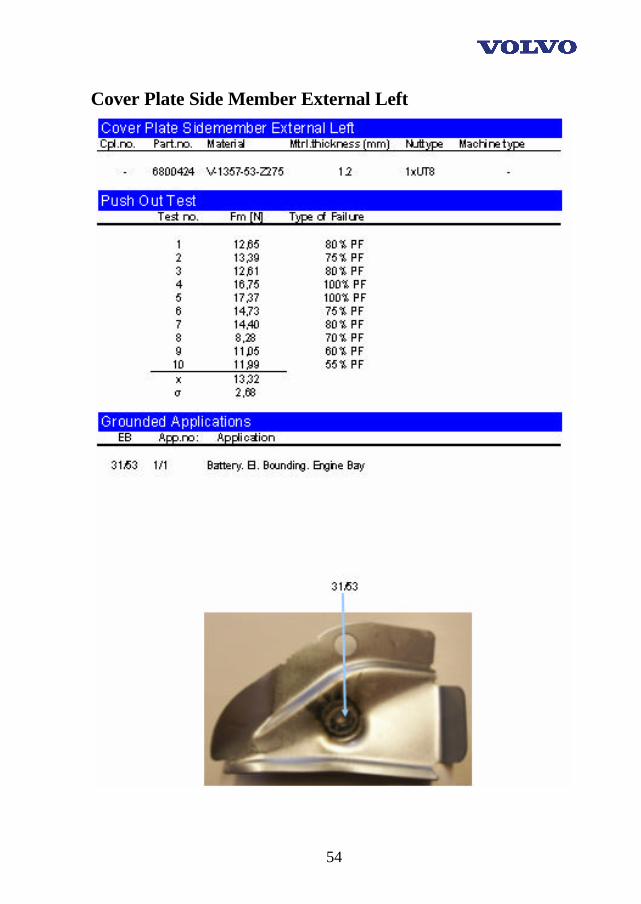
Cover Plate Side Member External Left
55
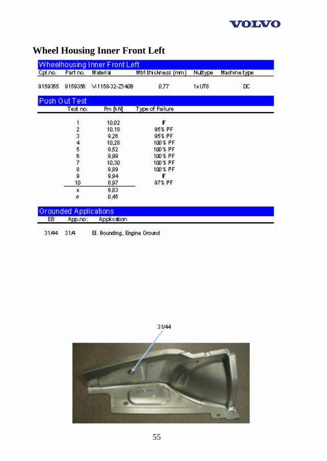
Wheel Housing Inner Front Left
56
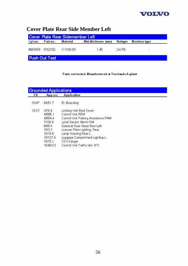
Cover Plate Rear Side Member Left
57
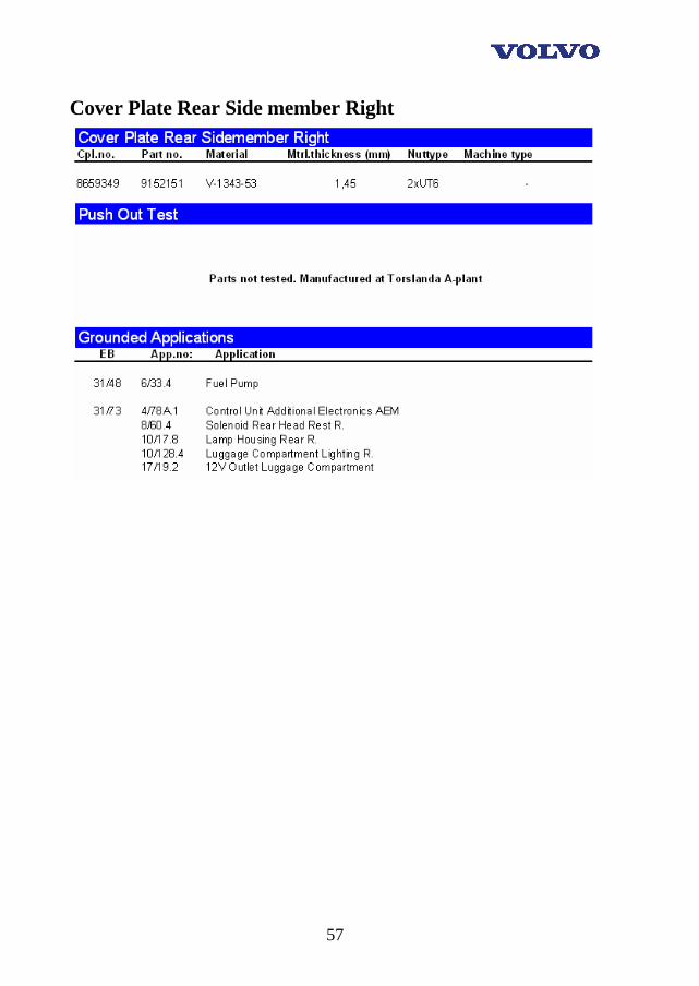
Cover Plate Rear Side member Right

58
Endplate Rear
59
Appendix B
P28/XC90, General information
Part Specification

60
Nut specification
61
Material specification
62
Machine specification
63
Data
64
Appendix BB
P28/XC90, Specific information
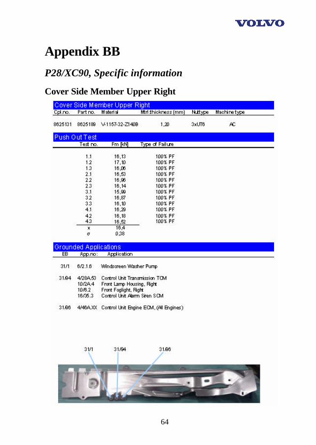
Cover Side Member Upper Right
65
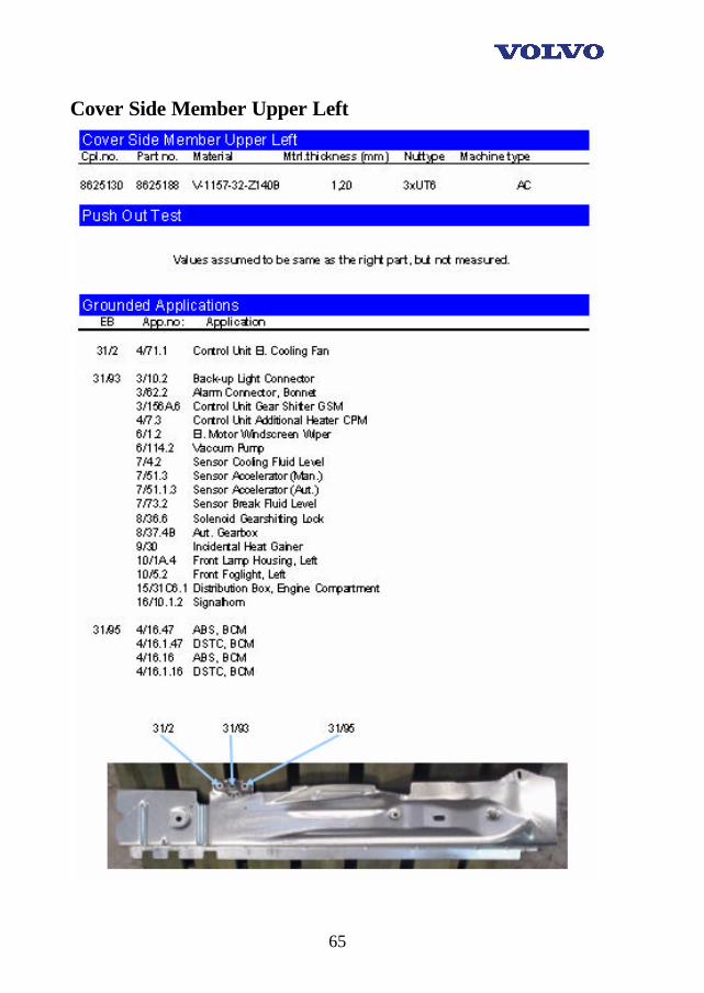
Cover Side Member Upper Left
66
Sill Moulding Right
67
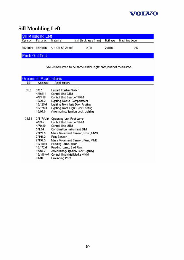
Sill Moulding Left
68
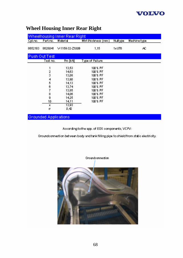
Wheel Housing Inner Rear Right
69
Cross Member Front Left

70
Cross Member Front Right
71
Beam Over Rear Door
72
Bracket Outer 2:nd Seatrow Left
73
Bracket Outer 2:nd Seatrow Right
74
Side Member Front Left 2,00 mm
75
Side Member Front Left 2,50 mm

76
Contact the authors
Tommy Mikalsen • 23 year old male. Born and raised in Olofström, Blekinge.
• 3 years on senior High School in Olofström, The Industry Programme.
• 2 years on BTH, "Production and Maintenance technician" (80P = 2 years). Resulted in University Technician degree.
• 3 years on BTH, "Product Development Engineer" (120P = 3 years). Resulted in Bachelor of Science degree.
• Mainly no working experience except for 6 summers at VCBC in Olofström where I worked on different places in the production. (Approximately 48 weeks in total).
Address: Hjälmvägen 10 ZIP-code: 29335 City: Olofström Country: Sweden E-mail: [email protected] Phone: +46 454 - 42641 Cellular: +46 73 – 641 40 59 or +46 73 - 80 40 322
77
Jörgen Ahnstedt • 34 year old male.
• 2 years on senior High School in Värnamo, El./Tele.- Steer and Regulate
• 2 years on senior High School in Värnamo, Technical Engineering
• 2 years on BTH, "Production and Maintenance technician" (80P = 2 years).
• 3 years on BTH, "Product Development Engineer" (120P = 3 years). Resulted in Bachelor of Science degree.
• 10 years working experience, mainly industrial. Address: Valhallavägen 4C ZIP-code: 371 40 City: Karlskrona Country: Sweden E-mail: [email protected] Phone: +46 455 - 28048 Cellular: +46 708 - 351606
78
Andreas Agardh • 27 year old male. Born and raised in Brunnby, north of Helsingborg.
• 3 years on senior High School on Tycho Brahe in Helsingborg, The Energy Programme.
• 2 years on BTH, "Production and Maintenance technician" (80P = 2 years). Resulted in University Technician degree.
• 3 years on BTH, "Product Development Engineer" (120P = 3 years). Resulted in Bachelor of Science degree.
• Working experience: 2 years at see as an able seaman and about 8 summers at "Värmeteknik AB" in Höganäs.
Address: Lilla vägen 4 ZIP-code: 260 41 City: Nyhamnsläge Country: Sweden E-mail: [email protected] Phone: +46 42 - 34 66 40 Cellular: +46 708 - 57 97 74