mapping conceptual models to database schemas - byu data
TRANSCRIPT

Chapter 4
Mapping Conceptual Models toDatabase Schemas
David W. Embley and Wai Yin Mok
4.1 Introduction
The mapping of a conceptual-model instance to a database schema is fun-damentally the same for all conceptual models. A conceptual-model instancedescribes the relationships and constraints among the various data items.Given the relationships and constraints, the mappings group data items to-gether into flat relational schemas for relational databases and into nestedrelational schemas for object-based and XML storage structures.
Although we are particularly interested in the basic principles behind themappings, we take the approach of first presenting them in Sections 4.2 and4.3 in terms of mapping an ER model to a relational database. In thesesections, for the ER constructs involved, we (1) provide examples of theconstructs and say what they mean, (2) give rules for mapping the constructsto a relational schema and illustrate the rules with examples, and (3) state theunderlying principles. We then take these principles and show in Section 4.4how to apply them to UML. This section on UML also serves as a guide toapplying the principles to other conceptual models. In Section 4.5 we askand answer the question about the circumstances under which the mappingsyield normalized relational database schemas. In Section 4.6 we extend themappings beyond flat relations for relational databases and show how to mapconceptual-model instances to object-based and XML storage structures. Weprovide pointers to additional readings in Section 4.7. Throughout, we usean application in which we assume that we are designing a database for abed and breakfast service. To illustrate all conceptual-modeling features of
David W. EmbleyBrigham Young University, Provo, Utah 84602, USA, e-mail: [email protected]
Wai Yin MokUniversity of Alabama in Huntsville, Huntsville, Alabama 35816, USA, e-mail:[email protected]
1

2 David W. Embley and Wai Yin Mok
Room
RoomNr
Type
occupies Guestis
signed up for
Activity
GuestNr
Address Name
Description
Duration
ExtraCharges Time
Rate
Date
RoomName
(a) ER Diagram.
Activity(Description, Duration)
Guest(GuestNr, Name, Address)Room(RoomNr, RoomName, Type, Rate, GuestNr, ExtraCharges)IsSignedUpFor(GuestNr, Description, Date, Time)
(b) Generated Schemas.
Fig. 4.1 Basic Mappings: ER Diagram and Generated Schemas.
interest, we take the liberty of poetic license in imagining what features mightbe of interest to the application.
This chapter assumes a solid understanding of several other chapters in thishandbook: The Entity-Relationship Model (Chapter 3), The Enhanced Entity-Relationship Model (Chapter 4), The Unified Modeling Language (Chapter5), and Functional Dependencies and Normalization (Chapter 6). We do notextensively discuss any of these topics. We do, however, add enough commen-tary about these topics to make this chapter reasonably self contained. Thischapter also assumes a minimal understanding of Chapter 8 (Relational DataModel), Chapter 10 (SQL), Chapter 14 (Object-Oriented Databases), Chap-ter 15 (Object-Relational Databases), and Chapter 16 (XML Databases). Wemake no explanatory comments about these topics.
4.2 Entity-Relationship Model Mappings
4.2.1 Basic Mappings
We give an ER diagram in Figure 4.1a and the database schema generatedfrom the ER diagram in Figure 4.1b. In our bed and breakfast application, asmodeled in Figure 4.1, registered guests occupy rooms and are signed up foractivities such as golf, tennis, and horseback riding. Although there may beother occupants of a room in a registered guest’s party, in this initial example,we only capture each registered guest (presumably the ones who are payingthe bill). Further, in this example we only allow a registered guest’s party asa whole to sign up various activities.

4 Mapping Conceptual Models to Database Schemas 3
Notationally, each box in Figure 4.1a represents an entity set, e.g., Room,Guest, and Activity. The diamonds with lines connected to entity sets rep-resent relationship sets among the connected entity sets, e.g., occupies andis signed up for. The ovals represent attributes, e.g., RoomNr, Date, andDuration, which may be connected either with entity sets (boxes) or rela-tionship sets (diamonds).
Cardinality constraints for binary relationship sets are one of
1. many-many, indicated by the absence of arrowheads on the lines con-necting entity sets and relationship sets, e.g., is signed up for;2. many-one, indicated by an arrowhead on the one side, e.g., occupies ismany-one from Room to Guest, and thus there can be only one registeredguest’s party occupying a room, although the registered guest’s party mayoccupy one or more rooms;3. one-many, which is the same as many-one only in the opposite direc-tion, e.g., occupies is one-many from Guest to Room; and4. one-one, indicated by arrowheads on both sides, e.g., occupies wouldbe one-one if the bed and breakfast had the policy that a guest’s partycould occupy at most one room.
Cardinality constraints for attributes are many-one from entity set toattribute or from relationship set to attribute. If an entity-set attribute isa key, however, as indicated by underlining the attribute name, then thecardinality is one-one. Thus, for example, Type is many-one from Roomto Type so that many rooms can be of the same type (e.g., the bed andbreakfast can have several single rooms, several double rooms, and severalsuites). RoomNr, on the other hand, is a key attribute for Room, and thuseach room has one room number and each room number designates one room.RoomName is also a key for Room (each room has a name such as the“Gold Room” or the “Penthouse Suite”). Although rare, relationship setsmay also have keys designated by an underline (e.g., a guarantee numberfor a guest’s reservation for a room). Relationship sets, of course, have keys,often a composite of the keys for its related entity sets (e.g., {GuestNr,Description}, which is a composite key1 for the relationship set is signed upfor). The standard ER model, however, provides no way to directly designatecomposite keys for relationship sets.
ER Mapping Rule #1. An entity set E with n key attributes A1, ..., An
and m non-key attributes B1, ..., Bm maps to the relational schema E(A1,..., An, B1, ..., Bm). The underlines designate keys for the relational schema.If there is only one key, it is the primary key; if there are several keys, oneis designated as the primary key. ER Mapping Rule #1 applies when E isa regular entity set (i.e., not a weak entity set) and has no entity set E′
1 Here and throughout the chapter “composite key” always designates a minimal key, sothat if any of the attributes of the key is removed, the remaining attribute(s) no longerprovide the unique identification property of a key.

4 David W. Embley and Wai Yin Mok
connected to E by a relationship set that is one-one or is many-one from Eto E′.
ER Mapping Rule #1 applies to Activity in Figure 4.1a. Activity is a reg-ular entity set (as are all entity sets in Figure 4.1a), and its only connectedrelationship set is many-many. When we apply ER Mapping Rule #1 toActivity, since Description is a key attribute and Duration is a non-keyattribute, we obtain Activity(Description, Duration), which is the first re-lational schema in Figure 4.1b. ER Mapping Rule #1 also applies to Guest,yielding the second relational schema in Figure 4.1b. ER Mapping Rule #1does not apply to Room because the connected relationship set occupies ismany-one from Room to Guest.
ER Mapping Rule #2. Let E be a regular entity set with n key at-tributes A1, ..., An, m non-key attributes B1, ..., Bm, and p many-one-connected entity sets whose primary keys are C1, ..., Cp and which have qattributes D1, ..., Dq associated with the p many-one relationship sets. As-suming E has no one-one-connected entity sets, E maps to E(A1, ..., An,B1, ..., Bm, C1, ..., Cp, D1, ..., Dq).
ER Mapping Rule #2 applies to Room in Figure 4.1a. Room has twokey attributes (RoomNr and RoomName), two non-key attributes (Typeand Rate), and one many-one-connected entity set with a primary key(GuestNr) and with an attribute (ExtraCharges) on its connecting relation-ship set (occupies). Thus, applying ER Mapping Rule #2 to Room, we ob-tain, Room(RoomNr, RoomName, Type, Rate, GuestNr, ExtraCharges),the third relational schema in Figure 4.1.1
ER Mapping Rule #3. Let E and E′ be two regular entity sets con-nected by a single one-one relationship set R between them. Let E have nkey attributes A1, ..., An, m non-key attributes B1, ..., Bm, and p many-one-connected entity sets whose primary keys are C1, ..., Cp and which haveq attributes D1, ..., Dq associated with the p many-one relationship sets. LetE′ have n′ key attributes A′
1, ..., A′n′ , m′ non-key attributes B′
1, ..., B′m′ ,
and p′ many-one-connected entity sets whose primary keys are C′1, ..., C′
p′
and which have q′ attributes D′1, ..., D′
q′ associated with the p′ many-onerelationship sets. And let R have r attributes R1, ..., Rr. Then, E, E′, and Rtogether map to the single relational schema R(A1, ..., An, A′
1, ..., A′n′ , B1,
..., Bm, B′1, ..., B′
m′ , C1, ..., Cp, C′1, ..., C′
p′ , D1, ..., Dq, D′1, ..., D′
q′ , R1, ...,Rr).
ER Mapping Rule #3 does not apply to the ER model instance in Fig-ure 4.1. It would apply if occupies were one-one, which would mean thata guest’s party would occupy one room and could only occupy one room.If occupies were one-one, then we would map Room, Guest, and occupiestogether to occupies(RoomNr, RoomName, GuestNr, Type, Rate, Name,Address, ExtraCharges). Furthermore, there would be no separate schemas
1 Unless otherwise explicitly stated, the first key listed in a relational schema is is theprimary key— RoomNr in this example.
4 Mapping Conceptual Models to Database Schemas 5
for Room and Guest schema since both would be entirely included in thisoccupies schema.
It becomes unwieldy to formally specify further generalizations of ER Map-ping Rule #3. Furthermore, these generalizations seldom arise in practice.The generalizations involve adding more and more entity sets in a one-to-onecorrespondence with the entity sets already in a one-to-one correspondence. Inprinciple, we just combine together into a single relational schema all the at-tributes of these entity sets, of their connecting one-one relationship sets, andof their connecting many-one relationship sets (but not their connecting one-many and many-many relationship sets), and all the primary-key attributesof their connecting many-one relationship sets. Unfortunately, however, wehave to be careful. Basically the connected one-one relationship sets have toall have mandatory participation; and if there are cycles in the set of entitysets in the one-to-one correspondence, the one-one relationship sets have toall be semantically equivalent.2
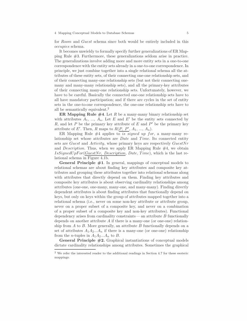
ER Mapping Rule #4. Let R be a many-many binary relationship setwith attributes A1, ..., An. Let E and E′ be the entity sets connected byR, and let P be the primary key attribute of E and P ′ be the primary keyattribute of E′. Then, R maps to R(P, P ′, A1, ..., An).
ER Mapping Rule #4 applies to is signed up for, a many-many re-lationship set whose attributes are Date and T ime. Its connected entitysets are Guest and Activity, whose primary keys are respectively GuestNrand Description. Thus, when we apply ER Mapping Rule #4, we obtainIsSignedUpFor(GuestNr, Description, Date, T ime), which is the last re-lational schema in Figure 4.1b.
General Principle #1. In general, mappings of conceptual models torelational schemas are about finding key attributes and composite key at-tributes and grouping these attributes together into relational schemas alongwith attributes that directly depend on them. Finding key attributes andcomposite key attributes is about observing cardinality relationships amongattributes (one-one, one-many, many-one, and many-many). Finding directlydependent attributes is about finding attributes that functionally depend onkeys, but only on keys within the group of attributes mapped together into arelational schema (i.e., never on some non-key attribute or attribute group,never on a proper subset of a composite key, and never on a combinationof a proper subset of a composite key and non-key attributes). Functionaldependency arises from cardinality constraints— an attribute B functionallydepends on another attribute A if there is a many-one (or one-one) relation-ship from A to B. More generally, an attribute B functionally depends on aset of attributes A1A2...An if there is a many-one (or one-one) relationshipfrom the n-tuples in A1A2...An to B.
General Principle #2. Graphical instantiations of conceptual modelsdictate cardinality relationships among attributes. Sometimes the graphical
2 We refer the interested reader to the additional readings in Section 4.7 for these esotericmappings.

6 David W. Embley and Wai Yin Mok
instantiations of conceptual models are insufficient to express all needed car-dinality relationships. In this case, we express the missing cardinality con-straints we need using a formal constraint language when one is defined forthe conceptual model or notes in the absence of a defined formal constraintlanguage.
General Principle #3. The following algorithm generally applies to allconceptual models.
Step 1 Group keys, which may be single-attribute keys or composite-attribute keys, into sets in which the keys in a set are all in a one-to-onecorrespondence with each other. (In practice, these key sets will often besingleton sets.)
Step 2 In each key set, designate one of the keys (or the only key) to bethe primary key for the key set.
Step 3 To each key set, add all directly dependent non-key attributes, plus,from among other key sets, the attributes of all directly dependent primarykeys.
Step 4 For each group of attributes formed in Step 3, select a name andform a relational schema. (Name selection is often obvious. Since keys arefor entity sets or relationship sets, we typically use the entity-set name orthe relationship-set name.)
If we apply General Principle #3 to the ER diagram in Figure 4.1a,Step 1 yields the set of key sets: {{Description}, {GuestNr}, {RoomNr,RoomName}, {GuestNr Description}}.1 In Step 2 we designate RoomNras the primary key for the key set {RoomNr, RoomName}. All other keysets are singleton sets and thus each key in these singleton sets is a primarykey. In Step 3 we group attributes, and in Step 4 we select names for theseattribute groups and form relational schemas. For the key set {Description},the only directly dependent attribute is Duration. Hence, we add it, yielding(Description, Duration). Based on the diagram in Figure 4.1a, the obvi-ous name for this attribute group is Activity. Thus, Activity(Description,Duration) becomes the relational schema for the key set {Description}. Thisis the first relational schema in Figure 4.1b. The key set {GuestNr} has twodirectly dependent attributes: Name and Address. Thus, with the additionof the obvious schema name, Guest(GuestNr, Name, Address) becomes therelational schema for the key set {GuestNr}. This is the second relationalschema in Figure 4.1b. The key set {RoomNr, RoomName} has three di-rectly dependent non-key attributes: Type and Rate from the entity set Roomand ExtraCharges since it is an attribute of occupies, the many-one rela-tionship set from Room to Guest. From among the other key sets, GuestNr
1 Here, we make use of the common set notation in the relational database literaturethat lets a sequence of attribute names designate a set. Thus, {GuestNr Description}is a key set with a single composite key consisting of two attributes whereas {RoomNr,RoomName} is a key set with two keys.
4 Mapping Conceptual Models to Database Schemas 7
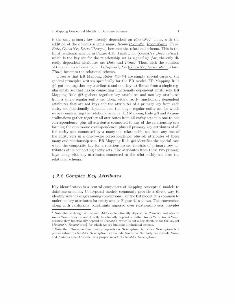
is the only primary key directly dependent on RoomNr.1 Thus, with theaddition of the obvious schema name, Room(RoomNr, RoomName, Type,Rate, GuestNr, ExtraCharges) becomes the relational schema. This is thethird relational schema in Figure 4.1b. Finally, for {GuestNr Description},which is the key set for the relationship set is signed up for, the only di-rectly dependent attributes are Date and T ime.2 Thus, with the additionof the obvious schema name, IsSignedUpFor(GuestNr, Description, Date,T ime) becomes the relational schema.
Observe that ER Mapping Rules #1–#4 are simply special cases of thegeneral principles written specifically for the ER model. ER Mapping Rule#1 gathers together key attributes and non-key attributes from a single reg-ular entity set that has no connecting functionally dependent entity sets. ERMapping Rule #2 gathers together key attributes and non-key attributesfrom a single regular entity set along with directly functionally dependentattributes that are not keys and the attributes of a primary key from eachentity set functionally dependent on the single regular entity set for whichwe are constructing the relational schema. ER Mapping Rule #3 and its gen-eralizations gather together all attributes from all entity sets in a one-to-onecorrespondence, plus all attributes connected to any of the relationship setsforming the one-to-one correspondence, plus all primary key attributes of allthe entity sets connected by a many-one relationship set from any one ofthe entity sets in a one-to-one correspondence, plus all attributes of thesemany-one relationship sets. ER Mapping Rule #4 identifies the special casewhen the composite key for a relationship set consists of primary key at-tributes of its connecting entity sets. The attributes from these two primarykeys along with any attributes connected to the relationship set form therelational schema.
4.2.2 Complex Key Attributes
Key identification is a central component of mapping conceptual models todatabase schemas. Conceptual models commonly provide a direct way toidentify keys via diagramming conventions. For the ER model, it is common tounderline key attributes for entity sets as Figure 4.1a shows. This conventionalong with cardinality constraints imposed over relationship sets provides
1 Note that although Name and Address functionally depend on RoomNr and also onRoomName, they do not directly functionally depend on either RoomNr or RoomNamebecause they functionally depend on GuestNr, which is not a key attribute for the key set{RoomNr, RoomName} for which we are building a relational schema.2 Note that Duration functionally depends on Description, but since Description is aproper subset of GuestNr Description, we exclude Duration. Similarly, we exclude Nameand Address since GuestNr is a proper subset of GuestNr Description.

8 David W. Embley and Wai Yin Mok
Room
Room Nr
Rate
has reservation
for Guest
is signed up
forActivity
Address Name
Description
Duration
Date
NrInParty
Date Tim e
Name Address Guest Room Nr Date Name Address Rate Name Address Date Tim e Description NrInParty
(a) ER Diagram.
Room(RoomNr)Guest(Name, Address)
Activity(Description, Duration)
HasReservationFor(RoomNr, Date, Name, Address, Rate)
IsSignedUpFor(Name, Address, Date, Time, Description, NrInParty)
(b) Generated Schemas.
Fig. 4.2 Mappings for Complex Key Attributes: ER Diagram and Generated Schemas.
sufficient information for identifying many keys for entity and relationshipsets — indeed most keys in practice.
ER diagramming conventions, however, are not sufficient to allow us toidentify all keys. Two common cases are (1) composite keys for entity sets and(2) keys for relationship sets not derivable from information about entity-setkeys coupled with relationship-set cardinality constraints. The ER diagramin Figure 4.2a. gives examples of these two cases.
1. The entity set Guest in Figure 4.2a has no key attribute. NeitherName alone nor Address alone uniquely identifies a guest. Many differentpeople with the same name may make reservations, and we may wishto make it possible for different people with the same address to makereservations. Name and Address together, however, may uniquely identifyGuest, and we may designate that this must hold in our database so thatName Address becomes a composite key. If no diagramming conventionor other formal convention provides a way to designate composite keys foran entity set,1 it is best to record this information in a note. In our noteshere, we use standard functional dependency (FD) notation, allowing bothattribute names and entity-set names to appear as components of left-hand
1 There are many ER variants, and some have conventions to designate composite keys forentity sets (e.g., a connecting line among underlined attributes of an entity set).
4 Mapping Conceptual Models to Database Schemas 9
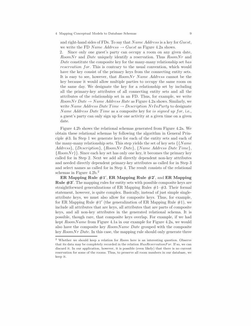
and right-hand sides of FDs. To say that Name Address is a key for Guest,we write the FD Name Address → Guest as Figure 4.2a shows.2. Since only one guest’s party can occupy a room on any given date,RoomNr and Date uniquely identify a reservation. Thus RoomNr andDate constitute the composite key for the many-many relationship set hasreservation for. This is contrary to the usual convention, which wouldhave the key consist of the primary keys from the connecting entity sets.It is easy to see, however, that RoomNr Name Address cannot be thekey because it would allow multiple parties to occupy the same room onthe same day. We designate the key for a relationship set by includingall the primary-key attributes of all connecting entity sets and all theattributes of the relationship set in an FD. Thus, for example, we writeRoomNr Date → Name Address Rate as Figure 4.2a shows. Similarly, wewrite Name Address Date T ime → Description NrInParty to designateName Address Date T ime as a composite key for is signed up for, i.e.,a guest’s party can only sign up for one activity at a given time on a givendate.
Figure 4.2b shows the relational schemas generated from Figure 4.2a. Weobtain these relational schemas by following the algorithm in General Prin-ciple #3. In Step 1 we generate keys for each of the entity sets and each ofthe many-many relationship sets. This step yields the set of key sets {{NameAddress}, {Description}, {RoomNr Date}, {Name Address Date T ime},{RoomNr}}. Since each key set has only one key, it becomes the primary keycalled for in Step 2. Next we add all directly dependent non-key attributesand needed directly dependent primary-key attributes as called for in Step 3and select names as called for in Step 4. The result consists of the relationalschemas in Figure 4.2b.2
ER Mapping Rule #1′, ER Mapping Rule #2′, and ER MappingRule #3′. The mapping rules for entity sets with possible composite keys arestraightforward generalizations of ER Mapping Rules #1–#3. Their formalstatement, however, is quite complex. Basically, instead of just simple single-attribute keys, we must also allow for composite keys. Thus, for example,for ER Mapping Rule #1′ (the generalization of ER Mapping Rule #1), weinclude all attributes that are keys, all attributes that are parts of compositekeys, and all non-key attributes in the generated relational schema. It ispossible, though rare, that composite keys overlap. For example, if we hadkept RoomName from Figure 4.1a in our example for Figure 4.2a, we wouldalso have the composite key RoomName Date grouped with the compositekey RoomNr Date. In this case, the mapping rule should only generate three
2 Whether we should keep a relation for Room here is an interesting question. Observethat its data may be completely recorded in the relation HasReservationFor. If so, we can
discard it. In our application, however, it is possible (even likely) that there is no currentreservation for some of the rooms. Thus, to preserve all room numbers in our database, wekeep it.

10 David W. Embley and Wai Yin Mok
attributes (not four) for these two composite keys. The single occurrence ofDate in the relational schema would be part of both composite keys.
ER Mapping Rule #4′. For any relationship set, we gather togetherall attributes constituting primary keys of all related entity sets plus all at-tributes of the relationship set. We then determine, from among these at-tributes, which attributes and attribute sets are keys. This becomes the re-lational schema for the relationship set, except in two special cases havingto do with ER Mapping Rules #2′ and #3′. If the primary key of one andonly one of the connected entity sets E of the relationship set R is a keyfor R, then as part of Mapping Rule #2′, all the attributes of the relationalschema for R become part of the relational schema for E; there is no separaterelational schema for R. If the primary keys of two or more of the connectedentity sets E1, ..., En of the relationship set R is each a key for R, then aspart of ER Mapping Rule #3′, all the attributes from the relational schemasfor E1, ..., En, and R are all combined to form a single relational schema forthe database.
4.2.3 Recursive Relationship Sets & Roles
To be understood, recursive relationship sets require roles. Figure 4.3a showsan example. The role Connecting Room helps us understand that the rela-tionship set denotes adjoining rooms with a doorway between them: a Roomis connected with a Connecting Room.
ConnectingRoom
Room
RoomNr
Type
is connectedwith
(a) ER Diagram.
Room(RoomNr, Type)IsConnectedWith(RoomNr, ConnectingRoomNr)
(b) Generated Schemas.
Fig. 4.3 Mappings for Roles: ER Diagram and Generated Schemas.
Roles also help us choose attribute names for recursive relationship sets.We map a recursive relationship set to a relational schema in the same way wemap regular relationship sets to a relational schema. One-one and many-one

4 Mapping Conceptual Models to Database Schemas 11
recursive relationship sets become part of the relational schema for the entityset, and many-many recursive relationship sets become relational schemas bythemselves. In all cases, however, there is one difference — we must renameone (or both) of the primary-key attributes. Because the regular mappingfor a recursive relationship set would make the primary key of the entity setappear twice, and since a relational schema cannot have duplicate attributenames, we must rename one (or both) of them. The role helps because it usu-ally gives a good clue about what one of the names should be. As Figure 4.3bshows, we map the many-many recursive relationship set to the relationalschema with attribute names RoomNr and ConnectingRoomNr.
We can also use roles in this same way even when a relationship set isnot recursive. For example, we could have added a role Occupied Room tothe Room side of occupies in the ER diagram in Figure 4.1a. In this casewe could have generated Room(OccupiedRoomNr, OccupiedRoomName,Type, Rate, GuestNr, ExtraCharges) in which OccupiedRoomNr replacesRoomNr and OccupiedRoomName replaces RoomName in the relationalschema in Figure 4.1b. Using the role name in this way is optional, but maybe useful for distinguishing the roles attributes play when we have more thanone relationship set between the same two entity sets. For example, we couldhave also had has reservation for in addition to occupies as a relationshipset between Room and Guest in Figure 4.1a.
4.2.4 Weak Entity Sets
A weak entity set is an entity set with no key among its directly associatedattributes. If we augment our bed and breakfast example to a chain of bed andbreakfast establishments as Figure 4.4a shows, the room number no longeruniquely identifies a room. Every bed and breakfast in the establishmentlikely has a Room #1 and a Room #2 and probably more. Thus, Room hasno key among its directly associated attributes, and it becomes a weak entityset.
In an ER diagram, we designate a weak entity set by enclosing the name ofthe weak entity set in a double box. In addition, we add a special relationshipset connecting the weak entity set to the entity set on which the weak entityset depends for its key. We designate these special relationship sets by adouble diamond and by adding an arrowhead on the side connecting to theentity set on which the weak entity set depends. Adding the arrowhead isappropriate since there is always a many-one relationship from the weakentity set to the entity set on which the weak entity set depends. The ERmodel does not, by the way, preclude the entity set on which a weak entityset depends from itself being a weak entity set.
Figure 4.4a is an ER diagram showing the three situations in which we nor-mally find weak entity sets. Weak entity sets typically arise (1) when there is

12 David W. Embley and Wai Yin Mok
is for
is forRoom Room Nr
Type
Guest
Activity
GuestNr
NrPersons
Name
Description
Duration
BedAndBreakfast
is for Reservation
Nam e
Location
YearOpened
GuaranteeNr
Date Time Age
Person Activity
Registration
Name Location BedAndBreakfast Name Location RoomNr Room GuestNr Nam e Person GuestNr Nam e Date Time ActivityRegistration
(a) ER Diagram.
BedAndBreakfast(Name, Location, YearOpened)
Room(Name, Location, RoomNr, Type)
Reservation(GuaranteeNr, Name, Location, RoomNr, GuestNr)
Guest(GuestNr, NrPersons)
Person(GuestNr, Name, Age)
Activity(Description, Duration)
ActivityRegistration(GuestNr, Name, Date, Time, Description)
(b) Generated Schemas.
Fig. 4.4 Mappings for Weak Entity Sets: ER Diagram and Generated Schemas.
an organizational subdivision (e.g., Room is an organizational division of theBedAndBreakfast chain), (2) when one entity depends on the existence ofanother (e.g., for the bed and breakfast database, Person depends on the ex-istence of a registered Guest), and (3) when we wish to view relationship setsas entity sets (e.g., an Activity Registration rather than just a relationshipset between Person and Activity).1
The general principles tell us how to map weak entity sets to relationalschemas. We first identify keys. In every case in which we find a weak entityset, the identity of entities in the weak entity set depends on the key for someother one or more entity sets. The identity of a room depends on the bedand breakfast in which the room is located. The key for BedAndBreakfast,
1 Note, by the way, that the entity set Reservation is not weak, even though it is certainlya relationship set we view as an entity set. When we turned it into an entity set, we gaveit a key, GuaranteeNr, so that it did not become a weak entity set.

4 Mapping Conceptual Models to Database Schemas 13
which for our example is the composite key Name Location,2 plus a RoomNruniquely identify a room. Thus, the key for Room is the composite of all threeattributes, namely, Name Location RoomNr. For Person, names are notunique identifiers, but are usually unique within a family, which often con-stitutes a registered guest’s party. In our example, we require unique nameswithin a registered guest’s party, and thus the key for the weak entity setPerson is the composite of GuestNr and Name (of Person). A personcan sign up for only one activity at a given time on a given date. Thus,to uniquely identify an ActivityRegistration, we need the key of Person,which is GuestNr Name, as well as Date and T ime to all be part of the key.Thus, the composite key for ActivityRegistration is GuestNr Name DateT ime.
After identifying keys for a weak entity set (and designating one tobe the primary key in case there are several), we add all directly depen-dent non-key attributes and directly dependent primary-key attributes. Wethen choose a name — usually the name of the weak entity set— and forma relational schema. Figure 4.4b shows the result for the ER diagram inFigure 4.4a. For the weak entity set Room, the only directly dependentattribute is Type. Thus, since the key is the composite Name LocationRoomNr, the relational schema is Room(Name, Location, RoomNr, Type),the second relational schema in Figure 4.4b. Similarly, for Person, sinceAge is the only directly dependent attribute, the relational schema for theweak entity set is Person(GuestNr, Name, Age). For the weak entity setActivityRegistration, Description is a directly dependent primary-key at-tribute. Thus, since the composite key is GuestNr Name Date T ime, wegenerate the last relational schema in Figure 4.4b.
ER Mapping Rule #5. Let W be a weak entity set, let E, entity seton which W depends (E may itself be weak), and let F1, ..., Fm be the mother entity sets (if any) in a many-one relationship from W to Fi (1 ≤i ≤ m). Form a relational schema called W with attributes consisting ofall the attributes of W , the primary-key attribute(s) of E, all the primary-key attributes of F1, ..., Fm, and all the attributes (if any) of the many-onerelationship sets from W to each Fi (1 ≤ i ≤ m). From among the attributes,determine the keys for W and designate one as the primary key. Each key ofW is formed from by adding one or more attributes of W to the primary keyfor E.3
2 Location is meant to be a simple city or town or other designated place. Sev-eral bed and breakfast establishments can be in the same location (e.g., Boston),but each establishment in the same location must have a different name. Thus,Name Location → BedAndBreakfast.3 Typically, as in our examples here, W has only one key. But, for example, if we also hadRoomName for the weak entity set Room, we would have a second key for Room, namelyName Location RoomName.
14 David W. Embley and Wai Yin Mok
Room
Room Nr
Rate
has reservation
for Guest
is signed up
forActivity
Name Description Duration
Date RoomNr Date GuestNrRate
Current Guest
Future Guest
HighCost Activity
Single
Double
Suite
GuestNr
Free Activity
ReturningGuest
CreditCardNr CreditCard Expiration
ExtraCharges NrOfReservations
Discount
Cost
DownPaym ent
Advance Reservation Requirement
EquipmentDeposit
Notification Requirement
(a) ER Diagram.
Room(RoomNr, RoomType)
Guest(GuestNr, Name, ExtraCharges?, CreditCardNr?, CreditCardExpiration?,
NrOfReservations?, Discount?)Activity(Description, Duration)
HighCostActivity(Description, Cost, DownPayment, AdvanceReservationRequirement)
FreeActivity(Description, EquipmentDeposit, NotificationRequirement)
HasReservationFor(RoomNr, Date, GuestNr, Rate)
IsSignedUpFor(GuestNr, Description)
(b) Generated Schemas.
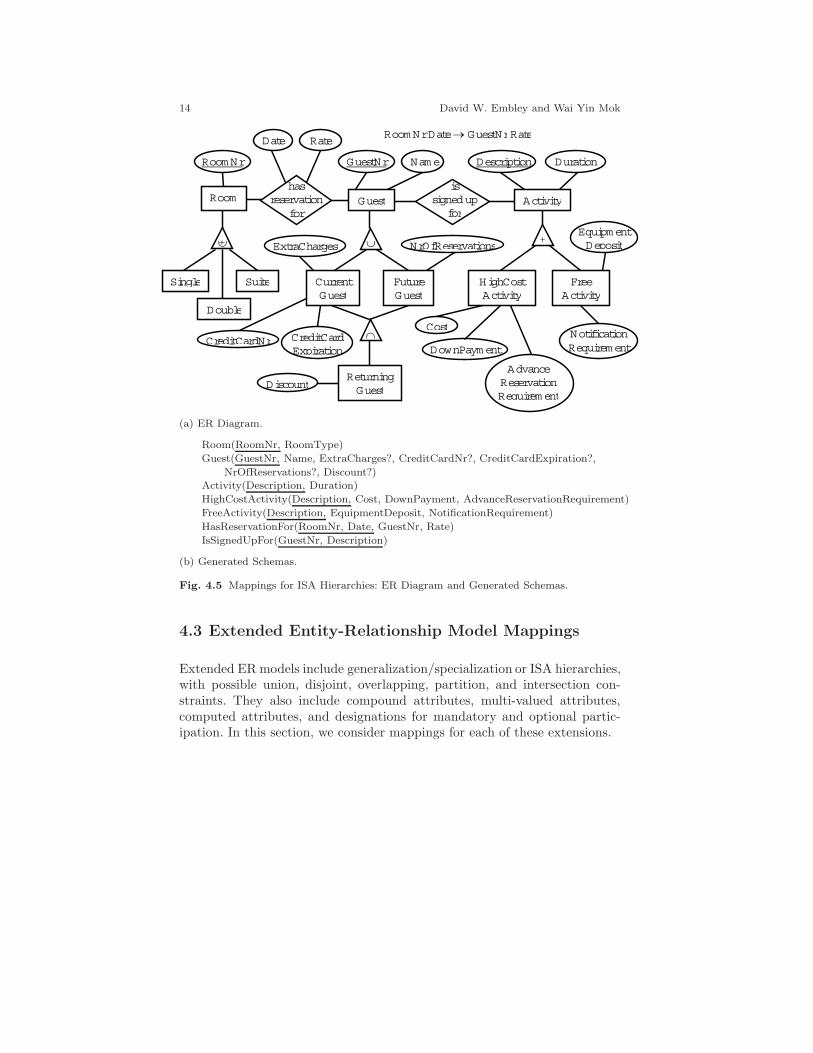
Fig. 4.5 Mappings for ISA Hierarchies: ER Diagram and Generated Schemas.
4.3 Extended Entity-Relationship Model Mappings
Extended ER models include generalization/specialization or ISA hierarchies,with possible union, disjoint, overlapping, partition, and intersection con-straints. They also include compound attributes, multi-valued attributes,computed attributes, and designations for mandatory and optional partic-ipation. In this section, we consider mappings for each of these extensions.
4 Mapping Conceptual Models to Database Schemas 15
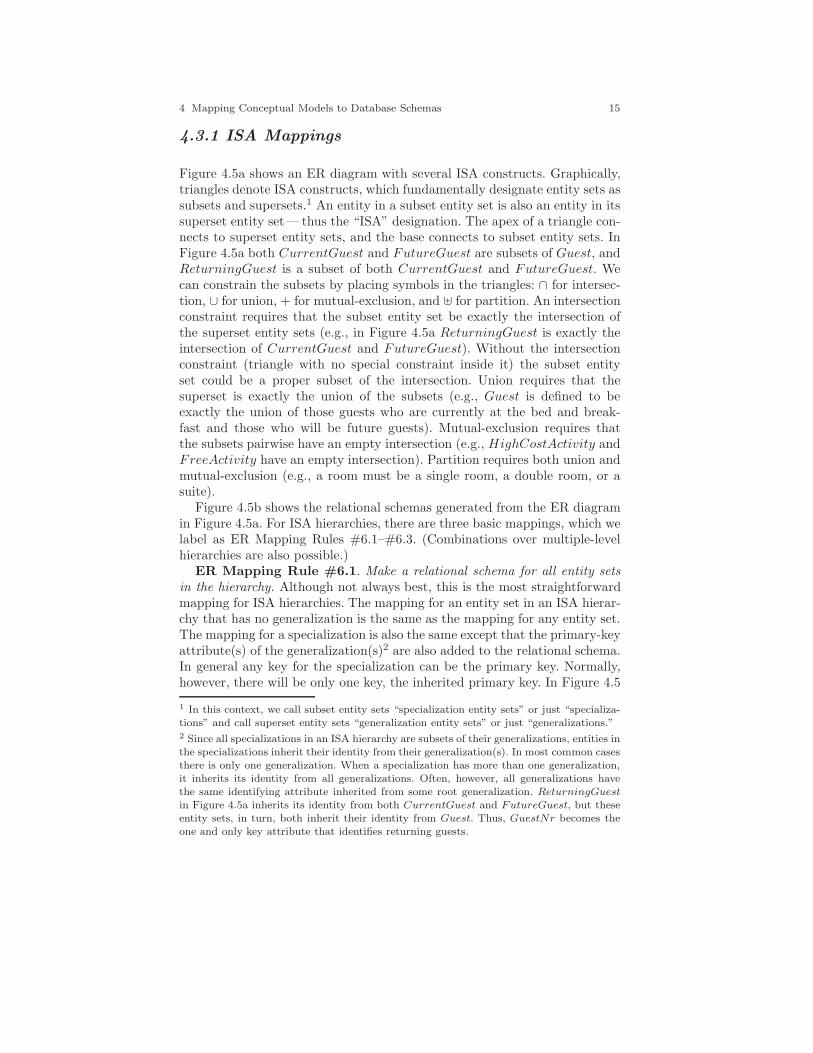
4.3.1 ISA Mappings
Figure 4.5a shows an ER diagram with several ISA constructs. Graphically,triangles denote ISA constructs, which fundamentally designate entity sets assubsets and supersets.1 An entity in a subset entity set is also an entity in itssuperset entity set—thus the “ISA” designation. The apex of a triangle con-nects to superset entity sets, and the base connects to subset entity sets. InFigure 4.5a both CurrentGuest and FutureGuest are subsets of Guest, andReturningGuest is a subset of both CurrentGuest and FutureGuest. Wecan constrain the subsets by placing symbols in the triangles: ∩ for intersec-tion, ∪ for union, + for mutual-exclusion, and � for partition. An intersectionconstraint requires that the subset entity set be exactly the intersection ofthe superset entity sets (e.g., in Figure 4.5a ReturningGuest is exactly theintersection of CurrentGuest and FutureGuest). Without the intersectionconstraint (triangle with no special constraint inside it) the subset entityset could be a proper subset of the intersection. Union requires that thesuperset is exactly the union of the subsets (e.g., Guest is defined to beexactly the union of those guests who are currently at the bed and break-fast and those who will be future guests). Mutual-exclusion requires thatthe subsets pairwise have an empty intersection (e.g., HighCostActivity andFreeActivity have an empty intersection). Partition requires both union andmutual-exclusion (e.g., a room must be a single room, a double room, or asuite).
Figure 4.5b shows the relational schemas generated from the ER diagramin Figure 4.5a. For ISA hierarchies, there are three basic mappings, which welabel as ER Mapping Rules #6.1–#6.3. (Combinations over multiple-levelhierarchies are also possible.)
ER Mapping Rule #6.1. Make a relational schema for all entity setsin the hierarchy. Although not always best, this is the most straightforwardmapping for ISA hierarchies. The mapping for an entity set in an ISA hierar-chy that has no generalization is the same as the mapping for any entity set.The mapping for a specialization is also the same except that the primary-keyattribute(s) of the generalization(s)2 are also added to the relational schema.In general any key for the specialization can be the primary key. Normally,however, there will be only one key, the inherited primary key. In Figure 4.5
1 In this context, we call subset entity sets “specialization entity sets” or just “specializa-tions” and call superset entity sets “generalization entity sets” or just “generalizations.”2 Since all specializations in an ISA hierarchy are subsets of their generalizations, entities inthe specializations inherit their identity from their generalization(s). In most common casesthere is only one generalization. When a specialization has more than one generalization,it inherits its identity from all generalizations. Often, however, all generalizations havethe same identifying attribute inherited from some root generalization. ReturningGuestin Figure 4.5a inherits its identity from both CurrentGuest and FutureGuest, but theseentity sets, in turn, both inherit their identity from Guest. Thus, GuestNr becomes theone and only key attribute that identifies returning guests.

16 David W. Embley and Wai Yin Mok
we map the ISA hierarchy rooted at Activity in this way. The relationalschema for Activity in Figure 4.5b is the same as it would be without theISA hierarchy. HighCostActivity and FreeActivity, however, both inheritthe primary key Description from Activity and include it as the primary keyfor their relational schemas along with all directly dependent attributes.
ER Mapping Rule #6.2. Make a relational schema for only root entitysets. For this mapping, we collapse the entire ISA hierarchy to the entity setof the root generalization,3 so that all attributes of specializations becomeattributes of the root and all relationship sets associated with specializationsbecome relationship sets associated with the root. We then map this singleentity set to a relational schema in the usual way. After doing the mapping,we determine which attributes are nullable. All attributes that would not havebeen in the mapping if we had not collapsed the ISA hierarchy are nullable.In our relational schemas, we mark nullable attributes with a question mark.When we transform generic relational schemas to SQL create statements forimplementation, we allow nullable attributes to have the value NULL; non-nullable attributes may not have the value NULL. In Figure 4.5 we map theISA hierarchy rooted at Guest in this way. When collapsing the ISA hierarchy,the attributes of the three specializations, all become nullable attributes ofGuest. As Figure 4.5b shows, these five attributes all have an appendedquestion mark.
We might wonder if this mapping causes us to lose track of which guestsare current guests, which are future guests, and which are returning guests.For this example we do not lose the information. According to the seman-tics of the ER model instance in Figure 4.5a only returning guests will haveDiscount values whereas current and future guests who are not returningguests will not have Discount values. Future guests will have a value forNrOfReservations whereas current guests will not. Similarly, current guestswill have extra charges, credit card numbers, and credit card expirationswhereas future guests will not. Sometimes, however, it is not possible to knowthe specialization categories based on attribute values, and even when it ispossible, we may wish to have a way to record the specialization categories.The following two additions to Mapping Rule #6.2 show us how we can pro-vide attributes in which we can record this information about specializations.
• ER Mapping Rule #6.2a. Add a new attribute for each specialization.When mapping the generalization entity set to a relational schema, gen-erate an additional attribute for every specialization entity set. Valuesfor these attributes are Boolean, saying for each record of the relationalschema whether the entity the record represents is or is not in the spe-cialization. If we were to add these additional attributes for Guest, therelational schema for Guest in Figure 4.5b would instead be:
Guest(GuestNr, Name, ExtraCharges?, CreditCardNr?,
3 Although rare, if there are multiple roots, we collapse the hierarchy to all roots. Anyentity set that is the specialization of multiple roots collapses to all of them.

4 Mapping Conceptual Models to Database Schemas 17
CreditCardExpiration?, NrOfReservations?, Discount?,CurrentGuest, FutureGuest, ReturningGuest)
If we wish, we could omit ReturningGuest and just compute its value fora record as yes if both values for CurrentGuest and FutureGuest are yesand as no otherwise.
• ER Mapping Rule #6.2b. Add only one new attribute representing allspecializations. This mapping only applies when the specializations aremutually exclusive. If so, when mapping the generalization entity set toa relational schema, we only need to generate one additional attribute torepresent all specializations. The specialization entity-set names can bethe values for this new attribute. In Figure 4.5a, Room has three mutuallyexclusive specializations that designate the room type. We therefore gen-erate a new attribute, RoomType, for the generalization entity set Room.The values for this attribute can be the names of the specialization en-tity set. The generated relational schema for Room in Figure 4.5b hasthe attributes RoomNr and RoomType. Values for RoomType would be“Single”, “Double”, and “Suite” or any other designating value to saythat the room is a single room, a double room, or a suite.
ER Mapping Rule #6.3. Make a relational schema for only the leavesin the hierarchy. The leaf entity sets inherit all attributes and all relationshipsets from parents along a path all the way back to the root.3 This mappingonly applies when union constraints are present all along all paths. If a unionconstraint were missing, there could be members of the entity sets in thehierarchy that would not appear in the leaf entity sets and thus would belost in the implementation. Further, we usually only apply this mappingwhen mutual-exclusion is also present along all paths. If not, then membersof the entity sets could appear in more than one leaf entity set and thus wouldappear as duplicates in the implementation, once for each leaf entity set inwhich a member appears. As an example, assume that there are only high-costactivities and free activities and thus that the constraint for the ISA hierarchyrooted at Activity in Figure 4.5a is a partition (�) constraint rather thana mutual-exclusion (+) constraint. Applying the mapping in which we onlyrepresent the leaves of the ISA hierarchy, we would replace the three relationalschemas Activity, HighCostActivity, and FreeActivity in Figure 4.5b by thefollowing two relational schemas:
HighCostActivity(Description, Duration, Cost, DownPayment,
AdvanceReservationRequirement)FreeActivity(Description, Duration, EquipmentDeposit,
NotificationRequirement)
Observe that both HighCostActivity and FreeActivity include the at-tribute Duration as well as Description and that the connection to theIsSignedUpFor relational schema is accounted for through the Description
3 If there are multiple roots, the leaves inherit from all roots.

18 David W. Embley and Wai Yin Mok
attributes. When we make a relational schema for only the leaves in an ISAhierarchy, we must account for all attributes and relationship-set connectionsof all ancestors of each leaf entity set.
General Principle #4. Map ISA hierarchies to relational schemas bychoosing to make a relational schema for (1) all entity sets in an ISA hierar-chy, (2) only root entity sets, or (3) only leaf entity sets. Although there areguidelines that typically indicate which of the three mappings to use, makingthe best choice is often application dependent. Deciding among the possibil-ities depends on the ISA constraints and the number of attributes involved.Designers use the following rule-of-thumb guidelines.
• Select (1) when the generalizations and specializations all have many at-tributes.
• Select (2) when the specializations collectively have few attributes.• When the specializations have no attributes, select (2a) either for an ISA
union constraint or for an ISA with no constraint.• When the specializations have no attributes, select (2b) either for an ISA
partition constraint or for an ISA mutual-exclusion constraint.• Select (3) for an ISA partition constraint, especially when there are many
attributes for the specializations and few for the generalizations.
Often there is no obvious best choice. In this case the developer must chooseone. Furthermore, in some complex cases, especially with large hierarchies, itmay be best to make a separate choice for each individual ISA configurationin the hierarchy. In the end the mappings must account for representing allpossible entities in every entity set in the ISA hierarchy and all possiblerelationships and attributes of these entities.
4.3.2 Mappings for Complex Attributes
Extended ER models allow for several types of complex attributes. Fig-ure 4.6a includes examples for each type.
• A multi-valued attribute is an attribute whose values are sets of values. Inan extended ER diagram, we denote a multi-valued attribute by a doubleoval. In Figure 4.6, ActivityInterest is a multi-valued attribute. Guestsmay be interested in several activities— one guest may be interested in theset of activities {golf, horseback riding, canoeing} while another guest maybe interested in the set of activities {chess, hiking, canoeing}. V iew is alsoa multi-valued attribute, whose sets might be {Ocean, CityOverlook} orjust {Ocean} depending on what can be seen by looking out the window(s)of a room in the bed and breakfast establishment.
• A compound attribute is an attribute with component parts each of whichis also an attribute. In an extended ER diagram, we denote compound at-tributes by attaching component attributes directly to the compound at-

4 Mapping Conceptual Models to Database Schemas 19
Room
RoomNr
Guest
Address Nam e
ActivityInterest
NameAndAddress
StreetNr
Rate City
StateOrCountry
PostalCode
Discount
has reservation
for
Date
RackRate View
Currency
RoomNr Date Guest (Date Room).Rate = (1 – GuestNr.Discount/100)Room.RackRate Currency.FCAmount = (1 + Fee/100)[Amount]Currency.ExchangeRate
FCAmount Fee
Foreign Currency Rate
Exchange Rate
GuestNr
View: Ocean, M ountain, CityOverlook
(a) ER Diagram.
Guest(GuestNr, Name, StreetNr, City, StateOrCountry, PostalCode, Discount)
GuestActivityInterest(GuestNr, ActivityInterest)
Room(RoomNr, RackRate, Ocean, Mountain, CityOverlook)
HasReservationFor(RoomNr, Date, GuestNr, Rate)
ForeignCurrencyRate(Currency, ExchangeRate)
Fee(Fee)
(b) Generated Schemas.
Fig. 4.6 Mappings for Complex Attributes: ER Diagram and Generated Schemas.
tribute. In Figure 4.6a, NameAndAddress is a compound attribute whosecomponent attributes are Name and Address. The component attributeAddress is also compound; its component attributes are StreetNr, City,StateOrCountry, and PostalCode.
• A computed attribute is an attribute whose value can be computed. In anextended ER diagram, we denote a computed attribute by a dashed oval.In Figure 4.6a, FCAmount and Rate are computed attributes.
• An entity-set attribute, called in other contexts a class attribute, is anattribute whose value is the same for all entities in the entity set and thuscan be thought of as applying to the entire set of entities rather than eachindividual entity in the set. In an extended ER diagram, we denote anentity-set attribute by a small circle. In Figure 4.6a, Fee is an example.

20 David W. Embley and Wai Yin Mok
It is a percentage and is meant to be the fee collected by the bed andbreakfast establishment for accepting payment in a foreign currency.
Figure 4.6b shows how we map the various complex attributes in Fig-ure 4.6a to relational schemas. Basically, the mappings are straightforwardapplications of the general principles. The cardinality constraints for multi-valued attributes make them have the properties of many-many relationshipsets. The collapsing of compound-attribute trees make the leaves of thesetrees have the properties of directly dependent attributes. Computed at-tributes are the same as regular attributes except we may not need to storethem. Although entity-set attributes could be treated as regular attributes,their singleton property makes them amenable to a different kind of mapping,making entity-set attributes an exception to the general principles.
ER Mapping Rule #7. Fundamentally, multi-valued attributes are ina many-many relationship with the entity set to which they are connected.Each entity in an entity set E with a multi-valued attribute A relates to nvalues v1, ..., vn of A, and each value of A relates to m entities e1, ..., em inE. Thus, unless the number of values in A, |A|, is fixed and small, we treatA as if it were another entity set E′ in a many-many relationship with E;E′’s only attribute, and therefore its primary-key attribute, is A. When |A|is fixed and small, it is possible to treat it as |A| attributes v1, ..., v|A| of E,whose values are Boolean stating whether an entity e relates to that value ordoes not relate to that value.
• ER Mapping Rule #7a. If entity set E has a multi-valued attribute A,then if P is the primary key of E, generate the relational schema N(P, A).If the primary key of E happens to be composite, P represents the attributelist for the composite primary key. N is a chosen name—often a con-catenation of the name of E and the name of A. The relational schemaGuestActivityInterest in Figure 4.6b is an example. A guest can be in-terested in may different activities, and an activity can be of interest tomany different guests. Thus, since GuestNr is the primary key of Guest,we generate GuestNr and ActivityInterest as the attributes and as thecomposite key for the relational schema.
• ER Mapping Rule #7b. As an exception to ER Mapping Rule #7a, ifentity set E has a multi-valued attribute A, n is the size of A, and n is fixedand small, then if A = {V1, ..., Vn}, add V1, ..., Vn as Boolean attributesto the relational schema formed for E. The relational schema Room inFigure 4.6b is an example. As specified in a note in the diagram, a roomcan have only up to three views (Ocean, Mountain, or CityOverlook).Thus, for the multi-valued attribute V iew of Room, we add these threeview names, Ocean, Mountain, and City as attributes to the relationalschema. Values for these attributes are Boolean: if a front corner room hasall three views, all three attribute values would have the value yes, and ifa back center room looks out only on the mountains, the Mountain valuewould be yes and the Ocean and cityOverlook values would be no.

4 Mapping Conceptual Models to Database Schemas 21
ER Mapping Rule #8. Treat each leaf attribute of a compound attributetree T of an entity set E as an attribute of E; then map E in the usual way.In addition, if any non-leaf node N of T is a key for E, form a compositekey from the leaf attributes of the subtree rooted at N . In Figure 4.6a Guesthas a compound attribute NameAndAddress. Its leaf attributes are Name,StreetNr, City, StateOrCountry, and PostalCode. Thus, for Guest we forma relational schema with these attributes along with the regular attributesGuestNr and Discount. (Being multi-valued, ActivityInterest is not a reg-ular attribute and is not included — neither are the non-leaf attributes of thecompound attribute tree, NameAndAddress and Address.) Further, sincethe non-leaf attribute NameAndAddress is a key for Guest, we form a com-posite key from all its leaf attributes as Figure 4.6b shows.
ER Mapping Rule #9. If a computed attribute is to be stored in thedatabase, treat it as a regular attribute for the purpose of mapping it to arelational schema. When values for attributes are computed, we may or maynot want to store their values in the database. If computed values serve toinitialize a field and the field value may later change, we store the values.In this case, there must be an attribute for it in the generated relationalschema. On the other hand, if the value is computed from other existingvalues whenever we need it, we need not store it. In this case, we ignore itwhen generating relational schemas. In our example in Figure 4.6a, Rate isan initial value, which depends on a guest’s discount and the room’s rack ratebut which can be set to another value. Thus, we generate an attribute forRate in the relational schema for HasReservationFor, the place it would goif it were a regular attribute. FCAmount, however, is only computed whena guest wants to know how much to pay if the amount owed is to be paid ina foreign currency. Thus, we do not generate an attribute for FCAmount inany relational schema.
ER Mapping Rule #10. For an entity-set attribute A, we either ig-nore it or map it to a single-attribute, single-valued relation A(A). Valuesfor entity-set attributes may be constants established in the program code,may be values accepted as input values when needed, or may be stored in thedatabase and updated occasionally. In our example, we store the fee valueas a percentage number in the database and thus need the relational schemaFee(Fee) as Figure 4.6b shows.
4.3.3 Mappings for Mandatory/Optional Participation
Figure 4.7a illustrates mandatory and optional participation in an ER di-agram. We designate optional participation by placing a small “o” near aconnection for attributes and relationship sets, and we designate mandatoryparticipation by the absence of an “o.” Optional participation for an attributeA means that an entity in an entity set need not have a value for A; manda-

22 David W. Embley and Wai Yin Mok
has favorite
Room
Room Nr
Type
occupies Guest
GuestNr
Address Name
Rate
has reservation
for
Date
RoomNr Date Guest
(a) ER Diagram.
RoomAndOccupant(RoomNr, Type, GuestNr?)
GuestAndFavoriteRoom(GuestNr, Name, Address?, RoomNr?)
HasReservationFor(RoomNr, Date, GuestNr, Rate)
(b) Generated Schemas.
Fig. 4.7 Mappings for Mandatory/Optional Constructs: ER Diagram and GeneratedSchemas.
tory participation means that an entity must have a value. In Figure 4.7a aGuest need not provide an Address when registering (i.e., the database sys-tem will allow the Address field in a record for a Guest to be null). Optionalparticipation for a relationship set R means that an entity in an entity setneed not participate in the relationship set; mandatory participation meansthat it must participate. For example, a Room in Figure 4.7a need not beoccupied, need not be anyone’s favorite, and need not be reserved by any-one. Similarly, someone recorded as a Guest in the database need not havea reservation, need not occupy a room, and need not have a favorite room.The database would allow, for example, a record to be kept for someone whohad been a guest, but is not currently occupying a room, has no reservation,and has no particular favorite room.
Figure 4.7b shows how we consider optionality when we map to relationalschemas. As before, the question mark means that an attribute is nullable.When attributes are optional, they are nullable; when they are mandatory,they are not nullable. Thus, for example, Address has an appended ques-tion mark in GuestAndFavoriteRoom whereas Name does not. When at-tributes of a relationship set plus the primary-key attributes of the associ-ated entity sets are mapped into a relational schema for an entity set, ifparticipation in the relationship set is optional, these imported attributesare all nullable. When participation is mandatory, these attributes are notnullable. Thus, for example, GuestNr is nullable in RoomAndOccupant. Be-

4 Mapping Conceptual Models to Database Schemas 23
cause occupies is many-one from Room to Guest, the primary key for Guest,which is GuestNr, becomes one of the attributes of RoomAndOccupant, andbecause participation of a Room in the occupies relationship set is optional,GuestNr is imported as a nullable attribute. Similarly, RoomNr is nullablein GuestAndFavoriteRoom since the has favorite relationship set is many-one from Guest to Room and Guest optionally participates in has favorite.Observe that the relationship set has reservation for is many-many and isnot imported into either Room or Guest. Thus, there is no special mappingbased on the optionality of reservations for rooms and guests.
ER Mapping Rule #11. Mark all nullable attributes in generated re-lational schemas. Attributes that are the primary key of a relational schemaor that are in the composite primary key of a relational schema are nevernullable. All other attributes may be nullable and should be so marked if theirvalue for a record can be NULL.
This rule is a little different from all other rules. It is written with respectto generated schemas. Thus, it does not say how to generate schemas, neitherdoes it say exactly how to decide which attributes are nullable. Rather, it sayswhich attributes are and are not potentially nullable, and it says that amongthose that are potentially nullable the database designer should decide whichones should allow null values. The reason for writing the rule this way istwofold:
1. Many ER diagrams never specify mandatory/optional participation(sometimes because the notation does not allow it, and sometimes just be-cause it is not commonly done). Thus the nullable properties of attributesin relational schemas are often not derivable from the ER diagram.2. When mandatory/optional participation can be specified in an ERdiagram, even if someone specifies that an attribute that turns out tobe part of the primary key of some relational schema should be nullable,it cannot be nullable. Relational database systems do not allow nulls inprimary keys.
To illustrate Reason #1, we can consider the ER diagrams in Figures 4.1–4.6 in which no optional participation explicitly appears. One view we cantake for all these diagrams is that there is no optional participation. In thiscase, all generated relational schemas remain as they are. This point of view,however, does say something about the semantics of the schemas. For exam-ple, in the Room schema in Figure 4.1b, we can only record room numbers,type, and rate for occupied rooms. If we want to store this information forunoccupied rooms, we would be forced to enter some bogus GuestNr (e.g.,−1) and some bogus value for ExtraCharges (e.g., 0). It may be better tosimply allow these attributes to be nullable. The same is true for addressof a guest in the Guest schema in Figure 4.1b. Even if the guest is in theprocess of moving and has no address to give, or if the guest refuses to givean address, something (e.g., “none”) must be entered.

24 David W. Embley and Wai Yin Mok
To illustrate Reason #2, consider what it would mean if RoomNr forRoomAndOccupant in Figure 4.7b were marked as optional and thus allowedto be nullable. This means that some rooms would have no identifier— noroom number. Suppose we try to store information about several no-numberdouble rooms that currently have no occupants. Even if the database wouldlet us store the room number as null, we would have trouble since we couldnot distinguish the rooms from one another. We would not even know howmany unoccupied double rooms we have. This motivates the rule: Attributesof primary keys in a relational schema may not be null. Note that this ruledoes not say that key attributes cannot be null — only that primary-key at-tributes cannot be null. Suppose, for example, that a guest can have a guar-antee number (GuaranteeNr) that uniquely identifies the guest in additionto a guest number (GuestNr). We could then add GuaranteeNr as a key at-tribute to the attributes already in GuestAndFavoriteRoom in Figure 4.7band let it be nullable so that not all guests would have to have a guaranteenumber. Note also that this rule does not say that primary-key attributesimported into a relational schema cannot be null. Indeed, GuestNr is nul-lable in RoomAndOccupant, where it is not the primary key, even though itis the primary key for GuestAndFavoriteRoom.
General Principle #5. Make attributes nullable if they can have NULLas their value. Attributes of primary keys in a relational schema are notnullable.
4.4 UML Mappings
In this section, we explain how to generate relational schemas from UMLclass diagrams. We base our procedure on the general principles, and thusthis explanation serves as an example of how to develop mapping rules tomap any conceptual model to relational schemas. In general, we first needto understand the syntactic features of the conceptual model and determinewhich corresponding ER features or extended ER features they denote. Wecan then map them to relational schemas in the same way we map ER featuresto relational schemas.
We illustrate our UML mappings using the class diagram in Figure 4.8 asan example. We begin by pointing out several syntactic features of this classdiagram and explain how they correspond to (extended) ER features. First,UML does not provide a graphical notation for specifying keys.4 UML does,however, provide an Object Constraint Language (OCL), in which we canexpress FDs. Figure 4.9 shows an example of how to specify the FD namelocation → BedAndBreakfast. Thus, to derive keys of classes in a class di-
4 UML does not use underlines to denote keys for classes; rather it uses underlines todenote static attributes —attributes that belong to classes, not attributes applicable toinstances of classes.
4 Mapping Conceptual Models to Database Schemas 25
1
2..*
1..*
1
1 1
1
*
*
*
*
*
*
*
*
{incomplete, disjoint}
connecting Room
BedAndBreakfast name location yearOpened
Reservation
rate = calcRate( ) calcRate( )
DateDiscount
date discount
M ailingAddress
name streetNr city stateOrCountry postalCode
Room
roomNr type rackRate
FavoriteRoom Activity
description duration
Guest
guestNr nameAndAddress: M ailingAddress nrPersons activityInterest [0..*]
Activity Registration
date time
Person
name age [0..1]
HighCost Activity
Free Activity
Fig. 4.8 UML Class Diagram
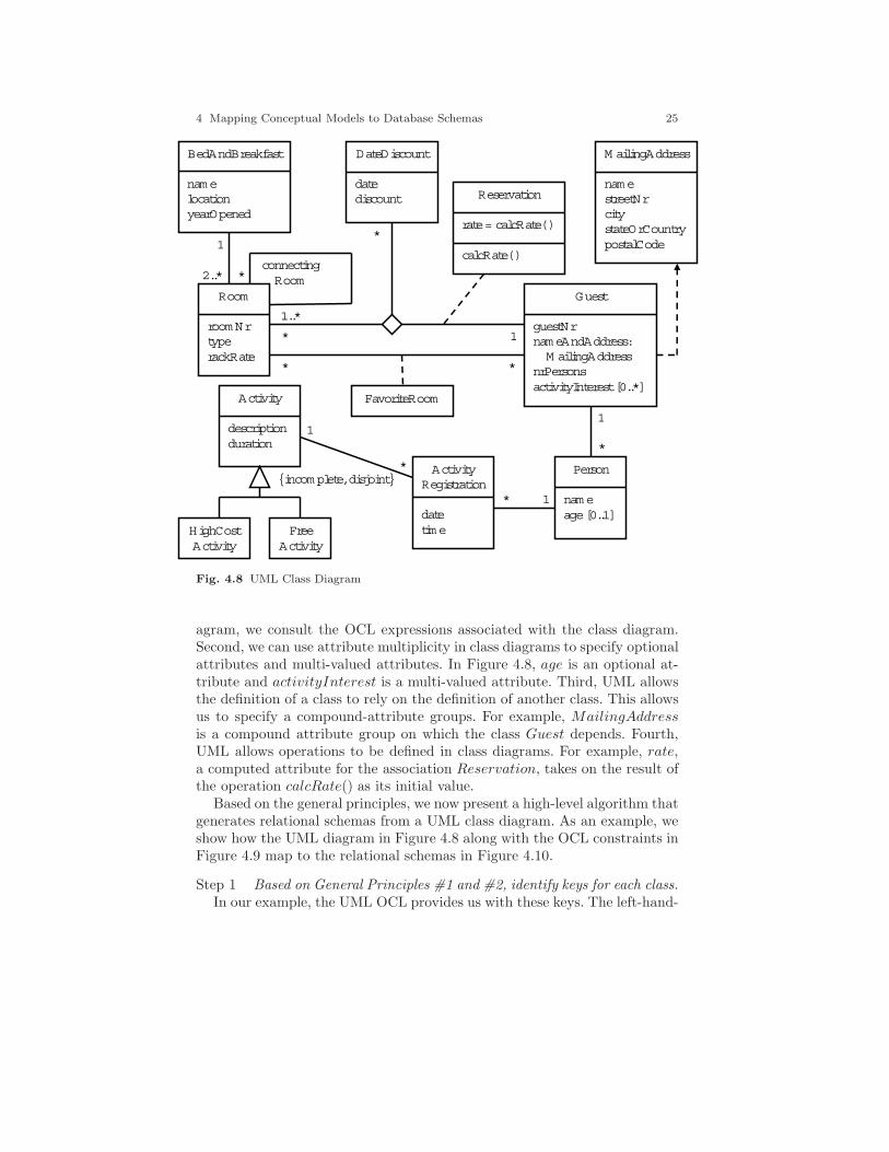
agram, we consult the OCL expressions associated with the class diagram.Second, we can use attribute multiplicity in class diagrams to specify optionalattributes and multi-valued attributes. In Figure 4.8, age is an optional at-tribute and activityInterest is a multi-valued attribute. Third, UML allowsthe definition of a class to rely on the definition of another class. This allowsus to specify a compound-attribute groups. For example, MailingAddressis a compound attribute group on which the class Guest depends. Fourth,UML allows operations to be defined in class diagrams. For example, rate,a computed attribute for the association Reservation, takes on the result ofthe operation calcRate() as its initial value.
Based on the general principles, we now present a high-level algorithm thatgenerates relational schemas from a UML class diagram. As an example, weshow how the UML diagram in Figure 4.8 along with the OCL constraints inFigure 4.9 map to the relational schemas in Figure 4.10.
Step 1 Based on General Principles #1 and #2, identify keys for each class.In our example, the UML OCL provides us with these keys. The left-hand-
26 David W. Embley and Wai Yin Mok
context BedAndBreakfastinv: BedAndBreakfast.allInstances()->forAll(b1, b2 |
b1.name = b2.name and b1.location = b2.location implies b1 = b2)-- name location → BedAndBreakfast
... -- roomNr name location → Room
... -- guestNr → Guest
... -- date → DateDiscount
... -- name guestNr → Person
... -- description → Activity
... -- name guestNr date time → ActivityRegistration
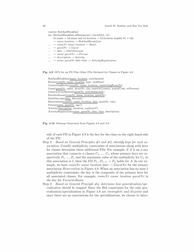
Fig. 4.9 OCL for an FD Plus Other FDs Declared for Classes in Figure 4.8.
BedAndBreakfast(name, location, yearOpened)
Room(roomNr, name, location, type, rackRate)
ConnectingRoom(roomNr, name, location, connectingRoomNr)
Guest(guestNr, name, streetNr, city, stateOrCountry, postalCode, nrPersons)
GuestActivityInterest(guestNr, activityInterest)
FavoriteRoom(roomNr, name, location, guestNr)
DateDiscount(date, discount)
Reservation(roomNr, name, location, date, guestNr, rate)
Person(name, guestNr, age?)
Activity(description, duration, costLevel?)
ActivityRegistration(name, guestNr, date, time, description)
Fig. 4.10 Schemas Generated from Figures 4.8 and 4.9.
side of each FD in Figure 4.9 is the key for the class on the right-hand-sideof the FD.
Step 2 Based on General Principles #1 and #2, identify keys for each as-sociation. Usually multiplicity constraints of associations along with keysfor classes determine these additional FDs. For example, if A is an n-aryassociation that connects n classes C1, ..., Cn whose primary keys are re-spectively P1, ..., Pn and the maximum value of the multiplicity for Cn inthis association is 1, then the FD P1...Pn−1 → Pn holds for A. In our ex-ample, we have roomNr name location date → GuestNr for the ternaryassociation Reservation in Figure 4.8. When an association has no max-1multiplicity constraints, the key is the composite of the primary keys forall associated classes. For example, roomNr name location guestNr isthe key for FavoriteRoom.
Step 3 Based on General Principle #4, determine how generalization/spe-cialization should be mapped. Since the ISA constraints for the only gen-eralization/specialization in Figure 4.8 are incomplete and disjoint andsince there are no associations for the specializations, we choose to intro-

4 Mapping Conceptual Models to Database Schemas 27
duce one new attribute, costLevel representing all specializations as ERMapping Rule #6.2b suggests.
Step 4 Based on General Principle #3, map classes to relational schemas.We generate a relational schema R for a class C as follows. R has thefollowing attributes:
• all the attributes of C except (1) those whose multiplicity is greaterthan one (e.g., activityInterest in Figure 4.8) and (2) those compoundattributes that reference another class (e.g., nameAndAddress in Fig-ure 4.8);
• all leaf attributes of compound attributes (e.g., name, streetNr, city,stateOrCountry, and postalCode are all included in the relationalschema for Guest);
• all attributes included in the primary key for C, if not already included(e.g., name and location from the class BedAndBreakfast are includedin the relational schema for Room); and
• for each association A, if a key of A is also a key of R, then (1) allattributes of A, if any, and (2) for each class C′ connected to C by A,the primary-key attributes of C′ (e.g., description, the primary key ofActivity, belongs in the relational schema for ActivityReservation).
Step 5 Based on General Principle #3, map remaining associations to re-lational schemas. An association remains after Step 4 only if it is notone-one and not one-many or many-one. We generate a relational schemaR for each remaining association A as follows. For each class C connectedby A, R includes the primary-key attributes of C. FavoriteRoom andReservation in Figure 4.10 are examples.
Step 6 Based on General Principle #3, map multi-valued attributes to re-lational schemas. For each multi-valued attribute M in a class C, generatea relational schema that includes M and the primary-key attributes ofC. The multi-valued attribute activityInterest in Guest in Figure 4.8 isan example, which yields the relational schema GuestActivityInterest inFigure 4.10.
Step 7 Based on General Principle #5, identify nullable attributes. In ourexample age is nullable because it is a single-valued, optional attribute ofGuest, and costLevel is nullable because the ISA hierarchy in Figure 4.8has an incomplete constraint.
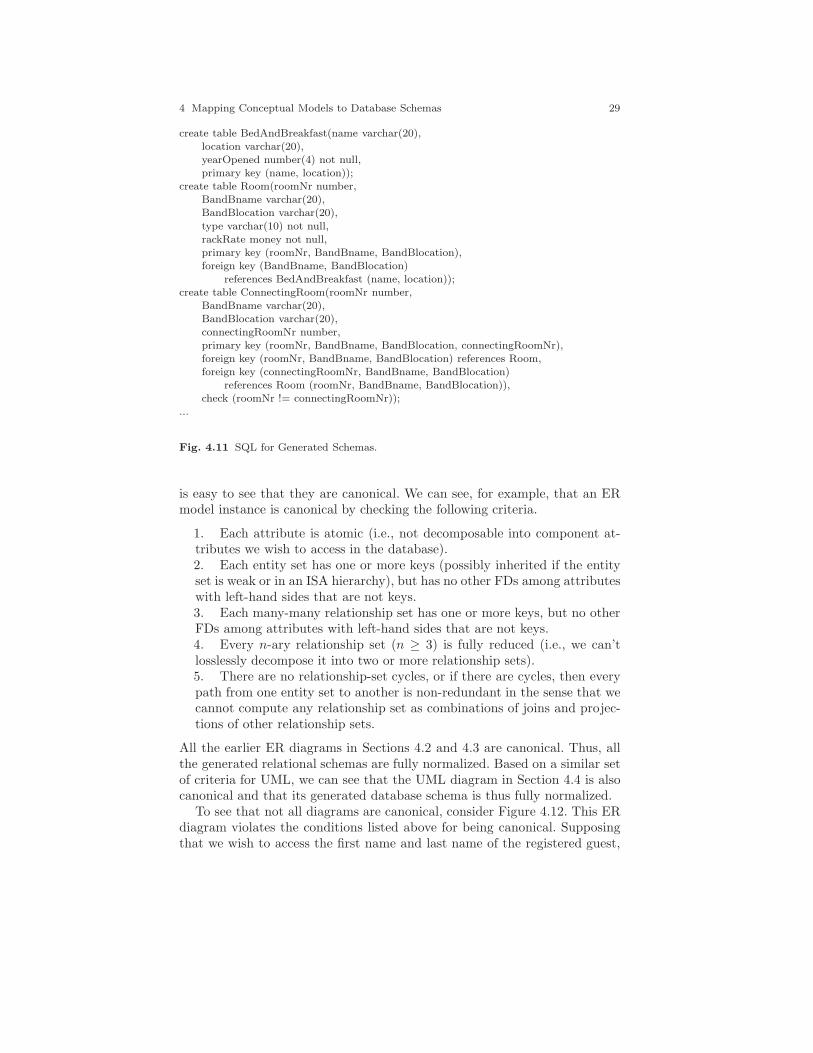
Once we have relational schemas for the database, like the ones in Fig-ure 4.10, we can derive SQL DDL for a relational database. We illustratehere5 how to turn generated relational schemas into SQL table creation state-ments. Figure 4.11 shows our SQL DDL for the first three relational schemasin Figure 4.10. The translation is straightforward.
5 We could have illustrated the derivation of SQL DDL for all earlier generated schemasas well as this one, but we only illustrate this derivation once.

28 David W. Embley and Wai Yin Mok
1. Obtain the name and basic attribute structure for the tables tobe created directly from the generated schemas. As Figure 4.11 shows,the BedAndBreakfast table has the attributes name, location, andyearOpened. We can rename attributes to make them more understand-able. BandBname and BandBlocation are preferable to name and locationin Room (otherwise most people would read name in Room as the nameof the room and location as the location of the room).2. Represent the constraints captured in the diagram and generatedschemas. The primary-key constraints come directly from the relationalschemas, as do other uniqueness constraints. The foreign-key constraintscome indirectly from the relational schemas. An attribute or attributegroup that is not a key in a relational schema R but is a key in a rela-tional schema S is a foreign key for R that references S. BandBname andBandBlocation, for example, constitute a composite foreign key in Roomthat references the composite key name and location in BedAndBreakfast.As may be desirable, we also add check constraints, such as roomNr !=connectingRoomNr. These constraints, however, are not derivable fromthe relational schemas we generate.3. Add type declarations, which are usually only implicit in the conceptual-model instance. The types varchar, number, and money are examples.4. Reflect the null properties of the relational schemas in the SQL DDL.Primary-key attributes are not null by default. All other attributes arenullable unless otherwise specified by a not null constraint.
4.5 Normal Form Guarantees
When mapping conceptual models to database schemas, the question of nor-malization naturally arises. Are generated relational schemas fully normal-ized? By “fully normalized,” we mean they are in PJNF— Project-Join Nor-mal Form— which also implies that they are in 4NF, BCNF, 3NF, 2NF, and1NF. Interestingly, we can answer “yes” for conceptual-model diagrams thatare canonical.
Although circular, the easiest way to define canonical is that when mappedaccording to the mapping rules or algorithms, every relational schema is fullynormalized. In practice, many (if not most) diagrams are canonical.6 Givinga general statement that characterizes canonical for all types of conceptualmodels (or even for one type of conceptual model) is difficult especially if thecharacterization is to be given in the least constraining way. Many conceptualmodel instances, however, satisfy stronger than necessary conditions, and it
6 Many argue that if conceptual-model diagrams are not canonical, they are not goodquality diagrams.
4 Mapping Conceptual Models to Database Schemas 29
create table BedAndBreakfast(name varchar(20),location varchar(20),yearOpened number(4) not null,primary key (name, location));
create table Room(roomNr number,BandBname varchar(20),BandBlocation varchar(20),
type varchar(10) not null,rackRate money not null,primary key (roomNr, BandBname, BandBlocation),foreign key (BandBname, BandBlocation)
references BedAndBreakfast (name, location));create table ConnectingRoom(roomNr number,
BandBname varchar(20),BandBlocation varchar(20),connectingRoomNr number,primary key (roomNr, BandBname, BandBlocation, connectingRoomNr),foreign key (roomNr, BandBname, BandBlocation) references Room,foreign key (connectingRoomNr, BandBname, BandBlocation)
references Room (roomNr, BandBname, BandBlocation)),check (roomNr != connectingRoomNr));
...
Fig. 4.11 SQL for Generated Schemas.
is easy to see that they are canonical. We can see, for example, that an ERmodel instance is canonical by checking the following criteria.
1. Each attribute is atomic (i.e., not decomposable into component at-tributes we wish to access in the database).2. Each entity set has one or more keys (possibly inherited if the entityset is weak or in an ISA hierarchy), but has no other FDs among attributeswith left-hand sides that are not keys.3. Each many-many relationship set has one or more keys, but no otherFDs among attributes with left-hand sides that are not keys.4. Every n-ary relationship set (n ≥ 3) is fully reduced (i.e., we can’tlosslessly decompose it into two or more relationship sets).5. There are no relationship-set cycles, or if there are cycles, then everypath from one entity set to another is non-redundant in the sense that wecannot compute any relationship set as combinations of joins and projec-tions of other relationship sets.
All the earlier ER diagrams in Sections 4.2 and 4.3 are canonical. Thus, allthe generated relational schemas are fully normalized. Based on a similar setof criteria for UML, we can see that the UML diagram in Section 4.4 is alsocanonical and that its generated database schema is thus fully normalized.
To see that not all diagrams are canonical, consider Figure 4.12. This ERdiagram violates the conditions listed above for being canonical. Supposingthat we wish to access the first name and last name of the registered guest,

30 David W. Embley and Wai Yin Mok
Type RackRate RoomNr Date GuestNr Rate Discount Date Discount Rate = (1 – Discount/100)RackRate Includes = Package,Description(Has || IsSignedUpFor) IsSignedUpFor = GuestNr,Description(Has || Includes) HasReservationFor = ||(Package GuestNr, GuestNr Description, RoomNr Date GuestNr Discount Rate)
includes
has
Room
RoomNr
Rate
has reservation
for Guest
is signed up
for
Activity
Nam e
Description
Duration
Date
NrInParty
Type
Rack Rate
Discount
PackageDeal
GuestNr
Package
Fig. 4.12 ER Diagram with Constraints whose Standard Mapping will Yield NormalForm Violations.
Name is not atomic and thus is an example of a violation of Condition #1.The diagram violates Condition #2 because of the FD Type → RackRate,whose left-hand side is not a key for Room. The diagram violates Condition#3 because the left-hand side of the FD Date → Discount is not a key forthe relationship set has reservation for. (We are assuming for this examplethat the discount amount depends on the date — i.e., whether it is a weekend,weekday, holiday, during the off season, etc.) The diagram violates Condition#4 because we can losslessly decompose has reservation for into three rela-tionship sets: one between Package Deal and Guest (which also happens tobe equivalent to the has relationship set), one between Guest and Activity(which also happens to be equivalent to the is signed up for relationshipset), and one between Room and Guest. (Perhaps this original quaternaryrelationship set in Figure 4.12 arose because a designer was told that whenguests make reservations they always also sign up for a package deal whichincludes certain activities.) The diagram violates Condition #5 because ofthe cycle through the relationship sets has, includes, and is signed up for,in which includes and is signed up for are computable from the other tworelationship sets in the cycle.
As we shall see in Section 4.5.1, if we use standard schema generationprocedures, we would generate relational schemas that are not normalized.

4 Mapping Conceptual Models to Database Schemas 31
We should then normalize them using standard normalization techniques dis-cussed in Chapter 6. We will also see in Section 4.5.2, however, that we canrearrange the diagram so that it has the same semantics but is canonical. Ifwe then use standard schema generation procedures, the resulting relationalschemas will be fully normalized. We will thus see that there are two ap-proaches to ensure that generated relational schemas are fully normalized. (1)We can first generate relational schemas and then normalize using standardnormalization techniques. (2) We can first canonicalize a conceptual-modeldiagram and then generate relational schemas.
4.5.1 Map—Then Normalize
Room(RoomNr, Type, RackRate)
Guest(GuestNr, Name, NrInParty, Package)
Activity(Description, Duration)
HasReservationFor(RoomNr, Date, GuestNr, Rate, Discount, Package, Description)
IsSignedUpFor(GuestNr, Description)
Includes(Package, Description)
Fig. 4.13 Generated Relational Schemas —Not Normalized.
Figure 4.13 shows the relational schemas we would generate accordingto the standard ER mapping rules in Sections 4.2 and 4.3. We must nowrecognize the normal-form violations and fix them.
• Guest is not in 1NF because Name is not atomic. We replace Nameby FirstName and LastName in Guest, which yields Guest(GuestNr,F irstName, LastName, NrInParty, Package).
• HasReservationFor is not in 2NF because of Date →Discount. We decompose HasReservationFor, which yieldsHasReservationFor(RoomNr, Date, GuestNr, Rate, Package,Description) and a new relational schema DateDiscount(Date,Discount).
• Room is not in 3NF because of Type → RackRate. We decomposeRoom, which yields Room(RoomNr, Type) and a new relational schemaRoomType(Type, RackRate).
• The relationship set HasReservationFor is not in 4NF/PJNF because ofthe join dependency �(Package GuestNr, GuestNr Description, RoomNrDate GuestNr Rate). (Note that Discount is missing because we have al-ready decomposed HasReservationFor in a step above.) We thus decom-pose HasReservationFor according to the join dependency, which yieldsthree relational schemas: HasReservationFor(RoomNr, Date, GuestNr,
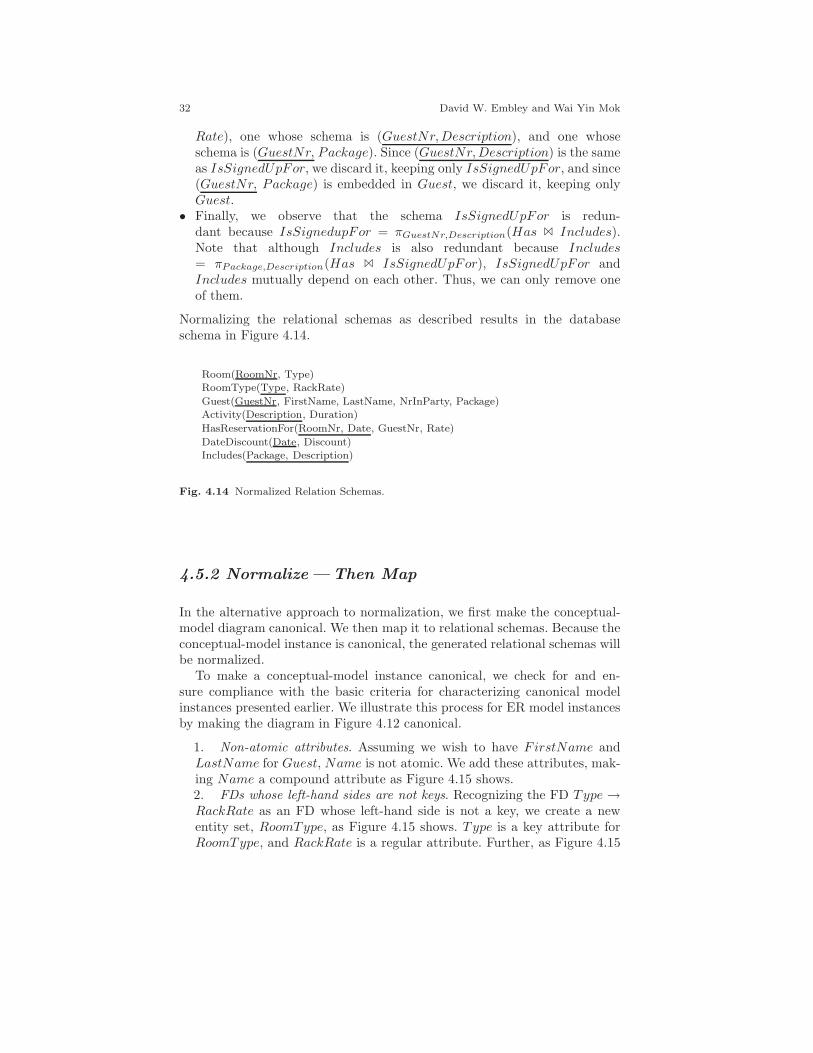
32 David W. Embley and Wai Yin Mok
Rate), one whose schema is (GuestNr, Description), and one whoseschema is (GuestNr, Package). Since (GuestNr, Description) is the sameas IsSignedUpFor, we discard it, keeping only IsSignedUpFor, and since(GuestNr, Package) is embedded in Guest, we discard it, keeping onlyGuest.
• Finally, we observe that the schema IsSignedUpFor is redun-dant because IsSignedupFor = πGuestNr,Description(Has � Includes).Note that although Includes is also redundant because Includes= πPackage,Description(Has � IsSignedUpFor), IsSignedUpFor andIncludes mutually depend on each other. Thus, we can only remove oneof them.
Normalizing the relational schemas as described results in the databaseschema in Figure 4.14.
Room(RoomNr, Type)RoomType(Type, RackRate)
Guest(GuestNr, FirstName, LastName, NrInParty, Package)Activity(Description, Duration)
HasReservationFor(RoomNr, Date, GuestNr, Rate)
DateDiscount(Date, Discount)Includes(Package, Description)
Fig. 4.14 Normalized Relation Schemas.
4.5.2 Normalize—Then Map
In the alternative approach to normalization, we first make the conceptual-model diagram canonical. We then map it to relational schemas. Because theconceptual-model instance is canonical, the generated relational schemas willbe normalized.
To make a conceptual-model instance canonical, we check for and en-sure compliance with the basic criteria for characterizing canonical modelinstances presented earlier. We illustrate this process for ER model instancesby making the diagram in Figure 4.12 canonical.
1. Non-atomic attributes. Assuming we wish to have FirstName andLastName for Guest, Name is not atomic. We add these attributes, mak-ing Name a compound attribute as Figure 4.15 shows.2. FDs whose left-hand sides are not keys. Recognizing the FD Type →RackRate as an FD whose left-hand side is not a key, we create a newentity set, RoomType, as Figure 4.15 shows. Type is a key attribute forRoomType, and RackRate is a regular attribute. Further, as Figure 4.15
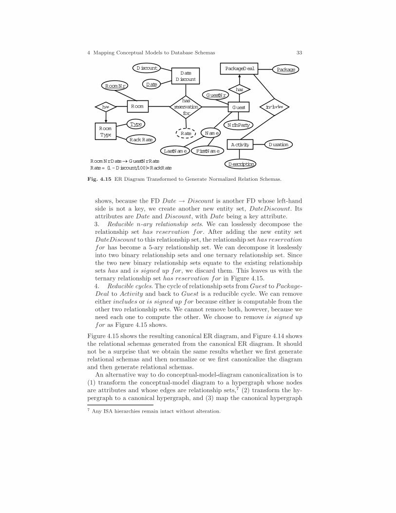
4 Mapping Conceptual Models to Database Schemas 33
Room Nr Date GuestNr Rate Rate = (1 – Discount/100)RackRate
includes
has
Room
Room Nr
Rate
has reservation
for Guest
Activity
Name
Description
Duration
Date
NrInParty
Rack Rate
Discount PackageDeal
GuestNr
Package
has
Room Type
Type
Date Discount
LastName FirstName
Fig. 4.15 ER Diagram Transformed to Generate Normalized Relation Schemas.
shows, because the FD Date → Discount is another FD whose left-handside is not a key, we create another new entity set, DateDiscount. Itsattributes are Date and Discount, with Date being a key attribute.3. Reducible n-ary relationship sets. We can losslessly decompose therelationship set has reservation for. After adding the new entity setDateDiscount to this relationship set, the relationship set has reservationfor has become a 5-ary relationship set. We can decompose it losslesslyinto two binary relationship sets and one ternary relationship set. Sincethe two new binary relationship sets equate to the existing relationshipsets has and is signed up for, we discard them. This leaves us with theternary relationship set has reservation for in Figure 4.15.4. Reducible cycles. The cycle of relationship sets from Guest to Package-Deal to Activity and back to Guest is a reducible cycle. We can removeeither includes or is signed up for because either is computable from theother two relationship sets. We cannot remove both, however, because weneed each one to compute the other. We choose to remove is signed upfor as Figure 4.15 shows.
Figure 4.15 shows the resulting canonical ER diagram, and Figure 4.14 showsthe relational schemas generated from the canonical ER diagram. It shouldnot be a surprise that we obtain the same results whether we first generaterelational schemas and then normalize or we first canonicalize the diagramand then generate relational schemas.
An alternative way to do conceptual-model-diagram canonicalization is to(1) transform the conceptual-model diagram to a hypergraph whose nodesare attributes and whose edges are relationship sets,7 (2) transform the hy-pergraph to a canonical hypergraph, and (3) map the canonical hypergraph
7 Any ISA hierarchies remain intact without alteration.
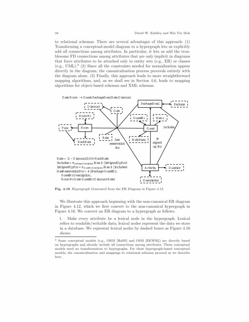
34 David W. Embley and Wai Yin Mok
to relational schemas. There are several advantages of this approach: (1)Transforming a conceptual-model diagram to a hypergraph lets us explicitlyadd all connections among attributes. In particular, it lets us add the trou-blesome FD connections among attributes that are only implicit in diagramsthat force attributes to be attached only to entity sets (e.g., ER) or classes(e.g., UML).2 (2) Since all the constraints needed for normalization appeardirectly in the diagram, the canonicalization process proceeds entirely withthe diagram alone. (3) Finally, this approach leads to more straightforwardmapping algorithms, and, as we shall see in Section 4.6, leads to mappingalgorithms for object-based schemas and XML schemas.
has reservation
for
is signed up for
includes
Package
NrInParty
Duration
Rate = (1 – Discount/100)RackRate Includes = Package,Description(Has || IsSignedUpFor) IsSignedUpFor = GuestNr,Description(Has || Includes) HasReservationFor = ||(Package GuestNr, GuestNr Description, RoomNr Date GuestNr Discount Rate)
Room
RoomNr
Rate
Guest
Activity
Name
Description
Date
Type
RackRate
DiscountPackageDeal
GuestNr
Date Room Guest PackageDeal Rate Discount
Fig. 4.16 Hypergraph Generated from the ER Diagram in Figure 4.12.
We illustrate this approach beginning with the non-canonical ER diagramin Figure 4.12, which we first convert to the non-canonical hypergraph inFigure 4.16. We convert an ER diagram to a hypergraph as follows.
1. Make every attribute be a lexical node in the hypergraph. Lexicalrefers to readable/writable data; lexical nodes represent the data we storein a database. We represent lexical nodes by dashed boxes as Figure 4.16shows.
2 Some conceptual models (e.g., ORM [Hal95] and OSM [EKW92]) are directly basedon hypergraphs and already include all connections among attributes. These conceptualmodels need no transformation to hypergraphs. For these hypergraph-based conceptualmodels, the canonicalization and mappings to relational schemas proceed as we describehere.
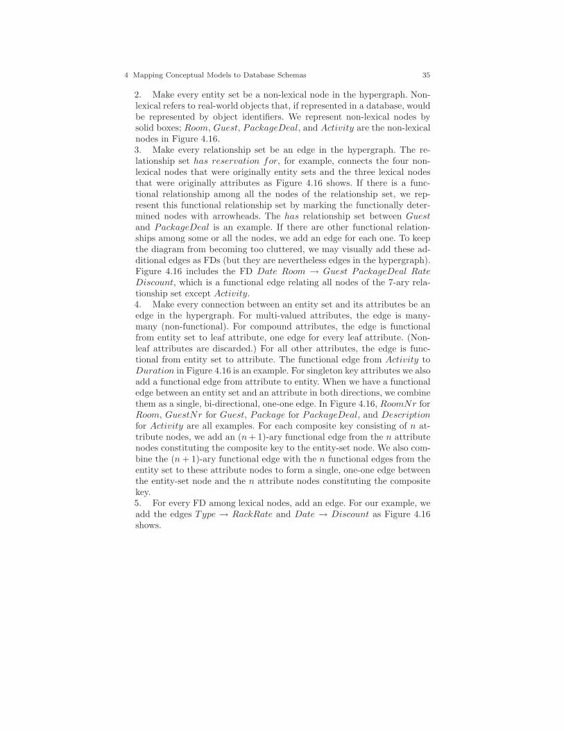
4 Mapping Conceptual Models to Database Schemas 35
2. Make every entity set be a non-lexical node in the hypergraph. Non-lexical refers to real-world objects that, if represented in a database, wouldbe represented by object identifiers. We represent non-lexical nodes bysolid boxes; Room, Guest, PackageDeal, and Activity are the non-lexicalnodes in Figure 4.16.3. Make every relationship set be an edge in the hypergraph. The re-lationship set has reservation for, for example, connects the four non-lexical nodes that were originally entity sets and the three lexical nodesthat were originally attributes as Figure 4.16 shows. If there is a func-tional relationship among all the nodes of the relationship set, we rep-resent this functional relationship set by marking the functionally deter-mined nodes with arrowheads. The has relationship set between Guestand PackageDeal is an example. If there are other functional relation-ships among some or all the nodes, we add an edge for each one. To keepthe diagram from becoming too cluttered, we may visually add these ad-ditional edges as FDs (but they are nevertheless edges in the hypergraph).Figure 4.16 includes the FD Date Room → Guest PackageDeal RateDiscount, which is a functional edge relating all nodes of the 7-ary rela-tionship set except Activity.4. Make every connection between an entity set and its attributes be anedge in the hypergraph. For multi-valued attributes, the edge is many-many (non-functional). For compound attributes, the edge is functionalfrom entity set to leaf attribute, one edge for every leaf attribute. (Non-leaf attributes are discarded.) For all other attributes, the edge is func-tional from entity set to attribute. The functional edge from Activity toDuration in Figure 4.16 is an example. For singleton key attributes we alsoadd a functional edge from attribute to entity. When we have a functionaledge between an entity set and an attribute in both directions, we combinethem as a single, bi-directional, one-one edge. In Figure 4.16, RoomNr forRoom, GuestNr for Guest, Package for PackageDeal, and Descriptionfor Activity are all examples. For each composite key consisting of n at-tribute nodes, we add an (n + 1)-ary functional edge from the n attributenodes constituting the composite key to the entity-set node. We also com-bine the (n + 1)-ary functional edge with the n functional edges from theentity set to these attribute nodes to form a single, one-one edge betweenthe entity-set node and the n attribute nodes constituting the compositekey.5. For every FD among lexical nodes, add an edge. For our example, weadd the edges Type → RackRate and Date → Discount as Figure 4.16shows.

36 David W. Embley and Wai Yin Mok
We next make a non-canonical hypergraph canonical in three main steps.8
We illustrate these steps by converting the non-canonical hypergraph in Fig-ure 4.16 to the canonical hypergraph in Figure 4.17.
1. Decompose all hyperedges that can be losslessly decomposed. In Fig-ure 4.16 we decompose the 7-ary edge along with the edge represented bythe FD to a 4-ary functional edge Room Date → Guest Rate plus severalother edges, all of which eventually turn out to be redundant. Figure 4.17shows this 4-ary edge, but none of the redundant edges.2. Remove all redundant edges and all redundant hyperedge components.In addition to the redundant edges just generated and ignored, we alsoremove the Room-RackRate edge and the Guest-Activity edge.3. Merge each non-lexical node with its key (any one key, if there ismore than one choice). For example, we merge Room with its primary keyRoomNr, which, as Figure 4.16 shows, are in a one-one correspondence.The result of this merge is the lexical node RoomNr, which has beenmerged with Room as Figure 4.17 shows. Similarly, we merge Packagewith PackageDeal, GuestNr with Guest, and Description with Activity.
room type
has reservation
for includes NrInParty
Duration Rate = (1 – Discount/100)RackRate
RoomNr
Rate
GuestNr
Description
Nam e Date
Type
RackRate
Discount
Package
Fig. 4.17 Canonical Hypergraph.
8 Usually these three main steps are enough. Exceptions arise (1) when the hypergraph iscyclic after redundancies have been removed and (2) when optional participation interfereswith our ability to capture all element values. An example of the first would be an additionaledge between Description and Duration where one means the average duration for anactivity and the other means the maximum allowable duration. In this case, we need toqualify Duration to be, say, AveDuration and MaxDuration, and generate the relationalschema for Activity with three attributes, Duration, AveDuration, and MaxDuration.An example of the second would be optional participation for Name where we might wantto keep all names of guests even if they have no guest number. In this case, we need aseparate table for Name alone since we cannot capture all names in the Guest relationalschema, which demands a GuestNr for every Guest. We can resolve both of these issuesby adding roles. See [Emb98] for details.

4 Mapping Conceptual Models to Database Schemas 37
Once we have a canonical hypergraph, the conversion to a relationaldatabase schema is straightforward. With one mapping rule, we can obtaina set of normalized relational schemas:
Every edge becomes a relational schema. If the edge is functional inonly one direction, the tail attribute(s) constitute the key. If the edge isfunctional in both directions (from tail(s) to head(s) and from head(s)to tail(s)), the head attribute(s) constitute a key as well as the tail at-tribute(s). If the edge is not functional, all the connected attributes con-stitute the key.
For example, RoomNr → Type is a functional edge whose generated rela-tional schema is (RoomNr, Type), and RoomNr Date → GuestNr Rate isanother functional edge whose generated relational schema is (RoomNr, Date,GuestNr, Rate). The edge between Package and Description is a non-functional, and thus its generated relational schema is (Package, Description).We have no edge that is functional in both directions. To illustrate a bidi-rectional edge, suppose, as in Figure 4.1, that in addition to room numbers,rooms in a bed and breakfast establishment also have identifying names. Wewould then have another attribute RoomName in a one-to-one correspon-dence with RoomNr. In this case, we would generate the relational schema(RoomNr, RoomName) in which both RoomNr is a key and RoomNameis a key.
Although this single rule generates relational schemas that are all normal-ized, it fragments the database into more relational schemas than necessary.Thus, to finalize the relational schemas for the database, we merge as manyas we can without violating any normal form using the following simple rule:
Merge schemas that have a common key.
For example, we would merge (GuestNr, Name), (GuestNr, Package), and(GuestNr, NrInParty), because they all have the key GuestNr. We also adda name as we merge so that we have a standard relational schema. We wouldthus obtain Guest(GuestNr, Name, Package, NrInParty). Note that wewould not merge (RoomNr, Type) and (RoomNr, Date, GuestNr, Rate) be-cause they do not have a common key— RoomNr is not the same as the com-posite key RoomNr Date. Forming the relational schemas from Figure 4.17and then merging those that have a common key results in the relationalschemas in Figure 4.14, except that Name appears in place of FirstNameand LastName since we started with Name rather than FirstName andLastName in Figure 4.12.
Note that we have said nothing about ISA hierarchies. This is becausethere is no change to the way we map ISA hierarchies to relational schemas.There is a change, however, when we convert non-canonical hypergraphs tocanonical hypergraphs. When we merge a non-lexical node with its key, wepropagate this merge all the way down the hierarchy. Thus, for example,when we convert the ER diagram in Figure 4.5 to a canonical hypergraph,

38 David W. Embley and Wai Yin Mok
every node in the ISA hierarchy rooted at Guest becomes a lexical node withthe name GuestNr.9 If we choose to have a relational schema for every nodein the ISA hierarchy, we simply do not merge relational schemas in the ISAhierarchy that share a common key. If we choose to have a relational schemaonly for the root of the ISA hierarchy, we merge in the usual way. If we chooseto have relational schemas only for the leaves of the ISA hierarchy, we mergealong every path from the root to each of the leaves.
4.6 Mappings for Object-Based and XML Databases
In this section, we show how to generate generic hierarchical structures,called scheme trees, from a canonical hypergraph. Since scheme trees aregeneric hierarchical structures, it is straightforward to map scheme trees todatabase schemas that support hierarchical data. As an example, we showhow to map scheme trees to object-relational database schema instances andXML schema instances. Since object-oriented databases are similar to object-relational databases, our example for object-relational databases serves forobject-oriented databases as well.
The central idea of generating scheme trees is to ensure that each instanceof a hyperedge in a canonical hypergraph only appears once in a scheme-tree instance. To do so, our scheme trees observe the many-one and one-oneconstraints in the hypergraph. We capture the essence of the idea in thefollowing algorithm.2
While there is an unmarked hyperedge, do:Select a subset V of vertices in an unmarked hyperedge E
to be the root node of a new scheme tree T .While we can add an unmarked hyperedge E to T , do:
(We can add an unmarked edge E if the followingconditions hold: E must have a nonempty intersection Sof vertices with T . A node N must exist in T such thatthe set S is contained in the union of the nodes above orequal to N and S functionally determines the union ofthe nodes above or equal to N .)
Add E to T as follows:If S functionally determines E − S
Add the vertices in E − S to the node N .Else
9 To keep the various nodes straight, we should add comments to the diagram. Exceptthat these comments help us keep the nodes conceptually straight and may help us choosenames for relational schemas, we can ignore these comments.2 The algorithm is a simplified version of the heuristic n-ary algorithm in [ME06], which
generates scheme trees from a canonical hypergraph.

4 Mapping Conceptual Models to Database Schemas 39
Make a node consisting of the vertices in E − S andadd it to the tree as a child node of N .
Mark E as used.
If we select Package (a subset of the vertices in the edge GuestNr →Package) as the root node, this algorithm generates the scheme tree in Fig-ure 4.18a. Having selected {Package} as the root for T and E = {Package,GuestNr} as the edge we are considering, we see that all conditions of thewhile loop trivially hold (as they always do for the initial selection of a rootand an edge). Since S = {Package} does not functionally determine E − S= {GuestNr} (it is actually the other way around), we add {GuestNr} asa child node of the node {Package}. Continuing, we next consider the edgeGuestNr → Name. Here, the conditions of the while loop also hold with S= {GuestNr}, N = {GuestNr}, and GuestNr → GuestNr Package. SinceS functionally determines E − S = {GuestNr, Name} − {GuestNr} ={Name}, we add Name to the node containing GuestNr. Similarly, we addNrInParty to this node, thus completing the second node in Figure 4.18a.We next consider the edge RoomNr Date → GuestNr Rate. The intersectionS with T is {GuestNr}, which is contained in the node N we just created.Further, GuestNr → GuestNr Name NrInParty Package so that it func-tionally determines the union of N and the node above N (the root). SinceS does not functionally determine E−S (i.e., {GuestNr} does not function-ally determine {RoomNr, Date, Rate}), we make a new node consisting of{RoomNr, Date, Rate} and place it below N as Figure 4.18a shows. Con-tinuing, we next consider the nonfunctional edge {Package, Description}.The nonempty intersection S with the scheme tree T we have built so far is{Package}. Since {Description} does not functionally determine {Package},we form a new node consisting only of {Description} and add it as anotherchild node of {Package}, resulting in the scheme tree T in Figure 4.18a. Ofthe remaining four edges, Type → RackRate has an empty intersection withT , and the rest (Date → Discount, RoomNr → Type, and Description →Duration) do not satisfy the functional-dependency condition of the whileloop for the scheme tree in Figure 4.18a.
Figure 4.18b shows the textual representation for the scheme tree in Fig-ure 4.18a. In the textual representation, each node appears within paren-theses with a star to indicate repetition; parenthesized nodes appear in lineaccording to their nested position in the scheme tree.
Choosing the best starting place to run the algorithm depends on the se-mantics of the application. In our example, starting with Package is probablynot best. The main point of the application is to rent rooms to guests, notabout the activity packages they may choose. Thus, most of the processingis likely to be about looking up guests. Hence, a likely better starting placefor our scheme-tree algorithm is to choose GuestNr as the root. When westart with GuestNr as the root of the first tree and run the algorithm re-peatedly until all edges are in some scheme tree, we obtain the scheme treesin Figure 4.19.
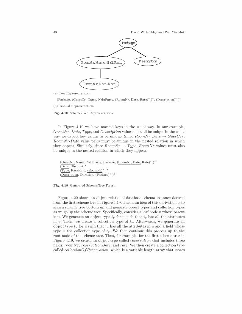
40 David W. Embley and Wai Yin Mok
Package
GuestNr, Nam e, NrInParty Description
RoomNr, Date, Rate
(a) Tree Representation.
(Package, (GuestNr, Name, NrInParty, (RoomNr, Date, Rate)* )*, (Description)* )*
(b) Textual Representation.
Fig. 4.18 Scheme-Tree Representations.
In Figure 4.19 we have marked keys in the usual way. In our example,GuestNr, Date, Type, and Description values must all be unique in the usualway we expect key values to be unique. Since RoomNr Date → GuestNr,RoomNr-Date value pairs must be unique in the nested relation in whichthey appear. Similarly, since RoomNr → Type, RoomNr values must alsobe unique in the nested relation in which they appear.
(GuestNr, Name, NrInParty, Package, (RoomNr, Date, Rate)* )*
(Date, Discount)*
(Type, RackRate, (RoomNr)* )*
(Description, Duration, (Package)* )*
Fig. 4.19 Generated Scheme-Tree Forest.
Figure 4.20 shows an object-relational database schema instance derivedfrom the first scheme tree in Figure 4.19. The main idea of this derivation is toscan a scheme tree bottom up and generate object types and collection typesas we go up the scheme tree. Specifically, consider a leaf node v whose parentis u. We generate an object type tv for v such that tv has all the attributesin v. Then, we create a collection type of tv. Afterwards, we generate anobject type tu for u such that tu has all the attributes in u and a field whosetype is the collection type of tv. We then continue this process up to theroot node of the scheme tree. Thus, for example, for the first scheme tree inFigure 4.19, we create an object type called reservation that includes threefields: roomNr, reservationDate, and rate. We then create a collection typecalled collectionOfReservation, which is a variable length array that stores

4 Mapping Conceptual Models to Database Schemas 41
reservation objects. Finally, we create an object type called guest for theroot node. Note that there is a field called reservations in guest whose type iscollectionOfReservation. To store guest objects, we create tableOfGuest—a table of this type. Unfortunately, declared key constraints are not typicallyprovided by object-relational databases. Thus, as for any constraint we wishto enforce that is not directly supported by the database, we must provideour own code to check and enforce it.
create type reservation as object (roomNr integer,reservationDate date,rate number,static function createReservation(roomNo integer, resDate date, rate number)
return reservation,static function createReservation(roomNo integer, resDate date) return reservation);
create type body reservation isstatic function createReservation(roomNo integer, resDate date, rate number)
return reservation isbegin
return reservation(roomNo, resDate, rate);end;
static function createReservation(roomNo integer, resDate date) return reservation isbegin
return reservation(roomNo, resDate,(1-discount.getDiscountRate(resDate)/100)* roomType.getRackRate(roomNo));
end;end;create type collectionOfReservation as
varray(200) of reservation;create type guest as object (
guestNr integer,name varchar2(30),nrInParty integer,package varchar2(40),reservations collectionOfReservation);
create table tableOfGuest of guest;
Fig. 4.20 Derived Object-Relational Database Schema Instance.
Figure 4.21 shows the first and last parts of a derived XML schema in-stance for the generated scheme-tree forest in Figure 4.19. Several deriva-tions are possible; Figure 4.21 shows one derived as follows. For each nestingof a scheme tree we provide two names— one for describing the group andone describing an individual in the group. Thus, for the scheme tree (Type,RackRate, (RoomNr)* )* we introduce the name RoomTypes for the group,RoomType for the individuals in the group, Rooms for the nested group,and Room for the individuals in the nested group. We nest these names ap-
42 David W. Embley and Wai Yin Mok
propriately as Figure 4.21 shows. We then put the attributes in their properplace— we nest Type and RackRate under RoomType and RoomNr un-der Room. The type for Type is xs:ID making it unique throughout thedocument. Since Type appears nowhere else in the scheme-tree forest in Fig-ure 4.19, this simple declaration is sufficient. For RoomNr, which does ap-pear in one other scheme tree, we scope the extent of uniqueness to be withinRoomTypes and make a key declaration as Figure 4.21 shows. Further, whenan attribute appears in more than one scheme tree, we use ref to referencea single declaration for its type. RoomNr is an example; its type declarationalong with the type declarations for Date and Package which also appear inmore than one scheme tree appear globally at the end of the XML schemainstance in Figure 4.21. In the first part of the XML schema instance inFigure 4.21, we have declarations for the roots of each of the scheme trees,Guests, Activities, DateDiscounts, and RoomTypes all under the ultimateroot, Document. We allow each of them to be optional except RoomTypes.(Although there may be no guests, activities, or date-discounts, if there areno rooms, there is no bed and breakfast establishment.)
4.7 Additional Readings
From the beginning, mappings from conceptual-model instances to databaseschemas have been an important part of the conceptual-modeling literature.Peter Chen’s seminal article on the ER model includes an extensive discussionof mapping the ER model to various database models [Che76]. Ever since theappearance of this seminal article, discussions of mapping conceptual-modelinstances to database schemas have continued. Notable, along the way, arean ACM Computing Surveys article [TYF86] and a foundational book onconceptual database design [BCN92]. Most current database text books (e.g.,[UW02, EN04, SKS06]) contain chapters on mapping conceptual models todatabase schemas.
Normalization concerns have also always been a part of mapping conceptual-model instances to database schemas. Chen’s seminal article [Che76] ad-dressed normalization, and his mappings did yield relations in 3NF underhis assumptions. Along the way other researchers have added insights aboutnormalization. Researchers have suggested both the map-then-normalize ap-proach [TYF86] and the normalize-then-map approach [CNC81, Lin85]. In[BCN92] the authors take the point of view that ER diagrams are not of goodquality unless they are canonical, and they talk about canonicalizing ER di-agrams as one way to help create high-quality diagrams. The hypergraphapproach to normalization appeared initially in [EL89]; full details appearedlater in [Emb98].
Only recently have articles appeared that describe the process of mappingconceptual models for object-based, object-oriented, and XML databases.

4 Mapping Conceptual Models to Database Schemas 43
<?xml version=”1.0” encoding=”UTF-8”?><xs:schema xmlns:xs=”http://www.w3.org/2001/XMLSchema” elementFormDefault=”qualified”>
<xs:element name=”Document”><xs:complexType>
<xs:sequence><xs:element ref=”Guests” minOccurs=”0”/><xs:element ref=”Activities” minOccurs=”0”/>
<xs:element ref=”DateDiscounts” minOccurs=”0”/><xs:element ref=”RoomTypes”/>
</xs:sequence></xs:complexType>
</xs:element>...
<xs:element name=”RoomTypes”><xs:complexType>
<xs:sequence><xs:element name=”RoomType” maxOccurs=”unbounded”>
<xs:complexType><xs:sequence>
<xs:element name=”Rooms”><xs:complexType>
<xs:sequence><xs:element name=”Room” maxOccurs=”unbounded”>
<xs:complexType><xs:attribute ref=”RoomNr”/>
</xs:complexType></xs:element>
</xs:sequence></xs:complexType>
</xs:element></xs:sequence><xs:attribute name=”Type” type=”xs:ID”/><xs:attribute name=”RackRate” type=”xs:double”/>
</xs:complexType></xs:element>
</xs:sequence></xs:complexType><xs:key name=”RoomNrKey”>
<xs:selector xpath=”./RoomType/Rooms/Room”/><xs:field xpath=”@RoomNr”/>
</xs:key></xs:element><xs:attribute name=”RoomNr” type=”xs:integer”/><xs:attribute name=”Date” type=”xs:date”/><xs:attribute name=”Package” type=”xs:string”/>
</xs:schema>
Fig. 4.21 Derived XML Schema Instance.

44 David W. Embley and Wai Yin Mok
Some initial thoughts appeared in [Emb98, EM01]. Proofs that generatedscheme trees have no redundancy appeared later [ME06].
References
[BCN92] C. Batini, S. Ceri, and S.B. Navathe. Conceptual Database Design: An Entity-Relationship Approach. The Benjamin/Cummings Publishing Company, Inc.,Redwood City, California, 1992.
[Che76] P.P. Chen. The entity-relationship model—toward a unified view of data. ACMTransactions on Database Systems, 1(1):9–36, March 1976.
[CNC81] I. Chung, F. Nakamura, and P.P. Chen. A decomposition of relations using theentity-relationship approach. In Proceedings of the 2nd International Confer-ence on Entity-Relationship Approach to Information Modeling and Analysis(ER’81), pages 149–171, Washington D.C., October 1981.
[EKW92] D.W. Embley, B.D. Kurtz, and S.N. Woodfield. Object-oriented Systems Anal-ysis: A Model-Driven Approach. Prentice Hall, Englewood Cliffs, New Jersey,1992.
[EL89] D.W. Embley and T.W. Ling. Synergistic database design with an extendedentity-relationship model. In Proceedings of the 8th International Conference onEntity-Relationship Approach (ER’89), pages 118–135, Toronto, Canada, Octo-ber 1989.
[EM01] D.W. Embley and W.Y. Mok. Developing XML documents with guaranteed‘good’ properties. In Proceedings of the 20th International Conference on Con-ceptual Modeling (ER2001), pages 426–441, Yokohama, Japan, November 2001.
[Emb98] D.W. Embley. Object Database Development: Concepts and Principles. Addison-Wesley, Reading, Massachusetts, 1998.
[EN04] R. Elmasri and S.B. Navathe. Fundamentals of Database Systems. Addison-Wesley, Boston, Massachusetts, fourth edition edition, 2004.
[Hal95] T. Halpin. Conceptual Schema & Relational Database Design. Prentice Hall ofAustralia Pty. Ltd., Sydney, Australia, second edition, 1995.
[Lin85] T.W. Ling. A normal form for entity-relationship diagrams. In Proceedings of the4th International Conference on Entity-Relationship Approach (ER’85), pages24–35, Chicago, Illinois, October 1985.
[ME06] W.Y. Mok and D.W. Embley. Generating compact redundancy-free XML doc-uments from concptual-model hypergraphs. IEEE Transactions on Knowledgeand Data Engineering, 18(8):1082–1096, August 2006.
[SKS06] A. Silberschatz, H.F. Korth, and S. Sudarshan. Database System Concepts.McGraw-Hill, New York, New York, fifth edition, 2006.
[TYF86] T.J. Teorey, D. Yang, and J.P. Fry. A logical design methodology for relationaldatabases using the extended entity-relationship model. ACM Computing Sur-veys, 18(2):197–222, June 1986.
[UW02] J.D. Ullman and J. Widom. A First Course in Database Systems. Prentice Hall,Upper Saddle River, New Jersey, second edition edition, 2002.