manufacturing technologies in mould industry and future ... report... · indústria em portugal é...
TRANSCRIPT
Internship Report
Master in in Product Design Engineering
Manufacturing Technologies in Mould Industry and Future Challenges
Hemeswar Narayanaswamy
Leiria, March 2018

This page was intetionally left blank
iii
Internship Report
Master in Product Design Engineering
Manufacturing Technologies in Moulding Industry and Future Challenges
Hemeswar Narayanaswamy
Internship report developed under the supervision of Doctor Fábio Jorge Pereira Simões, professor at the School of Technology and Management of the Polytechnic Institute of Leiria.
Leiria, March 2018

iv
This page was intetionally left blank

v
Acknowledgements
I thank all the teachers of the School of Polytechnic of Leiria for being supportive
during the first and second year of my masters, the knowledge they collectively imparted
during this time will go a long way in making me a very competent professional in my life
and my work.
I would also like to thank my Professor and Supervisor, Mr. Fábio Simões for his
willingness, and for accepting my Internship application and for guiding me through this
Internship report, without his guidance and supervision it would have been more
complicated.
It would be unjust if I fail to thank my host institution GECO where I was able to do
the internship for a period of 9 months and learn several aspects of mould making in
Portugal. I thank all the employees of GECO who have been patient enough to teach me
and help me learn work better.
I would also like to thank the Quality and Human resources head of the GECO, Ms.
Sofia Febra for her guidance, advice and help provided from the beginning, even before, I
had begun my Internship. CAD Leader Mr. Renato Febra and HR Ms. Carla Santana for
helping me all this days at the company. Especially my HR Ms. Carla Santana has been of
tremendous support during my tenure at GECO.
I also want to thank my family and friends for their contribution and support to
overcome all the challenges during my learning process.

vi
This page was intetionally left blank

vii
Resumo
Este relatório baseia-se as tecnologias de fabricação ativamente utilizadas na
indústria. A indústria de moldes em Portugal é uma das maiores e considerada a melhor em
qualidade de moldes em vários tipos de indústrias como automóvel, médica e aeroespacial.
O estado da arte molde fabricação tecnologias como refrigeração conformável em peças
complexas, multi cavidade de moldes estão assumindo os padrões da indústria para um
novo nível de competitividade em termos de negócios e realização de qualidade. A
indústria em Portugal é muito conhecida pela qualidade dos moldes e a preparação do
processo de ferramentas de molde. O futuro está se tornando cada vez mais competitivo
com o avanço do fabrico limpo e o enorme avanço nas impressoras 3D. O avanços nessas
tecnologias ajudarão a obter peças poliméricas de elevada exigência através do incremento
da qualidade de impressão viável é tal é visto como uma ameaça para os fabricantes de
moldes. Este relatório abordará as técnicas de fabricação atuais e as tecnologias de ponta
que estão entrando em uso na indústria e os desafios que esta indústria enfrentará devido
ao aumento no uso de impressoras 3D.
Palavras-chave: Injeção do plástico, Desenho do molde, projeto, os desafios do
futuro

viii
This page was intetionally left blank

ix
Abstract
This report is based on the manufacturing technologies actively used in the industry.
The mould industry in Portugal is one of the biggest and considered the best in quality of
moulds in various types of industries like Automobile, Medical and Aerospace. The State
of the art mould manufacturing technologies like conformal cooling in complex parts,
multi cavity moulds are taking over the industry standards to a new level of
competitiveness in terms of business and quality achievement. The industry in Portugal is
very well known for the quality of the moulds and the process fabrication of mould tools.
The future is becoming more and more competitive with advancement in lean
manufacturing and the enormous advancement in the 3D printers. With more time the
advance in these technologies will help the requirement of polymer parts be met with high
power and high capability of print quality achievable it is seen to be posing a threat to the
mould manufacturers. They are in dire need to update the manufacturing process and to be
in touch with the developments of production technologies in the world of polymers to stay
in the competitive market for a long time. This report will touch upon the present
manufacturing techniques and state of the art technologies that are coming into use in the
industry and the challenges this industry will face due to increase in use of 3D printers.
Keywords: Plastic Injection, Mould, Project Design, Future Challenges.

x
This page was intetionally left blank

xi
List of figures
Figure 1 Preliminary Design of Moulds with accordance to client requirements.[1] ..4
Figure 2 Two cavity Two Plate Mould.[6] .................................................................5
Figure 3 Three Plate Mould Cross section view with first stage(left) and second stage
of opening(right)[6] ...........................................................................................................5
Figure 4 Undercut Alternatives [6] ............................................................................6
Figure 5 Slide Action Side View [6] .........................................................................7
Figure 6 Angled surface Jiggler Pins for Ejection[6] .................................................7
Figure 7 Ejection Sliders. ..........................................................................................8
Figure 8 Part Area Analysis ......................................................................................9
Figure 9 Wall Thickness Analysis ........................................................................... 10
Figure 10 Control Points ......................................................................................... 10
Figure 11 Curvature Analysis .................................................................................. 11
Figure 12 Split Angle Analysis ............................................................................... 11
Figure 13 Eyebolt for tool lifting [6] ....................................................................... 12
Figure 14 Machine Zero, Axis Coordination in CNC[21] ........................................ 14
Figure 15 Method of setting the two coordinate systems in the same position[21] ... 14
Figure 16 Absolute and Incremental Command[21] ................................................ 14
Figure 17 Tool Length Compensation[21] ............................................................... 15
Figure 18 Cutter Compensation ............................................................................... 16
Figure 19 Flow of information chart[21] ................................................................. 17
Figure 20 Toolpath preview in CAM....................................................................... 18
Figure 21 Material left out for final finishing .......................................................... 18
Figure 22 Simulation of tool path ............................................................................ 19
Figure 23 Components of modern CNC Systems[21] .............................................. 20
Figure 24 Heidenhain controller with chart of programs to be loaded ..................... 21
Figure 25 Part during Milling ................................................................................. 22
Figure 26 A slider finished after milling ................................................................. 22
Figure 27 Deep hole drilling in cross section [21] ................................................... 23
Figure 28 Positioning of the horizontal drill on the surface of the work piece .......... 24
Figure 29 Positioning of the vertical drill on the surface of the work piece .............. 24
xii
Figure 30 Principle of electrical discharge machining[6] ......................................... 29
Figure 31 Comparison chip for EDM finish(VDI) ................................................... 30
Figure 32 Part with undercuts.................................................................................. 31
Figure 33 Designed Graphite to erode the undercut zone ......................................... 31
Figure 34 Positioning of Graphite in EDM machine ................................................ 32
Figure 35 Largening on gaps for ejector pins to move ............................................. 33
Figure 36 Standard mould set basic structure [6] ..................................................... 33
Figure 37 Ejection Components[6] .......................................................................... 34
Figure 38 Guide pillar, Guide Sleeves, Centring elements[6] .................................. 34
Figure 39 Returning pins and ejector pins in front and back positions[6] ................. 35
Figure 40 Cavity support pillar[6] ........................................................................... 35
Figure 41 Core Guiding Elements[6] ....................................................................... 36
Figure 42 Grinding Machine [6] .............................................................................. 36
Figure 43 Adjust plates ........................................................................................... 37
Figure 44 Plates once mounted ................................................................................ 38
Figure 45 Jiggler pin ............................................................................................... 39
Figure 46 Core side clamped on a machine to check contact. .................................. 39
Figure 47 Injection Machine Layout[52] ................................................................. 40
Figure 48 Mould Clamped on Injection Machine .................................................... 42
Figure 49 Prototype of Mould part .......................................................................... 43
Figure 50 Example of where FSW and CNC machine hybrid can be used ............... 47
Figure 51 Detailed process steps of rapid tooling system[52] .................................. 48
Figure 52 ISO view of traditional cooling channel .................................................. 49
Figure 53 Conventional cooling system and Conformal cooling system[52] ........... 49

xiii
This page was intetionally left blank

xiv
List of acronyms
CAD Computer aided design
CAM Computer assisted machining
CG Centre of gravity
CNC Computer numeric controller
NC Numeric controller
EDM Electric Discharge Machining
CBN Cubic boron nitride
HSC High speed cutting
ATC Auto tool control
STEP Standard for the exchange of product model
IGES Initial Graphics Exchange Specification
ISO International Standards Organization
SET Laboratory systems and transport
VDAFS German neutral file format for exchange of surface
AP Application protocol
MCU Machine control unit
RPM Rotations per minute
AM Additive manufacturing
EBM Electron beam machining

xv
This page was intetionally left blank

xvi
Table of Contents
ACKNOWLEDGEMENTS V
RESUMO VII
ABSTRACT IX
LIST OF FIGURES XI
LIST OF ACRONYMS XIV
TABLE OF CONTENTS XVI
1. INTRODUCTION 1
1.1. Company Overview and Company History 1
1.2. Orientation in the company 2
1.3. Report Organization 2
2. MOULDS MANUFACURING PROCESS 3
2.1. CAD Design of Moulds 3
2.1.1. Two Dimensional (2D) Preliminary Design 3
2.1.2 Mould Types 4
2.1.3. Moulding Undercuts 6
2.1.4. Part Ejection 7
2.1.5. Mould Shrinkage 8
2.1.6. Features used to Design Mould Area 9
2.1.7. Mould Lifting 12
2.2. CAM Programming 13
2.2.1. Basic Steps in Programming 13
2.2.2. CAM Formats 16
2.2.3. Work’s Performed in Programming 17
2.3. CNC Milling 19
2.3.1. Definition of CNC and Components 19
2.3.2. Work’s Performed in milling 21
2.4. Drilling 23
2.4.1. Learning from Drilling 25
2.5. Electric Discharge Machining 29
2.5.1. Wire EDM 30
2.5.2. EDM Finish 30
2.5.3. Work’s Perfomed in EDM 31
2.6. Bench (Assembly) 33
2.6.1. Standard Mould Structure 33

xvii
2.6.2 Work's Performed in Assembly 37
2.7. Injection 39
2.7.1. Clamping 40
2.7.2. Injection 40
2.7.3. Cooling 40
2.7.4. Ejection 40
2.7.5. Work’s Performed in Injection Section 41
3. ADVANCES IN MANUFACTURING 43
3.1. Additive Manufacturing 43
3.1.1. Geometrical Freedom 44
3.1.2. Time and cost Efficiency 44
3.1.3. Challenges and Scalability 45
3.1.4. AM Technologies 45
3.1.5. Advantages of AM over Injection Moulds 45
3.1.6. Limitations of AM over Injection Moulds 46
3.2. Rapid Tooling for Prototyping 46
3.2.1. CASE 1 47
3.2.2. CASE 2 48
3.3. Future of AM 50
4. CONCLUSION 51
5. REFERENCES 53

xviii

1
1. Introduction
This document is a study about Mould industry in Portugal and various manufacturing
techniques used in the industry and state of the art technologies presently used to improve the
industry standard, challenges the industry will face in the future. I would like to explain some
aspects of production done in the Host Company GECO Lda, where as a Product Design
Engineer I was actively learning by working as a part of the internship for duration of nine
months.
As I have been learning several key aspects of the Mould manufacturing process, I have a
fair overview of the industry and the amount of opportunities available in this field. Therefore,
along with Mr. Renato Febra (CAD Leader Geco) and Ms. Carla Santana my supervisors in the
company along with Professor Fabio Simões (Academic supervisor), it was decided to make a
report on internship in the industry and learning experience.
During the process, I have been able to gain knowledge about different components of
Mould, machining processes, rectification of moving components, parameters influencing plastic
injection moulding and problem-solving methods. I was also provided training in WORK NC
software for programming of milling machines (CAM), CIMATRON for Programming the
milling of electrodes for EDM and Design of Moulds (CAD).
1.1. Company Overview and Company History
GECO is a specialized company in the manufacturing of injection Moulds to produce
plastic parts. The company head office is in Portugal. They also have companies in the United
Kingdom and Mexico and offices in Germany and in the USA, these are collectively sales and
maintenance branches around the globe helping them to export to all the four corners of the
globe with efficiency. GECO has over 250 employees dedicated to the manufacture and
marketing of injection Moulds for the manufacture of plastic components. They produce Moulds
for the most diverse industries such as automotive, aerospace, electronics, packaging,
pharmaceutical, household appliances, among others. In order to guarantee the customers for the
quality of our products, they are certified accordingly to the International Standard NP EN ISO
9001:2008 and now they have upgraded to ISO 9001:2015.With 45 years of experience in this

2
industry, which helps in meeting deadlines and as well as producing and testing the tools with
excellent quality to meet the customer needs and to make sure they customer is satisfied with
Product offered. In order to serve the customers with quality they follow a motto which is "Do it
right at the first time" in order to "reduce inner costs," thus contributing to a desirable and
inevitable "continuous improvement” [1].
1.2. Orientation in the company
I was given a planned schedule on how and which departments of the company I will be
trained in. My Internship started in the end of September 2016 When my internship started, in
September 2016, I was given a planned schedule on how and which departments of the company
I would be trained in. It was a smooth transition from college to the company and all the
information was delivered to me in a very professional way which made me feel like one among
the people from the company.
The supervisors from the company were Mr. Renato Febra is the Leader for CAD design in
the company and the HR responsible for me was Ms. Carla Santana. My interview at the
company was with MS. Sofia Febra who is the head of Human Resources and Quality
departments at Geco. They together made me feel comfortable and showed me around
introduced to people in charge of various departments and told me that I can approach them for
any difficulties during my tenure there as an Engineering Intern.
1.3. Report Organization
This report is divided into two sections (1 and 2). To elaborate it section one consists of the
manufacturing processes in a mould industry and the section two consists of additive
manufacturing and 3-dimensional printing advances in the industry and conclusion of the report.

3
2. Moulds Manufacturing Process
2.1. CAD Design of Moulds
According to Mclean-Blevins in his publication “Designing successful product with
plastics”, design is the most important part of manufacturing of injection mould, this along with
injection of polymers in the mould helps in production of desired polymer part and the quality of
the finished product. The parameters that are implemented in designing the mould cavity and the
cooling channels, influences the moulding cycle and efficiency[2]. This has direct influence on
the stress through which the mould goes through which is a determining factor of end use of the
polymer part and the expenses endured in perfecting a mould tool will be well compensated with
time and efficiency over the production cycle of polymer parts [3].
B. Ravi and M. N. Srinivasan, state that a mould tool consists of two parts cavity and core.
The core comprises of all main internal surfaces of the part to be moulded. The cavity is made up
of all the major external surfaces. Core part and Cavity part will come together and separate
during injection of polymer materials. The mould separation occurs along the line of the tool
known as the Parting Line. The parting line is designed in either planes corresponding to a major
geometric features or it can be stepped or angled to accommodate sufficient exit angles[4]. While
designing parting-line the primary factor taken into consideration is to minimize undercuts that
would hinder or prevent easy part removal. Undercuts that cannot be avoided require other
mechanisms in the mould to be able to facilitate the ejection process.
2.1.1. Two Dimensional (2D) Preliminary Design
As concluded by M.Bici ,G.B Brogigato in “Computer Aided inspection procedures for
smart manufacturing”, one of the most important parts of a tool design is to have a generalized
structure to present to the client before the commencement of manufacturing or machining or
ordering of required materials[5]. An approximate of the tool size, tool dimension, tool
mechanisms is made and even the parting line is illustrated for the understanding of how the part
provided by the customer can be made into a tool. This is the most primary part of mould tool
design process. This 2D is then sent to the client for approval. Sometimes the client gives
4
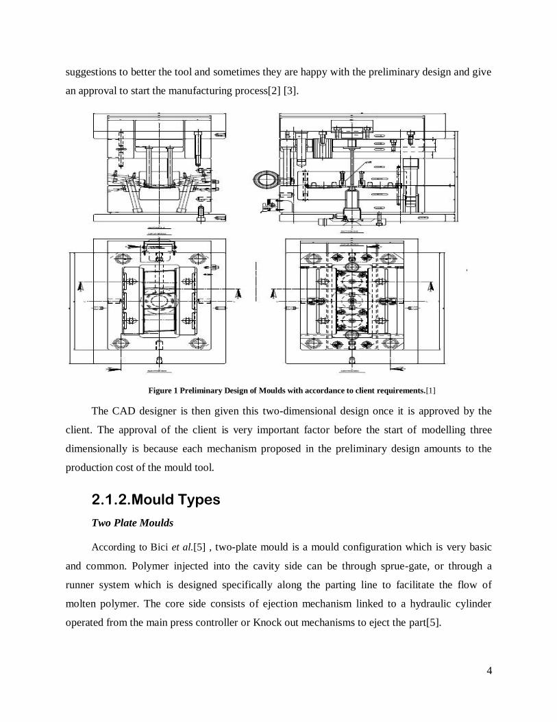
suggestions to better the tool and sometimes they are happy with the preliminary design and give
an approval to start the manufacturing process[2] [3].
Figure 1 Preliminary Design of Moulds with accordance to client requirements.[1]
The CAD designer is then given this two-dimensional design once it is approved by the
client. The approval of the client is very important factor before the start of modelling three
dimensionally is because each mechanism proposed in the preliminary design amounts to the
production cost of the mould tool.
2.1.2. Mould Types
Two Plate Moulds
According to Bici et al.[5] , two-plate mould is a mould configuration which is very basic
and common. Polymer injected into the cavity side can be through sprue-gate, or through a
runner system which is designed specifically along the parting line to facilitate the flow of
molten polymer. The core side consists of ejection mechanism linked to a hydraulic cylinder
operated from the main press controller or Knock out mechanisms to eject the part[5].

5
Figure 2 Two cavity Two Plate Mould.[6]
Three Plate Moulds
Kazmer et al.[3], states that three-plate mould configuration parts at two major locations
instead of one. A linking system between the three mould plates controls the mould-opening
sequence. The first stage of opening occurs along primary parting line disengaging the pinpoint
gates thus separating the moulded polymer from the cavity.
Next stage mould separates at the runner plate to facilitate removal of the runner system.
Ejection plates strips the runner from the retainer pins, and then polymer part ejects from the
mould[7]. Drawbacks of three plate moulds are assumedly mould complexity and large runners.
Small pinpoint gates required for automatic de-gating can result in high shear and lead to
material degradation. In stack moulds, cavities lie on two or more stacked parting lines[7][4].
Stack moulds produce more parts per cycle compared to two plate moulds in a given size
moulding press.
Figure 3 Three Plate Mould Cross section view with first stage(left) and second stage of opening(right)[6]

6
2.1.3. Moulding Undercuts
According to Dominik V Rosato et al.[8] say that undercuts, are usually part features that
prevent easy ejection, tend to increase mould complexity and lead to higher mould production
costs and maintenance costs. Thus it is always advised in design to redesign the undercut areas in
the part design stages[8].
Figure 4 Undercut Alternatives [6]
Undercut features that cannot be avoided through redesign usually require alternative
mechanisms to facilitate ejection[9][10]. The mechanisms namely are side-action slides, lifter
rails, jiggled pins, collapsible cores and unscrewing mechanisms. Side-action slides use cam pins
or hydraulic also known as pneumatic cylinders to retract undercut part before ejection. Cam-
pin-driven slides retract as the mould opens. When mould closes the cam pins return the slides to
their original position for the next injection cycle. Slides driven by hydraulic or pneumatic
cylinders can activate at any time during the moulding cycle.

7
Figure 5 Slide Action Side View [6]
As said by Fu et al.[11], says that Lifters are designed in a way that they move with an exit
angle during ejection to facilitate the overcoming process to avoid undercut in the part. Mould
design should include provisions to lubricate the moving part mechanism. Slides, cams,
collapsible cores, and unscrewing mechanisms add to the cost and complexity of the mould, and
mould maintenance cost[12][11]. Jiggler pin has angled surfaces to guide the pin away from the
undercut during ejection then return it to the moulding position as the ejector system retracts to
original position. Cautious part design can often eliminate troublesome undercuts.
Figure 6 Angled surface Jiggler Pins for Ejection[6]
2.1.4. Part Ejection
W. Ko et al [13].,say that moulds have ejector systems built into the moving half. The
ejection unit of the moulding press is used to activate part ejection systems. Specialized ejection
components, such as knockout (KO) pins, KO sleeves, or stripper plates, push mould ejector
plate to the part surface where they push the part out of the mould[2] [12].

8
Figure 7 Ejection Sliders.
Round knockout pin provides a simple and economical method for part ejection. They are
manufactured with high surface hardness. These KO pins are usually inexpensive and have a
long lifetime and rarely go through stress related breakage. Ejector blades, KO pins with a
rectangular cross section, operate same as standard round pins, but can be are difficult to position
and require higher maintenance. Drawbacks include that the KO pins usually are known to leave
witness marks or rings where the pin contacts the part. Many factors determine the amount of
ejector area needed, including the part geometry, mould finish, material-release characteristics,
and part temperature at the time of ejection[13].
2.1.5. Mould Shrinkage
According to D.Masato et al.[14] In “Analysis of the shrinkage of injection-moulded fibre-
reinforced thin-wall parts”, Polymers shrink significantly as they cool and solidify during the
moulding process. Designers make the mould cavity larger than the desired final part size to
compensate for shrinkage[15]. Mould shrinkage data published by the resin supplier for the
specific material can be used to estimate the amount of compensation needed. Published mould
shrinkage data, based on simple part geometries and standard moulding conditions, is calculated
using the following formula,
SHRINKAGE=
(eq. 1) [16].
Packing forces additional material into the mold to compensate for volume reduction,
lowering shrinkage[14][17]. Gate size, part thickness, and gate position can limit the level of

9
packing that can be achieved through processing adjustments. Large gate thickness and high
mould temperature delay gate freeze-off and promote higher levels of packing. The type and
duration of this constraint can affect net shrinkage between part features. Prototype moulds can
also be a good source of shrinkage values but may not replicate production conditions.
2.1.6. Features used to Design Mould Area
Part Area Analysis
B. Ravi and M. N. Srinivasan, state that one of the most important factors of mould design is
to know the part area because this influences a lot on the factors such as the mould tool size and
dimensions[4]. With the part area a CAD operator who does the preliminary design can place the
part on the right dimensions and is able to give dimensions to other components that constitute
the mould tool.
Figure 8 Part Area Analysis
Wall Thickness Analysis
This tool helps a lot in finding the right wall thickness and helping design the mould part of
the tool and the justification part next to the mould area. This helps in deciding how to make the
parting line. And this gives proper information on wall maximum and minimum wall thickness
too. The parting line is very important factor in deciding the mould quality[11].
10
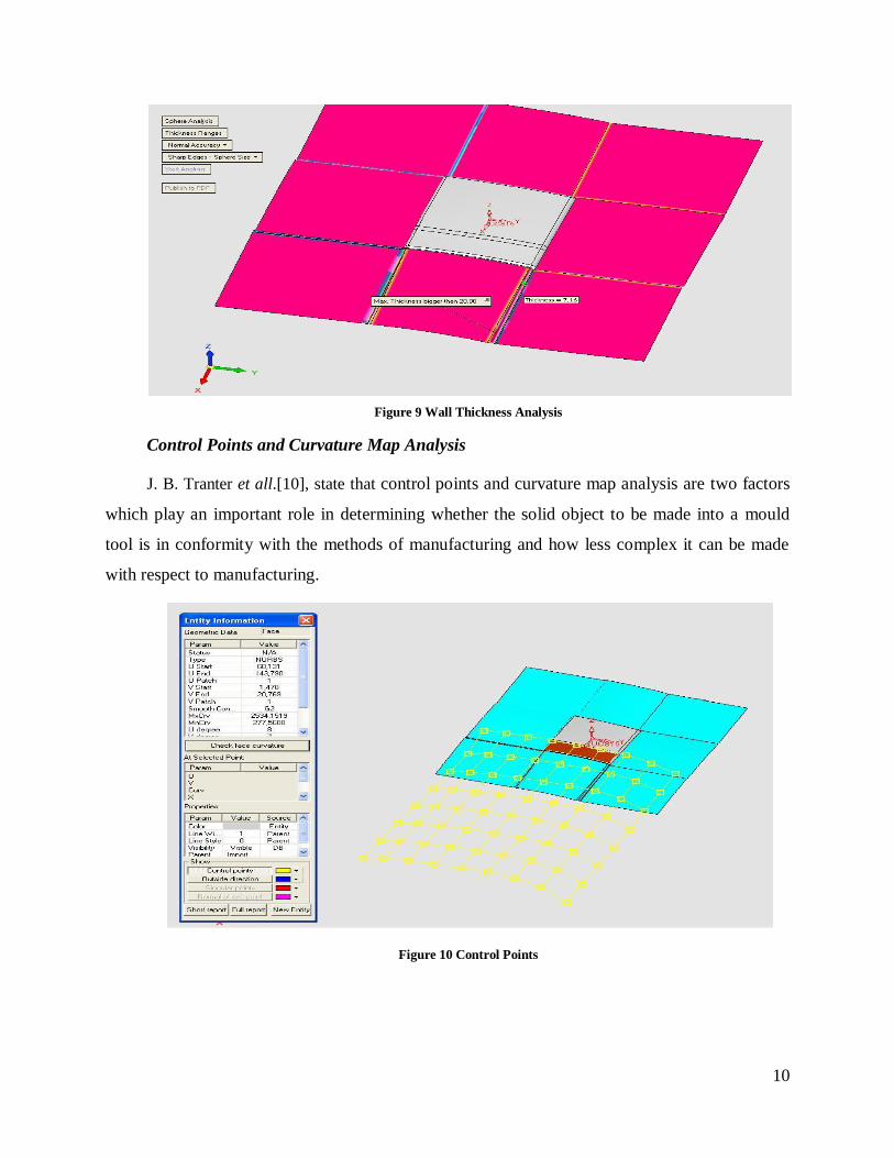
Figure 9 Wall Thickness Analysis
Control Points and Curvature Map Analysis
J. B. Tranter et all.[10], state that control points and curvature map analysis are two factors
which play an important role in determining whether the solid object to be made into a mould
tool is in conformity with the methods of manufacturing and how less complex it can be made
with respect to manufacturing.
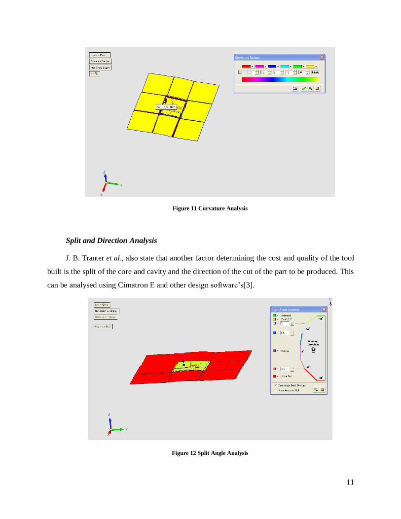
Figure 10 Control Points
11
Figure 11 Curvature Analysis
Split and Direction Analysis
J. B. Tranter et al., also state that another factor determining the cost and quality of the tool
built is the split of the core and cavity and the direction of the cut of the part to be produced. This
can be analysed using Cimatron E and other design software’s[3].
Figure 12 Split Angle Analysis
12
2.1.7. Mould Lifting
According to D. Kazmer in [3],Safety must be a primary consideration of the mould
designer. Mould maker is accountable for legal responsibility for any accident that may arise
because of an omission or poor design[16].There are four situations during which part or all of
the moulds is handled.
1. Machining a mould part (plates, heavy cavities and cores).
2. Assembling the mould (servicing and maintenance).
3. Mounting the mould in a machine.
4. Operating the mould.
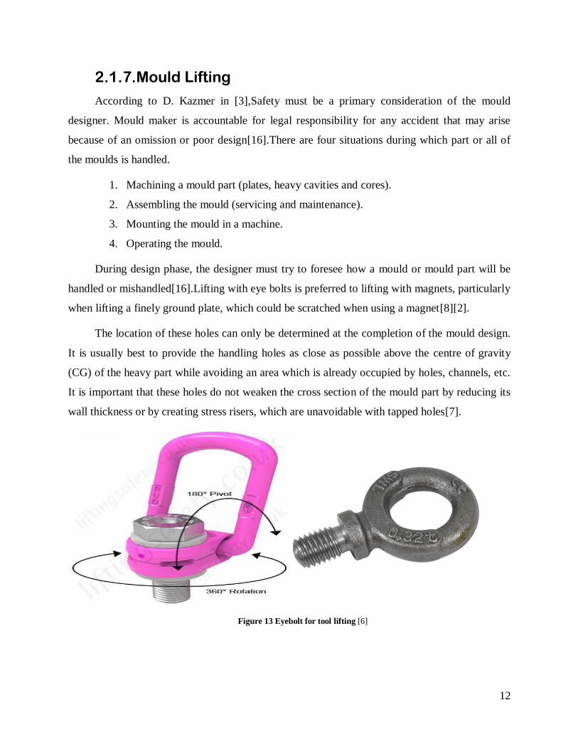
During design phase, the designer must try to foresee how a mould or mould part will be
handled or mishandled[16].Lifting with eye bolts is preferred to lifting with magnets, particularly
when lifting a finely ground plate, which could be scratched when using a magnet[8][2].
The location of these holes can only be determined at the completion of the mould design.
It is usually best to provide the handling holes as close as possible above the centre of gravity
(CG) of the heavy part while avoiding an area which is already occupied by holes, channels, etc.
It is important that these holes do not weaken the cross section of the mould part by reducing its
wall thickness or by creating stress risers, which are unavoidable with tapped holes[7].
Figure 13 Eyebolt for tool lifting [6]
13
2.2. CAM Programming
Modern tooling machines for mould making generally feature multi-axial CNC controls
and highly accurate positioning systems. The result is higher accuracy and greater efficiency
against rejects. Heat-treated work pieces may be finished to final strength. Various operations
such as cavity sinking by EDM can be replaced by complete milling operations and the process
chain thus shortened which helps in avoiding burn marks caused by EDM. Hard milling is used
both with conventional cutting-tool materials, such. For plastic injection moulds, hard metals or
coated hard metals prove to be optimum cutting-tool materials. To relieve stresses after roughing
annealing is done[18][19].
U. Consultant et al.[20], state that High speed cutting or HSC is characterized by high
cutting speeds and high spindle rotation speeds. Steel materials with hardness values of up to 62
HRC can also be machined with contemporary standard HSC millers. Better surface quality is
often achieved. Usually a combination of milling and eroding may also be performed. The
amount of milling should be maximized since the machining times are shorter on account of
higher removal capability[20].
2.2.1. Basic Steps in Programming
B. Schneiderman et al.[20], state that when machining the part using the CNC machine
tools, first prepare the program, and then operate the CNC machine by using the program.
First, prepare the program from a part drawing to operate the CNC machine tool. The
program is to be read into the CNC system. Mount the work pieces and tools on the machine and
operate the tools according to the programming. Before the actual programming, starts one must
decide machining plan, it includes:
i. Determination of work pieces machining range.
ii. Method of mounting work pieces on the machine tool.
iii. Machining sequence in every machining process.
iv. Machining tools and machining.

14
Figure 14 Machine Zero, Axis Coordination in CNC[21]
A CNC machine tool is provided with fixed position. Normally, tool change and
programming of absolute zero point is performed at this position. This position is called the
reference position. The tool can be moved to the reference position in two ways:
i. Manual reference position return.
ii. Automatic reference position return. [18].
Figure 15 Method of setting the two coordinate systems in the same position[21]
Figure 16 Absolute and Incremental Command[21]

15
Incremental command specifies the distance from the previous tool position to the next tool
position. The speed of the tool with respect to the work piece when the work piece is cut is called
the cutting speed. Cutting speed can be specified by the spindle speed[19] [22].
When a number is assigned to each tool and the number is specified in the program, the
corresponding tool is selected. When the tool is stored at location 01 in the ATC (automatic tool
control) magazine, the tool can be selected by specifying T01.This is called the tool function.
The function of specifying the on-off operations of the components of the machine are called the
miscellaneous function. The function is specified by an M code. For example, when M03 is
specified, the spindle is rotated clockwise at the specified spindle speed[23].
Figure 17 Tool Length Compensation[21]
X. M. Ding et al.[23], state that normally several tools are used for machining one work
piece. The tools have different tool length. This is achieved by setting the difference between the
length of the standard tool and the length of each tool in the CNC which is called tool length
compensation[20]. Because a cutter has a radius, the centre of the cutter path goes around the
work piece with the cutter radius deviated. This function is called cutter compensation

16
Figure 18 Cutter Compensation
2.2.2. CAM Formats
At present as explained by X. M. Ding et al. in, “Interference detection for 3-axis mould
machining”, the form of communication used by companies does not differ much from the
previously used formats. The one-piece design presupposes the modelling in CAD and, later, the
CAM development where the trajectories of the necessary operations, as well as the definition of
tools and parameters for machining are developed[23]. After CAD / CAM procedures for all the
work to be interpreted by the CNC machine, it is necessary to post-process all this information
through a post- compatible format with the equipment[8]. The figure 19 represents the sequence
of this whole process.
S. Zivanovic et al. [24],think that form of transmission has some drawbacks the program or
part, as this modification implies a new post-processing of the program or even a change of the
definitions of trajectories[25][24][20]. Some of the successful solutions were the SET in France,
the VDAFS in Germany and the IGES (Initial Graphics Exchange Specification) in the USA.
Later, ISO (International Standards Organization) created STEP (Standard for Product Model
Data) format, to create a support that a link with the various CAD software on the
market.[25].The benefits STEP-NC formats cause in the CAD / CAM / CNC connection.
1) 35% reduction in CAM planning time;
2) Reduction of 75% in the number of drawings sent from CAD to CAM;

17
3) 50% reduction in machining time;
4) Elimination of existing post-processors.
Figure 19 Flow of information chart[21]
2.2.3. Work’s Performed in Programming
While training in the CAM section, I was introduced to software named Work NC in which
I learnt the programming through the tutorial sections of the software itself to gain a rough
knowledge of how milling programming is done.

18
Figure 20 Toolpath preview in CAM
The milling follows a process for example, pre-roughing, roughing with tolerance, final
roughing, drilling, pre-finish, finish, final finishing etc, the software is loaded with the 3d model
of the metal to be machined. The programmer needs to choose a suitable machine and suitable
machining position and plane to accomplish good finish. The software enables to see material
that will be left over after each process.
Figure 21 Material left out for final finishing
The software also enables to view a simulation of the tool path programmed and to check if
there will be any interference while milling. This can be used to define the length of the tool and
the tool holder in general.

19
Figure 22 Simulation of tool path
2.3. CNC Milling
The basic concepts of computer numerical control (CNC) technology are discussed. The
important benefits to be derived from CNC operations are listed and explained[26].
2.3.1. Definition of CNC and Components
According to J.-Y. Jeng and M.-C. Lin, A computer numerical control (CNC) machine is an
NC machine with the added feature of an onboard computer. The onboard computer is often
referred to as the machine control unit or MCU. The MCU usually has an alphanumeric
keyboard for direct or manual data input (MDI) of part programs. Such programs are stored in
RAM or the random-access memory portion of the computer[27][28].

20
Figure 23 Components of modern CNC Systems[21]
Benefits of CNC
X. M. Ding et al. [23],conclude that computer numerical control offers new advantages
which are not not offered by older NC machines, such as reduction in the hardware is necessary
to add a machine function. Programs written via the main computer can be downloaded to any
CNC machine in the network. This is known as direct numerical control or DNC[23].
Necessary steps for CNC productivity
Computer numerical control machines can dramatically boost productivity. The CNC
manager, however, can only ensure such gains by first addressing several critical issues, such as
sufficient drill bits must be allocated for running CNC equipment. Careful production planning
must be studied because the hourly cost of operation of a CNC machine is usually higher than
that for conventional machines.
Modern Machine Controls
The machine control unit (MCU) contains a machine motion controller for controlling tool
movement. Many different types of controllers are available today, including Fanuc, Allen-
Bradley. All control systems, however, fall into two major categories: point-to-point and
continuous path.
21
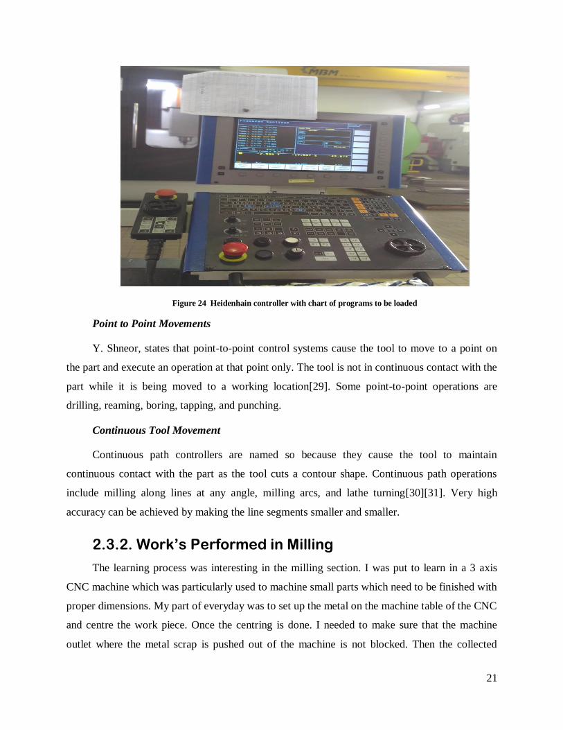
Figure 24 Heidenhain controller with chart of programs to be loaded
Point to Point Movements
Y. Shneor, states that point-to-point control systems cause the tool to move to a point on
the part and execute an operation at that point only. The tool is not in continuous contact with the
part while it is being moved to a working location[29]. Some point-to-point operations are
drilling, reaming, boring, tapping, and punching.
Continuous Tool Movement
Continuous path controllers are named so because they cause the tool to maintain
continuous contact with the part as the tool cuts a contour shape. Continuous path operations
include milling along lines at any angle, milling arcs, and lathe turning[30][31]. Very high
accuracy can be achieved by making the line segments smaller and smaller.
2.3.2. Work’s Performed in Milling
The learning process was interesting in the milling section. I was put to learn in a 3 axis
CNC machine which was particularly used to machine small parts which need to be finished with
proper dimensions. My part of everyday was to set up the metal on the machine table of the CNC
and centre the work piece. Once the centring is done. I needed to make sure that the machine
outlet where the metal scrap is pushed out of the machine is not blocked. Then the collected
22
scrap metal is transported to a place where it is collected and then an organization will come and
collect the scrap for recycling and reuse.
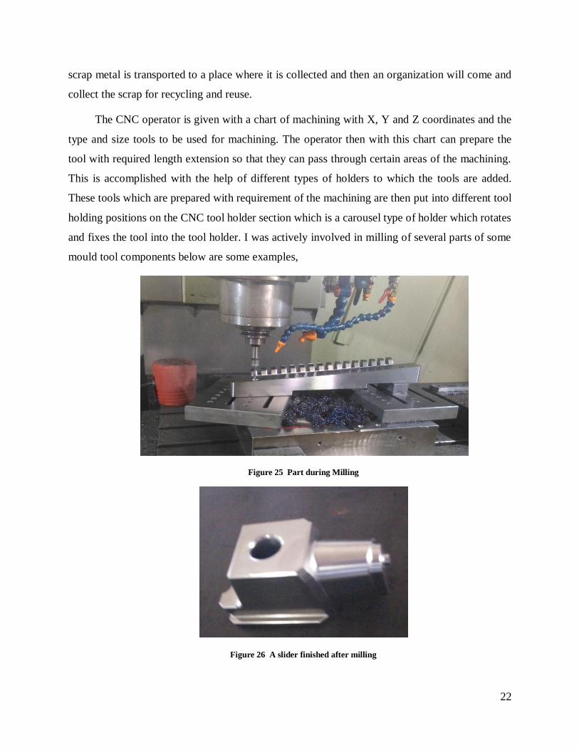
The CNC operator is given with a chart of machining with X, Y and Z coordinates and the
type and size tools to be used for machining. The operator then with this chart can prepare the
tool with required length extension so that they can pass through certain areas of the machining.
This is accomplished with the help of different types of holders to which the tools are added.
These tools which are prepared with requirement of the machining are then put into different tool
holding positions on the CNC tool holder section which is a carousel type of holder which rotates
and fixes the tool into the tool holder. I was actively involved in milling of several parts of some
mould tool components below are some examples,
Figure 25 Part during Milling
Figure 26 A slider finished after milling

23
2.4. Drilling
As described by VS Bykador [32]. Deep hole drilling has been used more and more widely
in injection moulds. This method requires a special machine or a deep hole drilling adaptor to
another machine, such as a milling machine. The drill operates in a horizontal plane. There are
four essential differences from ordinary drilling or milling machines,
1. The stroke of the machine (depth of hole) can be considerably largely.
2. The drill is supported very close to the work piece, as with a drill jig.
3. The cutting edge of the drill is directly pressure lubricated.
The drill works in one pass through solid material. It does not require pre-drilling.
Figure 27 Deep hole drilling in cross section [21]
Drill Material
ZB Bronzova says that the tip, at the working end of the drill, is made from a tungsten-
carbide alloy, which is much harder and longer lasting than high-speed steel. The head is brazed
to long steel tubing, which is held at its other end in the machine chuck. The tip is about 40 mm
long [32]. The cutting edge can be reground until the length of the remaining head is not long
enough to act as a guide within the hole. Shorter the tip, more risk of wandering.
Cutting Edge of Drill
D.Masato et al.[33], say that angles of the cutting lips depend on the material to be cut and
are about 300 on the short lip and 200 on the long lip[32][33]. As the drill progresses into the
work piece, the 3/4 cylindrical shape of the head and shank provides a better guide than the very
narrow margin on the twist drills. This helps to prevent wandering of the drill.
24
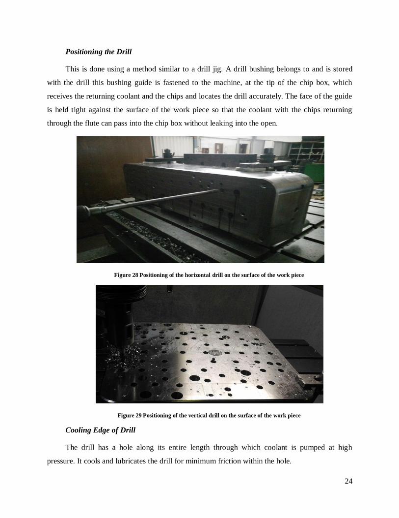
Positioning the Drill
This is done using a method similar to a drill jig. A drill bushing belongs to and is stored
with the drill this bushing guide is fastened to the machine, at the tip of the chip box, which
receives the returning coolant and the chips and locates the drill accurately. The face of the guide
is held tight against the surface of the work piece so that the coolant with the chips returning
through the flute can pass into the chip box without leaking into the open.
Figure 28 Positioning of the horizontal drill on the surface of the work piece
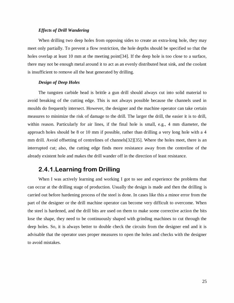
Figure 29 Positioning of the vertical drill on the surface of the work piece
Cooling Edge of Drill
The drill has a hole along its entire length through which coolant is pumped at high
pressure. It cools and lubricates the drill for minimum friction within the hole.
25
Effects of Drill Wandering
When drilling two deep holes from opposing sides to create an extra-long hole, they may
meet only partially. To prevent a flow restriction, the hole depths should be specified so that the
holes overlap at least 10 mm at the meeting point[34]. If the deep hole is too close to a surface,
there may not be enough metal around it to act as an evenly distributed heat sink, and the coolant
is insufficient to remove all the heat generated by drilling.
Design of Deep Holes
The tungsten carbide head is brittle a gun drill should always cut into solid material to
avoid breaking of the cutting edge. This is not always possible because the channels used in
moulds do frequently intersect. However, the designer and the machine operator can take certain
measures to minimize the risk of damage to the drill. The larger the drill, the easier it is to drill,
within reason. Particularly for air lines, if the final hole is small, e.g., 4 mm diameter, the
approach holes should be 8 or 10 mm if possible, rather than drilling a very long hole with a 4
mm drill. Avoid offsetting of centrelines of channels[32][35]. Where the holes meet, there is an
interrupted cut; also, the cutting edge finds more resistance away from the centreline of the
already existent hole and makes the drill wander off in the direction of least resistance.
2.4.1. Learning from Drilling
When I was actively learning and working I got to see and experience the problems that
can occur at the drilling stage of production. Usually the design is made and then the drilling is
carried out before hardening process of the steel is done. In cases like this a minor error from the
part of the designer or the drill machine operator can become very difficult to overcome. When
the steel is hardened, and the drill bits are used on them to make some corrective action the bits
lose the shape, they need to be continuously shaped with grinding machines to cut through the
deep holes. So, it is always better to double check the circuits from the designer end and it is
advisable that the operator uses proper measures to open the holes and checks with the designer
to avoid mistakes.
29
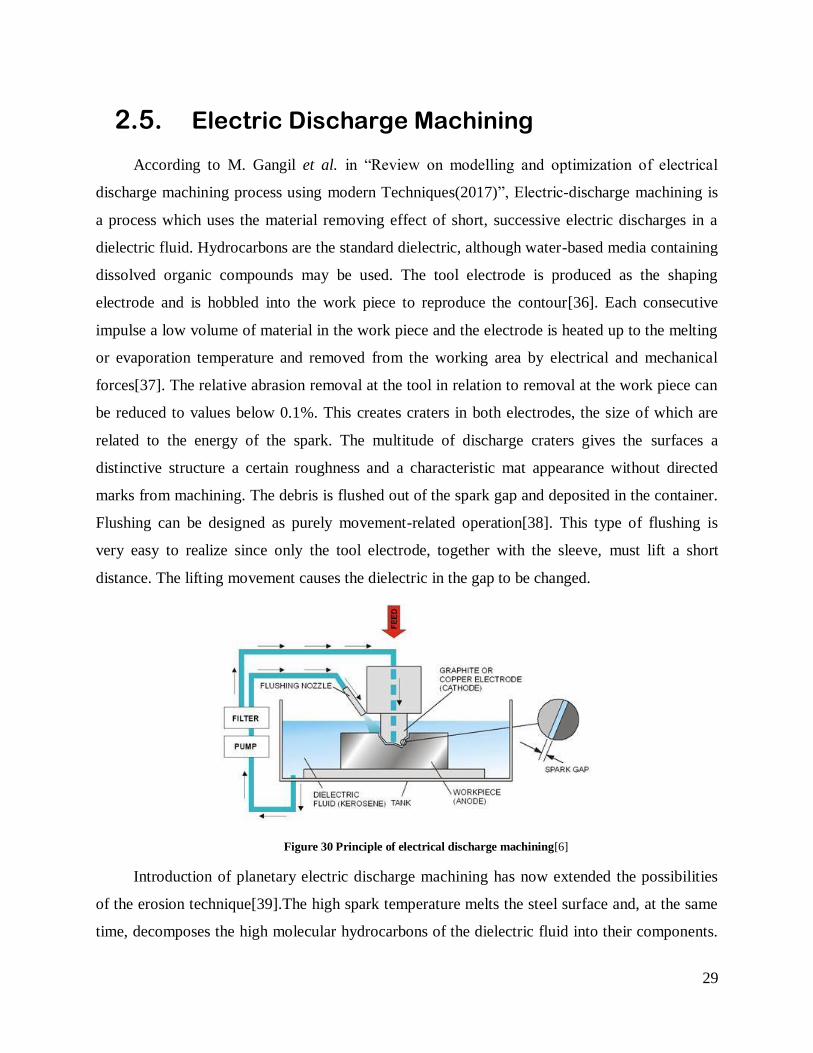
2.5. Electric Discharge Machining
According to M. Gangil et al. in “Review on modelling and optimization of electrical
discharge machining process using modern Techniques(2017)”, Electric-discharge machining is
a process which uses the material removing effect of short, successive electric discharges in a
dielectric fluid. Hydrocarbons are the standard dielectric, although water-based media containing
dissolved organic compounds may be used. The tool electrode is produced as the shaping
electrode and is hobbled into the work piece to reproduce the contour[36]. Each consecutive
impulse a low volume of material in the work piece and the electrode is heated up to the melting
or evaporation temperature and removed from the working area by electrical and mechanical
forces[37]. The relative abrasion removal at the tool in relation to removal at the work piece can
be reduced to values below 0.1%. This creates craters in both electrodes, the size of which are
related to the energy of the spark. The multitude of discharge craters gives the surfaces a
distinctive structure a certain roughness and a characteristic mat appearance without directed
marks from machining. The debris is flushed out of the spark gap and deposited in the container.
Flushing can be designed as purely movement-related operation[38]. This type of flushing is
very easy to realize since only the tool electrode, together with the sleeve, must lift a short
distance. The lifting movement causes the dielectric in the gap to be changed.
Figure 30 Principle of electrical discharge machining[6]
Introduction of planetary electric discharge machining has now extended the possibilities
of the erosion technique[39].The high spark temperature melts the steel surface and, at the same
time, decomposes the high molecular hydrocarbons of the dielectric fluid into their components.
30
The released carbon diffuses into the steel surface and produces very hard layers with carbide-
forming elements[40][41].
2.5.1. Wire EDM
C. Mascaraque-Ramirez states that, it is a very economical process for cutting through-hole
of arbitrary geometry in work pieces. The walls of the openings may be inclined to the plate
surface. The metal is removed by an electrical discharge without contact or mechanical action
between the work piece and a thin wire electrode[42]. The electrode is numerically controlled
and moved through the metal like a jig or band saw. Deionised water is the dielectric fluid and is
fed to the cutting area through coaxial nozzles. It is subsequently cleaned and regenerated in
separate equipment. It creates a wider spark gap, which improves flushing and the whole
process. The debris is lower. There are no solid decomposition products and no arc is generated
that would inevitably result in a wire break[43].
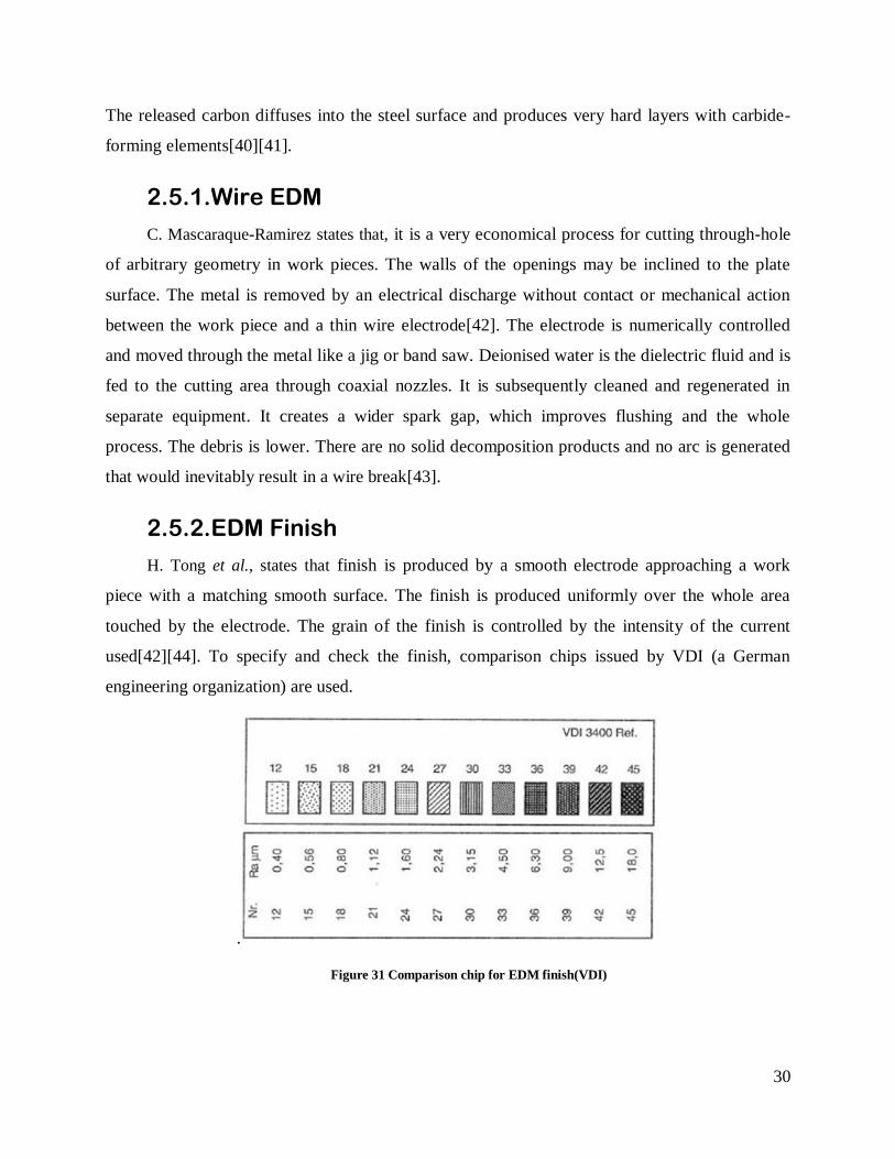
2.5.2. EDM Finish
H. Tong et al., states that finish is produced by a smooth electrode approaching a work
piece with a matching smooth surface. The finish is produced uniformly over the whole area
touched by the electrode. The grain of the finish is controlled by the intensity of the current
used[42][44]. To specify and check the finish, comparison chips issued by VDI (a German
engineering organization) are used.
.
Figure 31 Comparison chip for EDM finish(VDI)
31
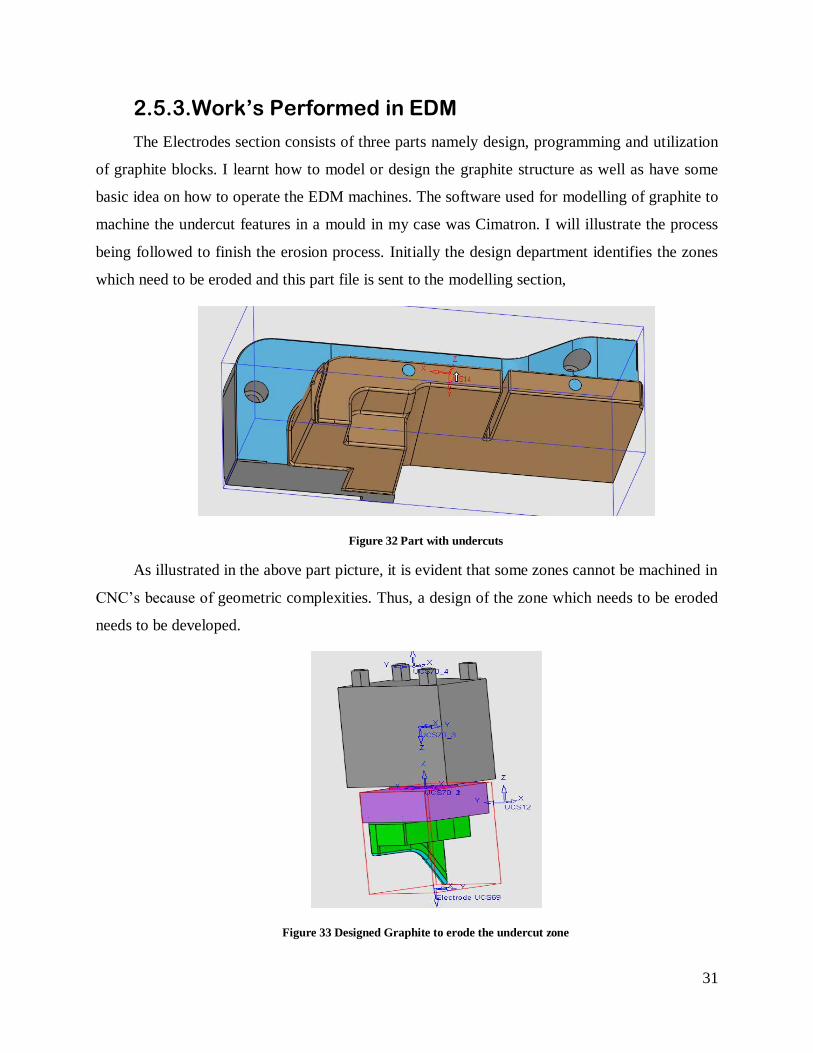
2.5.3. Work’s Performed in EDM
The Electrodes section consists of three parts namely design, programming and utilization
of graphite blocks. I learnt how to model or design the graphite structure as well as have some
basic idea on how to operate the EDM machines. The software used for modelling of graphite to
machine the undercut features in a mould in my case was Cimatron. I will illustrate the process
being followed to finish the erosion process. Initially the design department identifies the zones
which need to be eroded and this part file is sent to the modelling section,
Figure 32 Part with undercuts
As illustrated in the above part picture, it is evident that some zones cannot be machined in
CNC’s because of geometric complexities. Thus, a design of the zone which needs to be eroded
needs to be developed.
Figure 33 Designed Graphite to erode the undercut zone

32
Once this design is developed, a value of spark discharge to be machined is calculated in
accordance with the amount of material, type of material to be removed. The stock block
required to machine this is calculated using the software and then the block is machined using
special machines and drill bits to cut graphite. And once the graphite block is cut to the desired
shape an information chart is created with values and measurements to facilitate the erosion
process.
Figure 34 Positioning of Graphite in EDM machine
Usually a couple of same type of blocks are made to do the pre-finish and final finish
operations. They have different spark gap values. I was also to an extent able to gain knowledge
on trying to operate the machine, centre the mould tool, give commands for the machine to
execute consecutive operations without manual intervention. One such work that I did regularly
is program the machine to execute the consecutive erosion process and check if all the erosion is
achieving the desired results. Picture below shows one copper rod used to widen the gap in a drill
hole and consecutive copper rods waiting to work next.

33
Figure 35 Largening on gaps for ejector pins to move
2.6. Bench (Assembly)
2.6.1. Standard Mould Structure
C. Chen. et al.[45], state that, standard mould set consists of two clamping plates, two
cavity plates, an optional back plate, risers and an ejector set[46]. Core and cavity side are 3D-
CAD terms.
Figure 36 Standard mould set basic structure [6]
Ejector Set
Ejector set consists of two plates, an ejector retaining plate and an ejector plate. These are
fastened together with four bolts and the ejectors are placed between them[45][46].

34
Figure 37 Ejection Components[6]
Basic Guiding Elements
In the report by G. Schuh et al.[46], they state moving and fixed mould halves are guided
towards each other with different guiding elements. Basic guiding elements, which usually are a
part of the standard mould set, are guiding pillars, guiding sleeves and centring sleeves[47].
Figure 38 Guide pillar, Guide Sleeves, Centring elements[6]
Ejector Pins and Components for Ejection
Mercado Colmenero et al.[48], states that ejectors and Sprue pullers form basic part of
mould tool. There are different types of ejectors. The main types are round ejector pins, flat
ejector pins and ejector sleeves. Sprue pullers are specially shaped or specially placed ejectors,
which stick to the sprue and pull it out from the sprue bushing[49][50].Tilting ejectors are
suitable for moulding small back draft details like snap fits and small slots. Stripper plates are
very useful in ejecting high cup shaped parts[45].
35
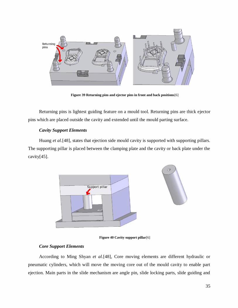
Figure 39 Returning pins and ejector pins in front and back positions[6]
Returning pins is lightest guiding feature on a mould tool. Returning pins are thick ejector
pins which are placed outside the cavity and extended until the mould parting surface.
Cavity Support Elements
Huang et al.[48], states that ejection side mould cavity is supported with supporting pillars.
The supporting pillar is placed between the clamping plate and the cavity or back plate under the
cavity[45].
Figure 40 Cavity support pillar[6]
Core Support Elements
According to Ming Shyan et al.[48], Core moving elements are different hydraulic or
pneumatic cylinders, which will move the moving core out of the mould cavity to enable part
ejection. Main parts in the slide mechanism are angle pin, slide locking parts, slide guiding and

36
slide. Moving faces are typically covered with wear plates[47]. In average size moulds and dies,
the typical core movement is less than 50 mm. Core pulling cylinder stroke varies between 100 –
250 mm.[50].
Figure 41 Core Guiding Elements[6]
2.6.2. Works Performed in Assembly
Bench is the most important part of mould tool building process. This is where all the
manufactured parts are assembled according to the design and then checked for any mistakes in
the production and is verified. The people who work in bench need to have good sensitivity with
metal parts as that helps them feel the connection of one part with another and check if it is
proper or if it needs more space or even if it does not occupy its intended space properly. I spent
around 2 months in the bench section where I was initially involved in rectification of adjust
plates, chest plates, sliders, Ejector pins Etc. I was working on number of grinding machines.
Figure 42 Grinding Machine [6]
These machines work in three axes X, Y, Z. The Z being the most judicially used axis because it
is removing the material and asserting it to proper dimensions. I had been assigned to rectify

37
adjust plates and chest plates, they were usually produced with tolerances of 2mm for example.
Once the 2D chart of the plate is available I was able to check the excess material in the plate
with the help of a Vernier calliper and I grinded them to make sure they don’t have excess
material.
Once they are in proper dimensions I either had to spray them with anti-rust oil or mount
them on the mould tool to check the fit of the plates. Usually only in the phase of testing the
mould closing this can be verified. I was also actively involved in rectification of many other
components like sliders, Jiggler pins, Ejectors etc, one of the work I accomplished in bench are
these image of a jiggler pin I rectified, as shown in figures 43,44,45,46.
Figure 43 Adjust plates

38
Figure 44 Plates once mounted
Another important phase where the mould is rectified, and the mould zone is checked in
when checking the closing and opening of the mould tool. The zones which do not have contact
with the other side are usually painted with red lead which passes on to the other side of the tool.
This is a very less density paint material it passes to the other side even if there is slightest
contact, which in turn helps in being able to identify the zones which need better finishing.
From my experience in bench section I feel the organization of work is important to meet
deadlines. My host organization always has plans for each part that goes into making the mould
tool which helps them work with time and quality if the final product.

39
Figure 45 Jiggler pin
Figure 46 Core side clamped on a machine to check contact.
2.7. Injection
As stated by H. Mianehrow and A. Abbasian, injection Moulding is a process of producing
polymer parts by injecting virgin polymers in molten state[10].Material for the part is fed to
machine via a heated barrel, mixed and forced into the mould cavity through a nozzle where it
cools and hardens to the configuration of the cavity. Usually the movable part has the extractor
mechanism to ease the part removal from the mould[51].

40
Figure 47 Injection Machine Layout[52]
2.7.1. Clamping
H. Mianehrow and A. Abbasian say that prior to the injection of the material into the mould,
the two halves of the mould must first be securely closed by the clamping unit. Each half of the
mould is attached to the injection moulding machine and one half is allowed to move[9][53]..
2.7.2. Injection
According to Li Xiping et al.[54], he says that raw(virgin) plastic material in the form of
pellets is fed into the injection moulding machine and pushed towards the mould cavity in
molten form by the injection unit[55]. The molten plastic is then injected into the mould very
quickly and the build-up of pressure packs and holds the material. The injection time can be
estimated by the shot volume, injection pressure, and injection power[9][56].
2.7.3. Cooling
Li Xiping also states that molten plastic that is inside the mould begins to cool as soon as it
makes contact with the interior mould surfaces[54]. As the plastic cools it solidifies into the
desired shape. During cooling some shrinkage of the part may occur. The packing of material in
the injection stage allows additional material to flow into the mould and reduce the amount of
visible shrinkage[56].
2.7.4. Ejection
41
N. Crisan et al.[56],conclude that, after sufficient time has passed, the cooled part may be
ejected from the mould by the ejection system, which is attached to the rear half of the mould.
When the mould is opened, a mechanism is used to push the part out of the mould. In order to
facilitate the ejection of the part, a mould release agent can be sprayed onto the surfaces of the
mould cavity prior to injection of the material[51].
2.7.5. Work’s Performed in Injection Section
This section constitutes the final part of Mould tool making process, which is testing of the
mould by injection of plastics. I had spent a month here trying to understand how the injection is
done and how the corrections are made to the Mould seeing the results of injection of plastics
into the Moulds. Initially I was watching how the Moulds are clamped on the injection machine
and how it is feed with virgin plastic material and how it is injected and the way the machine
works and to be able to find the mistakes in the tool by looking at the injected plastic output part.
The Geco plastic section had a total of 8 Injection machines with varying capabilities and ones
that can handle huge Mould to the size of 45 tons.
I have keenly observed the one of those machine for almost three weeks at the time in
Geco Plastics. Once the Mould is assembled in the benching section, it is transported here to be
injected with the material the client wants it to be injected with. In this testing the material
quantity is informed to the client in advance with relevance to the number of test sample parts
the client wants. The client on the other hand will courier the material in advance before testing
the Mould in injection so that there will be no delay to test the Mould.
The clients usually make visits to the company and spend lot of time checking the output
and give suggestions on where some rectifications need to be made for them to receive what they
desired in the first place. I was actively involved in initial stages of mould clamping and
preparing for injection like attaching the Mould in the machine to fixing the air and water and oil
valves correctly, feeding the injection machine with materials and the ratio of colour mix etc.
The materials which are injected must be injected at recommended temperature to be able to melt
and cool down without deformation. Once the injection cycle is done we have robotic arms to
remove the polymer part which is ejected from the tool and then we need to remove the sprue
and runner from the part.

42
These are saved safely to check if there is any problem with the runner or gate. The part is
checked for deformities such as excess material, along with any flash that has occurred, must be
trimmed from the part. For some types of material, such as thermoplastics, the scrap material that
results from this trimming can be recycled by being placed into a plastic grinder, also called
regrind machines or granulators, which regrinds the scrap material into pellets. Then the plastic
part is packed in requested quantities and sent to the client for final approval of the tool. And
another important part was to be very responsible about plastic waste as we know it is not a
substance which is healthy in decomposition. We had to put the plastic waste in a particular spot
where there are heaps of plastic waste materials that are collected over time. These materials are
then taken to a recycling place where it is recycled effectively and used somewhere else. Hence
this completes the process.
Figure 48 Mould Clamped on Injection Machine

43
3. Advances in Manufacturing
3.1. Additive Manufacturing
One factor where an injection mould tool takes lot of time and capital to be produced is
because of the complexity of designs and the limitations of the manufacturing process currently used.
With the exposure to this industry I have identified a zone where AM can be used. The client who is
a person who sends the article or the part for which the mould is produced, is not usually a single
part, it is co related to other parts and needs to mount or assemble properly to make the complete part
a successful one. In the injection mould tool industry it is more than common for the client to send
versions which are different once the production starts which leads to a huge increase in the cost of
the mould. This can be avoided in my opinion with the help of 3d printers and to check the assembly
of various components which form the main part before the production starts, so that the client can
make the required corrections to the part and saves a lot of capital on the tool.
Figure 49 Prototype of Mould part
T. Birtchnell et al., state that additive manufacturing (AM) is basically joining materials to
make objects from three-dimensional data which is achieved in a layer by layer process. Unlike
traditional processes which are versioned from subtractive processing of materials, additive
manufacturing reduces the wastage of materials[57]. Commonly known as 3D printing, AM’s
synonyms include rapid prototyping, additive fabrication, additive process, additive techniques,
44
additive layer manufacturing, layer manufacturing, freeform fabrication, solid freeform
fabrication and direct digital manufacturing. AM is a cost-effective and time efficient way to
produce low-volume, customized products with complex geometric features[58].
M. Despeisse says that parts produced by AM techniques have dimensional accuracy and
value. Since its inception, AM has evolved into a large group of processes, including Stereo
lithography (SLA), Fused Deposition Modelling (FDM), 3D Printing (3DP), Laminated Object
Manufacturing (LOM), Selective Laser Sintering (SLS), Selective Laser Melting (SLM), Laser
Metal Deposition (LMD), and others[59]. AM is a driving factor for innovation because of less
complexity and because it eliminates many constraints imposed by conventional machining, AM
intends to bring a change from Design for Manufacturing (DFM) to Manufacturing for Design
(MFD).
AM can produce parts in a layer by layer manner, which helps in achieving complex
structures which contrasts with subtractive manufacturing where we have design constraints,
needs of fixtures, diverse cooling. AM reduces the constraints and helps the designer to design
parts without having to compromise on the functionality of the end product[57].
3.1.1. Geometrical Freedom
T. Birtchnell et al,[59], think that AM is providing ease to designers in terms of part
complexity. With AM part complexity comes with no additional cost, as there is no need for
additional tooling[60]. The complexity can also be achieved with traditional methods like
injection moulding, but the complexity of the part comes along with high mould cost[59].
The dimensional accuracy can be explained as the difference in quality and structural
properties of the end product in comparison with the original design. In traditional processes like
grinding, general and specific geometrical tolerances are set as standards which have to be
considered while designing[60][57]. Likewise, it might become necessary to calculate and
introduce tolerances for designs manufactured by AM processes.
3.1.2. Time and cost Efficiency
M. Chapiro states that AM enables the production of complex shapes which otherwise need
assemblage of different parts if produced conventionally[61]. In addition, it is possible to

45
produce single-part assemblies while having integrated mechanisms. These parts are joined and
printed and are suspended by supporting material, Later the supporting material is removed in
post-processing operations[62]. Injection moulding is comparatively faster to produce big
batches of productions[63], whereas AM is significantly slower than injection moulding in terms
of producing parts, but AM can be advantageous in the area of prototyping and small batch
manufacturing as it reduces the cost and time by a very large margin[61].
3.1.3. Challenges and Scalability
M. Chapiro also states that AM is suitable for fabrication of products which have
customized features, low volume production and for product with geometrical complexity.
Typical markets that include the use of AM for manufacturing end products are aerospace, bio-
medical and high end automotive[64]. The cost and time of batch manufacturing by AM is much
more as compared to injection moulding, but in some cases cost and cycle time are not
significant as much as material saving, demand of product and geometrical complexity[65].
There exists an inherent trade-off within AM between layer resolution and the scale of the part to
be produced. To have good surface finish, the layer resolution must be high, which means small
layer thickness[66][63]. Decreasing the thickness of layer drastically affects the speed of
printing. For this reason, the layer resolution for most commercially available printers is ~0.1mm
to ~2.5mm.
3.1.4. AM Technologies
R. K. Vadivelu et al., present a study that says AM includes a wide range of technologies
that are capable of translating virtual solid model data into physical objects[62]. The model data
is usually available in Standard Tessellation Language (STL) format, which is broken down into
a series of 2D, thick cross-sections, which are then fed to the AM machine that adds up material
layer by layer to fabricate the physical part.AM is being used directly and indirectly to produce
prototype parts with suitable material properties for evaluating and testing. Direct fabrication of
functional end-use products is becoming the main trend of AM technology, and it is being
increasingly implemented to manufacture parts in small or medium quantities [67].
3.1.5. Advantages of AM over Injection Moulds

46
i. No need for costly tools or punches.
ii. No geometrical constraints.
iii. No setup time needed.
iv. Speed and ease of designing and modifying products.
v. No scrap, milling or sanding required.
3.1.6. Limitations of AM over Injection Moulds
i. Higher costs for large production run relative to injection moulding and other
technologies.
ii. Reduced choice of materials and surface finish.
iii. Lower precision as compared to other technologies.
iv. Limited strength, resistance to heat and moisture.
T. Böhme et al. conclude that, limitations of additive manufacturing are the main reasons
due to which injection moulding cannot be replaced by any AM technologies at this point of
time. Injection moulding provides series of part production which AM processes are not able to
provide at lower costs. Even though, for some designs the total cycle time (including setup time)
of AM processes to produce parts is less, the cost of the process plays much more significant role
in this area of interest. A lot of research is being made to combine the additive and the
subtractive machining processes to optimize the material usage and the cost of the process. The
system using both additive and subtractive manufacturing processes is called as hybrid system of
manufacturing[68].
3.2. Rapid Tooling for Prototyping
As explained by H. Yu et al., traditional injection moulding is less expensive for
manufacturing polymer products in high quantities but in contrast, RP processes are faster and
less expensive when produced in relatively small quantities[69]. However, there exists a small
area where neither the use of injection moulding or traditional rapid prototyping process can be
47
justified. Rapid tooling (RT) techniques, an derivative of rapid prototyping process, allow the
manufacture of production tools rather than actual part itself[70].
3.2.1. CASE 1
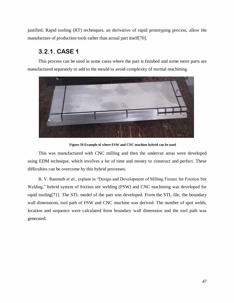
This process can be used in some cases where the part is finished and some more parts are
manufactured separately to add to the mould to avoid complexity of normal machining.
Figure 50 Example of where FSW and CNC machine hybrid can be used
This was manufactured with CNC milling and then the undercut areas were developed
using EDM technique, which involves a lot of time and money to construct and perfect. These
difficulties can be overcome by this hybrid processes.
B. V. Ramnath et al., explain in “Design and Development of Milling Fixture for Friction Stir
Welding,” hybrid system of friction stir welding (FSW) and CNC machining was developed for
rapid tooling[71]. The STL model of the part was developed. From the STL file, the boundary
wall dimensions, tool path of FSW and CNC machine was derived. The number of spot welds,
location and sequence were calculated from boundary wall dimension and the tool path was
generated.

48
Figure 51 Detailed process steps of rapid tooling system[52]
An adhesive is applied on the areas of boundary was cross section and mould cross section.
The adhesively bonded plate is then spot welded using friction stir spot welding. This is because
the strength of adhesives alone are assumed to be insufficient to withstand the forces of friction
stir welding process[70]. A new layer is deposited by use of friction stir welding of cross-section
and then the CNC machining of 3D layer shape is done. This process is repeated till the built is
complete. Later the boundary walls are removed if needed.
3.2.2. CASE 2
One of the most difficult and hard part in designing a mould tool is to provide it with proper
cooling channels according to the structure of the mould zone and in the process the designer must
think in advance to how it can be machined. Due to restrictions in axial movements and other factors
a designer does not have geometrical freedom to provide the best possible cooling channel, instead
he provides best possible machinable and best possible cooling channel with respect to machining.
One of the cooling channels I designed is shown in figure 51. This cooling channel will almost
achieve what it is intended to, but it was done with the manufacturing possibility in mind and not
with the suitable cooling channel for the mould zone itself. These limitations can be very well
avoided by conformal cooling process.

49
Figure 52 ISO view of traditional cooling channel
H.-S. Park and X.-P. Dang, say that hybrid systems can also be used for making conformal
cooling systems in inserts and other parts of moulds[72]. The conformal cooling system is a term
for cooling channels which conforms to the contours of the inserts or cavity of injection
moulding tool.
Figure 53 Conventional cooling system and Conformal cooling system[52]
With conformal cooling systems, it is possible to get better dimensional accuracy of the
moulded part, better mechanical properties of the part and a reduced cycle time of injection
moulding up to 40%. Conformal cooling system is not possible with conventional machining
systems due to design constraints but with hybrid manufacturing, one can make moulds with
conformal cooling channels.

50
3.3. Future of AM
D. R. Eyers and A. T. Potter in “Industrial Additive Manufacturing systems perspective,”
conclude that promise of AM is based on products such as dental, medical and low turnover
replacement parts. These goods are typically ordered in unique configuration and in very small
quantities. Significant advantage of AM is a firm’s ability to quickly and cost effectively supply
low-demanding products without risk of carrying an unsold finished goods inventory[73]. With
AM, the risk of poor design is based on wasted design time rather than inventory investment.
J. K. Watson and K. M. B. Taminger say that the promise of AM lies in separation of
product design from product manufacturing. As AM evolves, consumers will be able to purchase
designs online and then build products at home. Appliance companies can also contact out the
manufacturing of spare parts to third parties, which will then build parts based on CAD software
provided by the appliance manufacturer. Since no inventory will be kept, the cost of parts will be
less. Within the next 5 years or so, one can reasonable forecast a number of significant 3D
printing supply chain development on not only the design side but also on the production
side[74].
S. Bose et al., think that in the long term, the range of industrial 3D printing applications
will increase drastically as new AM machines will be available to accommodate larger products
and achieve great levels of precision. There should be significant decline in materials and
machinery cost as more individuals and firms adopt this technology. Additionally, the usage of
AM will expand due to the availability of materials with greater strength and resistance to heat
and moisture. Material cost will also decrease as result of higher market demand. The future
holds great promise for AM as a technology and for end users as a result.[75]

51
4. Conclusion
From my learning experience in the mould industry I have attained a brief overview of how
the industry is working and some sectors where it can be developed. The Portuguese mould
industry must try and invest in countries where new manufacturing plants are being developed to
be in touch with the growing demands of the mould industry. The organisation of a mould
company is very important; this organisation differentiates successful companies from the ones
that are not able to find many projects. And the industry must also look into the advances in
production techniques which will help the industry to cope up with the pace at which the
technologies are developed, because when other companies invest and produce with latest
advancements in technology they gain a lot with time. If a company does not want to invest on
modern equipments it will be left behind in the manufacturing capabilities.
We are on the brink of industrial revolution where emerging and existing companies are
thinking how traditional manufacturing will be transformed. The factors that are already bringing
about this change and are most likely to do so in the next few decades, are discussed above along
with some challenges they bring.
D. R. Eyers and A. T. Potter, think that additive manufacturing processes coming into the
manufacturing industry at a great pace[76]. Currently we have a substantial percentage of
printers in the market but due to high cost their usage is not meeting the potential of this
manufacturing technique.Also, the development of hybrid processes of rapid prototyping and
tooling is making an impact on the way the moulds are being made. The replacement of moulds
with 3D printers is not a solution for coming few years, in terms of mass production, but AM
processes is definitely a good deal to investigate and invest time on.

52
This page was intetionally left blank

53
5. References
[1] GECO Lda, “GECO.” [Online]. Available: https://geco-moldes.pt/. [Accessed: 12-Dec-
2016].
[2] M. T. MacLean-Blevins, “6 - Preliminary detailed design,” in Designing Successful
Products with Plastics, M. T. MacLean-Blevins, Ed. William Andrew Publishing, 2018,
pp. 127–195.
[3] T. Wu, S. A. Jahan, Y. Zhang, J. Zhang, H. Elmounayri, and A. Tovar, “Design
Optimization of Plastic Injection Tooling for Additive Manufacturing,” Procedia Manuf.,
vol. 10, pp. 923–934, 2017.
[4] B. Ravi and M. N. Srinivasan, “Decision criteria for computer-aided parting surface
design,” Comput. Des., vol. 22, no. 1, pp. 11–18, 1990.
[5] M. Bici, G. B. Broggiato, F. Campana, and A. Dughiero, “Computer Aided Inspection
Procedures to Support Smart Manufacturing of Injection Moulded Components,”
Procedia Manuf., vol. 11, no. June, pp. 1184–1192, 2017.
[6] Ibilonja, “Ibilonja.” [Online]. Available: www.ibilonjavirtual.com. [Accessed: 20-Jun-
2017].
[7] D. O. Kazmer, “Injection Mold Design Engineering,” in Injection Mold Design
Engineering (Second Edition), Second Edi., D. O. Kazmer, Ed. Hanser, 2016, pp. I–
XXIV.
[8] D. V Rosato, D. V Rosato, and M. V Rosato, “4 - INJECTION MOLDING,” in Plastic
Product Material and Process Selection Handbook, D. V Rosato, D. V Rosato, and M. V
Rosato, Eds. Oxford: Elsevier, 2004, pp. 192–226.
[9] W. M. Cheung, J. T. Leong, and P. Vichare, “Incorporating lean thinking and life cycle
assessment to reduce environmental impacts of plastic injection moulded products,” J.
Clean. Prod., vol. 167, pp. 759–775, 2018.
[10] J. B. Tranter, P. Refalo, and A. Rochman, “Towards sustainable injection molding of ABS
plastic products,” J. Manuf. Process., vol. 29, pp. 399–406, 2017.
54
[11] M. W. Fu, J. Y. H. Fuh, and A. Y. C. Nee, “Undercut feature recognition in an injection
mould design system,” Comput. Des., vol. 31, no. 12, pp. 777–790, 1999.
[12] J. Q. Ran and M. W. Fu, “Design of internal pins in injection mold CAD via the automatic
recognition of undercut features,” Comput. Des., vol. 42, no. 7, pp. 582–597, 2010.
[13] W. Ko, P. Wang, and S. Lachhman, “Chapter 6 - System integration and packaging,” in
Implantable Biomedical Microsystems, S. Bhunia, S. J. A. Majerus, and M. Sawan, Eds.
Oxford: William Andrew Publishing, 2015, pp. 113–136.
[14] D. Masato, J. Rathore, M. Sorgato, S. Carmignato, and G. Lucchetta, “Analysis of the
shrinkage of injection-molded fiber-reinforced thin-wall parts,” Mater. Des., vol. 132, pp.
496–504, 2017.
[15] C. K. Mok, K. S. Chin, and H. Lan, “An Internet-based intelligent design system for
injection moulds,” Robot. Comput. Integr. Manuf., vol. 24, no. 1, pp. 1–15, 2008.
[16] Seiichi Honma, Injection molding technology exploiting the material characteristics.
2011.
[17] B. J. A. R. Tony, S. Karthikeyen, and B. J. A. R. Alex, “Injection Mold Design Parameters
Calculation Using Pro/Plastic Advisor for Spur Gear,” Mater. Today Proc., vol. 4, no. 10,
pp. 11118–11125, 2017.
[18] G. Bertacchi and N. Pastorini, “The computer integrated path to production of plastic
parts,” Mater. Des., vol. 6, no. 6, pp. 313–315, 1985.
[19] P. Roughing, “Practical Solutions to Common Machining Problems,” no. August, pp. 1–3,
2010.
[20] U. Consultant, B. Shneiderman, K. T. Smith, and N. K. Newspaper, “The benefits of ‘
ease of use ’ in CAD / CAM software .,” vol. 11, no. 1998, pp. 1–5, 2007.
[21] Sugino, “Drill.” [Online]. Available: http://www.sugino.com. [Accessed: 22-Sep-2016].
[22] R. Endl and J. Jaje, “The challenges for CAM systems and users in 5-axis machining,”
2012.
[23] X. M. Ding, J. Y. H. Fuh, and K. S. Lee, “Interference detection for 3-axis mold
machining,” Comput. Des., vol. 33, no. 8, pp. 561–569, 2001.

55
[24] S. Zivanovic, N. Slavkovic, and D. Milutinovic, “An approach for applying STEP-NC in
robot machining,” Robot. Comput. Integr. Manuf., vol. 49, pp. 361–373, 2018.
[25] Y. Guo, J. Heller, T. J. R. Hughes, M. Ruess, and D. Schillinger, “Variationally consistent
isogeometric analysis of trimmed thin shells at finite deformations, based on the STEP
exchange format,” Comput. Methods Appl. Mech. Eng., 2018.
[26] X. Zhao, Y. Pan, C. Zhou, Y. Chen, and C. C. L. Wang, “An integrated CNC
accumulation system for automatic building-around-inserts,” J. Manuf. Process., vol. 15,
no. 4, pp. 432–443, 2013.
[27] J.-Y. Jeng and M.-C. Lin, “Mold fabrication and modification using hybrid processes of
selective laser cladding and milling,” J. Mater. Process. Technol., vol. 110, no. 1, pp. 98–
103, 2001.
[28] D. M. Yakovleva, G. F. Mukhametzyanova, and L. R. Kharisov, “The Research of
Stresses in the Molds of Injection Molding Machines,” Procedia Eng., vol. 150, pp. 453–
457, 2016.
[29] Y. Shneor, “Reconfigurable machine tool: CNC machine for milling, grinding and
polishing,” Procedia Manuf., vol. 21, pp. 221–227, 2018.
[30] A. Aramcharoen and P. T. Mativenga, “Critical factors in energy demand modelling for
CNC milling and impact of toolpath strategy,” J. Clean. Prod., vol. 78, pp. 63–74, 2014.
[31] W. de Oliveira Leite, J. C. C. Rubio, J. G. Duduch, and P. E. M. de Almeida, “Correcting
geometric deviations of CNC Machine-Tools: An approach with Artificial Neural
Networks,” Appl. Soft Comput., vol. 36, pp. 114–124, 2015.
[32] V. S. Bykador and Z. E. B. (Bronzova), “Bifurcations of Deep Hole Drilling Process,”
Procedia Eng., vol. 206, pp. 151–156, 2017.
[33] D. Masato, M. Sorgato, P. Parenti, M. Annoni, and G. Lucchetta, “Impact of deep cores
surface topography generated by micro milling on the demolding force in micro injection
molding,” J. Mater. Process. Technol., vol. 246, pp. 211–223, 2017.
[34] O. Bologa, R.-E. Breaz, S.-G. Racz, and M. Crenganiş, “Decision-making Tool for
Moving from 3-axes to 5-axes CNC Machine-tool,” Procedia Comput. Sci., vol. 91, pp.

56
184–192, 2016.
[35] M. Moayyedian, K. Abhary, and R. Marian, “New Design Feature of Mold in Injection
Molding For Scrap Reduction,” Procedia Manuf., vol. 2, pp. 241–245, 2015.
[36] W. G. Frizelle, “10 - Injection Molding Technology,” in Applied Plastics Engineering
Handbook (Second Edition), Second Edi., M. Kutz, Ed. William Andrew Publishing,
2017, pp. 191–202.
[37] E. Uhlmann, M. Röhner, M. Langmack, and T.-M. Schimmelpfennig, “Chapter 4 - Micro-
electrical Discharge Machining,” in Micromanufacturing Engineering and Technology
(Second Edition), Second Edi., Y. Qin, Ed. Boston: William Andrew Publishing, 2015, pp.
81–105.
[38] M. Gangil, M. K. Pradhan, and R. Purohit, “Review on modelling and optimization of
electrical discharge machining process using modern Techniques,” Mater. Today Proc.,
vol. 4, no. 2, Part A, pp. 2048–2057, 2017.
[39] S. A. Lawal and M. B. Ndaliman, “Surface Roughness Characteristics in Finish Electro-
Discharge Machining Process,” in Reference Module in Materials Science and Materials
Engineering, Elsevier, 2017.
[40] A. W. J. Hsue and Y. F. Chang, “Toward synchronous hybrid micro-EDM grinding of
micro-holes using helical taper tools formed by Ni-Co/diamond Co-deposition,” J. Mater.
Process. Technol., vol. 234, pp. 368–382, 2016.
[41] K. T. Chiang, F. P. Chang, and D. C. Tsai, “Modeling and analysis of the rapidly
resolidified layer of SG cast iron in the EDM process through the response surface
methodology,” J. Mater. Process. Technol., vol. 182, no. 1–3, pp. 525–533, 2007.
[42] C. Mascaraque-Ramirez and P. Franco, “Experimental Study of Surface Finish during
Electro-Discharge Machining of Stainless Steel,” Procedia Eng., vol. 132, pp. 679–685,
2015.
[43] L. Romoli, C. A. A. Rashed, and M. Fiaschi, “Experimental characterization of the inner
surface in micro-drilling of spray holes: A comparison between ultrashort pulsed laser and
EDM,” Opt. Laser Technol., vol. 56, pp. 35–42, 2014.

57
[44] H. Tong, Y. Li, L. Zhang, and B. Li, “Mechanism design and process control of micro
EDM for drilling spray holes of diesel injector nozzles,” Precis. Eng., vol. 37, no. 1, pp.
213–221, 2013.
[45] C. Chen, Y. Wang, H. Ou, Y. He, and X. Tang, “A review on remanufacture of dies and
moulds,” J. Clean. Prod., vol. 64, pp. 13–23, 2014.
[46] G. Schuh, M. Pitsch, N. Komorek, M. Schippers, and M. Salmen, “Cutting manufacturing
failure costs in the tool and die industry by implementing a knowledge transfer system to
avoid and correct mistakes more effectively,” Procedia CIRP, vol. 16, pp. 80–85, 2014.
[47] K. McGlinn, B. Yuce, H. Wicaksono, S. Howell, and Y. Rezgui, “Usability evaluation of
a web-based tool for supporting holistic building energy management,” Autom. Constr.,
vol. 84, no. November 2016, pp. 154–165, 2017.
[48] J. M. Mercado-Colmenero, M. A. Rubio-Paramio, A. Vizan-Idoipe, and C. Martin-
Doñate, “A new procedure for the automated design of ejection systems in injection
molds,” Robot. Comput. Integr. Manuf., vol. 46, pp. 68–85, 2017.
[49] L. P. C. D. S. Andrade, C. V. Ferreira, R. C. Da Silva, and J. D. O. Gomes, “Strategic
Management Method for the Incubation Process of Industrial Companies: Case Study of
the Tooling Industry in Brazil,” Procedia CIRP, vol. 41, pp. 129–134, 2016.
[50] F. Klocke, K. Arntz, M. Teli, K. Winands, M. Wegener, and S. Oliari, “State-of-the-art
Laser Additive Manufacturing for Hot-work Tool Steels,” Procedia CIRP, vol. 63, pp.
58–63, 2017.
[51] M. S. Butt et al., “Mechanical and degradation properties of biodegradable Mg
strengthened poly-lactic acid composite through plastic injection molding,” Mater. Sci.
Eng. C, vol. 70, pp. 141–147, 2017.
[52] mould technology, “Injection machine.” [Online]. Available: http://mould-
technology.blogspot.pt/. [Accessed: 16-Oct-2017].
[53] H. Mianehrow and A. Abbasian, “Energy monitoring of plastic injection molding process
running with hydraulic injection molding machines,” J. Clean. Prod., vol. 148, pp. 804–
810, 2017.

58
[54] X. Li, F. Liu, N. Gong, P. Huang, and C. Yang, “Enhancing the joining strength of
injection-molded polymer-metal hybrids by rapid heating and cooling,” J. Mater. Process.
Technol., vol. 249, pp. 386–393, 2017.
[55] C. Wang, M. Huang, C. Shen, and Z. Zhao, “Warpage prediction of the injection-molded
strip-like plastic parts,” Chinese J. Chem. Eng., vol. 24, no. 5, pp. 665–670, 2016.
[56] N. Crisan, S. Descartes, Y. Berthier, J. Cavoret, D. Baud, and F. Montalbano,
“Tribological assessment of the interface injection mold/plastic part,” Tribol. Int., vol.
100, pp. 388–399, 2016.
[57] M. Despeisse et al., “Unlocking value for a circular economy through 3D printing: A
research agenda,” Technol. Forecast. Soc. Change, vol. 115, pp. 75–84, 2017.
[58] M. Yampolskiy, A. Skjellum, M. Kretzschmar, R. A. Overfelt, K. R. Sloan, and A.
Yasinsac, “Using 3D printers as weapons,” Int. J. Crit. Infrastruct. Prot., vol. 14, pp. 58–
71, 2016.
[59] T. Birtchnell, T. Böhme, and R. Gorkin, “3D printing and the third mission: The
university in the materialization of intellectual capital,” Technol. Forecast. Soc. Change,
vol. 123, pp. 240–249, 2017.
[60] G. D. Goh, S. Agarwala, G. L. Goh, V. Dikshit, S. L. Sing, and W. Y. Yeong, “Additive
manufacturing in unmanned aerial vehicles (UAVs): Challenges and potential,” Aerosp.
Sci. Technol., vol. 63, pp. 140–151, 2017.
[61] O. H. Paydar, C. N. Paredes, Y. Hwang, J. Paz, N. B. Shah, and R. N. Candler,
“Characterization of 3D-printed microfluidic chip interconnects with integrated O-rings,”
Sensors Actuators, A Phys., vol. 205, pp. 199–203, 2014.
[62] M. Chapiro, “Current achievements and future outlook for composites in 3D printing,”
Reinf. Plast., vol. 60, no. 6, pp. 372–375, 2016.
[63] A. Munaz, R. K. Vadivelu, J. St. John, M. Barton, H. Kamble, and N.-T. Nguyen, “Three-
dimensional printing of biological matters,” J. Sci. Adv. Mater. Devices, vol. 1, no. 1, pp.
1–17, 2016.
[64] D. Radenkovic, A. Solouk, and A. Seifalian, “Personalized development of human organs
59
using 3D printing technology,” Med. Hypotheses, vol. 87, pp. 30–33, 2016.
[65] L. C. Hwa, S. Rajoo, A. M. Noor, N. Ahmad, and M. B. Uday, “Recent advances in 3D
printing of porous ceramics: A review,” Curr. Opin. Solid State Mater. Sci., vol. 21, no. 6,
pp. 323–347, 2017.
[66] P. Tran, T. D. Ngo, A. Ghazlan, and D. Hui, “Bimaterial 3D printing and numerical
analysis of bio-inspired composite structures under in-plane and transverse loadings,”
Compos. Part B Eng., vol. 108, pp. 210–223, 2017.
[67] S. Lim, V. L. Prabhu, M. Anand, and L. A. Taylor, “Extra-terrestrial construction
processes – Advancements, opportunities and challenges,” Adv. Sp. Res., vol. 60, no. 7,
pp. 1413–1429, 2017.
[68] T. Hofstätter, D. B. Pedersen, G. Tosello, and H. N. Hansen, “Applications of Fiber-
Reinforced Polymers in Additive Manufacturing,” Procedia CIRP, vol. 66, pp. 312–316,
2017.
[69] H. Yu, B. Zheng, and X. Lai, “A modeling study of welding stress induced by friction stir
welding,” J. Mater. Process. Technol., vol. 254, pp. 213–220, 2018.
[70] B. V. Ramnath, C. Elanchezhian, S. Rajesh, S. J. Prakash, B. M. Kumaar, and K.
Rajeshkannan, “Design and Development of Milling Fixture for Friction Stir Welding,”
Mater. Today Proc., vol. 5, no. 1, Part 1, pp. 1832–1838, 2018.
[71] M. A. WAHID, Z. A. KHAN, and A. N. SIDDIQUEE, “Review on underwater friction
stir welding: A variant of friction stir welding with great potential of improving joint
properties,” Trans. Nonferrous Met. Soc. China, vol. 28, no. 2, pp. 193–219, 2018.
[72] H.-S. Park and X.-P. Dang, “Development of a Smart Plastic Injection Mold with
Conformal Cooling Channels,” Procedia Manuf., vol. 10, pp. 48–59, 2017.
[73] S. Bose, D. Ke, H. Sahasrabudhe, and A. Bandyopadhyay, “Additive manufacturing of
biomaterials,” Prog. Mater. Sci., vol. 93, pp. 45–111, 2018.
[74] J. S. Cuellar, G. Smit, D. Plettenburg, and A. Zadpoor, “Additive manufacturing of non-
assembly mechanisms,” Addit. Manuf., vol. 21, pp. 150–158, 2018.
[75] D. R. Eyers and A. T. Potter, “Industrial Additive Manufacturing: A manufacturing

60
systems perspective,” Comput. Ind., vol. 92–93, pp. 208–218, 2017.
[76] J. K. Watson and K. M. B. Taminger, “A decision-support model for selecting additive
manufacturing versus subtractive manufacturing based on energy consumption,” J. Clean.
Prod., vol. 176, pp. 1316–1322, 2018.