manufacturers of freeze drying machines and vacuum cold...
TRANSCRIPT

Frozen in Time Ltd Manufacturers of Freeze Drying Machines and Vacuum Cold traps
Operating Manual HS-1 & HSL-1

Operating Manual Freeze Drier HS‐1 & HSL‐1 Page 2
[Pick the date]
FROZEN IN TIME LTD York Road Industrial Park, Sheriff Hutton York, YO60 6RZ, England [email protected]
Telephone: 01347 878158 International: +44 1347 878158 Fax: +44 1347 878303
Operating Manual HS-1 &HSL-1 Order Number: Serial Number: In case of enquiries please state the above For service please contact:

Operating Manual Freeze Drier HS‐1 & HSL‐1 Page 3
Contents
1. General Information 1.1. Introduction ...................................................................................................... 5 1.2. HS-1 & HSL-1 technical data………………………………...……..…................. 6 1.3. Safety instructions............................................................................................. 7
1.3.1. Disconnect the mains plug……………….......................................... 7 1.3.2. Solvents…………….......................................................................... 7 1.3.3. Cleaning and Maintenance…………...……………............................ 7 1.3.4. Danger of freezing skin to cold surfaces..…..................................... 7 1.3.5. Transport instructions…………......................................................... 7
1.4. The HS-1 & HSL-1 should not be used when:……………….……..…….………8 2. Description of the Freeze Drying Processes 2.1. General Information on Freeze Drying ........................................................... 9 2.2. Freezing ........................................................................................................... 12 2.3. Primary drying................................................................................................... 12 2.4. Secondary drying.............................................................................................. 14 2.5. Pressure rise test…………………………………………………………………….15 2.6. Air admittance …………................................................................................... 15 2.7. Defrosting ....................................................................................................... 15 3. Installation and Commissioning of the Unit 3.1. Site of installation........................................................................................... 16 3.2. Mains power................................................................................................... 16 3.3. Air Admittance…............................................................................................. 16 3.4. Draining the condensate………..................................................................... 16 3.5. Vacuum pump exhaust gases........................................................................ 16
4. Operating the HS-1 & HSL-1 4.1 Loading Trays …………................................................................................... 17
4.1.1. Vial trays…………........................................................................... 17 4.1.2. Bulk trays………….......................................................................... 17
4.2. Vacuum Pump……………............................................................................... 18 4.3. Isolation Valve ................................................................................................ 19 4.4. Air/inert gas admittance Valve ....................................................................... 19 4.5. Condenser drain valve.................................................................................... 19 4.6. Circuit breakers…………………………………………………………………….. 19
Operating Manual Freeze Drier HS‐1 & HSL‐1 Page 4
5. The control system 5.1. LEDs……………........................................................................................... 20 5.2. Condenser Chamber Refrigeration................................................................. 20 5.3. Specimen Chamber Refrigeration.................................................................. 20 5.4. Defrost………………..................................................................................... 21 5.5. Heater…………............................................................................................. 21 5.6. Vacuum Pump……...................................................................................... 22 5.7. Vacuum Display……..................................................................................... 22 5.8. Temperature Display……................................................................................. 22 6. Troubleshooting 6.1. Power failure ............................................................................................... 23 6.2. Insufficient vacuum ..................................................................................... 23 6.3. Insufficient cooling of the condenser chamber…..……………...................... 23 6.4. Insufficient defrosting of the condenser chamber…….………...................... 24 6.5. Insufficient cooling of the shelves…………….…..……………....................... 24 6.6. Insufficient heating of the shelves………………………………………………. 24 6.7. Doors will not seal under vacuum………………………………………………. 24 6.8. Incorrect probe temperature……………………………………………….……. 24 6.9. Trays are distorting…………………………………………………..…….……. 24 7. Maintenance 7.1. Ice condenser chamber ................................................................................. 25 7.2. Heat exchanger.............................................................................................. 25 7.3. Rubber valves ................................................................................................ 25 7.4. Vacuum pump................................................................................................. 25 7.5. Exhaust filter .................................................................................................. 25 7.7. Cleaning......................................................................................................... 26 7.8. Checks by the operator ................................................................................. 26

Operating Manual Freeze Drier HS‐1 & HSL‐1 Page 5
1. General Information 1.1. Introduction What is freeze drying (lyophilisation)?
Freeze drying means: Removal of water from frozen material. The drying process takes place by direct conversion from ice to vapour. This process is called sublimation. Sublimation happens under vacuum when the temperature in the product is less than -10°C.The aim of freeze drying is to obtain a readily water-soluble product which has the same characteristics as the original product after the addition of water. As the drying process takes place in the frozen state at low temperatures it is possible to dry proteins which will not denature. Most of the other chemical compounds will also remain unchanged. Freeze drying products, of biological origin such as tissues, tissue extracts, bacteria, vaccines and sera transforms them into a dry product. During this process enzymatic, bacterial and chemical changes are largely avoided. Freeze drying is the gentlest process for preserving the biological properties of sensitive tissue and tissue components. Freeze drying can also be used to dry some inorganic products.

Operating Manual Freeze Drier HS‐1 & HSL‐1 Page 6
1.2. Technical data of freeze dryer
HS-1 & HSL-1
HS-1 HSL-1
Overall Dimensions W x D x H cm 70 x 80 x 200 95 x 80 x 200
Specimen Chamber Diameter x Length cm 50 x 50 50 x 50
Tray Area m² 0.4 0.4 Number of shelves 3+1 3+1
Condenser Chamber Temperature -55 ºC -85 ºC
Shelf Temperature Range ºC -40 to +60 ºC -60 to +60 ºC
Condenser chamber Defrost Hot Gas Hot Gas Chamber Doors Clear Acrylic Clear Acrylic
Condenser Ice Capacity 15litre 15litre Refrigerant R-507 R-507& R-23
Vacuum Pump Woosung W2V20 Woosung W2V20 Refrigeration Hp 2 x 1.0hp 2 x 1.0hp-1x 1.25hp
Isolation Valve Ø cm Butterfly 10 Butterfly 10 Power Requirements 1ph 240v 1ph 240v

Operating Manual Freeze Drier HS‐1 & HSL‐1 Page 7
1.3. Safety instructions 1.3.1. Disconnect the electricity supply before removing panels The freeze drier must be securely isolated or unplugged from the mains supply before the panels are removed or any maintenance work is undertaken. 1.3.2. Solvents Acidic or high solvent concentration products should not be dried because of corrosion risk and damage to the vacuum pump. 1.3.3. Cleaning and Maintenance of the Unit For infectious, toxic, pathogenic and radioactive substances, the danger information of the associated safety regulations must be observed. 1.3.4. Freezing of skin to surfaces Make sure skin does not come into contact with freezing surfaces. Skin can only be detached from the surface by applying heat. Do not use liquid. 1.3.5. Transporting The HS-1 & HSL-1 are on castor wheels and can be moved from one location to another if necessary
Operating Manual Freeze Drier HS‐1 & HSL‐1 Page 8
1.4. The HS-1 & HSL-1 should not be used when:
1. It is not properly installed.
. 2. Panels are missing.
3. The operator is not authorized or trained 4. Highly corrosive or solvent substances are present.
5. In hazardous or dangerous locations.
6. The products are explosive or highly flammable. 7. The products are Infectious, toxic, pathogenic or radioactive unless in suitable vessels and in accordance with the relevant safety data.
Operating Manual Freeze Drier HS‐1 & HSL‐1 Page 9
2. Description of the Freeze Drying Processes
2.1. General Information on Freeze Drying
Freeze drying is the gentlest process for drying products. It uses the process of sublimation, the direct conversion from solid to vapour state. The frozen product is dried under vacuum without thawing. The condenser chamber works as a cryogenic pump as it takes large volumes of vapour and condenses a small amount of ice. The vacuum pump is only intended to remove the air from the drying chamber but not the vapour. In order to start the sublimation process, energy must be supplied to the product. This energy source comes from the heated shelves. Primary drying removes the most of the water from the product. Secondary drying removes the last traces of water by means of deep vacuum. The main components of a freeze dryer are:
• Vacuum drying chamber, probably with heated shelves and a vial closing device • Vacuum pump to evacuate air. • Ice condenser with temperature of -55°C or -85°C to condense water vapour.
Sublimation
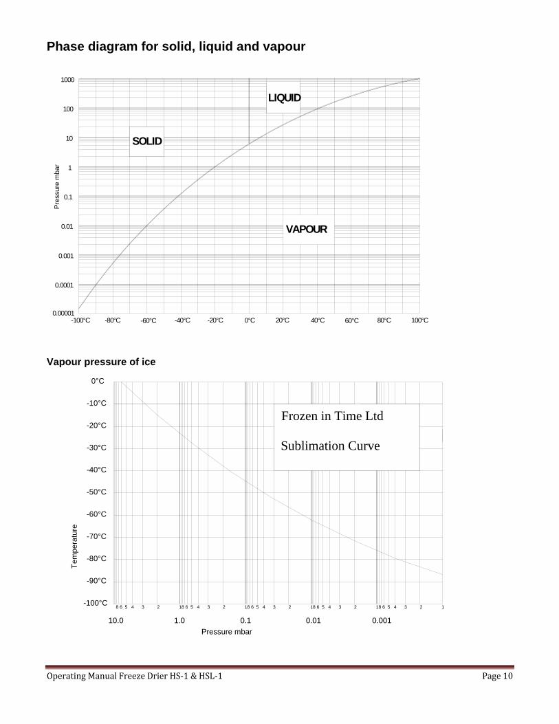
The principle of sublimation is briefly explained using the phase diagram of solid liquid and vapour. If the pressure is higher than 6.1 mbar, water can exist in all three phases (solid, liquid, vapour) when the temperature is lowered or raised. At 6.1 mbar and 0ºC all three lines meet, this is called the triple point where all three phase can occur simultaneously. Below this point when the pressure is lower than 6.1 mbar, the ice is converted directly from a solid to a vapour on reaching the sublimation pressure curve.
The sublimation curve shows the vapour pressure of water as affected by temperature and pressure.
Operating Manual Freeze Drier HS‐1 & HSL‐1 Page 10
Phase diagram for solid, liquid and vapour
-100°C 0°C-20°C-40°C-60°C-80°C 20°C 40°C 60°C 80°C 100°C
1000
10
100
1
0.1
0.01
0.001
0.0001
0.00001
SOLID
LIQUID
VAPOUR
Pre
ssur
e m
bar
Vapour pressure of ice
0°C
-10°C
-20°C
-30°C
-40°C
-50°C
-60°C
-70°C
-80°C
-90°C
-100°C
1.010.0 0.1 0.01 0.001
8 6 5 4 3 2 1 8 6 5 4 3 2 1 8 6 5 4 3 2 1 8 6 5 4 3 2 1 8 6 5 4 3 2 1
Pressure mbar
Tem
pera
ture
Frozen in Time Ltd
Sublimation Curve

Operating Manual Freeze Drier HS‐1 & HSL‐1 Page 11
Shelves at -50°CAtmospheric pressure
Shelves at 30°C or higher0.3mbar vacuum or lower
Product Drying
Condenserchamberrefrigeration isswitched off
Condenser chambertemperature -55°C or-85°C
Condensed Ice
Isolation valve closedIsolation valve open
Product Freezing
Cross sectional diagram of the freeze driers chambers during Product freezing and during Product drying.
Product Freezing
The Isolation valve is closed and the product is frozen by the low temperature of the shelves.
Product drying
The condenser is frozen to its minimum temperature. As the temperature goes below approximately -30ºC the vacuum pump can be switched on. The isolation valve must be opened and the vacuum is created in both chambers. When the vacuum is sufficient the heating can be applied to the shelves. Sublimation will cause the products on the shelves to dry. Deposition will occur in the condenser chamber as the sublimated vapour re-freezes.

Operating Manual Freeze Drier HS‐1 & HSL‐1 Page 12
2.2. Freezing the product.
Product can be frozen directly on the shelves of the HS-1 & HSL-1. This is the usual option for product to be freeze dried in trays or vials. The product is placed on the shelves and the shelves are cooled down to the desired temperature. The freezing can be done in stages, at a controlled rate or just as quickly as possible.
2.3. Primary drying The condenser drops to its operating temperature. The isolation valve is open The vacuum pump is switched on.
The duration of the main drying phase depends mainly on: • the layer thickness of the product, • the solid content of the product, • the heat supplied to the product during the drying process, • the vacuum pressure inside the drying chamber during the drying process. With increasing pressure the rate of sublimation rises as long as it stays below the vapour pressure of the product. This is because at higher pressures the heat energy reaches the sublimation front of the ice core sooner. Therefore the drying period is shortened. The water vapor generated during the main drying phase is not intended to be removed by the vacuum pump. It is to be collected by the ice condenser. The purpose of the vacuum pump is to lower the partial pressure of the non-condensable gases so that the water vapor can be transported from the product to the ice condenser. However, small quantities of water vapor will be removed by the vacuum pump. The vacuum pump is equipped with a gas ballast valve that when open, removes traces of condensable vapors from the pump. For this reason the gas ballast valve can be open during the main primary phase. The gas ballast valve is not required for secondary drying and closing it will help achieve a lower level of vacuum. During primary drying the moisture is removed by sublimation and during secondary drying the bound moisture is removed by desorption. The recommended vacuum pump should reach with open gas ballast valve, a vacuum level lower than the relevant water vapour pressure. Shelf temperatures can be raised in stages, at a controlled rate or set to maximum for fastest heat transfer. The heat input must of course not be enough to damage or melt the product. Too much heat will increase the amount of vapours to a point where the vacuum level diminishes to above the eutectic point of the product.
Operating Manual Freeze Drier HS‐1 & HSL‐1 Page 13
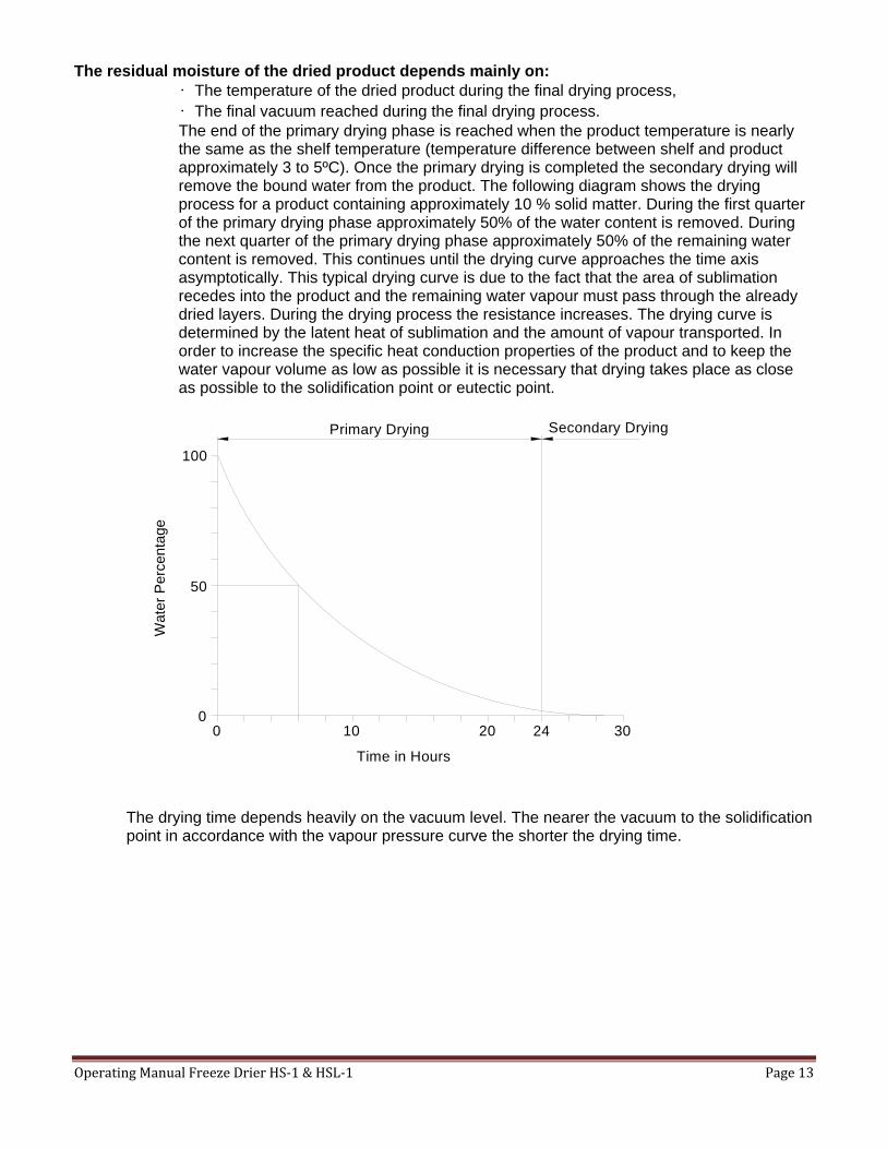
The residual moisture of the dried product depends mainly on: • The temperature of the dried product during the final drying process, • The final vacuum reached during the final drying process. The end of the primary drying phase is reached when the product temperature is nearly the same as the shelf temperature (temperature difference between shelf and product approximately 3 to 5ºC). Once the primary drying is completed the secondary drying will remove the bound water from the product. The following diagram shows the drying process for a product containing approximately 10 % solid matter. During the first quarter of the primary drying phase approximately 50% of the water content is removed. During the next quarter of the primary drying phase approximately 50% of the remaining water content is removed. This continues until the drying curve approaches the time axis asymptotically. This typical drying curve is due to the fact that the area of sublimation recedes into the product and the remaining water vapour must pass through the already dried layers. During the drying process the resistance increases. The drying curve is determined by the latent heat of sublimation and the amount of vapour transported. In order to increase the specific heat conduction properties of the product and to keep the water vapour volume as low as possible it is necessary that drying takes place as close as possible to the solidification point or eutectic point.
Primary Drying Secondary Drying
Time in Hours
Wat
er P
erce
ntag
e
00
10 20 24 30
50
100
The drying time depends heavily on the vacuum level. The nearer the vacuum to the solidification point in accordance with the vapour pressure curve the shorter the drying time.

Operating Manual Freeze Drier HS‐1 & HSL‐1 Page 14
Facts regarding ice in a vacuum:
1.0 gram of ice at; 1.0 mbar assumes a volume of 1 m³ vapour 0.1 mbar assumes a volume of 10 m³ vapour 0.01 mbar assumes a volume of 100 m³ vapour
Heat supply during drying The required heat supply to the product to be dried takes place by; Conduction through contact in the drying chamber Mild conduction through low pressure vapour Radiant heat energy.
Affects of freeze drying of a product in a dish
R e c e d in g ic e c o re
P ro d u c t T ra y
C o n ta c t h e a t tra n s fe r S h e lf
S u b lim a tio nF ro n t
V a p o r iz a t io nR a d ia n t h e a t
3 0 °C
R a d ia n t h e a t
Heat transfer takes place via the heated shelves by direct contact with the bottom of the tray. At the beginning of sublimation the transfer of heat is very effective from the wall of the tray to the frozen product. However, soon an area develops which is ice-free, porous, dried and has an insulating effect between the wall of the tray and the product. This slows down the heat energy transfer available to the ice core. The porous dried layer enables the passage of vapour from the ice core. If it is restricted the temperature will increase and ice core will thaw rather than sublimate. This applies especially to inhomogeneous products and to great layer thicknesses. During this drying phase it is important to regulate the heat supply and control temperature and pressure precisely.
2.4. Secondary drying The final pressure in the drying chamber depends on the ice condenser temperature according to the vapor pressure curve above ice : e. g. 1.030 mbar correspond to -20°C
0.370 mbar correspond to -30°C 0.120 mbar correspond to -40°C 0.040 mbar correspond to -50°C 0.01 mbar correspond to -60°C
The unit is in operating condition if the temperature of the ice condenser is lower than -50°C and the pressure is lower than 0.12 mbar. The final pressure measured when there is no product in the unit and its corresponding ice temperature is determined by the warmest ice surface in the condenser chamber.

Operating Manual Freeze Drier HS‐1 & HSL‐1 Page 15
2.5. Pressure rise test The pressure rise test is a good way to confirm that there is no more vaporizing ice in the product. In the automatic cycle, parameters set on the engineering screen of the control system will be followed. It can also be performed manually by the operator. When the secondary dying stage is considered to be finished, a pressure rise test will ensure it is. The shelve temperatures and the vacuum levels will still be in secondary drying conditions. The isolation valve is closed and the operator will watch to see the rate at which the vacuum level in the product chamber increases. The vacuum level will rise even with dry product, however the rate at which it rises when ice is still vaporizing is much greater. The operator must perform tests to become familiar with these rates of pressure rise.
2.6. Air admittance After the vials have been closed the vacuum in the chamber must be released by admitting air. Air will enter through the air admittance valve until the pressure is equalized and the door will release. This may take a few minutes.
2.7. Defrosting Defrosting of the ice condenser is carried out manually. First the operator must release the vacuum in the condenser chamber and remove the door. A suitable collecting vessel should be positioned under the door and drip deflector. Then defrost should be pressed. The LED will light up. If it does not make sure that the condenser refrigeration is not switched on. The Ice will melt and drain out. Defrost temperature is adjustable on the control panel. Press the down arrow once and the HI LED will light up. While this is lit scroll up or down to select a temperature. The default is 30°C.
Operating Manual Freeze Drier HS‐1 & HSL‐1 Page 16
3. Installation and Commissioning of the Unit 3.1. Site of installation In order to ensure the air circulation of the heat exchanger, do not place items behind the unit that could restrict air flow. The ambient temperature should be between approximately +5°C and +30°C. The refrigeration compressor of the freeze dryer is air-cooled. Sufficient air circulation must be ensured. A distance of at least 20cm to the wall should be kept. The unit should not be positioned near radiators or heat sources. In the case of insufficient air circulation or too high ambient temperatures, the temperature and the pressure in the refrigerating system will increase. If the maximum permissible operating pressure is exceeded, this may cause the refrigeration unit to switch off.
3.2. Mains power The operating voltage on the name plate must correspond to the local supply voltage. Frozen in Time freeze dryers are units of safety class I. The HS-1 & HSL-1 requires a single phase power supply 240 Volts. The freeze dryer must be on a circuit protected with a 16 Amp fuse or circuit breaker.
3.3. Air admittance Filtered air can be admitted into the product chamber. If an inert gas is needed such as nitrogen then a supply of this is required usually a gas cylinder. Take care not to over pressure the system.
3.4. Draining the condensate The condenser door must be removed and a suitable collecting vessel positioned before defrost is activated.
3.5. Vacuum pump exhaust gases The oil mist from the vacuum pump is normally trapped in an exhaust filter. If this is not the case, the oil mist has to be discharged ouside. A hose can be connected to the exhaust flange of the vacuum pump that leads into the open air or a vent. During installation of the pipe special care must be taken that condensate cannot flow back into the pump.

Operating Manual Freeze Drier HS‐1 & HSL‐1 Page 17
4. Operating the HS-1 & HSL-1
4.1 Loading Trays 4.1.1. Vial trays The vial trays are bottomless to allow direct thermal contact between vial and shelf. The vials are loaded onto the shelf with the use of a vial loader. The vial loader is then slid out and all the vials are kept in place within the vial locator. The vial loader slides from underneath the vials. When the product is to be unloaded the vial loader is slid back under the vials so they are supported. The vials, vial locator and vial loader can be removed as one.
Vial loader
Vial locator
Shelf
Vials with open caps
Vial loader
Vial locator
Shelf
Vials with closed caps
The vials being left on theshelf by the vial locator asthe vial loader is removed.
The vials are now beingscooped up by the vialloader.
There are 6 usable shelves and each shelf holds 2 shelf locators. The vial locators can hold various vial diameters. Shelf spacers can be removed and replaced with the correct size to suit any vial height. 4.1.2. Bulk trays Bulk trays can simply slide onto the shelves. Trays can be supplied in various sizes to suit the application.

Operating Manual Freeze Drier HS‐1 & HSL‐1 Page 18
4.2. Vacuum Pump The vacuum pump fitted to the HS-1 & HSL-1 has a 200l/min displacement. The pump can be activated by the control panel. It also has a rocker switch on the motor which isolates the pump from the freeze drier. This should always be on for normal operation. There is an interlock that prevent the vacuum pump from starting in ways that could cause problems. The condenser must be below -30°C before the vacuum pump will start. This can be overridden by pressing and holding the vacuum pump button down for a few seconds until you here a beeping sound. This override is not intended for normal operation, just testing purposes. The vacuum pump oil should be changed when the pump is warm. The oil level should be visible in the sight glass. The intervals for changing the oil will depend upon the products being freeze dried. With the -80ºC condenser chamber version it will offer better pump protection than the -55 ºC The condenser chamber temperature must be lower than the temperature corresponding to the vapour pressure that the product is going to freeze dried at. In the case of water vapour the following is a good guide:
1.030 mbar correspond to -30°C 0.370 mbar correspond to -40°C 0.120 mbar correspond to -50°C 0.040 mbar correspond to -60°C 0.01 mbar correspond to -70°C 0.003 mbar correspond to -80°C
If the product contains large quantities of chemicals that are more volatile than water then lower temperatures in relation to vacuum levels are required. An oil mist filter should be fitted to the exhaust port of the vacuum pump. For extra information on the pump please see the separate operating manual.
Operating Manual Freeze Drier HS‐1 & HSL‐1 Page 19
4.3. Isolation valve The Isolation valve is manual and is to the left hand side of the condenser chamber door.
4.4. Air/inert gas admittance valve Either filtered air or an inert gas can be admitted into the system. This is located on the inlet to the vacuum pump.
4.5. Condenser draining The condenser can be drained out of the condenser door into a suitable container. Before pressing defrost the door should be removed so there is free drainage as the ice melts.
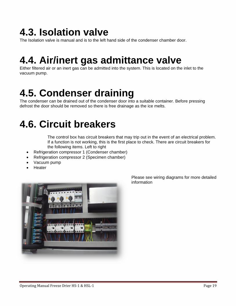
4.6. Circuit breakers The control box has circuit breakers that may trip out in the event of an electrical problem. If a function is not working, this is the first place to check. There are circuit breakers for the following items. Left to right
• Refrigeration compressor 1 (Condenser chamber) • Refrigeration compressor 2 (Specimen chamber) • Vacuum pump • Heater
Please see wiring diagrams for more detailed information

Operating Manual Freeze Drier HS‐1 & HSL‐1 Page 20
5. The Control System
5.1 LED`s Indicator LED`s will show which functions are active on the freeze drier. If a button is pressed and the LED does not illuminate then the function has not been activated due to an interlock. An interlock will block incorrect functions from being selected. When temperatures are being selected the LED will indicate which temperature is being displayed.
5.2 Condenser Chamber Refrigeration
When the condenser chamber button is pressed, the condenser refrigeration will start, the LED will light up and the condenser chamber temperature will initially be displayed. When it is switched off the LED will switch off however the refrigeration system will continue to run for a few minutes. This delay in switching off the refrigeration will enable the compressor to evacuate the suction pipes.
5.3 Specimen Chamber Refrigeration
When the specimen chamber button is pressed, the condenser refrigeration will start, the LED will light up and the specimen chamber temperature will initially be displayed. When it is switched off the LED will switch off however the refrigeration system will continue to run for a few minutes. This delay in switching off the refrigeration will enable the compressor to evacuate the suction pipes. Pressing the downward pointing temperature control button sets the specimen chamber target temperature. One touch of this button displays the cut out temperature of the chamber. To set this temperature, you can adjust with the up or down pointing buttons. This set point is also used for controlling the heater temperature.

Operating Manual Freeze Drier HS‐1 & HSL‐1 Page 21
5.4 Defrost The defrost may only be selected when all other buttons have been switched off. The defrost will run for a one hour to melt the ice, it will then switch off. If any ice remains then it can be switched on again and it will run for another hour. This ensures that defrost does not get forgotten about and left to run for excessive amounts of time. Pressing the upward pointing temperature control button sets the defrost target temperature. One touch of this button displays the cut out temperature of the defrost condenser coils. To set this temperature, you can adjust with the up or down pointing buttons.
5.5 Heater The heater function refers to the specimen chamber heater. Switching this on will heat up the specimen chamber. This function is subject to an interlock. It can only be activated when the vacuum pump is running. (the vacuum pump can only be activated when the condenser chamber is below -30°C) When it is activated the LED will illuminate. The heater output itself is controlled by a temperature set point and a vacuum control set point.
Setting the heater temperature uses the same set point as the specimen chamber refrigeration. Pressing the downward pointing temperature control button sets the specimen chamber target temperature. One touch of this button displays the cut out temperature of the chamber. To set this temperature, you can adjust with the up or down pointing buttons.
When the vacuum is above a settable level the heater will not produce heat. The reason for this is that when freeze drying, it is necessary not to go above a certain vacuum level.
For example if you do not want the vacuum to go above 0.4 mbar then you would set it at 0.4 If the level went above this the heater would not produce heat. This would cause the sublimation to slow down and the vacuum level would recover.
This vacuum control set point is settable between 0.1 mbar and 1.0 mbar. If vacuum control above 1.0 mbar is required or if heaters are to be tested with no vacuum level at all then the set point needs to be turned off.
To change the set point press and hold the vacuum sensor selector button for specimen chamber until the displays change. The display on the right will say either Off or a number between 1.0 and 0.1. Scroll up with the arrow keys until you reach OFF and then wait until it returns back to normal mode. It takes a few seconds.
Operating Manual Freeze Drier HS‐1 & HSL‐1 Page 22
5.6 Vacuum Pump
The condenser chamber refrigeration must be running before the vacuum pump can be activated. The Vacuum pump can only be activated when the condenser temperature is below -30°C. When the vacuum pump is running the indicator light will be illuminated.
5.7 Vacuum Display
The display is in Millibars. It shows the level of vacuum in the system and this will vary throughout the drying cycle. This is because the products are giving off water vapour and gases that raise the vacuum level. Near the end of the cycle the pressure will be lower. The display will read OFF while the vacuum pump is switched off. When the vacuum pump is switched on, the display will read ON. When the pressure has dropped to below 500 Millibars (half of atmospheric pressure) it will start to register the pressure.
5.8 Temperature Display
The temperature is displayed in °C. The display will switched between the condenser chamber, the specimen chamber and the 4 mobile probes.
To select the condenser chamber temperature press the oval button below the condenser chamber refrigeration activation button.
To select the specimen chamber temperature press the oval button below the specimen chamber refrigeration activation button.
To select a probe temperature press the round buttons labeled 1 to 4. When temperatures are being selected the LED will indicate which temperature is being displayed. Temperature probes 1 to 4 are the loose probes in the specimen chamber that can be inserted into samples chosen in different areas of the specimen chamber.

Operating Manual Freeze Drier HS‐1 & HSL‐1 Page 23
6. Troubleshooting 6.1. Power failure The freeze drier will resume its program or settings after a power failure. In the event of a power failure in the drying phase, the batch may become unusable. Whether the batch can be saved or not depends on the drying phase in which the product was in when the power failure occurred. If power returns within a few minutes then it is unlikely that any damage will have occurred. It is important to distinguish between the primary drying phase and the secondary drying phase. The product is in the secondary drying phase if the residual moisture has reached approximately 5 %. Below this value, the product is generally not damaged by a power failure. If the product is in the primary drying phase, it is recommended that the product is refrozen. It is also advisable to defrost the condenser chamber at this point. If the product is considered to be still usable then freeze drying can restart.
6.2. Insufficient vacuum Is the vacuum pump is running? If not:
• Check that the pump motor switch is on • Check that the IEC connection lead is connected • Check that the vacuum pump circuit breaker has not switched off. • Check that the contactor is operating.
If the vacuum is sufficient on the condenser chamber but significantly worse on the specimen chamber: • Check that air admittance and inert gas valves are closed. • Check all vacuum connections on specimen chamber including door seal. Repair or replace. • Check for oil leakages from the shelf thermal fluid. Oily residue may collect in the chamber. • Check for water from cleaning or spilled product residue, this may vaporize preventing vacuum. • Remove panels and listen for leaks after a vacuum evacuation has been tried.
If the vacuum cannot be achieved in the condenser chamber with the isolation valve closed: • Check all vacuum connections on condenser chamber including door seal. Repair or replace. • Check the condition of the isolation valve sealing surface. Glass pieces from broken vials can slit
the rubber seal. If there is a doubt about this coat in vacuum pump oil or vacuum grease and test to see if there has been an improvement in the vacuum level.
• Check that there is no suction on the air inlet. This would indicate a leaking valve. • Check the vacuum pump is pulling an adequate vacuum, test with a separate vacuum sensor. • Check that the isolation valve is sealing by opening it and pulling a vacuum on the product
chamber as well, eliminating the seal of the valve. If the vacuum pump cannot achieve a sufficient vacuum then replace it or get it repaired. 6.3. Insufficient cooling of the condenser chamber If the condenser chamber is not reaching the relevant temperature -55ºC or -85ºC (Please allow 15% for high load conditions)
• Check to see if there is liquid flow in the refrigeration sight glass. Contact the manufacturer, supplier or a local refrigeration engineer.
• Check the circuit breakers for compressor 1, compressor 2 and fans. • Check that the contactors are operating. • Check the overview screen to ensure that refrigeration and condenser cooling are operating.
6.4. Insufficient defrosting of the condenser chamber If defrost is not heating up.
• Check the circuit breaker for defrost
Operating Manual Freeze Drier HS‐1 & HSL‐1 Page 24
• Check that the contactor is operating. • Ensure that defrost LED is activated. • Check that temperature control is not controlled by a sensor that is malfunctioning and reading an
incorrectly high temperature.
6.5. Insufficient cooling of the shelves If the shelves are not reaching low set points or relevant temperature -45ºC or -60ºC
• Check to see if there is liquid flow in the refrigeration sight glass. Contact the manufacturer, supplier or a local refrigeration engineer
• Check the circuit breakers for compressor 1, compressor 2, fans and circulation pump • Check that all the contactors are operating. • Check the overview screen to ensure that refrigeration, shelf cooling and circulation pump are
operating. • Check that temperature control is not controlled by a sensor that is malfunctioning and reading an
incorrectly low temperature.
6.6. Insufficient heating of the shelves If the shelves are not reaching high set points or the relevant temperatures 60ºC to 80ºC.
• Check the circuit breaker for heater and circulation pump. • Check that all the contactors are operating. • Ensure that heater and circulation pump are activated. • Check that shelf temperature control is not controlled by a sensor that is malfunctioning and
reading an incorrectly high temperature. 6.8. Doors will not seal under vacuum If the doors will not seal under vacuum
• Check that the vacuum pump is running • Close the isolation valve and check that the condenser door is sealing • Check that the air admittance valve is closed. • Clamp the product chamber door and check that it is pushed up against its seal all around. • Open the isolation valve and release the door clamps.
Does the door still open? 6.9. Incorrect probe temperature Incorrect probe temperatures can be due to
• Unplugged probes • Broken thermocouples • Thermocouples with loose connections
6.10. Trays are distorting Large trays can have a tendency to distort with high and low temperature. Avoid using large trays where possible. When they are cold they tend to twist and when they are warm they tend to bow. The shelf to tray contact becomes less and freeze drying rates are reduced.
7. Maintenance

Operating Manual Freeze Drier HS‐1 & HSL‐1 Page 25
7.1. Condenser chamber Before each start-up, ensure that condenser chamber is drained.
7.2. Heat exchanger The refrigeration heat exchanger is used to cool the refrigerant compressed by the refrigeration unit. The heat exchangers are located on each side of the unit and should be kept free of dust or dirt residues. The heat exchanger can be cleaned by brushing, using a vacuum cleaner from the outside or by using compressed air from inside of the unit. Excessive build up on the heat exchanger leads to a decrease in performance and may cause a failure of the unit.
7.4. Rubber seals Special attention must be paid to the rubber seals. If the seals are dirty, they must be removed, cleaned and slightly greased with vacuum grease. If they show signs of cracking they must be replaced.
7.5. Vacuum pump Clean up any oil spills on or around the freeze drier from oil changes. For the maintenance of the vacuum pump, please refer to the separate operating manual. Additionally: The oil level of the vacuum pump must be regularly checked at the sight glass (in case of continuous operation at least once a day). Top up oil to the required level via the oil inlet. Due to possible operation with gas ballast, oil consumption cannot be avoided. For topping-up see the operating manual of the pump. The oil change should always be carried out with warm pump.
7.6. Exhaust filter The exhaust filter should be replaced if it becomes saturated. Where possible there should still be a pipe after the exhaust filter leading into open air. Take care that the condensate in the filter does not rise too high.
7.7. Cleaning freeze dryer
Operating Manual Freeze Drier HS‐1 & HSL‐1 Page 26
Use soapy water or other water-soluble, mild cleaning agents to clean the freeze dryer. Avoid corrosive and aggressive substances. Do not use alkaline solutions, solvents or agents with abrasive particles. Remove product residues from the ice condenser chamber using a cloth. It is recommended to open the doors of the freeze drier when it is not in use so that moisture can evaporate. If there is the risk of toxic, radioactive or pathogenic contamination, special safety measures must be considered and adhered to.
7.8. Checks by the operator The operator has to ensure the important parts of the freeze dryer and those necessary for safety are not damaged. This especially refers to:
• Doors and hinges • Seals • Oil level of vacuum pump • Heat exchangers • Exhaust filter