manualslib - makes it easy to find manuals online! · dv4td euro/3 euro/4 family citroèn c2...
TRANSCRIPT

20032003 CAR 050016
AC.QCAV/MTD
Méthodes Techniques Documentation
� ’’The intellectual property rights relating to the technical information contained in this document belongexclusively to the manufacturer. Reproduction, translation or distribution in whole or in part withoutprior written authorisation from the manufacturer is forbidden.‘‘
PR
IVA
TE
CA
RS
«The technical information contained in this document is intended for the exclusive use of the trained personnel of themotor vehicle repair trade. In some instances, this information could concern the security and safety of the vehicle. Theinformation is to be used by the professional vehicle repairers for whom it is intended and they alone would assume fullresponsibility to the exclusion of that of the manufacturer».«The technical information appearing in this brochure is subject to updating as the characteristics of each model in therange evolve. Motor vehicle repairers are invited to contact the CITROËN network periodically for further information andto obtain any possible updates».
Downloaded from www.Manualslib.com manuals search engine

PRESENTATION
THIS HANDBOOK summarises the specifications, adjustments, checks and special features of the CITROEN C2.
The handbook is divided into nine groups representing the main functions :
GENERAL - ENGINE - INJECTION - IGNITION - CLUTCH, GEARBOX, DRIVESHAFTS - AXLES, SUSPENSION, STEERING - BRAKES - ELECTRICALAIR CONDITIONING.
Downloaded from www.Manualslib.com manuals search engine
GE
NE
RA
L
1
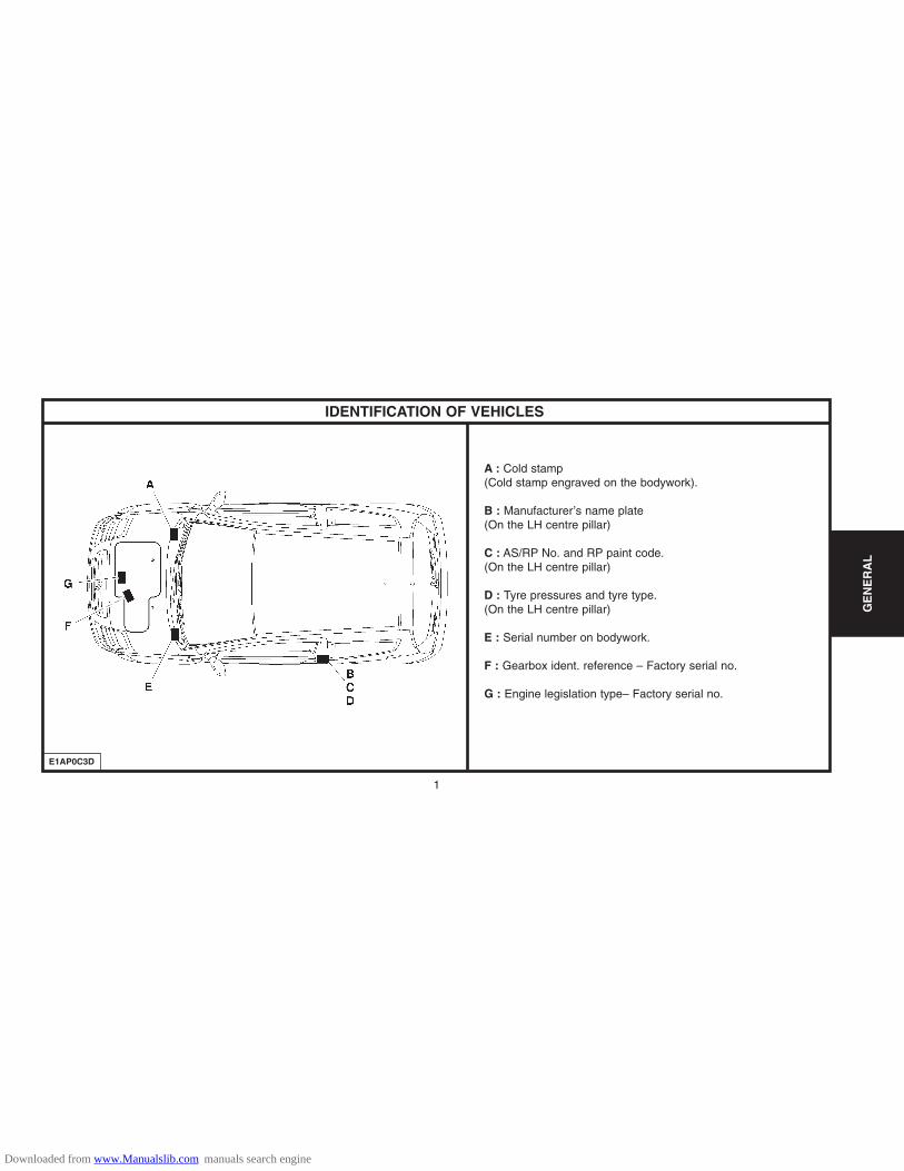
IDENTIFICATION OF VEHICLES
E1AP0C3D
A : Cold stamp (Cold stamp engraved on the bodywork).
B : Manufacturer’s name plate(On the LH centre pillar)
C : AS/RP No. and RP paint code.(On the LH centre pillar)
D : Tyre pressures and tyre type.(On the LH centre pillar)
E : Serial number on bodywork.
F : Gearbox ident. reference – Factory serial no.
G : Engine legislation type– Factory serial no.
GE
NE
RA
L
Downloaded from www.Manualslib.com manuals search engine
2
GE
NE
RA
L
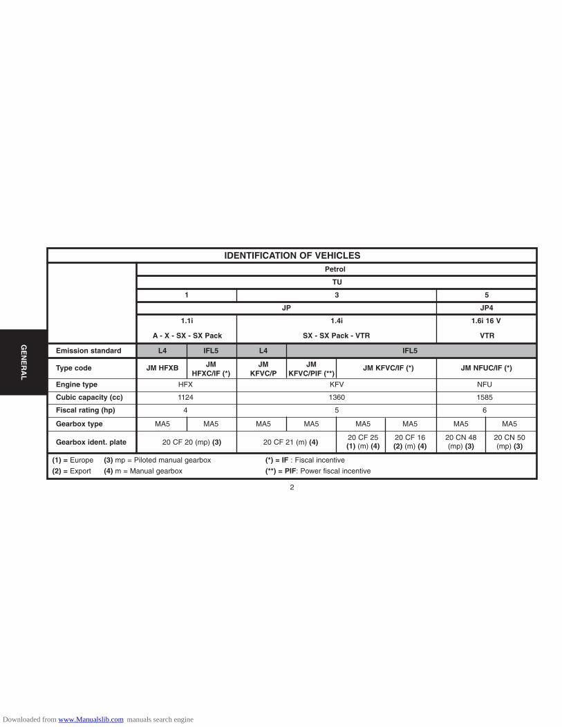
Emission standard L4 IFL5 L4 IFL5
Type code JM HFXB JM JM JM JM KFVC/IF (*) JM NFUC/IF (*)HFXC/IF (*) KFVC/P KFVC/PIF (**)
Engine type HFX KFV NFU
Cubic capacity (cc) 1124 1360 1585
Fiscal rating (hp) 4 5 6
Gearbox type MA5 MA5 MA5 MA5 MA5 MA5 MA5 MA5
Gearbox ident. plate 20 CF 20 (mp) (3) 20 CF 21 (m) (4)20 CF 25 20 CF 16 20 CN 48 20 CN 50(1) (m) (4) (2) (m) (4) (mp) (3) (mp) (3)
IDENTIFICATION OF VEHICLESPetrol
TU
1 3 5
JP4JP
1.1i 1.4i 1.6i 16 V
A - X - SX - SX Pack SX - SX Pack - VTR VTR
(1) = Europe
(2) = Export
(3) mp = Piloted manual gearbox
(4) m = Manual gearbox
(*) = IF : Fiscal incentive
(**) = PIF: Power fiscal incentive
Downloaded from www.Manualslib.com manuals search engine
3
GE
NE
RA
L
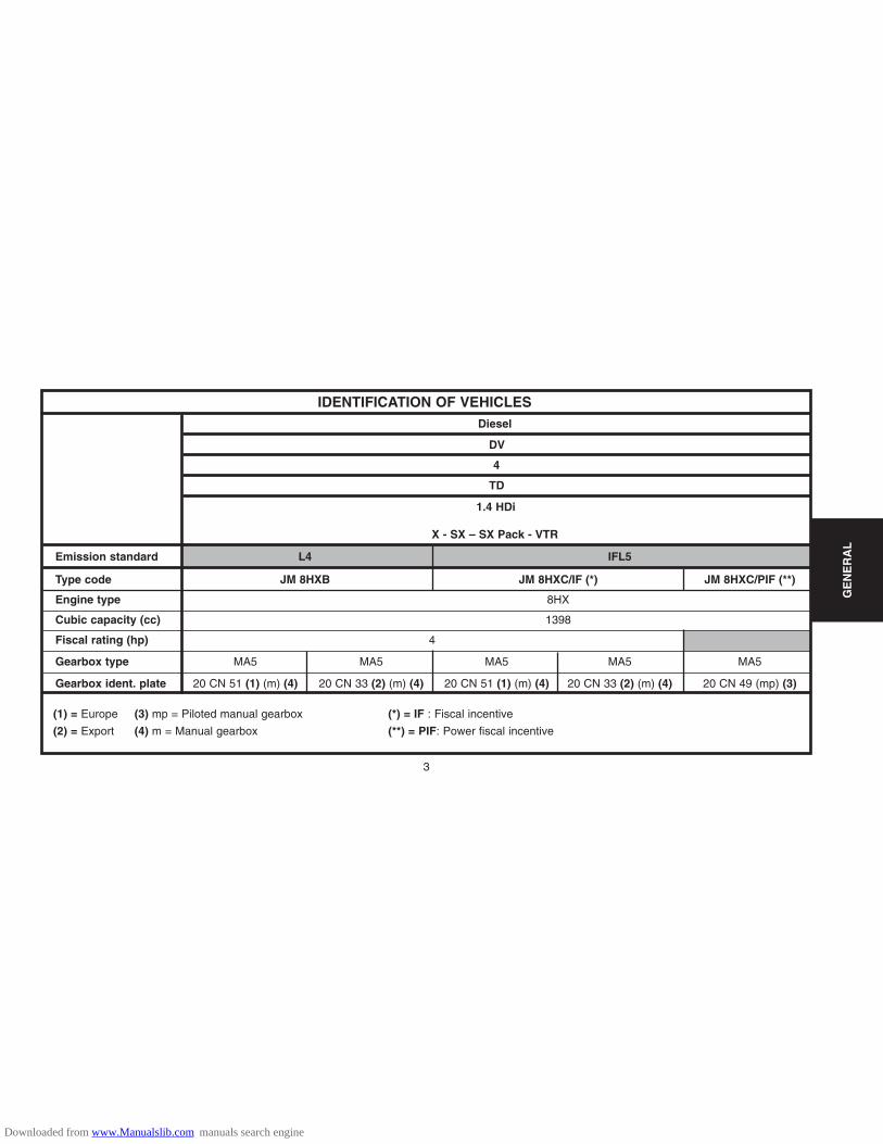
IDENTIFICATION OF VEHICLESDiesel
DV
4
TD
1.4 HDi
X - SX – SX Pack - VTR
Emission standard L4 IFL5
Type code JM 8HXB JM 8HXC/IF (*) JM 8HXC/PIF (**)
Engine type 8HX
Cubic capacity (cc) 1398
Fiscal rating (hp) 4
Gearbox type MA5 MA5 MA5 MA5 MA5
Gearbox ident. plate 20 CN 51 (1) (m) (4) 20 CN 33 (2) (m) (4) 20 CN 51 (1) (m) (4) 20 CN 33 (2) (m) (4) 20 CN 49 (mp) (3)
(1) = Europe
(2) = Export
(3) mp = Piloted manual gearbox
(4) m = Manual gearbox
(*) = IF : Fiscal incentive
(**) = PIF: Power fiscal incentive
Downloaded from www.Manualslib.com manuals search engine

4
GE
NE
RA
L
IDENTIFICATION OF VEHICLESManufacturer’s plate.
E1AP09JC
The manufacturer’s plate carries the following information :
(a) Type approval number (*).
(b) Type serial number (VIN).
(c) Gross vehicle weight (*).
(d) Gross vehicle weight (*).
(e) Maximum weight on front axle (*).
(f) Maximum weight on rear axle (*).
(g) Manufacturer identification.
(*) = according to marketing country.
Downloaded from www.Manualslib.com manuals search engine
5
GE
NE
RA
L
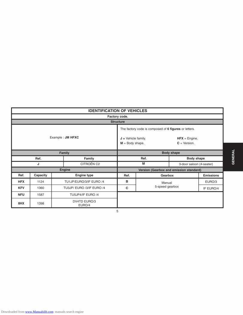
IDENTIFICATION OF VEHICLESFactory code.
Structure
The factory code is composed of 6 figures or letters.
J = Vehicle family. HFX = Engine.
M = Body shape. C = Version.
Body shape
Ref. Body shape
3-door saloon (4-seater)M
Version (Gearbox and emission standard)
Ref. Gearbox
Manual 5-speed gearbox
Emissions
EURO/3
IF EURO/4
B
C
Example : JM HFXC
Family
Ref.
J
Engine
Ref.
HFX
KFV
NFU
8HX
Capacity
1124
1360
1587
1398
Engine type
TU1JP/EURO/3/IF EURO /4
TU3JP/ EURO /3/IF EURO /4
TU5JP4/IF EURO /4
DV4TD EURO/3EURO/4
Family
CITROËN C2
Downloaded from www.Manualslib.com manuals search engine

6
GE
NE
RA
L
GENERAL SPECIFICATION : DIMENSIONS
E1AP0C4D
Exterior dimensions
Downloaded from www.Manualslib.com manuals search engine

Exterior dimensions (mm)
7
GE
NE
RA
L
GENERAL SPECIFICATION : DIMENSIONS
Interior dimensions and volumes (mm)
Vehicles All typesWheelbase A 2315Length overall B 3666Front overhang C 760Rear overhang D 591Rear track * E 1435Front track * F 1438Width overall G 1660Height overall * H 1462
(*) = Vehicle in running order (vehicle empty, levels topped up).
(*) = Boot floor with adjustable configuration.
Elbow width, front 1406Elbow width, rear 1402Height of boot below parcel shelf 585Minimum floor width 1040Depth of bootspace at floor level 660Volume of boot below parcel shelf (dm3) 305Volume in dm3 of boot below Moduboard (*) 282
Downloaded from www.Manualslib.com manuals search engine

8
GE
NE
RA
L
Versions 1.1i 1 4i 1.6i 16V 1.4 HDi
Engine type HFX KFV NFU 8HX
Gearbox type MA
Payload 485 465 467 479
Weight empty Without options 1053 1080 1133 1097
in running order With all options 1138 1147 1200 1177
Gross vehicle weight 1463 1470 1525 1501
Gross train weight 2113 2370 2425 2401
Maximum trailer weight without brakes 926 1174 1176 1175
Maximum trailer weight with brakes 526 540 566 548
Incline 12% 38 47 48 47
Maximum nose weight 60 60 60 60
GENERAL SPECIFICATION : WEIGHTS
Petrol Diesel
Downloaded from www.Manualslib.com manuals search engine
9
GE
NE
RA
L
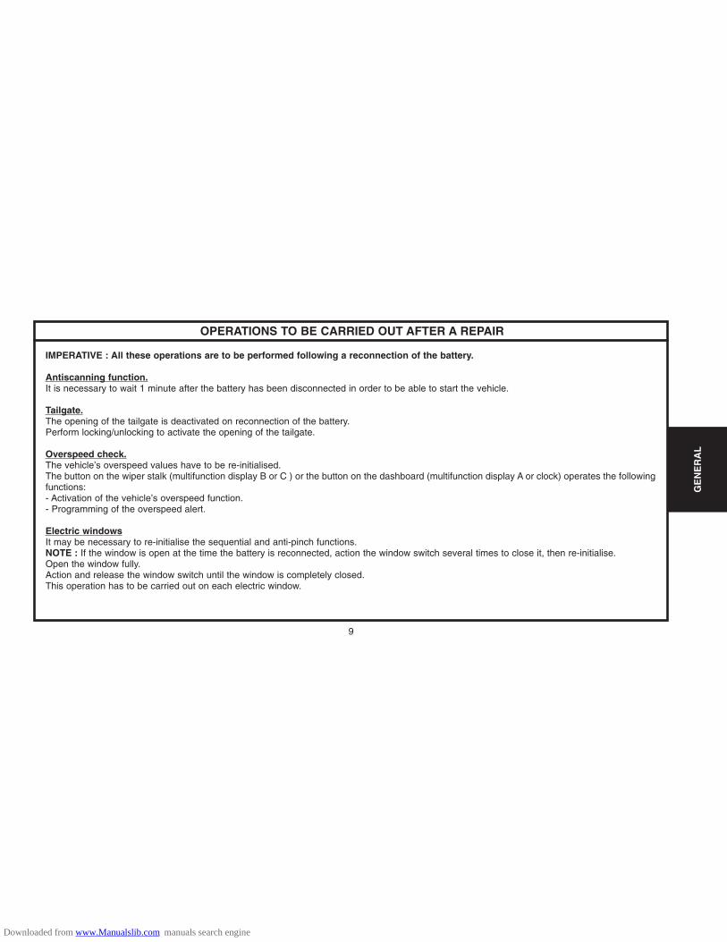
OPERATIONS TO BE CARRIED OUT AFTER A REPAIR
IMPERATIVE : All these operations are to be performed following a reconnection of the battery.
Antiscanning function.It is necessary to wait 1 minute after the battery has been disconnected in order to be able to start the vehicle.
Tailgate.The opening of the tailgate is deactivated on reconnection of the battery.Perform locking/unlocking to activate the opening of the tailgate.
Overspeed check.The vehicle’s overspeed values have to be re-initialised.The button on the wiper stalk (multifunction display B or C ) or the button on the dashboard (multifunction display A or clock) operates the followingfunctions: - Activation of the vehicle’s overspeed function.- Programming of the overspeed alert.
Electric windowsIt may be necessary to re-initialise the sequential and anti-pinch functions.NOTE : If the window is open at the time the battery is reconnected, action the window switch several times to close it, then re-initialise.Open the window fully.Action and release the window switch until the window is completely closed.This operation has to be carried out on each electric window.
Downloaded from www.Manualslib.com manuals search engine

10
GE
NE
RA
L
OPERATIONS TO BE CARRIED OUT AFTER A REPAIR
Sun roof.The anti-pinch function has to be re-initialised.Place the sun roof switch in the maximum tilt position.Keep the sun roof switch pressed until the sun roof ceases its movement.Release the sun roof switch within 5 seconds.Keep the sun roof switch pressed until the end of the sun roof opening sequence.
Multifunction screen.It is necessary to adjust the date, time and outside temperature.Adjust the display language of the multifunction screen if necessary.NOTE : The default display language of the multifunction screen is French.
Navigation.Warning, the vehicle has to be in the open air (on switching on the ignition, the ECU searches for satellites).Vehicle location is only effective after some ten minutes.Reprogramme the customer parameters.
Radio.Reprogramme the radio stations.
Radiotelephone RT3.Reprogramme the radio stations.
Downloaded from www.Manualslib.com manuals search engine

11
GE
NE
RA
L
GENERAL SPECIFICATION : TOWING THE VEHICLE
Front towing
Rear towing
WARNING : When the engine is not running,steering and braking are no longer power-assisted.
Towing eye
(1) Towing eye
The towing eye (1) is to be found in the vehicletoolkit located under one of the front seats.
E2AP029C E2AP02AC E2AP02BC
Downloaded from www.Manualslib.com manuals search engine
12
GE
NE
RA
L
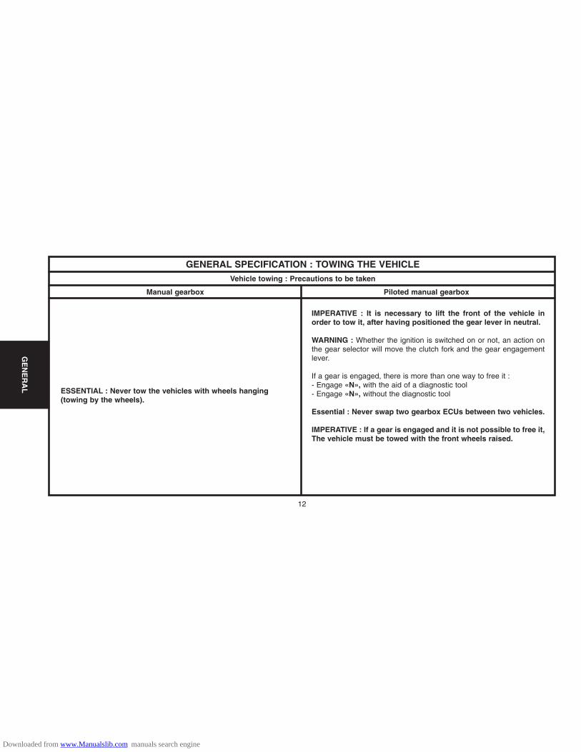
GENERAL SPECIFICATION : TOWING THE VEHICLEVehicle towing : Precautions to be taken
Manual gearbox Piloted manual gearbox
ESSENTIAL : Never tow the vehicles with wheels hanging(towing by the wheels).
IMPERATIVE : It is necessary to lift the front of the vehicle inorder to tow it, after having positioned the gear lever in neutral.
WARNING : Whether the ignition is switched on or not, an action onthe gear selector will move the clutch fork and the gear engagementlever.
If a gear is engaged, there is more than one way to free it : - Engage «N», with the aid of a diagnostic tool- Engage «N», without the diagnostic tool
Essential : Never swap two gearbox ECUs between two vehicles.
IMPERATIVE : If a gear is engaged and it is not possible to free it,The vehicle must be towed with the front wheels raised.
Downloaded from www.Manualslib.com manuals search engine

13
GENERAL SPECIFICATION : TOWING THE VEHICLE
GE
NE
RA
L
Vehicle towing : Precautions to be taken
Piloted manual gearbox
Engagement of «N», using a diagnostic tool.
Preliminary operation : - Battery voltage higher than 12 Volts.- Ignition switched on.- Connect the diagnostic tool to the vehicle’s diagnostic socket.
Using the menus of the diagnostic tool, select : - «DIAGNOSIS»- MA piloted manual gearbox.- Actuator tests.- Gearbox actuator test.- Gear engagement test.- N (Neutral).
NOTE : The letter «N» should appear on the instrument panel. If thisdoes not happen, see the following solution: - Engagement of «N», without using a diagnostic tool.
Engagement of «N», without a diagnostic tool.
In this configuration, the gearbox actuator is blocked, gear engaged.
IMPERATIVE : This recovery solution is to be used solely in a casewhere the methods for setting the gearbox actuators using thediagnostic tool have failed (destruction of the gearbox actuator)
Downloaded from www.Manualslib.com manuals search engine

14
GE
NE
RA
L
GENERAL SPECIFICATION : TOWING THE VEHICLEVehicle towing : Precautions to be taken
Piloted manual gearbox
Preliminary operations:
- Disconnect the battery negative terminal.
- Remove the air filter.
- Position a 22 mm flat spanner.
- Lift the gear engagement lever as far as possible (in the direction ofthe arrow); use a screwdriver to hold it in this position.
- Turn the spanner until the axis of the gear engagement lever (A) is atright angles to the axis (B).
- When this position is attained, position «N» is engaged.
Moving the vehicle.
IMPERATIVE : Never be towed with the ignition switched on.
Never attempt to push-start the vehicle (impossible with a piloted manualgearbox).
B2CP3L8D
Downloaded from www.Manualslib.com manuals search engine

15
GE
NE
RA
L
Lifting and supporting the vehicle Side liftingFront lifting
Front of the vehicle.
The authorised lifting points at the front of the vehicle are on the rear fixing bolts ofthe subframe at «a».For front lifting, take weight at the two lifting points at «a», using a crossbeam equippedwith blocks.For front lifting from the side, take weight at the lifting point at «a».
ESSENTIAL : Never attempt to lift by the frontpanel mountings.
Side liftingAlways ensure the jack is correctly positioned at thelifting points.Do not place the axle stands under the jack contactlugs.
Lifting from the rear.IMPERATIVE : Do not lift the vehicle by the rear.Position of the axle stand.
B3CP07KC E2AP016C E2AP00GCE2AP018CE2AP017C
GENERAL SPECIFICATION: LIFTING AND SUPPORTING THE VEHICLE
Downloaded from www.Manualslib.com manuals search engine

16
GE
NE
RA
L
GENERAL SPECIFICATION: LIFTING AND SUPPORTING THE VEHICLELifting and supporting the vehicle (continued)
Lifting with the handle jack at the front
Lifting with the handle jack at the rear
Lifting on a two-column lift using the jack supports
Lift accessory with blocks on the jack supports
E2AP026C E2AP028D
E2AP025C E2AP027D
NOTE : The handle jack is specific to the vehicle, do not useit for any other purposes.
Downloaded from www.Manualslib.com manuals search engine

17
GE
NE
RA
L
CAPACITIES (in litres)
Draining method.
The oil capacities are defined according to the following methods.
1/ Vehicle on level surface (in high position, if equipped with hydropneumatic suspension).
2/ Engine warm (oil temperature 80°C).
3/ Draining of the oil sump + removal of the cartridge (duration of draining + dripping = 15 min).
4/ Refit plug + cartridge.
5/ Engine filling.
6/ Engine starting (allowing the cartridge to be filled).
7/ Engine stopped (stationary for 5 min).
ESSENTIAL : Systematically check the oil level using the oil dipstick.
Downloaded from www.Manualslib.com manuals search engine

18
GE
NE
RA
L
1.1i 1.4i 1.6i 16V 1.4 HDi
Engine type HFX KFV NFU 8HX
Drain by gravity : engine with filter change 3 3.25 3.75
Between Min. and Max. 1.5 1.8 9 RPO 9844)1.5 (RPO 9845 9)
MA5 5-speed gearbox 2
MA5 piloted 5-speed gearbox 2 ± 0.15
Braking circuit0.7 Litre version with front calipers Ø 48 / rear drums
0.8 Litre version with front calipers Ø 54 / rear discs
Cooling system 7 5.6
Fuel tank capacity 40 45
CAPACITIES (in litres)
Petrol
C2
Diesel
ESSENTIAL : Systematically check the oil level using the oil dipstick.
Downloaded from www.Manualslib.com manuals search engine
19
GE
NE
RA
L
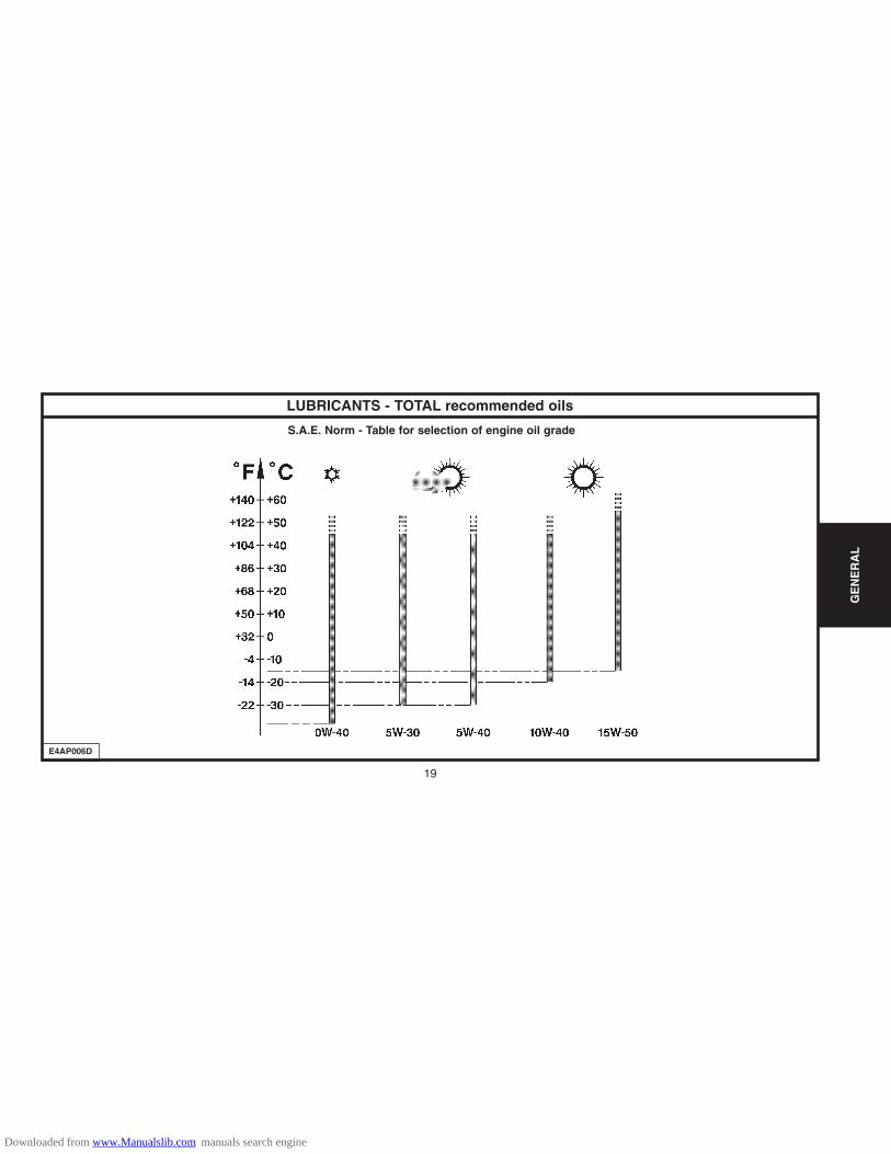
LUBRICANTS - TOTAL recommended oils
S.A.E. Norm - Table for selection of engine oil grade
E4AP006D
Downloaded from www.Manualslib.com manuals search engine

LUBRICANTS – TOTAL recommended oils
20
GE
NE
RA
L
Factory evolutions in 2001 model year
CITROËN engines are lubricated at the factory with TOTAL oil ofgrade S.A.E.5W-30.TOTAL oil of grade S.A.E.5W-30 allows improved fuel economies(approx 2.5%).
Features of CITROËN C5 :2.0 and 2.2 HDi engines have a particle filter.The maintenance interval for normal operationis 30,000 km (20,000 miles) for petrol engines.
WARNING : HDi engines are high technology engines whichimperatively require use of quality SYNTHETIC OILS : TOTALACTIVA or TOTAL QUARTZ 5W40.To maintain engine performances, all countries in Europeshould observe this requirement.
NOTE : Only PORTUGAL and GREECE may use 10W40 semi-synthetic oil.
ESSENTIAL : For all vehicles with a 30,000 km (20,000 miles)maintenance interval, use exclusively TOTAL ACTIVA/QUARTZ7000 or 9000 or any other oils offering identical specifications tothese.These oils offer specifications that are superior to those definedby norms ACEA A3/98 or API SJ.Failing this, it is essential to adhere to the maintenance pro-grammes covering severe operating conditions.
5W30 cannot be used in the following engines:XU10J4RS : XSARA VTS 2.0i 16V (3 doors).SOFIM : RELAY 2.8 D and 2.8 TD.1580 SPI : DISPATCH 1.6i.2.0 and 2.2 HDi engines equipped with particle filter.
WARNING : CITROËN engines prior to model year 2000 do nothave to be lubricated with oils adhering to the norms ACEA A1-98/B1-98 and API SJ/CF EC.
Downloaded from www.Manualslib.com manuals search engine

21
GE
NE
RA
L
LUBRICANTS – TOTAL recommended oils
Selection of engine oil grades recommended for climatic conditions in countries of distribution
ACEA NormsThe first letter corresponds to the type of engine concerned :
A : petrol and dual fuel petrol / LPG engines.B : diesel engines.
The figure following the first letter corresponds to the type of oil.1 : highly fluid oils, for reducing friction and lowering fuel
consumption.3 : high performance oils.
The number after that (96 or 98) corresponds to the year ofcreation of the norm.
NOTE : From 01/03/2000, all engine oils must comply with ACEA-98norms.
Example : ACEA A1-98 / B1-98 : Blended oils for all engines, permitting fueleconomy (complying with ACEA 98 norms).
API NormsThe first letter corresponds to the type of fuel used by the engine :
S : petrol and dual fuel petrol / LPG engines.C : diesel engines.
The second letter corresponds to the degree of evolution, in ascendingorder.Example : The norm SJ is more severe than the norm SH and corres-ponds to a higher level of performance.The adding of the letters EC indicates that the engine oil concerned isan oil which permits fuel economy.EC : Energy Conserving, reduction in fuel consumption.Examples : API SJ / CF : Blended oils for all engines.engines API CF / EC: Oils specifically for diesel engines, permitting fueleconomy.API SJ / CF / EC : Blended oils for all engines, permetting fuel economy.
Downloaded from www.Manualslib.com manuals search engine

22
GE
NE
RA
L
LUBRICANTS – TOTAL recommended oils
Engine oil norms.Norms in force.These engine oils have been classified by the following recognised organisations:
S.A.E. : Society of Automotive Engineers.API : American Petroleum Institute.ACEA : Association des Constructeurs Européens d’Automobiles.
Recommendations.Denominations of TOTAL oils, according to country of marketing:
TOTAL ACTIVA (France only).TOTAL QUARTZ (Outside France).
SummaryEngine oil norms to be respected in 2001 model year
(*) = It is essential not to use engine oils respecting these norms for the following engine-types .XU10J4RS. 1580 SPI. SOFIM 2.8 D and SOFIM 2.8 TD.
ESSENTIAL : To preserve engine performances, all engines fitted in CITROEN vehicles must be lubricated with highquality oils (synthetic or semi-synthetic)
Model year Types of engine ACEA norms API norms
Petrol and dual fuel petrol /LPG engines
A3-98 or A1-98 (*) SJ or SJ / EC (*)AM 2001
Diesel engines B3-98 or B1-98 (*) CF or CF / EC (*)
Downloaded from www.Manualslib.com manuals search engine
23
GE
NE
RA
L
S.A.E. grades SPI norms ACEA norms
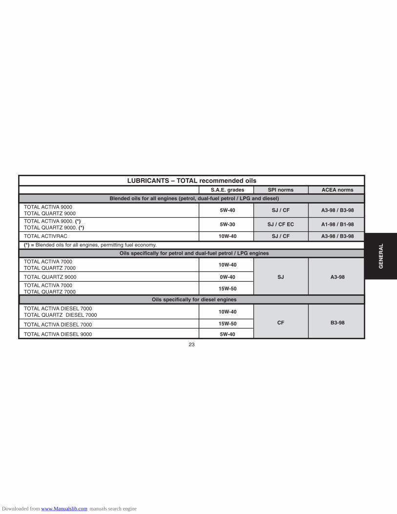
Blended oils for all engines (petrol, dual-fuel petrol / LPG and diesel)
TOTAL ACTIVA 9000TOTAL QUARTZ 9000
5W-40 SJ / CF A3-98 / B3-98
TOTAL ACTIVA 9000. (*)TOTAL QUARTZ 9000. (*)
5W-30 SJ / CF EC A1-98 / B1-98
TOTAL ACTIVRAC 10W-40 SJ / CF A3-98 / B3-98
(*) = Blended oils for all engines, permitting fuel economy.
Oils specifically for petrol and dual-fuel petrol / LPG engines
TOTAL ACTIVA 7000TOTAL QUARTZ 7000
10W-40
TOTAL QUARTZ 9000 0W-40 SJ A3-98
TOTAL ACTIVA 7000TOTAL QUARTZ 7000
15W-50
Oils specifically for diesel engines
TOTAL ACTIVA DIESEL 7000TOTAL QUARTZ DIESEL 7000
10W-40
TOTAL ACTIVA DIESEL 7000 15W-50 CF B3-98
TOTAL ACTIVA DIESEL 9000 5W-40
LUBRICANTS – TOTAL recommended oils
Downloaded from www.Manualslib.com manuals search engine

24
GE
NE
RA
L
FRANCE
Metropolitan FRANCE
Metropolitan FRANCE
New CaledoniaGuadeloupeSaint-MartinLa RéunionMartinique 9000 5W-40 7000 15W-50 7000 15W-50GuyanaTahitiMauritiusMayotte
LUBRICANTS – TOTAL RECOMMENDED OILS
Blended oils for all engines, supplied in bulk
TOTAL ACTIVRAC S.A.E : 10W-40 Norms
TOTAL ACTIVA
9000 5W-409000 5W-30 (*)
7000 10 W-40 7000 10W-409000 5W-40
TOTAL ACTIVA DIESEL
Blended oils for all engines Oils specifically for petrol anddual-fuel petrol / LPG engines
Oils specifically for dieselengines
(*) = Blended oils for all engines, permitting fuel economy.
Downloaded from www.Manualslib.com manuals search engine

25
GE
NE
RA
L
EUROPE
Germany
Austria
Belgium
Bulgaria
CyprusCroatia
Denmark
Spain
Estonia
Finland
Great Britain
LUBRICANTS – TOTAL RECOMMENDED OILS
TOTAL QUARTZ TOTAL QUARTZ DIESEL
Blended oils for all engines Oils specifically for petrol anddual-fuel petrol / LPG engines
Oils specifically for dieselengines
9000 5W-409000 5W-30 (*)
(*) = Blended oils for all engines,permitting fuel economy
7000 10W-409000 0W-40
7000 10W-40
7000 10W-409000 0W-40
7000 10W-407000 15W50
7000 10W-40
7000 10W-409000 0W-40
7000 10W-407000 15W-50
7000.10W-40
7000 10W-409000 0W-40
7000 10W-40
7000 10W-40
Downloaded from www.Manualslib.com manuals search engine

26
GE
NE
RA
L
Oils specifically for dieselengines
EUROPE (continued)
Greece
HollandHungaryItalyIrlandIcelandLatviaLithuaniaMacedonia
Malta
Moldova
Norway
PolandPortugalSlovak Republic
LUBRICANTS – TOTAL recommended oils
TOTAL QUARTZ TOTAL QUARTZ DIESEL
Blended oils for all enginesOils specifically for petrol anddual-fuel petrol / LPG engines
(*) = Blended oils for all engines,permitting fuel economy
9000 5W-40
9000 5W-30 (*)7000 10W-40
7000 10W-407000 15W-50
7000 10W-409000 0W-40
7000 10W-40
7000 10W-409000 0W-40
7000 10W-407000 10W-407000 15W-507000 10W-40
7000 10W-409000 0W-40
7000 10W-40
Downloaded from www.Manualslib.com manuals search engine

27
GE
NE
RA
L
EUROPE (continued)
Czech Republic 7000 10W-409000 0W-40
Roumania7000 10W-407000 15W-50
Russia7000 10W-409000 0W-40
Slovenia 7000 10W-40
Sweden7000 10W-409000 0W-40
Switzerland 7000 10W-40
7000 10W-40Turkey 7000 15W-50
9000 0W-40
Ukraine7000 10W-409000 0W-40
Yugoslavia 7000 10W-40
LUBRICANTS – TOTAL recommended oils
Oils specifically for dieselengines
TOTAL QUARTZ TOTAL QUARTZ DIESEL
Blended oils for all engines Oils specifically for petrol anddual-fuel petrol / LPG engines
(*) = Blended oils for all engines, per-mitting fuel economy
9000 5W-409000 5W-30 (*)
7000 10W-40
Downloaded from www.Manualslib.com manuals search engine
28
GE
NE
RA
L
Oils specifically for dieselengines
AustraliaNew-Zealand
Ivory CoastEgyptGabonMadagascarMoroccoSenegalTunisia
ArgentinaBrazil, ChileCubaMexicoParaguayUruguay
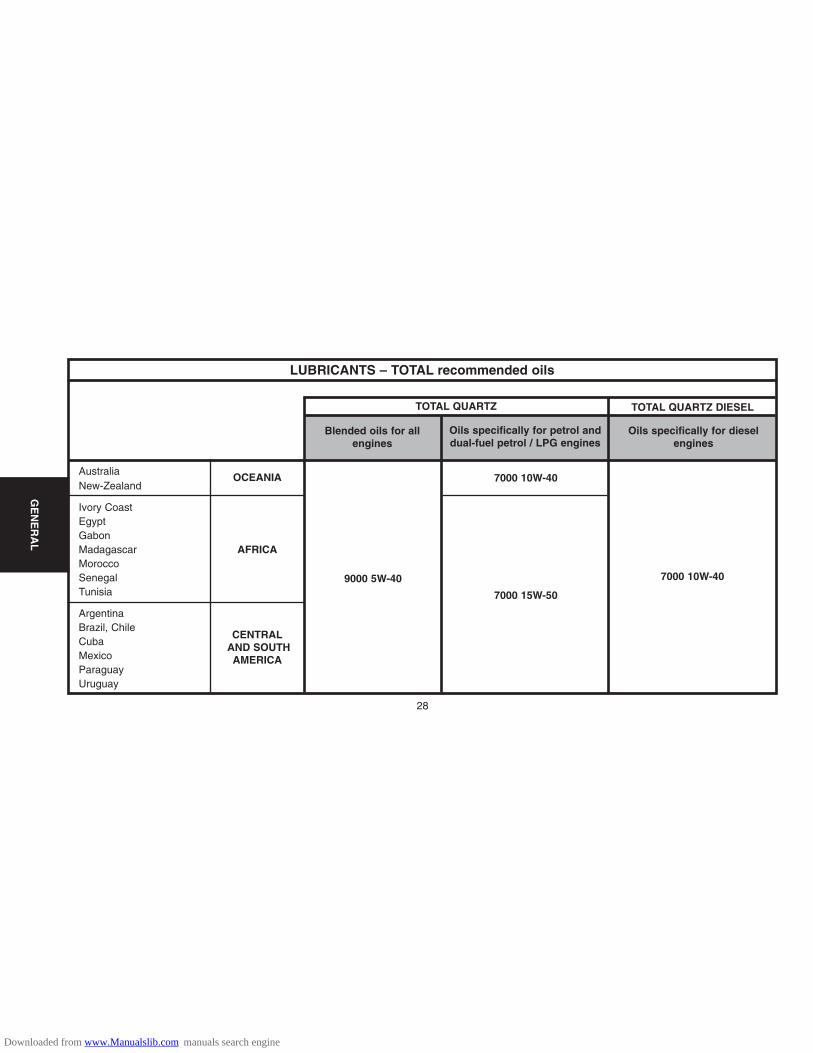
LUBRICANTS – TOTAL recommended oils
TOTAL QUARTZ TOTAL QUARTZ DIESEL
Blended oils for allengines
Oils specifically for petrol anddual-fuel petrol / LPG engines
OCEANIA
AFRICA
CENTRALAND SOUTHAMERICA
9000 5W-40
7000 10W-40
7000 15W-50
7000 10W-40
Downloaded from www.Manualslib.com manuals search engine
29
GE
NE
RA
L
Oils specifically for dieselengines
China
South Korea
Hong-KongIndiaIndonesia
Japan
MalaysiaPakistanPhilippinesSingapore
Taiwan
Thailand
Vietnam
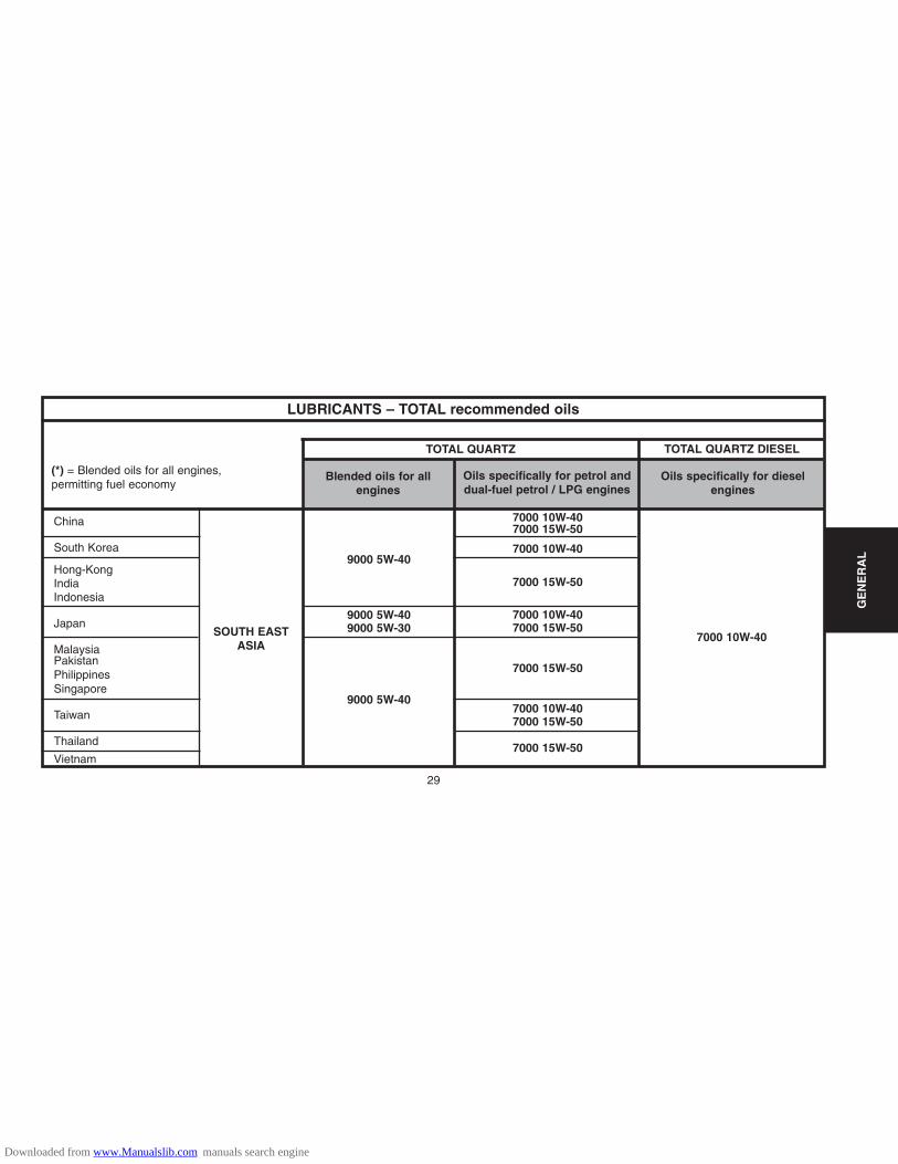
LUBRICANTS – TOTAL recommended oils
TOTAL QUARTZ TOTAL QUARTZ DIESEL
Blended oils for allengines
Oils specifically for petrol anddual-fuel petrol / LPG engines
SOUTH EASTASIA
9000 5W-40
9000 5W-409000 5W-30
9000 5W-40
7000 10W-407000 15W-50
7000 10W-40
7000 15W-50
7000 10W-407000 15W-50
7000 15W-50
7000 10W-407000 15W-50
7000 15W-50
7000 10W-40
(*) = Blended oils for all engines,permitting fuel economy
Downloaded from www.Manualslib.com manuals search engine

30
GE
NE
RA
L
Oils specifically for dieselengines
LUBRICANTS – TOTAL recommended oils
TOTAL QUARTZ TOTAL QUARTZ DIESEL
Blended oils for all enginesOils specifically for petrol anddual-fuel petrol / LPG engines
MIDDLEEAST 9000 5W-40 7000 15W-50 7000 10W-50
Saudi Arabia
Bahrain
Dubai
United Arab Emirates
Iran
Israel
Jordan
Kuwait
Lebanon
Oman
Qatar
Yemen
Downloaded from www.Manualslib.com manuals search engine

31
GE
NE
RA
L
Manual gearbox
TOTAL TRANSMISSION BVNorms S.A.E 75W-80
Special oil distributed by CITROËN(Part No. 9730 A2)
MB3 automatic gearbox All countries
TOTAL FLUIDE ATX ouTOTAL FLUIDE AT 42.
Special oils distributed by CITROËN(Part No. 9730 A3)
4 HP 20 and AL4 automatic gearboxesSpecial oil distributed by CITROËN
(Part No. 9736 22)
Transfer box and rear axle TOTAL TRANSMISSION X 4
All countries TOTAL FLUIDE ATX
Power- assisted steering TOTAL FLUIDE DAVery cold countries Special oil distributed by CITROËN
(Part No. 9730 A1)
LUBRICANTS – TOTAL recommended oilsGearbox oils
Power steering oils
Downloaded from www.Manualslib.com manuals search engine
32
GE
NE
RA
L
Engine coolant fluid
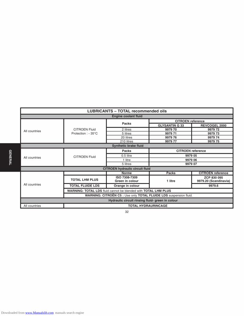
LUBRICANTS – TOTAL recommended oils
PacksCITROEN reference
GLYSANTIN G 33 REVCOGEL 2000CITROEN Fluid 2 litres 9979 70 9979 72All countries
Protection : - 35°C 5 litres 9979 71 9979 7320 litres 9979 76 9979 74
210 litres 9979 77 9979 75Synthetic brake fluid
Packs CITROEN reference
All countries CITROEN Fluid 0.5 litre 9979 051 litre 9979 065 litres 9979 07
CITROEN hydraulic circuit fluidNorme Packs CITROEN reference
TOTAL LHM PLUSISO 7308-7309 ZCP 830 095
Green in colour 1 litre 9979.20 (Scandinavia)All countries TOTAL FLUIDE LDS Orange in colour 9979.6
WARNING: TOTAL LDS fluid cannot be blended with TOTAL LHM PLUSWARNING: CITROËN C5 : Use only TOTAL FLUIDE LDS suspension fluid.
Hydraulic circuit rinsing fluid- green in colour
All countries TOTAL HYDRAURINCAGE
Downloaded from www.Manualslib.com manuals search engine

33
GE
NE
RA
L
Packs CITROEN reference
Concentrated : 250 ml 9980 33 ZC 9875 953 U 9980 56All countries
Liquid ready to use: 1 litre 9980 06 ZC 9875 784 U
Liquid ready to use: 5 litres 9980 05 ZC 9885 077 U ZC 9875 279 U
Grease
Norms NLGI (1)
TOTAL MULTIS EP2 2
All countries TOTAL MULTIS COMPLEX EP2 2
TOTAL MULTIS N4128 1
TOTAL PETITES MECANIQUES
(1) NLGI = National Lubricating Grease Institute.
Wash/wipe fluid
LUBRICANTS – TOTAL recommended oils
Downloaded from www.Manualslib.com manuals search engine
34
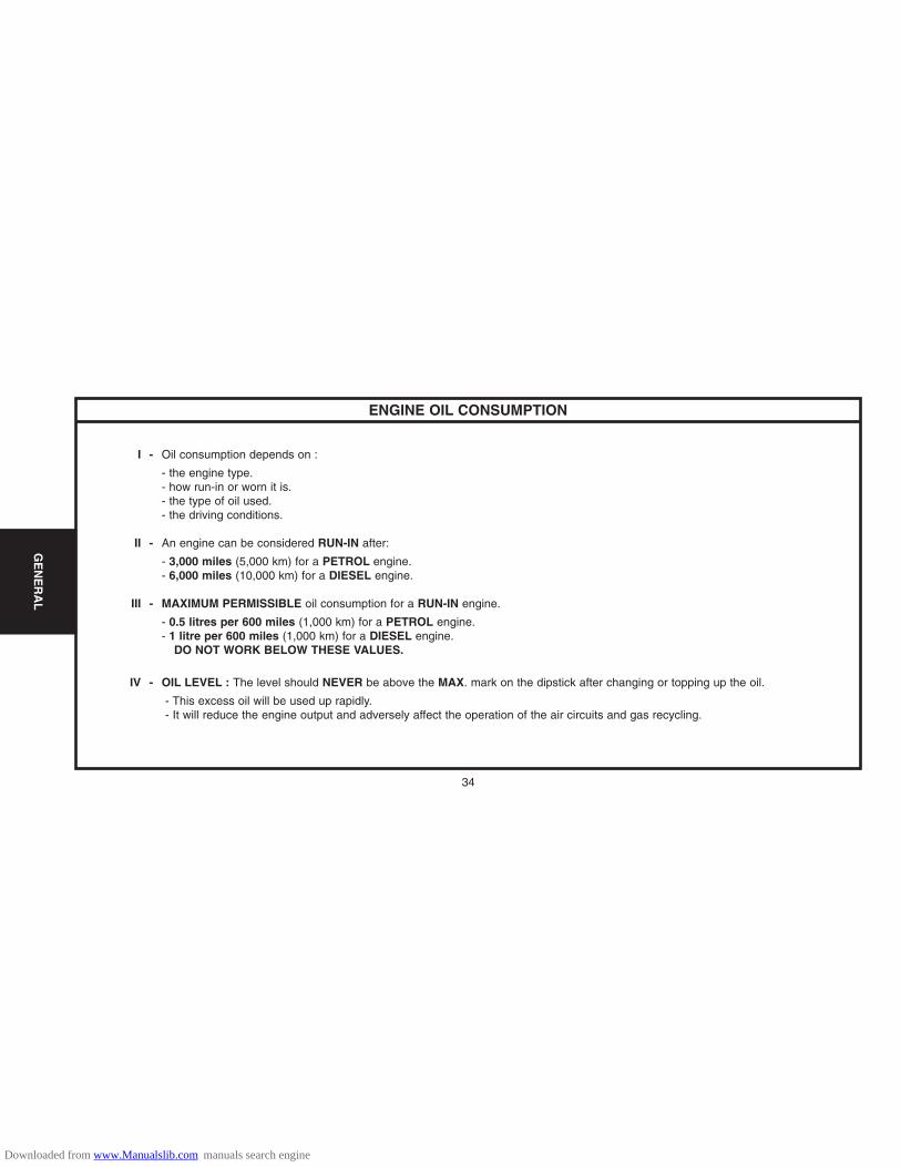
ENGINE OIL CONSUMPTION
I - Oil consumption depends on :
- the engine type.- how run-in or worn it is.- the type of oil used.- the driving conditions.
II - An engine can be considered RUN-IN after:
- 3,000 miles (5,000 km) for a PETROL engine.- 6,000 miles (10,000 km) for a DIESEL engine.
III - MAXIMUM PERMISSIBLE oil consumption for a RUN-IN engine.
- 0.5 litres per 600 miles (1,000 km) for a PETROL engine.- 1 litre per 600 miles (1,000 km) for a DIESEL engine.
DO NOT WORK BELOW THESE VALUES.
IV - OIL LEVEL : The level should NEVER be above the MAX. mark on the dipstick after changing or topping up the oil.
- This excess oil will be used up rapidly.- It will reduce the engine output and adversely affect the operation of the air circuits and gas recycling.
GE
NE
RA
L
Downloaded from www.Manualslib.com manuals search engine

35
ENGINE SPECIFICATIONS
DieselPetrol
1.1i 1.4i 1.6i 16V 1.4 HDi
Engine type
Cubic capacity (cc)
Bore / Stroke
Compression ratio
Power ISO or EEC KW - rpm
Power DIN (HP - rpm)
Torque ISO or EEC (m.daN - rpm)
Torque DIN (mkg-rpm)
HFX KFV NFU 8HX
1124 1360 1587 1398
72/69 75/77 78/82 73/82
10.5/1 11/1 17.9/1
44-5500 54-5400 80-5800 50-4000
61-5500 75-5400 110-5800 70-4000
9.4-3400 12-3400 14.7-4000 15-2000
9.8-3400 12.5-3400 15.3-4000 15.6-2000
EN
GIN
E
Downloaded from www.Manualslib.com manuals search engine

36
ENGINE SPECIFICATIONSEngines : HFX - KFV - NFU
Engine identification
B1BP10JC B1BP2GKC
A = Engines : HFX - KFV
B = Engine : NFU
Compulsory engine identification in zone « a »:
- Component reference.
- Engine legislation type.
- Factory serial no.
EN
GIN
E
Downloaded from www.Manualslib.com manuals search engine

37
CYLINDER HEADEngines : HFX - KFV - NFU
Identification of cylinder head gasket
Engine types
HFX
KFV
NFU
Thicknesses(Standard)
1.2 ± 0.1
0.66 ± 0.04
Thicknesses (repair)
1.4 ± 0.1
Thickness references
2
1
4
EN
GIN
E
References
1.2.3.4 = Type of engine.
A,B,D = Suppliers.
C = Gasket material.
R = Repair.
B1BP10KC
Downloaded from www.Manualslib.com manuals search engine

38
CYLINDER HEADEngines : HFX - KFV - NFU
Cylinder head tightening (m.daN) Cylinder head bolts
X = MAXIMUM reusable length
Tightening 2 ± 0.2
Angular tightening 240° ± 5°
(In the order 1 to 10)
Tightening 2 ± 0.2Angular tightening 260° ± 5°
(In the order 1 to 10)
NOTE : Oil the threads andunder the heads of the bolts.(Use engine oil or Molykote GRapid Plus).
B1BP1DVC
NFU
HFX - KFV
HFX - KFV
175.5 ± 0.5 122 ± 0.3
NFU
B1DP05BC
NOTE : Retightening of the cylinder headafter a completed repair is prohibited.
EN
GIN
E
Downloaded from www.Manualslib.com manuals search engine

39
SPECIAL FEATURES : TIGHTENING TORQUES (m.daN)Crankshaft
Accessories drive pulley 2.5 ± 0.2
Pinion fixing on crankshaft
- Tightening 4 ± 0.4
- Angular tightening 45° ± 4°
Cylinder block
Sump 0.8 ± 0.2Timing belt tensioner roller 2.1 ± 0.2Accessories belt tensioner roller 2.5 ± 0.2Accessories belt guide roller 2.5 ± 0.2Alternator support 2.5 ± 0.2
Alternator TU1JP-TU3JP
- Pre-tightening 1 ±- Tightening 3.7 ± 0.3Alternator TU5JP4
- Pre-tightening 1 ±- Tightening 4 ± .04
Aircon compressor support 2.2 ± 0.2Aircon compressor 2.3 ± 0.2
EN
GIN
E
Downloaded from www.Manualslib.com manuals search engine
40
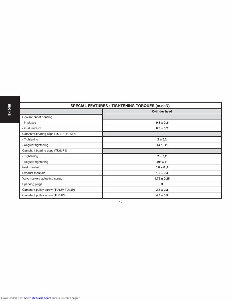
SPECIAL FEATURES : TIGHTENING TORQUES (m.daN)Cylinder head
Coolant outlet housing
- in plastic 0.8 ± 0.2
- in aluminium 0.8 ± 0.2
Camshaft bearing caps (TU1JP-TU3JP)
- Tightening 2 ± 0,2
- Angular tightening 44 °± 4°
Camshaft bearing caps (TU5JP4)
- Tightening 2 ± 0,2
- Angular tightening 50° ± 5°
Inlet manifold 0.8 ± 0.,2
Exhaust manifold 1.8 ± 0.4
Valve rockers adjusting screw 1.75 ± 0.25
Sparking plugs 3
Camshaft pulley screw (TU1JP-TU3JP) 3.7 ± 0.2
Camshaft pulley screw (TU5JP4) 4.5 ± 0.5
EN
GIN
E
Downloaded from www.Manualslib.com manuals search engine
41
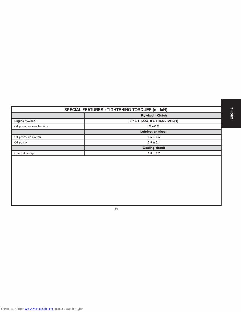
SPECIAL FEATURES : TIGHTENING TORQUES (m.daN)Flywheel - Clutch
Engine flywheel 6.7 ± 1 (LOCTITE FRENETANCH)
Oil pressure mechanism 2 ± 0.2
Lubrication circuit
Oil pressure switch 3.5 ± 0.5
Oil pump 0.9 ± 0.1
Cooling circuit
Coolant pump 1.6 ± 0.2
EN
GIN
E
Downloaded from www.Manualslib.com manuals search engine

42
TIGHTENING TORQUES : POWER UNIT SUSPENSION Engines : HFX - KFV - NFU
(1) : 6 ± 0.6
(2) : 6 ± 0.6
(3) : 4.5 ± 0.4
(4) : 6 ± 0.6
(5) : 6 ± 0.6
(6) : 8.5 ± 0.8
(7) : 6 ± 0.6
(8) : 3 ± 0.3
(9) : 6 ± 0.6
(10) : 5.5 ± 0.5
B1BP2Y3P
EN
GIN
E
Downloaded from www.Manualslib.com manuals search engine

43
EN
GIN
EENGINE SPECIFICATIONSEngine : 8HX
Engine identification
"a" Engine legislation type.
"b"Component reference.
"c" Factory serial no.
B1CP0BKD
Downloaded from www.Manualslib.com manuals search engine

44
EN
GIN
E
CYLINDER HEADEngine : 8HX
Cylinder head tightening (m.daN) Cylinder head bolts
X = MAXIMUM reusable length
Pre-tightening 2 ± 0.2 m.daN
Tightening 4 ± 0.4 m.daN
Angular tightening 230° ± 5°
(In the order 1 to 10)
NOTE :
- The bolts should have been tho-roughly cleaned and dried with adry metal brush.
- Oil the threads and under theheads of the bolts. (Use engineoil or Molykote G Rapid Plus).
- Pass a tap into the holes in thecylinder block.
8HX
8HX
X = 149 mm B1DP1CLC
B1DP1DBC
NOTE : Retightening of the cylinder headafter a completed repair is prohibited.
The cylinder head gasket is dry-fitted.
Downloaded from www.Manualslib.com manuals search engine
45
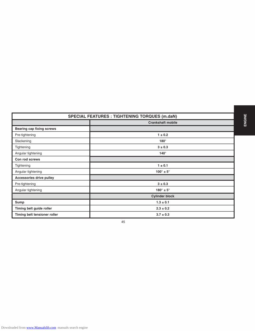
SPECIAL FEATURES : TIGHTENING TORQUES (m.daN)Crankshaft mobile
Bearing cap fixing screws
Pre-tightening 1 ± 0.2
Slackening 180°
Tightening 3 ± 0.3
Angular tightening 140°
Con rod screws
Tightening 1 ± 0.1
Angular tightening 100° ± 5°
Accessories drive pulley
Pre-tightening 3 ± 0.3
Angular tightening 180° ± 5°
Cylinder block
Sump 1.3 ± 0.1
Timing belt guide roller 2.3 ± 0.2
Timing belt tensioner roller 3.7 ± 0.3
EN
GIN
E
Downloaded from www.Manualslib.com manuals search engine

46
SPECIAL FEATURES : TIGHTENING TORQUES (m.daN)Cylinder head
Camshaft bearing covers
Pre-tightening 0.3 ± 0.1
Tightening 1 ± 0.1
Fixing of camshaft sub-assemblies on cylinder head
Pre-tightening 0.3 ± 0.1
Tightening 1 ± 0.1
Exhaust manifold 3 ± 0.3
Camshaft pulley
Pre-tightening 0.3 ± 0.1
Tightening 4.3 ± 0.4
Engine flywheel
Flywheel
Pre-tightening 1.7 ± 0.2
Tightening 70° ± 5°
Clutch mechanism 2 ± 0.2
EN
GIN
E
Downloaded from www.Manualslib.com manuals search engine
47
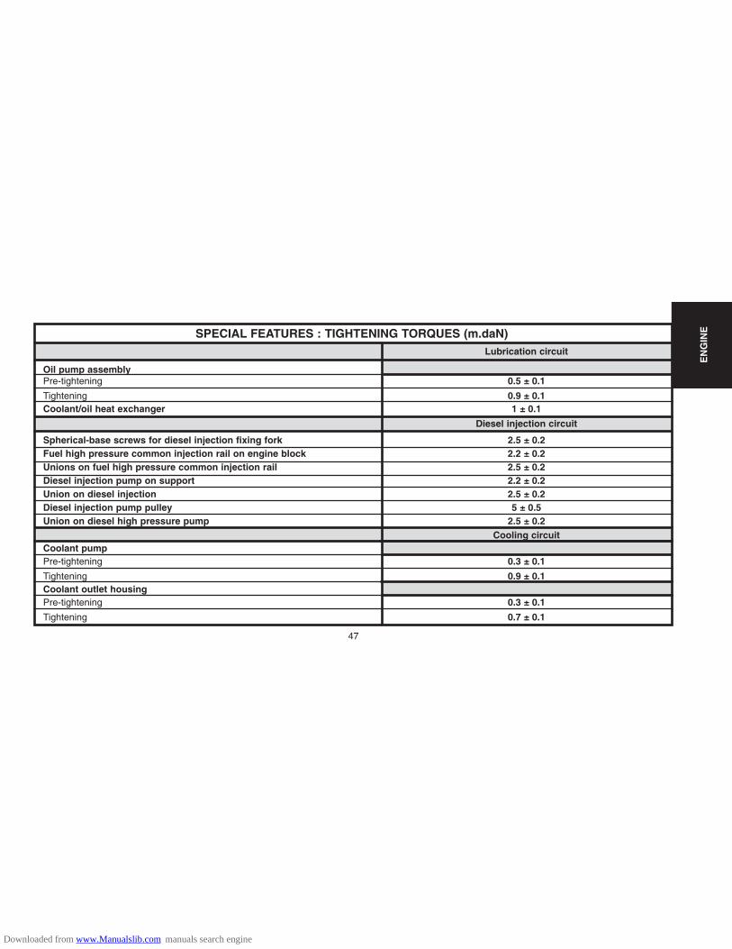
SPECIAL FEATURES : TIGHTENING TORQUES (m.daN)Lubrication circuit
Oil pump assemblyPre-tightening 0.5 ± 0.1
Tightening 0.9 ± 0.1Coolant/oil heat exchanger 1 ± 0.1
Diesel injection circuit
Spherical-base screws for diesel injection fixing fork 2.5 ± 0.2Fuel high pressure common injection rail on engine block 2.2 ± 0.2Unions on fuel high pressure common injection rail 2.5 ± 0.2Diesel injection pump on support 2.2 ± 0.2Union on diesel injection 2.5 ± 0.2Diesel injection pump pulley 5 ± 0.5Union on diesel high pressure pump 2.5 ± 0.2
Cooling circuitCoolant pumpPre-tightening 0.3 ± 0.1
Tightening 0.9 ± 0.1Coolant outlet housingPre-tightening 0.3 ± 0.1
Tightening 0.7 ± 0.1
EN
GIN
E
Downloaded from www.Manualslib.com manuals search engine

48
TIGHTENING TORQUES : POWER UNIT SUSPENSIONEngine : 8HX
(1) : 6 ± 0.6
(2) : 6 ± 0.6
(3) : 6 ± 0.6
(4) : 6 ± 0.6
(5) : 3 ± 0.3
(6) : 6 ± 0.6
(7) : 5.5± 0.5
(8) : 5.7 ± 0.9
B1BP2Y1P
EN
GIN
E
Downloaded from www.Manualslib.com manuals search engine

49
Tools
BELT TENSION/SEEM UNITS CORRESPONDENCE TABLE
! 4099-T (C.TRONIC.105) 4122-T (C.TRONIC.105.5) !
!!
B1EP135D
EN
GIN
E
Downloaded from www.Manualslib.com manuals search engine
50
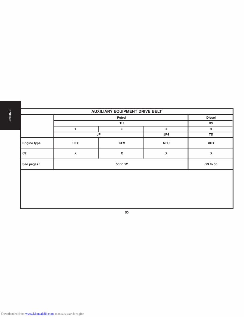
Engine type HFX KFV NFU 8HX
C2 X X X X
See pages : 50 to 52 53 to 55
AUXILIARY EQUIPMENT DRIVE BELTPetrol Diesel
TU DV
1 3 5 4
JP JP4 TD
EN
GIN
E
Downloaded from www.Manualslib.com manuals search engine

51
AUXILIARY EQUIPMENT DRIVE BELTEngines : HFX - KFV - NFU
B1BP2LSC B1BP2LTC
Tools.
[1] Pliers for removing plastic pegs : 7504-T.[2] Belt tension measuring instrument : 4122-T.
Vehicle without air conditioning.
Refit.Refit the belt.Respect the following sequence: - Crankshaft pinion.- Alternator pulley.Place tool [2] on the belt.Tighten screw (1) to achieve a tension of:
55 ± 3 unités SEEM.Tighten:- Screw (3).- Screw (2).Remove tool [2] and complete the refitting.
Remove.
Slacken:
- Screw (2).- Screw (3).- Tensioning screw (1).
Push the alternator back towards the engine.Remove the belt.
EN
GIN
E
Downloaded from www.Manualslib.com manuals search engine

52
AUXILIARY EQUIPMENT DRIVE BELTEngines : HFX - KFV - NFU
B1BP10XC
Vehicle with air conditioning.
RemoveSlacken:- Screws (6), (4) and (5).- Fully detension the belt by acting on the tensioner roller.- Remove the accessories drive belt.
Refit.Respect the following sequence: - Crankshaft pinion.- Aircon compressor pulley.- Guide roller.- Alternator pulley.- Tensioner roller.Place tool [2] on the belt.- Tighten screw (5) to achieve a belt tension of:
120 ± 3 SEEM units.- Tighten screws (4) and (6).- Remove tool [2].- Complete the refitting.
EN
GIN
E
B1BP10VC
Downloaded from www.Manualslib.com manuals search engine

53
AUXILIARY EQUIPMENT DRIVE BELTEngine : 8HXWith compressor and alternator
B1BP2MKCB1BP2MJD
Tools [1] Pliers for removing plastic pegs : 7504-T.[2] Tensioner roller compression lever : (-).0194.E.[3] Tensioner roller setting peg Ø4 mm : (-).0194.F.
Removing.Disconnect the battery negative cable.Raise and support the vehicle, wheels hanging.Remove the front RH wheel.Move aside the splash-shield, using tool [1].
IMPERATIVE : In the case of belt re-use, mark the direc-tion of rotation of the belt. If the index on the tensionerroller is outside the marks, change the auxiliary equip-ment drive belt.Remove :The alternator (1).The aircon compressor (2).Detension the auxiliary belt tensioner roller, using tool [2].Position the peg [3]. Remove the auxiliary drive belt.
EN
GIN
E
Downloaded from www.Manualslib.com manuals search engine

54
AUXILIARY EQUIPMENT DRIVE BELTEngine : 8HX
Markings on the dynamic tensioner roller.«a» Position of «maximum wear» of the auxiliary drive belt.«b» Normal position.
Refitting
NOTE : Check that the tensioner roller moves freely (no tight spot). If this is not thecase, replace the tensioner roller.
Respect the direction of fitting of the drive belt.
Complete the setting of the belt, of both sides, by means of the tensioner roller.Make sure that the drive belt is correctly positioned in the «V» grooves of thevarious pulleys.
Move the tool [2] on the tensioner roller to remove the peg [3].
EN
GIN
E
B1EP18UD
Downloaded from www.Manualslib.com manuals search engine

55
AUXILIARY EQUIPMENT DRIVE BELTEngine : 8HY
B1BP2MYD B1BP2MZC
Tools.
[1a] Dynamic tensioner roller lever : (-).0194-E1.[1b] Lever extension : (-).0194-E2.[2] Accessories belt roller locking peg Ø 4 mm : (-).0194-F
RemovingPivot the tensioner roller support (1) (clockwise), using tools [1a] and [1b] at «a».Remove the belt.Immobilise the support (1) of the tensioner roller, using tool [2].Remove the auxiliary drive belt (2).
IMPERATIVE : Ensure that the tensioner rollers turn freely (no play, no tight spot).
RefittingRefit the belt.Move the tool [1] on the tensioner roller to remove the peg [2].ESSENTIAL: Make sure that the belt is correctly positioned in the various pulleygrooves.
EN
GIN
E
Downloaded from www.Manualslib.com manuals search engine

56
EN
GIN
E
Engine type HFX KFV NFU 8HX
C2 X X X X
See pages : 57 to 66 67 to 83
CHECKING AND SETTING THE VALVE TIMINGPetrol Diesel
TU DV
1 3 5 4
JP JP4 TD
Downloaded from www.Manualslib.com manuals search engine

57
CHECKING AND SETTING THE VALVE TIMINGEngines : HFX - KFV - NFU
B1BP2M7C B1BP2M9CB1BP2M8C
Tools.[1] Engine flywheel peg : 4507-T.A[2] Camshaft pulley peg : 4507-T.B[3a] Camshaft peg : 4533-TA.C1[3b] Camshaft peg : 4533-TA.C2[4] Dynamic tensioner roller pin : 4200-T.H[5] Belt retaining pin : 4533-T.AD[6] Pliers for removing plastic pins : 7504-T.
Checking the valve timing.
Raise and support the front RH side of the vehicle.Disconnect the battery positive terminal.Engage 5th gear.Remove the oil filter (1).HFX - KFV engineRemove : The timing top casing (2).Turn the wheel to rotate the engine (normal direction of rotation).Peg the camshaft pulley, using tool [2].
EN
GIN
E
Downloaded from www.Manualslib.com manuals search engine

58
CHECKING AND SETTING THE VALVE TIMINGEngine : NFU
B1BP2MAC
Checking the timing (continued)
Engine: NFU
Place a jack under the engine, peg the engine.Remove:
- The engine support (4) complete.- The timing casing (3).- The sparking plugs (eases engine rotation).
Turn the wheel to rotate the engine (normal direction of rotation).Position the pegs [3a] and [3b].Peg the flywheel, using tool [1].If the setting is not correct, recommence the operation.Remove the tools [1], [2], [3a] and [3b].Complete the refitting.
B1BP2MBC
EN
GIN
E
B1EP18MC
Downloaded from www.Manualslib.com manuals search engine

59
CHECKING AND SETTING THE VALVE TIMINGEngines : HFX - KFV
B1BP2MBCB1BP2M9C B1BP2MDC
Setting the timingPreliminary operation.Lift and support the vehicle, wheels hanging.Disconnect the battery.Remove:- The front RH wheel.- The splash-shield, using tool [6]- The accessories belt (See corresponding operation).- The crankshaft pulley.- The oil filter.Place a jack under the engine, peg the engine.
Removing.HFX - KFV engineTurn the engine by means of screw (1). (normal direction of rotation).Remove the timing casings.Peg the camshaft pinion, using tool [2].Peg the flywheel, using tool [1].Remove:- The fixing screws (2).- The upper engine support (3).
EN
GIN
E
B1BP2MCC
Downloaded from www.Manualslib.com manuals search engine

60
CHECKING AND SETTING THE VALVE TIMINGEngines : HFX - KFV
B1BP2MEC B1EP18NC
Setting the timing (continued)
HFX - KFV engines
Slacken the screws (4) without removing them.
Remove the bottom engine support assembly (5), and the fixing screws (4).
Slacken the nut (6).
Completely detension the belt by acting on the tensioner roller (7).
Remove the timing belt.
IMPERATIVE : Check that the tensioner roller turns freely (no tight spot).
EN
GIN
E
Downloaded from www.Manualslib.com manuals search engine
61
CHECKING AND SETTING THE VALVE TIMINGEngine : NFU
B1BP2MBC
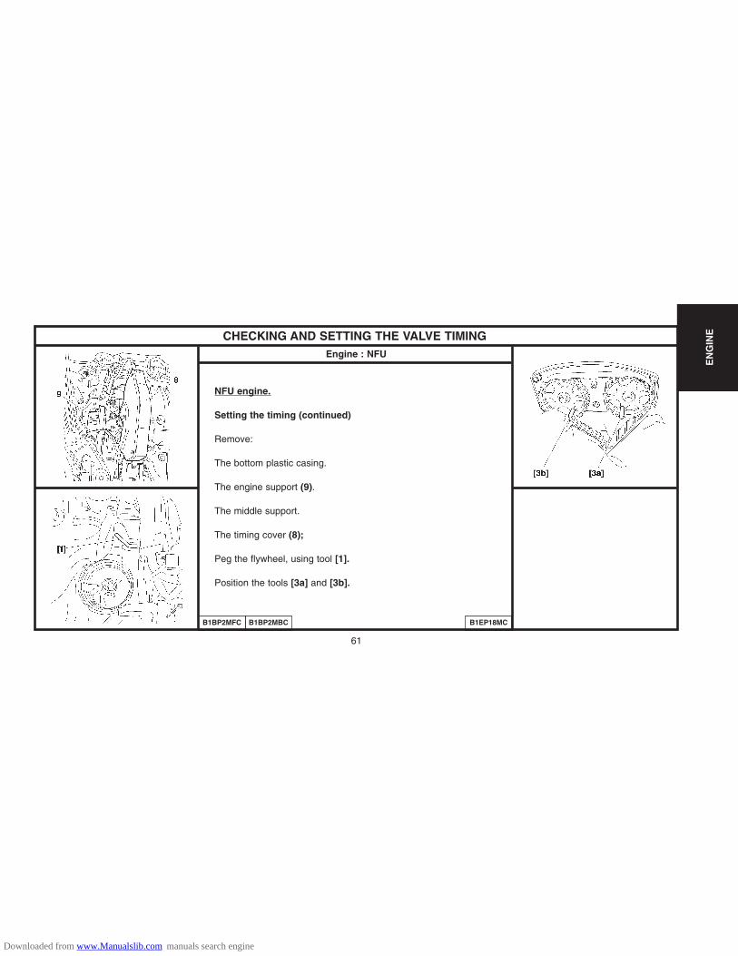
NFU engine.
Setting the timing (continued)
Remove:
The bottom plastic casing.
The engine support (9).
The middle support.
The timing cover (8);
Peg the flywheel, using tool [1].
Position the tools [3a] and [3b].
EN
GIN
E
B1BP2MFC B1EP18MC
Downloaded from www.Manualslib.com manuals search engine

62
CHECKING AND SETTING THE VALVE TIMINGEngine : NFU
B1EP18PC
Setting the timing (continued)
NFU engine.
Slacken the tensioer roller.
Turn the tensioner roller so as to be able to position the tool [4], with the aid of an Allen key placed at «a».
Turn the tensioner roller towards the right to bring it to the index «c» in position «b».
Peg the tensioner roller in this position in order to slacken the timing belt to the maximum.
IMPERATIVE : Never make the dynamic tensioner roller turn by a complete rotation.
Remove the timing belt (8).
Check that the rollers (9) and (10) turn freely (no tight spot).
EN
GIN
E
B1EP18QC
Downloaded from www.Manualslib.com manuals search engine

63
CHECKING AND SETTING THE VALVE TIMINGEngines : HFX - KFV
B1EP18QC
Setting the timing (continued)
HFX - KFV engines
Refit.
WARNING: Respect the direction of fitting of the belt: (the arrows «d» indicate the direction of rotation ofthe crankshaft).
Refit the timing belt.
Position the timing belt, belt «e» well tensioned, in the following order:Crankshaft pinion, hold the belt using tool [5].Camshaft pulley.Coolant pump pulley.Tensioner roller.Remove the pegs [1] and [2].
EN
GIN
E
Downloaded from www.Manualslib.com manuals search engine

64
CHECKING AND SETTING THE VALVE TIMINGEngines : KFX - KFV - NFU
Setting the timing (continued)HFX - KFV enginesRefitting.NOTE : Check that the pegs [1] and [2] are in place.WARNING: Respect the direction of fitting of the timing belt, the arrows «d» indicate the direction of rotationof the crankshaft.Refit the timing belt.Position the timing belt, belt «e» well tensioned, in the following order:Crankshaft pinion, hold the belt using tool [5].- Camshaft pulley.- Coolant pump pulley.- Tensioner roller.Remove the tools [1], [2].NFU engine.Fit the timing belt in position in the following order: - Inlet camshaft pulley.- Exhaust camshaft pulley.- Guide roller.- Crankshaft pulley.Position tool [5].- Coolant pump pulley.- Dynamic tensioner roller.Remove the tools [1], [3] and [5].
EN
GIN
E
B1EP18RC
Downloaded from www.Manualslib.com manuals search engine
65
CHECKING AND SETTING THE VALVE TIMINGEngines : KFX - KFV - NFU
B1EP18SD
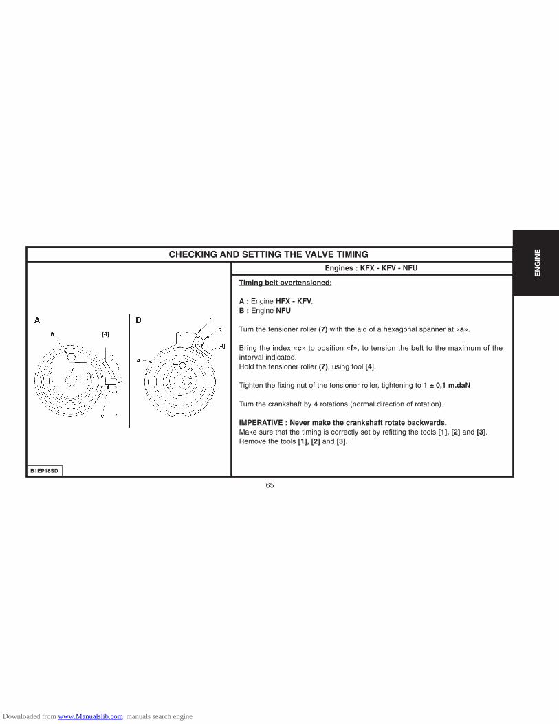
Timing belt overtensioned:
A : Engine HFX - KFV.B : Engine NFU
Turn the tensioner roller (7) with the aid of a hexagonal spanner at «a».
Bring the index «c» to position «f», to tension the belt to the maximum of theinterval indicated.Hold the tensioner roller (7), using tool [4].
Tighten the fixing nut of the tensioner roller, tightening to 1 ± 0,1 m.daN
Turn the crankshaft by 4 rotations (normal direction of rotation).
IMPERATIVE : Never make the crankshaft rotate backwards.Make sure that the timing is correctly set by refitting the tools [1], [2] and [3].Remove the tools [1], [2] and [3].
EN
GIN
E
Downloaded from www.Manualslib.com manuals search engine

66
CHECKING AND SETTING THE VALVE TIMINGEngines : HFX - KFV - NFU
B1EP18TD
Adjusting the fitting tension of the timing belt
A : Engine HFX - KFV.B : Engine NFU
Slacken the nut while maintaining the position of the tensioner roller, with the aid ofa hexagonal spanner at «a».Next bring the index «c» to its adjusting position «a».The index «c» should not go beyond the notch «g».
WARNING: The index «c» must not go beyond the notch «g». If it should do this,restart the timing belt tensioning operation.
Hold the tensioner roller (7) in this position, with the aid of a hexagonal spanner.Tighten the tensioner roller fixing nut to :
2 ± 0.2 m.daN. (HFX - KFV engines)2.2 ± 0.2 m.daN. (NFU engines)
IMPERATIVE : The tensioner roller must not rotate during the tightening of itsfixing. If it does, restart the timing belt tensioning operation.Complete the refitting.
EN
GIN
E
Downloaded from www.Manualslib.com manuals search engine

67
CHECKING AND SETTING THE VALVE TIMINGEngine : 8HX
B1BP2LXC
Tools.[1] Pliers for removing plastic pegs : 7504-T.[2] Lever for detensioning the dynamic tensioner roller : (-).0194.E[3] Engine flywheel setting peg : (-).0194.C[4] Camshaft setting peg : (-).0194.B.[5] Crankshaft and high pressure pump setting peg : (-).0194.A.Preliminary operations.Remove: - The front RH wheel.- The front RH splash-shield, using tool [1].- The clips of the electrical harness on the upper timing cover.- The accessories belt, using tool [2] (see corresponding operation).Check ing the setting.Disconnect the battery negative cable.Remove the upper timing cover (1).Rotate the engine using the screw (2) of the crankshaft pulley.
NOTE : The locking hole is located under the crankshaft bearing cap cover.Undo the screw (2).Detension the auxiliary drive belt dynamic tensioner roller, using tool [2].
EN
GIN
E
Downloaded from www.Manualslib.com manuals search engine
68
CHECKING AND SETTING THE VALVE TIMINGEngine : 8HX
B1EP18EC
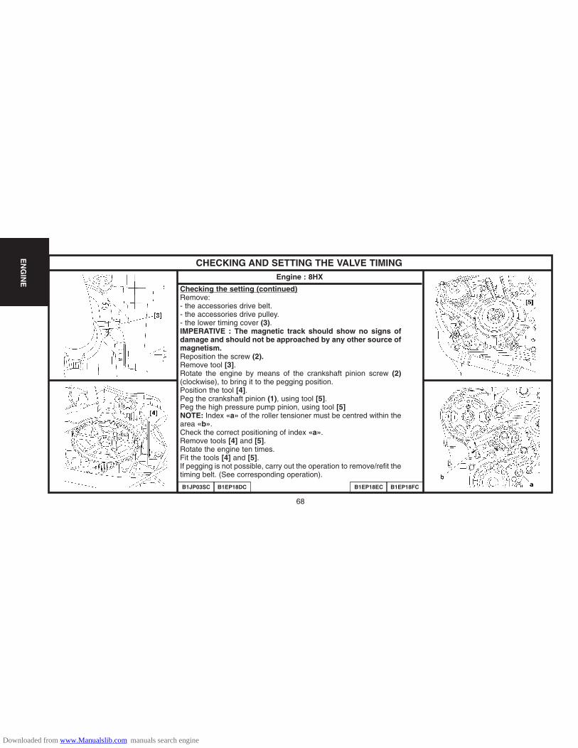
Checking the setting (continued)Remove: - the accessories drive belt.- the accessories drive pulley.- the lower timing cover (3).IMPERATIVE : The magnetic track should show no signs ofdamage and should not be approached by any other source ofmagnetism.Reposition the screw (2).Remove tool [3].Rotate the engine by means of the crankshaft pinion screw (2)(clockwise), to bring it to the pegging position.Position the tool [4].Peg the crankshaft pinion (1), using tool [5].Peg the high pressure pump pinion, using tool [5]NOTE: Index «a» of the roller tensioner must be centred within thearea «b».Check the correct positioning of index «a».Remove tools [4] and [5].Rotate the engine ten times.Fit the tools [4] and [5].If pegging is not possible, carry out the operation to remove/refit thetiming belt. (See corresponding operation).
B1JP03SC B1EP18DC B1EP18FC
EN
GIN
E
Downloaded from www.Manualslib.com manuals search engine

69
CHECKING AND SETTING THE VALVE TIMINGEngine : 8HX
B1EP18GC
Setting the timing.
Remove the upper timing cover (1).Rotate the engine by means of the crankshaft screw (2).NOTE : The pegging hole is located under the crankshaft bearing cap cover.Peg the engine flywheel, using tool [3].Remove the lower timing cover (3).Uncouple the exhaust line from the manifold.
IMPERATIVE : Uncouple the exhaust line in order to avoid damaging the front flexible pipe. Twisting,pulling and bending the front flexible pipe reduces its life.Remove: - The engine speed sensor (6).- The belt retaining stop (5).- The screw (2).- The crankshaft pinion (4) (with its magnetic track «a»).IMPERATIVE : The magnetic track should show no signs of damage and should not be approachedby any other source of magnetism. Should this not be adhered to, it is essential to replace thecrankshaft pinion.Refit the screw (2).
EN
GIN
E
B1BP2LXC
Downloaded from www.Manualslib.com manuals search engine

70
CHECKING AND SETTING THE VALVE TIMINGEngine : 8HX
Setting the timing (continued).
Remove the tool [3].
Rotate the engine by means of the crankshaft pinion screw (2)(clockwise), to bring it to the pegging position.
Peg the camshaft pulley, using tool [4].
Peg :- The crankshaft pinion (6), using tool [5].- The high pressure pump pinion, using tool [5].Support the engine with the aid of a roller jack equipped with achock.
Remove: - The RH engine support (7).- The intermediate engine support (right hand side) (8).
B1JP03SC B1EP18DC B1EP195C B1BP2LYC
EN
GIN
E
Downloaded from www.Manualslib.com manuals search engine
71
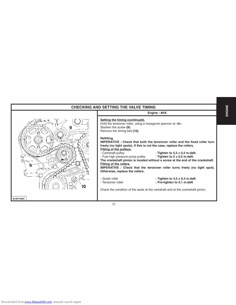
CHECKING AND SETTING THE VALVE TIMINGEngine : 8HX
B1EP18HC
Setting the timing (continued).Hold the tensioner roller, using a hexagonal spanner at «b».Slacken the screw (9).Remove the timing belt (10).
Refitting.IMPERATIVE : Check that both the tensioner roller and the fixed roller turnfreely (no tight spots). If this is not the case, replace the rollers.Fitting of the pulleys.- Camshaft pulley : Tighten to 4,3 ± 0,4 m.daN.- Fuel high pressure pump pulley : Tighten to 5 ± 0,5 m.daN.The crankshaft pinion is located without a screw at the end of the crankshaft. Fitting of the rollers.IMPERATIVE : Check that the tensioner roller turns freely (no tight spot).Otherwise, replace the rollers.
- Guide roller : Tighten to 4,5 ± 0,4 m.daN- Tensioner roller : Pre-tighten to 0,1 m.daN
Check the condition of the seals at the camshaft and at the crankshaft pinion.
EN
GIN
E
Downloaded from www.Manualslib.com manuals search engine

72
CHECKING AND SETTING THE VALVE TIMINGEngine : 8HX
B1EP18JD
Setting the timing (continued).
NOTE : Screw (9) slackened.
Position the timing belt (10) observing the following sequence:
Crankshaft pinion (4).
Guide roller (12).
Camshaft pulley (11), (check that the belt is held correctly against the roller).
Coolant pump pinion (13).
Fuel high pressure pump pulley (15).
Tensioner roller (14).
EN
GIN
E
Downloaded from www.Manualslib.com manuals search engine

73
EN
GIN
ECHECKING AND SETTING THE VALVE TIMINGEngine : 8HX
B1EP18KC
Setting the timing (continued).
Turn the tensioner roller to the right to bring the index «c» to position «d», using ahexagonal spanner.Tighten the screw (9) of the tensioner roller, tighten to 3 ± 0,3 m.daN.Remove the tools [4] and [5].
Rotate the engine ten times (check that the timing pinion is correctly up against thecrankshaft).
Check: The pegging of the camshaft.The crankshaft pinion.The fuel high pressure pump pinion (15).The correct positioning of the index of the dynamic tensioner.
If these are not correct, repeat the operation to position the timing belt.
Refit: The engine speed sensor (6).The belt retaining stop (5), tighten to 0,7 m.daN.
Downloaded from www.Manualslib.com manuals search engine

74
CHECKING AND SETTING THE VALVE TIMINGEngine : 8HX
B1EP18LC B1BP2LZC
Setting the timing (continued).
Refit:
The intermediate RH engine support, tighten the screws (16) to 5,5 ± 0,5 m.daN.The RH engine support, tighten the screws (17) to 4,5 ± 0,4 m.daN.The bottom timing cover (3).
Immobilise the engine flywheel, using tool [3].Remove the screw (2).Refit the accessories drive pulley and tighten to:
Pre-tighten to : 3 ± 0,3 m.daN.Angular tighten to : 180° ± 1,8°
Remove tool [3]Refit:The top cover (1).The accessories belt (see corresponding operation).The exhaust line (see corresponding operation).The front RH splash-shield.The front RH wheel.
EN
GIN
E
Downloaded from www.Manualslib.com manuals search engine
75
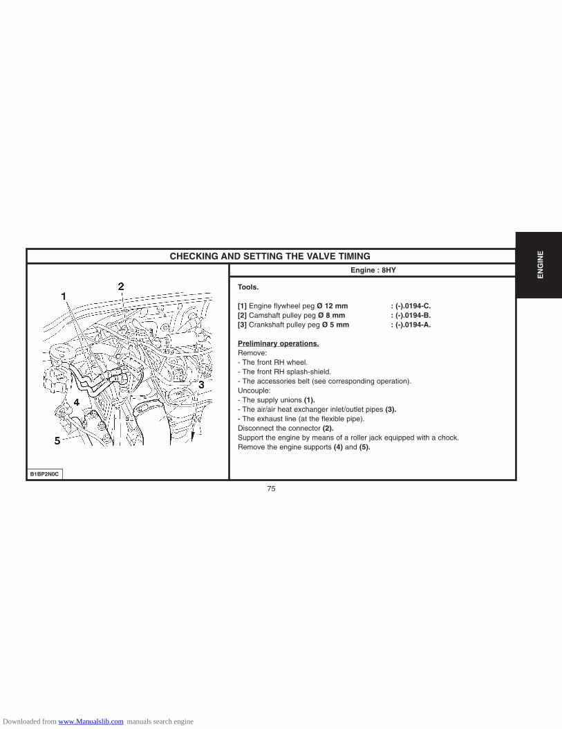
CHECKING AND SETTING THE VALVE TIMINGEngine : 8HY
B1BP2N0C
Tools.
[1] Engine flywheel peg Ø 12 mm : (-).0194-C.[2] Camshaft pulley peg Ø 8 mm : (-).0194-B.[3] Crankshaft pulley peg Ø 5 mm : (-).0194-A.
Preliminary operations.Remove: - The front RH wheel.- The front RH splash-shield.- The accessories belt (see corresponding operation). Uncouple: - The supply unions (1).- The air/air heat exchanger inlet/outlet pipes (3).- The exhaust line (at the flexible pipe).Disconnect the connector (2).Support the engine by means of a roller jack equipped with a chock.Remove the engine supports (4) and (5).
EN
GIN
E
Downloaded from www.Manualslib.com manuals search engine

76
CHECKING AND SETTING THE VALVE TIMINGEngine : 8HY
B1BP2N1C B1BP2N2C
Checks.
Rotate the engine to engage it (normal direction of rotation).Immobilise the engine flywheel at «a», using tool [1].Move aside the harness (6).
Remove:
- The engine support (7).
- The screw (8).
- The pulley (9).
- The lower timing cover (10).
- The upper timing cover (11).
- The tool [1].
EN
GIN
E
Downloaded from www.Manualslib.com manuals search engine
77
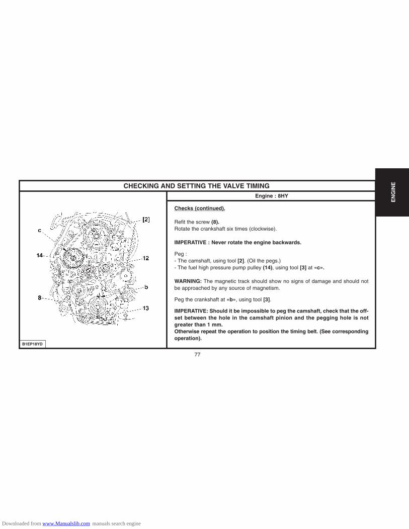
CHECKING AND SETTING THE VALVE TIMINGEngine : 8HY
B1EP18YD
Checks (continued).
Refit the screw (8).Rotate the crankshaft six times (clockwise).
IMPERATIVE : Never rotate the engine backwards.
Peg : - The camshaft, using tool [2]. (Oil the pegs.)- The fuel high pressure pump pulley (14), using tool [3] at «c».
WARNING: The magnetic track should show no signs of damage and should notbe approached by any source of magnetism.
Peg the crankshaft at «b», using tool [3].
IMPERATIVE: Should it be impossible to peg the camshaft, check that the off-set between the hole in the camshaft pinion and the pegging hole is notgreater than 1 mm.Otherwise repeat the operation to position the timing belt. (See correspondingoperation).
EN
GIN
E
Downloaded from www.Manualslib.com manuals search engine
78
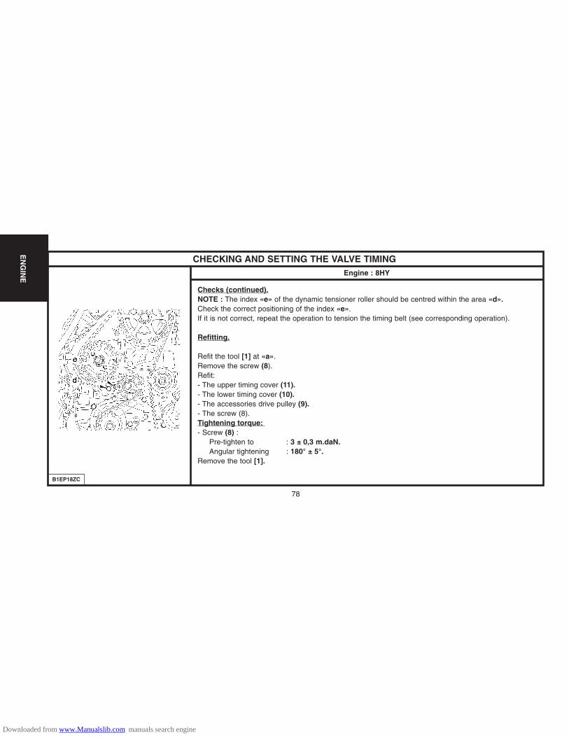
CHECKING AND SETTING THE VALVE TIMINGEngine : 8HY
B1EP18ZC
Checks (continued).NOTE : The index «e» of the dynamic tensioner roller should be centred within the area «d».Check the correct positioning of the index «e».If it is not correct, repeat the operation to tension the timing belt (see corresponding operation).
Refitting.
Refit the tool [1] at «a».Remove the screw (8).Refit: - The upper timing cover (11).- The lower timing cover (10).- The accessories drive pulley (9).- The screw (8).Tightening torque: - Screw (8) :
Pre-tighten to : 3 ± 0,3 m.daN.Angular tightening : 180° ± 5°.
Remove the tool [1].
EN
GIN
E
Downloaded from www.Manualslib.com manuals search engine

79
CHECKING AND SETTING THE VALVE TIMINGEngine : 8HY
B1BP2N0C
Checks (continued).
Refit : - The engine support (7), tighten to 1,5 ± 0,4 m.daN.- The engine support (4), tighten to 6,1 ± 0,6 m.daN.- The engine support (5), tighten to 6 ± 0,6 m.daN.- The electrical harness (6).
Couple: - The exhaust line, tighten the collar to : 2,5 ± 0,3 m daN- The fuel supply unions (1).- The air/air heat exchanger inlet/outlet pipes (3).Connect the connector (2).
Refit : - The accessories belt (see corresponding operation).- The front RH splash-shield (see corresponding operation).- The front RH road wheel, tighten to 9 ± 1 m.daN.Reconnect the battery.
EN
GIN
E
Downloaded from www.Manualslib.com manuals search engine

80
CHECKING AND SETTING THE VALVE TIMINGEngine : 8HY
B1EP18VD
Setting the timing.
Perform the preliminary operations for checking the timing up to removing tool [1] at «a» for immobiling theengine flywheel.Refit screw (8).Rotate the crankshaft to bring the camshaft towards its pegging point.Peg the camshaft, using tool [2]. (Oil the pegs).
WARNING: Do not press or damage the track which is the target for the engine speedsensor (14).
Peg the crankshaft at «b», using tool [3].Remove: - The timing protector (13).- The engine speed sensor (14).Slacken the screw (12) of the tensioner roller, keeping it slack with the aid of a hexagonal spanner at «c».Detension the belt by pivoting the tensioner roller (clockwise).Remove the timing belt, commencing with the coolant pump pinion.Peg the pulley (15), using a 5 mm diameter peg at «d».
EN
GIN
E
Downloaded from www.Manualslib.com manuals search engine
81
CHECKING AND SETTING THE VALVE TIMINGEngine : 8HY
B1EP18WD
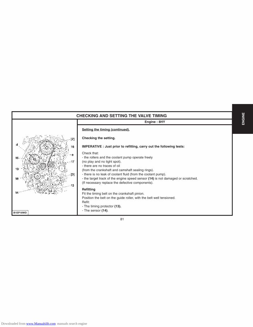
Setting the timing (continued).
Checking the setting.
IMPERATIVE : Just prior to refitting, carry out the following tests:
Check that:- the rollers and the coolant pump operate freely(no play and no tight spot).- there are no traces of oil (from the crankshaft and camshaft sealing rings).- there is no leak of coolant fluid (from the coolant pump).- the target track of the engine speed sensor (14) is not damaged or scratched.(If necessary replace the defective components).
RefittingFit the timing belt on the crankshaft pinion.Position the belt on the guide roller, with the belt well tensioned.Refit: - The timing protector (13).- The sensor (14).
EN
GIN
E
Downloaded from www.Manualslib.com manuals search engine

82
CHECKING AND SETTING THE VALVE TIMINGEngine : 8HY
B1EP18XC
Setting the timing (continued).
Checks (continued).
Reposition the timing belt, belt at «e» well tensioned, in the following order: - Guide roller (17).- Camshaft pulley (16).- Fuel high pressure pump pulley (15).- Coolant pump pinion (18).- Tensioner roller (19).Remove the 5 mm diameter peg at «d».Adjusting the fitting tension of the belt.Action the tensioner roller (19) to align the marks «f» and «g» , avoiding detensioning the timing belt,with the aid of a male hexagonal spanner, at «c».If this is not successful, repeat the operation to tension the belt.Hold the tensioner roller in position (19).Tighten the tensioner roller, tightening to 3,7 ± 0,3 m.daN.Check the position of the tensioner roller (the alignment of the marks «f» and «g» should be correct).Remove tools [2] and [3].Turn the crankshaft six rotations (clockwise).
EN
GIN
E
Downloaded from www.Manualslib.com manuals search engine
83
CHECKING AND SETTING THE VALVE TIMINGEngine : 8HY
B1EP18XC
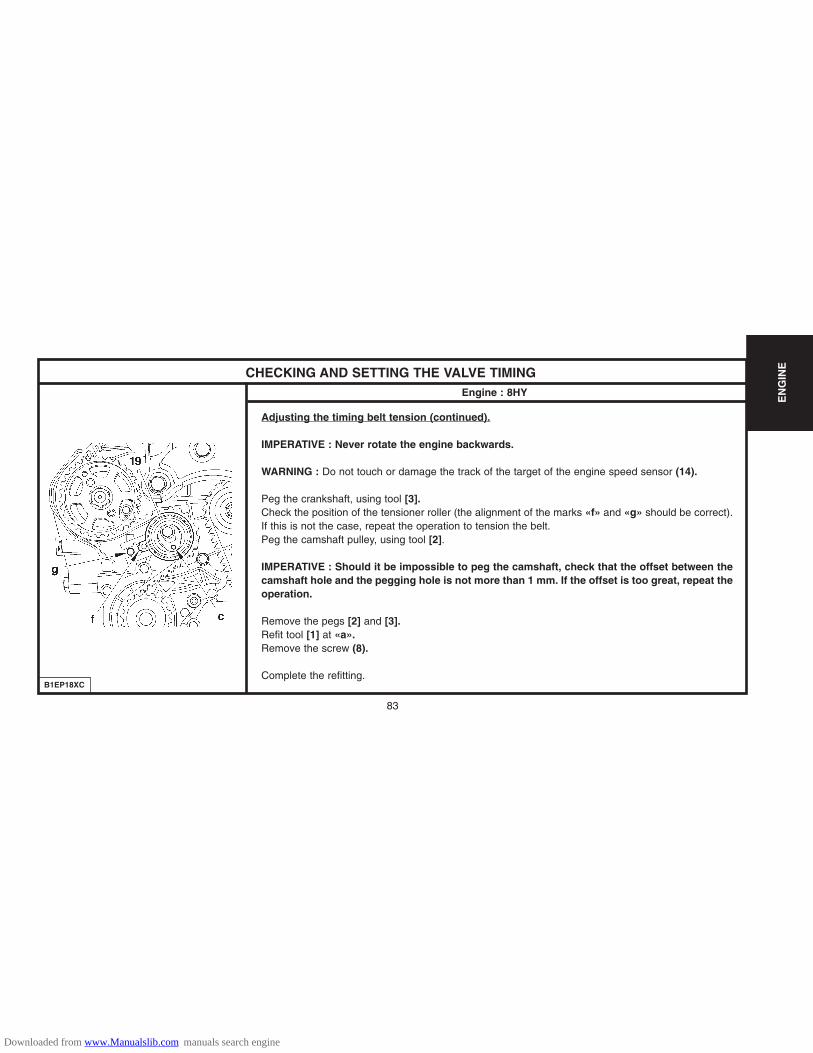
Adjusting the timing belt tension (continued).
IMPERATIVE : Never rotate the engine backwards.
WARNING : Do not touch or damage the track of the target of the engine speed sensor (14).
Peg the crankshaft, using tool [3].Check the position of the tensioner roller (the alignment of the marks «f» and «g» should be correct).If this is not the case, repeat the operation to tension the belt.Peg the camshaft pulley, using tool [2].
IMPERATIVE : Should it be impossible to peg the camshaft, check that the offset between thecamshaft hole and the pegging hole is not more than 1 mm. If the offset is too great, repeat theoperation.
Remove the pegs [2] and [3].Refit tool [1] at «a».Remove the screw (8).
Complete the refitting.
EN
GIN
E
Downloaded from www.Manualslib.com manuals search engine

84
EXHAUST SPECIFICATIONSEngines: HFX - KFV (Depollution L4)
B1JP03TD
EN
GIN
E
«a» Cutting zone
Downloaded from www.Manualslib.com manuals search engine

85
EXHAUST SPECIFICATIONSEngines: HFX - KFV (Depollution IFL5)
B1JP04RD
«a» Cutting zone
EN
GIN
E
Downloaded from www.Manualslib.com manuals search engine

86
EXHAUST SPECIFICATIONS
Engine: NFU (Depollution IFL5)
B1JP04TD
«a» Cutting zone
EN
GIN
E
Downloaded from www.Manualslib.com manuals search engine

87
EXHAUST SPECIFICATIONSEngine: HFX (Depollution L4 and IFL5)
(1) (2) (3) (4) (5) (6)
(1) (2) (3) (4) (5) (6)
(1) (2) (3) (4) (5)
Engine typeUpstream
oxygen sensor
Tightening (m.daN) Tightening (m.daN)
4.7 ± 0.5 TR PSA K179
TR PSA K208
TR PSA K181
4.7 ± 0.5
4.7 ± 0.5
4.7 ± 0.5
PSA 4173
PSA 4174
PSA 4176
PSA 4175
PSA 4175
PSA 96 362 494 80
PSA 96 362 494 80
0.8 ± 0.2
0.8 ± 0.2
HFX
KFV
NFU
Engine: KFV (Depollution L4 and IFL5)
Catalyticconverter
Downstreamoxygen sensor
Front silencer Rear silencer Air to exhaust injection valve
Upstreamoxygen sensor
Catalyticconverter
Downstreamoxygen sensor
Front silencer Rear silencer Air to exhaust injection valveEngine type
Tightening (m.daN) Tightening (m.daN)
4.7 ± 0.5
Engine : NFU (Depollution IFL5)
Engine type
EN
GIN
E
Tightening (m.daN)
Tightening (m.daN)
Upstreamoxygen sensor
Catalytic converterDownstream oxygen
sensorFront silencer Rear silencer
Tightening (m.daN) Tightening (m.daN)
4.7 ± 0.5
Downloaded from www.Manualslib.com manuals search engine

88
EXHAUST SPECIFICATIONSEngine : 8HX
EN
GIN
E
«a» Flexible pipe
«b» Cutting zone (marked by burrs)
«c» Silencer fixing strap
B1JP03PD
Downloaded from www.Manualslib.com manuals search engine

89
EXHAUST SPECIFICATIONS
Engine : 8HX
8HX
TR PSA K278
Tightening (m.daN) 2.5 ± 0.3 Tightening (m.daN) 2.5 ± 0.3 Tightening (m.daN) 2.5 ± 0.3
Engine types Catalytic converter
(1)
Strap
(2)
Intermediate pipe
(3)
Rear silencer
(4)
PSA 4177
EN
GIN
E
Downloaded from www.Manualslib.com manuals search engine

90
HFX KFV NFU 8HX
7 litres 5.7 Litres
16 dm3
1.4 bar 1.4 bar
89°C Start of opening 101°C Opening complete 83° C
100W (without aircon) 300W (with aircon) 1 x 300 W
97° C
115°C
118°C
105°C 6 minutes
COOLING SYSTEM SPECIFICATIONSEngines : HFX - KFV - NFU - 8HX
Engine type
Capacity
Radiator surface
Pressurisation
Opening of thermostatic regulator
Cooling fan
1st speed
2nd speed
Aircon cut-off
Warning
Post-cooling
1.4i. 1.6i 16V 1.4 HDi1.1i
Temperature sensor : Tighten to 1,7 ± 0,4 m.daN.
EN
GIN
E
Downloaded from www.Manualslib.com manuals search engine
91
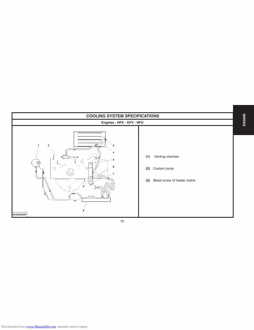
COOLING SYSTEM SPECIFICATIONS
Engines : HFX - KFV - NFU
(1) Venting chamber
(2) Coolant pump
(3) Bleed screw of heater matrix
B1GP0AXP
EN
GIN
E
Downloaded from www.Manualslib.com manuals search engine

92
EN
GIN
E
COOLING SYSTEM SPECIFICATIONS
Engine : 8HX
(1) Bleed screw (with or without aircon)
B1GP09MP
Downloaded from www.Manualslib.com manuals search engine

93
Petrol
Diesel
OIL FILTERS
TU
1
JP
1.1i
HFX KFV NFU
XFILTRAUTO X X
1.4i 1.6i 16V
3 5
JP4
DV
TD
1.4 HDi
8HX
XMALHEX
4
EN
GIN
E
Downloaded from www.Manualslib.com manuals search engine
94
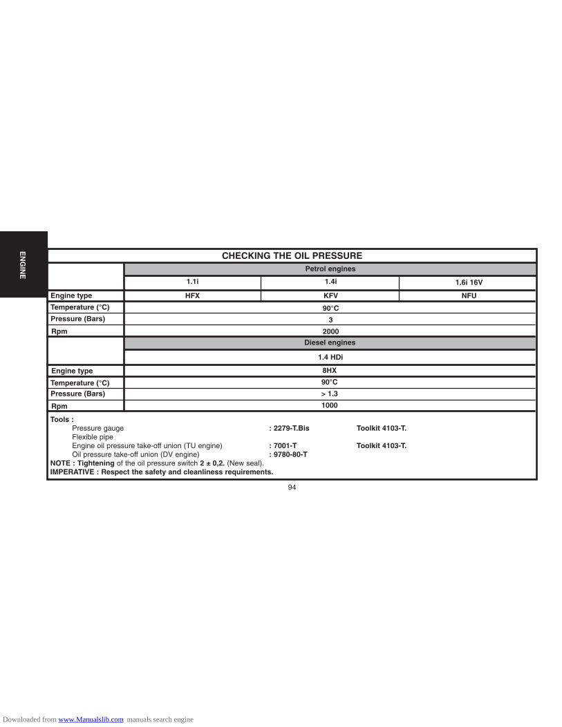
CHECKING THE OIL PRESSURE
Engine type
Temperature (°C)
Pressure (Bars)
Rpm
Engine type
Diesel engines
1.1i
HFX KFV NFU
90°C
3
2000
1.4i 1.6i 16V
1.4 HDi
8HX
90°C
> 1.3
1000
Petrol engines
Temperature (°C)Pressure (Bars)
Rpm
Tools :Pressure gauge : 2279-T.Bis Toolkit 4103-T.Flexible pipeEngine oil pressure take-off union (TU engine) : 7001-T Toolkit 4103-T.Oil pressure take-off union (DV engine) : 9780-80-T
NOTE : Tightening of the oil pressure switch 2 ± 0,2. (New seal).IMPERATIVE : Respect the safety and cleanliness requirements.
EN
GIN
E
Downloaded from www.Manualslib.com manuals search engine

95
VALVE CLEARANCES
The valve clearances should be checked with the engine cold.
� Inlet
HFX - KFV
NFU
8HX
0.20 mm ± 0.05
Exhaust
0.40 mm ± 0.05
1 mm ± 0.05
Hydraulic adjustment
1 mm ± 0.05
Rocking Adjust
1 � 1
3 � 3
4 � 4
2 � 2
4 � 4
2 � 2
1 � 1
3 � 3
Inlet
�
Admission
RockingValves
fullyopen
Adjust
1
3
4
2
3 � 4
4 � 2
2 � 1
1 � 3
Fully open (Exhaust)
POSSIBLE METHODSOn engines: 4 cylinders in line (1-3-4-2 )
Engines without hydraulicadjustment : the clearance (J)should be checked oppositethe cam.
B1DP13QC
EN
GIN
E
Downloaded from www.Manualslib.com manuals search engine

96
FILLING AND BLEEDING THE COOLING CIRCUIT
HFX-KFV-NFU
8HX
Tools[1] Filling cylinder : 4520-T[2] Adaptor for filling cylinder : 4222-T.[3] Pliers for removing-refitting elastic clips : 9029-T
Draining.
Perform the operation with the engine cold.Remove the air filter housing.Open the expansion chamber cap.Uncouple bottom hose (1), using tool [3] and bottom hose (2) of the radiator.
Open : The bleed screw on the coolant outlet housing.The bleed screw on the heater matrix.The cylinder block drain plug.
Allow the coolant to flow out.Before any refilling, rinse the cooling circuit with clean water.Couple the bottom hose (1) and (2).
B1BP2LUC B1GP0AQD
EN
GIN
E
Downloaded from www.Manualslib.com manuals search engine

97
EN
GIN
EFILLING AND BLEEDING THE COOLING CIRCUIT
Filling and bleeding.
Fit the filling cylinder [1], with the adaptor [2] on the filling aperture.Slowly fill the circuit with the coolant fluid.Reclose the bleed screws when the liquid starts to flow out continuously without air bubbles.
NOTE : The filling cylinder [1] should be filled to the «1 Litre» mark to purge the heater matrix correctly.
Refit the air filter housing.Start the engine.Maintain an engine speed of 1500 to 2000 rpm, until the end of the second cooling cycle.(Starting and stopping of the cooling fan).Keep the filling cylinder full to the «1 Litre» mark.Stop the engine after the second cooling cycle.Remove the filling cylinder [1] with the adaptor [2].Refit the expansion chamber cap.
B1GP09KC
Downloaded from www.Manualslib.com manuals search engine

IDLING - DEPOLLUTION
Vehicles Engine typeEmissionstandard
L4 MAGNETTI MARELLI 48P
SAGEM S2000
BOSCHM 7.4.4.
850 < 0.5 > 9
HFX
KFW
NFU
1.1 i
1.4 i
1.6 i 16V
IF/L5
L4
IF/L5
L4
Make - Injection type
% Content
CO CO2
Idling speed (± 50 rpm)
Manualgearbox
Auto. gearbox: Ngear engaged
C2
98
INJE
CT
ION
Downloaded from www.Manualslib.com manuals search engine

99
INJE
CT
ION
Emission standard
Engine type
Make Injection type
PETROL INJECTION
Air temperature sensorresistive value (ohms)
C2
M. MARELLI 48P2 SAGEM S2000 BOSCH M.7.4.4.
Fuel pressure (bars)
Overspeed cut-off (rpm)
Injector resistive value (ohms)
Engine coolant temperaturesensor resistive value (ohms)
Idling actuator or steppermotor resistive value (ohms)
HFX KFW NFU
L4 / IFL5 L4 L4
1.1i 1.4i 1.6i 16 V
3.5
5500 5800
14.5
Stepper motor : 53
3 800 at 10°C 2500 at 20° C 800 at 50°C 230 at 90° C
3 800 at 10°C 2500 at 20° C 800 at 50°C 230 at 90° C
Downloaded from www.Manualslib.com manuals search engine

100
INJE
CT
ION
STANDARD
Utility vehicles : All Types
Private vehicles : > 2 litres • new models • existing models
01/10/88 �01/10/89 �
� 10/89
en cours
� Utility vehicle limits = private vehicle limitsincreased by 25 %
� For private vehicles andutility vehicles in major export
Brussels directive 88/76 « Luxembourg Accords » � Replaced by 89/458 + 91/441
EMISSION STANDARDS
PSA
A/S RPEngines ApplicableVehicles
ECE R 15.04
ECE R 15.05 W vp 15.05 Petrol
E.E.C.
APPLICATIONS
NOTES CHARACTERISTICS
PetrolDiesel
K K’
15.0415.04
With oxygen sensor,without catalytic converter
Downloaded from www.Manualslib.com manuals search engine

STANDARD
NORMES DE DEPOLLUTION
PSA
A/S RPEngines ApplicableVehicles
US 83
US 87
US 93 Y2
Z
Y
US 83
US 87
US 93PetrolDiesel
PetrolDiesel
Diesel
E.E.C.
APPLICATIONS
NOTES CHARACTERISTICS
INJE
CT
ION
101
Current � Adoption of U.S. standard With oxygen sensor andcatalytic converter forpetrol vehicles
With catalytic converterand EGR
� Adoption of U.S. standard
� Adoption of U.S. standard
Current
Current
Private vehicles : • certain non-EECEuropean countries • certain Export countries
Private vehicles : • certain non-EECEuropean countries • certain Export countries
Private vehicles : • certain Export countries
Downloaded from www.Manualslib.com manuals search engine

INJE
CT
ION
102
STANDARD
NORMES DE DEPOLLUTION
PSA
A/S RPEngines ApplicableVehicles
US 84 LDT
US 87 LDT
US 90 LDT
X3
X1
X2
US 84
US 87
US 90PetrolDiesel
PetrolDiesel
PetrolDiesel
E.E.C.
APPLICATIONS
NOTES CHARACTERISTICS
Current � Adoption of the U.S.standard for light utilityvehicles
� Adoption of the U.S.standard for light utilityvehicles
� Adoption of the U.S.standard for light utilityvehicles
Current
Current
Utility vehicles : • certain non-EECEuropean countries • certain Export countries
Utility vehicles : • certain non-EECEuropean countries • certain Export countries
Private vehicles : • certain non-EECEuropean countries • certain Export countries
Downloaded from www.Manualslib.com manuals search engine

STANDARD
NORMES DE DEPOLLUTION
PSA
A/S RPEngines ApplicableVehicles
EURO 2
(EURO96)
EURO 2
(EURO96)
E.E.C.
APPLICATIONS
NOTES CHARACTERISTICS
INJE
CT
ION
103
L3CEE95
PetrolDiesel
Private vehicles : < 6 seats and < 2.5 tonnes • new models • existing models
Utility vehicles : < 3.5 tonnes Class 1 : • new models • existing models Class 2/3 : • new models • existing models
W3CEE95
Petrol Diesel Gas
01/97 �10/97 �
01/98 �10/98 �
01/96 �01/97 �
With oxygen sensor andreinforced catalyticconverter for petrolvehicles. With catalytic converterand EGR for dieselvehicles
With oxygen sensor andreinforced catalyticconverter for petrolvehicles. With catalytic converterand EGR for dieselvehicles.
Brussels Directive 96/69
� 3 classes depending onvehicle weight :
Class 1 < 1250 kg
Class 2 : 1250/1700 kg
Class 3 : 1700 kg
Brussels Directive 94/12
� EURO 93 standard madestricter
Downloaded from www.Manualslib.com manuals search engine

INJE
CT
ION
104
STANDARD
Utility vehicles : < 3.5 tonnes
Class 1 :
• new models
• existing models
Class 2/3 :
• new models
• existing models
Private vehicles : All Types
• new models • existing models
NORMES DE DEPOLLUTION
PSA
A/S RPEngines ApplicableVehicles
EURO 3
(EURO2000)
W3
EURO 4 IF / L5
E.E.C.
APPLICATIONS
NOTES CHARACTERISTICS
Petrol Diesel Gas
Petrol
With 2 oxygen sensorsand catalytic converter forpetrol vehicles. With catalytic converterand EGR for dieselvehicles.
With EOBD on-boarddiagnosis.
With 2 oxygen sensorsand catalytic converter forpetrol vehicles.
With EOBD on-boarddiagnosis.
Brussels Directive 98/69 � EURO 2 standard (L3)made stricter� Fiscal incentives� 3 classes depending onvehicle weight : Class 1 < 1305 kg Class 2 : 1305/1760 kg Class 3 : 1760 kg
Brussels Directive 99/102
� EURO 3 standard (L4)made stricter� Fiscal incentives
� 01/2000
� 01/2001
� 01/2001
� 01/2002
� 01/2005
� 01/2006
Downloaded from www.Manualslib.com manuals search engine

105
INJE
CT
ION
STANDARD
Private vehicles : All Types
• new models • existing models
NORMES DE DEPOLLUTION
PSA
A/S RPEngines ApplicableVehicles
EURO 4
EURO 4
E.E.C.
APPLICATIONS
NOTES CHARACTERISTICS
IF / L5
IF / L5
Petrol DieselGas
PetrolGas
Brussels Directive: 2001/1� EURO 3 standard (L4) madestricter� Fiscal incentives
Brussels Directives: 99/102 and2001/1 (Gas)� EURO 3 standard (L4) madestricter� Fiscal incentives� 3 classes depending onvehicle weight : Class 1 < 1305 kg Class 2 : 1305/1760 kg Class 3 : 1760 kg
With 2 oxygen sensors
and catalytic converter for
petrol vehicles.
With EOBD on-board
diagnosis.
With 2 oxygen sensors
and catalytic converter for
petrol vehicles.
With EOBD on-board
diagnosis.
� 01/2005� 01/2006
� 01/2005� 01/2006
� 01/2006� 01/2007
Utility vehicles : < 3.5 tonnes
Class 1 : • new models • existing models Class 2/3 : • new models • existing models
Downloaded from www.Manualslib.com manuals search engine

106
INJE
CT
ION
PROHIBITED OPERATIONS: SIEMENS HDI DIRECT INJECTION SYSTEM
Engine : 8HX
Cleaning.- The use of high pressure cleaners is prohibited.- Do not use compressed air.
Fuel supply circuit.- Required fuel : diesel.
Electric circuit.- Swapping injection ECUs between two vehicles will render it impossible to start either vehicle.- It is forbidden to supply a diesel injector with 12 volts.
High pressure fuel pump.Do not separate the following components from the high pressure fuel pump (5) :- Sealing ring (a) (no replacement parts).- High pressure outlet connector (b) (will cause a malfunction).
PS : HDi = High pressure Diesel injection
B1HP1K9C
Downloaded from www.Manualslib.com manuals search engine
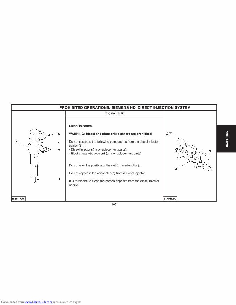
107
INJE
CT
ION
PROHIBITED OPERATIONS: SIEMENS HDI DIRECT INJECTION SYSTEMEngine : 8HX
Diesel injectors.
WARNING: Diesel and ultrasonic cleaners are prohibited.
Do not separate the following components from the diesel injectorcarrier (2) :- Diesel injector (f) (no replacement parts).- Electromagnetic element (c) (no replacement parts).
Do not alter the position of the nut (d) (malfunction).
Do not separate the connector (e) from a diesel injector.
It is forbidden to clean the carbon deposits from the diesel injectornozzle.
B1HP1KAC B1HP1KBC
Downloaded from www.Manualslib.com manuals search engine
108
INJE
CT
ION
SAFETY REQUIREMENTS : HDi DIRECT INJECTION SYSTEMEngine : 8HX
SAFETY REQUIREMENTSPreamble.All interventions on the injection system must be carried out to conform with the following requirements and regulations :- Competent health authorities.- Accident prevention.- Environmental protection.WARNING : Repairs must be carried out by specialised personnel informed of the safety requirements and of the precautions to be taken.
Safety requirements.IMPERATIVE : Take into account the very high pressures in the high pressure fuel circuit (1350 bars), and respect the requirements below :- No smoking in proximity to the high pressure circuit when work is being carried out.- Avoid working close to flame or sparks.Engine running : - Do not work on the high pressure fuel circuit.- Always stay clear of the trajectory of any possible jet of fuel, which could cause serious injuries.- Do not place your hand close to any leak in the high pressure fuel circuit.After the engine has stopped, wait 30 seconds before any intervention.NOTE : This waiting time is necessary in order to allow the high pressure fuel circuit to return to atmospheric pressure.
Downloaded from www.Manualslib.com manuals search engine
109
INJE
CT
ION
SAFETY REQUIREMENTS : HDi DIRECT INJECTION SYSTEMEngine : 8HX
CLEANLINESS REQUIREMENTS.Preliminary operations
IMPERATIVE : The technician should wear clean overalls.Before working on the injection system, it may be necessary to clean the apertures of the following sensitive components :(refer to corresponding procedures).- Fuel filter.- High pressure fuel pump.- Third piston deactivator.- High pressure regulator.- High pressure sensor.- High pressure fuel injection common rail.- High pressure fuel pipes - Diesel injector carriers.
IMPERATIVE : After dismantling, immediately block the apertures of the sensitive components with plugs, to avoid the entry of impurities.Work area.- The work area must be clean and free of clutter.- Components being worked on must be protected from dust contamination.
Downloaded from www.Manualslib.com manuals search engine

110
INJE
CT
ION
CHECKS : LOW PRESSURE FUEL SUPPLY CIRCUITEngine : 8HX
TOOLS[1] Ø 10 mm low pressure connector : 4215-T.[2] Pressure gauge for testing boost pressure : 4073-T.A Toolkit 4073-T
IMPERATIVE : Respect the safety and cleanliness specific to high pressure dieselinjection engines.
Link tools [1] and [2] in series between the fuel high pressure pump and the fuel filter.
ESSENTIAL : Check that the tool [2] is clean.
Check the negative pressure according to the table below:
Vacuum Observations
10 ± 5 cmHg Engine driven by the starter motor
20 ± 5 cmHg
60 ± 5 cmHg
Engine running under full load
Supply circuit obstructed (full tankstrainer, piping, fuel filter).
B1BP2NWC
Downloaded from www.Manualslib.com manuals search engine

111
INJE
CT
ION
AIR SUPPLY CIRCUIT SPECIFICATION
Upper integrated air inlet distributor.
The upper integrated air inlet system is composed of the following ele-ments:
(1) Air filter cover.
(2) Air filter chamber.
(3) Flowmeter
(4) Turbocharger inlet.
(5) Resonator.
(6) Turbocharger outlet.
B1HP1JMP
Engine : 8HX
Downloaded from www.Manualslib.com manuals search engine

112
INJE
CT
ION
AIR SUPPLY CIRCUIT SPECIFICATION
Lower integrated air inlet distributor.
The lower integrated air inlet system is composed of the following ele-ments:
(7) Top EGR pipe.
(8) Inlet manifold.
(9) Diesel fuel filter with reheater and water detector (according to country).
(10) Diesel fuel filter support.
(11) Oil trap.
(12) Oil filler cap.
B1HP1JND
Engine : 8HX
Downloaded from www.Manualslib.com manuals search engine
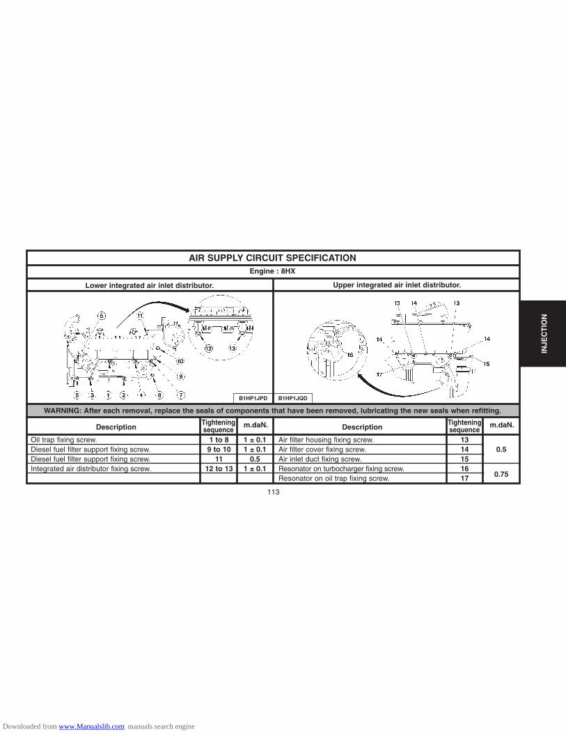
AIR SUPPLY CIRCUIT SPECIFICATIONEngine : 8HX
WARNING: After each removal, replace the seals of components that have been removed, lubricating the new seals when refitting.
Lower integrated air inlet distributor. Upper integrated air inlet distributor.
Oil trap fixing screw.Diesel fuel filter support fixing screw.Diesel fuel filter support fixing screw.Integrated air distributor fixing screw.
1 to 89 to 10
1112 to 13
1 ± 0.11 ± 0.1
0.51 ± 0.1
1314151617
0.5
0.75
DescriptionTighteningsequence
m.daN.
Air filter housing fixing screw.Air filter cover fixing screw.Air inlet duct fixing screw.Resonator on turbocharger fixing screw.Resonator on oil trap fixing screw.
DescriptionTighteningsequence
m.daN.
B1HP1JPD B1HP1JQD
113
INJE
CT
ION
Downloaded from www.Manualslib.com manuals search engine

114
INJE
CT
ION
AIR SUPPLY CIRCUIT SPECIFICATION
(1) Air filter assembly.
(2) Oil trap.
(3) Turbocharger resonance attenuator.
(4) Turbocharger.
(5) Air/air exchanger.
(6) Air distributor.
Air filter : Ref : MARK 4.Turbocharger : Ref : RHF 3V.(Supplier: «IHI»)
B1HP1JGP
Engine : 8HX
Downloaded from www.Manualslib.com manuals search engine

115
INJE
CT
ION
CHECKS : AIR SUPPLY CIRCUIT
Tools.
[1] Manual pressure-vacuum pump FACOM DA 16.
Vacuum pump :
Connect the tool [1] onto the vacuum pump (1).
Start the engine.
Wait 30 seconds.
The vacuum value should be 0.9 ± 0.1 bar at idle.
NOTE : Depollution EURO 4 : The exhaust gas recycling valve is notlinked to the air supply circuit.The exhaust gas recycling valve is controlled by the engine ECU.
B1HP1K8D
Engine : 8HX
Downloaded from www.Manualslib.com manuals search engine
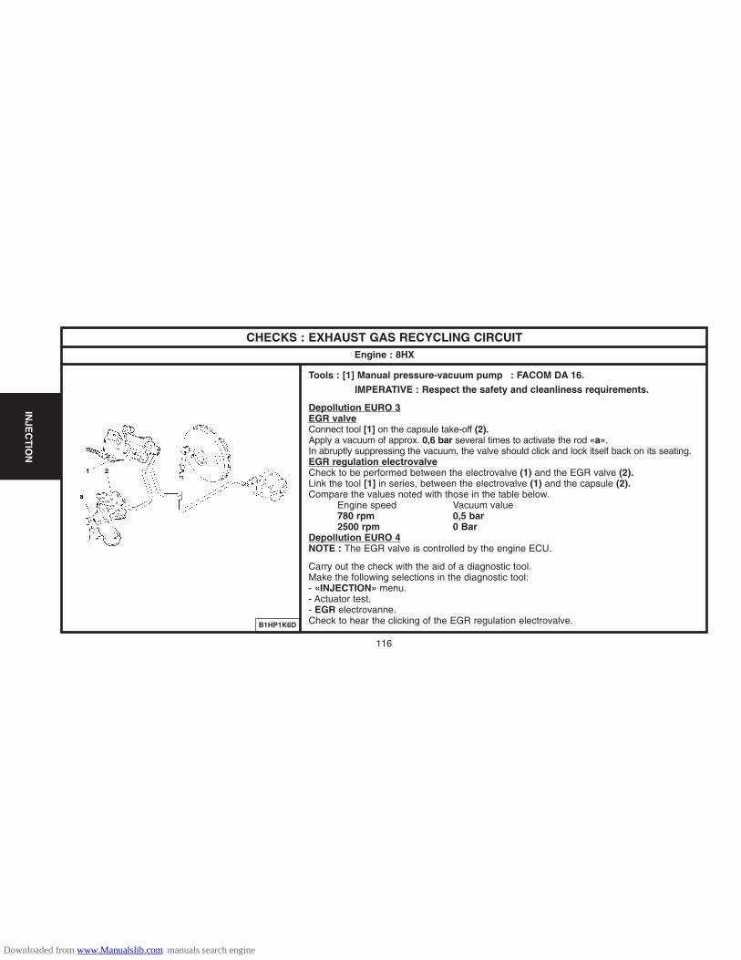
116
INJE
CT
ION
CHECKS : EXHAUST GAS RECYCLING CIRCUITEngine : 8HX
Tools : [1] Manual pressure-vacuum pump : FACOM DA 16.
IMPERATIVE : Respect the safety and cleanliness requirements.
Depollution EURO 3EGR valveConnect tool [1] on the capsule take-off (2).Apply a vacuum of approx. 0,6 bar several times to activate the rod «a».In abruptly suppressing the vacuum, the valve should click and lock itself back on its seating.EGR regulation electrovalveCheck to be performed between the electrovalve (1) and the EGR valve (2).Link the tool [1] in series, between the electrovalve (1) and the capsule (2).Compare the values noted with those in the table below.
Engine speed Vacuum value780 rpm 0,5 bar2500 rpm 0 Bar
Depollution EURO 4NOTE : The EGR valve is controlled by the engine ECU.
Carry out the check with the aid of a diagnostic tool.Make the following selections in the diagnostic tool:- «INJECTION» menu.- Actuator test.- EGR electrovanne.Check to hear the clicking of the EGR regulation electrovalve.B1HP1K6D
Downloaded from www.Manualslib.com manuals search engine

117
INJE
CT
ION
CHECKS : TURBO PRESSUREEngine : 8HX
Tools.[1] Pressure gauge for checking boost pressure : 4073-T.A[2] Sleeve for checking boost pressure : (-).0171.F
ChecksIMPERATIVE : Respect the following test conditions: - Engine at operating temperature.- Vehicle in running order.- Engine under full load.Preparation.Remove the clips (1).Fit the tool [2] in the place of the duct (2).Couple the sleeve [2] on the pressure gauge [1] using the tube «a».Mode of operation.Position tool [1] in the vehicle.Start the engine.Engage first gear, start the vehicle.Engage the gears up to third gear.Decelerate to an engine speed of 1000 rpm.Check the pressure : 0,6 ± 0,05 bar (1500 rpm).Accelerate freely (change from fourth gear to third gear)Check the pressure: 0,9 ± 0,05 bar (between 2500 and 3500 rpm).Remove tools [1], [2] at «a».Reposition the tube (2) and tighten the clips (1).
B1BP2NXD
C5FP0F5C
Downloaded from www.Manualslib.com manuals search engine

118
INJE
CT
ION
FEATURES OF MULTIPOINT INJECTION SYSTEMSummary
(1) Vehicle speed sensor.(2) Catalytic converter.(3) Downstream oxygen sensor.(4) Upstream oxygen sensor.(5) Canister purge electrovalve.(6) Canister reservoir.(7) Fuel pump, fuel filter, gauge, pressure regulator.(8) Injectors.(9) Ignition coil.(10) Thermoswitch – engine coolant thermostat.(11) Engine coolant temperature sensor.(12) Accelerator pedal pressure sensor (KFV–NFU).(13) Butterfly housing.(14) Knock sensor.(15) Engine speed sensor.(16) Inlet air pressure sensor.(17) Diagnostic warning lamp, engine ECU.(18) Ignition injection ECU. (19) Gate valve (HFX-KFV).(20) Air pump (HFX-KFV).
B1HP1TGP
Downloaded from www.Manualslib.com manuals search engine

119
INJE
CT
ION
FEATURES OF MULTIPOINT INJECTION SYSTEMFuel circuit
(diagr.) Component Supplier Reference Observations
5
6
7
8
Fuel
Electrovalve
Fuel tank
Canister reservoir
Pump, gauge and petrol filterassembly
Pressure regulator
Petrol injector
SAGEM
MGI COUTIER
BOSCH
SAGEM(KFV)
BOSCH «EV6»(HFX)
BOSCH(NFU)
Unleaded 95 RON or 98 RON
2-way brown connector – Location : under the frontRH wing.
Capacity : 40 Litres.
2-way black connector – Location : on the side of thefuel tank.
6-way black connector – Voltage: 2 V – Pressure : 3.5 BarsElectric pump submerged in the tank.
Pressure : 3.5 Bars – Fixing : integrated in the fuel pump andgauge assembly.
2-way black connector.Resistance : 14.5 ± 0.05 �
MAGNETIMARELLI
Downloaded from www.Manualslib.com manuals search engine

120
INJE
CT
ION
FEATURES OF MULTIPOINT INJECTION SYSTEMAir inlet circuit
(diagr.) Component Supplier Reference Observations
12
13
16
19
20
Accelerator pedal position sensor(HFX – NFU)
Idle regulation stepper motor (KFX)
Butterfly housing (HFX)
Potentiometer (KFX)
Motorised butterfly housing assembly(KFV)
Butterfly housing (NFU)
Inlet air pressure sensor
Gate valve (HFX – KFV)
Air pump (HFX – KFV)
VD0 2-way connector.
4-way black connector.Fixing : on the butterfly housing
The butterfly housing comprises : butterfly potentiometer, step-per motor3-way black connectorFixing : on the butterfly housing.6-way black connector – Fixing : on the butterfly housing.Tighten to: 0,8 ± 0,1 m.daN – Fixing : on the air inletmanifold.6-way connector.Fixing : on the air inlet manifold.4-way black connectorFixing : on the air inlet manifold..Norm IfL5Fixing of cylinder head : Tighten to 0.8 ± 0.2 m.daNNorm IFL5Fixing on support : Tighten to 0.8 ± 0.2 m.daN
MAGNETIMARELLI
SONCEBOZ
MAGNETIMARELLI
SIEMENSVD0
BOSCH
SAGEM
SAGEM
Downloaded from www.Manualslib.com manuals search engine

121
INJE
CT
ION
FEATURES OF MULTIPOINT INJECTION SYSTEMIgnition circuit
(diagr.) Component Supplier Reference Observations
1
10
11
14
15
18
Vehicle speed sensor
Engine coolant thermoswitch
Engine coolant temperature sensor
Knock sensor
Engine speed sensor
Ignition injection ECU
EATON
DAV
ELECTRIC FIL
BOSCH
ELECTRIC FIL
SIEMENS
MAGNETIMARELLI
48P2 (HFX)
SAGEM S20000PM1 (KFV)
BOSCH ME7 4.4(NFU)
3-way white connectorFixing : on the gearbox differential casing.Fixing : on the cylinder head, alert temperature : 118 °CTighten to : 1.7 ± 0.1 m.daN3-way blue connectorFixing : on the coolant outlet housing.Tighten to : 1.7 ± 0.3 m.daN2-way black connectorFixing : on the rear part of the engine block.IMPERATIVE : Respect the tightening torque ± 0.1 m.daN2-way black connectorFixing : on the clutch housing.IMPERATIVE : Respect the tightening torque 2 ± 0.1 m.daN
«Flash» type Eprom(Reprogrammable Eprom)
Downloaded from www.Manualslib.com manuals search engine

122
INJE
CT
ION
FEATURES OF MULTIPOINT INJECTION SYSTEMIgnition circuit
(diagr.) Component Supplier Reference Observations
3
4
9
Sparking plugs
Downstream oxygen sensor
Upstream oxygen sensor
Ignition coils
SAGEM
BOSCH
CHAMPION
SAGEM
ELECTRIC FIL
Electrode gap : 0.9 mmTighten to : 3 m.daN
4-way blue connectorLocation : on the exhaust manifoldTighten to : 4.7 ± 0.7 m.daN
4-way green connectorLocation : on the exhaust manifoldTighten to : 4.7 ± 0.7 m.daN
4-way grey connector
Downloaded from www.Manualslib.com manuals search engine

123
INJE
CT
ION
FEATURES OF SIEMENS HDI DIRECT INJECTION SYSTEMSummary
B1HP1JFP
Downloaded from www.Manualslib.com manuals search engine
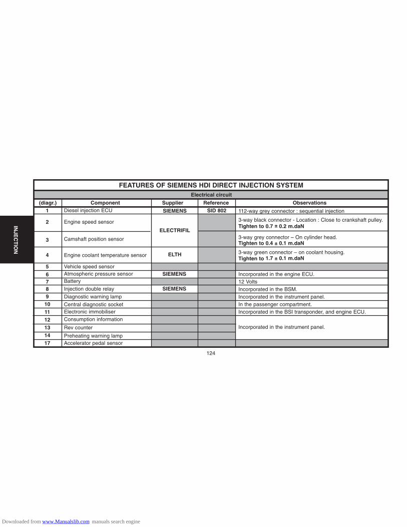
124
INJE
CT
ION
FEATURES OF SIEMENS HDI DIRECT INJECTION SYSTEM
(diagr.) Component Supplier Reference Observations1
2
3
4
5
6789101112131417
Diesel injection ECU
Engine speed sensor
Camshaft position sensor
Engine coolant temperature sensor
Vehicle speed sensorAtmospheric pressure sensorBattery
Injection double relay
Diagnostic warning lamp
Central diagnostic socketElectronic immobiliserConsumption information
Rev counter
Preheating warning lampAccelerator pedal sensor
SIEMENS
ELECTRIFIL
ELTH
SIEMENS
SIEMENS
SID 802 112-way grey connector : sequential injection
3-way black connector - Location : Close to crankshaft pulley.Tighten to 0.7 ± 0.2 m.daN
3-way grey connector – On cylinder head.Tighten to 0.4 ± 0.1 m.daN
3-way green connector – on coolant housing.Tighten to 1.7 ± 0.1 m.daN
Incorporated in the engine ECU.12 VoltsIncorporated in the BSM.Incorporated in the instrument panel.In the passenger compartment.Incorporated in the BSI transponder, and engine ECU.
Incorporated in the instrument panel.
Electrical circuit
Downloaded from www.Manualslib.com manuals search engine
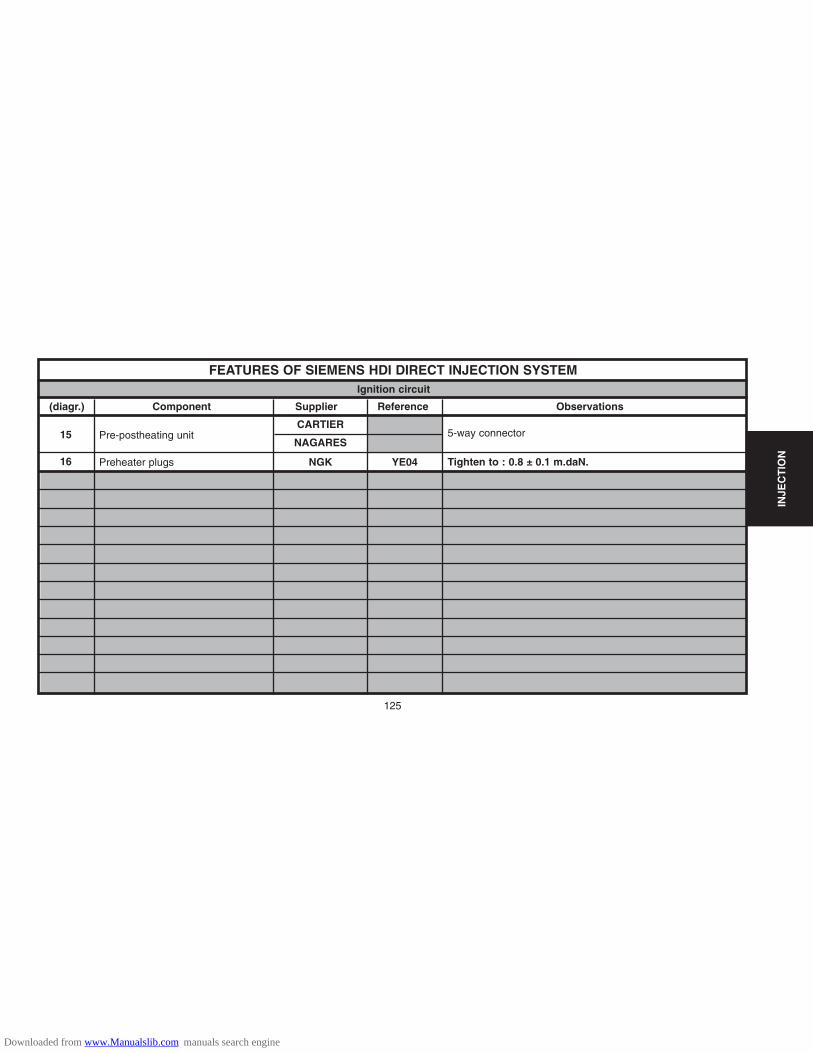
125
INJE
CT
ION
FEATURES OF SIEMENS HDI DIRECT INJECTION SYSTEM
(diagr.) Component Supplier Reference Observations
15
16
Pre-postheating unit
Preheater plugs
CARTIER
NAGARES
NGK YE04
5-way connector
Tighten to : 0.8 ± 0.1 m.daN.
Ignition circuit
Downloaded from www.Manualslib.com manuals search engine
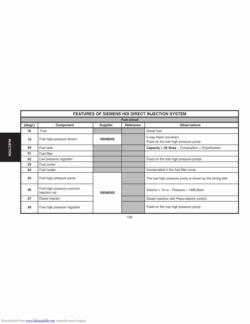
126
INJE
CT
ION
FEATURES OF SIEMENS HDI DIRECT INJECTION SYSTEM
(diagr.) Component Supplier Reference Observations
18
19
20
21
22
23
24
25
26
27
28
Fuel
Fuel high pressure sensor
Fuel tank
Fuel filter
Low pressure regulator
Fuel cooler
Fuel heater
Fuel high pressure pump
Fuel high pressure commoninjection rail
Diesel injector
Fuel high pressure regulator
SIEMENS
SIEMENS
Diesel fuel
5-way black connectorFixed on the fuel high pressure pump
Capacity = 45 litres – Composition = Polyethylene.
Fixed on the fuel high pressure pumpt
Incorporated in the fuel filter cover
The fuel high pressure pump is driven by the timing belt.
Volume = 14 cc - Pressure = 1800 Bars
Diesel injectors with Piezo-electric control
Fixed on the fuel high pressure pump
Fuel circuit
Downloaded from www.Manualslib.com manuals search engine

127
INJE
CT
ION
FEATURES OF SIEMENS HDI DIRECT INJECTION SYSTEM
(diagr.) Component Supplier Reference Observations
29
30
31
32
33
34
35
Air flowmeter
Air filter
Turbocharger
Exhaust gas recycling (EGR) valve
EGR recycling regulation electrovalve
Exhaust line
Vacuum pump
SIEMENS 39071LS.F
50557LLP.A
Type KP35
Type2580132-A
MECAPLAST
KKK
SAGEM
PIEBURG
PIEBURG
Incorporated in the inlet manifold
Air circuit
Downloaded from www.Manualslib.com manuals search engine

128
IGN
ITIO
N
1.1i HFXFR7DE RC8YCL
1.4i KFV RFN58LZ 0.9 mm 2.5 mda.N
1.6i 16v NFU FR7ME
SPARKING PLUGS
Vehicles – Models BOSCHEnginetype
CHAMPION SAGEMElectrode
gapTightening
torque
C2
Downloaded from www.Manualslib.com manuals search engine

129
CL
UT
CH
GE
AR
BO
XD
RIV
ES
HA
FT
S
CLUTCH SPECIFICATION
Engine type
Gearbox type Supplier
Mechanism / type
Engine type
Bearing supplier / height
Clutch disc
Ø of lining. Ext/Int
Quality of lining
1.1i 1.4i 1.6i 16V 1.4 HDi
HFX KFV NFU 8HX
BVM BVM/BVMP (*) BVM/BVMP (*) BVM/BVMP (*)
MA 5/S MA 5 N/L MA 5 S/L MA 5/0
VALEO LUK
180 CP0 3400 200 P 3900
SKF 17 mm
11 R 10 ? ?
180/127 200/134
408
(*) : BVM = Manual gearbox.
: BVMP = Piloted manual gearbox.
Downloaded from www.Manualslib.com manuals search engine

CLUTCH SPECIFICATION
NOTE : All the clutches are «push» type with hydraulic control.
Description.
The declutch control has a declutch fork mounted on a ball-joint.(1) The ball-joint is screwed into the clutch casing.(2) Declutch fork.(3) Clutch casing.(4) Bearing.(5) Clutch plate.
The clutch control slave cylinder (7) is fixed by two screws (6) onto the exterior of the clutch casing.It has a bleed screw (8).
Tightening torques (m.daN).
- Fixing of clutch plate/engine flywheel : 1.2 ± 0.2 (HFX -KFV) 2 ± 0.2 (NFU)- Fixing of engine flywheel/crankshaft
Pre-tightening : 1.7 ± 0.1Angular tightening : 70° ± 5°
B2BP047C B2BP04QC
CL
UT
CH
GE
AR
BO
XD
RIV
ES
HA
FT
S
130
CL
UT
CH
GE
AR
BO
XD
RIV
ES
HA
FT
S
Downloaded from www.Manualslib.com manuals search engine
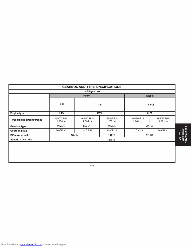
CL
UT
CH
GE
AR
BO
XD
RIV
ES
HA
FT
S
165/70 R14 165/70 R14 185/55 R14 165/70 R14 185/55 R151.804 m 1.804 m 1.781 m 1.804 m 1.781 m
MA 5/S MA 5/N MA 5/L MA 5/0
20 CF 20 20 CF 25 20 CF 16 20 CN 33 20 CN 51
16x65 14X60 17X61
21x18
GEARBOX AND TYRE SPECIFICATIONS
Engine type
Tyres-Rolling circumference
Gearbox type
Gearbox plate
Differential ratio
Speedo drive ratio
1.4 HDi1.1i 1.4i
Petrol Diesel
MA5 gearbox
HFX KFV 8HX
131
Downloaded from www.Manualslib.com manuals search engine
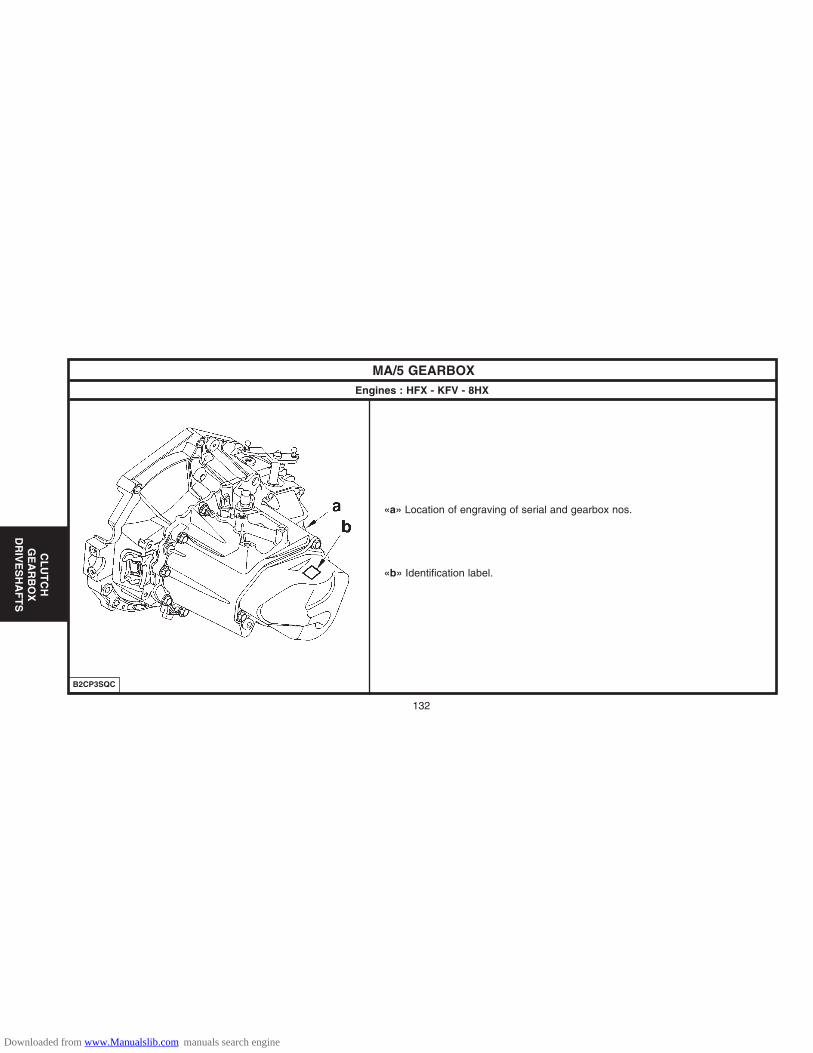
CL
UT
CH
GE
AR
BO
XD
RIV
ES
HA
FT
S
132
MA/5 GEARBOXEngines : HFX - KFV - 8HX
«a» Location of engraving of serial and gearbox nos.
«b» Identification label.
B2CP3SQC
Downloaded from www.Manualslib.com manuals search engine

133
CL
UT
CH
GE
AR
BO
XD
RIV
ES
HA
FT
S
MA/5 GEARBOXEngines : HFX - KFV - 8HX
(1) Circlip(2).Secondary shaft(3) Drive pinion (5th gear)(4) Bearing stop screw(5) Gearbox casing(6) Intermediate plate(7) Gearbox casing fixing screw(8) Clutch bearing guide screw(9) Clutch housing(10) Bearing guide(11) Primary shaft(12) Differential housing(13) Speedometer screw(14) Counter drive(15) Planet pinions(16) Satellite pinions(17) Differential gearwheel(18) Driven pinion (1st gear)(19) 1st / 2nd gear synchroniser and reverse gear driven pinion.(20) Driven pinion (2nd gear).(21) Driven pinion (3rd gear).(22) 3rd and 4th gear synchroniser
B2CP3SRP
Downloaded from www.Manualslib.com manuals search engine
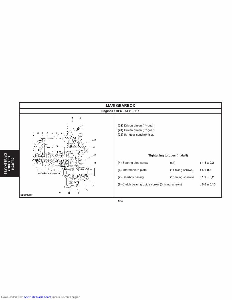
134
CL
UT
CH
GE
AR
BO
XD
RIV
ES
HA
FT
S
MA/5 GEARBOXEngines : HFX - KFV - 8HX
(23) Driven pinion (4th gear).
(24) Driven pinion (5th gear).
(25) 5th gear synchroniser.
Tightening torques (m.daN)
(4) Bearing stop screw (x4) : 1,8 ± 0,2
(6) Intermediate plate (11 fixing screws) : 5 ± 0,5
(7) Gearbox casing (15 fixing screws) : 1,9 ± 0,2
(8) Clutch bearing guide screw (3 fixing screws) : 0,6 ± 0,15
B2CP3SRP
Downloaded from www.Manualslib.com manuals search engine

CL
UT
CH
GE
AR
BO
XD
RIV
ES
HA
FT
S
MA/5 GEARBOXEngines : HFX - KFV - 8HX
Tightening torques (m.daN)
(26) 5th gear cover fixing screw (3 screws) : 2,2 ± 0,2(27) Reverse gear switch (1 screw) : 2,5 ± 0,5(28) Drain plug (1 screw) : 3,3 ± 0,3(29) Level plug (1 screw) : 3,3 ± 0,3
Features.
This gearbox : Has no adjustment.Includes a reverse gear braking device (5th gear synchroniser).Incorporates a device for prohibiting change from 5th gear to reverse gear.The declutch control has a balljoint-mounted declutch fork.
Lubrication.
Oil capacity : 2 ± 0,15 litres.Oil level check : No oil level check (*)Lubrication intervals : Lubricated «for life».
(*) = Only a visual check of the sealing at each engine oil change interval.B2CP3SSD
135
Downloaded from www.Manualslib.com manuals search engine
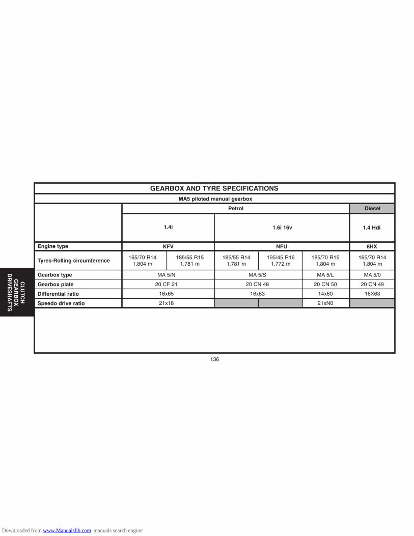
CL
UT
CH
GE
AR
BO
XD
RIV
ES
HA
FT
S
136
165/70 R14 185/55 R15 185/55 R14 195/45 R16 185/70 R15 165/70 R141.804 m 1.781 m 1.781 m 1.772 m 1.804 m 1.804 m
MA 5/N MA 5/S MA 5/L MA 5/0
20 CF 21 20 CN 48 20 CN 50 20 CN 49
16x65 16x63 14x60 16X63
21x18 21xN0
GEARBOX AND TYRE SPECIFICATIONS
Engine type
Tyres-Rolling circumference
Gearbox type
Gearbox plate
Differential ratio
Speedo drive ratio
1.4 Hdi1.6i 16v1.4i
Petrol Diesel
MA5 piloted manual gearbox
KFV 8HXNFU
Downloaded from www.Manualslib.com manuals search engine
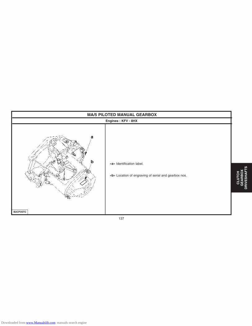
CL
UT
CH
GE
AR
BO
XD
RIV
ES
HA
FT
S
137
MA/5 PILOTED MANUAL GEARBOXEngines : KFV - 8HX
«a» Identification label.
«b» Location of engraving of serial and gearbox nos.
B2CP3STC
Downloaded from www.Manualslib.com manuals search engine

CL
UT
CH
GE
AR
BO
XD
RIV
ES
HA
FT
S
138
MA/5 PILOTED MANUAL GEARBOXEngines : KFV - 8HX
(1) Circlip(2) Secondary shaft(3) Drive pinion (5th gear)(4) Bearing stop screw(5) Gearbox casing(6) Intermediate plate(7) Gearbox casing fixing screw(8) Clutch bearing guide screw(9) Clutch housing(10) Bearing guide(11) Primary shaft(12) Differential housing(13) Speedometer screw(14) Counter drive(15) Planet pinions(16) Satellite pinions(17) Differential gearwheel(18) Driven pinion (1st gear)(19) 1st / 2nd gear synchroniser and reverse gear driven pinion.(20) Driven pinion (2nd gear).(21) Driven pinion (3rd gear).(22) 3rd and 4th gear synchroniser.B2CP3SRP
Downloaded from www.Manualslib.com manuals search engine

139
CL
UT
CH
GE
AR
BO
XD
RIV
ES
HA
FT
S
MA/5 PILOTED MANUAL GEARBOXEngines : KFV - 8HX
(23) Driven pinion (4th gear).(24) Driven pinion (5th gear).(25) 5th gear synchroniser
Tightening torques (m.daN)
(4) Bearing stop screw (x4) : 1.8 ± 0.2
(6) Intermediate plate (11 fixing screws) : 5 ± 0.5
(7) Gearbox casing (15 fixing screws) : 1.9 ± 0.2
(8) Clutch bearing guide screw (3 fixing screws) : 0.6 ± 0.15
B2CP3SRP
Downloaded from www.Manualslib.com manuals search engine

140
CL
UT
CH
GE
AR
BO
XD
RIV
ES
HA
FT
S
MA/5 PILOTED MANUAL GEARBOXEngines : KFV - 8HX
Tightening torques (m.daN)
(26) 5th gear cover fixing screw (3 screws) : 2,2 ± 0,2
(27) Gearbox input speed sensor (1 screw) : 0,8 ± 0,2
(28) Reverse gear switch (1 screw) : 2,5 ± 0,5
(29) Drain plug (1 screw) : 3,3 ± 0,3
(30) Level plug (1 screw) : 3,3 ± 0,3
B2CP3SUD
Downloaded from www.Manualslib.com manuals search engine
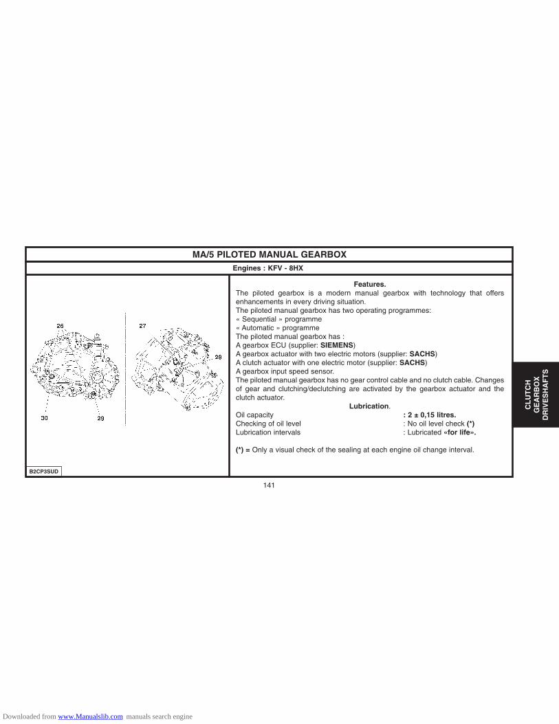
141
CL
UT
CH
GE
AR
BO
XD
RIV
ES
HA
FT
S
MA/5 PILOTED MANUAL GEARBOXEngines : KFV - 8HX
Features.The piloted gearbox is a modern manual gearbox with technology that offersenhancements in every driving situation.The piloted manual gearbox has two operating programmes: « Sequential » programme« Automatic » programmeThe piloted manual gearbox has : A gearbox ECU (supplier: SIEMENS)A gearbox actuator with two electric motors (supplier: SACHS)A clutch actuator with one electric motor (supplier: SACHS)A gearbox input speed sensor.The piloted manual gearbox has no gear control cable and no clutch cable. Changesof gear and clutching/declutching are activated by the gearbox actuator and theclutch actuator.
Lubrication.Oil capacity : 2 ± 0,15 litres.Checking of oil level : No oil level check (*)Lubrication intervals : Lubricated «for life».
(*) = Only a visual check of the sealing at each engine oil change interval.
B2CP3SUD
Downloaded from www.Manualslib.com manuals search engine

CL
UT
CH
GE
AR
BO
XD
RIV
ES
HA
FT
S
142
RECOMMENDATIONS - PRECAUTIONS : MA TYPE PILOTED MANUAL GEARBOX
Safety requirements
ESSENTIAL : Given the special features of the MA type pilotedmanual gearbox, observe the requirements detailed below.
IMPERATIVE : Always disconnect the battery negative terminalbefore operating on the actuators.
NOTE : After disconnecting the battery, never try to remove the clutchactuator on the vehicle before having checked that it is in the closedposition.(rod pushed in).
IMPERATIVE : After Sales checks done with the engine running mustbe performed with «Neutral» engaged and the handbrake on (unlessthere is a clear mention otherwise in the repair procedures)
IMPERATIVE : The areas of movement of the clutch fork and of thegear engagement lever must always be kept free during the actuatoroperating phases.
IMPERATIVE : When initialising the clutch actuator and/or gearboxactuator, do not allow any person to walk or stand in front of thevehicle.
WARNING : When the engine is running, it is forbidden to performrepairs on the clutch and gearbox actuators on the vehicle (whethermanually or using a diagnostic tool).
WARNING : Each time the driver’s door is opened and each time theigntion is switched on, the gearbox ECU prompts the initialising of theclutch and gearbox actuators (there is movement of the clutch fork andof the gear lever).
WARNING : Whether the ignition is switched on or not, an action onthe gear selector causes the clutch to move and the gear engagementlever to move on the gearbox.
Downloaded from www.Manualslib.com manuals search engine

143
CL
UT
CH
GE
AR
BO
XD
RIV
ES
HA
FT
S
RECOMMENDATIONS - PRECAUTIONS : MA TYPE PILOTED MANUAL GEARBOX
Operations on electrical components :Do not disconnect : The battery when the engine is running.The ECU with the ignition switched on.The clutch and gearbox actuators with the ignition switched on.
When carrying out electrical checks : The battery must be correctly charged.Never use a voltage source higher than 16V.Never use a lamp to supply an actuator directly.
Befor disconnecting connector, check : The condition of the various contacts (for deformation, corrosion etc.)The presence and the status of the mechanical unlocking.
Driving the vehicle.
IMPERATIVE : Never move the vehicle with the ignition switched off.
Never push the vehicle to attempt to start it (impossible with a pilotedmanual gearbox.
Towing.
Conditions for towing.
It is necessary to lift the front of the vehicle to tow it, after havingpositioned the gear lever in neutral. If there is a gearbox fault ormalfunction, the vehicle can remain immobilised depending on theseriousness of the fault.
If a gear is engaged, the conditions for immobilisation of thevehicle are : Combustion engine stopped (the engine should not be started).The clutch is open (clutched).
In these conditions are met, you can lift the front of the vehicle to tow it.
If it should not be possibe to lift the front of the vehicle, there areways to unblock it :
Engage «N», using a diagnostic tool.Engage «N», without using a diagnostic tool.
Downloaded from www.Manualslib.com manuals search engine

144
CL
UT
CH
GE
AR
BO
XD
RIV
ES
HA
FT
S
RECOMMENDATIONS - PRECAUTIONS : MA TYPE PILOTED MANUAL GEARBOX
Engaging of «N», à using a diagnostic tool.
Preliminary operations: Battery voltage higher than 12,5 volts.Ignition switched on.Connect the diagnostic tool to the vehicle’s diagnostic socket.
From the diagnostic tool menus, select :
«DIAGNOSIS»MA type piloted manual gearbox.Actuator test.Gearbox actuator test.Gear engagement test.N (neutral)
NOTE : The letter «N» should appear on the instrument panel.If not, see the following solution: Engaging of «N», without using a diagnostic tool.
Engaging of «N», without using a diagnostic tool.
In this configuration, the gearbox actuator is blocked, gear engaged.
NOTE : This recovery solution is to be used solely in a case where theattempt to make the gearbox actuator engage «N» via the diagnostictool has failed.
Downloaded from www.Manualslib.com manuals search engine

145
CL
UT
CH
GE
AR
BO
XD
RIV
ES
HA
FT
S
RECOMMENDATIONS - PRECAUTIONS : MA TYPE PILOTED MANUAL GEARBOX
Engaging of «N», without using a diagnostic tool (continued).
Preliminary operation:
Disconnect the battery negative terminal.
Remove the air filter.
Use a 22 mm spanner.
Use the spanner to lift the gear engagement lever the maximum possible until theaxis «A» of the engagement lever is perpendicular to the axis «B» (mid point ofthe gear engagement lever).
When this position is attained, position «N» is engaged.
B2CP3L8D
Downloaded from www.Manualslib.com manuals search engine

CL
UT
CH
GE
AR
BO
XD
RIV
ES
HA
FT
S
146
MA/5 GEARBOX CONTROLSEngines : HFX - KFV - NFU - 8HX
(1) Gear control lever.
(2) Gear engagement control cable (*)
(3) Gear selection control cable (*)
(*) The two cables cannot be separated.
B2CP3HXD
Downloaded from www.Manualslib.com manuals search engine

CL
UT
CH
GE
AR
BO
XD
RIV
ES
HA
FT
S
MA/5 GEARBOX CONTROLSEngines : HFX - KFV - NFU - 8HX
(4) Gear engagement ball-joint Ø 10 mm.
(5) Gear selection ball-joint Ø 10 mm.
Length D Length C
Gear engagement control 1040 mm 815 mmcable (2)
Length A Length B
Gear selection control 1149 mm 800 mmcable (3)B2CP3HZD
B2CP3HYC
147
Downloaded from www.Manualslib.com manuals search engine

CL
UT
CH
GE
AR
BO
XD
RIV
ES
HA
FT
S
148
MA/5 GEARBOX CONTROLSEngines : HFX - KFV - NFU - 8HX
Adjustment.
WARNING: Do not use any tool to detach theball-joints.
The gear selection control and gear engagement controlcables cannot be adjusted.
To unlock the ball-joint, press at «a» then pull theball-joint upwards.
To release the sleeve stops, pull the needles «b», in thedirection of the arrow, then disengage the sleeve stopsfrom their supports.
B2CP3J1D
B2CP3J0D
Downloaded from www.Manualslib.com manuals search engine

149
CL
UT
CH
GE
AR
BO
XD
RIV
ES
HA
FT
S
NONE
DRIVESHAFTS - GEARBOX
Tightening torques (m.daN)
Driveshaftbearing
EnginesVehicles Gearbox RH side LH side Tool kit
Gearbox oil seal mandrels
24.5 ± 0.5 7114-T.X 7114-T.W 7116-T
Driveshaftnut
HFX - KFV8HX
NFU
MA/5C22 ± 0.2
Tightening torques for wheel bolts (m.daN)
CITROËN C2Steel
Aluminium9 ± 0.1
Downloaded from www.Manualslib.com manuals search engine

WHEELS AND TYRESStandard fitting
Spare wheelWheelsTrims
Trim levelsEngines
1.1i
1.1i
1.6i 16V
A - X
165/70 R14 81 T XT11.804 m
185/55 R15 82 H XH11.781 m
195/45 R16 80V1.772 m
PRIMACY/SPORT
5.5J 14 H2 4.24MILAN
5.5J 14 H2 4.24CONDOR
5.5J 14 H2 4.24MILAN
5.5J 14 H2 4.24CONDOR
6J 15 4.27PELICAN
6J 16 4.27LEOPARD
SX - SX - Pack
A - X
SX - SX - Pack
VTR
VTR - VTS
Tyres(Circumference) WheelsTyres
150
AX
LE
SS
US
PE
NS
ION
ST
EE
RIN
G
165/70 R14 81 T XT1 5.5J 14 H2 4.24
6J 15 4.27
6J 16 4.27
185/55 R15 84 H
195/45 R16 80V
(1) = Normal operating pressure (Max. 4 persons and 40 kg in boot).
Downloaded from www.Manualslib.com manuals search engine

151
AX
LE
SS
US
PE
NS
ION
ST
EE
RIN
G
WHEELS AND TYRESStandard fitting
Spare wheelWheelsTrims
Trim levelsEngines
1.4 HDi
A - X165/70 R14 81 T XT1
1.804 m
185/55 R15 82 H XH11.781 m
5.5J 14 H2 4.24MILAN
5.5J 14 H2 4.24CONDOR
6J 16 4.27
SX - SX - Pack
VTR
Tyres(Circumference) WheelsTyres
165/70 R14 81 T XT1
185/55 R15 82 H
5.5J 14 H2 4.24
6J 15 4.27
(1) = Normal operating pressure (Max. 4 persons and 40 kg in boot).
Downloaded from www.Manualslib.com manuals search engine
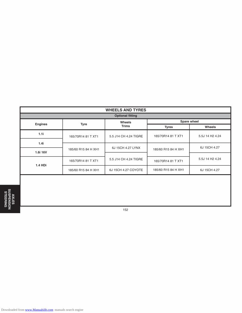
152
AX
LE
SS
US
PE
NS
ION
ST
EE
RIN
G
WHEELS AND TYRESOptional fitting
Spare wheelTyreEngines
1.1i
1.4i
1.6i 16V
1.4 HDi
165/70R14 81 T XT1
185/60 R15 84 H XH1
165/70R14 81 T XT1
185/60 R15 84 H XH1
5.5 J14 CH 4.24 TIGRE
6J 15CH 4.27 LYNX
5.5 J14 CH 4.24 TIGRE
6J 15CH 4.27 COYOTE
165/70R14 81 T XT1
185/60 R15 84 H XH1
165/70R14 81 T XT1
185/60 R15 84 H XH1
WheelsTrims WheelsTyres
5.5J 14 H2 4.24
6J 15CH 4.27
5.5J 14 H2 4.24
6J 15CH 4.27
Downloaded from www.Manualslib.com manuals search engine

WHEELS AND TYRESTyre pressures, vehicle empty
Tyre pressures, vehicle under load
Pressure (Bars)
Pressure (Bars)
Front
2.1 2.1
2.3 2.8
2.4
2.1
2.4
Tyre dimensions
Tyre dimensions
165/70 R14 (81T) XT1
185/55 R15 (84H) XH1
195/45 R16 (80V)
165/70 R14 (81T) XT1
185/55 R15 (84H) XH1
195/45 R16 (80V)
Rear Spare wheel
Front
2.8
2.4
2.82.1
2.4
Rear Spare wheel
153
AX
LE
SS
US
PE
NS
ION
ST
EE
RIN
G
Downloaded from www.Manualslib.com manuals search engine

154
AX
LE
SS
US
PE
NS
ION
ST
EE
RIN
G
WHEELS AND TYRESIdentification of inflation pressures
The label indicating recommended tyre pressures is affixed to theinner panel of one of the front doors.
‘‘a’’: Recommended tyre inflation pressures.(vehicle empty and vehicle under load).
«b»: Type of tyre.
«c»: Recommended inflation pressure for the spare tyre.
B2GP010D
Downloaded from www.Manualslib.com manuals search engine

WHEELS AND TYRESIdentification of wheel bolts
(1) : Wheel bolt.(2) : Light alloy wheel.(3) : Spare wheel.
Steel wheel.
Bolt for wheel with conical contact surface.
Light alloy wheel.
Mixed fixing wheel bolts, permitting the securing of the following wheeltypes:
Light alloy wheel (fixing with flat contact surface).
Steel spare wheel (fixing with tapered contact surface).
Tightening torque:9 ± 1 m.daN.
B2GP00JD
155
AX
LE
SS
US
PE
NS
ION
ST
EE
RIN
G
Downloaded from www.Manualslib.com manuals search engine

156
AX
LE
SS
US
PE
NS
ION
ST
EE
RIN
G
AXLE GEOMETRYConditions for checking and adjusting
Vehicle heights at reference height
Rear heightFront height
L2L1
Tyres inflated to correct pressures. Vehicle at reference height.Steering rack locked at mid point (See corresponding operation).
H1 = R1 - L1
H1 = Measurement between the measuring zone underneath the frontsubframe and the ground.R1 = Front wheel radius under load.L1 = Distance between the wheel axis and the measuring zoneunderneath the front subframe.
H2 = R2 + L2
H2 = Measurement between the measuring zone underneath the rear silland the ground.R2 =Rear wheel radius under load.L2 = Distance between the wheel axis and the measuring zoneunderneath the rear sill.
E1AP0BZD
Downloaded from www.Manualslib.com manuals search engine

AXLE GEOMETRY
Measure the radius of the front wheel R1 - Calculate dimension H1 = R1 – L1
Z1 = Measuring zone underneath the front subframe.
[1] Gauge for measuring the wheel radius, 4 bolts, tool 8006-T
Measuring rear heightMeasuring front height
Z2 = Measuring zone underneath the rear sill.
Measure the radius of the rear wheel R2 - Calculate dimension H2 = R2 + L2
Compress the suspension to obtain the calculated values.The height difference between the two axle dimensions should be less than 10 mm.(*) = CRD : Difficult road conditions.
Value at referenceheight
(+ 6 - 8 mm)
Except CRD (*) Except CRD (*)
L1 = 142.5 mm
HFX - KFV - 8HX
L1 = 152.5 mm
NFUValue at reference
height(+ 10 - 6 mm) L2= 52 mm
HFX - KFV - 8HX
L2= 42 mm
NFU
B3CP07SD
157
AX
LE
SS
US
PE
NS
ION
ST
EE
RIN
G
Downloaded from www.Manualslib.com manuals search engine

AX
LE
SS
US
PE
NS
ION
ST
EE
RIN
G
158
A < B = Positive figure : + = TOE-IN
A > B = Negative figure : - = TOE-OUT
WARNING
AXLE GEOMETRYRear axleFront axle
Dissymmetry of lower camber at 0° 18.Dissymmetry of lower castor at 0° 30’.Dissymmetry of lower camber at 0° 18’Distribute symmetrically, LH / RH wheel, the total tracking value.
All types (except CRD)HFX - KFV - 8HX HFX - KFV - 8HX
NFU NFU
Tracking Camber
Non adjustable
5.5 ± 10°53’ ± 0°09’ - 1°30’
Tracking Camber
Non adjustable
5.8 ± 1
0°49’ ± 0°09’ - 1°31’
AllTypes
mm
0°
AllTypes
mm
0°
B3CP02UC
Pivot angle± 0° 30’
Camber± 0° 30’
Castor± 0° 18’Tracking
Adjustable
2 ± 1
0° 18’±0°09’ 3°58’ - 0°31’ 11°26’
2 ± 1
0° 18’±0°09’ 4° - 0°32’ 11°35’
Non adjustable
Adjustable Non adjustable
Vehicle
Pivot angle± 0° 30’
Camber± 0° 30’
Castor± 0° 18’TrackingVehicle
Downloaded from www.Manualslib.com manuals search engine

FRONT AXLETightening torques (m.daN)
(1) Nut fixing suspension leg on body : 6,5 ± 0,6(2) Damper : (3) Anti-roll bar link rod upper ball-joint : 3,2 ± 0,3(4) Suspension leg pivot : 5,4 ± 0,5(5) Anti-roll bar link rod lower ball-joint : 3,2 ± 0,3(6) Anti-roll bar bearing fixing on subframe : 8 ± 0,8(7) Hub nut : 24,5 ± 0,5(8) Wheel bolt : 9 ± 1(9) Subframe to bodyshell fixing screw : 10 ± 1(10) Anti-roll bar : (11) Pivot lower ball-joint fixing on lower arm : 5,5 ± 0,5(12) Pivot lower ball-joint fixing : 4 ± 0,4(13) Lower arm front and rear mounting fixing : 14 ± 0,4(14) Stabiliser bar screw : 6,6 ± 0,7 (15) Steering ball-joint fixing : 3,5 ± 0,3
B3CP07RP
HFX - KFV 18 VioletNFU 20 Green8HX 19 Blue
Entreprise vehicles Diameter (mm) ColourHFX - 8HX 18 Violet
CRD vehicles Diameter (mm) ColourKFV - 8HX 18 Violet
NFU 20 Green
Anti-roll barColourDiameter (mm)
Private vehicles Europe
159
AX
LE
SS
US
PE
NS
ION
ST
EE
RIN
G
Downloaded from www.Manualslib.com manuals search engine
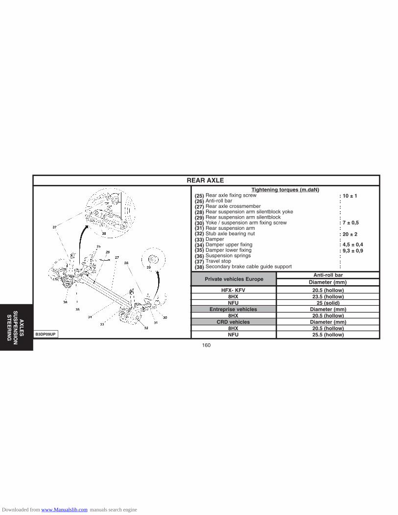
160
AX
LE
SS
US
PE
NS
ION
ST
EE
RIN
G
REAR AXLETightening torques (m.daN)
(25) Rear axle fixing screw : 10 ± 1(26) Anti-roll bar : (27) Rear axle crossmember : (28) Rear suspension arm silentblock yoke : (29) Rear suspension arm silentblock : (30) Yoke / suspension arm fixing screw : 7 ± 0,5(31) Rear suspension arm : (32) Stub axle bearing nut : 20 ± 2(33) Damper : (34) Damper upper fixing : 4,5 ± 0,4(35) Damper lower fixing : 9,3 ± 0,9(36) Suspension springs : (37) Travel stop : (38) Secondary brake cable guide support :
B3DP09UP
Anti-roll barDiameter (mm)Private vehicles Europe
HFX- KFV 20.5 (hollow)8HX 23.5 (hollow)NFU 25 (solid)
Entreprise vehicles Diameter (mm)8HX 20.5 (hollow)
CRD vehicles Diameter (mm)8HX 20.5 (hollow)NFU 25.5 (hollow)
Downloaded from www.Manualslib.com manuals search engine
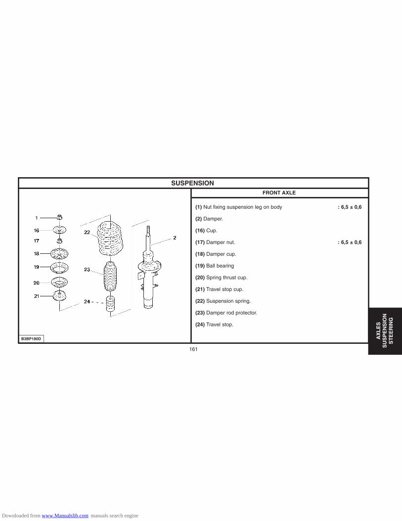
161
AX
LE
SS
US
PE
NS
ION
ST
EE
RIN
G
SUSPENSIONFRONT AXLE
(1) Nut fixing suspension leg on body : 6,5 ± 0,6
(2) Damper.
(16) Cup.
(17) Damper nut. : 6,5 ± 0,6
(18) Damper cup.
(19) Ball bearing
(20) Spring thrust cup.
(21) Travel stop cup.
(22) Suspension spring.
(23) Damper rod protector.
(24) Travel stop.
B3BP180D
Downloaded from www.Manualslib.com manuals search engine

AX
LE
SS
US
PE
NS
ION
ST
EE
RIN
G
162
FEATURES OF ELECTRIC POWER STEERINGEngines : HFX - KFV - NFU - 8HX
Steering column
Tightening torques m.daN.
(1) Steering wheel fixing 2 ± 0,3
(2) Steering column fixing on support 2,2 ± 0,5
(3) Steering cardan fixing 2,2 ± 0,2
Identification
Identified by the colour of the ring at «a».
Left hand drive : BLUE ring.
Right hand drive : WHITE ring.
B3EP13GD B3EP13HC
Downloaded from www.Manualslib.com manuals search engine

AX
LE
SS
US
PE
NS
ION
ST
EE
RIN
G
FEATURES OF ELECTRIC POWER STEERINGEngines : HFX - KFV - NFU - 8HX
Steering mechanism
Tightening torques m.daN
(4) Ball-joint fixing on pivot : 3,5 ± 0,3
(5) Steering rod lock-nut : 5 ± 0,5
(8) Threaded washer
(9) Stud : 0,8 ± 0,1
(10) Flat washers
(11) Fixing of mechanism on subframe : 8 ± 0,8
Connectors.
(6) Supply of electric assistance motor.
(7) Torque sensor signals.
HFX - KFV - 8HX NFU
Electric motor 60 A 65 ASteering rack travel 2x72 2x64Steering ratio 45.6/1
Number of rotations of steering wheel
3.2 2.8
Inner angle of lock 38° 32°30’Outer angle of lock 32°24’ 28°42’
163
B3EP13JD
Downloaded from www.Manualslib.com manuals search engine

AX
LE
SS
US
PE
NS
ION
ST
EE
RIN
G
164
FEATURES OF ELECTRIC POWER STEERINGEngines : HFX - KFV - NFU - 8HX
Electric steering assistance ECUSteering assistance
Supplier: KOYO.
The steering assistance is provided by the assistance motor (12), control-led by the ECU.Power delivered to the assistance motor (12) depends on:
- Speed of the vehicle.
- Torque applied on the steering wheel.
Only one ECU version, whatever the engine-type.The electric power steering ECU is linked to the following connec-tors: - (6) Assistance motor supply.- (13) Electric power steering ECU supply.- (14) Control signals.After changing the electric power steering ECU, it is necessary toperform a configuration.
B3EP13KC B3EP13LC
Downloaded from www.Manualslib.com manuals search engine

AX
LE
SS
US
PE
NS
ION
ST
EE
RIN
G
SPECIAL FEATURES : STEERINGEngines : HFX - KFV - NFU - 8HX
Centring the steering rack
Preliminary operation.
Raise and support the vehicle on a two-column lift.Remove, on the RH side of the steering rack: - Clip (1).- Clip (2).
Release the steering rack protection gaiter.
SettingMove the steering to full left hand lock.Measure the dimension X.Move the steering to full right hand lock.Measure the dimension Y.
Calculate the dimension: L = (Y – X) : 2.
Refit: - The steering rack protection gaiter- New clips (1) and (2).
B3EP13UC
B3EP13VD
165
Downloaded from www.Manualslib.com manuals search engine

166
20.6
203.2
LUCAS .TRW-/-C 48/13-/-48
266
13/110.05
0.01
TEXTAR-/-T 4144
13/3
203/205
38DON-/-8259/1
BRAKE SPECIFICATIONS (WITHOUT ABS)
Master cylinder
Master vac
Caliper/piston makes
Disc Plain
Disc thickness/minimum thickness
Maximum run-out (mm)
Difference in max. thickness on same circumference (mm)
Supplier / Brake pad grade
Original thickness/minimum thickness
Original drum/maximum
Width
Supplier / grade
1.1i 1.4 HDi1.4i
HFX KFV 8HXEngine type
Ø mm
Ømm
FT
RR
BR
AK
ES
Downloaded from www.Manualslib.com manuals search engine
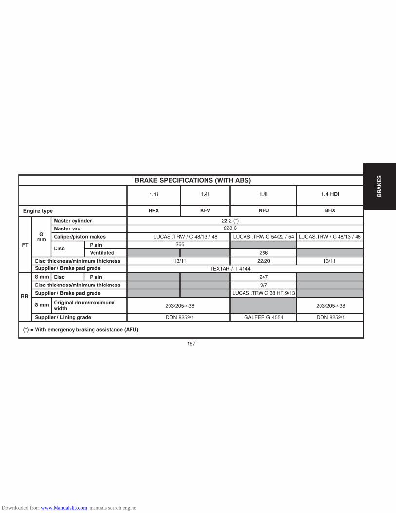
167
BR
AK
ES
22.2 (*)228.6
LUCAS .TRW-/-C 48/13-/-48 LUCAS .TRW C 54/22-/-54 LUCAS.TRW-/-C 48/13-/-48266
266
13/11 22/20 13/11
TEXTAR-/-T 4144
247
9/7
LUCAS .TRW C 38 HR 9/13
203/205-/-38 203/205-/-38
DON 8259/1 GALFER G 4554 DON 8259/1
BRAKE SPECIFICATIONS (WITH ABS)
Master cylinder
Master vac
Caliper/piston makes
DiscPlain
Ventilated
Disc thickness/minimum thicknessSupplier / Brake pad grade
Disc Plain
Disc thickness/minimum thickness
Supplier / Brake pad grade
Original drum/maximum/ width
Supplier / Lining grade
1.1i 1.4 HDi1.4i 1.4i
HFX KFV 8HXNFUEngine type
Ø mm
Ømm
Ø mm
FT
RR
(*) = With emergency braking assistance (AFU)
Downloaded from www.Manualslib.com manuals search engine

BR
AK
ES
168
B3FP7BSD
BRAKE SPECIFICATIONS
Braking circuit without ABS - REF (drum brakes at the rear) Braking system specifications
- Braking circuit at «X».
- Front brakes with ventilated discs (*).
- Rear brakes with eitther drums or discs (*).
- Handbrake lever controlling cables acting on therear wheels.
The compensator and main brake limiter functions areassured by the ABS EBD system.
NOTE : REF = Electronic Brakeforce Distribution
(*) = according to version
Downloaded from www.Manualslib.com manuals search engine

169
BR
AK
ESBRAKE SPECIFICATIONS
Braking circuit with ABS - REF (drum brakes at the rear)
B3FP7BTD
Downloaded from www.Manualslib.com manuals search engine
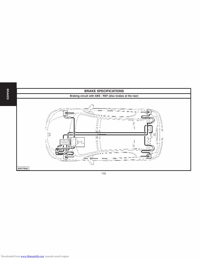
170
BR
AK
ES
BRAKE SPECIFICATIONSBraking circuit with ABS - REF (disc brakes at the rear)
B3FP7BUD
Downloaded from www.Manualslib.com manuals search engine
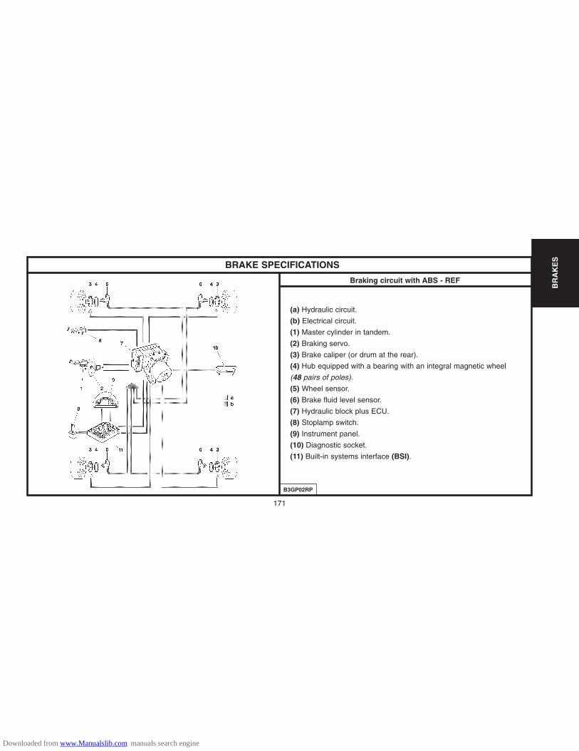
BR
AK
ES
BRAKE SPECIFICATIONS
Braking circuit with ABS - REF
(a) Hydraulic circuit.
(b) Electrical circuit.
(1) Master cylinder in tandem.
(2) Braking servo.
(3) Brake caliper (or drum at the rear).
(4) Hub equipped with a bearing with an integral magnetic wheel
(48 pairs of poles).
(5) Wheel sensor.
(6) Brake fluid level sensor.
(7) Hydraulic block plus ECU.
(8) Stoplamp switch.
(9) Instrument panel.
(10) Diagnostic socket.
(11) Built-in systems interface (BSI).
B3GP02RP
171
Downloaded from www.Manualslib.com manuals search engine

BR
AK
ES
172
BRAKE SPECIFICATIONS
(7) Hydraulic block ElementsRef. Supplier Part No. Observations
B3FP7BVC
Mounted on the front LH chassis member.4 adjustment channels
26-way connector.Integral to the hydraulic block
2-way blue connector.The sensors are inductive-type.Mounted on the pivot.Non-adjustable airgap: 0,16 to 1,6 mm.Tightening torque: 0,8 ± 0,2 m.daN
2-way blue connector.The sensors are inductive-type.Mounted on the suspension arm.Non-adjustable airgap: 0,35 to 1,6 mm.Tightening torque: 0,8 ± 0,2 m.daN
Hub equipped with a bearing with an integralmagnetic wheel (48 pairs of poles).
Hydraulicblock
ECU
Front wheelsensor.
Rear wheelsensor.
Hub bearing. SNR
TEVES
7
5
4
ABS MK 7096 514 120 80
ESP -ABS MK.6096 490 288 80
ABS MK.70
ESP -ABS MK 60
96 387 201 80
Downloaded from www.Manualslib.com manuals search engine

173
BR
AK
ESBRAKE SPECIFICATIONS
Brake pedal gear Front brake Rear brake
(16) Servo fixing 2,2 ± 0,3.
(17) Fixing on master cylinder 2 ± 0,5.(12) Yoke fixing on caliper 10,5± 1
(13) Yoke fixing on caliper 3± 0,3
(14) Rear caliper fixing on arm 5,3±0,5
(15) Yoke fixing on caliper 3,8±0,3
Tightening torques (m.daN).
B3FP166D B3FP164C B3FP165C
Downloaded from www.Manualslib.com manuals search engine

BR
AK
ES
174
C5FP0ELD
HANDBRAKE (Adjustment)
AdjustmentLift and chock the vehicle.
Remove: - The rear cover (8)- The nut (9)- The handbrake trim (6).- The gear lever gaiter (5).- The front cover (3).- The screws (1).
Disconnect the connectors of the following components: - The cigar lighter (2).- The electric window buttons (4).Remove the central console (7).
WARNING: Check that the brake cables are correctlyrouted under the vehicle.
Slacken the handbrake lever.Press gently on the brake pedal (Then repeat theoperation 3 times).Pull vigorously on the handbrake lever 4 or 5 times.
Downloaded from www.Manualslib.com manuals search engine
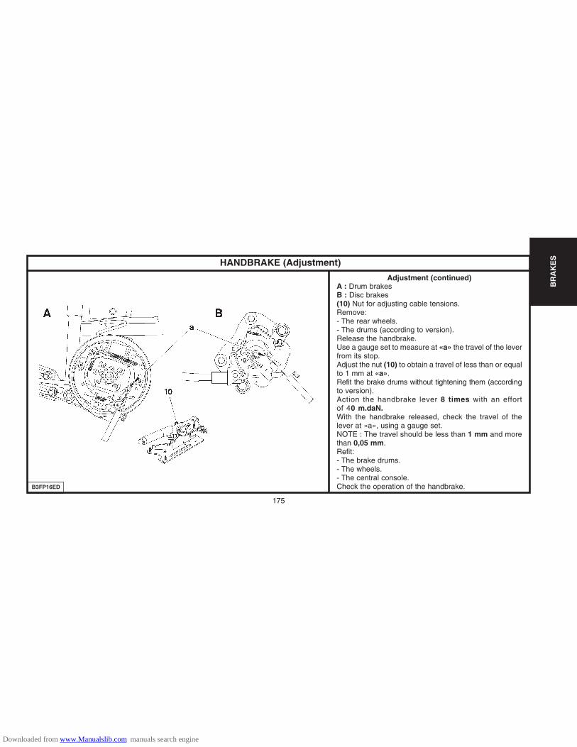
BR
AK
ES
B3FP16ED
HANDBRAKE (Adjustment)
Adjustment (continued)A : Drum brakesB : Disc brakes(10) Nut for adjusting cable tensions.Remove: - The rear wheels.- The drums (according to version).Release the handbrake.Use a gauge set to measure at «a» the travel of the leverfrom its stop.Adjust the nut (10) to obtain a travel of less than or equalto 1 mm at «a».Refit the brake drums without tightening them (accordingto version).Action the handbrake lever 8 times with an effortof 40 m.daN.With the handbrake released, check the travel of thelever at «a», using a gauge set.NOTE : The travel should be less than 1 mm and morethan 0,05 mm.Refit: - The brake drums.- The wheels.- The central console.Check the operation of the handbrake.
175
Downloaded from www.Manualslib.com manuals search engine
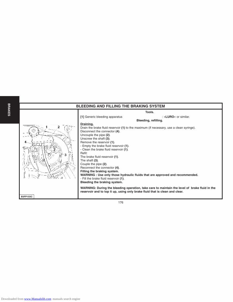
B3FP15XC
BR
AK
ES
176
BLEEDING AND FILLING THE BRAKING SYSTEM
Tools.
[1] Generic bleeding apparatus : «LURO» or similar.Bleeding, refilling.
Draining.Drain the brake fluid reservoir (1) to the maximum (if necessary, use a clean syringe).Disconnect the connector (4).Uncouple the pipe (2).Unscrew the shaft (3).Remove the reservoir (1).- Empty the brake fluid reservoir (1).- Clean the brake fluid reservoir (1).Refit: The brake fluid reservoir (1).The shaft (3).Couple the pipe (2).Reconnect the connector (4).Filling the braking system.WARNING : Use only those hydraulic fluids that are approved and recommended.- Fill the brake fluid reservoir (1).Bleeding the braking system.
WARNING: During the bleeding operation, take care to maintain the level of brake fluid in thereservoir and to top it up, using only brake fluid that is clean and clear.
Downloaded from www.Manualslib.com manuals search engine

BR
AK
ES
177
B3FP15YC B3FP15ZD
BLEEDING AND FILLING THE BRAKING SYSTEM
Bleeding, filling (continued)
Bleeding the primary braking circuit.
WARNING: The ABS should not be active during thebleeding operation.
- Front brake caliper: Bleed screw (5).A : Rear brake caliperB : Rear brake drum
Bleed screw (6).
Bleed each wheel cylinder, proceeding in the followingorder :
Front LH wheel.Front RH wheel.Rear LH wheel.Rear RH wheel.
Downloaded from www.Manualslib.com manuals search engine
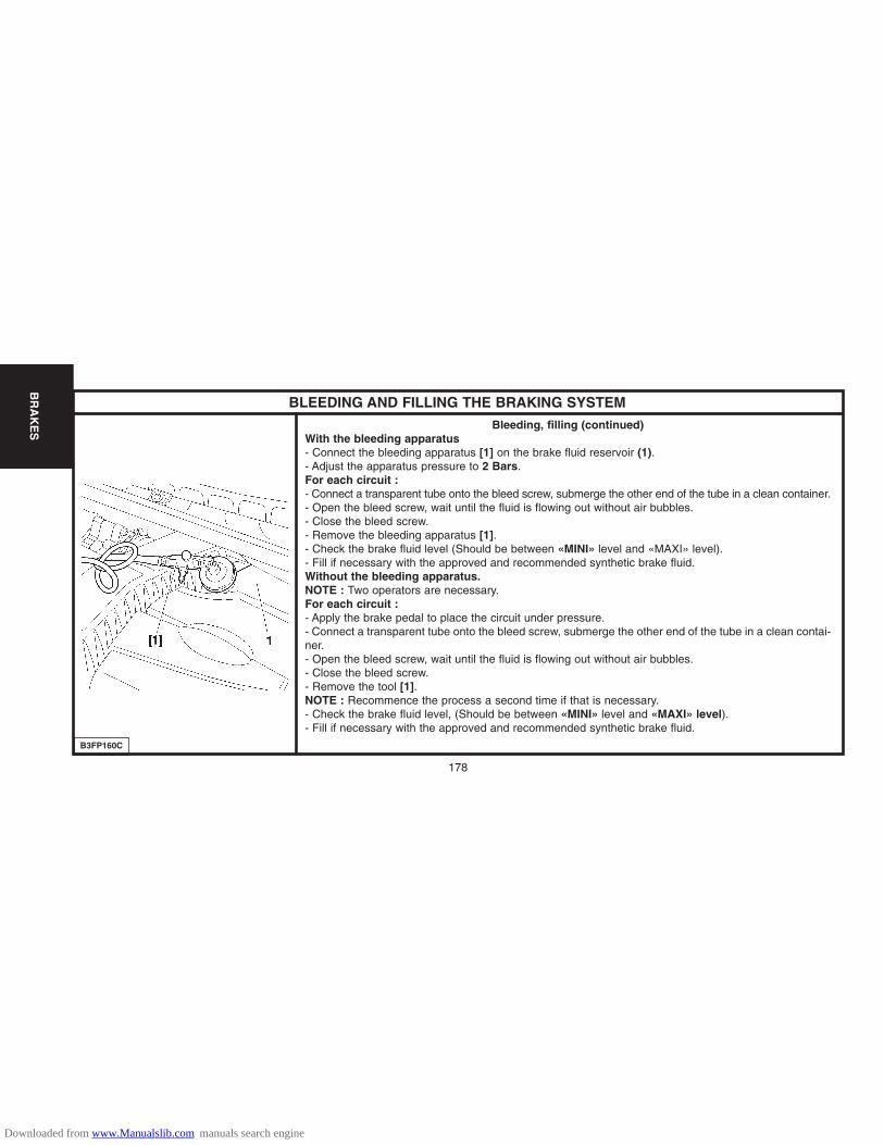
178
BR
AK
ES
B3FP160C
BLEEDING AND FILLING THE BRAKING SYSTEM
Bleeding, filling (continued)With the bleeding apparatus- Connect the bleeding apparatus [1] on the brake fluid reservoir (1).- Adjust the apparatus pressure to 2 Bars.For each circuit : - Connect a transparent tube onto the bleed screw, submerge the other end of the tube in a clean container.- Open the bleed screw, wait until the fluid is flowing out without air bubbles.- Close the bleed screw.- Remove the bleeding apparatus [1].- Check the brake fluid level (Should be between «MINI» level and «MAXI» level).- Fill if necessary with the approved and recommended synthetic brake fluid.Without the bleeding apparatus.NOTE : Two operators are necessary.For each circuit :- Apply the brake pedal to place the circuit under pressure.- Connect a transparent tube onto the bleed screw, submerge the other end of the tube in a clean contai-ner.- Open the bleed screw, wait until the fluid is flowing out without air bubbles.- Close the bleed screw.- Remove the tool [1].NOTE : Recommence the process a second time if that is necessary.- Check the brake fluid level, (Should be between «MINI» level and «MAXI» level).- Fill if necessary with the approved and recommended synthetic brake fluid.
Downloaded from www.Manualslib.com manuals search engine

179
EL
EC
TR
ICA
LS
YS
TE
M
ESSENTIAL : Respect the safety and cleanliness requirements.
The pre-heating time varies according to the engine coolant temperature.
The pre-post heating control unit is managed by the engine ECU.
Pre-post heating control unit
Supplier CARTIER NAGARESReference 96 399 073 80 96 399 074 80
Pre-heater plug«A» Marking zone
Supplier NGKReference YE04
Tightening torques
Plugs on cylinder head : 0,85 ± 0,08 m daNBar on plugs : 0,12 ± 0,03 m.daN
FEATURES OF THE PRE-POSTHEATING CIRCUIT
D1AP01SC
Downloaded from www.Manualslib.com manuals search engine

180
EL
EC
TR
ICA
LS
YS
TE
M
STARTER MOTORSAbbreviations and definitions
Coding of climatees is as follows :
CLIMATEES :
C Hot : Starting possible as low as -18°CT Temperate : Starting possible as low as -18°CF Cold : Starting possible as low as -25°CGF Very cold : Starting possible as low as -30°C
Meaning of abbreviations :
BVM : Manual gearbox
BVMP : Piloted manual gearbox
REFRI : Air conditioning
Downloaded from www.Manualslib.com manuals search engine
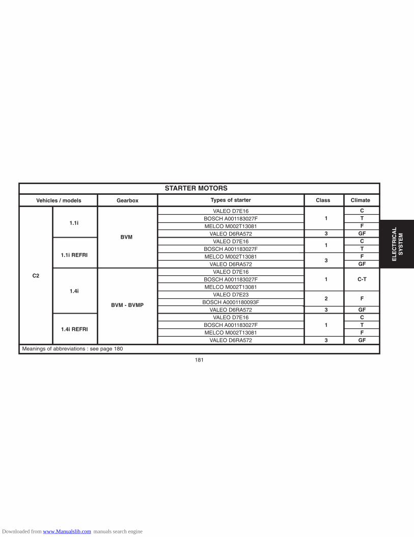
EL
EC
TR
ICA
LS
YS
TE
M
181
VALEO D7E16BOSCH A001183027FMELCO M002T13081
VALEO D6RA572VALEO D7E16
BOSCH A001183027FMELCO M002T13081
VALEO D6RA572VALEO D7E16
BOSCH A001183027FMELCO M002T13081
VALEO D7E23BOSCH A0001180093F
VALEO D6RA572VALEO D7E16
BOSCH A001183027FMELCO M002T13081
VALEO D6RA572
C1 T
F3 GF
1CT
3F
GF
1 C-T
2 F
3 GFC
1 TF
3 GF
STARTER MOTORS
Class ClimateGearboxVehicles / models Types of starter
Meanings of abbreviations : see page 180
1.1i
BVM
1.1i REFRI
1.4i
1.4i REFRI
C2
BVM - BVMP
Downloaded from www.Manualslib.com manuals search engine

182
EL
EC
TR
ICA
LS
YS
TE
M
VALEO D6RA572
VALEO D6RA110
VALEO D7GP09
DENSO 5S228000-001
CTF
GFCTF
GF
STARTER MOTORS
Class ClimateTypes of starter
1.6i 16V
BVM
BVMP
14.HD i
C2
3
4
5
Meanings of abbreviations : see page 180
GearboxVehicles / models
Downloaded from www.Manualslib.com manuals search engine

183
EL
EC
TR
ICA
LS
YS
TE
M
ALTERNATORSAbbreviations and definitions
Coding of climates is as follows :
CLIMATES :
C Hot : Starting possible as low as -18°CT Temperate : Starting possible as low as -18°CF Cold : Starting possible as low as -25°CGF Very cold : Starting possible as low as -30°C
Meaning of abbreviations :
BVM : Manual gearbox
BVMP : Piloted manual gearbox
NON REFRI : Without air conditioning
REFRI : With air conditioning
Downloaded from www.Manualslib.com manuals search engine
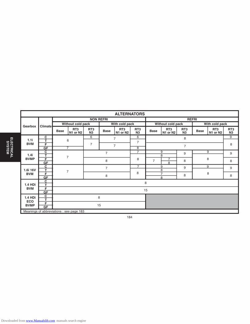
CTF
GFCTF
GFCTF
GFCTF
GFCTF
GF
ALTERNATORSREFRINON REFRI
Without cold pack With cold pack Without cold pack With cold packGearbox Climate
RT3N1 or N2
RT3N3 Base RT3
N1 or N2RT3N3Base RT3
N1 or N2RT3N3 Base RT3
N1 or N2RT3N3Base
184
EL
EC
TR
ICA
LS
YS
TE
M
1.1iBVM
1.4iBVMP
1.6i 16VBVM
1.4 HDiBVM
1.4 HDiECO
BVMP
Meanings of abbreviations : see page 183
6
7
7
7
7
6 6 8
7
9
8
9
8 8
8
9
7
87 9 9 9
878
878
9 9
8
7
7
7
8 78
8
7 7
8
8
15
8
15
8
9
8
Downloaded from www.Manualslib.com manuals search engine

EL
EC
TR
ICA
LS
YS
TE
M
Checking the alternator outputConnect as shown in the diagram opposite, using an ammeter (A), a voltmeter (V), and a rheostat (R) ora Volt/Ammeter/Rheostat combination.Referring to the vehicle’s equipment specification (see table opposite), adjust the engine speed andrheostat charge to obtain U=13.5V.Reminder : The excitation energising current will flow through the warning lamp; check that the warninglamp comes on when the ignition is switched on. It should go out when the engine has started (accelerateslightly).
Checking the voltage regulatorSet the rheostat to zero and disconnect all the electrical consumers.Display 3000 alternator rpm. If U alternator is > 14.7 V, the regulator is faulty.Note: These tests should be performed with the engine hot and the battery fully charged.
Method of reading the alternator speedFit a reflecting shim on the pulley of the alternator.Adjust a stroboscope to the frequency equivalent to the control speed. (e.g. 2000 rpm = 2000/60 = 83 Hz)Adjust the engine speed so that the shim appears fixed.
CHARGING CIRCUIT - ALTERNATOR WITH MONO-FUNCTION REGULATOR
D1AP025C
185
A : AmmeterB : BatteryG : GeneratorL : Warning lampK1 and K2 : SwitchR : Electric chargeS : Shunt 200mV/200AV : Voltmeter1 : Alternator.
Downloaded from www.Manualslib.com manuals search engine
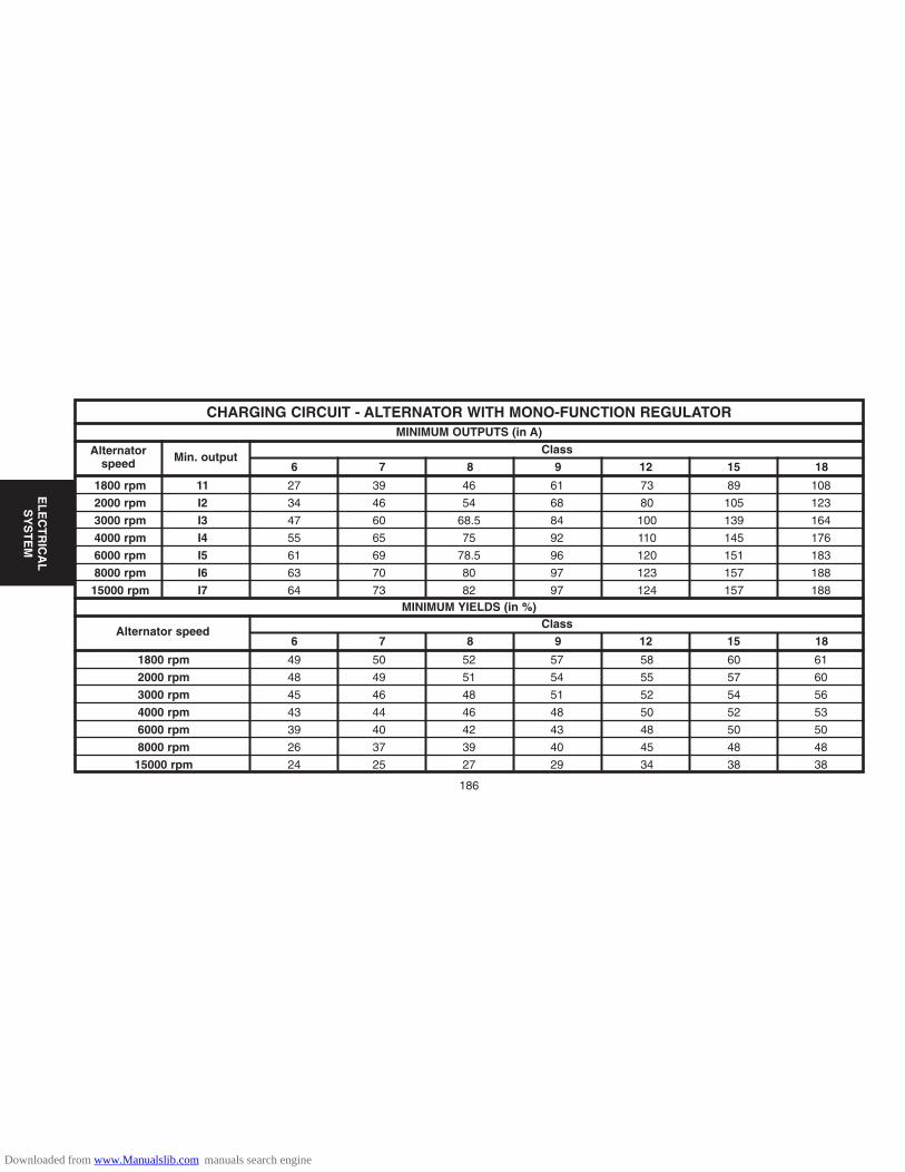
CHARGING CIRCUIT - ALTERNATOR WITH MONO-FUNCTION REGULATORMINIMUM OUTPUTS (in A)
MINIMUM YIELDS (in %)
Alternatorspeed Min. output
Class
6 7 8 9 12 15 18
186
EL
EC
TR
ICA
LS
YS
TE
M
Alternator speedClass
6 7 8 9 12 15 18
1800 rpm 11 27 39 46 61 73 89 108
2000 rpm I2 34 46 54 68 80 105 123
3000 rpm I3 47 60 68.5 84 100 139 164
4000 rpm I4 55 65 75 92 110 145 176
6000 rpm I5 61 69 78.5 96 120 151 183
8000 rpm I6 63 70 80 97 123 157 188
15000 rpm I7 64 73 82 97 124 157 188
1800 rpm 49 50 52 57 58 60 61
2000 rpm 48 49 51 54 55 57 60
3000 rpm 45 46 48 51 52 54 56
4000 rpm 43 44 46 48 50 52 53
6000 rpm 39 40 42 43 48 50 50
8000 rpm 26 37 39 40 45 48 48
15000 rpm 24 25 27 29 34 38 38
Downloaded from www.Manualslib.com manuals search engine

NAGARES 960411-PCARTIER 735068
NGK YE04
PRE-HEATING AND STARTING SYSTEMS
Vehicles - models Pre-heater plugs Pre-heater control unitPre / Post heating
(pre-heating duration at 20°C)
C2 1.4 HDI 8HX Controlled by the diesel injectionECU
187
EL
EC
TR
ICA
LS
YS
TE
M
Downloaded from www.Manualslib.com manuals search engine
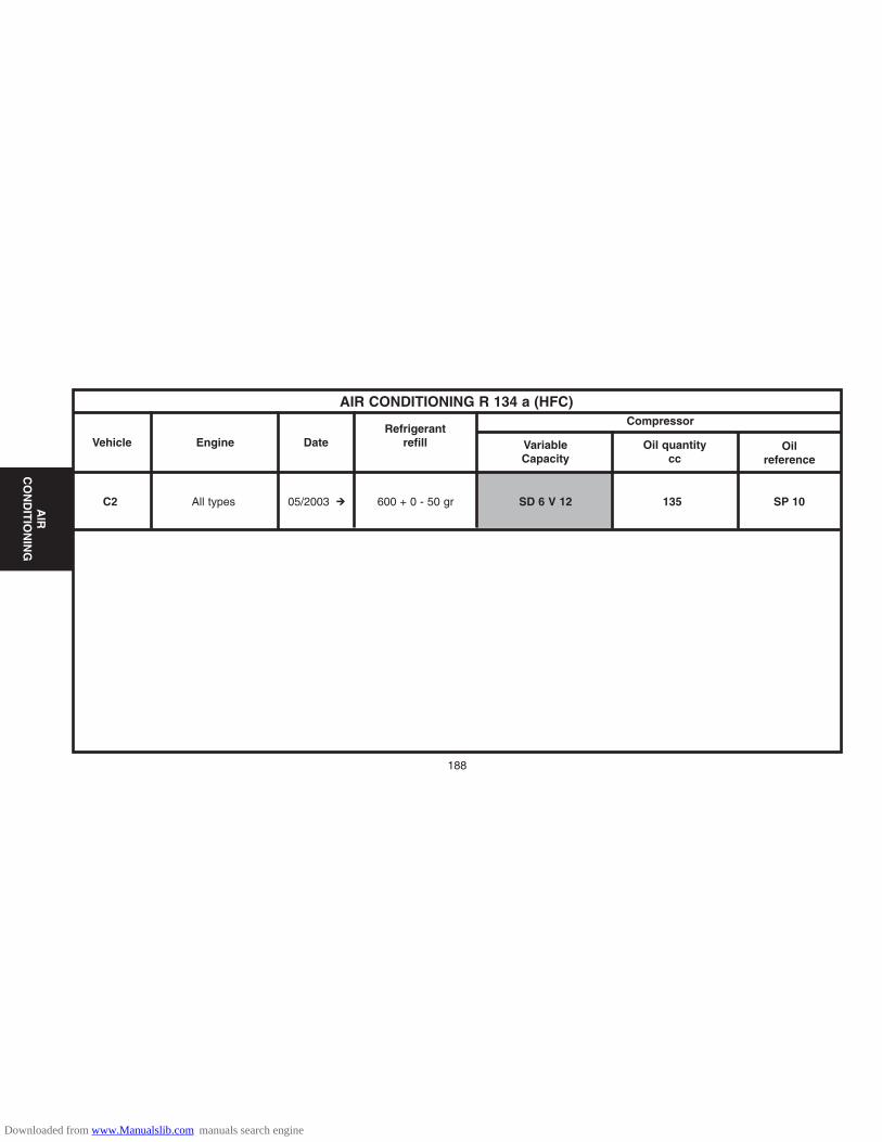
188
C2 All types 05/2003 # 600 + 0 - 50 gr SD 6 V 12 135 SP 10
AIR CONDITIONING R 134 a (HFC)
Vehicle Engine DateRefrigerant
refill
Compressor
VariableCapacity
Oil quantitycc
Oilreference
AIR
CO
ND
ITIO
NIN
G
Downloaded from www.Manualslib.com manuals search engine
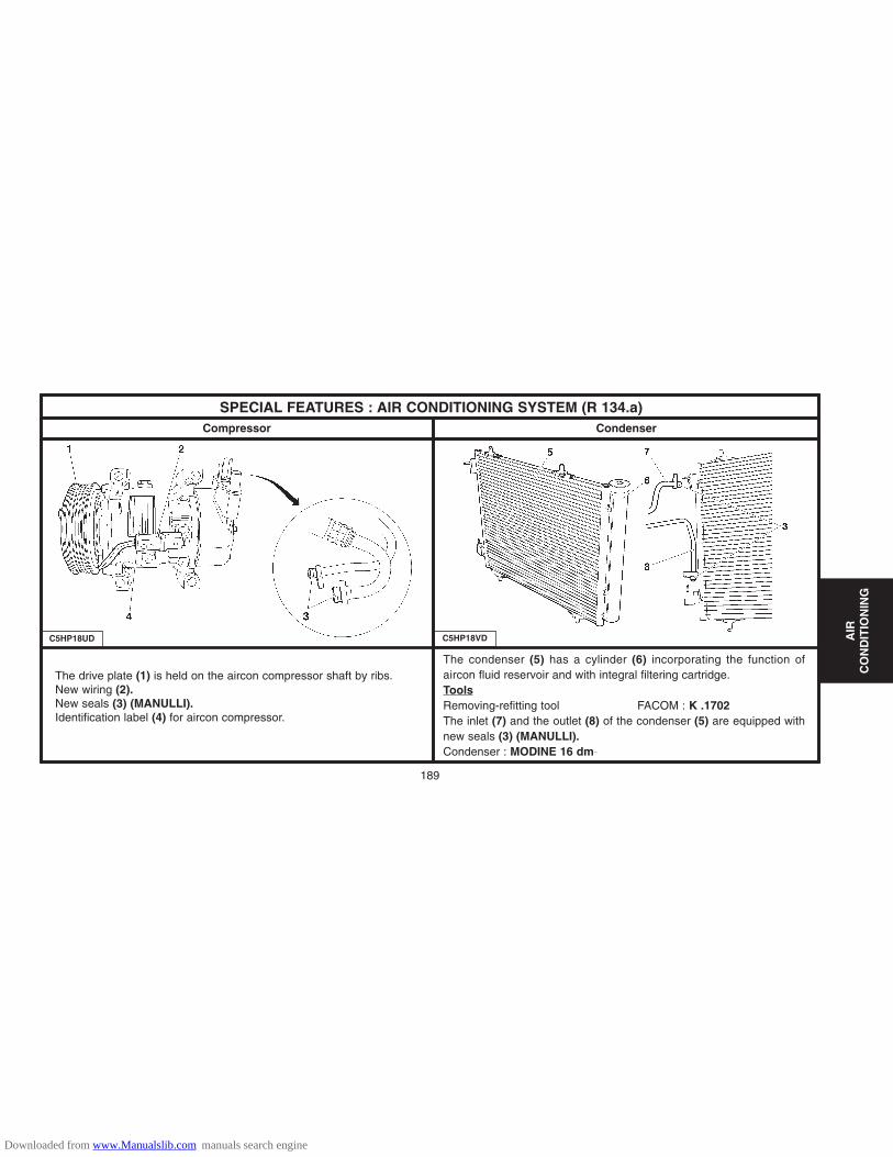
The condenser (5) has a cylinder (6) incorporating the function ofaircon fluid reservoir and with integral filtering cartridge.ToolsRemoving-refitting tool FACOM : K .1702The inlet (7) and the outlet (8) of the condenser (5) are equipped withnew seals (3) (MANULLI).Condenser : MODINE 16 dm_
The drive plate (1) is held on the aircon compressor shaft by ribs.New wiring (2).New seals (3) (MANULLI).Identification label (4) for aircon compressor.
SPECIAL FEATURES : AIR CONDITIONING SYSTEM (R 134.a)CondenserCompressor
C5HP18UD C5HP18VD
189
AIR
CO
ND
ITIO
NIN
G
Downloaded from www.Manualslib.com manuals search engine
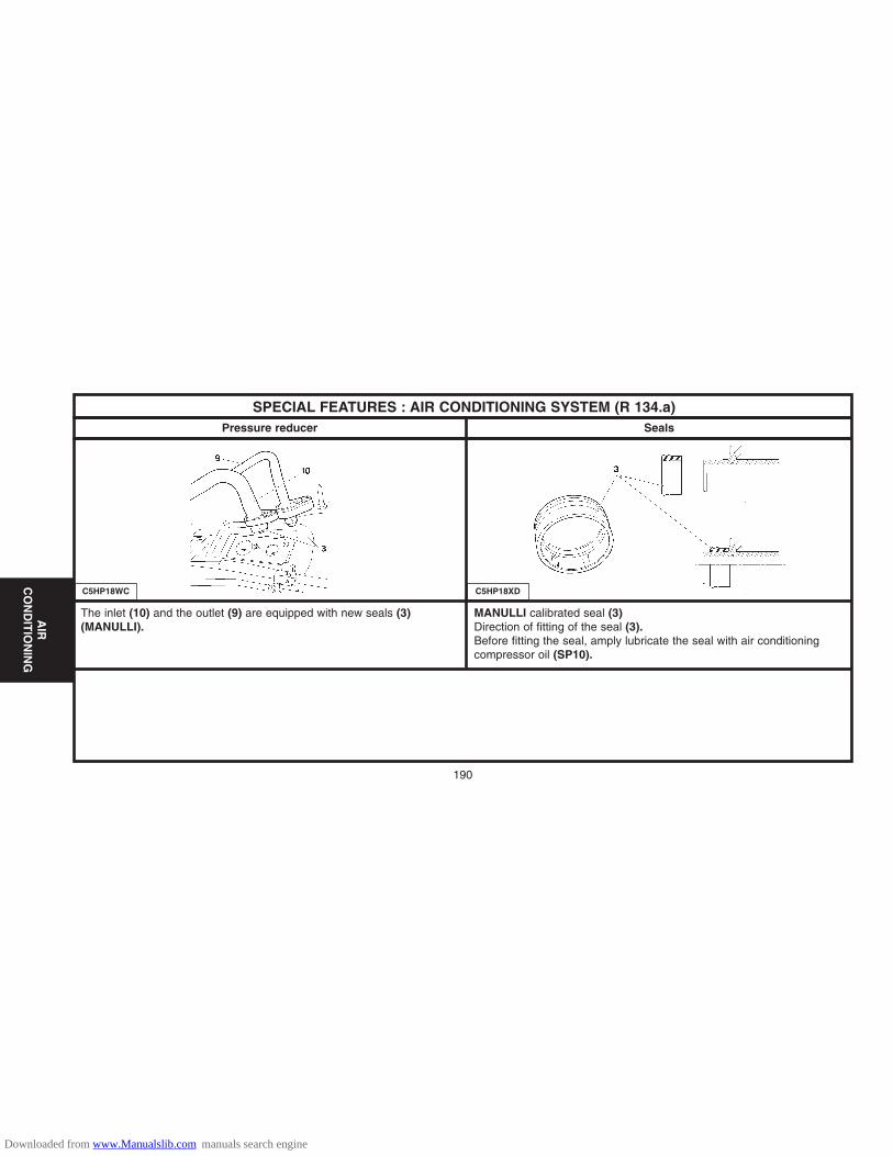
190
SPECIAL FEATURES : AIR CONDITIONING SYSTEM (R 134.a)SealsPressure reducer
C5HP18WC C5HP18XD
The inlet (10) and the outlet (9) are equipped with new seals (3)(MANULLI).
MANULLI calibrated seal (3)Direction of fitting of the seal (3).Before fitting the seal, amply lubricate the seal with air conditioningcompressor oil (SP10).
AIR
CO
ND
ITIO
NIN
G
Downloaded from www.Manualslib.com manuals search engine

SPECIAL FEATURES : AIR CONDITIONING SYSTEM (R 134.a)Pollen filter
Note: The pollen filter is located in the engine compartment on the RH side.
Removing
Pull on the tab of the plastic cover (1), at «a».
Tilt the flap (2).
Remove the pollen filter (3)
Refitting
Proceed in reverse order.
C4AP1BRC C4AP1BSC C4AP1BTC
191
AIR
CO
ND
ITIO
NIN
G
Downloaded from www.Manualslib.com manuals search engine

192
SPECIAL FEATURES : AIR CONDITIONING SYSTEM (R 134.a)Changing the filtering/drying cartridge
Tools.[1] Charge station : (according to workshop equipment)[2] TORX adaptor : TORX 70 FACOM.[3] Inertia extractor :1671-T. Toolkit 4114-T[4] Endpiece Ø 20 : 1671-T.D20.[5] Set of plugs : (-).0188.T.[6] Circlip pliers : FACOM.
RemovingDepressurise the aircon circuit, using tool [1].Remove the front bumper (see corresponding operation).Remove the pin (1).Unclip the condenser at «a» and «b», using a screwdriver.Tilt the condenser towards the front.Lift and release the condenser.Clean the area around the cap (2).Remove the plastic cap (2), using tool [2].Remove the safety circlip (3), using tool [6].Position the tool [3] and [4] in the aperture of the cartridge (5).Extract the cartridge (5) from the reservoir (4), using tool [3] and [4].Block the reservoir (4), using tool [5].
C4AP1BUC C4AP1BVC C4AP1BXCC4AP1BWC
AIR
CO
ND
ITIO
NIN
G
Downloaded from www.Manualslib.com manuals search engine

193
SPECIAL FEATURES : AIR CONDITIONING SYSTEM (R 134.a)Changing the filtering/drying cartridge
RefittingRemove the new cartridge from its packaging.Do not expose the cartridge, the filter and seals to pollutants.Lightly oil the seals (compressor oil).Remove tool [5] from the reservoir (4).Insert the new cartridge (5) into the reservoir (4).Refit the safety circlip (3), using tool [6].Make sure that the circlip (3) is correctly positioned in its location.
WARNING : Not more than 5 minutes should elapse between the removalof the cartridge (5) from its packaging and its being fitted.
Refit: - The plastic cap (2), using tool [5]- Tighten to 1,2 ± 0,1 m.daN.- The condenser (reclip, pushing at «a» and «b»).- The pin (1).- The front bumper (see corresponding operation).Proceed to: - Recharge the circuit (see corresponding operation).- Check the operation of the air conditioning (see corresponding operation).
C4AP1BYC C4AP1BWC C4AP1BVCC4AP1BUC
AIR
CO
ND
ITIO
NIN
G
Downloaded from www.Manualslib.com manuals search engine

194
SPECIAL FEATURES : AIR CONDITIONING SYSTEM (R 134.a)Compressor lubricant
ESSENTIAL: The compressor lubricant is extremely hygroscopic; always use FRESH oil.
Checking the compressor oil level.
There are three specific cases :- 1/ Repairs to a system without leaks.- 2/ Slow leak.- 3/ Fast leak.
1/ Repairing a system without leaks.a) - Using draining/recovery equipment not fitted with an oil decanter.- Drain the system as slowly as possible via the LOW PRESSURE valve, so as not to lose any oil.- No more oil should be added when filling the system with R 134.a fluid.b) - Using draining/filling equipment fitted with an oil decanter.- Drain the R 134.a fluid from the system in accordance with the instructions in the equipment handbook.- Measure the amount of oil recovered.- Add the same amount of NEW oil when filling the system with R 134.a fluid.c) - Replacing a compressor.- Remove the old compressor, drain it and measure the oil quantity.- Drain the new compressor (supplied full), so that the same amount of NEW oil is left in the compressor as was in the old compressor.
AIR
CO
ND
ITIO
NIN
G
Downloaded from www.Manualslib.com manuals search engine

SPECIAL FEATURES : AIR CONDITIONING SYSTEM (R 134.a)
Checking the compressor oil level (continued)
2/ Slow leak.
- Slow leaks do not lead to oil loss, therefore the same procedure should be followed as if there was no leak at all.
3/ Fast leak.
This type of leak causes both oil loss as well as allowing air to enter the system.
It is therefore necessary to :
- Replace the dryer.- Drain as much oil as possible (when replacing the faulty component).
Either before or during filling of the system with R 134.a fluid, introduce 80 cc of NEW oil into the system.
195
AIR
CO
ND
ITIO
NIN
G
Downloaded from www.Manualslib.com manuals search engine

196
AIR CONDITIONING CIRCUIT R 134.a
(1) High pressure valve.
(2) Low pressure valve
(3) Pressostat
(4) Filter.
Tightening torque m.daN
(a) : 0.6(b) : 0.6(c) : 0.6(d) : 0.6(e) : 0.6(f) : 0.7
C5HP19UP
AIR
CO
ND
ITIO
NIN
G
Downloaded from www.Manualslib.com manuals search engine