manually-operated m-force switch installation and ... · 1 manually-operated m-force switch...
TRANSCRIPT
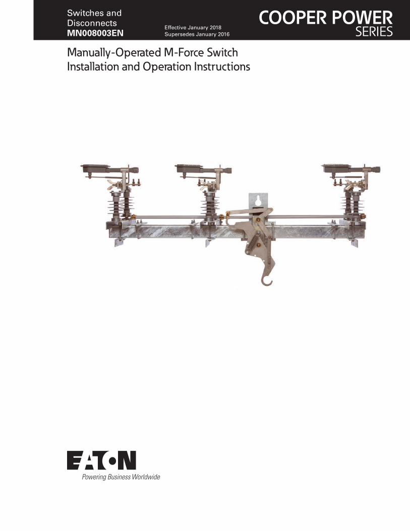
Manually-Operated M-Force Switch Installation and Operation Instructions
COOPER POWERSERIES
Switches and Disconnects MN008003EN
Effective January 2018Supersedes January 2016

ii InstallatIon and operatIon InstructIons MN008003EN January 2018
DISCLAIMER OF WARRANTIES AND LIMITATION OF LIABILITYThe information, recommendations, descriptions and safety notations in this document are based on Eaton Corporation’s (“Eaton”) experience and judgment and may not cover all contingencies. If further information is required, an Eaton sales office should be consulted. Sale of the product shown in this literature is subject to the terms and conditions outlined in appropriate Eaton selling policies or other contractual agreement between Eaton and the purchaser.
THERE ARE NO UNDERSTANDINGS, AGREEMENTS, WARRANTIES, EXPRESSED OR IMPLIED, INCLUDING WARRANTIES OF FITNESS FOR A PARTICULAR PURPOSE OR MERCHANTABILITY, OTHER THAN THOSE SPECIFICALLY SET OUT IN ANY EXISTING CONTRACT BETWEEN THE PARTIES. ANY SUCH CONTRACT STATES THE ENTIRE OBLIGATION OF EATON. THE CONTENTS OF THIS DOCUMENT SHALL NOT BECOME PART OF OR MODIFY ANY CONTRACT BETWEEN THE PARTIES.
In no event will Eaton be responsible to the purchaser or user in contract, in tort (including negligence), strict liability or otherwise for any special, indirect, incidental or consequential damage or loss whatsoever, including but not limited to damage or loss of use of equipment, plant or power system, cost of capital, loss of power, additional expenses in the use of existing power facilities, or claims against the purchaser or user by its customers resulting from the use of the information, recommendations, and descriptions contained herein. The information contained in this manual is subject to change without notice.
iiiInstallatIon and operatIon InstructIons MN008003EN January 2018
Contents
DISCLAIMER OF WARRANTIES AND LIMITATION OF LIABILITY . . . . . . . . . . . . . . . . . . . . . . . . . . . . . . . . . . . ii
SAFETY FOR LIFE . . . . . . . . . . . . . . . . . . . . . . . . . . . . . . . . . . . . . . . . . . . . . . . . . . . . . . . . . . . . . . . . . . . . . . . . . v
SAFETY INFORMATION . . . . . . . . . . . . . . . . . . . . . . . . . . . . . . . . . . . . . . . . . . . . . . . . . . . . . . . . . . . . . . . . . . . . vSafety instructions . . . . . . . . . . . . . . . . . . . . . . . . . . . . . . . . . . . . . . . . . . . . . . . . . . . . . . . . . . . . . . . . . . . . . . . . . . . . . . .v
INTRODUCTION . . . . . . . . . . . . . . . . . . . . . . . . . . . . . . . . . . . . . . . . . . . . . . . . . . . . . . . . . . . . . . . . . . . . . . . . . . . 1Read this manual first . . . . . . . . . . . . . . . . . . . . . . . . . . . . . . . . . . . . . . . . . . . . . . . . . . . . . . . . . . . . . . . . . . . . . . . . . . . .1
Additional information . . . . . . . . . . . . . . . . . . . . . . . . . . . . . . . . . . . . . . . . . . . . . . . . . . . . . . . . . . . . . . . . . . . . . . . . . . . .1
Acceptance and initial inspection . . . . . . . . . . . . . . . . . . . . . . . . . . . . . . . . . . . . . . . . . . . . . . . . . . . . . . . . . . . . . . . . . . .1
Handling and storage . . . . . . . . . . . . . . . . . . . . . . . . . . . . . . . . . . . . . . . . . . . . . . . . . . . . . . . . . . . . . . . . . . . . . . . . . . . . .1
Quality standards. . . . . . . . . . . . . . . . . . . . . . . . . . . . . . . . . . . . . . . . . . . . . . . . . . . . . . . . . . . . . . . . . . . . . . . . . . . . . . . .1
DESCRIPTION OF OPERATION . . . . . . . . . . . . . . . . . . . . . . . . . . . . . . . . . . . . . . . . . . . . . . . . . . . . . . . . . . . . . . 1
RATINGS AND SPECIFICATIONS . . . . . . . . . . . . . . . . . . . . . . . . . . . . . . . . . . . . . . . . . . . . . . . . . . . . . . . . . . . . . 2Check switch ratings prior to installation . . . . . . . . . . . . . . . . . . . . . . . . . . . . . . . . . . . . . . . . . . . . . . . . . . . . . . . . . . . . .2
DIMENSIONS AND WEIGHTS . . . . . . . . . . . . . . . . . . . . . . . . . . . . . . . . . . . . . . . . . . . . . . . . . . . . . . . . . . . . . . . . 2Shipping weights and dimensions . . . . . . . . . . . . . . . . . . . . . . . . . . . . . . . . . . . . . . . . . . . . . . . . . . . . . . . . . . . . . . . . . . .2
Standard M-Force switch configurations . . . . . . . . . . . . . . . . . . . . . . . . . . . . . . . . . . . . . . . . . . . . . . . . . . . . . . . . . . . . . .3
Phase units . . . . . . . . . . . . . . . . . . . . . . . . . . . . . . . . . . . . . . . . . . . . . . . . . . . . . . . . . . . . . . . . . . . . . . . . . . . . . . . . . . . .5
Insulators . . . . . . . . . . . . . . . . . . . . . . . . . . . . . . . . . . . . . . . . . . . . . . . . . . . . . . . . . . . . . . . . . . . . . . . . . . . . . . . . . . . . . .6
INSTALLATION PROCEDURE . . . . . . . . . . . . . . . . . . . . . . . . . . . . . . . . . . . . . . . . . . . . . . . . . . . . . . . . . . . . . . . . 7Mounting instructions . . . . . . . . . . . . . . . . . . . . . . . . . . . . . . . . . . . . . . . . . . . . . . . . . . . . . . . . . . . . . . . . . . . . . . . . . . . .7
GROUNDING . . . . . . . . . . . . . . . . . . . . . . . . . . . . . . . . . . . . . . . . . . . . . . . . . . . . . . . . . . . . . . . . . . . . . . . . . . . . . 8Grounding the M-Force switch . . . . . . . . . . . . . . . . . . . . . . . . . . . . . . . . . . . . . . . . . . . . . . . . . . . . . . . . . . . . . . . . . . . . .8
SWITCH OPERATION . . . . . . . . . . . . . . . . . . . . . . . . . . . . . . . . . . . . . . . . . . . . . . . . . . . . . . . . . . . . . . . . . . . . . . . 9Manual switch operation . . . . . . . . . . . . . . . . . . . . . . . . . . . . . . . . . . . . . . . . . . . . . . . . . . . . . . . . . . . . . . . . . . . . . . . . . .9
Returning the switch to service . . . . . . . . . . . . . . . . . . . . . . . . . . . . . . . . . . . . . . . . . . . . . . . . . . . . . . . . . . . . . . . . . . .10
MAINTENANCE . . . . . . . . . . . . . . . . . . . . . . . . . . . . . . . . . . . . . . . . . . . . . . . . . . . . . . . . . . . . . . . . . . . . . . . . . . .10Control rods and mechanisms . . . . . . . . . . . . . . . . . . . . . . . . . . . . . . . . . . . . . . . . . . . . . . . . . . . . . . . . . . . . . . . . . . . . .10
Mounting hardware . . . . . . . . . . . . . . . . . . . . . . . . . . . . . . . . . . . . . . . . . . . . . . . . . . . . . . . . . . . . . . . . . . . . . . . . . . . . .10
Terminal pads . . . . . . . . . . . . . . . . . . . . . . . . . . . . . . . . . . . . . . . . . . . . . . . . . . . . . . . . . . . . . . . . . . . . . . . . . . . . . . . . .10
Switch motion . . . . . . . . . . . . . . . . . . . . . . . . . . . . . . . . . . . . . . . . . . . . . . . . . . . . . . . . . . . . . . . . . . . . . . . . . . . . . . . . .10
Reliabreak interrupter . . . . . . . . . . . . . . . . . . . . . . . . . . . . . . . . . . . . . . . . . . . . . . . . . . . . . . . . . . . . . . . . . . . . . . . . . . .10
Blades and clip contacts . . . . . . . . . . . . . . . . . . . . . . . . . . . . . . . . . . . . . . . . . . . . . . . . . . . . . . . . . . . . . . . . . . . . . . . . .10
TROUBLESHOOTING PROCEDURES . . . . . . . . . . . . . . . . . . . . . . . . . . . . . . . . . . . . . . . . . . . . . . . . . . . . . . . . . .11Phase spacing . . . . . . . . . . . . . . . . . . . . . . . . . . . . . . . . . . . . . . . . . . . . . . . . . . . . . . . . . . . . . . . . . . . . . . . . . . . . . . . . . 11
Closed position of blade . . . . . . . . . . . . . . . . . . . . . . . . . . . . . . . . . . . . . . . . . . . . . . . . . . . . . . . . . . . . . . . . . . . . . . . . . 11
Contact resistance. . . . . . . . . . . . . . . . . . . . . . . . . . . . . . . . . . . . . . . . . . . . . . . . . . . . . . . . . . . . . . . . . . . . . . . . . . . . . . 11
Reliabreak positioning . . . . . . . . . . . . . . . . . . . . . . . . . . . . . . . . . . . . . . . . . . . . . . . . . . . . . . . . . . . . . . . . . . . . . . . . . . . 11
Reliabreak arm . . . . . . . . . . . . . . . . . . . . . . . . . . . . . . . . . . . . . . . . . . . . . . . . . . . . . . . . . . . . . . . . . . . . . . . . . . . . . . . . . 11
iv InstallatIon and operatIon InstructIons MN008003EN January 2018
RELIABREAK REPLACEMENT INSTRUCTIONS . . . . . . . . . . . . . . . . . . . . . . . . . . . . . . . . . . . . . . . . . . . . . . . . . 13Replacing a Reliabreak unit with the offset mounting configuration (October 2016 - present) . . . . . . . . . . . . . . . . . . .13
Replacing a Reliabreak unit with a U-bolt and mounting pipe configuration (pre-2015 version) . . . . . . . . . . . . . . . . . . .14
Converting a shared bolt mounting to current offset mounting configuration (April 2015 - October 2016) . . . . . . . . . .15
Converting the old U-bolt configuration to the new offset mounting configuration . . . . . . . . . . . . . . . . . . . . . . . . . . . .15
GUIDE TO PROPER OPERATION OF A RELIABREAK TYPE INTERRUPTER . . . . . . . . . . . . . . . . . . . . . . . . . . . 16Pre-stroke . . . . . . . . . . . . . . . . . . . . . . . . . . . . . . . . . . . . . . . . . . . . . . . . . . . . . . . . . . . . . . . . . . . . . . . . . . . . . . . . . . . .16
Mid-stroke (loadbreak) . . . . . . . . . . . . . . . . . . . . . . . . . . . . . . . . . . . . . . . . . . . . . . . . . . . . . . . . . . . . . . . . . . . . . . . . . . .16
Release of arm . . . . . . . . . . . . . . . . . . . . . . . . . . . . . . . . . . . . . . . . . . . . . . . . . . . . . . . . . . . . . . . . . . . . . . . . . . . . . . . .16
ADJUSTMENTS . . . . . . . . . . . . . . . . . . . . . . . . . . . . . . . . . . . . . . . . . . . . . . . . . . . . . . . . . . . . . . . . . . . . . . . . . . 161/8" clearance gap . . . . . . . . . . . . . . . . . . . . . . . . . . . . . . . . . . . . . . . . . . . . . . . . . . . . . . . . . . . . . . . . . . . . . . . . . . . . . .16
Reliabreak arm . . . . . . . . . . . . . . . . . . . . . . . . . . . . . . . . . . . . . . . . . . . . . . . . . . . . . . . . . . . . . . . . . . . . . . . . . . . . . . . . .17
Trip rod . . . . . . . . . . . . . . . . . . . . . . . . . . . . . . . . . . . . . . . . . . . . . . . . . . . . . . . . . . . . . . . . . . . . . . . . . . . . . . . . . . . . . . .17
Trip arm return . . . . . . . . . . . . . . . . . . . . . . . . . . . . . . . . . . . . . . . . . . . . . . . . . . . . . . . . . . . . . . . . . . . . . . . . . . . . . . . . .17
v
Manually-Operated M-Force Switch
InstallatIon and operatIon InstructIons MN008003EN January 2018
Safety for life
Eaton meets or exceeds all applicable industry standards relating to product safety in its Cooper Power™ series products. We actively promote safe practices in the use and maintenance of our products through our service literature, instructional training programs, and the continuous efforts of all Eaton employees involved in product design, manufacture, marketing, and service.
We strongly urge that you always follow all locally-approved safety procedures and safety instructions when working around high-voltage lines and equipment, and support our “Safety For Life” mission.
Safety information
The instructions in this manual are not intended as a substitute for proper training or adequate experience in the safe operation of the equipment described. Only competent technicians who are familiar with this equipment should install, operate, and service it.
A competent technician has these qualifications:
Is thoroughly familiar with these instructions.
Is trained in industry-accepted high- and low-voltage safe operating practices and procedures.
Is trained and authorized to energize, de-energize, clear, and ground power distribution equipment.
Is trained in the care and use of protective equipment such as arc flash clothing, safety glasses, face shield, hard hat, rubber gloves, clampstick, hotstick, etc.
Following is important safety information. For safe installation and operation of this equipment, be sure to read and understand all cautions and warnings.
Hazard Statement DefinitionsThis manual may contain four types of hazard statements:
DANGERIndicates an imminently hazardous situation which, if not avoided, will result in death or serious injury .
WARNINGIndicates a potentially hazardous situation which, if not avoided, could result in death or serious injury .
CAUTIONIndicates a potentially hazardous situation which, if not avoided, may result in minor or moderate injury .
NOTICEIndicates a potentially hazardous situation which, if not avoided, may result in equipment damage only .
Safety instructionsFollowing are general caution and warning statements that apply to this equipment. Additional statements, related to specific tasks and procedures, are located throughout the manual.
DANGERHazardous voltage . Contact with hazardous voltage will cause death or severe personal injury . Follow all locally-approved safety procedures when working around high- and low-voltage lines and equipment . G103 .3
WARNINGBefore installing, operating, maintaining, or testing this equipment, carefully read and understand the contents of this manual . Improper operation, handling, or maintenance can result in death, severe personal injury, and equipment damage . G101 .0
WARNINGThis equipment is not intended to protect human life . Follow all locally-approved procedures and safety practices when installing or operating this equipment . Failure to comply can result in death, severe personal injury, and equipment damage . G102 .1
WARNINGPower distribution and transmission equipment must be properly selected for the intended application . It must be installed and serviced by competent personnel who have been trained and understand proper safety procedures . These instructions are written for such personnel and are not a substitute for adequate training and experience in safety procedures . Failure to properly select, install, or maintain power distribution and transmission equipment can result in death, severe personal injury, and equipment damage . G122 .2
!SAFETYFOR LIFE
!SAFETYFOR LIFE

vi
Manually-Operated M-Force Switch
InstallatIon and operatIon InstructIons MN008003EN January 2018
his page is intentionally left blank.T
1
Manually-Operated M-Force Switch
InstallatIon and operatIon InstructIons MN008003EN January 2018
IntroductionThis manual provides installation and operation instructions for Eaton’s Cooper Power™ series M-Force™ three-phase overhead loadbreak switch.
Read this manual firstRead and understand the contents of this manual and follow all locally approved procedures and safety practices before installing or operating this equipment.
Additional informationThese instructions cannot cover all details or variations in the equipment, procedures, or processes described, nor provide directions for meeting every possible contingency during installation, operation, or maintenance. When additional information is desired to satisfy a problem not covered sufficiently for the user’s purpose, contact your Eaton sales representative.
Acceptance and initial inspectionEach switch is completely assembled, inspected, tested, and adjusted at the factory. It is in good condition when accepted by the carrier for shipment. Upon receipt of a switch, inspect the switch thoroughly for damage and loss of parts incurred during shipment. If damage or loss is discovered, file a claim with the carrier immediately.
Handling and storageBe careful during handling and storage of the switch to minimize the possibility of damage.
If the switch is to be stored for an appreciable time before installation, provide a clean, dry storage area. Locate the switch so as to minimize the possibility of mechanical damage.
Quality standardsISO 9001:Certified Quality Management System.
Description of operation The M-Force switch is a distribution-class, gang operated, and factory unitized three-phase overhead loadbreak switch, offered in distribution voltage classifications of 15.5 kV, 27 kV, and 38 kV. The M-Force switch may be used for line sectionalizing, paralleling, by-passing, and isolating. M-Force stands for “magnetic force.” The switch has reverse loop contacts found on distribution-class sidebreak switches; a contact usually reserved for transmission switches. The reverse loop contacts utilize high current magnetic forces for added reliability. The reverse loop design allows for high contact pressure to be maintained during fault conditions. This feature prevents pitting and distorting of the switch blade and contacts even under momentary overload.
2
Manually-Operated M-Force Switch
InstallatIon and operatIon InstructIons MN008003EN January 2018
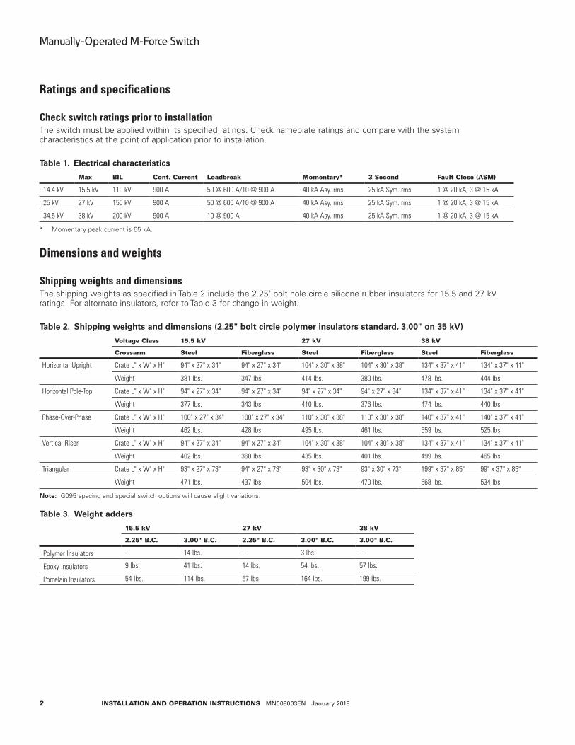
Ratings and specifications
Check switch ratings prior to installation The switch must be applied within its specified ratings. Check nameplate ratings and compare with the system characteristics at the point of application prior to installation.
Table 1 . Electrical characteristics
Max BIl cont. current loadbreak Momentary* 3 second Fault close (asM)
14.4 kV 15.5 kV 110 kV 900 A 50 @ 600 A/10 @ 900 A 40 kA Asy. rms 25 kA Sym. rms 1 @ 20 kA, 3 @ 15 kA
25 kV 27 kV 150 kV 900 A 50 @ 600 A/10 @ 900 A 40 kA Asy. rms 25 kA Sym. rms 1 @ 20 kA, 3 @ 15 kA
34.5 kV 38 kV 200 kV 900 A 10 @ 900 A 40 kA Asy. rms 25 kA Sym. rms 1 @ 20 kA, 3 @ 15 kA
* Momentary peak current is 65 kA.
Dimensions and weights
Shipping weights and dimensionsThe shipping weights as specified in Table 2 include the 2.25" bolt hole circle silicone rubber insulators for 15.5 and 27 kV ratings. For alternate insulators, refer to Table 3 for change in weight.
Table 2 . Shipping weights and dimensions (2 .25" bolt circle polymer insulators standard, 3 .00" on 35 kV)
Voltage class 15.5 kV 27 kV 38 kV
crossarm steel Fiberglass steel Fiberglass steel Fiberglass
Horizontal Upright Crate L" x W" x H" 94" x 27" x 34" 94" x 27" x 34" 104" x 30" x 38" 104" x 30" x 38" 134" x 37" x 41" 134" x 37" x 41"
Weight 381 lbs. 347 lbs. 414 lbs. 380 lbs. 478 lbs. 444 lbs.
Horizontal Pole-Top Crate L" x W" x H" 94" x 27" x 34" 94" x 27" x 34" 94" x 27" x 34" 94" x 27" x 34" 134" x 37" x 41" 134" x 37" x 41"
Weight 377 lbs. 343 lbs. 410 lbs. 376 lbs. 474 lbs. 440 lbs.
Phase-Over-Phase Crate L" x W" x H" 100" x 27" x 34" 100" x 27" x 34" 110" x 30" x 38" 110" x 30" x 38" 140" x 37" x 41" 140" x 37" x 41"
Weight 462 lbs. 428 lbs. 495 lbs. 461 lbs. 559 lbs. 525 lbs.
Vertical Riser Crate L" x W" x H" 94" x 27" x 34" 94" x 27" x 34" 104" x 30" x 38" 104" x 30" x 38" 134" x 37" x 41" 134" x 37" x 41"
Weight 402 lbs. 368 lbs. 435 lbs. 401 lbs. 499 lbs. 465 lbs.
Triangular Crate L" x W" x H" 93" x 27" x 73" 94" x 27" x 73" 93" x 30" x 73" 93" x 30" x 73" 199" x 37" x 85" 99" x 37" x 85"
Weight 471 lbs. 437 lbs. 504 lbs. 470 lbs. 568 lbs. 534 lbs.
Note: G095 spacing and special switch options will cause slight variations.
Table 3 . Weight adders
15.5 kV 27 kV 38 kV
2.25" B.c. 3.00" B.c. 2.25" B.c. 3.00" B.c. 3.00" B.c.
Polymer Insulators – 14 lbs. – 3 lbs. –
Epoxy Insulators 9 lbs. 41 lbs. 14 lbs. 54 lbs. 57 lbs.
Porcelain Insulators 54 lbs. 114 lbs. 57 lbs 164 lbs. 199 lbs.
3
Manually-Operated M-Force Switch
InstallatIon and operatIon InstructIons MN008003EN January 2018
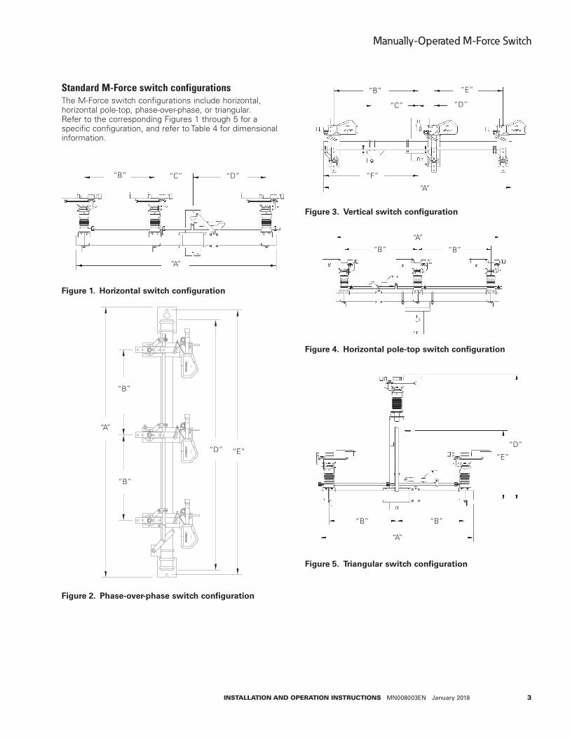
Standard M-Force switch configurationsThe M-Force switch configurations include horizontal, horizontal pole-top, phase-over-phase, or triangular. Refer to the corresponding Figures 1 through 5 for a specific configuration, and refer to Table 4 for dimensional information.
Figure 1 . Horizontal switch configuration
Figure 2 . Phase-over-phase switch configuration
Figure 3 . Vertical switch configuration
Figure 4 . Horizontal pole-top switch configuration
Figure 5 . Triangular switch configuration
“B” “C” “D”
“A”
"B"
"B"
"A"
"D" "E"
“B”
“B”
“A”
“D” “E”
“A”
“E”
“D”“C”
“B”
“F”
“B”“B”
“A”
“B”“B”
“A”
“E”
“D”

4
Manually-Operated M-Force Switch
InstallatIon and operatIon InstructIons MN008003EN January 2018
Table 4 . Dimensional information
dim.
Horizontal Vertical (riser) phase-over-phase triangularstandard G095 standard G09515 kV 25 kV 35 kV 15 kV 25 kV 35 kV 15 kV 25 kV 35 kV 15 kV 25 kV 35 kV 15 kV 25 kV 35 kV 15 kV 25 kV 35 kV
A 79" 88" 119" 97" 108" 126" 79" 88" 97" 108" 119" 126" 95" 104" 126" 61" 73" 79"B 28" 33" 42" 28" 33" 42" 35.5" 40" 45" 49.5" 56" 54.5" 30" 34.5" 45.5" 27" 33" 36"C 15" 15" 18" 24" 24" 24" 19.5" 19.5" 19.5" 19.5" 19.5" 19.5" N/A N/A N/A N/A N/A N/AD 29" 33" 52" 38" 43.5" 52.5" 6.5" 6.5" 6.5" 22" 22.5" 22.5" 88" 97" 119" 58" 61" 73"E N/A N/A N/A N/A N/A N/A 29" 33.5" 45" 29" 33.5" 42" 93" 102" 124" 34" 34" 42"F N/A N/A N/A N/A N/A N/A 39.5" 45" 48.5" 53.5" 59.5" 58" N/A N/A N/A N/A N/A N/AHorizontal Pole-TopStandardDim. 15 kV 25 kV 35 kVA 79" 79" 97"B 36" 36" 45"
5
Manually-Operated M-Force Switch
InstallatIon and operatIon InstructIons MN008003EN January 2018
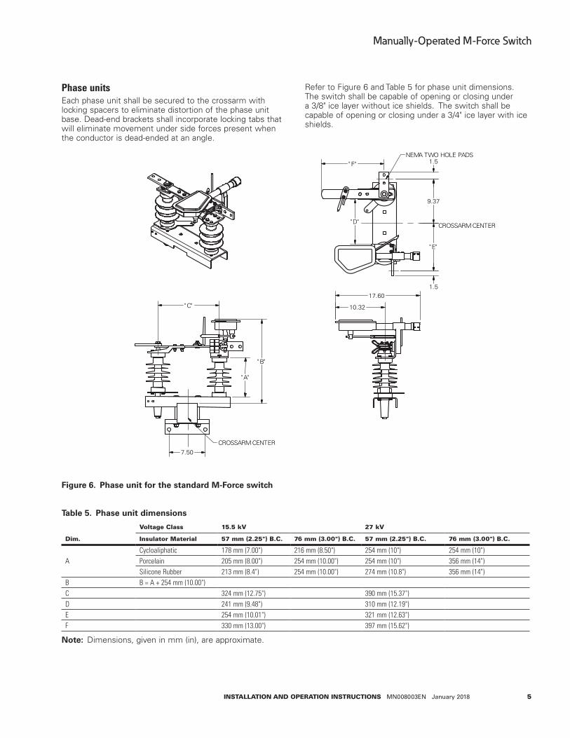
Phase unitsEach phase unit shall be secured to the crossarm with locking spacers to eliminate distortion of the phase unit base. Dead-end brackets shall incorporate locking tabs that will eliminate movement under side forces present when the conductor is dead-ended at an angle.
"C"
"B"
"A"
17.60
10.32
"D"
"E"
9.37
1.5
1.5
7.50
CROSSARM CENTER
CROSSARM CENTER
NEMA TWO HOLE PADS"F"
Figure 6 . Phase unit for the standard M-Force switch
Table 5 . Phase unit dimensions
dim.
Voltage class 15.5 kV 27 kV
Insulator Material 57 mm (2.25") B.c. 76 mm (3.00") B.c. 57 mm (2.25") B.c. 76 mm (3.00") B.c.
ACycloaliphatic 178 mm (7.00") 216 mm (8.50") 254 mm (10") 254 mm (10")Porcelain 205 mm (8.00") 254 mm (10.00") 254 mm (10") 356 mm (14")Silicone Rubber 213 mm (8.4") 254 mm (10.00") 274 mm (10.8") 356 mm (14")
B B = A + 254 mm (10.00")C 324 mm (12.75") 390 mm (15.37")D 241 mm (9.48") 310 mm (12.19")E 254 mm (10.01") 321 mm (12.63")F 330 mm (13.00") 397 mm (15.62")
ote:N Dimensions, given in mm (in), are approximate.
Refer to Figure 6 and Table 5 for phase unit dimensions. The switch shall be capable of opening or closing under a 3/8" ice layer without ice shields. The switch shall be capable of opening or closing under a 3/4" ice layer with ice shields.
6
Manually-Operated M-Force Switch
InstallatIon and operatIon InstructIons MN008003EN January 2018
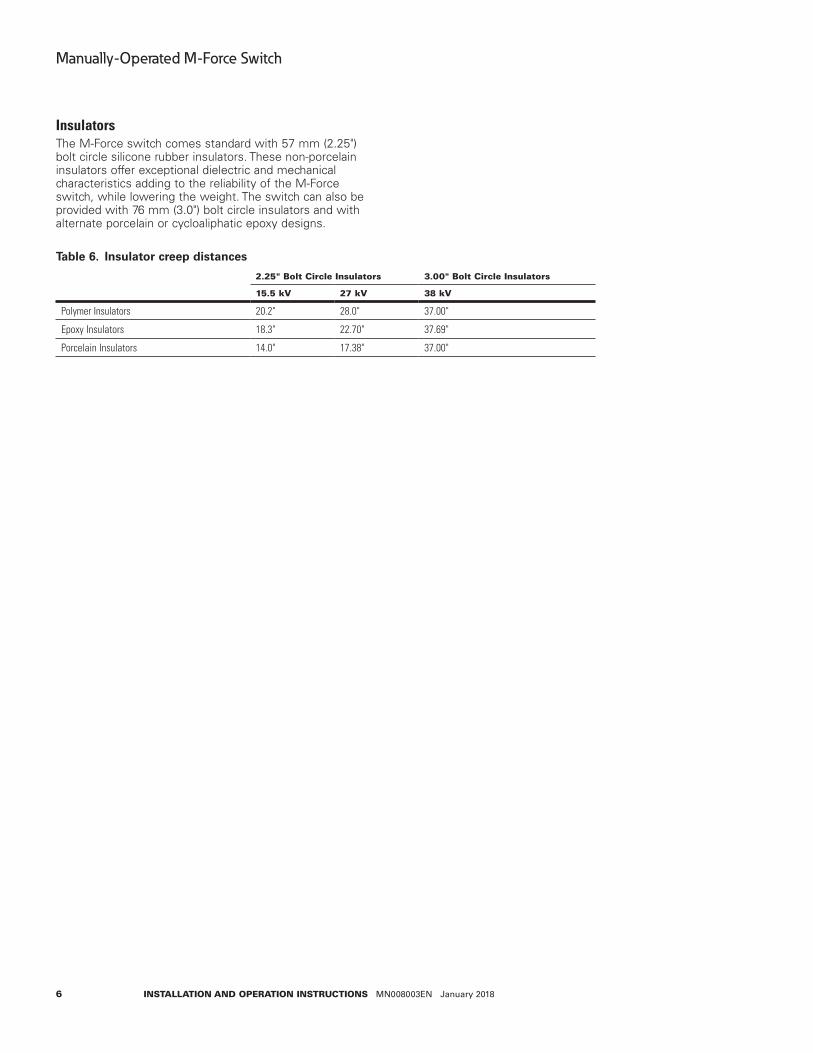
InsulatorsThe M-Force switch comes standard with 57 mm (2.25") bolt circle silicone rubber insulators. These non-porcelain insulators offer exceptional dielectric and mechanical characteristics adding to the reliability of the M-Force switch, while lowering the weight. The switch can also be provided with 76 mm (3.0") bolt circle insulators and with alternate porcelain or cycloaliphatic epoxy designs.
Table 6 . Insulator creep distances
2.25" Bolt circle Insulators 3.00" Bolt circle Insulators
15.5 kV 27 kV 38 kV
Polymer Insulators 20.2" 28.0" 37.00"
Epoxy Insulators 18.3" 22.70" 37.69"
Porcelain Insulators 14.0" 17.38" 37.00"
7
Manually-Operated M-Force Switch
InstallatIon and operatIon InstructIons MN008003EN January 2018
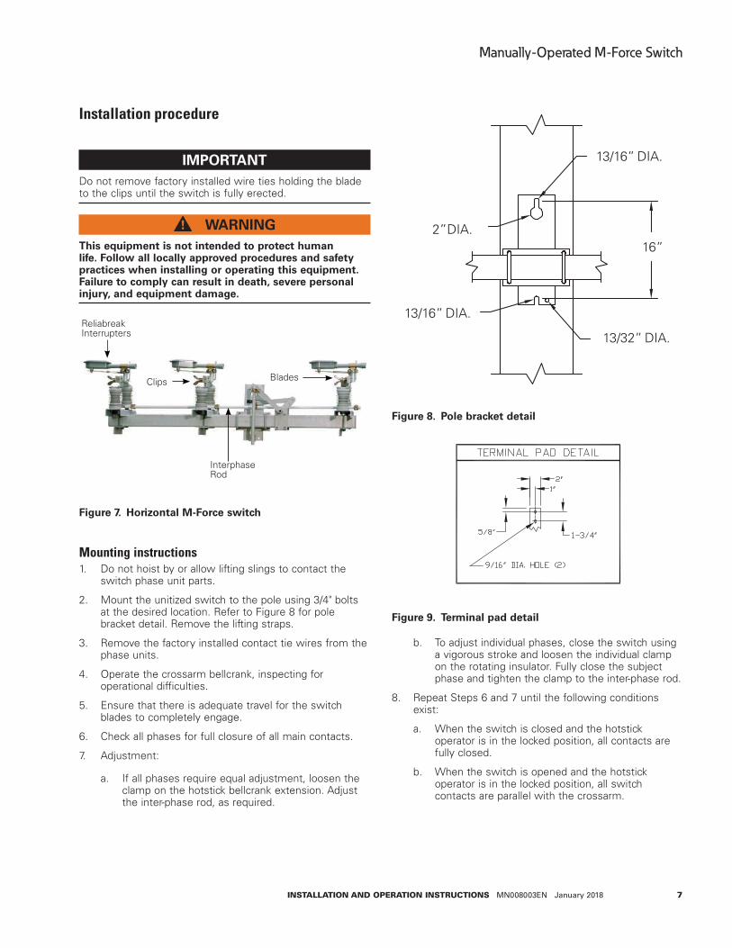
Installation procedure
IMPORTANTDo not remove factory installed wire ties holding the blade to the clips until the switch is fully erected.
WARNINGThis equipment is not intended to protect human life . Follow all locally approved procedures and safety practices when installing or operating this equipment . Failure to comply can result in death, severe personal injury, and equipment damage .
Figure 7 . Horizontal M-Force switch
Mounting instructions1. Do not hoist by or allow lifting slings to contact the
switch phase unit parts.
2. Mount the unitized switch to the pole using 3/4" bolts at the desired location. Refer to Figure 8 for pole bracket detail. Remove the lifting straps.
3. Remove the factory installed contact tie wires from the phase units.
4. Operate the crossarm bellcrank, inspecting for operational difficulties.
5. Ensure that there is adequate travel for the switch blades to completely engage.
6. Check all phases for full closure of all main contacts.
7. Adjustment:
a. If all phases require equal adjustment, loosen the clamp on the hotstick bellcrank extension. Adjust the inter-phase rod, as required.
13/32”
16”
DIA.
DIA.
DIA.2”
13/16”
DIA.13/16”
Figure 8 . Pole bracket detail
Figure 9 . Terminal pad detail
b. To adjust individual phases, close the switch using a vigorous stroke and loosen the individual clamp on the rotating insulator. Fully close the subject phase and tighten the clamp to the inter-phase rod.
8. Repeat Steps 6 and 7 until the following conditions exist:
a. When the switch is closed and the hotstick operator is in the locked position, all contacts are fully closed.
b. When the switch is opened and the hotstick operator is in the locked position, all switch contacts are parallel with the crossarm.
ReliabreakInterrupters
Clips Blades
Interphase Rod
8
Manually-Operated M-Force Switch
InstallatIon and operatIon InstructIons MN008003EN January 2018
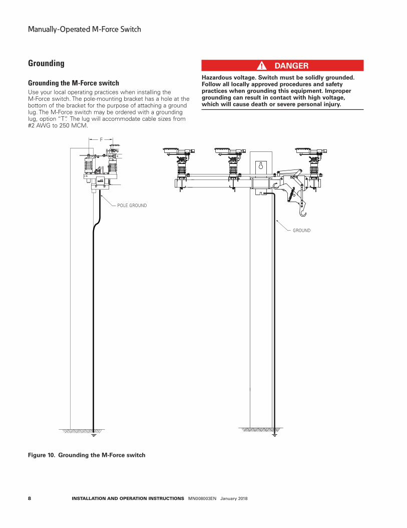
Grounding
Grounding the M-Force switchUse your local operating practices when installing the M-Force switch. The pole-mounting bracket has a hole at the bottom of the bracket for the purpose of attaching a ground lug. The M-Force switch may be ordered with a grounding lug, option “T”. The lug will accommodate cable sizes from #2 AWG to 250 MCM.
GROUND
F
POLE GROUND
Figure 10 . Grounding the M-Force switch
DANGERHazardous voltage . Switch must be solidly grounded . Follow all locally approved procedures and safety practices when grounding this equipment . Improper grounding can result in contact with high voltage, which will cause death or severe personal injury .
9
Manually-Operated M-Force Switch
InstallatIon and operatIon InstructIons MN008003EN January 2018
Switch operation
Manual switch operationote:N Under icy conditions, additional force may be
necessary to fully complete an opening or closing sequence.
WARNINGEquipment misoperation . Never attempt to open an energized M-Force switch giving indication of a partial close operation . In this state, the M-Force switch may not safely interrupt . Failure to comply can result in equipment damage and serious injury .
Hookstick operated
DANGERHazardous voltage . Always use a hotstick when working with this equipment . Failure to do so could result in contact with high voltage, which will cause death or severe personal injury .
IMPORTANTThe hotstick tip must be placed in the groove under the eyelet of the manual operating handle when closing the switch.
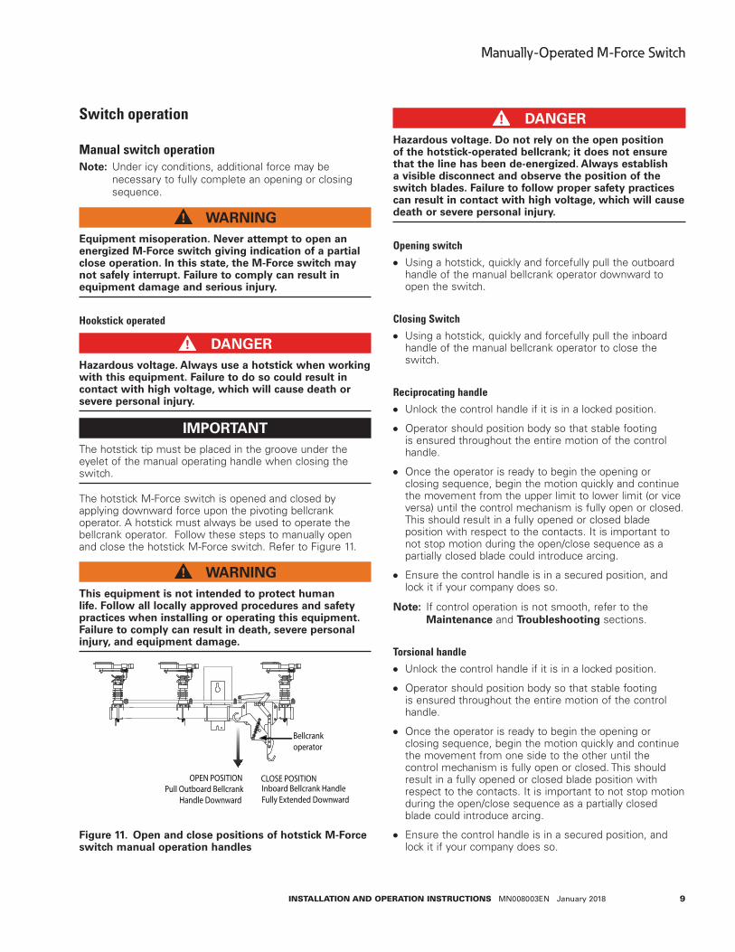
The hotstick M-Force switch is opened and closed by applying downward force upon the pivoting bellcrank operator. A hotstick must always be used to operate the bellcrank operator. Follow these steps to manually open and close the hotstick M-Force switch. Refer to Figure 11.
WARNINGThis equipment is not intended to protect human life . Follow all locally approved procedures and safety practices when installing or operating this equipment . Failure to comply can result in death, severe personal injury, and equipment damage .
Inboard Bellcrank HandleFully Extended Downward
OPEN POSITION
Bellcrankoperator
CLOSE POSITIONPull Outboard Bellcrank
Handle Downward
Figure 11 . Open and close positions of hotstick M-Force switch manual operation handles
DANGERHazardous voltage . Do not rely on the open position of the hotstick-operated bellcrank; it does not ensure that the line has been de-energized . Always establish a visible disconnect and observe the position of the switch blades . Failure to follow proper safety practices can result in contact with high voltage, which will cause death or severe personal injury .
Opening switch Using a hotstick, quickly and forcefully pull the outboard
handle of the manual bellcrank operator downward to open the switch.
Closing Switch Using a hotstick, quickly and forcefully pull the inboard
handle of the manual bellcrank operator to close the switch.
Reciprocating handle Unlock the control handle if it is in a locked position.
Operator should position body so that stable footing is ensured throughout the entire motion of the control handle.
Once the operator is ready to begin the opening or closing sequence, begin the motion quickly and continue the movement from the upper limit to lower limit (or vice versa) until the control mechanism is fully open or closed. This should result in a fully opened or closed blade position with respect to the contacts. It is important to not stop motion during the open/close sequence as a partially closed blade could introduce arcing.
Ensure the control handle is in a secured position, and lock it if your company does so.
ote:N If control operation is not smooth, refer to the Maintenance and Troubleshooting sections.
Torsional handle Unlock the control handle if it is in a locked position.
Operator should position body so that stable footing is ensured throughout the entire motion of the control handle.
Once the operator is ready to begin the opening or closing sequence, begin the motion quickly and continue the movement from one side to the other until the control mechanism is fully open or closed. This should result in a fully opened or closed blade position with respect to the contacts. It is important to not stop motion during the open/close sequence as a partially closed blade could introduce arcing.
Ensure the control handle is in a secured position, and lock it if your company does so.
10
Manually-Operated M-Force Switch
InstallatIon and operatIon InstructIons MN008003EN January 2018
ote:N If control operation is not smooth, refer to the Maintenance and Troubleshooting sections.
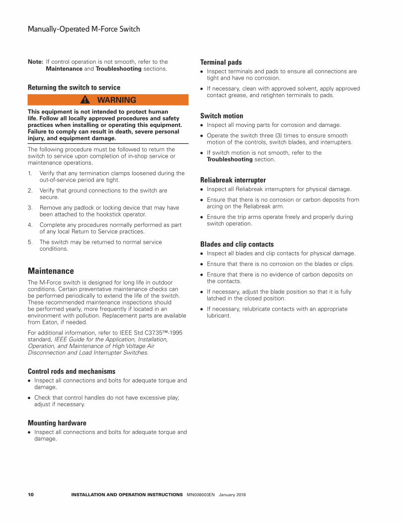
Returning the switch to service
WARNINGThis equipment is not intended to protect human life . Follow all locally approved procedures and safety practices when installing or operating this equipment . Failure to comply can result in death, severe personal injury, and equipment damage .
The following procedure must be followed to return the switch to service upon completion of in-shop service or maintenance operations.
1. Verify that any termination clamps loosened during the out-of-service period are tight.
2. Verify that ground connections to the switch are secure.
3. Remove any padlock or locking device that may have been attached to the hookstick operator.
4. Complete any procedures normally performed as part of any local Return to Service practices.
5. The switch may be returned to normal service conditions.
MaintenanceThe M-Force switch is designed for long life in outdoor conditions. Certain preventative maintenance checks can be performed periodically to extend the life of the switch. These recommended maintenance inspections should be performed yearly, more frequently if located in an environment with pollution. Replacement parts are available from Eaton, if needed.
For additional information, refer to IEEE Std C37.35™-1995 standard, IEEE Guide for the Application, Installation, Operation, and Maintenance of High Voltage Air Disconnection and Load Interrupter Switches.
Control rods and mechanisms Inspect all connections and bolts for adequate torque and
damage.
Check that control handles do not have excessive play; adjust if necessary.
Mounting hardware Inspect all connections and bolts for adequate torque and
damage.
Terminal pads Inspect terminals and pads to ensure all connections are
tight and have no corrosion.
If necessary, clean with approved solvent, apply approved contact grease, and retighten terminals to pads.
Switch motion Inspect all moving parts for corrosion and damage.
Operate the switch three (3) times to ensure smooth motion of the controls, switch blades, and interrupters.
If switch motion is not smooth, refer to the Troubleshooting section.
Reliabreak interrupter Inspect all Reliabreak interrupters for physical damage.
Ensure that there is no corrosion or carbon deposits from arcing on the Reliabreak arm.
Ensure the trip arms operate freely and properly during switch operation.
Blades and clip contacts Inspect all blades and clip contacts for physical damage.
Ensure that there is no corrosion on the blades or clips.
Ensure that there is no evidence of carbon deposits on the contacts.
If necessary, adjust the blade position so that it is fully latched in the closed position.
If necessary, relubricate contacts with an appropriate lubricant.
11
Manually-Operated M-Force Switch
InstallatIon and operatIon InstructIons MN008003EN January 2018
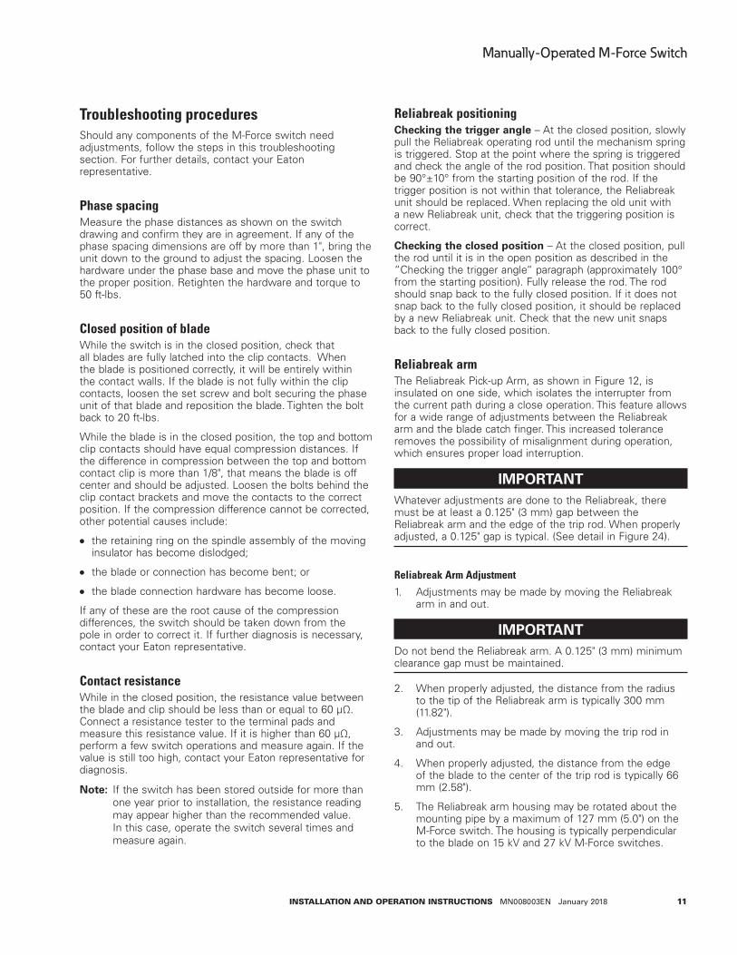
Troubleshooting proceduresShould any components of the M-Force switch need adjustments, follow the steps in this troubleshooting section. For further details, contact your Eaton representative.
Phase spacingMeasure the phase distances as shown on the switch drawing and confirm they are in agreement. If any of the phase spacing dimensions are off by more than 1", bring the unit down to the ground to adjust the spacing. Loosen the hardware under the phase base and move the phase unit to the proper position. Retighten the hardware and torque to 50 ft-lbs.
Closed position of bladeWhile the switch is in the closed position, check that all blades are fully latched into the clip contacts. When the blade is positioned correctly, it will be entirely within the contact walls. If the blade is not fully within the clip contacts, loosen the set screw and bolt securing the phase unit of that blade and reposition the blade. Tighten the bolt back to 20 ft-lbs.
While the blade is in the closed position, the top and bottom clip contacts should have equal compression distances. If the difference in compression between the top and bottom contact clip is more than 1/8", that means the blade is off center and should be adjusted. Loosen the bolts behind the clip contact brackets and move the contacts to the correct position. If the compression difference cannot be corrected, other potential causes include:
the retaining ring on the spindle assembly of the moving insulator has become dislodged;
the blade or connection has become bent; or
the blade connection hardware has become loose.
If any of these are the root cause of the compression differences, the switch should be taken down from the pole in order to correct it. If further diagnosis is necessary, contact your Eaton representative.
Contact resistanceWhile in the closed position, the resistance value between the blade and clip should be less than or equal to 60 µΩ. Connect a resistance tester to the terminal pads and measure this resistance value. If it is higher than 60 µΩ, perform a few switch operations and measure again. If the value is still too high, contact your Eaton representative for diagnosis.
ote:N If the switch has been stored outside for more than one year prior to installation, the resistance reading may appear higher than the recommended value. In this case, operate the switch several times and measure again.
Reliabreak positioningChecking the trigger angle – At the closed position, slowly pull the Reliabreak operating rod until the mechanism spring is triggered. Stop at the point where the spring is triggered and check the angle of the rod position. That position should be 90°±10° from the starting position of the rod. If the trigger position is not within that tolerance, the Reliabreak unit should be replaced. When replacing the old unit with a new Reliabreak unit, check that the triggering position is correct.
Checking the closed position – At the closed position, pull the rod until it is in the open position as described in the “Checking the trigger angle“ paragraph (approximately 100° from the starting position). Fully release the rod. The rod should snap back to the fully closed position. If it does not snap back to the fully closed position, it should be replaced by a new Reliabreak unit. Check that the new unit snaps back to the fully closed position.
Reliabreak armThe Reliabreak Pick-up Arm, as shown in Figure 12, is insulated on one side, which isolates the interrupter from the current path during a close operation. This feature allows for a wide range of adjustments between the Reliabreak arm and the blade catch finger. This increased tolerance removes the possibility of misalignment during operation, which ensures proper load interruption.
IMPORTANTWhatever adjustments are done to the Reliabreak, there must be at least a 0.125" (3 mm) gap between the Reliabreak arm and the edge of the trip rod. When properly adjusted, a 0.125" gap is typical. (See detail in Figure 24).
Reliabreak Arm Adjustment
1. Adjustments may be made by moving the Reliabreak arm in and out.
IMPORTANTDo not bend the Reliabreak arm. A 0.125" (3 mm) minimum clearance gap must be maintained.
2. When properly adjusted, the distance from the radius to the tip of the Reliabreak arm is typically 300 mm (11.82").
3. Adjustments may be made by moving the trip rod in and out.
4. When properly adjusted, the distance from the edge of the blade to the center of the trip rod is typically 66 mm (2.58").
5. The Reliabreak arm housing may be rotated about the mounting pipe by a maximum of 127 mm (5.0") on the M-Force switch. The housing is typically perpendicular to the blade on 15 kV and 27 kV M-Force switches.
12
Manually-Operated M-Force Switch
InstallatIon and operatIon InstructIons MN008003EN January 2018
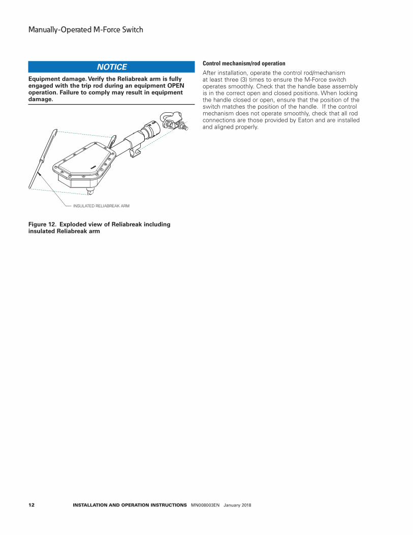
NOTICEEquipment damage . Verify the Reliabreak arm is fully engaged with the trip rod during an equipment OPEN operation . Failure to comply may result in equipment damage .
INSULATED RELIABREAK ARM
Figure 12 . Exploded view of Reliabreak including insulated Reliabreak arm
Control mechanism/rod operation
After installation, operate the control rod/mechanism at least three (3) times to ensure the M-Force switch operates smoothly. Check that the handle base assembly is in the correct open and closed positions. When locking the handle closed or open, ensure that the position of the switch matches the position of the handle. If the control mechanism does not operate smoothly, check that all rod connections are those provided by Eaton and are installed and aligned properly.
13
Manually-Operated M-Force Switch
InstallatIon and operatIon InstructIons MN008003EN January 2018
Reliabreak Replacement Instructions
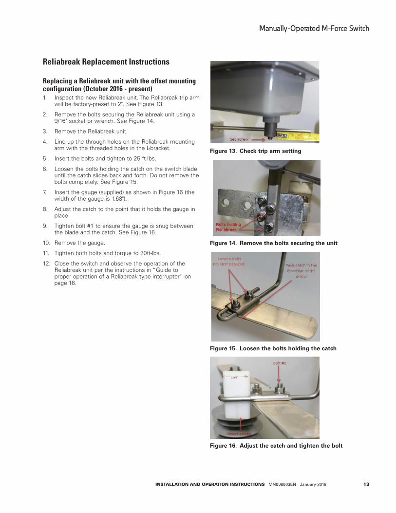
Replacing a Reliabreak unit with the offset mounting configuration (October 2016 - present)1. Inspect the new Reliabreak unit. The Reliabreak trip arm
will be factory-preset to 2". See Figure 13.
2. Remove the bolts securing the Reliabreak unit using a 9/16" socket or wrench. See Figure 14.
3. Remove the Reliabreak unit.
4. Line up the through-holes on the Reliabreak mounting arm with the threaded holes in the L-bracket.
5. Insert the bolts and tighten to 25 ft-lbs.
6. Loosen the bolts holding the catch on the switch blade until the catch slides back and forth. Do not remove the bolts completely. See Figure 15.
7. Insert the gauge (supplied) as shown in Figure 16 (the width of the gauge is 1.68").
8. Adjust the catch to the point that it holds the gauge in place.
9. Tighten bolt #1 to ensure the gauge is snug between the blade and the catch. See Figure 16.
10. Remove the gauge.
11. Tighten both bolts and torque to 20ft-lbs.
12. Close the switch and observe the operation of the Reliabreak unit per the instructions in “Guide to proper operation of a Reliabreak type interrupter“ on page 16.
Figure 13 . Check trip arm setting
Figure 14 . Remove the bolts securing the unit
Figure 15 . Loosen the bolts holding the catch
Figure 16 . Adjust the catch and tighten the bolt

14
Manually-Operated M-Force Switch
InstallatIon and operatIon InstructIons MN008003EN January 2018
Replacing a Reliabreak unit with a U-bolt and mounting pipe configuration (pre-2015 version)1. Loosen the nut as shown in Figure 17.
2. Slide the Reliabreak off the bolt. If the U-clamp has not been damaged, leave it in place.
3. Slide the replacement unit onto the bolt and torque the nut to 25 ft-lbs. See Figure 12.
4. Double check the adjustment per the instructions in “Guide to proper operation of a Reliabreak type interrupter“ on page 16.
5. If the U-clamp has been damaged and requires replacement, loosen the two bolts and remove the clamp. Mark the location of the clamp on the pipe.
6. Attach the new clamp and torque to 25 ft-lbs.
ote:N The casting must be located flush with the top of the pipe. See Figure 18.
7. Make adjustments per the instructions in “Guide to proper operation of a Reliabreak type interrupter“ on page 16.
Figure 17 . Loosen the nut on the Reliabreak
Figure 18 . Attach the new clamp
15
Manually-Operated M-Force Switch
InstallatIon and operatIon InstructIons MN008003EN January 2018
DANGERHazardous voltage . Contact with hazardous voltage will cause severe injury or death . Follow all locally approved safety procedures when working around high- and low-voltage lines and equipment .
Converting a shared bolt mounting to current offset mounting configuration (April 2015 - October 2016)
ote:N To perform this replacement, the switch must be in the open position.
1. De-energize the switch on both the line and load sides.
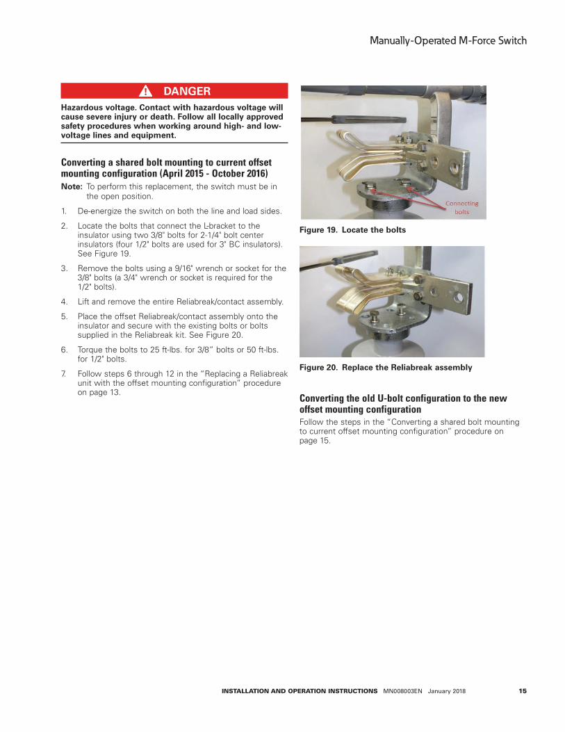
2. Locate the bolts that connect the L-bracket to the insulator using two 3/8" bolts for 2-1/4" bolt center insulators (four 1/2" bolts are used for 3" BC insulators).See Figure 19.
3. Remove the bolts using a 9/16" wrench or socket for the 3/8" bolts (a 3/4" wrench or socket is required for the 1/2" bolts).
4. Lift and remove the entire Reliabreak/contact assembly.
5. Place the offset Reliabreak/contact assembly onto the insulator and secure with the existing bolts or bolts supplied in the Reliabreak kit. See Figure 20.
6. Torque the bolts to 25 ft-lbs. for 3/8” bolts or 50 ft-lbs. for 1/2" bolts.
7. Follow steps 6 through 12 in the “Replacing a Reliabreak unit with the offset mounting configuration” procedure on page 13.
Figure 19 . Locate the bolts
Figure 20 . Replace the Reliabreak assembly
Converting the old U-bolt configuration to the new offset mounting configurationFollow the steps in the “Converting a shared bolt mounting to current offset mounting configuration” procedure on page 15.
16
Manually-Operated M-Force Switch
InstallatIon and operatIon InstructIons MN008003EN January 2018
Guide to proper operation of a Reliabreak type interrupter
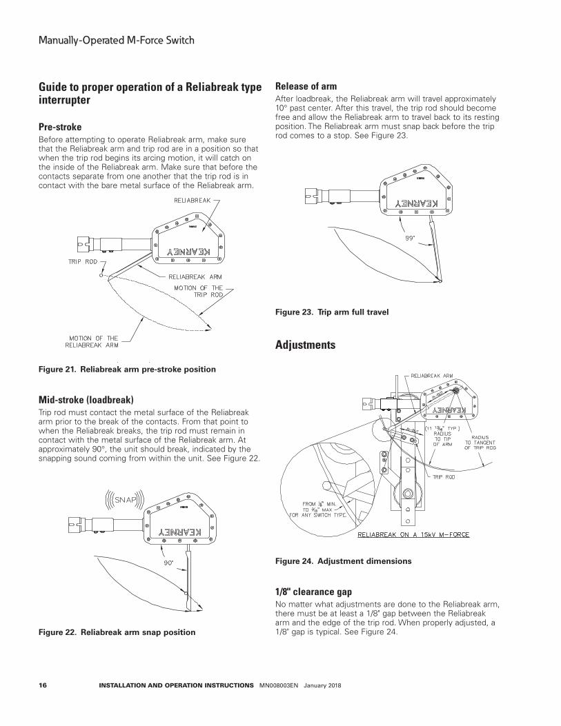
Pre-strokeBefore attempting to operate Reliabreak arm, make sure that the Reliabreak arm and trip rod are in a position so that when the trip rod begins its arcing motion, it will catch on the inside of the Reliabreak arm. Make sure that before the contacts separate from one another that the trip rod is in contact with the bare metal surface of the Reliabreak arm.
Figure 21 . Reliabreak arm pre-stroke position
Mid-stroke (loadbreak)Trip rod must contact the metal surface of the Reliabreak arm prior to the break of the contacts. From that point to when the Reliabreak breaks, the trip rod must remain in contact with the metal surface of the Reliabreak arm. At approximately 90°, the unit should break, indicated by the snapping sound coming from within the unit. See Figure 22.
Figure 22 . Reliabreak arm snap position
Release of armAfter loadbreak, the Reliabreak arm will travel approximately 10° past center. After this travel, the trip rod should become free and allow the Reliabreak arm to travel back to its resting position. The Reliabreak arm must snap back before the trip rod comes to a stop. See Figure 23.
Figure 23 . Trip arm full travel
Adjustments
Figure 24 . Adjustment dimensions
1/8" clearance gapNo matter what adjustments are done to the Reliabreak arm, there must be at least a 1/8" gap between the Reliabreak arm and the edge of the trip rod. When properly adjusted, a 1/8" gap is typical. See Figure 24.
17
Manually-Operated M-Force Switch
InstallatIon and operatIon InstructIons MN008003EN January 2018
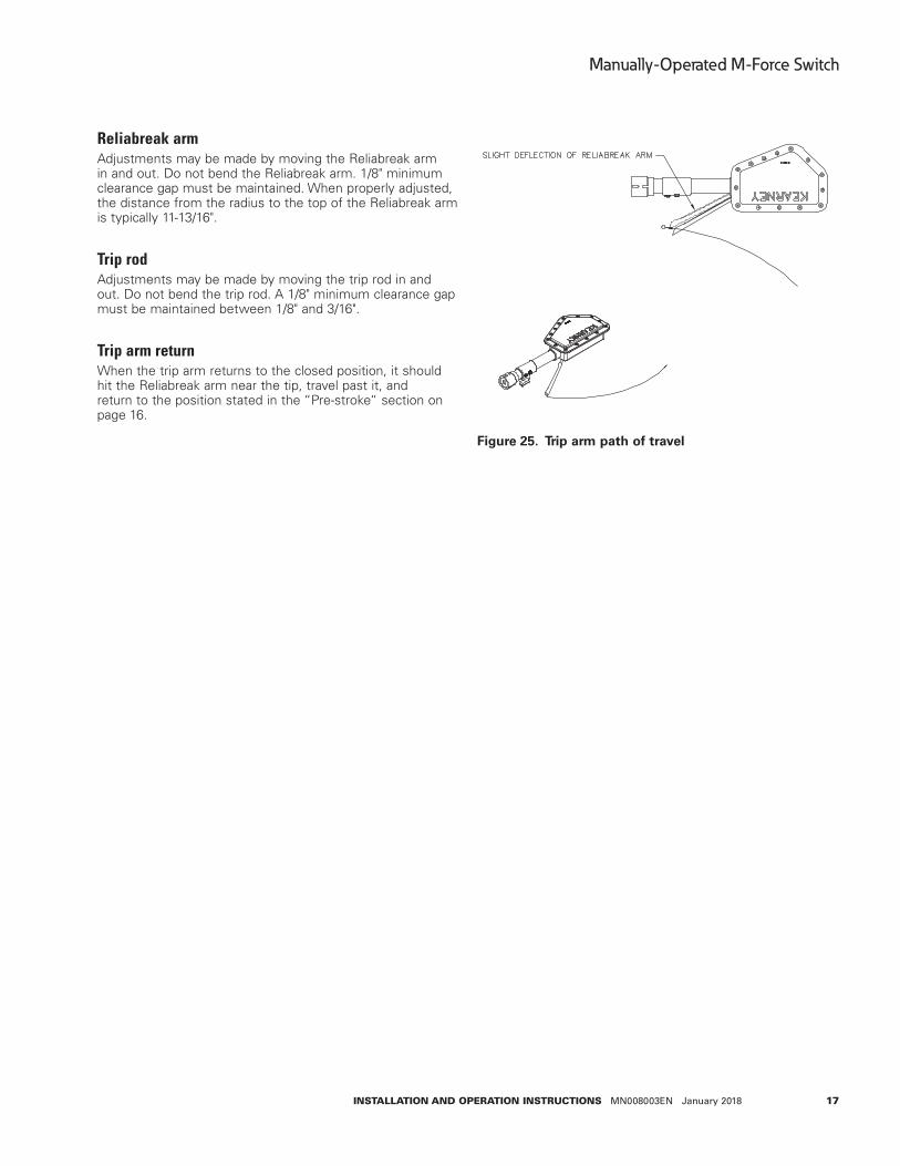
Reliabreak armAdjustments may be made by moving the Reliabreak arm in and out. Do not bend the Reliabreak arm. 1/8" minimum clearance gap must be maintained. When properly adjusted, the distance from the radius to the top of the Reliabreak arm is typically 11-13/16".
Trip rodAdjustments may be made by moving the trip rod in and out. Do not bend the trip rod. A 1/8" minimum clearance gap must be maintained between 1/8" and 3/16".
Trip arm returnWhen the trip arm returns to the closed position, it should hit the Reliabreak arm near the tip, travel past it, and return to the position stated in the “Pre-stroke“ section on page 16.
Figure 25 . Trip arm path of travel

Eaton1000 Eaton BoulevardCleveland, OH 44122United StatesEaton.com
Eaton’s Power Systems Division2300 Badger DriveWaukesha, WI 53188United StatesEaton.com/cooperpowerseries
© 2018 EatonAll Rights ReservedPrinted in USAPublication No. MN008003EN Rev. 02January 2018
Eaton is a registered trademark.
All trademarks are property of their respective owners.
For Eaton‘s Cooper Power series product information, call 1-877-277-4636 or visit: www.eaton.com/cooperpowerseries.
!SAFETYFOR LIFE