manuale uso e manutenzione operating and … srl via bizzarri, 6 - 40012 calderara di reno - bologna...
TRANSCRIPT
07/16Tramec srl Via Bizzarri, 6 - 40012 Calderara di Reno - Bologna - ItalyTel. +39 051 728935 - Fax +39 051 728937 - [email protected]
Manuale uso e ManutenzioneOperating and Maintenance
1
INDICE INDEX INHALTSVERZEICHNIS Pag.PageSeite
1 AVVERTENZE GENERALI SULLA SICUREZZA GENERAL SAFETY GUIDELINES ALLGEMEINE SICHERHEITSHINWEISE 32 STATO DI FORNITURA CONDITIONS OF SUPPLY LIEFERBEDINGUNGEN 53 INSTALLAZIONE INSTALLATION INSTALLATION 84 LUBRIFICAZIONE LUBRICATION SCHMIERUNG 145 MESSA IN SERVIZIO / Rischi residui STARTING-UP / Residual risks INBETRIEBNAHME / Restgefahr 226 MANUTENZIONE MAINTENANCE INSTANDHALTUNG 23
7 LISTA PARTI DI RICAMBIO RIDUTTORI A INGRANAGGI SPARE PARTS LIST HELICAL AND BEVEL HELICALGEARBOXES ERSATZTEILLISTE UNTERSETZUNGSGETRIEBE 24
TA/TF 56B - TA/TF 63B 24
TA/TF 56C - TA/TF 63C 26
TA..B - TC..B - TF..B 28
TA..C - TC..C - TF..C 30
TA..B - TC..B - TF..B - TA..C - TC..C - TF..C (Dispositivo antiritorno - Backstop device - Rücklaufsperre) 32
ZA..A 34
ZA..B - ZF..B 36
ZA..C - ZF..C 38
ZA..B - ZF..B - ZA..C - ZF..C (Dispositivo antiritorno - Backstop device - Rücklaufsperre) 40
PA..A 42
PA..B - PC..B 44
PA..B (Dispositivo antiritorno - Backstop device - Rücklaufsperre) 46
MA..B 48
MA..B (Dispositivo antiritorno - Backstop device - Rücklaufsperre) 50
RA - RC - RF (in = 1) 52
RA - RC - RF (in > 1) 54
RA - RC - RF (in = 1) s.e. 56
RA - RC - RF (in > 1) s.e. 58
LA - LC - LF (in = 1) 60
LA - LC - LF (in > 1) 62
LA - LC - LF (in = 1) s.e. 64
LA - LC - LF (in > 1) s.e. 66
2
INDICE INDEX INHALTSVERZEICHNIS Pag.PageSeite
LISTA PARTI DI RICAMBIO RIDUTTORI A VITE SENZA FINE SPARE PARTS LIST WORM GEARBOXES ERSATZTEILLISTE UNTERSETZUNGSGETRIEBE
XA - XF 68
XC 70
KC 72
HA - HF 74
KXC -XXC - XXA - XXF - KKC 76
X.-H.-K.-XX.-KX.-KK. (Dispositivo limitatore di coppia - Torque limiter device - Rutschkupplungvorrichtung) 78
SFK - SRK - SCFK -SCRK 80
SCFK -SCRK 82
SFK -SRK - SCFK - SCRK (Dispositivo limitatore di coppia - Torque limiter device - Rutschkupplungvorrichtung) 84
BFK - BRK - BCFK -BCRK 86
BCFK -BCRK 88
BFK - BRK - BCFK - BCRK (Dispositivo limitatore di coppia - Torque limiter device - Rutschkupplungvorrichtung) 90
VM 135 92
VM 150 94
VM 170 96
VM 230 98
8 Condizioni generali di garanzia General conditional of warranty Allgemeine garantiebedingungen 100
3
1.0 AVVERTENZE GENERALI SULLA SICUREZZA 1.0 GENERAL SAFETY GUIDELINES
Tramec gearboxes are in compliancewith machinery direc-tive 2006/42 EC and are identified as partly completed ma-chinery (Annex II-B). Tramec gearboxes are supplied with a declaration of incorporation. The official language of the in-structions for use, assembly and maintenance is english. It is absolutely forbidden to use standard gearboxes is explosive atmospheres. Standard gearboxes cannot be used in environ-ments which are classified in the atex directive.All given instructions refer to the use of reducers and gear mo-tors, which must be handled, installed, started and serviced by qualified personnel (in compliance with standard IEC 364) who are fully familiar with the content of this manual.
Additional information, to be applied for if not available, shall be given for special parts.Please also comply with:
● given safety symbols on reducer and/or motor labels
● system operating instructions
● applicable standards for installation
● current laws on safety
All reducers and gear motors mentioned in this manual are intended for industrial use and operation at a room tempera-ture between -20°C and +40°C, at an altitude of max. 1000 m above sea level.Please comply with the instructions given in the pertaining manuals when installing electric motors, variable speed mo-tors, inverters, etc... Please apply for manuals if not avail-able.Technical data and information concerning operating condi-tions of reducers and gearmotors are reported on identifica-tion plates and in technical catalogues.
In case of different uses, the chief installer shall take all nec-essary additional measures to ensure safe operating condi-tions.
Standard reducers and gear motors cannot be operated in:
● salty environments
● inflamable environments or products
● highly humid environments
● in the presence of fluids or fully immersed
1.0 ALLGEMEINE SICHERHEITSHINWEISE
Tramec getribe entsprechen der richtlinie fur maschinen 2006/42 EG und werden als unvollstndige maschinen identifi-ziert (Anhang IIB). Tramec getriebe werden mit erklarung des herstellers geliefert. Die offizielle sprache der anweisungen fur montage, betrieb und wartung ist englisch. Die anwen-dung von standard-getriebe in atex klassifierten bereichen ist absolut verboten. Alle nachstehenden Warnhinweise bezie-hen sich auf den Einsatz von Getrieben und Getriebemotoren, deren Bewegung, Installation, Anlass, Instandhaltung und Re-paratur von Fachpersonal durchgeführt werden sollen (gemäß IEC 364), das Kenntnis über die im vorliegenden Handbuch enthaltenen Informationen hat.Falls vorhanden, werden spezielle Komponenten mit zusätzlichen Informationen ausgestattet (falls nicht vorhanden, bitte anfordern).Darüber hinaus wird eingehend darauf hingewiesen, sich an folgendes zu halten:
● an die eventuell auf den Aufklebern der Getriebe und/oder Motoren angegebenen Sicherheitssymbole;
● an die Anleitungen, die sich auf die Anlage beziehen;
● an die im Hinblick auf die korrekte Installation applizierten Richtlinien;
● an die geltenden gesetzlichen Sicherheitsvorschriften
Alle im vorliegenden Handbuch angegebenen Getriebe und Getriebemotoren sind für industriellen Einsatz in einer Umge-bungstemperatur von -20°C bis +40°C und in einer max. Höhe von 1000 m über dem Meeresspiegel vorgesehen.Für die Installation von Elektromotoren, Verstellgetrieben, Frequenzumrichtern, usw. muss man sich an die Anweisun-gen in den entsprechenden Unterlagen (falls nicht vorhanden, bitte anfordern) halten.Die technischen Daten und die Informationen zu den Einsatz-bedingungen der Getriebe und Getriebemotoren werden auf den Typenschildern und in den jeweiligen technischen Katalo-gen wiedergegeben.Sollten anderweitige Einsätze vorgesehen sein, muss der Verantwortliche für die Installation zusätzliche Schutzmaß-nahmen treffen und sie entsprechend garantieren.Der Einsatz der Getriebe und Getriebemotoren in ihrer Stan-dardausführung ist unter folgenden Bedingungen nicht gestattet:
● in salzhaltiger Umgebung
● in aggressiver Atmosphäre mit Explosionsgefahr
● in einer besonders feuchten Umgebung
● bei Vorhandensein von Flüssigkeiten oder im Tauchbetrieb
I riduttori Tramec sono conformi alla direttiva macchine 2006/42 CE,sono identificati come quasi macchine (all-IIB). I riduttori saranno accompagnati da una dichiarazione di in-corporazione. La lingua ufficiale delle istruzioni per l’uso, l’as-semblaggio, la manutenzione è l’inglese. Divieto assoluto di usare i riduttori standard in ambienti esplosivi, solo ambienti non classificati.
Tutte le seguenti avvertenze sono riferite all’utilizzo di riduttori e motoriduttori, pertanto tutte le attività relative alla movimen-tazione, installazione, avviamento, manutenzione e riparazio-ne debbono essere effettuate da personale qualificato (defini-to secondo IEC 364) che sia a conoscenza delle informazioni contenute nel presente manuale. Eventuali componenti speciali saranno corredati di informa-zioni aggiuntive (da richiedere se non disponibili).Si raccomanda inoltre di attenersi:
● a eventuali simboli inerenti la sicurezza indicati su etichette adesive sui riduttori e/o motori
● alle istruzioni relative all’impianto
● alle normative applicabili per una corretta installazione
● alle vigenti disposizioni legislative relative alla sicurezza
Tutti i riduttori e motoriduttori citati nel presente manuale sono destinati ad un impiego industriale con temperatura ambiente da -20°C a +40°C ad una altitudine max di 1000 m slm.
Per l’installazione di motori elettrici, motovariatori, inverter, ecc. attenersi alle disposizioni riportate nella relativa docu-mentazione (da richiedere se non disponibile).
I dati tecnici e le informazioni relative alle condizioni di utilizzo dei riduttori e motoriduttori sono indicate sulle targhette e sui rispettivi cataloghi tecnici.
Se previsti impieghi diversi, il responsabile dell’installazione dovrà adottare e garantire eventuali protezioni supplementari che dovessero rendersi necessarie.
Non è consentito l’impiego dei riduttori e motoriduttori standard in:
● ambienti salini
● atmosfere aggressive con pericolo di esplosione
● ambienti con elevata percentuale di umidità
● ambienti fluidi o in totale immersione
4
Prior written authorization is needed if the reducers or the gear motors are to be installed in lifts or other apparatuses for the transportation of people.
Reducers and gear motors may be a danger to the operator due to:
● moving parts whilst the machine is in operation
● surfaces with temperatures exceeding 50°C
● live electrical parts (in electric motors)
If reducers or gear motors need to be either adjusted or ser-viced, please ensure that:
● the machine is stopped
● motor and auxiliary devices are disconnected from the mains
● safety devices preventing undesired starts are enabled
● mechanical devices for blocking the load are enabled. They will obviously have to be disabled before restarting the machine.
Caution!
People may be seriously injured or damage may occur to equipment in case of:
● Improper use
● Incorrect installation
● Removal of safety devices
● couplers not properly connected
● Failure to carry out regular checks
● Failure to carry out servicing
Stop the machine and perform necessary checks in case of:
● excessively high temperature
● excessive noise coming from the machine
● vibrations
Für den Einsatz der Getriebe und Getriebemotoren in Fahr-stuhle oder anderen Einrichtungen für den Personentransport ist eine schriftliche Genehmigung erforderlich.
Getriebe und Getriebemotoren können aufgrund folgender Vorfaelle Gefahr für den Bediener darstellen:
● sich während des Betriebs bewegenden Teile
● Flächen mit Temperaturen über 50°C
● unter Spannung stehende Teile (bei Elektromotoren)
Im Falle von Einstellung, Instandhaltung oder Reparatur an den Getrieben und Getriebemotoren muss es unbedingt über-prüft werden, dass:
● die Maschine sich im Stillstand befindet;
● der Motor und eventuelle Hilfsvorrichtungen vom Stromnetz getrennt sind;
● Sicherheitsvorrichtungen, die einen plötzlichen bzw. unerwünschten Anlauf verhindern, aktiviert sind;
● mechanische Lastenblockierungsvorrichtungen aktiviert sind (diese müssen natürlich vor der Inbetriebsetzung der Maschine ausgeschaltet werden).
Achtung!
Schwere Personen-oder Anlageschäden können durch folgendes verursacht werden:
● unangemessener Einsatz
● fehlerhafte Installation
● Abnahme der Schutzvorrichtungen
● fehlerhafte Verbindung an die Anschlussorgane
● mangelnde Ausführung der regelmäßigen Kontrollen
● keinerlei Instandhaltung
Die Maschine muss beim Vorliegen folgender Anomalien an-gehalten und entsprechend überprüft werden:
● übermäßiger Temperaturanstieg
● erhöhter Geräuschpegel
● Vibrationen
È richiesta l'autorizzazione scritta per l'utilizzo dei riduttori e motoriduttori nelle applicazioni riguardanti il sollevamento di ascensori o altri dispositivi utilizzati per lo spostamento di per-sone. I riduttori e motoriduttori possono presentare situazioni di pe-ricolo per l'operatore dovute a:
● parti in movimento durante il funzionamento
● superfici con temperature superiori a 50°C
● parti sotto tensione (nei motori elettrici)
Qualora sia necessario effettuare interventi sui riduttori e mo-toriduttori di messa a punto, manutenzione, riparazione, è in-dispensabile accertare che:
● la macchina sia ferma
● il motore ed eventuali dispositivi ausiliari siano scollegati dall'alimentazione di rete
● siano attivati i dispositivi di sicurezza che impediscono avviamenti involontari
● eventuali dispositivi meccanici di blocco del carico siano attivi (ovviamente dovranno essere disinseriti prima della messa in funzione della macchina)
Attenzione!
Possono verificarsi danni gravi a persone o a impianti a causa di:
● Utilizzo improprio
● installazione non corretta
● rimozione delle protezioni
● imperfetta connessione ad organi di collegamento
● mancanza di verifiche periodiche
● assenza di manutenzione
Arrestare la macchina e procedere alle opportune verifiche se si dovessero riscontrare le seguenti anomalìe:
● aumento eccessivo della temperatura
● rumorosità eccessiva
● vibrazioni
5
2.0 STATO DI FORNITURA 2.0 CONDITIONS OF SUPPLYGoods receiptOn receipt of reducers and gear motors always check for transport damage. Never install a damaged unit and report the detected defect to the forwarding agent.
PackingPacking may differ depending on product quantity and size. Unless otherwise agreed, goods will be packed either on pal-let wrapped with polyethylene film, taped and strapped or packed on case pallet or simply in cartons.If necessary reducers shall be separated using proper mate-rial such as foam, paper, cardboard and so forth.Packing materials should be disposed of in compliance with current laws.
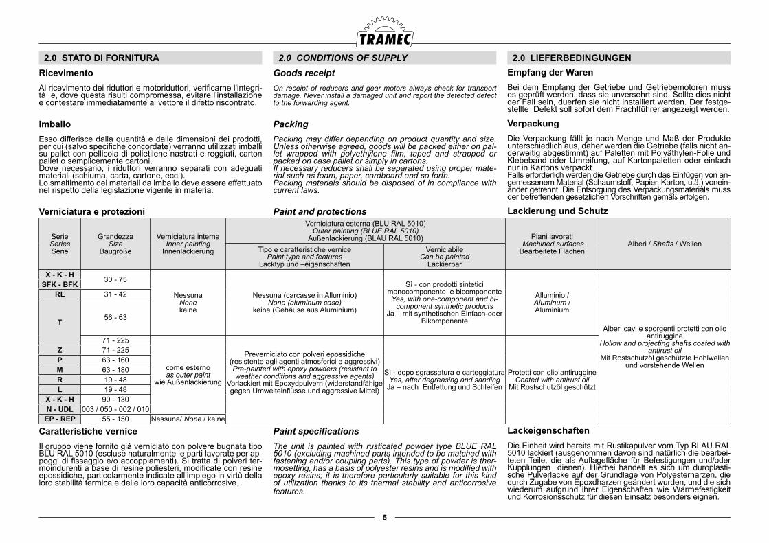
Paint and protections
Paint specifications The unit is painted with rusticated powder type BLUE RAL 5010 (excluding machined parts intended to be matched with fastening and/or coupling parts). This type of powder is ther-mosetting, has a basis of polyester resins and is modified with epoxy resins; it is therefore particularly suitable for this kind of utilization thanks to its thermal stability and anticorrosive features.
2.0 LIEFERBEDINGUNGENEmpfang der WarenBei dem Empfang der Getriebe und Getriebemotoren muss es geprüft werden, dass sie unversehrt sind. Sollte dies nicht der Fall sein, duerfen sie nicht installiert werden. Der festge-stellte Defekt soll sofort dem Frachtführer angezeigt werden.
VerpackungDie Verpackung fällt je nach Menge und Maß der Produkte unterschiedlich aus, daher werden die Getriebe (falls nicht an-derweitig abgestimmt) auf Paletten mit Polyäthylen-Folie und Klebeband oder Umreifung, auf Kartonpaletten oder einfach nur in Kartons verpackt.Falls erforderlich werden die Getriebe durch das Einfügen von an-gemessenem Material (Schaumstoff, Papier, Karton, u.ä.) vonein-ander getrennt. Die Entsorgung des Verpackungsmaterials muss der betreffenden gesetzlichen Vorschriften gemäß erfolgen.
Lackierung und Schutz
LackeigenschaftenDie Einheit wird bereits mit Rustikapulver vom Typ BLAU RAL 5010 lackiert (ausgenommen davon sind natürlich die bearbei-teten Teile, die als Auflagefläche für Befestigungen und/oder Kupplungen dienen). Hierbei handelt es sich um duroplasti-sche Pulverlacke auf der Grundlage von Polyesterharzen, die durch Zugabe von Epoxdharzen geändert wurden, und die sich wiederum aufgrund ihrer Eigenschaften wie Wärmefestigkeit und Korrosionsschutz für diesen Einsatz besonders eignen.
RicevimentoAl ricevimento dei riduttori e motoriduttori, verificarne l'integri-tà e, dove questa risulti compromessa, evitare l'installazione e contestare immediatamente al vettore il difetto riscontrato.
ImballoEsso differisce dalla quantità e dalle dimensioni dei prodotti, per cui (salvo specifiche concordate) verranno utilizzati imballi su pallet con pellicola di polietilene nastrati e reggiati, carton pallet o semplicemente cartoni.Dove necessario, i riduttori verranno separati con adeguati materiali (schiuma, carta, cartone, ecc.).Lo smaltimento dei materiali da imballo deve essere effettuato nel rispetto della legislazione vigente in materia.
Verniciatura e protezioni
Caratteristiche verniceIl gruppo viene fornito già verniciato con polvere bugnata tipo BLU RAL 5010 (escluse naturalmente le parti lavorate per ap-poggi di fissaggio e/o accoppiamenti). Si tratta di polveri ter-moindurenti a base di resine poliesteri, modificate con resine epossidiche, particolarmente indicate all’impiego in virtù della loro stabilità termica e delle loro capacità anticorrosive.
SerieSeriesSerie
GrandezzaSize
Baugröße
Verniciatura internaInner painting
Innenlackierung
Verniciatura esterna (BLU RAL 5010)Outer painting (BLUE RAL 5010)
Außenlackierung (BLAU RAL 5010) Piani lavorati Machined surfacesBearbeitete Flächen
Alberi / Shafts / WellenTipo e caratteristiche vernice
Paint type and featuresLacktyp und –eigenschaften
VerniciabileCan be painted
LackierbarX - K - H
30 - 75
NessunaNonekeine
Nessuna (carcasse in Alluminio)None (aluminum case)
keine (Gehäuse aus Aluminium)
Sì - con prodotti sintetici monocomponente e bicomponenteYes, with one-component and bi-
component synthetic productsJa – mit synthetischen Einfach-oder
Bikomponente
Alluminio / Aluminum / Aluminium
Alberi cavi e sporgenti protetti con olio antiruggine
Hollow and projecting shafts coated with antirust oil
Mit Rostschutzöl geschützte Hohlwellen und vorstehende Wellen
SFK - BFKRL 31 - 42
T 56 - 63
71 - 225
come esternoas outer paint
wie Außenlackierung
Preverniciato con polveri epossidiche(resistente agli agenti atmosferici e aggressivi)Pre-painted with epoxy powders (resistant to weather conditions and aggressive agents)
Vorlackiert mit Epoxydpulvern (widerstandfähige gegen Umwelteinflüsse und aggressive Mittel)
Sì - dopo sgrassatura e carteggiaturaYes, after degreasing and sanding
Ja – nach Entfettung und Schleifen
Protetti con olio antiruggineCoated with antirust oil
Mit Rostschutzöl geschützt
Z 71 - 225P 63 - 160M 63 - 180R 19 - 48L 19 - 48
X - K - H 90 - 130N - UDL 003 / 050 - 002 / 010
EP - REP 55 - 150 Nessuna/ None / keine
6
Result achieved after testing UNICHIM metal sheets
Hardness (pencil) H:
Corrosion strength:
Quick aging:
ASTM G 53 unchanged
Note:Use special corrosion-proof paints in case of particularly ag-gressive environment or for any other special needs. Protect the outer edge of oil seals so that seal rubber does not dry up and crack, thus causing oil leaks.
Rubber parts and breather plug holes, if present, should not be painted.
For outdoor applications apply water-repellent grease on the unit, especially on the rotary seats of the seal rings, in the area hollow shaft-machine pin, and on machine parts which are not used for fastening.
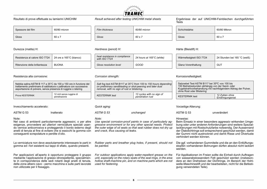
Risultato di prove effettuate su lamierini UNICHIM
Durezza (matita) H:
Resistenza alla corrosione:
Invecchiamento accelerato:
ASTM G 53 Inalterato
Note:Nel caso di ambienti particolarmente aggressivi, o per altre esigenze, provvedere ad ulteriori verniciature speciali usan-do vernice anticorrosiva e proteggendo il bordo esterno degli anelli di tenuta al fine di evitare che si essicchi la gomma con conseguenti screpolature e perdite d’olio.
La verniciatura non deve assolutamente interessare le parti in gomma ed i fori esistenti sui tappi di sfiato, quando presenti.
Per applicazioni all’aperto è opportuno proteggere il gruppo mediante l’applicazione di grasso idrorepellente, specialmen-te in corrispondenza delle sedi rotanti degli anelli di tenuta, della zona albero cavo - perno macchina e sulle parti lavorate non utilizzate per il fissaggio.
Ergebnisse der auf UNICHIM-Feinblechen durchgeführten Tests
Härte (Bleistift) H:
Korrosionsfestigkeit:
Vorzeitige Alterung:
ASTM G 53 unverändert
Hinweise:Beim Einsatz in einer besonders aggressiv wirkenden Umge-bung oder unter anderen Anforderungen sind weitere Spezial-lackierungen mit Rostschutzfarbe notwendig. Der Aussenrand der Ölabdichtringe soll entsprechend geschützt werden, damit der Gummi nicht austrocknet und damit Risse und Ölverluste verhindert werden können.
Die ggf. vorhandenen Gummiteile und die an den Entlüftungs-stopfen vorhandenen Bohrungen dürfen absolut nicht lackiert werden.
Für Applikationen im Freien sollte die Einheit durch Auftragen von wasserabstossendem Fett geschützt werden (insbeson-dere an den Drehsitzen der Dichtringe, im Bereich der Hohl-welle-Maschinestift und der bearbeiteten, nicht für die Befesti-gung verwendeten Teile).
Spessore del film 60/80 micron
Gloss 60 ± 7
Film thickness 60/80 micron
Gloss 60 ± 7
Schichtstärke 60/80 Mikron
Gloss 60 ± 7
Resistenza al calore ISO 7724 24 ore a 165°C (bianco)
Ritenzione della brillantezza BUONA
heat resistance in compliance with ISO 7724 24 hours at 165°C (white)
Gloss resolution level GOOD
Wärmefestgkeit ISO 7724 24 Stunden bei 165 °C (weiß)
Glanz-Vorenthaltung GUT
Nebbia salina ASTM B 117 a 35°C da 100 a 150 ore in funzione del trattamento preliminare di sabbiatura o pallinatura con successiva asportazione di polvere, senza presenza di ruggine o istering
Prova KESTERNIK 12 cicli senza ruggine di penetrazione
Salt fog test ASTM B117 at 35°C from 100 to 150 hours depending on preliminary sandblasting or shot-peening and later dust removal, with no sign of rust or blistering.
KESTERNIK test 12 cycles with no sign of penetration rust
Salznebel Test ASTM B117 bei 35ºC von 100 bis 150 Betriebsstunden abhängig von der Sand- oder Kugelstrahlvorbehandlung mit nachfolgendem Abtrag der Pulver, ohne Rost oder Blistering
KESTERNIK test 12 Zyklen ohne Eindringungsrost
7
IdentifikationAlle Getriebe und Getriebemotoren werden durch ein Typen-schild gekennzeichnet, auf dem die Bau-und Betriebseigen-schaften angegeben werden (dadurch werden sowohl die vo-rausgehenden vertraglich festgelegten Baueigenschaften als auch die Betriebseigenschaften festgelegt).Das Typenschild darf nicht abgenommen oder beschädigt werden, weil die darauf angegebenen Daten im Fall einer Er-satzteilanforderung und im Hinblick auf eine eventuelle Aner-kennung der Garantie angegebenen werden sollen.
Bewegung und EinlagerungFür das Heben der Einheit sollten angemessene Vorrichtun-gen (Häken, Riemen, Ketten, Transportösen, usw.) verwendet werden, die für das zu hebende Gewicht bemessen sind und die der Sicherheitsvorschriften entsprechen. Ebenso muss es überprüft werden, ob die Gewichtsverteilung der Last ausge-glichen ist.Die Ankoppelungspunkte sind mit den Bohrungen auf dem Gahäuse identifizierbar, denen zur Befestigung dienen. Die Ankoppelungspunkte dienen zu dem Heben des Getriebes als einzelne Einheit.Die Benutzung der am Kopf der vorstehenden Welle liegen-den Gewindebohrung und der Tragöse des Motors ist jedoch zu vermeiden.
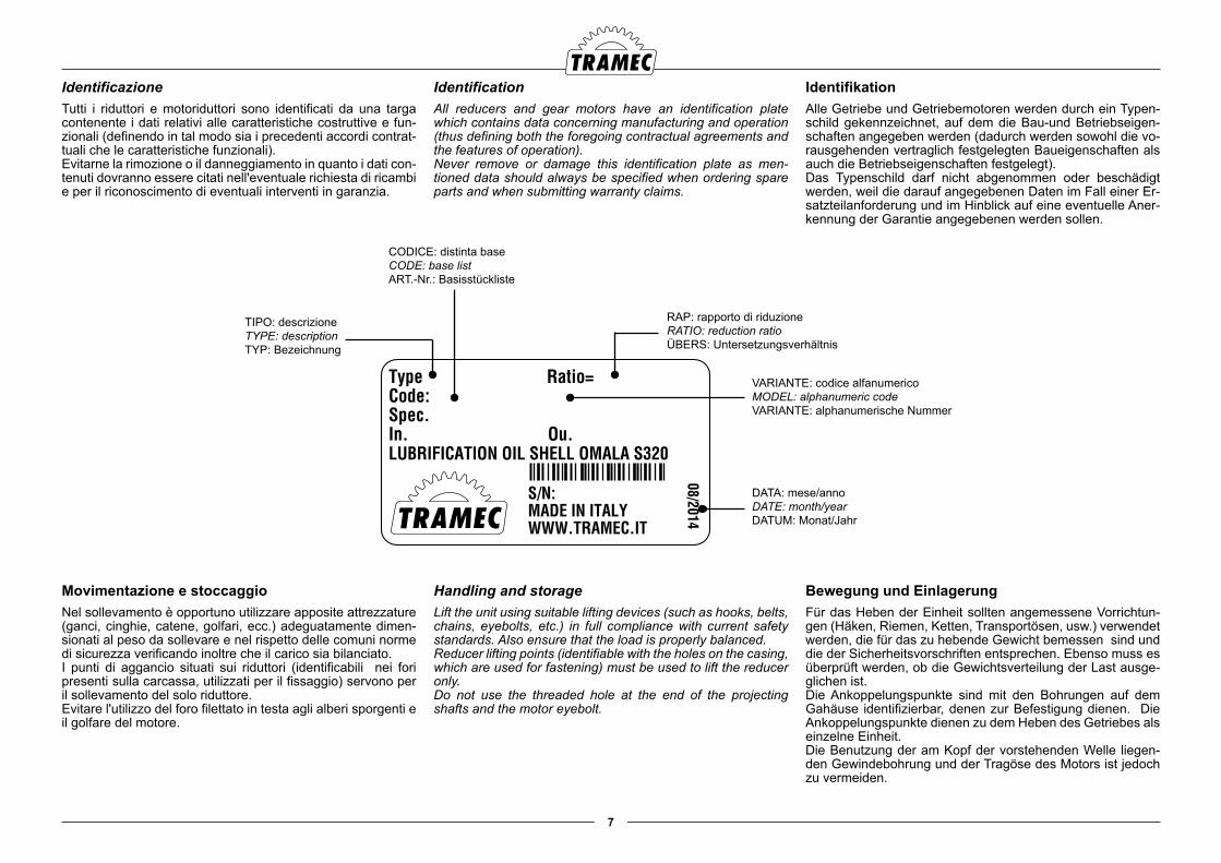
IdentificationAll reducers and gear motors have an identification plate which contains data concerning manufacturing and operation (thus defining both the foregoing contractual agreements and the features of operation).Never remove or damage this identification plate as men-tioned data should always be specified when ordering spare parts and when submitting warranty claims.
Handling and storageLift the unit using suitable lifting devices (such as hooks, belts, chains, eyebolts, etc.) in full compliance with current safety standards. Also ensure that the load is properly balanced.Reducer lifting points (identifiable with the holes on the casing, which are used for fastening) must be used to lift the reducer only. Do not use the threaded hole at the end of the projecting shafts and the motor eyebolt.
IdentificazioneTutti i riduttori e motoriduttori sono identificati da una targa contenente i dati relativi alle caratteristiche costruttive e fun-zionali (definendo in tal modo sia i precedenti accordi contrat-tuali che le caratteristiche funzionali).Evitarne la rimozione o il danneggiamento in quanto i dati con-tenuti dovranno essere citati nell'eventuale richiesta di ricambi e per il riconoscimento di eventuali interventi in garanzia.
Movimentazione e stoccaggioNel sollevamento è opportuno utilizzare apposite attrezzature (ganci, cinghie, catene, golfari, ecc.) adeguatamente dimen-sionati al peso da sollevare e nel rispetto delle comuni norme di sicurezza verificando inoltre che il carico sia bilanciato.I punti di aggancio situati sui riduttori (identificabili nei fori presenti sulla carcassa, utilizzati per il fissaggio) servono per il sollevamento del solo riduttore.Evitare l'utilizzo del foro filettato in testa agli alberi sporgenti e il golfare del motore.
Type Ratio=Code: Spec. In. Ou. LUBRIFICATION OIL SHELL OMALA S320
S/N: MADE IN ITALY WWW.TRAMEC.IT
08/2014
TIPO: descrizioneTYPE: descriptionTYP: Bezeichnung
RAP: rapporto di riduzioneRATIO: reduction ratioÜBERS: Untersetzungsverhältnis
DATA: mese/annoDATE: month/yearDATUM: Monat/Jahr
VARIANTE: codice alfanumericoMODEL: alphanumeric codeVARIANTE: alphanumerische Nummer
CODICE: distinta baseCODE: base listART.-Nr.: Basisstückliste
8
Die korrekte Einlagerung der Produkte erfordert folgende Maßnahmen:
● Keine Einlagerung im Freien oder in Plätze, die von Witterungseinflüssen oder starker Feuchtigkeit betroffen sind
● Zwischen Boden und Produkten immer Flachböden aus Holz oder anderem Material einfügen, so dass ein direkter Kontakt mit dem Boden vermieden wird.
● Vermeiden, dass die Getriebe übereinander gestapelt werden.
Die bereits mit Schmieröl gelieferten Getriebe müssen in der gleichen Position gelagert werden, in der sie später montiert werden sollen.Die bearbeiteten jedoch nicht lackierten Flächen, die Wellen und die Dichtungen sollen mit Rostschutzöl oder Fett ge-schützt werden. Regelmäßig soll deren Zustand kontrolliert werden. Die Abtriebswelle muss in Zeitabständen von 4-5 Mo-naten gedreht werden.Die normale Lagerungszeit sieht Temperaturen zwischen -20°C und +40 °C in einem überdachten, sauberen, trockenen und vibrationsfreiem Platz vor und beläuft sich auf die Dauer 1 Jahres, wenn während des Transports die angemessenen Schutzvorrichtungen gesichert wurden.Die Lagerungszeit kann dank Ergreifung folgender Maßnah-men bis auf 2 Jahre hinausgezogen werden.Die bearbeiteten, jedoch nicht lackierten Flächen, die Wellen und die Dichtungen müssen mit Rostschutzöl oder –fett ge-schützt werden. Den entsprechenden Erhaltungszustand re-gelmäßig kontrollieren.Die ohne Öl gelieferten Getriebe vollständig mit Öl füllen. Be-vor die Maschine in Betrieb genommen wird, ist der richtige Ölstand wiederherzustellen.In Zeitabständen von 4-5 Monaten muss die Abtriebswelle ge-dreht werden.Für Einlagerung über 2 Jahre oder in Plätze, die nicht mit den o.g. übereinstimmen, muss ein Techniker der Tramec konsul-tiert werden.
To properly store reducers and gear motors, proceed as fol-lows:
● do not store outdoors, in areas subject to weather conditions or in highly humid environments.
● never store the goods directly onto the floor but place them onto wooden pallets or any other suitable surface in order to avoid direct contact with the ground
● reducers should never be stacked.
Reducers which are filled with oil should be stored in the same mounting position they are going to be installed in.
Apply antirust oil or grease onto unpainted machine surfaces, shafts and seals. Check that they are in good condition at reg-ular intervals. Rotate the output shaft every 4-5 months.
Provided that reducers and gear motors are stored indoors in a dry, clean and vibration-free place at a temperature ranging between -20° and +40°C, and provided that they had been duly protected during transport, they can be stored for one year.
Proceed as follow to extend storage time to two years:
Apply antirust oil or grease onto unpainted machine surfaces, shafts and seals and check that they are in good condition at regular intervals.Fully fill with oil the reducers wich were delivered empty. Be-fore installing the reducer, the oil must be returned to the op-erating level.
Rotate the output shaft every 4-5 months.
Please contact Tramec Technical Service Department for stor-age over two years or storage in environments other than the specified ones.
Il corretto stoccaggio dei prodotti ricevuti richiede l’esecuzione delle seguenti attività:
● Escludere aree all’aperto, zone esposte alle intemperie o con eccessiva umidità.
● Interporre sempre tra il pavimento ed i prodotti, pianali in legno o di altra natura per impedire il diretto contatto col suolo.
● Evitare l'accatastamento dei riduttori.
I riduttori forniti completi di olio lubrificante devono essere im-magazzinati nella stessa posizione di montaggio in cui verran-no installati.Proteggere le superfici lavorate non verniciate, gli alberi e le tenute con olio antiruggine o grasso controllandone periodi-camente lo stato di conservazione. Ad intervalli di 4-5 mesi effettuare una rotazione dell'albero lento.Il normale periodo di stoccaggio, previsto a temperature com-prese fra -20°C e +40°C in ambiente coperto asciutto, pulito, secco e in assenza di vibrazioni, è di 1 anno a condizione che siano state assicurate adeguate protezioni durante il traspor-to.
Tale periodo può essere protratto fino a 2 anni adottando i seguenti accorgimenti:Proteggere le superfici lavorate non verniciate, gli alberi e le tenute con olio antiruggine o grasso controllandone periodica-mente lo stato di conservazione.Riempire totalmente con olio i riduttori forniti senza, avendo cura di ripristinare il livello corretto in fase di installazione.
Ad intervalli di 4-5 mesi effettuare una rotazione dell'albero lento.Per periodi di stoccaggio superiori a 2 anni o in ambienti diver-si da quelli sopra citati consultare il Servizio ecnico Tramec.
3.0 INSTALLAZIONE 3.0 INSTALLATION
Please follow the instructions below.Remove all protections in the packing.
Position the reducer in the correct mounting position which was specified in the order and check the oil level through the oil window (if available).
3.0 INSTALLATION
Die folgenden Anleitungen sind zu befolgen.Die eventuell in der Verpackung vorhandenen Schutzvorrich-tungen abnehmen.Das Getriebe in die auftragsgemäß korrekte Einbaulage brin-gen, dabei durch die Ölstandskontrolle (wo vorgesehen) den Ölstand überprüfen.
Attenersi alle seguenti indicazioni.Togliere eventuali protezioni presenti nell'imballo.
Orientare il riduttore nella corretta posizione di montaggio richiesta in fase di ordine verificando tramite l'apposita spia (dove previsto) il livello del lubrificante immesso.
9
Die Montage der Getriebe in einer Einbaulage, der von der in der Bestellung angegeben Position abweicht, kann zu einer schnellen Beschädigung der inneren Bestandteile führen.
Im Fall der bereits mit Öl gefüllten und mit Ölschraube ausge-statteten Getriebe muss die obere, geschlossene Verschluss-schraube durch den mitgelieferten Entlüftungsschraube er-setzt werden.
Bei Getriebemotoren, die nahe an Verkleidungsteilen ange-ordnet sind, muss es überprüft werden, dass auf der Seite des Motorlüfterrads ein ausreichender Luftfluss für die korrek-te Kühlung der Einheit gewährleistet ist.
Die Getriebe sowie die Getriebemotoren müssen vor Witte-rungseinflüssen und direkter Sonneneinstrahlung geschützt werden, dabei muss für die Belüftung und die Inspektion ein angemessener Freiraum gewährleistet werden.Überprüfen, dass die Drehrichtung der in der Bestellung ange-forderten Richtung entspricht.Die Befestigungsflächen sorgfältig reinigen (dabei ggf. Lack-reste entfernen) und die perfekte Ebenheit und Festigkeit überprüfen.
Sich darüber vergewissern, dass die Befestigung stabil ist, um das Entstehen von Schwingungen zu verhindern , die zu ho-hen Geräuschpegeln, zu dem Lockern der Schrauben und zu möglichen Ermüdungsbrüchen führen könnten.
An den Befestigungsschrauben von Getriebe-Maschine und Getriebe-Flansch wird es empfohlen, einen mittelstarken Kleb-stoff zu verwenden. Damit wird das Eintreten von Lockerungen verhindert, jedoch wird ein späterer Ausbau noch ermöglicht.
Falls die Applikation Überlasten von langer Dauer vorsieht, müssen entsprechende Vorrichtungen zur Begrenzung des Drehmoments, Kupplungen, usw. verwendet werden.Eine korrekte Fluchtung zwischen Getriebe und Motor und/oder eventuellen Verbindungsteilen soll gewährleistet wer-den. Womöglich duerfen elastische Verbindungskupplungen verwenden werden.
Wird der Motor direkt am Getriebeflansch montiert, muss man sich darüber vergewissern, dass dadurch kein Hebeleffekt er-zeugt wird und dass die beiden Flanschen komplanar sind.
Falls eventuelle Schmiermittelverluste die Verschmutzung des Produkts oder andere Schäden verursachen könnten, müs-sen häufig Inspektionen vorgenommen werden; ggf. duerfen zusätzliche Verkleidungsteile vorgesehen oder Schmiermittel für Einsatz in der Lebensmittelindustrie verwendet werden
If reducers are installed in a position other than the mounting position specified in the order, this may cause damage to its inner parts.
Replace the upper plug with the supplied breather plug in re-ducers which are delivered filled with oil and equipped with oil plugs.
Ensure that gear motors, which are close to housings, have enough space on the motor fan side to enable them to cool down.
Reducers and gear motors should be protected against bad weather or direct sun light and should also have enough space around them in order to allow proper ventilation and inspection.Ensure that direction of rotation is as ordered.Carefully clean all fastening surfaces, remove all paint resi-dues and check for perfect flatness and stiffness.
Ensure that the reducer is firmly fastened in order to prevent vibrations which might cause noise, screw loosening and pos-sible fatigue failure.
Apply medium-strength adhesives onto the screws fasten-ing the reducer to the machine and the flange to prevent any slackening yet to allow subsequent necessary disassembly.
If the application requires long-lasting overloads, torque limit-ers, clutches and so forth should be installed.
Reducer, motor and/or all connecting parts should be duly aligned. If possible, it is advisable to use flexible joints.
If the motor is directly installed onto the reducer flange, ensure that no lever force is applied and that both flanges are in the same plane.
Perform frequent checks in case of applications in which oil leaks may contaminate the product or cause other damage. If necessary fit additional housings or use lubricants for the food industry .
Il montaggio di riduttori in posizioni diverse da quelle specificate in fase di ordine può portare ad un rapido dan-neggiamento degli organi interni.
Nei riduttori forniti completi di olio e provvisti di tappi olio so-stituire il tappo chiuso superiore con quello di sfiato fornito in dotazione.
Per i motoriduttori che si trovano in prossimità di carterature, verificare che sia garantito dal lato ventola del motore un flus-so d'aria sufficiente per il corretto raffreddamento del gruppo.
I riduttori e i motoriduttori devono essere protetti dalle intem-perie e dall'irraggiamento diretto del sole garantendo però adeguati spazi per l'aerazione e per l'ispezione.Verificare che il senso di rotazione sia quello richiesto in fase di ordine.Pulire accuratamente le superfici di fissaggio (asportando, se necessario, eventuali tracce di vernice) e verificarne la perfet-ta planarità e rigidezza.
Assicurarsi che il fissaggio sia stabile al fine di evitare l'insor-gere di vibrazioni che potrebbero causare rumorosità, allenta-mento delle viti e il verificarsi di possibili rotture a fatica.
Nelle viti di fissaggio riduttore-macchina e riduttore flangia, si consiglia l'utilizzo di adesivi bloccanti di media resistenza per evitare la possibilità di allentamenti e consentire comunque successivi smontaggi.
Se nell'applicazione sono previsti sovraccarichi di lunga du-rata, occorre prevedere dispositivi di limitazione della coppia, frizioni, ecc. È opportuno garantire il corretto allineamento fra il riduttore e il motore e/o eventuali organi di collegamento; dove possibile, è preferibile utilizzare giunti elastici.
Se il motore è montato direttamente sulla flangia del riduttore, assicurarsi che non venga generato un effetto leva e che le due flange risultino complanari.
In applicazioni dove eventuali perdite di lubrificante possono causare inquinamento del prodotto o altri danni, effettuare del-le frequenti ispezioni, ed eventualmente prevedere carterature supplementari o utilizzare lubrificanti per industria alimentare.
10
In mit Schadstoff belasteten Plätze müssen angemessene Maßnahmen getroffen werden, um die Verschmutzung des Schmiermittels zu vermeiden.Sind bei der Applikation häufige Anlauf- und Stoppschaltun-gen vorgesehen, wird es empfohlen, den Motor mit eingebau-ten Thermofühler anzufordern.
Installation der Getriebe mit Abntriebshohlwelle
Für alle Getriebe mit Hohlwelle (mit Keilnut) muss die korrekte Montage den nachstehenden Angaben gemäß erfolgen:Für die Montage und den Ausbau von Getrieben mit Feder-ringnut die Angaben in Abb. 1_01 und Abb. 1_03 befolgen.Für die axiale Befestigung der mit Keilnut versehenen Getrie-be kann das in Abb. 1_02 dargestellten Verfahren angewen-det werden.
In polluting environments take all necessary steps to avoid lubricant contamination.
If the application requires frequent starts and stops, a motor with built-in thermal feeler is recommended.
Installing reducers with hollow output shaft
All reducers featuring hollow shafts (i.e. key way), should be installed as described below.Install and remove reducers with spring ring groove as shown in figures 1_01 and 1_03.Axial fastening of the reducers with key way occurs as shown in fig. 1_02.
In ambienti inquinanti adottare gli opportuni accorgimenti per evitare la contaminazione del lubrificante.
Se l'applicazione prevede frequenti avviamenti e arresti, è consigliabile richiedere il motore con sonde termiche incor-porate.
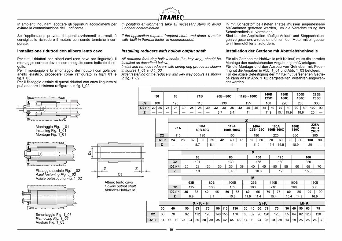
Installazione riduttori con allbero lento cavo
Per tutti i riduttori con alberi cavi (con cava per linguetta), il montaggio corretto deve essere eseguito come indicato di se-guito.Per il montaggio e lo smontaggio dei riduttori con gola per anello elastico, procedere come raffigurato in fig.1_01 e fig.1_03.Per il fissaggio assiale di questi riduttori con cava linguetta si può adottare il sistema raffigurato in fig.1_02.
T56 63 71B 90B - 80C 112B - 100C 140B
125C180B160C
200B180C
225B200C
C2 100 120 115 130 155 180 220 260 300D2 H7 20 25 25 28 30 24 28 30 32 30 35 42 40 45 55 50 70 60 90 80 100 90
Z — — — — — — — — 8.7 8.4 11 11.9 15.4 15.9 18.9 20 —
Z
71A 90A80B-80C
112A100B-100C
140A125B-125C
180A160B-160C
180B180C
225A200B200C
C2 115 130 155 180 220 260 300D2 H7 24 28 32 30 35 42 40 45 55 50 70 60 90 80 100 90
Z — — 8.7 8.4 11 11.9 15.4 15.9 18.9 20 —
P63 80 100 125 160
C2 101 130 155 180 220D2 H7 25 28 30 30 35 38 40 45 50 55 60 65 70
Z 7.3 8.5 10.8 12 15.5
M63B 80B 100B 125B 140B 160B 180B
C2 115 130 155 180 210 260 300D2 H7 35 38 40 45 50 55 60 65 70 75 80 85 90 100
Z 6.9 8.1 10.3 11.9 11.4 15.4 15.4 14.9 16.9
X - K - H SFK BFK30 40 50 63 75 90 110 130 30 40 50 63 75 30 40 50 63 75
C2 63 78 92 112 120 140 155 170 63 82 98 120 120 55 64 82 120 120
D2 H8 14 18 19 25 24 25 28 30 35 42 45 48 14 19 24 25 28 30 14 18 25 25 28 30
Albero lento cavoHollow output shaftAbtriebs-Hohlwelle
Montaggio Fig. 1_01Installing Fig. 1_01Montage Fig. 1_01
Fissaggio assiale Fig. 1_02Axial fastening Fig. 1_02Axiale befestigung Fig. 1_02
Smontaggio Fig. 1_03Removing Fig. 1_03Ausbau Fig. 1_03
11
Installation– Getriebe mit Hohlwelle und Schrumpfscheibe
Wie folgt verfahren:Nach dem stückweisen und aufeinanderfolgenden Lösen der Fest-stellschrauben die Schrumpfscheibe von der Welle entfernen.
Die Kupplungsflächen zwischen der Abtriebswelle des Getrie-bes und der Maschinenwelle säubern und entfetten.
Die Schrumpfscheibe erneut auf die Getriebeabtriebswel-le montieren, dann, nach der Kupplung der beiden Wellen (Hohlwelle des Getriebes und der Maschine) die Schrauben schrittweise und hintereinander mit einem Drehmoment-schlüssel anziehen, dem auf das in der nachstehenden Ta-belle angegebene Anzugsmoment eingestellt ist.
Installation – Aufsteckgetriebe
Die Ausfsteckgetriebe werden direkt an die Maschinenwel-le montiert und müssen mit der Maschine über einen Bügel (Drehmomentstütze oder Spannvorrichtung) verbunden wer-den, welchen der Drehung der Getriebe entgegenwirkt. Das Getriebe muss sowohl radial als auch axial befestigt werden.Die in der Drehmomentstütze vorhandene Bohrung muss eine Bindung aufweisen, die axial frei ist und die ein ausreichendes Spiel hat, sodass geringe Schwingungen der Getriebe wäh-rend des Betriebs möglich sind. Die mangelnde Einhaltung dieser Bedingungen kann zu Lasten auf die Lager und folglich auf deren Beschädigung führen.Eventuell durch das Ablösen des Getriebes oder seine Um-drehung verursachten Gefahren können durch das Anbringen entsprechender Sicherheitsvorrichtungen vermieden werden.
Installing reducers with hollow shaft and shrink disk
Proceed as follows:Undo the fastening screws gradually one after the other and remove the shrink disk from the shaft.
Carefully clean and degrease the coupling surfaces between reducer output shaft and machine shaft.
Install the shrink disk onto the reducer output shaft and after having completed the coupling between the two shafts (reduc-er hollow shaft and machine shaft), tighten the screws gradu-ally one after the other using a dynamometric wrench set to the tightening torque as specified in the following table.
Installing shaft-mounted reducers
Shaft-mounted reducers should be installed directly onto the machine shaft through a bracket (either a torque arm or a ten-sioner) which will counteract its rotation. The reducer should be fastened both radially and axially.
The hole on the torque arm should have a constraint which is axially free and also have enough play to allow the reducer to swing lightly whilst in operation.
Failure to follow the above instructions may lead to loads on the bearings and subsequential damage.Suitable safety measures should be taken to avoid any risks resulting from reducer detachment or its rotation.
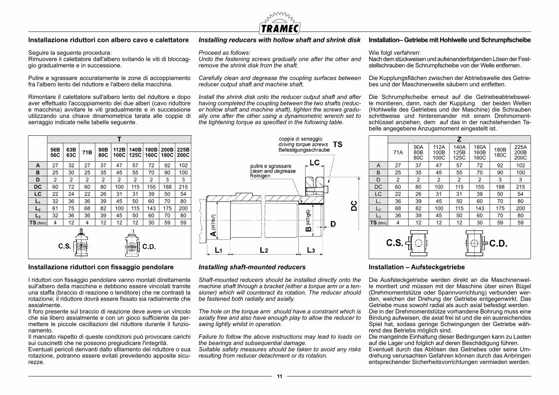
Installazione riduttori con albero cavo e calettatore
Seguire la seguente procedura:Rimuovere il calettatore dall'albero svitando le viti di bloccag-gio gradualmente e in successione.
Pulire e sgrassare accuratamente le zone di accoppiamento fra l'albero lento del riduttore e l'albero della macchina.
Rimontare il calettatore sull'albero lento del riduttore e dopo aver effettuato l'accoppiamento dei due alberi (cavo riduttore e macchina) avvitare le viti gradualmente e in successione utilizzando una chiave dinamometrica tarata alle coppie di serraggio indicate nelle tabelle seguente.
Installazione riduttori con fissaggio pendolare
I riduttori con fissaggio pendolare vanno montati direttamente sull'albero della macchina e debbono essere vincolati tramite una staffa (braccio di reazione o tenditore) che ne contrasti la rotazione; il riduttore dovrà essere fissato sia radialmente che assialmente.Il foro presente sul braccio di reazione deve avere un vincolo che sia libero assialmente e con un gioco sufficiente da per-mettere le piccole oscillazioni del riduttore durante il funzio-namento. Il mancato rispetto di queste condizioni può provocare carichi sui cuscinetti che ne possono pregiudicare l'integrità.Eventuali pericoli derivanti dallo sfilamento del riduttore o sua rotazione, potranno essere evitati prevedendo apposite sicu-rezze.
Z
71A90A80B80C
112A100B100C
140A125B125C
180A160B160C
180B180C
225A200B200C
A 27 37 47 57 72 92 102B 25 35 45 55 70 90 100D 2 2 2 2 2 3 3
DC 60 80 100 115 155 188 215LC 22 26 31 31 39 50 54L1 36 39 45 50 60 70 80L2 68 82 100 115 143 175 200L3 36 39 45 50 60 70 80
TS (Nm) 4 12 12 12 30 59 59
T56B56C
63B63C 71B 90B
80C112B100C
140B125C
180B160C
200B180C
225B200C
A 27 32 27 37 47 57 72 92 102B 25 30 25 35 45 55 70 90 100D 2 2 2 2 2 2 2 3 3
DC 60 72 60 80 100 115 155 188 215LC 22 24 22 26 31 31 39 50 54L1 32 36 36 39 45 50 60 70 80L2 61 75 68 82 100 115 143 175 200L3 32 36 36 39 45 50 60 70 80
TS (Nm) 4 12 4 12 12 12 30 59 59
12
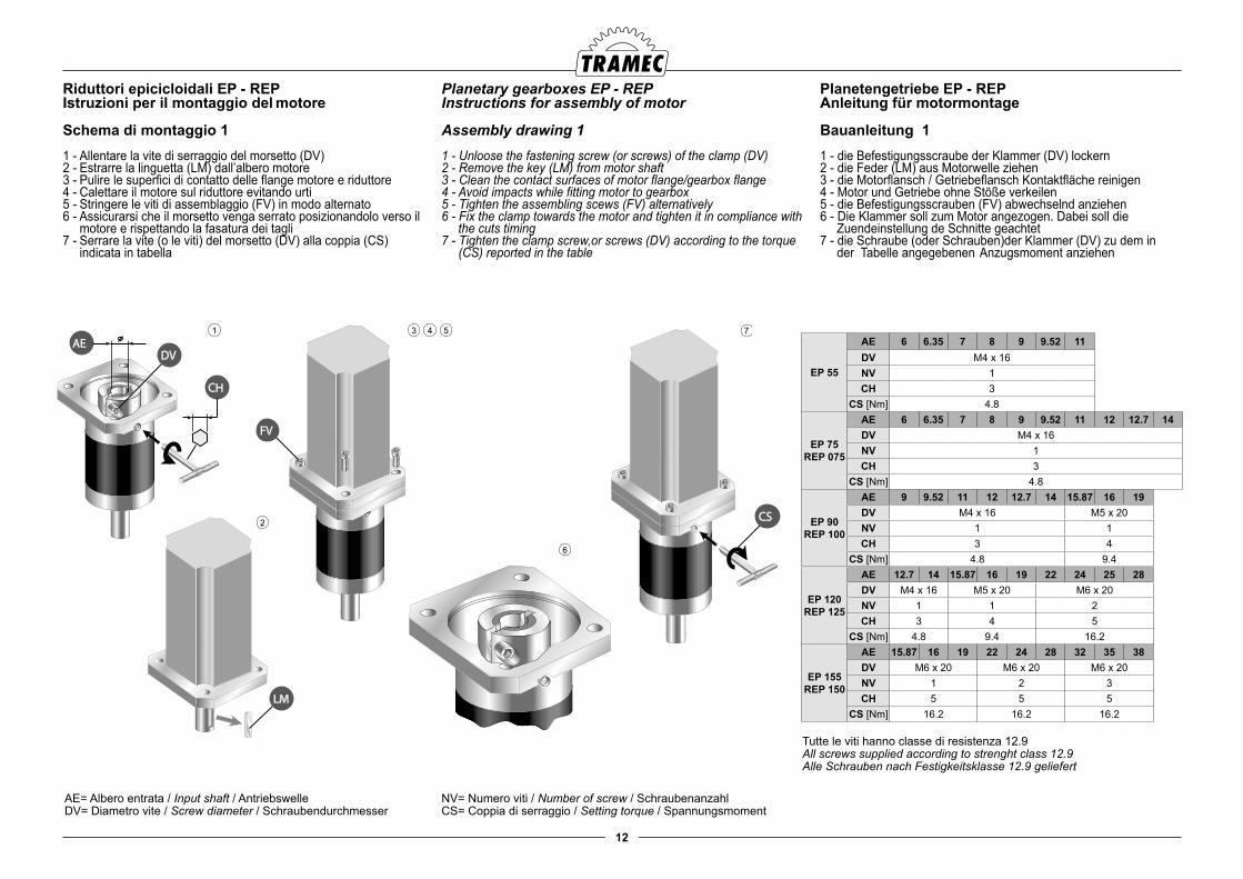
Riduttori epicicloidali EP - REPIstruzioni per il montaggio del motore
Schema di montaggio 11 - Allentare la vite di serraggio del morsetto (DV)2 - Estrarre la linguetta (LM) dall’albero motore 3 - Pulire le superfici di contatto delle flange motore e riduttore4 - Calettare il motore sul riduttore evitando urti5 - Stringere le viti di assemblaggio (FV) in modo alternato6 - Assicurarsi che il morsetto venga serrato posizionandolo verso il
motore e rispettando la fasatura dei tagli7 - Serrare la vite (o le viti) del morsetto (DV) alla coppia (CS)
indicata in tabella
Planetary gearboxes EP - REPInstructions for assembly of motor
Assembly drawing 11 - Unloose the fastening screw (or screws) of the clamp (DV)2 - Remove the key (LM) from motor shaft3 - Clean the contact surfaces of motor flange/gearbox flange4 - Avoid impacts while fitting motor to gearbox5 - Tighten the assembling scews (FV) alternatively6 - Fix the clamp towards the motor and tighten it in compliance with
the cuts timing7 - Tighten the clamp screw,or screws (DV) according to the torque
(CS) reported in the table
Planetengetriebe EP - REPAnleitung für motormontage
Bauanleitung 11 - die Befestigungsscraube der Klammer (DV) lockern2 - die Feder (LM) aus Motorwelle ziehen3 - die Motorflansch / Getriebeflansch Kontaktfläche reinigen4 - Motor und Getriebe ohne Stöße verkeilen5 - die Befestigungsscrauben (FV) abwechselnd anziehen6 - Die Klammer soll zum Motor angezogen. Dabei soll die
Zuendeinstellung de Schnitte geachtet7 - die Schraube (oder Schrauben)der Klammer (DV) zu dem in der Tabelle angegebenen Anzugsmoment anziehen
FV
CS
LM
DVAE
CH
3 4 51
2
6
7
EP 55
AE 6 6.35 7 8 9 9.52 11DV M4 x 16NV 1CH 3
CS [Nm] 4.8
EP 75REP 075
AE 6 6.35 7 8 9 9.52 11 12 12.7 14DV M4 x 16NV 1CH 3
CS [Nm] 4.8
EP 90REP 100
AE 9 9.52 11 12 12.7 14 15.87 16 19DV M4 x 16 M5 x 20NV 1 1CH 3 4
CS [Nm] 4.8 9.4
EP 120REP 125
AE 12.7 14 15.87 16 19 22 24 25 28DV M4 x 16 M5 x 20 M6 x 20NV 1 1 2CH 3 4 5
CS [Nm] 4.8 9.4 16.2
EP 155REP 150
AE 15.87 16 19 22 24 28 32 35 38DV M6 x 20 M6 x 20 M6 x 20NV 1 2 3CH 5 5 5
CS [Nm] 16.2 16.2 16.2
Tutte le viti hanno classe di resistenza 12.9All screws supplied according to strenght class 12.9Alle Schrauben nach Festigkeitsklasse 12.9 geliefert
AE= Albero entrata / Input shaft / AntriebswelleDV= Diametro vite / Screw diameter / Schraubendurchmesser
NV= Numero viti / Number of screw / SchraubenanzahlCS= Coppia di serraggio / Setting torque / Spannungsmoment
13
EP 55
AE 6 6.35 7 8 9 9.52 11DV M4 x 16NV 1CH 3
CS [Nm] 4.8
EP 75REP 075
AE 6 6.35 7 8 9 9.52 11 12 12.7 14DV M4 x 16NV 1CH 3
CS [Nm] 4.8
EP 90REP 100
AE 9 9.52 11 12 12.7 14 15.87 16 19DV M4 x 16 M5 x 20NV 1 1CH 3 4
CS [Nm] 4.8 9.4
EP 120REP 125
AE 12.7 14 15.87 16 19 22 24 25 28DV M4 x 16 M5 x 20 M6 x 20NV 1 1 2CH 3 4 5
CS [Nm] 4.8 9.4 16.2
EP 155REP 150
AE 15.87 16 19 22 24 28 32 35 38DV M6 x 20 M6 x 20 M6 x 20NV 1 2 3CH 5 5 5
CS [Nm] 16.2 16.2 16.2
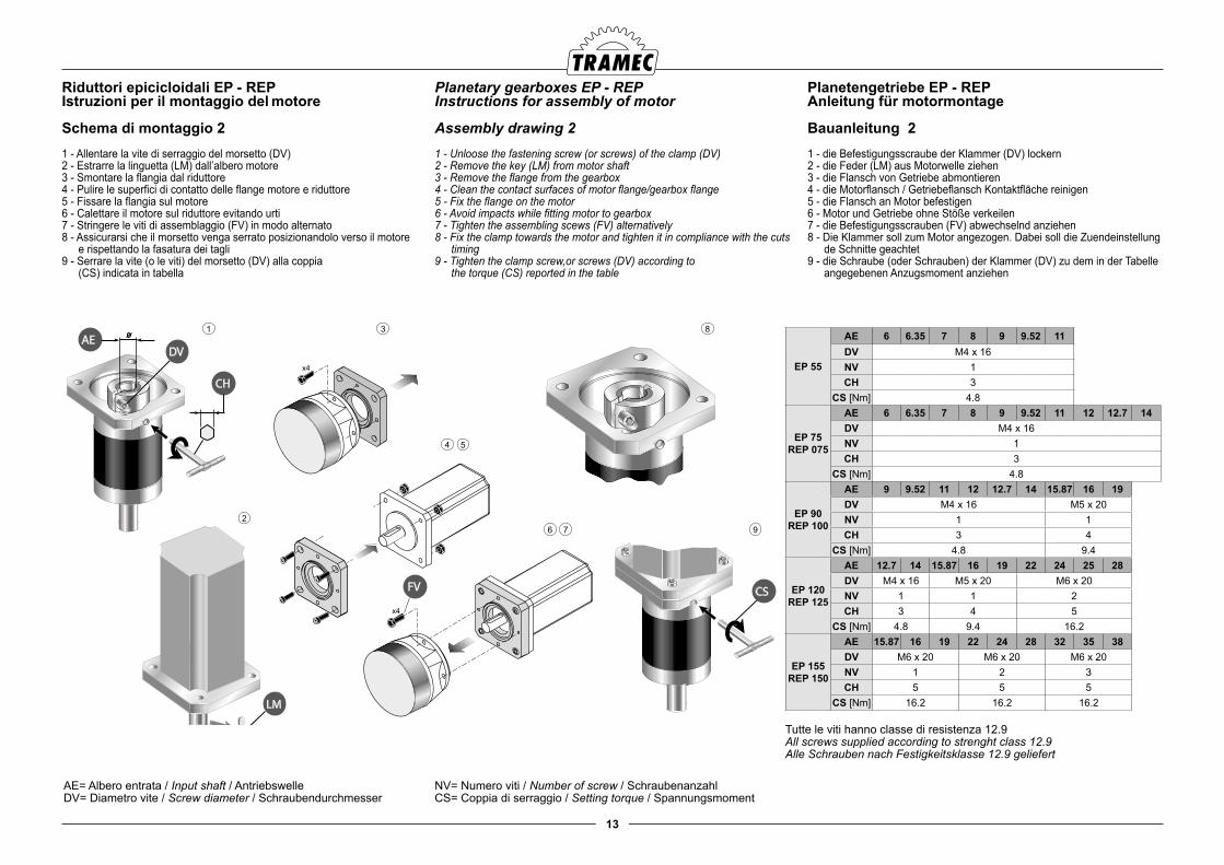
Riduttori epicicloidali EP - REPIstruzioni per il montaggio del motore
Schema di montaggio 21 - Allentare la vite di serraggio del morsetto (DV)2 - Estrarre la linguetta (LM) dall’albero motore 3 - Smontare la flangia dal riduttore4 - Pulire le superfici di contatto delle flange motore e riduttore5 - Fissare la flangia sul motore6 - Calettare il motore sul riduttore evitando urti7 - Stringere le viti di assemblaggio (FV) in modo alternato8 - Assicurarsi che il morsetto venga serrato posizionandolo verso il motore
e rispettando la fasatura dei tagli9 - Serrare la vite (o le viti) del morsetto (DV) alla coppia (CS) indicata in tabella
Planetary gearboxes EP - REPInstructions for assembly of motor
Assembly drawing 21 - Unloose the fastening screw (or screws) of the clamp (DV)2 - Remove the key (LM) from motor shaft3 - Remove the flange from the gearbox4 - Clean the contact surfaces of motor flange/gearbox flange5 - Fix the flange on the motor6 - Avoid impacts while fitting motor to gearbox7 - Tighten the assembling scews (FV) alternatively8 - Fix the clamp towards the motor and tighten it in compliance with the cuts
timing 9 - Tighten the clamp screw,or screws (DV) according to the torque (CS) reported in the table
Planetengetriebe EP - REPAnleitung für motormontage
Bauanleitung 21 - die Befestigungsscraube der Klammer (DV) lockern2 - die Feder (LM) aus Motorwelle ziehen3 - die Flansch von Getriebe abmontieren4 - die Motorflansch / Getriebeflansch Kontaktfläche reinigen5 - die Flansch an Motor befestigen6 - Motor und Getriebe ohne Stöße verkeilen7 - die Befestigungsscrauben (FV) abwechselnd anziehen8 - Die Klammer soll zum Motor angezogen. Dabei soll die Zuendeinstellung
de Schnitte geachtet 9 - die Schraube (oder Schrauben) der Klammer (DV) zu dem in der Tabelle
angegebenen Anzugsmoment anziehen
EP 55
AE 6 6.35 7 8 9 9.52 11DV M4 x 16NV 1CH 3
CS [Nm] 4.8
EP 75REP 075
AE 6 6.35 7 8 9 9.52 11 12 12.7 14DV M4 x 16NV 1CH 3
CS [Nm] 4.8
EP 90REP 100
AE 9 9.52 11 12 12.7 14 15.87 16 19DV M4 x 16 M5 x 20NV 1 1CH 3 4
CS [Nm] 4.8 9.4
EP 120REP 125
AE 12.7 14 15.87 16 19 22 24 25 28DV M4 x 16 M5 x 20 M6 x 20NV 1 1 2CH 3 4 5
CS [Nm] 4.8 9.4 16.2
EP 155REP 150
AE 15.87 16 19 22 24 28 32 35 38DV M6 x 20 M6 x 20 M6 x 20NV 1 2 3CH 5 5 5
CS [Nm] 16.2 16.2 16.2LM
DVAE
CHx4
x4
FV CS
3
4 5
1
26 7
8
9
Tutte le viti hanno classe di resistenza 12.9All screws supplied according to strenght class 12.9Alle Schrauben nach Festigkeitsklasse 12.9 geliefert
AE= Albero entrata / Input shaft / AntriebswelleDV= Diametro vite / Screw diameter / Schraubendurchmesser
NV= Numero viti / Number of screw / SchraubenanzahlCS= Coppia di serraggio / Setting torque / Spannungsmoment
14
Installation der Verbindungsteilen
ISO H7 ist die empfohlene Toleranz für die Bohrungen der zu verbindenden Teilen bei gleichmässigen und leichten Lasten. Bei schweren Lasten und beim Vorliegen von Stößen wird eine Toleranz gemäß ISO K7 empfohlen.Vor der Montage von Komponenten mit Interferenz muss das zu verbindende Teil (Teil mit Bohrung) auf 80 - 100 °C erhitzt werden.
Für die Wellen sind Toleranzen gemäß ISO h6 vorzusehen.
Bei der Montage sind die Gewindebohrungen am Kopf der Wellen und der Zugstangen zu verwenden. Der Gebrauch eines Hammers bei der Montage ist zu vermeiden, weil wie-derholte Hammerschläge zu irreparablen Schäden an den La-gern führen könnten.
Weitere zu berücksichtigende Empfehlungen:
● Überprüfen, dass die Ketten und die Riemen nicht übermäßig gespannt sind; hier muss berücksichtigt werden, dass der Spannungswert und der von Bestandteilen während des Betriebs erzeugten Last zusammen summiert werden mussen. Der sich daraus ergebende Wert muss also immer unter den vom Getriebe zulässigen Wert liegen.
● Sollte der Benutzer Zubehörteile mit Auskragung montieren (z. B. Wellen, Scheiben, usw, entweder am Getriebeantrieb oder -abtrieb), ist es ratsam, den Hebelarm so kürz wie möglich zu machen und den geringsten Abstand zwischen Zubehörteil und Getriebegehäuse zu halten. Es ist auch sicherzustellen, dass die Wellenzugkraft am Antrieb und/oder am Abtrieb während des Betriebs immer niedriger als die zulässige Radialbelastung ist.
● Die Zahnradantriebe dürfen keine Kontaktfläche ohne Spiel aufweisen.
Installing connecting parts
Recommended tolerance for the holes in parts to be shrunk on is ISO H7 for uniform and light loads.In case of heavy loads and possible occurance of shocks, an ISO K7 tolerance is recommended.Mounting with interference should occur after having heated up to 80 – 100 °C the part (with hole) to be shrunk-on.
Recommended tolerances for shafts are ISO H6.
For the installation use the threaded holes on the shaft ends and on the connecting rods. Do not hammer as repeated shocks may irreversibly damage the bearings.
Please also consider the following:
● ensure that chains and belts are not overtightened. Please note that tension value should be added to the load produced by the parts during reducer operation. The final value should always be lower than the admissible reducer value.
● Should it be necessary for the user to mount overhanging accessories such as shafts, pulleys, etc., at either the gearbox input or output, we recommend to keep the lever arm as short as possible, to mount the accessory as close as possible to the gearbox housing and to check that the shaft tension, at input and/or output, during operation is always lower than the radial load allowed by the gearbox.
● gear drives should not have contact areas without play.
Installazione di organi di collegamento
La tolleranza consigliata per i fori degli organi da calettare è ISO H7, per carichi uniformi e leggeri.Per carichi pesanti e presenza di urti, si consiglia una tolle-ranza ISO K7.Il montaggio di componenti con interferenza dovrà essere effettuato riscaldando a 80 - 100 °C l'organo (con foro) da calettare.
Per gli alberi prevedere tolleranze ISO h6.
Per il montaggio utilizzare i fori filettati in testa agli alberi e dei tiranti; evitare l'uso del martello in quanto urti ripetuti posso-no danneggiare irrimediabilmente i cuscinetti.
Altre raccomandazioni da tenere in considerazioni sono:
● Verificare che i tensionamenti delle catene e delle cinghie non siano eccessivi; considerare che il valore di tensione va sommato al carico generato da tali organi durante il funzionamento, pertanto il valore risultante deve sempre essere inferiore al valore consentito dal riduttore
● Se è necessario all’utilizzatore montare accessori a sbalzo quali alberi, pulegge ecc. , in entrata e/o in uscita dal riduttore si consiglia di limitare quanto più è possibile il braccio di leva stando il più possibile vicino alla carcassa del riduttore stesso e di verificare che il tiro risultante sull’albero, in entrata e/o in uscita, durante il funzionamento sia sempre inferiore al valore del carico radiale ammesso dal riduttore.
● Le trasmissioni ad ingranaggi non devono avere zone di contatto senza gioco.
4.0 LUBRIFICAZIONE 4.0 LUBRICATION
Reducers are splash lubricated. If the applied power is higher than the admissible thermal power, heat exchangers should be employed to lower the oil temperature within the allowed limits.
The use of lubricants which are suitable for current operating conditions will allow the reducer to achieve peak efficiency. The table below shows the recommended oils for industrial use.
4.0 SCHMIERUNG
Was die Schmierung der Getriebe betrifft. Handelt es sich um eine Ölspritzschmierung Wenn die angewandte Leistung über der zulässigen Wärmeleistung liegt, müssen Wärmeaustau-scher verwendet werden, die die Öltemperatur auf die zulässi-gen Grenzwerte bringen.Das Verwenden von an die Betriebsbedingungen angepassten Schmiermitteln ermöglicht den Getrieben, optimale Leistung zu erzielen. Im Nachstehenden ist eine Tabelle, in der die für industriellen Einsatz empfohlenen Öle angegeben werden.
La lubrificazione nei riduttori avviene per sbattimento. Nel caso in cui la potenza applicata sia superiore alla potenza ter-mica ammessa, è necessario fare uso di scambiatori di calore che riducano la temperatura dell'olio entro limiti ammissibili.
L'utilizzo di lubrificanti adeguati alle condizioni operative, con-sente ai riduttori di raggiungere le condizioni ottimali; a tale proposito riportiamo la tabella degli oli consigliati per uso in-dustriale .
15
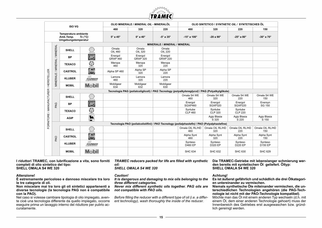
Die TRAMEC-Getriebe mit lebenslanger schmierung wer-den bereits mit syntetischen Öl geliefert. Öltyp: SHELL OMALA S4 WE 320
Achtung!Es ist äußerst gefährlich und schädlich die drei Ölkategori-en untereinander zu vermischen.Niemals synthetische Öle miteinander vermischen, die un-terschiedlichen Technologien angehören (die PAG-Tech-nologie ist nicht mit der PAO-Technologie kompatibel).Möchte man das Öl mit einem anderen Typ wechseln (d.h. mit einem Öl, dem einer anderen Technologie gehoert) muss der Innenbereich des Getriebes erst ausgewaschen bzw. gründ-lich gereinigt werden.
TRAMEC reducers packed for life are filled with synthetic oil: SHELL OMALA S4 WE 320
Caution!It is dangerous and damaging to mix oils belonging to the three different categories.Never mix different synthetic oils together. PAG oils are not compatible with PAO oils.
Before filling the reducer with a different type of oil (i.e. a differ-ent technology), wash thoroughly the inside of the reducer.
I riduttori TRAMEC, con lubrificazione a vita, sono forniti completi di olio sintetico del tipo:SHELL OMALA S4 WE 320
Attenzione!È estremamente pericoloso e dannoso miscelare tra loro le tre categorie di oli.Non miscelare mai tra loro gli oli sintetici appartenenti a diverse tecnologie (la tecnologia PAG non è compatibile con la PAO).Nel caso si volesse cambiare tipologia di olio impiegato, aven-te cioè una tecnologia differente da quello impiegato, occorre eseguire prima un lavaggio interno del riduttore per pulirlo ac-curatamente.
ISO VGOLIO MINERALE / MINERAL OIL - MINERALÖL OLIO SINTETICO / SYNTHETIC OIL / SYNTETISCHES ÖL
460 320 220 460 320 220 150Temperatura ambienteAmb.Temp. Tc (°C)Umgebungstemperatur
5° a 45° 0° a 40° -5° a 35° -15° a 100° -20 a 90° -25° a 80° -30° a 70°
FOR
NIT
OR
E /
MA
NU
FAC
TUR
ER
/ H
ER
STE
LLE
R
MIN
ER
ALE
/ M
INE
RA
L / M
INE
RA
L MINERALE / MINERAL / MINERAL
SHELL OmalaOIL 460
OmalaOIL 320
OmalaOIL 220
BP EnergolGRXP 460
EnergolGRXP 320
EnergolGRXP 220
TEXACO Meropa460
Meropa320
Meropa220
CASTROL Alpha SP 460 Alpha SP320
Alpha SP220
KLUBER Lamora460
Lamora320
Lamora220
MOBIL Mobilgear634
Mobilgear632
Mobilgear630
PAG
Tecnologia PAG (polialcoliglicoli) / PAG Tecnology (polyalkyleneglycol) / PAG (Polyalkylglikole)
SHELL Omala S4 WE460
Omala S4 WE320
Omala S4 WE 220
Omala S4 WE150
BP EnergolSGXP460
EnergolSGXP320
EnergolSGXP220
EnersynSG 150
TEXACO SynlubeCLP 460
SynlubeCLP 320
SynlubeCLP 220
AGIP Agip BlasiaS 320
Agip BlasiaS 220
Agip BlasiaS 150
PAO
Tecnologia PAO (polialcoliolifini) / PAO Tecnology (polialphaolefin) / PAO (Polyalphaolefine)
SHELL Omala OIL RL/HD 460
Omala OIL RL/HD 320
Omala OIL RL/HD 220
Omala OIL RL/HD 150
CASTROL Alpha Synt460
Alpha Synt320
Alpha Synt220
Alpha Synt150
KLUBER SyntesoD460 EP
SyntesoD320 EP
SyntesoD220 EP
SyntesoD150 EP
MOBIL SHC 634 SHC 632 SHC 630 SHC 629
16
Kegelstirnradgetriebe
Die Kegelstirnradgetriebe (die Typen TF56 und TF63 mit Schmierung auf Lebensdauer ausgenommen) sind für die Öl-schmierung ausgerüstet und mit Einfüll-,Ölstand-und Ablass-schrauben ausgestattet.Eine Pumpe für die Zwangsschmierung der oberen Lager kann auf den Baugrößen 125, 140, 160, 180, 200 und 225 in der Baulage VA auf Wunsch geliefert werden.Für die B6 und B7 Version ist eine Entlüftungsschraube mit Ölstandanzeigel vorgesehen.
Getriebe mit einer Rücklaufsperre müssen mit PAG syntheti-schem Oel (Viskosität ISO150) betrieben werden.
Baulage und Schmiermittelmenge (Liter)
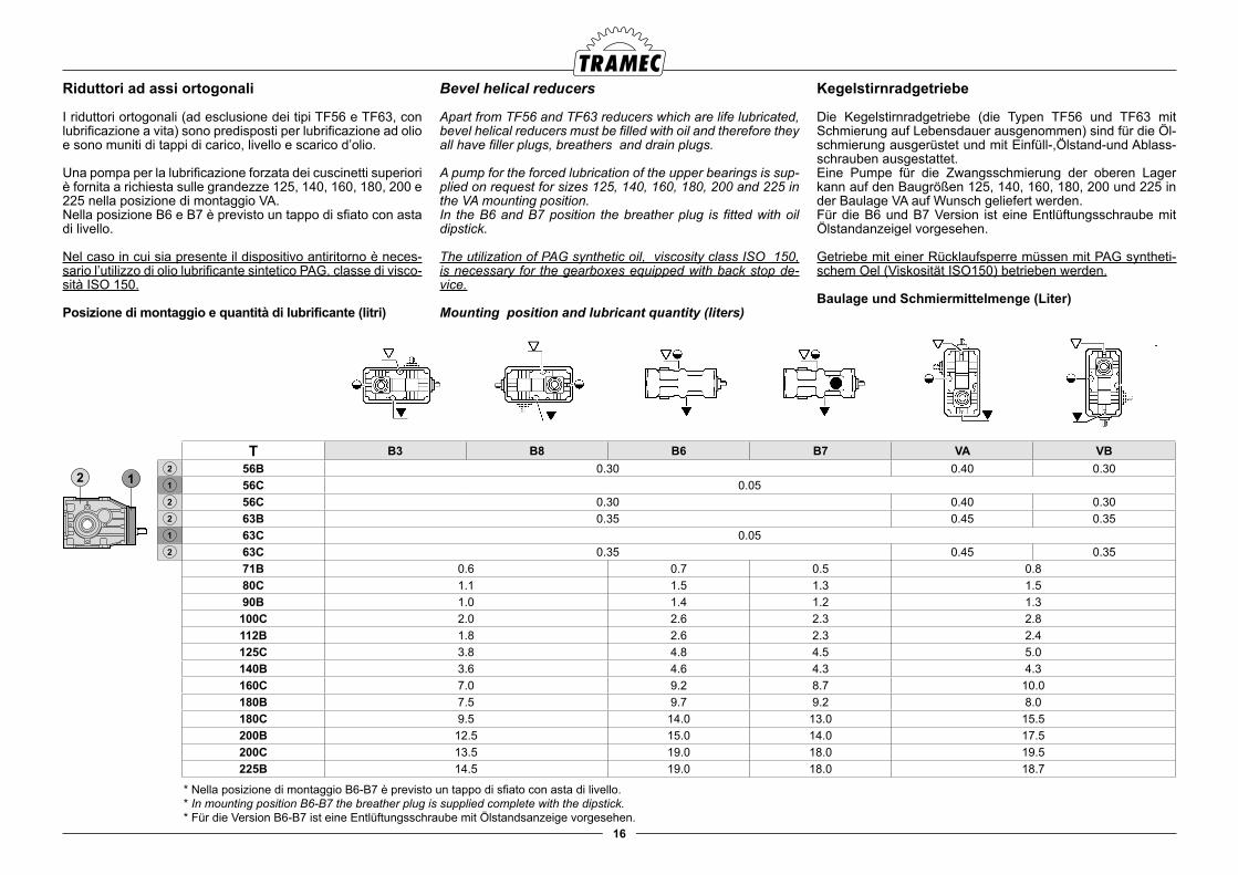
Bevel helical reducers
Apart from TF56 and TF63 reducers which are life lubricated, bevel helical reducers must be filled with oil and therefore they all have filler plugs, breathers and drain plugs.
A pump for the forced lubrication of the upper bearings is sup-plied on request for sizes 125, 140, 160, 180, 200 and 225 in the VA mounting position.In the B6 and B7 position the breather plug is fitted with oil dipstick.
The utilization of PAG synthetic oil, viscosity class ISO 150, is necessary for the gearboxes equipped with back stop de-vice.
Mounting position and lubricant quantity (liters)
Riduttori ad assi ortogonali
I riduttori ortogonali (ad esclusione dei tipi TF56 e TF63, con lubrificazione a vita) sono predisposti per lubrificazione ad olio e sono muniti di tappi di carico, livello e scarico d’olio.
Una pompa per la lubrificazione forzata dei cuscinetti superiori è fornita a richiesta sulle grandezze 125, 140, 160, 180, 200 e 225 nella posizione di montaggio VA.Nella posizione B6 e B7 è previsto un tappo di sfiato con asta di livello.
Nel caso in cui sia presente il dispositivo antiritorno è neces-sario l’utilizzo di olio lubrificante sintetico PAG, classe di visco-sità ISO 150.
Posizione di montaggio e quantità di lubrificante (litri)
* Nella posizione di montaggio B6-B7 è previsto un tappo di sfiato con asta di livello.* In mounting position B6-B7 the breather plug is supplied complete with the dipstick.* Für die Version B6-B7 ist eine Entlüftungsschraube mit Ölstandsanzeige vorgesehen.
T B3 B8 B6 B7 VA VB2 56B 0.30 0.40 0.301 56C 0.052 56C 0.30 0.40 0.302 63B 0.35 0.45 0.351 63C 0.052 63C 0.35 0.45 0.35
71B 0.6 0.7 0.5 0.880C 1.1 1.5 1.3 1.590B 1.0 1.4 1.2 1.3
100C 2.0 2.6 2.3 2.8112B 1.8 2.6 2.3 2.4125C 3.8 4.8 4.5 5.0140B 3.6 4.6 4.3 4.3160C 7.0 9.2 8.7 10.0180B 7.5 9.7 9.2 8.0180C 9.5 14.0 13.0 15.5200B 12.5 15.0 14.0 17.5200C 13.5 19.0 18.0 19.5225B 14.5 19.0 18.0 18.7
17
Parallelengetriebe
Die Parallelengetriebe werden für die Ölschmierung ausge-ruestet und mit entsprechenden Einfüll-, Pegelkontroll- und Ablassschrauben ausgestattet.Eine Pumpe für die Zwangsschmierung der oberen Lager kann auf den Baugrößen 125, 140, 160, 180, 200 und 225 in der Baulage VA auf Wunsch geliefert werden.
In den Baulagen V 1 und V3 ist jeweils eine Entlüftungsschrau-be mit Oelstandsanzeigel vorgesehen.
Getriebe mit einer Rücklaufsperre müssen mit PAG syntheti-schem Oel (Viskosität ISO150) betrieben werden.
Einbaulage und Schmiermittelmenge (Liter)
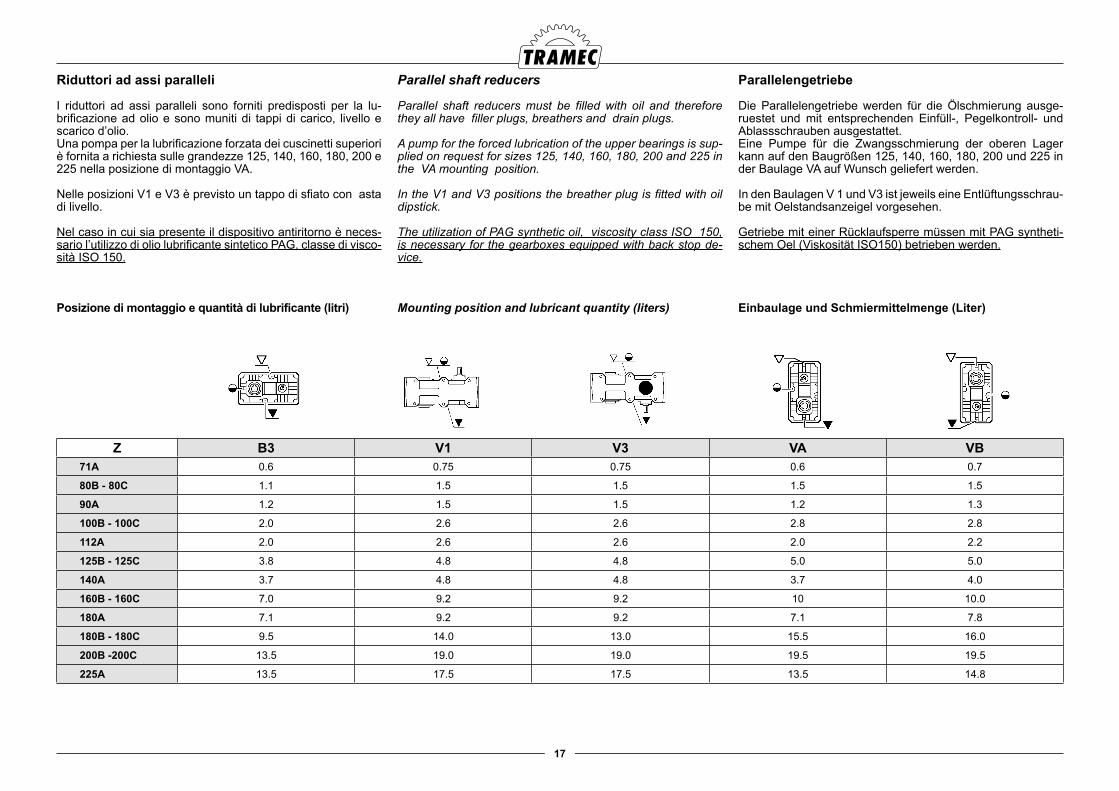
Parallel shaft reducers
Parallel shaft reducers must be filled with oil and therefore they all have filler plugs, breathers and drain plugs.
A pump for the forced lubrication of the upper bearings is sup-plied on request for sizes 125, 140, 160, 180, 200 and 225 in the VA mounting position.
In the V1 and V3 positions the breather plug is fitted with oil dipstick.
The utilization of PAG synthetic oil, viscosity class ISO 150, is necessary for the gearboxes equipped with back stop de-vice.
Mounting position and lubricant quantity (liters)
Riduttori ad assi paralleli
I riduttori ad assi paralleli sono forniti predisposti per la lu-brificazione ad olio e sono muniti di tappi di carico, livello e scarico d’olio.Una pompa per la lubrificazione forzata dei cuscinetti superiori è fornita a richiesta sulle grandezze 125, 140, 160, 180, 200 e 225 nella posizione di montaggio VA.
Nelle posizioni V1 e V3 è previsto un tappo di sfiato con asta di livello.
Nel caso in cui sia presente il dispositivo antiritorno è neces-sario l’utilizzo di olio lubrificante sintetico PAG, classe di visco-sità ISO 150.
Posizione di montaggio e quantità di lubrificante (litri)
Z B3 V1 V3 VA VB71A 0.6 0.75 0.75 0.6 0.7
80B - 80C 1.1 1.5 1.5 1.5 1.5
90A 1.2 1.5 1.5 1.2 1.3
100B - 100C 2.0 2.6 2.6 2.8 2.8
112A 2.0 2.6 2.6 2.0 2.2
125B - 125C 3.8 4.8 4.8 5.0 5.0
140A 3.7 4.8 4.8 3.7 4.0
160B - 160C 7.0 9.2 9.2 10 10.0
180A 7.1 9.2 9.2 7.1 7.8
180B - 180C 9.5 14.0 13.0 15.5 16.0
200B -200C 13.5 19.0 19.0 19.5 19.5
225A 13.5 17.5 17.5 13.5 14.8
18
Aufsteckgetriebe
Aufsteckgetriebe werden fuer die Oelschmierung ausgerues-tet und werden mit entsprechenden Einfuell-, Oestand- und Ablassschrauben ausgestattet.
Getriebe mit einer Rücklaufsperre müssen mit PAG syntheti-schem Oel (Viskosität ISO150) betrieben werden.
Einbaulage und Schmiermittelmenge (Liter)
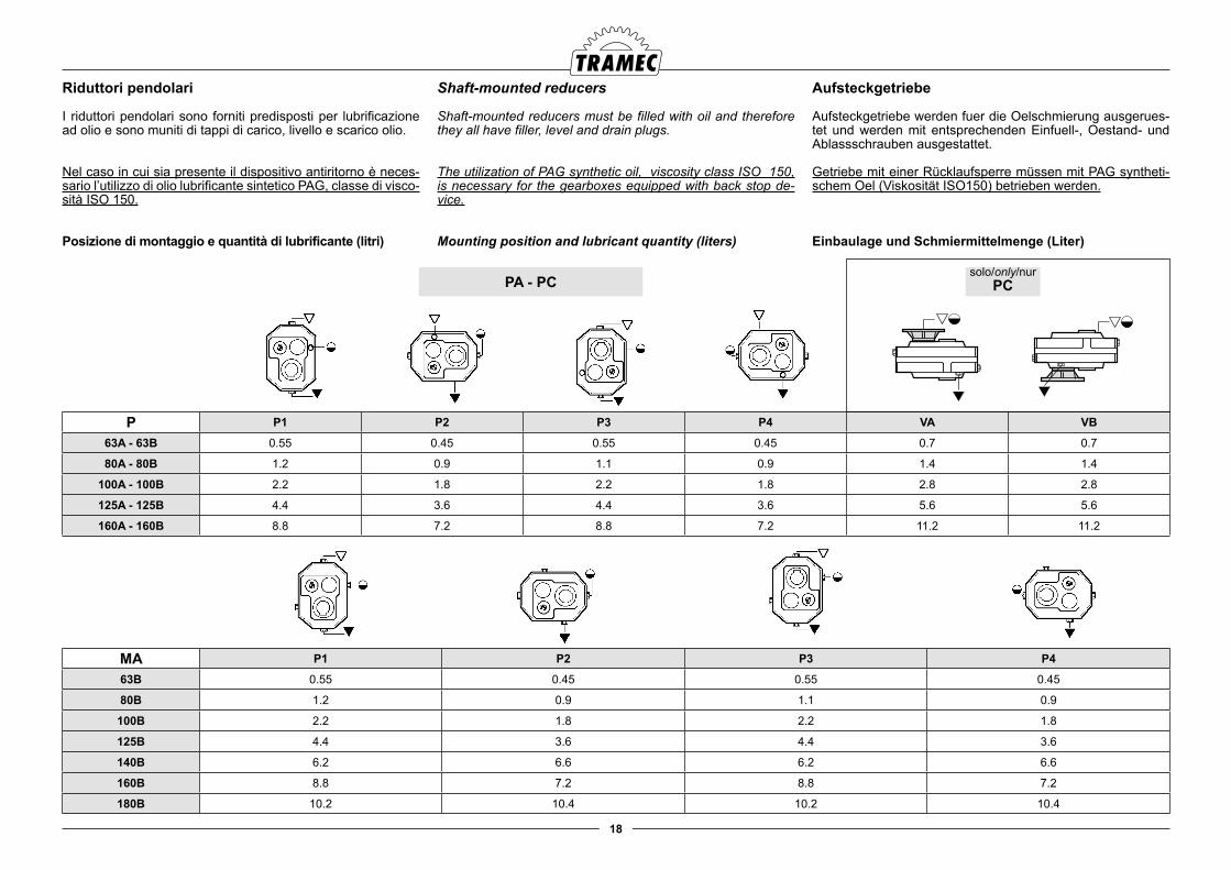
Shaft-mounted reducers
Shaft-mounted reducers must be filled with oil and therefore they all have filler, level and drain plugs.
The utilization of PAG synthetic oil, viscosity class ISO 150, is necessary for the gearboxes equipped with back stop de-vice.
Mounting position and lubricant quantity (liters)
Riduttori pendolari
I riduttori pendolari sono forniti predisposti per lubrificazione ad olio e sono muniti di tappi di carico, livello e scarico olio.
Nel caso in cui sia presente il dispositivo antiritorno è neces-sario l’utilizzo di olio lubrificante sintetico PAG, classe di visco-sità ISO 150.
Posizione di montaggio e quantità di lubrificante (litri)
P P1 P2 P3 P4 VA VB
63A - 63B 0.55 0.45 0.55 0.45 0.7 0.7
80A - 80B 1.2 0.9 1.1 0.9 1.4 1.4
100A - 100B 2.2 1.8 2.2 1.8 2.8 2.8
125A - 125B 4.4 3.6 4.4 3.6 5.6 5.6
160A - 160B 8.8 7.2 8.8 7.2 11.2 11.2
MA P1 P2 P3 P4
63B 0.55 0.45 0.55 0.45
80B 1.2 0.9 1.1 0.9
100B 2.2 1.8 2.2 1.8
125B 4.4 3.6 4.4 3.6
140B 6.2 6.6 6.2 6.6
160B 8.8 7.2 8.8 7.2
180B 10.2 10.4 10.2 10.4
PA - PCsolo/only/nur
PC
19
Winkelgetriebe
Winkelgetriebe (mit Ausnahme der R19 Größe, der lebenslang geschmiert ist) werden fuer di Oelschmierung ausgeruestest und werden mit entsprechenden Einfuell-, Oelstand- und Ab-lassschraube ausgestattet. Fur die B6 und B7 Version ist eine Entluftungsschraubeb mit Olstandanzeigel vorgesehen.
Einbaulage und Schmiermittelmenge (Liter)
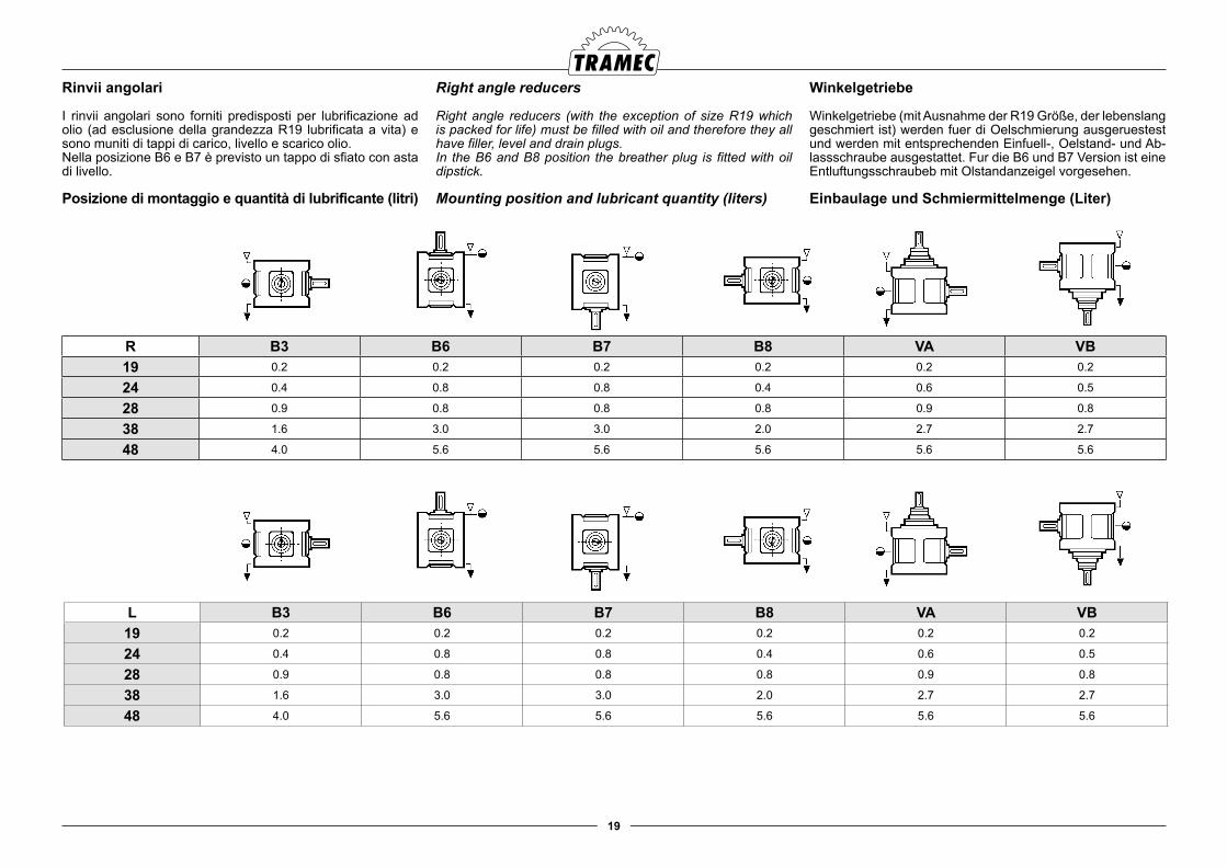
Right angle reducers
Right angle reducers (with the exception of size R19 which is packed for life) must be filled with oil and therefore they all have filler, level and drain plugs.In the B6 and B8 position the breather plug is fitted with oil dipstick.
Mounting position and lubricant quantity (liters)
Rinvii angolari
I rinvii angolari sono forniti predisposti per lubrificazione ad olio (ad esclusione della grandezza R19 lubrificata a vita) e sono muniti di tappi di carico, livello e scarico olio.Nella posizione B6 e B7 è previsto un tappo di sfiato con asta di livello.
Posizione di montaggio e quantità di lubrificante (litri)
R B3 B6 B7 B8 VA VB19 0.2 0.2 0.2 0.2 0.2 0.2
24 0.4 0.8 0.8 0.4 0.6 0.5
28 0.9 0.8 0.8 0.8 0.9 0.8
38 1.6 3.0 3.0 2.0 2.7 2.7
48 4.0 5.6 5.6 5.6 5.6 5.6
L B3 B6 B7 B8 VA VB19 0.2 0.2 0.2 0.2 0.2 0.2
24 0.4 0.8 0.8 0.4 0.6 0.5
28 0.9 0.8 0.8 0.8 0.9 0.8
38 1.6 3.0 3.0 2.0 2.7 2.7
48 4.0 5.6 5.6 5.6 5.6 5.6
20
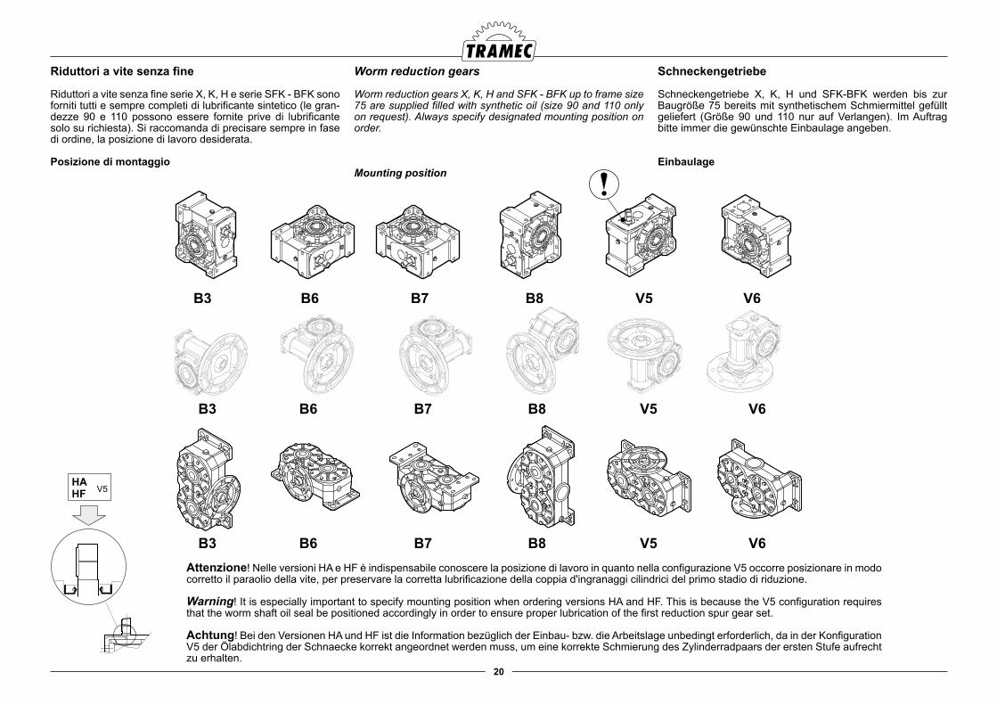
Schneckengetriebe
Schneckengetriebe X, K, H und SFK-BFK werden bis zur Baugröße 75 bereits mit synthetischem Schmiermittel gefüllt geliefert (Größe 90 und 110 nur auf Verlangen). Im Auftrag bitte immer die gewünschte Einbaulage angeben.
Einbaulage
Worm reduction gears
Worm reduction gears X, K, H and SFK - BFK up to frame size 75 are supplied filled with synthetic oil (size 90 and 110 only on request). Always specify designated mounting position on order.
Mounting position
Riduttori a vite senza fine
Riduttori a vite senza fine serie X, K, H e serie SFK - BFK sono forniti tutti e sempre completi di lubrificante sintetico (le gran-dezze 90 e 110 possono essere fornite prive di lubrificante solo su richiesta). Si raccomanda di precisare sempre in fase di ordine, la posizione di lavoro desiderata.
Posizione di montaggio
Attenzione! Nelle versioni HA e HF è indispensabile conoscere la posizione di lavoro in quanto nella configurazione V5 occorre posizionare in modo corretto il paraolio della vite, per preservare la corretta lubrificazione della coppia d'ingranaggi cilindrici del primo stadio di riduzione.
Warning! It is especially important to specify mounting position when ordering versions HA and HF. This is because the V5 configuration requires that the worm shaft oil seal be positioned accordingly in order to ensure proper lubrication of the first reduction spur gear set.
Achtung! Bei den Versionen HA und HF ist die Information bezüglich der Einbau- bzw. die Arbeitslage unbedingt erforderlich, da in der Konfiguration V5 der Ölabdichtring der Schnaecke korrekt angeordnet werden muss, um eine korrekte Schmierung des Zylinderradpaars der ersten Stufe aufrecht zu erhalten.
B3 B8 V5 V6B6 B7
B3 B8 V5 V6B6 B7
21
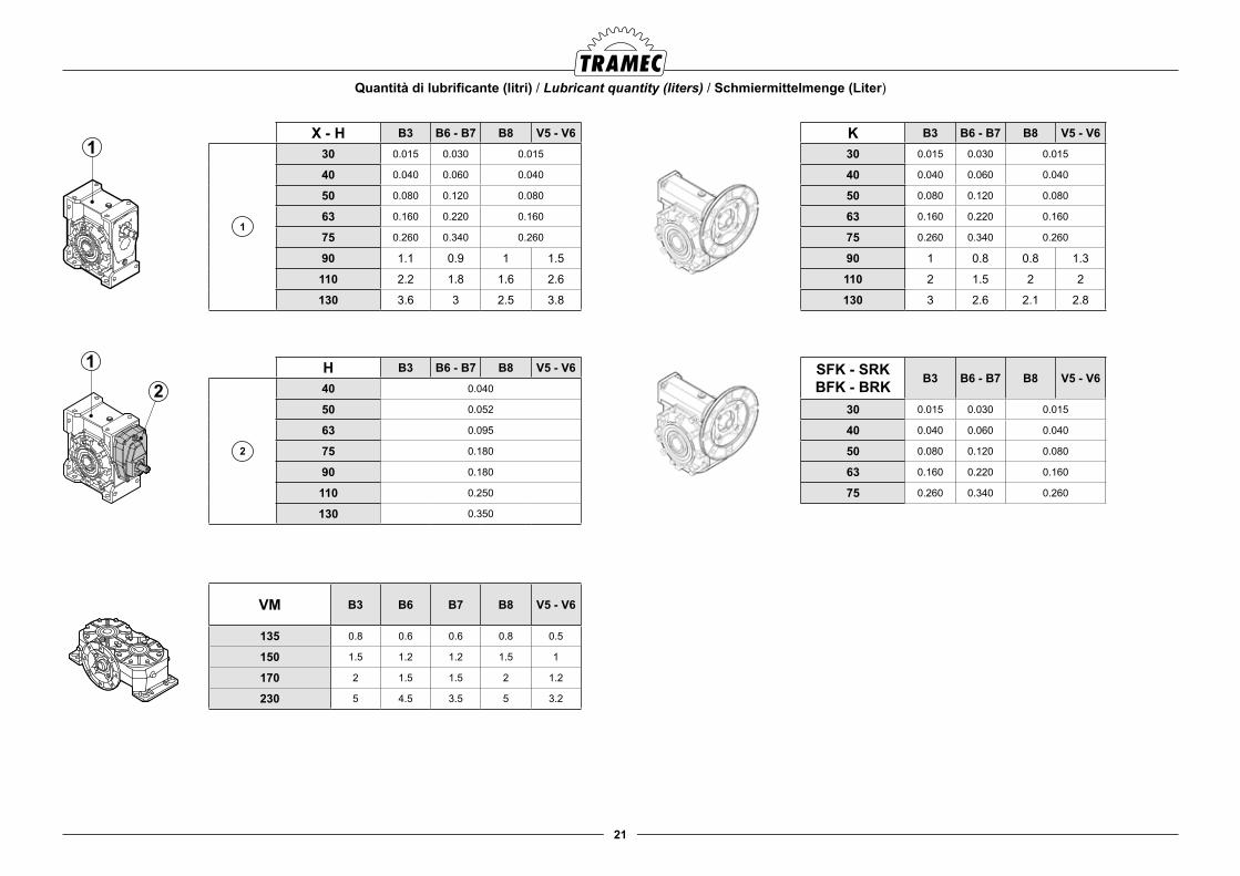
Quantità di lubrificante (litri) / Lubricant quantity (liters) / Schmiermittelmenge (Liter)
X - H B3 B6 - B7 B8 V5 - V6
1
30 0.015 0.030 0.015
40 0.040 0.060 0.040
50 0.080 0.120 0.080
63 0.160 0.220 0.160
75 0.260 0.340 0.260
90 1.1 0.9 1 1.5
110 2.2 1.8 1.6 2.6
130 3.6 3 2.5 3.8
H B3 B6 - B7 B8 V5 - V6
2
40 0.040
50 0.052
63 0.095
75 0.180
90 0.180
110 0.250
130 0.350
K B3 B6 - B7 B8 V5 - V6
30 0.015 0.030 0.015
40 0.040 0.060 0.040
50 0.080 0.120 0.080
63 0.160 0.220 0.160
75 0.260 0.340 0.260
90 1 0.8 0.8 1.3
110 2 1.5 2 2
130 3 2.6 2.1 2.8
SFK - SRKBFK - BRK B3 B6 - B7 B8 V5 - V6
30 0.015 0.030 0.015
40 0.040 0.060 0.040
50 0.080 0.120 0.080
63 0.160 0.220 0.160
75 0.260 0.340 0.260
VM B3 B6 B7 B8 V5 - V6
135 0.8 0.6 0.6 0.8 0.5
150 1.5 1.2 1.2 1.5 1
170 2 1.5 1.5 2 1.2
230 5 4.5 3.5 5 3.2
22
Vor der Inbetriebnahme muss folgendes überprüft werden:
● korrekte Montage des Getriebes und korrekter Ölstand
● korrekter Anschluss des Elektromotors
● korrekte, vom Motor bestimmten Drehrichtung
● bei Getrieben mit Rücklaufsperre soll die freie Drehrichtung mit der von Arbeitsmaschine bestimmten Drehrichtung übereinstimmen (eventuell in der blockierten Richtung erfolgenden Anläufe können zu irreparablen Schäden am Getriebe und/oder Motor führen).
Bei dem Leeranlauf von dreiphasig Asynchronmotoren (oder beim Anlauf mit geringer Last) ist folgendes notwendig: sanfter Anlauf
● niedriger Anzugsstrom
● beschränkte Belastungen
● Stern-Dreieck Schaltung (nomalerweise für Leistungen > 15 kW verwendet, nur ausnahmsweise geht der Wert auf 3 - 4 kW).
Eine Einlaufzeit von 200-400 Stunden mit einer reduzierten Last wird empfohlen, um dann die optimale Leistung zu erzielen (in dieser Pha-se sind höhere Temperaturen normal). Nach Ablauf der Einlaufzeit wird eine Anzugskontrolle an den Befestigungsschrauben empfohlen.RestgefahrRestgefahr ist eine Gefahr, die ein unvermeidbares nicht of-fensichtliches Risiko bedeutet.
Gefahr bei ÖlverlustDie Fläche mit nackten Händen nicht berühren.Wartungsarbeiten nur nach Nachsehen in dem Wartungsan-leitung führen.Bei unbeabsichtigten Kontakt:- kein Öl schlucken- sich selbst und Augen insbesondere nicht berühren - die in Berührung gekommenen Haut mit reichlich fließendem Wasser auswaschen.Wichtig: regelmäßig soll geprüft werden, dass es unter der Maschine keine Ölverluste gibt, die Abrutschen verursachen könnten. Arbeiter sol-len immer Sicherheitsschuhe tragen wenn in der Nähe der Maschine.-Gefahr bei heißen GetriebegehäusenDas Getriebegehäuse nicht mit nackten Händen berühren. Wartungsarbeiten führen, nur nachdem das Gehäuse abge-kühlt ist. Sicherheitshandschuhe sind immer zu tragen.
Check the following before starting-up the reducer:
● the reducer is correctly installed and filled with the correct amount of lubricant
● the electric motor is correctly connected
● the direction of rotation brought about by the installed motor is as required
● the free rotation direction of reducers featuring back stop device coincides with that required by the machine (starts in the locked direction may cause irreversible damage to the reducer and/or the motor).
If three-phase asynchronous motors are subject to a loadless or reduced load start, they should:
● be gently started
● have low starting current
● be subject to limited stress
● feature star-delta starting (normally for power values > 15 kW, down to 3-4 kW only in exceptional cases).
A running-in time of 200-400 hours featuring a reduced load is recommended to achieve peak efficiency. Higher tempera-tures are normal at this stage. Please check for possible loos-ening of the fastening screws after running in the reducer.Residual risksResidual risks are those potential dangers which is not pos-sible to eliminate totally and which could cause damages to the operator should he intervene in the wrong way.Risks in case of oil leakageDo not touch the leakage area with bare hands, any mainte-nance job should only be carried out after careful reading of the instruction manual. In case of contact with oil:- do not swallow it- do not touch your body, specially the eyes- wash with running water the part which has come in contact with oilImportant: check at regular intervals that there are no leak-ages under the machine in order to prevent people from slip-ping. People should always wear safety shoes when near a machine.-risks in case of hot gearbox housingsdo not touch the gearbox housing with bare hands. Before car-rying our any maintenance job, wait until it cools down. Always wear work gloves.
Prima della messa in servizio verificare che:
● Il riduttore sia montato correttamente e che il livello del lubrificante sia corretto
● il collegamento del motore elettrico sia corretto
● il senso di rotazione derminato dal motore installato sia quello voluto
● nei riduttori forniti con dispositivo antiritorno il senso di rotazione libero coincida con quello richiesto dalla macchina operatrice (eventuali avviamenti nel senso bloccato possono danneggiare irrimediabilmente il riduttore e/o il motore).
Con motori asincroni trifase, quando l’avviamento è a vuoto (o comunque a carico molto ridotto) è necessario avere:
● avviamenti dolci
● correnti di spunto basse
● sollecitazioni contenute
● avviamento stella-triangolo (normalmente per potenze > 15 kW, solo eccezionalmente si scende fino a 3 - 4 kW)
Si consiglia un rodaggio di 200-400 ore con carico ridotto per rag-giungere un rendimento ottimale (livelli di temperatura più elevati sono da considerarsi normali in questa fase); al termine del rodag-gio si consiglia una verifica del serraggio delle viti di fissaggio.Rischi Residui.Per rischio residuo si intende un potenziale pericolo, impossibile da eliminare o parzialmente eliminato,che può provocare danni all'ope-ratore se interviene con metodi e pratiche di lavoro non corrette.Pericolo in caso di perdita di olio.- Non toccate a mani nude la zona della perdita, non eseguire nessuni tipo di manutenzione senza aver prima consultato il manuale di istruzioni.In caso di contatto con l'olio:- non ingeritelo.- non toccatevi da nessuna parte, in particolare gli occhi.- lavatevi la zona di contatto con acqua corrente.Attenzione: controllate periodicamente che non ci siano per-dite di olio sotto la macchina, in modo da evitare di scivolare, si ricorda di usare sempre scarpe antinfortunistiche nelle vici-nanze della macchina.- Pericolo di calore sulle carcasse dei riduttori.Non toccate a mani nude la carcassa del riduttore, in caso di manutenzione aspettare che si raffreddi. Si raccomanda di usare guanti di protezione.
5.0 MESSA IN SERVIZIO 5.0 STARTING-UP 5.0 INBETRIEBNAHME
23
Während des Betriebs müssen regelmäßig eventuelle Schwin-gungen, die Temperatur und den Geräuschpegel überprüft werden, ebenso ist eine Kontrolle an den Dichtungen erfor-derlich.
Achtung!
Vor Beginn der Instandhaltungsarbeiten muss man sich darü-ber vergewissern, dass die Maschine sich im Stillstand befin-det und die Stromversorgung abgeschaltet ist. Darüberhinaus muss es kontrolliert werden, dass die Öltemperatur unter das Sicherheitsniveau abgesunken ist, um zu vermeinden, dass sich die Bediener damit verbrennen können.
Bei stehender Maschine folgendes kontrollieren:
● den Schmiermittelpegel
● das Verderben des Schmiermittels, ggf. auswechseln
● dass die Luftpassagen nicht verstopft sind
● dass die Außenflächen des Getriebes sauber sind, so dass ein korrekter Wärmeabbau garantiert werden kann
● den korrekten Anzug der Befestigungsschrauben
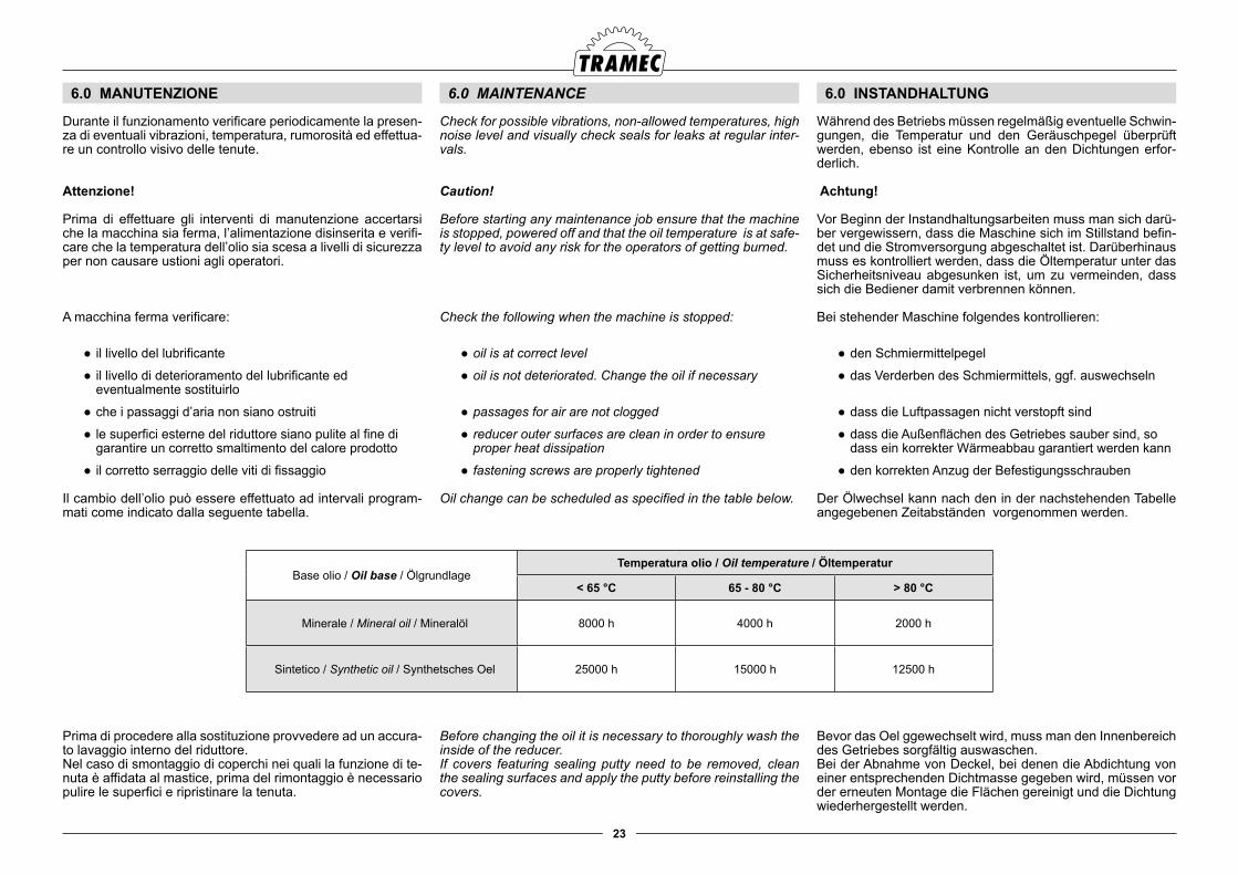
Der Ölwechsel kann nach den in der nachstehenden Tabelle angegebenen Zeitabständen vorgenommen werden.
Bevor das Oel ggewechselt wird, muss man den Innenbereich des Getriebes sorgfältig auswaschen.Bei der Abnahme von Deckel, bei denen die Abdichtung von einer entsprechenden Dichtmasse gegeben wird, müssen vor der erneuten Montage die Flächen gereinigt und die Dichtung wiederhergestellt werden.
Check for possible vibrations, non-allowed temperatures, high noise level and visually check seals for leaks at regular inter-vals.
Caution!
Before starting any maintenance job ensure that the machine is stopped, powered off and that the oil temperature is at safe-ty level to avoid any risk for the operators of getting burned.
Check the following when the machine is stopped:
● oil is at correct level
● oil is not deteriorated. Change the oil if necessary
● passages for air are not clogged
● reducer outer surfaces are clean in order to ensure proper heat dissipation
● fastening screws are properly tightened
Oil change can be scheduled as specified in the table below.
Before changing the oil it is necessary to thoroughly wash the inside of the reducer.If covers featuring sealing putty need to be removed, clean the sealing surfaces and apply the putty before reinstalling the covers.
Durante il funzionamento verificare periodicamente la presen-za di eventuali vibrazioni, temperatura, rumorosità ed effettua-re un controllo visivo delle tenute.
Attenzione!
Prima di effettuare gli interventi di manutenzione accertarsi che la macchina sia ferma, l’alimentazione disinserita e verifi-care che la temperatura dell’olio sia scesa a livelli di sicurezza per non causare ustioni agli operatori.
A macchina ferma verificare:
● il livello del lubrificante
● il livello di deterioramento del lubrificante ed eventualmente sostituirlo
● che i passaggi d’aria non siano ostruiti
● le superfici esterne del riduttore siano pulite al fine di garantire un corretto smaltimento del calore prodotto
● il corretto serraggio delle viti di fissaggio
Il cambio dell’olio può essere effettuato ad intervali program-mati come indicato dalla seguente tabella.
Prima di procedere alla sostituzione provvedere ad un accura-to lavaggio interno del riduttore.Nel caso di smontaggio di coperchi nei quali la funzione di te-nuta è affidata al mastice, prima del rimontaggio è necessario pulire le superfici e ripristinare la tenuta.
6.0 MANUTENZIONE 6.0 MAINTENANCE 6.0 INSTANDHALTUNG
Base olio / Oil base / ÖlgrundlageTemperatura olio / Oil temperature / Öltemperatur
< 65 °C 65 - 80 °C > 80 °C
Minerale / Mineral oil / Mineralöl 8000 h 4000 h 2000 h
Sintetico / Synthetic oil / Synthetsches Oel 25000 h 15000 h 12500 h
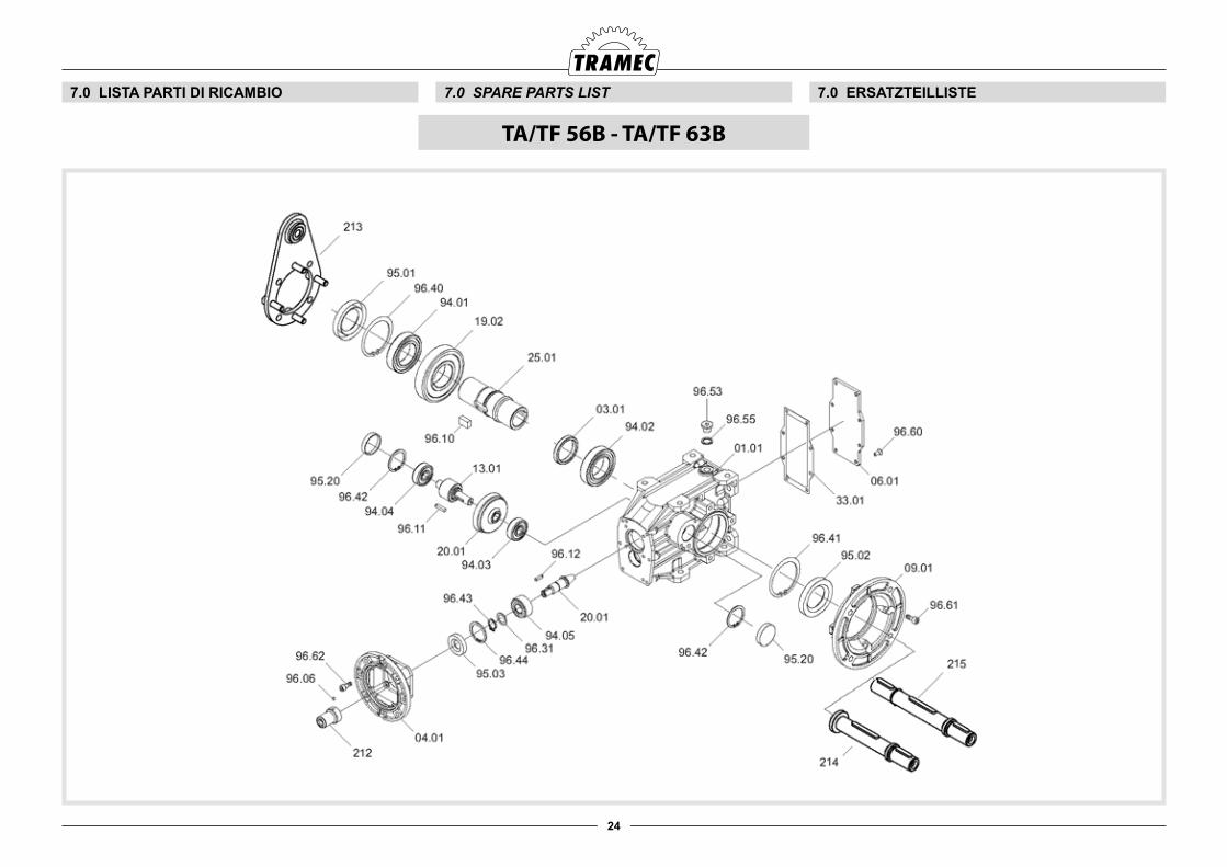
24
7.0 LISTA PARTI DI RICAMBIO 7.0 SPARE PARTS LIST 7.0 ERSATZTEILLISTE
TA/TF 56B - TA/TF 63B
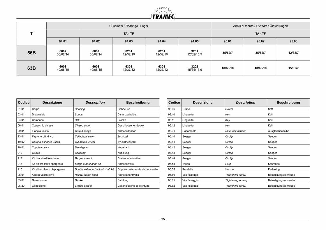
25
T
Cuscinetti / Bearings / Lager Anelli di tenuta / Oilseals / Öldichtungen
TA - TF TA - TF
94.01 94.02 94.03 94.04 94.05 95.01 95.02 95.03
56B 600735/62/14
600735/62/14
620112/32/10
620112/32/10
320112/32/15.9 35/62/7 35/62/7 12/32/7
63B 600840/68/15
600840/68/15
630112/37/12
630112/37/12
320215/35/15.9 40/68/10 40/68/10 15/35/7
Codice Descrizione Description Beschreibung
01.01 Corpo Housing Gehaeuse
03.01 Distanziale Spacer Distanzscheibe
04.01 Campana Bell Glocke
06.01 Coperchio chiuso Closed cover Geschlossener deckel
09.01 Flangia uscita Output flange Abtriebsflansch
13.01 Pignone cilindrico Cylindrical pinion Zyl.ritzel
19.02 Corona cilindrica uscita Cyl.output wheel Zyl.abtriebsrad
20.01 Coppia conica Bevel gear Kegelrad
212 Giunto Coupling Kupplung
213 Kit braccio di reazione Torque arm kit Drehmomentstütze
214 Kit albero lento sporgente Single output shaft kit Abtriebswelle
215 Kit albero lento bisporgente Double extended output shaft kit Doppelvorstehende abtriebswelle
25.01 Albero uscita cavo Hollow output shaft Abtriebshohlwelle
33.01 Guarnizione Gasket Dichtung
95.20 Cappellotto Closed oilseal Geschlossene oeldichtung
Codice Descrizione Description Beschreibung
96.06 Grano Dowel Stift
96.10 Linguetta Key Keil
96.11 Linguetta Key Keil
96.12 Linguetta Key Keil
96.31 Rasamento Shim adjustment Ausgleichscheibe
96.40 Seeger Circlip Seeger
96.41 Seeger Circlip Seeger
96.42 Seeger Circlip Seeger
96.43 Seeger Circlip Seeger
96.44 Seeger Circlip Seeger
96.53 Tappo Plug Schraube
96.55 Rondella Washer Federring
96.60 Vite fissaggio TIghtening screw Befestigungsschraube
96.61 Vite fissaggio TIghtening screwg Befestigungsschraube
96.62 Vite fissaggio TIghtening screw Befestigungsschraube
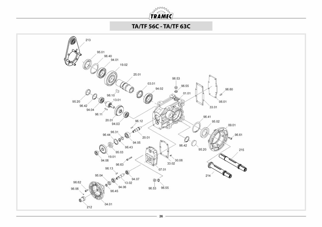
26
TA/TF 56C - TA/TF 63C
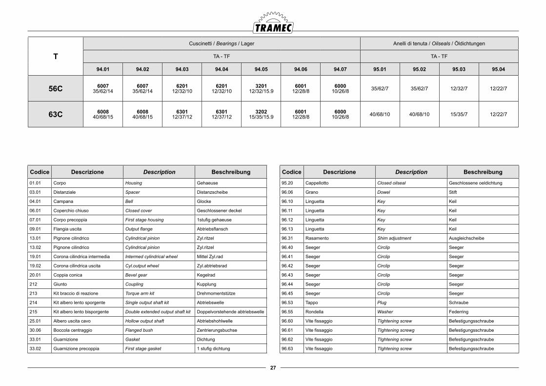
27
T
Cuscinetti / Bearings / Lager Anelli di tenuta / Oilseals / Öldichtungen
TA - TF TA - TF
94.01 94.02 94.03 94.04 94.05 94.06 94.07 95.01 95.02 95.03 95.04
56C 600735/62/14
600735/62/14
620112/32/10
620112/32/10
320112/32/15.9
600112/28/8
600010/26/8 35/62/7 35/62/7 12/32/7 12/22/7
63C 600840/68/15
600840/68/15
630112/37/12
630112/37/12
320215/35/15.9
600112/28/8
600010/26/8 40/68/10 40/68/10 15/35/7 12/22/7
Codice Descrizione Description Beschreibung
01.01 Corpo Housing Gehaeuse
03.01 Distanziale Spacer Distanzscheibe
04.01 Campana Bell Glocke
06.01 Coperchio chiuso Closed cover Geschlossener deckel
07.01 Corpo precoppia First stage housing 1stufig gehaeuse
09.01 Flangia uscita Output flange Abtriebsflansch
13.01 Pignone cilindrico Cylindrical pinion Zyl.ritzel
13.02 Pignone cilindrico Cylindrical pinion Zyl.ritzel
19.01 Corona cilindrica intermedia Intermed cylindrical wheel Mittel Zyl.rad
19.02 Corona cilindrica uscita Cyl.output wheel Zyl.abtriebsrad
20.01 Coppia conica Bevel gear Kegelrad
212 Giunto Coupling Kupplung
213 Kit braccio di reazione Torque arm kit Drehmomentstütze
214 Kit albero lento sporgente Single output shaft kit Abtriebswelle
215 Kit albero lento bisporgente Double extended output shaft kit Doppelvorstehende abtriebswelle
25.01 Albero uscita cavo Hollow output shaft Abtriebshohlwelle
30.06 Boccola centraggio Flanged bush Zentrierungsbuchse
33.01 Guarnizione Gasket Dichtung
33.02 Guarnizione precoppia First stage gasket 1 stufig dichtung
Codice Descrizione Description Beschreibung
95.20 Cappellotto Closed oilseal Geschlossene oeldichtung
96.06 Grano Dowel Stift
96.10 Linguetta Key Keil
96.11 Linguetta Key Keil
96.12 Linguetta Key Keil
96.13 Linguetta Key Keil
96.31 Rasamento Shim adjustment Ausgleichscheibe
96.40 Seeger Circlip Seeger
96.41 Seeger Circlip Seeger
96.42 Seeger Circlip Seeger
96.43 Seeger Circlip Seeger
96.44 Seeger Circlip Seeger
96.45 Seeger Circlip Seeger
96.53 Tappo Plug Schraube
96.55 Rondella Washer Federring
96.60 Vite fissaggio TIghtening screw Befestigungsschraube
96.61 Vite fissaggio TIghtening screwg Befestigungsschraube
96.62 Vite fissaggio TIghtening screw Befestigungsschraube
96.63 Vite fissaggio TIghtening screw Befestigungsschraube
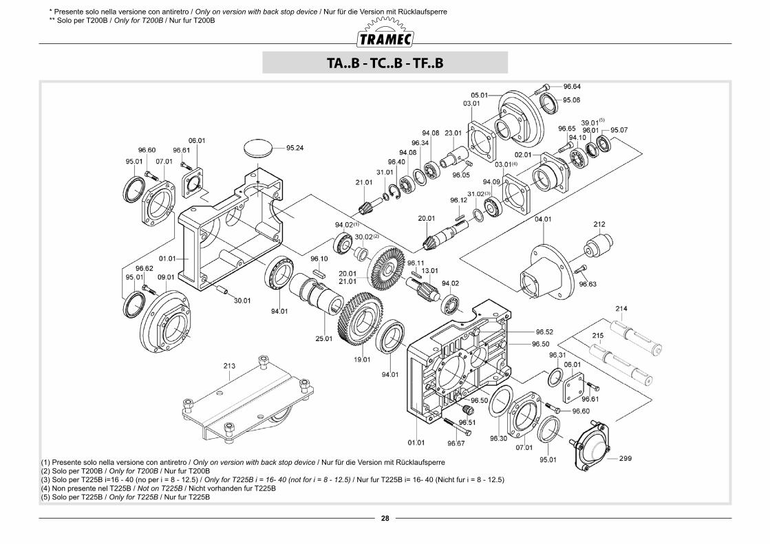
28
TA..B - TC..B - TF..B
* Presente solo nella versione con antiretro / Only on version with back stop device / Nur für die Version mit Rücklaufsperre** Solo per T200B / Only for T200B / Nur fur T200B
(1) Presente solo nella versione con antiretro / Only on version with back stop device / Nur für die Version mit Rücklaufsperre(2) Solo per T200B / Only for T200B / Nur fur T200B(3) Solo per T225B i=16 - 40 (no per i = 8 - 12.5) / Only for T225B i = 16- 40 (not for i = 8 - 12.5) / Nur fur T225B i= 16- 40 (Nicht fur i = 8 - 12.5)(4) Non presente nel T225B / Not on T225B / Nicht vorhanden fur T225B(5) Solo per T225B / Only for T225B / Nur fur T225B
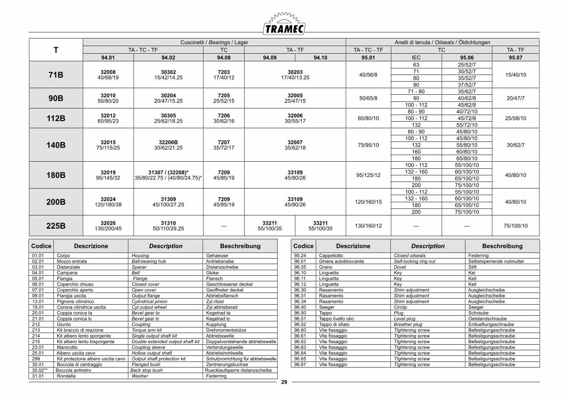
29
TCuscinetti / Bearings / Lager Anelli di tenuta / Oilseals / Öldichtungen
TA - TC - TF TC TA - TF TA - TC - TF TC TA - TF94.01 94.02 94.08 94.09 94.10 95.01 IEC 95.06 95.07
71B 3200840/68/19
3030215/42/14.25
720317/40/12
3020317/40/13.25 40/56/8
63 25/52/7
15/40/1071 30/52/780 35/52/790 37/52/7
90B 3201050/80/20
3020420/47/15.25
720525/52/15
3200525/47/15 50/65/8
71 - 80 35/62/720/47/790 40/62/8
100 - 112 45/62/8
112B 3201260/95/23
3030525/62/18.25
720630/62/16
3200630/55/17 60/80/10
80 - 90 40/72/1025/58/10100 - 112 45/72/8
132 55/72/10
140B 3201575/115/25
32206B30/62/21.25
720735/72/17
3200735/62/18 75/95/10
80 - 90 45/80/10
30/62/7100 - 112 45/80/10
132 55/80/10160 60/80/10180 65/80/10
180B 3201995/145/32
31307 / (32208)*35/80/22.75 / (40/80/24.75)*
720945/85/19
3310945/80/26 95/125/12
100 - 112 55/100/10
40/80/10132 - 160 60/100/10180 65/100/10200 75/100/10
200B 32024120/180/38
3130945/100/27.25
720945/85/19
3310945/80/26 120/160/15
100 - 112 55/100/10
40/80/10132 - 160 60/100/10180 65/100/10200 75/100/10
225B 32026130/200/45
3131050/110/29.25 — 33211
55/100/3533211
55/100/35 130/160/12 — — 75/100/10
Codice Descrizione Description Beschreibung 01.01 Corpo Housing Gehaeuse 02.01 Mozzo entrata Ball-bearing hub Antriebsnabe 03.01 Distanziale Spacer Distanzscheibe 04.01 Campana Bell Gloke 05.01 Flangia Flange Flansch 06.01 Coperchio chiuso Closed cover Geschlossener deckel 07.01 Coperchio aperto Open cover Geoffneter deckel 09.01 Flangia uscita Output flange Abtriebsflansch 13.01 Pignone cilindrico Cylindrical pinion Zyl.ritzel 19.01 Corona cilindrica uscita Cyl.output wheel Zyl.abtriebsrad 20.01 Coppia conica ta Bevel gear ta Kegelrad ta 21.01 Coppia conica tc Bevel gear tc Kegelrad tc 212 Giunto Coupling Kupplung 213 Kit braccio di reazione Torque arm kit Drehmomentstütze 214 Kit albero lento sporgente Single output shaft kit Abtriebswelle 215 Kit albero lento bisporgente Double extended output shaft kit Doppelvorstehende abtriebswelle 23.01 Manicotto Coupling sleeve Verbindungswelle 25.01 Albero uscita cavo Hollow output shaft Abtriebshohlwelle 299 Kit protezione albero uscita cavo Output shaft protection kit Schutzvorrichtung für abtriebswelle 30.01 Boccola di centraggio Flanged bush Zentrierungsbuchse 30.02** Boccola antiretro Back stop bush Ruecklaufsperre distanzscheibe 31.01 Rondella Washer Federring
Codice Descrizione Description Beschreibung 95.24 Cappellotto Closed oilseals Federring 96.01 Ghiera autobloccante Self-locking ring nut Selbstsperrende nutmutter 96.05 Grano Dovel Stift 96.10 Linguetta Key Kei 96.11 Linguetta Key Keil 96.12 Linguetta Key Keil 96.30 Rasamento Shim adjustment Ausgleichscheibe 96.31 Rasamento Shim adjustment Ausgleichscheibe 96.34 Rasamento Shim adjustment Ausgleichscheibe 96.40 Seeger Circlip Seeger 96.50 Tappo Plug Schraube 96.51 Tappo livello olio Level plug Oelstandschraube 96.52 Tappo di sfiato Breather plug Entlueftungsschraube 96.60 Vite fissaggio TIghtening screw Befestigungsschraube 96.61 Vite fissaggio TIghtening screw Befestigungsschraube 96.62 Vite fissaggio TIghtening screw Befestigungsschraube 96.63 Vite fissaggio TIghtening screw Befestigungsschraube 96.64 Vite fissaggio TIghtening screw Befestigungsschraube 96.65 Vite fissaggio TIghtening screw Befestigungsschraube 96.67 Vite fissaggio TIghtening screw Befestigungsschraube
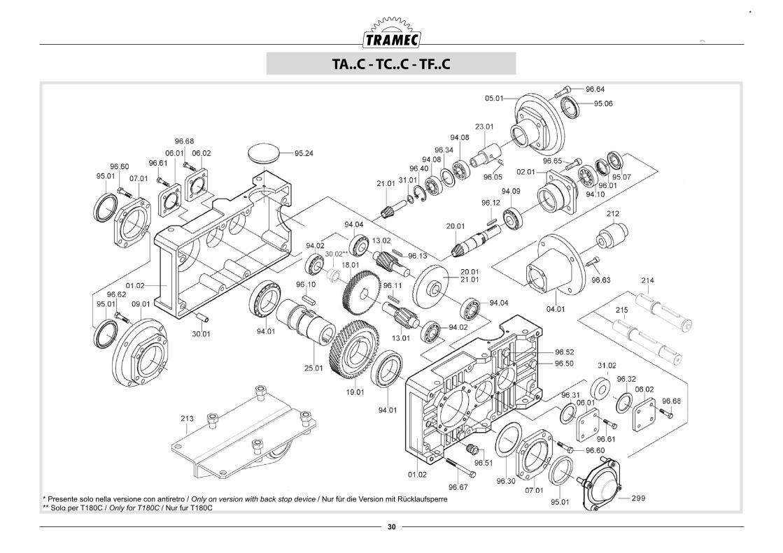
30
TA..C - TC..C - TF..C
30.02**
*
* Presente solo nella versione con antiretro / Only on version with back stop device / Nur für die Version mit Rücklaufsperre** Solo per T180C / Only for T180C / Nur fur T180C
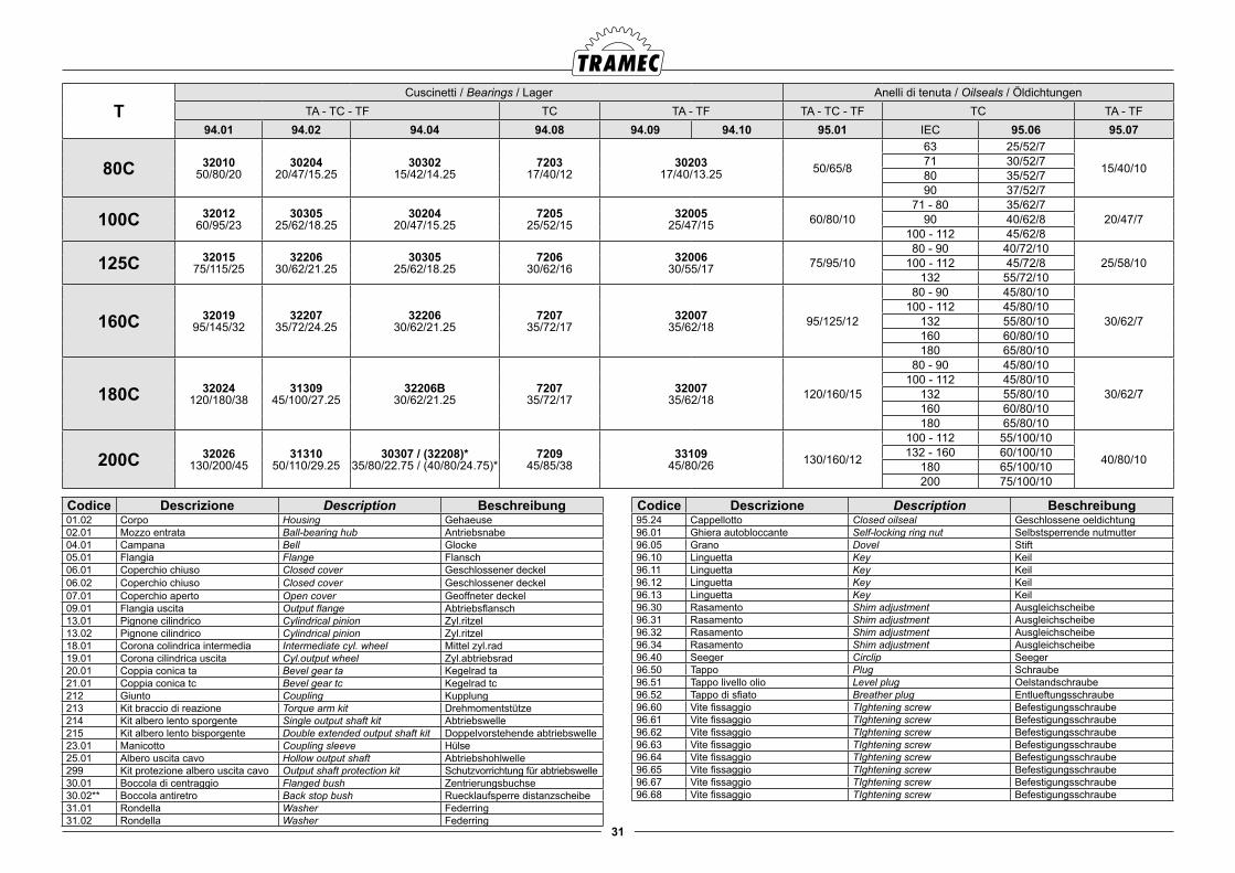
31
TCuscinetti / Bearings / Lager Anelli di tenuta / Oilseals / Öldichtungen
TA - TC - TF TC TA - TF TA - TC - TF TC TA - TF94.01 94.02 94.04 94.08 94.09 94.10 95.01 IEC 95.06 95.07
80C 3201050/80/20
3020420/47/15.25
3030215/42/14.25
720317/40/12
3020317/40/13.25 50/65/8
63 25/52/7
15/40/1071 30/52/780 35/52/790 37/52/7
100C 3201260/95/23
3030525/62/18.25
3020420/47/15.25
720525/52/15
3200525/47/15 60/80/10
71 - 80 35/62/720/47/790 40/62/8
100 - 112 45/62/8
125C 3201575/115/25
3220630/62/21.25
3030525/62/18.25
720630/62/16
3200630/55/17 75/95/10
80 - 90 40/72/1025/58/10100 - 112 45/72/8
132 55/72/10
160C 3201995/145/32
3220735/72/24.25
3220630/62/21.25
720735/72/17
3200735/62/18 95/125/12
80 - 90 45/80/10
30/62/7100 - 112 45/80/10
132 55/80/10160 60/80/10180 65/80/10
180C 32024120/180/38
3130945/100/27.25
32206B30/62/21.25
720735/72/17
3200735/62/18 120/160/15
80 - 90 45/80/10
30/62/7100 - 112 45/80/10
132 55/80/10160 60/80/10180 65/80/10
200C 32026130/200/45
3131050/110/29.25
30307 / (32208)*35/80/22.75 / (40/80/24.75)*
720945/85/38
3310945/80/26 130/160/12
100 - 112 55/100/10
40/80/10132 - 160 60/100/10180 65/100/10200 75/100/10
Codice Descrizione Description Beschreibung01.02 Corpo Housing Gehaeuse02.01 Mozzo entrata Ball-bearing hub Antriebsnabe 04.01 Campana Bell Glocke05.01 Flangia Flange Flansch06.01 Coperchio chiuso Closed cover Geschlossener deckel06.02 Coperchio chiuso Closed cover Geschlossener deckel07.01 Coperchio aperto Open cover Geoffneter deckel09.01 Flangia uscita Output flange Abtriebsflansch13.01 Pignone cilindrico Cylindrical pinion Zyl.ritzel 13.02 Pignone cilindrico Cylindrical pinion Zyl.ritzel 18.01 Corona colindrica intermedia Intermediate cyl. wheel Mittel zyl.rad19.01 Corona cilindrica uscita Cyl.output wheel Zyl.abtriebsrad20.01 Coppia conica ta Bevel gear ta Kegelrad ta21.01 Coppia conica tc Bevel gear tc Kegelrad tc212 Giunto Coupling Kupplung213 Kit braccio di reazione Torque arm kit Drehmomentstütze214 Kit albero lento sporgente Single output shaft kit Abtriebswelle215 Kit albero lento bisporgente Double extended output shaft kit Doppelvorstehende abtriebswelle23.01 Manicotto Coupling sleeve Hülse25.01 Albero uscita cavo Hollow output shaft Abtriebshohlwelle299 Kit protezione albero uscita cavo Output shaft protection kit Schutzvorrichtung für abtriebswelle30.01 Boccola di centraggio Flanged bush Zentrierungsbuchse30.02** Boccola antiretro Back stop bush Ruecklaufsperre distanzscheibe31.01 Rondella Washer Federring31.02 Rondella Washer Federring
Codice Descrizione Description Beschreibung95.24 Cappellotto Closed oilseal Geschlossene oeldichtung96.01 Ghiera autobloccante Self-locking ring nut Selbstsperrende nutmutter96.05 Grano Dovel Stift96.10 Linguetta Key Keil96.11 Linguetta Key Keil96.12 Linguetta Key Keil96.13 Linguetta Key Keil96.30 Rasamento Shim adjustment Ausgleichscheibe96.31 Rasamento Shim adjustment Ausgleichscheibe96.32 Rasamento Shim adjustment Ausgleichscheibe96.34 Rasamento Shim adjustment Ausgleichscheibe96.40 Seeger Circlip Seeger96.50 Tappo Plug Schraube96.51 Tappo livello olio Level plug Oelstandschraube96.52 Tappo di sfiato Breather plug Entlueftungsschraube96.60 Vite fissaggio TIghtening screw Befestigungsschraube96.61 Vite fissaggio TIghtening screw Befestigungsschraube96.62 Vite fissaggio TIghtening screw Befestigungsschraube96.63 Vite fissaggio TIghtening screw Befestigungsschraube96.64 Vite fissaggio TIghtening screw Befestigungsschraube96.65 Vite fissaggio TIghtening screw Befestigungsschraube96.67 Vite fissaggio TIghtening screw Befestigungsschraube96.68 Vite fissaggio TIghtening screw Befestigungsschraube
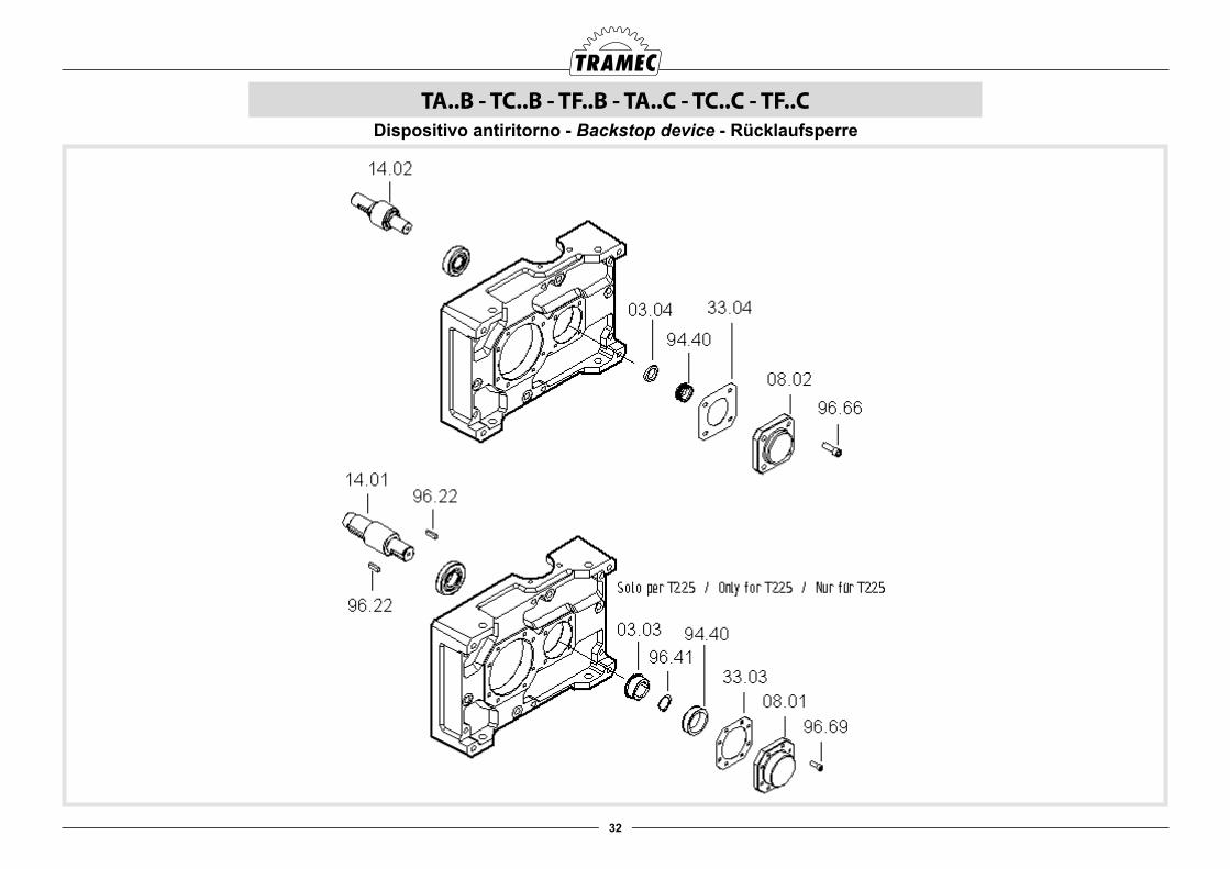
32
TA..B - TC..B - TF..B - TA..C - TC..C - TF..CDispositivo antiritorno - Backstop device - Rücklaufsperre
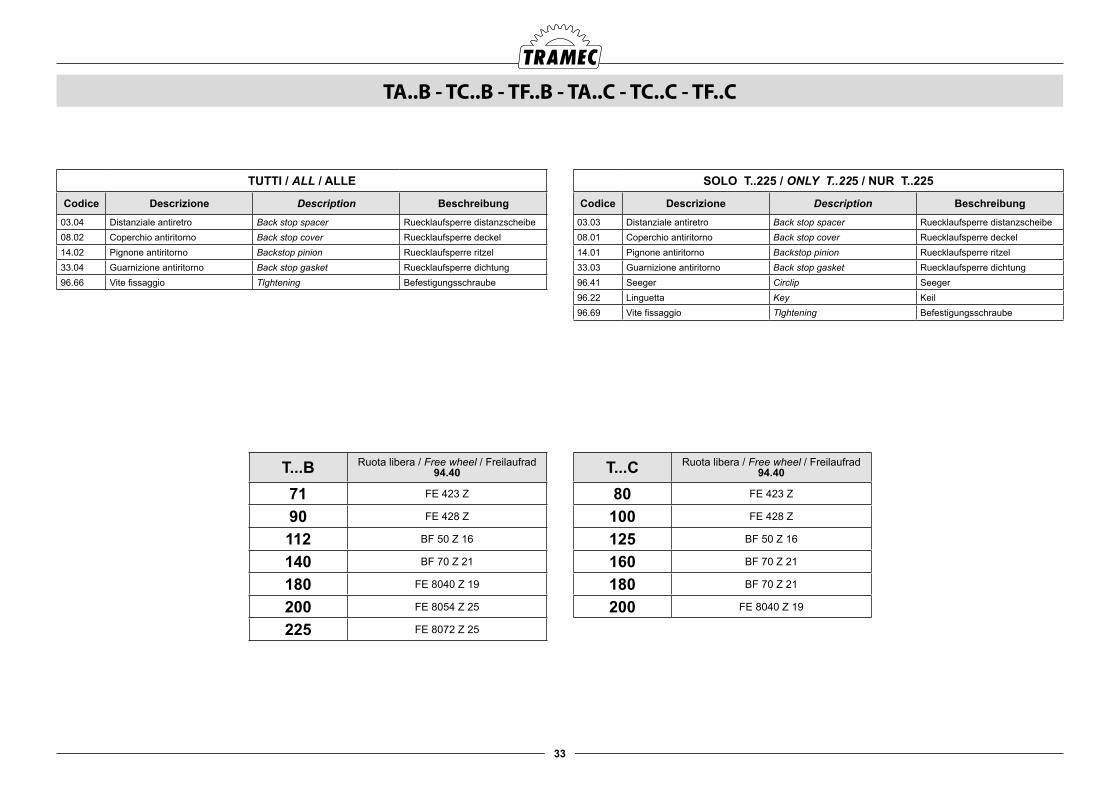
33
TUTTI / ALL / ALLE
Codice Descrizione Description Beschreibung03.04 Distanziale antiretro Back stop spacer Ruecklaufsperre distanzscheibe08.02 Coperchio antiritorno Back stop cover Ruecklaufsperre deckel14.02 Pignone antiritorno Backstop pinion Ruecklaufsperre ritzel33.04 Guarnizione antiritorno Back stop gasket Ruecklaufsperre dichtung 96.66 Vite fissaggio Tlghtening Befestigungsschraube
TA..B - TC..B - TF..B - TA..C - TC..C - TF..C
SOLO T..225 / ONLY T..225 / NUR T..225
Codice Descrizione Description Beschreibung03.03 Distanziale antiretro Back stop spacer Ruecklaufsperre distanzscheibe08.01 Coperchio antiritorno Back stop cover Ruecklaufsperre deckel14.01 Pignone antiritorno Backstop pinion Ruecklaufsperre ritzel 33.03 Guarnizione antiritorno Back stop gasket Ruecklaufsperre dichtung 96.41 Seeger Circlip Seeger96.22 Linguetta Key Keil96.69 Vite fissaggio Tlghtening Befestigungsschraube
T...B Ruota libera / Free wheel / Freilaufrad94.40
71 FE 423 Z
90 FE 428 Z
112 BF 50 Z 16
140 BF 70 Z 21
180 FE 8040 Z 19
200 FE 8054 Z 25
225 FE 8072 Z 25
T...C Ruota libera / Free wheel / Freilaufrad94.40
80 FE 423 Z
100 FE 428 Z
125 BF 50 Z 16
160 BF 70 Z 21
180 BF 70 Z 21
200 FE 8040 Z 19
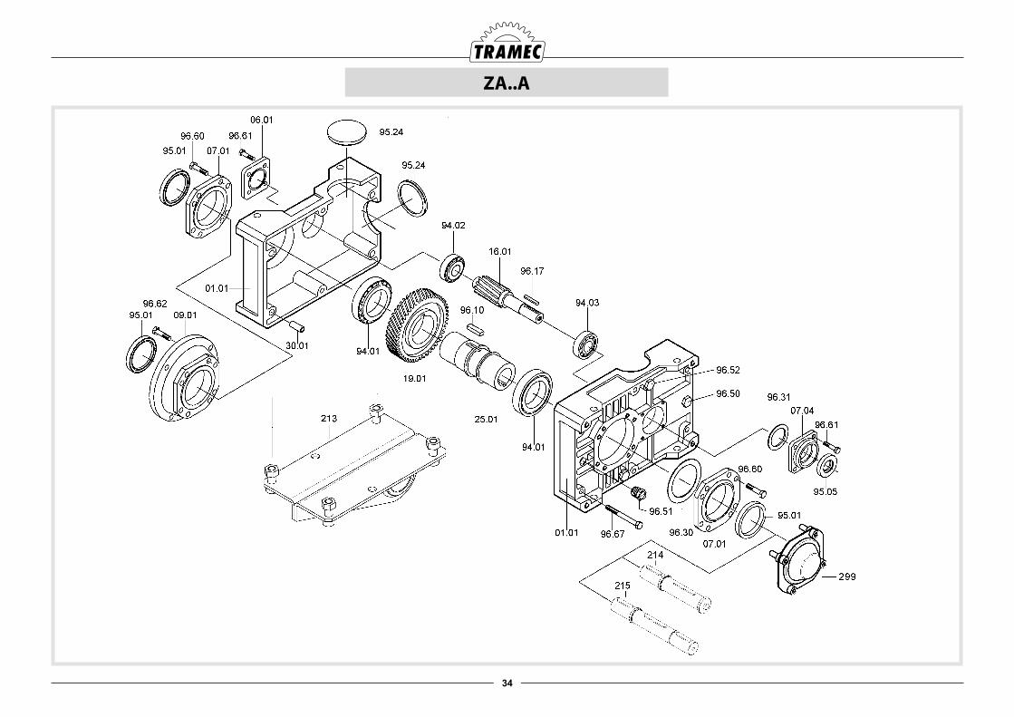
34
ZA..A
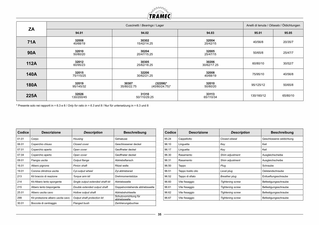
35
ZACuscinetti / Bearings / Lager Anelli di tenuta / Oilseals / Öldichtungen
94.01 94.02 94.03 95.01 95.05
71A 3200840/68/19
3030215/42/14.25
3200420/42/15 40/56/8 20/35/7
90A 3201050/80/20
3020420/47/15.25
3200525/47/15 50/65/8 25/47/7
112A 3201260/95/23
3030525/62/18.25
3020630/62/17.25 60/80/10 30/52/7
140A 3201575/115/25
3220630/62/21.25
3200840/68/19 75/95/10 40/56/8
180A 3201995/145/32
30307 35/80/22.75
(32208)*(40/80/24.75)*
3201050/80/20 95/125/12 50/65/8
225A 32026130/200/45
3131050/110/29.25
3311365/110/34 130/160/12 65/80/10
Codice Descrizione Description Beschreibung
01.01 Corpo Housing Gehaeuse
06.01 Coperchio chiuso Closed cover Geschlossener deckel
07.01 Coperchio aperto Open cover Geoffneter deckel
07.04 Coperchio aperto Open cover Geoffneter deckel
09.01 Flangia uscita Output flange Abtriebsflansch
16.01 Albero pignone Pinion shaft Ritzel welle
19.01 Corona cilindrica uscita Cyl.output wheel Zyl.abtriebsrad
213 Kit braccio di reazione Torque arm kit Drehmomentstütze
214 Kit Albero lento sporgente Single output extended shaft kit Abtriebswelle
215 Albero lento bisporgente Double extended output shaft Doppelvorstehende abtriebswelle
25.01 Albero uscita cavo Hollow output shaft Abtriebshohlwelle
299 Kit protezione albero uscita cavo Output shaft protection kit Schutzvorrichtung für abtriebswelle
30.01 Boccola di centraggio Flanged bush Zentrierungsbuchse
Codice Descrizione Description Beschreibung
95.24 Cappellotto Closed oilseal Geschlossene oeldichtung
96.10 Linguetta Key Keil
96.17 Linguetta Key Keil
96.30 Rasamento Shim adjustment Ausgleichscheibe
96.31 Rasamento Shim adjustment Ausgleichscheibe
96.50 Tappo Plug Schraube
96.51 Tappo livello olio Level plug Oelstandschraube
96.52 Tappo di sfiato Breather plug Entlueftungsschraube
96.60 Vite fissaggio TIghtening screw Befestigungsschraube
96.61 Vite fissaggio TIghtening screw Befestigungsschraube
96.62 Vite fissaggio TIghtening screw Befestigungsschraube
96.67 Vite fissaggio TIghtening screw Befestigungsschraube
* Presente solo nei rapporti in = 6.3 e 8 / Only for ratio in = 6.3 and 8 / Nur für untersetzung in = 6.3 und 8
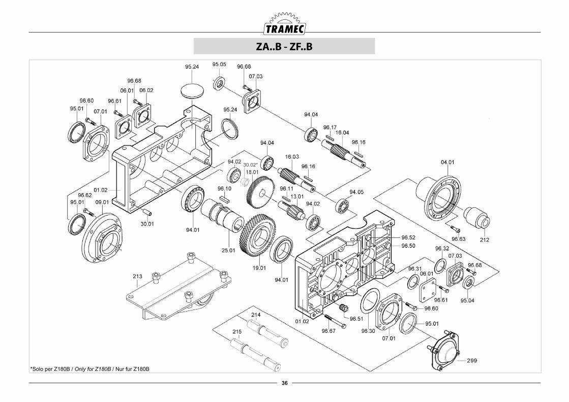
36
ZA..B - ZF..B
30.02*
*Solo per Z180B / Only for Z180B / Nur fur Z180B
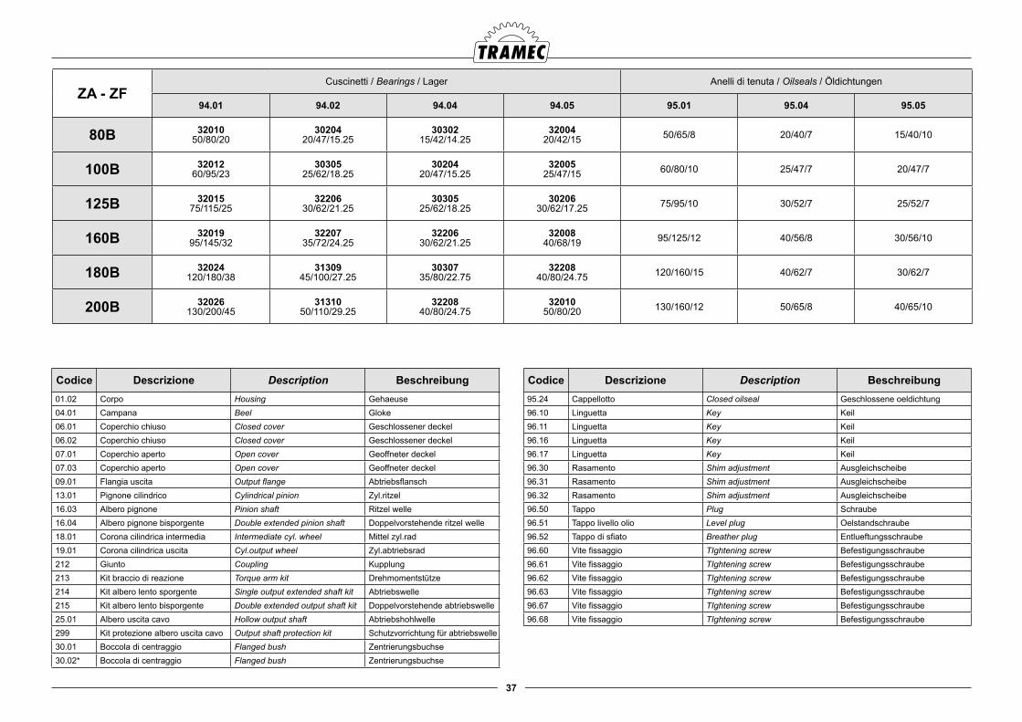
37
ZA - ZFCuscinetti / Bearings / Lager Anelli di tenuta / Oilseals / Öldichtungen
94.01 94.02 94.04 94.05 95.01 95.04 95.05
80B 3201050/80/20
3020420/47/15.25
3030215/42/14.25
3200420/42/15 50/65/8 20/40/7 15/40/10
100B 3201260/95/23
3030525/62/18.25
3020420/47/15.25
3200525/47/15 60/80/10 25/47/7 20/47/7
125B 3201575/115/25
3220630/62/21.25
3030525/62/18.25
3020630/62/17.25 75/95/10 30/52/7 25/52/7
160B 3201995/145/32
3220735/72/24.25
3220630/62/21.25
3200840/68/19 95/125/12 40/56/8 30/56/10
180B 32024120/180/38
3130945/100/27.25
3030735/80/22.75
3220840/80/24.75 120/160/15 40/62/7 30/62/7
200B 32026130/200/45
3131050/110/29.25
3220840/80/24.75
3201050/80/20 130/160/12 50/65/8 40/65/10
Codice Descrizione Description Beschreibung01.02 Corpo Housing Gehaeuse04.01 Campana Beel Gloke06.01 Coperchio chiuso Closed cover Geschlossener deckel06.02 Coperchio chiuso Closed cover Geschlossener deckel07.01 Coperchio aperto Open cover Geoffneter deckel07.03 Coperchio aperto Open cover Geoffneter deckel09.01 Flangia uscita Output flange Abtriebsflansch13.01 Pignone cilindrico Cylindrical pinion Zyl.ritzel 16.03 Albero pignone Pinion shaft Ritzel welle16.04 Albero pignone bisporgente Double extended pinion shaft Doppelvorstehende ritzel welle18.01 Corona cilindrica intermedia Intermediate cyl. wheel Mittel zyl.rad19.01 Corona cilindrica uscita Cyl.output wheel Zyl.abtriebsrad212 Giunto Coupling Kupplung213 Kit braccio di reazione Torque arm kit Drehmomentstütze214 Kit albero lento sporgente Single output extended shaft kit Abtriebswelle215 Kit albero lento bisporgente Double extended output shaft kit Doppelvorstehende abtriebswelle25.01 Albero uscita cavo Hollow output shaft Abtriebshohlwelle299 Kit protezione albero uscita cavo Output shaft protection kit Schutzvorrichtung für abtriebswelle30.01 Boccola di centraggio Flanged bush Zentrierungsbuchse30.02* Boccola di centraggio Flanged bush Zentrierungsbuchse
Codice Descrizione Description Beschreibung95.24 Cappellotto Closed oilseal Geschlossene oeldichtung96.10 Linguetta Key Keil96.11 Linguetta Key Keil96.16 Linguetta Key Keil96.17 Linguetta Key Keil96.30 Rasamento Shim adjustment Ausgleichscheibe96.31 Rasamento Shim adjustment Ausgleichscheibe96.32 Rasamento Shim adjustment Ausgleichscheibe96.50 Tappo Plug Schraube96.51 Tappo livello olio Level plug Oelstandschraube96.52 Tappo di sfiato Breather plug Entlueftungsschraube96.60 Vite fissaggio TIghtening screw Befestigungsschraube96.61 Vite fissaggio TIghtening screw Befestigungsschraube96.62 Vite fissaggio TIghtening screw Befestigungsschraube96.63 Vite fissaggio TIghtening screw Befestigungsschraube96.67 Vite fissaggio TIghtening screw Befestigungsschraube96.68 Vite fissaggio TIghtening screw Befestigungsschraube
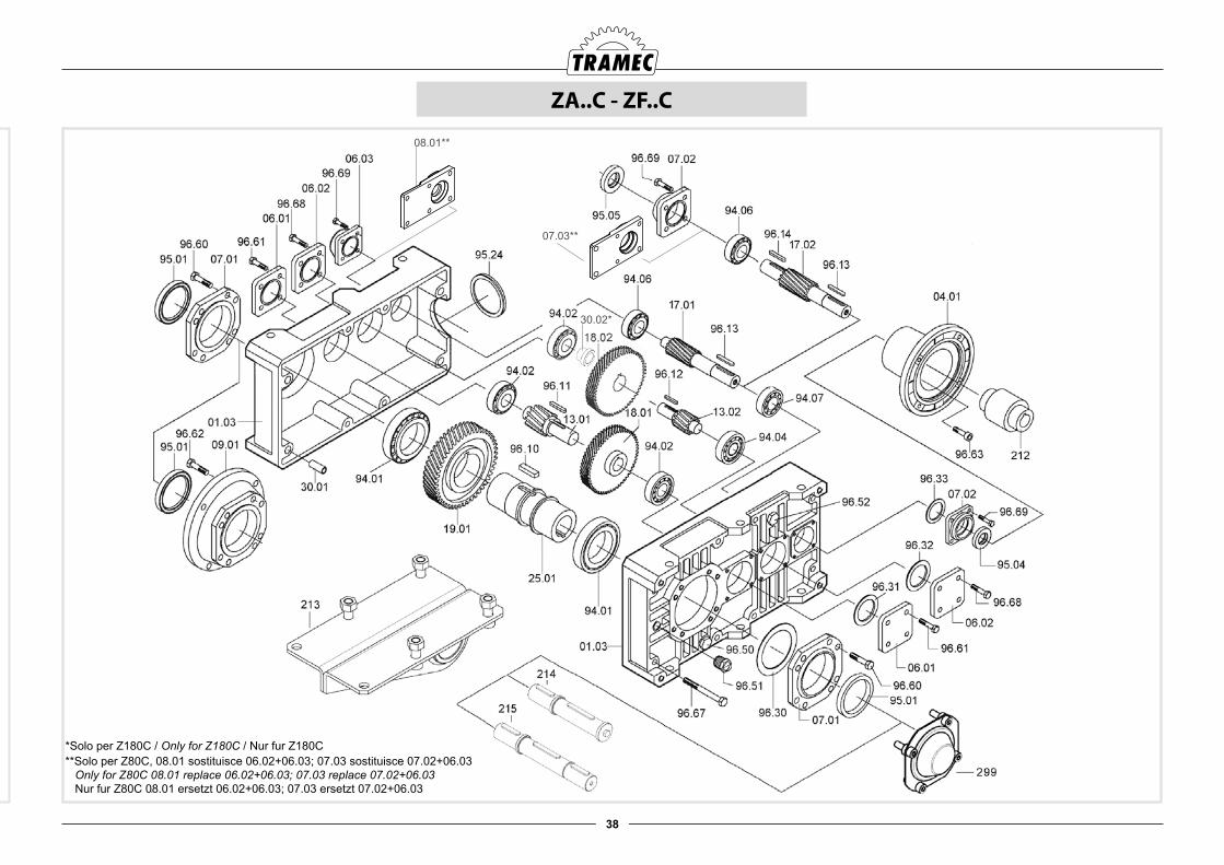
38
ZA..C - ZF..C
30.02*
08.01**
07.03**
*Solo per Z180C / Only for Z180C / Nur fur Z180C **Solo per Z80C, 08.01 sostituisce 06.02+06.03; 07.03 sostituisce 07.02+06.03 Only for Z80C 08.01 replace 06.02+06.03; 07.03 replace 07.02+06.03 Nur fur Z80C 08.01 ersetzt 06.02+06.03; 07.03 ersetzt 07.02+06.03
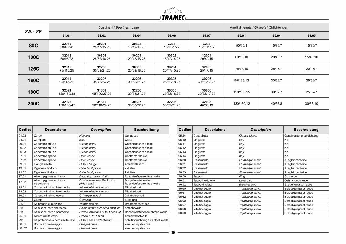
39
ZA - ZFCuscinetti / Bearings / Lager Anelli di tenuta / Oilseals / Öldichtungen
94.01 94.02 94.04 94.06 94.07 95.01 95.04 95.05
80C 3201050/80/20
3020420/47/15.25
3030215/42/14.25
320215/35/15.9
320215/35/15.9 50/65/8 15/30/7 15/30/7
100C 3201260/95/23
3030525/62/18.25
3020420/47/15.25
3030215/42/14.25
3200420/42/15 60/80/10 20/40/7 15/40/10
125C 3201575/115/25
3220630/62/21.25
3030525/62/18.25
3020420/47/15.25
3200525/47/15 75/95/10 25/47/7 20/47/7
160C 3201995/145/32
3220735/72/24.25
3220630/62/21.25
3030525/62/18.25
3020630/62/17.25 95/125/12 30/52/7 25/52/7
180C 32024120/180/38
3130945/100/27.25
3220630/62/21.25
3030525/62/18.25
3020630/62/17.25 120/160/15 30/52/7 25/52/7
200C 32026130/200/45
3131050/110/29.25
3030735/80/22.75
3220630/62/21.25
3200840/68/19 130/160/12 40/56/8 30/56/10
Codice Descrizione Description Beschreibung01.03 Corpo Housing Gehaeuse04.01 Campana Beel Gloke06.01 Coperchio chiuso Closed cover Geschlossener deckel06.02 Coperchio chiuso Closed cover Geschlossener deckel06.03 Coperchio chiuso Closed cover Geschlossener deckel07.01 Coperchio aperto Open cover Geoffneter deckel07.02 Coperchio aperto Open cover Geoffneter deckel09.01 Flangia uscita Output flange Abtriebsflansch13.01 Pignone cilindrico Cylindrical pinion Zyl.ritzel 13.02 Pignone cilindrico Cylindrical pinion Zyl.ritzel 17.01 Albero pignone antiretro Back stop pinion shaft Ruecklaufsperre ritzel welle
17.02 Albero pignone antiretro bisporgente
Double extended Back stoppinion shaft
DoppelvorstehendeRuecklaufsperre ritzel welle
18.01 Corona cilindrica intermedia Intermediate cyl. wheel Mittel zyl.rad18.02 Corona cilindrica intermedia Intermediate cyl. wheel Mittel zyl.rad19.01 Corona cilindrica uscita Cyl.output wheel Zyl.abtriebsrad212 Giunto Coupling Kupplung213 Kit braccio di reazione Torque arm kit Drehmomentstütze214 Kit albero lento sporgente Single output extended shaft kit Abtriebswelle215 Kit albero lento bisporgente Double extended output shaft kit Doppelvorstehende abtriebswelle25.01 Albero uscita cavo Hollow output shaft Abtriebshohlwelle299 Kit protezione albero uscita cavo Output shaft protection kit Schutzvorrichtung für abtriebswelle30.01 Boccola di centraggio Flanged bush Zentrierungsbuchse30.02* Boccola di centraggio Flanged bush Zentrierungsbuchse
Codice Descrizione Description Beschreibung95.24 Cappellotto Closed oilseal Geschlossene oeldichtung96.10 Linguetta Key Keil96.11 Linguetta Key Keil96.12 Linguetta Key Keil96.13 Linguetta Key Keil96.14 Linguetta Key Keil96.30 Rasamento Shim adjustment Ausgleichscheibe96.31 Rasamento Shim adjustment Ausgleichscheibe96.32 Rasamento Shim adjustment Ausgleichscheibe96.33 Rasamento Shim adjustment Ausgleichscheibe96.50 Tappo Plug Schraube96.51 Tappo livello olio Level plug Oelstandschraube96.52 Tappo di sfiato Breather plug Entlueftungsschraube96.60 Vite fissaggio TIghtening screw Befestigungsschraube96.61 Vite fissaggio TIghtening screw Befestigungsschraube96.62 Vite fissaggio TIghtening screw Befestigungsschraube96.63 Vite fissaggio TIghtening screw Befestigungsschraube96.67 Vite fissaggio TIghtening screw Befestigungsschraube96.68 Vite fissaggio TIghtening screw Befestigungsschraube96.69 Vite fissaggio TIghtening screw Befestigungsschraube
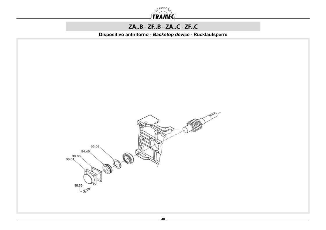
40
ZA..B - ZF..B - ZA..C - ZF..CDispositivo antiritorno - Backstop device - Rücklaufsperre
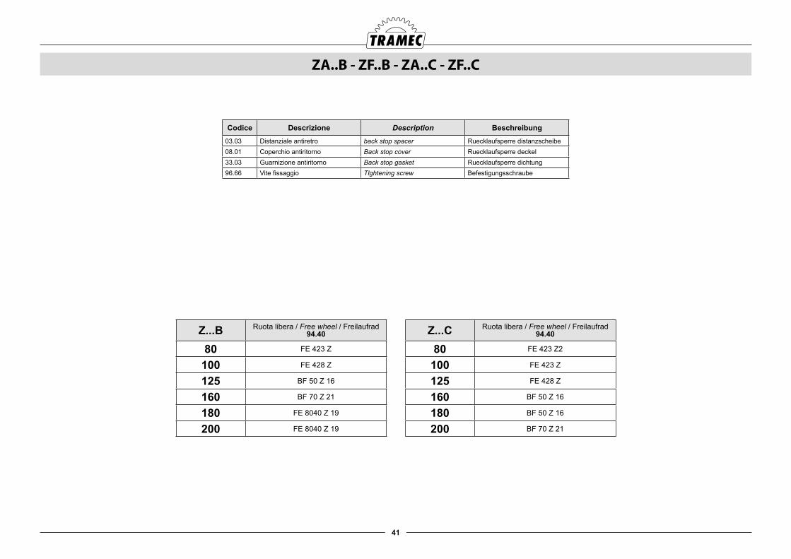
41
ZA..B - ZF..B - ZA..C - ZF..C
Codice Descrizione Description Beschreibung03.03 Distanziale antiretro back stop spacer Ruecklaufsperre distanzscheibe08.01 Coperchio antiritorno Back stop cover Ruecklaufsperre deckel33.03 Guarnizione antiritorno Back stop gasket Ruecklaufsperre dichtung 96.66 Vite fissaggio Tlghtening screw Befestigungsschraube
Z...B Ruota libera / Free wheel / Freilaufrad94.40
80 FE 423 Z
100 FE 428 Z
125 BF 50 Z 16
160 BF 70 Z 21
180 FE 8040 Z 19
200 FE 8040 Z 19
Z...C Ruota libera / Free wheel / Freilaufrad94.40
80 FE 423 Z2
100 FE 423 Z
125 FE 428 Z
160 BF 50 Z 16
180 BF 50 Z 16
200 BF 70 Z 21
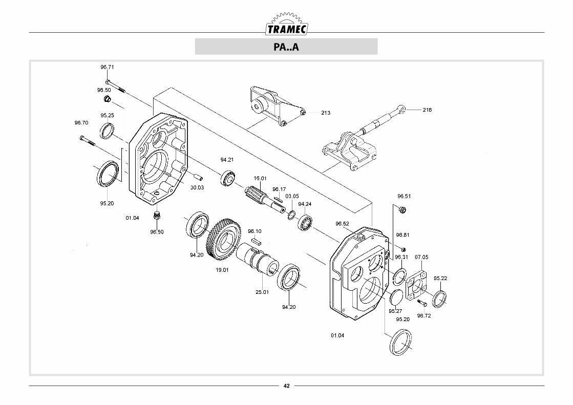
42
PA..A
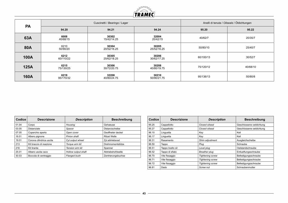
43
PACuscinetti / Bearings / Lager Anelli di tenuta / Oilseals / Öldichtungen
94.20 94.21 94.24 95.20 95.22
63A 600840/68/15
3030215/42/14.25
3200420/42/15 40/62/7 20/35/7
80A 621050/90/20
3030420/52/16.25
3020525/52/16.25 50/80/10 25/40/7
100A 621260/110/22
3030525/62/18.25
3020630/62/17.25 60/100/13 30/52/7
125A 621575/130/25
3030630/72/20.75
3020840/80/19.75 75/120/12 40/68/10
160A 621995/170/32
3220840/80/24.75
3021050/90/21.75 95/136/13 50/80/8
Codice Descrizione Description Beschreibung01.04 Corpo Housing Gehaeuse03.05 Distanziale Spacer Distanzscheibe07.05 Coperchio aperto Open cover Geoffneter deckel16.01 Albero pignone Pinion shaft Ritzel Welle19.01 Corona cilindrica uscita Cyl.output wheel Zyl.abtriebsrad213 Kit braccio di reazione Torque arm kit Drehmomentstütze216 Kit tirante Tension arm kit Spanner25.01 Albero uscita cavo Hollow output shaft Abtriebshohlwelle30.03 Boccola di centraggio Flanged bush Zentrierungsbuchse
Codice Descrizione Description Beschreibung95.25 Cappellotto Closed oilseal Geschlossene oeldichtung 95.27 Cappellotto Closed oilseal Geschlossene oeldichtung 96.10 Linguetta Key Keil96.17 Linguetta Key Keil96.31 Rasamento Shim adjustment Ausgleichscheibe96.50 Tappo Plug Schraube96.51 Tappo livello oil Level plug Oelstandschraube96.52 Tappo di sfiato Breather plug Entlueftungsschraube96.70 Vite fissaggio TIghtening screw Befestigungsschraube96.71 Vite fissaggio TIghtening screw Befestigungsschraube96.72 Vite fissaggio TIghtening screw Befestigungsschraube96.81 Dado Screw nut Schraubenmutter
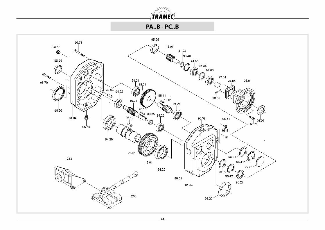
44
PA..B - PC..B
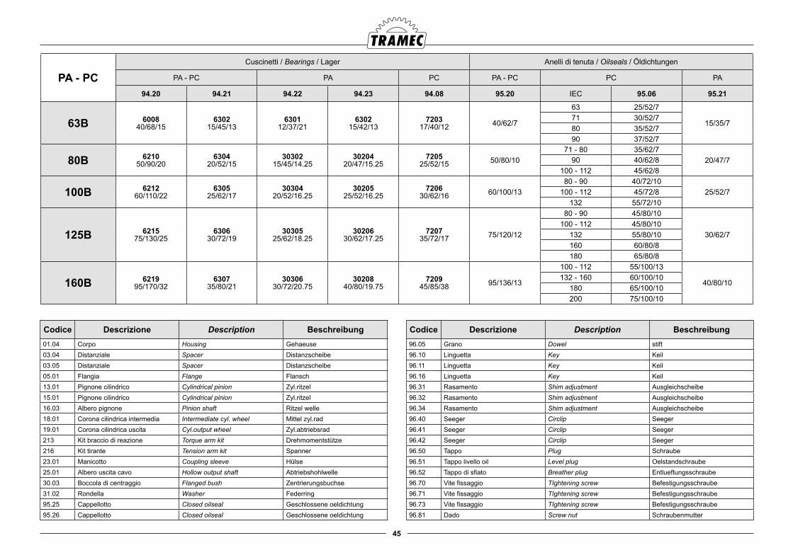
45
PA - PCCuscinetti / Bearings / Lager Anelli di tenuta / Oilseals / Öldichtungen
PA - PC PA PC PA - PC PC PA
94.20 94.21 94.22 94.23 94.08 95.20 IEC 95.06 95.21
63B 600840/68/15
630215/45/13
630112/37/21
630215/42/13
720317/40/12 40/62/7
63 25/52/7
15/35/771 30/52/780 35/52/790 37/52/7
80B 621050/90/20
630420/52/15
3030215/45/14.25
3020420/47/15.25
720525/52/15 50/80/10
71 - 80 35/62/720/47/790 40/62/8
100 - 112 45/62/8
100B 621260/110/22
630525/62/17
3030420/52/16.25
3020525/52/16.25
720630/62/16 60/100/13
80 - 90 40/72/1025/52/7100 - 112 45/72/8
132 55/72/10
125B 621575/130/25
630630/72/19
3030525/62/18.25
3020630/62/17.25
720735/72/17 75/120/12
80 - 90 45/80/10
30/62/7100 - 112 45/80/10
132 55/80/10160 60/80/8180 65/80/8
160B 621995/170/32
630735/80/21
3030630/72/20.75
3020840/80/19.75
720945/85/38 95/136/13
100 - 112 55/100/13
40/80/10132 - 160 60/100/10
180 65/100/10200 75/100/10
Codice Descrizione Description Beschreibung01.04 Corpo Housing Gehaeuse03.04 Distanziale Spacer Distanzscheibe03.05 Distanziale Spacer Distanzscheibe05.01 Flangia Flange Flansch13.01 Pignone cilindrico Cylindrical pinion Zyl.ritzel 15.01 Pignone cilindrico Cylindrical pinion Zyl.ritzel 16.03 Albero pignone Pinion shaft Ritzel welle18.01 Corona cilindrica intermedia Intermediate cyl. wheel Mittel zyl.rad19.01 Corona cilindrica uscita Cyl.output wheel Zyl.abtriebsrad213 Kit braccio di reazione Torque arm kit Drehmomentstütze216 Kit tirante Tension arm kit Spanner23.01 Manicotto Coupling sleeve Hülse25.01 Albero uscita cavo Hollow output shaft Abtriebshohlwelle30.03 Boccola di centraggio Flanged bush Zentrierungsbuchse31.02 Rondella Washer Federring95.25 Cappellotto Closed oilseal Geschlossene oeldichtung 95.26 Cappellotto Closed oilseal Geschlossene oeldichtung
Codice Descrizione Description Beschreibung96.05 Grano Dowel stift96.10 Linguetta Key Keil96.11 Linguetta Key Keil96.16 Linguetta Key Keil96.31 Rasamento Shim adjustment Ausgleichscheibe96.32 Rasamento Shim adjustment Ausgleichscheibe96.34 Rasamento Shim adjustment Ausgleichscheibe96.40 Seeger Circlip Seeger96.41 Seeger Circlip Seeger96.42 Seeger Circlip Seeger96.50 Tappo Plug Schraube96.51 Tappo livello oil Level plug Oelstandschraube96.52 Tappo di sfiato Breather plug Entlueftungsschraube96.70 Vite fissaggio TIghtening screw Befestigungsschraube96.71 Vite fissaggio TIghtening screw Befestigungsschraube96.73 Vite fissaggio TIghtening screw Befestigungsschraube96.81 Dado Screw nut Schraubenmutter
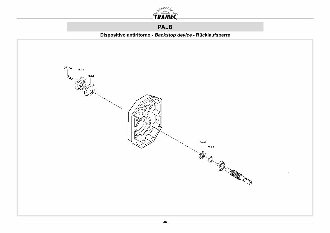
46
PA..BDispositivo antiritorno - Backstop device - Rücklaufsperre
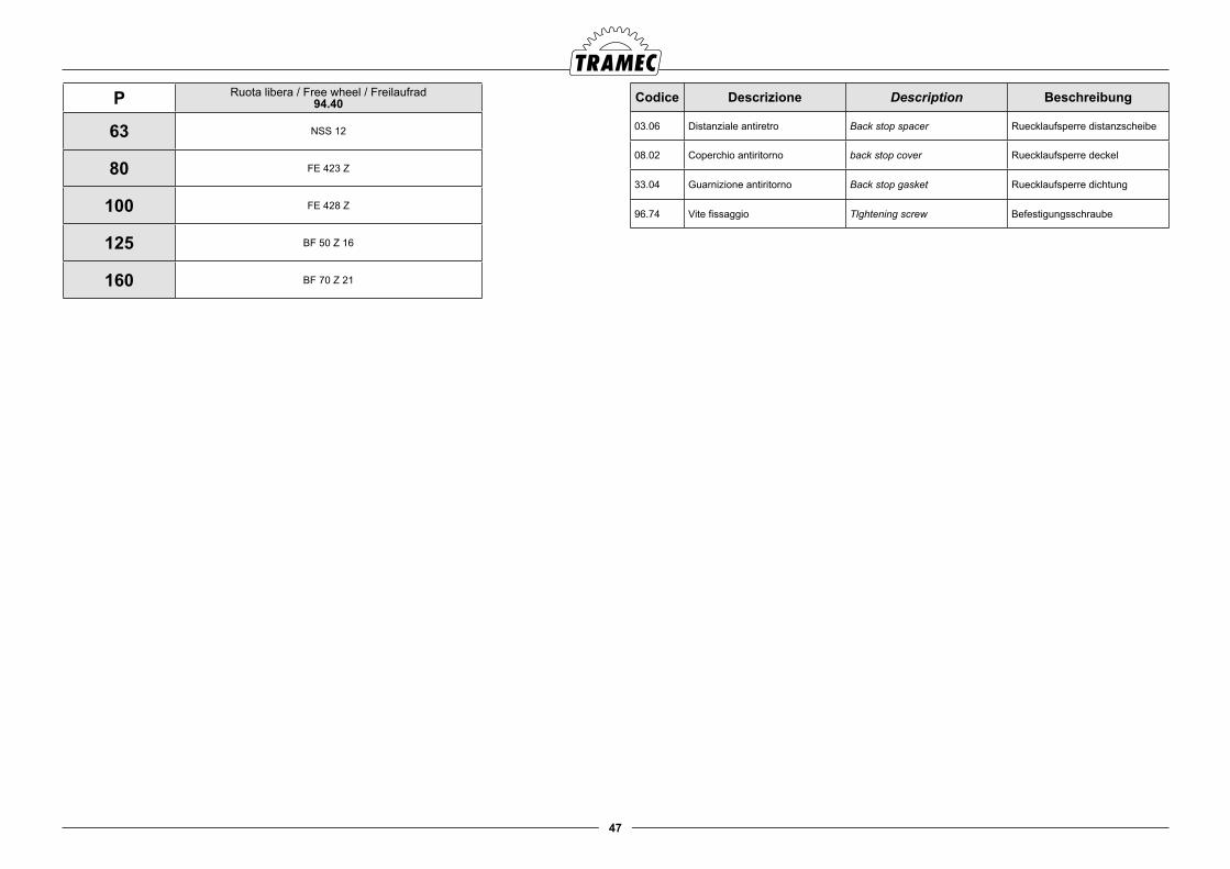
47
P Ruota libera / Free wheel / Freilaufrad 94.40
63 NSS 12
80 FE 423 Z
100 FE 428 Z
125 BF 50 Z 16
160 BF 70 Z 21
Codice Descrizione Description Beschreibung
03.06 Distanziale antiretro Back stop spacer Ruecklaufsperre distanzscheibe
08.02 Coperchio antiritorno back stop cover Ruecklaufsperre deckel
33.04 Guarnizione antiritorno Back stop gasket Ruecklaufsperre dichtung
96.74 Vite fissaggio Tlghtening screw Befestigungsschraube
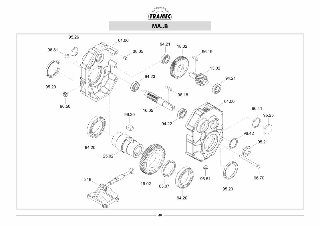
48
MA..B
96.7096.51
95.20
01.0694.21 18.02
94.21
13.02
96.19
94.23
96.18
16.05
94.22
30.05
96.50
94.20
96.20
25.02
19.02 03.07
94.20
96.81
95.26
01.06
95.20
96.42
95.21
96.4195.25
216
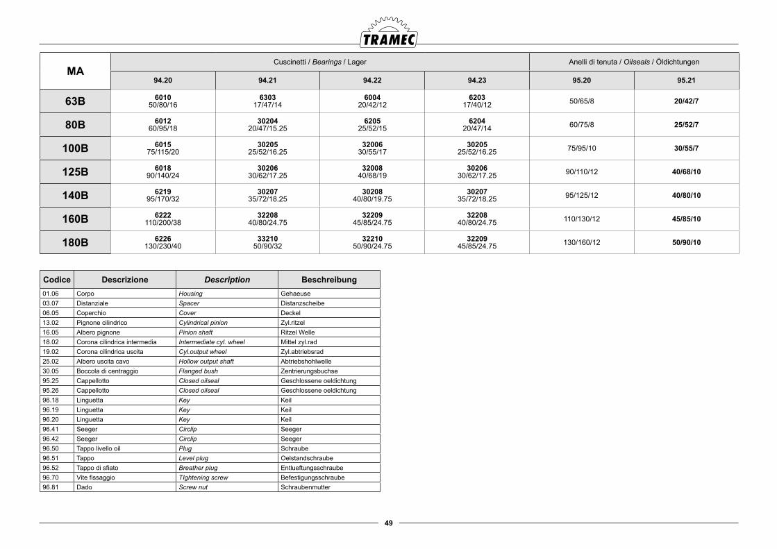
49
MACuscinetti / Bearings / Lager Anelli di tenuta / Oilseals / Öldichtungen
94.20 94.21 94.22 94.23 95.20 95.21
63B 601050/80/16
630317/47/14
600420/42/12
620317/40/12 50/65/8 20/42/7
80B 601260/95/18
3020420/47/15.25
620525/52/15
620420/47/14 60/75/8 25/52/7
100B 601575/115/20
3020525/52/16.25
3200630/55/17
3020525/52/16.25 75/95/10 30/55/7
125B 601890/140/24
3020630/62/17.25
3200840/68/19
3020630/62/17.25 90/110/12 40/68/10
140B 621995/170/32
3020735/72/18.25
3020840/80/19.75
3020735/72/18.25 95/125/12 40/80/10
160B 6222110/200/38
3220840/80/24.75
3220945/85/24.75
3220840/80/24.75 110/130/12 45/85/10
180B 6226130/230/40
3321050/90/32
3221050/90/24.75
3220945/85/24.75 130/160/12 50/90/10
Codice Descrizione Description Beschreibung01.06 Corpo Housing Gehaeuse03.07 Distanziale Spacer Distanzscheibe06.05 Coperchio Cover Deckel13.02 Pignone cilindrico Cylindrical pinion Zyl.ritzel 16.05 Albero pignone Pinion shaft Ritzel Welle18.02 Corona cilindrica intermedia Intermediate cyl. wheel Mittel zyl.rad19.02 Corona cilindrica uscita Cyl.output wheel Zyl.abtriebsrad25.02 Albero uscita cavo Hollow output shaft Abtriebshohlwelle30.05 Boccola di centraggio Flanged bush Zentrierungsbuchse95.25 Cappellotto Closed oilseal Geschlossene oeldichtung 95.26 Cappellotto Closed oilseal Geschlossene oeldichtung 96.18 Linguetta Key Keil96.19 Linguetta Key Keil96.20 Linguetta Key Keil96.41 Seeger Circlip Seeger96.42 Seeger Circlip Seeger96.50 Tappo livello oil Plug Schraube96.51 Tappo Level plug Oelstandschraube96.52 Tappo di sfiato Breather plug Entlueftungsschraube96.70 Vite fissaggio TIghtening screw Befestigungsschraube96.81 Dado Screw nut Schraubenmutter
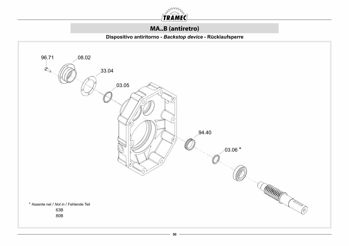
50
MA..B (antiretro)
94.40
03.06 *
03.05
33.04
08.0296.71
Dispositivo antiritorno - Backstop device - Rücklaufsperre
* Assente nel / Not in / Fehlende Teil63B80B
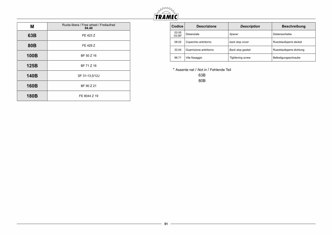
51
M Ruota libera / Free wheel / Freilaufrad 94.40
63B FE 423 Z
80B FE 428 Z
100B BF 50 Z 16
125B BF 71 Z 16
140B SF 31-13,5/12J
160B BF 90 Z 21
180B FE 8044 Z 19
Codice Descrizione Description Beschreibung03.0503.06* Distanziale Spacer Distanzscheibe
08.02 Coperchio antiritorno back stop cover Ruecklaufsperre deckel
33.04 Guarnizione antiritorno Back stop gasket Ruecklaufsperre dichtung
96.71 Vite fissaggio TIghtening screw Befestigungsschraube
* Assente nel / Not in / Fehlende Teil63B80B

52
RA - RC - RF (in = 1)
95.30
96.20
96.19
96.60
07.05
94.30
22.01
25.02
96.20
96.19
30.04
96.61
01.05
94.30
01.05
96.30
07.05
96.60
95.30
96.50
96.50
96.52
96.51
09.02
22.01
24.02
94.08
94.08
96.34
96.05
95.06
05.01 96.63
22.01
94.10
24.01
94.09
02.01
95.07
04.01
96.62
21229.01
96.19
06.04
96.20
28.01
96.02
96.21
96.18
96.02
96.21
96.41
23.01
96.60
96.64
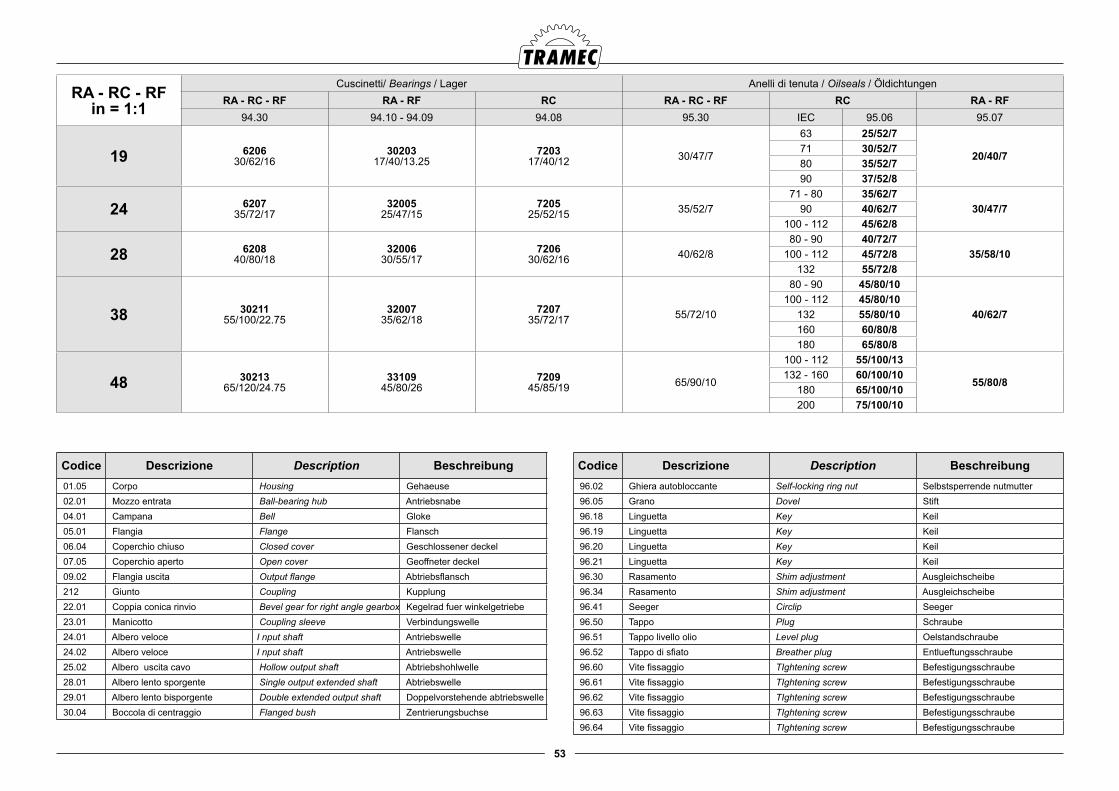
53
RA - RC - RFin = 1:1
Cuscinetti/ Bearings / Lager Anelli di tenuta / Oilseals / ÖldichtungenRA - RC - RF RA - RF RC RA - RC - RF RC RA - RF
94.30 94.10 - 94.09 94.08 95.30 IEC 95.06 95.07
19 620630/62/16
3020317/40/13.25
720317/40/12 30/47/7
63 25/52/7
20/40/771 30/52/780 35/52/790 37/52/8
24 620735/72/17
3200525/47/15
720525/52/15 35/52/7
71 - 80 35/62/730/47/790 40/62/7
100 - 112 45/62/8
28 620840/80/18
3200630/55/17
720630/62/16 40/62/8
80 - 90 40/72/735/58/10100 - 112 45/72/8
132 55/72/8
38 3021155/100/22.75
3200735/62/18
720735/72/17 55/72/10
80 - 90 45/80/10
40/62/7100 - 112 45/80/10
132 55/80/10160 60/80/8180 65/80/8
48 3021365/120/24.75
3310945/80/26
720945/85/19 65/90/10
100 - 112 55/100/13
55/80/8132 - 160 60/100/10
180 65/100/10200 75/100/10
Codice Descrizione Description Beschreibung 01.05 Corpo Housing Gehaeuse 02.01 Mozzo entrata Ball-bearing hub Antriebsnabe 04.01 Campana Bell Gloke 05.01 Flangia Flange Flansch 06.04 Coperchio chiuso Closed cover Geschlossener deckel 07.05 Coperchio aperto Open cover Geoffneter deckel 09.02 Flangia uscita Output flange Abtriebsflansch 212 Giunto Coupling Kupplung 22.01 Coppia conica rinvio Bevel gear for right angle gearbox Kegelrad fuer winkelgetriebe 23.01 Manicotto Coupling sleeve Verbindungswelle 24.01 Albero veloce I nput shaft Antriebswelle 24.02 Albero veloce I nput shaft Antriebswelle 25.02 Albero uscita cavo Hollow output shaft Abtriebshohlwelle 28.01 Albero lento sporgente Single output extended shaft Abtriebswelle 29.01 Albero lento bisporgente Double extended output shaft Doppelvorstehende abtriebswelle 30.04 Boccola di centraggio Flanged bush Zentrierungsbuchse
Codice Descrizione Description Beschreibung 96.02 Ghiera autobloccante Self-locking ring nut Selbstsperrende nutmutter 96.05 Grano Dovel Stift 96.18 Linguetta Key Keil 96.19 Linguetta Key Keil 96.20 Linguetta Key Keil 96.21 Linguetta Key Keil 96.30 Rasamento Shim adjustment Ausgleichscheibe 96.34 Rasamento Shim adjustment Ausgleichscheibe 96.41 Seeger Circlip Seeger 96.50 Tappo Plug Schraube 96.51 Tappo livello olio Level plug Oelstandschraube 96.52 Tappo di sfiato Breather plug Entlueftungsschraube 96.60 Vite fissaggio TIghtening screw Befestigungsschraube 96.61 Vite fissaggio TIghtening screw Befestigungsschraube 96.62 Vite fissaggio TIghtening screw Befestigungsschraube 96.63 Vite fissaggio TIghtening screw Befestigungsschraube 96.64 Vite fissaggio TIghtening screw Befestigungsschraube
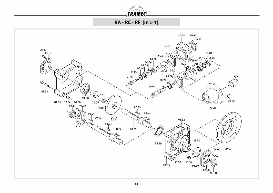
54
RA - RC - RF (in > 1)
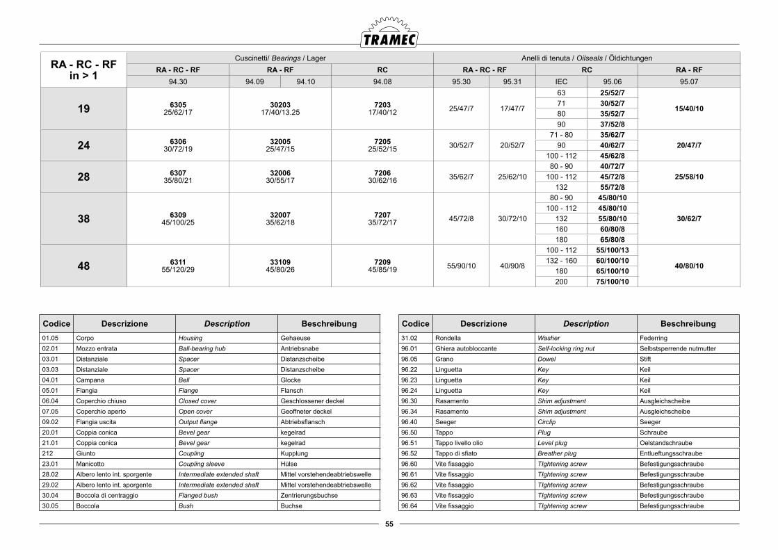
55
Codice Descrizione Description Beschreibung01.05 Corpo Housing Gehaeuse02.01 Mozzo entrata Ball-bearing hub Antriebsnabe 03.01 Distanziale Spacer Distanzscheibe03.03 Distanziale Spacer Distanzscheibe04.01 Campana Bell Glocke05.01 Flangia Flange Flansch06.04 Coperchio chiuso Closed cover Geschlossener deckel07.05 Coperchio aperto Open cover Geoffneter deckel09.02 Flangia uscita Output flange Abtriebsflansch20.01 Coppia conica Bevel gear kegelrad 21.01 Coppia conica Bevel gear kegelrad 212 Giunto Coupling Kupplung23.01 Manicotto Coupling sleeve Hülse28.02 Albero lento int. sporgente Intermediate extended shaft Mittel vorstehendeabtriebswelle29.02 Albero lento int. sporgente Intermediate extended shaft Mittel vorstehendeabtriebswelle30.04 Boccola di centraggio Flanged bush Zentrierungsbuchse30.05 Boccola Bush Buchse
Codice Descrizione Description Beschreibung31.02 Rondella Washer Federring96.01 Ghiera autobloccante Self-locking ring nut Selbstsperrende nutmutter96.05 Grano Dowel Stift96.22 Linguetta Key Keil96.23 Linguetta Key Keil96.24 Linguetta Key Keil96.30 Rasamento Shim adjustment Ausgleichscheibe96.34 Rasamento Shim adjustment Ausgleichscheibe96.40 Seeger Circlip Seeger96.50 Tappo Plug Schraube96.51 Tappo livello olio Level plug Oelstandschraube96.52 Tappo di sfiato Breather plug Entlueftungsschraube96.60 Vite fissaggio TIghtening screw Befestigungsschraube96.61 Vite fissaggio TIghtening screw Befestigungsschraube96.62 Vite fissaggio TIghtening screw Befestigungsschraube96.63 Vite fissaggio TIghtening screw Befestigungsschraube96.64 Vite fissaggio TIghtening screw Befestigungsschraube
RA - RC - RFin > 1
Cuscinetti/ Bearings / Lager Anelli di tenuta / Oilseals / ÖldichtungenRA - RC - RF RA - RF RC RA - RC - RF RC RA - RF
94.30 94.09 94.10 94.08 95.30 95.31 IEC 95.06 95.07
19 630525/62/17
3020317/40/13.25
720317/40/12 25/47/7 17/47/7
63 25/52/7
15/40/1071 30/52/780 35/52/790 37/52/8
24 630630/72/19
3200525/47/15
720525/52/15 30/52/7 20/52/7
71 - 80 35/62/720/47/790 40/62/7
100 - 112 45/62/8
28 630735/80/21
3200630/55/17
720630/62/16 35/62/7 25/62/10
80 - 90 40/72/725/58/10100 - 112 45/72/8
132 55/72/8
38 630945/100/25
3200735/62/18
720735/72/17 45/72/8 30/72/10
80 - 90 45/80/10
30/62/7100 - 112 45/80/10
132 55/80/10160 60/80/8180 65/80/8
48 631155/120/29
3310945/80/26
720945/85/19 55/90/10 40/90/8
100 - 112 55/100/13
40/80/10132 - 160 60/100/10
180 65/100/10200 75/100/10
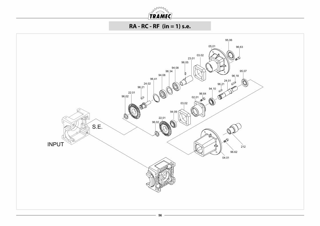
56
RA - RC - RF (in = 1) s.e.
INPUT
S.E.
22.01
24.02
94.08
94.08
96.34
96.05
95.06
05.01 96.63
22.01
94.10
24.01
94.09
02.01
95.07
04.01
96.62
212
96.02
96.21
96.18
96.02
96.21
96.41
23.01
03.02
03.02
96.64
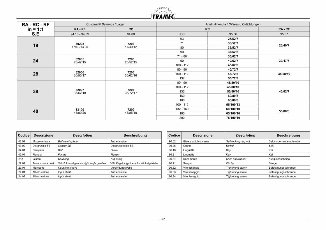
57
Codice Descrizione Description Beschreibung 02.01 Mozzo entrata Ball-bearing hub Antriebsnabe 03.02 Distanziale SE Spacer SE Distanzscheibe SE 04.01 Campana Bell Gloke 05.01 Flangia Flange Flansch 212 Giunto Coupling Kupplung 22.01 Terna conica rinvio Set of 3 bevel gear for right angle gearbox 3-St. Kegelradge triebe fur Winkelgetriebe 23.01 Manicotto Coupling sleeve Verbindungswelle 24.01 Albero veloce Input shaft Antriebswelle 24.02 Albero veloce Input shaft Antriebswelle
Codice Descrizione Description Beschreibung 96.02 Ghiera autobloccante Self-locking ring nut Selbstsperrende nutmutter 96.05 Grano Dowel Stift 96.18 Linguetta Key Keil 96.21 Linguetta Key Keil 96.34 Rasamento Shim adjustment Ausgleichscheibe 96.41 Seeger Circlip Seeger 96.62 Vite fissaggio TIghtening screw Befestigungsschraube 96.63 Vite fissaggio TIghtening screw Befestigungsschraube 96.64 Vite fissaggio TIghtening screw Befestigungsschraube
RA - RC - RFin = 1:1
S.E
Cuscinetti/ Bearings / Lager Anelli di tenuta / Oilseals / ÖldichtungenRA - RF RC RC RA - RF
94.10 - 94.09 94.08 IEC 95.06 95.07
19 3020317/40/13.25
720317/40/12
63 25/52/7
20/40/771 30/52/780 35/52/790 37/52/8
24 3200525/47/15
720525/52/15
71 - 80 35/62/730/47/790 40/62/7
100 - 112 45/62/8
28 3200630/55/17
720630/62/16
80 - 90 40/72/735/58/10100 - 112 45/72/8
132 55/72/8
38 3200735/62/18
720735/72/17
80 - 90 45/80/10
40/62/7100 - 112 45/80/10
132 55/80/10160 60/80/8180 65/80/8
48 3310945/80/26
720945/85/19
100 - 112 55/100/13
55/80/8132 - 160 60/100/10
180 65/100/10200 75/100/10
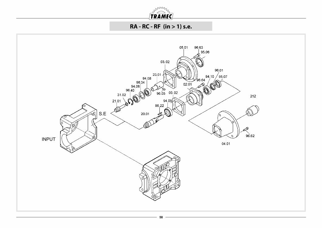
58
RA - RC - RF (in > 1) s.e.
S.E
INPUT
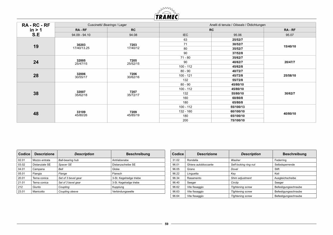
59
Codice Descrizione Description Beschreibung02.01 Mozzo entrata Ball-bearing hub Antriebsnabe 03.02 Distanziale SE Spacer SE Distanzscheibe SE04.01 Campana Bell Gloke05.01 Flangia Flange Flansch20.01 Terna conica Set of 3 bevel gear 3-St. Kegelradge triebe21.01 Terna conica Set of 3 bevel gear 3-St. Kegelradge triebe212 Giunto Coupling Kupplung23.01 Manicotto Coupling sleeve Verbindungswelle
Codice Descrizione Description Beschreibung 31.02 Rondella Washer Federring 96.01 Ghiera autobloccante Self-locking ring nut Selbstsperrende 96.05 Grano Dovel Stift 96.22 Linguetta Key Keil 96.34 Rasamento Shim adjustment Ausgleichscheibe 96.40 Seeger Circlip Seeger 96.62 Vite fissaggio TIghtening screw Befestigungsschraube 96.63 Vite fissaggio TIghtening screw Befestigungsschraube 96.64 Vite fissaggio TIghtening screw Befestigungsschraube
RA - RC - RFin > 1S.E
Cuscinetti/ Bearings / Lager Anelli di tenuta / Oilseals / ÖldichtungenRA - RF RC RC RA - RF
94.09 - 94.10 94.08 IEC 95.06 95.07
19 3020317/40/13.25
720317/40/12
63 25/52/7
15/40/1071 30/52/780 35/52/790 37/52/8
24 3200525/47/15
720525/52/15
71 - 80 35/62/720/47/790 40/62/7
100 - 112 45/62/8
28 3200630/55/17
720630/62/16
80 - 90 40/72/725/58/10100 - 121 45/72/8
132 55/72/8
38 3200735/62/18
720735/72/17
80 - 90 45/80/10
30/62/7100 - 112 45/80/10
132 55/80/10160 60/80/8180 65/80/8
48 3310945/80/26
720945/85/19
100 - 112 55/100/13
40/80/10132 - 160 60/100/10
180 65/100/10200 75/100/10
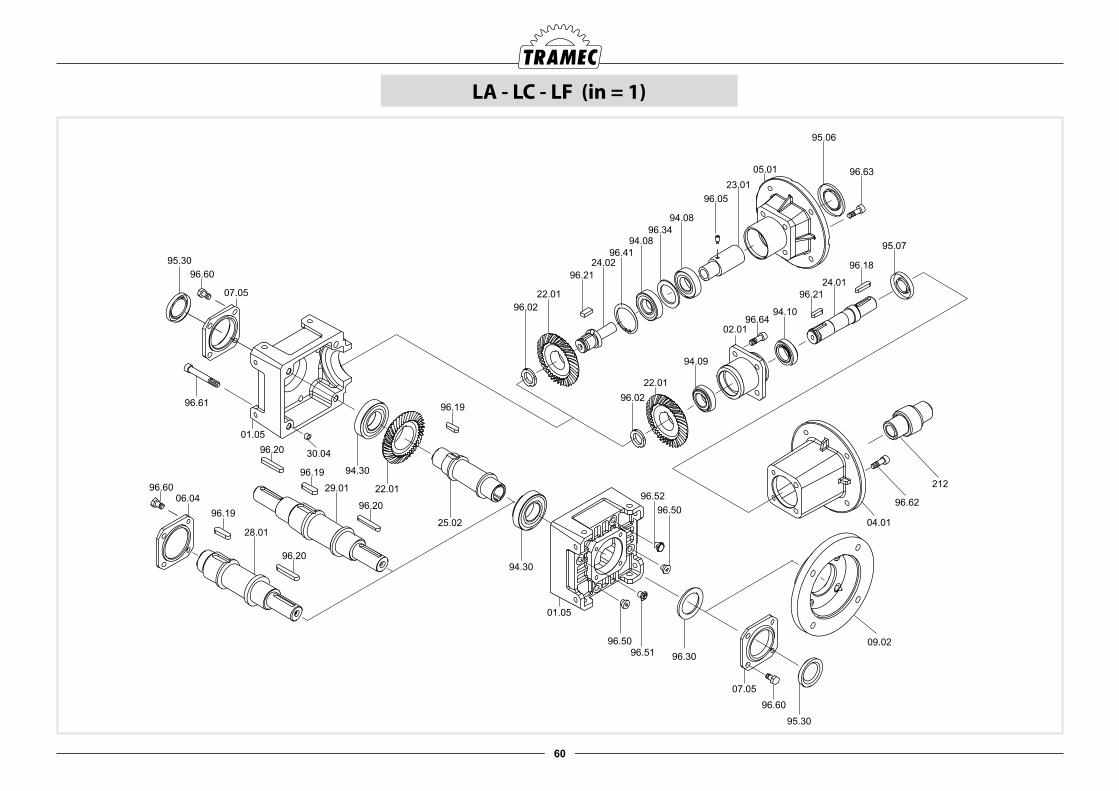
60
LA - LC - LF (in = 1)
95.30
96.20
96.19
96.60
07.05
94.30
22.01
25.02
96.20
96.19
30.04
96.61
01.05
94.30
01.05
96.30
07.05
96.60
95.30
96.50
96.50
96.52
96.51
09.02
22.01
24.02
94.08
94.08
96.34
96.05
95.06
05.01 96.63
22.01
94.10
24.01
94.09
02.01
95.07
04.01
96.62
21229.01
96.19
06.04
96.20
28.01
96.02
96.21
96.18
96.02
96.21
96.41
23.01
96.60
96.64
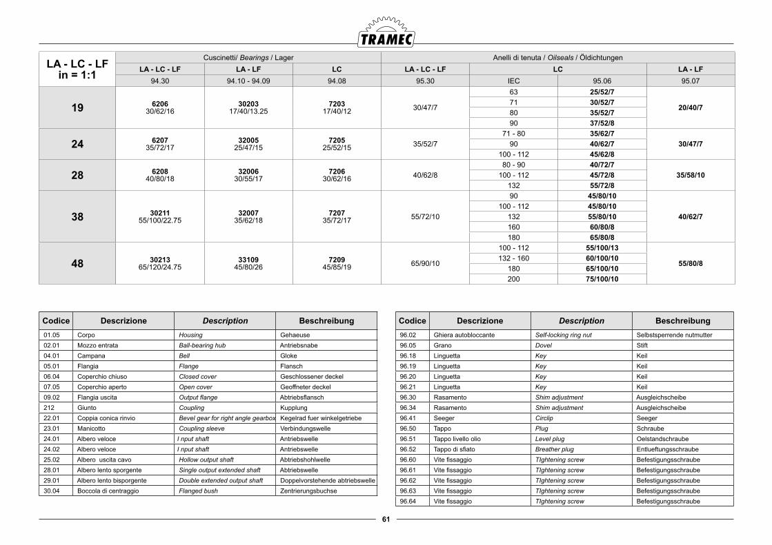
61
LA - LC - LFin = 1:1
Cuscinetti/ Bearings / Lager Anelli di tenuta / Oilseals / ÖldichtungenLA - LC - LF LA - LF LC LA - LC - LF LC LA - LF
94.30 94.10 - 94.09 94.08 95.30 IEC 95.06 95.07
19 620630/62/16
3020317/40/13.25
720317/40/12 30/47/7
63 25/52/7
20/40/771 30/52/780 35/52/790 37/52/8
24 620735/72/17
3200525/47/15
720525/52/15 35/52/7
71 - 80 35/62/730/47/790 40/62/7
100 - 112 45/62/8
28 620840/80/18
3200630/55/17
720630/62/16 40/62/8
80 - 90 40/72/735/58/10100 - 112 45/72/8
132 55/72/8
38 3021155/100/22.75
3200735/62/18
720735/72/17 55/72/10
90 45/80/10
40/62/7100 - 112 45/80/10
132 55/80/10160 60/80/8180 65/80/8
48 3021365/120/24.75
3310945/80/26
720945/85/19 65/90/10
100 - 112 55/100/13
55/80/8132 - 160 60/100/10
180 65/100/10200 75/100/10
Codice Descrizione Description Beschreibung 01.05 Corpo Housing Gehaeuse 02.01 Mozzo entrata Ball-bearing hub Antriebsnabe 04.01 Campana Bell Gloke 05.01 Flangia Flange Flansch 06.04 Coperchio chiuso Closed cover Geschlossener deckel 07.05 Coperchio aperto Open cover Geoffneter deckel 09.02 Flangia uscita Output flange Abtriebsflansch 212 Giunto Coupling Kupplung 22.01 Coppia conica rinvio Bevel gear for right angle gearbox Kegelrad fuer winkelgetriebe 23.01 Manicotto Coupling sleeve Verbindungswelle 24.01 Albero veloce I nput shaft Antriebswelle 24.02 Albero veloce I nput shaft Antriebswelle 25.02 Albero uscita cavo Hollow output shaft Abtriebshohlwelle 28.01 Albero lento sporgente Single output extended shaft Abtriebswelle 29.01 Albero lento bisporgente Double extended output shaft Doppelvorstehende abtriebswelle 30.04 Boccola di centraggio Flanged bush Zentrierungsbuchse
Codice Descrizione Description Beschreibung 96.02 Ghiera autobloccante Self-locking ring nut Selbstsperrende nutmutter 96.05 Grano Dovel Stift 96.18 Linguetta Key Keil 96.19 Linguetta Key Keil 96.20 Linguetta Key Keil 96.21 Linguetta Key Keil 96.30 Rasamento Shim adjustment Ausgleichscheibe 96.34 Rasamento Shim adjustment Ausgleichscheibe 96.41 Seeger Circlip Seeger 96.50 Tappo Plug Schraube 96.51 Tappo livello olio Level plug Oelstandschraube 96.52 Tappo di sfiato Breather plug Entlueftungsschraube 96.60 Vite fissaggio TIghtening screw Befestigungsschraube 96.61 Vite fissaggio TIghtening screw Befestigungsschraube 96.62 Vite fissaggio TIghtening screw Befestigungsschraube 96.63 Vite fissaggio TIghtening screw Befestigungsschraube 96.64 Vite fissaggio TIghtening screw Befestigungsschraube
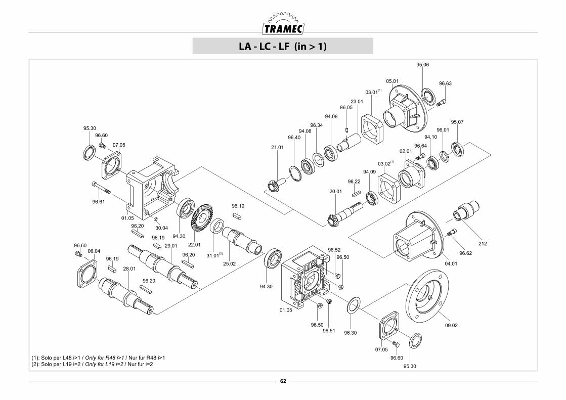
62
LA - LC - LF (in > 1)
95.30
96.20
96.19
96.60
07.05
94.30
22.01
25.02
96.20
96.19
30.04
96.61
01.05
94.30
01.05
96.30
07.0596.60
95.30
96.50
96.5096.52
96.5109.02
21.01
96.4094.08
94.08
96.34
96.05
95.06
03.01(1)
31.01(2)
03.02(1)
05.01 96.63
20.01
96.22
94.09
02.01
94.1096.01
95.07
04.01
96.62
21229.01
23.01
96.1906.04
28.01
96.20
96.60
96.64
(1): Solo per L48 i>1 / Only for R48 i>1 / Nur fur R48 i>1(2): Solo per L19 i=2 / Only for L19 i=2 / Nur fur i=2
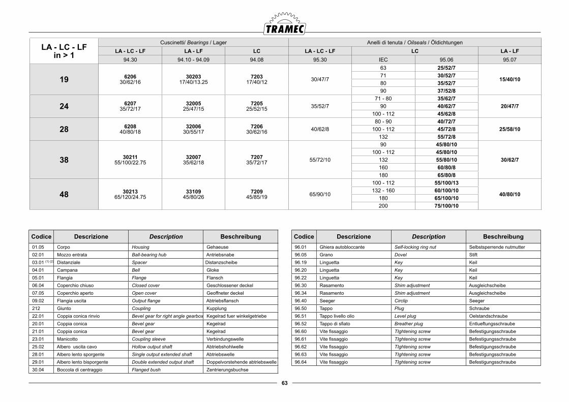
63
LA - LC - LFin > 1
Cuscinetti/ Bearings / Lager Anelli di tenuta / Oilseals / ÖldichtungenLA - LC - LF LA - LF LC LA - LC - LF LC LA - LF
94.30 94.10 - 94.09 94.08 95.30 IEC 95.06 95.07
19 620630/62/16
3020317/40/13.25
720317/40/12 30/47/7
63 25/52/7
15/40/1071 30/52/780 35/52/790 37/52/8
24 620735/72/17
3200525/47/15
720525/52/15 35/52/7
71 - 80 35/62/720/47/790 40/62/7
100 - 112 45/62/8
28 620840/80/18
3200630/55/17
720630/62/16 40/62/8
80 - 90 40/72/725/58/10100 - 112 45/72/8
132 55/72/8
38 3021155/100/22.75
3200735/62/18
720735/72/17 55/72/10
90 45/80/10
30/62/7100 - 112 45/80/10
132 55/80/10160 60/80/8180 65/80/8
48 3021365/120/24.75
3310945/80/26
720945/85/19 65/90/10
100 - 112 55/100/13
40/80/10132 - 160 60/100/10
180 65/100/10200 75/100/10
Codice Descrizione Description Beschreibung 01.05 Corpo Housing Gehaeuse 02.01 Mozzo entrata Ball-bearing hub Antriebsnabe 03.01 (1) (2) Distanziale Spacer Distanzscheibe 04.01 Campana Bell Gloke 05.01 Flangia Flange Flansch 06.04 Coperchio chiuso Closed cover Geschlossener deckel 07.05 Coperchio aperto Open cover Geoffneter deckel 09.02 Flangia uscita Output flange Abtriebsflansch 212 Giunto Coupling Kupplung 22.01 Coppia conica rinvio Bevel gear for right angle gearbox Kegelrad fuer winkelgetriebe 20.01 Coppia conica Bevel gear Kegelrad 21.01 Coppia conica Bevel gear Kegelrad 23.01 Manicotto Coupling sleeve Verbindungswelle 25.02 Albero uscita cavo Hollow output shaft Abtriebshohlwelle 28.01 Albero lento sporgente Single output extended shaft Abtriebswelle 29.01 Albero lento bisporgente Double extended output shaft Doppelvorstehende abtriebswelle 30.04 Boccola di centraggio Flanged bush Zentrierungsbuchse
Codice Descrizione Description Beschreibung 96.01 Ghiera autobloccante Self-locking ring nut Selbstsperrende nutmutter 96.05 Grano Dovel Stift 96.19 Linguetta Key Keil 96.20 Linguetta Key Keil 96.22 Linguetta Key Keil 96.30 Rasamento Shim adjustment Ausgleichscheibe 96.34 Rasamento Shim adjustment Ausgleichscheibe 96.40 Seeger Circlip Seeger 96.50 Tappo Plug Schraube 96.51 Tappo livello olio Level plug Oelstandschraube 96.52 Tappo di sfiato Breather plug Entlueftungsschraube 96.60 Vite fissaggio TIghtening screw Befestigungsschraube 96.61 Vite fissaggio TIghtening screw Befestigungsschraube 96.62 Vite fissaggio TIghtening screw Befestigungsschraube 96.63 Vite fissaggio TIghtening screw Befestigungsschraube 96.64 Vite fissaggio TIghtening screw Befestigungsschraube

64
LA - LC - LF (in = 1) s.e.
INPUT
S.E.
22.01
24.02
94.08
94.08
96.34
96.05
95.06
05.01 96.63
22.01
94.10
24.01
94.09
02.01
95.07
04.01
96.62
212
96.02
96.21
96.18
96.02
96.21
96.41
23.01
03.02
03.02
96.64
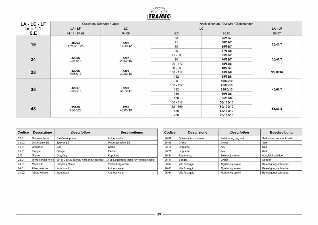
65
LA - LC - LFin = 1:1
S.E
Cuscinetti/ Bearings / Lager Anelli di tenuta / Oilseals / ÖldichtungenLA - LF LC LC LA - LF
94.10 - 94.09 94.08 IEC 95.06 95.07
19 3020317/40/13.25
720317/40/12
63 25/52/7
20/40/771 30/52/780 35/52/790 37/52/8
24 3200525/47/15
720525/52/15
71 - 80 35/62/730/47/790 40/62/7
100 - 112 45/62/8
28 3200630/55/17
720630/62/16
80 - 90 40/72/735/58/10100 - 112 45/72/8
132 55/72/8
38 3200735/62/18
720735/72/17
90 45/80/10
40/62/7100 - 112 45/80/10
132 55/80/10160 60/80/8180 65/80/8
48 3310945/80/26
720945/85/19
100 - 112 55/100/13
55/80/8132 - 160 60/100/10
180 65/100/10200 75/100/10
Codice Descrizione Description Beschreibung 02.01 Mozzo entrata Ball-bearing hub Antriebsnabe 03.02 Distanziale SE Spacer SE Distanzscheibe SE 04.01 Campana Bell Gloke 05.01 Flangia Flange Flansch 212 Giunto Coupling Kupplung 22.01 Terna conica rinvio Set of 3 bevel gear for right angle gearbox 3-St. Kegelradge triebe fur Winkelgetriebe 23.01 Manicotto Coupling sleeve Verbindungswelle 24.01 Albero veloce Input shaft Antriebswelle 24.02 Albero veloce Input shaft Antriebswelle
Codice Descrizione Description Beschreibung 96.02 Ghiera autobloccante Self-locking ring nut Selbstsperrende nutmutter 96.05 Grano Dowel Stift 96.18 Linguetta Key Keil 96.21 Linguetta Key Keil 96.34 Rasamento Shim adjustment Ausgleichscheibe 96.41 Seeger Circlip Seeger 96.62 Vite fissaggio TIghtening screw Befestigungsschraube 96.63 Vite fissaggio TIghtening screw Befestigungsschraube 96.64 Vite fissaggio TIghtening screw Befestigungsschraube
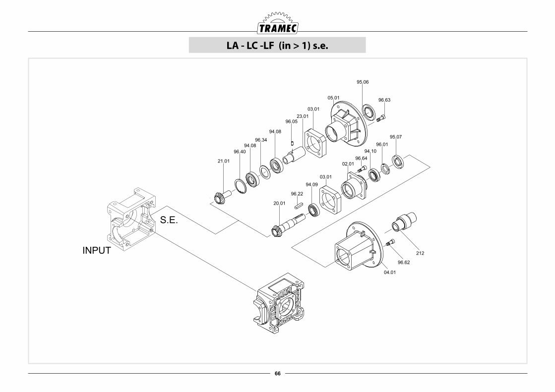
66
LA - LC -LF (in > 1) s.e.
21.01
96.40
94.08
94.08
96.34
96.05
95.06
03.01
03.01
05.0196.63
20.01
96.22
94.09
02.01
94.10
96.01
95.07
04.01
96.62
212
23.01
INPUT
S.E.
96.64
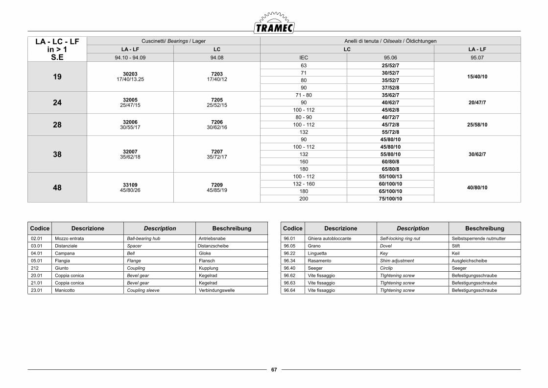
67
LA - LC - LFin > 1S.E
Cuscinetti/ Bearings / Lager Anelli di tenuta / Oilseals / ÖldichtungenLA - LF LC LC LA - LF
94.10 - 94.09 94.08 IEC 95.06 95.07
19 3020317/40/13.25
720317/40/12
63 25/52/7
15/40/1071 30/52/780 35/52/790 37/52/8
24 3200525/47/15
720525/52/15
71 - 80 35/62/720/47/790 40/62/7
100 - 112 45/62/8
28 3200630/55/17
720630/62/16
80 - 90 40/72/725/58/10100 - 112 45/72/8
132 55/72/8
38 3200735/62/18
720735/72/17
90 45/80/10
30/62/7100 - 112 45/80/10
132 55/80/10160 60/80/8180 65/80/8
48 3310945/80/26
720945/85/19
100 - 112 55/100/13
40/80/10132 - 160 60/100/10
180 65/100/10200 75/100/10
Codice Descrizione Description Beschreibung 02.01 Mozzo entrata Ball-bearing hub Antriebsnabe 03.01 Distanziale Spacer Distanzscheibe 04.01 Campana Bell Gloke 05.01 Flangia Flange Flansch 212 Giunto Coupling Kupplung 20.01 Coppia conica Bevel gear Kegelrad 21.01 Coppia conica Bevel gear Kegelrad 23.01 Manicotto Coupling sleeve Verbindungswelle
Codice Descrizione Description Beschreibung 96.01 Ghiera autobloccante Self-locking ring nut Selbstsperrende nutmutter 96.05 Grano Dovel Stift 96.22 Linguetta Key Keil 96.34 Rasamento Shim adjustment Ausgleichscheibe 96.40 Seeger Circlip Seeger 96.62 Vite fissaggio TIghtening screw Befestigungsschraube 96.63 Vite fissaggio TIghtening screw Befestigungsschraube 96.64 Vite fissaggio TIghtening screw Befestigungsschraube
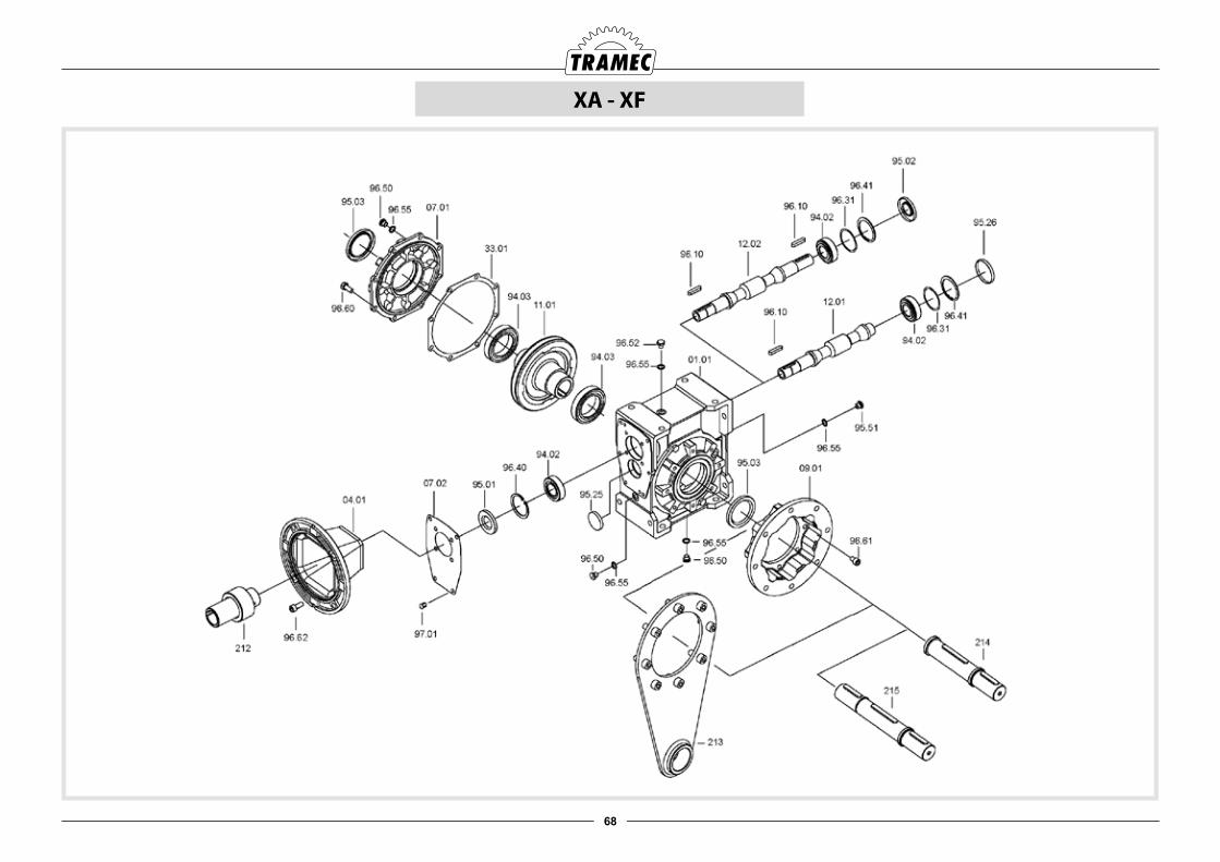
68
XA - XF
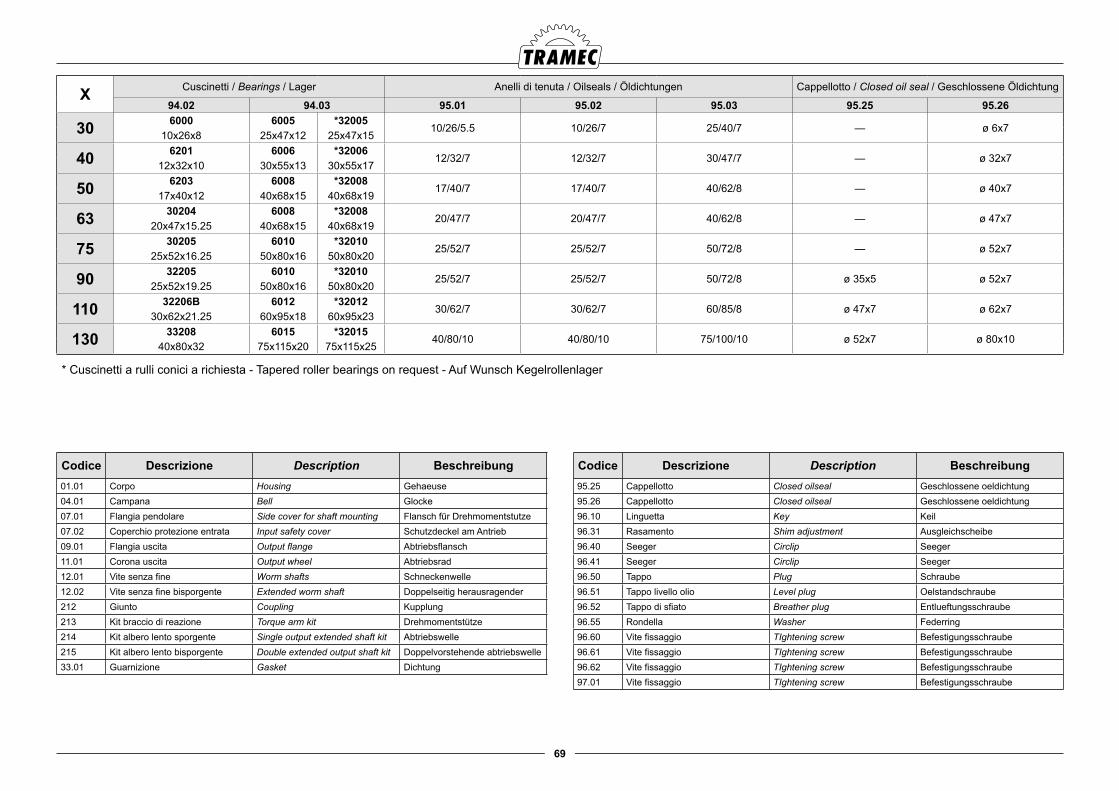
69
Codice Descrizione Description Beschreibung01.01 Corpo Housing Gehaeuse04.01 Campana Bell Glocke07.01 Flangia pendolare Side cover for shaft mounting Flansch für Drehmomentstutze07.02 Coperchio protezione entrata Input safety cover Schutzdeckel am Antrieb09.01 Flangia uscita Output flange Abtriebsflansch11.01 Corona uscita Output wheel Abtriebsrad12.01 Vite senza fine Worm shafts Schneckenwelle12.02 Vite senza fine bisporgente Extended worm shaft Doppelseitig herausragender212 Giunto Coupling Kupplung213 Kit braccio di reazione Torque arm kit Drehmomentstütze214 Kit albero lento sporgente Single output extended shaft kit Abtriebswelle215 Kit albero lento bisporgente Double extended output shaft kit Doppelvorstehende abtriebswelle33.01 Guarnizione Gasket Dichtung
Codice Descrizione Description Beschreibung95.25 Cappellotto Closed oilseal Geschlossene oeldichtung 95.26 Cappellotto Closed oilseal Geschlossene oeldichtung 96.10 Linguetta Key Keil96.31 Rasamento Shim adjustment Ausgleichscheibe96.40 Seeger Circlip Seeger96.41 Seeger Circlip Seeger96.50 Tappo Plug Schraube96.51 Tappo livello olio Level plug Oelstandschraube96.52 Tappo di sfiato Breather plug Entlueftungsschraube96.55 Rondella Washer Federring96.60 Vite fissaggio TIghtening screw Befestigungsschraube96.61 Vite fissaggio TIghtening screw Befestigungsschraube96.62 Vite fissaggio TIghtening screw Befestigungsschraube97.01 Vite fissaggio TIghtening screw Befestigungsschraube
X Cuscinetti / Bearings / Lager Anelli di tenuta / Oilseals / Öldichtungen Cappellotto / Closed oil seal / Geschlossene Öldichtung
94.02 94.03 95.01 95.02 95.03 95.25 95.26
30 6000 6005 *3200510/26/5.5 10/26/7 25/40/7 — ø 6x7
10x26x8 25x47x12 25x47x15
40 6201 6006 *3200612/32/7 12/32/7 30/47/7 — ø 32x7
12x32x10 30x55x13 30x55x17
50 6203 6008 *3200817/40/7 17/40/7 40/62/8 — ø 40x7
17x40x12 40x68x15 40x68x19
63 30204 6008 *3200820/47/7 20/47/7 40/62/8 — ø 47x7
20x47x15.25 40x68x15 40x68x19
75 30205 6010 *3201025/52/7 25/52/7 50/72/8 — ø 52x7
25x52x16.25 50x80x16 50x80x20
90 32205 6010 *3201025/52/7 25/52/7 50/72/8 ø 35x5 ø 52x7
25x52x19.25 50x80x16 50x80x20
110 32206B 6012 *3201230/62/7 30/62/7 60/85/8 ø 47x7 ø 62x7
30x62x21.25 60x95x18 60x95x23
130 33208 6015 *3201540/80/10 40/80/10 75/100/10 ø 52x7 ø 80x10
40x80x32 75x115x20 75x115x25
* Cuscinetti a rulli conici a richiesta - Tapered roller bearings on request - Auf Wunsch Kegelrollenlager
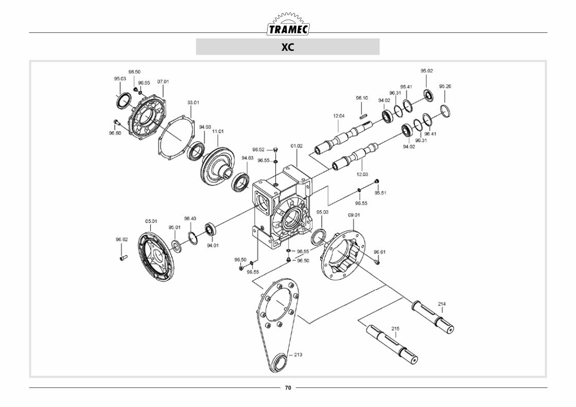
70
XC
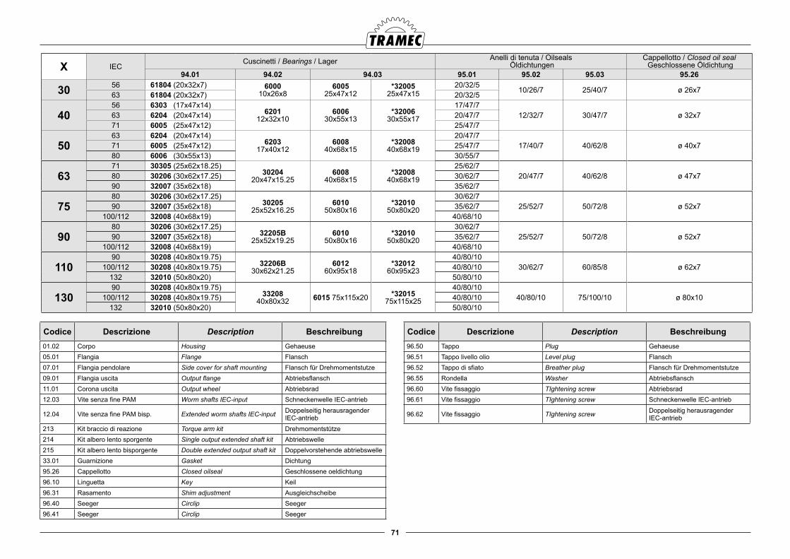
71
Codice Descrizione Description Beschreibung01.02 Corpo Housing Gehaeuse05.01 Flangia Flange Flansch07.01 Flangia pendolare Side cover for shaft mounting Flansch für Drehmomentstutze09.01 Flangia uscita Output flange Abtriebsflansch11.01 Corona uscita Output wheel Abtriebsrad12.03 Vite senza fine PAM Worm shafts IEC-input Schneckenwelle IEC-antrieb
12.04 Vite senza fine PAM bisp. Extended worm shafts IEC-input Doppelseitig herausragenderIEC-antrieb
213 Kit braccio di reazione Torque arm kit Drehmomentstütze214 Kit albero lento sporgente Single output extended shaft kit Abtriebswelle215 Kit albero lento bisporgente Double extended output shaft kit Doppelvorstehende abtriebswelle33.01 Guarnizione Gasket Dichtung95.26 Cappellotto Closed oilseal Geschlossene oeldichtung 96.10 Linguetta Key Keil96.31 Rasamento Shim adjustment Ausgleichscheibe96.40 Seeger Circlip Seeger96.41 Seeger Circlip Seeger
X IECCuscinetti / Bearings / Lager Anelli di tenuta / Oilseals
ÖldichtungenCappellotto / Closed oil seal Geschlossene Öldichtung
94.01 94.02 94.03 95.01 95.02 95.03 95.26
30 56 61804 (20x32x7) 600010x26x8
600525x47x12
*3200525x47x15
20/32/510/26/7 25/40/7 ø 26x7
63 61804 (20x32x7) 20/32/5
4056 6303 (17x47x14)
620112x32x10
600630x55x13
*3200630x55x17
17/47/712/32/7 30/47/7 ø 32x763 6204 (20x47x14) 20/47/7
71 6005 (25x47x12) 25/47/7
5063 6204 (20x47x14)
620317x40x12
600840x68x15
*3200840x68x19
20/47/717/40/7 40/62/8 ø 40x771 6005 (25x47x12) 25/47/7
80 6006 (30x55x13) 30/55/7
6371 30305 (25x62x18.25)
3020420x47x15.25
600840x68x15
*3200840x68x19
25/62/720/47/7 40/62/8 ø 47x780 30206 (30x62x17.25) 30/62/7
90 32007 (35x62x18) 35/62/7
7580 30206 (30x62x17.25)
3020525x52x16.25
601050x80x16
*3201050x80x20
30/62/725/52/7 50/72/8 ø 52x790 32007 (35x62x18) 35/62/7
100/112 32008 (40x68x19) 40/68/10
9080 30206 (30x62x17.25)
32205B25x52x19.25
601050x80x16
*3201050x80x20
30/62/725/52/7 50/72/8 ø 52x790 32007 (35x62x18) 35/62/7
100/112 32008 (40x68x19) 40/68/10
11090 30208 (40x80x19.75)
32206B30x62x21.25
601260x95x18
*3201260x95x23
40/80/1030/62/7 60/85/8 ø 62x7100/112 30208 (40x80x19.75) 40/80/10
132 32010 (50x80x20) 50/80/10
13090 30208 (40x80x19.75)
3320840x80x32 6015 75x115x20 *32015
75x115x25
40/80/1040/80/10 75/100/10 ø 80x10100/112 30208 (40x80x19.75) 40/80/10
132 32010 (50x80x20) 50/80/10
Codice Descrizione Description Beschreibung96.50 Tappo Plug Gehaeuse96.51 Tappo livello olio Level plug Flansch96.52 Tappo di sfiato Breather plug Flansch für Drehmomentstutze96.55 Rondella Washer Abtriebsflansch96.60 Vite fissaggio TIghtening screw Abtriebsrad96.61 Vite fissaggio TIghtening screw Schneckenwelle IEC-antrieb
96.62 Vite fissaggio TIghtening screw Doppelseitig herausragenderIEC-antrieb
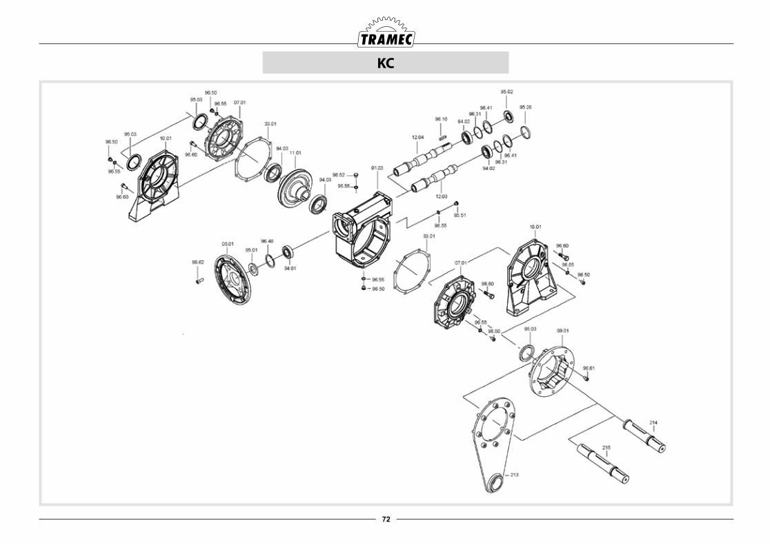
72
KC

73
KC IECCuscinetti / Bearings / Lager Anelli di tenuta / Oilseals
ÖldichtungenCappellotto / Closed oil seal Geschlossene Öldichtung
94.01 94.02 94.03 95.01 95.02 95.03 95.26
30 56 61804 (20x32x7) 600010x26x8
600525x47x12
*3200525x47x15
20/32/710/26/7 25/40/7 ø 26x763 61804 (20x32x7) 20/32/7
4056 6303 (17x47x14)
620112x32x10
600630x55x13
*3200630x55x17
17/47/712/32/7 30/47/7 ø 32x763 6204 (20x47x14) 30x55x17
71 6005 (25x47x12) 25/47/7
5063 6204 (20x47x14)
620317x40x12
600840x68x15
*3200840x68x19
20/47/717/40/7 40/62/8 ø 40x771 6005 (25x47x12) 25/47/7
80 6006 (30x55x13) 30/55/7
6371 30305 (25x62x18.25)
3020420x47x15.25
600840x68x15
*3200840x68x19
25/62/720/47/7 40/62/8 ø 47x780 30206 (30x62x17.25) 30/62/7
90 32007 (35x62x18) 35/62/7
7580 30206 (30x62x17.25)
3020525x52x16.25
601050x80x16
*3201050x80x20
30/62/725/52/7 50/72/8 ø 52x790 32007 (35x62x18) 35/62/7
100/112 32008 (40x68x19) 40/68/10
9080 30206 (30x62x17.25)
32205B25x52x19.25
601050x80x16
*3201050x80x20
30/62/725/52/7 50/72/8 ø 52x790 32007 (35x62x18) 35/62/7
100/112 32008 (40x68x19) 40/68/10
11090 30208 (40x80x19.75)
32206B30x62x21.25
601260x95x18
*3201260x95x23
40/80/1030/62/7 60/85/8 ø 62x7100/112 30208 (40x80x19.75) 40/80/10
132 32010 (50x80x20) 50/80/10
13090 30208 (40x80x19.75)
3320840x80x32 6015 75x115x20 *32015
75x115x25
40/80/1040/80/10 75/100/10 ø 80x10100/112 30208 (40x80x19.75) 40/80/10
132 32010 (50x80x20) 50/80/10* Cuscinetti a rulli conici a richiesta - Tapered roller bearings on request - Auf Wunsch Kegelrollenlager
Codice Descrizione Description Beschreibung01.03 Corpo Housing Gehaeuse05.01 Flangia Flange Flansch07.01 Flangia pendolare Side cover for shaft mounting Flansch für Drehmomentstutze09.01 Flangia uscita Output flange Abtriebsflansch10.01 Piede Foot Fußen11.01 Corona uscita Output wheel Abtriebsrad
12.03 Vite senza fine PAM Worm shafts IEC-input Schneckenwelle IEC-antrieb
12.04 Vite senza fine PAM bisp. Extended worm shafts IEC-input Doppelseitig herausragender IEC-antrieb
213 Kit braccio di reazione Torque arm kit Drehmomentstütze214 Kit albero lento sporgente Single output extended shaft kit Abtriebswelle215 Kit albero lento bisporgente Double extended output shaft kit Doppelvorstehende abtriebswelle33.01 Guarnizione Gasket Dichtung95.26 Cappellotto Closed oilseal Geschlossene oeldichtung 96.10 Linguetta Key Keil96.31 Rasamento Shim adjustment Ausgleichscheibe96.40 Seeger Circlip Seeger
Codice Descrizione Description Beschreibung96.41 Seeger Circlip Seeger96.50 Tappo Plug Schraube96.51 Tappo livello olio Level plug Oelstandschraube96.52 Tappo di sfiato Breather plug Entlueftungsschraube96.55 Rondella Washer Federring96.60 Vite fissaggio TIghtening screw Befestigungsschraube96.61 Vite fissaggio TIghtening screw Befestigungsschraube
96.62 Vite fissaggio TIghtening screw Befestigungsschraube
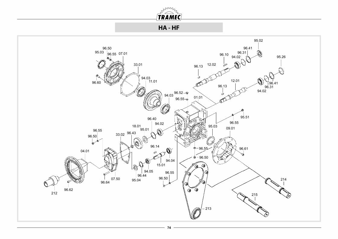
74
HA - HF
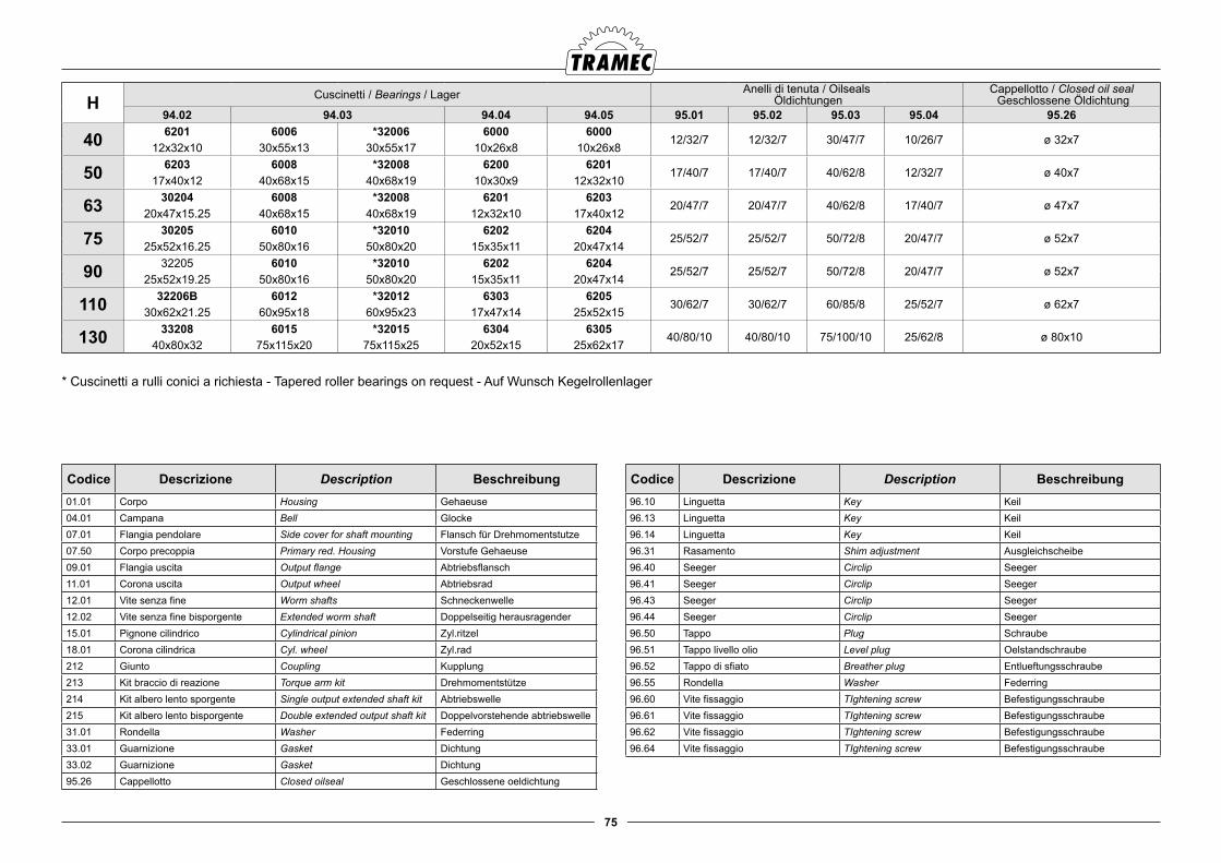
75
Codice Descrizione Description Beschreibung01.01 Corpo Housing Gehaeuse04.01 Campana Bell Glocke07.01 Flangia pendolare Side cover for shaft mounting Flansch für Drehmomentstutze07.50 Corpo precoppia Primary red. Housing Vorstufe Gehaeuse09.01 Flangia uscita Output flange Abtriebsflansch11.01 Corona uscita Output wheel Abtriebsrad12.01 Vite senza fine Worm shafts Schneckenwelle12.02 Vite senza fine bisporgente Extended worm shaft Doppelseitig herausragender15.01 Pignone cilindrico Cylindrical pinion Zyl.ritzel 18.01 Corona cilindrica Cyl. wheel Zyl.rad212 Giunto Coupling Kupplung213 Kit braccio di reazione Torque arm kit Drehmomentstütze214 Kit albero lento sporgente Single output extended shaft kit Abtriebswelle215 Kit albero lento bisporgente Double extended output shaft kit Doppelvorstehende abtriebswelle31.01 Rondella Washer Federring33.01 Guarnizione Gasket Dichtung33.02 Guarnizione Gasket Dichtung95.26 Cappellotto Closed oilseal Geschlossene oeldichtung
Codice Descrizione Description Beschreibung96.10 Linguetta Key Keil96.13 Linguetta Key Keil96.14 Linguetta Key Keil96.31 Rasamento Shim adjustment Ausgleichscheibe96.40 Seeger Circlip Seeger96.41 Seeger Circlip Seeger96.43 Seeger Circlip Seeger96.44 Seeger Circlip Seeger96.50 Tappo Plug Schraube96.51 Tappo livello olio Level plug Oelstandschraube96.52 Tappo di sfiato Breather plug Entlueftungsschraube96.55 Rondella Washer Federring96.60 Vite fissaggio TIghtening screw Befestigungsschraube96.61 Vite fissaggio TIghtening screw Befestigungsschraube96.62 Vite fissaggio TIghtening screw Befestigungsschraube96.64 Vite fissaggio TIghtening screw Befestigungsschraube
H Cuscinetti / Bearings / Lager Anelli di tenuta / Oilseals Öldichtungen
Cappellotto / Closed oil seal Geschlossene Öldichtung
94.02 94.03 94.04 94.05 95.01 95.02 95.03 95.04 95.26
40 6201 6006 *32006 6000 600012/32/7 12/32/7 30/47/7 10/26/7 ø 32x7
12x32x10 30x55x13 30x55x17 10x26x8 10x26x8
50 6203 6008 *32008 6200 620117/40/7 17/40/7 40/62/8 12/32/7 ø 40x7
17x40x12 40x68x15 40x68x19 10x30x9 12x32x10
63 30204 6008 *32008 6201 620320/47/7 20/47/7 40/62/8 17/40/7 ø 47x7
20x47x15.25 40x68x15 40x68x19 12x32x10 17x40x12
75 30205 6010 *32010 6202 620425/52/7 25/52/7 50/72/8 20/47/7 ø 52x7
25x52x16.25 50x80x16 50x80x20 15x35x11 20x47x14
90 32205 6010 *32010 6202 620425/52/7 25/52/7 50/72/8 20/47/7 ø 52x7
25x52x19.25 50x80x16 50x80x20 15x35x11 20x47x14
110 32206B 6012 *32012 6303 620530/62/7 30/62/7 60/85/8 25/52/7 ø 62x7
30x62x21.25 60x95x18 60x95x23 17x47x14 25x52x15
130 33208 6015 *32015 6304 630540/80/10 40/80/10 75/100/10 25/62/8 ø 80x10
40x80x32 75x115x20 75x115x25 20x52x15 25x62x17
* Cuscinetti a rulli conici a richiesta - Tapered roller bearings on request - Auf Wunsch Kegelrollenlager
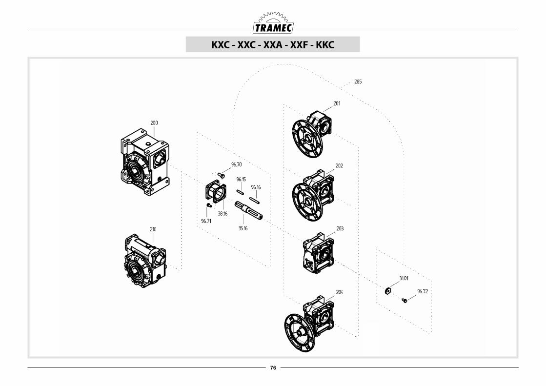
76
KXC - XXC - XXA - XXF - KKC
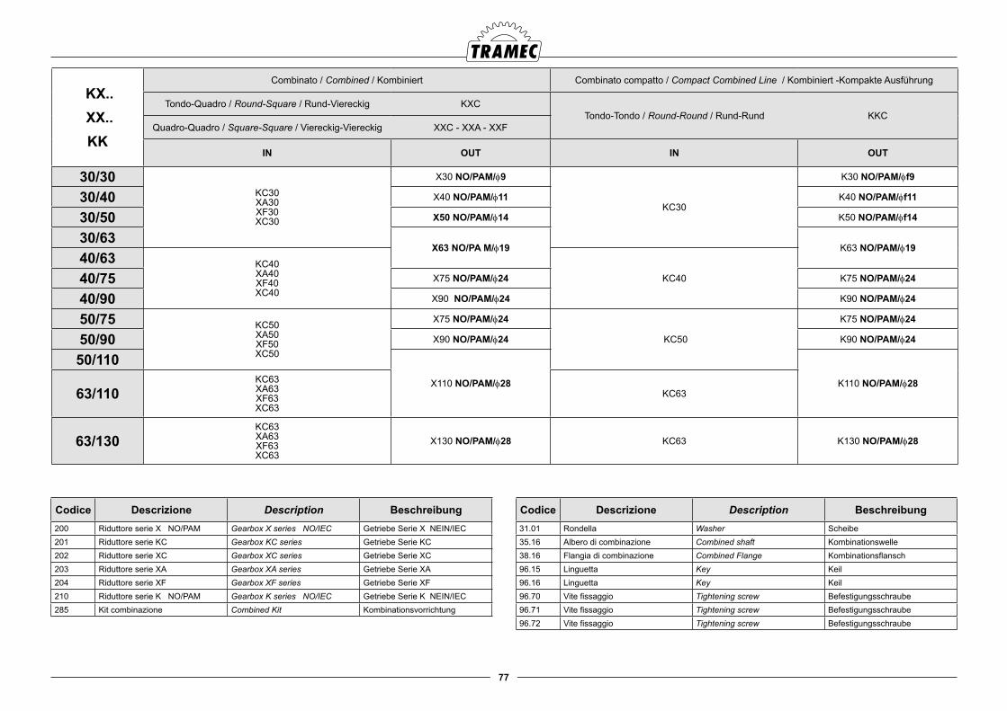
77
KX.. XX..KK
Combinato / Combined / Kombiniert Combinato compatto / Compact Combined Line / Kombiniert -Kompakte Ausführung
Tondo-Quadro / Round-Square / Rund-Viereckig KXCTondo-Tondo / Round-Round / Rund-Rund KKC
Quadro-Quadro / Square-Square / Viereckig-Viereckig XXC - XXA - XXF
IN OUT IN OUT
30/30KC30XA30XF30XC30
X30 NO/PAM/f9
KC30
K30 NO/PAM/ff9
30/40 X40 NO/PAM/f11 K40 NO/PAM/ff11
30/50 X50 NO/PAM/f14 K50 NO/PAM/ff14
30/63X63 NO/PA M/f19 K63 NO/PAM/f19
40/63 KC40XA40XF40XC40
KC4040/75 X75 NO/PAM/f24 K75 NO/PAM/f24
40/90 X90 NO/PAM/f24 K90 NO/PAM/f24
50/75 KC50XA50XF50XC50
X75 NO/PAM/f24
KC50
K75 NO/PAM/f24
50/90 X90 NO/PAM/f24 K90 NO/PAM/f24
50/110X110 NO/PAM/f28 K110 NO/PAM/f28
63/110KC63XA63XF63XC63
KC63
63/130KC63XA63XF63XC63
X130 NO/PAM/f28 KC63 K130 NO/PAM/f28
Codice Descrizione Description Beschreibung200 Riduttore serie X NO/PAM Gearbox X series NO/IEC Getriebe Serie X NEIN/IEC201 Riduttore serie KC Gearbox KC series Getriebe Serie KC202 Riduttore serie XC Gearbox XC series Getriebe Serie XC203 Riduttore serie XA Gearbox XA series Getriebe Serie XA204 Riduttore serie XF Gearbox XF series Getriebe Serie XF210 Riduttore serie K NO/PAM Gearbox K series NO/IEC Getriebe Serie K NEIN/IEC285 Kit combinazione Combined Kit Kombinationsvorrichtung
Codice Descrizione Description Beschreibung31.01 Rondella Washer Scheibe35.16 Albero di combinazione Combined shaft Kombinationswelle38.16 Flangia di combinazione Combined Flange Kombinationsflansch96.15 Linguetta Key Keil96.16 Linguetta Key Keil96.70 Vite fissaggio Tightening screw Befestigungsschraube96.71 Vite fissaggio Tightening screw Befestigungsschraube96.72 Vite fissaggio Tightening screw Befestigungsschraube
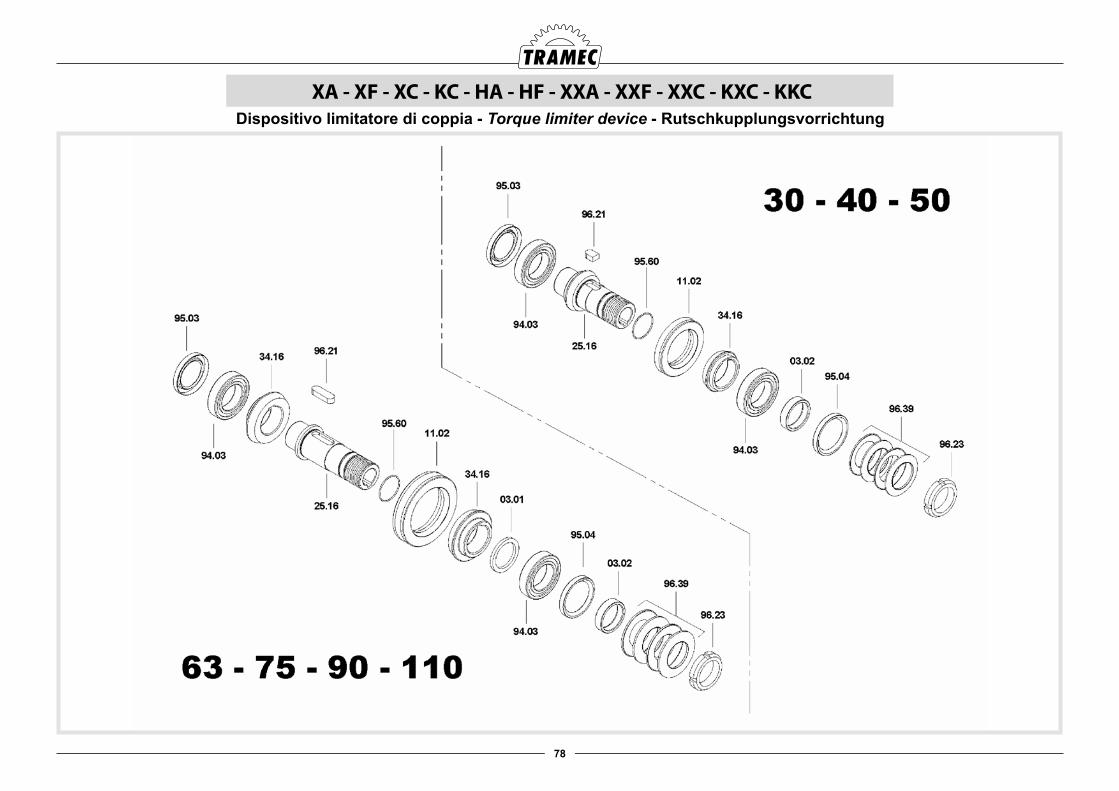
78
XA - XF - XC - KC - HA - HF - XXA - XXF - XXC - KXC - KKCDispositivo limitatore di coppia - Torque limiter device - Rutschkupplungsvorrichtung
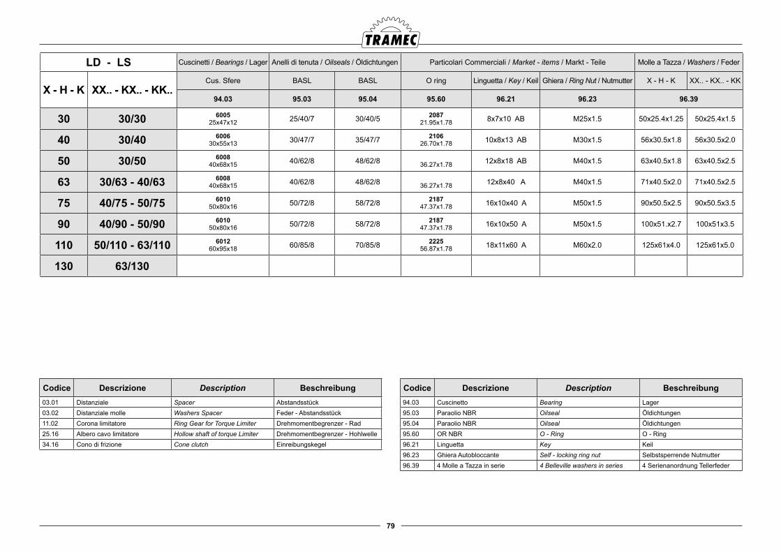
79
Codice Descrizione Description Beschreibung03.01 Distanziale Spacer Abstandsstück03.02 Distanziale molle Washers Spacer Feder - Abstandsstück11.02 Corona limitatore Ring Gear for Torque Limiter Drehmomentbegrenzer - Rad25.16 Albero cavo limitatore Hollow shaft of torque Limiter Drehmomentbegrenzer - Hohlwelle34.16 Cono di frizione Cone clutch Einreibungskegel
Codice Descrizione Description Beschreibung94.03 Cuscinetto Bearing Lager95.03 Paraolio NBR Oilseal Öldichtungen95.04 Paraolio NBR Oilseal Öldichtungen95.60 OR NBR O - Ring O - Ring96.21 Linguetta Key Keil96.23 Ghiera Autobloccante Self - locking ring nut Selbstsperrende Nutmutter96.39 4 Molle a Tazza in serie 4 Belleville washers in series 4 Serienanordnung Tellerfeder
LD - LS Cuscinetti / Bearings / Lager Anelli di tenuta / Oilseals / Öldichtungen Particolari Commerciali / Market - items / Markt - Teile Molle a Tazza / Washers / Feder
X - H - K XX.. - KX.. - KK..Cus. Sfere BASL BASL O ring Linguetta / Key / Keil Ghiera / Ring Nut / Nutmutter X - H - K XX.. - KX.. - KK
94.03 95.03 95.04 95.60 96.21 96.23 96.39
30 30/30 600525x47x12 25/40/7 30/40/5 2087
21.95x1.78 8x7x10 AB M25x1.5 50x25.4x1.25 50x25.4x1.5
40 30/40 600630x55x13 30/47/7 35/47/7 2106
26.70x1.78 10x8x13 AB M30x1.5 56x30.5x1.8 56x30.5x2.0
50 30/50 600840x68x15 40/62/8 48/62/8 36.27x1.78 12x8x18 AB M40x1.5 63x40.5x1.8 63x40.5x2.5
63 30/63 - 40/63 600840x68x15 40/62/8 48/62/8 36.27x1.78 12x8x40 A M40x1.5 71x40.5x2.0 71x40.5x2.5
75 40/75 - 50/75 601050x80x16 50/72/8 58/72/8 2187
47.37x1.78 16x10x40 A M50x1.5 90x50.5x2.5 90x50.5x3.5
90 40/90 - 50/90 601050x80x16 50/72/8 58/72/8 2187
47.37x1.78 16x10x50 A M50x1.5 100x51.x2.7 100x51x3.5
110 50/110 - 63/110 601260x95x18 60/85/8 70/85/8 2225
56.87x1.78 18x11x60 A M60x2.0 125x61x4.0 125x61x5.0
130 63/130
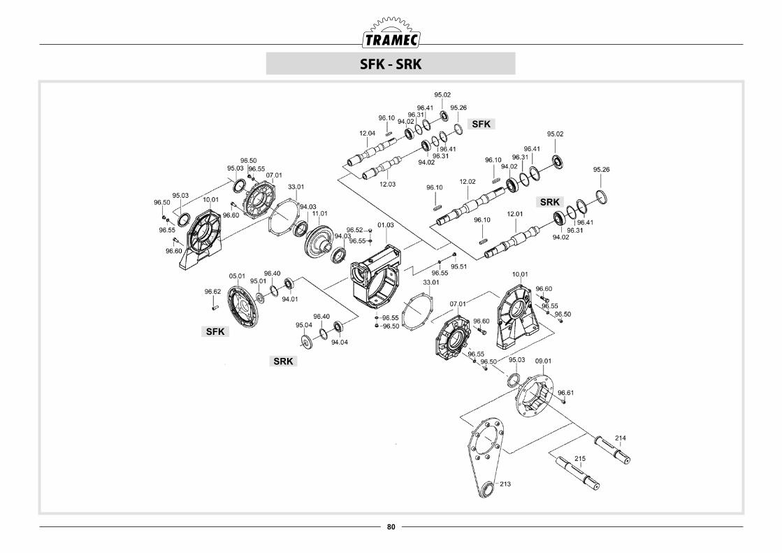
80
SFK
SRK
SFK
SRK
SFK - SRK

81
SFKSRK IEC
Cuscinetti / Bearings / Lager Anelli di tenuta / Oilseals Öldichtungen
Cappellotto Closed oil seal
Geschlossene Öldichtung
94.01 94.02 94.03 94.04 95.01 95.02 95.03 95.04 95.26
30 56 61804 (20x32x7) 600010x26x8
600525x47x12
*3200525x47x15
620112x32x10
20/32/710/26/7 25/40/7 12/32/7 ø 26x7
63 61804 (20x32x7) 20/32/7
4056 6303 (17x47x14)
620112x32x10
600630x55x13
*3200630x55x17
630317x47x14
17/47/712/32/7 30/47/7
(30/45/8)1 17/47/7 ø 32x763 6204 (20x47x14) 20/47/771 6005 (25x47x12) 25/47/7
5063 6204 (20x47x14)
620317x40x12
600840x68x15
*3200840x68x19
620420x47x14
20/47/717/40/7 40/62/8
(40/56/8)1 20/47/7 ø 40x771 6005 (25x47x12) 25/47/780 6006 (30x55x13) 30/55/7
6371 30305 (25x62x18.25)
3020420x47x15.25
600840x68x15
*3200840x68x19
3030525x62x18.25
25/62/720/47/7 40/62/8 25/62/7 ø 47x780 30206 (30x62x17.25) 30/62/7
90 32007 (35x62x18) 35/62/7
7571 30206 (30x62x17.25)
3020525x52x16.25
601050x80x16
*3201050x80x20
3030525x62x18.25
30/62/7
25/52/7 50/72/8 25/62/7 ø 52x780 30206 (30x62x17.25) 30/62/790 32007 (35x62x18) 35/62/7
100/112 32008 (40x68x19) 40/68/10
Codice Descrizione Description Beschreibung01.03 Corpo Housing Gehaeuse05.01 Flangia Flange Flansch07.01 Flangia pendolare Side cover for shaft mounting Flansch für Drehmomentstutze09.01 Flangia uscita Output flange Abtriebsflansch10.01 Piede Foot Fußen11.01 Corona uscita Output wheel Abtriebsrad12.01 Vite senza fine Worm shafts Schneckenwelle12.02 Vite senza fine bisporgente Extended worm shaft Doppelseitig herausragender
12.03 Vite senza fine PAM Worm shafts IEC-input Schneckenwelle IEC-antrieb
12.04 Vite senza fine PAM bisp. Extended worm shafts IEC-input Doppelseitig herausragender IEC-antrieb
213 Kit braccio di reazione Torque arm kit Drehmomentstütze214 Kit albero lento sporgente Single output extended shaft kit Abtriebswelle215 Kit albero lento bisporgente Double extended output shaft kit Doppelvorstehende abtriebswelle33.01 Guarnizione Gasket Dichtung95.26 Cappellotto Closed oilseal Geschlossene oeldichtung 96.10 Linguetta Key Keil96.31 Rasamento Shim adjustment Ausgleichscheibe96.40 Seeger Circlip Seeger
Codice Descrizione Description Beschreibung96.41 Seeger Circlip Seeger96.50 Tappo Plug Schraube96.51 Tappo livello olio Level plug Oelstandschraube96.52 Tappo di sfiato Breather plug Entlueftungsschraube96.55 Rondella Washer Federring96.60 Vite fissaggio TIghtening screw Befestigungsschraube96.61 Vite fissaggio TIghtening screw Befestigungsschraube
96.62 Vite fissaggio TIghtening screw Befestigungsschraube
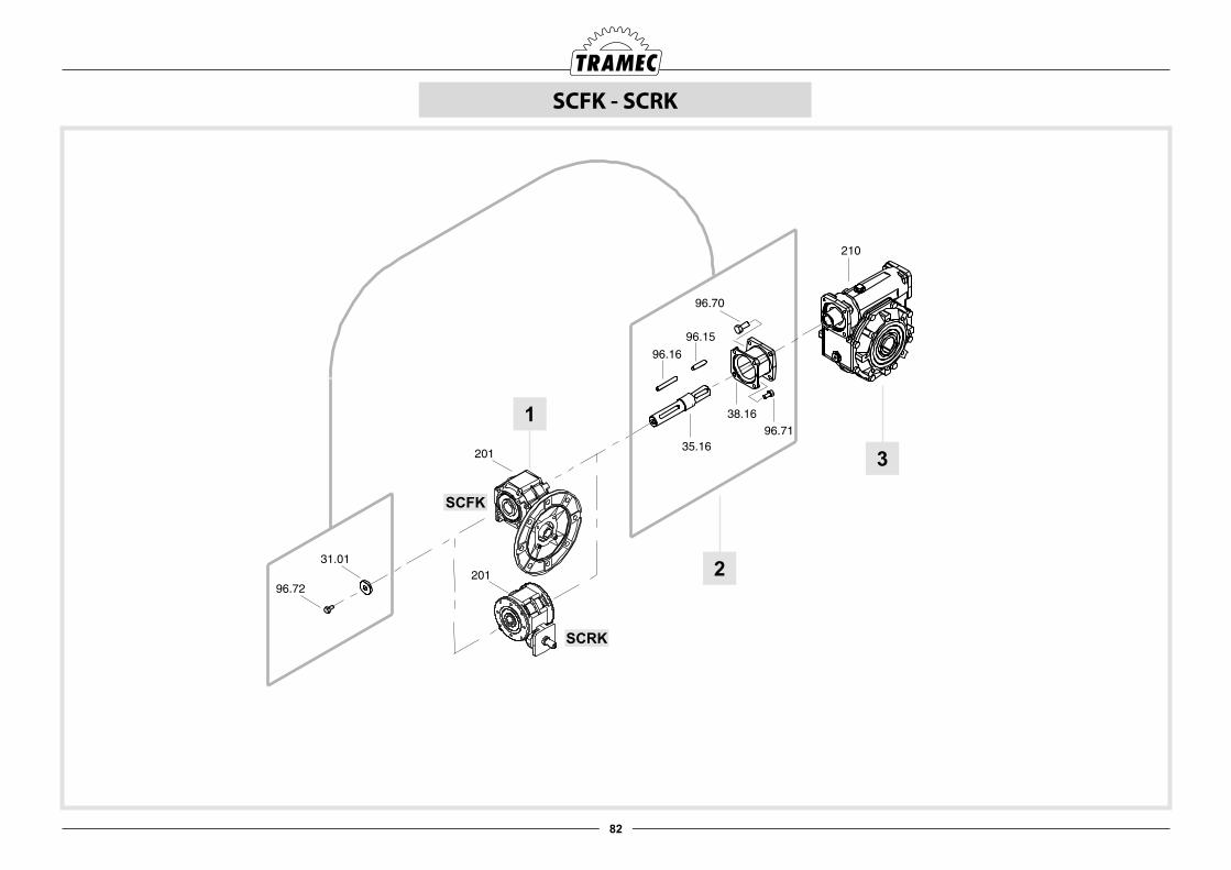
82
SCFK - SCRK
2
3
1
SCFK
SCRK
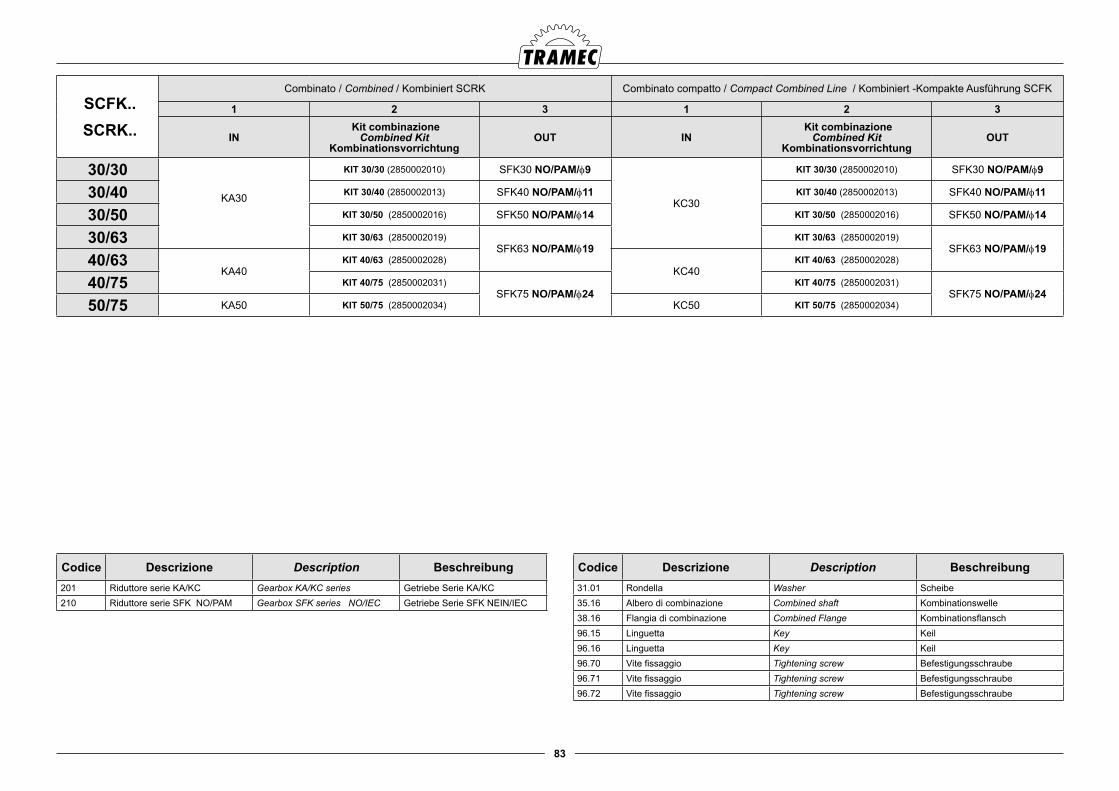
83
Codice Descrizione Description Beschreibung201 Riduttore serie KA/KC Gearbox KA/KC series Getriebe Serie KA/KC210 Riduttore serie SFK NO/PAM Gearbox SFK series NO/IEC Getriebe Serie SFK NEIN/IEC
Codice Descrizione Description Beschreibung31.01 Rondella Washer Scheibe35.16 Albero di combinazione Combined shaft Kombinationswelle38.16 Flangia di combinazione Combined Flange Kombinationsflansch96.15 Linguetta Key Keil96.16 Linguetta Key Keil96.70 Vite fissaggio Tightening screw Befestigungsschraube96.71 Vite fissaggio Tightening screw Befestigungsschraube96.72 Vite fissaggio Tightening screw Befestigungsschraube
SCFK.. SCRK..
Combinato / Combined / Kombiniert SCRK Combinato compatto / Compact Combined Line / Kombiniert -Kompakte Ausführung SCFK
1 2 3 1 2 3
IN Kit combinazione
Combined KitKombinationsvorrichtung
OUT IN Kit combinazione
Combined KitKombinationsvorrichtung
OUT
30/30KA30
KIT 30/30 (2850002010) SFK30 NO/PAM/f9
KC30
KIT 30/30 (2850002010) SFK30 NO/PAM/f9
30/40 KIT 30/40 (2850002013) SFK40 NO/PAM/f11 KIT 30/40 (2850002013) SFK40 NO/PAM/f11
30/50 KIT 30/50 (2850002016) SFK50 NO/PAM/f14 KIT 30/50 (2850002016) SFK50 NO/PAM/f14
30/63 KIT 30/63 (2850002019)SFK63 NO/PAM/f19
KIT 30/63 (2850002019)SFK63 NO/PAM/f19
40/63KA40
KIT 40/63 (2850002028)KC40
KIT 40/63 (2850002028)
40/75 KIT 40/75 (2850002031)SFK75 NO/PAM/f24
KIT 40/75 (2850002031)SFK75 NO/PAM/f24
50/75 KA50 KIT 50/75 (2850002034) KC50 KIT 50/75 (2850002034)
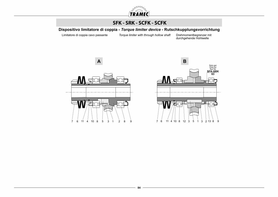
84
Drehmomentbegrenzer mit durchgehende Hohlwelle
Torque limiter with through hollow shaftLimitatore di coppia cavo passante
SFK - SRK - SCFK - SCFKDispositivo limitatore di coppia - Torque limiter device - Rutschkupplungsvorrichtung
982315312 1381067
Solo per
Nur fürOnly for
SFK-SRK
63
98213581011 114 467
A B
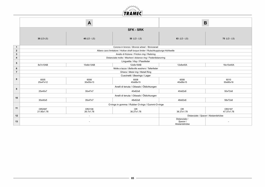
85
A BSFK - SRK
30 (LD-LS) 40 (LD - LS) 50 (LD - LS) 63 (LD - LS) 75 (LD - LS)
1 Corona in bronzo / Bronze wheel / Bronzerad2 Albero cavo limitatore / Hollow shaft torque limiter / Rutschkupplungs-Hohlwelle3 Anello di frizione / Friction ring / Reibring4 Distanziale molle / Washers’ distance ring / Federdistanzring
5Linguetta / Key / Passfeder
8x7x10AB 10x8x13AB 12x8x18AB 12x8x40A 16x10x40A6 Molle a tazza / Belleville washers / Tellerfeder7 Ghiera / Metal ring / Metall Ring
8Cuscinetti / Bearings / Lager
6005 25x47x12
600630x55x13
600840x68x15
600840x68x15
601050x80x16
9Anelli di tenuta / Oilseals / Öldichtungen
25x40x7 30x47x7 40x62x8 40x62x8 50x72x8
10Anelli di tenuta / Oilseals / Öldichtungen
30x40x5 35x47x7 48x62x8 48x62x8 58x72x8
11 O-rings in gomma / Rubber O-rings / Gummi-O-ringe
OR2087 21.95x1.78
OR210626.7x1.78
OR36.27x1.78
OR36.27x1.78
OR218747.37x1.78
12 - Distanziale / Spacer / Abstandshülse
13 -Distanziale /
Spacer / Abstandshülse
-

86
BFK -BRK
BFK
BRK
BFK
BRK
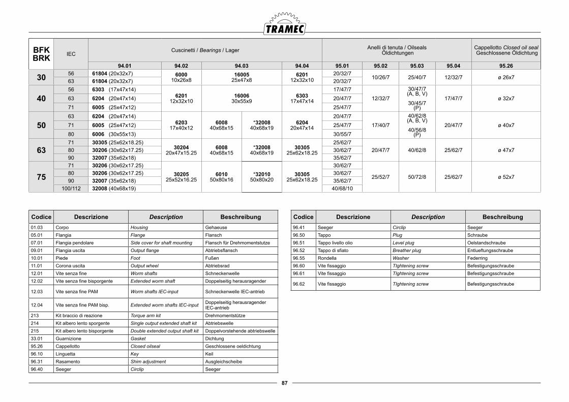
87
BFKBRK IEC
Cuscinetti / Bearings / Lager Anelli di tenuta / Oilseals Öldichtungen
Cappellotto Closed oil seal Geschlossene Öldichtung
94.01 94.02 94.03 94.04 95.01 95.02 95.03 95.04 95.26
30 56 61804 (20x32x7) 600010x26x8
1600525x47x8
620112x32x10
20/32/710/26/7 25/40/7 12/32/7 ø 26x7
63 61804 (20x32x7) 20/32/7
4056 6303 (17x47x14)
620112x32x10
1600630x55x9
630317x47x14
17/47/712/32/7
30/47/7 (A, B, V)
30/45/7
(P)
17/47/7 ø 32x763 6204 (20x47x14) 20/47/771 6005 (25x47x12) 25/47/7
5063 6204 (20x47x14)
620317x40x12
600840x68x15
*3200840x68x19
620420x47x14
20/47/717/40/7
40/62/8(A, B, V)
40/56/8(P)
20/47/7 ø 40x771 6005 (25x47x12) 25/47/780 6006 (30x55x13) 30/55/7
6371 30305 (25x62x18.25)
3020420x47x15.25
600840x68x15
*3200840x68x19
3030525x62x18.25
25/62/720/47/7 40/62/8 25/62/7 ø 47x780 30206 (30x62x17.25) 30/62/7
90 32007 (35x62x18) 35/62/7
7571 30206 (30x62x17.25)
3020525x52x16.25
601050x80x16
*3201050x80x20
3030525x62x18.25
30/62/7
25/52/7 50/72/8 25/62/7 ø 52x780 30206 (30x62x17.25) 30/62/790 32007 (35x62x18) 35/62/7
100/112 32008 (40x68x19) 40/68/10
Codice Descrizione Description Beschreibung01.03 Corpo Housing Gehaeuse05.01 Flangia Flange Flansch07.01 Flangia pendolare Side cover for shaft mounting Flansch für Drehmomentstutze09.01 Flangia uscita Output flange Abtriebsflansch10.01 Piede Foot Fußen11.01 Corona uscita Output wheel Abtriebsrad12.01 Vite senza fine Worm shafts Schneckenwelle12.02 Vite senza fine bisporgente Extended worm shaft Doppelseitig herausragender
12.03 Vite senza fine PAM Worm shafts IEC-input Schneckenwelle IEC-antrieb
12.04 Vite senza fine PAM bisp. Extended worm shafts IEC-input Doppelseitig herausragender IEC-antrieb
213 Kit braccio di reazione Torque arm kit Drehmomentstütze214 Kit albero lento sporgente Single output extended shaft kit Abtriebswelle215 Kit albero lento bisporgente Double extended output shaft kit Doppelvorstehende abtriebswelle33.01 Guarnizione Gasket Dichtung95.26 Cappellotto Closed oilseal Geschlossene oeldichtung 96.10 Linguetta Key Keil96.31 Rasamento Shim adjustment Ausgleichscheibe96.40 Seeger Circlip Seeger
Codice Descrizione Description Beschreibung96.41 Seeger Circlip Seeger96.50 Tappo Plug Schraube96.51 Tappo livello olio Level plug Oelstandschraube96.52 Tappo di sfiato Breather plug Entlueftungsschraube96.55 Rondella Washer Federring96.60 Vite fissaggio TIghtening screw Befestigungsschraube96.61 Vite fissaggio TIghtening screw Befestigungsschraube
96.62 Vite fissaggio TIghtening screw Befestigungsschraube
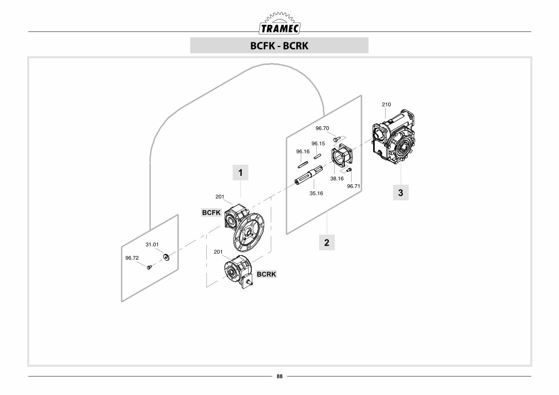
88
2
3
1
BCFK
BCRK
BCFK - BCRK
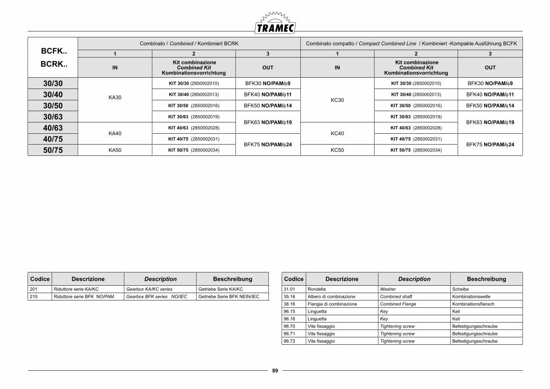
89
Codice Descrizione Description Beschreibung201 Riduttore serie KA/KC Gearbox KA/KC series Getriebe Serie KA/KC210 Riduttore serie BFK NO/PAM Gearbox BFK series NO/IEC Getriebe Serie BFK NEIN/IEC
Codice Descrizione Description Beschreibung31.01 Rondella Washer Scheibe35.16 Albero di combinazione Combined shaft Kombinationswelle38.16 Flangia di combinazione Combined Flange Kombinationsflansch96.15 Linguetta Key Keil96.16 Linguetta Key Keil96.70 Vite fissaggio Tightening screw Befestigungsschraube96.71 Vite fissaggio Tightening screw Befestigungsschraube96.72 Vite fissaggio Tightening screw Befestigungsschraube
BCFK.. BCRK..
Combinato / Combined / Kombiniert BCRK Combinato compatto / Compact Combined Line / Kombiniert -Kompakte Ausführung BCFK
1 2 3 1 2 3
IN Kit combinazione
Combined KitKombinationsvorrichtung
OUT IN Kit combinazione
Combined KitKombinationsvorrichtung
OUT
30/30KA30
KIT 30/30 (2850002010) BFK30 NO/PAM/f9
KC30
KIT 30/30 (2850002010) BFK30 NO/PAM/f9
30/40 KIT 30/40 (2850002013) BFK40 NO/PAM/f11 KIT 30/40 (2850002013) BFK40 NO/PAM/f11
30/50 KIT 30/50 (2850002016) BFK50 NO/PAM/f14 KIT 30/50 (2850002016) BFK50 NO/PAM/f14
30/63 KIT 30/63 (2850002019)BFK63 NO/PAM/f19
KIT 30/63 (2850002019)BFK63 NO/PAM/f19
40/63KA40
KIT 40/63 (2850002028)KC40
KIT 40/63 (2850002028)
40/75 KIT 40/75 (2850002031)BFK75 NO/PAM/f24
KIT 40/75 (2850002031)BFK75 NO/PAM/f24
50/75 KA50 KIT 50/75 (2850002034) KC50 KIT 50/75 (2850002034)
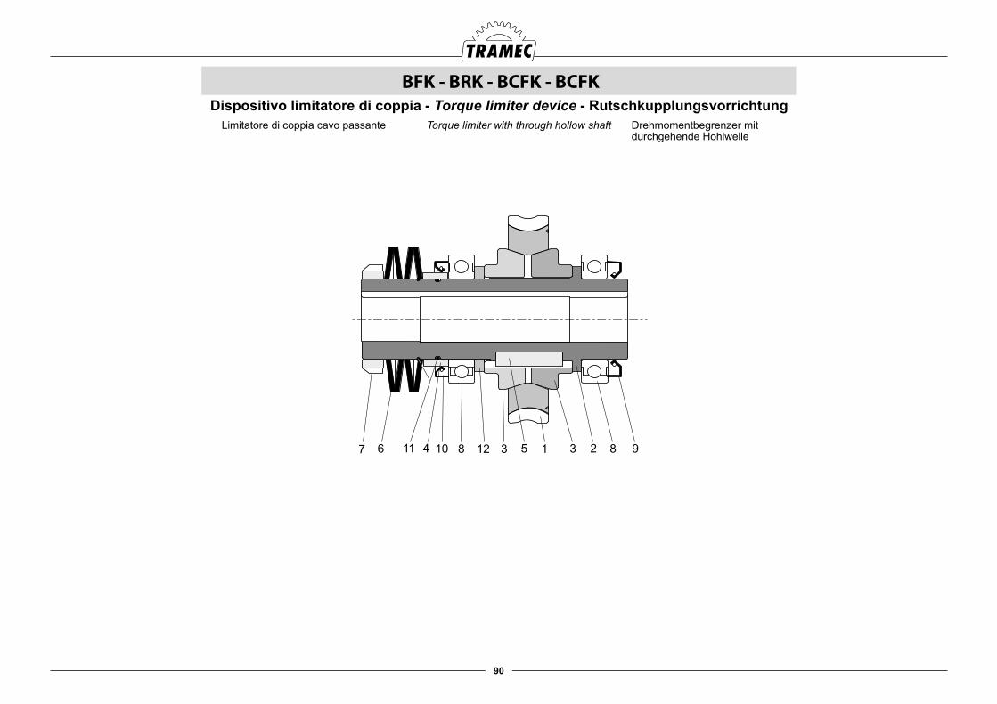
90
BFK - BRK - BCFK - BCFK
9823153128106798213581011 114 467
Drehmomentbegrenzer mit durchgehende Hohlwelle
Torque limiter with through hollow shaftLimitatore di coppia cavo passante
Dispositivo limitatore di coppia - Torque limiter device - Rutschkupplungsvorrichtung

91
BFK - BRK
63 (LD - LS) 75 (LD - LS)
1 Corona in bronzo / Bronze wheel / Bronzerad
2 Albero cavo limitatore / Hollow shaft torque limiter / Rutschkupplungs-Hohlwelle
3 Anello di frizione / Friction ring / Reibring
4 Distanziale molle / Washers’ distance ring / Federdistanzring
5Linguetta / Key / Passfeder
12x8x40A 16x10x40A
6 Molle a tazza / Belleville washers / Tellerfeder
7 Ghiera / Metal ring / Metall Ring
8Cuscinetti / Bearings / Lager
600840x68x15
601050x80x16
9Anelli di tenuta / Oilseals / Öldichtungen
40x62x8 50x72x8
10Anelli di tenuta / Oilseals / Öldichtungen
48x62x8 58x72x8
11O-rings in gomma / Rubber O-rings / Gummi-O-ringe
OR36.27x1.78
OR218747.37x1.78
12 Distanziale / Spacer / Abstandshülse
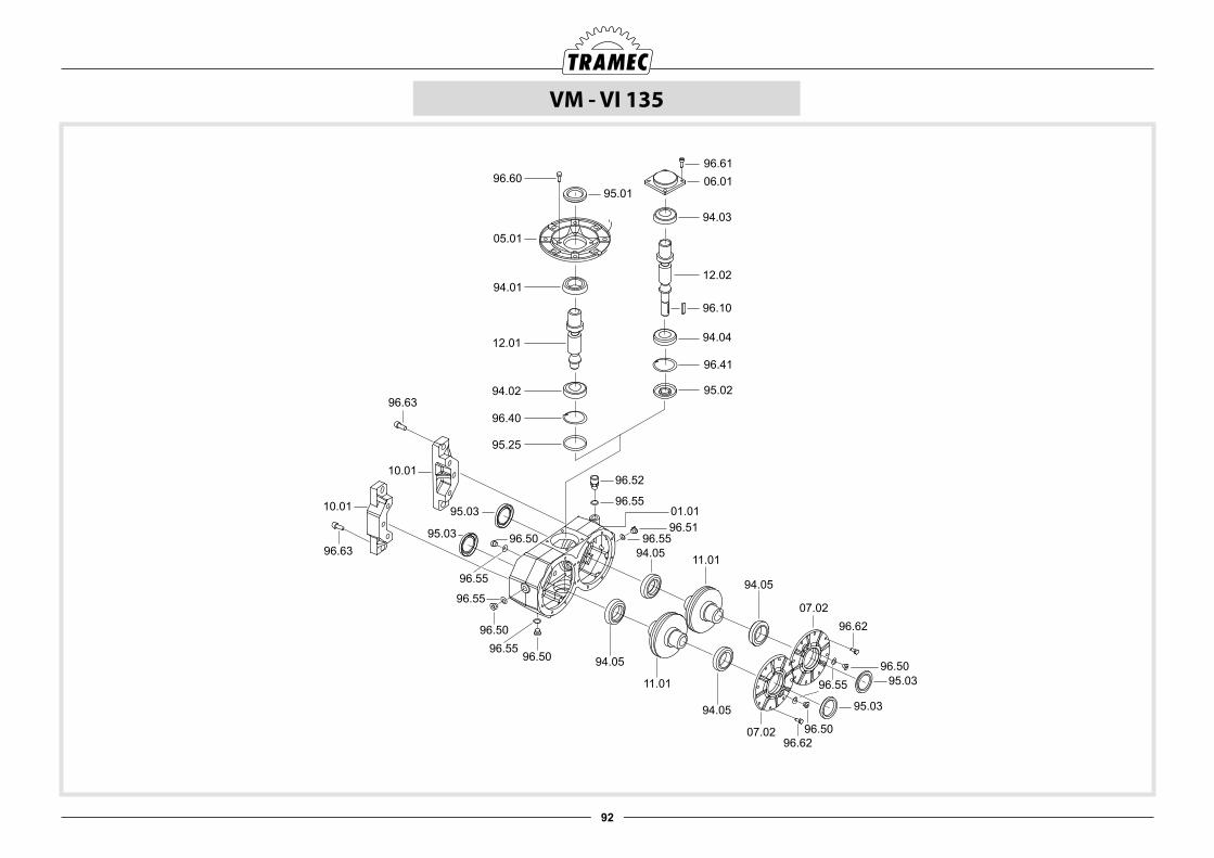
92
VM - VI 135
96.6106.01
94.03
96.10
12.02
94.04
96.41
95.02
95.0196.60
05.01
94.01
12.01
94.02
96.40
95.25
96.52
96.5501.0196.51
96.5594.05 11.01
94.05
07.0296.62
96.5095.03
95.03
96.6207.02
96.55
94.05
11.01
94.05
96.55
96.50
96.5096.55
96.63
96.63
10.01
10.01
95.03
95.03 96.50
96.55
96.50
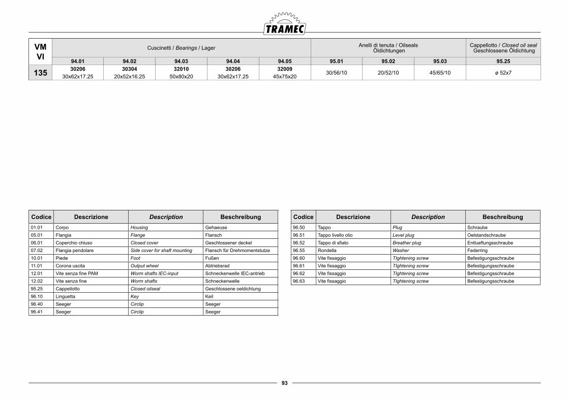
93
Codice Descrizione Description Beschreibung01.01 Corpo Housing Gehaeuse05.01 Flangia Flange Flansch06.01 Coperchio chiuso Closed cover Geschlossener deckel07.02 Flangia pendolare Side cover for shaft mounting Flansch für Drehmomentstutze10.01 Piede Foot Fußen11.01 Corona uscita Output wheel Abtriebsrad12.01 Vite senza fine PAM Worm shafts IEC-input Schneckenwelle IEC-antrieb12.02 Vite senza fine Worm shafts Schneckenwelle95.25 Cappellotto Closed oilseal Geschlossene oeldichtung 96.10 Linguetta Key Keil96.40 Seeger Circlip Seeger96.41 Seeger Circlip Seeger
Codice Descrizione Description Beschreibung96.50 Tappo Plug Schraube96.51 Tappo livello olio Level plug Oelstandschraube96.52 Tappo di sfiato Breather plug Entlueftungsschraube96.55 Rondella Washer Federring96.60 Vite fissaggio TIghtening screw Befestigungsschraube96.61 Vite fissaggio TIghtening screw Befestigungsschraube96.62 Vite fissaggio TIghtening screw Befestigungsschraube96.63 Vite fissaggio TIghtening screw Befestigungsschraube
VMVI
Cuscinetti / Bearings / Lager Anelli di tenuta / Oilseals Öldichtungen
Cappellotto / Closed oil seal Geschlossene Öldichtung
94.01 94.02 94.03 94.04 94.05 95.01 95.02 95.03 95.25
135 30206 30304 32010 30206 3200930/56/10 20/52/10 45/65/10 ø 52x7
30x62x17.25 20x52x16.25 50x80x20 30x62x17.25 45x75x20
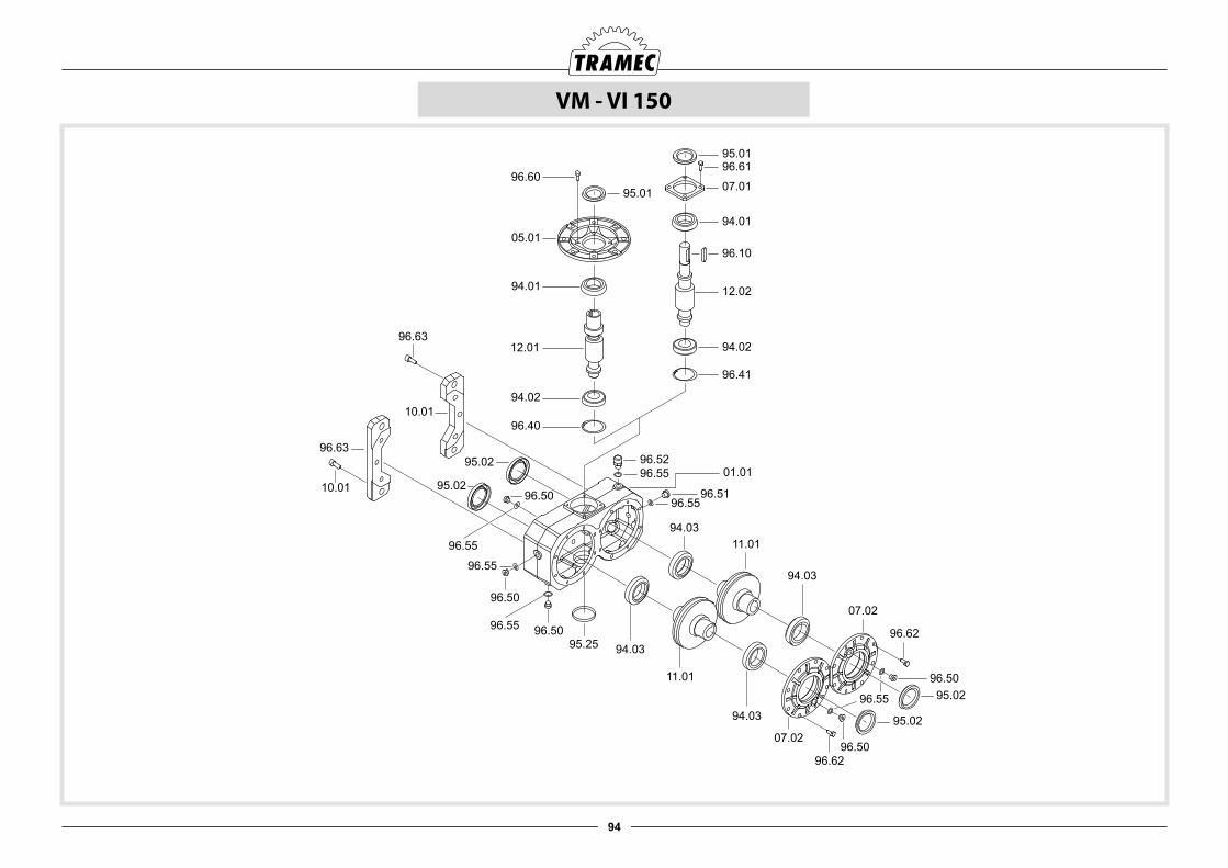
94
VM - VI 150
95.0196.61
07.01
94.01
96.10
12.02
94.02
96.41
95.0196.60
05.01
94.01
12.01
94.02
96.40
96.5296.55 01.01
96.5196.55
94.0311.01
94.03
07.02
96.62
96.5095.02
95.02
96.62
07.02
96.5594.03
11.01
94.0395.25
96.55
96.50
96.50
96.55
96.63
96.63
10.01
10.01
95.02
95.0296.50
96.55
96.50
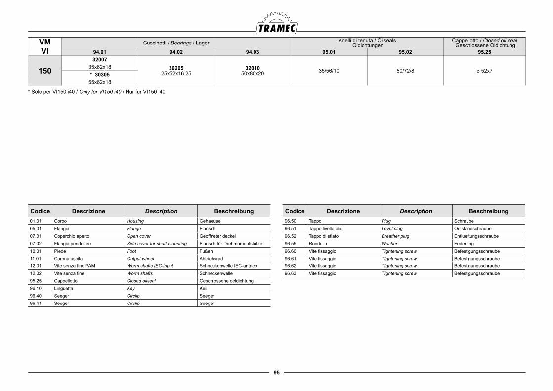
95
VMVI
Cuscinetti / Bearings / Lager Anelli di tenuta / Oilseals Öldichtungen
Cappellotto / Closed oil seal Geschlossene Öldichtung
94.01 94.02 94.03 95.01 95.02 95.25
15032007
3020525x52x16.25
3201050x80x20 35/56/10 50/72/8 ø 52x7
35x62x18* 30305
55x62x18
* Solo per VI150 i40 / Only for VI150 i40 / Nur fur VI150 i40
Codice Descrizione Description Beschreibung01.01 Corpo Housing Gehaeuse05.01 Flangia Flange Flansch07.01 Coperchio aperto Open cover Geoffneter deckel07.02 Flangia pendolare Side cover for shaft mounting Flansch für Drehmomentstutze10.01 Piede Foot Fußen11.01 Corona uscita Output wheel Abtriebsrad12.01 Vite senza fine PAM Worm shafts IEC-input Schneckenwelle IEC-antrieb12.02 Vite senza fine Worm shafts Schneckenwelle95.25 Cappellotto Closed oilseal Geschlossene oeldichtung 96.10 Linguetta Key Keil96.40 Seeger Circlip Seeger96.41 Seeger Circlip Seeger
Codice Descrizione Description Beschreibung96.50 Tappo Plug Schraube96.51 Tappo livello olio Level plug Oelstandschraube96.52 Tappo di sfiato Breather plug Entlueftungsschraube96.55 Rondella Washer Federring96.60 Vite fissaggio TIghtening screw Befestigungsschraube96.61 Vite fissaggio TIghtening screw Befestigungsschraube96.62 Vite fissaggio TIghtening screw Befestigungsschraube96.63 Vite fissaggio TIghtening screw Befestigungsschraube
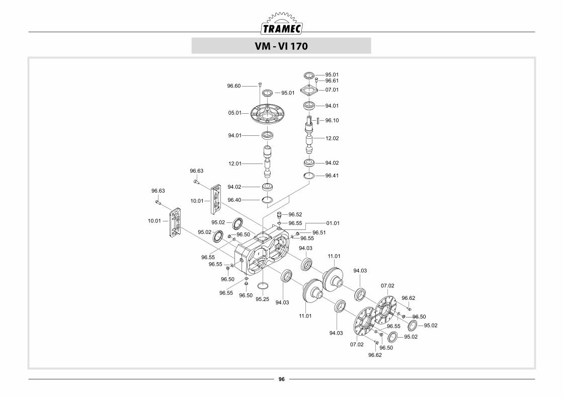
96
VM - VI 170
95.0196.61
07.01
94.01
96.10
12.02
94.02
96.41
95.0196.60
05.01
94.01
12.01
94.02
96.40
96.5296.55 01.01
96.5196.55
94.0311.01
94.03
07.02
96.62
96.5095.02
95.02
96.62
07.02
96.5594.03
11.01
94.0395.25
96.55
96.50
96.50
96.55
96.63
96.63
10.01
10.01
95.02
95.02 96.50
96.55
96.50
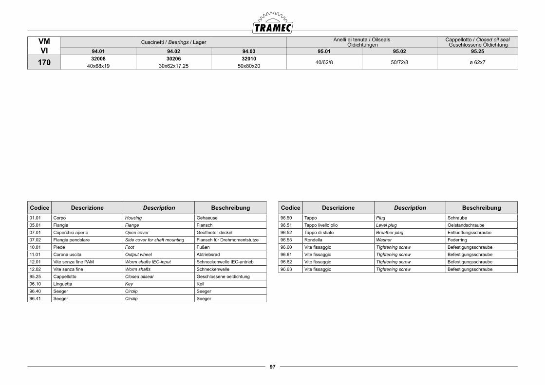
97
VMVI
Cuscinetti / Bearings / Lager Anelli di tenuta / Oilseals Öldichtungen
Cappellotto / Closed oil seal Geschlossene Öldichtung
94.01 94.02 94.03 95.01 95.02 95.25
170 32008 30206 3201040/62/8 50/72/8 ø 62x7
40x68x19 30x62x17.25 50x80x20
Codice Descrizione Description Beschreibung01.01 Corpo Housing Gehaeuse05.01 Flangia Flange Flansch07.01 Coperchio aperto Open cover Geoffneter deckel07.02 Flangia pendolare Side cover for shaft mounting Flansch für Drehmomentstutze10.01 Piede Foot Fußen11.01 Corona uscita Output wheel Abtriebsrad12.01 Vite senza fine PAM Worm shafts IEC-input Schneckenwelle IEC-antrieb12.02 Vite senza fine Worm shafts Schneckenwelle95.25 Cappellotto Closed oilseal Geschlossene oeldichtung 96.10 Linguetta Key Keil96.40 Seeger Circlip Seeger96.41 Seeger Circlip Seeger
Codice Descrizione Description Beschreibung96.50 Tappo Plug Schraube96.51 Tappo livello olio Level plug Oelstandschraube96.52 Tappo di sfiato Breather plug Entlueftungsschraube96.55 Rondella Washer Federring96.60 Vite fissaggio TIghtening screw Befestigungsschraube96.61 Vite fissaggio TIghtening screw Befestigungsschraube96.62 Vite fissaggio TIghtening screw Befestigungsschraube96.63 Vite fissaggio TIghtening screw Befestigungsschraube
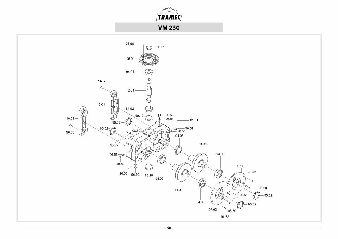
98
VM 230
95.0196.60
05.01
94.01
12.01
94.02
96.40 96.5296.55 01.01
96.5196.55
94.03
11.01
94.03
07.02
96.62
96.50
95.02
95.02
96.62
07.02
96.55
94.03
11.01
94.0395.25
96.55
96.50
96.50
96.55
96.63
96.63
10.01
10.01
95.02
95.0296.50
96.55
96.50
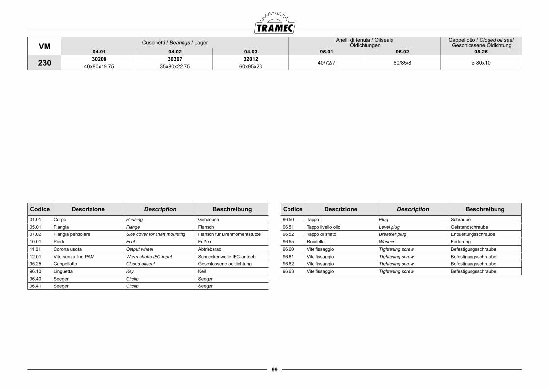
99
VM Cuscinetti / Bearings / Lager Anelli di tenuta / Oilseals Öldichtungen
Cappellotto / Closed oil seal Geschlossene Öldichtung
94.01 94.02 94.03 95.01 95.02 95.25
230 30208 30307 3201240/72/7 60/85/8 ø 80x10
40x80x19.75 35x80x22.75 60x95x23
Codice Descrizione Description Beschreibung01.01 Corpo Housing Gehaeuse05.01 Flangia Flange Flansch07.02 Flangia pendolare Side cover for shaft mounting Flansch für Drehmomentstutze10.01 Piede Foot Fußen11.01 Corona uscita Output wheel Abtriebsrad12.01 Vite senza fine PAM Worm shafts IEC-input Schneckenwelle IEC-antrieb95.25 Cappellotto Closed oilseal Geschlossene oeldichtung 96.10 Linguetta Key Keil96.40 Seeger Circlip Seeger96.41 Seeger Circlip Seeger
Codice Descrizione Description Beschreibung96.50 Tappo Plug Schraube96.51 Tappo livello olio Level plug Oelstandschraube96.52 Tappo di sfiato Breather plug Entlueftungsschraube96.55 Rondella Washer Federring96.60 Vite fissaggio TIghtening screw Befestigungsschraube96.61 Vite fissaggio TIghtening screw Befestigungsschraube96.62 Vite fissaggio TIghtening screw Befestigungsschraube96.63 Vite fissaggio TIghtening screw Befestigungsschraube

100
Die Garantie auf Herstellungsfehler dauert ein Jahr ab Rech-nungsdatum der Ware. Aufgrund Garantie unterliegt der TRA-MEC die Pflicht der Ersetzung oder Reparatur der defekten Teile, jedoch nicht die Übernahme weiterer Belastungen für di-rekte oder indirekte Schäden egal welcher Natur. Die Garantie verfällt bei Nichtbeachtung der in der betreffenden "Betriebs- und Instandhaltungsanleitung" angeführten Anweisungen und/oder falls ohne unsere vorausgehende schriftliche Genehmi-gung Reparaturen oder Änderungen vorgenommen wurden.
Die an uns zurückgesendete Ware akzeptieren wir nur wenn gebuehrenfrei geliefert.
Warranty for manufacturing defects will expire one-year the invoicing date. TRAMEC will replace or repair defective parts but will not accept any further charges for direct or indirect damages of any kind. The warranty will become null and void if the instructions given in the use and maintenance manual are not complied with or if repairs or changes are carried out without our prior written authorization.
Returned goods will be accepted only if delivered free of any charge.
La garanzia relativa a difetti di costruzione ha la durata di un anno dalla data di fatturazione delle merce. Tale garanzia comporta per la TRAMEC l’onere della sostituzione o ripara-zione delle parti difettose ma non ammette ulteriore addebi-ti per eventuali danni diretti o indiretti di qualsiasi natura. La garanzia decade nel caso in cui non siano state osservate le disposizioni riportate nel medesimo manuale di uso e manu-tenzione e/o siano state eseguite riparazioni o apportate mo-difiche senza nostro consenso scritto.
La merce di ritorno sarà da noi accettata solo se spedita franco di ogni spesa.
8.0 CONDIZIONI GENERALI DI GARANZIA 8.0 GENERAL CODITIONAL OF WARRANTY 8.0 ALLGEMEINE GARANTIEBEDINGUNGEN