manuale officina chd in inglese - manuel maría lombardini shop manual chd... · this manual...
TRANSCRIPT
SERVICE
LDW 1503 CHD
LDW 2004 CHD
LDW 2004/T CHD
3rd edition
WORK SHOPMANUAL
CHD series engines, p.no 1-5302.345
ENTE COMPILATORE TECO/ATL VISTOREVISIONE 02
DATA EMISSIONE
31-12-1989
MODELLO N°
50534
COD. LIBRO
1-5302-345
DATA
30-09-19961
ENTE COMPILATORE TECO/ATL DATA EMISSIONE
31-12-1989
MODELLO N°
50534
COD. LIBRO
1-5302-345
VISTOREVISIONE 02
DATA
30-09-19962
This manual contains very important information for the repair of LOMBARDINIwater-cooled indirect injection Diesel engines type LDW 1503, LDW 2004 and LDW2004/T: updated August 01, 1996.
INDEX
I MODEL NUMBER AND ENGINE IDENTIFICATION Page 3
II CHARACTERISTICS " 4
III MAINTENANCE-RECOMMENDED OIL TYPE-REFILLING " 5
IV TROUBLE SHOOTING " 6
V OVERALL DIMENSIONS " 7
VI DISASSEMBLY/REASSEMBLY " 10
VII TURBOCHARGER " 33
VIII LUBRICATION SYSTEM " 35
IX COOLING SYSTEM " 38
X FUEL SYSTEM " 40
XI ELECTRIC EQUIPMENT " 47
XII SETTINGS " 52
XIII STORAGE " 54
XIV TECHNICAL DATA " 56
XV TORQUE SPECIFICATIONS " 57
XVI SPECIAL TOOLS " 59
GENERAL ALPHABETICAL INDEX " 61
INTRODUCTION
ENTE COMPILATORE TECO/ATL VISTOREVISIONE 02
DATA EMISSIONE
31-12-1989
MODELLO N°
50534
COD. LIBRO
1-5302-345
DATA
30-09-19963
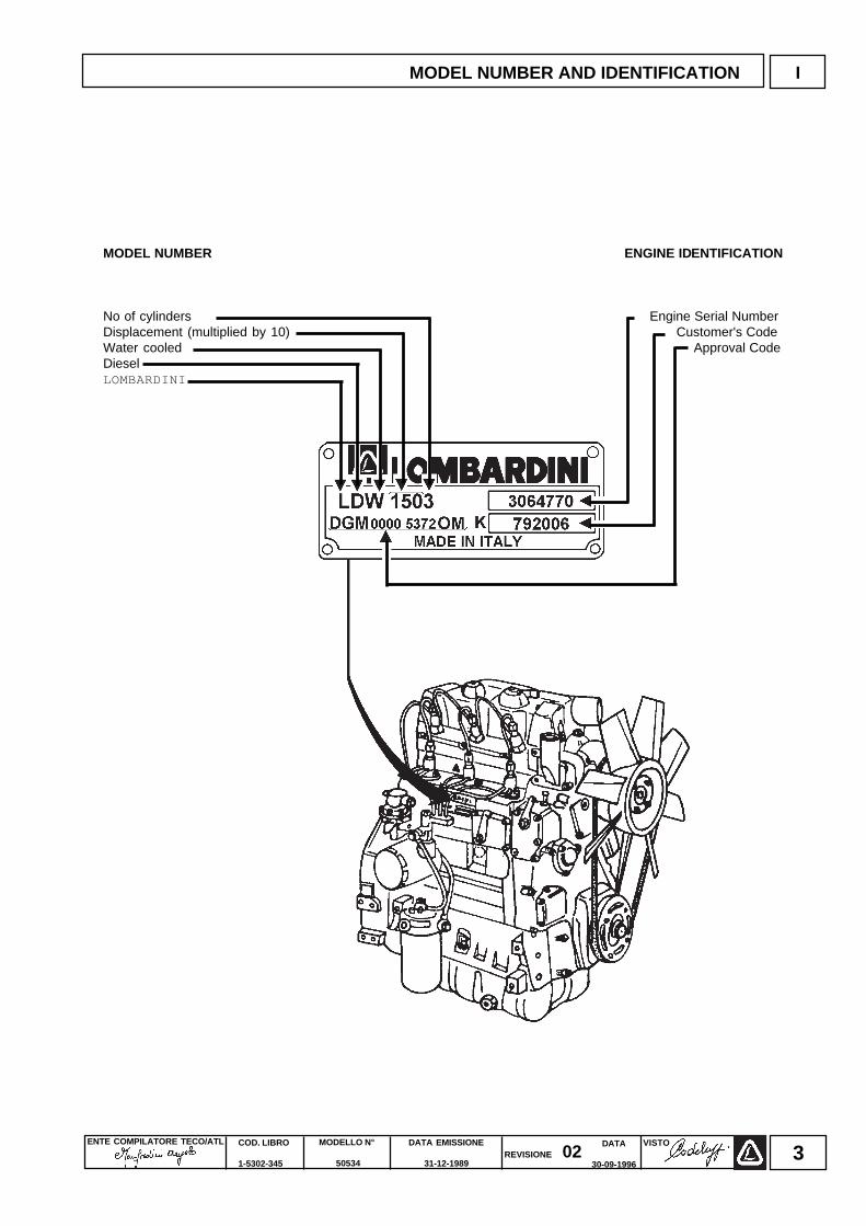
MODEL NUMBER ENGINE IDENTIFICATION
No of cylinders Engine Serial NumberDisplacement (multiplied by 10) Customer's CodeWater cooled Approval CodeDieselLOMBARDINI
MODEL NUMBER AND IDENTIFICATION I
ENTE COMPILATORE TECO/ATL DATA EMISSIONE
31-12-1989
MODELLO N°
50534
COD. LIBRO
1-5302-345
VISTOREVISIONE 02
DATA
30-09-19964
II CHARACTERISTICS
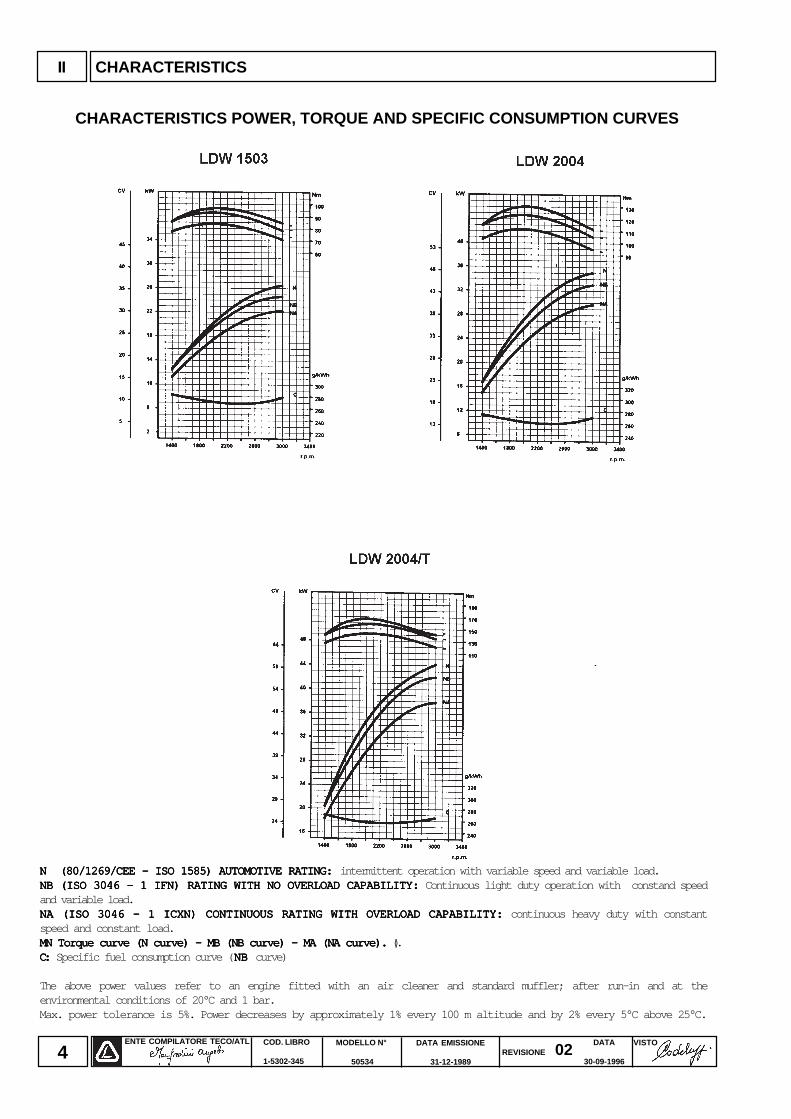
N (80/1269/CEE - ISO 1585) AUTOMOTIVE RATING: N (80/1269/CEE - ISO 1585) AUTOMOTIVE RATING: N (80/1269/CEE - ISO 1585) AUTOMOTIVE RATING: N (80/1269/CEE - ISO 1585) AUTOMOTIVE RATING: N (80/1269/CEE - ISO 1585) AUTOMOTIVE RATING: intermittent operation with variable speed and variable load.NB (ISO 3046 - 1 IFN) RATING WITH NO OVERLOAD CAPABILITY:NB (ISO 3046 - 1 IFN) RATING WITH NO OVERLOAD CAPABILITY:NB (ISO 3046 - 1 IFN) RATING WITH NO OVERLOAD CAPABILITY:NB (ISO 3046 - 1 IFN) RATING WITH NO OVERLOAD CAPABILITY:NB (ISO 3046 - 1 IFN) RATING WITH NO OVERLOAD CAPABILITY: Continuous light duty operation with constand speedand variable load.NA (ISO 3046 - 1 ICXN) CONTINUOUS RATING WITH OVERLOAD CAPABILITY:NA (ISO 3046 - 1 ICXN) CONTINUOUS RATING WITH OVERLOAD CAPABILITY:NA (ISO 3046 - 1 ICXN) CONTINUOUS RATING WITH OVERLOAD CAPABILITY:NA (ISO 3046 - 1 ICXN) CONTINUOUS RATING WITH OVERLOAD CAPABILITY:NA (ISO 3046 - 1 ICXN) CONTINUOUS RATING WITH OVERLOAD CAPABILITY: continuous heavy duty with constantspeed and constant load.MN Torque curve (N curve) - MB (NB curve) - MA (NA curve).MN Torque curve (N curve) - MB (NB curve) - MA (NA curve).MN Torque curve (N curve) - MB (NB curve) - MA (NA curve).MN Torque curve (N curve) - MB (NB curve) - MA (NA curve).MN Torque curve (N curve) - MB (NB curve) - MA (NA curve). ().C: C: C: C: C: Specific fuel consumption curve ( NB NB NB NB NB curve)
The above power values refer to an engine fitted with an air cleaner and standard muffler; after run-in and at theenvironmental conditions of 20°C and 1 bar.Max. power tolerance is 5%. Power decreases by approximately 1% every 100 m altitude and by 2% every 5°C above 25°C.
CHARACTERISTICS POWER, TORQUE AND SPECIFIC CONSUMPTION CURVES
ENTE COMPILATORE TECO/ATL VISTOREVISIONE 02
DATA EMISSIONE
31-12-1989
MODELLO N°
50534
COD. LIBRO
1-5302-345
DATA
30-09-19965
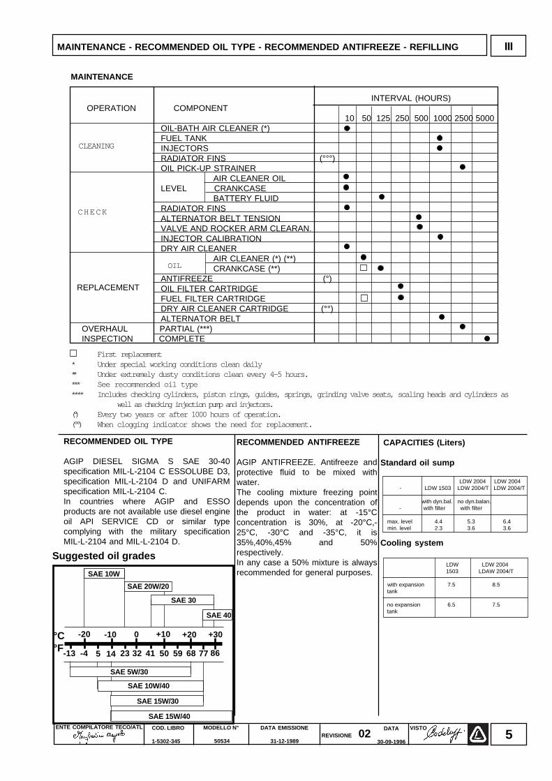
INTERVAL (HOURS) OPERATION COMPONENT
10 50 125 250 500 1000 2500 5000OIL-BATH AIR CLEANER (*)FUEL TANKINJECTORSRADIATOR FINS (°°°)OIL PICK-UP STRAINER
AIR CLEANER OILLEVEL CRANKCASE
BATTERY FLUIDRADIATOR FINSALTERNATOR BELT TENSIONVALVE AND ROCKER ARM CLEARAN.INJECTOR CALIBRATIONDRY AIR CLEANER
AIR CLEANER (*) (**)CRANKCASE (**)
ANTIFREEZE (°)OIL FILTER CARTRIDGEFUEL FILTER CARTRIDGEDRY AIR CLEANER CARTRIDGE (°°)ALTERNATOR BELT
OVERHAUL PARTIAL (***)INSPECTION COMPLETE
LDW LDW 2004 1503 LDAW 2004/T
with expansion 7.5 8.5 tank
no expansion 6.5 7.5 tank
RECOMMENDED OIL TYPE
AGIP DIESEL SIGMA S SAE 30-40specification MIL-L-2104 C ESSOLUBE D3,specification MIL-L-2104 D and UNIFARMspecification MIL-L-2104 C.In countries where AGIP and ESSOproducts are not available use diesel engineoil API SERVICE CD or similar typecomplying with the military specificationMIL-L-2104 and MIL-L-2104 D.
OIL
CAPACITIES (Liters)
Standard oil sump
LDW 2004 LDW 2004 - LDW 1503 LDW 2004/T LDW 2004/T
with dyn.bal. no dyn.balan. - with filter with filter
max. level 4.4 5.3 6.4 min. level 2.3 3.6 3.6
Cooling system
MAINTENANCE
REPLACEMENT
First replacement* Under special working conditions clean daily** Under extremely dusty conditions clean every 4-5 hours.*** See recommended oil type**** Includes checking cylinders, piston rings, guides, springs, grinding valve seats, scaling heads and cylinders as well as checking injection pump and injectors.(°) Every two years or after 1000 hours of operation.(°°) When clogging indicator shows the need for replacement.
CHECK
CLEANING
RECOMMENDED ANTIFREEZE
AGIP ANTIFREEZE. Antifreeze andprotective fluid to be mixed withwater.The cooling mixture freezing pointdepends upon the concentration ofthe product in water: at -15°Cconcentration is 30%, at -20°C,-25°C, -30°C and -35°C, it is35%,40%,45% and 50%respectively.In any case a 50% mixture is alwaysrecommended for general purposes.
SAE 5W/30
SAE 10W/40
SAE 15W/40
SAE 15W/30
-20 -10 +10 +20 +300
-13 -4 5 14 23 32 41 8650 59 68 77
SAE 40
°C°F
SAE 30
SAE 20W/20
Suggested oil grades
SAE 10W
MAINTENANCE - RECOMMENDED OIL TYPE - RECOMMENDED ANTIFREEZE - REFILLING III
ENTE COMPILATORE TECO/ATL DATA EMISSIONE
31-12-1989
MODELLO N°
50534
COD. LIBRO
1-5302-345
VISTOREVISIONE 02
DATA
30-09-19966
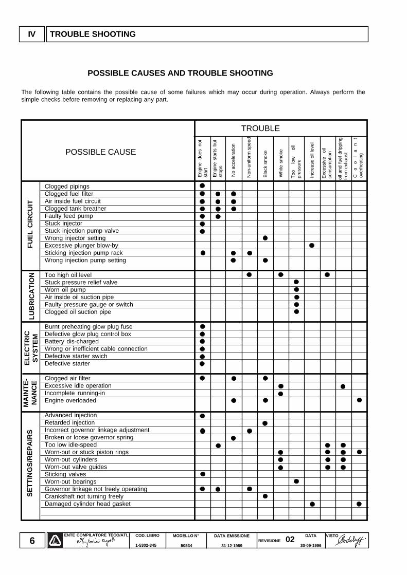
Clogged pipingsClogged fuel filterAir inside fuel circuitClogged tank breatherFaulty feed pumpStuck injectorStuck injection pump valveWrong injector settingExcessive plunger blow-bySticking injection pump rackWrong injection pump setting
Too high oil levelStuck pressure relief valveWorn oil pumpAir inside oil suction pipeFaulty pressure gauge or switchClogged oil suction pipe
Burnt preheating glow plug fuseDefective glow plug control boxBattery dis-chargedWrong or inefficient cable connectionDefective starter swichDefective starter
Clogged air filterExcessive idle operationIncomplete running-inEngine overloaded
Advanced injectionRetarded injectionIncorrect governor linkage adjustmentBroken or loose governor springToo low idle-speedWorn-out or stuck piston ringsWorn-out cylindersWorn-out valve guidesSticking valvesWorn-out bearingsGovernor linkage not freely operatingCrankshaft not turning freelyDamaged cylinder head gasket
POSSIBLE CAUSES AND TROUBLE SHOOTING
The following table contains the possible cause of some failures which may occur during operation. Always perform thesimple checks before removing or replacing any part.
TROUBLE
MA
INT
E-
NA
NC
EE
LEC
TR
ICS
YS
TE
MLU
BR
ICA
TIO
N
POSSIBLE CAUSE
IV TROUBLE SHOOTING
Eng
ine
does
no
tst
art
Eng
ine
star
ts b
utst
ops
No
acce
lera
tion
Non
-uni
form
spe
ed
Bla
ck s
mok
e
Whi
te s
mok
e
Co
ol
an
tov
erhe
atin
g
oil a
nd f
uel d
rippi
ngfr
om e
xhau
st
Exc
essi
ve
oil
cons
umpt
ion
Incr
ease
oil
leve
l
Too
lo
w
oil
pres
sure
SE
TT
ING
S/R
EP
AIR
SF
UE
L C
IRC
UIT
ENTE COMPILATORE TECO/ATL VISTOREVISIONE 02
DATA EMISSIONE
31-12-1989
MODELLO N°
50534
COD. LIBRO
1-5302-345
DATA
30-09-19967
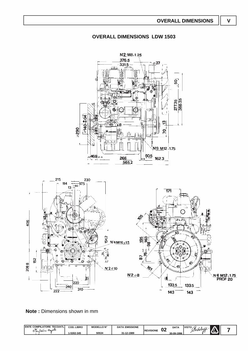
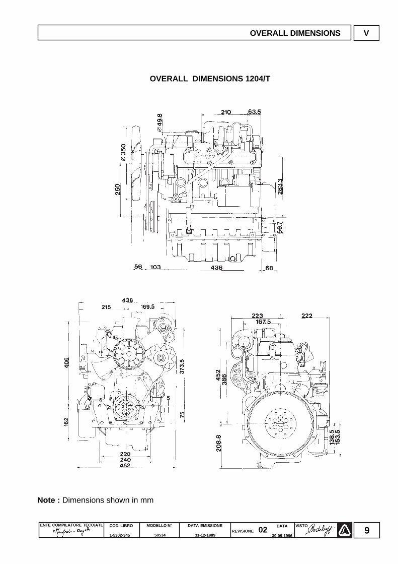
Note : Dimensions shown in mm
OVERALL DIMENSIONS V
OVERALL DIMENSIONS LDW 1503
ENTE COMPILATORE TECO/ATL DATA EMISSIONE
31-12-1989
MODELLO N°
50534
COD. LIBRO
1-5302-345
VISTOREVISIONE 02
DATA
30-09-19968
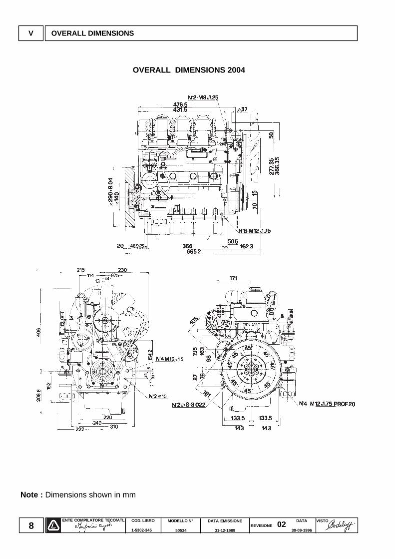
Note : Dimensions shown in mm
V OVERALL DIMENSIONS
OVERALL DIMENSIONS 2004
ENTE COMPILATORE TECO/ATL VISTOREVISIONE 02
DATA EMISSIONE
31-12-1989
MODELLO N°
50534
COD. LIBRO
1-5302-345
DATA
30-09-19969
Note : Dimensions shown in mm
OVERALL DIMENSIONS V
OVERALL DIMENSIONS 1204/T
ENTE COMPILATORE TECO/ATL DATA EMISSIONE
31-12-1989
MODELLO N°
50534
COD. LIBRO
1-5302-345
VISTOREVISIONE 02
DATA
30-09-199610
VI DISASSEMBY AND REASSEMBLY
DISASSEMBLY AND REASSEMBLY
Besides disassembly and reassembly operations this chapter alsoincludes checking and setting specifications, dimensions, repair andoperating instructions. Always use original LOMBARDINI spare partsfor repair operations.
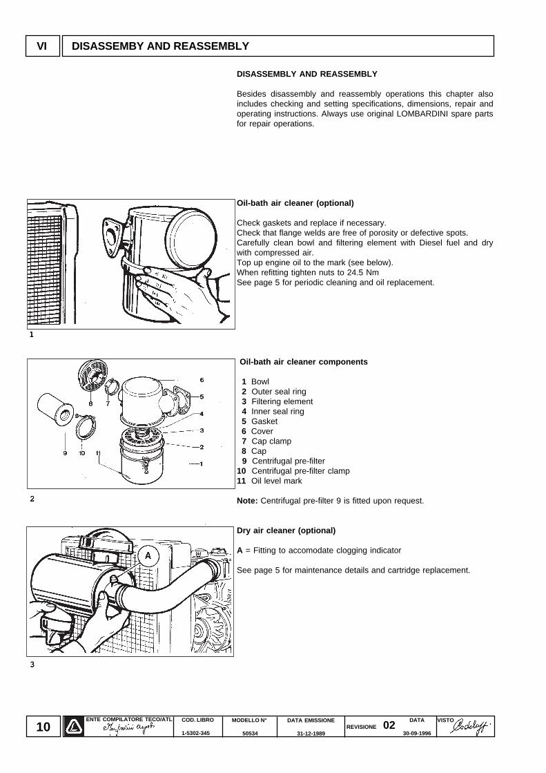
Oil-bath air cleaner (optional)
Check gaskets and replace if necessary.Check that flange welds are free of porosity or defective spots.Carefully clean bowl and filtering element with Diesel fuel and drywith compressed air.Top up engine oil to the mark (see below).When refitting tighten nuts to 24.5 NmSee page 5 for periodic cleaning and oil replacement.
Oil-bath air cleaner components
1 Bowl 2 Outer seal ring 3 Filtering element 4 Inner seal ring 5 Gasket 6 Cover 7 Cap clamp 8 Cap 9 Centrifugal pre-filter10 Centrifugal pre-filter clamp11 Oil level mark
Note: Centrifugal pre-filter 9 is fitted upon request.
Dry air cleaner (optional)
A = Fitting to accomodate clogging indicator
See page 5 for maintenance details and cartridge replacement.
11111
22222
33333
ENTE COMPILATORE TECO/ATL VISTOREVISIONE 02
DATA EMISSIONE
31-12-1989
MODELLO N°
50534
COD. LIBRO
1-5302-345
DATA
30-09-199611
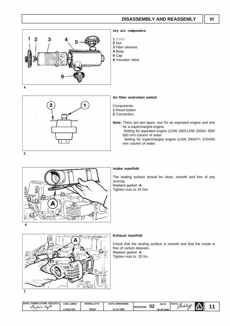
Dry air componentsDry air componentsDry air componentsDry air componentsDry air components
1 1 1 1 1 Cover2 Nut3 Filter element4 Body5 Cap6 Vacuator valve
Air filter restriction switch
Components:1 Reset button2 Connection
Note: There are two types: one for an aspirated engine and onefor a supercharged engine.
Setting for aspirated engine (LDW 1503,LDW 2004)= 600/650 mm column of water.
Setting for supercharged engine (LDW 2004/T= 370/420mm column of water.
Intake manifold
The sealing surface should be clean, smooth and free of anyscoring.Replace gasket A.Tighten nuts to 25 Nm.
Exhaust manifold
Check that the sealing surface is smooth and that the inside isfree of carbon deposits.Replace gasket A.Tighten nuts to 25 Nm.
44444
66666
DISASSEMBLY AND REASSEMLY VI
55555
7
ENTE COMPILATORE TECO/ATL DATA EMISSIONE
31-12-1989
MODELLO N°
50534
COD. LIBRO
1-5302-345
VISTOREVISIONE 02
DATA
30-09-199612
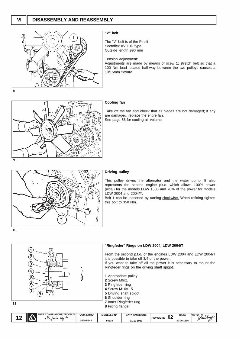
"V" belt
The "V" belt is of the PirelliSectoflex AV 10D type.Outside length 990 mm
Tension adjustment:Adjustments are made by means of scew 1; stretch belt so that a100 Nm load located half-way between the two pulleys causes a10/15mm flexure.
Cooling fan
Take off the fan and check that all blades are not damaged; if anyare damaged, replace the entire fan.See page 56 for cooling air volume.
Driving pulley
This pulley drives the alternator and the water pump. It alsorepresents the second engine p.t.o. which allows 100% power(axial) for the models LDW 1503 and 70% of the power for modelsLDW 2004 and 2004/T.Bolt 1 can be loosened by turning clockwise. When refitting tightenthis bolt to 350 Nm.
"Ringfeder" Rings on LDW 2004, LDW 2004/T
From the second p.t.o. of the engines LDW 2004 and LDW 2004/Tit is possible to take off 3/4 of the power.If you want to take off all the power it is necessary to mount theRingfeder rings on the driving shaft spigot.
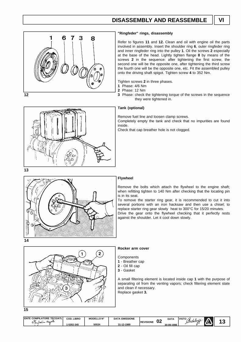
1 Appropriate pulley2 Screw M6x13 Ringfeder ring4 Screw M16x1.55 Driving shaft spigot6 Shoulder ring7 Inner Ringfeder ring8 Fixing flange
VI DISASSEMBLY AND REASSEMBLY
1111111111
1010101010
99999
88888
ENTE COMPILATORE TECO/ATL VISTOREVISIONE 02
DATA EMISSIONE
31-12-1989
MODELLO N°
50534
COD. LIBRO
1-5302-345
DATA
30-09-199613
VIDISASSEMBLY AND REASSEMBLE
15
12
"Ringfeder" rings, disassembly
Refer to figures 11 and 12. Clean and oil with engine oil the partsinvolved in assembly. Insert the shoulder ring 6, outer ringfeder ringand inner ringfeder ring into the pulley 1. Oil the screws 2 especiallyat the base of the head. Lightly tighten flange 8 by means of thescrews 2 in the sequence: after tightening the first screw, thesecond one will be the opposite one, after tightening the third screwthe fourth one will be the opposite one, etc. Fit the assembled pulleyonto the driving shaft spigot. Tighten screw 4 to 352 Nm.
Tighten screws 2 in three phases.1 Phase: 4/6 Nm2 Phase: 12 Nm3 Phase: check the tightening torque of the screws in the sequence
they were tightened in.
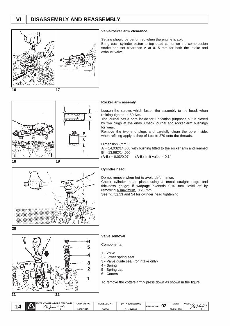
Tank (optional)
Remove fuel line and loosen clamp screws.Completely empty the tank and check that no impurities are foundinside.Check that cap breather hole is not clogged.
Flywheel
Remove the bolts which attach the flywheel to the engine shaft;when refitting tighten to 140 Nm after checking that the locating pinis in its seat.To remove the starter ring gear, it is recommended to cut it intoseveral portions with an iron hacksaw and then use a chisel; toreplace starter ring gear slowly heat to 300°C for 15/20 minutes.Drive the gear onto the flywheel checking that it perfectly restsagainst the shoulder. Let it cool down slowly.
Rocker arm cover
Components1 - Breather cap2 - Oil fill cap3 - Gasket
A small filtering element is located inside cap 1 with the purpose ofseparating oil from the venting vapors; check filtering element stateand clean if necessary.Replace gasket 3.
14
13
ENTE COMPILATORE TECO/ATL DATA EMISSIONE
31-12-1989
MODELLO N°
50534
COD. LIBRO
1-5302-345
VISTOREVISIONE 02
DATA
30-09-199614
DISASSEMBLY AND REASSEMBLYVI
21 22
16 17
18 19
20
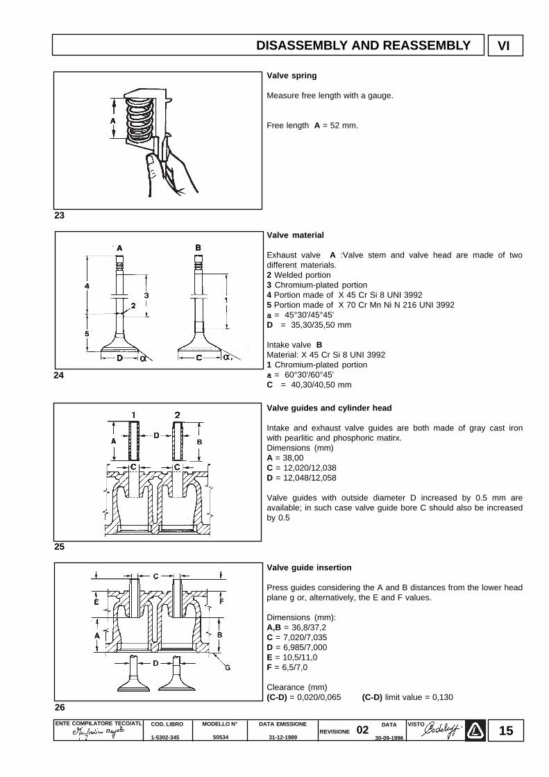
Valve/rocker arm clearance
Setting should be performed when the engine is cold.Bring each cylinder piston to top dead center on the compressionstroke and set clearance A at 0.15 mm for both the intake andexhaust valve.
Rocker arm assemly
Loosen the screws which fasten the assembly to the head; whenrefitting tighten to 50 Nm.The journal has a bore inside for lubrication purposes but is closedby two plugs at the ends. Check journal and rocker arm bushingsfor wear.Remove the two end plugs and carefully clean the bore inside;when refitting apply a drop of Loctite 270 onto the threads.
Dimension (mm):A = 14,032/14,050 with bushing fitted to the rocker arm and reamedB = 13,982/14,000(A-B ) = 0,03/0,07 (A-B ) limit value = 0,14
Cylinder head
Do not remove when hot to avoid deformation.Check cylinder head plane using a metal straight edge andthickness gauge; if warpage exceeds 0.10 mm, level off byremoving a maximum 0.20 mm.See fig. 52,53 and 54 for cylinder head tightening.
Valve removal
Components:
1 - Valve2 - Lower spring seat3 - Valve guide seal (for intake only)4 - Spring5 - Spring cap6 - Cotters
To remove the cotters firmly press down as shown in the figure.
ENTE COMPILATORE TECO/ATL VISTOREVISIONE 02
DATA EMISSIONE
31-12-1989
MODELLO N°
50534
COD. LIBRO
1-5302-345
DATA
30-09-199615
DISASSEMBLY AND REASSEMBLY VI
23
25
Valve spring
Measure free length with a gauge.
Free length A = 52 mm.
Valve material
Exhaust valve A :Valve stem and valve head are made of twodifferent materials.2 Welded portion3 Chromium-plated portion4 Portion made of X 45 Cr Si 8 UNI 39925 Portion made of X 70 Cr Mn Ni N 216 UNI 3992aaaaa = 45°30'/45°45'D = 35,30/35,50 mm
Intake valve BMaterial: X 45 Cr Si 8 UNI 39921 Chromium-plated portionaaaaa = 60°30'/60°45'C = 40,30/40,50 mm
Valve guides and cylinder head
Intake and exhaust valve guides are both made of gray cast ironwith pearlitic and phosphoric matirx.Dimensions (mm)A = 38,00C = 12,020/12,038D = 12,048/12,058
Valve guides with outside diameter D increased by 0.5 mm areavailable; in such case valve guide bore C should also be increasedby 0.5
Valve guide insertion
Press guides considering the A and B distances from the lower headplane g or, alternatively, the E and F values.
Dimensions (mm):A,B = 36,8/37,2C = 7,020/7,035D = 6,985/7,000E = 10,5/11,0F = 6,5/7,0
Clearance (mm)(C-D) = 0,020/0,065 (C-D) limit value = 0,130
24
26
ENTE COMPILATORE TECO/ATL DATA EMISSIONE
31-12-1989
MODELLO N°
50534
COD. LIBRO
1-5302-345
VISTOREVISIONE 02
DATA
30-09-199616
DISASSEMBLY AND REASSEMBLYVI
32 33
27 28
29
30 31
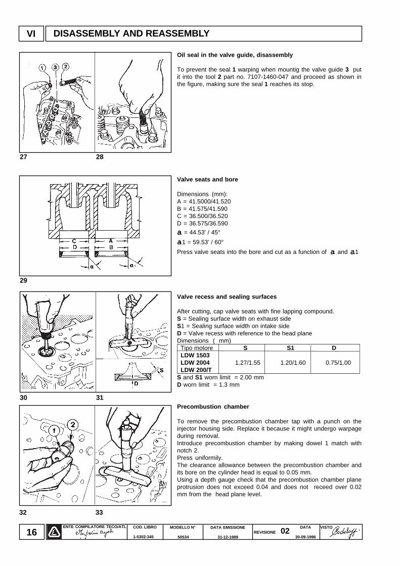
Oil seal in the valve guide, disassembly
To prevent the seal 1 warping when mountig the valve guide 3 putit into the tool 2 part no. 7107-1460-047 and proceed as shown inthe figure, making sure the seal 1 reaches its stop.
Valve seats and bore
Dimensions (mm):A = 41.5000/41.520B = 41.575/41.590C = 36.500/36.520D = 36.575/36.590
aaaaa = 44.53' / 45°
aaaaa1 = 59.53' / 60°
Press valve seats into the bore and cut as a function of a a a a a and a a a a a1
Valve recess and sealing surfaces
After cutting, cap valve seats with fine lapping compound.S = Sealing surface width on exhaust sideS1 = Sealing surface width on intake sideD = Valve recess with reference to the head planeDimensions ( mm) Tipo motore S S1 D LDW 1503 LDW 2004 1.27/1.55 1.20/1.60 0.75/1.00 LDW 200/TS and S1 worn limit = 2.00 mmD worn limit = 1.3 mm
Precombustion chamber
To remove the precombustion chamber tap with a punch on theinjector housing side. Replace it because it might undergo warpageduring removal.Introduce precombustion chamber by making dowel 1 match withnotch 2.Press uniformily.The clearance allowance between the precombustion chamber andits bore on the cylinder head is equal to 0.05 mm.Using a depth gauge check that the precombustion chamber planeprotrusion does not exceed 0.04 and does not receed over 0.02mm from the head plane level.
ENTE COMPILATORE TECO/ATL VISTOREVISIONE 02
DATA EMISSIONE
31-12-1989
MODELLO N°
50534
COD. LIBRO
1-5302-345
DATA
30-09-199617
VI
34 35
DISASSEMBLY AND REASSEMBLY
38 39
36 37
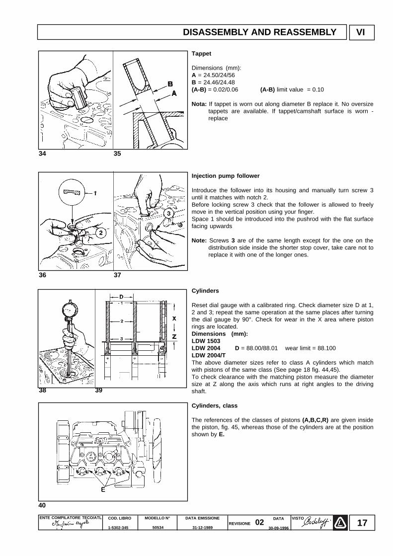
Tappet
Dimensions (mm):A = 24.50/24/56B = 24.46/24.48(A-B) = 0.02/0.06 (A-B) limit value = 0.10
Nota: If tappet is worn out along diameter B replace it. No oversizetappets are available. If tappet/camshaft surface is worn -replace
Injection pump follower
Introduce the follower into its housing and manually turn screw 3until it matches with notch 2.Before locking screw 3 check that the follower is allowed to freelymove in the vertical position using your finger.Space 1 should be introduced into the pushrod with the flat surfacefacing upwards
Note: Screws 3 are of the same length except for the one on thedistribution side inside the shorter stop cover, take care not toreplace it with one of the longer ones.
Cylinders
Reset dial gauge with a calibrated ring. Check diameter size D at 1,2 and 3; repeat the same operation at the same places after turningthe dial gauge by 90°. Check for wear in the X area where pistonrings are located.Dimensions (mm):LDW 1503LDW 2004 D = 88.00/88.01 wear limit = 88.100LDW 2004/TThe above diameter sizes refer to class A cylinders which matchwith pistons of the same class (See page 18 fig. 44,45).To check clearance with the matching piston measure the diametersize at Z along the axis which runs at right angles to the drivingshaft.
Cylinders, class
The references of the classes of pistons (A,B,C,R) are given insidethe piston, fig. 45, whereas those of the cylinders are at the positionshown by E.
40
ENTE COMPILATORE TECO/ATL DATA EMISSIONE
31-12-1989
MODELLO N°
50534
COD. LIBRO
1-5302-345
VISTOREVISIONE 02
DATA
30-09-199618
VI
41
42 43
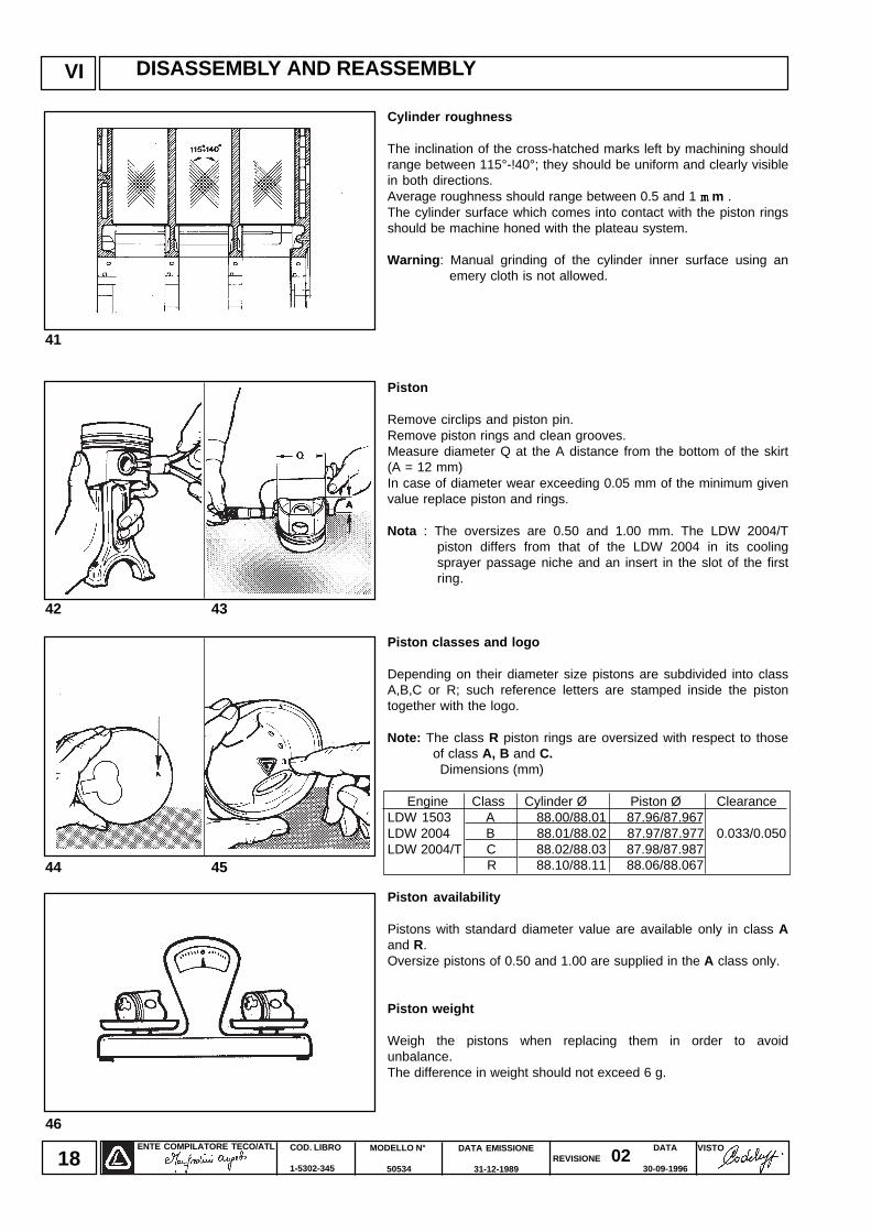
Cylinder roughness
The inclination of the cross-hatched marks left by machining shouldrange between 115°-!40°; they should be uniform and clearly visiblein both directions.Average roughness should range between 0.5 and 1 m m m m m m .The cylinder surface which comes into contact with the piston ringsshould be machine honed with the plateau system.
Warning : Manual grinding of the cylinder inner surface using anemery cloth is not allowed.
Piston
Remove circlips and piston pin.Remove piston rings and clean grooves.Measure diameter Q at the A distance from the bottom of the skirt(A = 12 mm)In case of diameter wear exceeding 0.05 mm of the minimum givenvalue replace piston and rings.
Nota : The oversizes are 0.50 and 1.00 mm. The LDW 2004/Tpiston differs from that of the LDW 2004 in its coolingsprayer passage niche and an insert in the slot of the firstring.
Piston classes and logo
Depending on their diameter size pistons are subdivided into classA,B,C or R; such reference letters are stamped inside the pistontogether with the logo.
Note: The class R piston rings are oversized with respect to thoseof class A, B and C.
Dimensions (mm)
Engine Class Cylinder Ø Piston Ø ClearanceLDW 1503 A 88.00/88.01 87.96/87.967LDW 2004 B 88.01/88.02 87.97/87.977 0.033/0.050LDW 2004/T C 88.02/88.03 87.98/87.987
R 88.10/88.11 88.06/88.067
Piston availability
Pistons with standard diameter value are available only in class Aand R.Oversize pistons of 0.50 and 1.00 are supplied in the A class only.
Piston weight
Weigh the pistons when replacing them in order to avoidunbalance.The difference in weight should not exceed 6 g.
44 45
46
DISASSEMBLY AND REASSEMBLY
ENTE COMPILATORE TECO/ATL VISTOREVISIONE 02
DATA EMISSIONE
31-12-1989
MODELLO N°
50534
COD. LIBRO
1-5302-345
DATA
30-09-199619
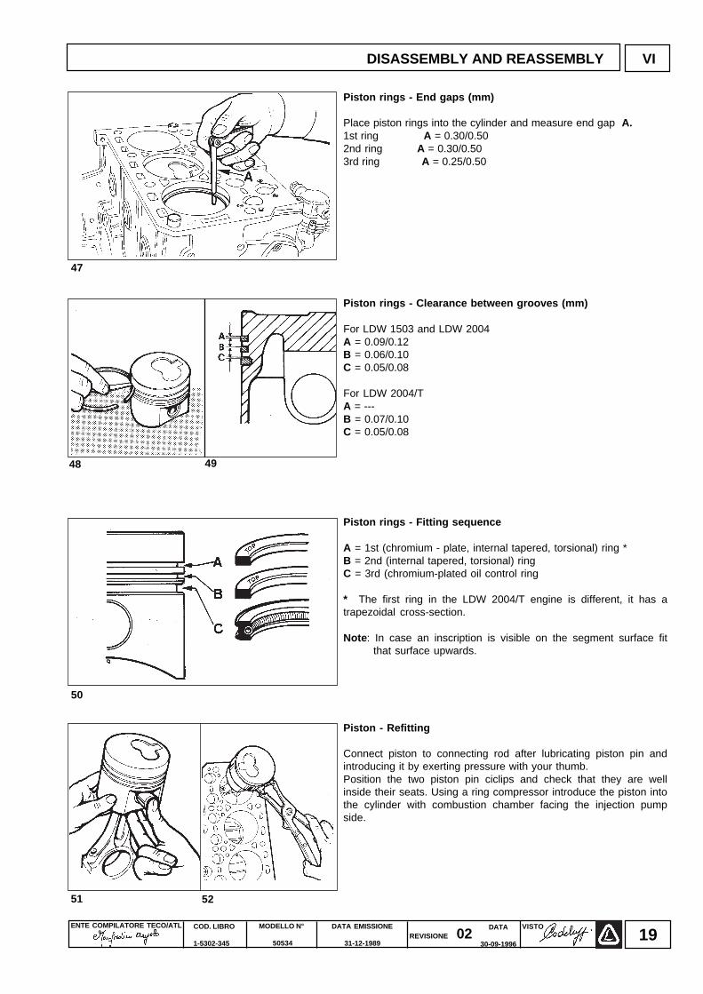
Piston rings - End gaps (mm)
Place piston rings into the cylinder and measure end gap A.1st ring A = 0.30/0.502nd ring A = 0.30/0.503rd ring A = 0.25/0.50
Piston rings - Clearance between grooves (mm)
For LDW 1503 and LDW 2004A = 0.09/0.12B = 0.06/0.10C = 0.05/0.08
For LDW 2004/TA = ---B = 0.07/0.10C = 0.05/0.08
Piston rings - Fitting sequence
A = 1st (chromium - plate, internal tapered, torsional) ring *B = 2nd (internal tapered, torsional) ringC = 3rd (chromium-plated oil control ring
* The first ring in the LDW 2004/T engine is different, it has atrapezoidal cross-section.
Note : In case an inscription is visible on the segment surface fitthat surface upwards.
Piston - Refitting
Connect piston to connecting rod after lubricating piston pin andintroducing it by exerting pressure with your thumb.Position the two piston pin ciclips and check that they are wellinside their seats. Using a ring compressor introduce the piston intothe cylinder with combustion chamber facing the injection pumpside.
47
48 49
50
5251
DISASSEMBLY AND REASSEMBLY VI
ENTE COMPILATORE TECO/ATL DATA EMISSIONE
31-12-1989
MODELLO N°
50534
COD. LIBRO
1-5302-345
VISTOREVISIONE 02
DATA
30-09-199620
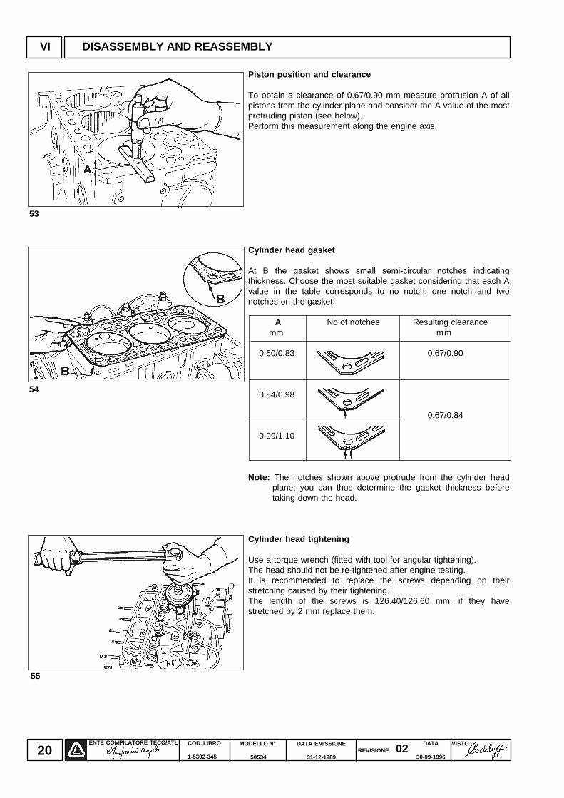
Piston position and clearance
To obtain a clearance of 0.67/0.90 mm measure protrusion A of allpistons from the cylinder plane and consider the A value of the mostprotruding piston (see below).Perform this measurement along the engine axis.
Cylinder head gasket
At B the gasket shows small semi-circular notches indicatingthickness. Choose the most suitable gasket considering that each Avalue in the table corresponds to no notch, one notch and twonotches on the gasket.
A No.of notches Resulting clearance mm mm
0.60/0.83 0.67/0.90
0.84/0.98
0.67/0.84
0.99/1.10
Note: The notches shown above protrude from the cylinder headplane; you can thus determine the gasket thickness beforetaking down the head.
Cylinder head tightening
Use a torque wrench (fitted with tool for angular tightening).The head should not be re-tightened after engine testing.It is recommended to replace the screws depending on theirstretching caused by their tightening.The length of the screws is 126.40/126.60 mm, if they havestretched by 2 mm replace them.
VI DISASSEMBLY AND REASSEMBLY
53
55
54
ENTE COMPILATORE TECO/ATL VISTOREVISIONE 02
DATA EMISSIONE
31-12-1989
MODELLO N°
50534
COD. LIBRO
1-5302-345
DATA
30-09-199621
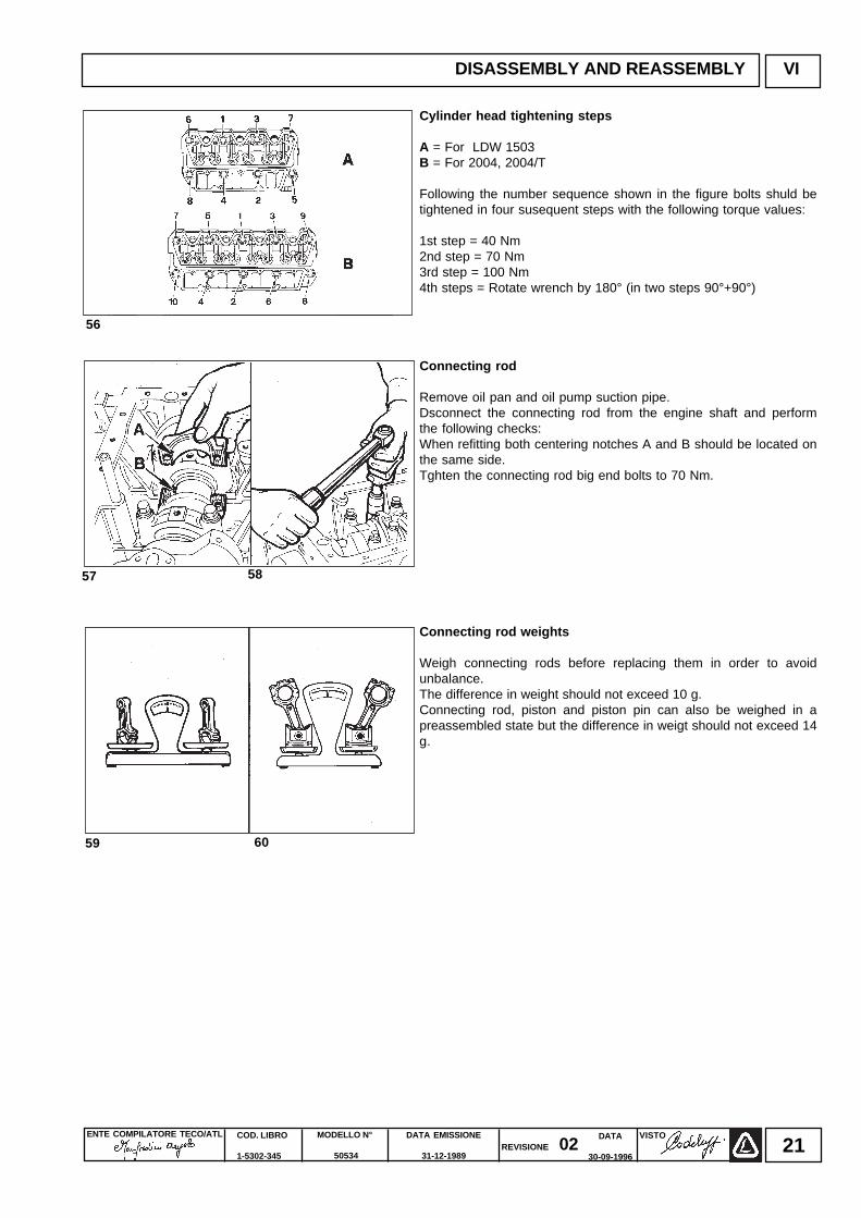
Cylinder head tightening steps
A = For LDW 1503B = For 2004, 2004/T
Following the number sequence shown in the figure bolts shuld betightened in four susequent steps with the following torque values:
1st step = 40 Nm2nd step = 70 Nm3rd step = 100 Nm4th steps = Rotate wrench by 180° (in two steps 90°+90°)
Connecting rod
Remove oil pan and oil pump suction pipe.Dsconnect the connecting rod from the engine shaft and performthe following checks:When refitting both centering notches A and B should be located onthe same side.Tghten the connecting rod big end bolts to 70 Nm.
Connecting rod weights
Weigh connecting rods before replacing them in order to avoidunbalance.The difference in weight should not exceed 10 g.Connecting rod, piston and piston pin can also be weighed in apreassembled state but the difference in weigt should not exceed 14g.
57 58
59 60
DISASSEMBLY AND REASSEMBLY VI
56
ENTE COMPILATORE TECO/ATL DATA EMISSIONE
31-12-1989
MODELLO N°
50534
COD. LIBRO
1-5302-345
VISTOREVISIONE 02
DATA
30-09-199622
61
VI DISASSEMBLY AND REASSEMBLY
62 63
64 65
66 67
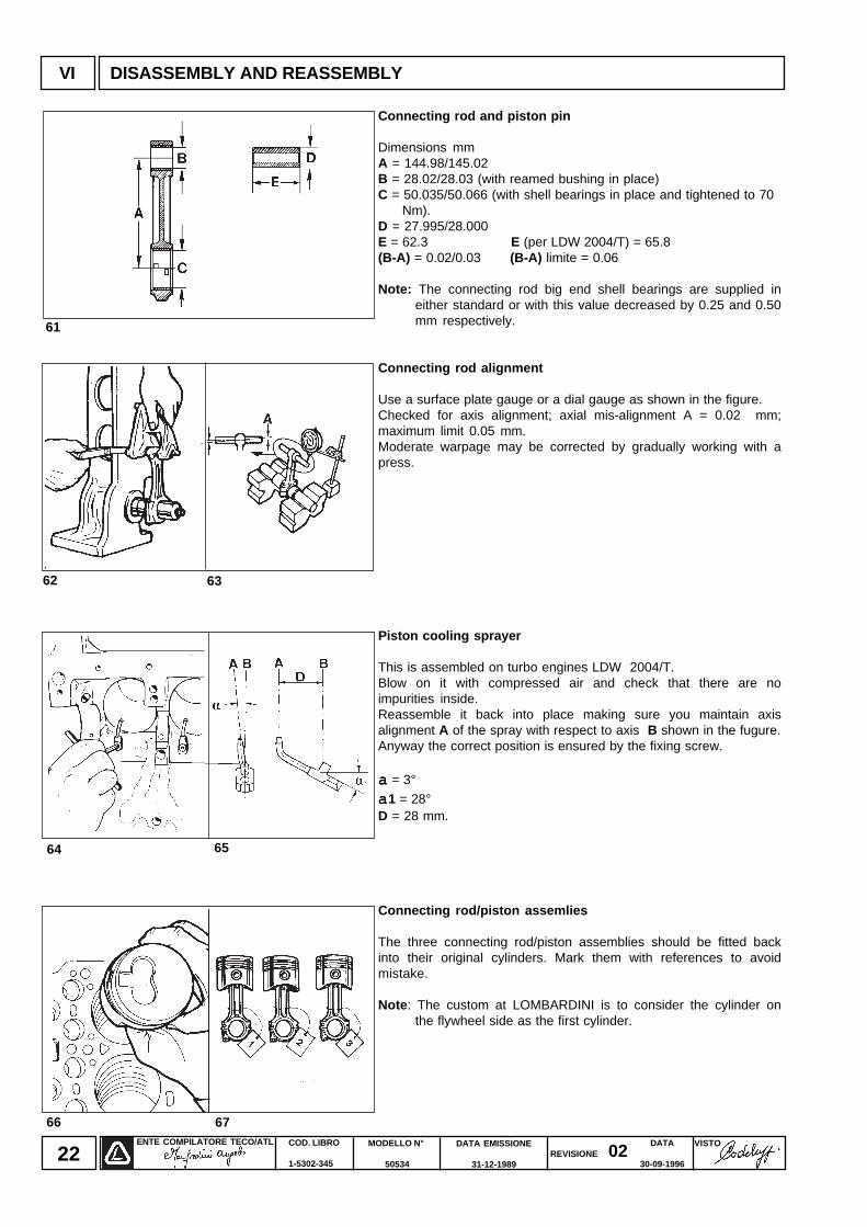
Connecting rod and piston pin
Dimensions mmA = 144.98/145.02B = 28.02/28.03 (with reamed bushing in place)C = 50.035/50.066 (with shell bearings in place and tightened to 70 Nm).D = 27.995/28.000E = 62.3 E (per LDW 2004/T) = 65.8(B-A) = 0.02/0.03 (B-A) limite = 0.06
Note: The connecting rod big end shell bearings are supplied ineither standard or with this value decreased by 0.25 and 0.50mm respectively.
Connecting rod alignment
Use a surface plate gauge or a dial gauge as shown in the figure.Checked for axis alignment; axial mis-alignment A = 0.02 mm;maximum limit 0.05 mm.Moderate warpage may be corrected by gradually working with apress.
Piston cooling sprayer
This is assembled on turbo engines LDW 2004/T.Blow on it with compressed air and check that there are noimpurities inside.Reassemble it back into place making sure you maintain axisalignment A of the spray with respect to axis B shown in the fugure.Anyway the correct position is ensured by the fixing screw.
aaaaa = 3°
aaaaa1 = 28°D = 28 mm.
Connecting rod/piston assemlies
The three connecting rod/piston assemblies should be fitted backinto their original cylinders. Mark them with references to avoidmistake.
Note : The custom at LOMBARDINI is to consider the cylinder onthe flywheel side as the first cylinder.
ENTE COMPILATORE TECO/ATL VISTOREVISIONE 02
DATA EMISSIONE
31-12-1989
MODELLO N°
50534
COD. LIBRO
1-5302-345
DATA
30-09-199623
68
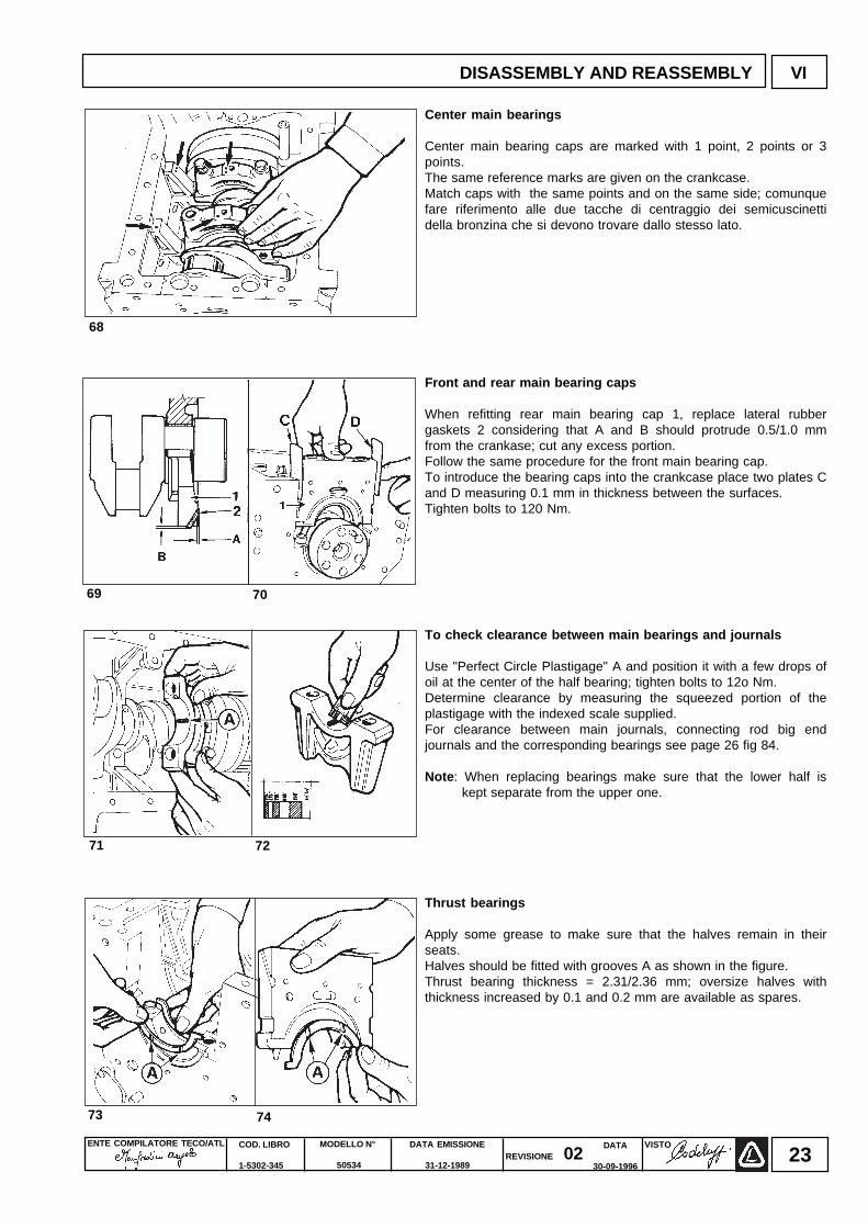
Center main bearings
Center main bearing caps are marked with 1 point, 2 points or 3points.The same reference marks are given on the crankcase.Match caps with the same points and on the same side; comunquefare riferimento alle due tacche di centraggio dei semicuscinettidella bronzina che si devono trovare dallo stesso lato.
Front and rear main bearing caps
When refitting rear main bearing cap 1, replace lateral rubbergaskets 2 considering that A and B should protrude 0.5/1.0 mmfrom the crankase; cut any excess portion.Follow the same procedure for the front main bearing cap.To introduce the bearing caps into the crankcase place two plates Cand D measuring 0.1 mm in thickness between the surfaces.Tighten bolts to 120 Nm.
To check clearance between main bearings and journals
Use "Perfect Circle Plastigage" A and position it with a few drops ofoil at the center of the half bearing; tighten bolts to 12o Nm.Determine clearance by measuring the squeezed portion of theplastigage with the indexed scale supplied.For clearance between main journals, connecting rod big endjournals and the corresponding bearings see page 26 fig 84.
Note : When replacing bearings make sure that the lower half iskept separate from the upper one.
Thrust bearings
Apply some grease to make sure that the halves remain in theirseats.Halves should be fitted with grooves A as shown in the figure.Thrust bearing thickness = 2.31/2.36 mm; oversize halves withthickness increased by 0.1 and 0.2 mm are available as spares.
7069
7271
7473
DISASSEMBLY AND REASSEMBLY VI
ENTE COMPILATORE TECO/ATL DATA EMISSIONE
31-12-1989
MODELLO N°
50534
COD. LIBRO
1-5302-345
VISTOREVISIONE 02
DATA
30-09-199624
76
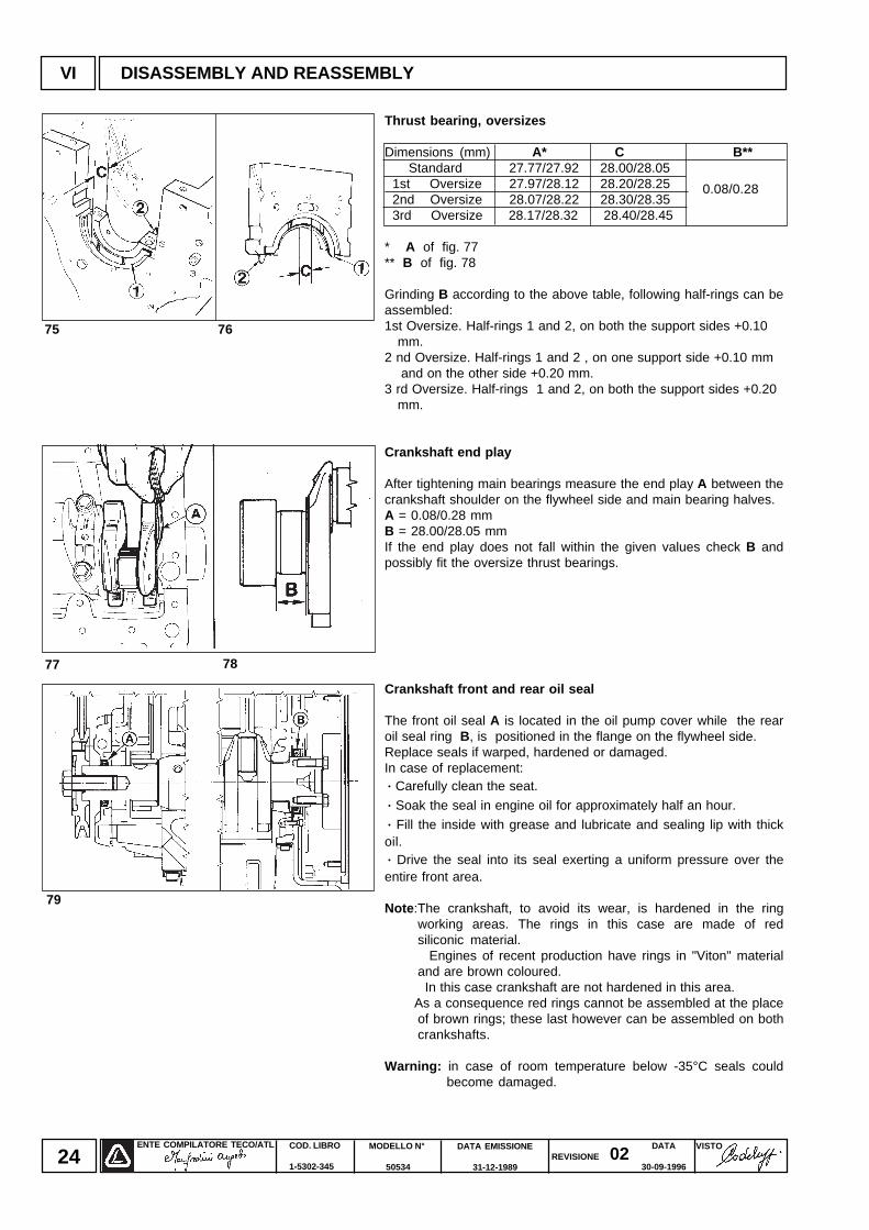
Thrust bearing, oversizes
Dimensions (mm) A* C B** Standard 27.77/27.92 28.00/28.05 1st Oversize 27.97/28.12 28.20/28.25 2nd Oversize 28.07/28.22 28.30/28.35 3rd Oversize 28.17/28.32 28.40/28.45
* A of fig. 77** B of fig. 78
Grinding B according to the above table, following half-rings can beassembled:1st Oversize. Half-rings 1 and 2, on both the support sides +0.10 mm.2 nd Oversize. Half-rings 1 and 2 , on one support side +0.10 mm and on the other side +0.20 mm.3 rd Oversize. Half-rings 1 and 2, on both the support sides +0.20 mm.
Crankshaft end play
After tightening main bearings measure the end play A between thecrankshaft shoulder on the flywheel side and main bearing halves.A = 0.08/0.28 mmB = 28.00/28.05 mmIf the end play does not fall within the given values check B andpossibly fit the oversize thrust bearings.
Crankshaft front and rear oil seal
The front oil seal A is located in the oil pump cover while the rearoil seal ring B, is positioned in the flange on the flywheel side.Replace seals if warped, hardened or damaged.In case of replacement:· Carefully clean the seat.
· Soak the seal in engine oil for approximately half an hour.
· Fill the inside with grease and lubricate and sealing lip with thickoil.· Drive the seal into its seal exerting a uniform pressure over theentire front area.
Note :The crankshaft, to avoid its wear, is hardened in the ringworking areas. The rings in this case are made of redsiliconic material.
Engines of recent production have rings in "Viton" materialand are brown coloured.
In this case crankshaft are not hardened in this area. As a consequence red rings cannot be assembled at the place
of brown rings; these last however can be assembled on bothcrankshafts.
Warning: in case of room temperature below -35°C seals couldbecome damaged.
0.08/0.28
77 78
79
75
VI DISASSEMBLY AND REASSEMBLY
ENTE COMPILATORE TECO/ATL VISTOREVISIONE 02
DATA EMISSIONE
31-12-1989
MODELLO N°
50534
COD. LIBRO
1-5302-345
DATA
30-09-199625
80
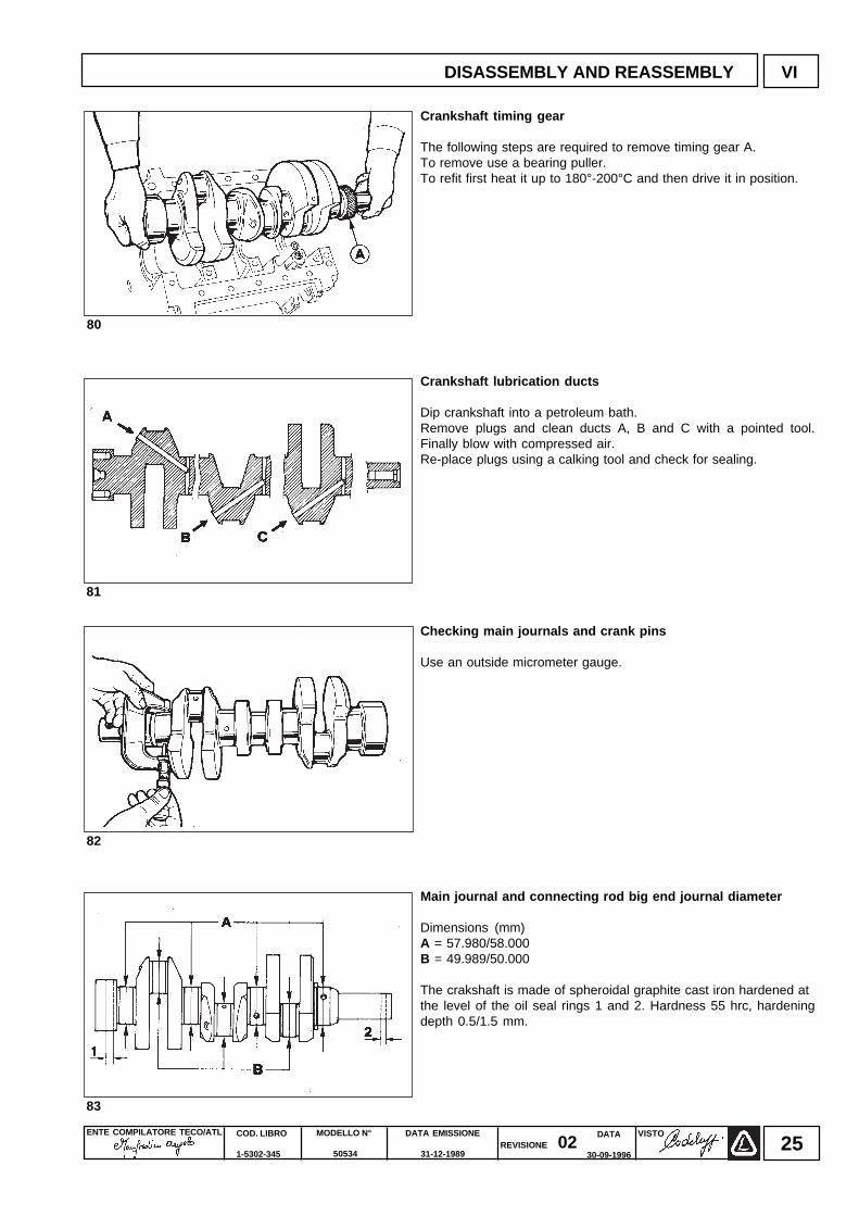
Crankshaft timing gear
The following steps are required to remove timing gear A.To remove use a bearing puller.To refit first heat it up to 180°-200°C and then drive it in position.
Crankshaft lubrication ducts
Dip crankshaft into a petroleum bath.Remove plugs and clean ducts A, B and C with a pointed tool.Finally blow with compressed air.Re-place plugs using a calking tool and check for sealing.
Checking main journals and crank pins
Use an outside micrometer gauge.
Main journal and connecting rod big end journal diameter
Dimensions (mm)A = 57.980/58.000B = 49.989/50.000
The crakshaft is made of spheroidal graphite cast iron hardened atthe level of the oil seal rings 1 and 2. Hardness 55 hrc, hardeningdepth 0.5/1.5 mm.
81
82
83
DISASSEMBLY AND REASSEMBLY VI
ENTE COMPILATORE TECO/ATL DATA EMISSIONE
31-12-1989
MODELLO N°
50534
COD. LIBRO
1-5302-345
VISTOREVISIONE 02
DATA
30-09-199626
VI DISASSEMBLY AND REASSEMBLY
84
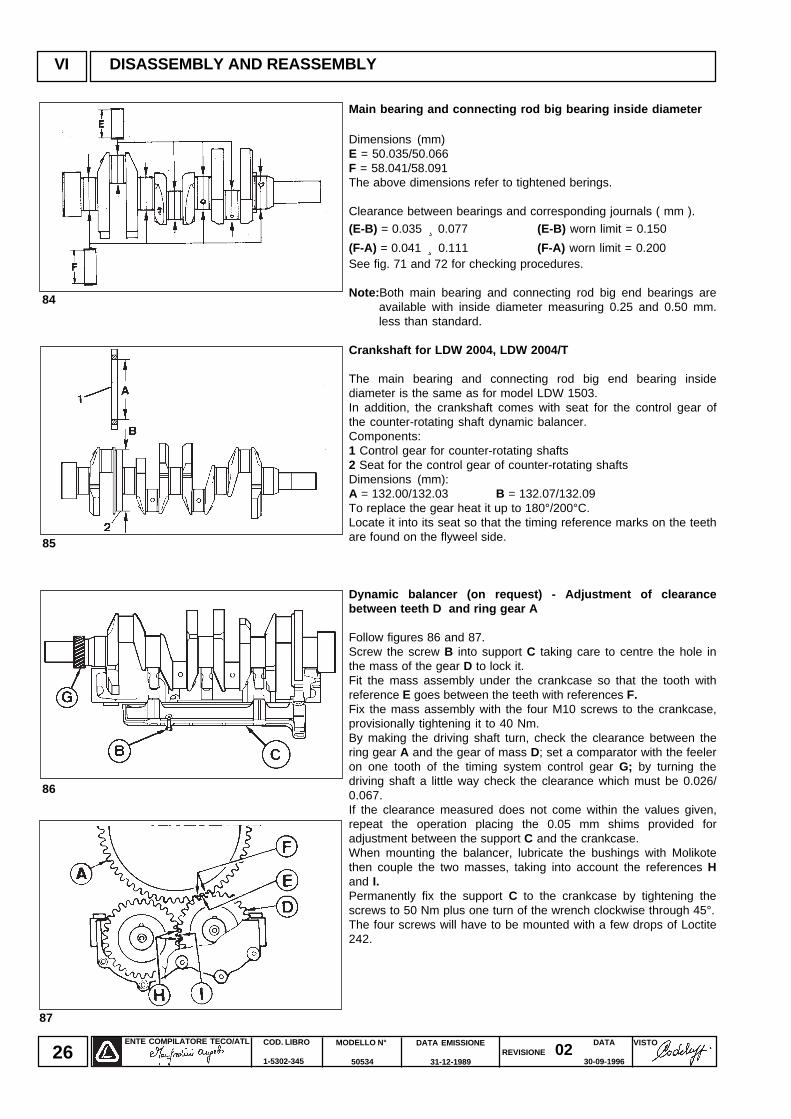
Main bearing and connecting rod big bearing inside diameter
Dimensions (mm)E = 50.035/50.066F = 58.041/58.091The above dimensions refer to tightened berings.
Clearance between bearings and corresponding journals ( mm ).
(E-B) = 0.035 ¸ 0.077 (E-B) worn limit = 0.150
(F-A) = 0.041 ̧ 0.111 (F-A) worn limit = 0.200See fig. 71 and 72 for checking procedures.
Note: Both main bearing and connecting rod big end bearings areavailable with inside diameter measuring 0.25 and 0.50 mm.less than standard.
Crankshaft for LDW 2004, LDW 2004/T
The main bearing and connecting rod big end bearing insidediameter is the same as for model LDW 1503.In addition, the crankshaft comes with seat for the control gear ofthe counter-rotating shaft dynamic balancer.Components:1 Control gear for counter-rotating shafts2 Seat for the control gear of counter-rotating shaftsDimensions (mm):A = 132.00/132.03 B = 132.07/132.09To replace the gear heat it up to 180°/200°C.Locate it into its seat so that the timing reference marks on the teethare found on the flyweel side.
Dynamic balancer (on request) - Adjustment of clearancebetween teeth D and ring gear A
Follow figures 86 and 87.Screw the screw B into support C taking care to centre the hole inthe mass of the gear D to lock it.Fit the mass assembly under the crankcase so that the tooth withreference E goes between the teeth with references F.Fix the mass assembly with the four M10 screws to the crankcase,provisionally tightening it to 40 Nm.By making the driving shaft turn, check the clearance between thering gear A and the gear of mass D; set a comparator with the feeleron one tooth of the timing system control gear G; by turning thedriving shaft a little way check the clearance which must be 0.026/0.067.If the clearance measured does not come within the values given,repeat the operation placing the 0.05 mm shims provided foradjustment between the support C and the crankcase.When mounting the balancer, lubricate the bushings with Molikotethen couple the two masses, taking into account the references Hand I.Permanently fix the support C to the crankcase by tightening thescrews to 50 Nm plus one turn of the wrench clockwise through 45°.The four screws will have to be mounted with a few drops of Loctite242.
85
86
87
ENTE COMPILATORE TECO/ATL VISTOREVISIONE 02
DATA EMISSIONE
31-12-1989
MODELLO N°
50534
COD. LIBRO
1-5302-345
DATA
30-09-199627
8988
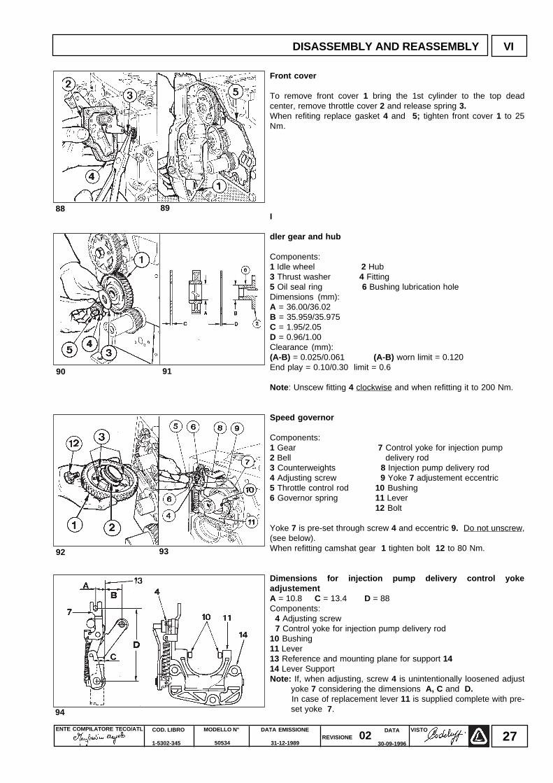
Front cover
To remove front cover 1 bring the 1st cylinder to the top deadcenter, remove throttle cover 2 and release spring 3.When refiting replace gasket 4 and 5; tighten front cover 1 to 25Nm.
I
dler gear and hub
Components:1 Idle wheel 2 Hub3 Thrust washer 4 Fitting5 Oil seal ring 6 Bushing lubrication holeDimensions (mm):A = 36.00/36.02B = 35.959/35.975C = 1.95/2.05D = 0.96/1.00Clearance (mm):(A-B) = 0.025/0.061 (A-B) worn limit = 0.120End play = 0.10/0.30 limit = 0.6
Note : Unscew fitting 4 clockwise and when refitting it to 200 Nm.
Speed governor
Components:1 Gear 7 Control yoke for injection pump2 Bell delivery rod3 Counterweights 8 Injection pump delivery rod4 Adjusting screw 9 Yoke 7 adjustement eccentric5 Throttle control rod 10 Bushing6 Governor spring 11 Lever
12 Bolt
Yoke 7 is pre-set through screw 4 and eccentric 9. Do not unscrew,(see below).When refitting camshat gear 1 tighten bolt 12 to 80 Nm.
Dimensions for injection pump delivery control yokeadjustementA = 10.8 C = 13.4 D = 88Components: 4 Adjusting screw 7 Control yoke for injection pump delivery rod10 Bushing11 Lever13 Reference and mounting plane for support 1414 Lever SupportNote: If, when adjusting, screw 4 is unintentionally loosened adjust
yoke 7 considering the dimensions A, C and D. In case of replacement lever 11 is supplied complete with pre-
set yoke 7.
9190
9392
94
DISASSEMBLY AND REASSEMBLY VI
ENTE COMPILATORE TECO/ATL DATA EMISSIONE
31-12-1989
MODELLO N°
50534
COD. LIBRO
1-5302-345
VISTOREVISIONE 02
DATA
30-09-199628
VI DISASSEMBLY AND REASSEMBLY
95
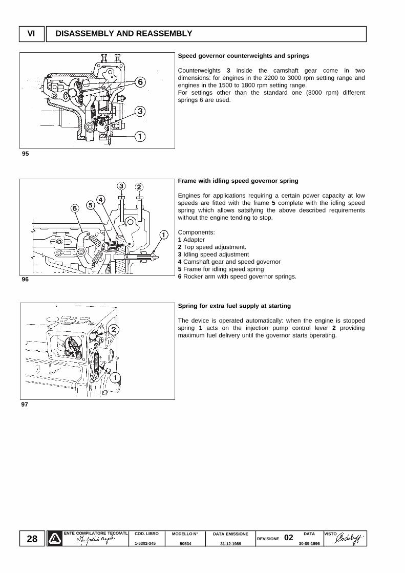
Speed governor counterweights and springs
Counterweights 3 inside the camshaft gear come in twodimensions: for engines in the 2200 to 3000 rpm setting range andengines in the 1500 to 1800 rpm setting range.For settings other than the standard one (3000 rpm) differentsprings 6 are used.
Frame with idling speed governor spring
Engines for applications requiring a certain power capacity at lowspeeds are fitted with the frame 5 complete with the idling speedspring which allows satsifying the above described requirementswithout the engine tending to stop.
Components:1 Adapter2 Top speed adjustment.3 Idling speed adjustment4 Camshaft gear and speed governor5 Frame for idling speed spring6 Rocker arm with speed governor springs.
Spring for extra fuel supply at starting
The device is operated automatically: when the engine is stoppedspring 1 acts on the injection pump control lever 2 providingmaximum fuel delivery until the governor starts operating.
96
97
ENTE COMPILATORE TECO/ATL VISTOREVISIONE 02
DATA EMISSIONE
31-12-1989
MODELLO N°
50534
COD. LIBRO
1-5302-345
DATA
30-09-199629
98
99
100
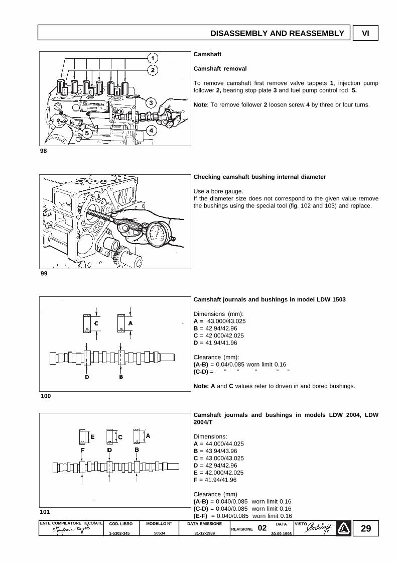
Camshaft
Camshaft removal
To remove camshaft first remove valve tappets 1, injection pumpfollower 2, bearing stop plate 3 and fuel pump control rod 5.
Note : To remove follower 2 loosen screw 4 by three or four turns.
Checking camshaft bushing internal diameter
Use a bore gauge.If the diameter size does not correspond to the given value removethe bushings using the special tool (fig. 102 and 103) and replace.
Camshaft journals and bushings in model LDW 1503
Dimensions (mm):A = 43.000/43.025B = 42.94/42.96C = 42.000/42.025D = 41.94/41.96
Clearance (mm):(A-B) = 0.04/0.085 worn limit 0.16(C-D) = " " " " "
Note: A and C values refer to driven in and bored bushings.
Camshaft journals and bushings in models LDW 2004, LDW2004/T
Dimensions:A = 44.000/44.025B = 43.94/43.96C = 43.000/43.025D = 42.94/42.96E = 42.000/42.025F = 41.94/41.96
Clearance (mm)(A-B) = 0.040/0.085 worn limit 0.16(C-D) = 0.040/0.085 worn limit 0.16(E-F) = 0.040/0.085 worn limit 0.16
101
DISASSEMBLY AND REASSEMBLY VI
ENTE COMPILATORE TECO/ATL DATA EMISSIONE
31-12-1989
MODELLO N°
50534
COD. LIBRO
1-5302-345
VISTOREVISIONE 02
DATA
30-09-199630
VI DISASSEMBLY AND REASSEMBLY
103
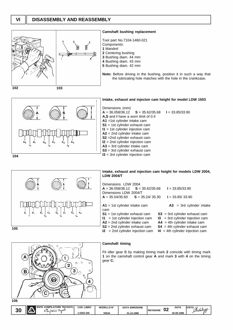
Camshaft bushing replacement
Tool part No.7104-1460-021Components:1 Mandrel2 Centering bushing3 Bushing diam. 44 mm4 Bushing diam. 43 mm5 Bushing diam. 42 mm
Note: Before driving in the bushing, position it in such a way thatthe lubricating hole maiches with the hole in the crankcase.
Intake, exhaust and injecton cam height for model LDW 1503
Dimensions (mm)A = 36.058/36.12 S = 35.62/35.68 I = 33.85/33.90A,S and I have a worn limit of 0.4A1 =1st cylinder intake camS1 = 1st cylinder exhaust camI1 = 1st cylinder injection camA2 = 2nd cylinder intake camS2 =2nd cylinder exhaust camI2 = 2nd cylinder injection camA3 = 3rd cylinder intake camS3 = 3rd cylinder exhaust camI3 = 3rd cylinder injection cam
Intake, exhaust and injection cam height for models LDW 2004,LDW 2004/T
Dimensions LDW 2004A = 36.058/36.12 S = 35.62/35.68 I = 33.85/33.90Dimensions LDW 2004/TA = 35.54/35.60 S = 35.24/ 35.30 I = 33.85/ 33.90
A1 = 1st cylinder intake cam A3 = 3rd cylinder intakecamS1 = 1st cylinder exhaust cam S3 = 3rd cylinder exhaust camI1 = 1st cylinder injection cam I3 = 3rd cylinder injection camA2 = 2nd cylinder intake cam A4 = 4th cylinder intake camS2 = 2nd cylinder exhaust cam S4 = 4th cylinder exhaust camI2 = 2nd cylinder injection cam I4 = 4th cylinder injection cam
Camshaft timing
Fit idler gear B by making timing mark 2 coincide with timing mark1 on the camshaft control gear A and mark 3 with 4 on the timinggear C.
104
102
105
106
ENTE COMPILATORE TECO/ATL VISTOREVISIONE 02
DATA EMISSIONE
31-12-1989
MODELLO N°
50534
COD. LIBRO
1-5302-345
DATA
30-09-199631
107
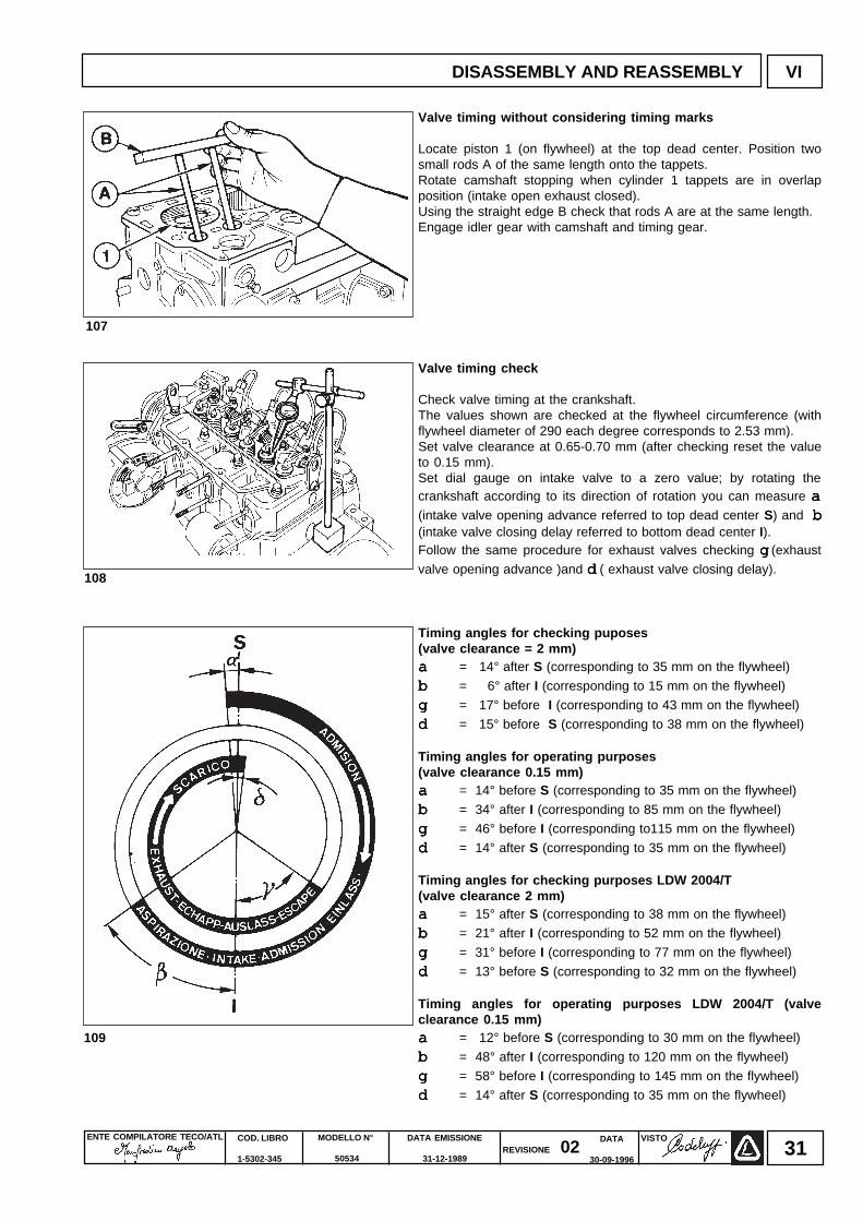
Valve timing without considering timing marks
Locate piston 1 (on flywheel) at the top dead center. Position twosmall rods A of the same length onto the tappets.Rotate camshaft stopping when cylinder 1 tappets are in overlapposition (intake open exhaust closed).Using the straight edge B check that rods A are at the same length.Engage idler gear with camshaft and timing gear.
Valve timing check
Check valve timing at the crankshaft.The values shown are checked at the flywheel circumference (withflywheel diameter of 290 each degree corresponds to 2.53 mm).Set valve clearance at 0.65-0.70 mm (after checking reset the valueto 0.15 mm).Set dial gauge on intake valve to a zero value; by rotating thecrankshaft according to its direction of rotation you can measure aaaaa(intake valve opening advance referred to top dead center S) and bbbbb(intake valve closing delay referred to bottom dead center I).Follow the same procedure for exhaust valves checking ggggg (exhaust
valve opening advance )and d d d d d ( exhaust valve closing delay).
Timing angles for checking puposes(valve clearance = 2 mm)aaaaa = 14° after S (corresponding to 35 mm on the flywheel)
bbbbb = 6° after I (corresponding to 15 mm on the flywheel)
ggggg = 17° before I (corresponding to 43 mm on the flywheel)
ddddd = 15° before S (corresponding to 38 mm on the flywheel)
Timing angles for operating purposes(valve clearance 0.15 mm)aaaaa = 14° before S (corresponding to 35 mm on the flywheel)
bbbbb = 34° after I (corresponding to 85 mm on the flywheel)
ggggg = 46° before I (corresponding to115 mm on the flywheel)
ddddd = 14° after S (corresponding to 35 mm on the flywheel)
Timing angles for checking purposes LDW 2004/T(valve clearance 2 mm)aaaaa = 15° after S (corresponding to 38 mm on the flywheel)
bbbbb = 21° after I (corresponding to 52 mm on the flywheel)
ggggg = 31° before I (corresponding to 77 mm on the flywheel)
ddddd = 13° before S (corresponding to 32 mm on the flywheel)
Timing angles for operating purposes LDW 2004/T (valveclearance 0.15 mm)aaaaa = 12° before S (corresponding to 30 mm on the flywheel)
bbbbb = 48° after I (corresponding to 120 mm on the flywheel)
ggggg = 58° before I (corresponding to 145 mm on the flywheel)
ddddd = 14° after S (corresponding to 35 mm on the flywheel)
108
109
DISASSEMBLY AND REASSEMBLY VI
ENTE COMPILATORE TECO/ATL DATA EMISSIONE
31-12-1989
MODELLO N°
50534
COD. LIBRO
1-5302-345
VISTOREVISIONE 02
DATA
30-09-199632
110
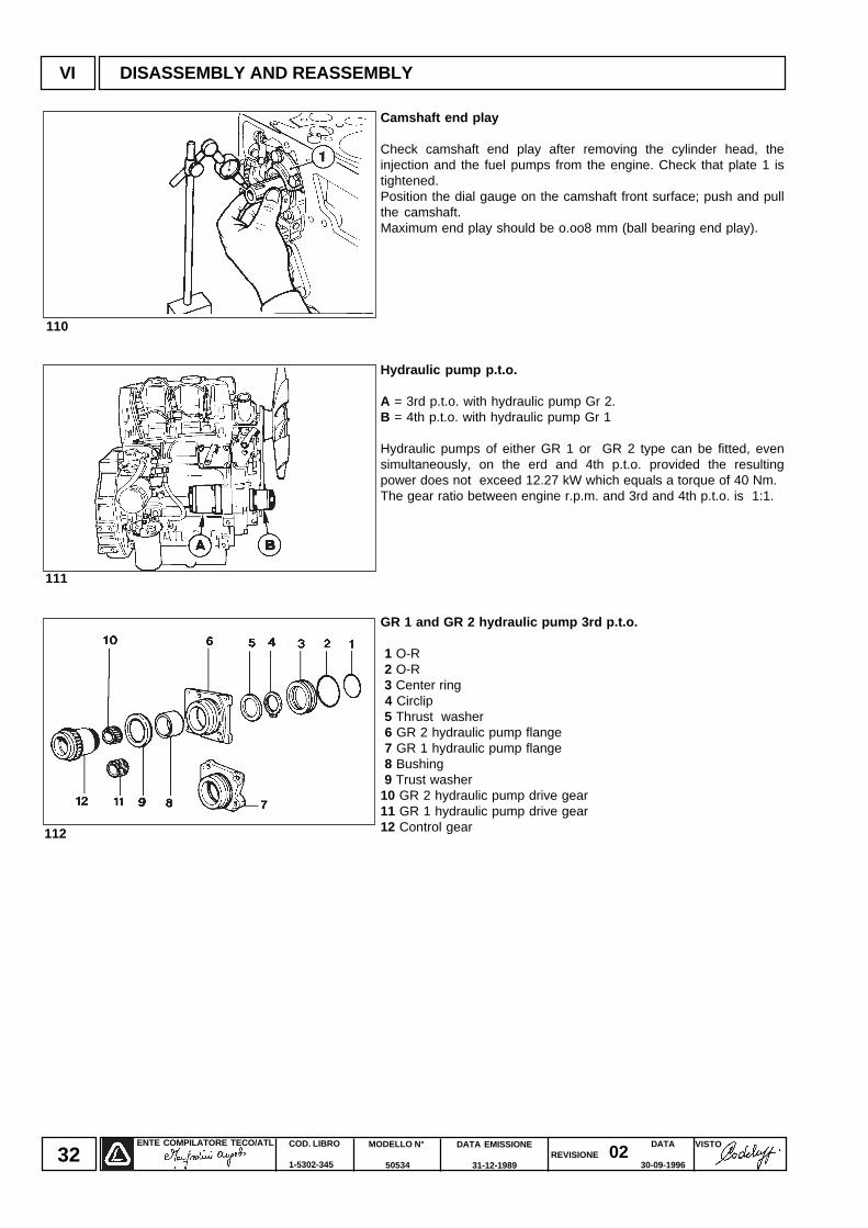
Camshaft end play
Check camshaft end play after removing the cylinder head, theinjection and the fuel pumps from the engine. Check that plate 1 istightened.Position the dial gauge on the camshaft front surface; push and pullthe camshaft.Maximum end play should be o.oo8 mm (ball bearing end play).
Hydraulic pump p.t.o.
A = 3rd p.t.o. with hydraulic pump Gr 2.B = 4th p.t.o. with hydraulic pump Gr 1
Hydraulic pumps of either GR 1 or GR 2 type can be fitted, evensimultaneously, on the erd and 4th p.t.o. provided the resultingpower does not exceed 12.27 kW which equals a torque of 40 Nm.The gear ratio between engine r.p.m. and 3rd and 4th p.t.o. is 1:1.
GR 1 and GR 2 hydraulic pump 3rd p.t.o.
1 O-R 2 O-R 3 Center ring 4 Circlip 5 Thrust washer 6 GR 2 hydraulic pump flange 7 GR 1 hydraulic pump flange 8 Bushing 9 Trust washer10 GR 2 hydraulic pump drive gear11 GR 1 hydraulic pump drive gear12 Control gear
111
112
VI DISASSEMBLY AND REASSEMBLY
ENTE COMPILATORE TECO/ATL VISTOREVISIONE 02
DATA EMISSIONE
31-12-1989
MODELLO N°
50534
COD. LIBRO
1-5302-345
DATA
30-09-199633
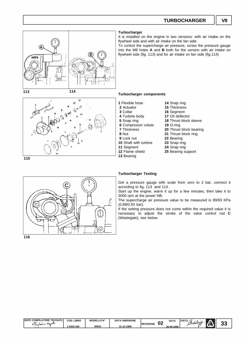
TurbochargerIt is installed on the engine in two versions: with air intake on theflywheel side and with air intake on the fan side.To control the supercharge air pressure, screw the pressure gaugeinto the M8 holes A and B both for the version with air intake onflywheel side (fig. 113) and for air intake on fan side (fig.114)
Turbocharger components
1 Flexible hose 14 Snap ring 2 Actuator 15 Thickness 3 Collar 16 Segment 4 Turbine body 17 Oil deflector 5 Snap ring 18 Thrust block sleeve 6 Compressor volute 19 O-ring 7 Thickness 20 Thrust block bearing 8 Nut 21 Thrust block ring 9 Lock nut 22 Bearing10 Shaft with turbine 23 Snap ring11 Segment 24 Snap ring12 Flame shield 25 Bearing support13 Bearing
Turbocharger Testing
Get a pressure gauge with scale from zero to 2 bar, connect itaccording to fig, 113 and 114.Start up the engine, warm it up for a few minutes, then take it to3000 rpm at the power NB.The supercharge air pressure value to be measured is 89/93 KPa(0.89/0.93 bar).If the setting pressure does not come within the required value it isnecessary to adjust the stroke of the valve control rod C(Wastegate), see below.
113 114
116
115
TURBOCHARGER VII
ENTE COMPILATORE TECO/ATL DATA EMISSIONE
31-12-1989
MODELLO N°
50534
COD. LIBRO
1-5302-345
VISTOREVISIONE 02
DATA
30-09-199634
VII TURBOCHARGER
117
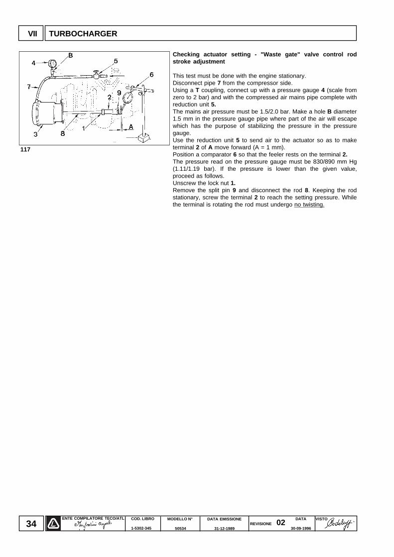
Checking actuator setting - "Waste gate" valve control rodstroke adjustment
This test must be done with the engine stationary.Disconnect pipe 7 from the compressor side.Using a T coupling, connect up with a pressure gauge 4 (scale fromzero to 2 bar) and with the compressed air mains pipe complete withreduction unit 5.The mains air pressure must be 1.5/2.0 bar. Make a hole B diameter1.5 mm in the pressure gauge pipe where part of the air will escapewhich has the purpose of stabilizing the pressure in the pressuregauge.Use the reduction unit 5 to send air to the actuator so as to maketerminal 2 of A move forward (A = 1 mm).Position a comparator 6 so that the feeler rests on the terminal 2.The pressure read on the pressure gauge must be 830/890 mm Hg(1.11/1.19 bar). If the pressure is lower than the given value,proceed as follows.Unscrew the lock nut 1.Remove the split pin 9 and disconnect the rod 8. Keeping the rodstationary, screw the terminal 2 to reach the setting pressure. Whilethe terminal is rotating the rod must undergo no twisting.
ENTE COMPILATORE TECO/ATL VISTOREVISIONE 02
DATA EMISSIONE
31-12-1989
MODELLO N°
50534
COD. LIBRO
1-5302-345
DATA
30-09-199635
LUBRICATION SYSTEM VIII
118
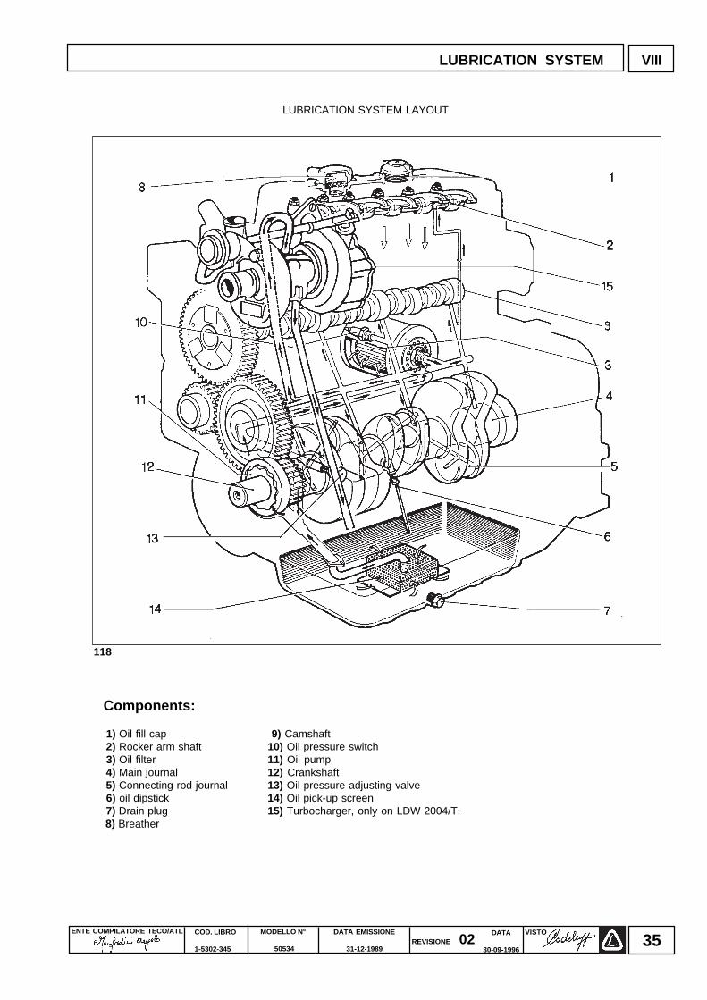
LUBRICATION SYSTEM LAYOUT
Components:
1) Oil fill cap 9) Camshaft 2) Rocker arm shaft 10) Oil pressure switch 3) Oil filter 11) Oil pump 4) Main journal 12) Crankshaft 5) Connecting rod journal 13) Oil pressure adjusting valve 6) oil dipstick 14) Oil pick-up screen 7) Drain plug 15) Turbocharger, only on LDW 2004/T. 8) Breather
ENTE COMPILATORE TECO/ATL DATA EMISSIONE
31-12-1989
MODELLO N°
50534
COD. LIBRO
1-5302-345
VISTOREVISIONE 02
DATA
30-09-199636
VIII LUBRICATION SYSTEM
120119
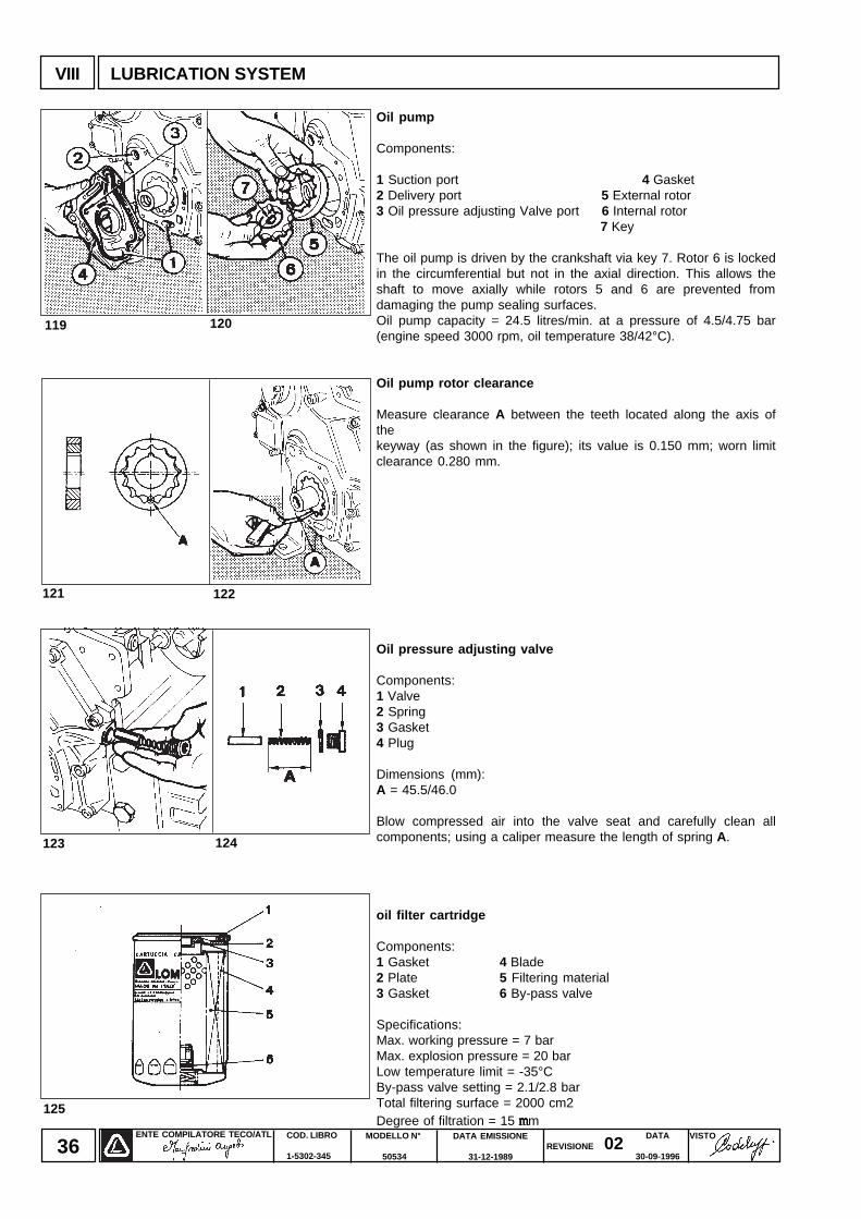
Oil pump
Components:
1 Suction port 4 Gasket2 Delivery port 5 External rotor3 Oil pressure adjusting Valve port 6 Internal rotor
7 Key
The oil pump is driven by the crankshaft via key 7. Rotor 6 is lockedin the circumferential but not in the axial direction. This allows theshaft to move axially while rotors 5 and 6 are prevented fromdamaging the pump sealing surfaces.Oil pump capacity = 24.5 litres/min. at a pressure of 4.5/4.75 bar(engine speed 3000 rpm, oil temperature 38/42°C).
Oil pump rotor clearance
Measure clearance A between the teeth located along the axis ofthekeyway (as shown in the figure); its value is 0.150 mm; worn limitclearance 0.280 mm.
Oil pressure adjusting valve
Components:1 Valve2 Spring3 Gasket4 Plug
Dimensions (mm):A = 45.5/46.0
Blow compressed air into the valve seat and carefully clean allcomponents; using a caliper measure the length of spring A.
oil filter cartridge
Components:1 Gasket 4 Blade2 Plate 5 Filtering material3 Gasket 6 By-pass valve
Specifications:Max. working pressure = 7 barMax. explosion pressure = 20 barLow temperature limit = -35°CBy-pass valve setting = 2.1/2.8 barTotal filtering surface = 2000 cm2Degree of filtration = 15 mmmmmm
121 122
123 124
125
ENTE COMPILATORE TECO/ATL VISTOREVISIONE 02
DATA EMISSIONE
31-12-1989
MODELLO N°
50534
COD. LIBRO
1-5302-345
DATA
30-09-199637
126
128127
129 130
131
LUBRICATION SYSTEM VIII
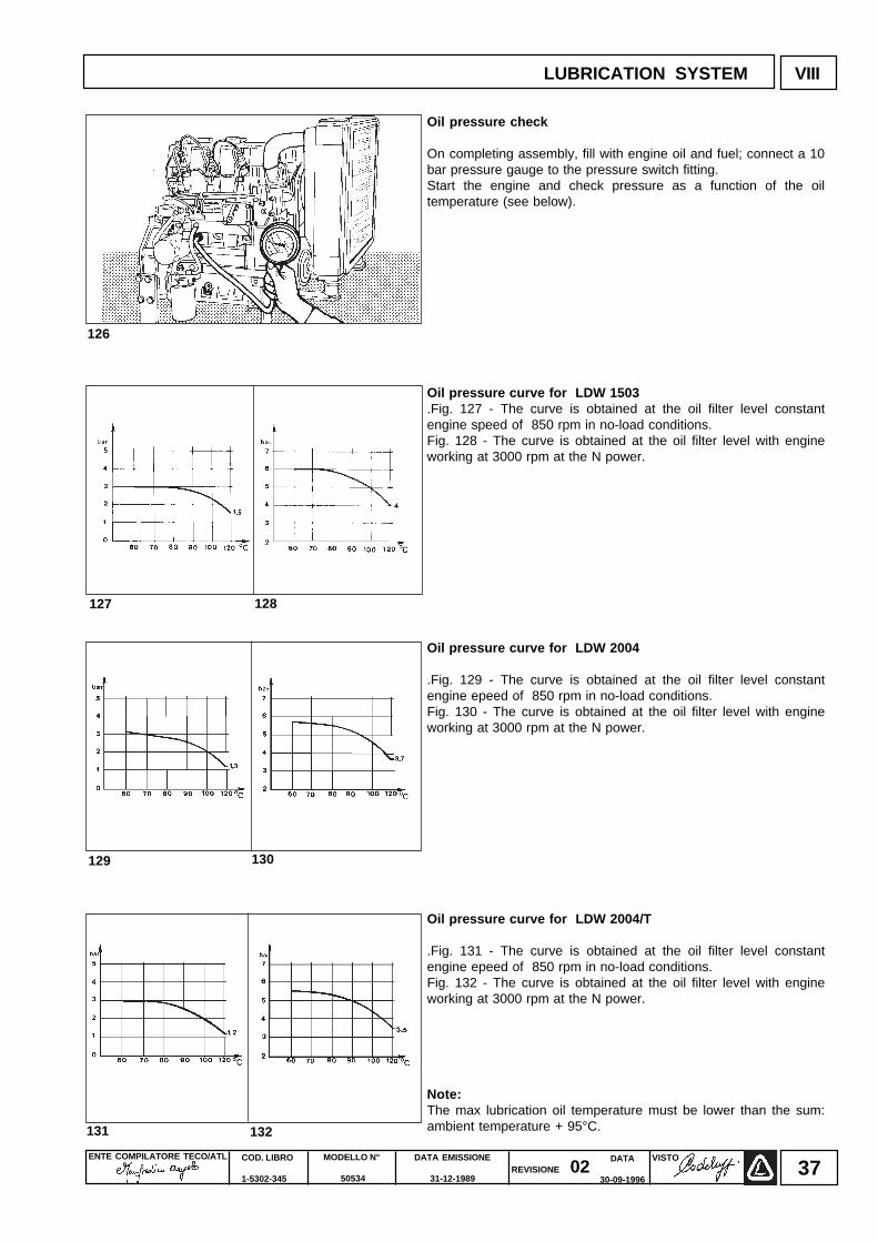
Oil pressure check
On completing assembly, fill with engine oil and fuel; connect a 10bar pressure gauge to the pressure switch fitting.Start the engine and check pressure as a function of the oiltemperature (see below).
Oil pressure curve for LDW 1503.Fig. 127 - The curve is obtained at the oil filter level constantengine speed of 850 rpm in no-load conditions.Fig. 128 - The curve is obtained at the oil filter level with engineworking at 3000 rpm at the N power.
Oil pressure curve for LDW 2004
.Fig. 129 - The curve is obtained at the oil filter level constantengine epeed of 850 rpm in no-load conditions.Fig. 130 - The curve is obtained at the oil filter level with engineworking at 3000 rpm at the N power.
Oil pressure curve for LDW 2004/T
.Fig. 131 - The curve is obtained at the oil filter level constantengine epeed of 850 rpm in no-load conditions.Fig. 132 - The curve is obtained at the oil filter level with engineworking at 3000 rpm at the N power.
Note:The max lubrication oil temperature must be lower than the sum:ambient temperature + 95°C.132
ENTE COMPILATORE TECO/ATL DATA EMISSIONE
31-12-1989
MODELLO N°
50534
COD. LIBRO
1-5302-345
VISTOREVISIONE 02
DATA
30-09-199638
IX COOLING SYSTEM
133
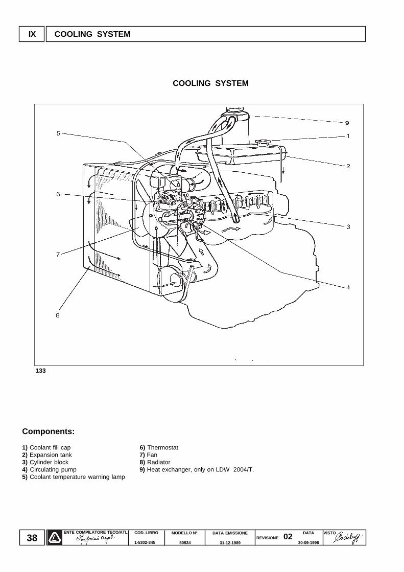
Components:
1) Coolant fill cap 6) Thermostat2) Expansion tank 7) Fan3) Cylinder block 8) Radiator4) Circulating pump 9) Heat exchanger, only on LDW 2004/T.5) Coolant temperature warning lamp
COOLING SYSTEM
ENTE COMPILATORE TECO/ATL VISTOREVISIONE 02
DATA EMISSIONE
31-12-1989
MODELLO N°
50534
COD. LIBRO
1-5302-345
DATA
30-09-199639
134
135
137136
139138
COOLING SYSTEM IX
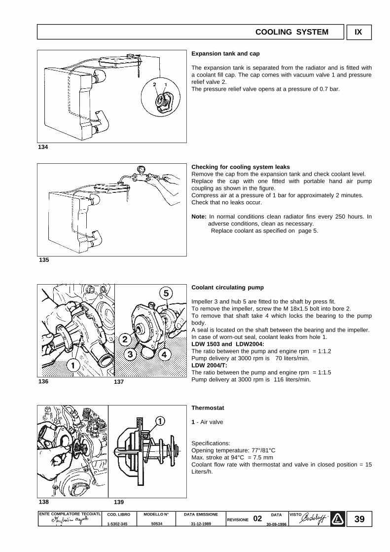
Expansion tank and cap
The expansion tank is separated from the radiator and is fitted witha coolant fill cap. The cap comes with vacuum valve 1 and pressurerelief valve 2.The pressure relief valve opens at a pressure of 0.7 bar.
Checking for cooling system leaksRemove the cap from the expansion tank and check coolant level.Replace the cap with one fitted with portable hand air pumpcoupling as shown in the figure.Compress air at a pressure of 1 bar for approximately 2 minutes.Check that no leaks occur.
Note: In normal conditions clean radiator fins every 250 hours. Inadverse conditions, clean as necessary.
Replace coolant as specified on page 5.
Coolant circulating pump
Impeller 3 and hub 5 are fitted to the shaft by press fit.To remove the impeller, screw the M 18x1.5 bolt into bore 2.To remove that shaft take 4 which locks the bearing to the pumpbody.A seal is located on the shaft between the bearing and the impeller.In case of worn-out seal, coolant leaks from hole 1.LDW 1503 and LDW2004:The ratio between the pump and engine rpm = 1:1.2Pump delivery at 3000 rpm is 70 liters/min.LDW 2004/T:The ratio between the pump and engine rpm = 1:1.5Pump delivery at 3000 rpm is 116 liters/min.
Thermostat
1 - Air valve
Specifications:Opening temperature: 77°/81°CMax. stroke at 94°C = 7.5 mmCoolant flow rate with thermostat and valve in closed position = 15Liters/h.
ENTE COMPILATORE TECO/ATL DATA EMISSIONE
31-12-1989
MODELLO N°
50534
COD. LIBRO
1-5302-345
VISTOREVISIONE 02
DATA
30-09-199640
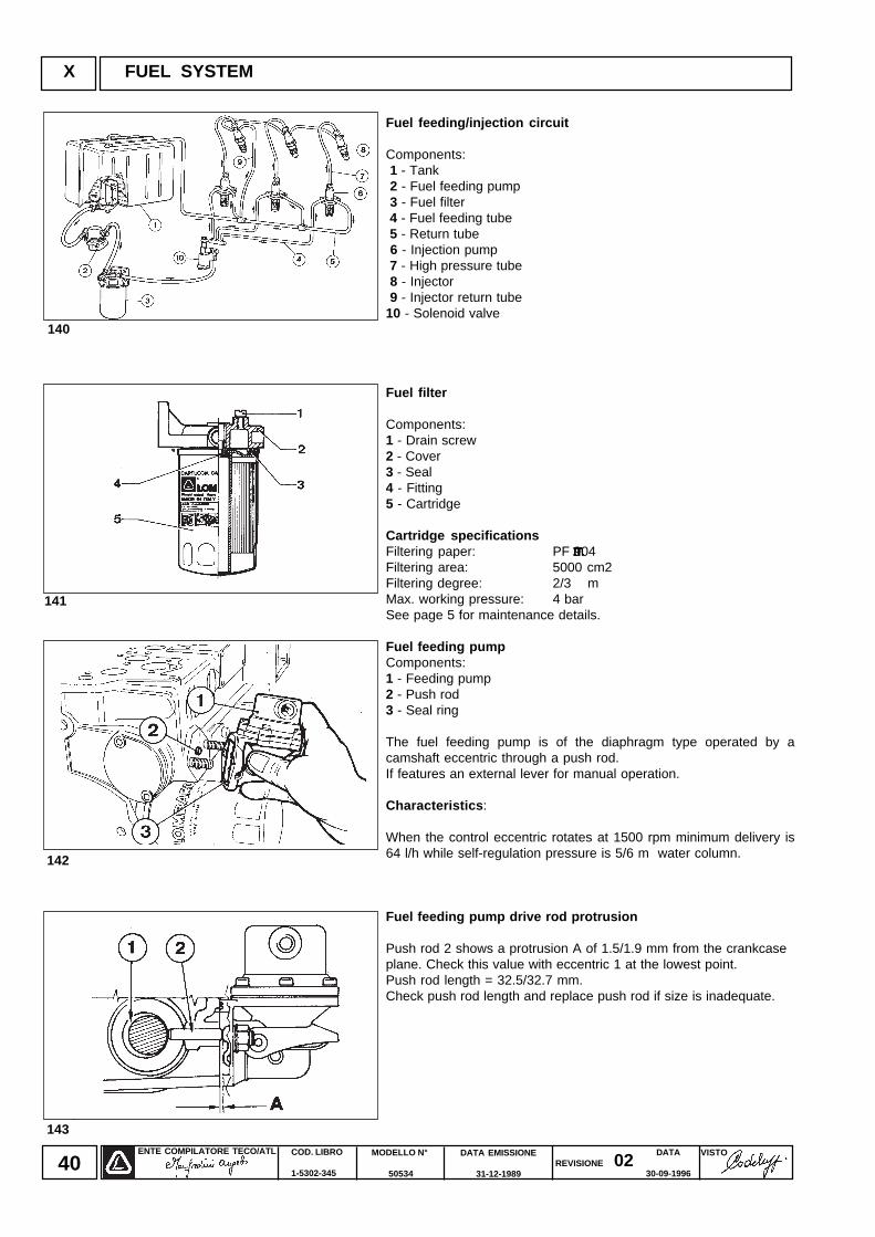
Fuel feeding/injection circuit
Components: 1 - Tank 2 - Fuel feeding pump 3 - Fuel filter 4 - Fuel feeding tube 5 - Return tube 6 - Injection pump 7 - High pressure tube 8 - Injector 9 - Injector return tube10 - Solenoid valve
Fuel filter
Components:1 - Drain screw2 - Cover3 - Seal4 - Fitting5 - Cartridge
Cartridge specificationsFiltering paper: PF 904Filtering area: 5000 cm2Filtering degree: 2/3 mMax. working pressure: 4 barSee page 5 for maintenance details.
Fuel feeding pumpComponents:1 - Feeding pump2 - Push rod3 - Seal ring
The fuel feeding pump is of the diaphragm type operated by acamshaft eccentric through a push rod.If features an external lever for manual operation.
Characteristics :
When the control eccentric rotates at 1500 rpm minimum delivery is64 l/h while self-regulation pressure is 5/6 m water column.
Fuel feeding pump drive rod protrusion
Push rod 2 shows a protrusion A of 1.5/1.9 mm from the crankcaseplane. Check this value with eccentric 1 at the lowest point.Push rod length = 32.5/32.7 mm.Check push rod length and replace push rod if size is inadequate.
X FUEL SYSTEM
140
141
143
142
mmmmm
ENTE COMPILATORE TECO/ATL VISTOREVISIONE 02
DATA EMISSIONE
31-12-1989
MODELLO N°
50534
COD. LIBRO
1-5302-345
DATA
30-09-199641
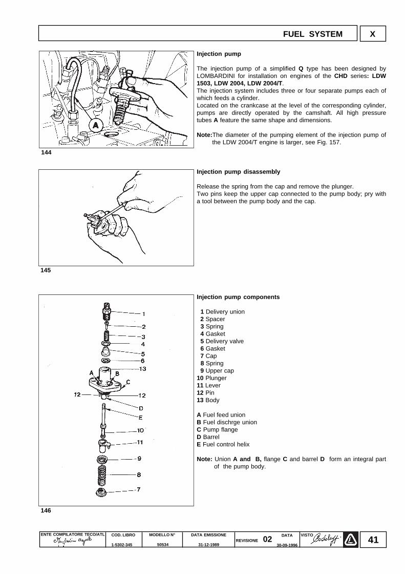
Injection pump
The injection pump of a simplified Q type has been designed byLOMBARDINI for installation on engines of the CHD series: LDW1503, LDW 2004, LDW 2004/T .The injection system includes three or four separate pumps each ofwhich feeds a cylinder.Located on the crankcase at the level of the corresponding cylinder,pumps are directly operated by the camshaft. All high pressuretubes A feature the same shape and dimensions.
Note: The diameter of the pumping element of the injection pump ofthe LDW 2004/T engine is larger, see Fig. 157.
Injection pump disassembly
Release the spring from the cap and remove the plunger.Two pins keep the upper cap connected to the pump body; pry witha tool between the pump body and the cap.
Injection pump components
1 Delivery union 2 Spacer 3 Spring 4 Gasket 5 Delivery valve 6 Gasket 7 Cap 8 Spring 9 Upper cap10 Plunger11 Lever12 Pin13 Body
A Fuel feed unionB Fuel dischrge unionC Pump flangeD BarrelE Fuel control helix
Note: Union A and B, flange C and barrel D form an integral partof the pump body.
145
144
146
FUEL SYSTEM X
ENTE COMPILATORE TECO/ATL DATA EMISSIONE
31-12-1989
MODELLO N°
50534
COD. LIBRO
1-5302-345
VISTOREVISIONE 02
DATA
30-09-199642
FUEL SYSTEMX
147
148
150149
152151
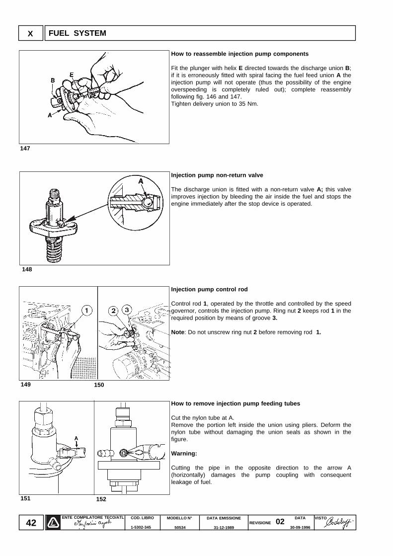
How to reassemble injection pump components
Fit the plunger with helix E directed towards the discharge union B;if it is erroneously fitted with spiral facing the fuel feed union A theinjection pump will not operate (thus the possibility of the engineoverspeeding is completely ruled out); complete reassemblyfollowing fig. 146 and 147.Tighten delivery union to 35 Nm.
Injection pump non-return valve
The discharge union is fitted with a non-return valve A; this valveimproves injection by bleeding the air inside the fuel and stops theengine immediately after the stop device is operated.
Injection pump control rod
Control rod 1, operated by the throttle and controlled by the speedgovernor, controls the injection pump. Ring nut 2 keeps rod 1 in therequired position by means of groove 3.
Note : Do not unscrew ring nut 2 before removing rod 1.
How to remove injection pump feeding tubes
Cut the nylon tube at A.Remove the portion left inside the union using pliers. Deform thenylon tube without damaging the union seals as shown in thefigure.
Warning:
Cutting the pipe in the opposite direction to the arrow A(horizontally) damages the pump coupling with consequentleakage of fuel.
ENTE COMPILATORE TECO/ATL VISTOREVISIONE 02
DATA EMISSIONE
31-12-1989
MODELLO N°
50534
COD. LIBRO
1-5302-345
DATA
30-09-199643
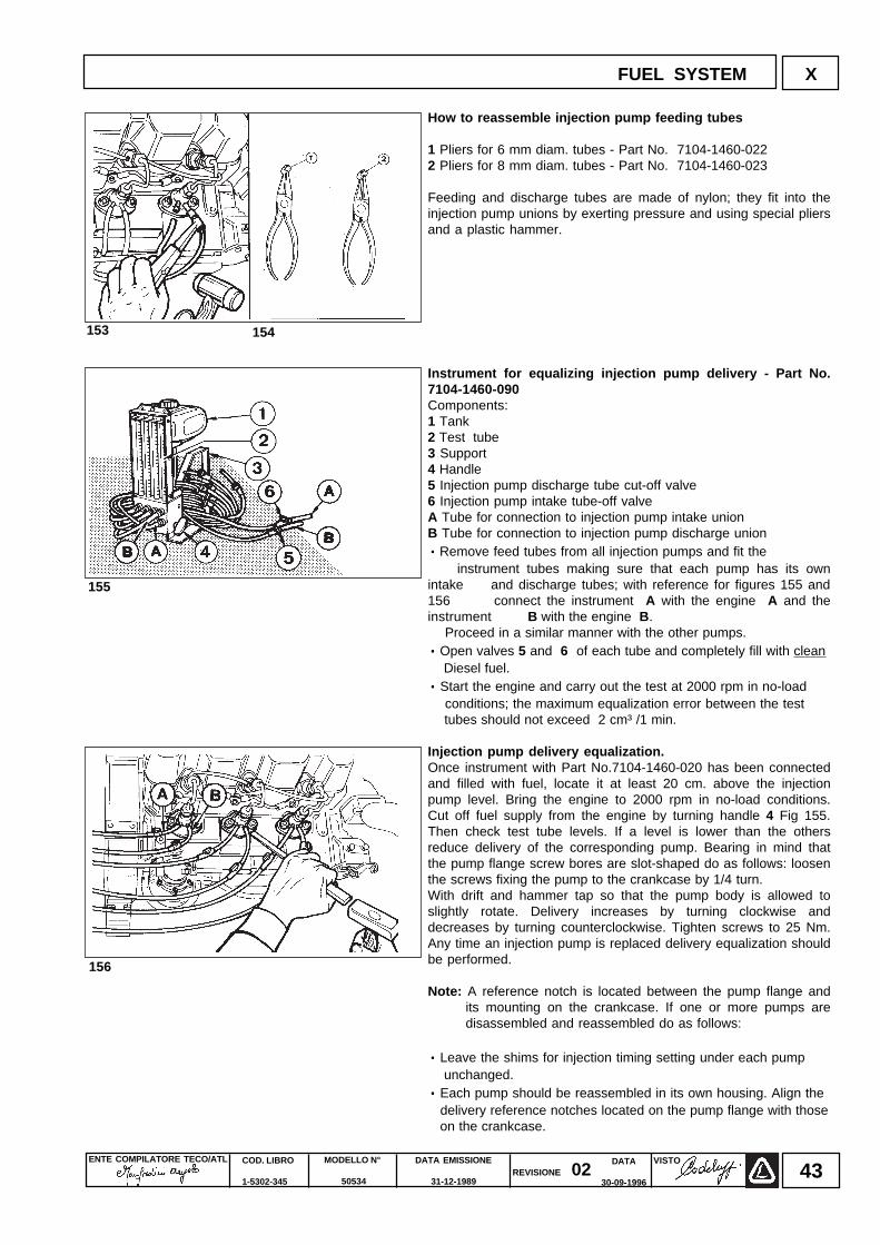
How to reassemble injection pump feeding tubes
1 Pliers for 6 mm diam. tubes - Part No. 7104-1460-0222 Pliers for 8 mm diam. tubes - Part No. 7104-1460-023
Feeding and discharge tubes are made of nylon; they fit into theinjection pump unions by exerting pressure and using special pliersand a plastic hammer.
Instrument for equalizing injection pump delivery - Part No.7104-1460-090Components:1 Tank2 Test tube3 Support4 Handle5 Injection pump discharge tube cut-off valve6 Injection pump intake tube-off valveA Tube for connection to injection pump intake unionB Tube for connection to injection pump discharge union····· Remove feed tubes from all injection pumps and fit the instrument tubes making sure that each pump has its ownintake and discharge tubes; with reference for figures 155 and156 connect the instrument A with the engine A and theinstrument B with the engine B. Proceed in a similar manner with the other pumps.· · · · · Open valves 5 and 6 of each tube and completely fill with clean Diesel fuel.· · · · · Start the engine and carry out the test at 2000 rpm in no-load conditions; the maximum equalization error between the test tubes should not exceed 2 cm³ /1 min.
Injection pump delivery equalization.Once instrument with Part No.7104-1460-020 has been connectedand filled with fuel, locate it at least 20 cm. above the injectionpump level. Bring the engine to 2000 rpm in no-load conditions.Cut off fuel supply from the engine by turning handle 4 Fig 155.Then check test tube levels. If a level is lower than the othersreduce delivery of the corresponding pump. Bearing in mind thatthe pump flange screw bores are slot-shaped do as follows: loosenthe screws fixing the pump to the crankcase by 1/4 turn.With drift and hammer tap so that the pump body is allowed toslightly rotate. Delivery increases by turning clockwise anddecreases by turning counterclockwise. Tighten screws to 25 Nm.Any time an injection pump is replaced delivery equalization shouldbe performed.
Note: A reference notch is located between the pump flange andits mounting on the crankcase. If one or more pumps aredisassembled and reassembled do as follows:
· · · · · Leave the shims for injection timing setting under each pump unchanged.· · · · · Each pump should be reassembled in its own housing. Align the delivery reference notches located on the pump flange with those on the crankcase.
154153
155
156
FUEL SYSTEM X
ENTE COMPILATORE TECO/ATL DATA EMISSIONE
31-12-1989
MODELLO N°
50534
COD. LIBRO
1-5302-345
VISTOREVISIONE 02
DATA
30-09-199644
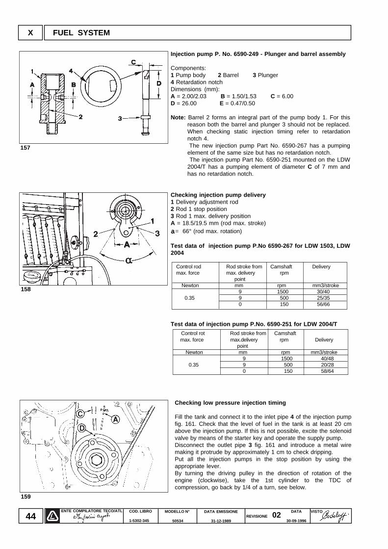
Injection pump P. No. 6590-249 - Plunger and barrel assembly
Components:1 Pump body 2 Barrel 3 Plunger4 Retardation notchDimensions (mm):A = 2.00/2.03 B = 1.50/1.53 C = 6.00D = 26.00 E = 0.47/0.50
Note: Barrel 2 forms an integral part of the pump body 1. For thisreason both the barrel and plunger 3 should not be replaced.When checking static injection timing refer to retardationnotch 4.
The new injection pump Part No. 6590-267 has a pumpingelement of the same size but has no retardation notch.
The injection pump Part No. 6590-251 mounted on the LDW2004/T has a pumping element of diameter C of 7 mm andhas no retardation notch.
Checking injection pump delivery1 Delivery adjustment rod2 Rod 1 stop position3 Rod 1 max. delivery positionA = 18.5/19.5 mm (rod max. stroke)aaaaa= 66° (rod max. rotation)
Test data of injection pump P.No 6590-267 for LDW 1503, LDW2004
Control rod Rod stroke from Camshaft Delivery max. force max. delivery rpm
point Newton mm rpm mm3/stroke
9 1500 30/40 0.35 9 500 25/35
0 150 56/66
Test data of injection pump P.No. 6590-251 for LDW 2004/T
X FUEL SYSTEM
157
158
159
Control rot Rod stroke from Camshaft max. force max.delivery rpm Delivery
point Newton mm rpm mm3/stroke
9 1500 40/48 0.35 9 500 20/28
0 150 58/64
Checking low pressure injection timing
Fill the tank and connect it to the inlet pipe 4 of the injection pumpfig. 161. Check that the level of fuel in the tank is at least 20 cmabove the injection pump. If this is not possible, excite the solenoidvalve by means of the starter key and operate the supply pump.Disconnect the outlet pipe 3 fig. 161 and introduce a metal wiremaking it protrude by approximately 1 cm to check dripping.Put all the injection pumps in the stop position by using theappropriate lever.By turning the driving pulley in the direction of rotation of theengine (clockwise), take the 1st cylinder to the TDC ofcompression, go back by 1/4 of a turn, see below.
ENTE COMPILATORE TECO/ATL VISTOREVISIONE 02
DATA EMISSIONE
31-12-1989
MODELLO N°
50534
COD. LIBRO
1-5302-345
DATA
30-09-199645
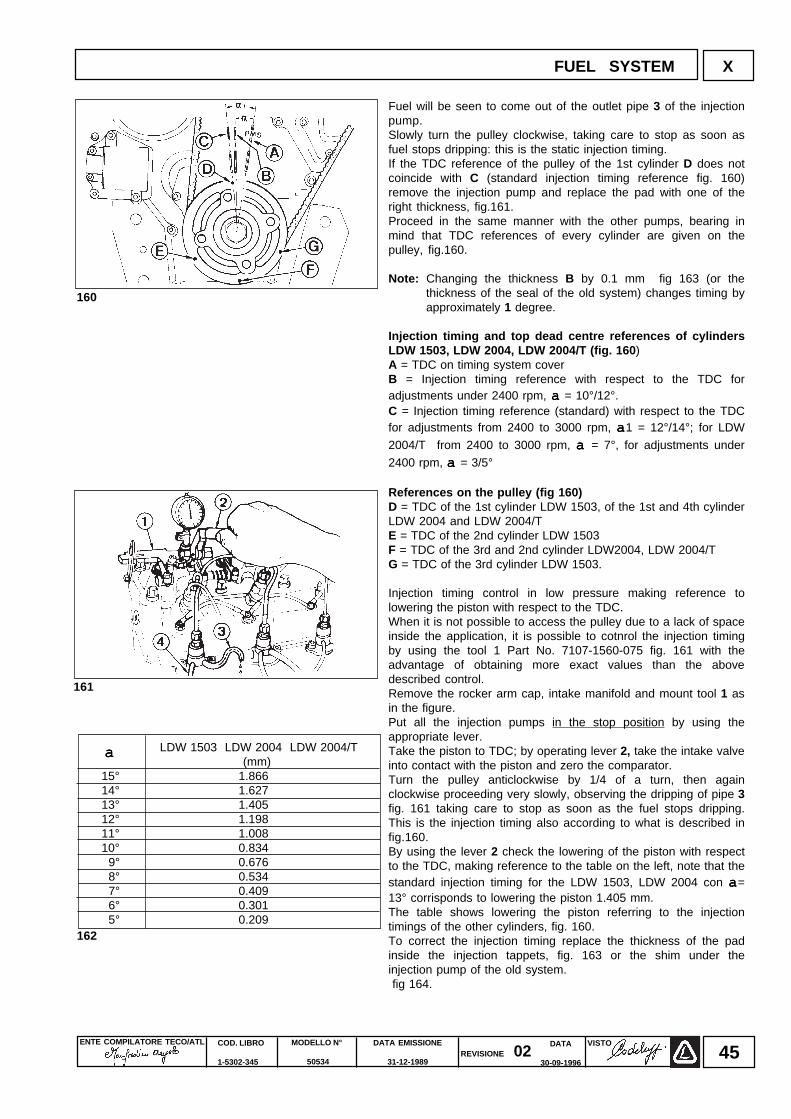
Fuel will be seen to come out of the outlet pipe 3 of the injectionpump.Slowly turn the pulley clockwise, taking care to stop as soon asfuel stops dripping: this is the static injection timing.If the TDC reference of the pulley of the 1st cylinder D does notcoincide with C (standard injection timing reference fig. 160)remove the injection pump and replace the pad with one of theright thickness, fig.161.Proceed in the same manner with the other pumps, bearing inmind that TDC references of every cylinder are given on thepulley, fig.160.
Note: Changing the thickness B by 0.1 mm fig 163 (or thethickness of the seal of the old system) changes timing byapproximately 1 degree.
Injection timing and top dead centre references of cylindersLDW 1503, LDW 2004, LDW 2004/T (fig. 160 )A = TDC on timing system coverB = Injection timing reference with respect to the TDC foradjustments under 2400 rpm, a a a a a = 10°/12°.C = Injection timing reference (standard) with respect to the TDCfor adjustments from 2400 to 3000 rpm, aaaaa1 = 12°/14°; for LDW
2004/T from 2400 to 3000 rpm, a a a a a = 7°, for adjustments under
2400 rpm, a a a a a = 3/5°
References on the pulley (fig 160)D = TDC of the 1st cylinder LDW 1503, of the 1st and 4th cylinderLDW 2004 and LDW 2004/TE = TDC of the 2nd cylinder LDW 1503F = TDC of the 3rd and 2nd cylinder LDW2004, LDW 2004/TG = TDC of the 3rd cylinder LDW 1503.
Injection timing control in low pressure making reference tolowering the piston with respect to the TDC.When it is not possible to access the pulley due to a lack of spaceinside the application, it is possible to cotnrol the injection timingby using the tool 1 Part No. 7107-1560-075 fig. 161 with theadvantage of obtaining more exact values than the abovedescribed control.Remove the rocker arm cap, intake manifold and mount tool 1 asin the figure.Put all the injection pumps in the stop position by using theappropriate lever.Take the piston to TDC; by operating lever 2, take the intake valveinto contact with the piston and zero the comparator.Turn the pulley anticlockwise by 1/4 of a turn, then againclockwise proceeding very slowly, observing the dripping of pipe 3fig. 161 taking care to stop as soon as the fuel stops dripping.This is the injection timing also according to what is described infig.160.By using the lever 2 check the lowering of the piston with respectto the TDC, making reference to the table on the left, note that thestandard injection timing for the LDW 1503, LDW 2004 con aaaaa=13° corrisponds to lowering the piston 1.405 mm.The table shows lowering the piston referring to the injectiontimings of the other cylinders, fig. 160.To correct the injection timing replace the thickness of the padinside the injection tappets, fig. 163 or the shim under theinjection pump of the old system. fig 164.
LDW 1503 LDW 2004 LDW 2004/T (mm)
15° 1.866 14° 1.627 13° 1.405 12° 1.198 11° 1.008 10° 0.834 9° 0.676 8° 0.534 7° 0.409 6° 0.301 5° 0.209162
aaaaa
161
160
FUEL SYSTEM X
ENTE COMPILATORE TECO/ATL DATA EMISSIONE
31-12-1989
MODELLO N°
50534
COD. LIBRO
1-5302-345
VISTOREVISIONE 02
DATA
30-09-199646
FUEL SYSTEMX
163 164
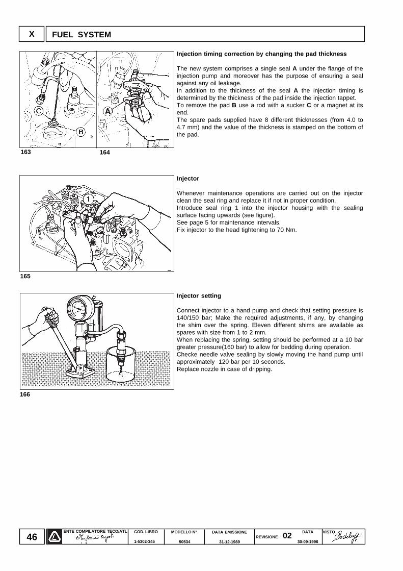
Injection timing correction by changing the pad thickness
The new system comprises a single seal A under the flange of theinjection pump and moreover has the purpose of ensuring a sealagainst any oil leakage.In addition to the thickness of the seal A the injection timing isdetermined by the thickness of the pad inside the injection tappet.To remove the pad B use a rod with a sucker C or a magnet at itsend.The spare pads supplied have 8 different thicknesses (from 4.0 to4.7 mm) and the value of the thickness is stamped on the bottom ofthe pad.
Injector
Whenever maintenance operations are carried out on the injectorclean the seal ring and replace it if not in proper condition.Introduce seal ring 1 into the injector housing with the sealingsurface facing upwards (see figure).See page 5 for maintenance intervals.Fix injector to the head tightening to 70 Nm.
Injector setting
Connect injector to a hand pump and check that setting pressure is140/150 bar; Make the required adjustments, if any, by changingthe shim over the spring. Eleven different shims are available asspares with size from 1 to 2 mm.When replacing the spring, setting should be performed at a 10 bargreater pressure(160 bar) to allow for bedding during operation.Checke needle valve sealing by slowly moving the hand pump untilapproximately 120 bar per 10 seconds.Replace nozzle in case of dripping.
165
166
ENTE COMPILATORE TECO/ATL VISTOREVISIONE 02
DATA EMISSIONE
31-12-1989
MODELLO N°
50534
COD. LIBRO
1-5302-345
DATA
30-09-199647
Alternator type Marelli AA 125 R 14V 45A
Characteristics:Rated voltage = 14VRated current = 45AMax. speed = 14000 giri/1'Peak speed (max 15 min) = 15000 rpmBearing on control side = 6203.2zBearing on manifold side = 6201-2z/C3Voltage regulator = RTT 119 ACRH direction of rotation.
Note : Lube the two bearings with high temperature grease. Tighten the nut 1 to 60 Nm. The alternator has a W terminal for a speed indicator.
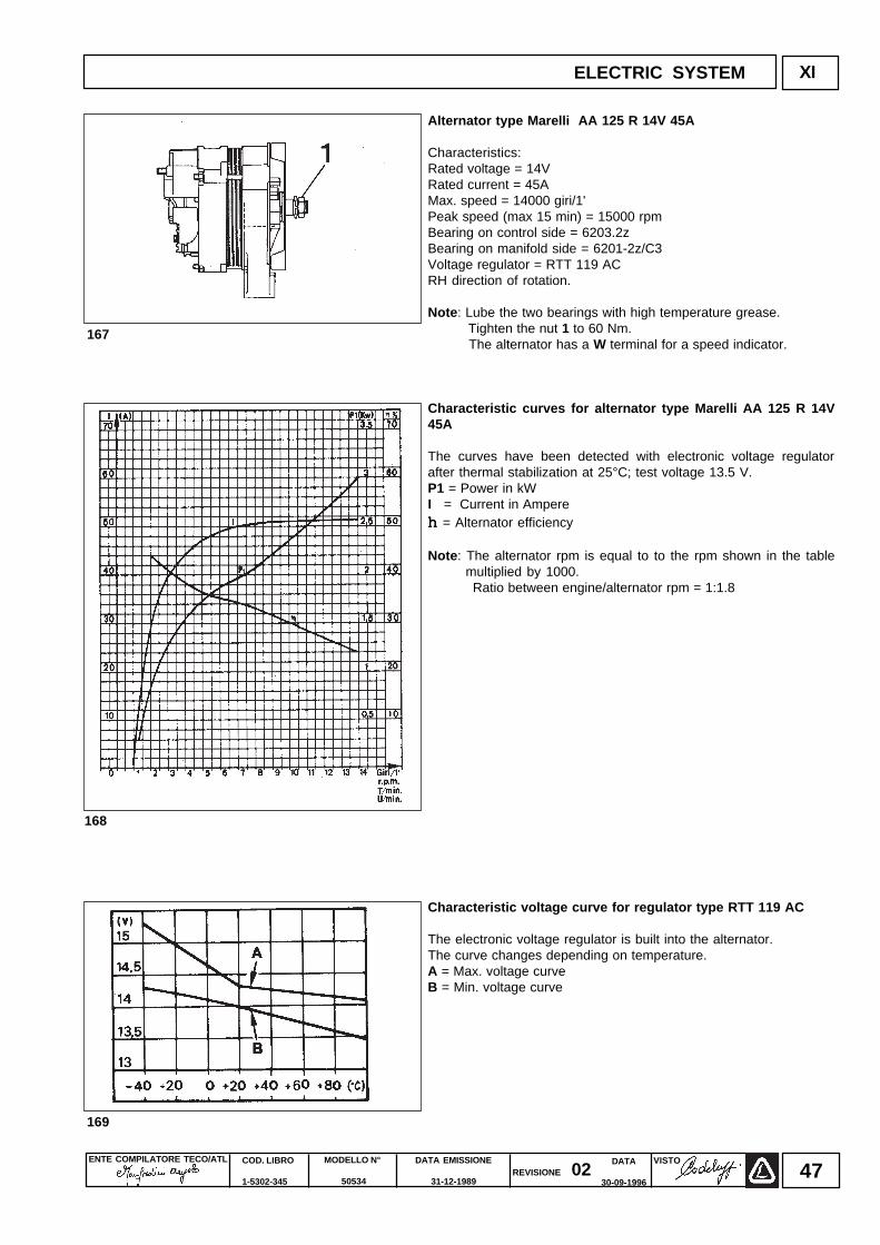
Characteristic curves for alternator type Marelli AA 125 R 14V45A
The curves have been detected with electronic voltage regulatorafter thermal stabilization at 25°C; test voltage 13.5 V.P1 = Power in kWI = Current in Ampereh h h h h = Alternator efficiency
Note : The alternator rpm is equal to to the rpm shown in the tablemultiplied by 1000.
Ratio between engine/alternator rpm = 1:1.8
Characteristic voltage curve for regulator type RTT 119 AC
The electronic voltage regulator is built into the alternator.The curve changes depending on temperature.A = Max. voltage curveB = Min. voltage curve
XIELECTRIC SYSTEM
167
168
169
ENTE COMPILATORE TECO/ATL DATA EMISSIONE
31-12-1989
MODELLO N°
50534
COD. LIBRO
1-5302-345
VISTOREVISIONE 02
DATA
30-09-199648
XI ELECTRIC SYSTEM
LDW 1503
LDW 2004
LDW 2004/T
Starter Rating
(Kw)
Amp-Hours@
20 hoursRating
Maxim.BatteryAmps
@-18° C
Amp-Hours@
20 hoursRating
2.2 88 330 110 450
3 110 450 143 570
2.2 88 330 110 450
3 110 540 143 570
2.2 88 330 110 450
3 110 540 143 570
Engine Model
Extreme Ambient
Conditions
Normal Ambient
Conditions
170
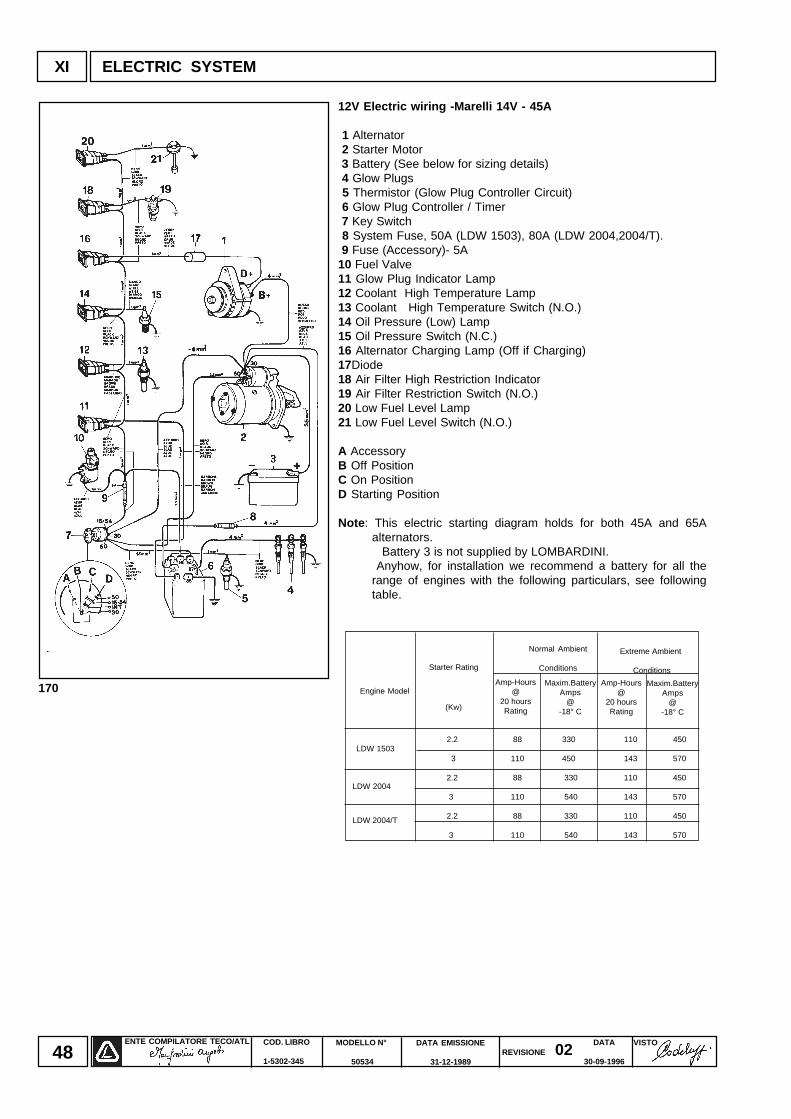
12V Electric wiring -Marelli 14V - 45A
1 Alternator 2 Starter Motor 3 Battery (See below for sizing details) 4 Glow Plugs 5 Thermistor (Glow Plug Controller Circuit) 6 Glow Plug Controller / Timer 7 Key Switch 8 System Fuse, 50A (LDW 1503), 80A (LDW 2004,2004/T). 9 Fuse (Accessory)- 5A10 Fuel Valve11 Glow Plug Indicator Lamp12 Coolant High Temperature Lamp13 Coolant High Temperature Switch (N.O.)14 Oil Pressure (Low) Lamp15 Oil Pressure Switch (N.C.)16 Alternator Charging Lamp (Off if Charging)17Diode18 Air Filter High Restriction Indicator19 Air Filter Restriction Switch (N.O.)20 Low Fuel Level Lamp21 Low Fuel Level Switch (N.O.)
A AccessoryB Off PositionC On PositionD Starting Position
Note : This electric starting diagram holds for both 45A and 65Aalternators.
Battery 3 is not supplied by LOMBARDINI. Anyhow, for installation we recommend a battery for all the
range of engines with the following particulars, see followingtable.
Maxim.BatteryAmps
@-18° C
ENTE COMPILATORE TECO/ATL VISTOREVISIONE 02
DATA EMISSIONE
31-12-1989
MODELLO N°
50534
COD. LIBRO
1-5302-345
DATA
30-09-199649
XI
171
172
173
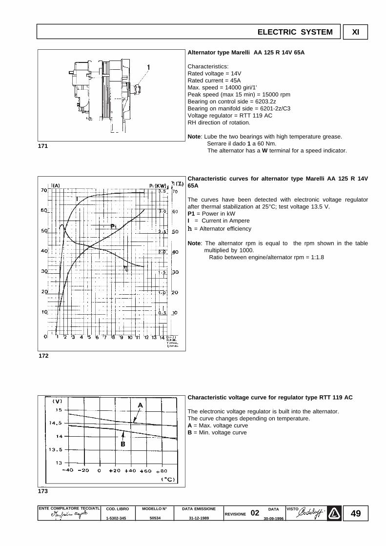
Alternator type Marelli AA 125 R 14V 65A
Characteristics:Rated voltage = 14VRated current = 45AMax. speed = 14000 giri/1'Peak speed (max 15 min) = 15000 rpmBearing on control side = 6203.2zBearing on manifold side = 6201-2z/C3Voltage regulator = RTT 119 ACRH direction of rotation.
Note : Lube the two bearings with high temperature grease. Serrare il dado 1 a 60 Nm. The alternator has a W terminal for a speed indicator.
Characteristic curves for alternator type Marelli AA 125 R 14V65A
The curves have been detected with electronic voltage regulatorafter thermal stabilization at 25°C; test voltage 13.5 V.P1 = Power in kWI = Current in Ampereh h h h h = Alternator efficiency
Note : The alternator rpm is equal to the rpm shown in the tablemultiplied by 1000.
Ratio between engine/alternator rpm = 1:1.8
Characteristic voltage curve for regulator type RTT 119 AC
The electronic voltage regulator is built into the alternator.The curve changes depending on temperature.A = Max. voltage curveB = Min. voltage curve
ELECTRIC SYSTEM
ENTE COMPILATORE TECO/ATL DATA EMISSIONE
31-12-1989
MODELLO N°
50534
COD. LIBRO
1-5302-345
VISTOREVISIONE 02
DATA
30-09-199650
ELECTRIC SYSTEMXI
174
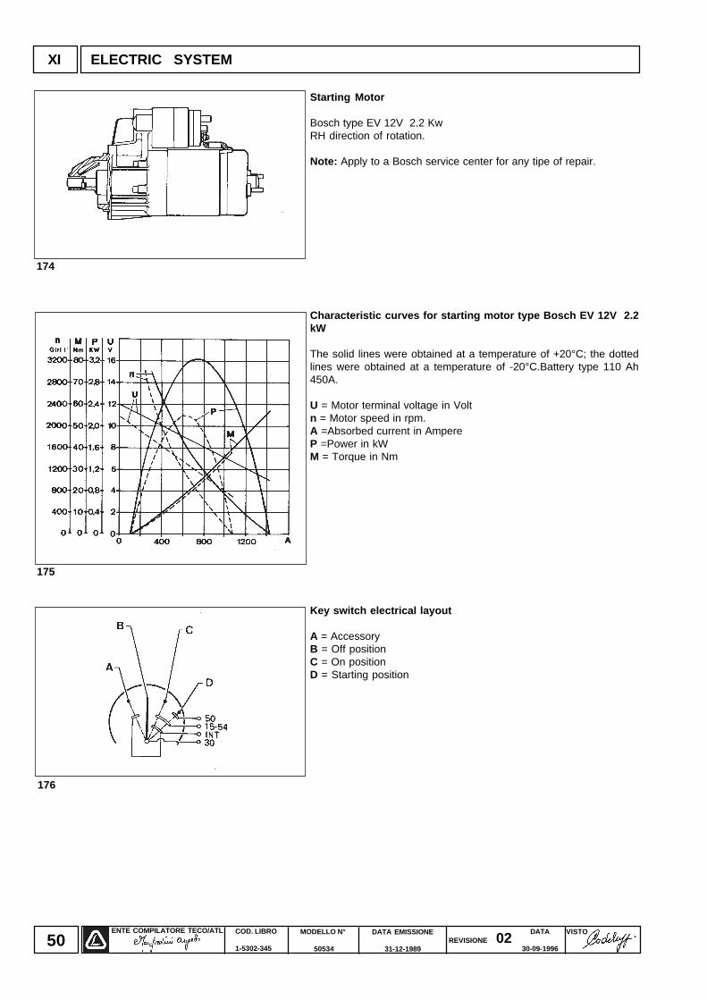
Starting Motor
Bosch type EV 12V 2.2 KwRH direction of rotation.
Note: Apply to a Bosch service center for any tipe of repair.
Characteristic curves for starting motor type Bosch EV 12V 2.2kW
The solid lines were obtained at a temperature of +20°C; the dottedlines were obtained at a temperature of -20°C.Battery type 110 Ah450A.
U = Motor terminal voltage in Voltn = Motor speed in rpm.A =Absorbed current in AmpereP =Power in kWM = Torque in Nm
Key switch electrical layout
A = AccessoryB = Off positionC = On positionD = Starting position
175
176
ENTE COMPILATORE TECO/ATL VISTOREVISIONE 02
DATA EMISSIONE
31-12-1989
MODELLO N°
50534
COD. LIBRO
1-5302-345
DATA
30-09-199651
ELECTRIC SYSTEM XI
177 178
180 181
183182
179
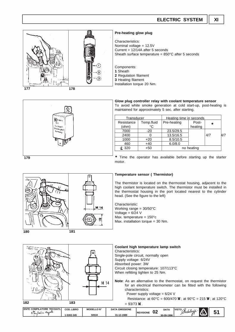
Pre-heating glow plug
Characteristics:Nominal voltage = 12.5VCurrent = 12/14A after 5 secondsSheath surface temperature = 850°C after 5 seconds
Components:1 Sheath2 Regulation filament3 Heating filamentInstallation torque 20 Nm.
Glow plug controller relay with coolant temperature sensorTo avoid white smoke generation at cold start-up, post-heating ismaintained for approximately 5 sec. after starting.
Transducer Heating time in seconds Resistance Temp.fluid Pre-heating Post- (ohm) °C heating 7000 -20 23.5/29.5 2400 0 13.5/16.5 4/7 4/7 1000 +20 8.5/10.5 460 +40 6.0/8.0 320 +50 no heating
* * * * * Time the operator has available before starting up the startermotor.
Temperature sensor ( Thermistor)
The thermistor is located on the thermostat housing, adjacent to thehigh coolant temperature switch. The thermistor must be installed inthe thermostat housing in the port located nearest to the cylinderhead. (See the figure to the left)
Characteristic:Working range = 30/50°CVoltage = 6/24 VMax. temperature = 150°cMax. installation torque = 30 Nm.
Coolant high temperature lamp switchCharacteristics:Single-pole circuit, normally openSupply voltage: 6/24VAbsorbed power: 3WCircuit closing temperature: 107/113°CWhen refitting tighten to 25 Nm.
Note : As an alternative to the thermostat, on request the thermistorfor an electrical thermometer can be fitted with the followingcharacteristics:
Power supply voltage = 6/24 V Resistance: at 60°C = 600/470 WWWWW; at 90°C = 215 WWWWW; at 120°C
= 93/73 WWWWW.
£££££
*****
ENTE COMPILATORE TECO/ATL DATA EMISSIONE
31-12-1989
MODELLO N°
50534
COD. LIBRO
1-5302-345
VISTOREVISIONE 02
DATA
30-09-199652
XII SETTINGS
184
Settings
Idling speed setting in no-load conditions (standard)
After filling with oil, fuel and coolant, start the engine and warm upfor 10 minutes.Adjust idling speed at 850.950 rpm by turning screw 1 then tightenlock nut.
Note: Speed decreases when loosening scew 1 and increaseswhen tightening it.
Full speed setting in no-load conditions (standard )
After setting idle speed turn screw 2 and set full speed in no-loadconditions at 3200 rpm; then tighten lock nut.When the engine reaches the pre-set power, full speed stabilizes at3000 rpm.
Nota : Speed increases when loosening scew 2 and decreaseswhen tightening it.
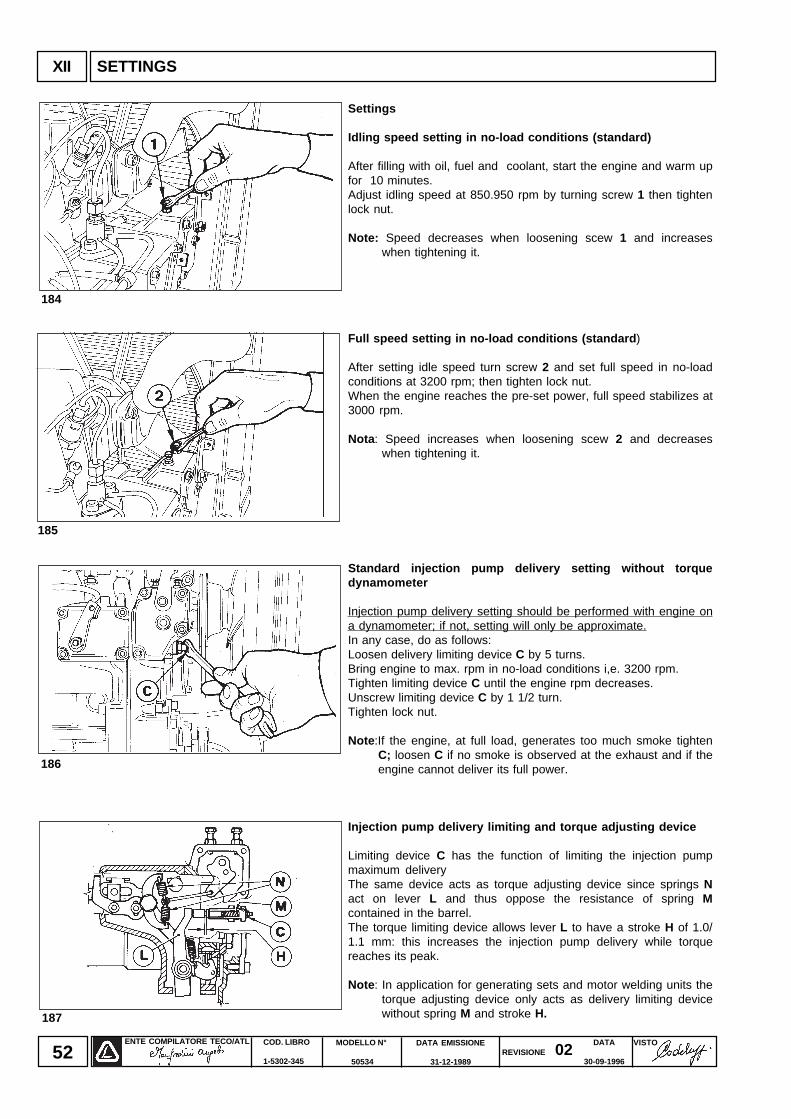
Standard injection pump delivery setting without torquedynamometer
Injection pump delivery setting should be performed with engine ona dynamometer; if not, setting will only be approximate.In any case, do as follows:Loosen delivery limiting device C by 5 turns.Bring engine to max. rpm in no-load conditions i,e. 3200 rpm.Tighten limiting device C until the engine rpm decreases.Unscrew limiting device C by 1 1/2 turn.Tighten lock nut.
Note :If the engine, at full load, generates too much smoke tightenC; loosen C if no smoke is observed at the exhaust and if theengine cannot deliver its full power.
Injection pump delivery limiting and torque adjusting device
Limiting device C has the function of limiting the injection pumpmaximum deliveryThe same device acts as torque adjusting device since springs Nact on lever L and thus oppose the resistance of spring Mcontained in the barrel.The torque limiting device allows lever L to have a stroke H of 1.0/1.1 mm: this increases the injection pump delivery while torquereaches its peak.
Note : In application for generating sets and motor welding units thetorque adjusting device only acts as delivery limiting devicewithout spring M and stroke H.187
186
185
ENTE COMPILATORE TECO/ATL VISTOREVISIONE 02
DATA EMISSIONE
31-12-1989
MODELLO N°
50534
COD. LIBRO
1-5302-345
DATA
30-09-199653
188
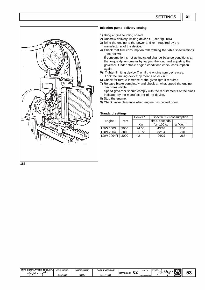
Injection pump delivery setting
1) Bring engine to idling speed2) Unscrew delivery limiting device C ( see fig. 186)3) Bring the engine to the power and rpm required by the manufacturer of the device.4) Check that fuel consumption falls withing the table specifications (see below). If consumption is not as indicated change balance conditions at the torque dynamometer by varying the load and adjusting the governor. Under stable engine conditions check consumption again.5) Tighten limiting device C until the engine rpm decreases. Lock the limiting device by means of lock nut.6) Check for torque increase at the given rpm if required.7) Release brake completely and check at what speed the engine becomes stable Speed governor should comply with the requirements of the class indicated by the manufacturer of the device.8) Stop the engine.9) Check valve clearance when engine has cooled down.
Standard settings Power * Specific fuel consumption
Engine rpm time, seconds Kw for 100 cc gr/Kw.h
LDW 1503 3000 24.56 43/46 280 LDW 2004 3000 32.72 32/34 270 LDW 2004/T 3000 42 26/27 265
SETTINGS XII
ENTE COMPILATORE TECO/ATL DATA EMISSIONE
31-12-1989
MODELLO N°
50534
COD. LIBRO
1-5302-345
VISTOREVISIONE 02
DATA
30-09-199654
XIII SETTINGS
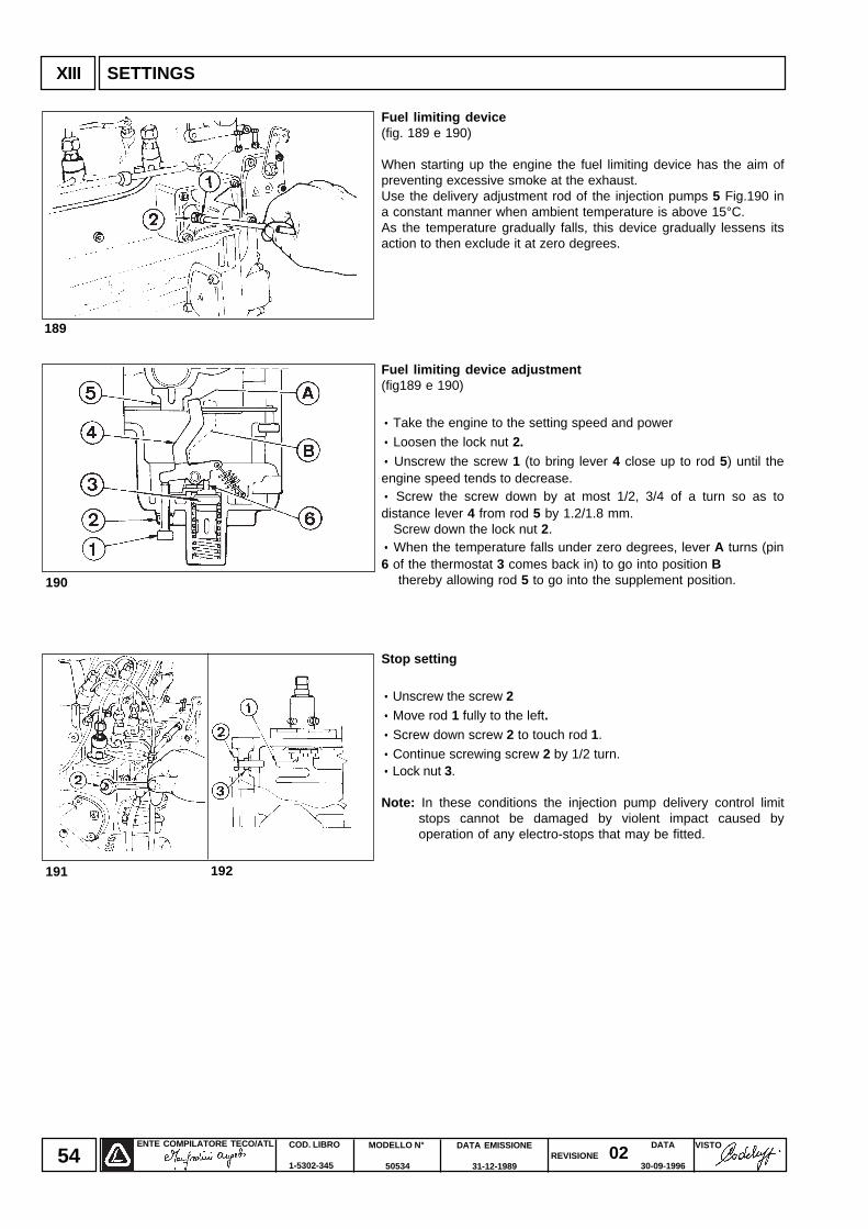
Fuel limiting device(fig. 189 e 190)
When starting up the engine the fuel limiting device has the aim ofpreventing excessive smoke at the exhaust.Use the delivery adjustment rod of the injection pumps 5 Fig.190 ina constant manner when ambient temperature is above 15°C.As the temperature gradually falls, this device gradually lessens itsaction to then exclude it at zero degrees.
Fuel limiting device adjustment(fig189 e 190)
· · · · · Take the engine to the setting speed and power
· · · · · Loosen the lock nut 2.· · · · · Unscrew the screw 1 (to bring lever 4 close up to rod 5) until theengine speed tends to decrease.· · · · · Screw the screw down by at most 1/2, 3/4 of a turn so as todistance lever 4 from rod 5 by 1.2/1.8 mm. Screw down the lock nut 2.· · · · · When the temperature falls under zero degrees, lever A turns (pin6 of the thermostat 3 comes back in) to go into position B thereby allowing rod 5 to go into the supplement position.
Stop setting
· · · · · Unscrew the screw 2· · · · · Move rod 1 fully to the left.· · · · · Screw down screw 2 to touch rod 1.
· · · · · Continue screwing screw 2 by 1/2 turn.· · · · · Lock nut 3.
Note: In these conditions the injection pump delivery control limitstops cannot be damaged by violent impact caused byoperation of any electro-stops that may be fitted.
190
189
192191
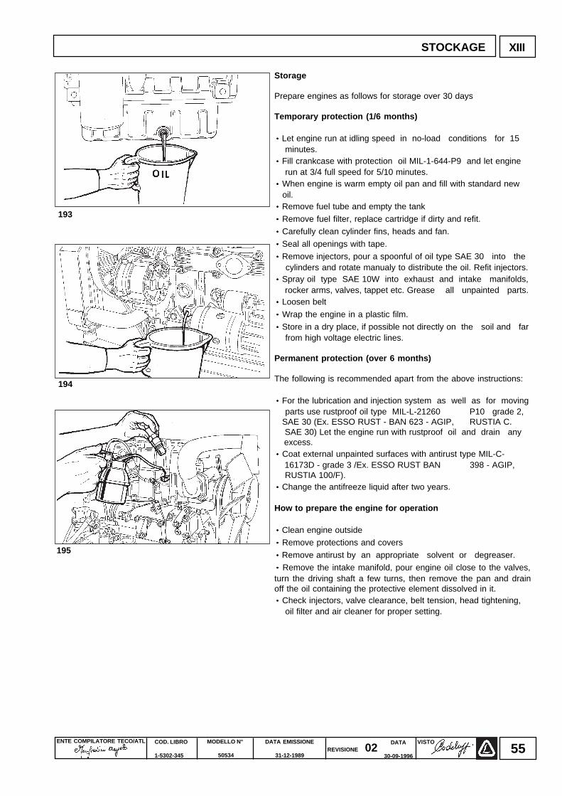
ENTE COMPILATORE TECO/ATL VISTOREVISIONE 02
DATA EMISSIONE
31-12-1989
MODELLO N°
50534
COD. LIBRO
1-5302-345
DATA
30-09-199655
Storage
Prepare engines as follows for storage over 30 days
Temporary protection (1/6 months)
· · · · · Let engine run at idling speed in no-load conditions for 15 minutes.· · · · · Fill crankcase with protection oil MIL-1-644-P9 and let engine run at 3/4 full speed for 5/10 minutes.· · · · · When engine is warm empty oil pan and fill with standard new oil.· · · · · Remove fuel tube and empty the tank
· · · · · Remove fuel filter, replace cartridge if dirty and refit.
· · · · · Carefully clean cylinder fins, heads and fan.
· · · · · Seal all openings with tape.
· · · · · Remove injectors, pour a spoonful of oil type SAE 30 into the cylinders and rotate manualy to distribute the oil. Refit injectors.· · · · · Spray oil type SAE 10W into exhaust and intake manifolds, rocker arms, valves, tappet etc. Grease all unpainted parts.· · · · · Loosen belt
· · · · · Wrap the engine in a plastic film.
· · · · · Store in a dry place, if possible not directly on the soil and far from high voltage electric lines.
Permanent protection (over 6 months)
The following is recommended apart from the above instructions:
· · · · · For the lubrication and injection system as well as for moving parts use rustproof oil type MIL-L-21260 P10 grade 2, SAE 30 (Ex. ESSO RUST - BAN 623 - AGIP, RUSTIA C. SAE 30) Let the engine run with rustproof oil and drain any excess.· · · · · Coat external unpainted surfaces with antirust type MIL-C- 16173D - grade 3 /Ex. ESSO RUST BAN 398 - AGIP, RUSTIA 100/F).· · · · · Change the antifreeze liquid after two years.
How to prepare the engine for operation
· · · · · Clean engine outside
· · · · · Remove protections and covers
· · · · · Remove antirust by an appropriate solvent or degreaser.
· · · · · Remove the intake manifold, pour engine oil close to the valves,turn the driving shaft a few turns, then remove the pan and drainoff the oil containing the protective element dissolved in it.· · · · · Check injectors, valve clearance, belt tension, head tightening, oil filter and air cleaner for proper setting.
194
193
195
XIIISTOCKAGE
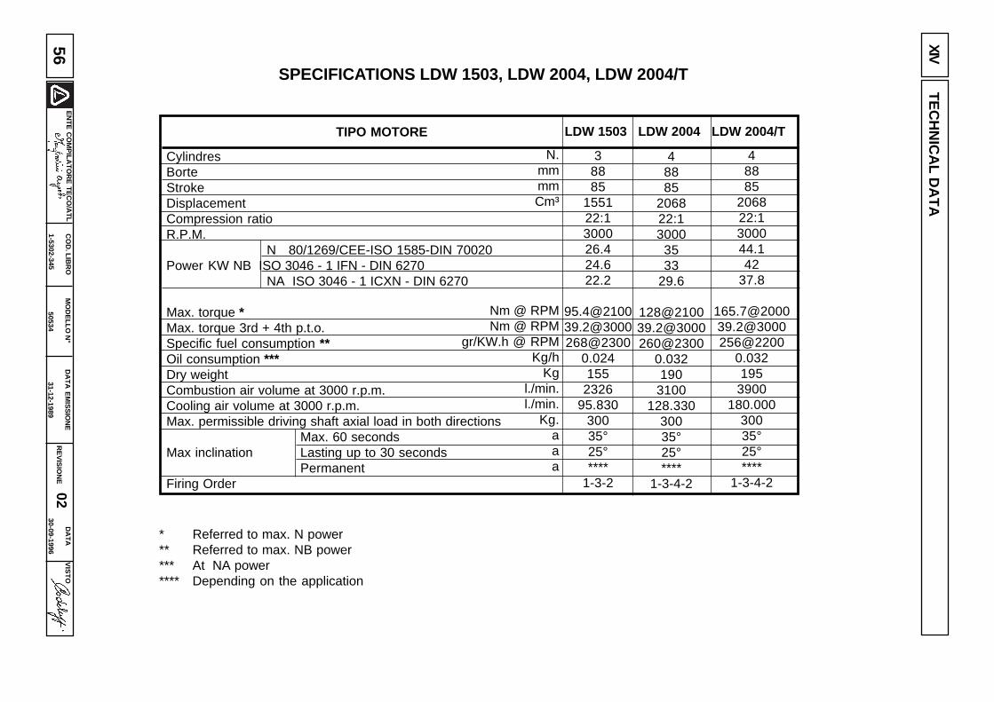
EN
TE
CO
MP
ILAT
OR
E T
EC
O/A
TL
DA
TA
EM
ISS
ION
E
31-12-1989
MO
DE
LLO N
°
50534
CO
D. LIB
RO
1-5302-345
VIS
TO
RE
VIS
ION
E 02
DA
TA
30-09-199656
SPECIFICATIONS LDW 1503, LDW 2004, LDW 2004/TXIV
TE
CH
NIC
AL D
AT
A
LDW 1503 LDW 2004 LDW 2004/TTIPO MOTORE
CylindresBorteStrokeDisplacementCompression ratioR.P.M.
N 80/1269/CEE-ISO 1585-DIN 70020Power KW NB ISO 3046 - 1 IFN - DIN 6270
NA ISO 3046 - 1 ICXN - DIN 6270
Max. torque *Max. torque 3rd + 4th p.t.o.Specific fuel consumption **Oil consumption ***Dry weightCombustion air volume at 3000 r.p.m.Cooling air volume at 3000 r.p.m.Max. permissible driving shaft axial load in both directions
Max. 60 secondsMax inclination Lasting up to 30 seconds
PermanentFiring Order
N.mmmmCm³
Nm @ RPMNm @ RPM
gr/KW.h @ RPMKg/h
Kgl./min.l./min.
Kg.aaa
38885
155122:1300026.424.622.2
[email protected]@3000268@2300
0.024155
232695.830
30035°25°****
1-3-2
48885
206822:13000
3533
29.6
[email protected]@3000260@2300
0.032190
3100128.330
30035°25°****
1-3-4-2
48885
206822:1300044.142
37.8
[email protected]@3000256@2200
0.032195
3900180.000
30035°25°****
1-3-4-2
* Referred to max. N power** Referred to max. NB power*** At NA power**** Depending on the application
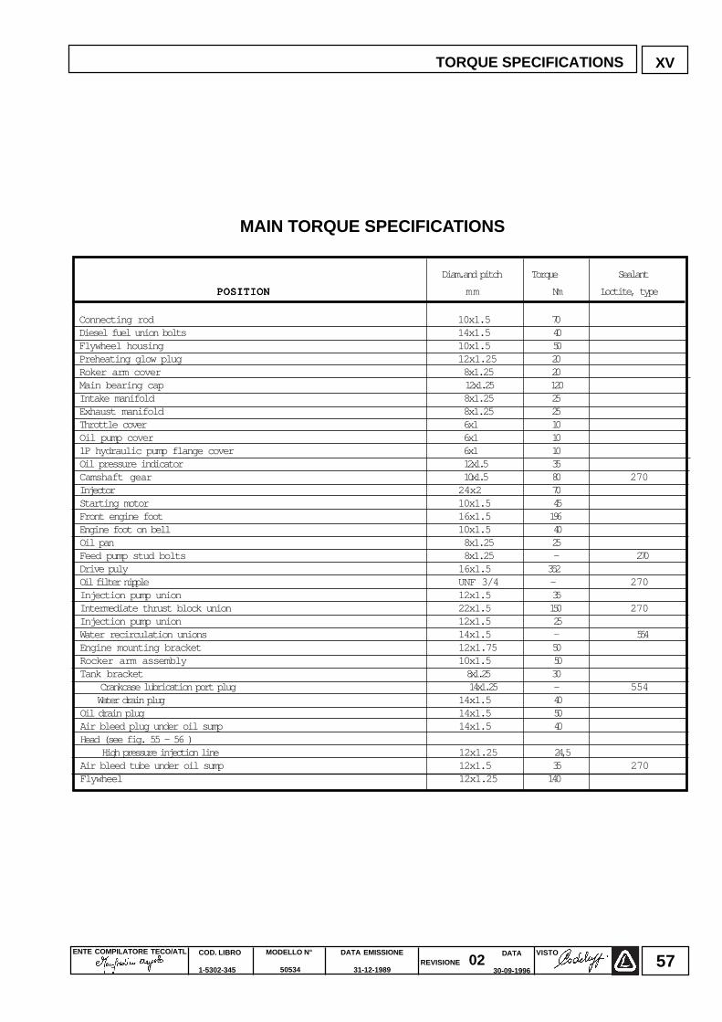
ENTE COMPILATORE TECO/ATL VISTOREVISIONE 02
DATA EMISSIONE
31-12-1989
MODELLO N°
50534
COD. LIBRO
1-5302-345
DATA
30-09-199657
POSITIONPOSITIONPOSITIONPOSITIONPOSITION mm Nm Loctite, type
XV
Diam.and pitch Torque Sealant
Connecting rod 10x1.5 70Diesel fuel union bolts 14x1.5 40Flywheel housing 10x1.5 50Preheating glow plug 12x1.25 20Roker arm cover 8x1.25 20Main bearing cap 12x1.25 1 20Intake manifold 8x1.25 25Exhaust manifold 8x1.25 25Throttle cover 6x1 10Oil pump cover 6x1 101P hydraulic pump flange cover 6x1 10Oil pressure indicator 1 2x1.5 35Camshaft gear 1 0x1.5 80 270Injector 24x2 70Starting motor 10x1.5 45Front engine foot 16x1.5 196Engine foot on bell 10x1.5 40Oil pan 8x1.25 25Feed pump stud bolts 8x1.25 - 270Drive puly 16x1.5 352Oil filter nipple UNF 3/4 - 270Injection pump union 12x1.5 35Intermediate thrust block union 22x1.5 150 270Injection pump union 12x1.5 25Water recirculation unions 14x1.5 - 554Engine mounting bracket 12x1.75 50Rocker arm assembly 10x1.5 50Tank bracket 8 x1.25 3 0
Crankcase lubrication port plug 14x1.25 - 554 Water drain plug 14x1.5 40
Oil drain plug 14x1.5 50Air bleed plug under oil sump 14x1.5 40Head (see fig. 55 - 56 )
High pressure injection line 12x1.25 2 4,5Air bleed tube under oil sump 12x1.5 35 270Flywheel 12x1.25 140
TORQUE SPECIFICATIONS
MAIN TORQUE SPECIFICATIONS
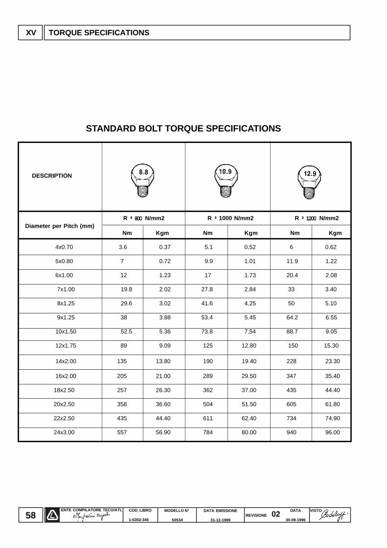
ENTE COMPILATORE TECO/ATL DATA EMISSIONE
31-12-1989
MODELLO N°
50534
COD. LIBRO
1-5302-345
VISTOREVISIONE 02
DATA
30-09-199658
R ³ 800 ³ 800 ³ 800 ³ 800 ³ 800 N/mm2 R ³ ³ ³ ³ ³ 1000 N/mm2 R ³ 1200 ³ 1200 ³ 1200 ³ 1200 ³ 1200 N/mm2 Diameter per Pitch (mm)
Nm Kgm Nm Kgm Nm Kgm
4x0.70 3.6 0.37 5.1 0.52 6 0.62
5x0.80 7 0.72 9.9 1.01 11.9 1.22
6x1.00 12 1.23 17 1.73 20.4 2.08
7x1.00 19.8 2.02 27.8 2.84 33 3.40
8x1.25 29.6 3.02 41.6 4.25 50 5.10
9x1.25 38 3.88 53.4 5.45 64.2 6.55
10x1.50 52.5 5.36 73.8 7,54 88.7 9.05
12x1.75 89 9.09 125 12.80 150 15.30
14x2.00 135 13.80 190 19.40 228 23.30
16x2.00 205 21.00 289 29.50 347 35.40
18x2.50 257 26.30 362 37.00 435 44.40
20x2.50 358 36.60 504 51.50 605 61.80
22x2.50 435 44.40 611 62.40 734 74.90
24x3.00 557 56.90 784 80.00 940 96.00
XV TORQUE SPECIFICATIONS
DESCRIPTION
STANDARD BOLT TORQUE SPECIFICATIONS
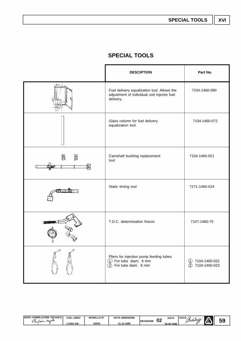
ENTE COMPILATORE TECO/ATL VISTOREVISIONE 02
DATA EMISSIONE
31-12-1989
MODELLO N°
50534
COD. LIBRO
1-5302-345
DATA
30-09-199659
XVI
DESCIPTION Part No.
Fuel delivery equalization tool. Allows the 7104-1460-090adjustment of individual unit injector fueldelivery.
Glass column for fuel delivery 7104-1460-072equalization tool.
Camshaft bushing replacement 7104-1460-021tool
Static timing tool 7271-1460-024
T.D.C. determination fixture. 7107-1460-75
Pliers for injection pump feeding tubes1 For tube diam. 6 mm 1 7104-1460-0222 For tube diam. 8 mm 2 7104-1460-023
SPECIAL TOOLS
SPECIAL TOOLS
ENTE COMPILATORE TECO/ATL DATA EMISSIONE
31-12-1989
MODELLO N°
50534
COD. LIBRO
1-5302-345
VISTOREVISIONE 02
DATA
30-09-199660
NOTE
ENTE COMPILATORE TECO/ATL VISTOREVISIONE 02
DATA EMISSIONE
31-12-1989
MODELLO N°
50534
COD. LIBRO
1-5302-345
DATA
30-09-199661
Air filter restriction switch pag. 11Alternator type Marelli 47,49Camshaft 29Camshaft bushing replacement 30Camshaft end play 32Camshaft journals and bushings in model LDW 1503 29Camshaft journals and bushing in models LDW 2004,LDW 2004/T 29Camshaft removal 29Camshaft timing 30Center main bearings 23Characteristics curves for alternator type Marelli 47, 49Characteristics curves for starting motor type Bosch 50Checking camshaft bushing internal diameter 29Checking dynamic balancer 26Checking injection pump delivery 44Checking main journals and crank pins 25Checking for cooling system leaks 39Characteristics 4Cooling system 38Connecting rod 21Connecting rod alignment 22Connecting rod and piston pin 22Connecting rod/piston assemblies 22Connecting rod weight 21Coolant circulating pump 39Cooling fan 12Crankshaft end play 24Crankshaft for LDW 2004 and LDW 2004/T 26Crankshaft front and rear oil seal 24Crankshaft lubrication ducts 25Crankshaft timing gear 25Cylinder head 14Cylinder class 17Cylinder head gasket 20Cylinder head tightening 20Cylinder head tightening steps 21Cylinder roughness 18Cylinders 17Dimensions for injection pump delivery control yoke adjstment 27Dysassembly/Reassembly 10Dry air cleaner 10Driving pulley 12Dry air cleaner components 11Dynamic balancer 27Electric system 47Exhaust manifold 11Expansion tank and cap 39Flywheel 13Front and rear main bearings 23Front cover 27Fuel feeding/injection circuit 40Fuel feeding pump 40Fuel feeding pump drive rod protrusion 40Fuel filter 40Fuel limiting device 54Fuel system 40Full speed setting in no-load conditions 52Glow plug controller relay 51GR! and GR" hydraulic pump 3rd p.t.o. 32How to prepare the engine for operation 55FHow to reassemble injection pump components 42How to reassemble injection pump feeding tubes 43How to remove injection pump feeding pump feeding tubes 42Hydraulic pump p.t.o. 32Idler gear and hub 27Idling speed setting in no-load conditions 52Index 2Injection pump 41IInjection pum components 41Injection pump control rod 42IInjection pump delivery equalization 43
Injection pump follower 17Injection pump disassemble 41Injection timing check 44Injection timing correction 46Injection timing reference marks 45Injector 46Injector setting 46Instrument for equalizing injection pump delivery 43Intake, exhaust and inject.cam height for mod. LDW 1503 30Intake,exhaust and injection cam height , models LDW 2004,2004/T 30Intake manifold 11Key switch electrical layout 50Lubrication system 35Main bearing and connecting rod big end bering inside diameter 26Maintenance 5Model number and engine identification 3Oil-bath air cleaner 10Oil-bath air cleaner components 10Oil filter cartridge 36Oil pressure adjusting valve 36Oil pressure curve at idling speed 37Oil pump 36Oil pump rotor clearance 36Overall dimensions 7, 8, 9Permanent protection 55Piston 18Piston classes and logo 18Piston position and clearance 20Piston-Refiting 19Piston rings - Clearance between grooves 19Piston rings - Fitting sequence 19Piston rings - End gaps 19Pistons availability 18Piston weight 18Plunger and barrel assembly 44Precombustion chamber 16Preheating glow plug 51Ring feder 12Rocker arm cover 13Rocker arm assembly 14Settings 52Speed governor 27Speed governor counterweights and springs 28Spring for extra fuel suppy at starting 38Standard injection pump delivery setting without dynam. brake 52Standard bolt torque specifications 58Starting motor 50Stop setting 54Storage 55Tank 13Tappet 17Technical data 56Temperature sensor 51Temporary protection 55Test data of injection pump 55Thrust bearings 23Timing angles for checking purposes 31Timing angles for operating puroses 31To check clearance between main bearings and journals 23Turbocharger 33, 34Torque specifications 57Trouble shooting 6Valve guide insertion 15Valve guides and cylinder head 15Valve matirial 15Valve recess and sealing surface 16Valve removal 14Valve/rocker arm clearance 14Valve seats and bore 16Valve spring 15Valve timing check 31Valve timing without considering timing marks 31"V"-belt 12
GENERAL ALPHABETICAL INDEX
Injection pump delivery limitimg and torque adjusting device pag. 52Injection pump delivery setting with engine at the torque dynamo. 53Injection pump non-return valve 42
La Lombardini si riserva il diritto di modificare in qualunque momento i dati contenuti in questa pubblicazione.Lombardini se rèserve le droit de modifier, à n'importe quel moment, les données reportées dans cettepublication.Data reported in this issue can be modified at any time by Lombardini.Lombardini behält sich alle Rechte vor, die hierin enthaltenen Angaben jederzeit zu ändern.La Lombardini se reserva el derecho de modificar sin previo aviso los datos de esta publicación.
ENTE COMPILATORE TECO/ATL VISTOREVISIONE 02
DATA EMISSIONE
31-12-1989
MODELLO N°
50534
COD. LIBRO
1-5302-345
DATA
30-09-199662
42100 Reggio Emilia – Italia - ITALYVia Cav. del Lavoro Adelmo Lombardini, 2 - Cas. Post. 1074Tel. (+39) 0522 3891 - Telex 530003 Motlom I – Telegr.: LombarmotorR.E.A. 227083 - Reg. Impr. RE 10875Cod. fiscale e Partita IVA 01829970357 - CEE Code IT 01829970357E-MAIL: [email protected]: http://www.lombardinifim.it