manuale hd2328 eng 30-03-2007 - delta · pdf filethe hd2328.0 measures the temperature at the...
TRANSCRIPT

Our instruments' quality level is the results of the product continuous development. This can bring about differences between the information written in this manual and the instrument that you have purchased. We cannot entirely exclude errors in the manual, for which we apologize. The data, figures and descriptions contained in this manual cannot be legally asserted. We reserve the right to make changes and corrections without prior notice.
HD2328.0 THERMOCOUPLE THERMOMETER
ENGLISH
REV. 1.4 Mar., 30th 2007

- - 2
Thermocouple Thermometer HD2328

- - 3
HD2328.0 1. Inputs A and B for two thermocouples, with standard miniature connectors.
2. Battery symbol: displays the battery charge level.
3. Function indicators.
4. Secondary display line.
5. DATA/ENTER key: during normal operation displays the maximum (MAX), the minimum (MIN) and the average (AVG) of current measurements; in the menu, confirms the current selection.
6. CLR/ESC key: during normal operation resets the maximum, the minimum and the average of current measurements; in the menu, it resets the value set with the arrows.
7. HOLD/ key: freezes the measurement display during normal operation; in the menu, increases the current value.
8. A-B/MENU key: during normal operation, it displays in the secondary line the difference of the temperatures measured by the probes connected to the inputs A and B; when pressed together with the DATA key, it allows to open the menu.
9. REL/ key: during normal operation enables the relative measurement (displays the difference between the current value and the logged value when the key is pressed); in the menu, decreases the current value.
10. ON-OFF/AUTO-OFF key: turns the instrument on and off; when pressed together with the HOLD key, disables the AutoPowerOff function.
11. MAX (maximum value), MIN (minimum value) and AVG (average value) symbols.
12. Main display line.
13. Line for symbols and comments.
- - 4
TABLE OF CONTENTS 1. GENERAL CHARACTERISTICS............................................................................................................................. 5
2. DESCRIPTION OF THE FUNCTIONS .................................................................................................................... 6
3. THE PROGRAMMING MENU ................................................................................................................................. 9
4. PROBES AND MEASUREMENTS.......................................................................................................................... 10
4.1 TEMPERATURE MEASUREMENT .............................................................................................................................. 10 4.2 CALIBRATION OF THE INSTRUMENT ON LINE WITH THE PROBE(S)............................................................................ 10
4.2.1 Calibration sequence ...................................................................................................................................... 11 5. WARNINGS................................................................................................................................................................ 12
6. INSTRUMENT SIGNALS AND FAULTS .............................................................................................................. 13
7. LOW BATTERY WARNING AND BATTERY REPLACEMENT ..................................................................... 14
7.1 WARNING ABOUT BATTERY USE.............................................................................................................................. 14 8. INSTRUMENT STORAGE....................................................................................................................................... 15
9. NOTES ABOUT WORKING AND OPERATIVE SAFETY ................................................................................. 16
10. TECHNICAL CHARACTERISTICS .................................................................................................................... 17
11. ORDER CODES ....................................................................................................................................................... 19
11.1 THERMOCOUPLE PROBES....................................................................................................................................... 19

- - 5
1. GENERAL CHARACTERISTICS The Thermocouple Thermometer Model HD2328.0 is a portable instrument with two inputs A and B. It measures the temperature of the two input channels, and can calculate the difference between the two channels (A-B). It is fitted with a large LCD display for excellent visualization of the measured data. The Thermometer Model HD2328.0 measures the temperature using immersion, penetration, contact or air probes. The sensor can be a thermocouple chosen among the following types: • Type K • Type J • Type T • Type E The instrument accepts the input of one, or two, thermocouples of the same type (K-J-T-E) even in a different form.
The units of measurement are the following:
1. °C (Celsius degrees) 2. °F (Fahrenheit degrees).
Using the Max, Min and Avg function of this instrument respectively obtains also the maximum, minimum or average values. Other available functions are: • the relative measurement REL; • the HOLD function; • the A-B function; • the automatic turning off which can also be disabled. See chapter 2 for further information. The instrument is provided with the factory calibration. It is also possible to perform a "User Calibration" of instrument+probe (see chapters 3 and 4).

- - 6
2. DESCRIPTION OF THE FUNCTIONS The keyboard of the Thermocouple Thermometer Model HD2328.0 is composed of double-function keys. The function on the key is the "main function", while the one above the key is the "secondary function". When the instrument is in standard measurement mode, the main function is active. In the menu, the secondary function is enabled; press the DATA+(A-B) keys together to open the menu. The pressing of a key is accompanied by a short confirmation "beep": a longer "beep" sounds if the wrong key is pressed. Each key specific function is described in detail below. The HD2328.0 measures the temperature at the two inputs: the temperature measurement at the "A" input is displayed in the main line, while the secondary line shows the value at the "B" input.
This key has two functions:
• ON/OFF: to turn the instrument on press ON, to turn it off press OFF. The turning on enables all display segments for a few seconds, and then the type of calibration enabled (CAL FACT = factory calibration; CAL USER = user calibration).
• AUTO/OFF: the AutoPowerOff function can be disabled by simultaneously pressing this key and the "HOLD" key when turning the instrument on.
If no probe is connected to one of the input connectors, the "BURN" message appears in the corresponding line, that is, in the first line for input "A" and in the second line for input "B".
The instrument has an AutoPowerOff function that automatically turns the instrument off after about 8 minutes if no key is pressed during the intervening time. Press simultaneously the ON/OFF key and the HOLD key to disable this function. In this case, remember to turn the instrument off using the ON/OFF key: disabling of the automatic turning off is shown by the blinking battery symbol.
ON-OFF and AUTO-OFF key
Disabling of the automatic turning off

- - 7
The DATA key is used for the following functions:
• DATA: during normal measurement, by pressing this key once the maximum (MAX) value of the measurements captured by the probes connected to the instrument is displayed, updating it with the acquisition of new samples; - by pressing this key again the minimum (MIN) value is displayed; - by pressing this key a third time the average (AVG) value is displayed. The acquisition frequency is once a second. The MAX, MIN and AVG values remain in the memory until the instrument is on, even after exiting the DATA display function. When the instrument is off, the previously memorized data are cleared. Upon turning on, the instrument automatically starts memorizing the MAX, MIN and AVG values. To reset the previous values and start with a new measurement session, press CLR until the FUNC_CLRD message appears.
• ENTER: once the MENU has been opened with the DATA+UNIT keys, the DATA key will perform the ENTER function and the MENU can be browsed and the displayed parameter confirmed.
The CLR key has two functions:
• CLEAR (CLR): allows to reset the maximum (MAX), minimum (MIN) and average (AVG) value of the captured measurements;
• ESC: once the MENU has been opened with the DATA+UNIT keys, the CLR key will allow to cancel the parameters set using the and arrows.
The HOLD key is used for the following functions:
• HOLD: by pressing this key the current measurement update is stopped and the "HOLD" message will appear in the upper left-hand corner of the display. To return to the current measurement, press the key again.
• : once the MENU has been opened with the DATA+UNIT keys, the key will allow to increase the value of the selected parameter.
Pressed together with the ON/OFF key, during turn on, the AutoPowerOff function is disabled (see the description of the ON/OFF key).
DATA/ENTER key
CLR/ESC key
HOLD/ key

- - 8
The A-B key is used for the following functions:
• A-B: in measurement mode, it displays in the secondary line the difference of the temperatures measured by the probes connected to the inputs A and B, and indicates "ERR" if one of the probes is in error (not connected, faulty or overrange). To end the function, press the key again.
• MENU: in the menu three items can be set (see chapter 3):
1. Selection of the unit of measurement for temperature: °C or °F. 2. Selection of the type of Thermocouple: K, J, T, E. 3. Starting the User calibration procedure.
- the menu is opened by pressing simultaneously DATA+(A-B): the first item of the instrument programming menu will appear;
- use the and arrows (respectively located above the HOLD and REL keys) to modify the displayed value;
- press DATA/ENTER to confirm the modification and go onto the next item; - press CLR/ESC to cancel the modification; - to exit the menu, press the A-B/MENU key again.
The REL key is used for the following functions:
• REL: it displays the difference between the current value and that measured on pressing the key for both measurements: main and secondary. The "REL" message is displayed on the left. To return to the normal measurement, press the key again.
• : once the MENU has been opened with the DATA+(A-B) keys, the key will allow to decrease the value of the selected parameter.
REL/ key
A-B/MENU key

- - 9
3. THE PROGRAMMING MENU To access to the programming menu press simultaneously the DATA+(A-B) keys.
The items to be set are listed in this order:
1. Selection of the unit of measurement: the "SEL_MEAS_UNIT" message is displayed in the comment line. The main line in the center of the display shows the selected unit of measurement: Celsius (°C) or Fahrenheit (°F) degrees.
- use the and arrows (respectively located above the HOLD and REL keys) to modify the type of probe;
- press DATA/ENTER to confirm the modification and go onto the next item; - press CLR/ESC to cancel the modification; - to exit the menu, press the A-B/MENU key again. 2. Selection of the type of Thermocouple: the "SEL" message is displayed in the main line,
while the type of probe is displayed in the comment line; in the secondary line is shown the "tc" message. The types of thermocouple that can be selected are: K, J, T, or E.
- use the and arrows (respectively located above the HOLD and REL keys) to modify the type of thermocouple;
- press DATA/ENTER to confirm the modification and go onto the next item; - press CLR/ESC to cancel the modification; - to exit the menu, press the A-B/MENU key again. 3. Starting the User calibration procedure: the "CAL_MODE" message is displayed in the
comment line, and "FACt" is displayed in the main line. The instrument is provided with the factory ("FACt") calibration. It is also possible to perform a "USER calibration" ("USEr") of instrument+probe. The calibration information is saved in the instrument's memory. The same correction is applied to any probe connected to the input: therefore the "USER calibration" should only be used with the probe used for calibration and not with other probes.
- use the and arrows (respectively located above the HOLD and REL keys) and select USEr, to access the "User Calibration" procedure;
- press DATA/ENTER to confirm the modification; - the "SEL_CHAN" message is displayed in the comment line; - use the and arrows (respectively located above the HOLD and REL keys) to select the
input "A" or "B" in the main line; - press DATA/ENTER to confirm the modification; - the "SEL_MEAS_1/2" message is displayed in the comment line; - use the and arrows (respectively located above the HOLD and REL keys) to select
"0", "1" or "2" in the main line; - press DATA/ENTER to confirm the modification; - press CLR/ESC to cancel the modification; - to exit the menu, press the A-B/MENU key again. See chapter 4 for further explanations.

- - 10
4. PROBES AND MEASUREMENTS
The instrument works with thermocouple probes of type K, J, T, or E.
See chapter 3 for the selection of the type of probe.
The contacts of the thermocouple probe connector are polarized. They must be inserted on the standard miniature socket located on the instrument in the correct direction. These probes are usually marked with a "+" and "–" sign. The user can choose the unit of measurement for display of temperature: °C and °F.
The Thermometer HD2328.0 has two inputs: the temperature for input "A" (see description of the inputs) is displayed in the main line: the temperature for input "B" is displayed in the secondary line. When the "A-B" function is enabled, the relevant differential temperature is displayed in the secondary line. If two probes are used, they must be the same type of thermocouple.
4.1 TEMPERATURE MEASUREMENT
In all versions the thermocouple hot junction is housed in the end part of the probe. The response time for the measurement of the temperature in air is greatly reduced if the air is moving. If the air is still, stir the probe. The response times are longer than those for liquid measurements. The temperature measured by immersion is carried out by inserting the probe in the liquid, in the oven where you wish to perform the measurement; the hot junction is housed in the end part of the probe.
In the temperature measured by penetration the probe tip must be inserted into the material; the hot junction is housed in the end part of the probe.
NOTE: when measuring the temperature on frozen blocks it is convenient to use a mechanical tool to bore a cavity in which to insert the tip probe.
In order to perform a correct contact measurement, the measurement surface must be even and smooth, and the probe must be perpendicular to the measurement plane. So as to obtain the correct measurement, the insertion of a drop of oil or heat-conductive paste between the surface and the probe is useful (do not use water or solvents). This method also improves the response time.
4.2 CALIBRATION OF THE INSTRUMENT ON LINE WITH THE PROBE(S)
To calibrate the probes correctly, a knowledge of and abiding by the physical phenomena on which the measurement is based is fundamental: this is the reason why it is recommended to abide by what is reported below carefully, and only to perform new calibrations if technically proficient and using the suitable equipment. The instrument is provided with the only FACT (factory) calibration. The user is also able to perform a USER calibration of instrument+probe.

- - 11
The calibration information is saved in the instrument's memory. The same correction is applied to any probe that is subsequently connected to the input: therefore the "USER calibration" should only be used with the probe used for calibration and not with other probes. To pass from the user to the factory calibration and back, proceed as follows (see also the menu description in chapter 3): • press simultaneously (A-B)/MENU and DATA/ENTER to open the menu: • press ENTER until the menu item "CAL_MODE" is selected; • use the and arrows (respectively located above the HOLD and REL keys) to select the
type of calibration, FACT or USER; • confirm by pressing DATA/ENTER.
4.2.1 Calibration sequence
Instrument on line with the probe(s) The calibration can be carried out on one or two points that should differ by at least 10°C and be included in the probe functioning range.
1. Insert the probe into a thermostatic bath, the temperature of which is precisely known from a reading taken on a sample reference thermometer. Wait for the measurement to stabilize.
2. Press simultaneously (A-B)/MENU and DATA/ENTER to open the menu. 3. Press DATA/ENTER until the menu item "CAL_MODE" is selected. 4. Use the and arrows (respectively located above the HOLD and REL keys) to select the
USER calibration. 5. Confirm with DATA/ENTER. 6. Use the and arrows (respectively located above the HOLD and REL keys) to select the
input to which the probe being calibrated is connected, choosing the upper connector A or the lower one B.
7. Confirm with DATA/ENTER. 8. The "SEL_MEAS_1/2" message is displayed in the comment line. 9. Use the and arrows to select "1" (first calibration point). 10. Confirm with DATA/ENTER. 11. The "UP DOWN 1st MEAS" message is displayed in the comment line: the instrument display
shows the measured temperature. 12. Use the and arrows to correct the indicated value until it coincides with the value
measured by the sample reference thermometer. 13. Confirm with DATA/ENTER. 14. To exit the procedure without performing the second point, select "0" and press ENTER. 15. To calibrate the second point, select the point "2" using the and arrows. 16. Press DATA/ENTER. 17. The "UP DOWN 2nd MEAS" message is displayed in the comment line. 18. Move the probe to the second thermostatic bath and wait for the measurement to stabilize. 19. The instrument display shows the measured temperature. 20. Use the and arrows to correct the indicated value until it coincides with the value
measured by the sample reference thermometer. 21. Confirm with DATA/ENTER. The procedure is now complete.

- - 12
5. WARNINGS
1. Do not expose the probes to gases or liquids that could corrode the material of the probe. Clean the probe carefully after each measurement.
2. Do not bend the probe connectors or force them upward or downward.
3. Comply with the correct polarity of the probes.
4. Do not bend or force the contacts when inserting the probe connector into the instrument.
5. Do not bend, deform or drop the probes, as this could cause irreparable damage.
6. Always select the most suitable probe for your application.
7. In general, do not use temperature probes in presence of corrosive gases or liquids; the probe external containers are made of AISI 316 or INCONEL stainless steel, while the contact probe containers are made from AISI 316 or INCONEL stainless steel plus silver. Avoid contact between the probe surface and any sticky surface or product that could corrode or damage it.
8. To obtain reliable measurements, temperature variations that are too rapid must be avoided.
9. Temperature probes for surface measurements (contact probes) must be held perpendicular against the surface. Apply oil or heat-conductive paste between the surface and the probe in order to improve contact and reduce reading time. Whatever you do, do not use water or solvent for this purpose. A contact measurement is always very hard to perform. It has high levels of uncertainty and depends on the ability of the operator.
10. Temperature measurements on non-metal surfaces usually require a great deal of time due to the low heat conductivity of non-metal materials.
11. The sensor is not insulated from its external casing; be very careful not to come into contact with live parts (above 48V). This could be extremely dangerous for the instrument as well as for the operator, who could be electrocuted.
12. Avoid taking measurements in presence of high frequency sources, microwave ovens or large magnetic fields; results may not be very reliable.
13. The instrument is water resistant, but should not be immersed in water. Should the instrument fall into the water, check for any water infiltration from the connectors' side. Gently handle the instrument in such a way as to prevent any water infiltration from the connectors' side.

- - 13
6. INSTRUMENT SIGNALS AND FAULTS The following table lists all error indications and information displayed by the instrument and supplied to the user in different operating situations:
Display indications Explanation 1ST_MEAS UP DOWN Correct the first point using the arrows / 2ND_MEAS UP DOWN Correct the second point using the arrows /
BATT TOO LOW
CHNG NOW Indication of insufficient battery charge appearing on turning on. The instrument issues a long beep and turns off. Replace the batteries.
BURN The probe is disconnected or faulty. CAL
LOST Program error: it appears after turning on for a few seconds. Contact the instrument's supplier.
CAL
FACT Factory calibration.
CAL
USER User calibration.
CAL_MODE Calibration mode
ERR This message appears when a wrong function is called: for example, should the A-B key be pressed or the AVG function be enabled when one of the two probes is not connected.
FUNC CLRD Max, min and average values clearing OVER
or
UNDR
Measurement overflow: indicates that the probe is measuring a value exceeding the measuring range.
PLS_EXIT >>> FUNC RES_FOR_FACT ONLY Please exit using ESC >>> function reserved to factory calibration
SEL CHAN Input channel selection SEL MEAS 1/2 Select the first/second calibration point
SEL MEAS UNIT Selection of the unit of measurement SEL_TYPE_TC Selection of the type of thermocouple
SYS
ERR
#
Instrument management program error. Contact the instrument's supplier and communicate the numeric code # reported by the display.
- - 14
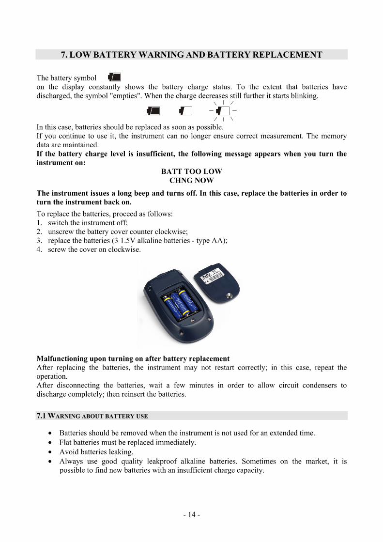
7. LOW BATTERY WARNING AND BATTERY REPLACEMENT The battery symbol on the display constantly shows the battery charge status. To the extent that batteries have discharged, the symbol "empties". When the charge decreases still further it starts blinking.
In this case, batteries should be replaced as soon as possible. If you continue to use it, the instrument can no longer ensure correct measurement. The memory data are maintained. If the battery charge level is insufficient, the following message appears when you turn the instrument on:
BATT TOO LOW CHNG NOW
The instrument issues a long beep and turns off. In this case, replace the batteries in order to turn the instrument back on.
To replace the batteries, proceed as follows: 1. switch the instrument off; 2. unscrew the battery cover counter clockwise; 3. replace the batteries (3 1.5V alkaline batteries - type AA); 4. screw the cover on clockwise.
Malfunctioning upon turning on after battery replacement After replacing the batteries, the instrument may not restart correctly; in this case, repeat the operation. After disconnecting the batteries, wait a few minutes in order to allow circuit condensers to discharge completely; then reinsert the batteries.
7.1 WARNING ABOUT BATTERY USE
• Batteries should be removed when the instrument is not used for an extended time. • Flat batteries must be replaced immediately. • Avoid batteries leaking. • Always use good quality leakproof alkaline batteries. Sometimes on the market, it is
possible to find new batteries with an insufficient charge capacity.

- - 15
8. INSTRUMENT STORAGE Instrument storage conditions:
• Temperature: -25…+65°C. • Humidity: less than 90%RH without condensation. • Do not store the instrument in places where:
• humidity is high; • the instrument may be exposed to direct sunlight; • the instrument may be exposed to a source of high temperature; • the instrument may be exposed to strong vibrations; • the instrument may be exposed to steam, salt or any corrosive gas.
The instrument case is made of ABS plastic: do not use any incompatible solvent for cleaning.
- - 16
9. NOTES ABOUT WORKING AND OPERATIVE SAFETY Authorized use The technical specifications as given in chapter TECHNICAL CHARACTERISTICS must be observed. Only the operation and running of the measuring instrument according to the instructions given in this operating manual is authorized. Any other use is considered unauthorized. General safety instructions This measuring system is constructed and tested in compliance with the EN 61010-1 safety regulations for electronic measuring instruments. It left the factory in a safe and secure technical condition. The smooth functioning and operational safety of the measuring system can only be guaranteed if the generally applicable safety measures and the specific safety instructions in this operating manual are followed during operation. The smooth functioning and operational safety of the instrument can only be guaranteed under the environmental and electrical operating conditions that are in specified in chapter TECHNICAL CHARACTERISTICS. Do not use or store the product in places such as listed below:
• Rapid changes in ambient temperature which may cause condensation. • Corrosive or inflammable gases. • Direct vibration or shock to the instrument. • Excessive induction noise, static electricity, magnetic fields or noise.
If the measuring system was transported from a cold environment to a warm environment, the formation of condensate can impair the functioning of the measuring system. In this event, wait until the temperature of the measuring system reaches room temperature before putting the measuring system back into operation. Obligations of the purchaser The purchaser of this measuring system must ensure that the following laws and guidelines are observed when using dangerous substances:
EEC directives for protective labour legislation National protective labour legislation Safety regulations
- - 17
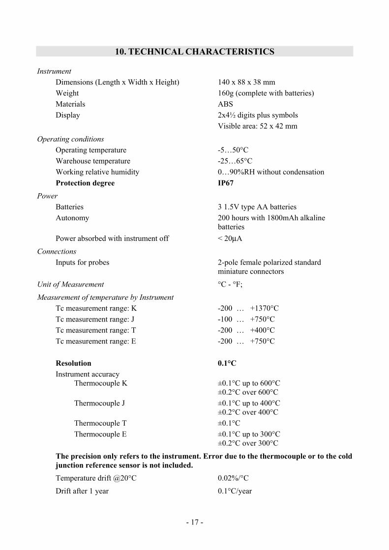
10. TECHNICAL CHARACTERISTICS
Instrument Dimensions (Length x Width x Height) 140 x 88 x 38 mm Weight 160g (complete with batteries) Materials ABS Display 2x4½ digits plus symbols Visible area: 52 x 42 mm
Operating conditions Operating temperature -5…50°C Warehouse temperature -25…65°C Working relative humidity 0…90%RH without condensation Protection degree IP67
Power Batteries 3 1.5V type AA batteries Autonomy 200 hours with 1800mAh alkaline
batteries Power absorbed with instrument off < 20μA
Connections Inputs for probes 2-pole female polarized standard
miniature connectors
Unit of Measurement °C - °F;
Measurement of temperature by Instrument Tc measurement range: K -200 … +1370°C Tc measurement range: J -100 … +750°C Tc measurement range: T -200 … +400°C Tc measurement range: E -200 … +750°C Resolution 0.1°C Instrument accuracy
Thermocouple K ±0.1°C up to 600°C ±0.2°C over 600°C Thermocouple J ±0.1°C up to 400°C ±0.2°C over 400°C Thermocouple T ±0.1°C Thermocouple E ±0.1°C up to 300°C ±0.2°C over 300°C
The precision only refers to the instrument. Error due to the thermocouple or to the cold junction reference sensor is not included. Temperature drift @20°C 0.02%/°C
Drift after 1 year 0.1°C/year

- - 18
Accuracy of the thermocouple probes: The tolerance of a type of thermocouple corresponds to the maximum acceptable departure from the e.m.f. of any thermocouple of that type, with reference junction at 0°C.
The tolerance is expressed in degrees Celsius, preceded by the sign.
The percentage tolerance is given by the ratio between the tolerance expressed in degrees Celsius and the measurement junction temperature, multiplied by one hundred.
The thermocouples conforming to regulations must comply with one of the following tolerance levels, the values of which are reported in the table.
G I (special tolerances) G II (normal tolerances)
The tolerances refer to the expected thermocouple operating temperature, in agreement with the thermoelements' diameter.
Tolerance of the thermocouples:
Type of thermocouple Range °C G I* G II*
K 0 … +1370°C ±1.1°C or ±0.4% ±2.2°C or ±0.75% J 0 … +750°C ±1.1°C or ±0.4% ±2.2°C or ±0.75% T 0 … +400°C ±0.5°C or ±0.4% ±1°C or ±0.75% E 0 … +750°C ±1°C or ±0.4% ±1.7°C or ±0.5%
K** -200 … 0°C --- ±2.2°C or ±2% T** -200 … 0°C --- ±1°C or ±1.5% E** -200 … 0°C --- ±1.7°C or ±1%
* The higher of the two optional limits is the valid one. Example: at 200°C the percentage tolerance for type K thermocouple, tolerance G II, is ±0.75% and is equal to ±1.5°C. Therefore, the limit of ±2.2°C is valid. On the other hand, at 600°C the percentage tolerance is equal to ±4.5°C, and therefore this is the limit to use.
** The thermocouples that meet the limits for temperatures higher than 0°C do not necessarily meet the limits for the range under 0°C.
EMC standard regulations Security EN61000-4-2, EN61010-1 level 3 Electrostatic discharge EN61000-4-2 level 3 Electric fast transients EN61000-4-4 level 3, EN61000-4-5 level 3 Voltage variations EN61000-4-11 Electromagnetic interference susceptibility IEC1000-4-3 Electromagnetic interference emission EN55020 class B

- - 19
11. ORDER CODES HD2328.0 The kit is composed of the instrument HD2328.0 with two inputs, 3 1.5V alkaline
batteries, operating manual, and case. The probes must be ordered separately.
11.1 THERMOCOUPLE PROBES
The thermocouple probes can be connected to all instruments using the standard miniature connector, which can be obtained from the price list.

- - 20
GUARANTEE
GUARANTEE CONDITIONS
All DELTA OHM instruments have been subjected to strict tests and are guaranteed for 24 months from date of purchase. DELTA OHM will repair or replace free of charge any parts which it considers to be inefficient within the guarantee period. Complete replacement is excluded and no request of damages are recognized. The guarantee does not include accidental breakages due to transport, neglect, incorrect use, incorrect connection to voltage different from the contemplated for the instrument. Furthermore the guarantee is not valid if the instrument has been repaired or tampered by unauthorized third parties. The instrument has to be sent to the retailer without transport charge. For all disputes the competent court is the Court of Padua.
The electric and electronic devices with the following symbol cannot be disposed in the public dumps. According to the Directive UE 2002/96/EC, the European users of electric and electronic devices are allowed to give back to the Distributor or Manufacturer the used device at the time of purchasing a new one. The illegal disposing of electric and electronic devices is punished by a pecuniary administrative penalty.
This guarantee must be sent together with the instrument to our service centre. N.B.: Guarantee is valid only if coupon has been correctly filled in all details.
Instrument type HD2328.0
Serial number
RENEWALS
Date Date
Inspector Inspector
Date Date
Inspector Inspector
Date Date
Inspector Inspector
C E C O N F O R M I T Y Safety EN61000-4-2, EN61010-1 LEVEL 3 Electrostatic discharge EN61000-4-2 LEVEL 3
Electric fast transients EN61000-4-4 LEVEL 3 Voltage variations EN61000-4-11
Electromagnetic interference susceptibility IEC1000-4-3
Electromagnetic interference emission EN55020 class B