manuale datalog en - i2m
TRANSCRIPT
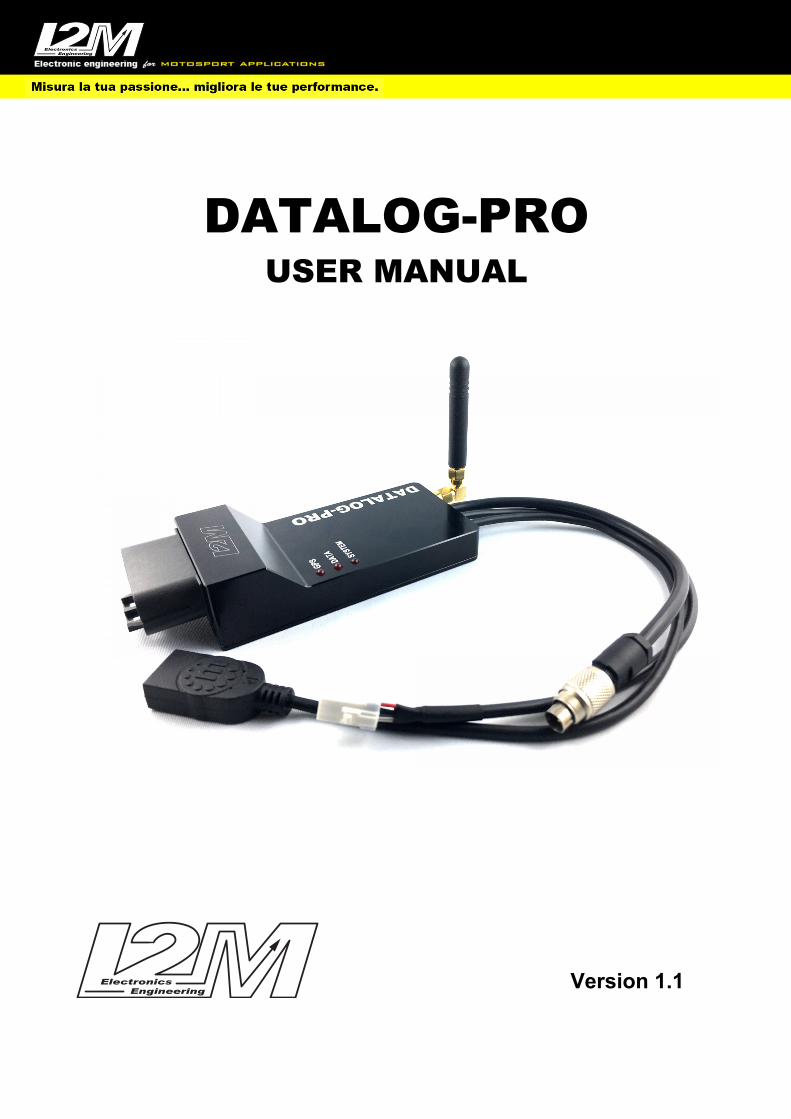
DATALOG-PRO
USER MANUAL
Version 1.1
2
Index Introduction ...................................................................................................................................................... 3
Inside the box: ................................................................................................................................................... 3
Characteristics ................................................................................................................................................... 4
Size .................................................................................................................................................................... 4
DataLog-PRO Installation .................................................................................................................................. 5
GPS installation ................................................................................................................................................. 5
DataLog-PRO inputs .......................................................................................................................................... 6
Led Alarm .......................................................................................................................................................... 9
Programming ..................................................................................................................................................... 9

3
Introduction The Datalog-Pro is a complete data acquisition system that allows you to acquire all useful information for use on the track. Thanks to its 1GHz processor and its 1GB RAM memory this system is able to guarantee all the flexibility needed to adapt to the most modern racing bikes. The DataLog-PRO also incorporates a 433MHz receiver for the reception of signals from our TPMS sensors, a controller for Lambda LSU 4.9 sensors and the management of eight analog inputs, all without additional modules. Thanks to its 1GB internal memory, it is possible to internally save all the acquired data or directly on an external USB key or on both media to keep a safety backup. The DataLog-PRO is provided with its wiring and with the 10 Hz GPS receiver, it is therefore enough to connect it to the battery and to the key signal to start acquiring the first data. Using the Can Bus connection, it is possible to acquire up to 128 fully programmable channels which are added to the 7 analog ones, to acquire the RPM inputs, front and rear speeds and water temperature.
Inside the box: In the DataLog-PRO package you will find:
• DataLog-PRO • Antenna with 90 degree SMA joint for TPMS receiver • GPS receiver • Main wiring • Power / Can Bus patch • Pre-wired 3-way JWPF connector • extension with support for TPMS antenna • 2 TPMS receivers with adapters (optionally for 8.5mm or 11.5mm valves) - KIT version • BOSH LSU 4.9 lambda probe - KIT version
4
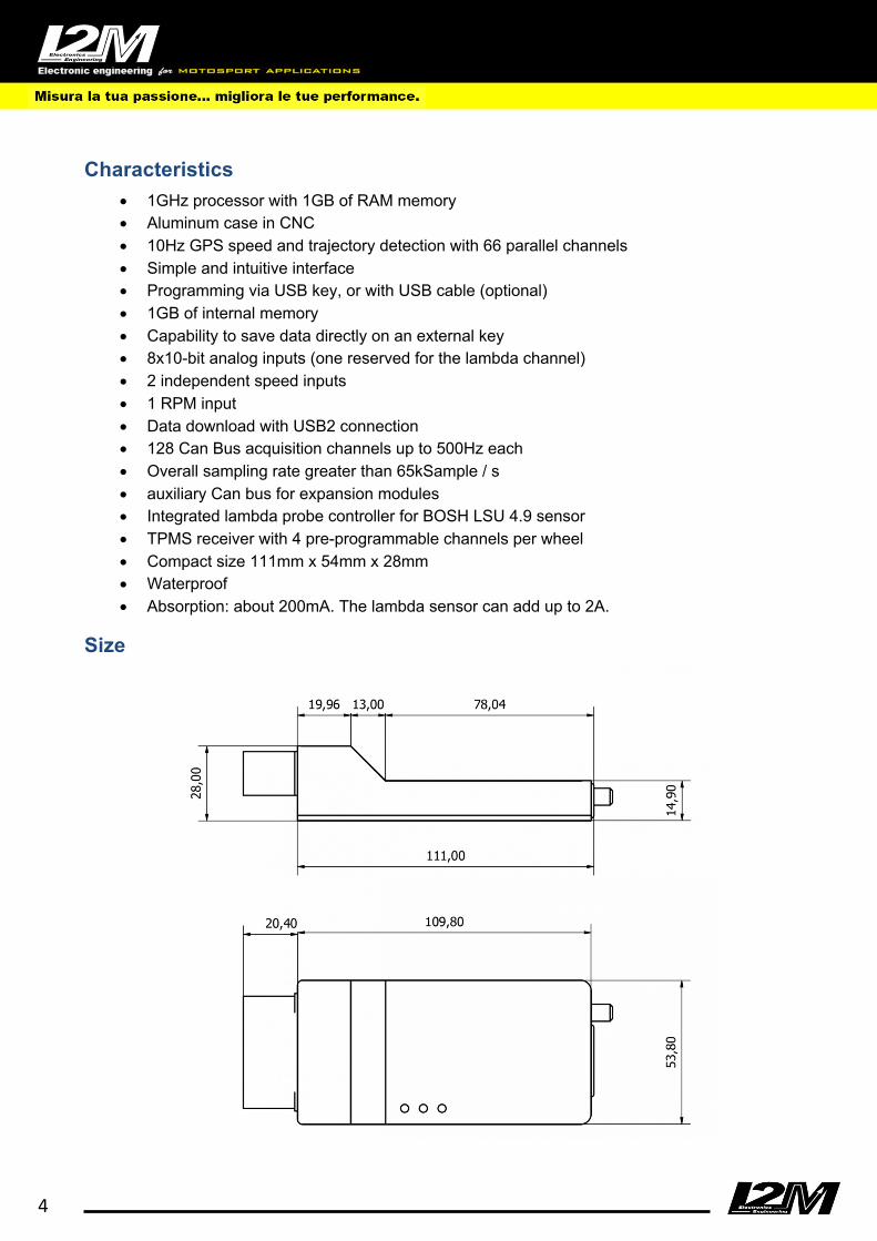
Characteristics
• 1GHz processor with 1GB of RAM memory • Aluminum case in CNC • 10Hz GPS speed and trajectory detection with 66 parallel channels • Simple and intuitive interface • Programming via USB key, or with USB cable (optional) • 1GB of internal memory • Capability to save data directly on an external key • 8x10-bit analog inputs (one reserved for the lambda channel) • 2 independent speed inputs • 1 RPM input • Data download with USB2 connection • 128 Can Bus acquisition channels up to 500Hz each • Overall sampling rate greater than 65kSample / s • auxiliary Can bus for expansion modules • Integrated lambda probe controller for BOSH LSU 4.9 sensor • TPMS receiver with 4 pre-programmable channels per wheel • Compact size 111mm x 54mm x 28mm • Waterproof • Absorption: about 200mA. The lambda sensor can add up to 2A.
Size
5
DataLog-PRO Installation As a first connect a direct power supply to the battery, without removing the protection fuse, then connect the plug & play wiring for your model. If a plug & play harness is not available, use the provided adapter and connect the orange wire to a 12V under-key and then the Can Bus High and Can Bus Low connections if the motorcycle is equipped with Can Bus (the pinout of the connectors is shown later in this manual). The DataLog-PRO has also the connectors for the USB key (exFat formatted only) and for the GPS receiver. The USB sticks, to be recognized by the DataLog-PRO, must have one partition only. ATTENTION: some brand keys, such as some SanDisks for example, often have a second hidden partition containing various utilities, thus becoming incompatible with the DataLog-PRO. The main wiring also integrates the connector for the external channels acquisition. Through the sensor wiring (optional) it is possible to connect several sensors plug & play. However, it is also possible to connect the sensors manually using the pinout shown in this manual. Once the various channels have been connected, it is possible to check their correct functioning through the real-time display by connecting Datalog-PRO via USB to Danas (in this case the optional communication cable is required). DataLog-PRO must NOT be rigidly bound to elements subject to vibrations such as frames and subframes. It is advisable to fix the DataLog-PRO with a simple velcro. Incorrect assembly and consequent continuous exposure to vibrations can damage the DataLog-PRO in a short time, leading to more or less sporadic malfunctions that are difficult to identify during the repairing phase. WARNING: Do not disconnect the DataLog-PRO from direct battery power if the System LED is on or is flashing. Internal memory may be damaged and data will be corrupted.
GPS installation The GPS receiver, in order to receive the best signal, must be positioned horizontally so that it can see as much of the sky as possible. Avoid having metal parts near the receiver that could block the signal. Secure the receiver using double-sided velcro so as not to have a rigid bond between the receiver and the vehicle. DO NOT USE TIES TO LOCK THE GPS. The ideal position is on the tail. The receiver can also be positioned inside the hulls, always horizontally, as long as they are not made of carbon, a material that would shield the signal.
6
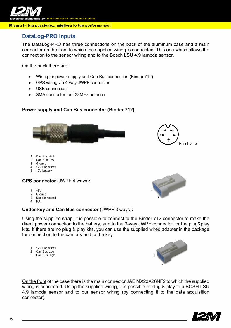
DataLog-PRO inputs The DataLog-PRO has three connections on the back of the aluminum case and a main connector on the front to which the supplied wiring is connected. This one which allows the connection to the sensor wiring and to the Bosch LSU 4.9 lambda sensor. On the back there are:
• Wiring for power supply and Can Bus connection (Binder 712) • GPS wiring via 4-way JWPF connector • USB connection • SMA connector for 433MHz antenna
Power supply and Can Bus connector (Binder 712)
1 Can Bus High 2 Can Bus Low 3 Ground 4 12V under key 5 12V battery
GPS connector (JWPF 4 ways):
1 +5V 2 Ground 3 Not connected 4 RX
Under-key and Can Bus connector (JWPF 3 ways): Using the supplied strap, it is possible to connect to the Binder 712 connector to make the direct power connection to the battery, and to the 3-way JWPF connector for the plug&play kits. If there are no plug & play kits, you can use the supplied wired adapter in the package for connection to the can bus and to the key.
1 12V under key 2 Can Bus Low 3 Can Bus High
On the front of the case there is the main connector JAE MX23A26NF2 to which the supplied wiring is connected. Using the supplied wiring, it is possible to plug & play to a BOSH LSU 4.9 lambda sensor and to our sensor wiring (by connecting it to the data acquisition connector).
1
3

7
Main connector (JAE MX23A26NF2): 1 RPM 2 Rear speed (Vel1) 3 Front speed (Vel2) 4 Under-key (12V lambda) 5 Can Bus Low (2) 6 Can Bus High (2) 7 Analog1 8 Analog2 9 Analog3 10 Analog4 11 lambda5 12 lambda2 13 lambda3 14 USB + (2) 15 USB – (2) 16 Reserved 17 Main ground 18 Analog ground 19 Water temperature input 20 Neutral input 21 Analog6 22 Analog7 23 Analog8 24 5V out sensors 25 lambda1 26 lambda4 Data acquisition connector (COD. MOLEX 33482-1201): Pinout seen from the cable insertion side:
1 12V out under key 2 Analog1 3 Analog2 4 Analog3 5 Analog4 6 Analog ground 7 +5V out 8 Analog5 9 Analog6 10 Analog7 11 Analog8 12 Front speed
CAUTION The 5V out and 12 out power supplies can be used to power any additional sensors that are not directly powered by the vehicle. DO NOT CONNECT the 5Vout or 12V out to a vehicle
1
26
13 14
8
power supply or to an already powered sensor. The analog ground is the reference ground of the analog signals and must always be connected in order to acquire the signals. The DataLog-PRO is equipped with a double power supply, one connected directly to the battery and a one under-key. Once the system is turned off, it does not absorb current from either power supply, the presence of a direct power supply to the battery allows the DataLog-PRO to properly close the files during the shutdown phase. DO NOT alter the DataLog-PRO power supply scheme. Thanks to the stand-by mode (which can be activated during the configuration in Danas) it is possible to keep the GPS switched on even when the DataLog-PRO is switched off. In this phase the GPS will continue to acquire the signals from the satellites in order to minimize FIXING delay. In this phase, the GPS LED on the DataLog-PRO case will flash twice until the end of stand-by. In this phase it is anyway possible to safely disconnect the DataLog-PRO. The system is equipped with the following inputs:
• 8 analog inputs (one reserved for the lambda sensor) • 2 speed inputs • 1 RPM input • 1 water temperature input • 1 battery input (internal) • 1 neutral input • 10 channels multiplexed at 1/10 of the sampling rate (specific for the single bike) • 128 fully configurable Can Channels • 5V output for powering analog sensors not powered by the bike • 12V output for digital sensors not powered by the bike • GPS channels • Lambda probe input • RF input for TPMS signals
In order to have a correct reading of the analog channels it is necessary to connect the analog ground present on the main connector. The DataLog-PRO shares the sensor wiring with the Chrome PRO2, in the case of the DataLog-PRO, however, it is necessary to use and connect the appropriate (analog) ground cable to the battery negative pole. Analogs 1-8: these are 10-bit 0-5V analog inputs and are available to monitor, for example, the opening of the gas or special sensors such as those for brake pressure or suspensions potentiometers, tire temperature sensors etc ... Analog number 5 is reserved for reading the Lambda signal (internal). RPM: this input is specially designed to monitor the number of engine revolutions which can be obtained reading the signal from the control unit to the dashboard. Attention, the number of impulses that are sent for each engine revolution varies from bike to bike and therefore MUST BE CONFIGURED using the appropriate menu. The system accepts input signals on this pin up to 20V. This input is not used with motorcycles equipped with Can-Bus. SPEED: two 0-5V speed signals can be connected to the speed inputs, for example from each one of the two wheels. The signals can come from suitable inductive sensors or, in the
9
case of the rear wheel, directly from the factory sensor. This sensor counts the number of revolutions of the pinion or, in some cases, of an internal shaft directly connected to the pinion. Attention, the number of impulses that this sensor gives for each revolution of the pinion varies from bike to bike and therefore MUST BE CONFIGURED using the appropriate menu. This input is not used with motorcycles equipped with Can-Bus. Water temperature: it is a 0-5V input dedicated to reading the water temperature. The system is preconfigured for some standard temperature sensors. The input can tolerate voltages up to 12V. This input is not used with motorcycles equipped with Can-Bus. Neutral input: this input is reserved for reading the signal coming from the road sensor. The voltage values corresponding to the different gear must be configured via Danas. This input is not used with motorcycles equipped with Can-Bus. Led Alarm The DataLog-PRO has three signaling LEDs called GPS, DATA and SYSTEM. The GPS led partially replicates the signaling of the GPS antenna:
• Off: the gps antenna is not connected • On: the GPS antenna is connected but the satellites have not yet been FIXed • Single flash: the satellites have been FIXed • Double flash: the system is OFF and the GPS is in stand-by
The DATA led gives indications on the memory status and data acquisition: • Green: the system has detected the connection of a USB key or a communication cable • Blinking green: the system is recording • Red: the system has detected an error while writing the file (memory disconnected,
memory full, internal error)
The SYSTEM led gives information on the system status: • Double flash red: the system is active • Double flash green: the system is active and a Can Bus signal is present • Red: the system is shutting down
During the turn on phase, the three LEDs light up sequentially, flashing until the initialization is completed. Programming The DataLog-PRO can be programmed either through the use of the optional connection cable or simply through the use of a USB or USB2 key (exFat formatted only). When turned on, the system searches for the new configuration files in a folder on the USB key named Datalog_New_Settings (the folder is automatically created on the key if not present when the system turns on), once this first phase is done, the current configuration is saved in the Datalog_Current_Settings folder. The configuration files are written using the specific function in the Danas software. The files can then be read or written to a key (within the appropriate folders) or transferred to the DataLog-PRO via the programming cable.

10
In Danas, in the online menu select the Configure DataLog-PRO function to display the window shown in the figure.
Using the Import and Export keys, it is possible to import and export the configuration files to be written to or read from a USB key (the files must be written in the Datalog_New_Settings folder to be read by the DataLog-PRO). For programming via the programming cable, you must first select the virtual port corresponding to the programming cable. The programming cable is based on FTDI technology (https://www.ftdichip.com) which generates a virtual COM port. Once the connection is made, the keys for receiving and transmitting data via Usb are enabled. The programming windows has various Tabs: Within the General Tab you can choose:
• acquisition frequency: Indicates the acquisition frequency for the analog channels and the RPM, front and rear speed channels and consequently the frequency of the multiplexed channels specific for the various bikes (refer to the manual of the Chrome plug & play kits with which the DataLog-PRO shares configurations).
• Minimum speed: by choosing rear speed or GPS speed as the auto-start channel, this parameter indicates the minimum speed beyond which recording is enabled. The threshold must be respected for at least 3 seconds, both for the start and for the stop of the recording
• Auto-start channel: indicates the channel that triggers the start of data recording. It can be the GPS speed, the rear speed or the rpm (in this case the condition for recording is the RPM > 900 for at least three seconds, and similarly at least three seconds below this threshold for stopping the recording).
• File Prefix: Indicates the prefix that is added to the file names to identify the pilot. The prefix must not contain spaces.

11
• Standby duration after shutdown: in order to minimize the GPS signal FIX delay, it is possible to leave the GPS on for “x” hours after the system is turned off.
• Type of motorcycle: by choosing the motorcycle from those configured in the list, some configurations are automatically set, they can be changed manually in any case.
• Data saving: allows you to choose whether the data must be stored in the 1GB internal memory (and accessible via the programming cable) or be saved directly on an external USB2 key (exFat formatted only) or saved on both media. The internal saving, even in the case of saving on USB, allows you to have a backup in case, for example, the USB key disconnects due to vibrations. Warning: the writing speed of the key and its size are fundamental parameters to avoid problems during recording. We recommend compact USB sticks 2 that guarantee a write speed higher than 20 Mbps
• Restore factory conditions: this function reinitializes the system.
Within the Inputs Tab you can choose:
• Digital input: indicates which input between RPM, Front speed and Rear speed is being configured
• Number of pulses: indicates the number of pulses that are read by the sensor for each rotation of the crankshaft (per RPM) or of the pinion (if the speed sensor is on the pinion) or of the wheel (if the speed sensor directly reads the wheel rotation)
• Pinion teeth: indicates the number of pinion teeth. This field must be set to 1 in the case of front speed or if the sensor directly reads the rotation of the wheel
• Crown teeth: indicates the number of teeth in the crown. This field must be set to 1 in the case of front speed or if the sensor directly reads the rotation of the wheel
• Analog input: indicates which of the analog inputs is being configured • Minimum value: indicates the value of the analog channel at 0V in input • Maximum value: it indicates the value of the analog channel at 5V in input. • Sensor type: indicates whether the input is linear or is associated to one of the parametric
models • Import from default session: through this function it is possible to import the names and
channels minimum and maximum values directly from the default session currently open in Danas.
• Rpm / pinion ratio 1,2,3,4,5,6: in the case of motorbikes without can bus, in which the gear is calculated from the rpm / speed ratio, it is possible to specify the ratios for each gear (it is possible to obtain those from Danas).
• Configure analog inputs automatically: it is possible to configure some sensors automatically such as potentiometers, our infrared brake pressure sensor, a temperature sensor or a TPS

12
channel. Select the channel you want to configure in the window that appears by pressing the button. Choose the type of sensor and follow the steps indicated. This function is available only if the DataLog-PRO is connected via a programming cable.
• Configure parametric sensors: using this function it is possible to define the characteristics of the parametric filters available through the window shown in the figure. For each characteristic it is possible to define the number of points that define the curve and the value of each point
Within the TPMS and Can Bus Tab you can choose:
• Front sensor in use: the DataLog-PRO allows you to keep in memory the ID of four sensors
associated to the front wheel. This function chooses which sensor is the one currently in use • Front Sensor ID: Indicates the 7-digit ID code associated to the front sensor in use • Rear sensor in use: the DataLog-PRO allows you to keep in memory the ID of four sensors
associated to the rear wheel. This function chooses which sensor is the one currently in use • Rear Sensor ID: Indicates the 7-digit ID code associated to the rear sensor in use • Can bus baud rate: indicates the can bus baud rate to which the DataLog-PRO is connected.
By selecting the type of motorcycle this value is pre-configured. Using a value other than the correct one will make reading the can bus data impossible.
• Neutral / gear voltage 1,2,3,4,5,6: if the neutral input for the gear channel is selected, in these fields it is possible to enter the voltage value associated to each gear and read by the gearbox position sensor via the connection with the neutral input.
• Configure can bus channels: using this function it is possible to configure different channels of the DataLog-PRO, using the window shown in the figure.

13
For each active channel it is possible to choose different parameters:
• Name (only for channels can1-can128) • Type: the channels can be default channels and therefore preconfigured and not modifiable
or associated to a particular analog input or finally acquired via the can bus. • Frequency: indicates the sampling frequency of the channel. It can only be modified for
programmable can bus channels can1-can128. You can choose 10,100,200 or 500Hz • ID: indicates the address of the Can Bus phrase from which the channel in question is read.
The ID is in DECIMAL format (NOT HEXADECIMAL). • Byte1: indicates the least significant byte associated to the can bus channel • Byte2: indicates the most significant byte associated to the can bus channel • Mask: indicates the 16-bit mask associated to the channel. The read value is put in AND with
the mask. • Division: indicates the division associated to the can bus value read before applying gain and
offset • Gain: indicates the gain associated to the can bus value read • Offset: indicates the offset associated to the can bus channel read • Minimum: if the Type associated to the channel is an analog input, this parameter indicates
the value of the channel when the input is at 0V • Maximum: if the Type associated to the channel is an analog input, this parameter indicates
the value of the channel when the input is at 5V • Sensor type: if the type associated to the channel is an analog input, using this parameter it
is possible to establish whether the input is linear or is associated to one of the parametric models set in the Inputs Tab.
• Sign: if the Type associated to the channel is a can bus input, it is possible to choose whether the channel is an UNSIGNED, SIGNED8 or SIGNED16, in the last two cases the Mask and Division parameters are not applied.
• Byte multi: if the Type associated to the channel is a can bus input, it is possible to manage multiplexed can bus values. With this parameter you can activate this possibility and choose which byte indicates the field indicating the multiplex index
• Multi value: if the Type associated to the channel is a can bus input and the multiplexing function is active, this parameter indicates the value that must be read in the multi byte in order to acquire the associated channel.
14
The channels currently read by the DataLog-PRO are displayed in real-time in the Online Tab. In order to activate this function, it is necessary to be connected to the DataLog-PRO through the programming wiring. The Download Tab displays the files currently present in the DataLog-PRO, for each file the circuit, date, start time, size and progressive number associated to each session are indicated.
• Update: this key can be used to update the display of the files present in the DataLog-PRO • Download to key: with this function the selected files are downloaded to the key, it is therefore
necessary to connect a USB key (exFat formatted only) and the programming cable via a hub.
• Delete: with this function the selected files are deleted • Delete all: with this function all files are deleted • Memory occupied: the bar indicates the percentage of memory currently occupied in the
DataLog-PRO
Within the Info Tab you can choose: • Software version: Indicates the current software version of the DataLog-PRO • Firmware version: Indicates the firmware version currently present in the DataLog-PRO • Session number: The DataLog-PRO assigns a progressive number to each session so that
they can always be sorted chronologically even if the GPS has not been FIXed (and therefore the date and time is not present). The session number indicates the number currently in use
• Reset number of sessions: this function allows you to reset the session number currently in use.
• Update software: this function allows you to update the DataLog-PRO software, the files for updating must be placed inside a USB key (exFat formatted only) connected to the DataLog-Pro. The programming cable must then be connected via a hub. Only the files must be present on the key, they must NOT be contained in any folder
• Update firmware: this function allows you to update the firmware of the DataLog-PRO, the files for updating must be placed inside a USB key (exFat formatted only) connected to the DataLog-Pro. The programming cable must then be connected via a hub. Only the files must be present on the key, they must NOT be contained in any folder