manual - uhlenbrock1.3 special modules for intelligent extension of the desk 6 1.4 tc-edit – the...
TRANSCRIPT

On the Wire without Wire
Manual Assembly and Basic Operation

2
Track Control
Contents 1. Track-Control - the Track plan control panel 4
1.1 Description 4 1.2 Only a few different module types are needed 5 1.3 Special modules for intelligent extension of the desk 6 1.4 TC-Edit – the design and configuration software for the desk 7
2. Assembly 8 2.1 Building the Desk 8 2.2 Connecting the panel 11
3. Programming of the keys - ingeniously simply 12 3.1 Before you begin! 12 3.2 Programming the turnout PCBs 13
3.2.1 The different turnout images 13 3.2.2 Programming for turnouts with a motor 14 3.2.3 Programming for crossing switches with a motor 15 3.2.4 Programming for turnouts with two motors 16 3.2.5 Programming of switch PCBs for switching applications 17 3.2.6 Programming of turnout PCBs for uncouplers 17
3.3 Programming of Signal PCBs 18 3.3.1 The different signal images 18 3.3.2 Programming of Signal PCBs 18
4. The individual Components 19 4.1 The Interface Module 19 4.2 The Connecting PCBs 19 4.3 The turnout module 69 220 19 4.4 Signal Module 69 230 20 4.5 Route Memory 60 240 21 4.6 Train Number Display 69 250 21
4.6.1 Programming of the module with keys 21 4.6.2.1 Display of basic functions and switching operation 22 4.6.2.2 Display of automatic operations 22 4.6.2.3 The different Displays 22 4.6.2.4 Display Mode 22 4.6.2.5 Time Display 23
4.6.3 Configuring the Screen display memory 23 4.7 Track-control speed controller with DirectDrive function 24
4.7.1 Description 24 4.7.2 Connection 24 4.7.3 Control Elements 24
4.7.3.1 Rotary Knob 24 4.7.3.2 Number keys to input addresses 24 4.7.3.3 Function keys [f1] to [f8] 24 4.7.3.4 [f9...]-key 24 4.7.3.5 The [lok#]-Key 25 4.7.3.6 Meaning of LEDs 25
4.7.4 Locomotive selection by address input 25 4.7.5 Locomotive selection by DirectDrive 26
4.7.5.1 Locomotive selection from a LISSY receiver 26 4.7.5.2 Locomotive selection via a Track-control signal or track key module 26

3
Track Control4.7.6 Locomotive selection by Dispatch mode 27
4.7.6.1 Taking over a Locomotive address from the Dispatch memory 27 4.7.6.2 Hand over a Locomotive address to the Dispatch memory 27
4.7.7 Shunting mode 27 4.7.8 Turn track power back on 27 4.7.9 Speed controller mode change 28
5. Track-control in the analog layouts 28 5.1 Requirements 28 5.2 Connection of the LocoNet interface 28 5.3 Track-control module to analog enterprise change over 28 5.4 Connection of the Switch Module 29 5.5 Red indication of occupied track sections 29 5.6 Saving of the operating States 29
Appendix 30 What is LISSY? 30
Product overview 30 Contents of the two sets 30 Hotline 31
All trademarks used are registered by the respective companies.

4
Track Control
1. Track-Control - the Track plan control panel 1.1 Description Efficient and inexpensive Our desk panel, Track-control, is based on the Siemens panel DrS2, which has been in service in railways since the 60's. Functionality was adapted to suit model railroading. Operation is more convenient and the overview is better. In principle all kinds of tracks that are available can be represented. All switching functions used in model railway can be activated by pressing a key. Track-Control can be used independently of the track system used to control the model railway of any gauge. It is suitable for all LocoNet equipped digital controllers and accessory equipment in most model railway environments. As in the prototype the Track-Control consists of stylized rectangular segments. Each segment is 40 x 25 x 12 mm. Illumination of the symbols is done by multi color LEDs. The Track-Control can be developed very simply with minimum expenditure by use of segmented construction. With the frameless bench mounting each controller’s desk can be composed of only few different items resulting in a price effective system. The individual Control desk elements are easily assembled - there are no cables and soldering is passé! Changes and extensions are possible at any time. The structure’s height is only 12 mm! Turnouts, signals, lighting, uncoupler and our lighting installation IntelliLight can be switched. Double crossing slips with only one motor are also correctly indicated. Auxiliary keys can be used to control multi-function signals. There is a dynamic allocation of warning signals to the home signals as a function of the traffic. Set routes can be indicated. A red indicator represents that the field is occupied. A Route Memory with space for over 2000 individual instructions serves for switching routes. These can be called up with start and end keys. Programmed routes are illuminated in yellow. Routes can mutually lock each other out, e.g. as safety device for crossing routes. The Train Number display is used to indicate the locomotive address, train category, driving direction, speed and the block status that a LISSY receiver has determined. Information is always indicated about the locomotive which last passed the LISSY receiver (e.g. at the exit track of the shadow station). In the controller’s desk has an integratable speed controller with 16 special functions and the light function. Because of DirectDrive, locomotive addresses or names need never be noted again! Locomotives recognized by LISSY can be taken over by the speed controller with the simple push of a button. TC-Edit, the program for the controller’s desk, makes planning and configuration of a desk really simple for you (see chapter 1.4 TC-Edit description). Even without TC-Edit the configuration of the controller’s desk is ingeniously simple: press a key and then switch a turnout or signal. Done!

5
Track Control
1.2 Only a few different module types are needed Every module has a 25 x 40 x 12 mm housings and one electronic PCB. Plastic Segment 69 100 The plastic segments are usable for all modules. Tinted diffusers distribute the light, key caps for modules with switching functions, connecting plugs for fixing the individual segments to each other and on the base board are included. With different symbol stickers and matching programming only 5 different electronic PCBs are needed to develop a complex desk. Cross Connection PCB 69 210 Connects the individual rows of the controller’s desk to each other, required at least once per row, yellow route indication and red occupied indicator. Connecting PCB without illumination 69 212 Connects individual segments in a row of the controller’s desk to each other if in these segments have no operating function. Connecting PCB with illuminating 69 214 Connects the individual segments in a row of the controller’s desk to each other. With yellow route indication and red occupied indicator. Switch PCB 69 220 For switching of turnouts, double crossing slips, single crossing slips, three-way turnouts, lighting and uncoupling tracks. Correct indication of crossing slips, even if these have only one motor. With occupation indication for the turnout. Signal PCB 69 230 Used for main, shunting, entry, exit and warning signals and also route start and route end and auxiliary keys.

6
Track Control
1.3 Special modules for intelligent extension of the desk With the following modules the controller’s desk becomes real fun! Route Memory 69 240 Segment for inserting into the controller’s desk. Stores up to 2000 route switching commands which can be called by the controller’s desk. Call routes via start and end keys. Train Number Display 69 250 The train number display can be inserted into the controller’s desk as a segment. With installation of the LISSY system the numbers of the trains which pass the assigned LISSY receiver are then indicated, (e.g. at the driving out track of the shade station). Speed Controller with DirectDrive 69 300 The speed controller is as large as three desk segments and can be easily integrated into the controller’s desk. It switches 16 special functions and the light function. With large rotary regulator with reversing switch. Besides the normal driving functions it has another special characteristic: the DirectDrive function. That means it can take control of a locomotive which passed a LISSY receiver by the simple push of a button on the speed controller without having to know the locomotive address.

7
Track Control
1.4 TC-Edit – the design and configuration software for the desk TC-Edit, the program for the controller’s desk really simplifies the planning and configuration of the control desk. Planning Software The individual control desk elements are arranged with the mouse on the work space. The finished track plan is quickly developed from the individual symbols with easy mouse clicks. In addition a parts list and connecting plan are generated automatically. These can be printed out to help you with purchase and assembly. Configuration Software The program for configuring the individual segments automatically executes many tasks, which would otherwise have to be programmed manually. In addition the more complex desk functions and settings of the desk can be programmed with the program. The individual steps are clearly shown and provide a simple overview. Functionality • Simple programming of individual elements • Automatic assignment of all switching and feedback addresses • Swapping of turnout position indicators • Red illumination for occupied indicator • Barring of the key function of occupied turnouts • Flashing of changing turnouts • Configuration of routes • Yellow route illumination • Activation of routes by start/end keys • Switching of multi-function signals by auxiliary keys • Dynamic allocation of the warning signals to the home signal in the route • Configuration of the train number display • Configuration of the speed controller • Brightness control of the LEDs • Setting of key locks (child safe device) • Printing of module and route configuration for documentation NOTE: The operating instructions for TC-Edit are on the program CD.

8
Track Control
Molding recess
2. Assembly The planning of your controller’s desk can either be done by hand or with planning and configuration program TC-Edit which is provided on the CD. From a control desk developed in the TC-Edit you can generate a track plan, a connecting plan and a parts list to assist with purchasing the components. NOTE: Ensure the correct connecting PCBs and cross connecting PCBs are used so that the individual elements and rows are electrically connected with one another. It is best to select the row for the connecting lead so that the plug is later covered by a segment. That looks more attractive.
2.1 Building the Desk When you have completed the plan of your controller’s desk you can assemble it according to your track plan. Preparing the work space Start a new work space which should be at least twice as large as the planned control desk. Use the track plan and if available, the connecting plan, as construction aid.
Track layout Connection diagram Preparation of the plastic elements Firstly put the tinted diffusers into the plastic segments. The diffusers must lock in place flush with top surface of the plastic segments. Then stick the foils in place according to the track plan. Press the foils down only lightly. Hint: All foils should be aligned correctly around the edges of each segment. Turn the plastic segments so that molding recesses later face inwards. Don not stick the foils for segments which are used for uncouplers, route memory or free standing warning signals till after the programming of the control desk as these would otherwise cover the LEDs or keys.

9
Track Control On fields with descriptors stick the narrow foils on first. If you wish text other than that provided you can either mark the narrow empty foils with marker or use labels with the appropriate text. Stick window foil in place after that. Now lay out all the plastic segments according to the track plan. Preparation of the electronic PCBs Now plug the required PCBs together according to track or connecting plan. Note: The lateral pins must always point to the left and the vertical pins of the cross joiners always point upward. Plug the thin plug from the enclosed three core lead on the middle three pins of a vacant row connector. Note the orientation of the plug (see the colour coding in the accompanying photo)! HINT: It is best to select a row where the plug is later covered by a segment. That simply looks more attractive.

10
Track Control Place the plastic segments and the assembled PCBs beside one another. Completion Now take the first four plastic segments, starting in the lower right corner of the control desk, and insert the keys if necessarily. Insert the PCBs into the plastic segments where needed. Now you can set up these 4 segments and physically connect them in the center with a connector plug. Note: The connecting plugs must be attached at the segment crossings so that the mounting lug points either up or down.
Now you can add the next plastic segments. if necessary add the connector plug for each block of four. Continue, until you have the desk assembled completely.

11
Track Control Since the plug connectors do not only hold the plastic segments, but also fix the diffusers and PCBs into the segments. Halved plug connectors are finally attached at the outside segments. If necessary the lugs can be attached outwards so that the desk can be screwed onto the base board. Now you can cut off all connecter pins that protrude outwards with a side cutter. 2.2 Connecting the panel Connect the thick plug of the control desk lead with the appropriate pins of the module. The plug is keyed and can only be inserted correctly. Connect the module to separate 16V AC transformer and connect the provided LocoNet cable to the LocoNet T socket of the Intellibox. The desk is now complete and the individual segments can be programmed! Ensure that you provide a stable base board for the installation of the desk.
12
Track Control
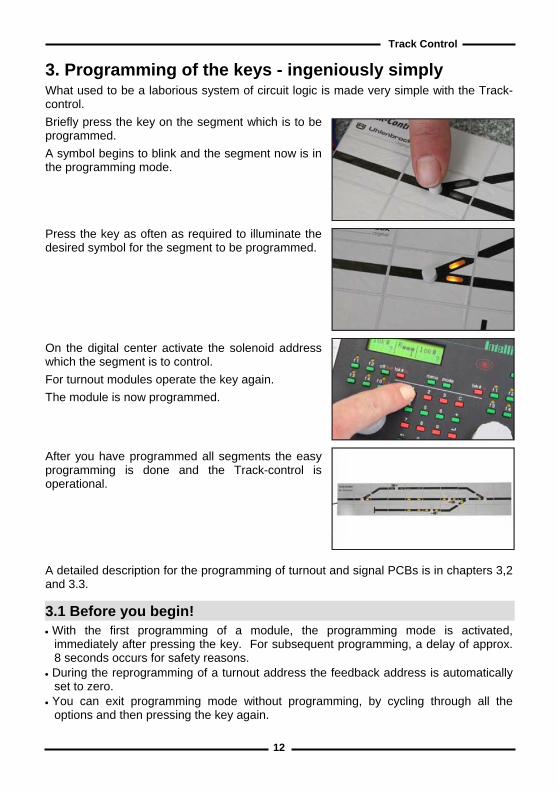
3. Programming of the keys - ingeniously simply What used to be a laborious system of circuit logic is made very simple with the Track-control. Briefly press the key on the segment which is to be programmed. A symbol begins to blink and the segment now is in the programming mode.
Press the key as often as required to illuminate the desired symbol for the segment to be programmed. On the digital center activate the solenoid address which the segment is to control. For turnout modules operate the key again. The module is now programmed. After you have programmed all segments the easy programming is done and the Track-control is operational. A detailed description for the programming of turnout and signal PCBs is in chapters 3,2 and 3.3.
3.1 Before you begin! • With the first programming of a module, the programming mode is activated,
immediately after pressing the key. For subsequent programming, a delay of approx. 8 seconds occurs for safety reasons.
• During the reprogramming of a turnout address the feedback address is automatically set to zero.
• You can exit programming mode without programming, by cycling through all the options and then pressing the key again.

13
Track Control
3.2 Programming the turnout PCBs 3.2.1 The different turnout images
Position Description Indicators Sticker 0 Turnout top-left
Programming procedure 3.2.2 for turnouts with a motor
1 Turnout bottom-left
Programming procedure 3.2.2 for turnouts with a motor
2 Turnout bottom-right
Programming procedure 3.2.2 for turnouts with a motor
3 Turnout top-right
Programming procedure 3.2.2 for turnouts with a motor
4 Double Crossing Slip bottom-right / top-left
with a motor Programming procedure 3.2.3 for crossing slips with a motor
5 Double Crossing Slip bottom-left / top-right with a motor Programming procedure 3.2.3 for crossing slip with a motor
6 Double Crossing Slip (large) with a motor Programming procedure 3.2.3 for crossing switches with a motor

14
Track Control
Position Description Indicators Sticker 7 Double Crossing Slip bottom-left / top-
right with two motors Programming procedure 3.2.4 for turnouts with two motors
8 Double Crossing Slip top-right / bottom-left with two drives Programming procedure 3.2.4 for turnouts with two motors
9 Double Crossing Slip (large) with two motors Programming procedure 3.2.4 for turnouts with two motors
10 Y-turnout on the left Programming procedures 3.2.2 for turnouts with a motor
11 Y- turnout on the right
Programming procedures 3.2.2 for turnouts with a motor
12 Three-way turnout to the left
Programming procedures 3.2.4 for turnouts with two motors
13 Three-way turnout on the right
Programming procedures 3.2.4 for turnouts with two motors
14 Switching application with left indicator
(e.g. for layout lighting) Programming procedures 3.2.5 for switching applications
15 Switching application with right indicator (e.g. for layout lighting) programming procedures 3.2.5 for switching applications
16 Uncoupler Programming procedure 3.2.6 for Uncoupler
3.2.2 Programming for turnouts with a motor 1. Entering Programming mode
Hold the key on the segment to be programmed pressed until all LEDs flash. 2. Selecting the Indication
Press the module key as often as needed (according to the "position" number in the table of turnout pictures) to illuminate the desired turnout picture. All LEDs belonging to the appropriate turnout flash yellow while the module awaits the allocation of a turnout address.

15
Track Control3. Assign a Turnout Address
On the control center switch the turnout address which is to be assigned to this module to red or green switch. All of the module’s LEDs flash red if the module expects the allocation of a feedback address. If no feedback is wanted press module key in order to terminate programming without the assignment of a feedback address.
4. Assign a Feedback Address To assign a feedback address switch solenoid address (=feedback address) on the control center which corresponds to the desired feedback address for the turnout. The programming mode is exited automatically. The module is operational. The module now indicates red if round was selected when programming the address and green if straight was pressed. Note: If indication on the module does not correspond to the actual position of the turnout the leads of the respective motor must be swapped over.
3.2.3 Programming for crossing switches with a motor For a correct indication of routes on crossing slip, a second address must be assigned to the module. 1. Entering Programming mode
Hold the key on the segment to be programmed pressed until all LEDs flash. 2. Selecting the Indication
Press the module key as often as needed (according to the "position" number in the table of turnout pictures) to illuminate the desired turnout picture. All LEDs belonging to the appropriate turnout flash yellow while the module awaits the allocation of a turnout address.
3. Assign Switching Address On the control center, switch the turnout address which is to be assigned to this module to red or green switch. All of the module’s LEDs flash orange if the module expects the allocation of a second turnout address.
4. Assign the Address for the correct indication On the control center, switch the turnout address which is to be assigned to the module for correct indication of the route to red or green. Note: This address does not switch a turnout motor. It is a virtual address and may not be assigned anywhere else on the layout. All of the module’s LEDs flash red, if it expects the allocation of a feedback address. If no feedback is wanted, press the module’s key in order to exit programming without the assignment of a feedback address.

16
Track Control5. Assigning a Feedback address For the assignment of a Feedback address switch solenoid address (=feedback address) on the control center which corresponds to the desired feedback address for the turnout. Programming mode is exited automatically. The module is operational. Illumination of the module is as follows:
Turnout address DCS (Pos 4) DCS (Pos 5) DCS (Pos 6) Switching address green (turnout straight) Address for the illumination red (1. Route)
Switching address red (turnout round) Address for the illumination red (1. Route)
Switching address green (turnout straight) Address for the illumination green (2. Route)
Switching address red (turnout round) Address for the illumination green (2. Route)
Note: If indication on the module does not correspond to the actual position of the turnout the leads of the respective motor must be swapped over. 3.2.4 Programming for turnouts with two motors 1. Entering Programming mode
Hold the key on the segment to be programmed pressed until all LEDs flash. 2. Selecting the Indication
Press the module key as often as needed (according to the "position" number in the table of turnout pictures) to illuminate the desired turnout picture. All LEDs belonging to the appropriate turnout flash yellow while the module awaits the allocation of the first turnout address.
3. Assign the first turnout address On the control center, switch the turnout address which is to be assigned to this module’s first address to red or green switch. All of the LEDs flash yellow if the module expects the allocation of a second turnout address.
4. Assign the second turnout address On the control center, switch the turnout address which is to be assigned to this module’s second address to red or green switch. All of the module’s LEDs flash red if the module expects a feedback address. If no feedback is wanted press the module’s key in order to exit programming without the assignment of a feedback address.

17
Track Control5. Assigning the feedback address For the assignment of a Feedback address, switch solenoid address (=feedback address) on the control center, which corresponds to the desired feedback address for the turnout. Programming mode is exited automatically. The module is operational. The indication of the module now coincides with status of the turnout: round when the address is set to red and straight when the address is set to green. By pressing the key a number of times the crossing slip can be set the correct status. Note: If indication on the module does not correspond to the actual position of the turnout the leads of the respective motor must be swapped over. 3.2.5 Programming of switch PCBs for switching applications Switching applications can switch loads, e.g. switching different lights on and off. 1. Entering Programming mode
Hold the key on the segment to be programmed pressed until all LEDs flash. 2. Selecting the Indication
Press the module key as often as needed (according to the "position" number in the table of turnout pictures) to illuminate the desired horizontal LED. The LEDs flash yellow while the module awaits the allocation of a turnout address.
3. Assign switching address On the control center, switch the turnout address which is to serve as the module’s switching address to red or green switch. Programming mode is exited automatically. The module is operational. Every press of the module’s key changes the state of the attached load: if the LED is yellow the load is switched on (solenoid address green), if the LED is out the load is switched off (solenoid address red).
3.2.6 Programming of turnout PCBs for uncouplers 1. Entering Programming mode
Hold the key on the segment to be programmed pressed until all LEDs flash. 2. Selecting the Indication
Press the module key as often as needed (according to the "position" number in the table of turnout pictures) to illuminate the desired horizontal LED. The LEDs flash yellow while the module awaits the allocation of a turnout address.
3. Assign the Solenoid address On the control center press the key which is to switch the uncoupler. Note: Since the uncoupler can be operated using either red or green, two different uncouplers can be addressed under a single solenoid article address. Programming mode is exited automatically. The module is operational. The uncoupler beam remains up for as long as the key remains pressed or the maximum switching time for solenoids in the Intellibox times out (see chapter "Basic Settings – Accessory settings - Switch times" in the Intellibox manual).

18
Track Control
3.3 Programming of Signal PCBs 3.3.1 The different signal images
Position Illumination Description 0 Home signal top left
1 Home signal bottom right
2 Track blocking signal top left
3 Track blocking signal bottom right
3.3.2 Programming of Signal PCBs 1. Entering Programming mode
Hold the key on the segment to be programmed pressed until all LEDs flash. Note: With the first programming of a module the programming mode is activated immediately after the pressing the key. For subsequent programming a delay of approx. 8 seconds occurs for safety reasons.
2. Selecting the Indication Press the module key as often as needed (according to the "position" number in the table of signal pictures) to illuminate the desired horizontal LED. The LEDs flash yellow while the module awaits the allocation of a turnout address.
3. Assign switching address On the control center, switch the turnout address which is to serve as the module’s switching address to red or green switch. Programming mode is exited automatically. The module is operational. The module indication now corresponds to the position of the signal: Stop, if the address was switched to red and Run if the address was switched to green.
With TC Edit additional signal functions can be programmed: • Switch from multi-function signals via group keys • Dynamic allocation of warning signals to home signals in a route • Definition of the module keys as route start and/or end keys • Illumination and track occupation indication in the signal section and the neighbouring
sections with connecting PCBs within a row.
19
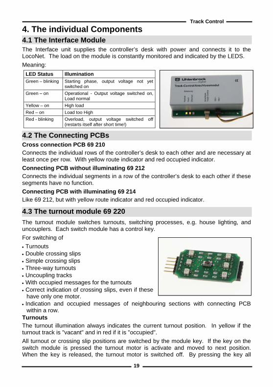
Track Control4. The individual Components 4.1 The Interface Module The Interface unit supplies the controller’s desk with power and connects it to the LocoNet. The load on the module is constantly monitored and indicated by the LEDS. Meaning:
LED Status Illumination Green – blinking Starting phase, output voltage not yet
switched on Green – on Operational - Output voltage switched on,
Load normal Yellow – on High load Red – on Load too High Red - blinking Overload, output voltage switched off
(restarts itself after short time!)
4.2 The Connecting PCBs Cross connection PCB 69 210 Connects the individual rows of the controller’s desk to each other and are necessary at least once per row. With yellow route indicator and red occupied indicator. Connecting PCB without illuminating 69 212 Connects the individual segments in a row of the controller’s desk to each other if these segments have no function. Connecting PCB with illuminating 69 214 Like 69 212, but with yellow route indicator and red occupied indicator.
4.3 The turnout module 69 220
The turnout module switches turnouts, switching processes, e.g. house lighting, and uncouplers. Each switch module has a control key. For switching of • Turnouts • Double crossing slips • Simple crossing slips • Three-way turnouts • Uncoupling tracks • With occupied messages for the turnouts • Correct indication of crossing slips, even if these
have only one motor. • Indication and occupied messages of neighbouring sections with connecting PCB
within a row. Turnouts The turnout illumination always indicates the current turnout position. In yellow if the turnout track is "vacant" and in red if it is "occupied". All turnout or crossing slip positions are switched by the module key. If the key on the switch module is pressed the turnout motor is activate and moved to next position. When the key is released, the turnout motor is switched off. By pressing the key all

20
Track Controlrepeatedly all possible turnout/crossing positions can be cycled in turn: on turnouts 2 different positions, with simple crossing slips and three-way turnouts have three positions, with double crossing slips four positions. Hint: TC Edit can set the module so that the module indicators flash while the turnout is being cycled. Flashing rate and time are fixed in the module and can not to be altered. If the turnout receives an instruction from the LocoNet and is already in the correct position the indicator does not flash. Switching Processes With each manipulation of the key the state of the attached load is changed. LED Meaning Off Function switched off On - yellow Function switched on
Uncoupler All uncouplers with a solenoid can be connected. The uncoupler beam remains up for as long as the key remains pressed or the maximum switching time for solenoids in the Intellibox times out (see chapter "Basic Settings – Accessory settings - Switch times" in the Intellibox manual).
4.4 Signal Module 69 230 The signal module is used for • Entry and Exit signals • Main, shunting and warning signals • Start / end keys • Track keys • Auxiliary keys • Indication and track occupation message in a
signal section and neighbouring sections with connecting PCBs within a row
Signal control for home and track barring signals If not differently programmed with TC-Edit the state of main and track barring signals are switched with the module key. If the key on the signal module is pressed the signal switches to the other state. For home signals e.g. from "red" to "green" and track barring signals from "yellow" to "red". The matching signal illumination always indicates the current signal state. More signal functions TC-Edit can program additional signal functions: • Switching of multi-function signals with group keys • Dynamic allocation of warning signals to home signals in a route • Module key is start and/or end key of a route • Illumination and track occupation message in the signal section as well as in the
neighbouring section with connecting PCBs in a row.
21
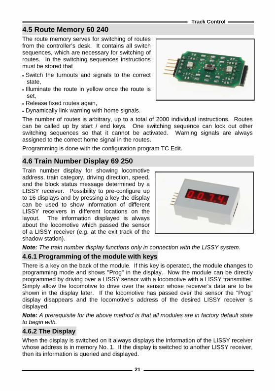
Track Control4.5 Route Memory 60 240 The route memory serves for switching of routes from the controller’s desk. It contains all switch sequences, which are necessary for switching of routes. In the switching sequences instructions must be stored that • Switch the turnouts and signals to the correct
state, • Illuminate the route in yellow once the route is
set, • Release fixed routes again, • Dynamically link warning with home signals. The number of routes is arbitrary, up to a total of 2000 individual instructions. Routes can be called up by start / end keys. One switching sequence can lock out other switching sequences so that it cannot be activated. Warning signals are always assigned to the correct home signal in the routes. Programming is done with the configuration program TC Edit.
4.6 Train Number Display 69 250 Train number display for showing locomotive address, train category, driving direction, speed, and the block status message determined by a LISSY receiver. Possibility to pre-configure up to 16 displays and by pressing a key the display can be used to show information of different LISSY receivers in different locations on the layout. The information displayed is always about the locomotive which passed the sensor of a LISSY receiver (e.g. at the exit track of the shadow station). Note: The train number display functions only in connection with the LISSY system. 4.6.1 Programming of the module with keys There is a key on the back of the module. If this key is operated, the module changes to programming mode and shows "Prog" in the display. Now the module can be directly programmed by driving over a LISSY sensor with a locomotive with a LISSY transmitter. Simply allow the locomotive to drive over the sensor whose receiver’s data are to be shown in the display later. If the locomotive has passed over the sensor the "Prog" display disappears and the locomotive’s address of the desired LISSY receiver is displayed. Note: A prerequisite for the above method is that all modules are in factory default state to begin with. 4.6.2 The Display When the display is switched on it always displays the information of the LISSY receiver whose address is in memory No. 1. If the display is switched to another LISSY receiver, then its information is queried and displayed.

22
Track Control
4.6.2.1 Display of basic functions and switching operation If the LNCV 2 of the LISSY receiver is set to modes 0-3 (basic switching functions) the address of locomotive which last passed this sensor is displayed. 4.6.2.2 Display of automatic operations If the LISSY receiver is programmed to one of the automatic functions 20 to 26 (shuttle train services, holding place, block section or station administration) the display shows the information of the locomotive occupying the track section. If the section is vacant the display changes to "Block vacant". If the display is switched to another LISSY receiver then the information of the locomotive occupying that section is displayed. "Block vacant " is displayed for vacant section (applies for LISSY receiver 68 600 starting with software-Version 1.06). 4.6.2.3 The different Displays The address range that can be monitored by a LISSY receiver is 1-9999 for locomotive addresses and 10001-16382 for wagon addresses. The different addresses are displayed as follows: Locomotive address Displays a maximum of four digits without points, e.g. locomotive address 320. Wagon address Displays four digits with points in which the first digit of the address is missing (always the 1), e.g. for the car address 10074. Display of locomotive speed Displays maximum of 3 digits with trailing point, e.g. for a speed of 50 Km/h. Display of the train category with driving direction The train category is displayed to right and the driving by a vertical bar at the left. e.g. display of the train category 2 with vertical bar on the top-left for driving direction from sensor 1 to sensor 2 and display of the train category 4 with vertical bar bottom-left for driving direction from sensor 2 to sensor 1. Display of no locomotive/block vacant The message "no locomotive" is displayed if, after switching the layout on no locomotive has passed the LISSY receiver (LNCV 2 = 20-26) block section is vacant. 4.6.2.4 Display Mode In factory default setting the display shows only the locomotive and/or wagon address. Additionally speed and/or train category with driving direction can be selected using LNCV 28.
LNCV Description Value Default 28 Display mode
0 = only locomotive address 1 = locomotive address + speed 2 = locomotive address + train category with direction 3 = locomotive address + speed + train category with direction
0-3 0

23
Track Control
If several information items are selected they are displayed in turn. The display duration of the individual items can be individually set (see next chapter). Note: Speed and driving direction can only be indicated, if the LISSY receiver is used with a double sensor (see LISSY manual, chapter "Reporting speed and direction "). 4.6.2.5 Time Display If the LNCV 28 contains a value other than 0 the display shows the selected information of a LISSY receiver in turn. How long the information is to be shown can be adjusted in LNCV 29 in 0,5 second steps. The preset value is 3 seconds (LNCV 29 = 6). Note: The settings in LNCV 28 and 29 apply to all used display memories. 4.6.3 Configuring the Screen display memory For the display of the train number display, 16 different display memories are available. Each display memory can be assigned an individual LISSY receiver address which is to be displayed. For the configuration of the display memory the following LNCVs serves:
LNCV Display Memory Key LISSY receiver Address Default 11 1 1 Receiver address for Display Memory 1 1 12 2 4 Receiver address for Display Memory 2 0 13 3 2 Receiver address for Display Memory 3 0 14 4 5 Receiver address for Display Memory 4 0 15 5 3 Receiver address for Display Memory 5 0 16 6 6 Receiver address for Display Memory 6 0 17 7 C Receiver address for Display Memory 7 0 18 8 + Receiver address for Display Memory 8 0 19 9 7 Receiver address for Display Memory 9 0 20 10 Receiver address for Display Memory 10 0 21 11 8 Receiver address for Display Memory 11 0 22 12 0 Receiver address for Display Memory 12 0 23 13 9 Receiver address for Display Memory 13 0 24 14 Receiver address for Display Memory 14 0 25 15 Receiver address for Display Memory 15 0 26 16 Receiver address for Display Memory 16 0
The 16 different display memories can be selected by the number keys of the Intellibox as shown in the picture. Simple turnout commands switches between the individual displays. In addition, in keyboard mode, the Intellibox top-left pair of keys is the address assigned into the LNCV 27 of the module which was registered as "start address for switching the display". In factory setting the train number display is not programmed to "change over", i.e. the LNCV 27 has the value "0". The key assignment of the Intellibox can be changed as described in the Intellibox manual chapter "Keyboard Mode - Changing Key Assignment". Note: Turnout addresses must not be set in the address range which the display uses for the display memory! Please note that altogether 8 addresses are used for the eight pairs of keys on the keyboard. In factory setting the change over is deactivated.

24
Track Control
4.7 Track-control speed controller with DirectDrive function 4.7.1 Description The speed controller switches up to 16 special functions (DCC) and the light function. It
has a large rotary regulator for speed control. Pressing on the rotary regulator activates an emergency stop and the driving direction is changed. Besides the normal driving functions it has another special feature: the DirectDrive function with which control of a locomotive can be taken over without input of the address. 4.7.2 Connection The speed controller is as large as three desk segments and can be easily integrated into the desk. It connects the PCBs within a column and three rows. No other cross connections are needed in the row where the speed controller is located.
4.7.3 Control Elements 4.7.3.1 Rotary Knob The speed controller has two different operating modes. AC speed controller mode: the continuous rotary controller can change the speed of the locomotive. If the rotary button is pressed the current locomotive is stopped by emergency stop and the driving direction is changed (factory setting). DC speed controller mode: the continuous rotary controller changes the speed and the driving direction of the locomotive can be changed as with a speed controller in central position. If the rotary regulator is pressed then the current locomotive is stopped by emergency stop. There is a detailed description in the Intellibox manual chapter "The Control Panel - The speed knob (throttle)". 4.7.3.2 Number keys to input addresses Allocation of the keys for the number input corresponds to the numbers that are marked for the function keys: 1 for the [f1]-key to 0 for the [f0]-key. 4.7.3.3 Function keys [f1] to [f8] If the speed controller has a locomotive under control keys [f1] to [f8] it can switch the locomotive’s special functions f1 to f8 and the [f0]-key for the light function. The associated LEDs are off when the function is switched off and are yellow when the function is switched on. 4.7.3.4 [f9...]-key Special functions f9 to f16 (DCC) can be switched by pressing the [f1] to [f8] keys together with the [lok#]-key. The left LED above the [f9...]-key is yellow in this mode. If the right LED above [f9...]-key flashes blue a LISSY receiver has sent a shunting command for the current locomotive. By manipulation the [f9...]-key can take over the shunting mode. The shunting mode is also terminated when the [f9...]-key is pressed (see to chapter 4.7.7 "Shunting mode").

25
Track Control4.7.3.5 The [lok#]-Key Starts the input of a locomotive address and terminates it again. 4.7.3.6 Meaning of LEDs In running mode
LED above [ f0 ] to [ f8 ] Meaning Off Light or Special function off On - yellow Light or Special function on
LEDs above [f9...] Meaning Left LED glows yellow The [f9...]-key was pressed.
If the controller has control of a locomotive under control the [f1] to [f8] keys can switch the locomotive special functions f9 ti f16 (DCC)
Right LED blinks blue For 5 seconds
A LISSY receiver has sent a shunting command to the current locomotive. Take over the shunting mode with the [f9...]-key.
Right LED glows blue The controller is in shunting mode. Exit shunting mode with the [f9...]-key.
LED above [lok#] Meaning Off No locomotive selected by the controller. Blinks yellow A locomotive has passed an associated LISSY receiver.
This can now be taken over with the [lok#]-key. Blinks green The [lok#]-key was pressed. Now you can:
• Enter a locomotive address with number keys and take over with the [lok#]-key or
• Press [f0] - [f0] - [lok#] to take over the last locomotive passed the associated LISSY receiver or
• Press [f0] - [lok#] to take over a locomotive in the dispatch memory. Glows green The speed controller has a locomotive under control. Glows red At the center a short-circuit or the press of the stop key on the control
center has switched the track power off. Track power is switched back on by the control center by pressing the speed controller’s [ lok#]-key.
In the shunting mode LED above [ f1 ] to [ f4 ] Meaning Off Solenoid switched to red - round On - yellow Solenoid switched to green - straight
4.7.4 Locomotive selection by address input Allocation of the keys for the number input corresponds to the numbers that are marked for the function keys: 1 for the [f1]-key to 0 for the [f0] key. • Press the [lok#]-key.
The LED above the [lok#]-key flashes green. • Enter the locomotive address with the keys [f0] to [f9...]. • Confirm With the [lok#]-key.
The LED above [lok#]-key glows green. The locomotive can be controlled with the speed controller.

26
Track Control4.7.5 Locomotive selection by DirectDrive The DirectDrive feature allows a locomotive that passes a LISSY receiver to be taken over by a push of a key on the speed controller without knowing the locomotive address. 4.7.5.1 Locomotive selection from a LISSY receiver A typical example is a LISSY receiver at the exit track of an automatically controlled shadow station. No matter which locomotive is exiting the station, with DirectDrive you can take over its control without having to know the address. Selecting a LISSY receiver First a LISSY receiver must be assigned to the speed controller. The speed controller must not have a locomotive address assigned to it. The LED above [lok#]-key must be off. If necessary the current locomotive address must be deleted by pressing the [lok#]-key twice. • Then keep [lok#]-key pressed for 10 seconds.
All LEDS above the function keys [f1] to [f8] flash. • Drive over the selected LISSY receiver with a locomotive.
Now the LISSY receiver is assigned to the speed controller. • If a locomotive passes the assigned LISSY receiver the LED above [lok#]-key flashes
yellow. Note: The LISSY receiver must have "data output to LocoNet" activated by setting bit 0 in LNCV 15 to 1! Taking over a Locomotive The speed controller [lok#]-key can now be used to take control of the locomotive which passes the assigned LISSY receiver. The LED above [lok#]-key glows green. Cancelling a Locomotive If you want to take control the offered locomotive later then you can cancel the locomotive just offered by the assigned LISSY receiver. • Delete the request by pressing [f9...]-key.
The LED above [lok#]-key stops flashing yellow. The address is not taken over. The old locomotive remains on the speed controller. The LED above [lok#]-key glows green again
Recall a Locomotive A cancelled locomotive can be taken over by the speed controller later. • Press the [lok#]-key.
The LED above [lok#]-key flashes green. • Press the [f0]-key twice. • Confirm with [lok#]-key. Note: The speed controller always offers the last locomotive to pass the assigned LISSY receiver. 4.7.5.2 Locomotive selection via a Track-control signal or track key module A locomotive is in a track section which is monitored by a LISSY receiver e.g. a station track or a block section. The address of the LISSY receiver was assigned to the signal or track key module for this section. As soon as the LISSY receiver detects a

27
Track Controllocomotive and feeds its address to the LocoNet the locomotive can be taken over by DirectDrive on the speed controller. • Press and hold the Key of the signal or track key module. • Press and release [lok#]-key. • Release the Key at the signal or track key module.
The locomotive can be controlled with the speed controller.
4.7.6 Locomotive selection by Dispatch mode A locomotive address can be put down in the dispatch memory for every speed controller attached to the LocoNet and can the taken over by another speed controller. 4.7.6.1 Taking over a Locomotive address from the Dispatch memory • Press the [lok#]-key.
The LED above [lok#]-key flashes green. • Press [f0]-key. • Confirm with [lok#]-key.
The LED above [lok#]-key glows green. The locomotive can be controlled with the speed controller.
4.7.6.2 Hand over a Locomotive address to the Dispatch memory • Press the [lok#]-key twice. • The last controlled locomotive address is now in the LocoNet’s dispatch memory. The speed control no longer has a locomotive selected. The LED above [lok#]-key is out. 4.7.7 Shunting mode In close-to-reality running during shunting only the next turnout of the route is suitably switched. For selected locomotives a shunting instruction is sent by the LISSY receiver. This command consists of the locomotive address and solenoid address for switching the next turnout. If the speed controller has the locomotive with the current address under control and it drives over the appropriate LISSY receiver, the speed controller offers the shunting mode. The right, blue LED above [f9...]-key flashes for approx. 5 seconds. If the [f9...]-key is pressed the speed controller switches into the shunting mode and the blue LED lights up. With [f1] to [f4] keys the solenoids with the following addresses can be switched: f1: received address from the shunting command f2: received address + 1 f3: received address + 2 f4: received address + 3 The LEDs above the keys indicate the status of the solenoids: LED Meaning Off Solenoid status red, round On - yellow Solenoid status green, straight
Pressing [f9...]-key switches the speed controller back to driving mode. 4.7.8 Turn track power back on The control center switches track power off for a short circuit or pressing of the stop key. The LED above [lok#]-key glows red. By pressing [lok#]-key on the speed controller is the control center turns the track power back on.
28
Track Control
4.7.9 Speed controller mode change The speed controller may not have a locomotive address assigned to it. The LED above [lok#]-key must be off. If necessary the current locomotive address be deleted by pressing the [lok#]-key to twice. • Then keep [lok#]-key pressed for 10 seconds.
All LEDs above the function keys [f1] to [f8] flash. • Press the rotary knob once.
The LEDs extinguish the speed controller mode is toggled from the AC to DC mode or vise-versa.
5. Track-control in the analog layouts Track-control can be used with full capacity in DC and AC model railway facilities.
5.1 Requirements • All turnout lamps and signals that are to be switched from the control desk are
connected via LocoNet Switch modules. They receive their switching commands from the Track-control module.
• If track sections are to illuminate in red for occupied indication, then track occupation modules and LocoNet feedback modules, which connect via LocoNet power feed modules (Part No. 63 100) are needed.
• The Track-control module must be changed to analog operation. • To program LocoNet Switch modules and LocoNet feedback modules you need the
LocoNet interface (Part No. 63 110) together with the "LocoNet Tool" program which is supplied with the interface. The program runs on all PCs with operating systems starting from Windows 98 SE.
Note: For application references for the LocoNet modules and the LocoNet Tool please use the appropriate operating manual.
5.2 Connection of the LocoNet interface Connect the LocoNet interface to a PC COM port with a modem cable. Connect it to the Track-control module with LocoNet cable. Install the "LocoNet Tool" software and the "TC-Edit" program.
5.3 Track-control module to analog enterprise change over The Track-control module is changed to analog operation with the TC-Edit program. It then takes over the function of a LocoNet center for the LocoNet modules used here.

29
Track Control
5.4 Connection of the Switch Module Each LocoNet Switch module (Part No. 63 410) has 20 output terminals for 20 different loads. Each of the 20 output functionality can be configured individually. • The Switch modules receive their own 16V transformer supply power for the turnouts
and signal. • Each Switch module receives its own module address. • All loads like turnouts, lamps and signals that are to be switched from the controller
desk are connected via LocoNet Switch modules. • The Track-control module is connected to any Switch module by LocoNet cable. This
is connected by LocoNet cables with all other Switch modules. The LocoNet cables are supplied with each of the modules.
• The LocoNet Tool is used to finally assign the respective turnout and signal addresses to the outputs of the LocoNet Switch modules.
Note: For the exact procedure please read the appropriate operating instructions.
5.5 Red indication of occupied track sections If track sections are to show a red illumination for the occupied indication then the following components are needed: • Track occupation alarm unit Part No. 43 500 (for two track sections) • Feedback module Part No. 63 350 (for 8 track occupation alarm, hence 16 sections) • LocoNet Power feed Part No. 63 100 (to supply current to the feedback modules) The input of the LocoNet Power feed is attached to the free LocoNet socket of a Switch module. The LocoNet output of the Power feed unit then connects feedback modules with the enclosed Loco Net cables. The output of the track occupation alarm units are then connected with the contacts of the feedback modules. Note: To the exact procedure please read the appropriate operating instructions.
5.6 Saving of the operating States If the current state of turnouts, signals and feedback modules are to be automatically saved when switching the layout off then the module can be programmed accordingly with TC-Edit. When the layout is next switched on these states are available again.

30
Track Control
Appendix What is LISSY? With the (Locomotive individual Control System) LISSY you can easily achieve controls on your digital layout which were possible on analog layouts for a long time. LISSY meets the needs of Model railroaders who would like to provide their digital system with simple automatic control functions like block traffic and shuttle trains without the need of a computer. LISSY works without track isolation. LISSY achieves the following on a digital layout: Train recognition - shuttle train control – locomotive-dependent shadow station control - digital block control - speed measurement - starting and brake inertia at signals - automatic control of special functions. Product overview
Part No. Description Size in mm 69 000 Track-Control Basis Set - 69 010 Track-Control expansion Set - 69 090 1 Set adhesive Symbol stickers (100 pieces) - 69 100 6 Plastic segment with diffuser, 8 connector plugs 40 x 25 x 12 69 210 2 Cross-connector PCB 37 x 22 x 7 69 212 4 connection PCBs without illumination 37 x 22 x 7 69 214 2 connection PCBs with illumination 37 x 22 x 7 69 220 1 Turnout PCB, 1 key cap grey 37 x 22 x 7 69 230 1 Signal PCB, 1 key cap grey 37 x 22 x 7 69 240 1 Route Memory PCB 37 x 22 x 7 69 250 1 Train number display, complete with plastic segment 40 x 25 x 12 69 300 1 Speed controller 40 x 75 x 28 20 040 Transformer 16 V -
Contents of the two sets Basic Set Extension Set Contents
30 30 Plastic segments with diffusers 45 45 Connection plugs 32 32 Key caps in various colours 3 4 Turnout PCB 3 4 Signal PCB 4 2 Cross connection PCB 2 4 Connection PCB without illumination 1 1 Set of adhesive Symbol stickers (100 Pieces) 1 - Connection Module 1 - Connection Cable 50 cm 1 - LocoNet-Cable 60 cm 1 - CD with “TC-Edit“ program 1 - Manual

31
Track Control Hotline
Our Hotline is available for you Monday to Friday 14:00-16:00
Wednesdays 16:00-18:00 02045 - 8583 - 27

Autors: Dr.-Ing. T. Vaupel, D. Richter, M. BergerTranslation: Wolfram Steinke
© Copyright Uhlenbrock Elektronik GmbH, Bottrop
1st Edition August 2007 All rights reserved
Reproduction in full or in part only with permission
Order Number 60 800