manual smartbox 29-09-2016 - cumulocity · pdf file- value/ operations ... type the imei of...
TRANSCRIPT

PSsystec SMARTbox Agent User‘s Guide
Application Manual
PSsystec GmbH • Heinbergstr. 27 86 356 Neusäß • www.pssystec-gmbh.de
Cloud Fieldbus

PSsystec SMARTbox Agent User‘s Guide
PSsystec SMARTbox Agent User‘s Guide
Overview
Smartbox Modbus, based on the Telit Chipset HE910 is a ready to use solution for connecting Sensors and in parallel Modbus devices to the Cumulocity. It provides a Master Slave Communication on RS485 for connecting up to 20 devices. Easy confi gure the confi guration of building automation fi elddevices like pumps, chillers, E-meters, Airhandling units in Cumulocity – the Smartbox Modbus will take care of it!
TemperaturNTC10K | -50°C – 105°CPT100| -200°C – 600°CPT1000| -200°C – 600°CCU50 | -50°C – 105°CCU100| -50°C – 105°C
StromST50 | 0...50AST100 | 0...100AST200| 0...200A
Drucksensoren4...20mARatiometrisch 0...5V
SchaltkontakteTürkontakteFlusswaechter
Feuchte0...10V4...20mA
Fuellstandssensor
1...10 Sensoren(Typ freiwählbar)
SMARTBox
Robustes Aluminiumgehäuse100mm x 70mm
1..10 Sensoren(frei wählbar)Phoenix Klemmfeld
2 Draht pro Sensor
Sensorauswahl auf der CloudPlug & Play Solution
Magnethalterung od.
Montage
Hutschienenclip
Up to 20 Devices, max. 1000 datapointsModbus RTU RS485 on Board
Alarming, Auslesen, Steuern, Monitoren aller modbusfähiger Geräte
Developed for Cloud Fieldbus- Flexible Device database- Alarming- Events- Measurments- Value/ Operations- SetUp Modbus MasterCommunication- Remote restart
Format 2FFSIM Card
Betriebsspannung 12-24V
By automatically picking up the coils and registers and sending alarms, measurements and status back to Cumulocity.
Pssystec GmbH is specialized in building automation. With SMARTbox Modbus we developed a slim Line M2M device, fully integrated in the HVAC market.

PSsystec SMARTbox Agent User‘s Guide
The Smartbox comes up with diff erent hardware confi gurations. If you don’t fi nd your confi guration, get in contact with us. We have a fl exible IO system which allows to change the IO confi guration to your needs.
Wire your Sensors and Modbus RTU RS485 NetworkThe Hardware interface is as follows:
12V-24V DC
Spannung vorhanden
Sensormessung bereit (flackernd)
Spannung Funkeinheit
GSM Netz
Mobilfunk
Antenne
Modbus RTU RS485
Smartbox HW Typ A HW Typ B HW Typ C HW Typ D HW Typ E HW Typ F
Max. No Sensors 10 4 10 10 10 10
Sensors
NTC 10 - 10 - - -
ON/OFF (voltage free) 10 - 10 - 8 -
PT100 - 4 10 - - -
PT1000 - 4 10 - - -
Cu50 - 4 - - - -
Cu100 - 4 - - - -
4..20mA - - - 10 - -
0..10V - - 6 - - 10
Fieldbus 0..5V 10 - 6 - - -
Out Relais Output - - 1 - - -
Fieldbus Modbus RS485 Yes Yes Yes Yes Yes Yes

PSsystec SMARTbox Agent User‘s Guide
Connecting the terminal
After clicking the „accept“ button, navigate to „All devices“, the terminal should appear after ≈ 30 seconds after registration.
After setting APN, register your SMARTbox Modbus to Cumulocity. „Connecting devices“: Type the IMEI of the terminal in the registration tab of Cloud Fieldbus and press register. The IMEI is printed on the back side of the terminal as shown in the screenshot below.
Confi gure the terminal
By default the terminal supports Cloud Fieldbus from cumulocity. To do so, you need to:• Subscribe your account to the Cloud Fieldbus app by contacting [email protected] or
[email protected]• To confi gure your APN put your SIM CARD to the Smartbox. After this, power On the Smartbox Modbus
, wait > 10 seconds – and send an SMS to the phone number, given by the provider from your SIM CARD.
Change APN Send SMS with APN, > 10s after Power onGPRS=public4.m2minternet.com
From this point, the Smartbox stores your set APN.

PSsystec SMARTbox Agent User‘s Guide
After this step:
Configure the sensors
Depending on the Typ (A-F) you have to do following steps:
1. Switch to the tab “Device database” in fieldbus3. And put the data to the device:Add the device Smartbox A:
PSsystec SMARTbox Agent User‘s Guide
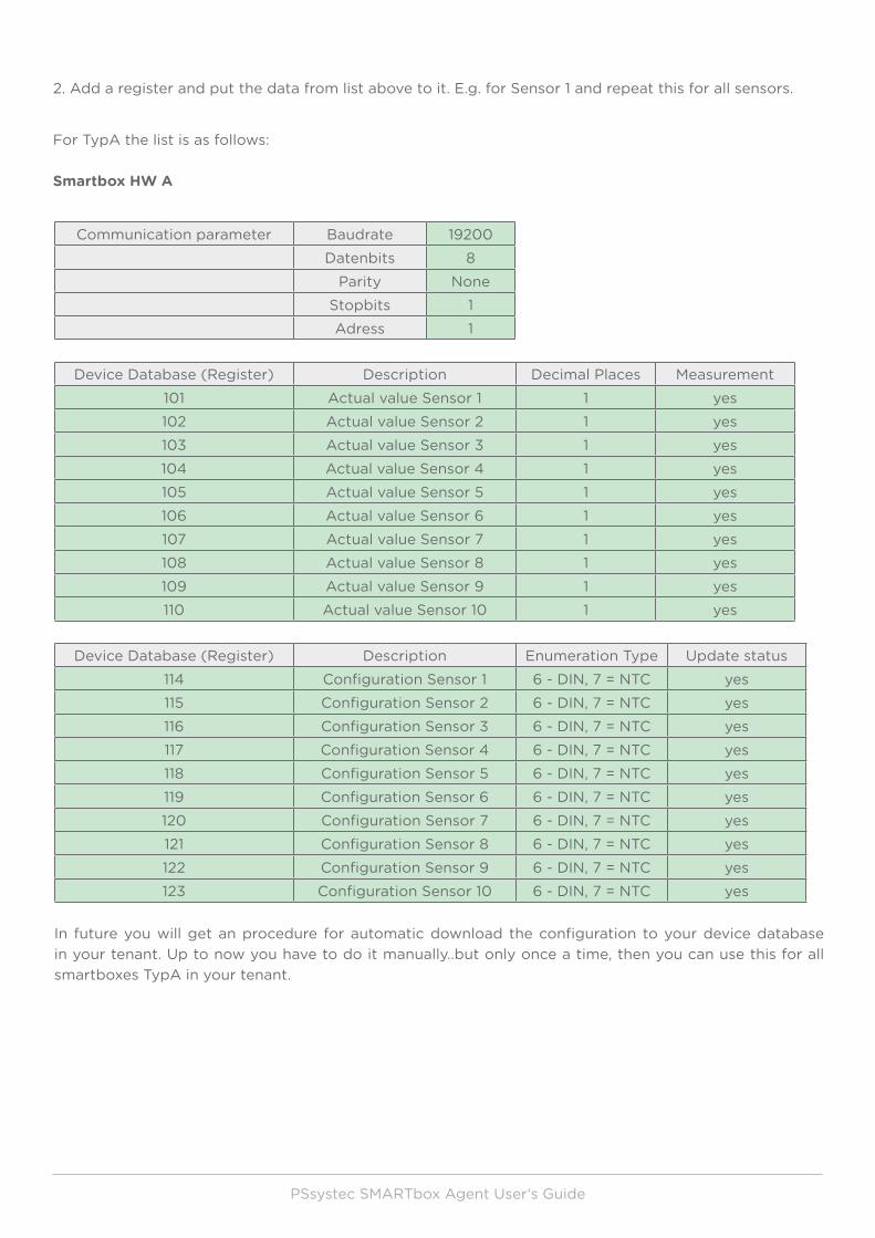
Communication parameter Baudrate 19200Datenbits 8
Parity NoneStopbits 1Adress 1
Device Database (Register) Description Decimal Places Measurement101 Actual value Sensor 1 1 yes102 Actual value Sensor 2 1 yes103 Actual value Sensor 3 1 yes104 Actual value Sensor 4 1 yes105 Actual value Sensor 5 1 yes106 Actual value Sensor 6 1 yes107 Actual value Sensor 7 1 yes108 Actual value Sensor 8 1 yes109 Actual value Sensor 9 1 yes110 Actual value Sensor 10 1 yes
Device Database (Register) Description Enumeration Type Update status114 Configuration Sensor 1 6 - DIN, 7 = NTC yes115 Configuration Sensor 2 6 - DIN, 7 = NTC yes116 Configuration Sensor 3 6 - DIN, 7 = NTC yes117 Configuration Sensor 4 6 - DIN, 7 = NTC yes118 Configuration Sensor 5 6 - DIN, 7 = NTC yes119 Configuration Sensor 6 6 - DIN, 7 = NTC yes120 Configuration Sensor 7 6 - DIN, 7 = NTC yes121 Configuration Sensor 8 6 - DIN, 7 = NTC yes122 Configuration Sensor 9 6 - DIN, 7 = NTC yes123 Configuration Sensor 10 6 - DIN, 7 = NTC yes
In future you will get an procedure for automatic download the configuration to your device database in your tenant. Up to now you have to do it manually..but only once a time, then you can use this for all smartboxes TypA in your tenant.
2. Add a register and put the data from list above to it. E.g. for Sensor 1 and repeat this for all sensors.
For TypA the list is as follows:
Smartbox HW A

PSsystec SMARTbox Agent User‘s Guide
Example for setup Sensor1 – Measurment data
Address
Decimal Places 1
Signed
Set Send Measurement
Define the name of the measurement
Type the unit e.g. °C
Type a Name for sensor1 (any name)Type a Name for sensor1 (any name)
Address
Decimal Places 0
UnSigned
Define Read/Write for configuration
Defining the enum Values
Now you made the Setup for the Sensors in Smartbox TypA. In the next chapter you setup the Modbus network. You need to add this device to the Smartbox you are using.

PSsystec SMARTbox Agent User‘s Guide
Confi gure the Modbus network (optional)
Lets make an example: Assume you have a data center application: A chiller provides constant cold water of 7°C at the outlet. For each Serverrack line, a precision airconditioner is installed which maintain the racktemperature to 20°C by blowing cool Air through the fl oor grid to the racks. The warm air at the outlet of each rack will be again cooled down by a heat exchanger, installed in the air conditioning units, feeded from cool water coming from the chiller. Your company servicing the cooling system for your customer.
Modbus RTU RS48519200 Baud, 8/N/1
Slave Adress 1
Slave Adress 5 Slave Adress 6
Chiller
Slave Adress 2
Energy Meter

PSsystec SMARTbox Agent User‘s Guide
To connect this datacenter application to Cumulocity follow these steps. Be aware, that due to the sensors following is fi xed:Adress1 is reserved for the sensorsCommunication frame: 19200/8N1
1. The Smartbox, acts as a Modbus Master. Connect all slaves together in one line and put diff erent Slave
addresses in the fi elddevices, as well as a common Baudrate and Communication frame (e.g. 8/N/1).
Normally all fi elddevices provides such setting at a local display.
2. For each diff erent Fielddevice (Chiller, AirConditioning units, Energy meter) create the Device database
in Cloud Fieldbus in Cumulocity (see the Appendix “Create” Device Database).
3. SetUp in Modbus confi guration Tab
A. Set Field Communication Parameter
B. Set Communication parameter between Smartbox and Server. Note Events, Alarms, Values
(See device database) are transmitted to server if the read out value from Modbus is changed.
So only the transmitrate for measurements is defi ned.
C. BuildUp the network by adding slave devices defi ned in the device database. In Cumulocity,
each Fielddevice come up with a single childdevice. So in this cases we would have 3
childdevices. After adding the slave devices, the terminal will discover all childdevices and its
Modbus items and begin feeding the platform with measurements, alarms, events, values. Note:
Without a setup network, the terminal will not send any data.

PSsystec SMARTbox Agent User‘s Guide
The default name of the terminal is the IMEI. Click on the terminal to view the detailed information. You can change the terminal‘s name on the „Info“ tab, which also displays basic information such as serial number of the router and SIM card data. After changing the name, remember to click „save changes“ button at the bottom of the „Info“ page. All data coming from the fielddevices are available under the section childdevices.
Manage the Application
1. General: Managing the sensors or Modbus itmes form any field devices is at least the same. Only in case of sensors you will not have events or alarms, you will need only the measurement tab in the child device to browse the values and fieldbus- widget to set the type of sensor according to the device model from Type A for example.
Manage: In order to monitor the Measurements, events, alarms from the fielddevices, go to the child device tab. Inside each childdevice tab all relevant data are available according to the specific device and the set configuration in the device database.
To see and manage the values which are defined in Device database as ReadStatus for Read values or Update Status for Read/Write Values add a tab including the fieldbus widget (which comes up with the fieldbus3 application). Hear you can set and read out and write these defined values.

PSsystec SMARTbox Agent User‘s Guide
For the sensors connected directly to the Smartbox, you will need: a) The measurement tab for browsing the sensor values b) The fieldbus widget to set the configuration o0f the sensors
2. Sending Alarm, Events, Measurements, Values: The Send cycle is as follows:
Send cycle Values (Readstatus) On Change Add Fieldbus-widgetValues (Updatestatus) On Change Add Fieldbus-widgetAlarms On Change Found in Alarmtab ChildeviceEvents On Change Found in Events ChildeviceMeasurements Defined in Modbus tab Found in Measurments
ChildeviceSignal strength Is sent every 10 Min as an
measumentFound in Measurments
3. Monitor the success of operations: All operations send from server to the samrtbox can be monitored if they are successful processed. Operations are e.g. Changing the transmit rate, changing Modbus communication frame, adding new slave devices, remote restart, changing values on the Modbus (Updatestatus)

PSsystec SMARTbox Agent User‘s Guide
4. Restart the terminal: The terminal can be restarted either by power On/off or Remote Restart by Cumulocity Device Control, on terminal level
5. Location: The terminal features cell Location and is available in Location tab on terminal level.
6. Signal strength: The signal strength of the terminal is sent each 10minutes and is displayed as a measurement on terminal level.
7. Indication and Software Version: Go to Indication and Software tab to identfy the terminals IMEI, Version and FW installed.

PSsystec SMARTbox Agent User‘s Guide
8. Real time Clock: The terminal has an Real Time clock installed. Each time a measurement, event or alarm is sent to Cumulocity, the time is retrieved from the internal real time clock and gets the GMT time from a NIST server. This means, you don’t need to use a SIM Card with the NITZ feature.
9. Buffering data: In case of bad connection, measurements, events, alarms are permanently stored in an internal buffer. About 24h can be stored in case of bad communication. Getting online again the terminal sends the data to Cumulocity.
Appendix: “ Create Device database”
1. Select the tab Device database and add device type
General: The SmartboxModbus supports following Function Codes:
FC1 Read Coils (Address Cumulocity == AddressDevice +1) FC2 Read Input Status (Address Cumulocity == AddressDevice +10001) FC3 Read Register (Address Cumulocity == AddressDevice +1) FC4 Read Input Register (Address Cumulocity == AddressDevice +10001) FC5 Write Coils (Address Cumulocity == AddressDevice +1) FC6 Write Register (Address Cumulocity == AddressDevice +1)

PSsystec SMARTbox Agent User‘s Guide
Taking the Modbus Datapoint list from your device you want to connect to the smartbox, you can now defi ne all registers and coils in the Device database by adding register or adding coils. Note: The limitation is 100 datapoints if you have 10 slave devices or 1000 datapoints if you have only 1 device you want to connect.
2. Add Registers
Name of datapoint displayed in CC Datapoint Tab (used in Fieldbus Widget)
Address of Register in the Slave(+1 or +10001, according to FC3 or FC4)
Scaling of Value:Value in CC == Value * Multiplier / Divisor * 10-DecimalPlaces
Unit displayed in CC Datapoint Tab (used in Fieldbus Widget)
Needed to limit the user input
values (Fieldbus Widget)Signed Value = the value has an + or -
Needed, if Value has Enum Values like On, Off, Defrost (used in Fieldbus Widget)
Definition of enum Values (used in Fieldbus Widget)
Readout the Value without Timestamp, (Display in FieldbusWidget)
Read/Write Value without Timestamp, (Display in FieldbusWidget)
Readout the Value withTimestamp, Display Graph in Measurements of Childdevice (ModbusSlave)
Alarm with Timestamp, (Display in Alarms of Childdevice)0 = no Alarm, 1 = AlarmNote: This Alarm can only be publised from the device to CC. it must be acknoledged in CC. The device send no „clear“ to the Alarm in CC, even if the alarm is not present anymore on the device
Event with Timestamp, (Display the Measured Value in Events of Childdevice)
DisplayCategroy, Displayed in FieldbusWidget
Defines which bits of the 16bit register assigned to this datapointStartbit = Starting BitNumber of Bits = Number of bits used of the 16Bit Register
LSBMSB
Bit0Bit15
StartBit 0
Defining Measurements:Series: Name of Measured Value e.g. same as under „Name“ (Display in Tab Measurements)Type: Possibility to groupe measurments. But you can take any name e.g. same as „Name“
Defining Alarms:Alarm Type: Possibility to groupe, But you can take any name e.g. same as „Name“Alarm Text: Displayed text in Alarm tab folderAlarm Severity: Diplayed Severity in Alarm tab folder
Defining Events:Event Type: Possibility to groupe, But you can take any name e.g. same as „Name“Event Text: Displayed text in Event tab folder

PSsystec SMARTbox Agent User‘s Guide
3. Add Coil
Name of datapoint displayed in CC Datapoint Tab (used in Fieldbus Widget)
DisplayCategroy, Displayed in FieldbusWidget
Address of Coil in the Slave(+1 or +10001, according to FC1 or FC2)
Readout the Value without Timestamp, (Display in FieldbusWidget)
Event with Timestamp, (Display the Measured Value in Events of Childdevice)
Read/Write Value without Timestamp, (Display in FieldbusWidget)
Alarm with Timestamp, (Display in Alarms of Childdevice)0 = no Alarm, 1 = AlarmNote: This Alarm can only be publised from the device to CC. it must be acknoledged in CC. The device send no „clear“ to the Alarm in CC, even if the alarm is not present anymore on the device
Definition of enum Values (used in Fieldbus Widget)
Defining Alarms:Alarm Type: Possibility to groupe, But you can take any name e.g. same as „Name“Alarm Text: Displayed text in Alarm tab folderAlarm Severity: Diplayed Severity in Alarm tab folder
Defining Events:Event Type: Possibility to groupe, But you can take any name e.g. same as „Name“Event Text: Displayed text in Event tab folder

PSsystec SMARTbox Agent User‘s Guide
PSsystec GmbH • Heinbergstr. 27 86 356 Neusäß • www.pssystec-gmbh.de