manual pod-precision omnidirectional dipole · optimize this new site-vswr measurement procedure in...
TRANSCRIPT

MANUALPOD - Precision Omnidirectional Dipole
Antenna POD 16
Antenna POD 618
Antenna Stand for Site VSWR Measurements


E M C & O P T I C S
MANUAL POD – Precision Omnidirectional Dipole
Antenna POD 16 Antenna POD 618 Site VSWR Positioner SPM1 (manual) Site VSWR Positioner SPA1 (automatic)
14.02.2011 Version 3.1

| POD MANUAL SEIBERSDORF LABORATORIES 2
Notice
Seibersdorf Labor GmbH reserves the right to make changes to any product described herein in order to improve function, design or for any other reason. Nothing contained herein shall constitute Seibersdorf Labor GmbH assuming any liability whatsoever arising out of the application or use of any product or circuit described herein. All graphs show typical data and not the measurement values of the individual product delivered with this manual. Seibersdorf Labor GmbH does not convey any license under its patent rights or the rights of others. © Copyright 2011 by Seibersdorf Labor GmbH. All Rights Reserved. No part of this document may be copied by any means without written permission from Seibersdorf Labor GmbH Contact Seibersdorf Labor GmbH EMC & Optics – RF-Engineering T +43(0) 50550-2882 | F +43(0) 50550-2881 [email protected] www.seibersdorf-laboratories.at/rf VAT no.: ATU64767504, Company no. 319187v, DVR no. 4000728 Bank account: Erste Bank, sort code 20111, account no. 291-140-380-00

SEIBERSDORF LABORATORIES POD MANUAL | 3
Table of Contents
1. INTRODUCTION ................................................................................................................................ 5 2. DESCRIPTION OF THE POD ANTENNA & POSITIONER ............................................................... 6 2.1. POD Antenna ..................................................................................................................................... 6 2.2. Site VSWR Positioner ........................................................................................................................ 8 3. CONTENT OF SETS .......................................................................................................................... 9 3.1. POD Antenna Set ............................................................................................................................... 9 3.2. Components Specific to SPA1 ......................................................................................................... 10 3.3. Components Specific to SPM1 ........................................................................................................ 10 3.4. Components for SPM1 and SPA1 .................................................................................................... 11 3.5. Site VSWR Set with SPM1 ............................................................................................................... 11 3.6. Site VSWR Set with SPA1 ............................................................................................................... 12 4. TECHNICAL SPECIFICATIONS ...................................................................................................... 13 4.1. Technical Specifications of POD Antennas ..................................................................................... 13 4.2. Radiation Pattern .............................................................................................................................. 16 4.2.1. Radiation Pattern POD 16 ................................................................................................................ 17 4.2.2. Radiation Pattern POD 618 .............................................................................................................. 19 4.3. Technical Specifications of Site VSWR Positioner .......................................................................... 24 5. INSTALLATION ................................................................................................................................ 26 5.1. Assembly of SPM1 - Manual Site VSWR Positioner ........................................................................ 26 5.2. Assembly of SPA1 – Automatic Site VSWR Positioner ................................................................... 29 5.3. Polarization Change ......................................................................................................................... 33 5.4. Change of Height ............................................................................................................................. 33 5.5. SPA1 Maintainance .......................................................................................................................... 34 5.6. Packing SPA1 in Flight Case ........................................................................................................... 34 6. SOFTWARE ..................................................................................................................................... 35 6.1. SPA Mover ....................................................................................................................................... 35 7. OPERATION .................................................................................................................................... 37 7.1. Site VSWR-Measurement ................................................................................................................ 37 7.2. Field Strength Measurements .......................................................................................................... 39 7.3. Add3D Field Strength Measurements Using sPOD Antennas ......................................................... 39 8. LITERATURE AND INFORMATION ................................................................................................ 42 9. FIGURES ......................................................................................................................................... 43 10. TABLES ............................................................................................................................................ 44 ANNEX I. WARRANTY .............................................................................................................................. 45 ANNEX II. SAMPLE CERTIFICATE OF ANTENNA CALIBRATION .......................................................... 46

| POD MANUAL SEIBERSDORF LABORATORIES 4

SEIBERSDORF LABORATORIES POD MANUAL | 5
1. INTRODUCTION The Precision Omnidirectional Dipole (POD) was developed by Seibersdorf Laboratories (former ARC) due to industry demand for an omnidirectional broadband antenna. It’s covering the frequency range 1-18 GHz with two antennas (1-6 GHz, 6-18 GHz). Design goal was a superior radiation pattern performance exceeding the standard requirements for Site VSWR measurements [1] by far. Thus has leaded to a construction which is patented by Seibersdorf Laboratories. The POD Antenna can be used for any kind of RF test where an omnidirectional broadband characteristic is required.
This manual describes in detail the application of the POD Antenna for Site VSWR measurement using the Site VSWR Positioner SPA1 and SPM1 (former POD Antenna Stand). For isotropic field strength measurements with the Field Nose system shortened versions of the antennas are available (sPOD series). Technical specification of the antennas and radiation patterns are presented.

| POD MANUAL SEIBERSDORF LABORATORIES 6
2. DESCRIPTION OF THE POD ANTENNA & POSITIONER 2.1. POD Antenna The POD Antennas cover the frequency range 1 GHz up to 18 GHz with two models:
POD 16 for the range 1 GHz to 6 GHz and POD 618 for the range 6 GHz to 18 GHz.
Covering the whole frequency range with one antenna would lead to dramatic performance degradation at the band ends. So the frequency range is split and there are two antennas with optimum performance. As split frequency 6 GHz was chosen because the standard CISPR 22 [2] requires measurements up to 6 GHz only. So the validation is required up to 6 GHz only and can be performed with one antenna. In Figure 1 the schematic of the POD construction is shown. Figure 1: Schematic drawing of POD Antenna construction In Figure 2 a comparison of the radiation pattern of the ideal dipole and two practical realisations is given. In the “classical” biconical design the pattern is distorted (compared to the ideal dipole) in the region around the antenna feed cable. The biconical pattern shown in Figure 2 does not fulfil the requirements given by CISPR 1.
1 CISPR 16-1-4 (8.2.2.1)
E-Plane: The E-plane pattern shall not enter the forbidden area (-3 dB for ± 15°, symmetrical to the main lobe directions on both sides
of the pattern).
H-Plane: “Note: Although a lower bound on the H-plane pattern is not specified outside of ±135°, it is desirable for the H-plane pattern
not to show a null at ±180º, but to be omni-directional as best as possible.”

SEIBERSDORF LABORATORIES POD MANUAL | 7
The patented POD Antenna design avoids coupling with the feed cable and its pattern is close to the ideal dipole. In Figure 3 an example of real measurement data is given. For the whole set of directional pattern see Chapter 4.2. The radiating elements are covered with a RF-transparent radome for protection during handling and transportation.
Figure 2: Radiation pattern (yellow) for different dipole antenna designs (black) in E- and H-Plane. The pattern of the POD Antenna is very similar to the ideal dipole.
Figure 3: Normalized E- and H-plane radiation pattern results for a POD 16 at 4 GHz and forbidden areas (gray) defined by the standard for Site VSWR measurement
Ideal Dipole Biconical Antenna POD Antenna
E-P
lan
e
H-P
lan
e

| POD MANUAL SEIBERSDORF LABORATORIES 8
2.2. Site VSWR Positioner When omnidirectional antennas have to be mounted special care has to be taken not to influence the antenna behaviour. Biconical antennas for the frequency range 30 MHz to 200 MHz are mounted on plastic masts (and not on metal) for height scanning. This is sufficient for this frequency range but not suitable for frequencies above 1 GHz. Metallic and plastic material must not be present within the vicinity of the radiation elements2. The Site VSWR Positioner SPM1 (former POD Antenna Stand), see Figure 4, left, is especially designed to optimize this new Site-VSWR measurement procedure in several ways: Minimize influence of antenna mast on result Well defined cable routing Repeatable results Easy positioning and polarization change
The automatic Site VSWR Positioner SPA1, see Figure 4, right, additionally increases the speed of validation. The 6 positions per measurement location are set up automatically via the CalStan 10.0 Site VSWR plug-in thus reducing the manual setup modifications by up to 84%
Figure 4: Site VSWR Positioner Left: SPM1: Manual Positioner with POD Antenna mounted in vertical polarization Right: SPA1: Automatic Positioner
2 CISPR 16-1-4 (8.2.2.1): “Note: Guidance provided by the antenna manufacturer on the routing of the feed cabling and antenna mast
should be followed, if available, to minimize the possible influence on H-plane pattern outside of ±135°"

SEIBERSDORF LABORATORIES POD MANUAL | 9
3. CONTENT OF SETS Seibersdorf Laboratories is offering two sets to the customers. The first one is the POD Antenna Set and the second one is the Site-VSWR Set. Optionally also single components of these sets could be ordered according to the list of options of our POD price list. Figure 5: Available sets for Site-VSWR evaluation
3.1. POD Antenna Set The components of this set are shown in Figure 6. It consists of the antennas POD 16 and POD 618, ÖKD antenna calibration certificates for each antenna and this manual, packed in a blue transportation case. Figure 6: POD Antenna Set
Transportation Case
POD 16 and POD 618
Manual and Certificates
POD Antenna Set
Site VSWR Set (including POD Antenna Set)

| POD MANUAL SEIBERSDORF LABORATORIES 10
3.2. Components Specific to SPA1
Figure 7: Components of SPA1 automatic Site VSWR Positioner 3.3. Components Specific to SPM1
Figure 8: Components of SPM1 manual Site VSWR Positioner
Positioner withTube Base
Ruler
Brackets 4 Bracket Mounting Screws
Power Supply USB - RS232 Converter
RS232 Cable LWL - RS232 Converter (optional)
Base Plate
Tube Base
Ruler

SEIBERSDORF LABORATORIES POD MANUAL | 11
3.4. Components for SPM1 and SPA1
Figure 9: Components of Site VSWR Positioners 3.5. Site VSWR Set with SPM1 Figure 10: Site VSWR Set with SPM1 manual Site VSWR Positioner 3 4
3 4 x M10 x 50 hexagon socket for mounting the Tube Base
1 x Allen key, 6 mm 4 different length and amount, depending on the test volume height
Flight Case
Manual and Certificates Base Plate
Mounting material3
POD Antenna Set
Tube Connector
HV-Connector
Tube Base
Tubes4
POD Holder
Ruler
Tube B
Tube A Tube Connector
HV-Connector
POD Holder

| POD MANUAL SEIBERSDORF LABORATORIES 12
3.6. Site VSWR Set with SPA1 Figure 11: Site VSWR Set with SPM1 manual Site VSWR Positioner
Flight Case
RS232 Cable and optional LWL cable with converter
Positioner with Tube Base
POD Antenna Set
Tube Connector
HV-Connector
Tubes
POD Holder
Brackets and Ruler below
Power Supply

SEIBERSDORF LABORATORIES POD MANUAL | 13
4. TECHNICAL SPECIFICATIONS 4.1. Technical Specifications of POD Antennas
Specification POD 16 POD 618
Frequency range 1 - 6 GHz 6 - 18 GHz
H-Plane anisotropy ± 0.5 dB ± 0.8 dB
Typical antenna factor 37 - 49 dB/m 49 - 59 dB/m
Typical VSWR < 2.0
Phase center center of radome
Connector type SMA female
Total antenna length 610 mm
Radome tip to phase center 50 mm
Diameter handle 30 mm
Antenna weight ~ 290 g ~ 255 g
Max. input RF-power 30 dBm
Field strength damage level 200 V/m
Temperature operating range 5°C - 45°C
Humidity (non condensing) < 98%
Dimensions of Antenna Set 64 x 47 x 15 cm
Weight of Antenna Set ~ 5 kg
Table 1: Technical specifications of POD Antennas

| POD MANUAL SEIBERSDORF LABORATORIES 14
a) b)
Figure 12: Typical Calibration data for POD 16 a) Antenna factor measured in 0° direction b) VSWR
Frequency [GHz] 1 2 3 4 5 6
Antenna Factor [dB/m] 38.9 40.1 43.6 45.7 47.5 49.0
VSWR [1] 1.7 1.5 1.6 1.5 1.5 1.4
Table 2: Typical antenna factor and VSWR for POD 16

SEIBERSDORF LABORATORIES POD MANUAL | 15
a) b) Figure 13: Typical Calibration data for POD 618 a) Antenna factor measured in 0° direction b) VSWR
Frequency [GHz] 6 7 8 9 10 11 12 13 14 15 16 17 18
Antenna Factor [dB/m] 49.8 50.8 51.7 52.6 53.1 53.9 54.4 55.2 56.2 56.6 57.3 57.9 58.8
VSWR [1] 1.2 1.4 1.4 1.4 1.3 1.4 1.4 1.4 1.4 1.2 1.1 1.2 1.4
Table 3: Typical antenna factor and VSWR for POD 618

| POD MANUAL SEIBERSDORF LABORATORIES 16
4.2. Radiation Pattern The following Figure 14 shows a POD Antenna and visualizes the E- and the H-plane. Also the angles �and φ used for the radiation pattern diagrams are defined in this Figure. Figure 14: Definition of E- and H-planes for the radiation pattern diagrams A normalization of the radiation pattern is required by the standard. This is necessary to apply the criteria and is performed for each pattern. For E-plane and H-plane this is done in a different manner: E-plane:
The pattern is normalized to the largest value (0 dB) H-plane:
The mean value of the pattern is calculated in an angular range from -135° to +135°. The full pattern (angular range ±180 °) is normalized to this average (0 dB).

SEIBERSDORF LABORATORIES POD MANUAL | 17
E-Plane H-Plane
1 G
Hz
2 G
Hz
3 G
Hz
4.2.1. Radiation Pattern POD 16

| POD MANUAL SEIBERSDORF LABORATORIES 18
Radiation Pattern POD 16 continued:
Figure 15: Radiation Pattern POD 16
E-Plane H-Plane
4 G
Hz
5 G
Hz
6 G
Hz

SEIBERSDORF LABORATORIES POD MANUAL | 19
E-Plane H-Plane
6 G
Hz
7 G
Hz
8 G
Hz
4.2.2. Radiation Pattern POD 618

| POD MANUAL SEIBERSDORF LABORATORIES 20
E-Plane H-Plane
9 G
Hz
10 G
Hz
11 G
Hz
Radiation Pattern POD 618 continued:

SEIBERSDORF LABORATORIES POD MANUAL | 21
E-Plane H-Plane
12
GH
z
13
GH
z
14
GH
z
Radiation Pattern POD 618 continued:

| POD MANUAL SEIBERSDORF LABORATORIES 22
E-Plane H-Plane
15
GH
z
16
GH
z
17
GH
z
Radiation Pattern POD 618 continued:

SEIBERSDORF LABORATORIES POD MANUAL | 23
E-Plane H-Plane
18
GH
z
Radiation Pattern POD 618 continued:
Figure 16: Radiation Pattern POD 618

| POD MANUAL SEIBERSDORF LABORATORIES 24
4.3. Technical Specifications of Site VSWR Positioner The Site VSWR Positioners allows easy position and polarization change of the antenna at minimum RF influence of the measurement. The parts are described in Chapter 3.2, 3.3 and 3.4 and the mounting instruction is given in Chapter 5.
Specification SPM1 SPA1
Weight5 ~ 11.5 kg ~ 11.5 kg
Base Plate dimensions (l x w) 70 x 40 cm 79 x 65 cm
Tube connector height 1,5 cm 1,5 cm
h1 minimum 70 cm 70 cm
h2 maximum 250 cm 250 cm
Max. length of individual Tube 115 cm 115 cm
3D-positioning tolerance +/- 2 cm +/- 2 cm
Movement precision - ± 1 mm
Power supply - 110-230V 50/60Hz
Remote control - RS232, 10m cable
F cable maximum 5 N 5 N
Dimensions of Site VSWR Set (flightcase) 131 x 54 x 31.5 cm 131 x 54 x 31.5 cm
Weight of Site VSWR Set (including POD Antenna Set) 37 kg 37 kg
Table 4: Specifications of Site VSWR Positioners
5 Exact weight depending on the length and number of the Tubes.

SEIBERSDORF LABORATORIES POD MANUAL | 25
The Site VSWR measurement requires that the antenna is set up in height h1 and h2. With the Site VSWR Positioners these two heights can be set up by mounting the appropriate Tubes, see Figure 17. Figure 17: Site VSWR Positioner for measuring at h1 (e.g. 100 cm) and h2 (e.g. 200 cm) Three configurations (see a, b, and c) of the Tubes are possible, depending on the test volume height. When you have specified your test volume at time of order, you will receive the Tubes in the right lengths: a. Small volume height ( ≤ 170 cm):
For h1 use Tube A For h2 use Tube B
b. Standard volume height (170 cm … 215 cm):
For h1 use Tube A For h2 use Tube A + Tube Connector + Tube B
c. Large volume height (215 cm … 250 cm):
For h1 use Tube A For h2 use Tube B + Tube Connector + Tube C
The length of the Tubes and the Tube Connector if necessary are h1 – 55 cm and h2 – 55 cm. These calculations are valid for floor-standing equipment, where the Base Plate stands on the bottom of the test volume.

| POD MANUAL SEIBERSDORF LABORATORIES 26
5. INSTALLATION 5.1. Assembly of SPM1 - Manual Site VSWR Positioner The installation of the Positioner and the POD Antennas can be done within a few minutes. Here is the step-by-step description for setting up the system in h1 in horizontal polarization: Mount the Tube Base to the red Base Stand with 4 metal screws M10 x 50 (hexagon socket) with an Allen key, 6 mm.
Loose the 2 black plastic screws on the Tube Base.
Stick Tube A into the Tube Base as far as possible (9 cm). Probably you have to use your thumb(s) to stretch the bracket a bit. If Tube A has an inside thread on one end this thread has to be on the upper side. Fix Tube A with the 2 black screws of the Tube Base by hand.
Stick the HV-Connector on Tube A (Probably you have to use your thumbs to stretch the bracket a bit) – but do NOT fasten the screws.

SEIBERSDORF LABORATORIES POD MANUAL | 27
For proper alignment stick the plastic Tube of the POD Holder as far as possible into the HV-Connector front hole. Align the slit of the POD Holder with the mark on the Base Plate and fasten the screw on the HV-Connector to fix it on the Tube A.
To continue the horizontal setup, remove the POD Holder from the front hole of the HV-Connector and stick it into the top hole.
Insert the POD Antenna into the POD Holder. The red 0° marker has to look towards the receive antenna and the white arrow tip has to be aligned with the black part of the POD Holder. Fix this position with the plastic screw of the POD Holder.
Align the handle of the POD Antenna in parallel with the long side of the Base Plate and fasten the screw on the HV-Connector.
Towards receive antenna

| POD MANUAL SEIBERSDORF LABORATORIES 28
Connect the RF cable (SMA connector) to the antenna. Use a torque wrench to tighten the connector-nut6.
Ready for the measurement. How to use the Ruler see Chapter 6.1
Towards receive antenna
6 Maximal 0.9 Nm (8 lb-in)

SEIBERSDORF LABORATORIES POD MANUAL | 29
5.2. Assembly of SPA1 – Automatic Site VSWR Positioner The installation of the Positioner and the POD Antennas can be done within a few minutes. Here is the step-by-step description for setting up the system in height h1 in vertical polarization:
Mount the 2 Brackets with 2 screws each to the Positioner
There is only one way of mounting the Brackets: Correct: Impossible
Mount the Ruler so that the sticker “To RX-Antenna >” on the Ruler points towards the receive antenna.

| POD MANUAL SEIBERSDORF LABORATORIES 30
Press the switch “To RX-Antenna >” on the SPA1 box to correspond with the actual position of the receive antenna (and the Ruler). Anytime you change the orientation of the Positioner, ensure to press the switch correctly and change the Ruler.
Loosen the screws of the Tube Base and stick Tube A into the Base as far as possible. Probably you have to use your thumb(s) to stretch the bracket a bit. If Tube A has an inside thread on one end this thread has to be on the upper side. Fix Tube A with the 2 black screws of the Tube Base by hand.
Stick the HV-Connector on Tube A (Probably you have to use your thumbs to stretch the bracket a bit) – but do NOT fasten the screws.
For proper alignment stick the plastic Tube of the POD Holder as far as possible into the HV-Connector front hole. Align the POD Holder to be parallel wit the Bracket and fasten the screw on the HV-Connector to fix it on the Tube A.

SEIBERSDORF LABORATORIES POD MANUAL | 31
Insert the POD Antenna into the POD Holder. The red 0° marker has to look towards the receive antenna and the white arrow tip has to be aligned with the black part of the POD Holder. Fix this position with the plastic screw of the POD Holder.
Connect the RF cable (SMA connector) to the antenna. Use a torque wrench to tighten the connector-nut7.
Connect the RS232 Cable and the power supply. Make sure that all cables stay clear and that they are long enough and placed well to cover the movement range Do not touch the Positioner during operation! Stay away from all moving parts to avoid injury! You must not use the positioner whenever one of the foam stoppers at the end positions is missing – it can cause injury and damage to the SPA1!
7 Maximal 0.9 Nm (8 lb-in)

| POD MANUAL SEIBERSDORF LABORATORIES 32
Align the inner edge of the Ruler along the line connecting the 6 test points and adjust the SPA1 so that the marks on the ruler fit to the test points Ready for the measurement!
Towards receive antenna

SEIBERSDORF LABORATORIES POD MANUAL | 33
5.3. Polarization Change Changing the polarization of the POD Antenna from horizontal to vertical is very easy and convenient: Open the plastic screw of the HV-Connector part of the POD Holder and remove the POD Holder (with the POD Antenna still mounted) from the front hole. Carefully turn the assembly and stick the POD Holder into the front hole of the HV-Connector. Adjust the POD Antenna for vertical polarization and fasten the screw on the HV-Connector.
Towards receive antenna 5.4. Change of Height Change the height of the POD Antenna from h1 to h2: Loose the screw on the HV-Connector and remove the HV-Connector (with the POD still mounted) from Tube A. Screw the Tube Connector into Tube A Screw Tube B onto the Tube Connector Stick the HV-Connector on Tube B, align the antenna and fasten the screw.

| POD MANUAL SEIBERSDORF LABORATORIES 34
5.5. SPA1 Maintainance SPA1 needs only a little care to maintain a long life: From time to time (e.g. after a measurement with a lot of dust) clean the spindle with a soft cloth, apply a drop of oil and clean again.
5.6. Packing SPA1 in Flight Case The SPA1 must be in the “HOME POSITION” for packing in the flight case: After the last measurement make sure to move the SPA1 to the home position with your measurement software if you intend to pack it back into the flight case.

SEIBERSDORF LABORATORIES POD MANUAL | 35
6. SOFTWARE
For operating SPA1 a positioning software is required. Seibersdorf Laboratories provides 3 possibilities:
1) CalStan (optional) for performing the whole measurement
2) VSWR Positioner Tester (enclosed) for simple movement of SPA1
3) DLL (upon request) for implementing the SPA control in customer specific applications System requirements are the same for all 3 possibilities:
Operating systems Windows XP SP3 Windows Vista Windows 7
Minimum computer requirements 1500 MHz CPU 256 MB RAM 50 MB HDD
Additional hardware Serial port or USB
Installed software .NET framework version 3.5 (or higher)
6.1. VSWR Positioner Tester
1. Set correct serial port address. 2. Click Init button to initialize
communication with SPA1

| POD MANUAL SEIBERSDORF LABORATORIES 36
3. The home button puts the positioner
to the “home” position .
4. Numeric buttons server for moving the SPA1 to specific position. The stop button stops the movement immediately. If “Wait till position reached” check box is set, the user interface is blocked till the positioner moving is finished.
5. Clicking the deinit button the positioner is deinitialized.
SEIBERSDORF LABORATORIES POD MANUAL | 37
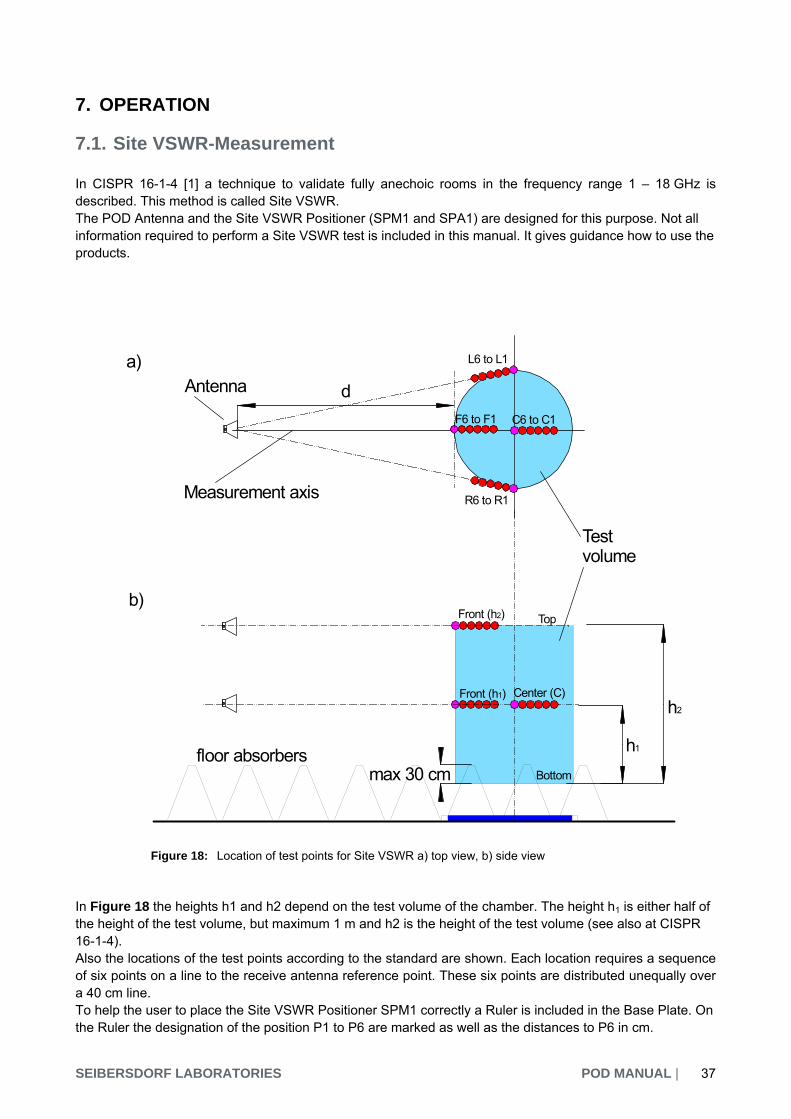
7. OPERATION 7.1. Site VSWR-Measurement In CISPR 16-1-4 [1] a technique to validate fully anechoic rooms in the frequency range 1 – 18 GHz is described. This method is called Site VSWR. The POD Antenna and the Site VSWR Positioner (SPM1 and SPA1) are designed for this purpose. Not all information required to perform a Site VSWR test is included in this manual. It gives guidance how to use the products. Figure 18: Location of test points for Site VSWR a) top view, b) side view In Figure 18 the heights h1 and h2 depend on the test volume of the chamber. The height h1 is either half of the height of the test volume, but maximum 1 m and h2 is the height of the test volume (see also at CISPR 16-1-4). Also the locations of the test points according to the standard are shown. Each location requires a sequence of six points on a line to the receive antenna reference point. These six points are distributed unequally over a 40 cm line. To help the user to place the Site VSWR Positioner SPM1 correctly a Ruler is included in the Base Plate. On the Ruler the designation of the position P1 to P6 are marked as well as the distances to P6 in cm.
d
Measurement axis
Testvolume
F6 to F1
L6 to L1
R6 to R1
Antenna
h1
Top
floor absorbers
h2
a)
b)
max 30 cm
Front (h1)
C6 to C1
Center (C)
Front (h2)
Bottom

| POD MANUAL SEIBERSDORF LABORATORIES 38
The Ruler should be used with the SPM1 in the following way: Mark the reference points for each location on the turntable. Depending on the location different positions act as reference. F6 and C6 are the reference for the location front and center, R1 and L1 are the reference for the location right and left.
Stick the Ruler on the turntable to form a line between the reference point and the receive antenna. Take care that the furthest position to the antenna is always P1.
To place the antenna move the Base Plate along the Ruler until the slot of the Base Plate is aligned with the desired mark on the Ruler.
The POD Antenna is mounted correctly to the Positioner when the red 0° marker points towards the receive antenna in horizontal polarization. When changing to vertical polarization the blue 180° marker will point towards the receive antenna. It is NOT necessary to turn the antenna back to the red marker. Due to the superior H-plane performance the POD Antenna is compliant to the standard in both orientations. In semi-anechoic chambers it’s allowed to cover the bottom of the test volume with absorbing material during Site VSWR test. In this case you have to place the absorbers on the top of the Base Plate of the Positioner. For Site VSWR measurements the dynamic range of the instrumentation is an important issue. The received signal should be kept at least 20 dB over the noise floor. Especially in the frequency range 6 to 18 GHz this can cause some difficulties.

SEIBERSDORF LABORATORIES POD MANUAL | 39
Following points should be kept in mind: RF cable loss can be quite large - reduce the cable length to a minimum. Using a high gain antenna will increase the received voltage for the location front and center. The
received voltages in the side points R and L will drop dramatically if the diameter of the volume is large. Reducing the resolution bandwidth on the spectrum analyzer will reduce the noise floor. A coupling of the
local oscillators of signal general and spectrum analyzer via a 10 MHz link may be necessary. The use of a low noise preamplifier can increase the received voltage. The noise floor will also be
amplified dramatically if the noise figure is too high. 7.2. Field Strength Measurements For doing accurate field strength measurements, it is very important to keep conductive and massive dielectric elements away from the POD Antenna.
dBdBdB/mVdBV/mdB amplifiercablePODreceiver GAINATTAFUE
To indicate the field strength the antenna factor and the cable loss should be added to the receiver reading. When a preamplifier is used, the gain has to be subtracted. 7.3. Add3D Field Strength Measurements Using sPOD Antennas The Add3D method developed by Seibersdorf Laboratories is based on broadband antennas with a dipole-like radiation pattern and frequency selective voltage measurements performed in three orthogonal directions [6]. Therefore the effective field strength EAdd3D can be obtained from such frequency selective voltage measurements by adding this three components (e.g.: x-, y- and z- axis) of the measurement.
sPODzyxDAdd AFUUUmVdBE 2223 log20/
In this formula Ux, Uy and Uz is given in µV and the AFsPOD in dB/m. Big advantages of the Add3D method are to enable frequency selective measurements over a wide frequency range with high sensitivity and a spatial isotropic radiation pattern considering if the three voltage measurements are considered as described above. Therefore this method became very popular for EMF-evaluation during past years. Due to their excellent dipole-like radiation pattern the POD antennas are perfectly suited to perform measurements according the Add3D method. To make the positioning in the three orthogonal axes easy we developed the sPOD (shortened POD) antennas, with a total length of only 30 cm8. The technical data are very similar compared to the longer, original POD antennas.
8 This sPOD antenna is NOT intended for Site VSWR measurements

| POD MANUAL SEIBERSDORF LABORATORIES 40
Specification sPOD 16 sPOD 618
Frequency range 1 - 6 GHz 6 - 18 GHz
Typical antenna factor 37 - 49 dB/m 49 - 59 dB/m
Typical VSWR < 2.0
Phase center center of radome
Connector type SMA female
Total antenna length 300 mm
Radome tip to phase center 50 mm
Diameter handle 30 mm
Antenna weight ~ 175 g ~ 140 g
Max. input RF-power 30 dBm
Field strength damage level 200 V/m
Temperature operating range 5°C - 45°C
Humidity (non condensing) < 98%
Dimensions of Antenna Set 53 x 44 x 17 cm
Weight of Antenna Set ~ 5 kg9
Table 5: Technical specification of sPOD antennas To get the effective field strength on the measurement position, of course cable loss and eventually used preamplifier have to be considered. Taking these terms into account, the formula for frequency selective, isotropic EMF field strength measurements according the Add3D method using sPOD antennas becomes:
dBGAINdBATTmVdBEmVdBE amplifiercableDAdd // 3
For Add3D measurements it is not necessary to consider the red 0°-Marker (respectively the blue 180°-Marker label) in any way. However they could be used to reproduce an antenna position exactly and they are used to define the angles of E- and H-planes as indicated in the manual (e.g. necessary for the calibration of sPOD antennas).
9 Including rotator for Add3D measurements

SEIBERSDORF LABORATORIES POD MANUAL | 41
Figure 19: sPod mounted on a Field Nose rotator for Add3D measurements In Figure 19 a sPOD antenna is shown, mounted on a rotator (automatic or manual can be used) of the Field Nose system to perform Add3D measurements. To mount the antenna on the rotator: Slide the sPOD antenna carefully into the black holder until the spacer touches the blue radom of the
sPOD. This position assures that the centre of the antennas radiation elements is accurately in the rotation axis.
Fix the antenna with the metal part of the holder and Connect the RF-cable to the antenna. Finally mount the holder with the sPOD antenna at the rotator using the small metal screw.

| POD MANUAL SEIBERSDORF LABORATORIES 42
8. LITERATURE AND INFORMATION [1] CISPR 16-1-4 Amd. 1 Ed.3 , Specification for radio disturbance and immunity measuring apparatus
and methods - Part 1-4: Radio disturbance and immunity measuring apparatus - Ancillary equipment - Radiated disturbances.
[2] CISPR 22 Ed. 6.0: “Information technology equipment - Radio disturbance characteristics - Limits and
methods of measurement ”, International Electrotechnical Commission IEC, Consolidated Edition 5.2, 2006-03
[3] Alexander Kriz, Wolfgang Müllner: „Validierung von EMV Emissionsmessplätzen im Frequenzbereich
1 GHz bis 18 GHz nach dem Site VSWR Verfahren“, e&i, ÖVE Verbandszeitschrift, Heft 1-2.2006 [4] Alexander Kriz: „Validating Anechoic Chambers Above 1 GHz Using a Reciprocal Site VSWR
Technique“, 2005 IEEE International EMC Symposium, 8. – 12. August 2005, Chicago IL USA [5] Alexander Kriz: „Influence of H-Plane Pattern Performance of the Omnidirectional Transmit Antenna to
the Site VSWR Result“, 2006 IEEE International EMC Symposium, 14. – 18. August 2006, Portland OR USA
[6] Wolfgang Müllner, Georg Neubauer, Harald Haider: “Add3D, a new technique for precise power flux
density measurements at mobile communications base stations" Presentation, 8. Internationale Fachmesse und Kongress für Elektromagnetische Verträglichkeit, 22 – 24 Februar 2000, Düsseldorf

SEIBERSDORF LABORATORIES POD MANUAL | 43
9. FIGURES Figure 1: Schematic drawing of POD Antenna construction ....................................................................... 6 Figure 2: Radiation pattern (yellow) for different dipole antenna designs (black) in E- and H-Plane. ........ 7 Figure 3: Normalized E- and H-plane radiation pattern results for a POD 16 at 4 GHz and forbidden ...... 7 Figure 4: Site VSWR Positioner .................................................................................................................. 8 Figure 5: Available sets for Site-VSWR evaluation ..................................................................................... 9 Figure 6: POD Antenna Set ........................................................................................................................ 9 Figure 7: Components of SPA1 automatic Site VSWR Positioner ........................................................... 10 Figure 8: Components of SPM1 manual Site VSWR Positioner ............................................................... 10 Figure 9: Components of Site VSWR Positioners ..................................................................................... 11 Figure 10: Site VSWR Set with SPM1 manual Site VSWR Positioner ....................................................... 11 Figure 11: Site VSWR Set with SPM1 manual Site VSWR Positioner ....................................................... 12 Figure 12: Typical Calibration data for POD 16 .......................................................................................... 14 Figure 13: Typical Calibration data for POD 618 ........................................................................................ 15 Figure 14: Definition of E- and H-planes for the radiation pattern diagrams ............................................... 16 Figure 15: Radiation Pattern POD 16 ......................................................................................................... 18 Figure 16: Radiation Pattern POD 618 ....................................................................................................... 23 Figure 17: Site VSWR Positioner for measuring at h1 (e.g. 100 cm) and h2 (e.g. 200 cm) ........................ 25 Figure 18: Location of test points for Site VSWR a) top view, b) side view ................................................ 37 Figure 19: sPod mounted on a Field Nose rotator for Add3D measurements ............................................ 41

| POD MANUAL SEIBERSDORF LABORATORIES 44
10. TABLES Table 1: Technical specifications of POD Antennas ................................................................................ 13 Table 2: Typical antenna factor and VSWR for POD 16 .......................................................................... 14 Table 3: Typical antenna factor and VSWR for POD 618 ........................................................................ 15 Table 4: Specifications of Site VSWR Positioners ................................................................................... 24 Table 5: Technical specification of sPOD antennas ................................................................................ 40

SEIBERSDORF LABORATORIES POD MANUAL | 45
ANNEX I. WARRANTY Seibersdorf Labor GmbH, hereinafter referred to as the Seller, warrants that standard Seibersdorf Laboratories products are free from defect in materials and workmanship for a period of two (2) years from the date of shipment. Standard Seibersdorf Laboratories products include the following: Antennas Cables Reference Radiators Software Antenna stands and positioners If the Buyer notifies the Seller of a defect within the warranty period, the Seller will, at the Seller’s option, either repair and/or replace products which prove to be defective during the warranty period. There will be no charge for warranty services performed at the location the Seller designates. The Buyer must, however, prepay inbound shipping costs and any duties or taxes. The Seller will pay outbound shipping cost for a carrier of the Seller’s choice, exclusive of any duties or taxes. This warranty does not apply to: Normal wear and tear of materials Consumable items such as fuses, batteries, etc. Products that have been improperly installed, maintained or used Products which have been operated outside the specifications Products which have been modified without authorization Calibration of products, unless necessitated by defects THIS WARRANTY IS EXCLUSIVE. NO OTHER WARRANTY, WRITTEN OR ORAL, IS EXPRESSED OR IMPLIED, INCLUDING BUT NOT LIMITED TO, THE IMPLIED WARRANTIES OF MERCHANTABILITY AND FITNESS FOR A PARTICULAR PURPOSE. THE REMEDIES PROVIDED BY THIS WARRANTY ARE THE BUYER’S SOLE AND EXCLUSIVE REMEDIES. IN NO EVENT IS THE SELLER LIABLE FOR ANY DAMAGES WHATSOEVER, INCLUDING BUT NOT LIMITED TO, DIRECT, INDIRECT, SPECIAL, INCIDENTAL, OR CONSEQUENTIAL DAMAGES, WHETHER BASED ON CONTRACT, TORT, OR ANY OTHER LEGAL THEORY.

| POD MANUAL SEIBERSDORF LABORATORIES 46
ANNEX II. Sample Certificate of Antenna Calibration A sample ÖKD 13 certificate for the POD 16 is given on the following pages. It contains the calibration of antenna factor, VSWR and radiation pattern.

ÖSTERREICHISCHER KALIBRIERDIENST AKKREDITIERT DURCH DAS BUNDESMINISTERIUM für WIRTSCHAFT, FAMILIE und JUGEND Kalibrierlaboratorium für Antennen und Feldsonden Calibration laboratory for antennas and field probes KALIBRIERSCHEIN EH-A xx/09 KALIBRIERZEICHEN CALIBRATION CERTIFICATE CALIBRATION MARK
Gegenstand Object
Precision Omnidirectional Dipole
Hersteller Manufacturer
Seibersdorf Laboratories
Typ Type
POD 16
Herstellernummer Serial number
SN xxx
Auftraggeber Customer
Seibersdorf Labor GmbH 2444 Seibersdorf Austria
Auftragsnummer Order Nr.
L.L7.00013.0.0 - P-XXX
Anzahl der Seiten des Kalibrierscheines Number of pages of the certificate Datum der Kalibrierung Date of calibration
1 - 5 1.7.2009
Dieser Kalibrierschein darf nur vollständig und unverändert weiterverarbeitet werden. Auszüge oder Änderungen sind unzulässig. Kalibrierscheine ohne Unterschrift und Stempel haben keine Gültigkeit. This calibration certificate may not be reproduced other than in full. Calibration certificates without signature and seal are not valid. Stempel Datum Leiter des Kalibrierlaboratoriums Bearbeiter Seal Date Head of the calibration laboratory Person responsible 1.7.2009 ___________________________ _____________________ Seibersdorf Labor GmbH | 2444 Seibersdorf, Austria | Tel.: +43 (0) 50550-2500 | Fax: +43 (0) 50550-2502 | Mail: [email protected] www.seibersdorf-laboratories.at | Landesgericht Wiener Neustadt | FN 319187v | DVR: 4000728 | UID: ATU64767504 | Steuernummer: 192/6571 | Zertifiziert nach ISO 9001:2000 Bankverbindung: Erste Bank der Österreichischen Sparkassen AG | BLZ 20111 | Konto Nr. 291-140-380/00 | IBAN AT112011129114038000 | BIC GIBAATWW
EH-A xx/09
ÖKD 13 1.7.2009
Der Österreichische Kalibrierdienst ist Unterzeichner des Multilateralen Übereinkommens der European Cooperation for Accreditation (EA) zur gegenseitigen Anerkennung von Kalibrierscheinen und Mitglied der International Laboratory Accreditation Cooperation (ILAC). Die Kalibrierung erfolgt auf der gesetzlichen Grundlage der §§ 58 und 59 des Maß- und Eichgesetzes BGBL. Nr. 152/1950 in gültiger Fassung. Dieser Kalibrierschein dokumentiert die Rückführ-barkeit auf nationale Normale zur Darstellung der physikalischen Einheiten in Übereinstimmung mit dem Internationalen Einheitensystem (SI). Für die Einhaltung einer angemessenen Frist zur Wiederholung der Kalibrierung ist der Benutzer verantwortlich. The Österreichische Kalibrierdienst is signatory to the multilateral agreement of the European Co-operation for Accreditation (EA) for mutual recognition of calibration certificates and member of the International Laboratory Accreditation Cooperation (ILAC). The calibration is performed in accordance with the law concerning legal metrology, federal gazette Nr. 152/1950, last amended with federal gazette Nr. 468/1992. This calibration certificate documents the trace-ability to national standards, which realise the physical units of measurements according to the International system of Units (SI). The user is obliged to have the object recalibrated at appropriate intervals.

Page 2 of 5
EH-A xx/09
ÖKD 13 1.7.2009
Measurement Procedures: The Antenna Factor is determined in the 0° orientation using the 3 Antenna Method. The calibration distance is 1.5 m within the fully environment. The VSWR (Voltage Standing Wave Ratio) is measured with a network analyser within the anechoic environment. The Radiation Pattern is measured in the anechoic environment. The AUC is placed on a turntable which is rotated by 360° in 1° steps. An electric field of 1 V/m is generated by a broadband transmit antenna and the fieldstrength received by the AUC is recorded as a function of angle and frequency in 2 m distance. Both, E- and H-Plane pattern are measured. The following Figure shows a POD Antenna and visualizes the E- and the H-plane. Also the angles ϑ and ϕ used for the radiation pattern diagrams and the 0°-orientation used for the antenna factor calibration are defined.
A normalization of the radiation pattern is required by the standard. This is necessary to apply the criteria and is performed for each pattern. For E-plane and H-plane this is done in a different manner: • E-plane: The pattern is normalized to the largest value (0 dB) • H-plane: The mean value of the pattern is calculated in an angular range from -135° to
+135°. The full pattern (angular range ±180°) is normalized to this average (0 dB).
Test Equipment Type IdentificationHP 8722C Network Analyser E0123 HP 85052D 3.5 mm Calibration Kit E0116 POD16 Reference Antenna E1639 POD618 Reference Antenna E1640 Preamplifier (LNA) E0738 Cable E4864 Cable E4865

Page 3 of 5
EH-A xx/09
ÖKD 13 1.7.2009
Dates Date of calibration: 1.7.2009 Date of completion: 1.7.2009 Environmental Conditions Test Site Temperature 21 °C Test Site Humidity 30 % Control Room Temperature 22 °C Control Room Humidity 32 % Results The results are given in the following tables and figures. In the Radiation Pattern diagrams the performance criteria given by the standard [1] are also shown and met for all frequencies and polarisations.
Frequency Antenna Factor [dB/m] VSWR [1]1 1 38.9 1.7 2 40.1 1.5 3 43.6 1.6 4 45.7 1.5 5 47.5 1.5 6 49.0 1.4
Accuracy of Calibration The associated expanded uncertainty of the measured antenna factors and radiation pattern is ± 1.6 dB with respect to the given procedures. Any quoted uncertainty refers only to the measured value at the time of calibration and does not carry any implication regarding the long-term stability of the antennas. Results are valid for the specified antenna at the time of calibration. The reported expanded uncertainty of measurement is stated as the standard uncertainty of measurement multiplied by the coverage factor k = 2, which for a normal distribution corresponds to a coverage probability of approximately 95%. The standard uncertainty of measurement has been determined in accordance with EA 4/02 [2]. References [1] CISPR 16-1-4 Ed.2 (Feb. 2007): Specification for radio disturbance and immunity
measuring apparatus and methods - Part 1-4: Radio disturbance and immunity measuring apparatus - Ancillary equipment - Radiated disturbances.
[2] EA 02/04: "Expression of the Uncertainty of Measurement in Calibration", EA
European co-operation for Accreditation, December 1999
1 The VSWR calibration for frequencies higher than 1 GHz is out of scope of accreditation

Page 4 of 5
EH-A xx/09
ÖKD 13 1.7.2009
E-Plane H-Plane
1 G
Hz
2 G
Hz
3 G
Hz

Page 5 of 5
EH-A xx/09
ÖKD 13 1.7.2009
E-Plane H-Plane
4 G
Hz
5 G
Hz
6 G
Hz


CONTACTSeibersdorf Labor GmbH
RF Engineering2444 Seibersdorf, Austria
www.seibersdorf-laboratories.at/rfFax: +43 (0) 50550 - 2881