manual placa mãe gf7050vt-m5 v1.0
TRANSCRIPT


Preface
PrefaceCopyrightThis publication, including all photographs, illustrations and software, is protectedunder international copyright laws, with all rights reserved. Neither this manual, norany of the material contained herein, may be reproduced without written consent ofthe author.
Version 1.0A
DisclaimerThe information in this document is subject to change without notice. The manufac-turer makes no representations or warranties with respect to the contents hereof andspecifically disclaims any implied warranties of merchantability or fitness for anyparticular purpose. The manufacturer reserves the right to revise this publication andto make changes from time to time in the content hereof without obligation of themanufacturer to notify any person of such revision or changes.
Trademark RecognitionMicrosoft, MS-DOS and Windows are registered trademarks of Microsoft Corp.
nVIDIA is a registered trademark of nVIDIA Corporation..
Other product names used in this manual are the properties of their respectiveowners and are acknowledged.
Federal Communications Commission (FCC)This equipment has been tested and found to comply with the limits for a Class Bdigital device, pursuant to Part 15 of the FCC Rules. These limits are designed toprovide reasonable protection against harmful interference in a residential installa-tion. This equipment generates, uses, and can radiate radio frequency energy and, ifnot installed and used in accordance with the instructions, may cause harmful inter-ference to radio communications. However, there is no guarantee that interferencewill not occur in a particular installation. If this equipment does cause harmfulinterference to radio or television reception, which can be determined by turning theequipment off and on, the user is encouraged to try to correct the interference by oneor more of the following measures:
• Reorient or relocate the receiving antenna• Increase the separation between the equipment and the receiver• Connect the equipment onto an outlet on a circuit different from that to
which the receiver is connected• Consult the dealer or an experienced radio/TV technician for help
Shielded interconnect cables and a shielded AC power cable must be employed withthis equipment to ensure compliance with the pertinent RF emission limits governingthis device. Changes or modifications not expressly approved by the system’s manu-facturer could void the user’s authority to operate the equipment.
ii
Preface
Declaration of ConformityThis device complies with part 15 of the FCC rules. Operation is subject to thefollowing conditions:
• This device may not cause harmful interference, and• This device must accept any interference received, including interfer-
ence that may cause undesired operation
Canadian Department of CommunicationsThis class B digital apparatus meets all requirements of the Canadian Interference-causing Equipment Regulations.
Cet appareil numérique de la classe B respecte toutes les exigences du Réglement surle matériel brouilieur du Canada.
About the ManualThe manual consists of the following:
Chapter 1
Introducing the Motherboard
Chapter 2
Installing the Motherboard
Chapter 3
Using BIOS
Chapter 4
Using the Motherboard Software
Describes features of themotherboard.
Go to page 1
Describes installation ofmotherboard components.
Go to page 7
Provides information on us-ing the BIOS Setup Utility.
Go to page 27
Describes the motherboardsoftware
Go to page 43
Chapter 5
Setting Up NVIDIA RAID Configuration
Provides information aboutSATA RAID Setup
Go to page 49
iii
Chapter 3 27Using BIOS 27
About the Setup Utility................................................................ 27The Standard Configuration..............................................27Entering the Setup Utility....................................................27
Using BIOS......................................................................................28Standard CMOS Setup......................................................29Advanced Setup.................................................................31Advanced Chipset Setup....................................................33
TTTTTABLE OF CONTENTSABLE OF CONTENTSABLE OF CONTENTSABLE OF CONTENTSABLE OF CONTENTSPreface i
Chapter 1 1Introducing the Motherboard 1
Introduction......................................................................................1Feature ..............................................................................................2Motherboard Components.............................................................4
Chapter 2 7 7 7 7 7Installing the Motherboard 7
Safety Precautions.............................................................................7Choosing a Computer Case..............................................................7Installing the Motherboard in a Case.............................................7Checking Jumper Settings................................................................8
Setting Jumpers.........................................................................8Checking Jumper Settings.........................................................9Jumper Settings.........................................................................9
Installing Hardware..........................................................................10Installing the Processor...........................................................10Installing Memory Modules.....................................................12
Expansion Slots.......................................................................14 Connecting Optional Devices..................................................16
Installing a Hard Disk Drive/CD-ROM/SATA Hard Drive......19Installing a Floppy Diskette Drive...........................................20
Connecting I/O Devices...............................................................21 Connecting Case Components.......................................................22
Front Panel Header...................................................................24
iv
Integrated Peripherals.......................................................34Power Management Setup.................................................35PCI/PNP Configuration.....................................................37PC Health Status................................................................37Frequency/Voltage Control.................................................39Load Default Settings.......................................................40
Supervisor Password.........................................................40User Password...................................................................41Save & Exit Setup...............................................................41Exit Without Saving.............................................................41Updating the BIOS..............................................................42
Chapter 4 43 43 43 43 43Using the Motherboard Software 43
About the Software CD-ROM......................................................43Auto-installing under Windows XP/Vista..................................43
Running Setup....................................................................44Manual Installation........................................................................48Utility Software Reference............................................................48
Chapter 5 49 49 49 49 49Setting Up NVIDIA RAID Configuration 49
Setting Up a Non-Bootable RAID Array....................................49 Setting Up a Bootable RAID Array.............................................51
1
Introducing the Motherboard
Chapter 1Introducing the Motherboard
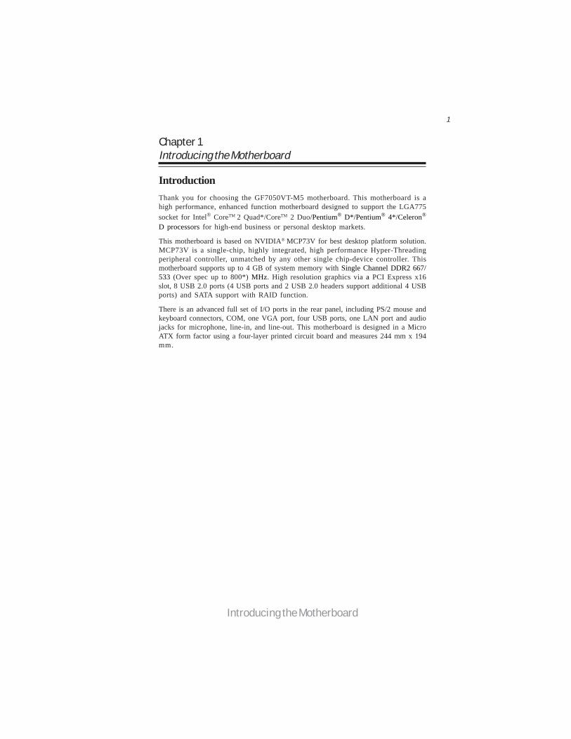
IntroductionThank you for choosing the GF7050VT-M5 motherboard. This motherboard is ahigh performance, enhanced function motherboard designed to support the LGA775socket for Intel® CoreTM 2 Quad*/CoreTM 2 Duo/Pentium® D*/Pentium® 4*/Celeron®
D processors for high-end business or personal desktop markets.
This motherboard is based on NVIDIA® MCP73V for best desktop platform solution.MCP73V is a single-chip, highly integrated, high performance Hyper-Threadingperipheral controller, unmatched by any other single chip-device controller. Thismotherboard supports up to 4 GB of system memory with Single Channel DDR2 667/533 (Over spec up to 800*) MHz. High resolution graphics via a PCI Express x16slot, 8 USB 2.0 ports (4 USB ports and 2 USB 2.0 headers support additional 4 USBports) and SATA support with RAID function.
There is an advanced full set of I/O ports in the rear panel, including PS/2 mouse andkeyboard connectors, COM, one VGA port, four USB ports, one LAN port and audiojacks for microphone, line-in, and line-out. This motherboard is designed in a MicroATX form factor using a four-layer printed circuit board and measures 244 mm x 194mm.
2
Introducing the Motherboard
FeatureProcessor
• Accommodates Intel® CoreTM 2 Quad*/CoreTM 2 Duo/Pentium® D*/Pentium® 4*/Celeron® D processors
• Supports a system bus (FSB) of 1333/1066/800 MHz• Supports “Hyper-Threading” technology CPU
“Hyper-Threading” technology enables the operating system into thinking it’shooked up to two processors, allowing two threads to be run in parallel, both onseparate “logical” processors within the same physical processor.
The motherboard uses an LGA775 type of Intel® CoreTM 2 Quad*/CoreTM 2 Duo/Pentium® D*/Pentium® 4*/Celeron® D that carries the following features:
• DDR2 667/533 (Over spec up to 800*) DDR SDRAM with Single Chan-nel supported
• Accommodates two unbuffered DIMMs• Up to 2 GB per DIMM with maximum memory size up to 4 GB
Memory
Audio• 6 Channels of DAC support 16/20/24-bit PCM Format for 5.1 Audio
Solution• All ADCs support 48k/192k Independent Sample Rate• Exceeds Microsoft PC2001 Requirement• High Quality Differential CD input• Power Support: Digital: 3.3V; Analog: 3.3V/5.0V
The NVIDIA® MCP73V is a single-chip with proven reliability and performance.
• Supports 33-bit addressing for access to 8 GB of system memory• PCI Express 16-lane link interface for external graphics processors• PCI 2.3 interface at 33 MHz• Integrated SATA 3.0 Gb/s Host Controller• USB 2.0 ports supported• Fast ATA-133 IDE controller
Chipset
1. “ * ” stands for this motherboard is ready to support Intel® CoreTM
2 Quad/ Pentium® D/Pentium® 4 processor and over spec to sup-port DDR2 800.
2. To reach DDR2 800, users please make sure that “System ClockMode” in “Frequency/Voltage Control” should be selected to “Un-linked” manually since the Auto-run is DDR2 667.

3
Introducing the Motherboard
1. Some hardware specifications and software items are subject to changewithout prior notice.2. Due to chipset limitation, we recommend that motherboard be oper-ated in the ambiance between 0 and 50 °C.
Integrated I/O
• Two PS/2 ports for mouse and keyboard• One serial port• One VGA port• Four USB ports• One LAN port• Audio jacks for microphone, line-in and line-out
The motherboard has a full set of I/O ports and connectors:
This motherboard supports Ultra DMA bus mastering with transfer rates of 133/100/66/33 Mb/s.
• One PCI Express x16 for Graphics Interface• One PCI Express x1 slot• Two 32-bit PCI v2.3 compliant slots• One IDE connector supporting up to two IDE devices• One floppy disk drive interface• Four 7-pin SATA connectors
Expansion OptionsThe motherboard comes with the following expansion options:
BIOS Firmware
• Power management• Wake-up alarms• CPU parameters• CPU and memory timing
The motherboard uses AMI BIOS that enables users to configure many systemfeatures including the following:
The firmware can also be used to set parameters for different processor clockspeeds.
Onboard LANThe onboard LAN provides the following features:
• 10/100 Mb/s dual speed transceiver• MII interface for external MAC devices• 10/100 Mb/s IEEE 802.3 compliant• IEEE 802.3 Auto-Negotiation

4
Introducing the Motherboard
Motherboard Components

5
Introducing the Motherboard
Table of Motherboard Components
This concludes Chapter 1. The next chapter explains how to install the motherboard.
LABEL COMPONENTS
LGA775 socket for Intel® CoreTM2 Quad*/CoreTM2 Duo/Pentium® D*/Pentium® 4*/Celeron® D CPUs
2. CPU_FAN CPU cooling fan connector3. DDR2_1~2 240-pin DDR2 SDRAM slots4. ATX_POWER Standard 24-pin ATX pow er connector5. SYS_FAN System cooling fan connector6. SATA1~4 Serial ATA connectors7. SPK Speaker header8. LPT Onboard parallel port header9. CLR_CMOS Clear CMOS jumper10. F_PANEL Front panel sw itch/LED header11. IDE Primary IDE connector12. FDD Floppy disk drive connector13. F_USB1~2 Front Panel USB headers14. USBPWR_F Front Panel USB Pow er Select Jumper15. CD_IN Analog audio input header16. F_AUDIO Front panel audio header17. PCI1~2 32-bit add-on card slots18. SPDIFO SPDIF out header19. PCIEX16 PCI Express slot for graphics interface20. PCIE PCI Express x1 slot21. USBPWR_R Real Panel USB PS/2 Pow er Select Jumper22. ATX12V Auxiliary 4-pin pow er connector
1. CPU Socket

6
Introducing the Motherboard
Memo

7
Installing the Motherboard
Chapter 2Installing the Motherboard
Safety Precautions• Follow these safety precautions when installing the motherboard• Wear a grounding strap attached to a grounded device to avoid dam-
age from static electricity• Discharge static electricity by touching the metal case of a safely
grounded object before working on the motherboard• Leave components in the static-proof bags they came in• Hold all circuit boards by the edges. Do not bend circuit boards
Choosing a Computer CaseThere are many types of computer cases on the market. The motherboard complieswith the specifications for the Micro ATX system case. Firstly, some features on themotherboard are implemented by cabling connectors on the motherboard to indica-tors and switches on the system case. Make sure that your case supports all thefeatures required. Secondly, this motherboard supports one floppy diskette drive andone enhanced IDE drive. Make sure that your case has sufficient power and space forall drives that you intend to install.
Most cases have a choice of I/O templates in the rear panel. Make sure that the I/Otemplate in the case matches the I/O ports installed on the rear edge of themotherboard.
This motherboard carries an Micro ATX form factor of 244 x 194 mm. Choose acase that accommodates this form factor.
Installing the Motherboard in a CaseRefer to the following illustration and instructions for installing the motherboard ina case.
Most system cases have mounting brackets installed in the case, which correspondthe holes in the motherboard. Place the motherboard over the mounting bracketsand secure the motherboard onto the mounting brackets with screws.
Ensure that your case has an I/O template that supports the I/O ports and expansionslots on your motherboard.
8
Installing the Motherboard
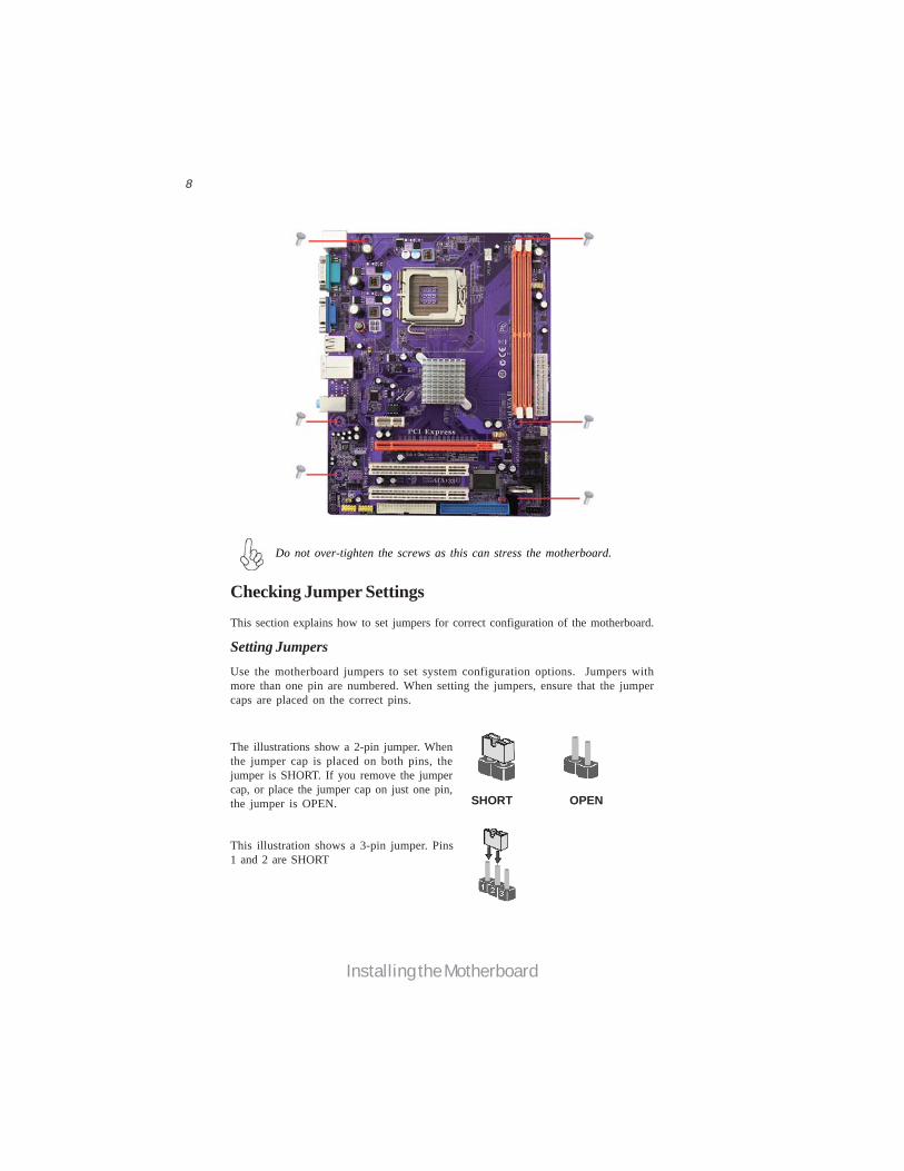
Checking Jumper SettingsThis section explains how to set jumpers for correct configuration of the motherboard.
Setting JumpersUse the motherboard jumpers to set system configuration options. Jumpers withmore than one pin are numbered. When setting the jumpers, ensure that the jumpercaps are placed on the correct pins.
The illustrations show a 2-pin jumper. Whenthe jumper cap is placed on both pins, thejumper is SHORT. If you remove the jumpercap, or place the jumper cap on just one pin,the jumper is OPEN.
This illustration shows a 3-pin jumper. Pins1 and 2 are SHORT
SHORT OPEN
Do not over-tighten the screws as this can stress the motherboard.

9
Installing the Motherboard
Checking Jumper SettingsThe following illustration shows the location of the motherboard jumpers. Pin 1 islabeled.
Jumper Settings
1. To avoid the system unstability after clearing CMOS, we recommendusers to enter the main BIOS setting page to “Load Optimal Defaults”and then “Save Changes and Exit”.2. Make sure the power supply provides enough 5VSB voltage beforeselecting the 5VSB function.3. It is required that users place the USBPWR_F & USBPWR_R cap onto2-3 pin rather than 1-2 pin as default if you want to wake up the com-puter by USB/PS2 KB/Mouse.
Front PanelUSB PowerSelect Jumper USBPWR_F
USBPWR_R
Jumper Type Description Setting (default)
CLR_CMOS 3-pin Clear CMOS
1-2: NORMAL
2-3: CLEAR CMOSBefore clearing theCMOS, make sure toturn off the system.
CLR_CMOS
Rear USB/PS2Power SelectJumper
2-3: 5VSB
1-2: VCCUSBPWR_F
USBPWR_R
3-pin
3-pin
2-3: 5VSB
1-2: VCC1
1
1

10
Installing the Motherboard
Installing HardwareInstalling the Processor
Caution: When installing a CPU heatsink and cooling fan make sure thatyou DO NOT scratch the motherboard or any of the surface-mount resis-tors with the clip of the cooling fan. If the clip of the cooling fan scrapesacross the motherboard, you may cause serious damage to the motherboardor its components.
This motherboard has an LGA775 socket. When choosing a processor, consider theperformance requirements of the system. Performance is based on the processordesign, the clock speed and system bus frequency of the processor, and the quantityof internal cache memory and external cache memory.
Before installing the Processor
This motherboard automatically determines the CPU clock frequency and systembus frequency for the processor. You may be able to change the settings in the systemSetup Utility. We strongly recommend that you do not over-clock processors orother components to run faster than their rated speed.
On most motherboards, there are small surface-mount resistors near theprocessor socket, which may be damaged if the cooling fan is carelesslyinstalled.
Avoid using cooling fans with sharp edges on the fan casing and the clips.Also, install the cooling fan in a well-lit work area so that you can clearlysee the motherboard and processor socket.
Warning:
1. Over-clocking components can adversely affect the reliability of thesystem and introduce errors into your system. Over-clocking can perma-nently damage the motherboard by generating excess heat in componentsthat are run beyond the rated limits.
2. Always remove the AC power by unplugging the power cord from thepower outlet before installing or removing the motherboard or otherhardware components.
11
Installing the Motherboard
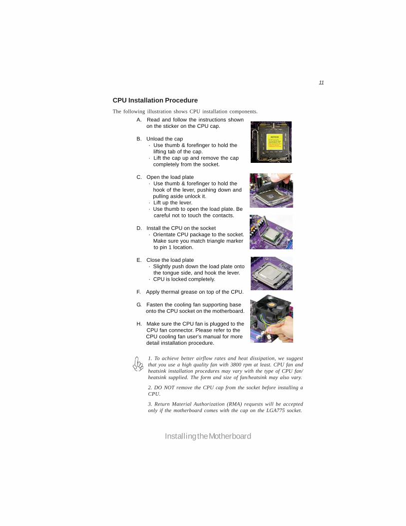
A. Read and follow the instructions shown on the sticker on the CPU cap.
B. Unload the cap· Use thumb & forefinger to hold the lifting tab of the cap.· Lift the cap up and remove the cap completely from the socket.
C. Open the load plate· Use thumb & forefinger to hold the hook of the lever, pushing down and pulling aside unlock it.· Lift up the lever.· Use thumb to open the load plate. Be careful not to touch the contacts.
D. Install the CPU on the socket· Orientate CPU package to the socket. Make sure you match triangle marker to pin 1 location.
E. Close the load plate· Slightly push down the load plate onto the tongue side, and hook the lever.· CPU is locked completely.
F. Apply thermal grease on top of the CPU.
G. Fasten the cooling fan supporting base onto the CPU socket on the motherboard.
H. Make sure the CPU fan is plugged to the CPU fan connector. Please refer to the CPU cooling fan user’s manual for more detail installation procedure.
CPU Installation ProcedureThe following illustration shows CPU installation components.
1. To achieve better airflow rates and heat dissipation, we suggestthat you use a high quality fan with 3800 rpm at least. CPU fan andheatsink installation procedures may vary with the type of CPU fan/heatsink supplied. The form and size of fan/heatsink may also vary.
2. DO NOT remove the CPU cap from the socket before installing aCPU.
3. Return Material Authorization (RMA) requests will be acceptedonly if the motherboard comes with the cap on the LGA775 socket.
12
Installing the Motherboard
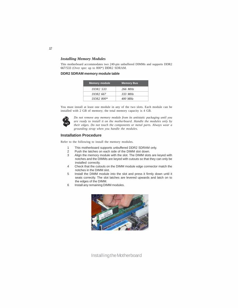
Installation ProcedureRefer to the following to install the memory modules.
1 This motherboard supports unbuffered DDR2 SDRAM only.2 Push the latches on each side of the DIMM slot down.3 Align the memory module with the slot. The DIMM slots are keyed with
notches and the DIMMs are keyed with cutouts so that they can only beinstalled correctly.
4 Check that the cutouts on the DIMM module edge connector match thenotches in the DIMM slot.
5 Install the DIMM module into the slot and press it firmly down until itseats correctly. The slot latches are levered upwards and latch on tothe edges of the DIMM.
6 Install any remaining DIMM modules.
Installing Memory ModulesThis motherboard accommodates two 240-pin unbuffered DIMMs and supports DDR2667/533 (Over spec up to 800*) DDR2 SDRAM.
Do not remove any memory module from its antistatic packaging until youare ready to install it on the motherboard. Handle the modules only bytheir edges. Do not touch the components or metal parts. Always wear agrounding strap when you handle the modules.
DDR2 SDRAM memory module table
Memory module Memory Bus
DDR2 533 266 MHz DDR2 667 333 MHz DDR2 800* 400 MHz
You must install at least one module in any of the two slots. Each module can beinstalled with 2 GB of memory; the total memory capacity is 4 GB.
13
Installing the Motherboard
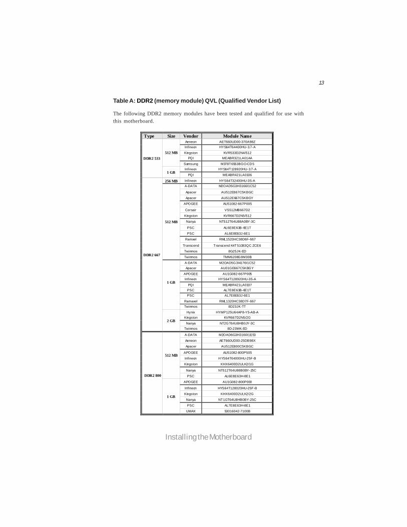
Table A: DDR2 (memory module) QVL (Qualified Vendor List)
The following DDR2 memory modules have been tested and qualified for use withthis motherboard.
Type Size Vendor Module Name Aeneon AET660UD00-370A98Z Infineon HYS64T64400HU-3.7-A
Kingston KVR533D2N4/512 PQI MEABR321LA01AA
512 MB
Samsung M378T6553BGO-CD5 Infineon HYS64T128920HU-3.7-A
DDR2 533
1 GB PQI MEABR421LA0106
256 MB Infineon HYS64T32400HU-3S-A A-DATA M2OAD5G3H3166I1C52
Apacer AU512E667C5KBGC
Apacer AU512E667C5KBGY
APOGEE AU51082-667P005
Corsair VS512MB667D2
Kingston KVR667D2N5/512
Nanya NT512T64U88A0BY-3C
PSC AL6E8E63B-6E1T
PSC AL6E8E63J-6E1
Ramxel RML1520HC38D6F-667
Transcend Transcend K4T51083QC ZCE6
Twinmos 8G25JK-ED
512 MB
Twinmos TMM6208G8M30B
A-DATA M2OAD5G3I4176I1C52 Apacer AU01GE667C5KBGY
APOGEE AU1G082-667P005 Infineon HYS64T128920HU-3S-A
PQI MEABR421LA0107 PSC AL7E8E63B-6E1T PSC AL7E8E63J-6E1
Ramaxel RML1320HC38D7F-667
1 GB
Twinmos 8D23JK-TT
Hynix HYMP125U64AP8-Y5-AB-A Kingston KVR667D2N5/2G
Nanya NT2GT64U8HB0JY-3C
DDR2 667
2 GB
Twinmos 8D-23MK-ED
A-DATA M2OAD6G3H3160I1E53
Aeneon AET660UD00-25DB98X
Apacer AU512E800C5KBGC
APOGEE AU51082-800P505
Infineon HYS64T64000HU-25F-B
Kingston KHX6400D2ULK2/1G
Nanya NT512T64U88B0BY-25C
512 MB
PSC AL6E8E63H-8E1
APOGEE AU1G082-800P000
Infineon HYS64T128020HU-25F-B
Kingston KHX6400D2ULK2/2G
Nanya NT1GT64U8HB0BY-25C
PSC AL7E8E63H-8E1
DDR2 800
1 GB
UMAX 53016042-7100B

14
Installing the Motherboard
Expansion Slots
Installing Add-on Cards
The slots on this motherboard are designed to hold expansion cards and connectthem to the system bus. Expansion slots are a means of adding or enhancing themotherboard’s features and capabilities. With these efficient facilities, you canincrease the motherboard’s capabilities by adding hardware that performs tasks thatare not part of the basic system.
PCI1~2 Slots This motherboard is equipped with two standard PCI slots. PCI standsfor Peripheral Component Interconnect and is a bus standard forexpansion cards, which for the most part, is a supplement of theolder ISA bus standard. The PCI slots on this board are PCI v2.3compliant.
Before installing an add-on card, check the documentation for the cardcarefully. If the card is not Plug and Play, you may have to manuallyconfigure the card before installation.
The PCI Express x1 slot is fully compliant to the PCI Express BaseSpecification revision 1.1 as well.
PCIE Slot
PCIEX16 Slot The PCI Express x16 slot is used to install an external PCI Expressgraphics card that is fully compliant to the PCI Express Base Speci-fication revision 1.1.
15
Installing the Motherboard
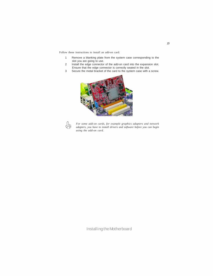
Follow these instructions to install an add-on card:
1 Remove a blanking plate from the system case corresponding to theslot you are going to use.
2 Install the edge connector of the add-on card into the expansion slot.Ensure that the edge connector is correctly seated in the slot.
3 Secure the metal bracket of the card to the system case with a screw.
For some add-on cards, for example graphics adapters and networkadapters, you have to install drivers and software before you can beginusing the add-on card.
16
Installing the Motherboard
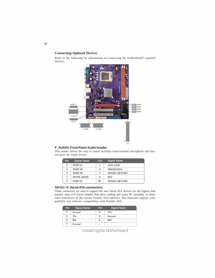
Connecting Optional DevicesRefer to the following for information on connecting the motherboard’s optionaldevices:
SATA1~4: Serial ATA connectorsThese connectors are used to support the new Serial ATA devices for the highest datetransfer rates (3.0 Gb/s), simpler disk drive cabling and easier PC assembly. It elimi-nates limitations of the current Parallel ATA interface. But maintains register com-patibility and software compatibility with Parallel ATA.
1 Ground 2 TX+3 TX- 4 Ground5 RX- 6 RX+7 Ground - -
Pin Signal Name Pin Signal Name
F_AUDIO: Front Panel Audio headerThis header allows the user to install auxiliary front-oriented microphone and line-out ports for easier access.
Pin Signal Name Function1 PORT 1L 2 AUD_GND3 PORT 1R 4 PRESENCE#5 PORT 2R 6 SENSE1_RETURN7 SENSE_SEND 8 KEY
Pin Signal Name
9 PORT 2L 10 SENSE2_RETURN
Pin Signal Name
17
Installing the Motherboard
F_USB1~2: Front Panel USB headersThe motherboard has four USB ports installed on the rear edge I/O port array.Additionally, some computer cases have USB ports at the front of the case. If youhave this kind of case, use auxiliary USB connector to connect the front-mountedports to the motherboard.
Please make sure that the USB cable has the same pin assignment asindicated above. A different pin assignment may cause damage or systemhang-up.
1 USBPWR Front Panel USB Power2 USBPWR Front Panel USB Power3 USB_FP_P0- USB Port 0 Negative Signal4 USB_FP_P1- USB Port 1 Negative Signal5 USB_FP_P0+ USB Port 0 Positive Signal6 USB_FP_P1+ USB Port 1 Positive Signal7 GND Ground
8 GND Ground9 Key No pin
10 NC Not connected
FunctionPin Signal Name
SPDIFO: SPDIF out headerThis is an optional header that provides an S/PDIF (Sony/Philips Digital Interface)output to digital multimedia device through optical fiber or coaxial connector.
1 SPDIF SPDIF digital output2 +5VA 5V analog Power
3 Key No pin4 GND Ground
Pin Signal Name Function
CD_IN: CD Audio In connector
4 CD_R CD Audio in right channel
Pin Signal Name Function1 CD_L CD Audio in left channel2 GND Ground3 GND Ground
FunctionPin Signal Name

18
Installing the Motherboard
LPT: Onboard parallel port headerThis is a header that can be used to connect to the printer, scanner or other devices.
1 STROBE 14 ALF2 PD0 15 ERROR3 PD1 16 INIT4 PD2 17 SLCTIN5 PD3 18 Ground6 PD4 19 Ground7 PD5 20 Ground
Pin Signal Name Pin Signal Name
8 PD6 21 Ground9 PD7 22 Ground10 ACK 23 Ground11 BUSK 24 Ground12 PE 25 Ground13 SLCT 26 Key
19
Installing the Motherboard
IDE devices enclose jumpers or switches used to set the IDE device as MASTER orSLAVE. Refer to the IDE device user’s manual. Installing two IDE devices on onecable, ensure that one device is set to MASTER and the other device is set to SLAVE.The documentation of your IDE device explains how to do this.
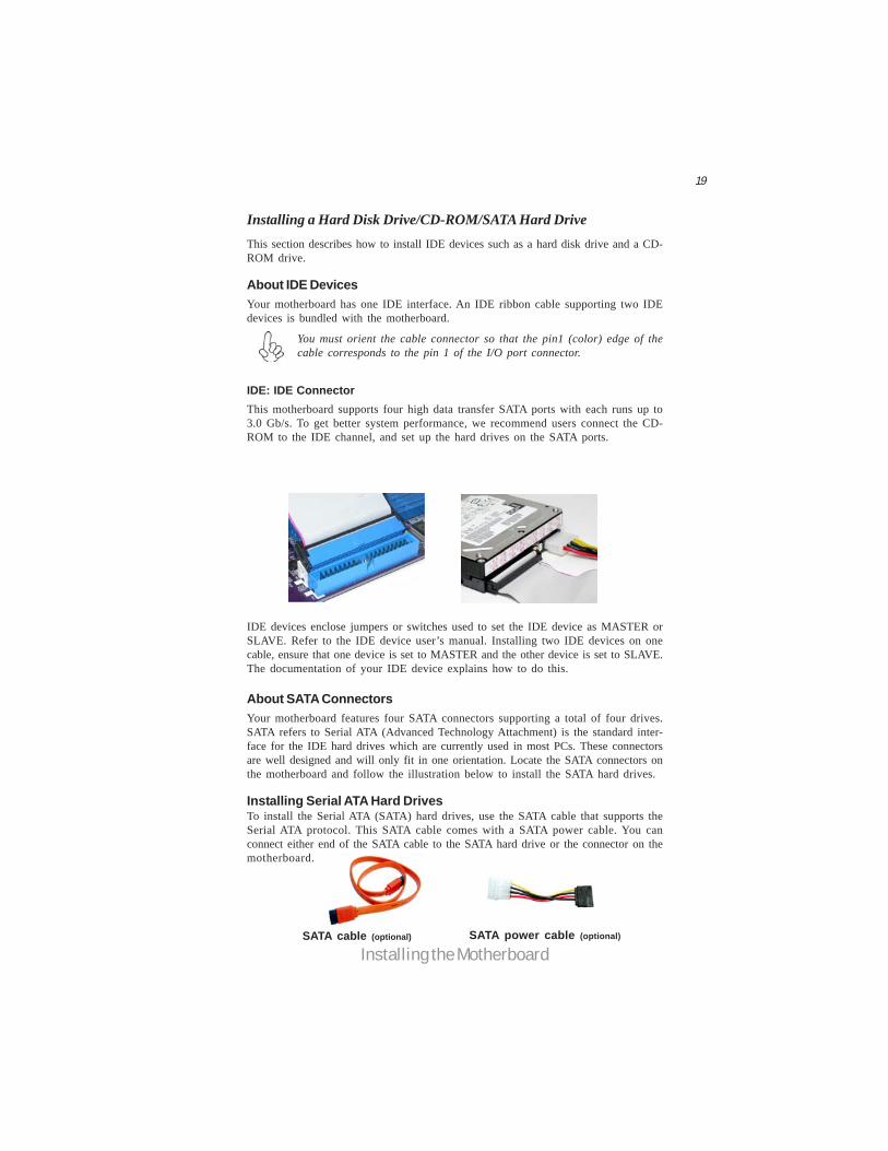
Installing a Hard Disk Drive/CD-ROM/SATA Hard DriveThis section describes how to install IDE devices such as a hard disk drive and a CD-ROM drive.
About IDE DevicesYour motherboard has one IDE interface. An IDE ribbon cable supporting two IDEdevices is bundled with the motherboard.
You must orient the cable connector so that the pin1 (color) edge of thecable corresponds to the pin 1 of the I/O port connector.
About SATA ConnectorsYour motherboard features four SATA connectors supporting a total of four drives.SATA refers to Serial ATA (Advanced Technology Attachment) is the standard inter-face for the IDE hard drives which are currently used in most PCs. These connectorsare well designed and will only fit in one orientation. Locate the SATA connectors onthe motherboard and follow the illustration below to install the SATA hard drives.
Installing Serial ATA Hard DrivesTo install the Serial ATA (SATA) hard drives, use the SATA cable that supports theSerial ATA protocol. This SATA cable comes with a SATA power cable. You canconnect either end of the SATA cable to the SATA hard drive or the connector on themotherboard.
SATA cable (optional) SATA power cable (optional)
IDE: IDE ConnectorThis motherboard supports four high data transfer SATA ports with each runs up to3.0 Gb/s. To get better system performance, we recommend users connect the CD-ROM to the IDE channel, and set up the hard drives on the SATA ports.

20
Installing the Motherboard
Refer to the illustration below for proper installation:
This motherboard supports the “Hot-Plug” function.
1 Attach either cable end to the connector on the motherboard.2 Attach the other cable end to the SATA hard drive.3 Attach the SATA power cable to the SATA hard drive and connect the
other end to the power supply.
FDD: Floppy Disk ConnectorThis connector supports the floppy drive ribbon cable. After connecting the singleend to the onboard floppy connector, connect the remaining plugs on the other endto the floppy drives correspondingly.
You must orient the cable connector so that the pin 1 (color) edge ofthe cable corresponds to the pin 1 of the I/O port connector.
Installing a Floppy Diskette Drive
21
Installing the Motherboard
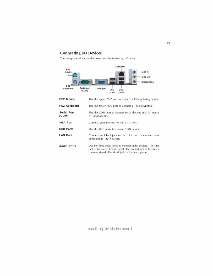
Connecting I/O DevicesThe backplane of the motherboard has the following I/O ports:
PS2 Mouse Use the upper PS/2 port to connect a PS/2 pointing device.
PS2 Keyboard Use the lower PS/2 port to connect a PS/2 keyboard.
Serial Port Use the COM port to connect serial devices such as mouse(COM) or fax/modems.
VGA Port Connect your monitor to the VGA port.
LAN Port Connect an RJ-45 jack to the LAN port to connect yourcomputer to the Network.
USB Ports Use the USB ports to connect USB devices.
Audio Ports Use the three audio jacks to connect audio devices. The firstjack is for stereo line-in signal. The second jack is for stereoline-out signal. The third jack is for microphone.
22
Installing the Motherboard
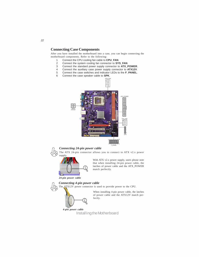
Connecting Case Components
1 Connect the CPU cooling fan cable to CPU_FAN.2 Connect the system cooling fan connector to SYS_FAN.3 Connect the standard power supply connector to ATX_POWER.4 Connect the auxiliary case power supply connector to ATX12V.5 Connect the case switches and indicator LEDs to the F_PANEL.6 Connect the case speaker cable to SPK.
The ATX 24-pin connector allows you to connect to ATX v2.x powersupply.
With ATX v2.x power supply, users please notethat when installing 24-pin power cable, thelatches of power cable and the ATX_POWERmatch perfectly.
Connecting 24-pin power cable
24-pin power cable
The ATX12V power connector is used to provide power to the CPU.
When installing 4-pin power cable, the latchesof power cable and the ATX12V match per-fectly.
Connecting 4-pin power cable
After you have installed the motherboard into a case, you can begin connecting themotherboard components. Refer to the following:
4-pin power cable

23
Installing the Motherboard
ATX12V: ATX 12V Power Connector
Users please note that the fan connector supports the CPU cooling fan of1.1A ~ 2.2A (26.4W max) at +12V.
ATX_POWER: ATX 24-pin Power Connector
Pin Signal Name Pin Signal Name1 +3.3V 13 +3.3V2 +3.3V 14 -12V3 Ground 15 Ground4 +5V 16 PS_ON5 Ground 17 Ground6 +5V 18 Ground7 Ground 19 Ground8 PWRGD 20 -5V9 +5VSB 21 +5V
10 +12V 22 +5V11 +12V 23 +5V12 +3.3V 24 Ground
SYS_FAN: System Cooling FAN Power Connector
Pin Signal Name Function1 GND System Ground2 +12V Power +12V3 Sense Sensor
CPU_FAN: FAN Power Connector
Pin Signal Name
4 +12V3 +12V2 Ground1 Ground
1 GND System Ground
3 Sense Sensor4 Control CPU FAN control
Pin Signal Name Function
2 +12V Power +12V

24
Installing the Motherboard
4 Speaker Signal3 GND2 NC1 +5V
Pin Signal Name
SPK: Internal speaker header
Front Panel HeaderThe front panel header (F_PANEL ) provides a standard set of switch and LEDheaders commonly found on ATX or Micro ATX cases. Refer to the table below forinformation:
Reset SwitchSupporting the reset function requires connecting pin 5 and 7 to a momentary-contact switch that is normally open. When the switch is closed, the board resets andruns POST.
Power/Sleep/Message waiting LED
Connecting pins 2 and 4 to a single or dual-color, front panel mounted LED providespower on/off, sleep, and message waiting indication.
Hard Drive Activity LED
Connecting pins 1 and 3 to a front panel mounted LED provides visual indicationthat data is being read from or written to the hard drive. For the LED to functionproperly, an IDE drive should be connected to the onboard IDE interface. The LEDwill also show activity for devices connected to the SCSI (hard drive activity LED)connector.
Pin Signal Function Pin Signal Function1 HD_LED_P Hard disk LED (+) 2 FP PWR/SLP *MSG LED (+)
3 HD_LED_N Hard disk LED (-)5 RST_SW_N Reset Switch (-)7 RST_SW_P Reset Switch (+)9 RSVD Reserved
4 FP PWR/SLP *MSG LED (-)6 PWR_SW_P Power Switch (+)8 PWR_SW_N Power Switch (-)
10 Key No pin* MSG LED (dual color or single color)

25
Installing the Motherboard
Power SwitchSupporting the power on/off function requires connecting pins 6 and 8 to a momen-tary-contact switch that is normally open. The switch should maintain contact for atleast 50 ms to signal the power supply to switch on or off. The time requirement isdue to internal de-bounce circuitry. After receiving a power on/off signal, at least twoseconds elapses before the power supply recognizes another on/off signal.
This concludes Chapter 2. The next chapter covers the BIOS.

26
Installing the Motherboard
Memo

27
Introducing the Motherboard
Chapter 3Using BIOS
About the Setup UtilityThe computer uses the latest “American Megatrends Inc.” BIOS with support forWindows Plug and Play. The CMOS chip on the motherboard contains the ROMsetup instructions for configuring the motherboard BIOS.
The BIOS (Basic Input and Output System) Setup Utility displays the system’sconfiguration status and provides you with options to set system parameters. Theparameters are stored in battery-backed-up CMOS RAM that saves this informationwhen the power is turned off. When the system is turned back on, the system isconfigured with the values you stored in CMOS.
The BIOS Setup Utility enables you to configure:
• Hard drives, diskette drives and peripherals• Video display type and display options• Password protection from unauthorized use• Power Management features
The settings made in the Setup Utility affect how the computer performs. Beforeusing the Setup Utility, ensure that you understand the Setup Utility options.
This chapter provides explanations for Setup Utility options.
The Standard ConfigurationA standard configuration has already been set in the Setup Utility. However, werecommend that you read this chapter in case you need to make any changes in thefuture.
This Setup Utility should be used:• when changing the system configuration• when a configuration error is detected and you are prompted to make
changes to the Setup Utility• when trying to resolve IRQ conflicts• when making changes to the Power Management configuration• when changing the password or making other changes to the Security
Setup
Entering the Setup UtilityWhen you power on the system, BIOS enters the Power-On Self Test (POST)routines. POST is a series of built-in diagnostics performed by the BIOS. After thePOST routines are completed, the following message appears:
Press DEL to enter SETUP

28
Introducing the Motherboard
BIOS Navigation KeysThe BIOS navigation keys are listed below:
Press the delete key to access the BIOS Setup Utility.
KEY FUNCTION
Scrolls through the items on a menu+/-/PU/PD Modifies the selected field’s values
F10 Saves the current configuration and exits setup
F1 Displays a screen that describes all key functions
F9 Loads an optimized setting for better performance
ESC Exits the current menu
Using BIOSWhen you start the Setup Utility, the main menu appears. The main menu of theSetup Utility displays a list of the options that are available. A highlight indicateswhich option is currently selected. Use the cursor arrow keys to move the highlightto other options. When an option is highlighted, execute the option by pressing<Enter>.
Some options lead to pop-up dialog boxes that prompt you to verify that you wish toexecute that option. Other options lead to dialog boxes that prompt you for infor-mation.
Some options (marked with a triangle ) lead to submenus that enable you to changethe values for the option. Use the cursor arrow keys to scroll through the items in thesubmenu.
In this manual, default values are enclosed in parenthesis. Submenu items are denotedby a triangle .
Enter Select
CMOS Setup Utility -- Copyright (C) 1985-2007, American Megatrends, Inc.
v02.61 (C)Copyright 1985-2007, American Mega trends, Inc.
: Move F10: Save ESC: Exit+/-/: ValueEnter : SelectF9: Optimized Defaults F1:General Help
Standard CMOS SetupAdvanced SetupAdvanced Chipset SetupIntegrated PeripheralsPower Management SetupPCI/PnP SetupPC Health Status
Frequency/Voltage ControlLoad Default SettingsSupervisor PasswordUser PasswordSave & Exit SetupExit Without Saving
The default BIOS setting for this motherboard applies for most conditionswith optimum performance. It is not suggested to change the default values inthe BIOS setup and the manufacture takes no responsibility to any damagecaused by changing the BIOS settings.
29
Introducing the Motherboard
For the purpose of better product maintenance, the manufacture reservesthe right to change the BIOS items presented in this manual. The BIOS setupscreens shown in this chapter are for reference only and may differ from theactual BIOS. Please visit the manufacture’s website for updated manual.
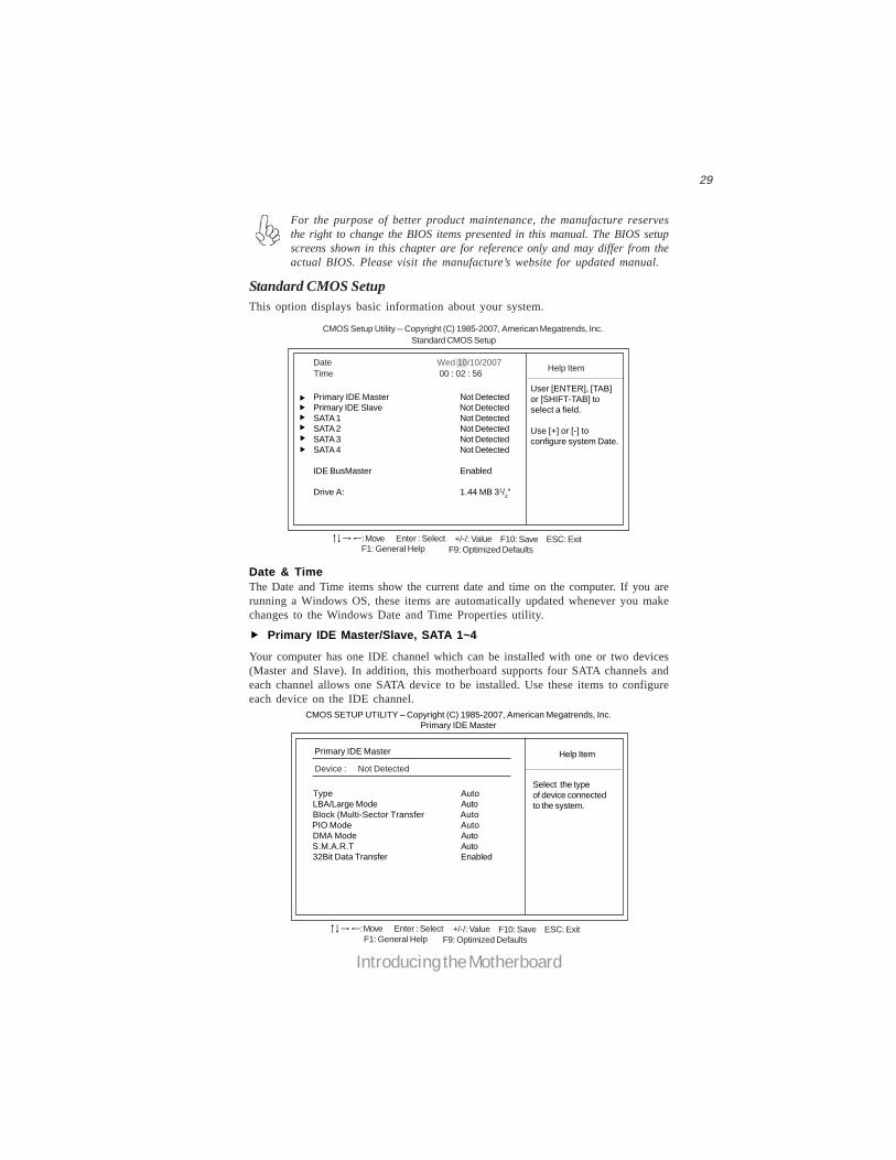
Standard CMOS SetupThis option displays basic information about your system.
Date Wed 10/10/2007
Primary IDE Master Not DetectedPrimary IDE Slave Not DetectedSATA 1 Not DetectedSATA 2 Not DetectedSATA 3 Not DetectedSATA 4 Not Detected
IDE BusMaster Enabled
Drive A: 1.44 MB 31/2”
Help Item
CMOS Setup Utility -- Copyright (C) 1985-2007, American Megatrends, Inc.
Time 00 : 02 : 56
User [ENTER], [TAB]or [SHIFT-TAB] toselect a field.
Use [+] or [-] toconfigure system Date.
Standard CMOS Setup
: Move F10: Save ESC: ExitEnter : Select +/-/: ValueF9: Optimized DefaultsF1: General Help
Date & TimeThe Date and Time items show the current date and time on the computer. If you arerunning a Windows OS, these items are automatically updated whenever you makechanges to the Windows Date and Time Properties utility.
Primary IDE Master/Slave, SATA 1~4
Your computer has one IDE channel which can be installed with one or two devices(Master and Slave). In addition, this motherboard supports four SATA channels andeach channel allows one SATA device to be installed. Use these items to configureeach device on the IDE channel.
CMOS SETUP UTILITY – Copyright (C) 1985-2007, American Megatrends, Inc.Primary IDE Master
Primary IDE Master
Type AutoLBA/Large Mode AutoBlock (Multi-Sector Transfer Auto
PIO Mode AutoDMA Mode Auto
S.M.A.R.T Auto32Bit Data Transfer Enabled
Help Item
Select the typeof device connectedto the system.
Device : Not Detected
: Move F10: Save ESC: ExitEnter : Select +/-/: ValueF9: Optimized DefaultsF1: General Help

30
Introducing the Motherboard
LBA/Large Mode (Auto)Use this item to set the LAB/Large mode to enhance hard disk performance byoptimizing the area the hard disk is visited each time.Block (Multi-Sector Transfer) (Auto)If the feature is enabled, it will enhance hard disk performance by reading or writingmore data during each transfer.PIO Mode (Auto)Use this item to set the PIO mode to enhance hard disk performance by optimizingthe hard disk timing.DMA Mode (Auto)DMA capability allows user to improve the transfer-speed and data-integrity forcompatible IDE devices.S.M.A.R.T. (Auto)The S.M.A.R.T. (Self-Monitoring, Analysis and Reporting Technology) system is adiagnostics technology that monitors and predicts device performance. S.M.A.R.T.software resides on both the disk drive and the host computer.
32Bit Data Transfer (Enabled)Use this item to set the onboard SATA-IDE channel to be disabled, IDE, or RAID.
Press <Esc> to return to the Standard CMOS Setup page.
Type (Auto)Use this item to configure the type of the IDE device that you specify. If the featureis enabled, it will enhance hard disk performance by reading or writing more dataduring each transfer.
IDE BusMaster (Enabled)This item enables or disables the DMA under DOS mode. We recommend you to leavethis item at the default value.
Drive A (1..44 MB 31/2”)This item defines the characteristics of any diskette drive attached to the system.You can connect one or two diskette drives.
Press <Esc> to return to the main menu setting page.
31
Introducing the Motherboard
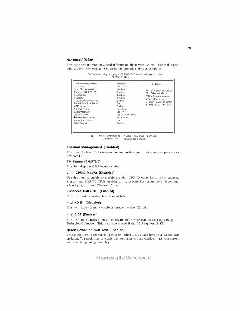
Advanced SetupThis page sets up more advanced information about your system. Handle this pagewith caution. Any changes can affect the operation of your computer.
CMOS Setup Utility - Copyright (C) 1985-2007, American Megatrends, Inc. Advanced Setup
Thermal Management EnabledTM Status TM1/TM2Limit CPUID MaxVal DisabledEnhanced Halt (C1E) EnabledIntel XD Bit DisabledIntel EIST EnabledQuick Power on Self Test EnabledBoot Up Numlock Status OnAPIC Mode Enabled1st Boot Device Hard Drive2nd Boot Device CD/DVD3rd Boot Device 1st FLOPPY DRIVE Removable Drives Press EnterBoot Other Device YesBIOS Protect Disabled
For the processoritesCPUID belows 0F41h.TM2 only can be enableunder below setting.1. Freq.>=3.6GHz FSB8002. Freq.>=2.8GHz FSB533
Help Item
F10: Save ESC: Exit+/-/: ValueEnter : SelectF9: Optimized DefaultsF1:General Help
: Move
Thermal Management (Enabled)
Quick Power on Self Test (Enabled)Enable this item to shorten the power on testing (POST) and have your system startup faster. You might like to enable this item after you are confident that your systemhardware is operating smoothly.
Limit CPUID MaxVal (Disabled)
Enhanced Halt (C1E) (Enabled)
Intel XD Bit (Disabled)
Intel EIST (Enabled)
Use this item to enable or disable the Max CPU ID value limit. When supportsPrescott and LGA775 CPUs, enables this to prevent the system from “rebooting”when trying to install Windows NT 4.0.
This item enables or disables enhanced halt.
This item displays CPU’s temperature and enables you to set a safe temperature toPrescott CPU.
TM Status (TM1/TM2)This item displays CPU Monitor status.
This item allows users to enable or disable the Intel XD bit.
This item allows users to enbale or disable the EIST(Enhanced Intel SpeedStepTechnology) function. This item shows only if the CPU supports EIST.
32
Introducing the Motherboard
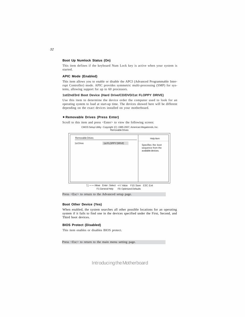
1st/2nd/3rd Boot Device (Hard Drive/CD/DVD/1st FLOPPY DRIVE)Use this item to determine the device order the computer used to look for anoperating system to load at start-up time. The devices showed here will be differentdepending on the exact devices installed on your motherboard.
APIC Mode (Enabled)This item allows you to enable or disable the APCI (Advanced Programmable Inter-rupt Controller) mode. APIC provides symmetric multi-processing (SMP) for sys-tems, allowing support for up to 60 processors.
Boot Up Numlock Status (On)This item defines if the keyboard Num Lock key is active when your system isstarted.
Removable Drives (Press Enter)Scroll to this item and press <Enter> to view the following screen:
Removable Drives
1st Drive 1st FLOPPY DRIVE
Help Item
Specifies the bootsequence from theavailable devices.
F10: Save ESC: Exit+/-/: ValueEnter : SelectF9: Optimized DefaultsF1:General Help
: Move
CMOS Setup Utility - Copyright (C) 1985-2007, American Megatrends, Inc.Removable Drives
Press <Esc> to return to the Advanced setup page.
Press <Esc> to return to the main menu setting page.
Boot Other Device (Yes)When enabled, the system searches all other possible locations for an operatingsystem if it fails to find one in the devices specified under the First, Second, andThird boot devices.
BIOS Protect (Disabled)This item enables or disables BIOS protect.
33
Introducing the Motherboard
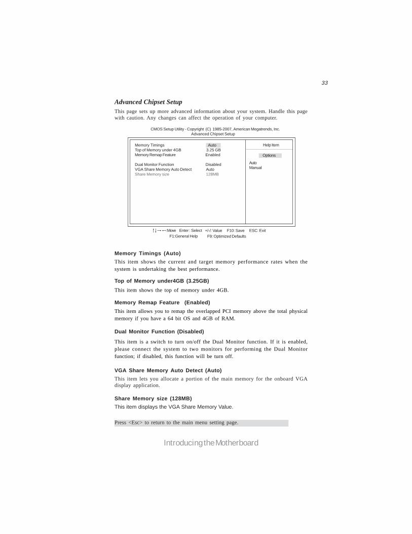
Advanced Chipset SetupThis page sets up more advanced information about your system. Handle this pagewith caution. Any changes can affect the operation of your computer.
CMOS Setup Utility - Copyright (C) 1985-2007, American Megatrends, Inc. Advanced Chipset Setup
Memory Timings AutoTop of Memory under 4GB 3.25 GBMemory Remap Feature Enabled
Dual Monitor Function DisabledVGA Share Memory Auto Detect AutoShare Memory size 128MB
Help Item
F10: Save ESC: Exit+/-/: ValueEnter : SelectF9: Optimized DefaultsF1:General Help
: Move
AutoManual
Options
Memory Timings (Auto)
Top of Memory under4GB (3.25GB)
Memory Remap Feature (Enabled)
Dual Monitor Function (Disabled)
VGA Share Memory Auto Detect (Auto)This item lets you allocate a portion of the main memory for the onboard VGAdisplay application.
Share Memory size (128MB)This item displays the VGA Share Memory Value.
Press <Esc> to return to the main menu setting page.
This item is a switch to turn on/off the Dual Monitor function. If it is enabled,please connect the system to two monitors for performing the Dual Monitorfunction; if disabled, this function will be turn off.
This item shows the current and target memory performance rates when thesystem is undertaking the best performance.
This item shows the top of memory under 4GB.
This item allows you to remap the overlapped PCI memory above the total physicalmemory if you have a 64 bit OS and 4GB of RAM.
34
Introducing the Motherboard
Onboard LAN Function (Enabled)Use this item to enable or disable the onboard LAN function.Onboard LAN Boot ROM (Disabled)Use this item to enable or disable the booting from the onboard LAN or a networkadd-in card with a remote boot ROM installed.
Onboard AUDIO Function (Enabled)Use this item to enable or disable the onboard audio device.
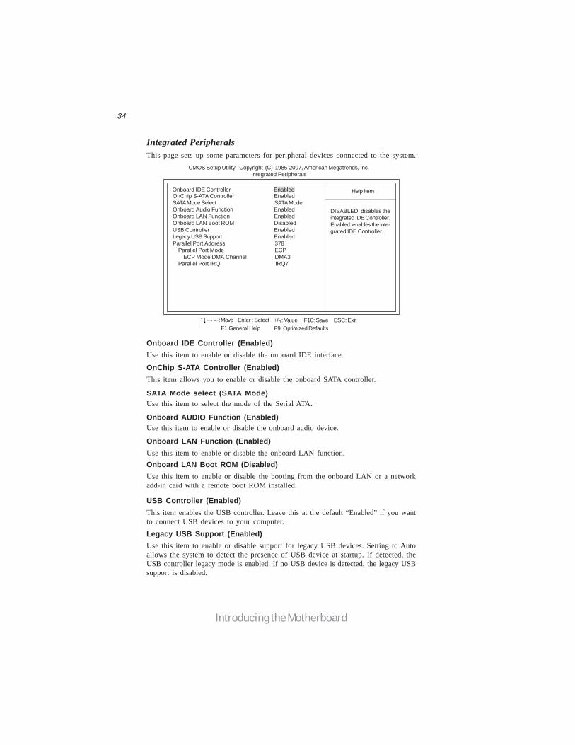
Integrated PeripheralsThis page sets up some parameters for peripheral devices connected to the system.
CMOS Setup Utility - Copyright (C) 1985-2007, American Megatrends, Inc. Integrated Peripherals
Onboard IDE Controller Enabled Help Item
F10: Save ESC: Exit+/-/: ValueEnter : SelectF9: Optimized DefaultsF1:General Help
: Move
OnChip S-ATA Controller EnabledSATA Mode Select SATA ModeOnboard Audio Function EnabledOnboard LAN Function EnabledOnboard LAN Boot ROM DisabledUSB Controller EnabledLegacy USB Support EnabledParallel Port Address 378 Parallel Port Mode ECP ECP Mode DMA Channel DMA3 Parallel Port IRQ IRQ7
DISABLED: disables theintegrated IDE Controller.Enabled: enables the inte-grated IDE Controller.
SATA Mode select (SATA Mode)Use this item to select the mode of the Serial ATA.
Onboard IDE Controller (Enabled)Use this item to enable or disable the onboard IDE interface.
OnChip S-ATA Controller (Enabled)This item allows you to enable or disable the onboard SATA controller.
Legacy USB Support (Enabled)Use this item to enable or disable support for legacy USB devices. Setting to Autoallows the system to detect the presence of USB device at startup. If detected, theUSB controller legacy mode is enabled. If no USB device is detected, the legacy USBsupport is disabled.
USB Controller (Enabled)This item enables the USB controller. Leave this at the default “Enabled” if you wantto connect USB devices to your computer.

35
Introducing the Motherboard
Power Management SetupThis page sets up some parameters for system power management operation.
Select the ACPI stateused for System Sus-pend.
Help Item
CMOS Setup Utility - Copyright (C) 1985-2007, American Megatrends, Inc. Power Management Setup
ACPI Suspend Type S3 (STR)Soft-off by PWR-BTTN Instant OffPWRON After PWR-Fail Power OffResume By PCI/PCI-E/Lan PME DisabledResume By USB (S3) DisabledResume By PS2 KB (S3) DisabledResume By PS2 MS (S3) DisabledResume On Ring DisabledResume on RTC Alarm Disabled
F10: Save ESC: Exit+/-/: ValueEnter : SelectF9: Optimized DefaultsF1:General Help
: Move
Parallel Port IRQ (IRQ7)
ECP Mode DMA Channel (DMA3)
Parallel Port Mode (ECP)Use this item to set the parallel port mode. You can select Normal (Standard ParallelPort), ECP (Extended Capabilities Port), EPP (Enhanced Parallel Port), or EPP &ECP.
Use this item to assign the DMA Channel under ECP Mode function.
Use this item to assign IRQ to the parallel port.
Press <Esc> to return to the main menu setting page.
Parallel Port Address (378)Use this item to enable or disable the onboard Parallel port, and to assign a portaddress.
ACPI Suspend Type (S3(STR))Use this item to define how your system suspends. In the default, S3, the suspendmode is a suspend to RAM, i.e, the system shuts down with the exception of a refreshcurrent to the system memory.

36
Introducing the Motherboard
Soft-Off By PWR-BTTN (Instant Off)Under ACPI (Advanced Configuration and Power management Interface) you cancreate a software power down. In a software power down, the system can be resumedby Wake Up Alarms. This item lets you install a software power down that is con-trolled by the power button on your system. If the item is set to Instant-Off, then thepower button causes a software power down. If the item is set to Delay 4 Sec, thenyou have to hold the power button down for four seconds to cause a software powerdown.
Resume by PCI/PCI-E/Lan PME (Disabled)These items specify whether the system will be awakened from power saving modeswhen activity or input signal of the specified hardware peripheral or component isdetected.Resume By USB (S3) (Disabled)This item allows you to enable/disable the USB device wakeup function from S3/S4mode.
Resume By PS2 KB (S3) (Disabled)This item enable or disable you to allow keyboard activity to awaken the systemfrom power saving mode.Resume By PS2 MS (S3) (Disabled)This item enable or disable you to allow mouse activity to awaken the system frompower saving mode.
PWRON After PWR-Fail (Power Off)
Resume On Ring (Disabled)
This item enables your computer to automatically restart or return to its last oper-ating status.
The system can be turned off with a software command. If you enable this item, thesystem can automatically resume if there is an incoming call on the Modem/Ring, ortraffic on the netwwork adapter. You must use an ATX power supply in order to usethis feature.
Press <Esc> to return to the main menu setting page.
Resume By RTC Alarm (Disabled)The system can be turned off with a software command. If you enable this item, thesystem can automatically resume at a fixed time based on the system’s RTC (realtimeclock). Use the items below this one to set the date and time of the wake-up alarm.You must use an ATX power supply in order to use this feature.
37
Introducing the Motherboard
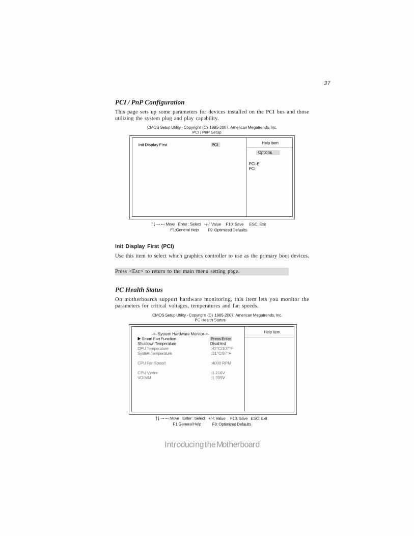
Init Display First (PCI)Use this item to select which graphics controller to use as the primary boot devices.
PCI / PnP ConfigurationThis page sets up some parameters for devices installed on the PCI bus and thoseutilizing the system plug and play capability.
Help ItemInit Display First PCI
CMOS Setup Utility - Copyright (C) 1985-2007, American Megatrends, Inc. PCI / PnP Setup
F10: Save ESC: Exit+/-/: ValueEnter : SelectF9: Optimized DefaultsF1:General Help
: Move
PCI-EPCI
PC Health StatusOn motherboards support hardware monitoring, this item lets you monitor theparameters for critical voltages, temperatures and fan speeds.
-=- System Hardware Monitor-=- Smart Fan Function Press EnterShutdown Temperature DisabledCPU Temperature :42°C/107°FSystem Temperature :31°C/87°F
CPU Fan Speed :4000 RPM
CPU Vcore :1.216VVDIMM :1.905V
Help Item
CMOS Setup Utility - Copyright (C) 1985-2007, American Megatrends, Inc. PC Health Status
F10: Save ESC: Exit+/-/: ValueEnter : SelectF9: Optimized DefaultsF1:General Help
: Move
Options
Press <Esc> to return to the main menu setting page.
38
Introducing the Motherboard
CMOS Setup Utility - Copyright (C) 1985-2007, American Megatrends, Inc. Smart Fan Function
Help Item
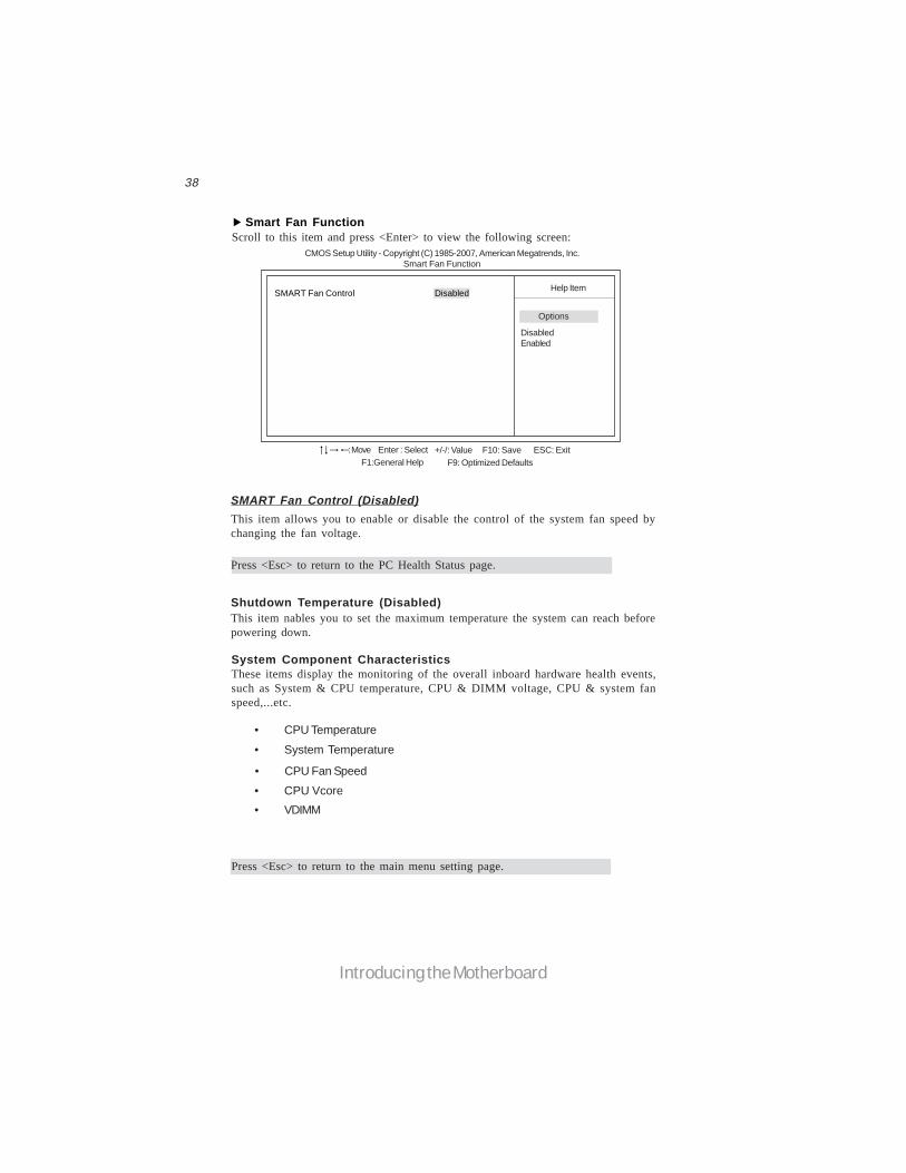
Smart Fan FunctionScroll to this item and press <Enter> to view the following screen:
DisabledEnabled
Options
SMART Fan Control Disabled
SMART Fan Control (Disabled)This item allows you to enable or disable the control of the system fan speed bychanging the fan voltage.
Shutdown Temperature (Disabled)This item nables you to set the maximum temperature the system can reach beforepowering down.
System Component CharacteristicsThese items display the monitoring of the overall inboard hardware health events,such as System & CPU temperature, CPU & DIMM voltage, CPU & system fanspeed,...etc.
• CPU Fan Speed
• CPU Temperature
• System Temperature
• VDIMM • CPU Vcore
Press <Esc> to return to the main menu setting page.
F10: Save ESC: Exit+/-/: ValueEnter : SelectF9: Optimized DefaultsF1:General Help
: Move
Press <Esc> to return to the PC Health Status page.

39
Introducing the Motherboard
Frequency/Voltage ControlThis page enables you to set the clock speed and system bus for your system. Theclock speed and system bus are determined by the kind of processor you have in-stalled in your system.
CMOS Setup Utility - Copyright (C) 1985-2007, American Megatrends, Inc. Frequency/Voltage Control
Help Item
F10: Save ESC: Exit+/-/: ValueEnter : SelectF9: Optimized DefaultsF1:General Help
: Move
Auto Detect DIMM/PCI CIK EnabledCPU BSEL Select AutoPCIE Spread Spectrum DisabledCPU Spread Spectrum DisabledSystem Clock Mode AutoMemory Voltage +1.90VNB Voltage 1.349V
Auto Detect DIMM/PCI Clk (Enabled)When this item is enabled, BIOS will disable the clock signal of free DIMM/PCI slots.
CPU BSEL Select (Auto)These items is used to select the CPU/LDT BSEL.
Manufacturer: IntelRatio Status: Unlocked (Min:06, Max:12)Ratio Autual Value: 12
Manufacturer (Intel)
These items show the brand of the CPU installed in your system.
Ratio Status/Ratio Actual ValueThese items show the Locked ratio status and the actual ratio of the CPU installed inyour system.
Memory Voltage (+1.90V)This item allows users to adjust the DDR memory voltage.
PCIE Spread Spectrum (Disabled)This item, when enabled, can significantly reduce the EMI (Electromagnetic Inter-ference) generated by the PCIE.
[Auto] Set FSB & Memoryclock automatically.
[Linked] Allows Memoryand FSB to overclock pro-portionally.
[Manual] Enter FSB andMemory clock manually.
CPU Spread Spectrum (Disabled)If you enable spread spectrum, it can significantly reduce the EMI (Electro-MagneticInterference) generated by the system.
System Clock Mode (Auto)This item determines the current and target FSB and memory speed when thesystem is undertaking the best performance.

40
Introducing the Motherboard
Change Supervisor Password (Press Enter)You can select this option and press <Enter> to access the sub menu. You can use thesub menu to change the supervisor password.
Load Default SettingsThis option opens a dialog box to ask if you are sure to install optimized defaults ornot. You select [OK], and then <Enter>, the Setup Utility loads all default values; orselect [Cancel], and then <Enter>, the Setup Utility does not load default values.
Press <Esc> to return to the main menu setting page.
Supervisor PasswordThis page helps you install or change a password.
CMOS Setup Utility - Copyright (C) 1985-2007, American Megatrends, Inc. Supervisor Password
Install or Change thepassword.
Help ItemSupervisor Password :Not Installed
Change Supervisor Password Press Enter
F10: Save ESC: Exit+/-/: ValueEnter : SelectF9: Optimized DefaultsF1:General Help
: Move
Supervisor Password (Not Installed)This item indicates whether a supervisor password has been set. If the password hasbeen installed, Installed displays. If not, Not Installed displays.
NB Voltage (1.349V)
Press <Esc> to return to the main menu setting page.
This item allows users to adjust the Northbridge voltage.
41
Introducing the Motherboard
Save & Exit SetupHighlight this item and press <Enter> to save the changes that you have made in theSetup Utility and exit the Setup Utility. When the Save and Exit dialog box appears,select [OK] to save and exit, or select [Cancel] to return to the main menu.
Exit Without SavingHighlight this item and press <Enter> to discard any changes that you have made inthe Setup Utility and exit the Setup Utility. When the Exit Without Saving dialogbox appears, select [OK] to discard changes and exit, or select [Cancel] to return tothe main menu.
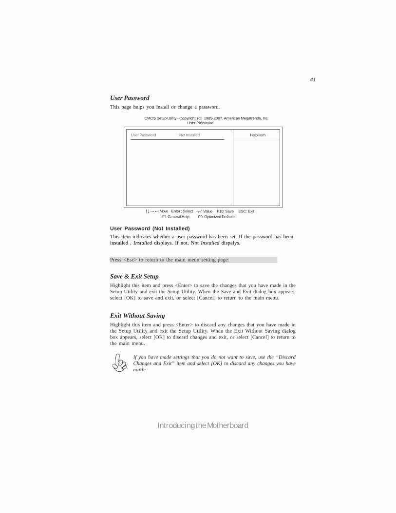
User PasswordThis page helps you install or change a password.
Help Item
CMOS Setup Utility - Copyright (C) 1985-2007, American Megatrends, Inc. User Password
Press <Esc> to return to the main menu setting page.
User Password : Not Installed
F10: Save ESC: Exit+/-/: ValueEnter : SelectF9: Optimized DefaultsF1:General Help
: Move
If you have made settings that you do not want to save, use the “DiscardChanges and Exit” item and select [OK] to discard any changes you havemade.
User Password (Not Installed)This item indicates whether a user password has been set. If the password has beeninstalled , Installed displays. If not, Not Installed dispalys.
42
Introducing the Motherboard
This concludes Chapter 3. Refer to the next chapter for information on the softwaresupplied with the motherboard.
Updating the BIOSYou can download and install updated BIOS for this motherboard from themanufacturer’s Web site. New BIOS provides support for new peripherals, improve-ments in performance, or fixes for known bugs. Install new BIOS as follows:
1 If your motherboard has a BIOS protection jumper, change the setting toallow BIOS flashing.
2 If your motherboard has an item called Firmware Write Protect in Ad-vanced BIOS features, disable it. (Firmware Write Protect preventsBIOS from being overwritten.)
3 Create a bootable system disk. (Refer to Windows online help forinformation on creating a bootable system disk.)
4 Download the Flash Utility and new BIOS file from the manufacturer’sWeb site. Copy these files to the system diskette you created in Step 3.
5 Turn off your computer and insert the system diskette in your computer’sdiskette drive. (You might need to run the Setup Utility and change theboot priority items on the Advanced BIOS Features Setup page, toforce your computer to boot from the floppy diskette drive first.)
6 At the A:\ prompt, type the Flash Utility program name and the file nameof the new bios and then press <Enter>. Example: AMINF340.EXE040706.ROM
7 When the installation is complete, remove the floppy diskette from thediskette drive and restart your computer. If your motherboard has aFlash BIOS jumper, reset the jumper to protect the newly installed BIOSfrom being overwritten. The computer will restart automatically.
43
Using the Motherboard Software
Chapter 4Using the Motherboard Software
Auto-installing under Windows XP/Vista
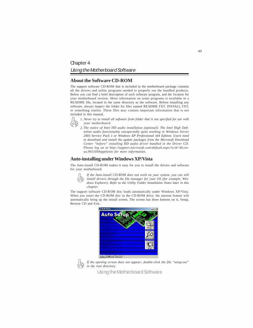
The support software CD-ROM disc loads automatically under Windows XP/Vista.When you insert the CD-ROM disc in the CD-ROM drive, the autorun feature willautomatically bring up the install screen. The screen has three buttons on it, Setup,Browse CD and Exit.
If the opening screen does not appear; double-click the file “setup.exe”in the root directory.
If the Auto-install CD-ROM does not work on your system, you can stillinstall drivers through the file manager for your OS (for example, Win-dows Explorer). Refer to the Utility Folder Installation Notes later in thischapter.
About the Software CD-ROMThe support software CD-ROM that is included in the motherboard package containsall the drivers and utility programs needed to properly run the bundled products.Below you can find a brief description of each software program, and the location foryour motherboard version. More information on some programs is available in aREADME file, located in the same directory as the software. Before installing anysoftware, always inspect the folder for files named README.TXT, INSTALL.TXT,or something similar. These files may contain important information that is notincluded in this manual.
Never try to install all software from folder that is not specified for use withyour motherboard.The notice of Intel HD audio installation (optional): The Intel High Defi-nition audio functionality unexpectedly quits working in Windows Server2003 Service Pack 1 or Windows XP Professional x64 Edition. Users needto download and install the update packages from the Microsoft DownloadCenter “before” installing HD audio driver bundled in the Driver CD.Please log on to http://support.microsoft.com/default.aspx?scid=kb;en-us;901105#appliesto for more information.
1.
2.
The Auto-install CD-ROM makes it easy for you to install the drivers and softwarefor your motherboard.
44
Using the Motherboard Software
Setup Tab
Setup Click the Setup button to run the software installation program.Select from the menu which software you want to install.
Browse CD The Browse CD button is the standard Windows command that al-lows you to open Windows Explorer and show the contents of thesupport CD.
Before installing the software from Windows Explorer, look for a filenamed README.TXT, INSTALL.TXT or something similar. Thisfile may contain important information to help you install the soft-ware correctly.
Some software is installed in separate folders for different operatingsystems, such as Windows XP/Vista. Always go to the correct folderfor the kind of OS you are using.
In install the software, execute a file named SETUP.EXE orINSTALL.EXE by double-clicking the file and then following theinstructions on the screen.
Exit The EXIT button closes the Auto Setup window.
Application TabLists the software utilities that are available on the CD.
Read Me TabDisplays the path for all software and drivers available on the CD.
Running SetupFollow these instructions to install device drivers and software for the motherboard:
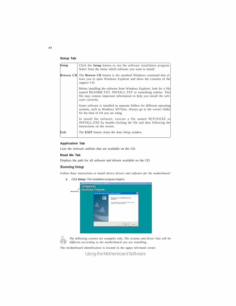
1. Click Setup. The installation program begins:
The following screens are examples only. The screens and driver lists will bedifferent according to the motherboard you are installing.
The motherboard identification is located in the upper left-hand corner.
45
Using the Motherboard Software
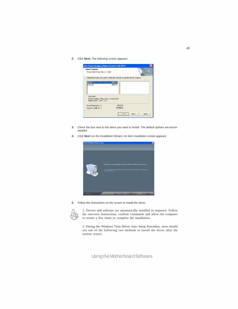
2. Click Next. The following screen appears:
3. Check the box next to the items you want to install. The default options are recom-mended.
4. Click Next run the Installation Wizard. An item installation screen appears:
5. Follow the instructions on the screen to install the items.
1. Drivers and software are automatically installed in sequence. Followthe onscreen instructions, confirm commands and allow the computerto restart a few times to complete the installation.
2. During the Windows Vista Driver Auto Setup Procedure, users shoulduse one of the following two methods to install the driver after thesystem restart.

46
Using the Motherboard Software
Method 1. Run Reboot Setup
Windows Vista will block startup programs by default when installing drivers after thesystem restart. You must select taskbar icon Run Blocked Program and run RebootSetup to install the next driver, until you finish all drivers installation.
Method 2. Disable UAC (User Account Control)* For administrator account only. Standard user account can only use Method 1.
Disable Vista UAC function before installing drivers, then use CD driver to installdrivers, it will continue to install drivers after system restart without running blockedprograms.
Follow these instructions to Disable Vista UAC function:
1. Go to Control Panel.
47
Using the Motherboard Software
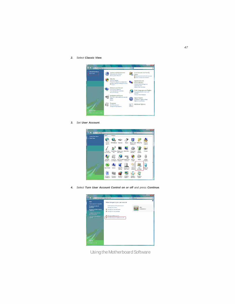
2. Select Classic View.
3. Set User Account.
4. Select Turn User Account Control on or off and press Continue.
48
Using the Motherboard Software
Manual InstallationInsert the CD in the CD-ROM drive and locate the PATH.DOC file in the rootdirectory. This file contains the information needed to locate the drivers for yourmotherboard.
Look for the chipset and motherboard model; then browse to the directory and pathto begin installing the drivers. Most drivers have a setup program (SETUP.EXE) thatautomatically detects your operating system before installation. Other drivers havethe setup program located in the operating system subfolder.
If the driver you want to install does not have a setup program, browse to theoperating system subfolder and locate the readme text file (README.TXT orREADME.DOC) for information on installing the driver or software for your oper-ating system.
Utility Software ReferenceAll the utility software available from this page is Windows compliant. They areprovided only for the convenience of the customer. The following software is fur-nished under license and may only be used or copied in accordance with the terms ofthe license.
These software(s) are subject to change at anytime without prior notice.Please refer to the support CD for available software.
This concludes Chapter 4.
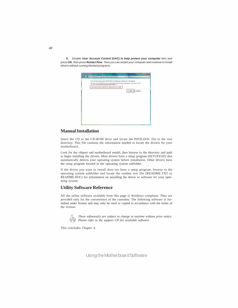
5. Disable User Account Control (UAC) to help protect your computer item andpress OK, then press Restart Now. Then you can restart your computer and continue to installdrivers without running blocked programs.

49
NVIDIA RAID Configuration
Chapter 5Setting Up NVIDIA RAID Configuration
Setting Up a Non-Bootable RAID Array
Setting Up the BIOS
Use the arrow keys to select Integrated Peripherals (see Figure 1.1), thenpress Enter.
The Integrated Peripherals window appears.
Figure 1.2 Integrated Peripherals Window
Figure 1.1 BIOS CMOS Setup Utility Main Window
Start your computer, then press Delete to enter the BIOS setup.The BIOS CMOS Setup Utility window appears.
1
2
There are two ways to setup NVIDIA RAID Configuration: one is to create a RAID1 Array for backup or a RAID 0 Array for increased performance just by addingadditional disk array without changing the original OS (Non-Bootable RAID Array);while the other is to configure the RAID Array disks when reinstalling the OS(Bootable RAID Array).
RAID arrays can be created/deleted using both MediaShield RAID BIOS and theMediaShield RAID Manager from Windows. This section only covers basic BIOSsetup required for non-bootable array. See the section "Setting Up a Bootable RAIDArray” for instructions on configuring the RAID array in BIOS. See sections on usingthe MediaShield RAID Manager for details on configuring non-bootable RAID fromWindows.

50
NVIDIA RAID Configuration
From the Integrated Peripherals Window, globally set SATA Mode select toRAID Mode (see Figure 1.2).
Press F10 to save the configuration and exit (F10 is the navigation key to
Installing the NVIDIA RAID Software Under WindowsThis section describes how to run the setup application and install the RAID soft-ware.
Start the nForce Setup program to open the NVIDIA Windows nForceDrivers page.
Figure 1.3 nForce Driver Installation Window
3
4
1
save the current configuration and exit setup in BIOS setting).
The PC reboots.
Make sure that the “NVIDIA IDE Driver” is selected.2 Select the modules that you want to install.
You must install the NVIDIA IDE driver in order to enable NVIDIA RAID.If you do not install the NVIDIA IDE driver, NVIDIA RAID will not beenabled.
Click Next and then follow the instructions.After the installation is com-pleted, be sure to reboot the PC.
After the reboot, initialize the newly created array.
3
4
5

51
NVIDIA RAID Configuration
Setting Up a Bootable RAID ArrayThis section explains how to configure a bootable NVIDIA RAID array.
Setting Up the BIOS
Use the arrow keys to select Integrated Peripherals (see Figure 1.4), thenpress Enter.
The Integrated Peripherals screen (or a screen similar to it) appears.
Figure 1.5 Integrated Peripherals Screen
From the Integrated Peripherals Window, globally set SATA Mode select toRAID Mode (see Figure 1.5).
Start your computer, then press Delete to enter the BIOS setup.The BIOS CMOS Setup Utility screen appears.
Figure 1.4 BIOS CMOS Setup Utility Main Screen
1
2
3
52
NVIDIA RAID Configuration
Configuring the NVIDIA RAID BIOSThe NVIDIA RAID BIOS set up lets you choose the RAID type and which hard drivesyou want to make part of the array.
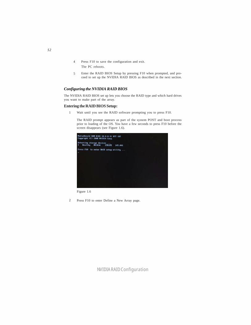
Entering the RAID BIOS Setup:1 Wait until you see the RAID software prompting you to press F10.
The RAID prompt appears as part of the system POST and boot processprior to loading of the OS. You have a few seconds to press F10 before thescreen disappears (see Figure 1.6).
Figure 1.6
Press F10 to enter Define a New Array page.2
5 Enter the RAID BIOS Setup by pressing F10 when prompted, and pro-ceed to set up the NVIDIA RAID BIOS as described in the next section.
The PC reboots.Press F10 to save the configuration and exit.4

53
NVIDIA RAID Configuration
The NVIDIA RAID Utility—Define a New Array screen appears (Figure1.7).
Figure 1.7 MediaShield BIOS
By default, RAID Mode is set to Mirroring and Striping Block is set to Optimal.
Using the Define a New Array ScreenIf necessary, press the tab key to move from field to field until the appropriate fieldis highlighted.
• Selecting the RAID Mode
Striping block size is given in kilobytes, and affects how data is arranged onthe disk. It is recommended to leave this value at the default Optimal, whichis 64KB, but the values can be between 4 KB and 128 KB (4, 8, 16, 32, 64,and 128 KB)
Assigning the DisksThe disks that you enabled from the RAID Config BIOS setup page appear in the FreeDisks block. These are the drives that are available for use as RAID array disks.
To designate a free disk to be used as a RAID array disk,
By default, this is set to Mirroring. To change to a different RAID mode,press the down arrow key until the mode that you want appears in the RAIDMode box—either Mirroring, Striping, Spanning, Stripe Mirroring or RAID5.
• Selecting the Striping Block Size
Note: Not all RAID levels are supported on all platforms. And enough Harddisks are required to complete the RAID configuration.
1 Tab to the Free Disks section.The first disk in the list is selectedMove it from the Free Disks block to the Array Disks block by pressing theright-arrow key (—>).
2
The first disk in the list is moved, and the next disk in the list is selected andready to be moved.
3 Continue pressing the right-arrow key (—>) until all the disks that you wantto use as RAID array disks appear in the Array Disks block.
54
NVIDIA RAID Configuration
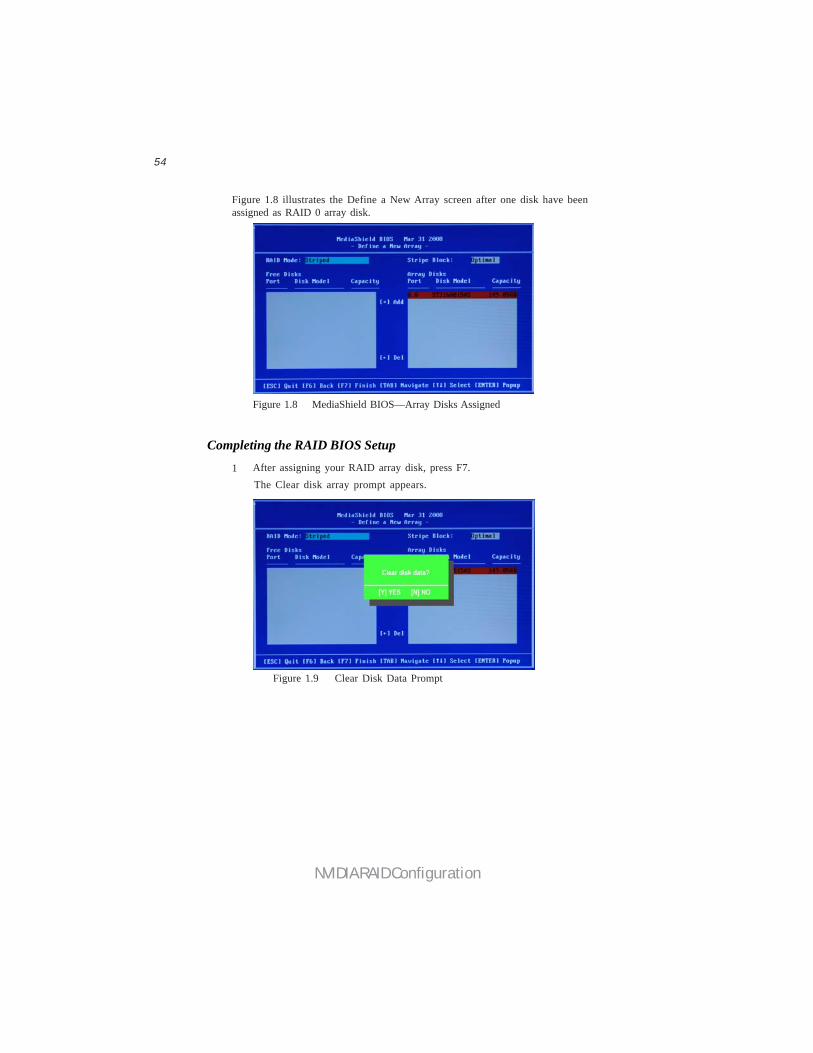
Figure 1.8 illustrates the Define a New Array screen after one disk have beenassigned as RAID 0 array disk.
Figure 1.8 MediaShield BIOS—Array Disks Assigned
Completing the RAID BIOS Setup
Figure 1.9 Clear Disk Data Prompt
After assigning your RAID array disk, press F7.The Clear disk array prompt appears.
1

55
NVIDIA RAID Configuration
Figure 1.10 Array List Window
Press Y to clear the disk data.The Array List screen appears, where you can review the RAID arrays thatyou have set up.
The Array Detail screen shows various information about the array that youselected, such as Striping Block used, RAID Mode, Striping Width, DiskModel Name, and disk capacity.
If you want to mark this disk as empty and wipe out all its contents, press C.
At the prompt, press Y to wipe out all the data, otherwise press N.
Press Enter again to go back to the previous screen and then press F10 to exitthe RAID setup.
3 Use the arrow keys to select the array that you want to set up, then press Bto specify the array as bootable.
Press Enter to view and verify details.
5
6
7
4
2

56
NVIDIA RAID Configuration
1 Copy all files in "…\IDE\WinXP\sataraid" to a floppy disk. (For Windows2000, substitute "Win2K" in the path.)
After you complete the RAID BIOS setup, boot from the Windows CD.
Figure 1.11 Windows Setup—Specify Devices
Installing the RAID DriversYour system may come with a Windows install CD that already includes NVIDIARAID drivers. If so, then this section is not relevant.
If that is not the case (or you are trying to install a new version of Windows), thenyou will need an NVIDIA RAID driver F6 install floppy. Check to see if one camewith your system. If not, you can create one by downloading the appropriate driverpackage and following the steps in this section.
Press F6 and wait a few moments for the Windows Setup screen toappear.
The Windows Setup program starts.
a Insert the floppy that has the RAID driver, press S, then press Enter.
Figure 1.12 Windows Setup—Selected SCSI Adapter
Specify the NVIDIA drivers.
The following Windows Setup screen appears:
2
3
4
57
NVIDIA RAID Configuration
b Select “NVIDIA RAID CLASS DRIVER (required)” and then press Enter.
c Press S again at the Specify Devices screen, then press Enter.
d Select “NVIDIA NForce Storage Controller (required)” and then press Enter.
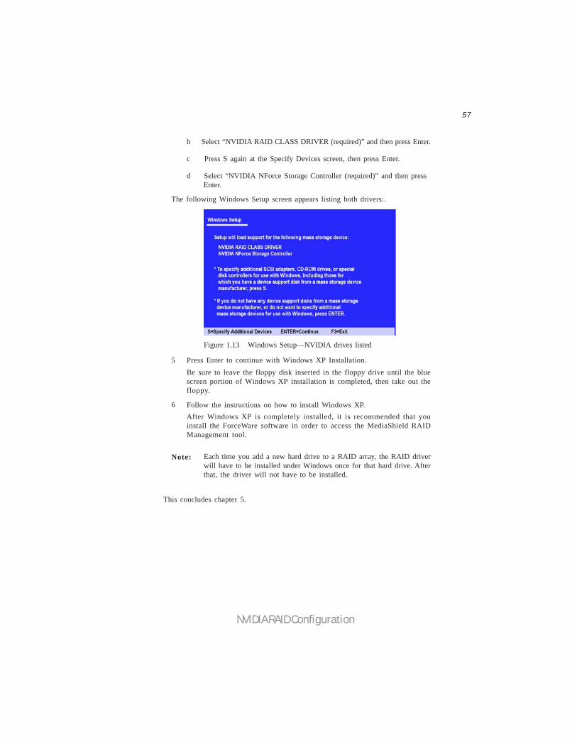
The following Windows Setup screen appears listing both drivers:.
Figure 1.13 Windows Setup—NVIDIA drives listed
Press Enter to continue with Windows XP Installation.Be sure to leave the floppy disk inserted in the floppy drive until the bluescreen portion of Windows XP installation is completed, then take out thefloppy.
Follow the instructions on how to install Windows XP.After Windows XP is completely installed, it is recommended that youinstall the ForceWare software in order to access the MediaShield RAIDManagement tool.
Note: Each time you add a new hard drive to a RAID array, the RAID driverwill have to be installed under Windows once for that hard drive. Afterthat, the driver will not have to be installed.
5
6
This concludes chapter 5.

58
NVIDIA RAID Configuration
Memo