manual - media.cranepedia.com
TRANSCRIPT

01/22/2009 20:33 4280401 PARKER PAGE 02
~'
)!AL.!!! I. OUA .lAIT '''ICtFICATtON
LORAIN· "
OPERATOR'MANUAL
C &704 MOTa-eRA E
"K Kaehrlngi Crane lid bcantar Group'.a.N.... Larain Praduct:ai •
R~v. #2 9-77 (Me-67 Al

01/22/2009 20:33 4280401I r
PARKER PAGE 03
. !II DESCRIPTION
ugh
es endIearentrolled.idad.
'.
The MC-670A (figure I) Is a carrier mounTed 70 +onmechln •i
tJre h~s an al I-welded turn+eble with Integral $ide fA-frame. It s ~quipped wIth double-drum boom hoist 8ssembly~ removcounterweight arid shear-bal I connection. The hoist friction ¢lutchecontrol Ied by a Ifu I I a I r system. The 5wlog cl utches ere a fr .5S Ist
'A balanced s~oe type, spring set~ orr released swIng brak$ Is p
The MC-67 barrier 15 on 8 x 4 chaSSis of 01 I-welded desIgn. A.n9tne~ hebvy duty transmIssion end through-drtva conneqtlon b
the ndem rear axles gives tr~vel speeds up to 40.2 M.P.H.axl ossemblles are double-reductIon gear driven, t~e firs
r u~tlon through hypofd gears and the frnol reductIon thpl~netary wheel hubs.
HydraulIc Outriggers with floats are standard. They! control lad from the carrIer cab or through the cabI wIndow. The outrIgger boxes are removable for ad
weight reduction If required.
( (
"-J(S)
ww
6
5-1/2" x 6"
(Early Machines)HHCT-270 (DIesel)
Opt. - (olsSe I )NTC-290
6
5-1/2" x 6"
6
{}pf~turesen
GK: 5-71N
<1-1/4" x 5"
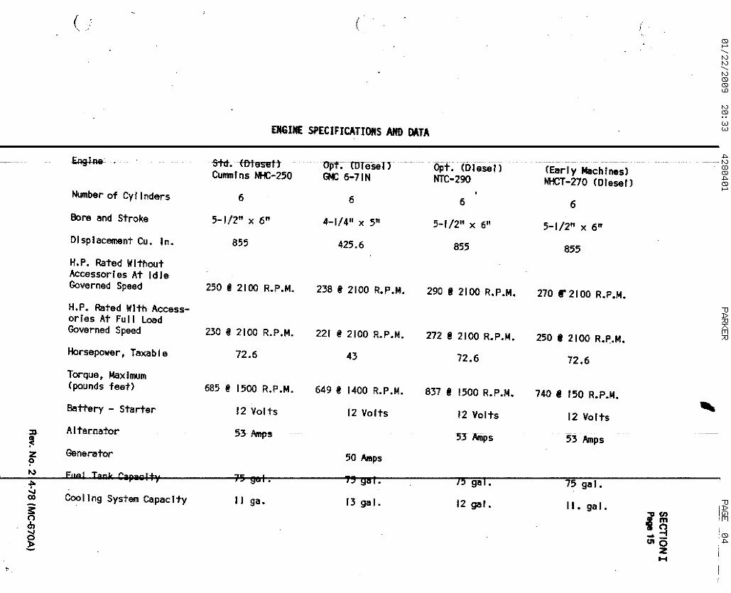
EJlGIIIE SPECIFICATIOItS AND DATA
6
5-1/2" x 6"
-stet. (D18S8 IICumnlns JH:-25D
Number of Cy! Irnlars
eore and Stroke
--------_...:...-_-----------------;;;CD(S)
-"(S)
>->
Displacement Cu. In. 855 425.6 855 855H. P. Rated WithoutAccessorIes At IdieGoverned Speed
H.P. Rated With Accessories At Fu II LoadGoverned Speed
Horsepower • TaxabIe
Torque. IoIax IlJtIm(pounds feet)
Battery - Starter
Alternator
Generator
Coo II ng System capac Jty
250 , 2100 R.P.M. 238 , 2100 R.P.M. 290 , 2100 R.P.M. 270 r 2100 R.P.M.
"DAJT01230 , 2100 R.P.M. 221 @2100 R.P.M. 272 @2100 R.P.M. 250 • 2100 R.P.M. AJ
72.6 43 72.6 72.6
685' 1500 R.P.M. 649 , 1400 R.P.M. 837 , 1500 R.P.M. 740 , 150 R.P.M.12 Vol ts 12 Volts 12 Volts 12 Volts!» -Amp-s nMips 53 MpS
50 Amps
15 901. " gal. 75 981- 75 gal.
12 gal. II. gal. "II gao [3 ga I•'J>.... en 10)
1 m !fTl
-g (S)
Ulo -"Z...

01/22/2009 20:33 4280401 PARKER PAGE 05
i
l~mShell is gene~81 Iy used for digging fo.oters,l~trenCh sandodk piling of loose materl~ls, loading haul Tng nits a d
~The clamshell Is capable of handlIng material both bove andeve I and can spot dump at any level of operation.
, !
( ..' OPERATION AS
GENERAL Thepier holes ..chllrg Ing bInbelow ground
¢L.AMSHELl
SE TION IIPa e 9
The 'c Iamshe I Iho Idin; I Ine •bucket. Thec los I ng I I ne
r~qulres the ~se of both hoist drums to provldei a clos ng and~he clostng line Is used for closing, hOlst,ng
rl ~nd du ping the
I~'ng I In. is used TO hold the bucket suspende when he5 .... Ieased to dump. . .
holdingl!!lnd
se the
l-tlon1'h theIt ne
forlever
.. :'contlnue the holding line brake applicatIon ~nd reia~e Just enough to 81 low the bucket to open. '
h:brskes as ~chlne Is beIng swung back to the ,digging posItIonI~wertng condl~lon.
OPERATION (FI UR~ 9). . i
FILLING AND H ISJING THE CLAMSHELL BUCKET Starting wIth openLbucketdIgging or fl Ilhg, engage closing lIne clutch by pul Ifng clo~rng IIand releasing clOsing I tne brake. ;Control depth by: use of holdIng line brake. As bucket eloses! engsg'Ine clutch b pul I fng back on holding line lever so that bot~ holdtclosing lines sp~1 equally. .DependIng on bstructlons, machine can be swung TO buckeT dumWfng powhlle.conTlnu ngtohotst. When bucket Is to desired helght'ipressholding Ifne nd'closlng line brakes as both holding line ~ndicloslnlevers are pu he~ forward releasing their respectrve clutchesf
HOTE; ·,T IS· CiSSARY TO BOOM !JP SLIGHTLY TO RELEASE THE BOO,", SAFET LOCKPAWL 8 OaE BOOMING DOWN. MAKE THIS A STANDARD PRACTICE.
Synchronize bTO give smoot
To empty buekclosing line
becomes skll led in clamshell work, tHe above qperatio 5 wll IoMous function.
As the operetbeccme e sync
SWINGING Eng ethe swing lever in the desired direction (pu~h to sw ng rIght,pull to swing lefT) and swing the bucket to the dumping poslt~on. Re ersethe swing lev to STOp the ~wlng.

01/22/2009 20:33
SECTION IIPlge 10
4280401
I!
PARKER PAGE 05
4 PARTCLOSINGLINE
DEAD END HERBFOR 3 OR 5PART LINE
_. - ...• - ..~-- ..._. -._.,- ._., . - - .._.~~- -ftPICAL =NG OF CLAMSHELL CLOSING LINE ::rORY'AR.IQOS p !1'S OF LINE IN BUClCET.
RETARDER PEDALtON MACHtNES WITH;RJ:TARDER ONLY)
SWING :LOCK LEWPULL UP to REPUSH oant TO
SWINGING AND D PING
I'
Figure 9. CI~mshell OperatIon.

01/22/2009 20:33 4280401 PARKER PAGE 07
SECTION IIPage 14
. ,
THE TO~QUE CONVERTER VERSUS THE PLATE CLUTCH. AND TH~HYDRAULIC COUPLING .
II
,.-..
usest
The technique n operatJng a machine equJpped with a To~que corlverter . $
somewhat dlffo ~nt than when equipped with a standard plate CI~tch orhydraulfc coup In;. Here fs D brief end simple compe~fson of.~he v~rrpower teke-off unHs. whIch will 8s~Ist the operator In obTalnl:ng theperformance fr the torque converter. - ' .
~
haftue
drive,
. :,\
plate clutch In the engaged posItion fonns l1!I dtlrect co pi tngIne and the output shaft. When too grea-t e loed' Is P18 ad onh.n lIfting excessIve loads, the engine wll I slpw down andr$fl ng c I ufches are not re Iee sed. .
tHO When a hydraulIc coupling, commonly called ~ fluIdthe engine and the output sheft, the coupling apts asthe eng'lne lind load. A hydraul Ie coup I fng dlfflers frthat when excessive loeds ~re encountered, fhe putput
:to 8· complete stop. The engine, however, wt Iii contiecf speed."
PLATE CLUTCHhefw.." the enthe engIne, assts f f If the 0
HYDRAULIC COUPIs used betwMcushion betweeprete clutch Iwill slip or erunnrng at red
TORQUE CONVERT A torque converter ~Iso acts ~s li cushIon bet~een th fo~dand engrne. I dflffers fran the hydraul rc coup I fng In that It lnutt1pl es theengine output rque. The torque conver~Gr builds up torque gr.du~lly ~s theloed Is applIed whereas ~ mechanical tr~nsmlsslon Increases torque by shiftIng step by sta • '. The lIImount of torque mulTlpl iCl!ltlon depends 9" the ImlTof the converte and the appl led load. As the torque Is Incre8sed~ ~h
operet Ing speed eire reduced.1,
speed,pickmed tolo~d
d
;
The main differ nCB In the operliltIon of ~ torque converter vers~5 ~ hy raul iccoupling Is th~ when a loed Is eppl led to 8 hydrauric couplln9~ the e Inewill Slow down nd lose horsepower, whereas the engine with a c<l>nverte 'willspeed up,.There ylncreastng horsepower and buildIng up torque In the nverter.
On a fluId drtv mechfne, when the engfne slows down to machInery star Ithe operator eu emetically relellises ~he clutches to al low the e~glne tup speed so he ~n resume· opare-tlon. ThIs s~me operator, Sf not aceus~ machine equip ed WiTh a converter wll I nliltural Iy keep on spplylng thexpecting the e g·the -to slow down. Instelll;d The engine will pick up speven though the me~hfnery Is stal led.
To melnt~in a 9 doperllltlng speed on a converter powered m~chf~e, the perator must dlsreg rdthe.sound and speed of the engine and rel,y om the pformance of the machine. The speed at which the load or buckeT'ts movS 9is the decidIng fet~or In determtnlng if the machine Is working wlthln Itscapabllttles. r mexlmum production, it Is tmport~nt to load the engi eand converter J st enough to keep the load movfng or the bucketjsllctnthrough the 8)(C eted m;,terlal. Just because the englne won't ~tall, d n'tthink the conve er leeks power. Oynaometer tests prove that 40nsrde blymore I)no pull a+talned by a converter equipped ~chlne.
Learn to run. r~ue converter equipped machine by EYE. not by EAR.

01/22/2009 20:33 4280401 PARKER PAGE 08
EeTION IIage 15
SPECIFICATIONS AND DATA
~235 R.P.M.
1400 R.P.M.
2235 R.P.M.
5
o
(1*
0**
0*
2
24 ~**
4 gal.~ vortsc' ~mps.
f g~ I.
147
341
• ••
• "I ..
. .
......... to l1li •
................ " ......
1400* III 'If •••
2300
2500
1600·
2300··
2600·· ~ ..
10 98 I ". " II ••
12 volts .•...•••...55 emps.. .. ....... "" II
68 ge I • .. .. II II 't "" ..
150 , 2440 R.P.M.
325 @ 2440 R.P.M.
.. .. • • • • .. .. .. • .. • .. • .. ... to ......
Eng I ne . • • • .• • I' • • •. _ .. '" to •• ~ • • • II • • • • • I' • .. STd. (Diesel) Opt. CDr.sel)Cummins V-504C Gt 6 53N
Number of CyllM4ers •••••••••.•••.••••••••• 6 •.••••••.•••••••• 6Bore and Sf e................... 4-5/8" x 3-3/4" ••••• 3,,;,7/ ff x 4-1/2"oi sp l.ocernent u ~ In. • •••••••• I' I' I' I' I' 5()4 I' •• I' ••• '*' • I aH.P. Rated Wf h :Accessorles at Ful I
load Govern Speed ••••••••••••••.•Torque of Eng n. at Ful I LoadGOverned Spa d ;(pounds feet) •••••••
Torque of OuT uf Sh~ft ~t Fullload Governe speed (pounds feet).. 412 I 1400 R.P.M. ••. 452
Torque, maxim m~ of Output ShaftaT St,1 I of on~erter (pounds feet) •.•••• 800 •••••••••••••••••
Speed of Eng I .~ Fu II Load,Full Throttl (~.P.M.) •.•••••.•••••••••• 2325 2 5
Speed of Engr e, No LoedFull Thro1"tl CR..P.M.) ••••••..•••..•••
Speed of Eng I e ot Stal I ofConverter (R P.J.1.) ••••••••••••••••••••
Speed of Torq • Converter OutputShaft, Full a~ at Ful IThrottle (R~
Speed of Torq ¢onverter ,OutputSheft, Ful I ~ at Ful IThrottle CR.
Speed of Torq ¢onverTer OutputShaft, No L 4t FullThrottle CR.
Speed ot Torq ~onver~er OutputSheft, No Lo at Ful lThrottle CR.
CoolIng Syste C~pecity .•••••••.•.••.••Battery - St~ er - Alternetor ••••..•..A' ternatot" ".. ..' ,. ill' .
Fuer nmk Cap\'ll
• Hand Throttl** Foot Thrott e
NOTE: Mechrne Is equIpped with toot throttle arrangement to provIde verspeedof norm I throttle settIng. ProvIdes for Increase of line spe s Whenhandlln llight loads. See Section XI for adjustmenT co41 opere fan.
I
'''-r'-'" ,."'

01/22/2009 20:33 4280401 PARKER PAGE 09
SECTION IIPage 16
SPECIFICATIONS AND DATA
' ..Jo__
o gal.2 volts5 amps.
ga I.
141 .'
322 •
*** (D esel)Curm.1 n C464C(CI f'O)
...
...
.. ...... '" I ••..............
. ' .
•••••• olJI ...
10 ge I.12 volts55 amps.68 gel.
820
148 8 2260 R.P.M.
Opt. <DIesel)CUII'm fns CT464P(CI7~)
345 • 2260 R.P.M.
early mllchlnes.
5 equipped wIth" foot throttle ~rrangemenT to p~ovfde 0 erspeed1hrott I8, 58tt In9. Prev Ides fol'" Increase of 11'n8 spee s when
nghi" loads. See Sect-Ion XI for adjustment and opereT Oh.
..........................Eng Ine •.•.••••
A I tern8t-or ~ .
* Hand ThroTt I** Foot Thrott I
Number of Cy I i d...-s ••... •. 9 '" •••• I • • • • • • • • • .. • 6 !" • • •
Bore and Strok ••••••••••••••• •.••••• 4-7/16" x 5" ••••••••Dlsplae-..ent C . ·In • ........... 11I *'.... 464 ~ ..••H.P. ~ted Wit Accessories e+ Full
Load Governed Speed ••••••.•••..•••.Torque of Engf e et Full loadGoverned Spee (pounds feet) •••••••
TorqY9 of Outp t Shaft at FullLoad Governed peed (pounds feet) •.• 452' 1400 R.P.M•••• 377 ITorque~ Maxlmu ~ of Output Shaftat Stall of C nverter (pounds feet) ••••..•
Speed of Engln ~ Ful f Lo~d~
Full· ThrOTtle (R.P.M.) •••••••..•••••••••. 2260 ••••••••••••••• 2Speed of Engln , No LODd~
Full ThroTtle (R.P.M.) 2500 2Speed of Eng'n et Stell ofCc.lnverter (R . •M.) 11' of • • • .. .. .. • • 2200 '" ••.
Speed of Torqu C~nverter OutputShaft, Full l d at Ful ITh rott I. (R. P .) ". ~ " .••• I • • • • • .. 1400* 'If •••
Speed of Torqu C~nverter OutputShaft, Full d at Ful IThrot-tle (R.P .) •••.•••••.•••••••••••••• 2300**............... 2
Speed of Torqu Converter OutputShaft, No Lo~ at FullThrott I e (R. P .). III • • • • • .. .. • • • .. • • • • • • • • • • • 1600* 'III •••
Speed of Torqu COnverter OutputShaft~ No Loa at FullThr-o'ttle (R.P .) •.. '11 2500* "' 11II .
Coo I fng System epac I ty .••...••••••••••.••B~ttery - St. r - Altern~~or .•••.••...•.
fuel T~nk Capa
NOTE:

01/22/2009 20:33 4280401 PARKER PAGE 10
MACHINE CONVERSION
SECT ON IIIPage 1
GENERAL
: l
~!
I. MC-67OA Moto-Crane EquippedWith 40 Ft. Ope~ Throat Boom •
. I) eOn be equIpped with tho fOllOWlng
l
front nd
'nil 0 en Throat Peak 800m. The conventlomlll (Open Throat)p n conneCTed pe w th a 25 ft. base sectlor end 8 15
ectJon. Center sections are evallable In IO.j20 and 30 ft.to make up TO a maxImum of 170 ft. of boom. i
T. ered Peak Seetlon. The 35 ft. long1tepereon Is a pIn connected Type usIng common baS8·.nd cen
tl1on5 wIth the conventIonal boom. Maximum length 170I I
ammer Held Boom. A two ft. hammer ,head top sfctlonIn connected to the conventIonal base or cen1-,r sectl
PermItting use as a hammer head crane boom fro~ 27 ft.I !1~7 ft. mexlmum. i
d. Jib. The Jib extension Is a'pln connecTed!Type wITei'"""ft. base section end a 10 ft. top sectrdm. 10
Insert sections are available to make up ~ mexlmu50 ft. A 12 ft. Jib mast Is used. Jlb!extensi
can be used wftb....1:h~~'i~,n.±J.9n~J _or +~P~l"'~9 .eaktype booms. A specl~1 20 ft.' boom center s etlanWTTh-rT~6~ckstay pend~nt anchors end (2) adap
ter lInks ara required when JIb xtensl n Isused wIth hammer head peak bo
e. Clamshel t. A rudomattc ta lIne .,,,.1 hcable Is avaIlable for co vertl the
machine to clamshel I op ration.
e.
••
The K:-670A Cre'ttachmen1's.
' ..
.-,-, ,-- _.. .. -_. .
Revi.ioh '1 6-1-is (MC6 OA)

01/22/2009 20:33 4280401 PARKER PAGE 11
s eTlON IVP ge 1
'\"--'" .MOVEMENT TO A NEW WORK SITE
GENERAL
The MC-670Acounterwelghreduction.and requires
OTQ-CRANE Is equipped wfth 8 pfn connecTed boom, removahd removable outrigger boxes for quick 8nd e8$y wetg
he remove I of these components can be handled by theno addrtJonal lifting equipment.
ble
hlne
DIMENSIONS A 0 WEIGHT
Table on pig 2 gives thedimensions. eral I weightsand loed drs I~ution oneach tandem it~ componentsInstalled or amoved.
C()ONTERWE GHT
. OPEN THROAT
Bocw. TIP SECTION
Ftgure I. MC-670A Moto-Crane.

01/22/2009 20"33 4 80401 PARKER PAGE 12
SECTION IV I
Page 2II
LOAD DISTRIBUTIO~ A~O WEIGHTS fOR MC-67OA (8 x 4)'POWRSPAN OUTRIGGE ~S : TURNTABLE: TU ~NTABLE
............
GROSS FACING FRONT" FAC NG REARWEIGHT FRONT REA~ FROIr REAR
l- Bas Ie Cr~ne • ••~ ••• '" .............. II ....... 62935 19796 4313' 277: 6 35199Less :8. Cou"terwef ~hllb. Front and ~ear Outr Igger
Boxes an BaDms. I
c. Complete 4 b' b-158 Offset Boom~Most, FI ~~ln9 Herness~ 800mHolst C;, ble and Boom Stops.
d. Hoist Cabl s
2. Add: Rear Out Igeer Box and Beams ... +6100 -1B83 +79aj ·1BBB +7983PO RSPAN) -.
3. Add: Front Ou rl~ger Box and Beems .. +6100 +4057 +204~ +405~ +2043PO RSPAN)
4. Add: Counterwl Ight • ..... 11\1 .............. +22000 -6700 +2870~ +166C b +5400
.5. Add: Load Hoi t table, Front Drum •.. +690 +120 +57Q +2C b +490
6. Add: 0-158 80c ~ ease~ Mast, FloatingHarness, Bo~ Holst Cable and
+82Q I:>800cn Stol s it ... '" ......... II ....... II ...... +5675 +4855 -284 +6520 ~.
7. Add: D-15B 15 Offset BOom Pe~k .••• _ +1940 +4145 -2205 -320 ~ +51458. Add: 0-158 '5 L¢lng Tapered
Boom Peal .. ,. , ..................... +2540 +7580 -504Q -641 ~ +8950
9. Add: P.L.L. Ft pn+ Drum .................... +625 +155· +47Q +13 D +495
10. Add: P.L.L. Dr l,Jm ............ '" ................ +420 +50 +37Q +14 b +280II • Add: 3rd. Drun .. 41 ............... + ......... " • +1450 +505 +945 +16 ) +129012. Add: CummIns Cr-464-p EngIne
With To que Converter ............ +100 -20 +12Q +6 ~ +3513. Add: GM 6V-53N Engine
With To "que Converter •••• '" t •• -150 +25 -17~ -8 -6514. Add: GM 6-71N ~ngine To Carrier ••••• -615 -775 +160 -77 +16015. Add: CummIns NffClt-210 Eng In6
To Carr er ................ ., ....... "t ... +100 +120 -20 +12 -20"16. 70 Ton~ 5 S/:ieave Hook 810ck 10.'Add: ~! ;
Boom Pe ~k '.................... "' ...... +1500 +3846 -23401 -3/5 +465517,. Add: 25 Ton~ I Shleave Hook 810ck To
Boom Pe k ................................. +1000 +2560 -1560! -2101 +3100
---_............
Rev. No.1 4·78 (MC-6 IOA~

:u~Zo- .
, (
Me-67OATRAYElINGWEIGHTS
(POWRSPAN)
TURIO'ABLE TURNTABLEFAe INt FRONT REAR FRONT RI\Nl DI>J\U.. ..
m,,",,, .. 'w, UUIKllilitRS OUTRIGGERS PEAK BASE FROt4T BEAB. we.~~.19796 43139 0 0 0 0 0 27736 35199· 62935
24651 43959 0 0 0 0 X 24891 43719 68610.
28796 41754 0 0 0 X X 21641 48909 70550
32853 43797 0 0 X X X 25698 50952 76650
30970 51780 0 X X X X 23815 58935 82750
24210 80480 X X X X X 40415 64335 104750
20125 82685 X X X 0 X 43620 59190 102810
26825 53485 0 X X 0 X 21020~ 53790 80810
28708 45502 0 0 X 0 X 28903 45807 14710
* B:Jan Sase I nc Ivdes a I I canponents I I sted , n 'tem 6.X Installed 011 machIne.o Removeafrom machIne
OJ(S)
WW
"0<1>• 1"1lD n"-I...wo ":z: D
Gl- 01<
>->w

01/22/2009 20:33
SECTION IVPage 4
4280401
I,
PARKER PAGE 14
~OAD DISTRIBUTION A"D WEIGHTS FOR MC-67OA (8 x 4),YERTI-POWER-SET 0 T~IGGERS
;
GROSSWEIGHT
TURNTABLEFACING FRONFRONT RE R
'~RNTABLE
FAC ING REARFR[ T . REAR
I. Basic Crane 1•• "' "' "' ..
Less: !,
1I. Cou nterwe I hTI,b. Front and ear Outrigger
!loxes IIn Bj;lems.c. Complete 4 ' ~-15B Offset Boom,
Mellt, fl at~ng Harness, BoomHolst Ca leland Boom Stops.
, d. Ho Ist Cllb It s '!
63125 19830 432 5 27/"0 35355
-18 5 +7685
+39b5 +1965
-31'5 +4655
-21<P +3100
•
-20
+35
-65
+160
+8950
+495
+280
+1290
+ 5
+1 0
- 5
-7 5
-64 0
+1 0
+1 0
+1 0
·28 '5 +8520
-32 '5 +5145
+166 0 +5400
+2 0 +490
+6~-22q,
-:~+37b
I
+94~
II
+12pI
I
-17~
+16p
-2~I,
-234~I
I
-156?
+7615
+19E5
+287(0
+570'I
+120
-20
+25
-775
+3905
-1815
-6700
+120
+4855+4145
+7580
+155
+50
+505
+3840
+2560
+100
-150
-615
+100
+5870
+5870
+5675
+1940
+2540
+625+420
+1450
+1500
+1000
+22000
+690
,
2. Add: Rellr Outr Ig$er Box lind Beams •••.(VEF if-I tPOWER-SETl
3. Add: Front Ou~ "I"ger Box II nd Beams •••(VEF In tPOWER-SETl
4. Add: CounterwE Ig~t .
~. Add: LOIld HoI!1t- deble, Front Drum ..
6. 'Add: D-15B Bcx ~se, Mast, FloatingHarness, I3o<:im Holst Ceble andBcx::xn S'to~ '"'I oil ..
7. Add: D-158 15' Offset Boom Peak ••••.•
8. Add: D-15B 35' L~ng TaperedBoom Pe,e k .. +'" .. .. • • .. .. .. .. .. .. .. .. .. .. .. .. .. .. .. ..
9. Add: P;L.L. Fr n~ Drum ••••.••••••••••10. Add: P. L. L. Re r brum ..
II. Add: 3rd. Drum • -' .
12. Add: CummIns C -4~4-P EngIneWith Tor uei Converter ..
13. Add: GM 6V-53N EngineWith Tor uel Converter ••••.•••••
14. Add: GM 6-71N ngilne To Carrier ......
I S. Add~ Cumm I ns NjeT!-270 Eng IneTo Carri r It "' ..
16. Add: 70 Ton, 5 Shj;leve Hook Block Tof3c)Qn Pea .. .. .. .. .. . .. .. .. .. .. .. .. .. .. ... .. .. .. .. .. II!
17. Add: 25 Ton, I Sh,ave Hook Block To800m Pea . , .

(
1«:-670A,
TRAVELING WEIGHTS(VERTI-POWER-SET)
TURNTABLE TURNTABlEFACING "-ONT REAR FRONT ' BOOJ.I ...~ ...,. DrAft
' ..
PEAK BASE FRONT_..•-.
"" .... ,.,,,....,, 001 ."R~AIt WE !GHY. , .,. " ,
. " . --" --19830 43295 0 0 0 0 0 'Z1710 35355 63125
24685 44115 0 0 0 0 X 24925 43875 68800
28830 41910 0 0 0 X X 21675 49065 70740
32835 43775 0 0 X X X 25719 50091 76610
30748 51732 0 X X X X 23662 5881a 82480
24169 80311 X X X X X 40193 64287 104480
20058 82482 X X X 0 X 43365 59175 102540
26638 53902 0 X X 0 X 26833 53707 80~0
28707 45963 0 0 X 0 X 28902 45768 74670
* Boom Base includes a I I components 11 sted rn 1tem 6.X Installed on machine.o Removed from machine.
~-1...<nO
:z...<
OJ(S)
ww
'lJDGl01
>..>(Jl
~I-'
-----t'0t'0
-----t'0r" Ut~.,., ~
,fC n LD1110-1
!O'l E t'0Z ~..- w-< w
I
t .p..-- t'0
CD~
j .p..~I-'
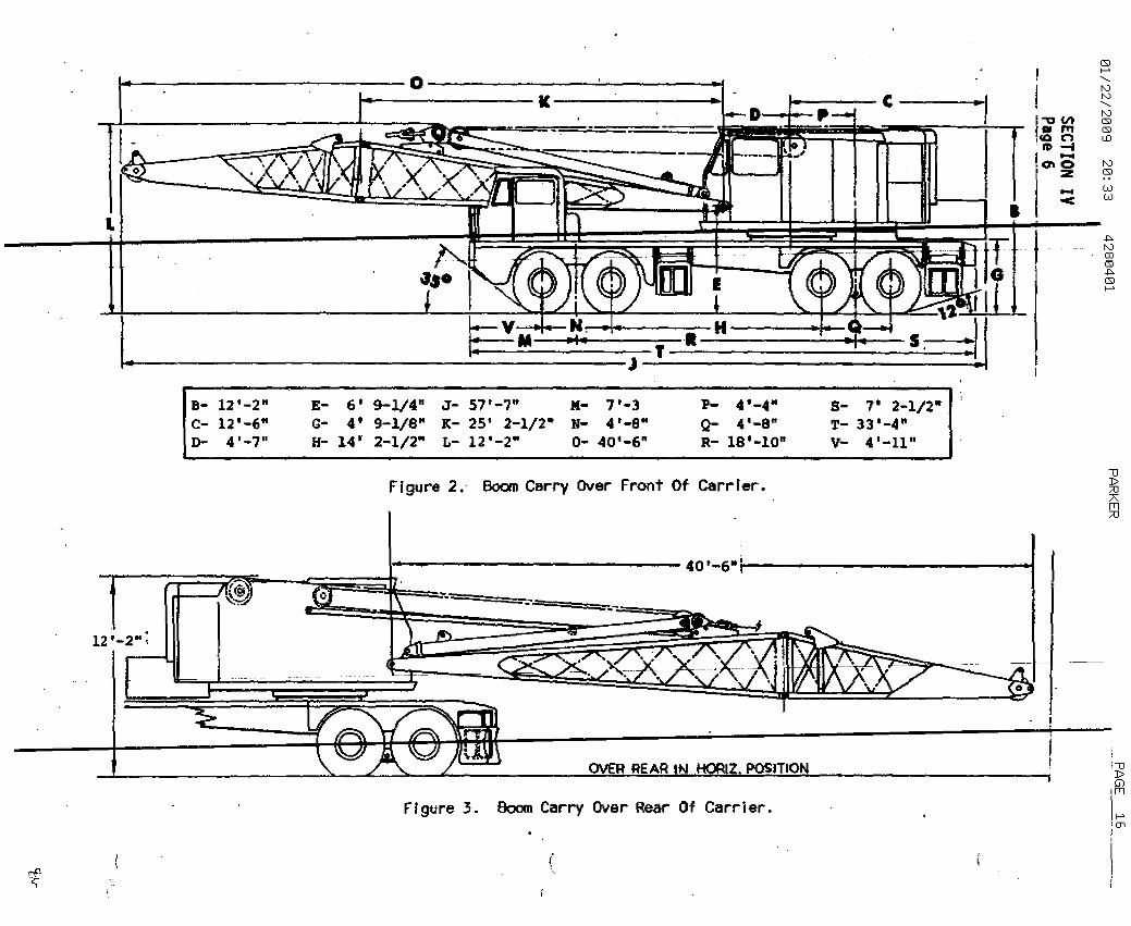
s- " 2-1/2T- 33'-4"v- 4 1 -11"
--------l·~lf-I..-- 5--..J,
E- 6' 9-l/4 lt J- 57 t -7 1t M- 7 t -3 p- 4'-4"G- 4' 9-1/8t41 K- 25' 2-1/2- N- 4 t -S" Q- 4'-8"H- 14' 2-1/2" L- 12'-2" 0- 40'-6" R- 1S'-lOtt
B- 12'-2"c- 12'-6"D- 4 1 -7"
l.
f -o
L
Frgure 2.- Boom Carry Over Front Of Carr rer."1]D;::0TfTl;::0
;"1]DGlfTl
Z. POSITIONOVER REAR N
1..·--------------- 40 ' -6..ijoo--------------.-..01
-.r:c~'------t:~~=:
12 '_2 01 ;
Ff gt.t re 3. Boom Carry Ova r Rear Of Carr j er .I-'en
(

01/22/2009 20:33 4280401 PARKER PAGE 17
SE TION IV'Pa e 7
$-3/4"lIO"111-1/2""
-13/4"0"1"1/2""
g~rs.
9-,77 01 670A)
"A I III I A- 9'
F- 9'-U.., 10'z- 11 '-I
.<
i "
~ 't5"......- ,
"'¢)~ 0
l'J'I~"lIlT'lI m'-----g
I· U I I.
z "InO Z,
F ~u ..e 4. Rellr View With Vertl-RQwer-Set Outrlg
•A -II
A- 9' IlF- 9'-1u- 10' 1Z..- 11'-0
AA 0'-I DB 0'-
$' A J~ I 1ftA_~~ I •~..i ' I
n llif n If 1] fi 1]Tt- I .'" ju,
• z "l" z •
Figure 5. Rellr View With Pbwrsplln Outriggers.
Rev. #1!
•
!,,:--. '..~ ..