manual mbe 4000 taller
TRANSCRIPT

7/22/2019 Manual Mbe 4000 Taller
http://slidepdf.com/reader/full/manual-mbe-4000-taller 1/630
7/22/2019 Manual Mbe 4000 Taller
http://slidepdf.com/reader/full/manual-mbe-4000-taller 2/630
7/22/2019 Manual Mbe 4000 Taller
http://slidepdf.com/reader/full/manual-mbe-4000-taller 3/630
MBE 4000 SERVICE MANUAL
ABSTRACT
This manual provides instruction for servicing the MBE 4000 Diesel Engine. Specifically, a basic
overview of each major component and the system, along with the recommendations for removal,
cleaning, inspection, criteria for replacement, repair, installation, and mechanical troubleshooting
are contained in this manual.
TRADEMARK INFORMATION
Loctite® is a registered trademark of Henkel Corporation. Wabco® is a registered trademark
of American Standard, Inc. Hengst® is a registered trademark of Walter Hengst GMBH & Co.
Perma-Lok® is a registered trademark of National Starch and Chemical Investment Holding
Corporation. Henkel® is a registered trademark of Henkel Corporation.
ENGINE EXHAUST
Consider the following before servicing engines:
PERSONAL INJURY
Diesel engine exhaust and some of its constituents areknown to the State of California to cause cancer, birthdefects, and other reproductive harm.□ Always start and operate an engine in a well ventilated
area.□ If operating an engine in an enclosed area, vent the
exhaust to the outside.
□ Do not modify or tamper with the exhaust system or emission control system.
All information subject to change without notice.
DDC-SVC-MAN-0023 Copyright © 2009 DETROIT DIESEL CORPORATION i
7/22/2019 Manual Mbe 4000 Taller
http://slidepdf.com/reader/full/manual-mbe-4000-taller 4/630
MBE 4000 SERVICE MANUAL
All information subject to change without notice.
ii DDC-SVC-MAN-0023 Copyright © 2009 DETROIT DIESEL CORPORATION

7/22/2019 Manual Mbe 4000 Taller
http://slidepdf.com/reader/full/manual-mbe-4000-taller 5/630
MBE 4000 SERVICE MANUAL
TABLE OF CONTENTS
GENERAL INFORMATION ...................................................................... 1
SCOPE AND USE OF THIS MANUAL .................................................... 3GENERAL DESCRIPTION ...................................................................... 3ELECTRONIC ENGINE CONTROL SY STEM ......................................... 4ENGINE BRAKING POWER .................................................................... 7GENERAL SP ECIFICATIONS AND ENGINE VIEWS ............................. 7ENGINE MODEL AND SE RIAL NUMBER ............................................... 13EXHAUST GAS RECIRCULATION (EGR) SY STEM ............................... 15SAFETY INSTRUCTIONS AND PRECAUTIONS .................................... 19ENGLISH TO METRIC CONVERSION .................................................... 28DECIMAL AND METRIC EQUIVALENTS ................................................ 29 TORQUE SP ECIFICATIONS ................................................................... 31
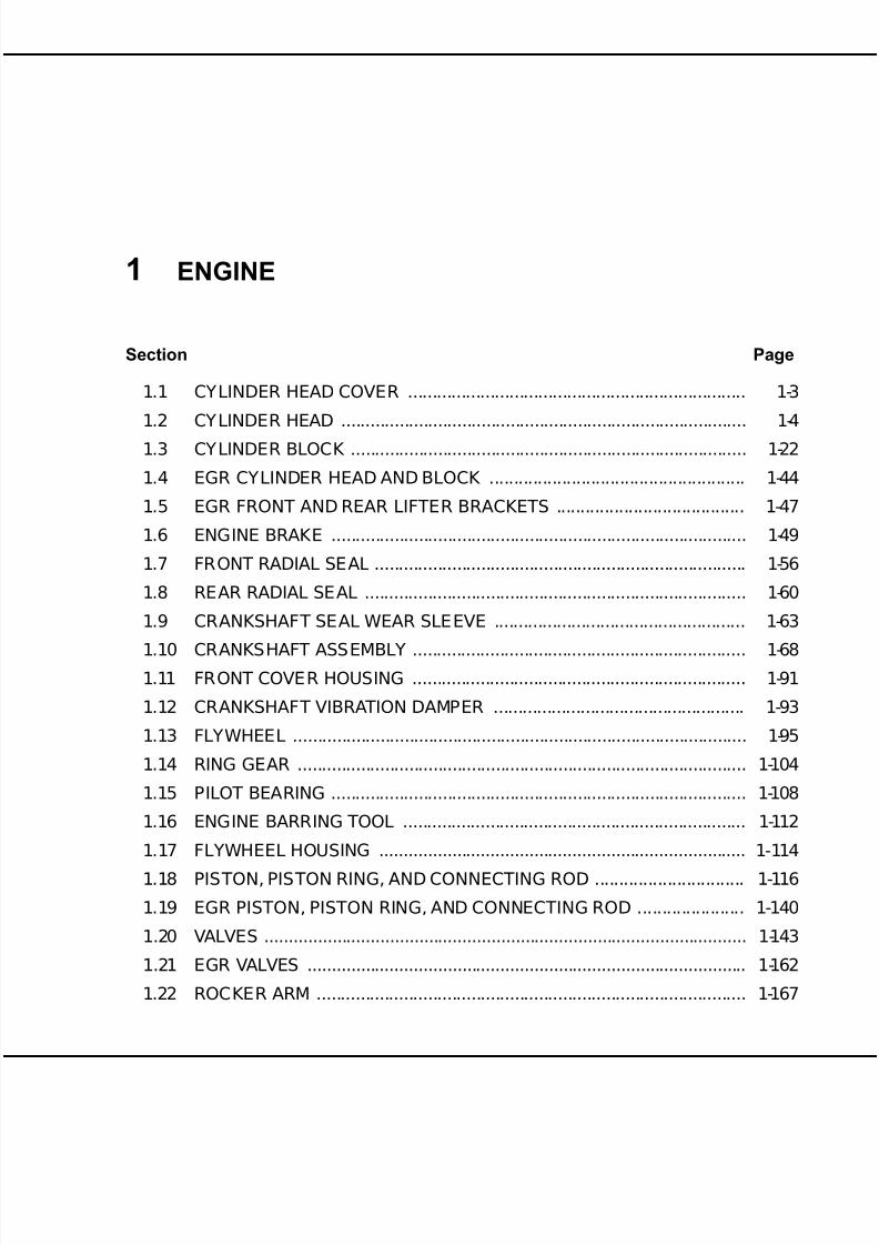
1 ENGINE1.1 CYLINDER HEAD COVER ...................................................................... 1-31.2 CY LINDER HEAD .................................................................................... 1-41.3 CY LINDER BLOCK .................................................................................. 1-221.4 EGR CYLINDER HEAD AND BLOCK ..................................................... 1-441.5 EGR FRONT AND REAR LIFTER BRACKETS ....................................... 1-471.6 ENGINE BRAKE ...................................................................................... 1-491.7 FRONT RADIAL SEAL ............................................................................. 1-561.8 REAR RADIAL SEAL ............................................................................... 1-601.9 CRANKSHAFT SEAL WEAR SLEEVE .................................................... 1-631.10 CRANKSHAFT ASSEMBLY ..................................................................... 1-681.11 FRONT COVE R HOUSING ..................................................................... 1-911.12 CRANKSHAFT VIBRATION DAMPER .................................................... 1-931.13 FLYWHEEL .............................................................................................. 1-951.14 RING GEAR ............................................................................................. 1-1041.15 PILOT BEARING ...................................................................................... 1-1081.16 ENGINE BARRING TOOL ....................................................................... 1-1121.17 FLYWHEEL HOUSING ............................................................................ 1-1141.18 PISTON, PISTON RING, AND CONNECTING ROD ............................... 1-1161.19 EGR PISTON, PISTON RING, AND CONNECTING ROD ...................... 1-1401.20 VALVES .................................................................................................... 1-143
1.21 EGR VALVES ........................................................................................... 1-1621.22 ROCKER ARM ......................................................................................... 1-1671.23 CAMSHAFT AND CAMSHAFT POSITION SENSOR .............................. 1-1711.24 EGR CAMSHAFT ..................................................................................... 1-1811.A ADDITIONAL INFORMATION .................................................................. 1-183
2 FUEL SYSTEM
2.1 INJ ECTOR UNIT PUMP ........................................................................... 2-32.2 EGR INJ ECTOR UNIT PUMP .................................................................. 2-15
All information subject to change without notice.
DDC-SVC-MAN-0023 Copyright © 2009 DETROIT DIESEL CORPORATION iii
7/22/2019 Manual Mbe 4000 Taller
http://slidepdf.com/reader/full/manual-mbe-4000-taller 6/630
MBE 4000 SERVICE MANUAL
2.3 HIGH PRESSURE FUEL LINE AND TRANSFER TUBE ......................... 2-162.4 FUEL INJ ECTOR NOZZLE ...................................................................... 2-262.5 EGR FUEL INJ ECTOR NOZZLE ............................................................. 2-342.6 PROTECTIVE SLEEVE ........................................................................... 2-352.7 DDEC-ELECTRONIC CONTROL UNIT ................................................... 2-392.8 FUEL HEAT EXCHANGER ...................................................................... 2-44
2.9 FUEL FILTER ........................................................................................... 2-472.10 FUEL FILTER HOUSING ......................................................................... 2-502.11 FUEL FILTER BRACKET ......................................................................... 2-542.12 FUEL PUMP ............................................................................................. 2-572.13 FUEL PUMP DRIVE ................................................................................. 2-612.14 FUEL SY STEM INSPECTION ................................................................. 2-652.A ADDITIONAL INFORMATION .................................................................. 2-73
3 LUBRICATION SYSTEM
3.1 LUBRICATION SYSTEM DESCRIPTION ................................................ 3-33.2 OIL PAN ................................................................................................... 3-53.3 PISTON OIL SP RAY NOZZLE(S) ............................................................ 3-113.4 CAMSHAFT LUBRICATION SP RAYER ................................................... 3-173.5 OIL PUMP AND SUMP PIPE ................................................................... 3-193.6 OIL FILTER .............................................................................................. 3-273.7 OIL HEAT EXCHANGER/FILTER HOUSING .......................................... 3-293.8 OIL PRESSURE/TEMPERATURE SENSOR ........................................... 3-343.A ADDITIONAL INFORMATION .................................................................. 3-37
4 COOLING SYSTEM
4.1 COOLING SY STEM ................................................................................. 4-34.2 COOLANT PUMP .................................................................................... 4-74.3 EGR COOLANT PUMP ............................................................................ 4-18
4.4 FRONT IDLER AND TENSIONER SUPPORT ........................................ 4-194.5 THERMOSTAT ......................................................................................... 4-224.6 EGR THERMOSTAT HOUSING .............................................................. 4-274.7 COOLANT TEMPERATURE SENSOR .................................................... 4-294.A ADDITIONAL INFORMA TION .................................................................. 4-31
5 FUEL, LUBRICATING OIL, AND COOLANT
5.1 FUEL ........................................................................................................ 5-35.2 LUBRICATING OIL .................................................................................. 5-55.3 COOLANT ................................................................................................ 5-75.A ADDITIONAL INFORMATION .................................................................. 5-13
6 AIR INTAKE SYSTEM6.1 INTAKE MANIFOLD ................................................................................. 6-36.2 CHARGE PRESSURE/TEMPERATURE SENSOR ................................. 6-56.3 TURBOCHARGER ................................................................................... 6-66.A ADDITIONAL INFORMATION .................................................................. 6-17
7 EXHAUST SYSTEM
7.1 EXHAUST MANIFOLD ............................................................................. 7-37.2 EXHAUST BRAKE ASSEMBLY ............................................................... 7-6
All information subject to change without notice.
iv DDC-SVC-MAN-0023 Copyright © 2009 DETROIT DIESEL CORPORATION

7/22/2019 Manual Mbe 4000 Taller
http://slidepdf.com/reader/full/manual-mbe-4000-taller 7/630
MBE 4000 SERVICE MANUAL
7.3 EGR EXHAUST MANIFOLD .................................................................... 7-147.4 EGR COOLER AND COOLER SUPP ORT BRACKET ............................ 7-267.5 EGR CONTROL VALVE, GAS OUTLET PIPE, AND GAS MIXER .......... 7-477.6 EPV (ELECTRONIC PROPORTIONAL VALVE) AND WABCO®AIR
SOLENOID VALVE ................................................................................... 7-547.7 HENGST BREATHER FILTER ................................................................. 7-58
7.A ADDITIONAL INFORMATION .................................................................. 7-678 ELECTRICAL EQUIPMENT
8.1 DRIVE BELTS .......................................................................................... 8-38.A ADDITIONAL INFORMATION .................................................................. 8-15
9 POWER TAKE-OFF
9.1 FRONT ENGINE POWER TAKE-OFF (FEPTO) ...................................... 9-39.2 REAR ENGINE POWER TAKE-OFF (REPTO) ........................................ 9-7
10 SPECIAL EQUIPMENT
10.1 AIR COMP RESS OR FLANGE ................................................................. 10-310.2 AIR COMP RESSOR ................................................................................ 10-5
10.A ADDITIONAL INFORMATION .................................................................. 10-11
11 OPERATION AND VERIFICATION
11.1 PREPARATION FOR A FIRST TIME START ........................................... 11-311.2 STARTING THE ENGINE ........................................................................ 11-811.3 RUNNING THE ENGINE ......................................................................... 11-1111.4 STOPPING THE ENGINE ........................................................................ 11-13
12 ENGINE TUNE-UP
12.1 VALVE LASH CHECKING ........................................................................ 12-312.2 ADJ USTING VALVE LASH ...................................................................... 12-9
13 PREVENTIVE MAINTENANCE
13.1 SCHEDULE D INTERVALS ...................................................................... 13-3
14 ENGINE STORAGE
14.1 PREPARING ENGINE FOR STORAGE .................................................. 14-3
15 TROUBLESHOOTING THE ELECTRONIC ENGINE CONTROL
SYSTEM
15.1 ELE CTRONIC ENGINE CONTROL SY STEM ......................................... 15-3
16 GENERAL MECHANICAL TROUBLESHOOTING
16.1 MECHANICAL TROUBLESHOOTING .................................................... 16-3
17 LOW POWER CONCERN
17.1 FACTORS THAT AFFECT WHEEL HORSEP OWER .............................. 17-317.2 LOW HORSEPOWER INTERVIEW ......................................................... 17-617.3 AERATED FUEL ..................................................................................... 17-1317.4 RESTRICTED AIR CLEANER ELEMENT ............................................... 17-1517.5 RESTRICTED OR CRACKED CHARGE AIR COOLER OR LEAKING
INTAKE MANIFOLD ................................................................................. 17-1617.6 FAULTY EXHAUST SY STEM .................................................................. 17-18
All information subject to change without notice.DDC-SVC-MAN-0023 Copyright © 2009 DETROIT DIESEL CORPORATION v
7/22/2019 Manual Mbe 4000 Taller
http://slidepdf.com/reader/full/manual-mbe-4000-taller 8/630
MBE 4000 SERVICE MANUAL
17.7 HIGH INLET AIR TEMPERATURE .......................................................... 17-2017.8 VERIFICATION OF POWER WITH CHASSIS DYNAMOMETER ........... 17-22
INDEX ................................................................................................. Index-1
All information subject to change without notice.
vi DDC-SVC-MAN-0023 Copyright © 2009 DETROIT DIESEL CORPORATION

7/22/2019 Manual Mbe 4000 Taller
http://slidepdf.com/reader/full/manual-mbe-4000-taller 9/630
GENERAL INFORMATION
Section Page
SCOPE AND USE OF THIS MANUAL ....................................................... 3
GENERAL DESCRIPTION ......................................................................... 3ELECTRONIC ENGINE CONTROL SY STE M ............................................ 4
ENGINE BRAKING POWER ...................................................................... 7
GENERAL SPECIFICATIONS AND ENGINE VIEWS ................................ 7
ENGINE MODEL AND SERIAL NUMBER ................................................. 13
EXHAUST GAS RECIRCULATION (EGR) SY STEM ................................. 15
SAFETY INSTRUCTIONS AND PRECAUTIONS ...................................... 19
ENGLISH TO METRIC CONVERSION ...................................................... 28
DECIMAL AND METRIC EQUIVALENTS ................................................... 29
TORQUE SPECIFICATIONS ...................................................................... 31

7/22/2019 Manual Mbe 4000 Taller
http://slidepdf.com/reader/full/manual-mbe-4000-taller 10/630
MBE 4000 SERVICE MANUAL
All information subject to change without notice.
2 DDC-SVC-MAN-0023 Copyright © 2009 DETROIT DIESEL CORPORATION

7/22/2019 Manual Mbe 4000 Taller
http://slidepdf.com/reader/full/manual-mbe-4000-taller 11/630
MBE 4000 SERVICE MANUAL
SCOPE AND USE OF THIS MANUAL
This manual contains complete instructions on operation, adjustment (tune-up), preventive
maintenance, and repair (including complete overhaul) for the MBE 4000 engine. This manual
was written primarily for persons servicing and overhauling the engine. In addition, this manual
contains all of the instructions essential to the operators and users. Basic maintenance and
overhaul procedures are common to all MBE 4000 engines, and apply to all engine models.This manual is divided into numbered sections. Section one covers the engine (less major
assemblies). The following sections cover a complete system such as the fuel system, lubrication
system, or air system. Each section is divided into subsections which contain complete
maintenance and operating instructions for a specific engine subassembly. Each section begins
with a table of contents. Pages and illustrations are numbered consecutively within each section.
Information can be located by using the table of contents at the front of the manual or the table of
contents at the beginning of each section. Information on specific subassemblies or accessories
within the major section is listed immediately following the section title.
GENERAL DESCRIPTION
The MBE 4000 Engine described in this manual is a water-cooled, four-stroke, direct injection
diesel engine. The cylinders are arranged in line. Each cylinder has a separate fuel injection pump
(unit pump) with a short injection line to the injection nozzle, which is located in the center of
the combustion chamber. The unit pumps are attached to the crankcase and are driven from the
camshaft. Each cylinder has two intake valves and two exhaust valves.
Charge-air cooling and an exhaust gas turbocharger are standard equipment on all MBE 4000
engines.
The engine has a fully electronic contr ol system, which regulates the injection quantity and timing
using solenoid valves, allowing extremely low-emission operation. The control system consists of
an engine-resident pump and nozzle control unit (the DDEC-ECU) and a vehicle control unit (the
DDEC-VCU). The two are connected by a proprietary datalink.
Engine braking is controlled by a pneumatically-operated exhaust brake on the turbocharger and
by a constant-throttle system. For greater braking power, an optional turbo brake is available.
The cylinder block has integrated oil and water channels. The upper section of the cylinder bore
is induction-hardened. The six individual cylinder heads are made of cast iron. The cylinder head
gasket is an adjustment-free seal with rubber sealing elements.
The pistons are made of aluminum alloy with ring carriers and a shallow combustion chamber
recess. The pistons are cooled by oil spray nozzles.
The crankshaft is precision-forged with seven main bearings and eight custom-forged counter weights, and a vibration damper at the front end.
The camshaft is made of induction-hardened steel and has seven main bearings. Each cylinder has
cams for intake and exhaust valves and a unit pump.
The valves are controlled by mushroom tappets, pushrods, and rocker arms. The intake and
exhaust valves are opened and closed by a valve-guided bridge.
All information subject to change without notice.
DDC-SVC-MAN-0023 Copyright © 2009 DETROIT DIESEL CORPORATION 3
7/22/2019 Manual Mbe 4000 Taller
http://slidepdf.com/reader/full/manual-mbe-4000-taller 12/630
MBE 4000 SERVICE MANUAL
There is a force-feed lubricating oil circuit supplied by a gear-type oil pump. This pump is
positioned at the rear of the oil pan and driven by gears from the crankshaft. The oil heat
exchanger is located near the front of the crankcase on the right-hand side near the turbocharger.
The gear-type fuel pump is located near the front of the crankcase on the left hand side. The pump
is driven from the forward end of the camshaft.
The air compressor, with a power-steering pump attached, is driven by a gear on the camshaft.The engine is cooled by a closed system using recirculated coolant; temperature is regulated
automatically by a thermostat.
There are three drive belts, each with its own automatic belt tensioner. The alternator and coolant
pump (and any other accessories) are driven by a main drive belt. The fan and the air conditioner
compressor are each driven by their own drive belt.
ELECTRONIC ENGINE CONTROL SYSTEM
The engine is equipped with a fully electronic control system. Besides the engine and its related
sensors, this system is composed of the DDEC-ECU, or engine control unit, and the DDEC-VCU,
or vehicle control unit. The two control units are connected by a proprietary datalink through
which all necessary data and information can be exchanged. The DDEC-VCU then broadcasts
all information on the J1587 and J1939 datalinks, where it can be read by minidiag2, Nexiq™
Diagnostic Data Reader (DDR), or Detroit Diesel Diagnostic Link® (DDDL) PC software.
The DDEC-ECU monitors both the engine and the datalink. When a malfunction or other
problem is detected, the system selects an appropriate response; for example, the emergency
running mode may be activated.
All information subject to change without notice.
4 DDC-SVC-MAN-0023 Copyright © 2009 DETROIT DIESEL CORPORATION

7/22/2019 Manual Mbe 4000 Taller
http://slidepdf.com/reader/full/manual-mbe-4000-taller 13/630
MBE 4000 SERVICE MANUAL
DDEC-ECU — Engine-Resident Control Unit
The DDEC-ECU control unit is located on the left-hand side of the engine. See Figure 1. The
DDEC-ECU processes the data received from the DDEC-VCU, for example the position of the
accelerator pedal, engine brake, etc. These data are evaluated together with the data from the
sensors on the engine, such as, charge and oil pressure and coolant and fuel temperature. The
data is then compared to the characteristic maps or lines stored in the DDEC-ECU. From thesedata, quantity and timing of injection are calculated and the unit pumps are actuated accordingly
through the solenoid valves.
Figure 1 DDEC-ECU Control Unit Location
NOTE: To obtain a replacement DDEC-ECU, all the data given on the DDEC-ECU label arerequired.
All information subject to change without notice.
DDC-SVC-MAN-0023 Copyright © 2009 DETROIT DIESEL CORPORATION 5
7/22/2019 Manual Mbe 4000 Taller
http://slidepdf.com/reader/full/manual-mbe-4000-taller 14/630
MBE 4000 SERVICE MANUAL
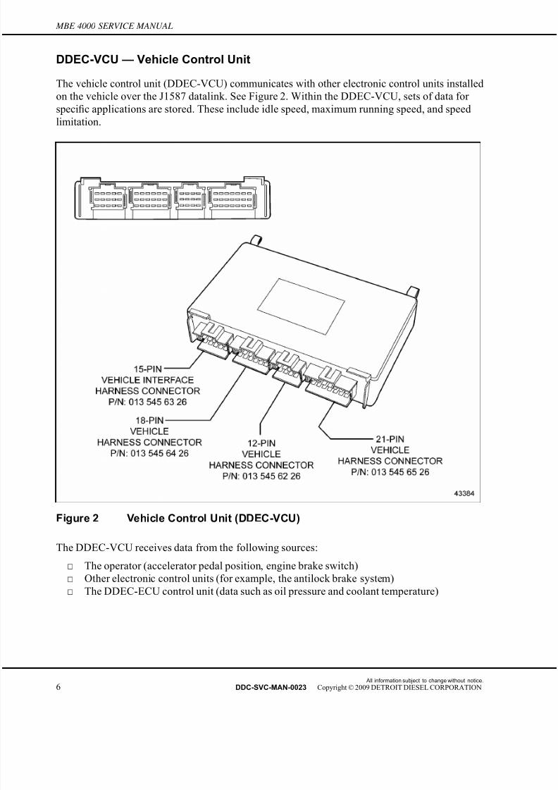
DDEC-VCU — Vehicle Control Unit
The vehicle control unit (DDEC-VCU) communicates with other electronic control units installed
on the vehicle over the J1587 datalink. See Figure 2. Within the DDEC-VCU, sets of data for
specific applications are stored. These include idle speed, maximum running speed, and speed
limitation.
Figure 2 Vehicle Control Unit (DDEC-VCU)
The DDEC-VCU receives data from the following sources:
□ The operator (accelerator pedal position, engine brake switch)
□ Other electronic control units (for example, the antilock brake system)
□ The DDEC-ECU control unit (data such as oil pressure and coolant temperature)
All information subject to change without notice.
6 DDC-SVC-MAN-0023 Copyright © 2009 DETROIT DIESEL CORPORATION
7/22/2019 Manual Mbe 4000 Taller
http://slidepdf.com/reader/full/manual-mbe-4000-taller 15/630
MBE 4000 SERVICE MANUAL
From these data, instructions are computed for controlling the engine and transmitted to the
DDEC-ECU via the proprietary datalink. The DDEC-VCU controls various systems, for example,
communications with the datalink, the engine brake, and the constant-throttle valves. If the
engine control system detects a fault, the appropriate fault code is broadcast on the datalink
and can be read using minidiag2. When there is a fault, the code for the control u nit reporting
the fault can be read directly on the display.
ENGINE BRAKING POWER
Exhaust Brake/Constant-Throttle Valves
To increase braking performance, the engine is equipped with an exhaust brake on the
turbocharger in conjunction with constant-throttle valves on the cylinder head.
NOTE: The constant-throttle values are activated by engine oil pressure.
The exhaust back-pressure is used by the exhaust brake to increase braking performance.
Optional Turbo Brake
For high braking output, the MBE 4000 engine can be equipped with an optional turbo brake.
The turbo brake increases the air mass flow through the engine to provide up to 600 brake
horsepower. The turbo brake can be operated either manually or automatically, through the
cruise control function.
Because the charge air pressure is maintained at a high level during braking, full throttle response
is available immediately, if the operator desires it, without any turbo lag.
The turbo brake is maintenance-free, highly reliable, and adds virtually no weight to the engine.
GENERAL SPECIFICATIONS AND ENGINE VIEWS
For a general view of the MBE 4000 engine, showing major components, see Figure 3 for the
left-hand side, and see Figure 4 for the right-hand side.
For a general view of the MBE 4000 engine, showing ports and fluid lines, see Figure 5 for the
left-hand side and see Figure 6 for the right-hand side.
For a general view of the MBE 4000 engine, showing sensor locations, see Figure 7. Two sensors
are not easily visible from the left-hand side of the engine: the charge pressure/temperature
sensor, located on the right-hand side of the charge air manifold, and the oil pressure/temperature
sensor located at the base of the oilfi
lter.
All information subject to change without notice.
DDC-SVC-MAN-0023 Copyright © 2009 DETROIT DIESEL CORPORATION 7

7/22/2019 Manual Mbe 4000 Taller
http://slidepdf.com/reader/full/manual-mbe-4000-taller 16/630
MBE 4000 SERVICE MANUAL
1. Front Camshaft Cover 8. Power Steering P ump
2. Thermostat Housing 9. DDEC-ECU Control Unit
3. Coolant Pump 10. Fuel Heat Exchanger
4. Charge-Air (Intake) Manifold 11. Oil Pan
5. Engine Trim Cover 12. Fuel Filter
6. Crankcase Breather 13. Fuel Pump
7. Air Compressor 14. Air Conditioner Compressor
Figure 3 Left Side, Major Engine Components
All information subject to change without notice.
8 DDC-SVC-MAN-0023 Copyright © 2009 DETROIT DIESEL CORPORATION

7/22/2019 Manual Mbe 4000 Taller
http://slidepdf.com/reader/full/manual-mbe-4000-taller 17/630
MBE 4000 SERVICE MANUAL
1. Starter 8. Alternator
2. Exhaust Brake Valve 9. Oil Filter
3. Exhaust Brake Cylinder 10. Oil Fill Tube
4. Exhaust Manifold 11. Oil Heat Exchanger
5. Cylinder Head Cover 12. Oil Dipstick
6. Fan 13. Turbocharger
7. Belt Tensioner
Figure 4 Right Side, Major Engine Components
All information subject to change without notice.
DDC-SVC-MAN-0023 Copyright © 2009 DETROIT DIESEL CORPORATION 9

7/22/2019 Manual Mbe 4000 Taller
http://slidepdf.com/reader/full/manual-mbe-4000-taller 18/630
MBE 4000 SERVICE MANUAL
1. Fuel Spill Line 5. Coolant Line (to air compressor)
2. Thermostat Outlet 6. Hydraulic Line (to power steering pump)
3. Charge Air Inlet 7. Electronic Engine Harness Connector
4. Open Breather Tube 8. Fuel Feed Line
Figure 5 Left Side, Ports and Lines
All information subject to change without notice.
10 DDC-SVC-MAN-0023 Copyright © 2009 DETROIT DIESEL CORPORATION

7/22/2019 Manual Mbe 4000 Taller
http://slidepdf.com/reader/full/manual-mbe-4000-taller 19/630
MBE 4000 SERVICE MANUAL
1. Oil Drain Plug 5. Turbocharger Outlet Pipe
2. Turbo Oil Return Line 6. Dipstick
3. Constant-Throttle Inlet 7. Oil Fill Cap
4. E xhaust B rake Valve Outlet 8. Coolant P ump Inlet P ipe
Figure 6 Right Side, Ports and Lines
All information subject to change without notice.
DDC-SVC-MAN-0023 Copyright © 2009 DETROIT DIESEL CORPORATION 11

7/22/2019 Manual Mbe 4000 Taller
http://slidepdf.com/reader/full/manual-mbe-4000-taller 20/630
MBE 4000 SERVICE MANUAL
1. Intake Manifold Pressure/Temperature Sensor 5. Barometric Pressure Sensor (integrated into
DDEC-ECU)
2. TDC S ensor (on camshaft) 6. F uel Temperature S ensor
3. Crank Angle Position Sensor 7. Oil Pressure/Temperature Sensor
4. Coolant Temperature Sensor
Figure 7 Sensor Locations
All information subject to change without notice.
12 DDC-SVC-MAN-0023 Copyright © 2009 DETROIT DIESEL CORPORATION

7/22/2019 Manual Mbe 4000 Taller
http://slidepdf.com/reader/full/manual-mbe-4000-taller 21/630
MBE 4000 SERVICE MANUAL
The general specifications for the MBE 4000 engine are listed in Table 1.
Description 6–Cylinder Engines
Engine Type Vertical, inline cylinder block with turbocharger and
charge-air cooler
Cooling System Liquid Circuit
Combustion P rinciple 4– Stroke direct-injection diesel
Number of Cylinders 6
Bore 128 mm (5.03 in.)
Stroke 166 mm (6.53 in.)
Displacement 12.8 liters (781 in.3)
Compression Ratio 17.25:1
Starting Speed Approximately 100 rpm
Direction of Engine Rotation (viewed fromflywheel) Counterclockwise
Starter Electric Motor
Engine “Dry” Weight 930 kg (2050 lb)
Intake =0.40 mm (0.016 in.)Valve Lash (with engine cool)
Exhaust =0.60 mm (0.024 in.)
Intake =11.546 mm (0.45 in.)Valve Lift (at maximum valve clearance)
Exhaust =11.963 mm (0.47 in.)
At Idle rpm =50 kPa (7 psi)Minimum Engine Oil Pressure
At Maximumrpm =250 kPa (36 psi)
Minimum Opening Pressure =27,500 kPa (3989 psi)Fuel Injectors
Maximum Opening Pressure =30,000 kPa (4350 psi)
Opening Temperature =81 to 85°C (177 to 185°F)Coolant Thermostat
Normal Operating Temperature =95°C (203°F)
Table 1 General Technical Information
ENGINE MODEL AND SERIAL NUMBER
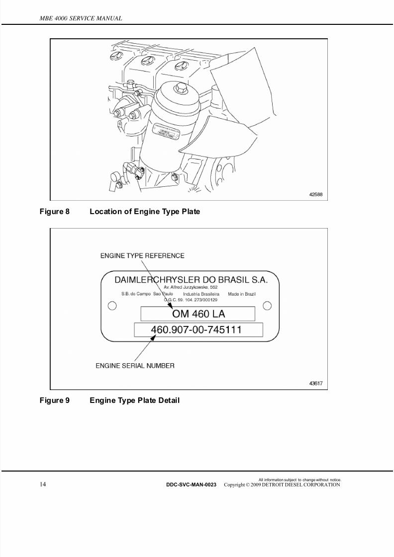
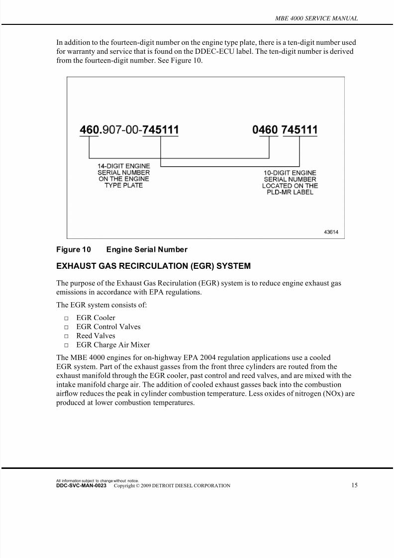
The engine model number and serial number are located on the engine type plate. It is located on
the oil filter housing on the right-hand side of the engine. See Figure 8. The engine type reference
and the complete engine serial number appear beside the name of the manufacturer. The engine
type reference, OM 460 LA is the production code. The engine serial number contains the typereference followed by a sequential manufacturing number. See Figure 9.
All information subject to change without notice.
DDC-SVC-MAN-0023 Copyright © 2009 DETROIT DIESEL CORPORATION 13
7/22/2019 Manual Mbe 4000 Taller
http://slidepdf.com/reader/full/manual-mbe-4000-taller 22/630
MBE 4000 SERVICE MANUAL
Figure 8 Location of Engine Type Plate
Figure 9 Engine Type Plate Detail
All information subject to change without notice.
14 DDC-SVC-MAN-0023 Copyright © 2009 DETROIT DIESEL CORPORATION
7/22/2019 Manual Mbe 4000 Taller
http://slidepdf.com/reader/full/manual-mbe-4000-taller 23/630
MBE 4000 SERVICE MANUAL
In addition to the fourteen-digit number on the engine type plate, there is a ten-digit number used
for warranty and service that is found on the DDEC-ECU label. The ten-digit number i s derived
from the fourteen-digit number. See Figure 10.
Figure 10 Engine Serial Number
EXHAUST GAS RECIRCULATION (EGR) SYSTEM
The purpose of the Exhaust Gas Recirulation (EGR) system is to reduce engine exhaust gas
emissions in accordance with EPA regulations.The EGR system consists of:
□ EGR Cooler
□ EGR Control Valves
□ Reed Valves
□ EGR Charge Air Mixer
The MBE 4000 engines for on-highway EPA 2004 regulation applications use a cooled
EGR system. Part of the exhaust gasses from the front three cylinders are routed from the
exhaust manifold through the EGR cooler, past control and reed valves, and are mixed with the
intake manifold charge air. The addition of cooled exhaust gasses back into the combustion
air flow reduces the peak in cylinder combustion temperature. Less oxides of nitrogen (NOx) are produced at lower combustion temperatures.
All information subject to change without notice.
DDC-SVC-MAN-0023 Copyright © 2009 DETROIT DIESEL CORPORATION 15

7/22/2019 Manual Mbe 4000 Taller
http://slidepdf.com/reader/full/manual-mbe-4000-taller 24/630
MBE 4000 SERVICE MANUAL
The recycled exhaust gasses are cooled before engine consumption in a tube and shell engine
water cooler. See Figure 11.
1. Engine 5. EGR Cooler
2. Intake Air 6. EGR Shutoff Valve
3. EGR Modulated Valve 7. Exhaust Air
4. Reed Valves
Figure 11 Air flow Diagram through Engine with EGR System
For an general view of the MBE 4000 engine with an EGR system, See Figure 12 for a right side
view and see Figure 13 for a left side view.
All information subject to change without notice.
16 DDC-SVC-MAN-0023 Copyright © 2009 DETROIT DIESEL CORPORATION

7/22/2019 Manual Mbe 4000 Taller
http://slidepdf.com/reader/full/manual-mbe-4000-taller 25/630
MBE 4000 SERVICE MANUAL
1. Oil Filter 8. EGR Cooler
2. Solenoid Valve (Wabco®) 9. Reed Valve Housing
3. Turbocharger 10. EGR Modulated Control Valve
4. EGR Gas Inlet P ipe (Hot P ipe) 11. EGR Mixer
5. Exhaust Manifold 12. EGR Gas Outlet Pipe (Cold P ipe)
6. EGR Shutoff Valve 13. Alternator
7. EGR Air Cylinder 14. Belt Tensioner
Figure 12 EGR Engine with EGR Components and Revised Parts (Right View)
All information subject to change without notice.
DDC-SVC-MAN-0023 Copyright © 2009 DETROIT DIESEL CORPORATION 17
7/22/2019 Manual Mbe 4000 Taller
http://slidepdf.com/reader/full/manual-mbe-4000-taller 26/630
MBE 4000 SERVICE MANUAL
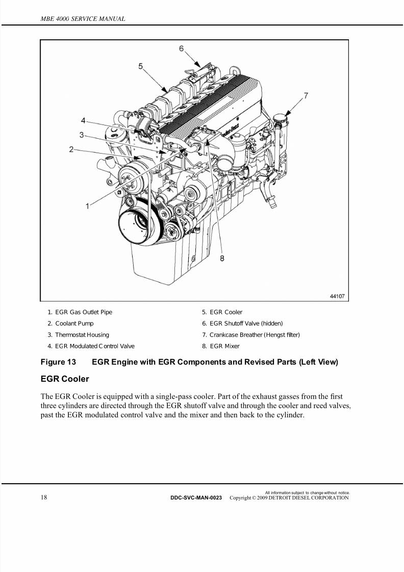
1. EGR Gas Outlet Pipe 5. EGR Cooler
2. Coolant Pump 6. EGR Shutoff Valve (hidden)
3. Thermostat Housing 7. Crankcase Breather (Hengst filter)
4. EGR Modulated C ontrol Valve 8. EGR Mixer
Figure 13 EGR Engine with EGR Components and Revised Parts (Left View)
EGR Cooler
The EGR Cooler is equipped with a single-pass cooler. Part of the exhaust gasses from the first
three cylinders are directed through the EGR shutoff valve and through the cooler and reed valves,
past the EGR modulated control valve and the mixer and then back to the cylinder.
All information subject to change without notice.
18 DDC-SVC-MAN-0023 Copyright © 2009 DETROIT DIESEL CORPORATION

7/22/2019 Manual Mbe 4000 Taller
http://slidepdf.com/reader/full/manual-mbe-4000-taller 27/630
MBE 4000 SERVICE MANUAL
EGR Control Valves
There are two EGR valves on the MBE 4000 EGR engine — the EGR shutoff valve and the
EGR modulated control valve. The EGR shutoff valve is a pneumatically driven butter fly valve,
located at the inlet of the EGR cooler. It closes when the exhaust flap or turbo-brake actuates,
avoiding exhaust gas flow and excessive pressure in the EGR cooler and r eed valves. The EGR
modulated control valve is an electronically actuated butter fl
y valve located after the EGR cooler and reed valves, controlled by the DDEC-ECU (formerly PLD-MR). This valve controls the
exhaust gas flow for the intake manifold.
Reed Valves
The reed valves work like a check valve, allowing flow of gas only in one direction, avoiding gas
back flow when the intake pressure is higher than exhaust gas pressure. As the average exhaust
pressure is lower than the intake pressure, the gas flow through the reed valves is possible due to
exhaust gas pressure peaks — peaks slightly higher than the intake air pressure, which occur as
the engine exhaust valves open. During this peak of pressure, the reed valves open and allow gas
flow to the EGR modulated valve and mixer.
EGR Mixer
The purpose of the mixer is to ensure good mixing of the cooled EGR gasses with filtered charge
air. Once the exhaust gasses are cooled and have completed their cycle through the EGR system,
they are released into the EGR mixer. The recycled exhaust gasses are combined with the charged
air and directed to the cylinders.
SAFETY INSTRUCTIONS AND PRECAUTIONS
The following safety measures are essential when working on the MBE 4000 engine.
To reduce the chance of personal injury and/or property damage, the following instructions
must be carefully observed:
□ Proper service and repair are important to the service technician and the safe, reliable
operation of the engine. If part re placement is necessary, the part must be replaced with
one of the same part number or with an equivalent part number. Do not use a replacement
part of lesser quality.
□ The service procedures recommended and described in this manual are effective methods
of performing repair. Some of these procedures require the use of specially designed tools.
Accordingly, anyone who intends to use a replacement part, procedure or tool that is not
recommended, must first determine that neither personal safety nor the safe operation of the
engine will be jeopardized by the replacement part, procedure or tool selected.
□ It is important to note that this manual contains various “Cautions” and “Notices” that must
be carefully observed in order to reduce the risk of personal injury during repair or the
possibility that improper repair may damage the engine or render it unsafe. It is also
important to understand that these “Cautions” and “Notices” are not exhaustive, because it
is impossible to warn personnel of the possible hazardous consequences that might result
from failure to follow these instructions.
All information subject to change without notice.
DDC-SVC-MAN-0023 Copyright © 2009 DETROIT DIESEL CORPORATION 19

7/22/2019 Manual Mbe 4000 Taller
http://slidepdf.com/reader/full/manual-mbe-4000-taller 28/630
MBE 4000 SERVICE MANUAL
Exhaust (Start/Run Engine)
Before starting and running an engine, adhere to the following safety precautions:
PERSONAL INJURYTo avoid injury before starting and running the engine,ensure the vehicle is parked on a level surface, parkingbrake is set, and the wheels are blocked.
PERSONAL INJURY
Diesel engine exhaust and some of its constituents areknown to the State of California to cause cancer, birth
defects, and other reproductive harm.□ Always start and operate an engine in a well ventilated
area.□ If operating an engine in an enclosed area, vent the
exhaust to the outside.□ Do not modify or tamper with the exhaust system or
emission control system.
Stands
Safety stands are required in conjunction with hydraulic jacks or hoists. Do not rely on either the
jack or the hoist to carry the load. When lifting an engine, ensure the lifting device is fastened
securely. Ensure the item to be lifted does not exceed the capacity of the lifting device.
PERSONAL INJURY
To avoid injury when removing or installing a heavy enginecomponent, ensure the component is properly supportedand securely attached to an adequate lifting device toprevent the component from falling.
Glasses
Select appropriate safety glasses for the job. It is especially important to wear safety glasses when
using tools such as hammers, chisels, pullers or punches.
All information subject to change without notice.
20 DDC-SVC-MAN-0023 Copyright © 2009 DETROIT DIESEL CORPORATION

7/22/2019 Manual Mbe 4000 Taller
http://slidepdf.com/reader/full/manual-mbe-4000-taller 29/630
MBE 4000 SERVICE MANUAL
PERSONAL INJURY
To avoid injury when working on or near an operatingengine, wear protective clothing, eye protection, and
hearing protection.
Work Place
Organize your work area and keep it clean. A fall could result in a serious injury. Eliminate
the possibility of a fall by:
□ Wiping up oil spills
□ Keeping tools and parts off the floor
After servicing or adjusting the engine:
□ Reinstall all safety devices, guards or shields
□ Ensure that all tools and servicing equipment are removed from the engine
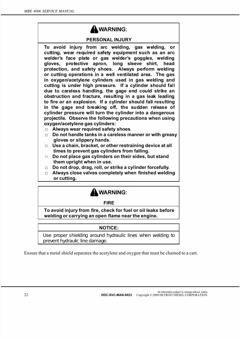
Welding
Wear welding goggles and gloves when welding or using an acetylene torch.
All information subject to change without notice.
DDC-SVC-MAN-0023 Copyright © 2009 DETROIT DIESEL CORPORATION 21
7/22/2019 Manual Mbe 4000 Taller
http://slidepdf.com/reader/full/manual-mbe-4000-taller 30/630
MBE 4000 SERVICE MANUAL
PERSONAL INJURY
To avoid injury from arc welding, gas welding, or cutting, wear required safety equipment such as an arc
welder’s face plate or gas welder’s goggles, weldinggloves, protective apron, long sleeve shirt, headprotection, and safety shoes. Always perform weldingor cutting operations in a well ventilated area. The gasin oxygen/acetylene cylinders used in gas welding andcutting is under high pressure. If a cylinder should falldue to careless handling, the gage end could strike anobstruction and fracture, resulting in a gas leak leadingto fire or an explosion. If a cylinder should fall resultingin the gage end breaking off, the sudden release of cylinder pressure will turn the cylinder into a dangerous
projectile. Observe the following precautions when usingoxygen/acetylene gas cylinders:□ Always wear required safety shoes.□ Do not handle tanks in a careless manner or with greasy
gloves or slippery hands.□ Use a chain, bracket, or other restraining device at all
times to prevent gas cylinders from falling.□ Do not place gas cylinders on their sides, but stand
them upright when in use.□ Do not drop, drag, roll, or strike a cylinder forcefully.□ Always close valves completely when finished welding
or cutting.
FIRE
To avoid injury from fire, check for fuel or oil leaks beforewelding or carrying an open flame near the engine.
NOTICE:
Use proper shielding around hydraulic lines when welding toprevent hydraulic line damage.
Ensure that a metal shield separates the acetylene and oxygen that must be chained to a cart.
All information subject to change without notice.
22 DDC-SVC-MAN-0023 Copyright © 2009 DETROIT DIESEL CORPORATION

7/22/2019 Manual Mbe 4000 Taller
http://slidepdf.com/reader/full/manual-mbe-4000-taller 31/630
MBE 4000 SERVICE MANUAL
Clothing
Safe work clothing fits and is in good repair. Work shoes are sturdy and rough-soled. Bare feet,
sandals or sneakers are not acceptable foot wear when adjusting and/or servicing an engine. Do
not wear the following when working on an engine:
PERSONAL INJURY
To avoid injury when working near or on an operatingengine, remove loose items of clothing and jewelry. Tieback or contain long hair that could be caught in anymoving part causing injury.
PERSONAL INJURYTo avoid injury when working on or near an operatingengine, wear protective clothing, eye protection, andhearing protection.
□ Rings
□ Wrist watches
□ Loose fitting clothing
Any of these items could catch on moving parts causing serious injury.
Power Tools
Do not use defective portable power tools.
ELECTRICAL SHOCK
To avoid injury from electrical shock, follow OEM furnishedoperating instructions prior to usage.
Check for frayed cords prior to using the tool. Be sure all electric tools are grounded. Defective
electrical equipment can cause severe injury. Improper use of electrical equipment can cause
severe injury.
Air
Recommendations regarding the use of compressed air are indicated throughout the manual.
All information subject to change without notice.
DDC-SVC-MAN-0023 Copyright © 2009 DETROIT DIESEL CORPORATION 23

7/22/2019 Manual Mbe 4000 Taller
http://slidepdf.com/reader/full/manual-mbe-4000-taller 32/630
MBE 4000 SERVICE MANUAL
EYE INJURY
To avoid injury from flying debris when using compressedair, wear adequate eye protection (face shield or safety
goggles) and do not exceed 276 kPa (40 psi) air pressure.
Fuel Lines
Remove fuel lines as an assembly. Do not remove fuel lines individually. Avoid getting fuel
injection lines mixed up.
Fluids and Pressure
Be extremely careful when dealing with fluids under pressure.
PERSONAL INJURY
To avoid injury from penetrating fluids, do not put your hands in front of fluid under pressure. Fluids under pressure can penetrate skin and clothing.
Fluids under pressure can have enough force to penetrate the skin. These fluids can infect a minor
cut or opening in the skin. If injured by escaping fluid, see a doctor at once. Serious infection
or reaction can result without immediate medical treatment.
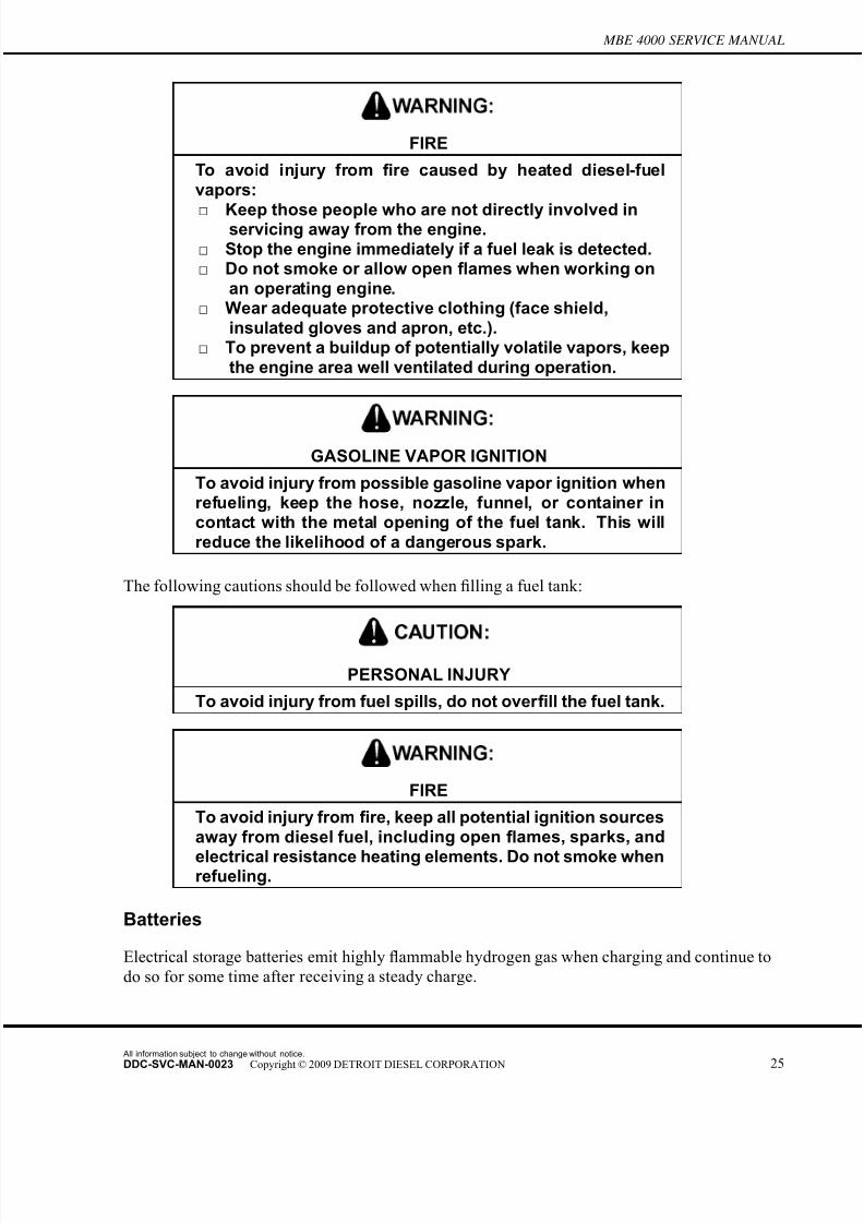
Fuel
Keep the hose and nozzle or the funnel and container in contact with the metal of the fuel tank
when refueling to avoid the possibility of an electric spark igniting the fuel.
All information subject to change without notice.
24 DDC-SVC-MAN-0023 Copyright © 2009 DETROIT DIESEL CORPORATION
7/22/2019 Manual Mbe 4000 Taller
http://slidepdf.com/reader/full/manual-mbe-4000-taller 33/630
MBE 4000 SERVICE MANUAL
FIRE
To avoid injury from fire caused by heated diesel-fuelvapors:
□ Keep those people who are not directly involved inservicing away from the engine.
□ Stop the engine immediately if a fuel leak is detected.□ Do not smoke or allow open flames when working on
an operating engine.□ Wear adequate protective clothing (face shield,
insulated gloves and apron, etc.).□ To prevent a buildup of potentially volatile vapors, keep
the engine area well ventilated during operation.
GASOLINE VAPOR IGNITION
To avoid injury from possible gasoline vapor ignition whenrefueling, keep the hose, nozzle, funnel, or container incontact with the metal opening of the fuel tank. This willreduce the likelihood of a dangerous spark.
The following cautions should be followed when filling a fuel tank:
PERSONAL INJURY
To avoid injury from fuel spills, do not over fill the fuel tank.
FIRE
To avoid injury from fire, keep all potential ignition sourcesaway from diesel fuel, including open flames, sparks, and
electrical resistance heating elements. Do not smoke whenrefueling.
Batteries
Electrical storage batteries emit highly flammable hydrogen gas when charging and continue to
do so for some time after receiving a steady charge.
All information subject to change without notice.
DDC-SVC-MAN-0023 Copyright © 2009 DETROIT DIESEL CORPORATION 25
7/22/2019 Manual Mbe 4000 Taller
http://slidepdf.com/reader/full/manual-mbe-4000-taller 34/630
MBE 4000 SERVICE MANUAL
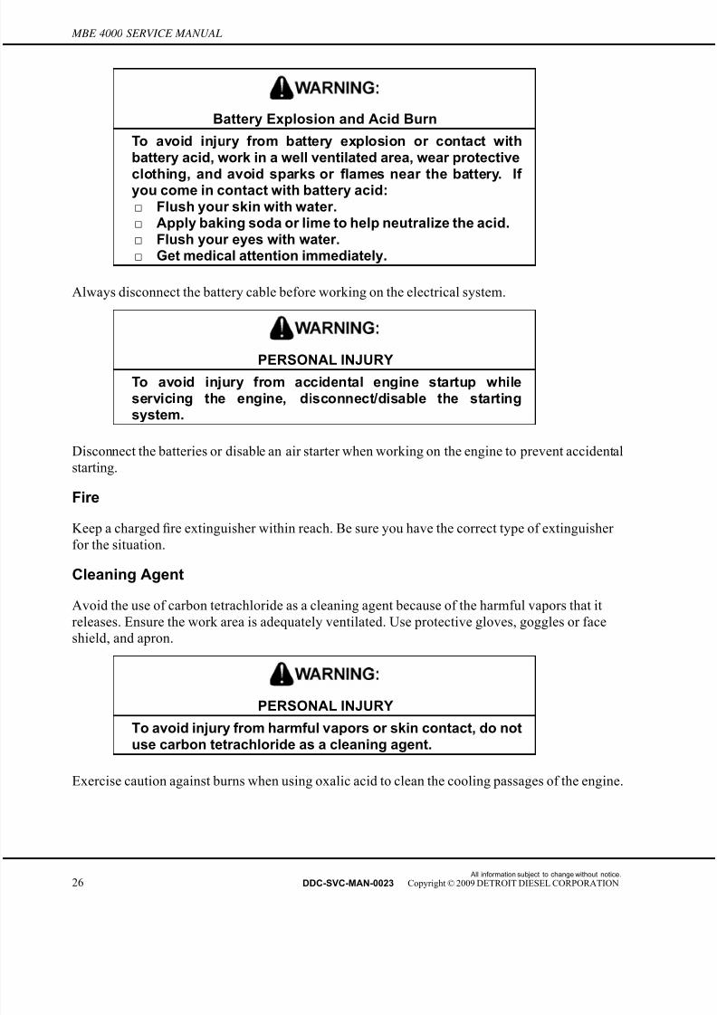
Battery Explosion and Acid Burn
To avoid injury from battery explosion or contact withbattery acid, work in a well ventilated area, wear protective
clothing, and avoid sparks or flames near the battery. If you come in contact with battery acid:□ Flush your skin with water.□ Apply baking soda or lime to help neutralize the acid.□ Flush your eyes with water.□ Get medical attention immediately.
Always disconnect the battery cable before working on the electrical system.
PERSONAL INJURY
To avoid injury from accidental engine startup whileservicing the engine, disconnect/disable the startingsystem.
Disconnect the batteries or disable an air starter when working on the engine to prevent accidental
starting.
Fire
Keep a chargedfi
re extinguisher within reach. Be sure you have the correct type of extinguisher for the situation.
Cleaning Agent
Avoid the use of carbon tetrachloride as a cleaning agent because of the harmful vapors that it
releases. Ensure the work area is adequately ventilated. Use protective gloves, goggles or face
shield, and apron.
PERSONAL INJURYTo avoid injury from harmful vapors or skin contact, do notuse carbon tetrachloride as a cleaning agent.
Exercise caution against burns when using oxalic acid to clean the cooling passages of the engine.
All information subject to change without notice.
26 DDC-SVC-MAN-0023 Copyright © 2009 DETROIT DIESEL CORPORATION
7/22/2019 Manual Mbe 4000 Taller
http://slidepdf.com/reader/full/manual-mbe-4000-taller 35/630
MBE 4000 SERVICE MANUAL
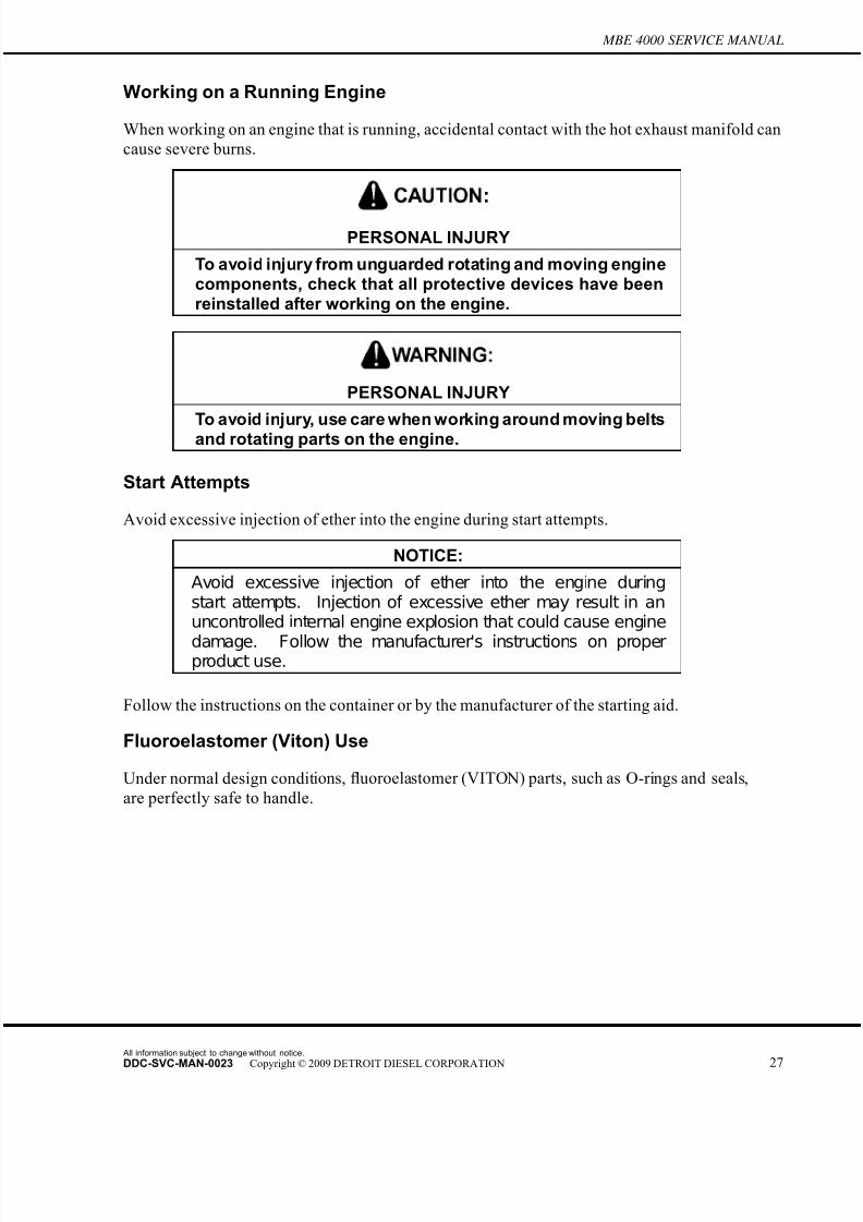
Working on a Running Engine
When working on an engine that is running, accidental contact with the hot exhaust manifold can
cause severe burns.
PERSONAL INJURY
To avoid injury from unguarded rotating and moving enginecomponents, check that all protective devices have beenreinstalled after working on the engine.
PERSONAL INJURY
To avoid injury, use care when working around moving beltsand rotating parts on the engine.
Start Attempts
Avoid excessive injection of ether into the engine during start attempts.
NOTICE:
Avoid excessive injection of ether into the engine duringstart attempts. Injection of excessive ether may result in anuncontrolled internal engine explosion that could cause engine
damage. Follow the manufacturer's instructions on properproduct use.
Follow the instructions on the container or by the manufacturer of the starting aid.
Fluoroelastomer (Viton) Use
Under normal design conditions, fluoroelastomer (VITON) parts, such as O-rings and seals,
are perfectly safe to handle.
All information subject to change without notice.
DDC-SVC-MAN-0023 Copyright © 2009 DETROIT DIESEL CORPORATION 27
7/22/2019 Manual Mbe 4000 Taller
http://slidepdf.com/reader/full/manual-mbe-4000-taller 36/630
MBE 4000 SERVICE MANUAL
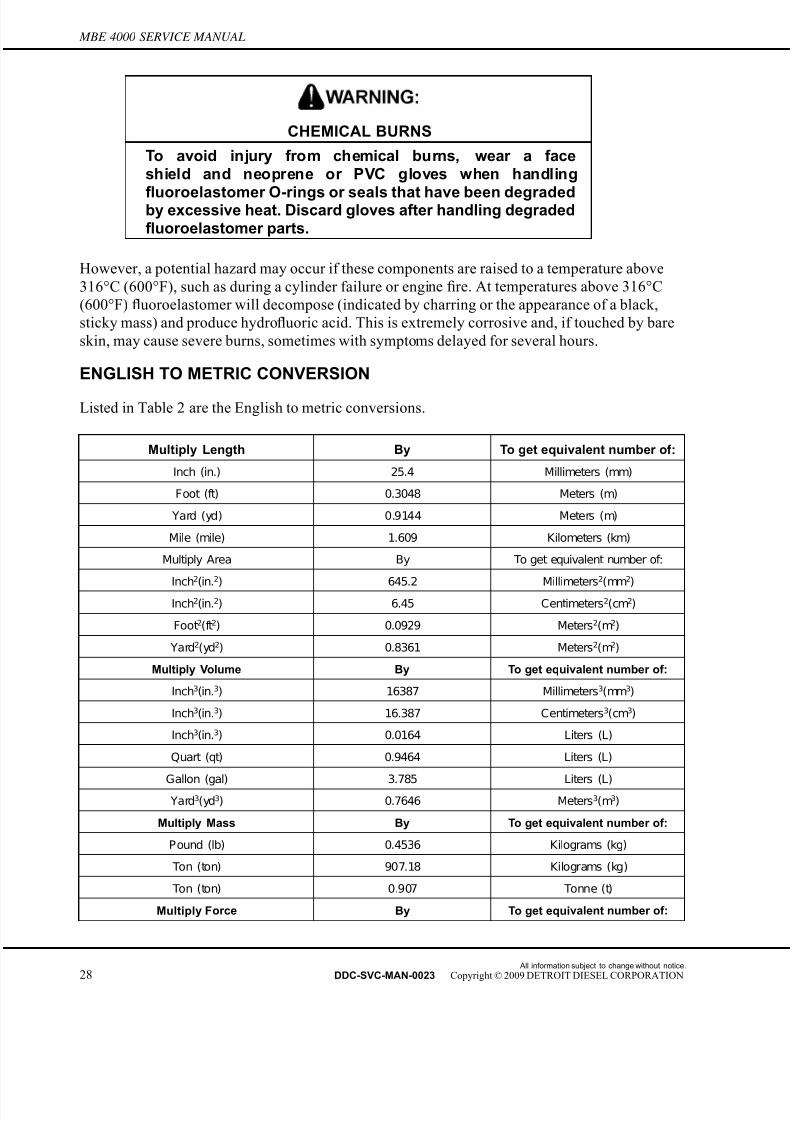
CHEMICAL BURNS
To avoid injury from chemical burns, wear a faceshield and neoprene or PVC gloves when handling
fluoroelastomer O-rings or seals that have been degradedby excessive heat. Discard gloves after handling degradedfluoroelastomer parts.
However, a potential hazard may occur if these components are raised to a temperature above
316°C (600°F), such as during a cylinder failure or engine fire. At temperatures above 316°C
(600°F) fluoroelastomer will decompose (indicated by charring or the appearance of a black,
sticky mass) and produce hydrofluoric acid. This is extremely corrosive and, if touched by bare
skin, may cause severe burns, sometimes with symptoms delayed for several hours.
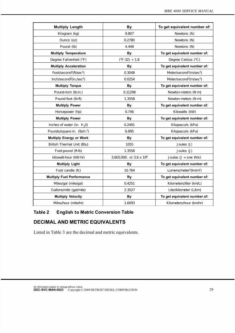
ENGLISH TO METRIC CONVERSION
Listed in Table 2 are the English to metric conversions.
Multiply Length By To get equivalent number of:
Inch (in.) 25.4 Millimeters (mm)
Foot (ft) 0.3048 Meters (m)
Yard (yd) 0.9144 Meters (m)
Mile (mile) 1.609 Kilometers (km)
Multiply Area By To get equivalent number of:
Inch2(in.2) 645.2 Millimeters2(mm2)
Inch2(in.2) 6.45 Centimeters2(cm2)
Foot2(ft2) 0.0929 Meters2(m2)
Yard2(yd2) 0.8361 Meters2(m2)
Multiply Volume By To get equivalent number of:
Inch3(in.3) 16387 Millimeters3(mm3)
Inch3(in.3) 16.387 Centimeters3(cm3)
Inch3(in.3) 0.0164 Liters (L)
Quart (qt) 0.9464 Liters (L)
Gallon (gal) 3.785 Liters (L)
Yard3(yd3) 0.7646 Meters3(m3)
Multiply Mass By To get equivalent number of:
Pound (lb) 0.4536 Kilograms (kg)
Ton (ton) 907.18 Kilograms (kg)
Ton (ton) 0.907 Tonne (t)
Multiply Force By To get equivalent number of:
All information subject to change without notice.
28 DDC-SVC-MAN-0023 Copyright © 2009 DETROIT DIESEL CORPORATION
7/22/2019 Manual Mbe 4000 Taller
http://slidepdf.com/reader/full/manual-mbe-4000-taller 37/630
MBE 4000 SERVICE MANUAL
Multiply Length By To get equivalent number of:
Kilogram (kg) 9.807 Newtons (N)
Ounce (oz) 0.2780 Newtons (N)
Pound (lb) 4.448 Newtons (N)
Multiply Temperature By To get equivalent number of:
Degree Fahrenheit (°F) (°F-32) ÷ 1.8 Degree Celsius (°C)
Multiply Acceleration By To get equivalent number of:
Foot/second2(ft/sec2) 0.3048 Meter/second2(m/sec2)
Inch/second2(in./sec2) 0.0254 Meter/second2(m/sec2)
Multiply Torque By To get equivalent number of:
Pound-inch (lb·in.) 0.11298 Newton-meters (N·m)
Pound-foot (lb·ft) 1.3558 Newton-meters (N·m)
Multiply Power By To get equivalent number of:
Horsepower (hp) 0.746 Kilowatts (kW)
Multiply Power By To get equivalent number of:
Inches of water (in. H20) 0.2491 Kilopascals (kPa)
Pounds/square in. (lb/in.2) 6.895 Kilopascals (kPa)
Multiply Energy or Work By To get equivalent number of:
British Thermal Unit (Btu) 1055 J oules (J )
Foot-pound (ft·lb) 1.3558 J oules (J )
kilowatt-hour (kW·hr) 3,600,000. or 3.6 x 10⁶ J oules (J = one W/s)
Multiply Light By To get equivalent number of:
Foot candle (fc) 10.764 Lumens/meter2(lm/m2)
Multiply Fuel Performance By To get equivalent number of:
Miles/gal (mile/gal) 0.4251 Kilometers/liter (km/L)
Gallons/mile (gal/mile) 2.3527 Liter/kilometer (L/km)
Multiply Velocity By To get equivalent number of:
Miles/hour (mile/hr) 1.6093 Kilometers/hour (km/hr)
Table 2 English to Metric Conversion Table
DECIMAL AND METRIC EQUIVALENTS
Listed in Table 3 are the decimal and metric equivalents.
All information subject to change without notice.
DDC-SVC-MAN-0023 Copyright © 2009 DETROIT DIESEL CORPORATION 29

7/22/2019 Manual Mbe 4000 Taller
http://slidepdf.com/reader/full/manual-mbe-4000-taller 38/630
MBE 4000 SERVICE MANUAL
Fractions of
an inch
Decimal (in.) Metric (mm) Fractions of
an inch
Decimal (in.) Metric (mm)
1/64 0.015625 0.39688 33/64 0.515625 13.09687
1/32 0.03125 0.79375 17/32 0.53125 13.49375
3/64 0.046875 1.19062 35/64 0.546875 13.89062
1/16 0.0625 1.58750 9/16 0.5625 14.28750
5/64 0.078125 1.98437 37/64 0.578125 14.68437
3/32 0.09375 2.38125 19/32 0.59375 15.08125
7/64 0.109375 2.77812 39/64 0.609375 15.47812
1/8 0.125 3.175 5/8 0.625 15.87500
9/64 0.140625 3.57187 41/64 0.640625 16.27187
5/32 0.15625 3.96875 21/32 0.65625 16.66875
11/64 0.171875 4.36562 43/64 0.671875 17.06562
3/16 0.1875 4.76250 11/16 0.6875 17.46250
13/64 0.203125 5.15937 45/64 0.703125 17.85937
7/32 0.21875 5.55625 23/32 0.71875 18.25625
15/64 0.234375 5.95312 47/64 0.734375 18.65312
1/4 0.250 6.35000 3/4 0.750 19.05000
17/64 0.265625 6.74687 49/64 0.765625 19.44687
9/32 0.28125 7.14375 25/32 0.78125 19.84375
19/64 0.296875 7.54062 51/64 0.796875 20.24062
5/16 0.3125 7.93750 13/16 0.8125 20.63750
21/64 0.328125 8.33437 53/64 0.828125 21.03437
11/32 0.34375 8.73125 27/32 0.84375 21.43125
23/64 0.359375 9.12812 55/64 0.859375 21.82812
3/8 0.375 9.52500 7/8 0.875 22.22500
25/64 0.390625 9.92187 57/64 0.890625 22.62187
13/32 0.40625 10.31875 29/32 0.90625 23.01875
27/64 0.421875 10.71562 59/64 0.921875 23.41562
7/16 0.4375 11.11250 15/16 0.9375 23.81250
29/64 0.453125 11.50937 61/64 0.953125 24.20937
15/32 0.46875 11.90625 31/32 0.96875 24.60625
31/64 0.484375 12.30312 63/64 0.984375 25.00312
1/2 0.500 12.70000 1 1.00 25.40000
Table 3 Conversion Chart-Customary and Metric Units
All information subject to change without notice.
30 DDC-SVC-MAN-0023 Copyright © 2009 DETROIT DIESEL CORPORATION
7/22/2019 Manual Mbe 4000 Taller
http://slidepdf.com/reader/full/manual-mbe-4000-taller 39/630
MBE 4000 SERVICE MANUAL
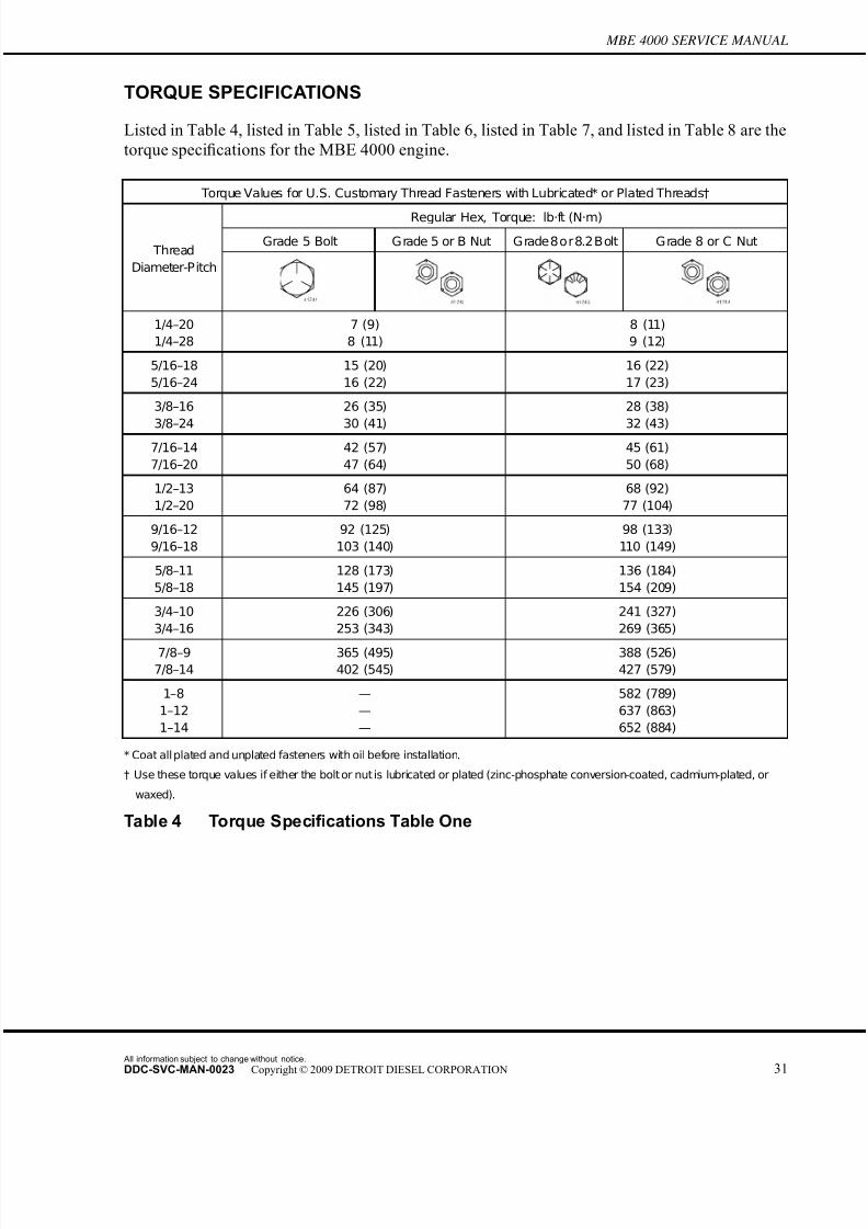
TORQUE SPECIFICATIONS
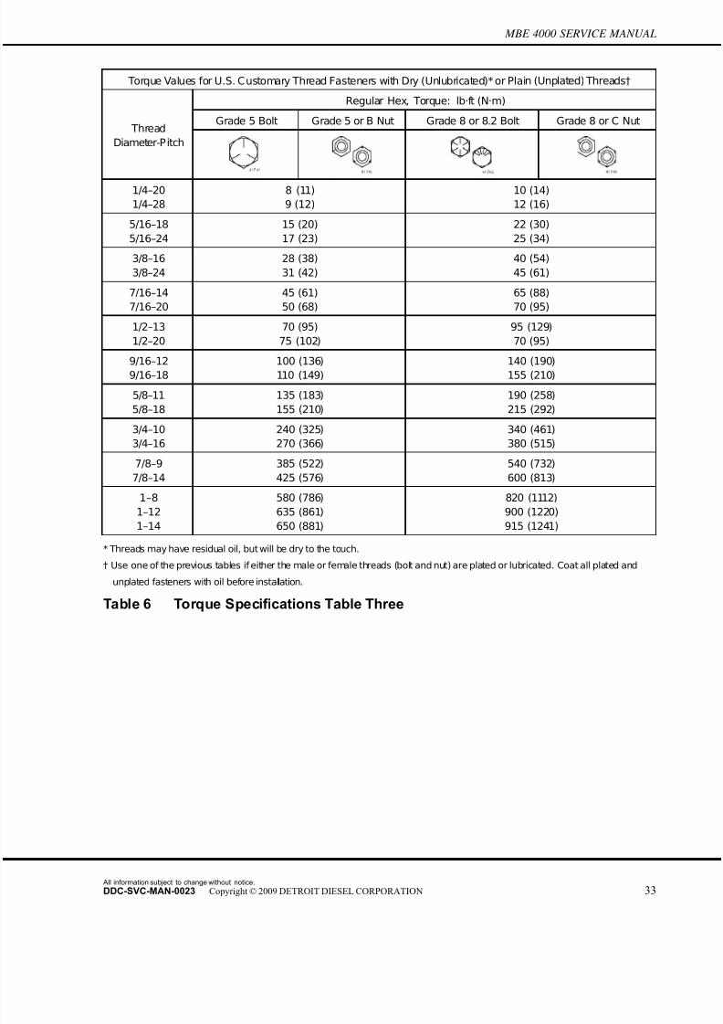
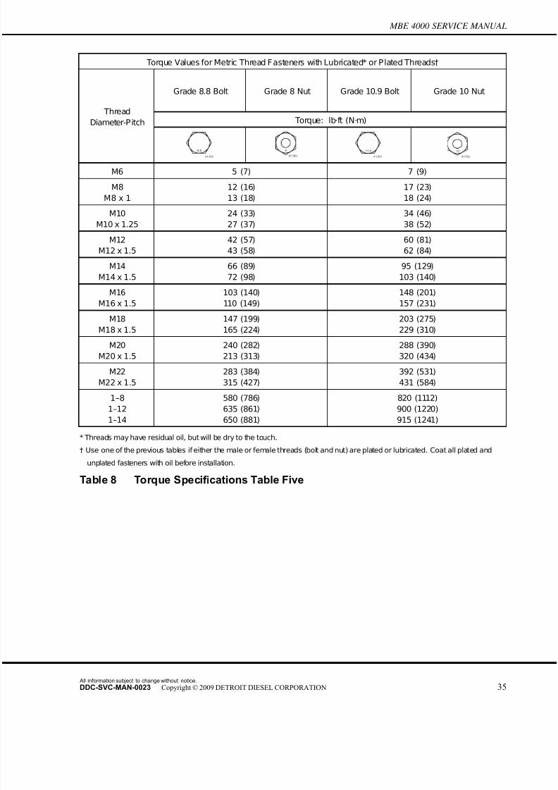
Listed in Table 4, listed in Table 5, listed in Table 6, listed in Table 7, and listed in Table 8 are the
torque specifications for the MBE 4000 engine.
Torque Values for U.S. Customary Thread Fasteners with Lubricated* or Plated Threads†
Regular Hex, Torque: lb·ft (N·m)
Grade 5 Bolt Grade 5 or B Nut Grade8or8.2Bolt Grade 8 or C Nut Thread
Diameter-Pitch
1/4–20
1/4–28
7 (9)
8 (11)
8 (11)
9 (12)
5/16–18
5/16–24
15 (20)
16 (22)
16 (22)
17 (23)
3/8–16
3/8–24
26 (35)
30 (41)
28 (38)
32 (43)
7/16–14
7/16–20
42 (57)
47 (64)
45 (61)
50 (68)
1/2–13
1/2–20
64 (87)
72 (98)
68 (92)
77 (104)
9/16–12
9/16–18
92 (125)
103 (140)
98 (133)
110 (149)
5/8–11
5/8–18
128 (173)
145 (197)
136 (184)
154 (209)
3/4–10
3/4–16
226 (306)
253 (343)
241 (327)
269 (365)
7/8–9
7/8–14
365 (495)
402 (545)
388 (526)
427 (579)
1–8
1–12
1–14
—
—
—
582 (789)
637 (863)
652 (884)
* Coat all plated and unplated fasteners with oil before installation.
† Use these torque values if either the bolt or nut is lubricated or plated (zinc-phosphate conversion-coated, cadmium-plated, or
waxed).
Table 4 Torque Specifications Table One
All information subject to change without notice.
DDC-SVC-MAN-0023 Copyright © 2009 DETROIT DIESEL CORPORATION 31

7/22/2019 Manual Mbe 4000 Taller
http://slidepdf.com/reader/full/manual-mbe-4000-taller 40/630
MBE 4000 SERVICE MANUAL
Torque Values for U.S. Customary Thread Fasteners with Lubricated* or Plated Threads†
Flanged, Torque: lb·ft (N·m)
Grade 5 Bolt Grade B Nut Grade 8 or C Nut Grade G Nut Thread
Diameter-Pitch
1/4–20
1/4–28
6 (8)
7 (9)
10 (14)
12 (16)
5/16–18
5/16–24
13 (18)
14 (19)
21 (28)
23 (31)
3/8–16
3/8–24
23 (31)
25 (34)
37 (50)
42 (57)
7/16–14
7/16–20
35 (47)
40 (54)
60 (81)
66 (89)
1/2–13
1/2–20
55 (75)
65 (88)
91 (123)
102 (138)
9/16–12
9/16–18
80 (108)
90 (122)
130 (176)
146 (198)
5/8–11
5/8–18
110 (149)
130 (176)
180 (244)
204 (277)
3/4–10
3/4–16
200 (271)
220 (298)
320 (434)
357 (484)
7/8–9
7/8–14
320 (434)
350 (475)
515 (698)
568 (770)
1–8
1–12
1–14
—
—
—
—
—
—
* Coat all plated and unplated fasteners with oil before installation.
† Use these torque values if either the bolt or nut is lubricated or plated (zinc-phosphate conversion-coated, cadmium-plated, or
waxed).
Table 5 Torque Specifications Table Two
All information subject to change without notice.
32 DDC-SVC-MAN-0023 Copyright © 2009 DETROIT DIESEL CORPORATION
7/22/2019 Manual Mbe 4000 Taller
http://slidepdf.com/reader/full/manual-mbe-4000-taller 41/630
MBE 4000 SERVICE MANUAL
Torque Values for U.S. Customary Thread Fasteners with Dry (Unlubricated)* or Plain (Unplated) Threads†
Regular Hex, Torque: lb·ft (N·m)
Grade 5 Bolt Grade 5 or B Nut Grade 8 or 8.2 Bolt Grade 8 or C Nut Thread
Diameter-Pitch
1/4–20
1/4–28
8 (11)
9 (12)
10 (14)
12 (16)
5/16–18
5/16–24
15 (20)
17 (23)
22 (30)
25 (34)
3/8–16
3/8–24
28 (38)
31 (42)
40 (54)
45 (61)
7/16–14
7/16–20
45 (61)
50 (68)
65 (88)
70 (95)
1/2–13
1/2–20
70 (95)
75 (102)
95 (129)
70 (95)
9/16–129/16–18
100 (136)110 (149)
140 (190)155 (210)
5/8–11
5/8–18
135 (183)
155 (210)
190 (258)
215 (292)
3/4–10
3/4–16
240 (325)
270 (366)
340 (461)
380 (515)
7/8–9
7/8–14
385 (522)
425 (576)
540 (732)
600 (813)
1–8
1–12
1–14
580 (786)
635 (861)
650 (881)
820 (1112)
900 (1220)
915 (1241)
* Threads may have residual oil, but will be dry to the touch.
† Use one of the previous tables if either the male or female threads (bolt and nut) are plated or lubricated. Coat all plated and
unplated fasteners with oil before installation.
Table 6 Torque Specifications Table Three
All information subject to change without notice.
DDC-SVC-MAN-0023 Copyright © 2009 DETROIT DIESEL CORPORATION 33

7/22/2019 Manual Mbe 4000 Taller
http://slidepdf.com/reader/full/manual-mbe-4000-taller 42/630
MBE 4000 SERVICE MANUAL
Torque Values for U.S. Customary Thread Fasteners with Dry (Unlubricated)* or Plain (Inplated) Threads†
Flanged, Torque: lb·ft (N·m)
Grade 8 or C Nut Grade G Nut Thread
Diameter-P itch
1/4–20
1/4–28
—
—
5/16–18
5/16–24
22 (30)
—
3/8–16
3/8–24
40 (54)
—
7/16–14
7/16–20
65 (88)
—
1/2–13
1/2–20
95 (129)
—
9/16–12
9/16–18
140 (190)
—
5/8–11
5/8–18
190 (258)
—
3/4–10
3/4–16
340 (461)
—
7/8–9
7/8–14
—
—
1–8
1–12
1–14
—
—
—
* Threads may have residual oil, but will be dry to the touch.
† Use one of the previous tables if either the male or female threads (bolt and nut) are plated or lubricated. Coat all plated and
unplated fasteners with oil before installation.
Table 7 Torque Specifications Table Four
All information subject to change without notice.
34 DDC-SVC-MAN-0023 Copyright © 2009 DETROIT DIESEL CORPORATION
7/22/2019 Manual Mbe 4000 Taller
http://slidepdf.com/reader/full/manual-mbe-4000-taller 43/630
MBE 4000 SERVICE MANUAL
Torque Values for Metric Thread F asteners with Lubricated* or Plated Threads†
Grade 8.8 Bolt Grade 8 Nut Grade 10.9 Bolt Grade 10 Nut
Torque: lb·ft (N·m) Thread
Diameter-Pitch
M6 5 (7) 7 (9)
M8
M8 x 1
12 (16)
13 (18)
17 (23)
18 (24)
M10
M10 x 1.25
24 (33)
27 (37)
34 (46)
38 (52)
M12
M12 x 1.5
42 (57)
43 (58)
60 (81)
62 (84)
M14
M14 x 1.5
66 (89)
72 (98)
95 (129)
103 (140)
M16
M16 x 1.5
103 (140)
110 (149)
148 (201)
157 (231)
M18
M18 x 1.5
147 (199)
165 (224)
203 (275)
229 (310)
M20
M20 x 1.5
240 (282)
213 (313)
288 (390)
320 (434)
M22
M22 x 1.5
283 (384)
315 (427)
392 (531)
431 (584)
1–8
1–12
1–14
580 (786)
635 (861)
650 (881)
820 (1112)
900 (1220)
915 (1241)
* Threads may have residual oil, but will be dry to the touch.
† Use one of the previous tables if either the male or female threads (bolt and nut) are plated or lubricated. Coat all plated and
unplated fasteners with oil before installation.
Table 8 Torque Specifications Table Five
All information subject to change without notice.
DDC-SVC-MAN-0023 Copyright © 2009 DETROIT DIESEL CORPORATION 35

7/22/2019 Manual Mbe 4000 Taller
http://slidepdf.com/reader/full/manual-mbe-4000-taller 44/630
MBE 4000 SERVICE MANUAL
All information subject to change without notice.
36 DDC-SVC-MAN-0023 Copyright © 2009 DETROIT DIESEL CORPORATION
7/22/2019 Manual Mbe 4000 Taller
http://slidepdf.com/reader/full/manual-mbe-4000-taller 45/630
1 ENGINE
Section Page
1.1 CYLINDER HEAD COVER ...................................................................... 1-3
1.2 CY LINDER HEAD .................................................................................... 1-4
1.3 CY LINDER BLOCK .................................................................................. 1-22
1.4 EGR CYLINDER HEAD AND BLOCK ..................................................... 1-44
1.5 EGR FRONT AND REAR LIFTER BRACKETS ....................................... 1-47
1.6 ENGINE BRAKE ...................................................................................... 1-49
1.7 FRONT RADIAL SEAL ............................................................................. 1-56
1.8 REAR RADIAL SEAL ............................................................................... 1-60
1.9 CRANKSHAFT SEAL WEAR SLEEVE .................................................... 1-63
1.10 CRANKSHAFT ASSEMBLY ..................................................................... 1-681.11 FRONT COVER HOUSING ..................................................................... 1-91
1.12 CRANKSHAFT VIBRATION DAMPER .................................................... 1-93
1.13 FLYWHEEL .............................................................................................. 1-95
1.14 RING GEAR ............................................................................................. 1-104
1.15 PILOT BEARING ...................................................................................... 1-108
1.16 ENGINE BARRING TOOL ....................................................................... 1-112
1.17 FLYWHEEL HOUSING ............................................................................ 1-114
1.18 PISTON, PISTON RING, AND CONNECTING ROD ............................... 1-116
1.19 EGR PISTON, PISTON RING, AND CONNECTING ROD ...................... 1-140
1.20 VALVES .................................................................................................... 1-143
1.21 EGR VALVES ........................................................................................... 1-162
1.22 ROCKER ARM ......................................................................................... 1-167

7/22/2019 Manual Mbe 4000 Taller
http://slidepdf.com/reader/full/manual-mbe-4000-taller 46/630
1.23 CAMSHAFT AND CAMSHAFT POSITION SENSOR .............................. 1-171
1.24 EGR CAMSHAFT ..................................................................................... 1-181
1.A ADDITIONAL INFORMATION .................................................................. 1-183
All information subject to change without notice.
1-2 DDC-SVC-MAN-0023 Copyright © 2009 DETROIT DIESEL CORPORATION
7/22/2019 Manual Mbe 4000 Taller
http://slidepdf.com/reader/full/manual-mbe-4000-taller 47/630
MBE 4000 SERVICE MANUAL
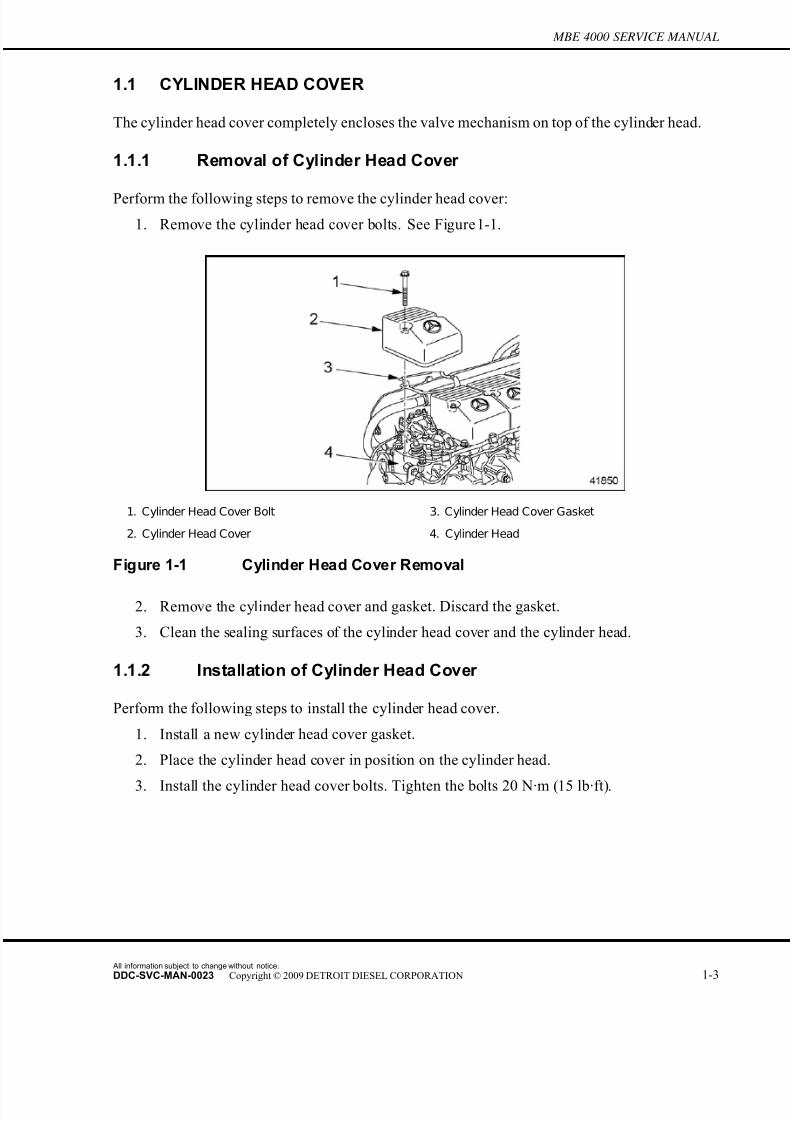
1.1 CYLINDER HEAD COVER
The cylinder head cover completely encloses the valve mechanism on top of the cylind er head.
1.1.1 Removal of Cylinder Head Cover
Perform the following steps to remove the cylinder head cover:
1. Remove the cylinder head cover bolts. See Figure 1-1.
1. Cylinder Head Cover Bolt 3. Cylinder Head Cover Gasket
2. Cylinder Head Cover 4. Cylinder Head
Figure 1-1 Cylinder Head Cover Removal
2. Remove the cylinder head cover and gasket. Discard the gasket.
3. Clean the sealing surfaces of the cylinder head cover and the cylinder head.
1.1.2 Installation of Cylinder Head Cover
Perform the following steps to install the cylinder head cover.
1. Install a new cylinder head cover gasket.
2. Place the cylinder head cover in position on the cylinder head.
3. Install the cylinder head cover bolts. Tighten the bolts 20 N·m (15 lb·ft).
All information subject to change without notice.
DDC-SVC-MAN-0023 Copyright © 2009 DETROIT DIESEL CORPORATION 1-3
7/22/2019 Manual Mbe 4000 Taller
http://slidepdf.com/reader/full/manual-mbe-4000-taller 48/630
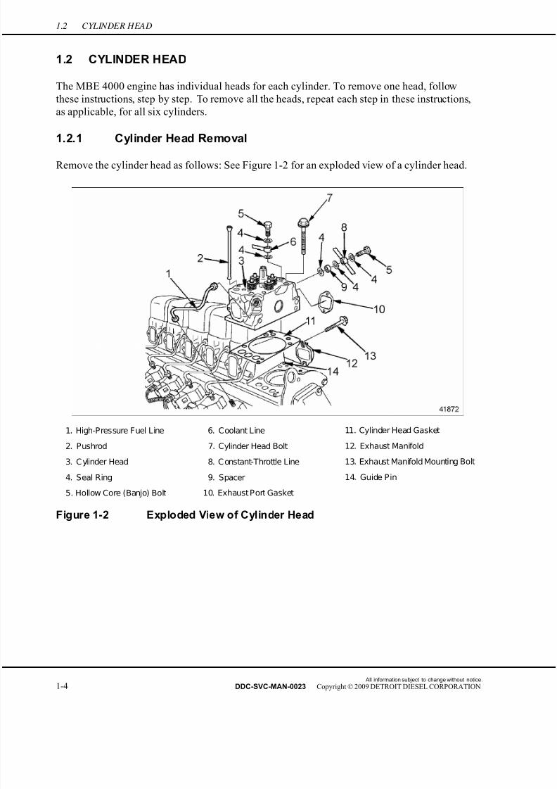
1.2 CYLINDER HEAD
1.2 CYLINDER HEAD
The MBE 4000 engine has individual heads for each cylinder. To remove one head, follo w
these instructions, step by step. To remove all the heads, repeat each step in these instructions,
as applicable, for all six cylinders.
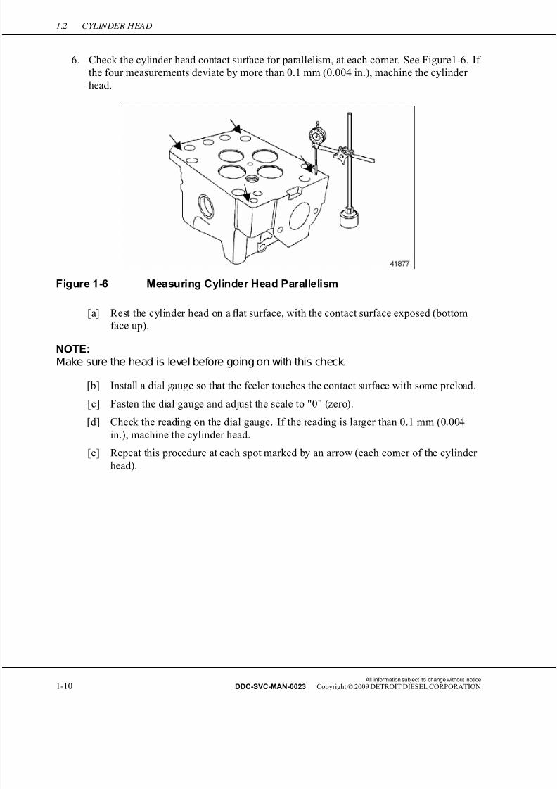
1.2.1 Cylinder Head Removal
Remove the cylinder head as follows: See Figure 1-2 for an exploded view of a cylinder head.
1. High-Pressure Fuel Line 6. Coolant Line 11. Cylinder Head Gasket
2. Pushrod 7. Cylinder Head Bolt 12. Exhaust Manifold
3. C ylinder Head 8. C onstant-Throttle Line 13. Exhaust Manifold Mounting Bolt
4. Seal Ring 9. Spacer 14. Guide Pin
5. Hollow Core (Banjo) Bolt 10. Exhaust Port Gasket
Figure 1-2 Exploded View of Cylinder Head
All information subject to change without notice.
1-4 DDC-SVC-MAN-0023 Copyright © 2009 DETROIT DIESEL CORPORATION
7/22/2019 Manual Mbe 4000 Taller
http://slidepdf.com/reader/full/manual-mbe-4000-taller 49/630
MBE 4000 SERVICE MANUAL
HOT COOLANT
To avoid scalding from the expulsion of hot coolant, never remove the cooling system pressure cap while the engine
is at operating temperature. Wear adequate protectiveclothing (face shield, rubber gloves, apron, and boots).Remove the cap slowly to relieve pressure.
1. Drain the coolant from the radiator.
All information subject to change without notice.
DDC-SVC-MAN-0023 Copyright © 2009 DETROIT DIESEL CORPORATION 1-5

7/22/2019 Manual Mbe 4000 Taller
http://slidepdf.com/reader/full/manual-mbe-4000-taller 50/630
1.2 CYLINDER HEAD
NOTE:Clean the cylinder head cover before removing it.
2. Remove the cylinder head cover. Refer to section 1.1.1.
3. Remove the rocker arm assembly. Mark the valve bridges and pushrods in order of
removal. Refer to section 1.22.1.
4. Remove the engine trim covers to gain access to the high-pressure fuel lines.
5. Remove the charge-air intake manifold.
NOTICE:
Do not move the thrust bolt during the removal of thehigh-pressure fuel line, because there is danger of causinga change in the position of the transfer-tube. If the position of the transfer-tube is changed, engine damage could result.
6. Using two wrenches, loosen the high-pressure fuel line at the transfer-tube fitting.
See Figure 1-3.
1. Pump-End Fitting 3. Thrust Bolt
2. High-Pressure In jector Line 4. Transfer-Tube Fitting
Figure 1-3 High-Pressure Fuel Line Fittings
[a] Using a paint pen, mark the location of the thrust bolt.
[b] Place one wrench on the thrust bolt to secure the transfer-tube. Place the other
wrench on the high-pressure line fitting.
[c] Turn the wr ench on the high-pressure line fitting while holding the other wrench
on the thrust bolt.
7. Remove the high-pressure fuel line from the transfer-tube and unit pump.
All information subject to change without notice.
1-6 DDC-SVC-MAN-0023 Copyright © 2009 DETROIT DIESEL CORPORATION

7/22/2019 Manual Mbe 4000 Taller
http://slidepdf.com/reader/full/manual-mbe-4000-taller 51/630
MBE 4000 SERVICE MANUAL
8. To prevent any dirt from entering, cover the openings in the unit pump and the
transfer-tube.
9. Remove the exhaust manifold bolts.
NOTE:If removing one or two cylinder heads, loosen the bolts on the rest of the exhaust
manifold.
10. Pull the exhaust manifold away from the engine, towards the frame rail. Remove all
the gaskets.
NOTE:If removing all cylinder heads, remove the exhaust manifold from the engine.
11. Remove the fuel return line from the cylinder head. Discard the seal rings. See Figure 1-4.
12. Disconnect the constant-throttle line from the cylinder head. Discard the seal rings.
See Figure 1-2.
13. Disconnect the coolant line from the cylinder head. See Figure 1-4.
14. Using the head bolt impact socket (J-45389), loosen the cylinder head bolts. When all the
bolts are loose, remove the bolts from the cylinder head. See Figure 1-4.
1. F uel R eturn Line C onnection 2. C oolant Line connection
Figure 1-4 Loosening the Head Bolts
NOTICE:
Do not place the head mating surface down on a flat surface. This would damage the injector nozzles, which protrude slightly.
15. Remove the cylinder head and set it on wooden blocks or on its side.
16. Remove the head gasket.
All information subject to change without notice.
DDC-SVC-MAN-0023 Copyright © 2009 DETROIT DIESEL CORPORATION 1-7
7/22/2019 Manual Mbe 4000 Taller
http://slidepdf.com/reader/full/manual-mbe-4000-taller 52/630
1.2 CYLINDER HEAD
17. Thoroughly clean the cylinder head, both contact surfaces (head and block), and surfaces
inside the cylinder of excess oil, grime, and paint chips.
18. With a straightedge, check the cylinder head surface for warpage. Refer to section 1.2.1.1.
Listed in Table 1-1 are warpage limits.
Description Limit: mm (in.)
Over a length of 150 mm (6 in.) 0.015 (0.0006)
Table 1-1 Head Warpage Limits
19. Check the cylinder liner protrusion from the cylinder block. Listed in Table 1-2 are the
specifications. Refer to section 1.3.1.2.
Description Value: mm (in.)
Cylinder Liner Protrusion from block 0.230-0.330 mm (0.0090-0.0130 in.)
Difference between the four measuring points Max.: 0.02 mm (0.0007 in.)
Table 1-2 Specifications for Measuring Cylinder Liner Protrusion
20. Inspect the cylinder head for cracks or signs of damage. Replace if necessary.
1.2.1.1 Cylinder Head Inspection and Machining
Inspection
1. Remove the cylinder head.
2. Remove the nozzle holder.
3. Remove the intake and exhaust valves. Refer to section 1.20.5.
4. Remove the constant-throttle valve. Refer to section 1.6.1.
All information subject to change without notice.
1-8 DDC-SVC-MAN-0023 Copyright © 2009 DETROIT DIESEL CORPORATION

7/22/2019 Manual Mbe 4000 Taller
http://slidepdf.com/reader/full/manual-mbe-4000-taller 53/630
MBE 4000 SERVICE MANUAL
5. Inspect the contact surface (bottom face) of the cylinder head for warpage, both lengthwise
and diagonally. See Figure 1-5. If the gap is larger than 0.015 mm (0.0006 in.), machine
the cylinder head.
1. Contact Surface 2. Straightedge
Figure 1-5 Measuring Cylinder Head Warpage
[a] Place a straightedge lengthwise across the cylinder head contact surface (bottom
face).
[b] If there is a gap between the lower edge of the straightedge and the contact surface
of the cylinder head that is large enough to let light through, insert a feeler gauge
into the gap.
[c] Measure the amount of warpage with the feeler gauge and compare it to the valuelisted in Table 1-3. If the gap is larger than 0.015 mm (0.0006 in.), machine the
cylinder head.
What To Measure How To Measure Specification: mm (in.)
Maximum Permissible Warpage
of Head Mating SurfaceLengthwise and Diagonally 0.015 (0.0006)
Maximum Permissible Parallelism
Deviation of Head Mating SurfaceAt Each of the F our Corners 0.1 (0.004)
When New 113.85-114.15 (4.482-4.494)Overall Height of Cylinder Head
After Machining 113.5 (4.46)
Table 1-3 Cylinder Head Specifications
[d] Place the straightedge diagonally across the cylinder head. Repeat the procedure
above.
All information subject to change without notice.
DDC-SVC-MAN-0023 Copyright © 2009 DETROIT DIESEL CORPORATION 1-9
7/22/2019 Manual Mbe 4000 Taller
http://slidepdf.com/reader/full/manual-mbe-4000-taller 54/630
1.2 CYLINDER HEAD
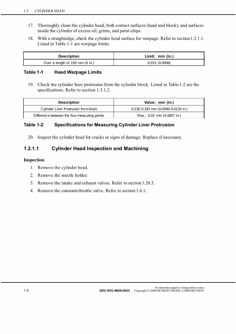
6. Check the cylinder head contact surface for parallelism, at each corner. See Figure 1-6. If
the four measurements deviate by more than 0.1 mm (0.004 in.), machine the cylinder
head.
Figure 1-6 Measuring Cylinder Head Parallelism
[a] Rest the cylinder head on a flat surface, with the contact surface exposed (bottom
face up).
NOTE:Make sure the head is level before going on with this check.
[b] Install a dial gauge so that the feeler touches the contact surface with some preload.
[c] Fasten the dial gauge and adjust the scale to "0" (zero).
[d] Check the reading on the dial gauge. If the reading is larger than 0.1 mm (0.004
in.), machine the cylinder head.
[e] Repeat this procedure at each spot marked by an arrow (each corner of the cylinder
head).
All information subject to change without notice.
1-10 DDC-SVC-MAN-0023 Copyright © 2009 DETROIT DIESEL CORPORATION

7/22/2019 Manual Mbe 4000 Taller
http://slidepdf.com/reader/full/manual-mbe-4000-taller 55/630
MBE 4000 SERVICE MANUAL
7. Measure the overall height of the cylinder head. See Figure 1-7. Replace the head if
below the minimum height. If above the maximum height, machine the head down to
the maximum height listed in Table 1-3.
1. Cylinder Head 2. Exhaust Valve 3. Intake Valve
Figure 1-7 Measuring Cylinder Head Height
Machining
1. Machine the contact surface of the cylinder head, to correct any problems found during
inspection.
[a] If rejected for warpage, check warpage again until it is within specifications.
[b] If rejected for lack of parallelism, check parallelism again until it is within
specifications.
2. After machining, check again the overall height of the cylinder head.
3. Install the constant-throttle valve. Refer to section 1.6.2.
4. Install the intake and exhaust valves. Refer to section 1.20.6.
5. Install the nozzle holder.
6. Install the cylinder head. Refer to section 1.2.2.
1.2.1.2 Cylinder Head Leak Testing
Perform the following steps to conduct a cylinder head leak test to see if the cylinder head is
leaking coolant.
1. Remove the exhaust brake compressed-air line from the exhaust brake cylinder.
2. Remove the v-band clamp connecting the exhaust pipe to the brake valve housing.
3. Remove the turbocharger.
All information subject to change without notice.
DDC-SVC-MAN-0023 Copyright © 2009 DETROIT DIESEL CORPORATION 1-11
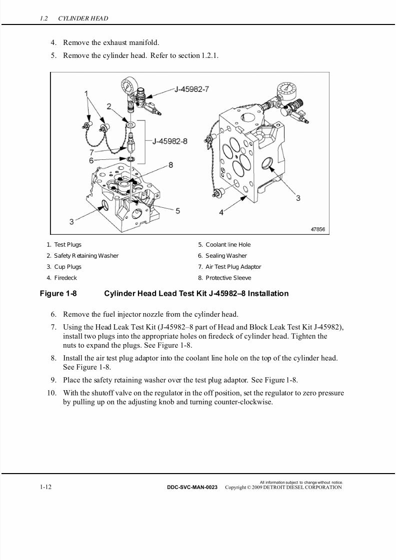
7/22/2019 Manual Mbe 4000 Taller
http://slidepdf.com/reader/full/manual-mbe-4000-taller 56/630
1.2 CYLINDER HEAD
4. Remove the exhaust manifold.
5. Remove the cylinder head. Refer to section 1.2.1.
1. Test Plugs 5. Coolant line Hole
2. Safety R etaining Washer 6. Sealing Washer
3. Cup Plugs 7. Air Test Plug Adaptor
4. Firedeck 8. Protective Sleeve
Figure 1-8 Cylinder Head Lead Test Kit J-45982–8 Installation
6. Remove the fuel injector nozzle from the cylinder head.
7. Using the Head Leak Test Kit (J-45982–8 part of Head and Block Leak Test Kit J-45982),
install two plugs into the appropriate holes on firedeck of cylinder head. Tighten the
nuts to expand the plugs. See Figure 1-8.
8. Install the air test plug adaptor into the coolant line hole on the top of the cylinder head.
See Figure 1-8.
9. Place the safety retaining washer over the test plug adaptor. See Figure 1-8.
10. With the shutoff valve on the regulator in the off position, set the regulator to zero pressure by pulling up on the adjusting knob and turning counter-clockwise.
All information subject to change without notice.
1-12 DDC-SVC-MAN-0023 Copyright © 2009 DETROIT DIESEL CORPORATION
7/22/2019 Manual Mbe 4000 Taller
http://slidepdf.com/reader/full/manual-mbe-4000-taller 57/630
MBE 4000 SERVICE MANUAL
EYE INJURY
To avoid injury from flying debris when using compressedair, wear adequate eye protection (face shield or safety
goggles) and do not exceed 276 kPa (40 psi) air pressure.
11. Connect a shop air supply to the pressure regulator (J-45982–7 part of kit J–45982) then
turn the shutoff valve to the ON position.
12. Adjust the system pressure by pulling up on the adjusting knob and turn clockwise until a
pressure of reading on the gauge is 200 kPa (29 psi).
13. Connect the Regulator and Gage (J-45982–7 part of kit J–45982) to the air test plug on the
cylinder head. See Figure 1-8.
14. Check for leaks around the test plugs and fittings with a soapy water solution. Repair
any leaks found.
15. With a soapy water solution check the cup plugs on the sides of the cylinder head and
the injector nozzle protective sleeve area.
[a] If the cup plug(s) are leaking, replace the plug(s).
[b] If the injector protective sleeve is leaking, replace the protective sleeve O-ring.
16. Close the air supply and watch the pressure gauge for 30 seconds. If the air pressure
drops during this time the cylinder head has leakage from the cooling passages and is not
suitable for reuse.
17. Remove the test equipment from the cylinder head and repeat leak test for any additional
cylinder heads.18. Install the fuel injector nozzle in the cylinder head.
19. Install the cylinder head. Refer to section 1.2.2.
20. Install the exhaust manifold.
21. Install the turbocharger.
22. Install the compr essed-air line on the exhaust brake cylinder.
23. Clean the sealing surfaces on the exhaust pipe and brake valve housing.
24. Slide the exhaust pipe and clamp over the end of the housing. Tighten the clamp.
1.2.2 Cylinder Head Installation
Install the cylinder head as follows:
All information subject to change without notice.
DDC-SVC-MAN-0023 Copyright © 2009 DETROIT DIESEL CORPORATION 1-13

7/22/2019 Manual Mbe 4000 Taller
http://slidepdf.com/reader/full/manual-mbe-4000-taller 58/630
1.2 CYLINDER HEAD
NOTICE:
Be sure the carbon scraper ring is seated in the groove on thetop partof the cylinder liner before installing a new cylinder headgasket and the cylinder head, component damage will result.See Figure 1-9.
1. Cylinder Liner 3. Installed Piston
2. Carbon Scraper Ring 4. Carbon Scraper Ring located in groove in cylinder
liner
Figure 1-9 Carbon Scraper Ring
NOTICE:
The cylinder head gasket on the engine has a thick rubber sealat the coolant inlet and outlet ports. The cylinder head has amachined 0.3 mm recess at the mating surface. Correct gasketwith head configuration mustbe used. Failure to use the correctgasket could result in engine failure.
1. Install a new head gasket. Match up the holes in gasket with those in the cylinder block
and place the head gasket over the guide pins in the block.
2. Position the cylinder head on the head gasket. Make sure the head is seated onto the
guide pins.
All information subject to change without notice.
1-14 DDC-SVC-MAN-0023 Copyright © 2009 DETROIT DIESEL CORPORATION
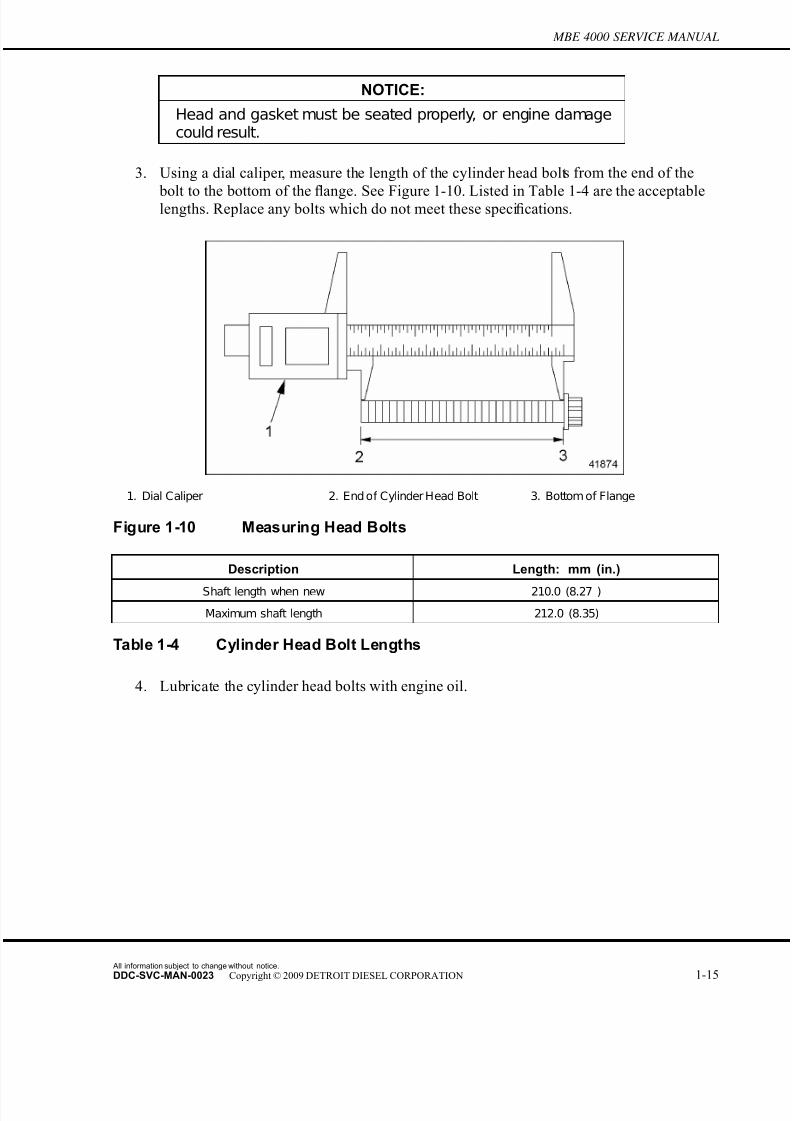
7/22/2019 Manual Mbe 4000 Taller
http://slidepdf.com/reader/full/manual-mbe-4000-taller 59/630
MBE 4000 SERVICE MANUAL
NOTICE:
Head and gasket must be seated properly, or engine damagecould result.
3. Using a dial caliper, measure the length of the cylinder head bolts from the end of the
bolt to the bottom of thefl
ange. See Figure 1-10. Listed in Table 1-4 are the acceptablelengths. Replace any bolts which do not meet these specifications.
1. Dial Caliper 2. End of Cylinder Head Bolt 3. Bottom of Flange
Figure 1-10 Measuring Head Bolts
Description Length: mm (in.)
Shaft length when new 210.0 (8.27 )
Maximum shaft length 212.0 (8.35)
Table 1-4 Cylinder Head Bolt Lengths
4. Lubricate the cylinder head bolts with engine oil.
All information subject to change without notice.
DDC-SVC-MAN-0023 Copyright © 2009 DETROIT DIESEL CORPORATION 1-15
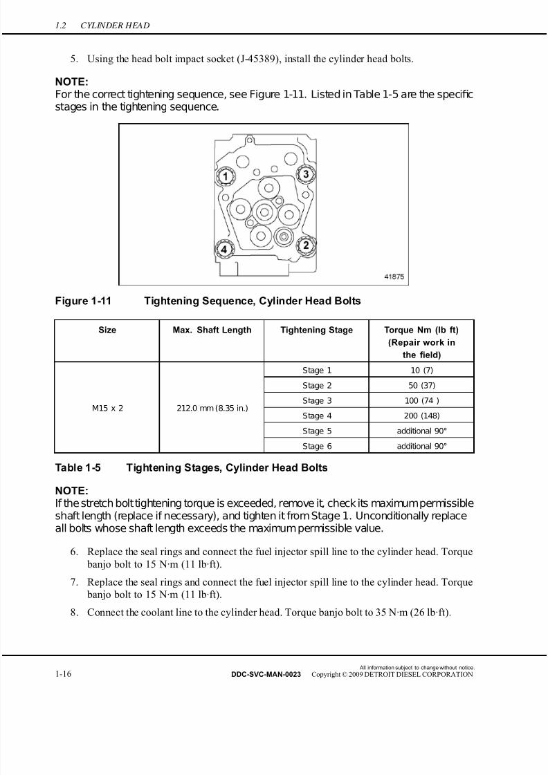
7/22/2019 Manual Mbe 4000 Taller
http://slidepdf.com/reader/full/manual-mbe-4000-taller 60/630
1.2 CYLINDER HEAD
5. Using the head bolt impact socket (J-45389), install the cylinder head bolts.
NOTE:For the correct tightening sequence, see Figure 1-11. Listed in Table 1-5 are the specificstages in the tightening sequence.
Figure 1-11 Tightening Sequence, Cylinder Head Bolts
Size Max. Shaft Length Tightening Stage Torque Nm (lb ft)
(Repair work in
the field)
Stage 1 10 (7)
Stage 2 50 (37)
Stage 3 100 (74 )
Stage 4 200 (148)
Stage 5 additional 90°
M15 x 2 212.0 mm (8.35 in.)
Stage 6 additional 90°
Table 1-5 Tightening Stages, Cylinder Head Bolts
NOTE:If the stretch bolttightening torque is exceeded, remove it, check its maximumpermissibleshaft length (replace if necessary), and tighten it from Stage 1. Unconditionally replaceall bolts whose shaft length exceeds the maximum permissible value.
6. Replace the seal rings and connect the fuel injector spill line to the cylinder head. Torque
banjo bolt to 15 N·m (11 lb·ft).
7. Replace the seal rings and connect the fuel injector spill line to the cylinder head. Torque
banjo bolt to 15 N·m (11 lb·ft).
8. Connect the coolant line to the cylinder head. Torque banjo bolt to 35 N·m (26 lb·ft).
All information subject to change without notice.
1-16 DDC-SVC-MAN-0023 Copyright © 2009 DETROIT DIESEL CORPORATION
7/22/2019 Manual Mbe 4000 Taller
http://slidepdf.com/reader/full/manual-mbe-4000-taller 61/630
MBE 4000 SERVICE MANUAL
NOTICE:
Correct torque on the high-pressure fuel lines are critical.Incorrect torques could result in leaks or lack of power due torestricted fuel flow.
9. Install the high-pressure fuel line and transfer tube. Refer to section 2.3.2.10. Install new exhaust manifold gaskets on all exhaust ports. Make sure the gaskets are
all positioned correctly.
NOTE:Install new manifold gaskets on all exhaust ports, regardless of how many heads wereremoved.
11. Install the exhaust manifold and tighten the bolts 50 N·m (37 lb·ft).
12. Install the charge-air intake manifold.
13. Lubricate the pushrods with a light coating of engine oil and install the pushrods, inorder, as removed.
14. Install the valve bridges, in order, as removed.
15. Install the rocker arm assembly, in or der, as removed. Tighten each rocker arm mounting
bolt first 60 N·m (44 lb·ft); then an additional 90°. Refer to section 1.22.4.
16. Install the barring tool and adjust the valves. For valve lash adjustment procedures,
refer to section 1.20.3.
NOTE:Make sure the pushrods are correctly seated in the valve tappets.
17. Remove the barring tool. Refer to section 1.16.1.
18. Install the inspection hole end cover on the flywheel housing. Tighten the fasteners 25
N·m (18 lb·ft).
19. Check that the coolant drain plug is tight and not leaking.
20. Fill the radiator with coolant.
21. Install the cylinder head cover.
22. Install the engine trim cover.
NOTE:Prime the fuel system.
All information subject to change without notice.
DDC-SVC-MAN-0023 Copyright © 2009 DETROIT DIESEL CORPORATION 1-17
7/22/2019 Manual Mbe 4000 Taller
http://slidepdf.com/reader/full/manual-mbe-4000-taller 62/630
1.2 CYLINDER HEAD
ENGINE EXHAUST
To avoid injury from inhaling engine exhaust, alwaysoperate the engine in a well-ventilated area. Engine
exhaust is toxic.
23. Turn on the ignition switch and test the engine. Observe the oil pressure gauge to verify the
correct oil pressure. The maximum oil pressure readings at idle speed are listed in Table
1-6. Pay attention to the coolant temperature gauge, warning lights, fluid leaks, and any
other signs of a problem.
Description Minimum Oil Pressure Reading: kPa (psi)
Engine at Idle Speed 50 (7)
Engine at Max. rpm 250 (36)
Table 1-6 Oil Pressure Readings
24. Stop the engine, check the coolant level, and top off if necessary.
1.2.2.1 Engine Compression Testing
Perform the following steps to compression test the engine:
Removal
1. Set the parking brake and chock the tires.
PERSONAL INJURY
To avoid injury before starting and running the engine,ensure the vehicle is parked on a level surface, parkingbrake is set, and the wheels are blocked.
2. Remove the cylinder head cover. Refer to section 1.1.1.
3. Adjust the valve lash. Refer to section 1.20.3.
NOTE: To do this procedure, coolant temperature must be between 70 - 95°C (155 - 205°F).
All information subject to change without notice.
1-18 DDC-SVC-MAN-0023 Copyright © 2009 DETROIT DIESEL CORPORATION
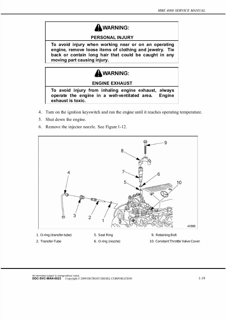
7/22/2019 Manual Mbe 4000 Taller
http://slidepdf.com/reader/full/manual-mbe-4000-taller 63/630
MBE 4000 SERVICE MANUAL
PERSONAL INJURY
To avoid injury when working near or on an operatingengine, remove loose items of clothing and jewelry. Tie
back or contain long hair that could be caught in anymoving part causing injury.
ENGINE EXHAUST
To avoid injury from inhaling engine exhaust, alwaysoperate the engine in a well-ventilated area. Engineexhaust is toxic.
4. Turn on the ignition keyswitch and run the engine until it reaches operating temperature.
5. Shut down the engine.
6. Remove the injector nozzle. See Figure 1-12.
1. O-ring (transfer-tube) 5. Seal Ring 9. Retaining Bolt
2. Transfer-Tube 6. O-ring (nozzle) 10. ConstantThrottle Valve Cover
All information subject to change without notice.
DDC-SVC-MAN-0023 Copyright © 2009 DETROIT DIESEL CORPORATION 1-19
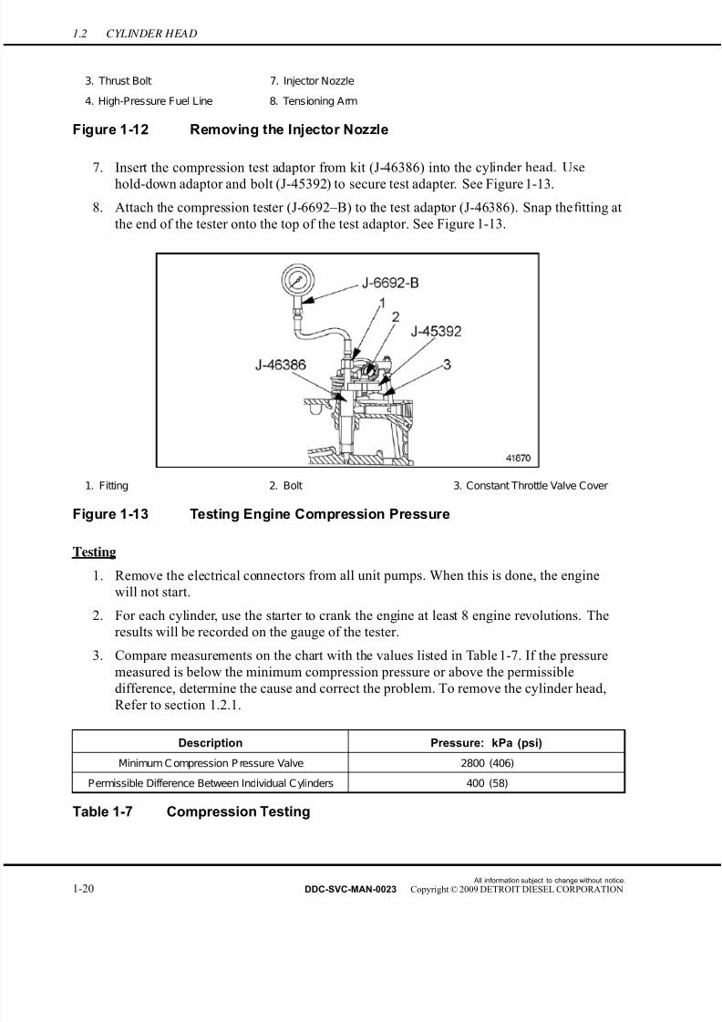
7/22/2019 Manual Mbe 4000 Taller
http://slidepdf.com/reader/full/manual-mbe-4000-taller 64/630
1.2 CYLINDER HEAD
3. Thrust Bolt 7. Injector Nozzle
4. High-Pressure Fuel Line 8. Tensioning Arm
Figure 1-12 Removing the Injector Nozzle
7. Insert the compression test adaptor from kit (J-46386) into the cylinder head. Use
hold-down adaptor and bolt (J-45392) to secure test adapter. See Figure 1-13.
8. Attach the compression tester (J-6692–B) to the test adaptor (J-46386). Snap the fitting at
the end of the tester onto the top of the test adaptor. See Figure 1-13.
1. Fitting 2. Bolt 3. Constant Throttle Valve Cover
Figure 1-13 Testing Engine Compression Pressure
Testing
1. Remove the electrical connectors from all unit pumps. When this is done, the engine
will not start.
2. For each cylinder, use the starter to crank the engine at least 8 engine revolutions. The
results will be recorded on the gauge of the tester.
3. Compare measurements on the chart with the values listed in Table 1-7. If the pressure
measured is below the minimum compression pressure or above the permissible
difference, determine the cause and correct the problem. To remove the cylinder head,
Refer to section 1.2.1.
Description Pressure: kPa (psi)
Minimum C ompression P ressure Valve 2800 (406)
Permissible Difference Between Individual Cylinders 400 (58)
Table 1-7 Compression Testing
All information subject to change without notice.
1-20 DDC-SVC-MAN-0023 Copyright © 2009 DETROIT DIESEL CORPORATION
7/22/2019 Manual Mbe 4000 Taller
http://slidepdf.com/reader/full/manual-mbe-4000-taller 65/630
MBE 4000 SERVICE MANUAL
Installation
1. Connect all electrical connections to the unit pumps, as removed.
2. Connect minidiag2 to the vehicle and clear all inactive faults.
NOTE:
Follow the equipment manufacturer's operating instructions.3. Disconnect the compression tester gauge, (J-6692–B) from the test adaptor (J-46386)
and hold down adapter (J-45392).
4. Remove the compression test adaptor.
5. Install the injector nozzle.
6. Install the cylinder head cover. Refer to section 1.1.2.
7. Repeat this procedure for each cylinder.
8. Remove the chocks from the tires.
All information subject to change without notice.
DDC-SVC-MAN-0023 Copyright © 2009 DETROIT DIESEL CORPORATION 1-21
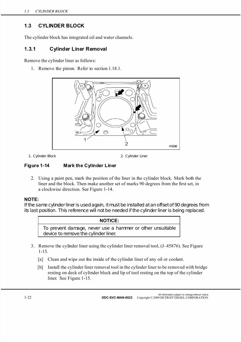
7/22/2019 Manual Mbe 4000 Taller
http://slidepdf.com/reader/full/manual-mbe-4000-taller 66/630
1.3 CYLINDER BLOCK
1.3 CYLINDER BLOCK
The cylinder block has integrated oil and water channels.
1.3.1 Cylinder Liner Removal
Remove the cylinder liner as follows:
1. Remove the piston. Refer to section 1.18.1.
1. Cylinder Block 2. Cylinder Liner
Figure 1-14 Mark the Cylinder Liner
2. Using a paint pen, mark the position of the liner in the cylinder block. Mark both theliner and the block. Then make another set of marks 90 degrees from the first set, in
a clockwise direction. See Figure 1-14.
NOTE:If the same cylinder liner is used again, itmust be installed atan offsetof 90 degrees fromits last position. This reference will not be needed if the cylinder liner is being replaced.
NOTICE:
To prevent damage, never use a hammer or other unsuitabledevice to remove the cylinder liner.
3. Remove the cylinder liner using the cylinder liner removal tool, (J–45876). See Figure
1-15.
[a] Clean and wipe out the inside of the cylinder liner of any oil or coolant.
[b] Install the cylinder liner removal tool in the cylinder liner to be removed with bridge
resting on deck of cylinder block and lip of tool resting on the top of the cylinder
liner. See Figure 1-15.
All information subject to change without notice.
1-22 DDC-SVC-MAN-0023 Copyright © 2009 DETROIT DIESEL CORPORATION
7/22/2019 Manual Mbe 4000 Taller
http://slidepdf.com/reader/full/manual-mbe-4000-taller 67/630
MBE 4000 SERVICE MANUAL
[c] Tighten the lower nut to expand the tool in the cylinder liner.See Figure 1-15.
[d] Tighten the upper nut on the tool until the cylinder liner is pulled from the cylinder
block. Remove the cylinder liner and tool. See Figure 1-15.
[e] Remove the tool from the liner.
1. Lower Nut 2. Resting Bridge 3. Upper Nut
Figure 1-15 Cylinder Liner Removal Tool J-45876
All information subject to change without notice.
DDC-SVC-MAN-0023 Copyright © 2009 DETROIT DIESEL CORPORATION 1-23

7/22/2019 Manual Mbe 4000 Taller
http://slidepdf.com/reader/full/manual-mbe-4000-taller 68/630
1.3 CYLINDER BLOCK
4. Remove the shim from the block counterbore.See Figure 1-16.
1. Collar S eat Insert (shim) 4. Liner S eat D-Ring
2. Cylinder Block A. Specified in Measuring Cylinder Liner Protrusion Table
3. Cylinder Liner
Figure 1-16 Cylinder Liner Collar Seat
5. Remove and discard the two O-rings from the block. See Figure 1-17.
1. Collar S eat Insert (shim) 5. Upper O-ring
2. Block 6. Lower O-ring
3. Cylinder Liner A. Specified in Measuring Cylinder Liner Protrusion
Table
4. Liner D-Ring
Figure 1-17 Cylinder Liner O-rings
All information subject to change without notice.
1-24 DDC-SVC-MAN-0023 Copyright © 2009 DETROIT DIESEL CORPORATION

7/22/2019 Manual Mbe 4000 Taller
http://slidepdf.com/reader/full/manual-mbe-4000-taller 69/630
MBE 4000 SERVICE MANUAL
6. Clean the cylinder block sealing areas and inspect for corrosion.
7. Check the condition of the cylinder liner collar seat. Ensure that the depth of the collar
seat is within the specifications listed in Table 1-8.
Description Dimensions: mm (in.)
Cylinder Liner Protrusion, From Block, see F igure1-16, Ref. A.
0.230–0.330 (0.0090–0.0130)
Height of the Cylinder Liner Collar, see Figure 1-16 10.10–10.12 (0.3976–0.3984)
Depth of the Collar Seat, see Figure 1-16 9.950–10.010 (0.3917–0.3941)
Thickness of the Seat Insert 0.14–0.16 (0.0055–0.0063)
Table 1-8 Cylinder Liner Installation Tolerances
8. Check the condition of the liner collar seat. Make sure that the depth of the collar seat is
within the specifications given, listed in Table 1-9.
Description Dimensions: mm (in.)
Admissible Out-of-Round of the Cylinder Liner,
where it contacts the O-ringsMax.: 0.02 (0.0008)
Admissible Deformation of the Cylinder Liner Collar,
at the Contact Surface with the Seat InsertMax.: 0.02 (0.0008)
Admissible Deformation of the Cylinder Liner Collar
Seat, at the Contact Surface with the Seat InsertMax.: 0.03 (0.0012)
Table 1-9 Cylinder Liner Inspection Tolerances
1.3.1.1 Cylinder Liner Bore Inspection and Measurement
Inspection
Inspect the cylinder liner bore as follows:
1. Check the wall of the cylinder liner for signs of excessive wear or deformation.
All information subject to change without notice.
DDC-SVC-MAN-0023 Copyright © 2009 DETROIT DIESEL CORPORATION 1-25

7/22/2019 Manual Mbe 4000 Taller
http://slidepdf.com/reader/full/manual-mbe-4000-taller 70/630
1.3 CYLINDER BLOCK
2. ·heck the honing pattern on the cylinder liner for damage caused by penetration of dirt into
the cylinder. If the honing pattern is faded or no longer visible, discard the cylinder liner.
See Figure 1-18 for an intact honing pattern and see Figure 1-19 for a faded honing pattern.
NOTE:Minor fading of the honing pattern at the top ring inversion area is not suf ficient cause
to reject the liner.
Figure 1-18 Intact Honing Pattern
Figure 1-19 Faded Honing Pattern
3. Do an external visual check of the cylinder liner for signs of cavitation and corrosion.
Discard the liner if any damage is noted.
Measurement
All information subject to change without notice.
1-26 DDC-SVC-MAN-0023 Copyright © 2009 DETROIT DIESEL CORPORATION
7/22/2019 Manual Mbe 4000 Taller
http://slidepdf.com/reader/full/manual-mbe-4000-taller 71/630
MBE 4000 SERVICE MANUAL
1. Set the dial gauge and quick calipers with a dial caliper to the inside diameter of the
cylinder liner. Preload the dial gauge to 5 mm (0.20 in.). See Figure 1-20 for set-up
and listed in Table 1-10 are specifications.
1. Dial Gauge 2. Quick Calipers (for internal
measurements)
3. Dial Caliper
Figure 1-20 Setting the Dial Gauge
Where To Measure What To Measure Value: mm (in.)
Measuring Point 1: At the area
of the O-rings
Inside Diameter of the Cylinder
Liner, A Class127.990–127.995 (5.0390–5.0392)
Measuring Point 1: At the area
of the O-rings
Inside Diameter of the Cylinder
Liner, B Class127.995–128.005 (5.0392–5.0396)
Measuring Point 1: At the area
of the O-rings
Inside Diameter of the Cylinder
Liner, C Class128.005–128.010 (5.0396–5.0398)
Measuring Point 2: Upper Reversal
Point of the First Piston Ring
Max. Wear to Cylinder Liner,
Measured Along Axis A and Axis B0.08 (0.003)
At Measuring P oint 2, Compare
Axis A to Axis BAdmissible Wear Out Max.: 0.08 (0.003)
Table 1-10 Cylinder Liner Measurements
NOTE: This measurement serves as a baseline against which to measure the actual wear.
All information subject to change without notice.
DDC-SVC-MAN-0023 Copyright © 2009 DETROIT DIESEL CORPORATION 1-27
7/22/2019 Manual Mbe 4000 Taller
http://slidepdf.com/reader/full/manual-mbe-4000-taller 72/630
1.3 CYLINDER BLOCK
2. Measure the inside diameter of the cylinder liner at measuring point 1: near the O-ring
area. See Figure 1-21.
Figure 1-21 Measuring the Inside Diameter
[a] Make the first measurement along the fore-to-aft axis.
[b] Make the second measurement 90 degrees away, along the side-to-side axis.
[c] When finished, set the dial gauge to zero.
3. Measure the wear on the inside diameter of the liner at measuring point 2: the upper
reversal point of the first piston ring. Measure the cylinder liner in both directions:
fore-to-aft and side-to-side. See Figure 1-22. The specifications are listed in Table 1-10.
1. Cylinder Liner 2. Measuring P oint 2 (upper reversal point of the first
piston ring)
Figure 1-22 Measuring Points
All information subject to change without notice.
1-28 DDC-SVC-MAN-0023 Copyright © 2009 DETROIT DIESEL CORPORATION
7/22/2019 Manual Mbe 4000 Taller
http://slidepdf.com/reader/full/manual-mbe-4000-taller 73/630
MBE 4000 SERVICE MANUAL
[a] Make the first measurement along the fore-to-aft axis (axis A).
[b] Make the second measurement 90 degrees away, along the side-to-side axis (axis B).
[c] If there is more than 0.08 mm (0.003 in.) of wear, replace the cylinder liner.
4. Check the cylinder liner for out-of-round. If the two measurements vary by more than
0.010 mm (0.0004 in.), replace the cylinder liner.
5. Replace the cylinder liner, if required. Refer to section 1.3.1.
1.3.1.2 Measurement of Cylinder Liner Protrusion
Measurement steps are as follows:
1. Clean the contact surfaces of the cylinder block, the cylinder liner, and the measuring plate.
NOTE:Correct cylinder liner protrusion is necessary to obtain a perfect seal when the headgasket is compressed by the cylinder head.
2. Install the liner and shim into the block without the seals.
3. Install the measuring plate (J–46180) on the cylinder block and cylinder liner. Fasten the
measuring plate to the block by inserting the cylinder head bolts into the spacers and then
threading them into the holes in the cylinder block. See Figure 1-23.
1. Cylinder Head Bolts
Figure 1-23 Measuring Plate Installation
4. Tighten the cylinder head bolts 50 N·m (37 lb·ft).
All information subject to change without notice.
DDC-SVC-MAN-0023 Copyright © 2009 DETROIT DIESEL CORPORATION 1-29
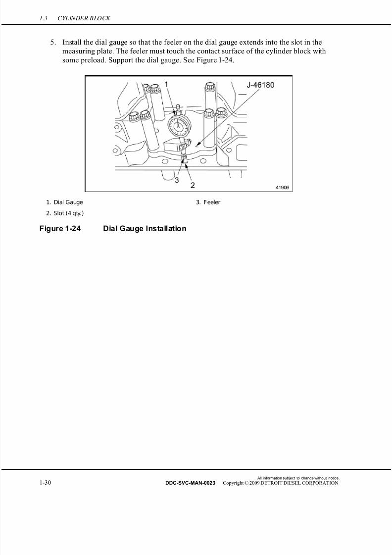
7/22/2019 Manual Mbe 4000 Taller
http://slidepdf.com/reader/full/manual-mbe-4000-taller 74/630
1.3 CYLINDER BLOCK
5. Install the dial gauge so that the feeler on the dial gauge extends into the slot in the
measuring plate. The feeler must touch the contact surface of the cylinder block with
some preload. Support the dial gauge. See Figure 1-24.
1. Dial Gauge 3. Feeler
2. Slot (4 qty.)
Figure 1-24 Dial Gauge Installation
All information subject to change without notice.
1-30 DDC-SVC-MAN-0023 Copyright © 2009 DETROIT DIESEL CORPORATION

7/22/2019 Manual Mbe 4000 Taller
http://slidepdf.com/reader/full/manual-mbe-4000-taller 75/630
MBE 4000 SERVICE MANUAL
6. Measure the cylinder liner protrusion from the block in four places, once at each slot in the
measuring plate. See Figure 1-25. The acceptance/rejection criteria is listed in Table 1-11.
1. Collar S eat Insert (shim) 4. Liner S eat D-Ring
2. Cylinder Block A. Specified in Measuring Cylinder Liner Protrusion
Table
3. Cylinder Liner
Figure 1-25 Measuring Protrusion
Description Value: mm (in.)
Cylinder Liner Protrusion From Block 0.230–0.330 (0.0090–0.0130)
Difference Between the Four Measuring Points Max.: 0.02 (0.0007)
Table 1-11 Specifications for Measuring Cylinder Liner Protrusion
[a] Set the scale on the dial gauge to zero.
[b] Move the dial gauge until the feeler touches the cylinder liner collar. Record the
reading on the dial gauge.
[c] Move the dial gauge and support to the next slot, and repeat the measurement process,
until four measurements have been made, one at each slot. Record each measurement.
[d] Check each measurement. If any one measurement records protrusion of less than
0.230 mm (0.0090 in.), or more than 0.330 mm (0.0130 in.), remove the cylinder
liner and check it according to the procedures that refer to section 1.3.3.
NOTE: There are three different cylinder liner shim thicknesses that are available, 0.15mm,0.30mm and 0.50mm.
[e] Compare the four measurements. If any measurement differs from any one of the
others by more than 0.02 mm (0.0008 in.), replace the cylinder liner and repeat
All information subject to change without notice.
DDC-SVC-MAN-0023 Copyright © 2009 DETROIT DIESEL CORPORATION 1-31

7/22/2019 Manual Mbe 4000 Taller
http://slidepdf.com/reader/full/manual-mbe-4000-taller 76/630
1.3 CYLINDER BLOCK
steps “a” through “e”. If the cylinder liner measurements are within specification
continue to step 7.
7. Remove the bolts, spacers and measuring plate as installed.
1.3.1.3 Fuel System Leak Test
Perform the following procedure to ensure that the fuel gallery is properly sealed and does not
leak.
NOTE: This procedure can be performed with the engine installed or removed fromthe vehicle.
FIRE
To avoid injury from fire, keep all potential ignition sources
away from diesel fuel, including open flames, sparks, andelectrical resistance heating elements. Do not smoke whenrefueling.
1. Drain all fuel from engine.
2. Remove all six electronic unit pumps from the engine block.
All information subject to change without notice.
1-32 DDC-SVC-MAN-0023 Copyright © 2009 DETROIT DIESEL CORPORATION
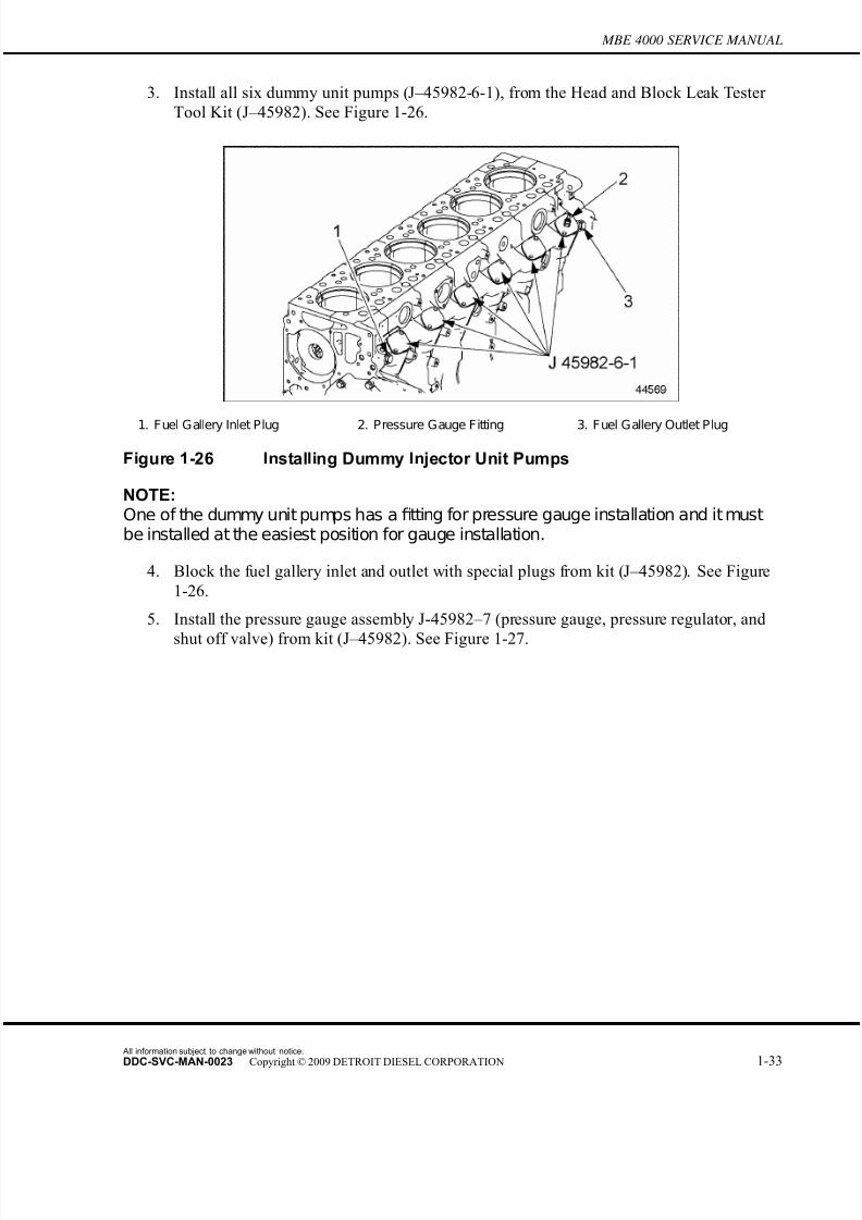
7/22/2019 Manual Mbe 4000 Taller
http://slidepdf.com/reader/full/manual-mbe-4000-taller 77/630
MBE 4000 SERVICE MANUAL
3. Install all six dummy unit pumps (J–45982-6-1), from the Head and Block Leak Tester
Tool Kit (J–45982). See Figure 1-26.
1. Fuel Gallery Inlet Plug 2. Pressure Gauge Fitting 3. Fuel Gallery Outlet Plug
Figure 1-26 Installing Dummy Injector Unit Pumps
NOTE:One of the dummy unit pumps has a fitting for pressure gauge installation and it mustbe installed at the easiest position for gauge installation.
4. Block the fuel gallery inlet and outlet with special plugs from kit (J–45982). See Figure
1-26.
5. Install the pressure gauge assembly J-45982–7 (pressure gauge, pressure regulator, and
shut off valve) from kit (J–45982). See Figure 1-27.
All information subject to change without notice.
DDC-SVC-MAN-0023 Copyright © 2009 DETROIT DIESEL CORPORATION 1-33

7/22/2019 Manual Mbe 4000 Taller
http://slidepdf.com/reader/full/manual-mbe-4000-taller 78/630
1.3 CYLINDER BLOCK
6. Connect a compressed air supply to the pressure gauge assembly.
1. Pressure Gauge J -45982–7 on Dummy Unit Pump
Figure 1-27 Installing Pressure Gauge Assembly to Dummy Unit Pump
EYE INJURY
To avoid injury from flying debris when using compressedair, wear adequate eye protection (face shield or safetygoggles) and do not exceed 276 kPa (40 psi) air pressure.
7. Pressurize the system with 200 kPa (29 psi). Use the pressure regulator to set the pressure.
8. Check for leaks around the dummy unit pumps and inlet/outlet plugs using a soap
solution. Repair any leaks.
9. Close the shut off valve.
10. Watch the pressure for 30 seconds. If the pressure holds at 200 kPa (29 psi), the fuel gallery
is properly sealing. In case of a pressure drop, the engine block should not be reused.
All information subject to change without notice.
1-34 DDC-SVC-MAN-0023 Copyright © 2009 DETROIT DIESEL CORPORATION

7/22/2019 Manual Mbe 4000 Taller
http://slidepdf.com/reader/full/manual-mbe-4000-taller 79/630
MBE 4000 SERVICE MANUAL
EYE INJURY
To avoid injury from flying debris when using compressedair, wear adequate eye protection (face shield or safety
goggles) and do not exceed 276 kPa (40 psi) air pressure.
1.3.1.4 Cylinder Block Leak Test
Perform the following steps to conduct a cylinder block leak test to see if the engine block is
leaking coolant.
NOTE: This procedure can only be performed with the engine removed from the vehicle andusing only the engine block with the liners installed.
1. Place the engine block with installed liners on the engine stand.
2. Install all six top block cover plates (J–45982-1) from the Head and Block Leak Test kit
(J–45982) using the special bolts supplied. See Figure 1-28.
1. Block Cover Plates (6) - part of kit J –45982 3. Pressure Gauge Fitting
2. Water Pump Cover Plate - part of kitJ –45982 4. Oil Cooler/Filter Housing Cover Plate - part of kit
J –45982
Figure 1-28 Installing Block Cover Plates
3. Install the oil cooler/filter housing cover plate, from the kit, on the right hand side of the
engine block using supplied hardware. See Figure 1-28.
All information subject to change without notice.
DDC-SVC-MAN-0023 Copyright © 2009 DETROIT DIESEL CORPORATION 1-35

7/22/2019 Manual Mbe 4000 Taller
http://slidepdf.com/reader/full/manual-mbe-4000-taller 80/630
1.3 CYLINDER BLOCK
4. Install the water pump cover plate, from the kit, on the front of the engine using supplied
hardware. See Figure 1-28.
NOTE: The water pump cover plate has a fitting for installing the supplied pressure gauge.
5. Block the air compressor coolant inlet and outlet from the engine block with the special plugs and copper washers as supplied in the leak test kit (J–45982). See Figure 1-29.
1. Coolant Line to Air Compressor 2. Air Compressor Outlet location from Engine Block
Figure 1-29 Blocking Air Compressor Inlet/Outlet from Engine Block
6. Install the pressure gauge assembly J-45982–7 (pressure gauge, pressure regulator, and
shut off valve) from kit (J–45982). See Figure 1-30.
1. Pressure Gauge Assembly J -45987–2
Figure 1-30 Installing Pressure Gauge Assembly
All information subject to change without notice.
1-36 DDC-SVC-MAN-0023 Copyright © 2009 DETROIT DIESEL CORPORATION
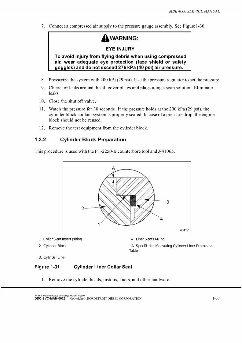
7/22/2019 Manual Mbe 4000 Taller
http://slidepdf.com/reader/full/manual-mbe-4000-taller 81/630
MBE 4000 SERVICE MANUAL
7. Connect a compressed air supply to the pressure gauge assembly. See Figure 1-30.
EYE INJURY
To avoid injury from flying debris when using compressedair, wear adequate eye protection (face shield or safetygoggles) and do not exceed 276 kPa (40 psi) air pressure.
8. Pressurize the system with 200 kPa (29 psi). Use the pressure regulator to set the pressure.
9. Check for leaks around the all cover plates and plugs using a soap solution. Eliminate
leaks.
10. Close the shut off valve.
11. Watch the pressure for 30 seconds. If the pressur e holds at the 200 kPa (29 psi), the
cylinder block coolant system is properly sealed. In case of a pressure drop, the engine
block should not be reused.
12. Remove the test equipment from the cylinder block.
1.3.2 Cylinder Block Preparation
This procedure is used with the PT-2250-B counterbore tool and J-41065.
1. Collar S eat Insert (shim) 4. Liner S eat D-Ring2. Cylinder Block A. Specified in Measuring Cylinder Liner Protrusion
Table
3. Cylinder Liner
Figure 1-31 Cylinder Liner Collar Seat
1. Remove the cylinder heads, pistons, liners, and other hardware.
All information subject to change without notice.
DDC-SVC-MAN-0023 Copyright © 2009 DETROIT DIESEL CORPORATION 1-37
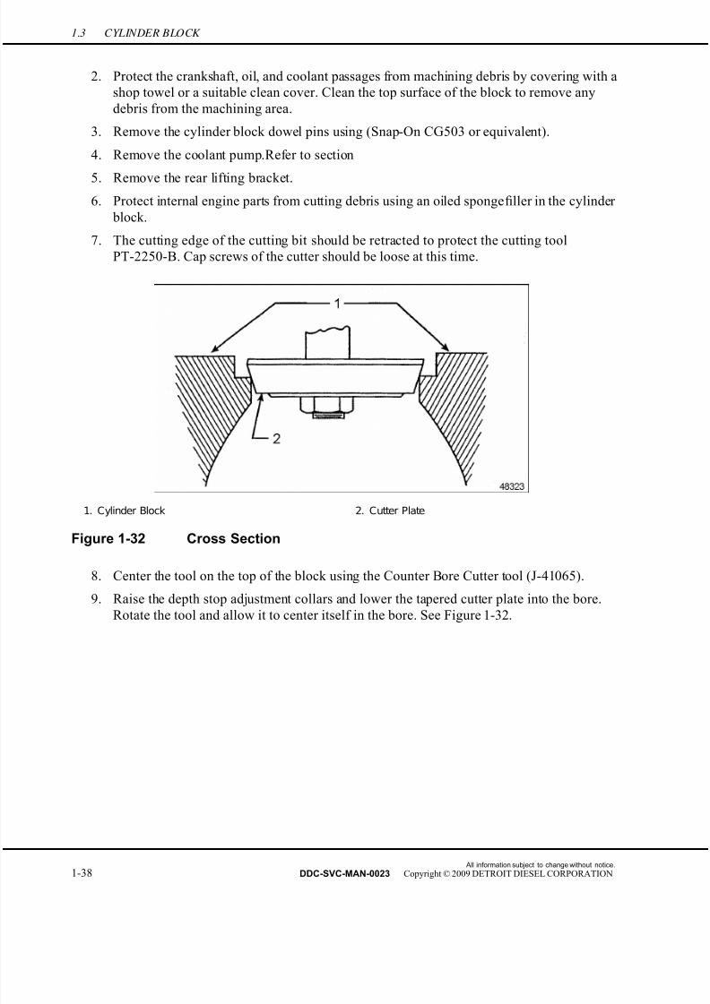
7/22/2019 Manual Mbe 4000 Taller
http://slidepdf.com/reader/full/manual-mbe-4000-taller 82/630
1.3 CYLINDER BLOCK
2. Protect the crankshaft, oil, and coolant passages from machining debris by covering with a
shop towel or a suitable clean cover. Clean the top surface of the block to remove any
debris from the machining area.
3. Remove the cylinder block dowel pins using (Snap-On CG503 or equivalent).
4. Remove the coolant pump.Refer to section
5. Remove the rear lifting bracket.
6. Protect internal engine parts from cutting debris using an oiled sponge filler in the cylinder
block.
7. The cutting edge of the cutting bit should be retracted to protect the cutting tool
PT-2250-B. Cap screws of the cutter should be loose at this time.
1. Cylinder Block 2. Cutter Plate
Figure 1-32 Cross Section
8. Center the tool on the top of the block using the Counter Bore Cutter tool (J-41065).
9. Raise the depth stop adjustment collars and lower the tapered cutter plate into the bore.
Rotate the tool and allow it to center itself in the bore. See Figure 1-32.
All information subject to change without notice.
1-38 DDC-SVC-MAN-0023 Copyright © 2009 DETROIT DIESEL CORPORATION

7/22/2019 Manual Mbe 4000 Taller
http://slidepdf.com/reader/full/manual-mbe-4000-taller 83/630
MBE 4000 SERVICE MANUAL
10. Install two opposing cylinder head bolts with the washers and spacers through the base
plate of the tool. See Figure 1-33. Tighten securely to 41 N·m (30 lbs. ft.).
1. Cylinder Head Bolt 2. Cylinder Block
Figure 1-33 Cutting Tool
11. Raise the tapered cutter head from the block and install the depth set spacer provided.
While there is no load, extend the cutting tool outward (using a clockwise rotation of the
cutting screw) until it just touches a 0.15mm feeler gauge or shim placed next to the
vertical wall of the counterbore. Tighten the Allen head hold-down screws. See Figure
1-33.
NOTICE:
Do notturn pastthis position orthecutterplate willfitandpreventan accurate reading.
12. Lower the cutting plate and cutter tool into the counterbore until it just touches the lower
surface of the counterbore. Rotate the lock collars downward until they touch the bronze
bushing of the tool.
13. Set the depth of cut by adjusting the top collar upwards to allow the liner shim to be
inserted between the two collars. Tighten the thumb screw of the top collar. Removethe shim.
14. Lubricate the tool bushing. Back off the lower collar by two graduations 0.0254 mm
(0.001 in. each). Rotate the T-handle clockwise with a moderate, constant pressure. Stop
at random positions to prevent creating a ridge in the counterbore. Continue backing
off the adjustment in 0.0508 mm (0.002 in.) increments for the balance of the cutting
operation until the collars come together.
All information subject to change without notice.
DDC-SVC-MAN-0023 Copyright © 2009 DETROIT DIESEL CORPORATION 1-39
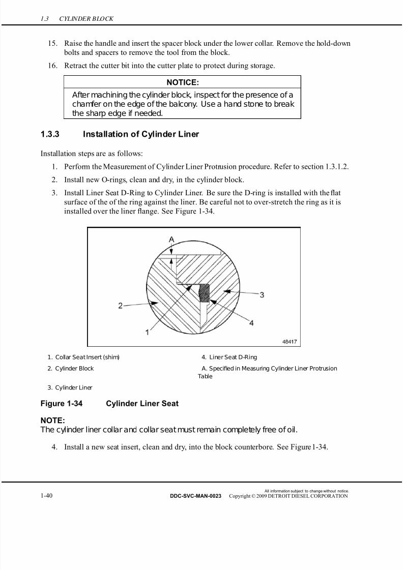
7/22/2019 Manual Mbe 4000 Taller
http://slidepdf.com/reader/full/manual-mbe-4000-taller 84/630
1.3 CYLINDER BLOCK
15. Raise the handle and insert the spacer block under the lower collar. Remove the hold-down
bolts and spacers to remove the tool from the block.
16. Retract the cutter bit into the cutter plate to protect during storage.
NOTICE:
After machining the cylinder block, inspect for the presence of achamfer on the edge of the balcony. Use a hand stone to breakthe sharp edge if needed.
1.3.3 Installation of Cylinder Liner
Installation steps are as follows:
1. Perform the Measurement of Cylinder Liner Protr usion procedure. Refer to section 1.3.1.2.
2. Install new O-rings, clean and dry, in the cylinder block.
3. Install Liner Seat D-Ring to Cylinder Liner. Be sure the D-ring is installed with the flat
surface of the of the ring against the liner. Be careful not to over-stretch the ring as it isinstalled over the liner flange. See Figure 1-34.
1. Collar Seat Insert (shim) 4. Liner Seat D-Ring
2. Cylinder Block A. Specified in Measuring Cylinder Liner Protrusion
Table
3. Cylinder Liner
Figure 1-34 Cylinder Liner Seat
NOTE: The cylinder liner collar and collar seat must remain completely free of oil.
4. Install a new seat insert, clean and dry, into the block counterbore. See Figure 1-34.
All information subject to change without notice.
1-40 DDC-SVC-MAN-0023 Copyright © 2009 DETROIT DIESEL CORPORATION

7/22/2019 Manual Mbe 4000 Taller
http://slidepdf.com/reader/full/manual-mbe-4000-taller 85/630
MBE 4000 SERVICE MANUAL
5. Apply a light coating of engine oil to the lower part of the cylinder liner, from where it
contacts the O-rings up to the bevelled area.
6. When installing a new cylinder liner, make sure that the diameter tolerance code
corresponds to the one marked on the piston.See Figure 1-35 for the location of tolerance
codes.
1. Piston 2. Cylinder Liner
Figure 1-35 Tolerance Codes
[a] Cylinder liners with tolerance code A require a piston of code BA.
[b] Cylinder liners with tolerance code B require a piston of either code BA or BC.
[c] Cylinder liners with tolerance code C require a piston of code BC.
All information subject to change without notice.
DDC-SVC-MAN-0023 Copyright © 2009 DETROIT DIESEL CORPORATION 1-41

7/22/2019 Manual Mbe 4000 Taller
http://slidepdf.com/reader/full/manual-mbe-4000-taller 86/630
1.3 CYLINDER BLOCK
7. Install the cylinder liner, using the cylinder liner installation tool (J–46168). See Figure
1-36.
1. Installation Nut 3. Cylinder Block2. Cylinder Liner
Figure 1-36 Cylinder Liner
NOTICE:
Do not overtighten the installation tool. This may deform thecylinder liner and make the installation tool more dif ficult toremove.
[a] Tighten the installation tool just enough to hold the installation tool inside the
cylinder liner without turning.
NOTICE:
To prevent damage to the O-rings, the cylinder liner must berotated during installation.
NOTE:If installing the old cylinder liner, offset the reference marks 90 degrees fromthe previousones.
[b] Insert the cylinder liner into the cylinder block until it contacts the O-rings. Continueto insert the cylinder liner past the O-rings, being careful to keep turning the
installation tool until the cylinder liner is properly seated.
[c] Remove the installation tool from the cylinder liner.
All information subject to change without notice.
1-42 DDC-SVC-MAN-0023 Copyright © 2009 DETROIT DIESEL CORPORATION

7/22/2019 Manual Mbe 4000 Taller
http://slidepdf.com/reader/full/manual-mbe-4000-taller 87/630
MBE 4000 SERVICE MANUAL
8. Measure the cylinder liner protrusion from the block. The specifications are listed in Table
1-12.
Description Dimensions: mm (in.)
Cylinder Liner Protrusion, From Block, see F igure
1-16, Ref. A.
0.230–0.330 (0.0090–0.0130)
Height of the Cylinder Liner Collar, see Figure 1-16 10.10–10.12 (0.3976–0.3984)
Depth of the Collar Seat, see Figure 1-16 9.950–10.010 (0.3917–0.3941)
Thickness of the Seat Insert 0.14–0.16 (0.0055–0.0063)
Table 1-12 Cylinder Liner Installation Tolerances
9. Measure the inside diameter of the cylinder liner and check for out-of-round. See Figure
1-37.
1. Cylinder Liner 3. Dial Gauge
2. Quick Calipers 4. Cylinder Block
Figure 1-37 Measuring the Cylinder Liner Inside Diameter
[a] Measure at three different locations 60 degrees apart in the area of the two O-rings.
[b] Compare the three measurements. If they differ by more than the maximum
admissible out-of-round listed in Table 1-12, remove the cylinder liner and inspect
the two O-rings and their seating area in the cylinder block.[c] If the O-rings are damaged, replace them.
[d] Check the out-of-round again until it meets specifications.
10. Install the piston. Refer to section 1.18.1.
All information subject to change without notice.
DDC-SVC-MAN-0023 Copyright © 2009 DETROIT DIESEL CORPORATION 1-43

7/22/2019 Manual Mbe 4000 Taller
http://slidepdf.com/reader/full/manual-mbe-4000-taller 88/630
1.4 EGR CYLINDER HEAD AND BLOCK
1.4 EGR CYLINDER HEAD AND BLOCK
There are several minor changes in the cylinder liner, block and engine lifter brack ets between the
MBE 4000 EGR engine and the non-EGR engine.
1.4.1 EGR Cylinder Head Installation
Be aware of the following notice when installing the cylinder head on an EGR engine:
NOTICE:
Be sure the carbon scraper ring is seated in the groove on thetop partof the cylinder liner before installing a new cylinder headgasketand the cylinder head, otherwise componentdamagecanresult. See Figure 1-38.
1. Cylinder Liner 3. Installed Piston
2. Carbon Scraper Ring 4. Carbon Scraper Ring located in groove in cylinder
liner
Figure 1-38 Installed Carbon Scraper Ring
NOTE:All remaining installation procedures for the cylinder head are identical to anon-EGR engine.
All information subject to change without notice.
1-44 DDC-SVC-MAN-0023 Copyright © 2009 DETROIT DIESEL CORPORATION
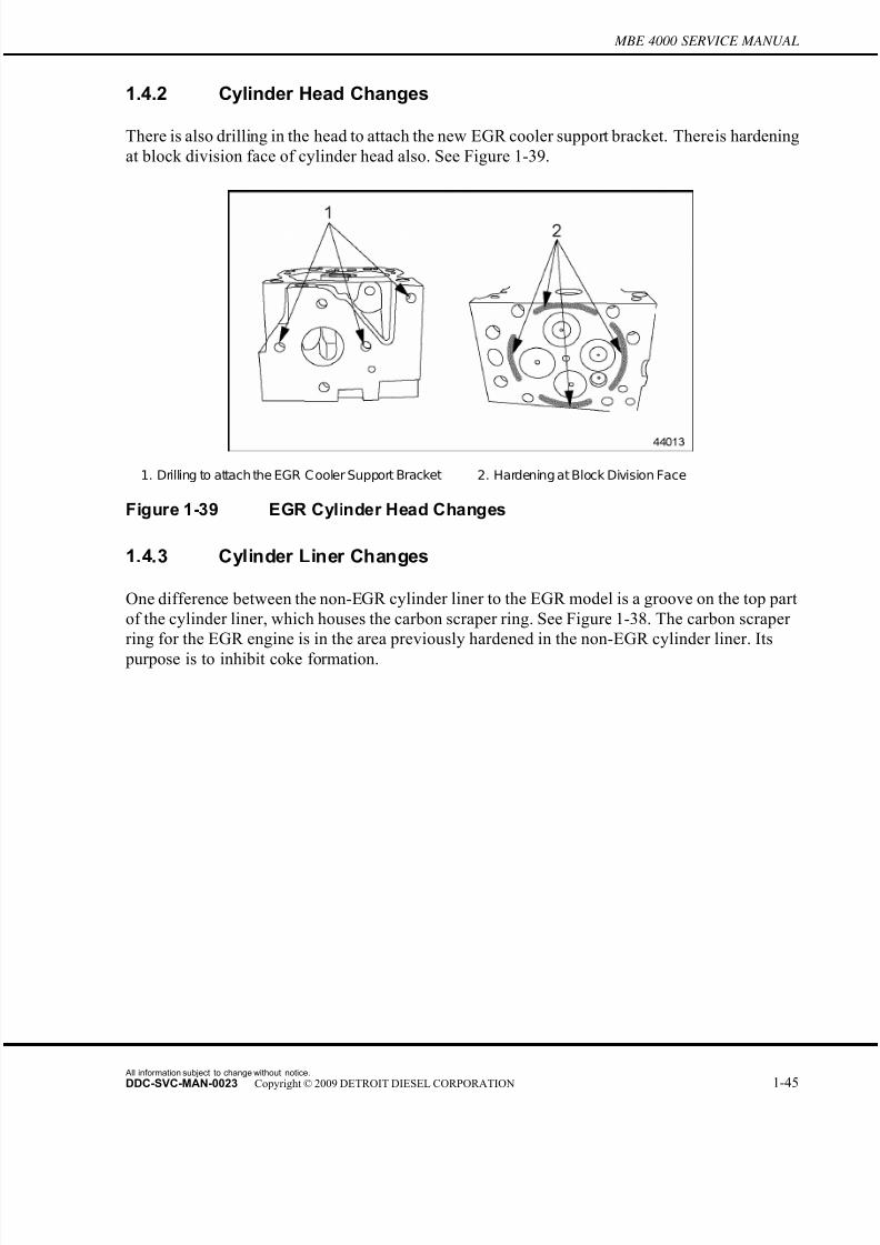
7/22/2019 Manual Mbe 4000 Taller
http://slidepdf.com/reader/full/manual-mbe-4000-taller 89/630
MBE 4000 SERVICE MANUAL
1.4.2 Cylinder Head Changes
There is also drilling in the head to attach the new EGR cooler support bracket. There is hardening
at block division face of cylinder head also. See Figure 1-39.
1. Drilling to attach the EGR C ooler Support Bracket 2. Hardening at Block Division Face
Figure 1-39 EGR Cylinder Head Changes
1.4.3 Cylinder Liner Changes
One difference between the non-EGR cylinder liner to the EGR model is a groove on the top part
of the cylinder liner, which houses the carbon scraper ring. See Figure 1-38. The carbon scraper
ring for the EGR engine is in the area previously hardened in the non-EGR cylinder liner. Its
purpose is to inhibit coke formation.
All information subject to change without notice.
DDC-SVC-MAN-0023 Copyright © 2009 DETROIT DIESEL CORPORATION 1-45
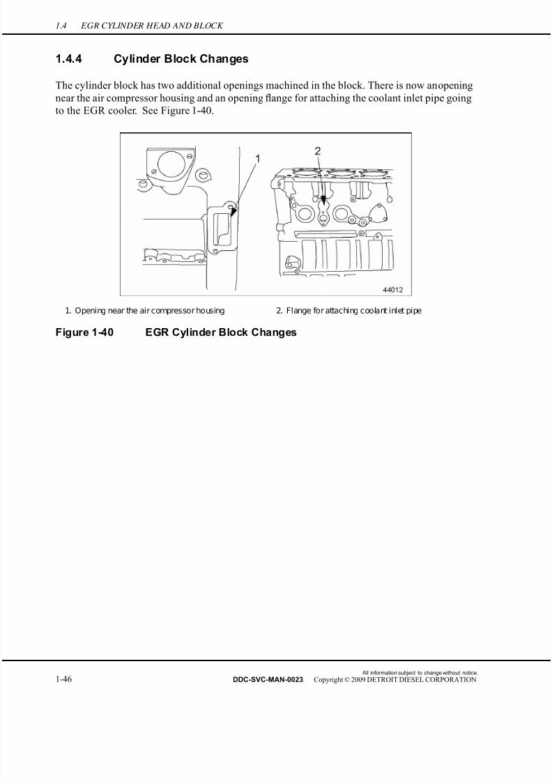
7/22/2019 Manual Mbe 4000 Taller
http://slidepdf.com/reader/full/manual-mbe-4000-taller 90/630
1.4 EGR CYLINDER HEAD AND BLOCK
1.4.4 Cylinder Block Changes
The cylinder block has two additional openings machined in the block. There is now an opening
near the air compressor housing and an opening flange for attaching the coolant inlet pipe going
to the EGR cooler. See Figure 1-40.
1. Opening near the air compressor housing 2. Flange for attaching coolant inlet pipe
Figure 1-40 EGR Cylinder Block Changes
All information subject to change without notice.
1-46 DDC-SVC-MAN-0023 Copyright © 2009 DETROIT DIESEL CORPORATION

7/22/2019 Manual Mbe 4000 Taller
http://slidepdf.com/reader/full/manual-mbe-4000-taller 91/630
MBE 4000 SERVICE MANUAL
1.5 EGR FRONT AND REAR LIFTER BRACKETS
The front lifter bracket on the non-EGR engine was moulded into the coolant pump. The
EGR engine has separate front and rear lifter brackets.
NOTICE:
A spreader bar must be used at all times in conjunction with thefront and rear lifter brackets to liftthe EGR engine to ensure thatno engine damage will result. The brackets are designed to liftvertically.
1.5.1 Removal of Front and Rear Lifter Brackets
Perform the following steps to remove the front and rear lifter brackets:
1. Remove the four M10 x 25 mm mounting bolts from the front lifter bracket and remove
the bracket. See Figure 1-41.
1. Front Lifter Bracket Mounting Bolts 2. Front Lifter Bracket
Figure 1-41 Removal / Installation of Front Lifter Bracket
2. Remove the bolt from the air compressor coolant line bracket on the rear lifting bracket.
See Figure 1-42.
All information subject to change without notice.
DDC-SVC-MAN-0023 Copyright © 2009 DETROIT DIESEL CORPORATION 1-47
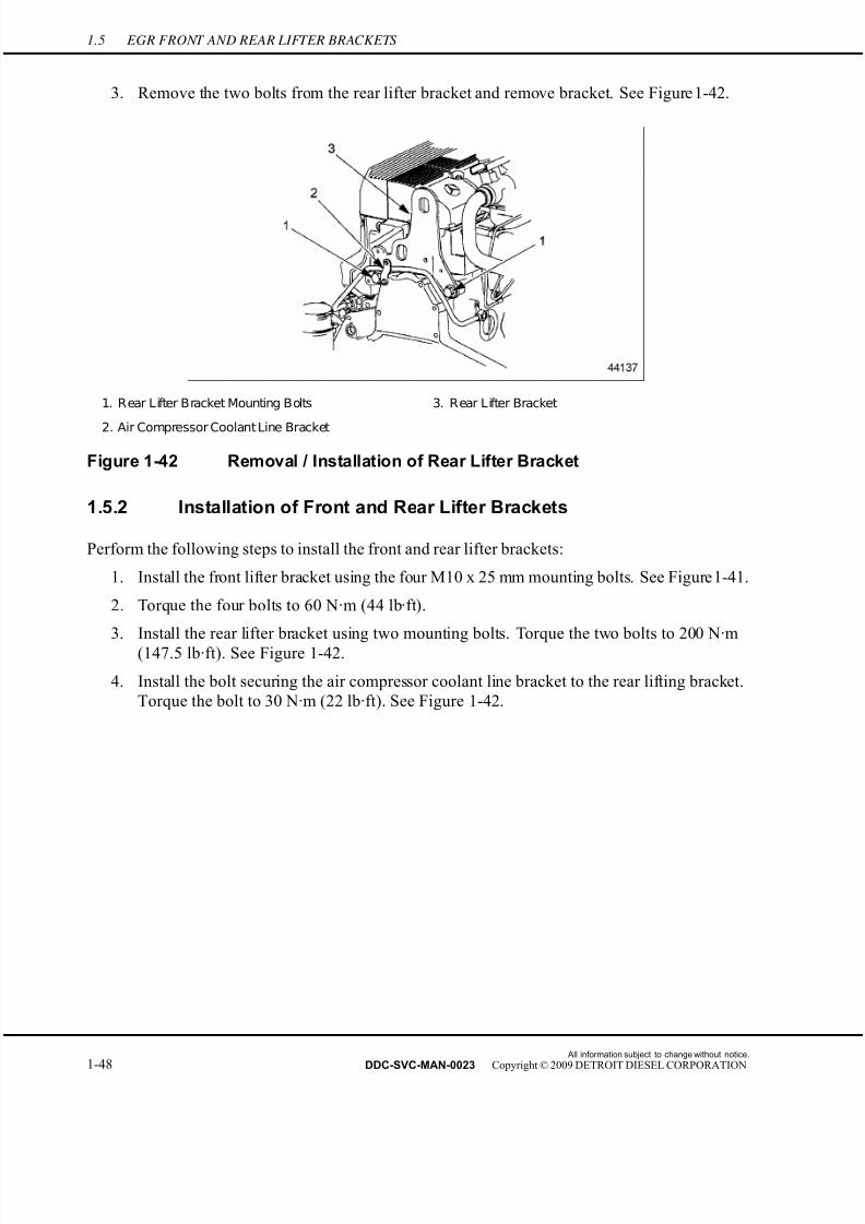
7/22/2019 Manual Mbe 4000 Taller
http://slidepdf.com/reader/full/manual-mbe-4000-taller 92/630
1.5 EGR FRONT AND REAR LIFTER BRACKETS
3. Remove the two bolts from the rear lifter bracket and remove bracket. See Figure 1-42.
1. Rear Lifter Bracket Mounting Bolts 3. Rear Lifter Bracket
2. Air Compressor Coolant Line Bracket
Figure 1-42 Removal / Installation of Rear Lifter Bracket
1.5.2 Installation of Front and Rear Lifter Brackets
Perform the following steps to install the front and rear lifter brackets:
1. Install the front lifter bracket using the four M10 x 25 mm mounting bolts. See Figure 1-41.
2. Torque the four bolts to 60 N·m (44 lb·ft).
3. Install the rear lifter bracket using two mounting bolts. Torque the two bolts to 200 N·m
(147.5 lb·ft). See Figure 1-42.
4. Install the bolt securing the air compressor coolant line bracket to the rear lifting bracket.
Torque the bolt to 30 N·m (22 lb·ft). See Figure 1-42.
All information subject to change without notice.
1-48 DDC-SVC-MAN-0023 Copyright © 2009 DETROIT DIESEL CORPORATION
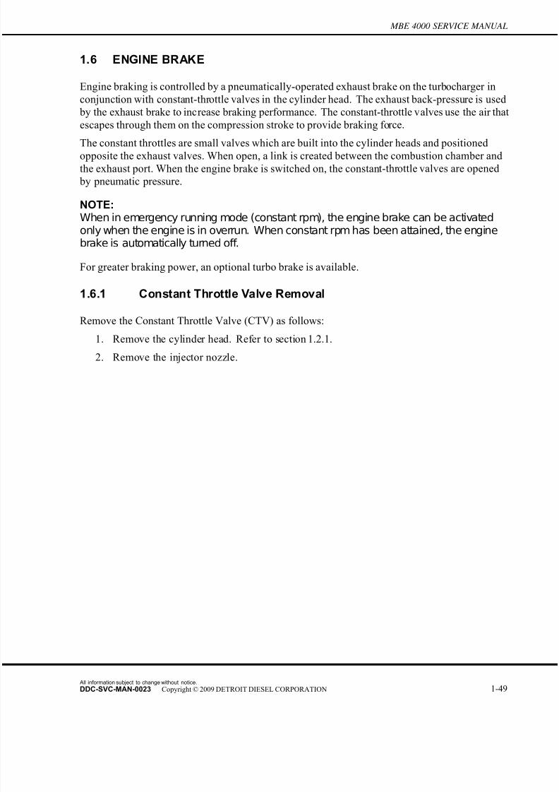
7/22/2019 Manual Mbe 4000 Taller
http://slidepdf.com/reader/full/manual-mbe-4000-taller 93/630
MBE 4000 SERVICE MANUAL
1.6 ENGINE BRAKE
Engine braking is controlled by a pneumatically-operated exhaust brake on the turb ocharger in
conjunction with constant-throttle valves in the cylinder head. The exhaust back-pressure is used
by the exhaust brake to increase braking performance. The constant-throttle valves use the air that
escapes through them on the compression stroke to provide braking force.
The constant throttles are small valves which are built into the cylinder heads and positioned
opposite the exhaust valves. When open, a link is created between the combustion chamber and
the exhaust port. When the engine brake is switched on, the constant-throttle valves are opened
by pneumatic pressure.
NOTE:When in emergency running mode (constant rpm), the engine brake can be activatedonly when the engine is in overrun. When constant rpm has been attained, the enginebrake is automatically turned off.
For greater braking power, an optional turbo brake is available.
1.6.1 Constant Throttle Valve Removal
Remove the Constant Throttle Valve (CTV) as follows:
1. Remove the cylinder head. Refer to section 1.2.1.
2. Remove the injector nozzle.
All information subject to change without notice.
DDC-SVC-MAN-0023 Copyright © 2009 DETROIT DIESEL CORPORATION 1-49
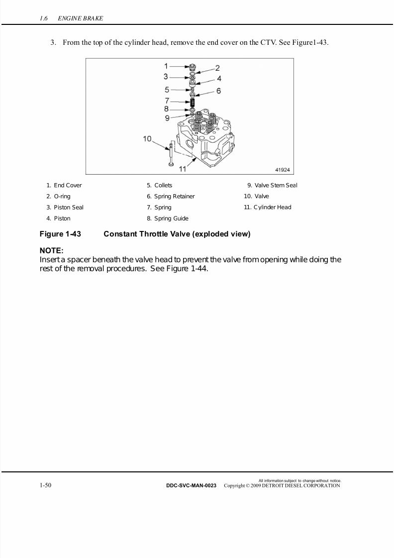
7/22/2019 Manual Mbe 4000 Taller
http://slidepdf.com/reader/full/manual-mbe-4000-taller 94/630
1.6 ENGINE BRAKE
3. From the top of the cylinder head, remove the end cover on the CTV. See Figure 1-43.
1. End Cover 5. Collets 9. Valve Stem Seal
2. O-ring 6. Spring Retainer 10. Valve
3. Piston Seal 7. Spring 11. Cylinder Head
4. Piston 8. Spring Guide
Figure 1-43 Constant Throttle Valve (exploded view)
NOTE:Inserta spacer beneath the valve head to prevent the valve fromopening while doing therest of the removal procedures. See Figure 1-44.
All information subject to change without notice.
1-50 DDC-SVC-MAN-0023 Copyright © 2009 DETROIT DIESEL CORPORATION
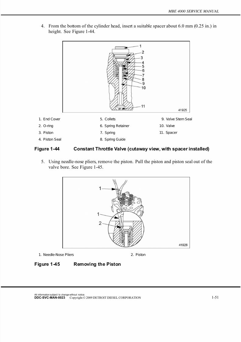
7/22/2019 Manual Mbe 4000 Taller
http://slidepdf.com/reader/full/manual-mbe-4000-taller 95/630
MBE 4000 SERVICE MANUAL
4. From the bottom of the cylinder head, insert a suitable spacer about 6.0 mm (0.25 in.) in
height. See Figure 1-44.
1. End Cover 5. Collets 9. Valve Stem Seal
2. O-ring 6. Spring Retainer 10. Valve
3. Piston 7. Spring 11. Spacer
4. Piston Seal 8. Spring Guide
Figure 1-44 Constant Throttle Valve (cutaway view, with spacer installed)
5. Using needle-nose pliers, remove the piston. Pull the piston and piston seal out of the
valve bore. See Figure 1-45.
1. Needle-Nose Pliers 2. Piston
Figure 1-45 Removing the Piston
All information subject to change without notice.
DDC-SVC-MAN-0023 Copyright © 2009 DETROIT DIESEL CORPORATION 1-51

7/22/2019 Manual Mbe 4000 Taller
http://slidepdf.com/reader/full/manual-mbe-4000-taller 96/630
1.6 ENGINE BRAKE
6. Inspect the piston and piston seal for damage and signs of wear. If necessary, replace
the piston and piston seal.
7. Insert the CTV spring remover (J-46401) down onto the spring retainer. Remove the
collets with a magnetic pin. See Figure 1-46.
1. Collets 2. Spring Retainer 3. Spring
Figure 1-46 Compressing the Spring
8. Relieve the pressure on the spring. Remove the spring retainer, spring and spring guide.
For ease of installation, mark the spring retainer and spring guide with a paint pen.
9. Turn over the cylinder head. From the bottom of the cylinder head, draw out the valve and
spacer. For ease of installation, mark the valve with a paint pen.
10. Using a small hook, remove and discard the valve stem seal.
NOTE:Always replace the valve stem seal whenever the constant-throttle valve is removed.
11. Repeat this procedure for each constant-throttle valve.
1.6.2 Constant Throttle Valve Installation
Install the Constant Throttle Valve (CTV) as follows:
1. Lubricate the valve stem with a light coating of clean engine oil. From the bottom of thecylinder head, push the valve, as marked on removal, into the valve bore. See Figure 1-43.
NOTE:Insert a spacer beneath the valve head to prevent the valve from opening while installingthe valve spring and piston.
2. Insert a suita ble spacer about 6.0 mm (0.25 in.) in height. See Figure 1-44.
All information subject to change without notice.
1-52 DDC-SVC-MAN-0023 Copyright © 2009 DETROIT DIESEL CORPORATION

7/22/2019 Manual Mbe 4000 Taller
http://slidepdf.com/reader/full/manual-mbe-4000-taller 97/630
MBE 4000 SERVICE MANUAL
3. Install a new seal on the valve stem.
[a] With the fingers, press the seal onto the valve stem past the indentation that houses
the collets when the valve is installed.
[b] Insert the spring guide over the end of the valve stem and push down until the spring
guide bottoms out.
4. From the top of the cylinder head, fit the spring and spring retainer, as marked on removal,onto the valve stem.
5. Push the spring down with the CTV spring remover and insert the collets into the spring
retainer. Push until they lock into place.
6. Install the piston and seal, as removed. Be careful not to damage the seal on installation.
See Figure 1-45.
7. From the bottom of the cylinder head, remove the spacer.
8. From the top of the cylinder head, install a new O-ring on the end cover.
9. Install the end cover.
10. Install the injector nozzle.
11. Install the cylinder head. Refer to section 1.2.1.
12. Repeat this procedure for each constant-throttle valve.
1.6.3 Constant Throttle Valve Solenoid Removal
A Kent-Moore tool, CTV solenoid socket (J–47398) is required for this procedure.
Perform the following to remove the CTV solenoid:
1. Remove the lower exhaust manifold heat shield.
1. EP V Harness Connector 2. Wirinig Harness Bracket
Figure 1-47 CTV Solenoid Removal
All information subject to change without notice.
DDC-SVC-MAN-0023 Copyright © 2009 DETROIT DIESEL CORPORATION 1-53
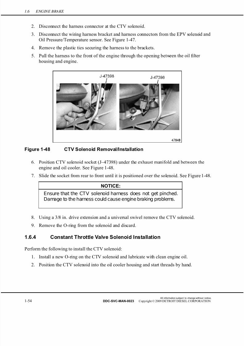
7/22/2019 Manual Mbe 4000 Taller
http://slidepdf.com/reader/full/manual-mbe-4000-taller 98/630
1.6 ENGINE BRAKE
2. Disconnect the harness connector at the CTV solenoid.
3. Disconnect the wiring harness bracket and harness connectors from the EPV solenoid and
Oil Pressure/Temperature sensor. See Figure 1-47.
4. Remove the plastic ties securing the harness to the brackets.
5. Pull the harness to the front of the engine through the opening between the oil filter
housing and engine.
Figure 1-48 CTV Solenoid Removal/Installation
6. Position CTV solenoid socket (J–47398) under the exhaust manifold and between the
engine and oil cooler. See Figure 1-48.
7. Slide the socket from rear to front until it is positioned over the solenoid. See Figure 1-48.
NOTICE:
Ensure that the CTV solenoid harness does not get pinched.Damage to the harness could cause engine braking problems.
8. Using a 3/8 in. drive extension and a universal swivel remove the CTV solenoid.
9. Remove the O-ring from the solenoid and discard.
1.6.4 Constant Throttle Valve Solenoid Installation
Perform the following to install the CTV solenoid:
1. Install a new O-ring on the CTV solenoid and lubricate with clean engine oil.
2. Position the CTV solenoid into the oil cooler housing and start threads by hand.
All information subject to change without notice.
1-54 DDC-SVC-MAN-0023 Copyright © 2009 DETROIT DIESEL CORPORATION
7/22/2019 Manual Mbe 4000 Taller
http://slidepdf.com/reader/full/manual-mbe-4000-taller 99/630
MBE 4000 SERVICE MANUAL
NOTICE:
Ensure that the CTV solenoid harness does not get pinched.Damage to the harness could cause engine braking problems.
3. Using a 3/8 in. drive extension and a universal swivel, torque the CTV solenoid to
35 N·m (26 lb·ft).4. Connect the harness connectors to the CTV solenoid, Oil Pressure/Temperature Sensor,
and EPV solenoid. Secure harness with nylon tie straps.
5. Install the removed lower exhaust manifold heat shield. Torque the bolts to 25 N·m (18
lb·ft).
All information subject to change without notice.
DDC-SVC-MAN-0023 Copyright © 2009 DETROIT DIESEL CORPORATION 1-55
7/22/2019 Manual Mbe 4000 Taller
http://slidepdf.com/reader/full/manual-mbe-4000-taller 100/630
1.7 FRONT RADIAL SEAL
1.7 FRONT RADIAL SEAL
Two Kent-Moore tools are required for this procedure:
□ Front Seal Puller (J–47272)
□ Front Seal Installer (J–45391)
1.7.1 Front Radial Seal Removal
Remove the front radial seal as follows:
1. Park the vehicle on a level spot, set the parking brakes, and chock the tires.
PERSONAL INJURY
To avoid injury before starting and running the engine,
ensure the vehicle is parked on a level surface, parkingbrake is set, and the wheels are blocked.
2. Tilt the hood.
3. From underneath the front of the engine, remove the bumper beam. Push the support angle
bracket fairing down to create an opening in the bumper.
4. Remove the vibration damper from the engine through the opening in the bumper.
Refer to section 1.12.1.
5. Check the seal for wear at the places where it contacts the crankshaft.
All information subject to change without notice.
1-56 DDC-SVC-MAN-0023 Copyright © 2009 DETROIT DIESEL CORPORATION
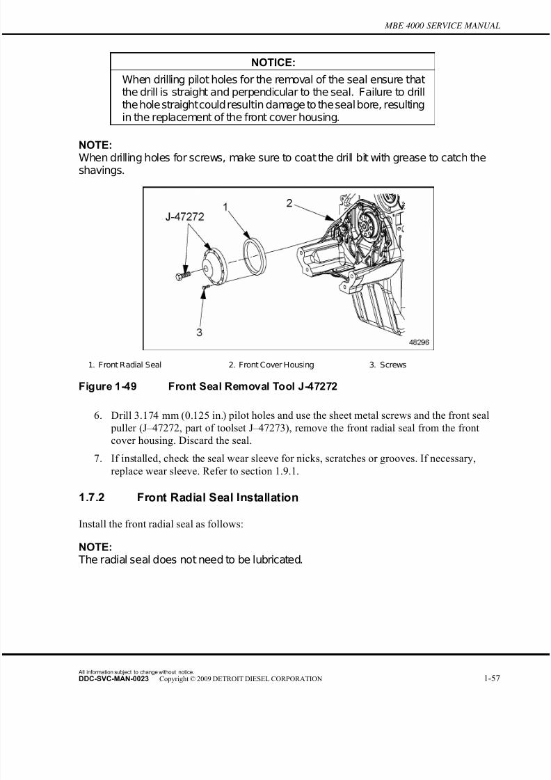
7/22/2019 Manual Mbe 4000 Taller
http://slidepdf.com/reader/full/manual-mbe-4000-taller 101/630
MBE 4000 SERVICE MANUAL
NOTICE:
When drilling pilot holes for the removal of the seal ensure thatthe drill is straight and perpendicular to the seal. Failure to drillthe hole straightcouldresultin damage to theseal bore, resultingin the replacement of the front cover housing.
NOTE:When drilling holes for screws, make sure to coat the drill bit with grease to catch theshavings.
1. Front Radial Seal 2. Front Cover Housing 3. Screws
Figure 1-49 Front Seal Removal Tool J-47272
6. Drill 3.174 mm (0.125 in.) pilot holes and use the sheet metal screws and the front seal
puller (J–47272, part of toolset J–47273), remove the front radial seal from the front
cover housing. Discard the seal.
7. If installed, check the seal wear sleeve for nicks, scratches or grooves. If necessary,
replace wear sleeve. Refer to section 1.9.1.
1.7.2 Front Radial Seal Installation
Install the front radial seal as follows:
NOTE: The radial seal does not need to be lubricated.
All information subject to change without notice.
DDC-SVC-MAN-0023 Copyright © 2009 DETROIT DIESEL CORPORATION 1-57

7/22/2019 Manual Mbe 4000 Taller
http://slidepdf.com/reader/full/manual-mbe-4000-taller 102/630
1.7 FRONT RADIAL SEAL
1. Clean the sealing surfaces on the cover and the cylinder block.
NOTE: The seal installation is the same for a standard size and oversize front radial seal. Thefront standard size radial seal has an inside diameter of 100.0 mm (3.94 in.). Theoversize radial seal has an inside diameter of 105.0 mm (4.13 in.).
2. Slide the seal over the center guide (J–45391–2, part of toolset J–45391 and service kit
J–47273). Place the guide on the front of the crankshaft. Fit the front seal installer
(J–45391–1, part of toolset J–45391 and service kit J–47273) over the guide and tap it
into the front cover housing until it bottoms. Visually check the seal and sealing lip for
correct installation. See Figure 1-50.
1. Front Radial Seal 2. Front of Crankshaft
Figure 1-50 Front Radial Seal Location
3. Install the vibration damper on the crankshaft. Refer to section 1.12.2.
4. Install the three drive belts.
5. Install the support angle bracket fairing. Install the bumper beam.
All information subject to change without notice.
1-58 DDC-SVC-MAN-0023 Copyright © 2009 DETROIT DIESEL CORPORATION

7/22/2019 Manual Mbe 4000 Taller
http://slidepdf.com/reader/full/manual-mbe-4000-taller 103/630
MBE 4000 SERVICE MANUAL
PERSONAL INJURY
To avoid injury before starting and running the engine,ensure the vehicle is parked on a level surface, parking
brake is set, and the wheels are blocked.
ENGINE EXHAUST
To avoid injury from inhaling engine exhaust, alwaysoperate the engine in a well-ventilated area. Engineexhaust is toxic.
6. Start the engine and check the engine oil pressure at idle. Engine oil pressure at idle
should be at least 50 kPa (7 psi). Looks for any oil leaks, repair as necessary.
7. Close the hood, and remove the chocks from the tires.
All information subject to change without notice.
DDC-SVC-MAN-0023 Copyright © 2009 DETROIT DIESEL CORPORATION 1-59

7/22/2019 Manual Mbe 4000 Taller
http://slidepdf.com/reader/full/manual-mbe-4000-taller 104/630
1.8 REAR RADIAL SEAL
1.8 REAR RADIAL SEAL
The below listed special tools are required for this procedure.
□ Rear Seal Puller, J–46188 (part of service kit J–47273)
□ Rear Seal Puller (std seal), J–45393–A (part of service kit J–47273)
□ Front/Rear Oversize Seal Installer Kit, J–47067 (part of service kit J–47273)
□ Seal and Wear Sleeve Service Kit, J-47273
1.8.1 Rear Radial Seal Removal
Remove the rear radial seal as follows:
1. Remove the flywheel. Refer to section 1.13.1.
1. Rear R adial Seal 2. Flywheel Housing 3. End of C rankshaft
Figure 1-51 Rear Radial Seal Removal
NOTICE:
When drilling pilot holes for the removal of seal ensure that thedrill is straight and perpendicular to the seal. Failure to drill thehole straightcould resultin damage to the seal bore, resulting inthe replacement of the flywheel housing.
NOTE:When drilling holes for screws, make sure to coat the drill bit with grease to catch theshavings.
2. Drill 3.174 mm (0.125 in.) pilot holes and use the sheet metal screws and the rear seal
puller J–46188 (part of service kit J–47273), remove the rear radial seal from the flywheel
housing. Discard the seal. See Figure 1-51.
All information subject to change without notice.
1-60 DDC-SVC-MAN-0023 Copyright © 2009 DETROIT DIESEL CORPORATION
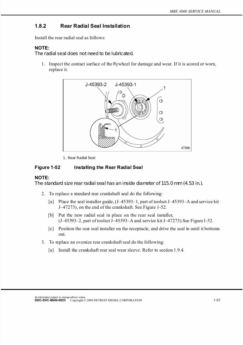
7/22/2019 Manual Mbe 4000 Taller
http://slidepdf.com/reader/full/manual-mbe-4000-taller 105/630
MBE 4000 SERVICE MANUAL
1.8.2 Rear Radial Seal Installation
Install the rear radial seal as follows:
NOTE: The radial seal does not need to be lubricated.
1. Inspect the contact surface of the flywheel for damage and wear. If it is scored or worn,
replace it.
1. Rear Radial Seal
Figure 1-52 Installing the Rear Radial Seal
NOTE:
The standard size rear radial seal has an inside diameter of 115.0 mm (4.53 in.).
2. To replace a standard rear crankshaft seal do the following:
[a] Place the seal installer guide, (J–45393–1, part of toolset J–45393–A and service kit
J–47273), on the end of the crankshaft. See Figure 1-52.
[b] Put the new radial seal in place on the rear seal installer,
(J–45393–2, part of toolset J–45393–A and service kit J–47273).See Figure 1-52.
[c] Position the rear seal installer on the receptacle, and drive the seal in until it bottoms
out.
3. To replace an oversize rear crankshaft seal do the following:
[a] Install the crankshaft rear seal wear sleeve. Refer to section 1.9.4.
All information subject to change without notice.
DDC-SVC-MAN-0023 Copyright © 2009 DETROIT DIESEL CORPORATION 1-61

7/22/2019 Manual Mbe 4000 Taller
http://slidepdf.com/reader/full/manual-mbe-4000-taller 106/630
1.8 REAR RADIAL SEAL
[b] Install two seal guide pins (J-47067–4, part of toolset J–47067 and service kit
J-47273). See detail “B” in Figure 1-53.
1. Flywheel Housing 2. Crankshaft 3. Seal
Figure 1-53 Rear Oversize Crankshaft Seal Installation
NOTE: The oversize rear radial seal has in inside diameter of 120.0 mm (4.72 in.).
[c] Put the new radial seal in place on the rear seal installer,
(J–47067–1, part of toolset J–47067 and service kit J–47273). See detail “C” in Figure
1-53.
[d] Slide the seal installer (J–47067–1, part of toolset J–47067 and service kit J–47273),
over the guide pins (J–47067–4) part of toolset J–47067 and service kit J–47273) and
position the seal into the flywheel housing. See detail “D” in Figure 1-53.
[e] Install the forcing screw (24833, part of toolset J–47067 and service kit J–47273) and
crossbar (26603, part of toolset J–47067 and service kit J–47273) onto the guide pins.
See detail “D” in Figure 1-53.
[f] Install the seal by turning the forcing screw until the tool bottoms on the butt of the crankshaft.
[g] Remove the tool and visually check the seal and sealing lip for correct installation.
[h] Install the flywheel. Refer to section 1.13.2.
All information subject to change without notice.
1-62 DDC-SVC-MAN-0023 Copyright © 2009 DETROIT DIESEL CORPORATION
7/22/2019 Manual Mbe 4000 Taller
http://slidepdf.com/reader/full/manual-mbe-4000-taller 107/630
MBE 4000 SERVICE MANUAL
1.9 CRANKSHAFT SEAL WEAR SLEEVE
The crankshaft seal wear sleeve is used on the front or rear of the crankshaft in conju nction
with an oversize seal.
The below listed special tools are required for this procedure:
□ Seal and Wear Sleeve Service Kit, (J-47273)□ Universal Driver Handle, (J–8092, part of toolset J-47273)
□ Front/Rear Wear Sleeve Installer, (J-45989, part of service kit J–47273)
□ Front/Rear Wear Sleeve Installer, (J-47271, part of service kit J–47273)
1.9.1 Front Crankshaft Seal Wear Sleeve Removal
Perform the following to remove the front crankshaft seal wear sleeve:
1. Park the vehicle on a level spot, set the parking brakes, and chock the tires.
2. Tilt the hood.
3. From underneath the front of the engine, remove the bumper beam. Push the support angle
bracket fairing down to create an opening in the bumper.
4. Remove the vibration damper and pulley from the engine through the opening in the
bumper. Refer to section 1.12.1.
5. Remove the front radial seal. Refer to section 1.7.1.
6. Clean the seal wear sleeve seat area on the crankshaft.
7. Assemble the front seal wear sleeve removal tool (J-45989, part of service kit J–47273).
See Figure 1-54.
1. Seal Wear Sleeve
Figure 1-54 Front Seal Wear Sleeve Removal Tool J-45989
All information subject to change without notice.
DDC-SVC-MAN-0023 Copyright © 2009 DETROIT DIESEL CORPORATION 1-63

7/22/2019 Manual Mbe 4000 Taller
http://slidepdf.com/reader/full/manual-mbe-4000-taller 108/630
1.9 CRANKSHAFT SEAL WEAR SLEEVE
NOTE:Ensure that the forcing screw is coated with the supplied high-pressure grease.
8. Install the assembled tool J–45989 into place by sliding from the bottom up along the rear
of the seal wear sleeve. See Figure 1-55.
Figure 1-55 Removing the Front Seal Wear Sleeve
9. Turn the forcing screw in a slow and continuous motion until the seal wear sleeve is
removed. Discard the seal wear sleeve.
NOTE:
Once the seal wear sleeve is fully removed the tool will drop. Use care to support thetool during the removal procedure.
1.9.2 Front Crankshaft Seal Wear Sleeve Installation
Perform the following to install the front crankshaft seal wear sleeve:
1. Clean the seal wear sleeve seat area on the crankshaft.
NOTICE:
Be sure to heat the newseal wear sleeve as evenly as possible.
If available, an oven should be used. Uneven heating of the sealwearsleeve can weaken the material andreduce the service life.
2. Install the seal wear sleeve with the rounded edge toward the inside of the seal wear sleeve
installer tool (J–47271, part of toolset J-47273). Heat the tool and sleeve together in
an oven to a maximum of 150°C (302°F).
All information subject to change without notice.
1-64 DDC-SVC-MAN-0023 Copyright © 2009 DETROIT DIESEL CORPORATION
7/22/2019 Manual Mbe 4000 Taller
http://slidepdf.com/reader/full/manual-mbe-4000-taller 109/630
MBE 4000 SERVICE MANUAL
BURNS
To avoid injury from burning, use lifting tools andheat-resistant gloves when handling heated components.
3. Remove the tool and sleeve from the oven and thread driver handle (J–8092,part of toolset
J-47273) into the seal wear sleeve installer tool (J–47271, part of toolset J-47273).
NOTICE:
Ensure that the rounded edge of the seal wear sleeve faces outand isflush with the crankshaft. The installer tool guarantees theseal wear sleeve position onto the crankshaft. Failing to use thecorrect tool may affect the service life of the seal.
4. Drive the seal wear sleeve onto the front of the crankshaft.
5. Wait until the seal wear sleeve cools to room temperature before installing the oversize
radial seal. Refer to section 1.7.2 to install the front oversize radial seal.
1.9.3 Rear Crankshaft Seal Wear Sleeve Removal
Perform the following to remove the rear crankshaft seal wear sleeve:
1. Remove the flywheel. Refer to section 1.13.1.
1. Flywheel
Figure 1-56 Rear Seal Wear Sleeve Removal
All information subject to change without notice.
DDC-SVC-MAN-0023 Copyright © 2009 DETROIT DIESEL CORPORATION 1-65

7/22/2019 Manual Mbe 4000 Taller
http://slidepdf.com/reader/full/manual-mbe-4000-taller 110/630
1.9 CRANKSHAFT SEAL WEAR SLEEVE
2. Position the assembled seal wear sleeve removal tool (J–47271, part of toolset J-47273)
ensuring that the plate is positioned behind the lip of the seal wear sleeve. See Figure 1-56.
NOTE:Lubricate the forcing screw with the supplied high-pressure lubricant.
3. Turn the forcing screw until the seal wear sleeve has been removed from thefl
ywheel.Discard the seal wear sleeve. See Figure 1-57.
1. Seal Wear Sleeve 2. Flywheel
Figure 1-57 Rear Seal Wear Sleeve Removal Using Tool J-45989
1.9.4 Rear Crankshaft Seal Wear Sleeve Installation
Perform the following to install the rear crankshaft seal wear sleeve:
1. Remove the flywheel. Refer to section 1.13.
2. Install the seal wear sleeve with the rounded edge toward the inside of the seal wear sleeve
installer tool (J–47271, part of toolset J-47273). Heat the tool and sleeve together in
an oven to a maximum of 150°C (302°F).
All information subject to change without notice.
1-66 DDC-SVC-MAN-0023 Copyright © 2009 DETROIT DIESEL CORPORATION
7/22/2019 Manual Mbe 4000 Taller
http://slidepdf.com/reader/full/manual-mbe-4000-taller 111/630
MBE 4000 SERVICE MANUAL
BURNS
To avoid injury from burning, use lifting tools andheat-resistant gloves when handling heated components.
NOTICE:
Be sure to heatthe new seal wear sleeve as evenly as possible.If available, an oven should be used. Uneven heating of the sealwearsleeve can weaken the material and reduce the service life.
3. Remove the tool and wear sleeve from the oven and thread driver handle (J–8092, part of
toolset J-47273) into the seal wear sleeve installer tool (J–47271, part of toolset J-47273).
NOTICE:
Ensure that the rounded edge of the seal wear sleeve faces outand isflush with the crankshaft. The installer tool guarantees theseal wear sleeve position onto the crankshaft. Failing to use thecorrect tool may affect the service life of the seal.
4. Drive the seal wear sleeve onto the flywheel hub area.
5. Wait until the seal wear sleeve cools to room temperature before installing the oversize
radial seal. Refer to section 1.7.2 to install the front oversize radial seal.
All information subject to change without notice.
DDC-SVC-MAN-0023 Copyright © 2009 DETROIT DIESEL CORPORATION 1-67
7/22/2019 Manual Mbe 4000 Taller
http://slidepdf.com/reader/full/manual-mbe-4000-taller 112/630
1.10 CRANKSHAFT ASSEMBLY
1.10 CRANKSHAFT ASSEMBLY
The crankshaft is precision-forged with seven main bearings and eight custom-forged counter
weights, and a vibration damper at the front end. For an exploded view of the crankshaft, main
bearings, and main bearing caps, see Figure 1-58.
1. Crankshaft 5. Lower Bearing Shell (center)
2. Upper Bearing S hell(s) 6. Main Bearing C ap(s)
3. Upper Bearing S hell (center) 7. Main Bearing C ap (center)
4. Lower Bearing S hell(s) 8. Main Bearing C ap Bolt
Figure 1-58 Crankshaft, Main Bearings, and Main Bearing Caps
1.10.1 Crankshaft Removal
Remove the crankshaft as follows:
All information subject to change without notice.
1-68 DDC-SVC-MAN-0023 Copyright © 2009 DETROIT DIESEL CORPORATION
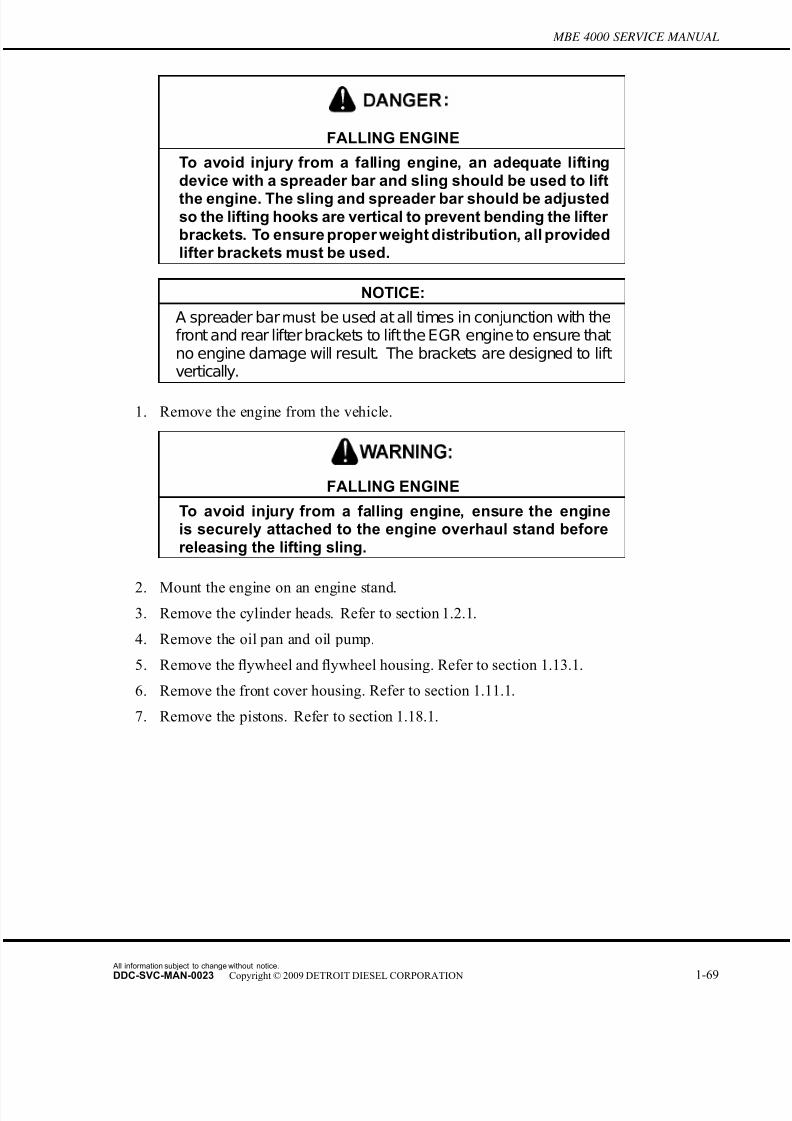
7/22/2019 Manual Mbe 4000 Taller
http://slidepdf.com/reader/full/manual-mbe-4000-taller 113/630
MBE 4000 SERVICE MANUAL
FALLING ENGINE
To avoid injury from a falling engine, an adequate liftingdevice with a spreader bar and sling should be used to lift
the engine. The sling and spreader bar should be adjustedso the lifting hooks are vertical to prevent bending the lifter brackets. To ensure proper weight distribution, all providedlifter brackets must be used.
NOTICE:
A spreader bar must be used at all times in conjunction with thefront and rear lifter brackets to liftthe EGR engine to ensure thatno engine damage will result. The brackets are designed to liftvertically.
1. Remove the engine from the vehicle.
FALLING ENGINE
To avoid injury from a falling engine, ensure the engineis securely attached to the engine overhaul stand beforereleasing the lifting sling.
2. Mount the engine on an engine stand.
3. Remove the cylinder heads. Refer to section 1.2.1.
4. Remove the oil pan and oil pump.
5. Remove the flywheel and flywheel housing. Refer to section 1.13.1.
6. Remove the front cover housing. Refer to section 1.11.1.
7. Remove the pistons. Refer to section 1.18.1.
All information subject to change without notice.
DDC-SVC-MAN-0023 Copyright © 2009 DETROIT DIESEL CORPORATION 1-69

7/22/2019 Manual Mbe 4000 Taller
http://slidepdf.com/reader/full/manual-mbe-4000-taller 114/630
1.10 CRANKSHAFT ASSEMBLY
8. Turn the crankshaft until the marked gear teeth on the camshaft gear line up with the
marked tooth on the crankshaft gear. See Figure 1-59.
1. Camshaft Gear 2. Crankshaft Gear 3. Dowel Pin
Figure 1-59 Aligning the Marked Gear Teeth
9. Remove the crankshaft gear from the crankshaft. Refer to section 1.10.3.
10. Mark the order of the main bearing caps, then remove the main bearing-cap bolts.
See Figure 1-60.
Figure 1-60 Removal Order , Main Bearing Cap Bolts
11. Loosen the main bearing caps with a plastic hammer, if necessary. Remove the main
bearing caps.
All information subject to change without notice.
1-70 DDC-SVC-MAN-0023 Copyright © 2009 DETROIT DIESEL CORPORATION

7/22/2019 Manual Mbe 4000 Taller
http://slidepdf.com/reader/full/manual-mbe-4000-taller 115/630
MBE 4000 SERVICE MANUAL
FALLING COMPONENT
To avoid injury from a falling component, ensure a proper lifting device is used.
12. Attach a suitable hoist to the crankshaft, using flexible straps to hold the crankshaft
without bending or scratching it. Then lift the crankshaft out of the block. See Figure 1-61.
1. Crankshaft 3. Hoisting Chain
2. Flexible Straps 4. Engine Stand
Figure 1-61 Attaching the Hoist
All information subject to change without notice.
DDC-SVC-MAN-0023 Copyright © 2009 DETROIT DIESEL CORPORATION 1-71

7/22/2019 Manual Mbe 4000 Taller
http://slidepdf.com/reader/full/manual-mbe-4000-taller 116/630
1.10 CRANKSHAFT ASSEMBLY
13. Lift the crankshaft out of the cylinder block. Make sure the crankshaft doesn't twist from
side to side. See Figure 1-62.
1. Crankshaft 3. Hook of Hoisting Chain
2. Flexible Straps 4. Cylinder Block
Figure 1-62 Lifting the Crankshaft
[a] Lower the crankshaft gently onto a flat surface covered with clean cardboard.
[b] Remove the hoist.
14. Mark each upper bearing shell and its corresponding race before removing the bearing
shells from the crankcase.
15. Check all parts for wear or damage. Measure the various crankshaft specifications.
Refer to section 1.10.1.3.
1.10.1.1 Crankshaft Measuring and Inspection
Inspect the crankshaft as follows:
1. Remove the crankshaft. Refer to section 1.10.1.
2. Clean the crankshaft with a chamois.
3. Check the crankshaft for condition. If cracks or fissures are found, replace the crankshaft.
4. Using a hardness tester, test the hardness of the journals. Each journal must pass thehardness test at two thirds of its circumference. If it doesn't, either replace the crankshaft,
or have it re-hardened.
[a] Place a hard base underneath the bearing journal to be tested.
All information subject to change without notice.
1-72 DDC-SVC-MAN-0023 Copyright © 2009 DETROIT DIESEL CORPORATION
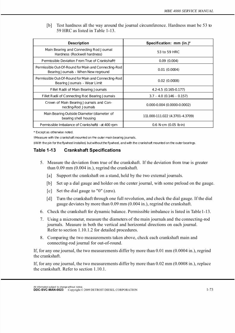
7/22/2019 Manual Mbe 4000 Taller
http://slidepdf.com/reader/full/manual-mbe-4000-taller 117/630
MBE 4000 SERVICE MANUAL
[b] Test hardness all the way around the journal circumference. Hardness must be 53 to
59 HRC as listed in Table 1-13.
Description Specification: mm (in.)*
Main Bearing and Connecting Rod J ournal
Hardness (Rockwell hardness)53 to 59 HRC
Permissible Deviation From True of Crankshaft† 0.09 (0.004)
Permissible Out-Of-Round for Main and Connecting-Rod
Bearing J ournals - When New reground0.01 (0.0004)
Permissible Out-Of-Round for Main and Connecting-Rod
Bearing J ournals - Wear Limit0.02 (0.0008)
Fillet Radii of Main Bearing J ournals 4.2-4.5 (0.165-0.177)
Fillet Radii of Connecting Rod Bearing J ournals 3.7 - 4.0 (0.146 - 0.157)
Crown of Main Bearing J ournals and Con-
necting-Rod J ournals0.000-0.004 (0.0000-0.0002)
Main Bearing Outside Diameter (diameter of
bearing shell housing 111.000-111.022 (4.3701-4.3709)
Permissible Imbalance of Crankshaft‡ -at 400 rpm 0.6 N·cm (0.05 lb·in)
* Except as otherwise noted.
†Measure with the crankshaft mounted on the outer main bearing journals.
‡With the pin for theflywheel installed, but withoutthe flywheel, and with the crankshaft mounted on the outer bearings.
Table 1-13 Crankshaft Specifications
5. Measure the deviation from true of the crankshaft. If the deviation from true is greater
than 0.09 mm (0.004 in.), regrind the crankshaft.
[a] Support the crankshaft on a stand, held by the two external journals.
[b] Set up a dial gauge and holder on the center journal, with some preload on the gauge.
[c] Set the dial gauge to "0" (zero).
[d] Turn the crankshaft through one full revolution, and check the dial gauge. If the dial
gauge deviates by more than 0.09 mm (0.004 in.), regrind the crankshaft.
6. Check the crankshaft for dynamic balance. Permissible imbalance is listed in Table 1-13.
7. Using a micrometer, measure the diameters of the main journals and the connecting-rod
journals. Measure in both the vertical and horizontal directions on each journal.
Refer to section 1.10.1.2 for detailed procedures.
8. Comparing the two measurements taken above, check each crankshaft main and
connecting-rod journal for out-of-round.
If, for any one journal, the two measurements differ by more than 0.01 mm (0.0004 in.), regrind
the crankshaft.
If, for any one journal, the two measurements differ by more than 0.02 mm (0.0008 in.), replace
the crankshaft. Refer to section 1.10.1.
All information subject to change without notice.
DDC-SVC-MAN-0023 Copyright © 2009 DETROIT DIESEL CORPORATION 1-73

7/22/2019 Manual Mbe 4000 Taller
http://slidepdf.com/reader/full/manual-mbe-4000-taller 118/630
1.10 CRANKSHAFT ASSEMBLY
Listed in Table 1-14 are the permissible ranges at the various repair stages.
Size: mm (in.) Main Bearing Journal
Diameter: mm (in.)
Connecting-Rod Bearing
Journal Diameter: mm (in.)
Standard 103.980-104.000 (4.0937-4.0945) 93.980-94.000 (3.7000-3.7007)
Undersize - 0.10 (0.004) 103.880-103.900 (4.0898-4.0905) 93.880-93.900 (3.6960-3.6968)
Undersize - 0.25 (0.010) 103.730-103.750 (4.0839-4.0846) 93.730-93.750 (3.6901-3.6909)
Undersize - 0.50 (0.020) 103.480-103.500 (4.0740-4.0748) 93.480-93.500 (3.6803-3.6811)
Undersize - 0.75 (0.030) 103.230-103.250 (4.0642-4.0650) 93.230-93.250 (3.6705-3.6712)
Undersize - 1.00 (0.040) 102.980-103.000 (4.0543-4.0551) 92.980-93.000 (3.6606-3.6614)
Table 1-14 Crankshaft Journal Diameters
9. Measure the width of all the main and connecting-rod journals. See Figure 1-63.
Listed in Table 1-15 are the permissible ranges.
1. Crankshaft 2. Hardness Tester
Figure 1-63 Journal Measurements
Type of Journal Width: mm (in.)
Main J ournal46.000-46.250
(1.8110-1.8209)
Connecting-Rod J ournal 44.5-44.6(1.752-1.756)
Table 1-15 Crankshaft Bearing Journal Width
All information subject to change without notice.
1-74 DDC-SVC-MAN-0023 Copyright © 2009 DETROIT DIESEL CORPORATION
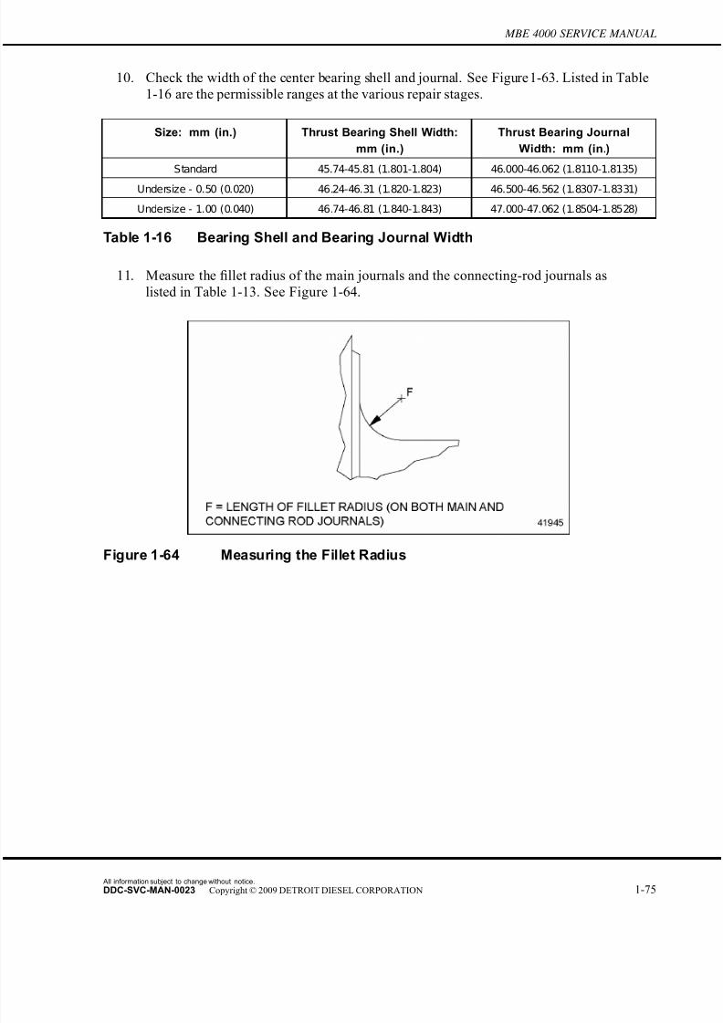
7/22/2019 Manual Mbe 4000 Taller
http://slidepdf.com/reader/full/manual-mbe-4000-taller 119/630
MBE 4000 SERVICE MANUAL
10. Check the width of the center bearing shell and journal. See Figure 1-63. Listed in Table
1-16 are the permissible ranges at the various repair stages.
Size: mm (in.) Thrust Bearing Shell Width:
mm (in.)
Thrust Bearing Journal
Width: mm (in.)
Standard 45.74-45.81 (1.801-1.804) 46.000-46.062 (1.8110-1.8135)
Undersize - 0.50 (0.020) 46.24-46.31 (1.820-1.823) 46.500-46.562 (1.8307-1.8331)
Undersize - 1.00 (0.040) 46.74-46.81 (1.840-1.843) 47.000-47.062 (1.8504-1.8528)
Table 1-16 Bearing Shell and Bearing Journal Width
11. Measure the fillet radius of the main journals and the connecting-rod journals as
listed in Table 1-13. See Figure 1-64.
Figure 1-64 Measuring the Fillet Radius
All information subject to change without notice.
DDC-SVC-MAN-0023 Copyright © 2009 DETROIT DIESEL CORPORATION 1-75
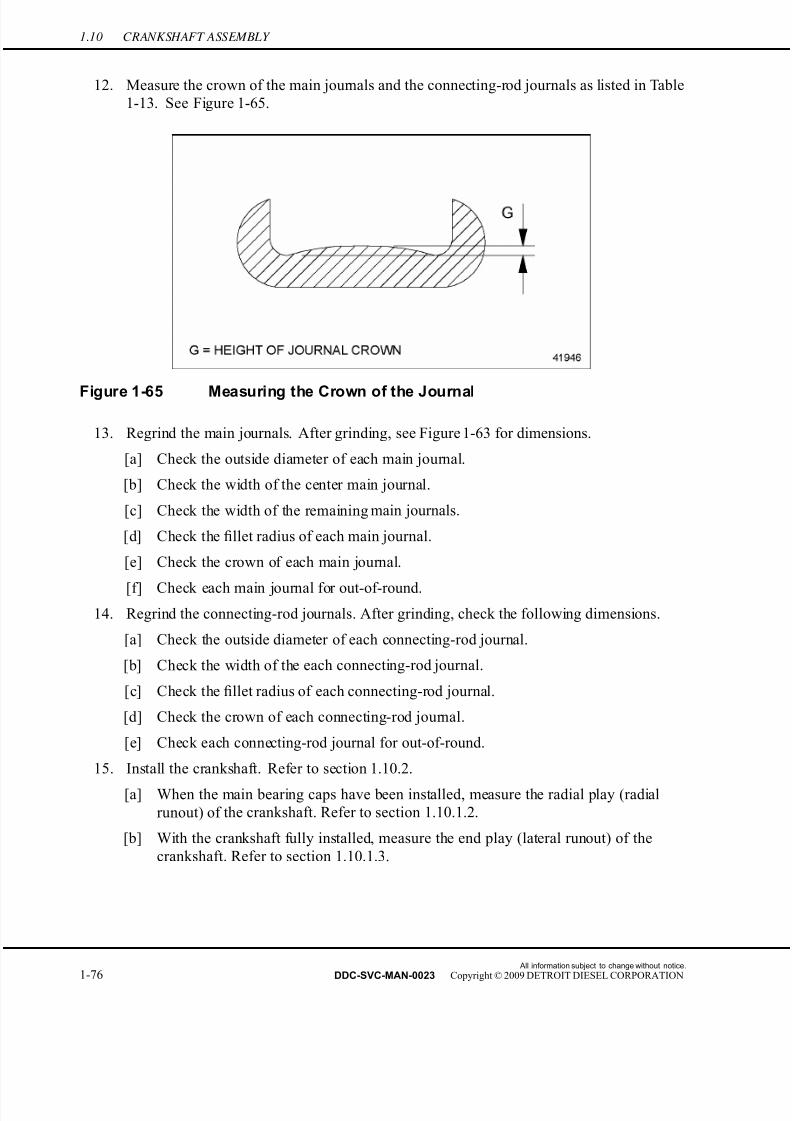
7/22/2019 Manual Mbe 4000 Taller
http://slidepdf.com/reader/full/manual-mbe-4000-taller 120/630
1.10 CRANKSHAFT ASSEMBLY
12. Measure the crown of the main journals and the connecting-rod journals as listed in Table
1-13. See Figure 1-65.
Figure 1-65 Measuring the Crown of the Journal
13. Regrind the main journals. After grinding, see Figure 1-63 for dimensions.
[a] Check the outside diameter of each main journal.
[b] Check the width of the center main journal.
[c] Check the width of the remaining main journals.
[d] Check the fillet radius of each main journal.
[e] Check the crown of each main journal.
[f] Check each main journal for out-of-round.
14. Regrind the connecting-rod journals. After grinding, check the following dimensions.
[a] Check the outside diameter of each connecting-rod journal.
[b] Check the width of the each connecting-rod journal.
[c] Check the fillet radius of each connecting-rod journal.
[d] Check the crown of each connecting-rod journal.
[e] Check each connecting-rod journal for out-of-round.
15. Install the crankshaft. Refer to section 1.10.2.
[a] When the main bearing caps have been installed, measure the radial play (radial
runout) of the crankshaft. Refer to section 1.10.1.2.
[b] With the crankshaft fully installed, measure the end play (lateral runout) of the
crankshaft. Refer to section 1.10.1.3.
All information subject to change without notice.
1-76 DDC-SVC-MAN-0023 Copyright © 2009 DETROIT DIESEL CORPORATION

7/22/2019 Manual Mbe 4000 Taller
http://slidepdf.com/reader/full/manual-mbe-4000-taller 121/630
MBE 4000 SERVICE MANUAL
1.10.1.2 Crankshaft Radial Play Checking
Check the crankshaft radial play as follows:
1. Clean the bearing races in the crankcase (cylinder block) and the bearing seats in the
bearing caps with a chamois.
NOTE: The center bearing shell halves must be mounted in the center crankcase race andbearing cap (fourth from either end).
2. Install the upper bearing shell on the bearing race in the crankcase. The locking lugs of the
bearing shells must fit into the slots in the crankcase races. See Figure 1-66.
1. Crankcase Race 3. Cylinder Block
2. Upper Bearing S hell 4. Bearing S hells Locking Lug
Figure 1-66 Installing the Upper Bearing Shell
All information subject to change without notice.
DDC-SVC-MAN-0023 Copyright © 2009 DETROIT DIESEL CORPORATION 1-77

7/22/2019 Manual Mbe 4000 Taller
http://slidepdf.com/reader/full/manual-mbe-4000-taller 122/630
1.10 CRANKSHAFT ASSEMBLY
3. Install the lower bearing shell on the bearing seat in the bearing cap. The locking lugs in
the bearing shells must fit into the grooves in the bearing cap. See Figure 1-67.
1. Main Bearing C ap 2. Lower Bearing S hell 3. Guide Pin
Figure 1-67 Installing the Lower Bearing Shell
NOTE: The guide pins on the bearing cap ensure correct seating of the cap on the crankcaserace.
All information subject to change without notice.
1-78 DDC-SVC-MAN-0023 Copyright © 2009 DETROIT DIESEL CORPORATION
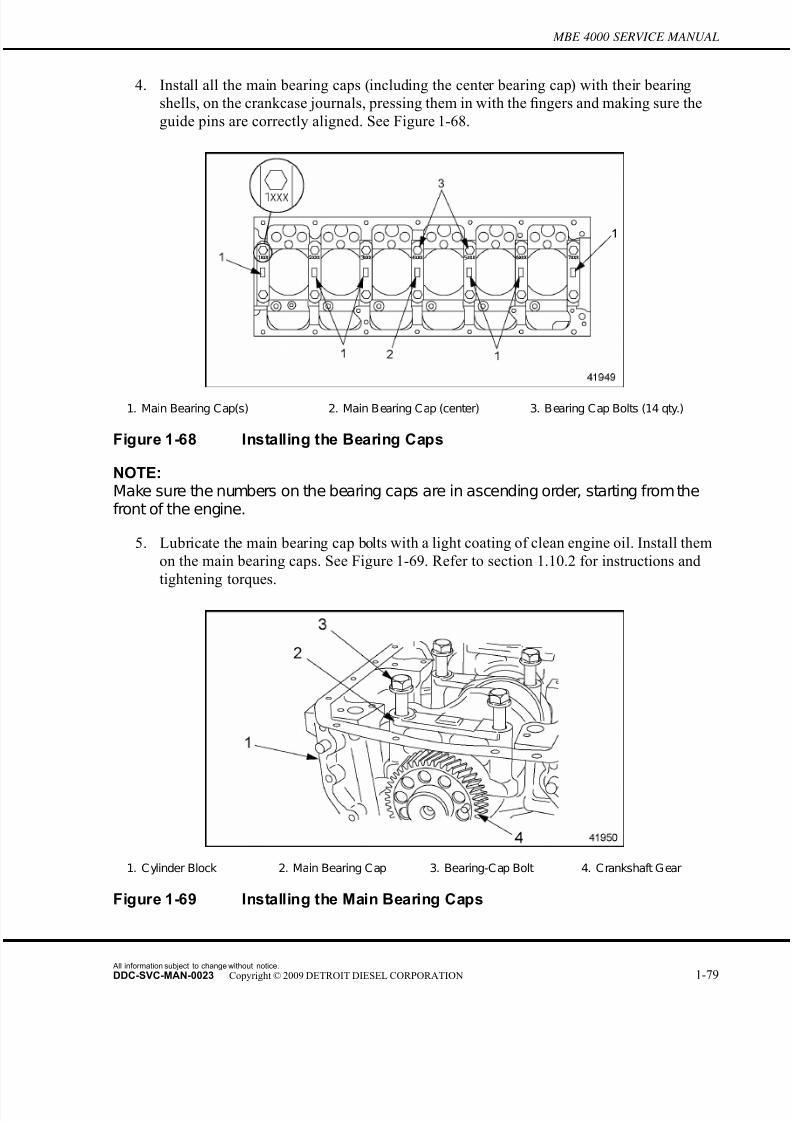
7/22/2019 Manual Mbe 4000 Taller
http://slidepdf.com/reader/full/manual-mbe-4000-taller 123/630
MBE 4000 SERVICE MANUAL
4. Install all the main bearing caps (including the center bearing cap) with their bearing
shells, on the crankcase journals, pressing them in with the fingers and making sure the
guide pins are correctly aligned. See Figure 1-68.
1. Main Bearing Cap(s) 2. Main Bearing Cap (center) 3. Bearing Cap Bolts (14 qty.)
Figure 1-68 Installing the Bearing Caps
NOTE:Make sure the numbers on the bearing caps are in ascending order, starting from thefront of the engine.
5. Lubricate the main bearing cap bolts with a light coating of clean engine oil. Install them
on the main bearing caps. See Figure 1-69. Refer to section 1.10.2 for instructions and
tightening torques.
1. Cylinder Block 2. Main Bearing Cap 3. Bearing-Cap Bolt 4. Crankshaft Gear
Figure 1-69 Installing the Main Bearing Caps
All information subject to change without notice.
DDC-SVC-MAN-0023 Copyright © 2009 DETROIT DIESEL CORPORATION 1-79
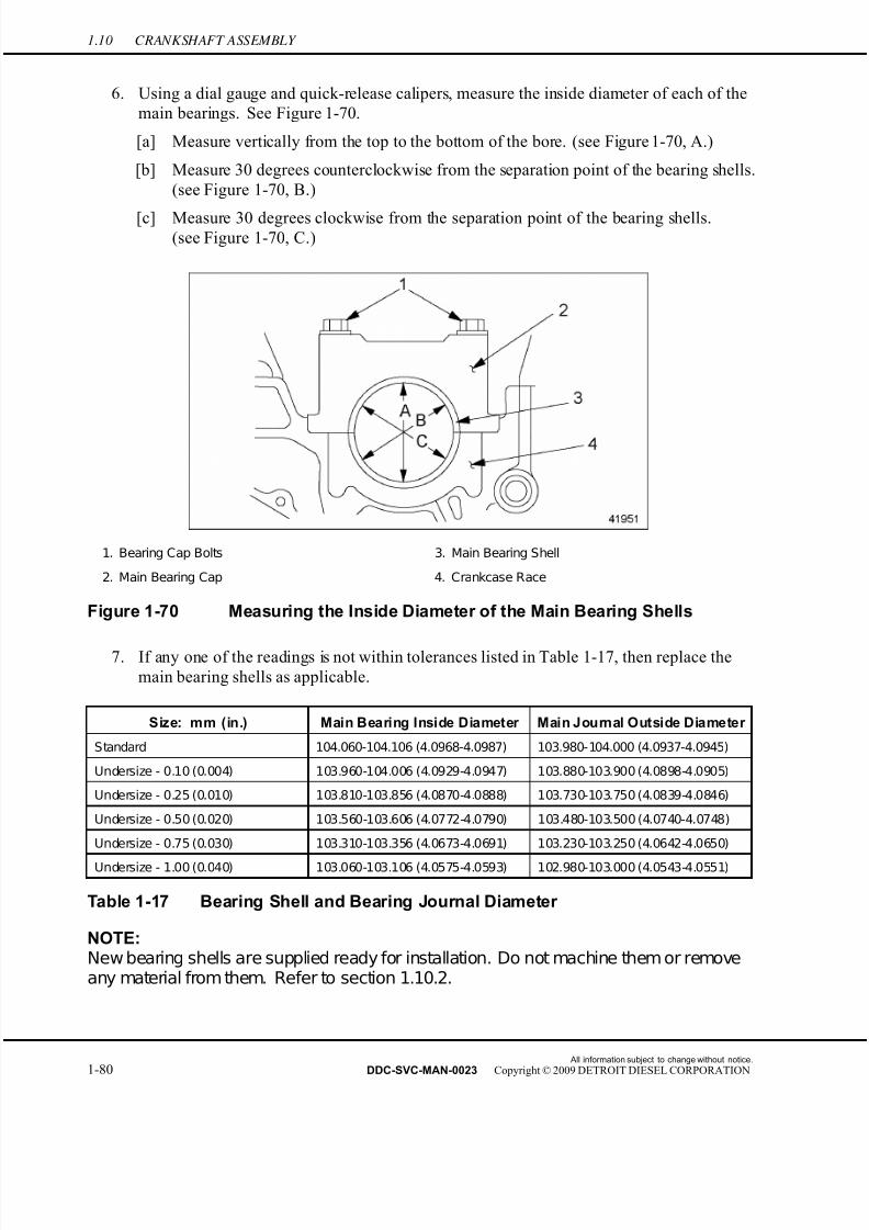
7/22/2019 Manual Mbe 4000 Taller
http://slidepdf.com/reader/full/manual-mbe-4000-taller 124/630
1.10 CRANKSHAFT ASSEMBLY
6. Using a dial gauge and quick-release calipers, measure the inside diameter of each of the
main bearings. See Figure 1-70.
[a] Measure vertically from the top to the bottom of the bore. (see Figure 1-70, A.)
[b] Measure 30 degrees counterclockwise from the separation point of the bearing shells.
(see Figure 1-70, B.)
[c] Measure 30 degrees clockwise from the separation point of the bearing shells.(see Figure 1-70, C.)
1. Bearing Cap Bolts 3. Main Bearing Shell
2. Main Bearing Cap 4. Crankcase Race
Figure 1-70 Measuring the Inside Diameter of the Main Bearing Shells
7. If any one of the readings is not within tolerances listed in Table 1-17, then replace the
main bearing shells as applicable.
Size: mm (in.) Main Bearing Inside Diameter Main Journal Outside Diameter
Standard 104.060-104.106 (4.0968-4.0987) 103.980-104.000 (4.0937-4.0945)
Undersize - 0.10 (0.004) 103.960-104.006 (4.0929-4.0947) 103.880-103.900 (4.0898-4.0905)
Undersize - 0.25 (0.010) 103.810-103.856 (4.0870-4.0888) 103.730-103.750 (4.0839-4.0846)
Undersize - 0.50 (0.020) 103.560-103.606 (4.0772-4.0790) 103.480-103.500 (4.0740-4.0748)
Undersize - 0.75 (0.030) 103.310-103.356 (4.0673-4.0691) 103.230-103.250 (4.0642-4.0650)
Undersize - 1.00 (0.040) 103.060-103.106 (4.0575-4.0593) 102.980-103.000 (4.0543-4.0551)
Table 1-17 Bearing Shell and Bearing Journal Diameter
NOTE:New bearing shells are supplied ready for installation. Do not machine them or removeany material from them. Refer to section 1.10.2.
All information subject to change without notice.
1-80 DDC-SVC-MAN-0023 Copyright © 2009 DETROIT DIESEL CORPORATION
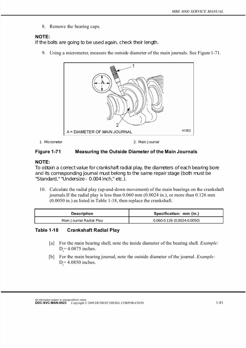
7/22/2019 Manual Mbe 4000 Taller
http://slidepdf.com/reader/full/manual-mbe-4000-taller 125/630
7/22/2019 Manual Mbe 4000 Taller
http://slidepdf.com/reader/full/manual-mbe-4000-taller 126/630
1.10 CRANKSHAFT ASSEMBLY
[c] From the value for the bearing shell diameter, subtract the value for the journal
diameter. This result is the radial play. Example: Ds — D
j= 0.0025 inch.
NOTE:In the above example, both measurements belonged to repair stage "Undersize - 0.010inch." Listed in Table 1-17 is the correct repair stage for each measurement.
11. Install the crankshaft into the crankcase. Refer to section 1.10.2.
FALLING ENGINE
To avoid injury from a falling engine, an adequate liftingdevice with a spreader bar and sling should be used to liftthe engine. The sling and spreader bar should be adjustedso the lifting hooks are vertical to prevent bending the lifter
brackets. To ensure proper weight distribution, all providedlifter brackets must be used.
NOTICE:
A spreader bar must be used at all times in conjunction with thefront and rear lifter brackets to liftthe EGR engine to ensure thatno engine damage will result. The brackets are designed to liftvertically.
12. Install the engine in the vehicle.
1.10.1.3 Crankshaft End Play Checking
Check the crankshaft end play as follows:
1. Remove the crankshaft. Refer to section 1.10.1.
All information subject to change without notice.
1-82 DDC-SVC-MAN-0023 Copyright © 2009 DETROIT DIESEL CORPORATION

7/22/2019 Manual Mbe 4000 Taller
http://slidepdf.com/reader/full/manual-mbe-4000-taller 127/630
MBE 4000 SERVICE MANUAL
2. Check the width of the center main bearing journal. If damage or cracks are present,
replace the crankshaft. See Figure 1-72.
Figure 1-72 Measuring the Width of the Center Journal
3. Check the width of the center main bearing shell. If damage or cracks are present, replace
the crankshaft. See Figure 1-73.
Figure 1-73 Measuring the Width of the Center Main Bearing Shell
NOTE:
To obtain a correct value for crankshaft end play, the width of each bearing shell and itscorresponding journal must belong to the same repair stage (both must be "Standard,""Undersize - 0.020 inch," etc.).
All information subject to change without notice.
DDC-SVC-MAN-0023 Copyright © 2009 DETROIT DIESEL CORPORATION 1-83

7/22/2019 Manual Mbe 4000 Taller
http://slidepdf.com/reader/full/manual-mbe-4000-taller 128/630
1.10 CRANKSHAFT ASSEMBLY
4. Calculate the end play, or axial play, (fore-to-aft movement) of the crankshaft. If the
end play is less than 0.190 mm (0.0074 in.), or more than 0.322 mm (0.0127 in.) as
listed in Table 1-19, then replace the crankshaft.
Description Specification: mm (in.)
End Play (Axial Play) Measured at Center
Bearing J ournal 0.190-0.322 (0.0074-0.0127)
Table 1-19 Crankshaft End Play
[a] For the center main bearing journal, note the width (thickness) of the bearing journal.
Example:Wm
= 1.8120 inches.
[b] For the center main bearing shell, note the width (thickness) of the bearing shell.
Example: Ws
=1.8030 inches.
[c] From the value for the journal width, subtract the value for the bearing shell width.
This result is the end play. Example: Wm — W
s= 0.0090 inch.
NOTE:In the above example, both measurements belonged to repair stage "Standard." If necessary, listed in Table 1-20 are the correct repair stages for each measurement.
Size: mm (in.) Center Bearing Shell Width:
mm (in.)
Center Bearing Journal
Width: mm (in.)
Standard 45.74-45.81 (1.801-1.804) 46.000-46.062 (1.8110-1.8135)
Undersize - 0.020 (0.50) 46.24-46.31 (1.820-1.823) 46.500-46.562 (1.8307-1.8331)
Undersize - 1.00 (0.040) 46.74-46.81 (1.840-1.843) 47.000-47.062 (1.8504-1.8528)
Table 1-20 Bearing Shell and Bear ing Journal Width
5. Install the crankshaft. Refer to section 1.10.2.
All information subject to change without notice.
1-84 DDC-SVC-MAN-0023 Copyright © 2009 DETROIT DIESEL CORPORATION

7/22/2019 Manual Mbe 4000 Taller
http://slidepdf.com/reader/full/manual-mbe-4000-taller 129/630
MBE 4000 SERVICE MANUAL
6. Using a dial gauge and holder, measure the end play of the crankshaft. Measure at the
front end of the crankshaft, with the crankshaft fully installed and all the bearing caps
tightened to the correct torque. See Figure 1-74.
1. Dial Gauge 3. Crankshaft
2. Dial Gauge Holder 4. Screwdriver
Figure 1-74 Measuring the End Play of the Crankshaft
[a] Set up a dial gauge and a dial gauge holder on the front end of the crankshaft. Set the
dial gauge to 5 mm (0.2 in.) preload.
[b] Move the crankshaft all the way forward by prying on one of the bearing caps, then
reset the dial gauge to "0" (zero).
[c] Move the crankshaft all the way aft. Note the end play on the dial gauge.
[d] If the end play does not correspond to the calculated amount (in the example above:
0.0090 in.), replace the crankshaft.
All information subject to change without notice.
DDC-SVC-MAN-0023 Copyright © 2009 DETROIT DIESEL CORPORATION 1-85

7/22/2019 Manual Mbe 4000 Taller
http://slidepdf.com/reader/full/manual-mbe-4000-taller 130/630
1.10 CRANKSHAFT ASSEMBLY
FALLING ENGINE
To avoid injury from a falling engine, an adequate liftingdevice with a spreader bar and sling should be used to lift
the engine. The sling and spreader bar should be adjustedso the lifting hooks are vertical to prevent bending the lifter brackets. To ensure proper weight distribution, all providedlifter brackets must be used.
NOTICE:
A spreader bar must be used at all times in conjunction with thefront and rear lifter brackets to liftthe EGR engine to ensure thatno engine damage will result. The brackets are designed to liftvertically.
7. Install the engine in the vehicle.
1.10.2 Crankshaft Installation
Install the crankshaft as follows:
1. Clean the crankshaft oil passages with a wire brush and blow compressed air through the
passages. Clean the crankshaft, bearings, and bearing seats with a chamois.
2. Lubricate the bearing surfaces with a light coating of clean engine oil.
3. Install the upper bearing shells into the block, in the same order as they were removed.Make sure the locking lugs of the bearing shells fit into the slots of the block bores.
Refer to section 1.10.1.2.
NOTE: The center bearing shell halves must be mounted in the center crankcase race andbearing cap (fourth from either end).
4. Install the lower bearing shells into the main bearing caps, in the same order as they
were removed. Make sure the locking lugs are fully seated in the grooves of the bearing
caps. Refer to section 1.10.1.2.
5. Screw a crankshaft and flywheel guide pin into each end of the crankshaft.
All information subject to change without notice.
1-86 DDC-SVC-MAN-0023 Copyright © 2009 DETROIT DIESEL CORPORATION

7/22/2019 Manual Mbe 4000 Taller
http://slidepdf.com/reader/full/manual-mbe-4000-taller 131/630
MBE 4000 SERVICE MANUAL
FALLING COMPONENT
To avoid injury from a falling component, ensure a proper lifting device is used.
6. Using a suitable hoist, lower the crankshaft into the block.
7. As you set the crankshaft into the block, use the guide pins to maneuver the crankshaft into
position to align the crankshaft gear with the camshaft gear. Fit the marked gear tooth on
the crankshaft gear between the two marked teeth on the camshaft gear. See Figure 1-59.
8. Install all the main bearing caps (including the center bearing cap), with their bearing
shells, on the crankcase journals, as removed. See Figure 1-60.
NOTE:Make sure the numbers on the bearing caps are in ascending order, starting from the
front of the engine.
9. Measure the shaft length of the main bearing-cap bolts. Replace any bolts that exceed the
maximum shaft length of 156.0 mm (6.14 in.). See Figure 1-75.
1. Main Bearing-Cap Bolt
Figure 1-75 Measuring a Main Bearing-Cap Bolt
All information subject to change without notice.
DDC-SVC-MAN-0023 Copyright © 2009 DETROIT DIESEL CORPORATION 1-87

7/22/2019 Manual Mbe 4000 Taller
http://slidepdf.com/reader/full/manual-mbe-4000-taller 132/630
1.10 CRANKSHAFT ASSEMBLY
10. Lubricate the main bearing-cap bolts with a light coating of clean engine oil. Install all the
M18 x 2 main bearing-cap bolts, in the correct order, as removed. Tighten each one in
four stages, listed in Table 1-21, stage by stage.
Max. Shaft Length: mm (in.) Tightening Stage Torque Value: N·m (lb·ft)
Stage 1 100 (74)
Stage 2 200 (148)
Stage 3 300-330 (221-243)156.0 (6.14)
Stage 4 90 degrees
Table 1-21 Tightening Stages, Main Bearing-Cap Bolts
11. Measure the crankshaft end play (fore-to-aft motion) at the center bearing journal.
Refer to section 1.10.1.1.
12. Install the pistons. Refer to section 1.18.2.
13. Install the oil pump and oil pan.
14. Install the flywheel and flywheel housing. Refer to section 1.13.2.
15. Install the front cover housing. Refer to section 1.11.2.
16. Install the cylinder heads. Refer to section 1.2.2.
FALLING ENGINE
To avoid injury from a falling engine, an adequate lifting
device with a spreader bar and sling should be used to liftthe engine. The sling and spreader bar should be adjustedso the lifting hooks are vertical to prevent bending the lifter brackets. To ensure proper weight distribution, all providedlifter brackets must be used.
NOTICE:
A spreader bar must be used at all times in conjunction with thefront and rear lifter brackets to liftthe EGR engine to ensure thatno engine damage will result. The brackets are designed to lift
vertically.
17. Remove the engine from the stand.
18. Install the engine in the vehicle.
All information subject to change without notice.
1-88 DDC-SVC-MAN-0023 Copyright © 2009 DETROIT DIESEL CORPORATION

7/22/2019 Manual Mbe 4000 Taller
http://slidepdf.com/reader/full/manual-mbe-4000-taller 133/630
MBE 4000 SERVICE MANUAL
1.10.3 Crankshaft Gear Replacement
Replace the crankshaft gear as follows:
1. Remove the transmission and clutch. Refer to the appropriate vehicle service manual.
2. Remove the oil pan and gasket.
3. Support the engine by placing suitable jack stands under the cylinder block pan rails.Make sure not to damage the sealing surfaces of the pan rails.
4. Remove the rear engine mounts from the flywheel housing. Refer to the applicable
vehicle service manual.
5. Remove the flywheel housing. Refer to section 1.17.1.
1. Camshaft Gear 2. Crank haft Gear 3. Dowel Pin
Figure 1-76 Aligning the Marked Gear Teeth
6. Rotate the crankshaft until the marked gear tooth on the crankshaft gear is aligned between
the two similarly marked teeth on the camshaft gear. See Figure 1-76.
All information subject to change without notice.
DDC-SVC-MAN-0023 Copyright © 2009 DETROIT DIESEL CORPORATION 1-89
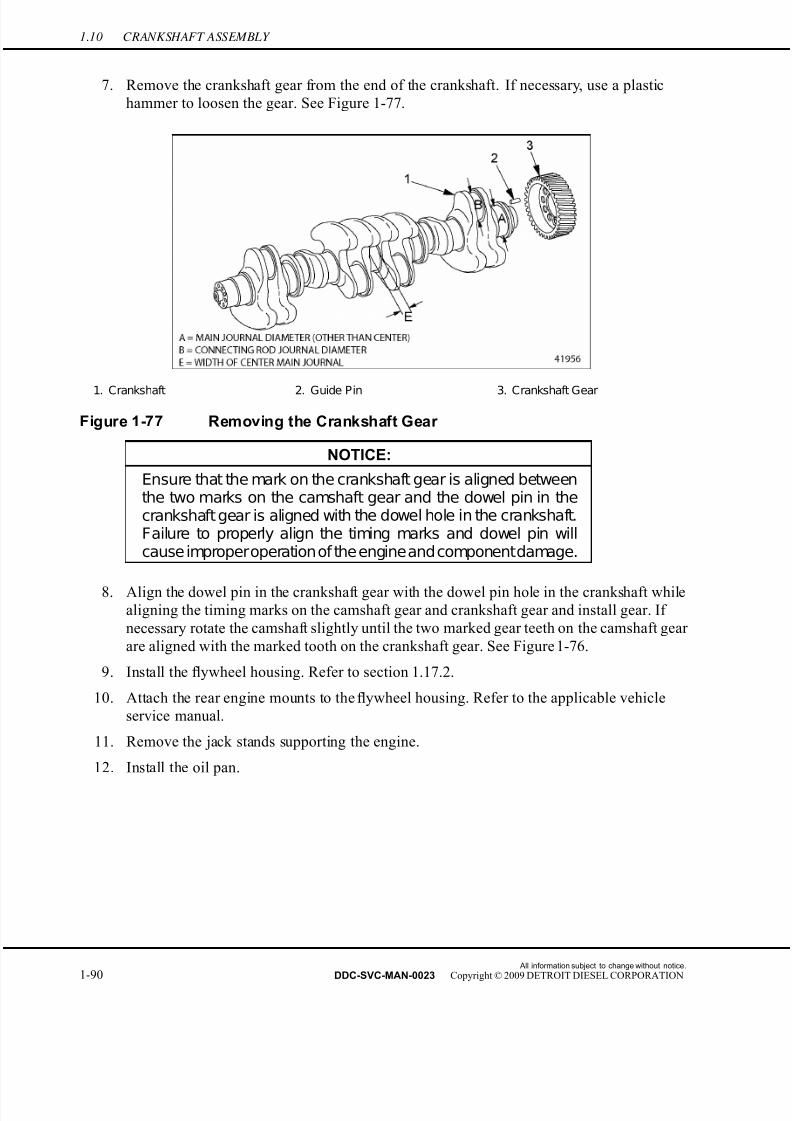
7/22/2019 Manual Mbe 4000 Taller
http://slidepdf.com/reader/full/manual-mbe-4000-taller 134/630
1.10 CRANKSHAFT ASSEMBLY
7. Remove the crankshaft gear from the end of the crankshaft. If necessary, use a plastic
hammer to loosen the gear. See Figure 1-77.
1. Crankshaft 2. Guide Pin 3. Crankshaft Gear
Figure 1-77 Removing the Crankshaft Gear
NOTICE:
Ensure that the mark on the crankshaft gear is aligned betweenthe two marks on the camshaft gear and the dowel pin in thecrankshaft gear is aligned with the dowel hole in the crankshaft.Failure to properly align the timing marks and dowel pin willcause improperoperationof the engineandcomponentdamage.
8. Align the dowel pin in the crankshaft gear with the dowel pin hole in the crankshaft whilealigning the timing marks on the camshaft gear and crankshaft gear and install gear. If
necessary rotate the camshaft slightly until the two marked gear teeth on the camshaft gear
are aligned with the marked tooth on the crankshaft gear. See Figure 1-76.
9. Install the flywheel housing. Refer to section 1.17.2.
10. Attach the rear engine mounts to the flywheel housing. Refer to the applicable vehicle
service manual.
11. Remove the jack stands supporting the engine.
12. Install the oil pan.
All information subject to change without notice.
1-90 DDC-SVC-MAN-0023 Copyright © 2009 DETROIT DIESEL CORPORATION
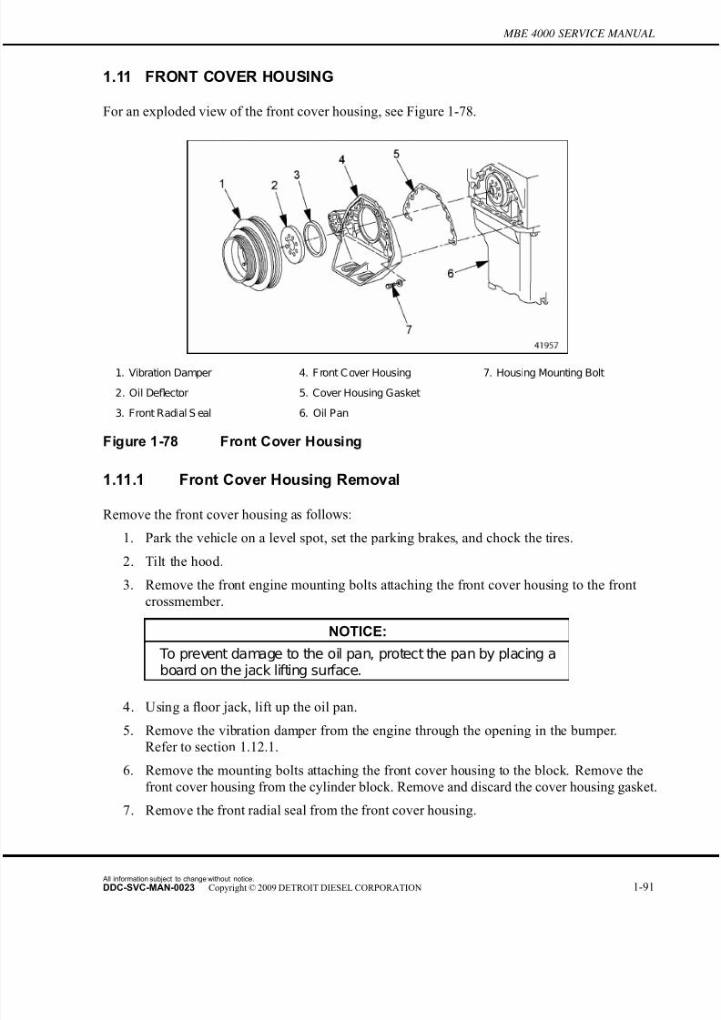
7/22/2019 Manual Mbe 4000 Taller
http://slidepdf.com/reader/full/manual-mbe-4000-taller 135/630
MBE 4000 SERVICE MANUAL
1.11 FRONT COVER HOUSING
For an exploded view of the front cover housing, see Figure 1-78.
1. Vibration Damper 4. F ront C over Housing 7. Housing Mounting Bolt
2. Oil Deflector 5. Cover Housing Gasket
3. Front Radial S eal 6. Oil Pan
Figure 1-78 Front Cover Housing
1.11.1 Front Cover Housing Removal
Remove the front cover housing as follows:
1. Park the vehicle on a level spot, set the parking brakes, and chock the tires.
2. Tilt the hood.
3. Remove the front engine mounting bolts attaching the front cover housing to the front
crossmember.
NOTICE:
To prevent damage to the oil pan, protect the pan by placing aboard on the jack lifting surface.
4. Using a floor jack, lift up the oil pan.
5. Remove the vibration damper from the engine through the opening in the bumper.
Refer to section 1.12.1.
6. Remove the mounting bolts attaching the front cover housing to the block. Remove the
front cover housing from the cylinder block. Remove and discard the cover housing gasket.
7. Remove the front radial seal from the front cover housing.
All information subject to change without notice.
DDC-SVC-MAN-0023 Copyright © 2009 DETROIT DIESEL CORPORATION 1-91
7/22/2019 Manual Mbe 4000 Taller
http://slidepdf.com/reader/full/manual-mbe-4000-taller 136/630
1.11 FRONT COVER HOUSING
1.11.2 Front Cover Housing Installation
Install the front cover housing as follows:
1. Install a new gasket on the cylinder block.
2. Lubricate the seal race on the crankshaft with a light coating of engine oil.
3. Install the front cover on the cylinder block. Tighten the front cover mounting bolts to60 N·m (44 lb·ft).
4. Install the front radial seal. Refer to section 1.7.2.
5. Install the vibration damper on the crankshaft. Refer to section 1.12.2.
6. Lower the oil pan and remove the floor jack.
7. Install the front engine mounting bolts attaching the front cover housing to the front
crossmember. Tighten the front engine mounting bolts to 325 N·m (240 lb·ft).
8. Close the hood, and remove the chocks from the tires.
All information subject to change without notice.
1-92 DDC-SVC-MAN-0023 Copyright © 2009 DETROIT DIESEL CORPORATION

7/22/2019 Manual Mbe 4000 Taller
http://slidepdf.com/reader/full/manual-mbe-4000-taller 137/630
MBE 4000 SERVICE MANUAL
1.12 CRANKSHAFT VIBRATION DAMPER
A special tool, Engine Barring Tool (J–46392) is required for this procedure.
1.12.1 Crankshaft Vibration Damper Removal
Remove the crankshaft vibration damper as follows:
1. Remove the drive belts from the alternator, coolant-pump, idler, and air-conditioner
compressor pulleys, as installed.
2. Install the engine barring tool (J–46392)with the locking pin in place. Refer to section
1.16.2.
3. To gain access to the vibration damper, remove the lower mounting bolts from the bottom
of the front fairing/bumper.
4. Remove the mounting bolts from the vibration damper. Drop the vibration damper down
below the radiator and remove it from the engine. See Figure 1-79.
1. Vibration Damper 3. Oil Deflector
2. Mounting Bolt 4. End of Crankshaft
Figure 1-79 Vibration Damper Removal
5. Remove the oil deflector from the crankshaft.
6. Inspect the vibration damper for signs of wear, dents, deformation, or other signs of damage. Replace the damper if the belt contact surface is worn or damaged.
NOTE: The vibration damper has a crankshaft pulley bolted to it to accommodate two additionaldrive belts. It is not necessary to disassemble the vibration damper unless the crankshaftpulley is damaged and needs to be replaced.
All information subject to change without notice.
DDC-SVC-MAN-0023 Copyright © 2009 DETROIT DIESEL CORPORATION 1-93

7/22/2019 Manual Mbe 4000 Taller
http://slidepdf.com/reader/full/manual-mbe-4000-taller 138/630
1.12 CRANKSHAFT VIBRATION DAMPER
1.12.2 Crankshaft Vibration Damper Installation
Install the crankshaft vibration damper as follows:
NOTE:Check the crankshaft front seal for oil leaks. If leakage is found, replace the front seal.
Refer to section 1.7.
1. Install the oil deflector. Make sure the rim is facing the engine.
2. Install the vibration damper on the crankshaft, as removed. Tighten the bolts 200 N·m
(148 lb·ft). Use an alternating sequence until all six bolts are tight.
3. Install the lower mounting bolts on the bottom of the front fairing/bumper, as removed.
4. Remove the engine barring tool from the flywheel housing. Refer to section 1.16.2.
5. Install the drive belts on their pulleys, as removed.
All information subject to change without notice.
1-94 DDC-SVC-MAN-0023 Copyright © 2009 DETROIT DIESEL CORPORATION
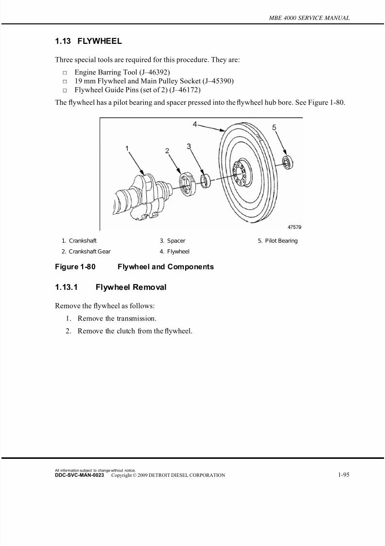
7/22/2019 Manual Mbe 4000 Taller
http://slidepdf.com/reader/full/manual-mbe-4000-taller 139/630
MBE 4000 SERVICE MANUAL
1.13 FLYWHEEL
Three special tools are required for this procedure. They are:
□ Engine Barring Tool (J–46392)
□ 19 mm Flywheel and Main Pulley Socket (J–45390)
□ Flywheel Guide Pins (set of 2) (J–46172)
The flywheel has a pilot bearing and spacer pressed into the flywheel hub bore. See Figure 1-80.
1. Crankshaft 3. Spacer 5. Pilot Bearing
2. Crankshaft Gear 4. Flywheel
Figure 1-80 Flywheel and Components
1.13.1 Flywheel Removal
Remove the flywheel as follows:
1. Remove the transmission.
2. Remove the clutch from the flywheel.
All information subject to change without notice.
DDC-SVC-MAN-0023 Copyright © 2009 DETROIT DIESEL CORPORATION 1-95
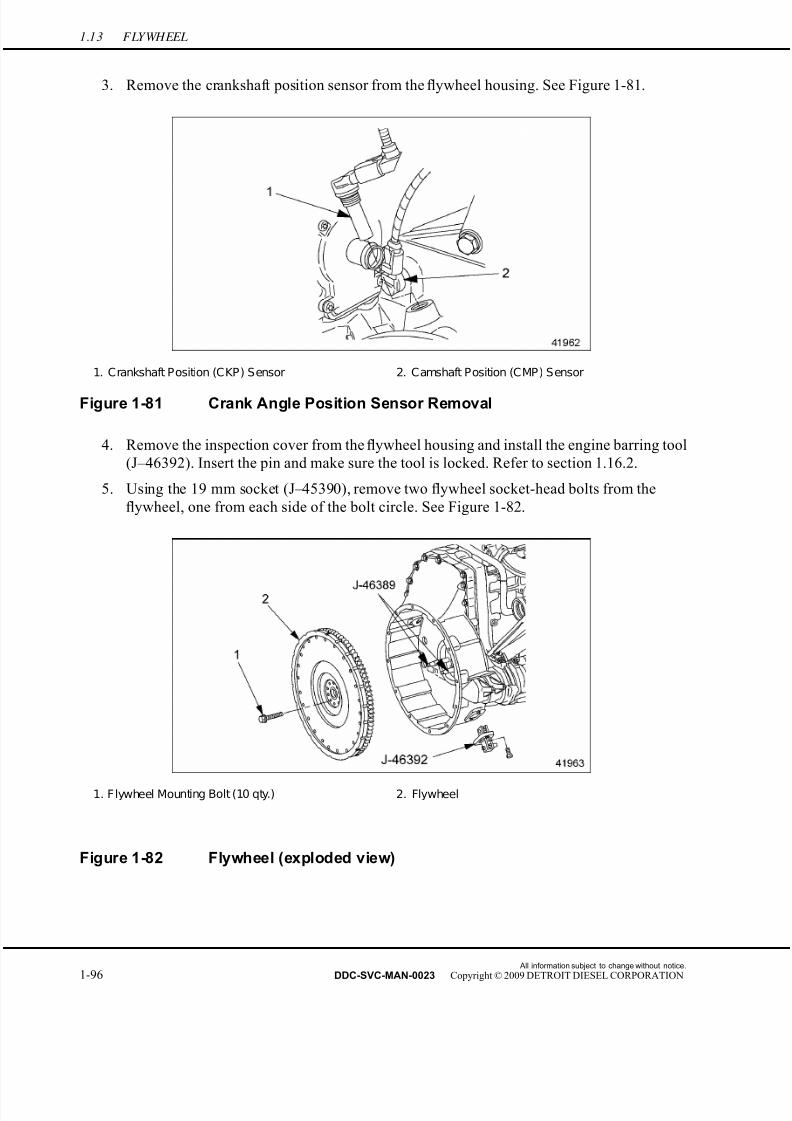
7/22/2019 Manual Mbe 4000 Taller
http://slidepdf.com/reader/full/manual-mbe-4000-taller 140/630
1.13 FLYWHEEL
3. Remove the crankshaft position sensor from the flywheel housing. See Figure 1-81.
1. Crankshaft Position (CKP) Sensor 2. Camshaft Position (CMP) Sensor
Figure 1-81 Crank Angle Position Sensor Removal
4. Remove the inspection cover from the flywheel housing and install the engine barring tool
(J–46392). Insert the pin and make sure the tool is locked. Refer to section 1.16.2.
5. Using the 19 mm socket (J–45390), remove two flywheel socket-head bolts from the
flywheel, one from each side of the bolt circle. See Figure 1-82.
1. Flywheel Mounting Bolt (10 qty.) 2. Flywheel
Figure 1-82 Flywheel (exploded view)
All information subject to change without notice.
1-96 DDC-SVC-MAN-0023 Copyright © 2009 DETROIT DIESEL CORPORATION

7/22/2019 Manual Mbe 4000 Taller
http://slidepdf.com/reader/full/manual-mbe-4000-taller 141/630
MBE 4000 SERVICE MANUAL
6. Screw the two flywheel guide pins (J-46172) into the empty bolt holes in the center of
the flywheel. See Figure 1-83.
1. Bolt used as a handle 2. Flywheel Mounting Bolt
Figure 1-83 Flywheel Removal
FALLING FLYWHEEL
To avoid injury from a falling flywheel when removing thelast bolt, hold the flywheel against the crankshaft by handto prevent it from slipping off the crankshaft. The flywheel
is not doweled to the crankshaft.
7. Remove the remaining eight flywheel bolts.
8. Remove the engine barring tool (J–46392). Refer to section 1.16.2.
FALLING COMPONENT
To avoid injury from a falling component, ensure a proper lifting device is used.
9. Remove the flywheel, leaving the guide pins (J–46172) in place. See Figure 1-83.
[a] On opposite sides of the bolt circle, screw a bolt into each of two threaded clutch
bolt holes.
[b] Using the two bolts as handles, dislodge the flywheel from the crankshaft flange
and remove it from the flywheel housing.
All information subject to change without notice.
DDC-SVC-MAN-0023 Copyright © 2009 DETROIT DIESEL CORPORATION 1-97
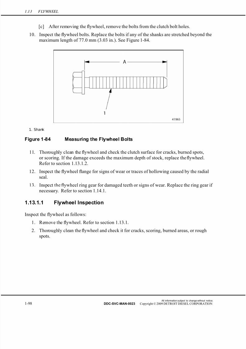
7/22/2019 Manual Mbe 4000 Taller
http://slidepdf.com/reader/full/manual-mbe-4000-taller 142/630
1.13 FLYWHEEL
[c] After removing the flywheel, remove the bolts from the clutch bolt holes.
10. Inspect the flywheel bolts. Replace the bolts if any of the shanks are stretched bey ond the
maximum length of 77.0 mm (3.03 in.). See Figure 1-84.
1. Shank
Figure 1-84 Measuring the Flywheel Bolts
11. Thoroughly clean the flywheel and check the clutch surface for cracks, burned spots,
or scoring. If the damage exceeds the maximum depth of stock, replace the flywheel.
Refer to section 1.13.1.2.
12. Inspect the flywheel flange for signs of wear or traces of hollowing caused by the radial
seal.
13. Inspect the flywheel ring gear for damaged teeth or signs of wear. Replace the ring gear if necessary. Refer to section 1.14.1.
1.13.1.1 Flywheel Inspection
Inspect the flywheel as follows:
1. Remove the flywheel. Refer to section 1.13.1.
2. Thoroughly clean the flywheel and check it for cracks, scoring, burned areas, or rough
spots.
All information subject to change without notice.
1-98 DDC-SVC-MAN-0023 Copyright © 2009 DETROIT DIESEL CORPORATION

7/22/2019 Manual Mbe 4000 Taller
http://slidepdf.com/reader/full/manual-mbe-4000-taller 143/630
MBE 4000 SERVICE MANUAL
3. Using an accurate straightedge and a feeler gauge, check the friction (clutch) surface for
evenness. See Figure 1-85. If the surface has areas that are too high or too low, replace
the flywheel.
1. Straightedge 2. Friction Surface
Figure 1-85 Checking the Friction Surface for Evenness
4. Check the bearing surface and the threaded holes for wear and damage.
1.13.1.2 Flywheel Machining
Machine the flywheel as follows:
NOTE:Before beginning any machining work on the flywheel, check it to see if machining ispossible. If the scores or cracks are deeper than 1 mm (0.04 in.), replace theflywheel. If the width of the flywheel between the friction surface and the mounting flange is lessthan 60 mm (2.4 in.), replace the flywheel.
PERSONAL INJURY
To avoid injury while performing the test or procedure, wear
adequate eye, face protection, and heat-resistant gloves.
1. Machine the flywheel friction surface, if required, to the specifications listed in Table
1-22. See Figur e 1-86. The surface finish (peak-to-valley height) after machining should
be 0.016 mm (0.0006 in.). A rougher surface finish will cause rapid clutch lining wear,
while a smoother finish could cause dif ficulties in clutch disengagement. See Figure 1-87
for the locations on the flywheel to coordinate with the specifications in the table.
All information subject to change without notice.
DDC-SVC-MAN-0023 Copyright © 2009 DETROIT DIESEL CORPORATION 1-99

7/22/2019 Manual Mbe 4000 Taller
http://slidepdf.com/reader/full/manual-mbe-4000-taller 144/630
1.13 FLYWHEEL
Figure 1-86 Machining the Flywheel Friction Surface
Description Specification: mm (in.)
Flywheel Outside Diameter 486.60-487.40 (19.157-19.189)
Flywheel Shoulder Diameter (for ring gear mounting) 432.450-432.645 (17.0256-17.0332)
Flywheel Diameter at Crankshaft Flange 114.980-115.015 (4.5268-4.5281)
Flywheel Diameter for Mounting Clutch 475.000-475.063 (18.7008-18.7032)
Flywheel Minimum Width Between Friction Surface
and Mounting Flange After Machining60 (2.4)
Flywheel Maximum Overall Width 70 (2.8)
Peak-to-Valley Height (Rz) of Clutch F riction S urface 0.016 (0.0006)
Flywheel Permissible Deviation From True
(radial and lateral)0.2 (0.008)
Table 1-22 Flywheel Specifications
All information subject to change without notice.
1-100 DDC-SVC-MAN-0023 Copyright © 2009 DETROIT DIESEL CORPORATION
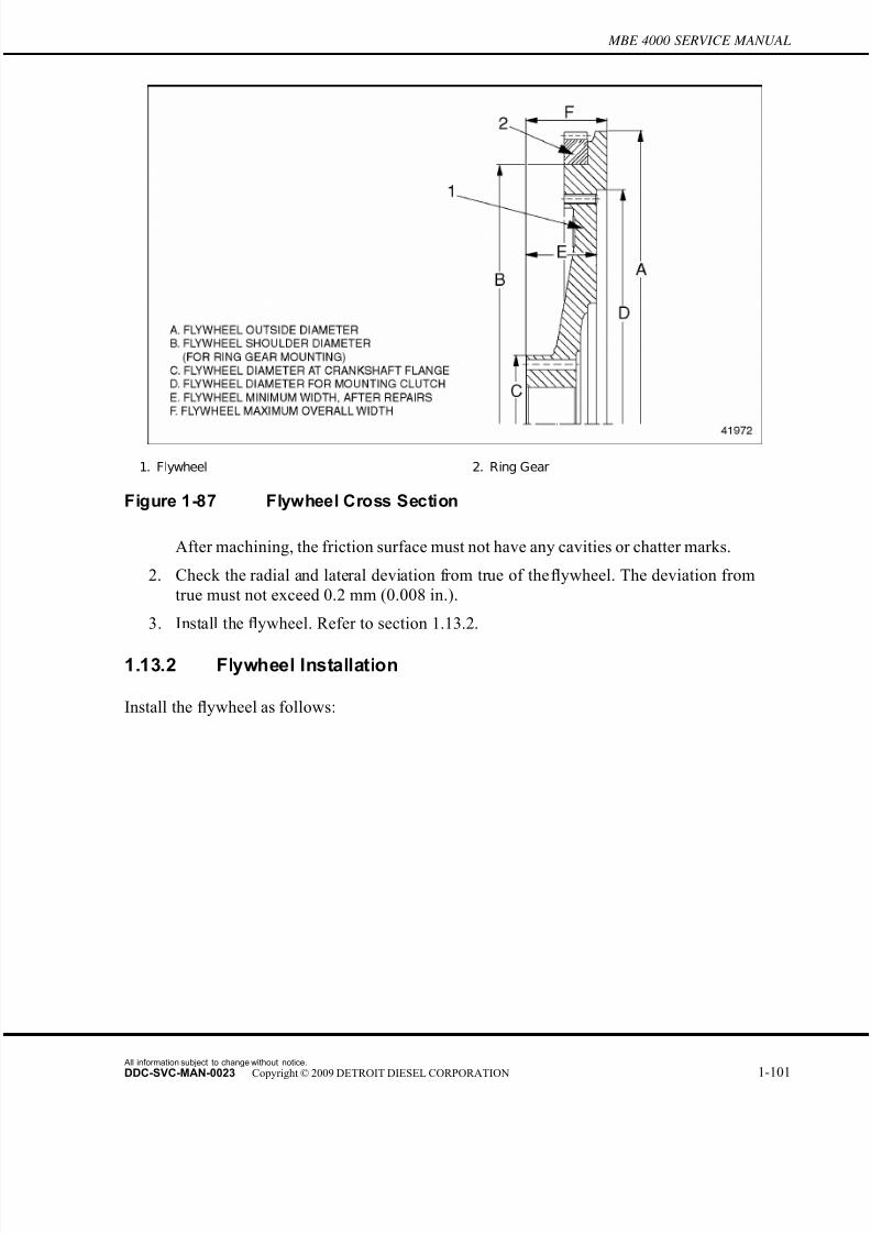
7/22/2019 Manual Mbe 4000 Taller
http://slidepdf.com/reader/full/manual-mbe-4000-taller 145/630
MBE 4000 SERVICE MANUAL
1. Flywheel 2. Ring Gear
Figure 1-87 Flywheel Cross Section
After machining, the friction surface must not have any cavities or chatter marks.
2. Check the radial and lateral deviation from true of the flywheel. The deviation from
true must not exceed 0.2 mm (0.008 in.).
3. Install the flywheel. Refer to section 1.13.2.
1.13.2 Flywheel Installation
Install the flywheel as follows:
All information subject to change without notice.
DDC-SVC-MAN-0023 Copyright © 2009 DETROIT DIESEL CORPORATION 1-101

7/22/2019 Manual Mbe 4000 Taller
http://slidepdf.com/reader/full/manual-mbe-4000-taller 146/630
1.13 FLYWHEEL
NOTICE:
Ensure that the spacer ring is installed in the flywheel to priorto installing the flywheel on the crankshaft. Failure to install thespacer ring will result in improper operation of the transmission.
FALLING COMPONENT
To avoid injury from a falling component ensure, a proper lifting device is used.
1. Ensure that the spacer ring is installed in the flywheel to prior to installing the flywheel
on the crankshaft.
1. Pilot Bearing 2. Spacer Ring 3. Flywheel
Figure 1-88 Pilot Bearing and Spacer Ring
2. Using a suitable lifting device install the flywheel over the guide pins (J–46172). Align
the dowel on the crankshaft with the guide hole in the flywheel (arrow). See Figure 1-89.
All information subject to change without notice.
1-102 DDC-SVC-MAN-0023 Copyright © 2009 DETROIT DIESEL CORPORATION
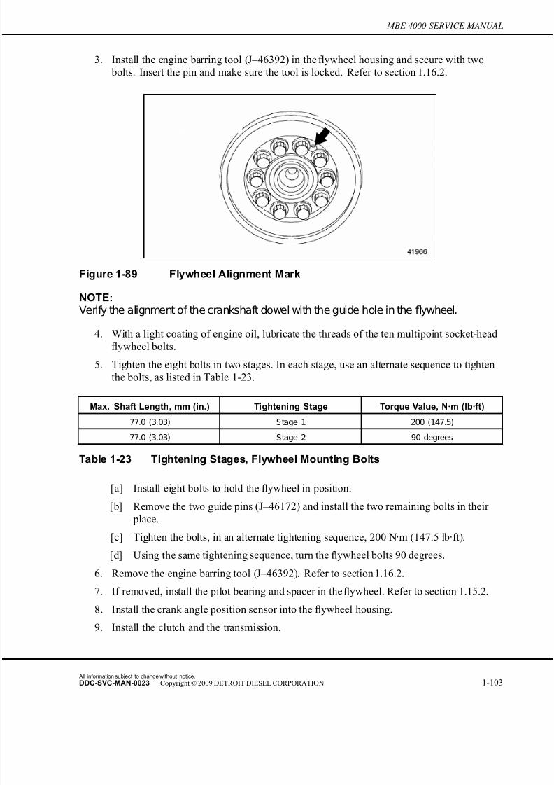
7/22/2019 Manual Mbe 4000 Taller
http://slidepdf.com/reader/full/manual-mbe-4000-taller 147/630
MBE 4000 SERVICE MANUAL
3. Install the engine barring tool (J–46392) in the flywheel housing and secure with two
bolts. Insert the pin and make sure the tool is locked. Refer to section 1.16.2.
Figure 1-89 Flywheel Alignment Mark
NOTE:Verify the alignment of the crankshaft dowel with the guide hole in the flywheel.
4. With a light coating of engine oil, lubricate the threads of the ten multipoint socket-head
flywheel bolts.
5. Tighten the eight bolts in two stages. In each stage, use an alternate sequence to tighten
the bolts, as listed in Table 1-23.
Max. Shaft Length, mm (in.) Tightening Stage Torque Value, N·m (lb·ft)
77.0 (3.03) Stage 1 200 (147.5)
77.0 (3.03) Stage 2 90 degrees
Table 1-23 Tightening Stages, Flywheel Mounting Bolts
[a] Install eight bolts to hold the flywheel in position.
[b] Remove the two guide pins (J–46172) and install the two remaining bolts in their
place.
[c] Tighten the bolts, in an alternate tightening sequence, 200 N·m (147.5 lb·ft).
[d] Using the same tightening sequence, turn the flywheel bolts 90 degrees.
6. Remove the engine barring tool (J–46392). Refer to section 1.16.2.
7. If removed, install the pilot bearing and spacer in the flywheel. Refer to section 1.15.2.
8. Install the crank angle position sensor into the flywheel housing.
9. Install the clutch and the transmission.
All information subject to change without notice.
DDC-SVC-MAN-0023 Copyright © 2009 DETROIT DIESEL CORPORATION 1-103
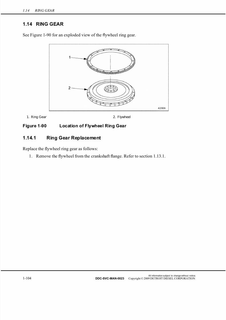
7/22/2019 Manual Mbe 4000 Taller
http://slidepdf.com/reader/full/manual-mbe-4000-taller 148/630
1.14 RING GEAR
1.14 RING GEAR
See Figure 1-90 for an exploded view of the flywheel ring gear.
1. Ring Gear 2. Flywheel
Figure 1-90 Location of Flywheel Ring Gear
1.14.1 Ring Gear Replacement
Replace the flywheel ring gear as follows:
1. Remove the flywheel from the crankshaft flange. Refer to section 1.13.1.
All information subject to change without notice.
1-104 DDC-SVC-MAN-0023 Copyright © 2009 DETROIT DIESEL CORPORATION
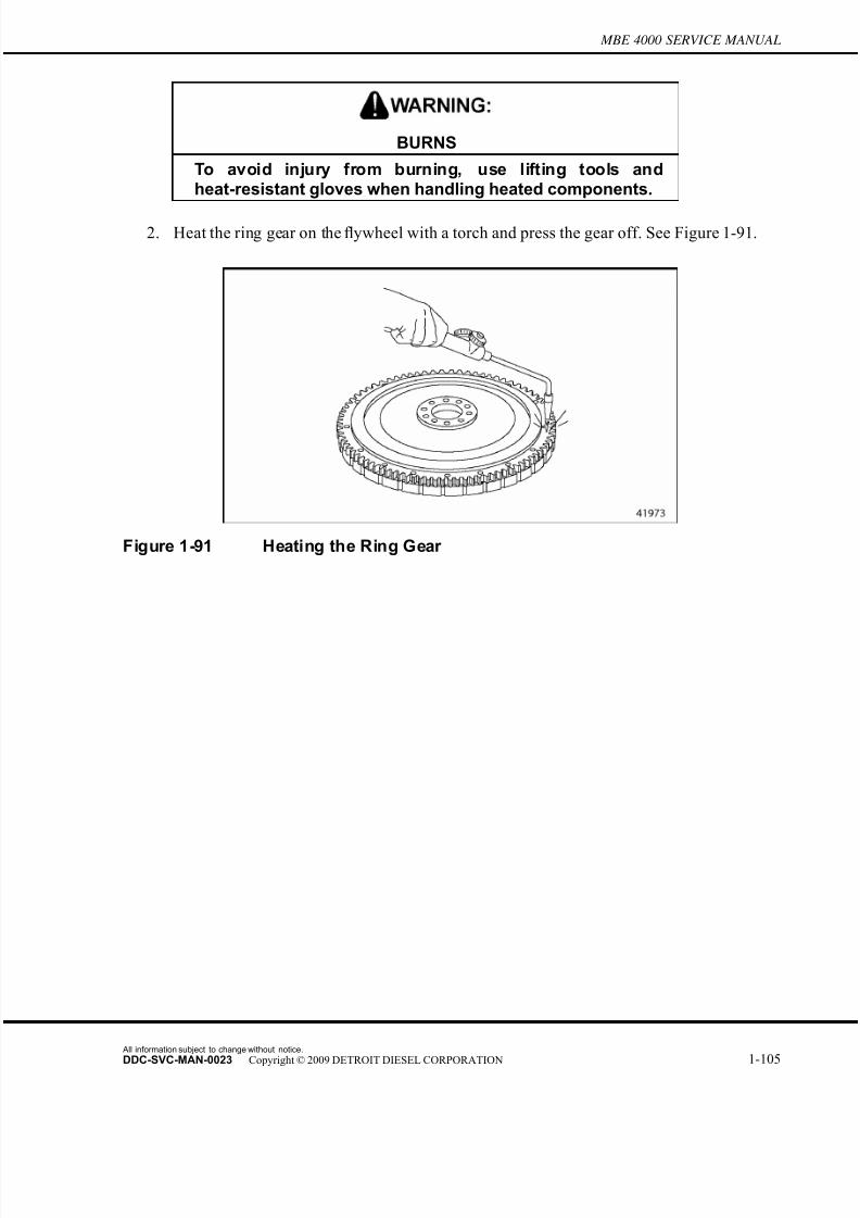
7/22/2019 Manual Mbe 4000 Taller
http://slidepdf.com/reader/full/manual-mbe-4000-taller 149/630
MBE 4000 SERVICE MANUAL
BURNS
To avoid injury from burning, use lifting tools andheat-resistant gloves when handling heated components.
2. Heat the ring gear on the flywheel with a torch and press the gear off. See Figure 1-91.
Figure 1-91 Heating the Ring Gear
All information subject to change without notice.
DDC-SVC-MAN-0023 Copyright © 2009 DETROIT DIESEL CORPORATION 1-105
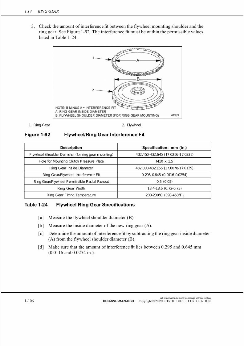
7/22/2019 Manual Mbe 4000 Taller
http://slidepdf.com/reader/full/manual-mbe-4000-taller 150/630
1.14 RING GEAR
3. Check the amount of interference fit between the flywheel mounting shoulder and the
ring gear. See Figure 1-92. The interference fit must be within the permissible values
listed in Table 1-24.
1. Ring Gear 2. Flywheel
Figure 1-92 Flywheel/Ring Gear Interference Fit
Description Specification: mm (in.)
Flywheel Shoulder Diameter (for ring gear mounting) 432.450-432.645 (17.0256-17.0332)
Hole for Mounting Clutch P ressure Plate M10 x 1.5
Ring Gear Inside Diameter 432.000-432.155 (17.0078-17.0139)
Ring Gear/Flywheel Interference Fit 0.295-0.645 (0.0116-0.0254)
R ing Gear/F lywheel P ermissible R adial R unout 0.5 (0.02)
Ring Gear Width 18.4-18.6 (0.72-0.73)
R ing Gear F itting Temperature 200-230°C (390-450°F )
Table 1-24 Flywheel Ring Gear Specifications
[a] Measure the flywheel shoulder diameter (B).
[b] Measure the inside diameter of the new ring gear (A).
[c] Determine the amount of interference fit by subtracting the ring gear inside diameter
(A) from the flywheel shoulder diameter (B).
[d] Make sure that the amount of interference fit lies between 0.295 and 0.645 mm
(0.0116 and 0.0254 in.).
All information subject to change without notice.
1-106 DDC-SVC-MAN-0023 Copyright © 2009 DETROIT DIESEL CORPORATION
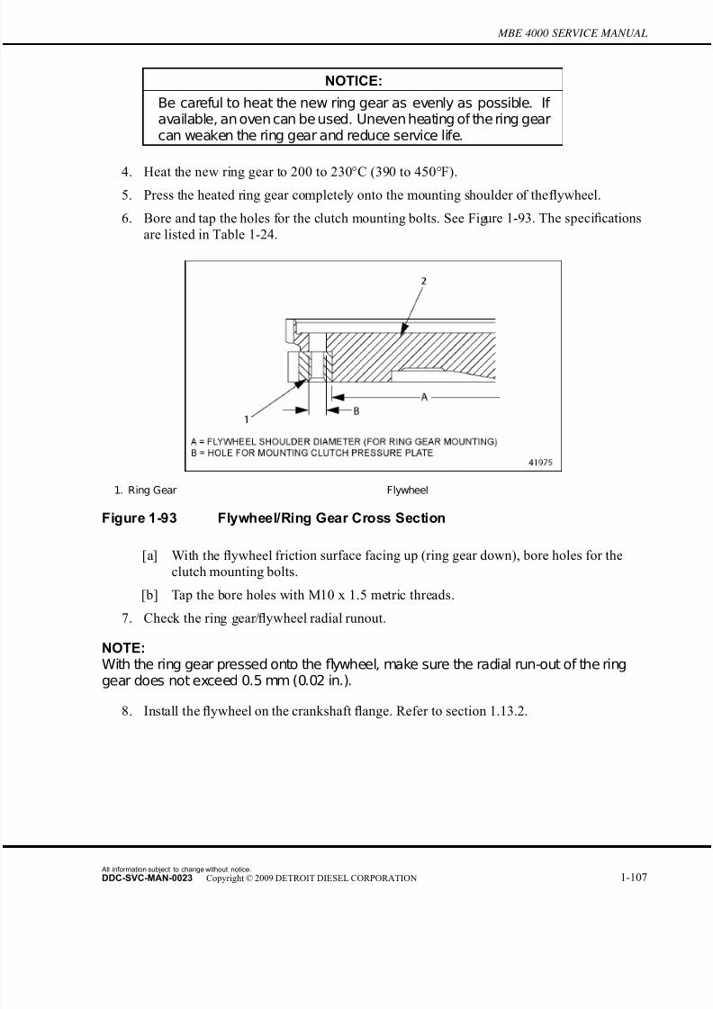
7/22/2019 Manual Mbe 4000 Taller
http://slidepdf.com/reader/full/manual-mbe-4000-taller 151/630
MBE 4000 SERVICE MANUAL
NOTICE:
Be careful to heat the new ring gear as evenly as possible. If available, an oven can be used. Uneven heating of the ring gearcan weaken the ring gear and reduce service life.
4. Heat the new ring gear to 200 to 230°C (390 to 450°F).5. Press the heated ring gear completely onto the mounting shoulder of the flywheel.
6. Bore and tap the holes for the clutch mounting bolts. See Figure 1-93. The specifications
are listed in Table 1-24.
1. Ring Gear Flywheel
Figure 1-93 Flywheel/Ring Gear Cross Section
[a] With the flywheel friction surface facing up (ring gear down), bore holes for the
clutch mounting bolts.
[b] Tap the bore holes with M10 x 1.5 metric threads.
7. Check the ring gear/flywheel radial runout.
NOTE:With the ring gear pressed onto the flywheel, make sure the radial run-out of the ringgear does not exceed 0.5 mm (0.02 in.).
8. Install the flywheel on the crankshaft flange. Refer to section 1.13.2.
All information subject to change without notice.
DDC-SVC-MAN-0023 Copyright © 2009 DETROIT DIESEL CORPORATION 1-107
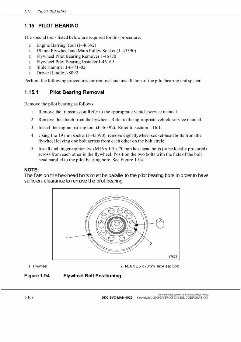
7/22/2019 Manual Mbe 4000 Taller
http://slidepdf.com/reader/full/manual-mbe-4000-taller 152/630
1.15 PILOT BEARING
1.15 PILOT BEARING
The special tools listed below are required for this procedure:
□ Engine Barring Tool (J–46392)
□ 19 mm Flywheel and Main Pulley Socket (J–45390)
□ Flywheel Pilot Bearing Remover J-46170
□ Flywheel Pilot Bearing Installer J-46169
□ Slide Hammer J-6471–02
□ Driver Handle J-8092
Perform the following procedures for removal and installation of the pilot bearing and spacer.
1.15.1 Pilot Bearing Removal
Remove the pilot bearing as follows:
1. Remove the transmission.Refer to the appropriate vehicle service manual.
2. Remove the clutch from the flywheel. Refer to the appropriate vehicle service manual.
3. Install the engine barring tool (J–46392). Refer to section 1.16.1.
4. Using the 19 mm socket (J–45390), remove eight flywheel socket-head bolts from the
flywheel leaving one bolt across from each other on the bolt circle.
5. Install and finger-tighten two M16 x 1.5 x 70 mm hex-head bolts (to be locally procured)
across from each other in the flywheel. Position the two bolts with the flats of the bolt
head parallel to the pilot bearing bore. See Figure 1-94.
NOTE: The flats on the hex-head bolts must be parallel to the pilot bearing bore in order to have
suf ficient clearance to remove the pilot bearing.
1. Flywheel 2. M16 x 1.5 x 70mm Hex-Head Bolt
Figure 1-94 Flywheel Bolt Positioning
All information subject to change without notice.
1-108 DDC-SVC-MAN-0023 Copyright © 2009 DETROIT DIESEL CORPORATION

7/22/2019 Manual Mbe 4000 Taller
http://slidepdf.com/reader/full/manual-mbe-4000-taller 153/630
MBE 4000 SERVICE MANUAL
6. Remove the remaining two flywheel bolts.
7. Inspect the flywheel bolts. Replace the bolts if any of the shanks are stretched bey ond the
maximum length of 77.0 mm (3.03 in.). See Figure 1-95.
1. Shank
Figure 1-95 Measuring the Flywheel Bolts
8. Install pilot bearing remover tool (J-46170) into the bearing and expand the tool to fit
snug in the bearing inside diameter.
9. Attach a suitable slide hammer (J-6471–02), with 5/8–18 male threads, to the extractor
and remove the bearing. See Figure 1-96.
1. Flywheel 2. M16 x 1.5 x 70 mm Bolt
Figure 1-96 Pilot Bearing Removal
All information subject to change without notice.
DDC-SVC-MAN-0023 Copyright © 2009 DETROIT DIESEL CORPORATION 1-109

7/22/2019 Manual Mbe 4000 Taller
http://slidepdf.com/reader/full/manual-mbe-4000-taller 154/630
1.15 PILOT BEARING
10. Clean the pilot bearing bore in the flywheel and inspect for damage or spun bearing,
replace flywheel if damage is found.
1.15.2 Pilot Bearing Installation
Install the pilot bearing as follows:
NOTICE:
Ensure that the spacer ring is installed prior to installing the pilotbearing in theflywheel. Failureto install thespacerringwillresultin improper operation of the transmission.
1. Ensure that the spacer ring is installed in the flywheel prior to installing the pilot bearing.
See Figure 1-97.
2. Using the flywheel pilot bearing installer (J-46169) and driver handle (J-8092), position
the bearing on the flywheel and drive it into the flywheel until seated. See Figure 1-97.
1. Pilot Bearing 3. Flywheel
2. Spacer Ring 4. M16 x 1.5 x 70 mm Hex-Head Bolt
Figure 1-97 Pilot Bearing Installation
3. Lubricate the flywheel bolts with a light coat of engine oil.
4. Install two standard flywheel bolts, finger tight, perpendicular to the M16 x 1.5 x 70mm bolts. Remove the special bolts.
5. Install the remaining eight flywheel bolts.
All information subject to change without notice.
1-110 DDC-SVC-MAN-0023 Copyright © 2009 DETROIT DIESEL CORPORATION
7/22/2019 Manual Mbe 4000 Taller
http://slidepdf.com/reader/full/manual-mbe-4000-taller 155/630
MBE 4000 SERVICE MANUAL
6. Tighten the flywheel bolts in two stages. In each stage, use an alternate sequence to tighten
the bolts, as listed in Table 1-25.
Max. Shaft Length, mm (in.) Tightening Stage Torque Value, N·m (lb·ft)
77.0 (3.03) Stage 1 200 (147.5)
77.0 (3.03) Stage 2 90 degrees
Table 1-25 Tightening Stages, Flywheel Mounting Bolts
7. Remove the engine barring tool (J-46392). Refer to section 1.16.2.
8. Install the clutch on the flywheel. Refer to the appropriate vehicle service manual.
9. Install the transmission. Refer to the appropriate vehicle service manual.
All information subject to change without notice.
DDC-SVC-MAN-0023 Copyright © 2009 DETROIT DIESEL CORPORATION 1-111
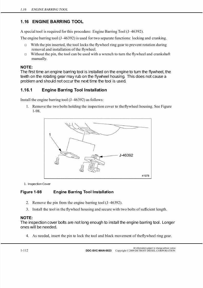
7/22/2019 Manual Mbe 4000 Taller
http://slidepdf.com/reader/full/manual-mbe-4000-taller 156/630
1.16 ENGINE BARRING TOOL
1.16 ENGINE BARRING TOOL
A special tool is required for this procedure: Engine Barring Tool (J–46392).
The engine barring tool (J–46392) is used for two separate functions: locking and cranking.
□ With the pin inserted, the tool locks the flywheel ring gear to prevent rotation during
removal and installation of the flywheel.□ Without the pin, the tool can be used with a wrench to turn the flywheel and crankshaft
manually.
NOTE: The first time an engine barring tool is installed on the engine to turn the flywheel, theteeth on the rotating gear may rub on the flywheel housing. This does not cause aproblem and should not occur the next time the tool is used.
1.16.1 Engine Barring Tool Installation
Install the engine barring tool (J–46392) as follows:1. Remove the two bolts holding the inspection cover to the flywheel housing. See Figure
1-98.
1. Inspection Cover
Figure 1-98 Engine Barring Tool Installation
2. Remove the pin from the engine barring tool (J–46392).
3. Install the tool in the flywheel housing and secure with two bolts of suf ficient length.
NOTE: The inspection cover bolts are not long enough to install the engine barring tool. Longerones will be needed.
4. As needed, insert the pin to lock the tool and block movement of the flywheel ring gear.
All information subject to change without notice.
1-112 DDC-SVC-MAN-0023 Copyright © 2009 DETROIT DIESEL CORPORATION
7/22/2019 Manual Mbe 4000 Taller
http://slidepdf.com/reader/full/manual-mbe-4000-taller 157/630
MBE 4000 SERVICE MANUAL
1.16.2 Engine Barring Tool Removal
Remove the engine barring tool (J–46392) as follows:
NOTICE:
The engine barring tool must be removed from the timing case
before starting the engine. Failure to do so could damage theflywheel ring gear.
1. Remove the two bolts and the barring tool from the flywheel housing. It is not necessary
to remove the pin.
2. Install the inspection cover on the flywheel housing with the two bolts. Tighten the bolts
25 N·m (18 lb·ft).
All information subject to change without notice.
DDC-SVC-MAN-0023 Copyright © 2009 DETROIT DIESEL CORPORATION 1-113

7/22/2019 Manual Mbe 4000 Taller
http://slidepdf.com/reader/full/manual-mbe-4000-taller 158/630
1.17 FLYWHEEL HOUSING
1.17 FLYWHEEL HOUSING
See Figure 1-99 for an exploded view of the flywheel housing assembly.
1. Flywheel 4. Flywheel Housing 7. Crankshaft Gear
2. Flywheel Housing Mounting Bolt 5. Gasket 8. Starter
3. CamshaftPosition (CMP) Sensor 6. Camshaft Gear 9. Rear Radial Seal
Figure 1-99 Flywheel Housing Assembly (exploded view)
1.17.1 Flywheel Housing Removal
Remove the flywheel housing as follows:
1. Remove the flywheel. Refer to section 1.13.1.
2. Remove the oil pan and gasket.
3. Support the engine by placing suitable jack stands under the cylinder block pan rails.
Make sure not to damage the sealing surfaces of the pan rails.
4. Remove the rear engine mounts from thefl
ywheel housing. Refer to appropriate vehicleservice manual.
5. Remove the starter from the flywheel housing.
6. Disconnect the Hengst® crankcase breather piping from the flywheel housing.
7. Remove the flywheel housing mounting bolts. Then remove the flywheel housing from
the cylinder block. See Figure 1-99.
8. Remove and discard the flywheel housing gasket.
All information subject to change without notice.
1-114 DDC-SVC-MAN-0023 Copyright © 2009 DETROIT DIESEL CORPORATION
7/22/2019 Manual Mbe 4000 Taller
http://slidepdf.com/reader/full/manual-mbe-4000-taller 159/630
MBE 4000 SERVICE MANUAL
1.17.2 Flywheel Housing Installation
Install the flywheel housing as follows:
1. Check the flywheel housing for damage.
2. Install a new rear radial seal. Refer to section 1.8.2.
3. Using a suitable scraper, such as a putty knife, clean the mating sur faces of the cylinder block and the flywheel housing. Remove any dirt or grease, and all traces of old sealant.
4. Install the flywheel housing and new gasket onto cylinder block and secure with bolts.
Torque the bolts to 70 N·m (52 lb·ft).
5. Install the starter onto the flywheel housing. Torque the bolts to 80 N·m (59 lb·ft).
6. Connect the Hengst® crankcase breather piping to the flywheel housing.
7. Install the flywheel. Refer to section 1.13.2.
8. Install the rear engine mounts onto the flywheel housing. Refer to appropriate vehicle
service manual.
9. Install the oil pan and new gasket.
10. Install the transmission and clutch. Refer to appropriate vehicle service manual.
All information subject to change without notice.
DDC-SVC-MAN-0023 Copyright © 2009 DETROIT DIESEL CORPORATION 1-115

7/22/2019 Manual Mbe 4000 Taller
http://slidepdf.com/reader/full/manual-mbe-4000-taller 160/630
1.18 PISTON, PISTON RING, AND CONNECTING ROD
1.18 PISTON, PISTON RING, AND CONNECTING ROD
The pistons are made of aluminum alloy with ring carriers and a shallow combustion ch amber
recess. The pistons are cooled by oil spray nozzles. See Figure 1-100 for an exploded view
of the piston and connecting rod assembly.
1. Piston and Rings 4. Connecting Rod 7. Bearing Shell
2. Wrist Pin 5. Bearing Cap
3. Snap Ring 6. Connecting R od S tretch Bolt
Figure 1-100 Piston Assembly (exploded view)
1.18.1 Piston Removal
Remove the piston assembly as follows:
1. Remove each cylinder head, as required. Refer to section 1.2.1.
NOTE: The MBE 4000 engine has individual heads for each cylinder. To remove one piston,do these procedures step by step. To remove all the pistons, repeat each step in theseinstructions, as applicable, for all six pistons.
2. Remove the oil pan.
NOTICE:Do not damage the piston travel surface of the cylinder.
3. Using a plastic scraping tool, carefully scrape off any combustion residues from the
combustion area in the cylinder in order to avoid damage to the piston rings when the
piston is removed.
4. Install the engine barring tool (J–46392). Refer to section 1.16.1.
All information subject to change without notice.
1-116 DDC-SVC-MAN-0023 Copyright © 2009 DETROIT DIESEL CORPORATION
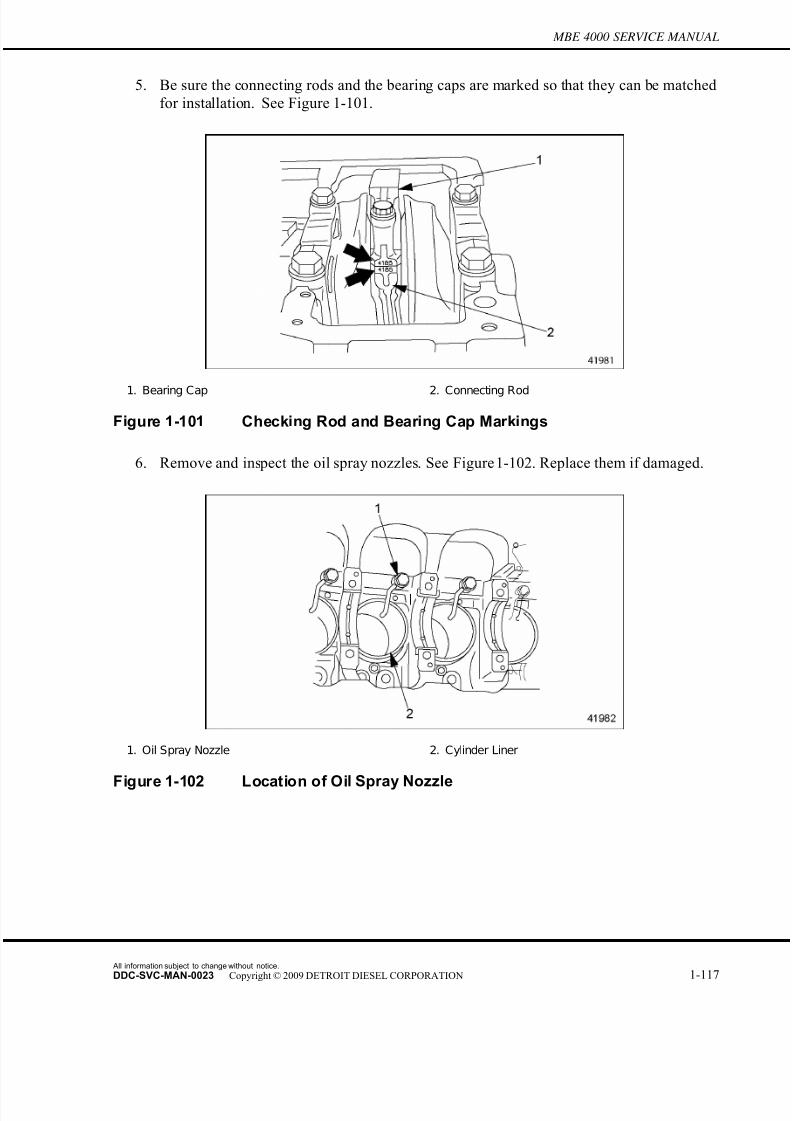
7/22/2019 Manual Mbe 4000 Taller
http://slidepdf.com/reader/full/manual-mbe-4000-taller 161/630
MBE 4000 SERVICE MANUAL
5. Be sure the connecting rods and the bearing caps are marked so that they can be matched
for installation. See Figure 1-101.
1. Bearing Cap 2. Connecting Rod
Figure 1-101 Checking Rod and Bearing Cap Markings
6. Remove and inspect the oil spray nozzles. See Figure 1-102. Replace them if damaged.
1. Oil Spray Nozzle 2. Cylinder Liner
Figure 1-102 Location of Oil Spray Nozzle
All information subject to change without notice.
DDC-SVC-MAN-0023 Copyright © 2009 DETROIT DIESEL CORPORATION 1-117

7/22/2019 Manual Mbe 4000 Taller
http://slidepdf.com/reader/full/manual-mbe-4000-taller 162/630
1.18 PISTON, PISTON RING, AND CONNECTING ROD
7. Remove the connecting rod stretch bolts and bearing cap. See Figure 1-103.
Figure 1-103 Removing the Bearing Caps
NOTE:If the bearing shell halves are removed from the rods and caps, be sure to mark themso they can be matched for installation.
8. Remove the bearing shell halves from the bearing cap and connecting rod.
9. Push the piston and connecting rod out of the cylinder, and remove them both from the
cylinder block.
10. Secure the connecting rod in a vise with protective jaws.
NOTICE:
Be sure the vise jaws are adequately lined to prevent the rodsurface from being nicked or marred in any way. Such surfacedamage could lead to later rod cracking or breaking.
11. Remove the piston rings from the piston. Refer to section 1.18.3.
12. Remove the wrist-pin snap rings. Push the wrist pin out and remove the piston from
the connecting rod.
1.18.1.1 Piston Inspection
Inspect the piston as follows:
1. Remove the piston. Refer to section 1.18.1.
All information subject to change without notice.
1-118 DDC-SVC-MAN-0023 Copyright © 2009 DETROIT DIESEL CORPORATION

7/22/2019 Manual Mbe 4000 Taller
http://slidepdf.com/reader/full/manual-mbe-4000-taller 163/630
MBE 4000 SERVICE MANUAL
2. Check the diameter of the wrist pin and the wrist pin bore. See Figure 1-104.
Specifications are listed in Table 1-26.
1. Piston and Rings 4. Connecting Rod 7. Bearing Shell
2. Wrist Pin 5. Bearing Cap
3. Snap Ring 6. Connecting R od S tretch Bolt
Figure 1-104 Piston Assembly (exploded view)
Description Dimensions: mm (in.)
P iston C ompression Height 79.50-79.55 (3.130-3.132)
Wrist P in Bore Diameter 52.03-52.04 (2.0484-2.0488)
Wrist P in Diameter 51.992-51.998 (2.0469-2.0472)
Table 1-26 Piston Inspection Specifications
3. Inspect the cylinder liner and piston for damage and signs of wear. Replace any piston
with damage to the snap ring grooves, cracks in the piston wall, or signs of seizing
and/or erosion.
All information subject to change without notice.
DDC-SVC-MAN-0023 Copyright © 2009 DETROIT DIESEL CORPORATION 1-119

7/22/2019 Manual Mbe 4000 Taller
http://slidepdf.com/reader/full/manual-mbe-4000-taller 164/630
1.18 PISTON, PISTON RING, AND CONNECTING ROD
4. Check the tolerance code on the piston and compare it to the tolerance code on the
cylinder liner. See Figure 1-105.
1. Piston 2. Cylinder Liner
Figure 1-105 Tolerance Codes
5. Check the condition of the piston rings. Replace any worn, damaged, or chipped rings.
Refer to section 1.18.3.
6. Check the connecting rod for any unusual condition. Refer to section 1.18.1.2.
7. Measure the diameters of the bearing shell bore and crankshaft journals. Refer to section
1.18.1.3 for instructions.
8. Check the length of the connecting rod stretch bolts. See Figure 1-106. Replace any bolts
that exceed the maximum length of 68.5 mm (2.70 in.).
1. Shank
Figure 1-106 Measuring a Stretch Bolt
All information subject to change without notice.
1-120 DDC-SVC-MAN-0023 Copyright © 2009 DETROIT DIESEL CORPORATION
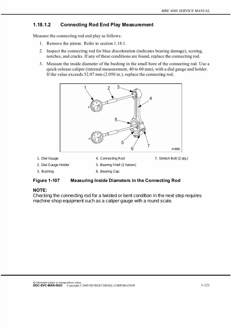
7/22/2019 Manual Mbe 4000 Taller
http://slidepdf.com/reader/full/manual-mbe-4000-taller 165/630
MBE 4000 SERVICE MANUAL
1.18.1.2 Connecting Rod End Play Measurement
Measure the connecting rod end play as follows:
1. Remove the piston. Refer to section 1.18.1.
2. Inspect the connecting rod for blue discoloration (indicates bearing damage), scoring,
notches, and cracks. If any of these conditions are found, replace t he connecting rod.3. Measure the inside diameter of the bushing in the small bore of the connecting rod. Use a
quick-release caliper (internal measurement, 40 to 60 mm), with a dial gauge and holder.
If the value exceeds 52.07 mm (2.050 in.), replace the connecting rod.
1. Dial Gauge 4. Connecting Rod 7. Stretch Bolt (2 qty.)
2. Dial Gauge Holder 5. Bearing Shell (2 halves)
3. Bushing 6. Bearing Cap
Figure 1-107 Measuring Inside Diameters in the Connecting Rod
NOTE:Checking the connecting rod for a twisted or bent condition in the next step requiresmachine shop equipment such as a caliper gauge with a round scale.
All information subject to change without notice.
DDC-SVC-MAN-0023 Copyright © 2009 DETROIT DIESEL CORPORATION 1-121
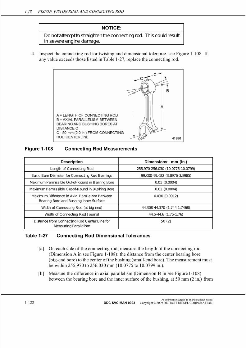
7/22/2019 Manual Mbe 4000 Taller
http://slidepdf.com/reader/full/manual-mbe-4000-taller 166/630
1.18 PISTON, PISTON RING, AND CONNECTING ROD
NOTICE:
Do notattemptto straighten theconnecting rod. This could resultin severe engine damage.
4. Inspect the connecting rod for twisting and dimensional tolerance. see Figure 1-108. If
any value exceeds those listed in Table 1-27, replace the connecting rod.
Figure 1-108 Connecting Rod Measurements
Description Dimensions: mm (in.)
Length of Connecting Rod 255.970-256.030 (10.0775-10.0799)
Basic Bore Diameter for Connecting Rod Bearings 99.000-99.022 (3.8976-3.8985)
Maximum Permissible Out-of-Round in Bearing Bore 0.01 (0.0004)
Maximum Permissible Out-of-Round in Bushing Bore 0.01 (0.0004)
Maximum Difference in Axial Parallelism Between
Bearing Bore and Bushing Inner Surface
0.030 (0.0012)
Width of Connecting Rod (at big end) 44.308-44.370 (1.744-1.7468)
Width of C onnecting R od J ournal 44.5-44.6 (1.75-1.76)
Distance from Connecting Rod Center Line for
Measuring Parallelism
50 (2)
Table 1-27 Connecting Rod Dimensional Tolerances
[a] On each side of the connecting rod, measure the length of the connecting rod
(Dimension A in see Figure 1-108): the distance from the center bearing bore
(big-end bore) to the center of the bushing (small-end bore). The measurement must
be within 255.970 to 256.030 mm (10.0775 to 10.0799 in.).
[b] Measure the difference in axial parallelism (Dimension B in see Figure 1-108)
between the bearing bore and the inner surface of the bushing, at 50 mm (2 in.) from
All information subject to change without notice.
1-122 DDC-SVC-MAN-0023 Copyright © 2009 DETROIT DIESEL CORPORATION

7/22/2019 Manual Mbe 4000 Taller
http://slidepdf.com/reader/full/manual-mbe-4000-taller 167/630
MBE 4000 SERVICE MANUAL
the connecting-rod centerline (Dimension C in see Figure 1-108). The maximum
allowed difference is 0.030 mm (0.0012 in.).
[c] Measure the diameter of the connecting rod basic bore, with the bearing shells
removed. The diameter of the basic bore must be between 99.000 to 99.022 mm
(3.8976 to 3.8985 in.).
[d] Measure the maximum permissible out-of-round in the bearing bore, with the bearingshells removed. The maximum permissible is 0.01 mm (0.0004 in.).
5. Calculate the connecting rod end play, or axial play, (fore-to-aft movement) on the
crankshaft.If the end play is less than 0.130 mm (0.0051 in.), or more than 0.292 mm
(0.0115 in.), replace the connecting rod. Listed in Table 1-27.
[a] For each bearing journal, note the width (thickness) of the bearing journal. Example:
W j
= 1.8120 inches.
[b] For each connecting rod, note the width (thickness) of the rod. Example: Wr
=
1.8050 inches.
[c] From the value for the journal width, subtract the value for the connecting rod width.
This result is the end play. Example: W j —W
r = 0.0070 inch.
6. Remove the bolts and bearing cap when r eady to install the piston.
7. Install the piston. Refer to section 1.18.2.
1.18.1.3 Connecting Rod Radial Play Measurement
Measure the connecting rod radial play as follows:
1. Remove the piston. Refer to section 1.18.1.
2. Using a chamois cloth, clean the bearing bores in both the connecting rod and the bearingcap.
All information subject to change without notice.
DDC-SVC-MAN-0023 Copyright © 2009 DETROIT DIESEL CORPORATION 1-123
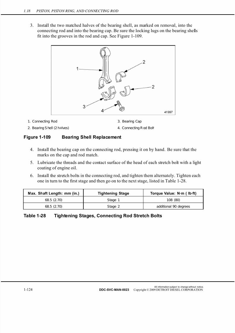
7/22/2019 Manual Mbe 4000 Taller
http://slidepdf.com/reader/full/manual-mbe-4000-taller 168/630
1.18 PISTON, PISTON RING, AND CONNECTING ROD
3. Install the two matched halves of the bearing shell, as marked on removal, into the
connecting rod and into the bearing cap. Be sure the locking lugs on the bearing shel ls
fit into the grooves in the rod and cap. See Figure 1-109.
1. Connecting Rod 3. Bearing Cap
2. Bearing S hell (2 halves) 4. Connecting R od Bolt
Figure 1-109 Bearing Shell Replacement
4. Install the bearing cap on the connecting rod, pressing it on by hand. Be sure that the
marks on the cap and rod match.
5. Lubricate the threads and the contact surface of the head of each stretch bolt with a light
coating of engine oil.
6. Install the stretch bolts in the connecting rod, and tighten them alternately. Tighten eachone in turn to the first stage and then go on to the next stage, listed in Table 1-28.
Max. Shaft Length: mm (in.) Tightening Stage Torque Value: N·m ( lb·ft)
68.5 (2.70) Stage 1 108 (80)
68.5 (2.70) Stage 2 additional 90 degrees
Table 1-28 Tightening Stages, Connecting Rod Stretch Bolts
All information subject to change without notice.
1-124 DDC-SVC-MAN-0023 Copyright © 2009 DETROIT DIESEL CORPORATION
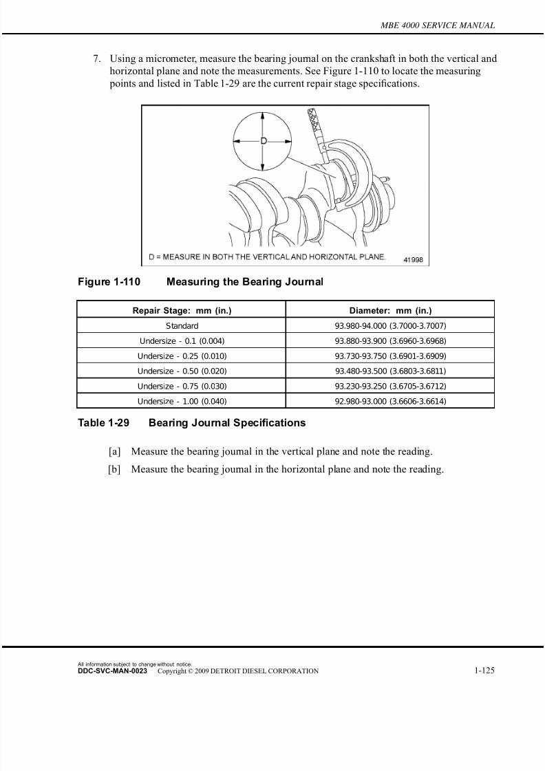
7/22/2019 Manual Mbe 4000 Taller
http://slidepdf.com/reader/full/manual-mbe-4000-taller 169/630
MBE 4000 SERVICE MANUAL
7. Using a micrometer, measure the bearing journal on the crankshaft in both the vertical and
horizontal plane and note the measurements. See Figure 1-110 to locate the measuring
points and listed in Table 1-29 are the current repair stage specifications.
Figure 1-110 Measuring the Bearing Journal
Repair Stage: mm (in.) Diameter: mm (in.)
Standard 93.980-94.000 (3.7000-3.7007)
Undersize - 0.1 (0.004) 93.880-93.900 (3.6960-3.6968)
Undersize - 0.25 (0.010) 93.730-93.750 (3.6901-3.6909)
Undersize - 0.50 (0.020) 93.480-93.500 (3.6803-3.6811)
Undersize - 0.75 (0.030) 93.230-93.250 (3.6705-3.6712)
Undersize - 1.00 (0.040) 92.980-93.000 (3.6606-3.6614)
Table 1-29 Bearing Journal Specifications
[a] Measure the bearing journal in the vertical plane and note the reading.
[b] Measure the bearing journal in the horizontal plane and note the reading.
All information subject to change without notice.
DDC-SVC-MAN-0023 Copyright © 2009 DETROIT DIESEL CORPORATION 1-125
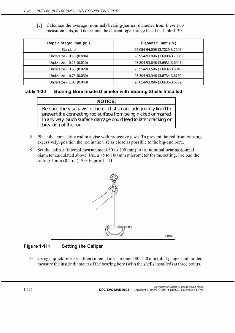
7/22/2019 Manual Mbe 4000 Taller
http://slidepdf.com/reader/full/manual-mbe-4000-taller 170/630
1.18 PISTON, PISTON RING, AND CONNECTING ROD
[c] Calculate the average (nominal) bearing-journal diameter from these two
measurements, and determine the current repair stage listed in Table 1-30.
Repair Stage: mm (in.) Diameter: mm (in.)
Standard 94.054-94.096 (3.7029-3.7046)
Undersize - 0.10 (0.004) 93.954-93.996 (3.6990-3.7006)
Undersize - 0.25 (0.010) 93.804-93.846 (3.6931-3.6947)
Undersize - 0.50 (0.020) 93.554-93.596 (3.6832-3.6848)
Undersize - 0.75 (0.030) 93.304-93.346 (3.6734-3.6750)
Undersize - 1.00 (0.040) 93.054-93.096 (3.6635-3.6652)
Table 1-30 Bearing Bore Inside Diameter with Bearing Shells Installed
NOTICE:
Be sure the vise jaws in the next step are adequately lined toprevent the connecting rod surface frombeing nicked or marredin any way. Such surface damage could lead to later cracking orbreaking of the rod.
8. Place the connecting rod in a vise with protective jaws. To prevent the rod from twisting
excessively, position the r od in the vise as close as possible to the big-end bore.
9. Set the caliper (internal measurement 80 to 100 mm) to the nominal bearing-journal
diameter calculated above. Use a 75 to 100 mm micrometer for the setting. Preload the
setting 5 mm (0.2 in.). See Figure 1-111.
Figure 1-111 Setting the Caliper
10. Using a quick-release caliper (internal measurement 80-120 mm), dial gauge, and holder,
measure the inside diameter of the bearing bore (with the shells installed) at three points.
All information subject to change without notice.
1-126 DDC-SVC-MAN-0023 Copyright © 2009 DETROIT DIESEL CORPORATION

7/22/2019 Manual Mbe 4000 Taller
http://slidepdf.com/reader/full/manual-mbe-4000-taller 171/630
MBE 4000 SERVICE MANUAL
Measure vertically and about 60 degrees each side of vertical. See Figure 1-112 to locate
the measuring points, and find the current specifications listed in Table 1-30.
1. Bolt 2. Bearing Cap
Figure 1-112 Measuring the Inside Diameter of the Bearing Shell
[a] Measure the bearing bore in the vertical dimension and note the reading.
[b] Mark off a point 60 degrees counterclockwise from vertical. Measure the bearing
bore in this dimension and note the reading.
[c] Mark off a point 60 degrees clockwise from vertical. Measure the bearing bore
in this dimension and note the reading.
[d] Calculate the average (nominal) bearing-journal diameter from these three
measurements, and determine the current repair stage listed in Table 1-30. If any of the measurements are out of tolerance, replace the bearing shells.
NOTE:Connecting-rod bearings for all repair stages are delivered from the factory ready toinstall. Do not refinish them in any way.
NOTE: To obtain a correct value for connecting-rod radial play, the diameters of each bearingbore and its corresponding journal must belong to the same repair stage (both mustbe "standard," "undersize 0.1 mm," etc.).
All information subject to change without notice.
DDC-SVC-MAN-0023 Copyright © 2009 DETROIT DIESEL CORPORATION 1-127
7/22/2019 Manual Mbe 4000 Taller
http://slidepdf.com/reader/full/manual-mbe-4000-taller 172/630
1.18 PISTON, PISTON RING, AND CONNECTING ROD
11. Calculate the connecting rod radial play (up-and-down movement) at the bearing journal.
If the radial play is less than 0.054 mm (0.0021 in.), or more than 0.116 mm (0.0046 in .),
replace the connecting rod. Listed in Table 1-31 is the radial play.
Description Dimensions: mm (in.)
Radial Play 0.054 - 0.116 (0.0021 - 0.0046)
Table 1-31 Connecting Rod Radial Play
[a] For each connecting rod, note the average value for the bearing bore diameter, as
calculated. Example: Ds
= 3.5421 inches.
[b] For each bearing journal, note the average value for the bearing journal diameter, as
calculated. Example: D j= 3.5391 inches.
[c] From the value for the bearing bore diameter, subtract the value for the bearing
journal diameter. This result is the radial play. Example: Ds —D
j= 0.0030 inch.
NOTE:In the above example, both measurements belonged to repair stage "undersize 0.1 mm."
12. Remove the bearing cap from the connecting rod.
13. Install the piston. Refer to section 1.18.2.
1.18.2 Piston Installation
Install the piston assembly as follows:
1. Position the connecting rod in the piston so that the longer end side is on the unit pump
side.
All information subject to change without notice.
1-128 DDC-SVC-MAN-0023 Copyright © 2009 DETROIT DIESEL CORPORATION
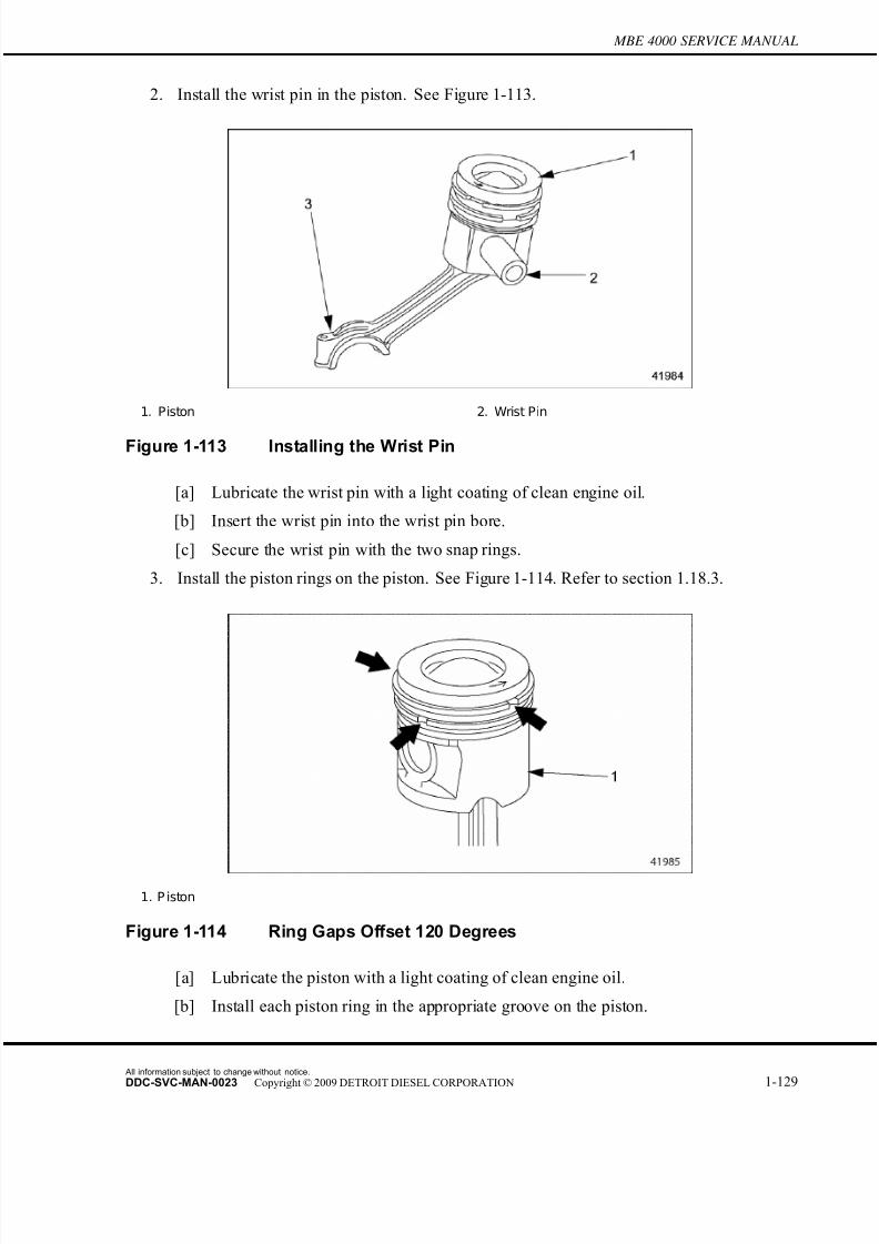
7/22/2019 Manual Mbe 4000 Taller
http://slidepdf.com/reader/full/manual-mbe-4000-taller 173/630
MBE 4000 SERVICE MANUAL
2. Install the wrist pin in the piston. See Figure 1-113.
1. Piston 2. Wrist Pin
Figure 1-113 Installing the Wrist Pin
[a] Lubricate the wrist pin with a light coating of clean engine oil.
[b] Insert the wrist pin into the wrist pin bore.
[c] Secure the wrist pin with the two snap rings.
3. Install the piston rings on the piston. See Figure 1-114. Refer to section 1.18.3.
1. P iston
Figure 1-114 Ring Gaps Offset 120 Degrees
[a] Lubricate the piston with a light coating of clean engine oil.
[b] Install each piston ring in the appropriate groove on the piston.
All information subject to change without notice.
DDC-SVC-MAN-0023 Copyright © 2009 DETROIT DIESEL CORPORATION 1-129
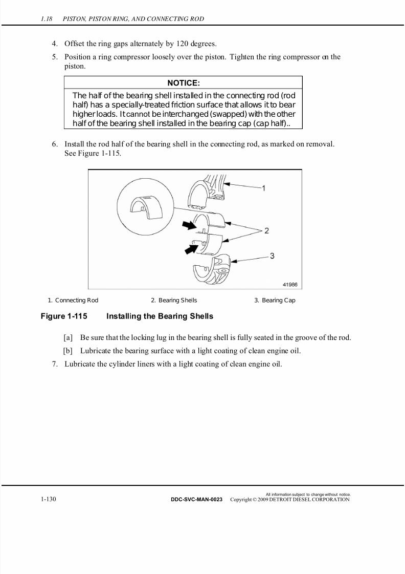
7/22/2019 Manual Mbe 4000 Taller
http://slidepdf.com/reader/full/manual-mbe-4000-taller 174/630
1.18 PISTON, PISTON RING, AND CONNECTING ROD
4. Offset the ring gaps alternately by 120 degrees.
5. Position a ring compressor loosely over the piston. Tighten the ring compressor on the
piston.
NOTICE:
The half of the bearing shell installed in the connecting rod (rodhalf) has a specially-treated friction surface that allows it to bearhigher loads. It cannot be interchanged (swapped) with the otherhalf of the bearing shell installed in the bearing cap (cap half)..
6. Install the rod half of the bearing shell in the connecting rod, as marked on removal.
See Figure 1-115.
1. Connecting Rod 2. Bearing Shells 3. Bearing Cap
Figure 1-115 Installing the Bearing Shells
[a] Be sure that the lock ing lug in the bearing shell is fully seated in the groove of the rod.
[b] Lubricate the bearing surface with a light coating of clean engine oil.
7. Lubricate the cylinder liners with a light coating of clean engine oil.
All information subject to change without notice.
1-130 DDC-SVC-MAN-0023 Copyright © 2009 DETROIT DIESEL CORPORATION
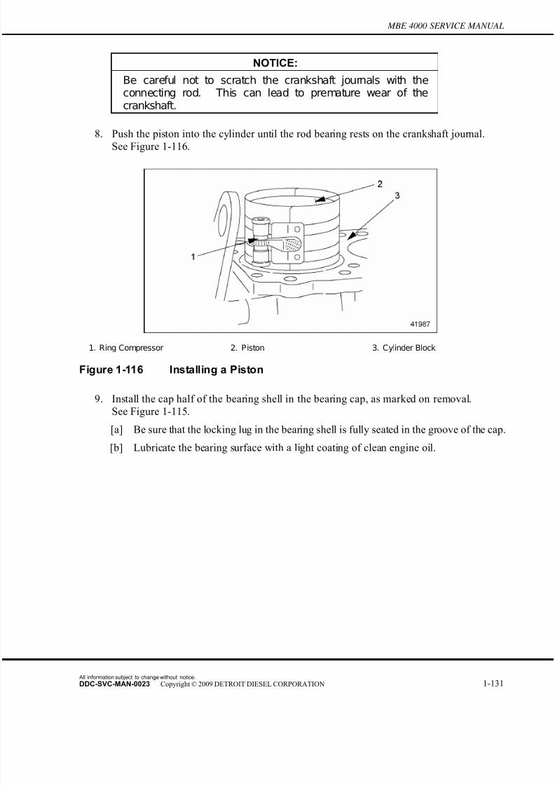
7/22/2019 Manual Mbe 4000 Taller
http://slidepdf.com/reader/full/manual-mbe-4000-taller 175/630
MBE 4000 SERVICE MANUAL
NOTICE:
Be careful not to scratch the crankshaft journals with theconnecting rod. This can lead to premature wear of thecrankshaft.
8. Push the piston into the cylinder until the rod bearing rests on the crankshaft journal.See Figure 1-116.
1. Ring Compressor 2. Piston 3. Cylinder Block
Figure 1-116 Installing a Piston
9. Install the cap half of the bearing shell in the bearing cap, as marked on removal.
See Figure 1-115.[a] Be sure that the locking lug in the bearing shell is fully seated in the groove of the cap.
[b] Lubricate the bearing surface with a light coating of clean engine oil.
All information subject to change without notice.
DDC-SVC-MAN-0023 Copyright © 2009 DETROIT DIESEL CORPORATION 1-131
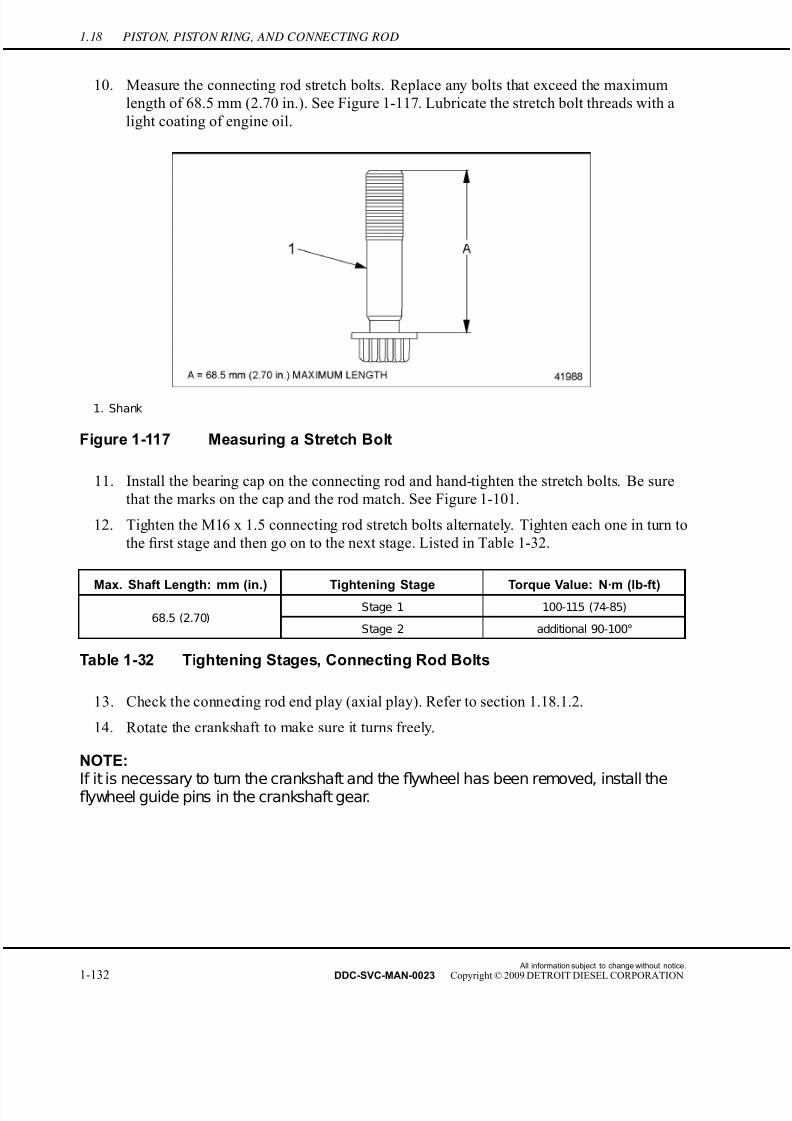
7/22/2019 Manual Mbe 4000 Taller
http://slidepdf.com/reader/full/manual-mbe-4000-taller 176/630
1.18 PISTON, PISTON RING, AND CONNECTING ROD
10. Measure the connecting rod stretch bolts. Replace any bolts that exceed the maximum
length of 68.5 mm (2.70 in.). See Figure 1-117. Lubricate the stretch bolt threads with a
light coating of engine oil.
1. Shank
Figure 1-117 Measuring a Stretch Bolt
11. Install the bearing cap on the connecting rod and hand-tighten the stretch bolts. Be sure
that the marks on the cap and the rod match. See Figure 1-101.
12. Tighten the M16 x 1.5 connecting rod stretch bolts alternately. Tighten each one in turn to
the first stage and then go on to the next stage. Listed in Table 1-32.
Max. Shaft Length: mm (in.) Tightening Stage Torque Value: N·m (lb-ft)Stage 1 100-115 (74-85)
68.5 (2.70)Stage 2 additional 90-100°
Table 1-32 Tightening Stages, Connecting Rod Bolts
13. Check the connecting rod end play (axial play). Refer to section 1.18.1.2.
14. Rotate the crankshaft to make sure it turns freely.
NOTE:
If it is necessary to turn the crankshaft and thefl
ywheel has been removed, install theflywheel guide pins in the crankshaft gear.
All information subject to change without notice.
1-132 DDC-SVC-MAN-0023 Copyright © 2009 DETROIT DIESEL CORPORATION
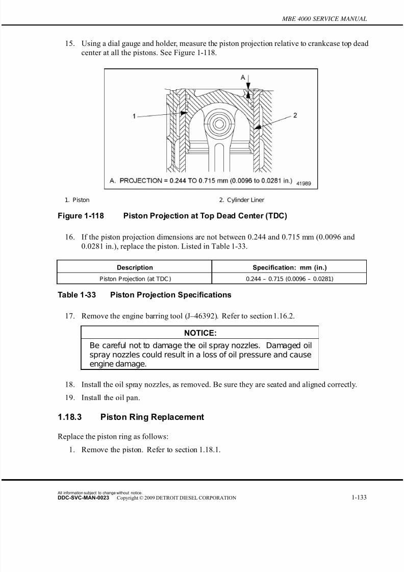
7/22/2019 Manual Mbe 4000 Taller
http://slidepdf.com/reader/full/manual-mbe-4000-taller 177/630
MBE 4000 SERVICE MANUAL
15. Using a dial gauge and holder, measure the piston projection relative to crankcase top dead
center at all the pistons. See Figure 1-118.
1. Piston 2. Cylinder Liner
Figure 1-118 Piston Projection at Top Dead Center (TDC)
16. If the piston projection dimensions are not between 0.244 and 0.715 mm (0.0096 and
0.0281 in.), replace the piston. Listed in Table 1-33.
Description Specification: mm (in.)
P iston P rojection (at TDC ) 0.244 – 0.715 (0.0096 – 0.0281)
Table 1-33 Piston Projection Specifications
17. Remove the engine barring tool (J–46392). Refer to section 1.16.2.
NOTICE:
Be careful not to damage the oil spray nozzles. Damaged oilspray nozzles could result in a loss of oil pressure and causeengine damage.
18. Install the oil spray nozzles, as removed. Be sure they are seated and aligned correctly.
19. Install the oil pan.
1.18.3 Piston Ring Replacement
Replace the piston ring as follows:
1. Remove the piston. Refer to section 1.18.1.
All information subject to change without notice.
DDC-SVC-MAN-0023 Copyright © 2009 DETROIT DIESEL CORPORATION 1-133
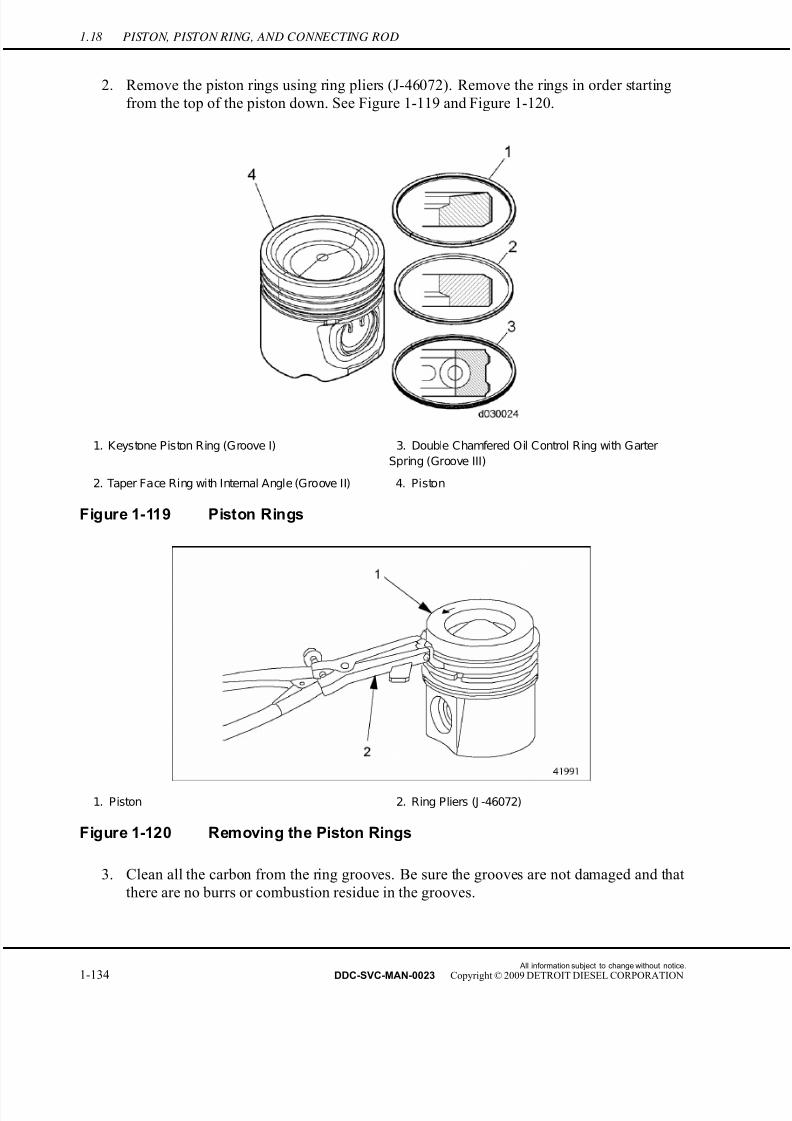
7/22/2019 Manual Mbe 4000 Taller
http://slidepdf.com/reader/full/manual-mbe-4000-taller 178/630
1.18 PISTON, PISTON RING, AND CONNECTING ROD
2. Remove the piston rings using ring pliers (J-46072). Remove the rings in order starting
from the top of the piston down. See Figure 1-119 and Figure 1-120.
1. Keystone Piston Ring (Groove I) 3. Double Chamfered Oil Control Ring with Garter
Spring (Groove III)
2. Taper Face Ring with Internal Angle (Groove II) 4. Piston
Figure 1-119 Piston Rings
1. Piston 2. Ring Pliers (J -46072)
Figure 1-120 Removing the Piston Rings
3. Clean all the carbon from the ring grooves. Be sure the grooves are not damaged and that
there are no burrs or combustion residue in the grooves.
All information subject to change without notice.
1-134 DDC-SVC-MAN-0023 Copyright © 2009 DETROIT DIESEL CORPORATION

7/22/2019 Manual Mbe 4000 Taller
http://slidepdf.com/reader/full/manual-mbe-4000-taller 179/630
MBE 4000 SERVICE MANUAL
4. Before installing the new rings, check the end gap. The correct end-gap measurements
are listed in Table 1-34.
Ring Designation GrooveGap When New
mm (in.)
Maximum End Gap
mm (in.)
Keystone I
0.45 to 0.60
(0.018 to 0.024) 1.0 (.039)
Taper-Faced with Internal
AngleII
0.40 to 0.55
(0.016 to 0.022)1.0 (.039)
Double-Chamfered Oil
Control with Garter SpringIII
0.40 to 0.55
(0.016 to 0.022)1.0 (.039)
Table 1-34 Piston Ring End-Gap Dimensions
NOTE:Check the end gap of the upper two piston ringsfirst. The garter spring must be removedfrom the third (lowest) piston ring before you can measure its end gap.
[a] Place each ring squarely into the combustion area of a cylinder liner or cylinder.
Measure the end gap using a feeler gauge. See Figure 1-121.
Figure 1-121 Checking the Ring End Gap
[b] Remove the spring garter from the third (lowest) ring. Measure its gap in the same
way as the other two rings.
All information subject to change without notice.
DDC-SVC-MAN-0023 Copyright © 2009 DETROIT DIESEL CORPORATION 1-135
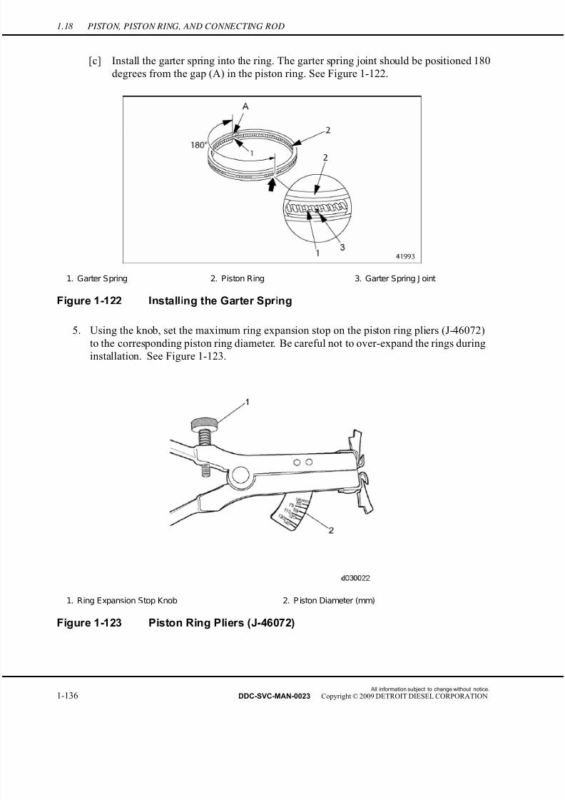
7/22/2019 Manual Mbe 4000 Taller
http://slidepdf.com/reader/full/manual-mbe-4000-taller 180/630
1.18 PISTON, PISTON RING, AND CONNECTING ROD
[c] Install the garter spring into the ring. The garter spring joint should be positioned 180
degrees from the gap (A) in the piston ring. See Figure 1-122.
1. Garter Spring 2. Piston Ring 3. Garter Spring J oint
Figure 1-122 Installing the Garter Spring
5. Using the knob, set the maximum ring expansion stop on the piston ring pliers (J-46072)
to the corresponding piston ring diameter. Be careful not to over-expand the rings during
installation. See Figure 1-123.
1. Ring Expansion Stop Knob 2. P iston Diameter (mm)
Figure 1-123 Piston Ring Pliers (J-46072)
All information subject to change without notice.
1-136 DDC-SVC-MAN-0023 Copyright © 2009 DETROIT DIESEL CORPORATION
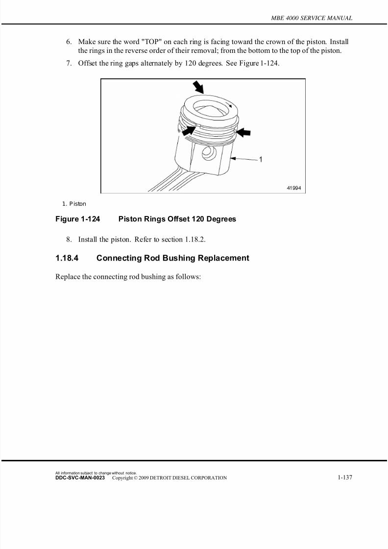
7/22/2019 Manual Mbe 4000 Taller
http://slidepdf.com/reader/full/manual-mbe-4000-taller 181/630
MBE 4000 SERVICE MANUAL
6. Make sure the word "TOP" on each ring is facing toward the crown of the piston. Install
the rings in the reverse order of their removal; from the bottom to the top of the piston.
7. Offset the ring gaps alternately by 120 degrees. See Figure 1-124.
1. P iston
Figure 1-124 Piston Rings Offset 120 Degrees
8. Install the piston. Refer to section 1.18.2.
1.18.4 Connecting Rod Bushing Replacement
Replace the connecting rod bushing as follows:
All information subject to change without notice.
DDC-SVC-MAN-0023 Copyright © 2009 DETROIT DIESEL CORPORATION 1-137
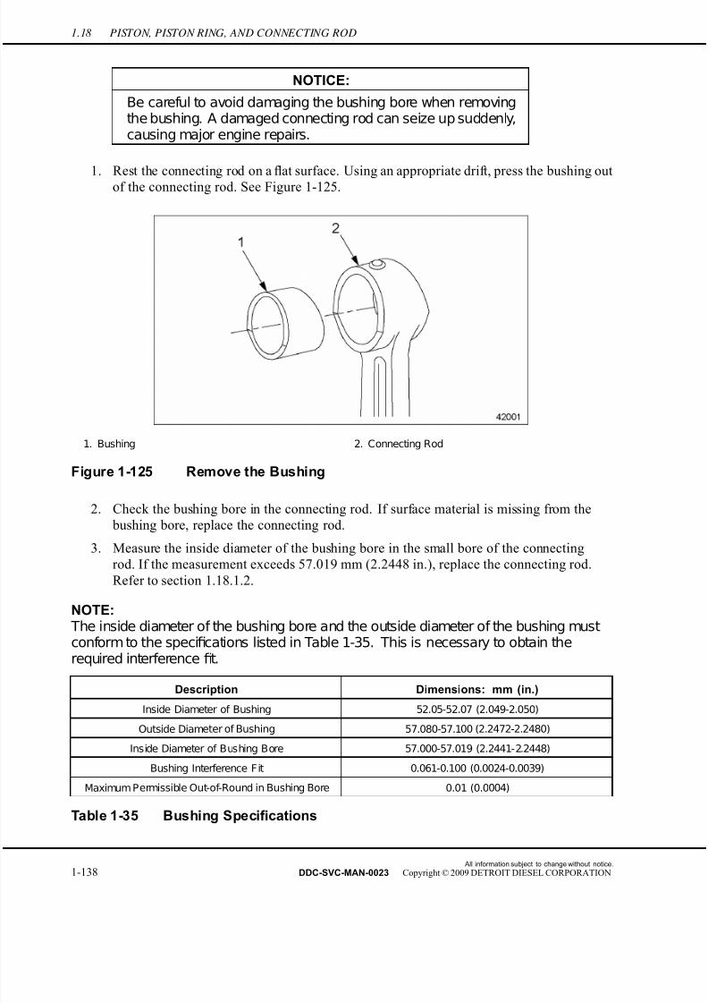
7/22/2019 Manual Mbe 4000 Taller
http://slidepdf.com/reader/full/manual-mbe-4000-taller 182/630
1.18 PISTON, PISTON RING, AND CONNECTING ROD
NOTICE:
Be careful to avoid damaging the bushing bore when removingthe bushing. A damaged connecting rod can seize up suddenly,causing major engine repairs.
1. Rest the connecting rod on afl
at surface. Using an appropriate drift, press the bushing outof the connecting rod. See Figure 1-125.
1. Bushing 2. Connecting Rod
Figure 1-125 Remove the Bushing
2. Check the bushing bore in the connecting rod. If surface material is missing from the
bushing bore, replace the connecting rod.3. Measure the inside diameter of the bushing bore in the small bore of the connecting
rod. If the measurement exceeds 57.019 mm (2.2448 in.), replace the connecting rod.
Refer to section 1.18.1.2.
NOTE: The inside diameter of the bushing bore and the outside diameter of the bushing mustconform to the specifications listed in Table 1-35. This is necessary to obtain therequired interference fit.
Description Dimensions: mm (in.)
Inside Diameter of Bushing 52.05-52.07 (2.049-2.050)
Outside Diameter of Bushing 57.080-57.100 (2.2472-2.2480)
Inside Diameter of Bushing Bore 57.000-57.019 (2.2441-2.2448)
Bushing Interference Fit 0.061-0.100 (0.0024-0.0039)
Maximum Permissible Out-of-Round in Bushing Bore 0.01 (0.0004)
Table 1-35 Bushing Specifications
All information subject to change without notice.
1-138 DDC-SVC-MAN-0023 Copyright © 2009 DETROIT DIESEL CORPORATION

7/22/2019 Manual Mbe 4000 Taller
http://slidepdf.com/reader/full/manual-mbe-4000-taller 183/630
MBE 4000 SERVICE MANUAL
4. Measure the outside diameter of the bushing. If the measurement exceeds 57.100 mm
(2.2480 in.), replace the bushing.
5. Measure the bushing bore in the connecting rod for deformation. If the bushing bore is
out-or-round by more than 0.01 mm (0.0004 in.), replace the connecting rod.
6. Rest the connecting rod on a flat surface. Using an appropriate drift, install the bushing in
the connecting rod.7. Measure the inside diameter of the bushing. If the measurement is shorter than 52.05 mm
(2.049 in.), machine the inside contact surface of the bushing until the measurement
is correct.
All information subject to change without notice.
DDC-SVC-MAN-0023 Copyright © 2009 DETROIT DIESEL CORPORATION 1-139

7/22/2019 Manual Mbe 4000 Taller
http://slidepdf.com/reader/full/manual-mbe-4000-taller 184/630
1.19 EGR PISTON, PISTON RING, AND CONNECTING ROD
1.19 EGR PISTON, PISTON RING, AND CONNECTING ROD
The difference from the non-EGR engine cylinder liner to the EGR engine, is a groove o n the
top part of the cylinder liner, which houses the carbon scraper ring. The EGR engine uses a
new tool for piston installation; however, all other procedures are the same for the EGR and
non-EGR engine.
1.19.1 Piston Removal for EGR Engine
Perform the following steps to remove the piston from an EGR engine:
NOTICE:
The carbon scraper ring has a smaller internal diameter thanthe piston skirt diameter; therefore, the piston installation andremoval must be carried out with the carbon scraper ringremoved.
NOTE:Piston removal in the EGR engine is performed with the engine facing upright – notturned on it's side.
1. Remove the carbon scraper ring from the cylinder liner groove.
1. Cylinder Liner 3. Installed Piston
2. Carbon Scraper Ring 4. Installed C arbon S craper Ring
Figure 1-126 Removing Carbon Scraper Ring
2. Push the piston and connecting rod assembly out of the cylinder liner.
3. Follow remaining steps for non-EGR engine piston removal. Refer to section 1.18.1.
All information subject to change without notice.
1-140 DDC-SVC-MAN-0023 Copyright © 2009 DETROIT DIESEL CORPORATION

7/22/2019 Manual Mbe 4000 Taller
http://slidepdf.com/reader/full/manual-mbe-4000-taller 185/630
MBE 4000 SERVICE MANUAL
1.19.2 Piston Installation for EGR Engine
Perform the following steps to install the piston in an EGR engine:
NOTICE:
The carbon scraper ring has a smaller internal diameter than
the piston skirt diameter; therefore, the piston installation andremoval must be carried out with the carbon scraper ringun-installed or removed.
NOTE:Piston installation in the EGR engine is performed with the engine facing upright – notturned on it's side.
1. Install sleeve (J–47110) to the cylinder block. See Figure 1-127.
1. P iston
Figure 1-127 Installation of Piston
NOTE: There are NO arrows on the top of the EGR piston to direct the installation. The pistoncan be installed in any direction and it will be correct.
2. Push the piston into cylinder liner, using ring compressor (J-45983) to compress the
piston rings.
3. Clean the carbon scraper ring seat in the cylinder liner.
4. After piston is installed, install carbon scraper ring in the cylinder liner groove. See Figure
1-126.
5. Check carbon scraper ring for correct fit after installation.
All information subject to change without notice.
DDC-SVC-MAN-0023 Copyright © 2009 DETROIT DIESEL CORPORATION 1-141

7/22/2019 Manual Mbe 4000 Taller
http://slidepdf.com/reader/full/manual-mbe-4000-taller 186/630
1.19 EGR PISTON, PISTON RING, AND CONNECTING ROD
6. Follow remaining steps for piston installation in a non-EGR engine . Refer to section
1.18.2 step 9.
All information subject to change without notice.
1-142 DDC-SVC-MAN-0023 Copyright © 2009 DETROIT DIESEL CORPORATION
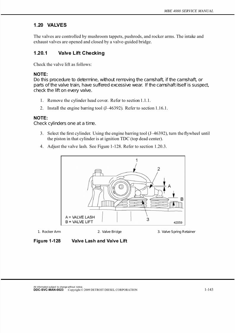
7/22/2019 Manual Mbe 4000 Taller
http://slidepdf.com/reader/full/manual-mbe-4000-taller 187/630
MBE 4000 SERVICE MANUAL
1.20 VALVES
The valves are controlled by mushroom tappets, pushrods, and rocker arms. The intak e and
exhaust valves are opened and closed by a valve-guided bridge.
1.20.1 Valve Lift Checking
Check the valve lift as follows:
NOTE:Do this procedure to determine, without removing the camshaft, if the camshaft, orparts of the valve train, have suffered excessive wear. If the camshaft itself is suspect,check the lift on every valve.
1. Remove the cylinder head cover. Refer to section 1.1.1.
2. Install the engine barring tool (J–46392). Refer to section 1.16.1.
NOTE:Check cylinders one at a time.
3. Select the first cylinder. Using the engine barring tool (J–46392), turn the flywheel until
the piston in that cylinder is at ignition TDC (top dead center).
4. Adjust the valve lash. See Figure 1-128. Refer to section 1.20.3.
1. Rocker Arm 2. Valve Bridge 3. Valve Spring Retainer
Figure 1-128 Valve Lash and Valve Lift
All information subject to change without notice.
DDC-SVC-MAN-0023 Copyright © 2009 DETROIT DIESEL CORPORATION 1-143

7/22/2019 Manual Mbe 4000 Taller
http://slidepdf.com/reader/full/manual-mbe-4000-taller 188/630
1.20 VALVES
5. Check the valve lift on the intake valves. See Figure 1-129. Listed in Table 1-36 are
the specifications.
1. Dial Gauge 3. Intake Rocker Arm 5. Intake Valve
2. Gauge Holder 4. Pushrod
Figure 1-129 Checking Valve Lift, Intake Valves
Description Specification: mm (in.)
Specified Dial Gauge P reload for Checking Valve Lift 15 (0.60)
Valve Lift with Intake Valves Completely Open 11.546 (at least 0.4546)
Valve Lift with Exhaust Valves Completely Open 11.963 (at least 0.4710)
Inspection Cover Bolt Torque 25 N·m (18 lb·ft)
Table 1-36 Valve Lift Specifications
[a] Mount a dial gauge and a gauge holder on the valve bridge. Mount the dial gauge
with a preload of a pproximately 15 mm (0.60 in.) to provide adequate travel for
checking the intake valve lift.
[b] Set the scale on the dial gauge to "0" (zero).
[c] Using the engine barring tool (J–46392), turn the flywheel in a counterclockwise
direction (as viewed from the flywheel end).
NOTE: The dial gauge will show the highest reading when the valve is completely open.
[d] When the valves are completely open, read off the value on the dial gauge. If the
intake valve lift reaches at least 11.546 mm (0.4546 in.) at its highest point, the
intake valves are lifting OK. Check the exhaust valves.If the intake valve lift fails to
All information subject to change without notice.
1-144 DDC-SVC-MAN-0023 Copyright © 2009 DETROIT DIESEL CORPORATION
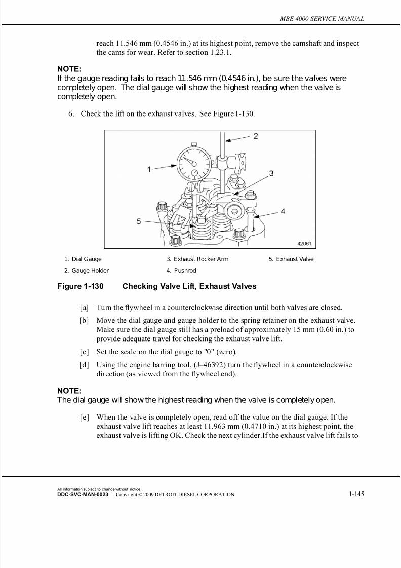
7/22/2019 Manual Mbe 4000 Taller
http://slidepdf.com/reader/full/manual-mbe-4000-taller 189/630
MBE 4000 SERVICE MANUAL
reach 11.546 mm (0.4546 in.) at its highest point, remove the camshaft and inspect
the cams for wear. Refer to section 1.23.1.
NOTE:If the gauge reading fails to reach 11.546 mm (0.4546 in.), be sure the valves werecompletely open. The dial gauge will show the highest reading when the valve is
completely open.
6. Check the lift on the exhaust valves. See Figure 1-130.
1. Dial Gauge 3. Exhaust Rocker Arm 5. Exhaust Valve
2. Gauge Holder 4. Pushrod
Figure 1-130 Checking Valve Lift, Exhaust Valves
[a] Turn the flywheel in a counter clockwise direction until both valves are closed.
[b] Move the dial gauge and gauge holder to the spring retainer on the exhaust valve.
Make sure the dial gauge still has a preload of approximately 15 mm (0.60 in.) to
provide adequate travel for checking the exhaust valve lift.
[c] Set the scale on the dial gauge to "0" (zero).
[d] Using the engine barring tool, (J–46392) turn the flywheel in a counterclockwise
direction (as viewed from the flywheel end).
NOTE:
The dial gauge will show the highest reading when the valve is completely open.
[e] When the valve is completely open, read off the value on the dial gauge. If the
exhaust valve lift reaches at least 11.963 mm (0.4710 in.) at its highest point, the
exhaust valve is lifting OK. Check the next cylinder.If the exhaust valve lift fails to
All information subject to change without notice.
DDC-SVC-MAN-0023 Copyright © 2009 DETROIT DIESEL CORPORATION 1-145

7/22/2019 Manual Mbe 4000 Taller
http://slidepdf.com/reader/full/manual-mbe-4000-taller 190/630
1.20 VALVES
reach 11.963 mm (0.4710 in.) at its highest point, remove the camshaft and inspect
the cams for wear. Refer to section 1.23.1.
NOTE:If the gauge reading fails to reach 11.963 mm (0.4710 in.), be sure the valves werecompletely open. The dial gauge will show the highest reading when the valve is
completely open.
7. Check the valve lift, both intake and exhaust, on the remaining cylinders, one at a time,
until all have been checked.
8. Remove the dial gauge and holder from the cylinder head.
9. Remove the engine barring tool (J–46392) from the flywheel housing. Refer to section
1.16.2.
10. Install the cylinder head cover. Refer to section 1.1.2.
1.20.2 Valve Lash Checking
Check and adjust the valve lash as follows:
NOTE:Adjust the valve lash when the engine is cold. Wait at least 30 minutes after shutdown,even if the engine ran only a short time.
Select a method for adjusting the valves. There are two acceptable methods for adjusting the
valves, prior to checking the valve lash:
□ In order, according to the timing sequence used for fuel injection (see Method One—Adjust
Each Cylinder in Firing Order);
□ By type of valve, depending on crankshaft position (see Method Two—Adjust All Valves
Using Two Crankshaft Positions).
All information subject to change without notice.
1-146 DDC-SVC-MAN-0023 Copyright © 2009 DETROIT DIESEL CORPORATION
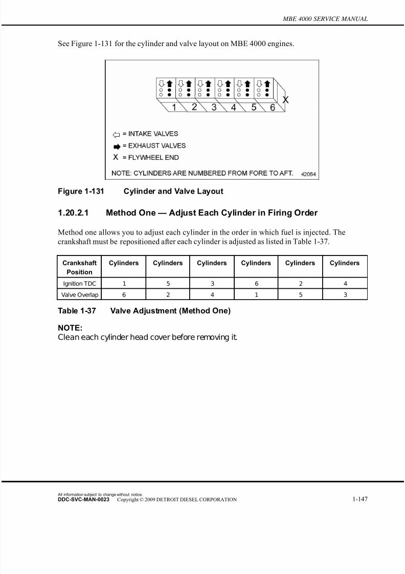
7/22/2019 Manual Mbe 4000 Taller
http://slidepdf.com/reader/full/manual-mbe-4000-taller 191/630
MBE 4000 SERVICE MANUAL
See Figure 1-131 for the cylinder and valve layout on MBE 4000 engines.
Figure 1-131 Cylinder and Valve Layout
1.20.2.1 Method One — Adjust Each Cylinder in Firing Order
Method one allows you to adjust each cylinder in the order in which fuel is injected. The
crankshaft must be repositioned af ter each cylinder is adjusted as listed in Table 1-37.
Crankshaft
Position
Cylinders Cylinders Cylinders Cylinders Cylinders Cylinders
Ignition TDC 1 5 3 6 2 4
Valve Overlap 6 2 4 1 5 3
Table 1-37 Valve Adjustment (Method One)
NOTE:Clean each cylinder head cover before removing it.
All information subject to change without notice.
DDC-SVC-MAN-0023 Copyright © 2009 DETROIT DIESEL CORPORATION 1-147

7/22/2019 Manual Mbe 4000 Taller
http://slidepdf.com/reader/full/manual-mbe-4000-taller 192/630
1.20 VALVES
1. Remove the cylinder head covers. See Figure 1-132. Refer to section 1.1.1.
1. Socket-Head Bolt 3. Gasket
2. Cylinder Head Cover 4. Cylinder Head
Figure 1-132 Cylinder Head Cover, (exploded view)
2. Remove the inspection cover on the flywheel housing.
3. Fit the engine barring tool (J–46392) into the inspection hole on the flywheel housing and
secure with bolts of suf ficient length. See Figure 1-133.
NOTE: The bolts fromthe inspection cover are notlong enough to secure the engine barring toolproperly. Use bolts of suf ficient length to secure the barring tool.
1. Inspection Cover 2. Cranking Device
Figure 1-133 Placement of the Barring Tool
All information subject to change without notice.
1-148 DDC-SVC-MAN-0023 Copyright © 2009 DETROIT DIESEL CORPORATION

7/22/2019 Manual Mbe 4000 Taller
http://slidepdf.com/reader/full/manual-mbe-4000-taller 193/630
MBE 4000 SERVICE MANUAL
4. For each cylinder, use the barring tool to turn over the crankshaft until the piston is exactly
at top dead center (TDC) in the compression stroke. The valves must be closed and it must
be possible to turn the pushrods without effort.
NOTE:When the piston in cylinder #1 is at ignition TDC, the valves of cylinder #6 will overlap,
meaning that both intake and exhaustvalves are partially open, and show no measurableplay when tested with a feeler gauge.
5. Check each valve and adjust it (if necessary), using the procedures under the headings
"Checking Valve Lash" and "Adjusting Valve Lash."
6. For each valve, measure the valve lash with a feeler gauge between the rocker arm and
valve bridge. It should be possible to pull the feeler gauge through with no more than
light resistance.
7. If the value measured is within the range given in the "Check For" column listed in Table
1-38, check the next valve.
Valve Type Check For: mm (in.) Adjust to: mm (in.)
Intake 0.30 to 0.60 (0.012 to 0.024) 0.40 (0.016)
Exhaust 0.50 to 0.80 (0.020 to 0.032) 0.60 (0.024)
Table 1-38 Valve Lash Checking and Adjustment
If the value measured is outside the range given in the "Check For" column listed in Table
1-38, adjust the valve lash.
1.20.2.2 Method Two — Adjust All Valves Using Two Crankshaft Positions
Method two allows you to adjust all the valves using just two crankshaft positions.
NOTE:Clean each cylinder head cover before removing it.
All information subject to change without notice.
DDC-SVC-MAN-0023 Copyright © 2009 DETROIT DIESEL CORPORATION 1-149

7/22/2019 Manual Mbe 4000 Taller
http://slidepdf.com/reader/full/manual-mbe-4000-taller 194/630
1.20 VALVES
1. Remove the cylinder head covers. See Figure 1-134. Refer to section 1.1.1.
1. Socket-Head Bolt 3. Gasket
2. Cylinder Head Cover 4. Cylinder Head
Figure 1-134 Cylinder Head Cover, (exploded view)
2. Remove the inspection cover on the flywheel housing.
3. Fit the engine barring tool (J–46392) into the inspection hole on the flywheel housing.
See Figure 1-135.
1. Inspection Cover 2. Cranking Device
Figure 1-135 Placement of the Barring Tool
All information subject to change without notice.
1-150 DDC-SVC-MAN-0023 Copyright © 2009 DETROIT DIESEL CORPORATION
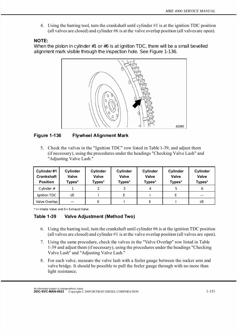
7/22/2019 Manual Mbe 4000 Taller
http://slidepdf.com/reader/full/manual-mbe-4000-taller 195/630
MBE 4000 SERVICE MANUAL
4. Using the barring tool, turn the crankshaft until cylinder #1 is at the ignition TDC position
(all valves are closed) and cylinder #6 is at the valve overlap position (all valves are open).
NOTE:When the piston in cylinder #1 or #6 is at ignition TDC, there will be a small bevelledalignment mark visible through the inspection hole. See Figure 1-136.
Figure 1-136 Flywheel Alignment Mark
5. Check the valves in the "Ignition TDC" row listed in Table 1-39, and adjust them
(if necessary), using the procedures under the headings "Checking Valve Lash" and
"Adjusting Valve Lash."
Cylinder #1
CrankshaftPosition
Cylinder
ValveTypes*
Cylinder
ValveTypes*
Cylinder
ValveTypes*
Cylinder
ValveTypes*
Cylinder
ValveTypes*
Cylinder
ValveTypes*
Cylinder # 1 2 3 4 5 6
Ignition TDC I/E I E I E —
Valve Overlap — E I E I I/E
* I=Intake Valve and E= Exhaust Valve
Table 1-39 Valve Adjustment (Method Two)
6. Using the barring tool, turn the crankshaft until cylinder #6 is at the ignition TDC position
(all valves are closed) and cylinder #1 is at the valve overlap position (all valves are open).
7. Using the same procedure, check the valves in the "Valve Overlap" row listed in Table
1-39 and adjust them (if necessary), using the procedures under the headings "Checking
Valve Lash" and "Adjusting Valve Lash."
8. For each valve, measure the valve lash with a feeler gauge between the rocker arm and
valve bridge. It should be possible to pull the feeler gauge through with no more than
light resistance.
All information subject to change without notice.
DDC-SVC-MAN-0023 Copyright © 2009 DETROIT DIESEL CORPORATION 1-151

7/22/2019 Manual Mbe 4000 Taller
http://slidepdf.com/reader/full/manual-mbe-4000-taller 196/630
1.20 VALVES
9. If the value measured is within the range listed in Table 1-40 in the "Check For" column,
check the next valve.
Valve Type Check For: mm (in.) Adjust to: mm (in.)
Intake 0.30 to 0.60 (0.012 to 0.024) 0.40 (0.016)
Exhaust 0.50 to 0.80 (0.020 to 0.032) 0.60 (0.024)
Table 1-40 Valve Lash Checking and Adjustment
If the value measured is outside the range given in the "Check For" column listed in Table
1-38, adjust the valve lash.
1.20.3 Valve Lash Adjusting
Adjust the valve lash as follows:
1. If adjustment is needed, unscrew the locknut. See Figure 1-137. Turn the adjusting screw
until the valve lash is correct. Use the exact settings given in the "Adjust To" column
listed in Table 1-38.
1. Adjusting Screw 2. Locknut
Figure 1-137 Valve Lash Adjustment
NOTE:
When adjusting the valves, adjust to the exact setting. Use the range only for checkingadjustment.
2. Tighten the locknut 50 N·m (37 lb·ft).
3. Check the valve lash again. Adjust again if necessary.
4. Install the cylinder head covers. Refer to section 1.1.2.
5. Remove the barring tool from the inspection hole in the flywheel housing.
All information subject to change without notice.
1-152 DDC-SVC-MAN-0023 Copyright © 2009 DETROIT DIESEL CORPORATION
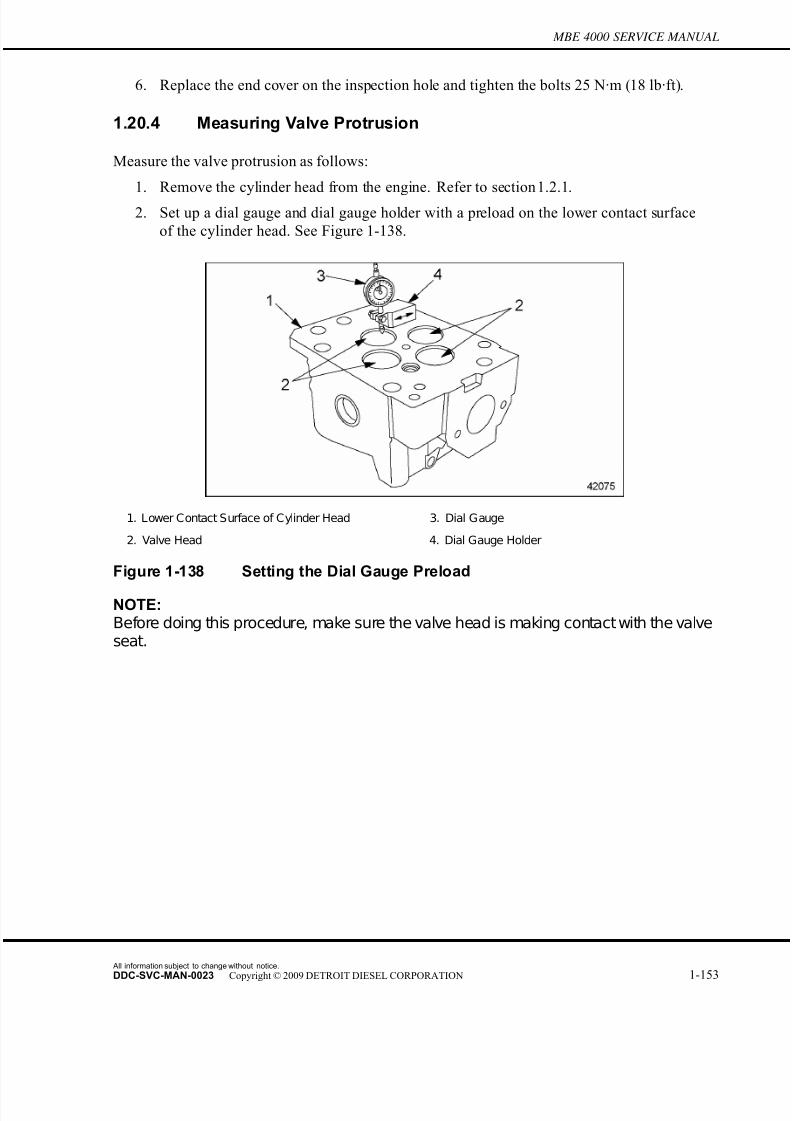
7/22/2019 Manual Mbe 4000 Taller
http://slidepdf.com/reader/full/manual-mbe-4000-taller 197/630
MBE 4000 SERVICE MANUAL
6. Replace the end cover on the inspection hole and tighten the bolts 25 N·m (18 lb·ft).
1.20.4 Measuring Valve Protrusion
Measure the valve protrusion as follows:
1. Remove the cylinder head from the engine. Refer to section 1.2.1.
2. Set up a dial gauge and dial gauge holder with a preload on the lower contact surface
of the cylinder head. See Figure 1-138.
1. Lower Contact Surface of Cylinder Head 3. Dial Gauge
2. Valve Head 4. Dial Gauge Holder
Figure 1-138 Setting the Dial Gauge Preload
NOTE:Before doing this procedure, make sure the valve head is making contact with the valveseat.
All information subject to change without notice.
DDC-SVC-MAN-0023 Copyright © 2009 DETROIT DIESEL CORPORATION 1-153

7/22/2019 Manual Mbe 4000 Taller
http://slidepdf.com/reader/full/manual-mbe-4000-taller 198/630
1.20 VALVES
3. Measure the valve protrusion listed in Table 1-41, from the cylinder head. See Figure
1-139.
NOTE: The valve protrusion is the difference in height between the lower contact surface of thecylinder head and the valve head, when it is touching the valve seat.
1. Cylinder Head 2. Valve Head 3. Valve Stem
Figure 1-139 Measuring Valve Protrusion
Valve Type Description Specification: mm (in.)
Intake Normal 0.7-1.1 (0.03-0.04)
Intake Wear Limit 1.6 (0.06)
Exhaust Normal 0.7-1.1 (0.03-0.04)
Exhaust Wear Limit 1.6 (0.06)
Table 1-41 Valve Protrusion
[a] Set the scale of the dial gauge to "0" (zero).
[b] Move the dial gauge enough so that its probe is touching the valve head.
[c] If the gauge reads between 0.7 and 1.1 mm (0.03 and 0.04 in.), the valve protrusion
is within specifications for new cylinder heads. Skip down to "Install the cylinder
head..."If the gauge reads less than 0.7 mm (0.03 in.), or more than 1.1 mm (0.04
in.), the valve protrusion is not within specifications.
[d] For used heads, if the gauge reads more than 1.6 mm (0.06 in.), inspect valve and
valve seats. Listed in Table 1-44 are the specifications.
4. Install the cylinder head. Refer to section 1.2.2.
All information subject to change without notice.
1-154 DDC-SVC-MAN-0023 Copyright © 2009 DETROIT DIESEL CORPORATION

7/22/2019 Manual Mbe 4000 Taller
http://slidepdf.com/reader/full/manual-mbe-4000-taller 199/630
MBE 4000 SERVICE MANUAL
1.20.5 Valve Removal
Remove the intake and exhaust valves as follows:
NOTE: The MBE 4000 engine has individual heads for each cylinder. To replace the valves
on one head, follow these instructions, step by step. To replace all the valves, repeatthese instructions for all six cylinder heads.
1. Remove the cylinder head from the engine. Refer to section 1.2.1.
2. Using a dial gauge and holder, measure the valve protrusion from the cylinder head.
Refer to section 1.20.4. Listed in Table 1-42 are the normal tolerances and wear limits.
Valve Type Description Specification: mm (in.)
Intake Normal 0.7-1.1 (0.03-0.04)
Intake Wear Limit 1.6 (0.06)
Exhaust Normal 0.7-1.1 (0.03-0.04)
Exhaust Wear Limit 1.6 (0.06)
Table 1-42 Valve Protrusion
NOTE:If the measurement is not within tolerance, machine the valve seat insert, using theprocedures . If the measurement is beyond the wear limit, replace the valve seat insert.
3. Place the cylinder head on wooden blocks.
4. Attach the valve spring adaptor and remover (J–46173), to the cylinder
head. See Figure1-140.
1. Valve 2. Cylinder Head
Figure 1-140 Valve Removal
All information subject to change without notice.
DDC-SVC-MAN-0023 Copyright © 2009 DETROIT DIESEL CORPORATION 1-155
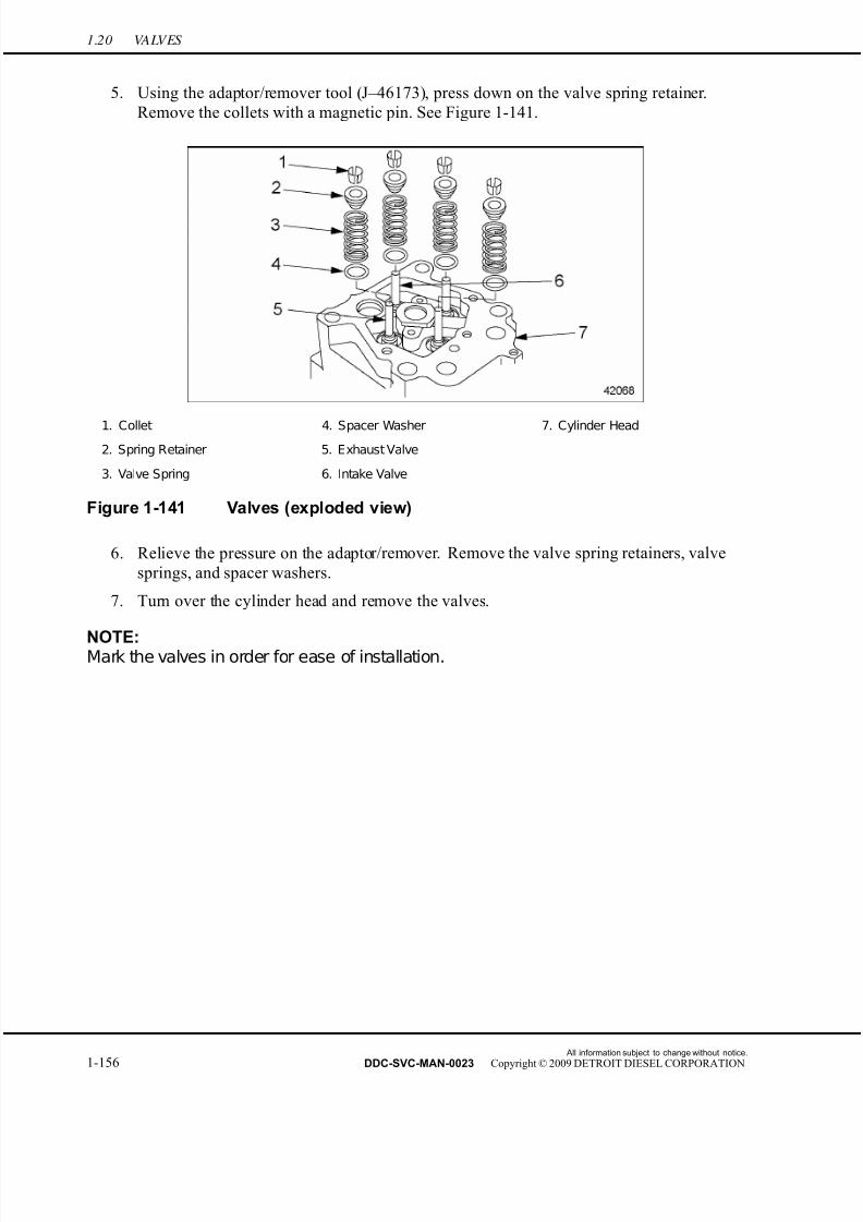
7/22/2019 Manual Mbe 4000 Taller
http://slidepdf.com/reader/full/manual-mbe-4000-taller 200/630
1.20 VALVES
5. Using the adaptor/remover tool (J–46173), press down on the valve spring retainer.
Remove the collets with a magnetic pin. See Figure 1-141.
1. Collet 4. Spacer Washer 7. Cylinder Head
2. Spring Retainer 5. Exhaust Valve
3. Valve Spring 6. Intake Valve
Figure 1-141 Valves (exploded view)
6. Relieve the pressure on the adaptor/remover. Remove the valve spring retainers, valve
springs, and spacer washers.
7. Turn over the cylinder head and remove the valves.
NOTE:Mark the valves in order for ease of installation.
All information subject to change without notice.
1-156 DDC-SVC-MAN-0023 Copyright © 2009 DETROIT DIESEL CORPORATION
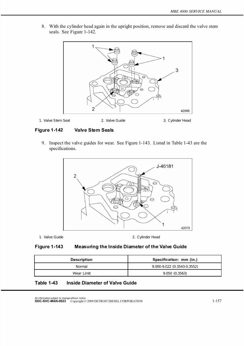
7/22/2019 Manual Mbe 4000 Taller
http://slidepdf.com/reader/full/manual-mbe-4000-taller 201/630
MBE 4000 SERVICE MANUAL
8. With the cylinder head again in the upright position, remove and discard the valve stem
seals. See Figure 1-142.
1. Valve Stem Seal 2. Valve Guide 3. Cylinder Head
Figure 1-142 Valve Stem Seals
9. Inspect the valve guides for wear. See Figure 1-143. Listed in Table 1-43 are the
specifications.
1. Valve Guide 2. Cylinder Head
Figure 1-143 Measuring the Inside Diameter of the Valve Guide
Description Specification: mm (in.)
Normal 9.000-9.022 (0.3543-0.3552)
Wear Limit 9.050 (0.3563)
Table 1-43 Inside Diameter of Valve Guide
All information subject to change without notice.
DDC-SVC-MAN-0023 Copyright © 2009 DETROIT DIESEL CORPORATION 1-157

7/22/2019 Manual Mbe 4000 Taller
http://slidepdf.com/reader/full/manual-mbe-4000-taller 202/630
1.20 VALVES
[a] Measure the inside diameter of the valve guide by inserting the go no/go gauge
(J–46181) into the valve guide.
[b] Replace the valve guide if the larger diameter end of the go no/go gauge tool
(J–46181) fits into either end of the guide.
10. Clean the valves thoroughly. Remove any traces of combustion residue.
11. Check the valves to see if they can be re-used. Replace the valves if the stem ends aredamaged or bent, if the valve grooves are deformed, if the seat is burned, or if the chrome
surface of the shaft is not entirely intact.
12. Check the following critical valve dimensions, and repair as necessary. See Figure 1-144
to determine the dimensions given in the table. Listed in Table 1-44 are the dimensions.
□ Valve stem diameter (A)
□ Valve seat diameter at the contact surface of the cylinder head (B)
□ Valve head diameter (C)
□ Valve seat height (D)
□ Valve seat width at the valve head (E)
□
Valve seat angle (F)□ Valve length (G)
Figure 1-144 Critical Dimensions, Valve Stem and Head
All information subject to change without notice.
1-158 DDC-SVC-MAN-0023 Copyright © 2009 DETROIT DIESEL CORPORATION

7/22/2019 Manual Mbe 4000 Taller
http://slidepdf.com/reader/full/manual-mbe-4000-taller 203/630
MBE 4000 SERVICE MANUAL
Description Intake: mm (in.) Exhaust: mm (in.)
Valve Stem Diameter (A) 8.935-8.950 (0.3518-0.3524) 8.925-8.940 (0.3514-0.3520)
Valve Seat Diameter, at Head
Contact Surface (B)
42.0 (1.65) 39.0 (1.54)
Valve Head Diameter (C) 45.4-45.6 (1.79-1.80) 40.9-41.3 (1.61-1.63)
Valve Seat Height-New (D) 3.1-3.3 (0.12-0.13) 2.8-3.1 (0.11-0.12)
Minimum Valve Seat Height-After
Grinding (D)
2.9 (0.11) 2.3 (0.09)
Valve Seat Width, at Valve Head (E) 3.5-4.5 (0.14-0.18) 3.5-4.5 (0.14-0.18)
Valve Seat Angle (F) 30 degrees 45 degrees
Valve Length (G) 145.0 (5.71) 145.0 (5.71)
Table 1-44 Valve Removal/Installation Specifications in mm (in.)
13. Check the condition of the valve seat insert. Repair the valves if necessary.
14. Inspect the valve springs. Check the springs for correct pressure, using the values
listed in Table 1-45. If damaged, replace the springs.
Description Specification: mm (in.)
Length, Without Load 69.7 (2.74)
Length, Under Load of 382-418 N (86-94 lbf) 49 (1.9)
Length, Under Load of 644-706 N (145-159 lbf) 37 (1.5)
Diameter of Spring Wire 4.2 (0.17)
Outside Diameter of Spring Coil 28.9 (1.14)
Inside Diameter of Spring Coil 24.5-24.9 (0.96-0.98)
Table 1-45 Spring Specifications, Intake and Exhaust Valves
1.20.6 Valve Installation
Install the intake and exhaust valves as follows:
1. Lubricate each valve with a light coating of engine oil.
2. Install the valves in order, as marked on removal.
NOTE:Always replace the valve stem seal if the valve has been removed. Check the seal tomake sure it is correctly seated on the valve guide. Refer to section 1.20.7.
3. Install new valve stem seals. Refer to section 1.20.7.
All information subject to change without notice.
DDC-SVC-MAN-0023 Copyright © 2009 DETROIT DIESEL CORPORATION 1-159

7/22/2019 Manual Mbe 4000 Taller
http://slidepdf.com/reader/full/manual-mbe-4000-taller 204/630
1.20 VALVES
4. Using the adaptor/remover, (J–46173), install the spring bases, springs, spring retainers,
and collets. Check the collets to be sure they are locked in place.
5. Remove the adaptor/remover, (J–46173), from the cylinder head.
6. Install the cylinder head. Refer to section 1.2.2.
1.20.7 Valve Stem Seal Replacement
Replace the valve stem seal as follows:
NOTE:Always replace the valve stem seal if the valve has been removed.
1. Remove the cylinder head from the engine. Refer to section 1.2.1.
NOTE:Use care during removal to not damage the valve guides and valve stems.
2. Remove the collets, spring retainer, valve spring, and spring base. See Figure 1-145.
1. Valve Stem Seal 3. Valve Guide
2. Valve Stem 4. Valve Stem Sealing Ring (installed)
Figure 1-145 Valve Stem Seal Replacement
3. Remove the valve stem seal. Do not remove the valve.4. Lubricate the valve stem and valve stem seal installer/protector (J–46174) with a light
coating of clean engine oil.
NOTE: The installer prevents the groove on the valve stemfromdamaging the seal.
All information subject to change without notice.
1-160 DDC-SVC-MAN-0023 Copyright © 2009 DETROIT DIESEL CORPORATION
7/22/2019 Manual Mbe 4000 Taller
http://slidepdf.com/reader/full/manual-mbe-4000-taller 205/630
MBE 4000 SERVICE MANUAL
5. Push the valve stem seal installer/protector (J–46174) over the valve stem until it makes
contact with the valve.
6. Using valve stem seal installer (J–46184) and the appropriate hammer, drive the valve
stem seal onto the guide.
NOTE:
Check the seal to ensure it is correctly seated on the valve guide.
7. Remove the installer and protector from the valve stem seal and the valve.
8. Install the valve keepers, spring retainer, valve spring and spr ing base, as removed.
9. Repeat the procedure for the other valves.
10. Install the cylinder head. Refer to section 1.2.2.
All information subject to change without notice.
DDC-SVC-MAN-0023 Copyright © 2009 DETROIT DIESEL CORPORATION 1-161
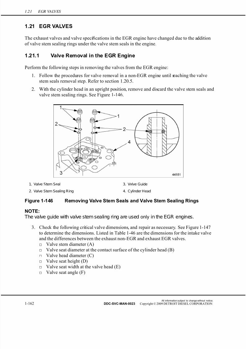
7/22/2019 Manual Mbe 4000 Taller
http://slidepdf.com/reader/full/manual-mbe-4000-taller 206/630
1.21 EGR VALVES
1.21 EGR VALVES
The exhaust valves and valve specifications in the EGR engine have changed due to the addition
of valve stem sealing rings under the valve stem seals in the engine.
1.21.1 Valve Removal in the EGR Engine
Perform the following steps in removing the valves from the EGR engine:
1. Follow the procedures for valve removal in a non-EGR engine until r eaching the valve
stem seals removal step. Refer to section 1.20.5.
2. With the cylinder head in an upright position, remove and discard the valve stem seals and
valve stem sealing rings. See Figure 1-146.
1. Valve Stem Seal 3. Valve Guide
2. Valve Stem Sealing Ring 4. Cylinder Head
Figure 1-146 Removing Valve Stem Seals and Valve Stem Sealing Rings
NOTE: The valve guide with valve stem sealing ring are used only in the EGR engines.
3. Check the following critical valve dimensions, and repair as necessary. See Figure 1-147
to determine the dimensions. Listed in Table 1-46 are the dimensions for the intake valve
and the differences between the exhaust non-EGR and exhaust EGR valves.
□ Valve stem diameter (A)□ Valve seat diameter at the contact surface of the cylinder head (B)
□ Valve head diameter (C)
□ Valve seat height (D)
□ Valve seat width at the valve head (E)
□ Valve seat angle (F)
All information subject to change without notice.
1-162 DDC-SVC-MAN-0023 Copyright © 2009 DETROIT DIESEL CORPORATION

7/22/2019 Manual Mbe 4000 Taller
http://slidepdf.com/reader/full/manual-mbe-4000-taller 207/630
MBE 4000 SERVICE MANUAL
□ Valve length (G)
Figure 1-147 Critical Dimensions, Valve Stem and Head for EGR Engines
Description Intake: mm (in.) Exhaust-EPA 98:
mm (in.)
Exhaust-EPA 04:
mm (in.)
Valve stem diameter (A) 8.935-8.950 (0.3518-
0.3524)
8.925-8.940 (0.3514-
0.3520)
8.925-8.940 (0.3514-
0.3520)
Valve seat diameter at
head contact surface (B)
42.0 (1.65) 39.0 (1.54) 39.0 (1.54)
Valve head diameter (C) 45.4-45.6 (1.79-1.80) 40.9-41.3 (1.61-1.63) 41.9-42.3 (1.65-1.67)
Valve seat height-new (D) 3.1-3.3 (0.12-0.13) 2.8-3.1 (0.11-0.12) 3.0-3.3 (0.12-0.13)
Minimum valve seat
height-after grinding (D)
2.9 (0.11) 2.3 (0.09) 2.9 (0.11)
Valve seat width at valve
head (E)
3.5-4.5 (0.14-0.18) 3.5-4.5 (0.14-0.18) min. 3.5 (0.14)
Valve seat angle (F) 30 degrees 45 degrees 36 degrees
Valve length (G) 145.0 (5.71) 145.0 (5.71) 145.0 (5.71)
Table 1-46 Valve Removal/Installation Specifications in mm (in.) for non-EGRand EGR engines
1.21.2 Valve Installation in the EGR Engine
Perform the following steps in installing the valves in the EGR engine:
1. Install the valve stem sealing ring in the valve guide in the cylinder head.
2. Lubricate each valve with a light coating of engine oil.
All information subject to change without notice.
DDC-SVC-MAN-0023 Copyright © 2009 DETROIT DIESEL CORPORATION 1-163

7/22/2019 Manual Mbe 4000 Taller
http://slidepdf.com/reader/full/manual-mbe-4000-taller 208/630
1.21 EGR VALVES
3. Install the valves in order, as marked on removal.
NOTE:In the EGR engine, always replace the valve stem seal and valve stem sealing ring if the valve has been removed. Check the valve stem seal to make sure it is correctlyseated on the valve guide.
4. Using valve stem seal installer/protector (J–46174), install new valve stem seals and seat
the valve stem seal with valve stem seal installer (J–46184). Refer to section 1.21.3.
5. Using the adaptor (J–46173), install the spring seats, springs, s pring retainers, and collets
(keepers). Check the keepers to be sure they are locked in place.
6. Remove the adaptor (J–46173), from the cylinder head.
7. Install the cylinder head.
1.21.3 Valve Stem Seal and Valve Stem Sealing Ring Replacement inthe EGR Engine
Replace the valve stem seal and valve stem sealing ring as follows:
NOTE:In the EGR engine, always replace the valve stem seal and valve stem sealing ringif the valve has been removed.
1. Remove the cylinder head from the engine.
NOTE:Use care during removal to not damage the valve guides and valve stems.
2. Remove the keeper, spring retainer, valve spring, and spring seat.
3. Remove the valve stem seal and discard.
4. Remove the valve.
5. Remove the valve stem sealing ring and discard. Repeat procedure for all remaining
valves.
6. Clean all parts before reinstalling components.
7. Install the valve stem sealing ring in the valve guide and then install the valve in the head.
Repeat procedure for all remaining valves.
All information subject to change without notice.
1-164 DDC-SVC-MAN-0023 Copyright © 2009 DETROIT DIESEL CORPORATION
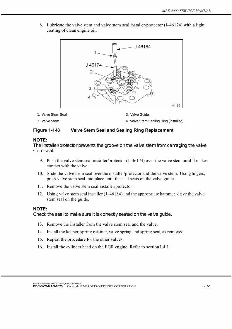
7/22/2019 Manual Mbe 4000 Taller
http://slidepdf.com/reader/full/manual-mbe-4000-taller 209/630
MBE 4000 SERVICE MANUAL
8. Lubricate the valve stem and valve stem seal installer/protector (J–46174) with a light
coating of clean engine oil.
1. Valve Stem Seal 3. Valve Guide
2. Valve Stem 4. Valve Stem Sealing Ring (installed)
Figure 1-148 Valve Stem Seal and Sealing Ring Replacement
NOTE: The installer/protector prevents the groove on the valve stemfrom damaging the valvestem seal.
9. Push the valve stem seal installer/protector (J–46174) over the valve stem until it makes
contact with the valve.
10. Slide the valve stem seal over the installer/protector and the valve stem. Using fingers, press valve stem seal into place until the seal seats on the valve guide.
11. Remove the valve stem seal installer/protector.
12. Using valve stem seal installer (J–46184) and the appropriate hammer, drive the valve
stem seal on the guide.
NOTE:Check the seal to make sure it is correctly seated on the valve guide.
13. Remove the installer from the valve stem seal and the valve.
14. Install the keeper, spring retainer, valve spring and spring seat, as removed.
15. Repeat the procedure for the other valves.
16. Install the cylinder head on the EGR engine. Refer to section 1.4.1.
All information subject to change without notice.
DDC-SVC-MAN-0023 Copyright © 2009 DETROIT DIESEL CORPORATION 1-165
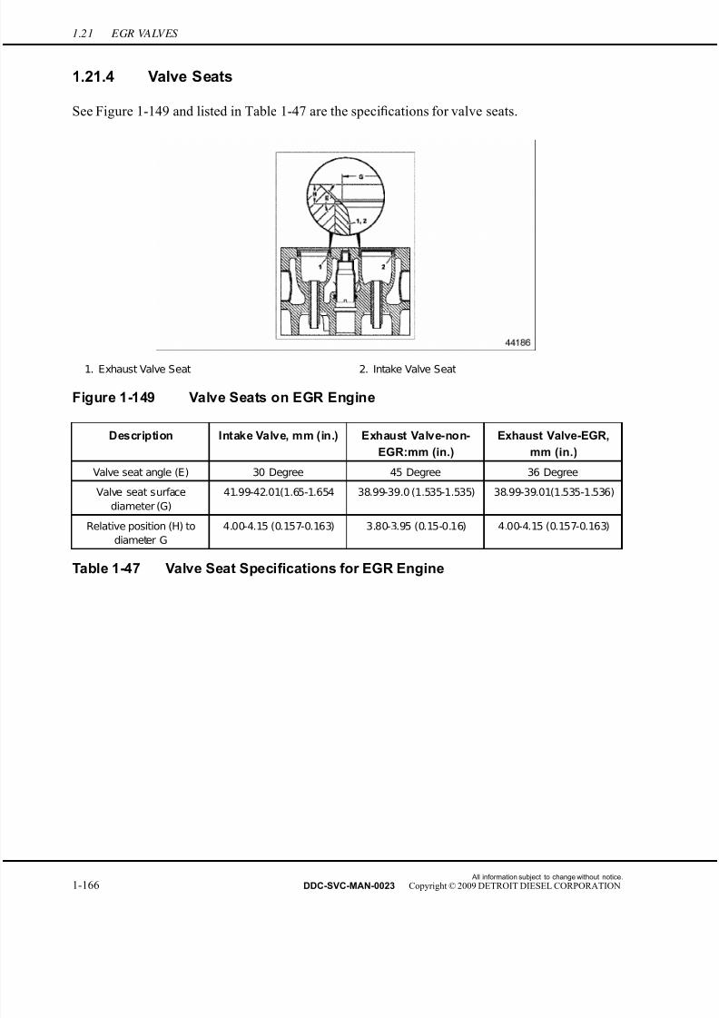
7/22/2019 Manual Mbe 4000 Taller
http://slidepdf.com/reader/full/manual-mbe-4000-taller 210/630
1.21 EGR VALVES
1.21.4 Valve Seats
See Figure 1-149 and listed in Table 1-47 are the specifications for valve seats.
1. Exhaust Valve Seat 2. Intake Valve Seat
Figure 1-149 Valve Seats on EGR Engine
Description Intake Valve, mm (in.) Exhaust Valve-non-
EGR:mm (in.)
Exhaust Valve-EGR,
mm (in.)
Valve seat angle (E) 30 Degree 45 Degree 36 Degree
Valve seat surface
diameter (G)
41.99-42.01(1.65-1.654 38.99-39.0 (1.535-1.535) 38.99-39.01(1.535-1.536)
Relative position (H) to
diameter G
4.00-4.15 (0.157-0.163) 3.80-3.95 (0.15-0.16) 4.00-4.15 (0.157-0.163)
Table 1-47 Valve Seat Specifications for EGR Engine
All information subject to change without notice.
1-166 DDC-SVC-MAN-0023 Copyright © 2009 DETROIT DIESEL CORPORATION
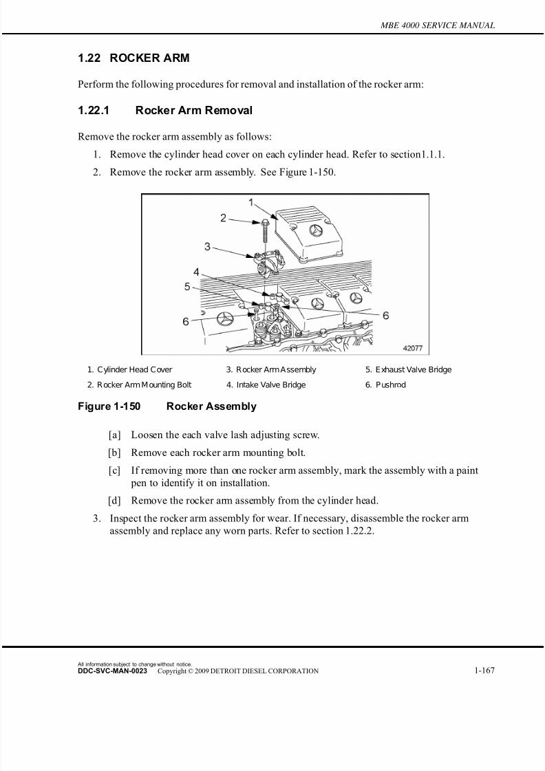
7/22/2019 Manual Mbe 4000 Taller
http://slidepdf.com/reader/full/manual-mbe-4000-taller 211/630
MBE 4000 SERVICE MANUAL
1.22 ROCKER ARM
Perform the following procedures for removal and installation of the rocker arm:
1.22.1 Rocker Arm Removal
Remove the rocker arm assembly as follows:
1. Remove the cylinder head cover on each cylinder head. Refer to section 1.1.1.
2. Remove the rocker arm assembly. See Figure 1-150.
1. Cylinder Head Cover 3. Rocker ArmAssembly 5. Exhaust Valve Bridge
2. R ocker Arm M ounting Bolt 4. Intake Valve Bridge 6. P ushrod
Figure 1-150 Rocker Assembly
[a] Loosen the each valve lash adjusting screw.
[b] Remove each rocker arm mounting bolt.
[c] If removing more than one rocker arm assembly, mark the assembly with a paint
pen to identify it on installation.
[d] Remove the rocker arm assembly from the cylinder head.
3. Inspect the rocker arm assembly for wear. If necessary, disassemble the rocker arm
assembly and replace any worn parts. Refer to section 1.22.2.
All information subject to change without notice.
DDC-SVC-MAN-0023 Copyright © 2009 DETROIT DIESEL CORPORATION 1-167

7/22/2019 Manual Mbe 4000 Taller
http://slidepdf.com/reader/full/manual-mbe-4000-taller 212/630
1.22 ROCKER ARM
4. Measure each rocker arm mounting bolt. Replace each bolt longer than 91 mm (3.6 in.), as
listed in Table 1-48.
Size Max. Shaft Length: mm (in.) Torque Value: N·m (lb·ft)
M12 91 (3.6)60 (44)
then an additional 90°
Table 1-48 Specifications, Rocker Arm Mounting Bolts
5. Remove the valve bridge from each set of valves, intake and exhaust.
6. Inspect the valve bridges for wear. If necessary, re place any worn valve bridge(s).
1.22.2 Rocker Arm Disassembly
Disassemble the rocker arm unit as follows:
1. Remove the rocker arm assembly from the cylinder head. Refer to section 1.22.1.
2. Remove the snap rings from each end of the r ocker arm shaft. See Figure 1-151.
1. Snap Ring 4. Rocker Support 7. Adjusting Screw
2. Washer 5. Intake Rocker Arm
3. Exhaust R ocker Arm 6. Locknut
Figure 1-151 Rocker Arm Components
3. Remove the rocker arms and washers from the shafts on each end of the rocker arm
support. Keep all parts in order, as removed, for ease of assembly.
[a] Remove the intake rocker arm and washer.
[b] Remove the exhaust rocker arm and washer.
[c] Remove the adjusting screw and locknut from both intake and exhaust rocker arms.
All information subject to change without notice.
1-168 DDC-SVC-MAN-0023 Copyright © 2009 DETROIT DIESEL CORPORATION

7/22/2019 Manual Mbe 4000 Taller
http://slidepdf.com/reader/full/manual-mbe-4000-taller 213/630
MBE 4000 SERVICE MANUAL
[d] Mark each rocker arm and shaft with paint pens, for ease of installation.
4. Inspect the parts of the rocker arm assembly for wear, and replace if necessary.
1.22.3 Rocker Arm Assembly
Assemble the rocker arm unit as follows:
1. Install the adjusting screw and locknut on both intake and exhaust rocker arms. Tighten
the locknut 50 N·m (37 lb·ft).
2. Inspect the inside diameter of the rocker arm bushing. Replace the rocker arm bushing
if the inside diameter is smaller than 25.005 mm (0.9844 in.) or larger than 25.021 mm
(0.9851 in.) as listed in Table 1-49.
Description Specification: mm (in.)
Bushing Inside Diameter (when installed) 25.005-25.021 (0.9844-0.9851)
Shaft Diameter 24.967-24.980 (0.9830-0.9835)
Table 1-49 Rocker Arm Bushing Specifications
3. Inspect the diameter of the rocker ar m shaft. Replace the rocker arm shaft if the diameter
is smaller than 24.967 mm (0.9830 in.) or larger than 24.980 mm (0.9835 in.).
4. Lubricate the washers, rocker arm bushings, and the shafts of the support with a light
coating of engine oil.
5. Install the rocker arms and washers on the correct rocker arm shaft, as marked on removal.
Make sure both intake and exhaust rocker arms are installed correctly.
6. When the assembly is com plete, secure the assembly by installing a snap ring on the endof each rocker arm shaft.
1.22.4 Rocker Arm Installation
Install the rocker arm unit as follows:
1. Install a valve br idge on each set of valves, both intake and exhaust.
2. Lubricate each pushrod with a light coating of engine oil.
All information subject to change without notice.
DDC-SVC-MAN-0023 Copyright © 2009 DETROIT DIESEL CORPORATION 1-169

7/22/2019 Manual Mbe 4000 Taller
http://slidepdf.com/reader/full/manual-mbe-4000-taller 214/630
1.22 ROCKER ARM
3. Inspect each pushrod to be sure it is correctly seated in its tappet. Replace any pushrods
that are warped, are not correctly seated, or are not the correct length as listed in Table
1-50.
Description Stage Specification: mm (in.)
Outside Diameter of Valve Tappets Normal 29.931-29.952 (1.1784-1.1792)
Outside Diameter of Valve Tappets Repair Stage I 30.444-30.465 (1.1986-1.1994)
Diameter of Tappet Seats (in
cylinder block)Normal 30.000-30.021 (1.1811-1.1819)
Diameter of Tappet Seats (in
cylinder block)Repair Stage I 30.500-30.525 (1.2008-1.2018)
Total Length of Pushrods 345.0-346.5 (13.58-13.64)
Maximum Pushrod Warpage 0.5 (0.02)
Maximum Length of Rocker Arm Mounting Bolts 91 (3.6)
Table 1-50 Rocker Arm Specifications
4. Install the rocker arm assembly.
[a] Position the rocker arm assembly on the cylinder head, as removed.
[b] Install the mounting bolts in the holes in the cylinder head.
[c] Tighten each mounting bolt 60 N·m (44 lb·ft). Final angular tightening: 90 degrees.
5. Adjust the valve lash. Refer to section 1.20.3.
6. Install the cylinder head cover on each cylinder head. Refer to section 1.1.2.
All information subject to change without notice.
1-170 DDC-SVC-MAN-0023 Copyright © 2009 DETROIT DIESEL CORPORATION

7/22/2019 Manual Mbe 4000 Taller
http://slidepdf.com/reader/full/manual-mbe-4000-taller 215/630
MBE 4000 SERVICE MANUAL
1.23 CAMSHAFT AND CAMSHAFT POSITION SENSOR
The camshaft is made of induction-hardened steel and has seven main bearings. Each cylinder has
cams for intake and exhaust valves and a unit pump.
1.23.1 Camshaft Removal
Remove the camshaft as follows:
NOTE:Before removing the camshaft, clean the engine to prevent road dirt, grease, or otherforeign matter from contaminating the exposed gears and other engine parts.
1. Drain the engine oil.
FALLING ENGINE
To avoid injury from a falling engine, an adequate liftingdevice with a spreader bar and sling should be used to liftthe engine. The sling and spreader bar should be adjustedso the lifting hooks are vertical to prevent bending the lifter brackets. To ensure proper weight distribution, all providedlifter brackets must be used.
NOTICE:
A spreader bar must be used at all times in conjunction with thefront and rear lifter brackets to liftthe EGR engine to ensure thatno engine damage will result. The brackets are designed to liftvertically.
2. Remove the engine from the vehicle.
FALLING ENGINE
To avoid injury from a falling engine, ensure the engineis securely attached to the engine overhaul stand beforereleasing the lifting sling.
3. Install the engine on an engine stand.
4. Remove the electronic unit pumps (EUP).
5. Remove the vibration damper. Refer to section 1.12.1.
All information subject to change without notice.
DDC-SVC-MAN-0023 Copyright © 2009 DETROIT DIESEL CORPORATION 1-171

7/22/2019 Manual Mbe 4000 Taller
http://slidepdf.com/reader/full/manual-mbe-4000-taller 216/630
1.23 CAMSHAFT AND CAMSHAFT POSITION SENSOR
6. Remove the fan support.
7. Remove the eight mounting bolts attaching the camshaft front cover to the cylinder block.
See Figure 1-152.
Figure 1-152 Removing the Camshaft Front Cover
8. Remove the fuel pump drive gear from the front of the camshaft. See Figure 1-153.
1. Drive Gear Mounting Bolt 3. Cover Mounting Bolt 5. Front of Camshaft
2. F ront C amshaft C over 4. F uel P ump Drive Gear 6. F uel P ump Driven Gear
Figure 1-153 Camshaft Assembly
All information subject to change without notice.
1-172 DDC-SVC-MAN-0023 Copyright © 2009 DETROIT DIESEL CORPORATION

7/22/2019 Manual Mbe 4000 Taller
http://slidepdf.com/reader/full/manual-mbe-4000-taller 217/630
MBE 4000 SERVICE MANUAL
9. Remove the rocker arm assembly and pushrods. Refer to section 1.22.1.
10. Turn the engine on the stand until it is upside down.
11. Remove the oil pan.
12. Remove the flywheel housing. Refer to section 1.17.1.
NOTICE:Do not damage the camshaft bearings in the crankcase. If thecamshaft bearings are damaged, the crankcase will have to bereplaced.
13. Attach the camshaft guide tool (J-46183) to the f ront of the camshaft. See Figure 1-154.
1. Front of Camshaft
Figure 1-154 Attaching the Camshaft Guide Tool
14. From the gear end (rear of the engine), carefully remove the camshaft from the block.
See Figure 1-154.
All information subject to change without notice.
DDC-SVC-MAN-0023 Copyright © 2009 DETROIT DIESEL CORPORATION 1-173

7/22/2019 Manual Mbe 4000 Taller
http://slidepdf.com/reader/full/manual-mbe-4000-taller 218/630
1.23 CAMSHAFT AND CAMSHAFT POSITION SENSOR
15. Pull the tappets (valve lifters) out of the block. Mark the tappets, in order, as removed.
See Figure 1-155.
1. Cylinder Block 3. Tappet (valve lifter)
2. Camshaft Entry Hole 4. Fuel Pump Driven Gear
Figure 1-155 Removing the Tappets
16. Clean and inspect the tappets. Replace the tappets if there are signs of damage or wear, or
if any of the measurements do not meet the specifications listed in Table 1-51.
Description Repair Stage Specifications: mm (in.)
Tappet Outside Diameter Standard 29.931-29.952 (1.1784-1.1792)
Tappet Outside Diameter Repair Stage I 30.444-30.465 (1.1986-1.1994)
Tappet Housing Diameter (in
cylinder block)Standard 30.000-30.021 (1.1811-1.1819)
Tappet Housing Diameter (in
cylinder block)Repair Stage I 30.500-30.525 (1.2008-1.2018)
Table 1-51 Valve Tappet Specifications
[a] Measure the outside diameter of each tappet.
[b] Measure the diameter of the tappet housing in the cylinder block.
17. Inspect the camshaft. Refer to section 1.23.1.1.
All information subject to change without notice.
1-174 DDC-SVC-MAN-0023 Copyright © 2009 DETROIT DIESEL CORPORATION
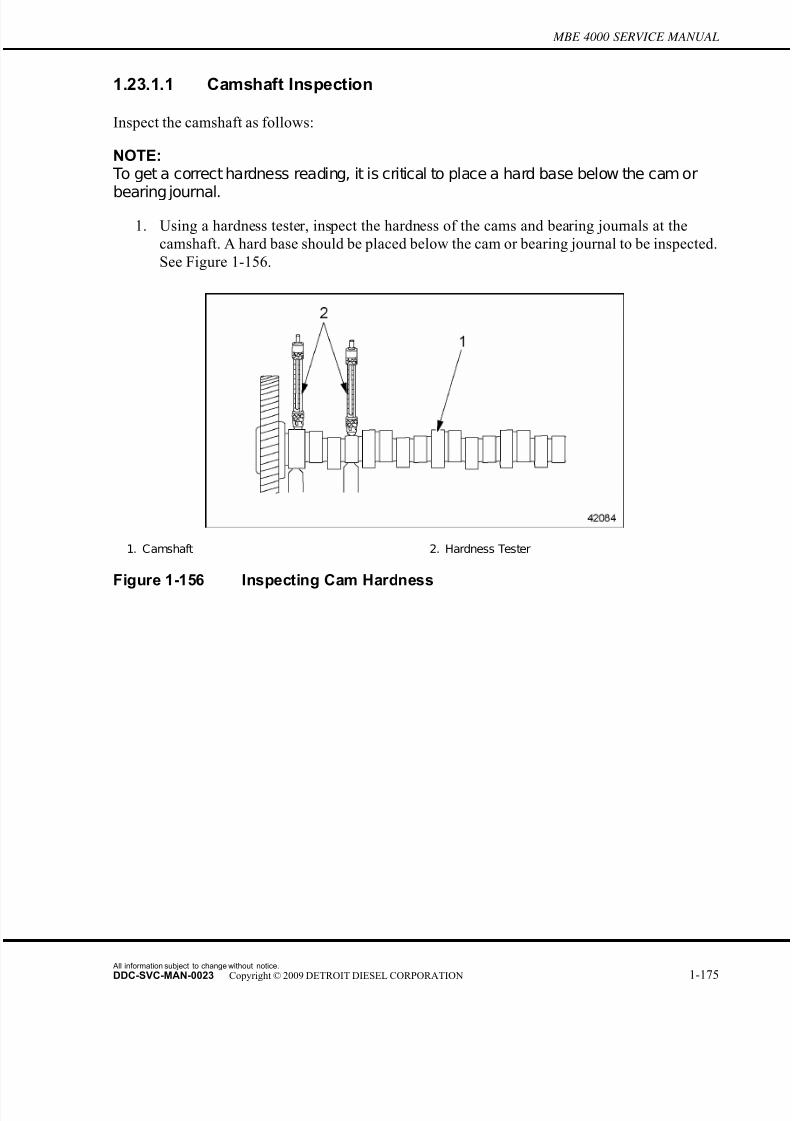
7/22/2019 Manual Mbe 4000 Taller
http://slidepdf.com/reader/full/manual-mbe-4000-taller 219/630
MBE 4000 SERVICE MANUAL
1.23.1.1 Camshaft Inspection
Inspect the camshaft as follows:
NOTE: To get a correct hardness reading, it is critical to place a hard base below the cam or
bearing journal.
1. Using a hardness tester, inspect the hardness of the cams and bearing journals at the
camshaft. A hard base should be placed below the cam or bearing journal to be inspected.
See Figure 1-156.
1. Camshaft 2. Hardness Tester
Figure 1-156 Inspecting Cam Hardness
All information subject to change without notice.
DDC-SVC-MAN-0023 Copyright © 2009 DETROIT DIESEL CORPORATION 1-175
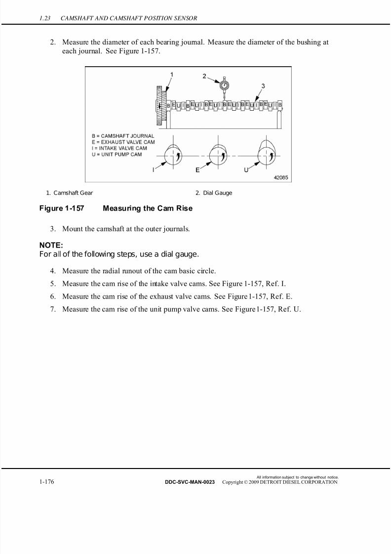
7/22/2019 Manual Mbe 4000 Taller
http://slidepdf.com/reader/full/manual-mbe-4000-taller 220/630
1.23 CAMSHAFT AND CAMSHAFT POSITION SENSOR
2. Measure the diameter of each bearing journal. Measure the diameter of the bushing at
each journal. See Figure 1-157.
1. Camshaft Gear 2. Dial Gauge
Figure 1-157 Measuring the Cam Rise
3. Mount the camshaft at the outer journals.
NOTE:For all of the following steps, use a dial gauge.
4. Measure the radial runout of the cam basic circle.
5. Measure the cam rise of the intake valve cams. See Figure 1-157, Ref. I.
6. Measure the cam rise of the exhaust valve cams. See Figure 1-157, Ref. E.
7. Measure the cam rise of the unit pump valve cams. See Figure 1-157, Ref. U.
All information subject to change without notice.
1-176 DDC-SVC-MAN-0023 Copyright © 2009 DETROIT DIESEL CORPORATION

7/22/2019 Manual Mbe 4000 Taller
http://slidepdf.com/reader/full/manual-mbe-4000-taller 221/630
MBE 4000 SERVICE MANUAL
8. Replace the camshaft if any of the measurements do not meet the specifications
listed in Table 1-52.
What To Measure Where To Measure Value: mm (in.) Unless
otherwise noted
Hardness of Surface At Cams and J ournals 57–63 HRC
Camshaft Radial Runout When
Mounted on Outer Bearing J ournalsAt Gear Seat 0.020 (0.0008)
Camshaft Radial Runout When
Mounted on Outer Bearing J ournalsAt Cam Circle 0.025 (0.0010)
Camshaft Radial Runout When
Mounted on Outer Bearing J ournalsAt C amshaft J ournals 0.030 (0.0012)
Minimum Valve Cam Rise–Above
Basic CircleIntake Valve 7.3 (0.29)
Minimum Valve Cam Rise–Above
Basic CircleExhaust Valve 8.2 (0.32)
Camshaft J ournal Diameter For New Camshaft 81.893–81.928 (3.2241–3.2255)
Bushing Diameter At Camshaft J ournals 82.000–82.035 (3.2283–3.2297)
Gear Back Lash Cam Gear to Crank Gear 0.074–0.176 (0.0029–0.0069)
Gear Back Lash Cam Gear to Air Compressor Gear 0.082–0.168 (0.0032–0.0066)
Table 1-52 Camshaft Specifications
1.23.2 Camshaft Installation
Install the camshaft as follows:
1. Lubricate the tappets with a light coating of clean engine oil.
2. Install the tappets in the block, in order, as removed.
NOTICE:
Do not damage the camshaft bearings in the crankcase. If thecamshaft bearings are damaged, the crankcase will have to bereplaced.
3. Install the camshaft.
[a] Lubricate the cams and camshaft journals with a light coating of clean engine oil.[b] Attach the camshaft guide tool (J-46183) to the camshaft.
All information subject to change without notice.
DDC-SVC-MAN-0023 Copyright © 2009 DETROIT DIESEL CORPORATION 1-177

7/22/2019 Manual Mbe 4000 Taller
http://slidepdf.com/reader/full/manual-mbe-4000-taller 222/630
1.23 CAMSHAFT AND CAMSHAFT POSITION SENSOR
[c] Rotate the camshaft until the marked gear teeth on the camshaft gear are aligned with
the marked tooth on the crankshaft gear. See Figure 1-158.
1. Camshaft Gear 2. Crankshaft Gear 3. Dowel Pin
Figure 1-158 Aligning the Marked Gear Teeth
[d] Carefully insert the camshaft into the block.
4. Install the flywheel housing. Ref er to section 1.17.2.
5. Install the oil pan.
6. Install the fuel pump drive gear on the front of the camshaft, as removed. Torque the
bolts to 60 N·m (44 lb·ft.)
7. Turn the engine on the stand until it is right side up.8. Install the unit pumps.
9. Install the camshaft f ront cover on the cylinder block, as removed. Torque the mounting
bolts to 50 N·m (37 lb·ft.)
10. Install the fan support.
11. Install the vibration damper. Refer to section 1.12.2.
12. Lubricate the pushrods with a light coating of clean engine oil. Install the pushrods and
the rocker arm assembly. Refer to section 1.22.4.
All information subject to change without notice.
1-178 DDC-SVC-MAN-0023 Copyright © 2009 DETROIT DIESEL CORPORATION
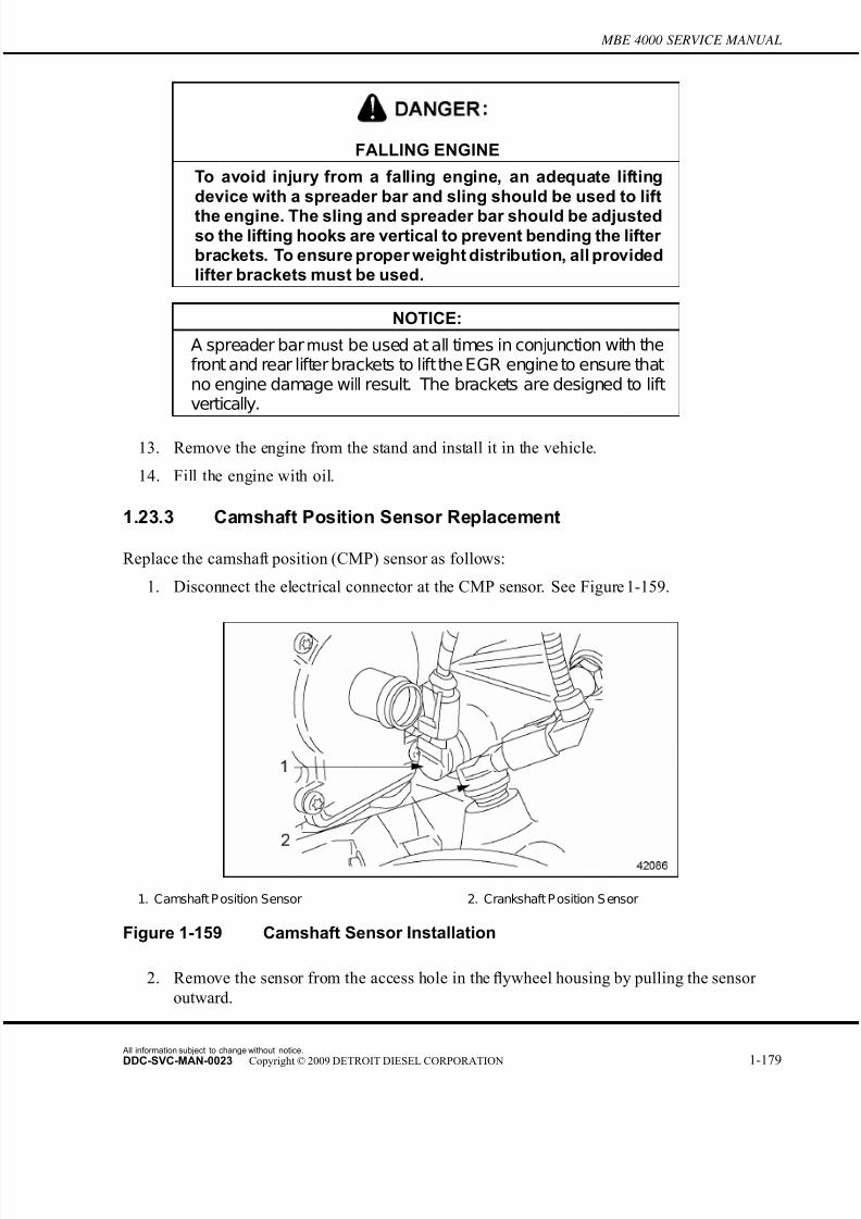
7/22/2019 Manual Mbe 4000 Taller
http://slidepdf.com/reader/full/manual-mbe-4000-taller 223/630
MBE 4000 SERVICE MANUAL
FALLING ENGINE
To avoid injury from a falling engine, an adequate liftingdevice with a spreader bar and sling should be used to lift
the engine. The sling and spreader bar should be adjustedso the lifting hooks are vertical to prevent bending the lifter brackets. To ensure proper weight distribution, all providedlifter brackets must be used.
NOTICE:
A spreader bar must be used at all times in conjunction with thefront and rear lifter brackets to liftthe EGR engine to ensure thatno engine damage will result. The brackets are designed to liftvertically.
13. Remove the engine from the stand and install it in the vehicle.
14. Fill the engine with oil.
1.23.3 Camshaft Position Sensor Replacement
Replace the camshaft position (CMP) sensor as follows:
1. Disconnect the electrical connector at the CMP sensor. See Figure 1-159.
1. Camshaft P osition Sensor 2. Crankshaft P osition S ensor
Figure 1-159 Camshaft Sensor Installation
2. Remove the sensor from the access hole in the flywheel housing by pulling the sensor
outward.
All information subject to change without notice.
DDC-SVC-MAN-0023 Copyright © 2009 DETROIT DIESEL CORPORATION 1-179

7/22/2019 Manual Mbe 4000 Taller
http://slidepdf.com/reader/full/manual-mbe-4000-taller 224/630
1.23 CAMSHAFT AND CAMSHAFT POSITION SENSOR
3. Install a new sensor in the flywheel housing by pushing in the sensor into the access
hole until it bottoms.
4. Connect the electrical connector to the CMP sensor.
NOTE:Be sure that the correct electrical connector is connected to the sensor.
All information subject to change without notice.
1-180 DDC-SVC-MAN-0023 Copyright © 2009 DETROIT DIESEL CORPORATION

7/22/2019 Manual Mbe 4000 Taller
http://slidepdf.com/reader/full/manual-mbe-4000-taller 225/630
MBE 4000 SERVICE MANUAL
1.24 EGR CAMSHAFT
The removal, installation, and inspection of the EGR camshaft is the same as in the
non-EGR engine, except for the following minor changes.
1.24.1 EGR Camshaft Changes
In the EGR engine, there is a possibility of installing the camshaft bushings in an inverted
(wrong) position.
NOTICE:
If theEGR camshaftbushings are installed inaninverted(wrong)channel position, thereis potentialforenginedamage due to lackof lubrication. The holes in the camshaft journal must be linedup with the holes in the camshaft bushing.
1. Bushing Groove
Figure 1-160 Camshaft Bushing Installation
All information subject to change without notice.
DDC-SVC-MAN-0023 Copyright © 2009 DETROIT DIESEL CORPORATION 1-181

7/22/2019 Manual Mbe 4000 Taller
http://slidepdf.com/reader/full/manual-mbe-4000-taller 226/630
1.24 EGR CAMSHAFT
All information subject to change without notice.
1-182 DDC-SVC-MAN-0023 Copyright © 2009 DETROIT DIESEL CORPORATION
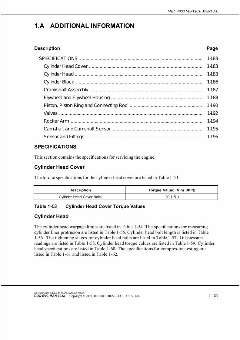
7/22/2019 Manual Mbe 4000 Taller
http://slidepdf.com/reader/full/manual-mbe-4000-taller 227/630
MBE 4000 SERVICE MANUAL
1.A ADDITIONAL INFORMATION
Description Page
SP ECIFICATIONS ............................................................................................. 1-183Cylinder Head Cover ...................................................................................... 1-183
Cylinder Head ................................................................................................. 1-183
Cylinder Block ................................................................................................ 1-186
Crankshaft Assembly ..................................................................................... 1-187
Flywheel and Flywheel Housing ..................................................................... 1-188
Piston, Piston Ring and Connecting Rod ....................................................... 1-190
Valves ............................................................................................................. 1-192
Rocker Arm .................................................................................................... 1-194
Camshaft and Camshaft Sensor .................................................................... 1-195
Sensor and Fittings ........................................................................................ 1-196
SPECIFICATIONS
This section contains the specifications for servicing the engine.
Cylinder Head Cover
The torque specifications for the cylinder head cover are listed in Table 1-53.
Description Torque Value: N·m (lb·ft)
Cylinder Head Cover Bolts 20 (15 )
Table 1-53 Cylinder Head Cover Torque Values
Cylinder Head
The cylinder head warpage limits are listed in Table 1-54. The specifications for measuring
cylinder liner protrusion are listed in Table 1-55. Cylinder head bolt length is listed in Table
1-56. The tightening stages for cylinder head bolts are listed in Table 1-57. Oil pressurereadings are listed in Table 1-58. Cylinder head torque values are listed in Table 1-59. Cylinder
head specifications are listed in Table 1-60. The specifications for compression testing are
listed in Table 1-61 and listed in Table 1-62.
All information subject to change without notice.
DDC-SVC-MAN-0023 Copyright © 2009 DETROIT DIESEL CORPORATION 1-183

7/22/2019 Manual Mbe 4000 Taller
http://slidepdf.com/reader/full/manual-mbe-4000-taller 228/630
Description Limit: mm (in.)
Over a length of 150 mm (6 in.) 0.015 (0.0006)
Table 1-54 Head Warpage Limits
Description Value: mm (in.)
Cylinder Liner Protrusion from block 0.2305-0.330 (0.0090-0.0130)
Difference between the four measuring points Max.: 0.02 (0.0007)
Table 1-55 Specifications for Measuring Cylinder Liner Protrusion
Description Length: mm (in.)
Shaft length when new 210.0 (8.27)
Maximum shaft length 212.0 (8.35)
Table 1-56 Cylinder Head Bolt Lengths
Size Max. Shaft Length:
mm (in.)
Tightening Stage Torque Value: N·m
(lb·ft)
Stage 1 10 (7)
Stage 2 50 (37)
Stage 3 100 (74)
Stage 4 200 (148)
Stage 5 additional 90°
M15 x 2 212.0 (8.35)
Stage 6 additional 90°
Table 1-57 Tightening Stages, Cylinder Head Bolts
Description Minimum Oil Pressure Reading: kPa (psi)
Engine at Idle Speed 50 (7)
Engine at Max. rpm 250 (36)
Table 1-58 Oil Pressure Readings
Descr iption Torque Value: N·m (lb·ft)
Exhaust Manifold Bolts 50 N·m (37 lb·ft)
High-Pressure Fuel Lines 25 N·m (18 lb·ft)
Inspection Cover on F lywheel Housing 25 N·m (18 lb·ft)
Rocker Arm Mounting Bolts 60 N·m (44 lb·ft); then another 90°
Table 1-59 Cylinder Head Torque Values
All information subject to change without notice.
1-184 DDC-SVC-MAN-0023 Copyright © 2009 DETROIT DIESEL CORPORATION
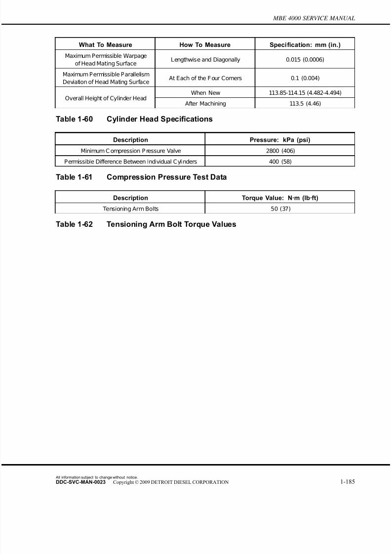
7/22/2019 Manual Mbe 4000 Taller
http://slidepdf.com/reader/full/manual-mbe-4000-taller 229/630
MBE 4000 SERVICE MANUAL
What To Measure How To Measure Specification: mm (in.)
Maximum Permissible Warpage
of Head Mating SurfaceLengthwise and Diagonally 0.015 (0.0006)
Maximum Permissible Parallelism
Deviation of Head Mating SurfaceAt Each of the F our Corners 0.1 (0.004)
When New 113.85-114.15 (4.482-4.494)Overall Height of Cylinder Head
After Machining 113.5 (4.46)
Table 1-60 Cylinder Head Specifications
Description Pressure: kPa (psi)
Minimum C ompression P ressure Valve 2800 (406)
Permissible Difference Between Individual Cylinders 400 (58)
Table 1-61 Compression Pressure Test Data
Description Torque Value: N·m (lb·ft)
Tensioning Arm Bolts 50 (37)
Table 1-62 Tensioning Arm Bolt Torque Values
All information subject to change without notice.
DDC-SVC-MAN-0023 Copyright © 2009 DETROIT DIESEL CORPORATION 1-185
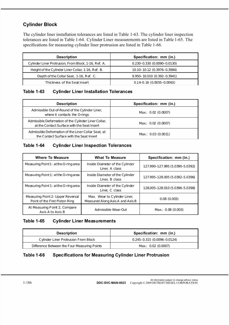
7/22/2019 Manual Mbe 4000 Taller
http://slidepdf.com/reader/full/manual-mbe-4000-taller 230/630
Cylinder Block
The cylinder liner installation tolerances are listed in Table 1-63. The cylinder liner inspection
tolerances are listed in Table 1-64. Cylinder Liner measurements are listed in Table 1-65. The
specifications for measuring cylinder liner protrusion are listed in Table 1-66.
Description Specification: mm (in.)
Cylinder Liner Protrusion, From Block, 1-16, Ref. A. 0.230–0.330 (0.0090–0.0130)
Height of the Cylinder Liner Collar, 1-16, Ref. B. 10.10–10.12 (0.3976–0.3984)
Depth of the Collar Seat, 1-16, R ef. C. 9.950– 10.010 (0.392– 0.3941)
Thickness of the Seat Insert 0.14–0.16 (0.0055–0.0063)
Table 1-63 Cylinder Liner Installation Tolerances
Description Specification: mm (in.)
Admissible Out-of-Round of the Cylinder Liner,
where it contacts the O-rings Max.: 0.02 (0.0007)
Admissible Deformation of the Cylinder Liner Collar,
at the Contact Surface with the Seat InsertMax.: 0.02 (0.0007)
Admissible Deformation of the Liner Collar Seat, at
the Contact Surface with the Seat InsertMax.: 0.03 (0.0011)
Table 1-64 Cylinder Liner Inspection Tolerances
Where To Measure What To Measure Specification: mm (in.)
Measuring Point1: atthe O-ring area Inside Diameter of the Cylinder
Liner, A class127.990–127.995 (5.0390–5.0392)
Measuring Point1: atthe O-ringarea Inside Diameter of the Cylinder
Liner, B class127.995–128.005 (5.0392–5.0396)
Measuring Point1: atthe O-ringarea Inside Diameter of the Cylinder
Liner, C class128.005–128.010 (5.0396–5.0398)
Measuring Point 2: Upper Reversal
Point of the First Piston Ring
Max. Wear to Cylinder Liner,
Measured Along Axis A and Axis B0.08 (0.003)
At Measuring P oint 2, Compare
Axis A to Axis BAdmissible Wear-Out Max.: 0.08 (0.003)
Table 1-65 Cylinder Liner Measurements
Description Specification: mm (in.)
Cylinder Liner Protrusion From Block 0.245–0.315 (0.0096–0.0124)
Difference Between the Four Measuring Points Max.: 0.02 (0.0007)
Table 1-66 Specifications for Measuring Cylinder Liner Protrusion
All information subject to change without notice.
1-186 DDC-SVC-MAN-0023 Copyright © 2009 DETROIT DIESEL CORPORATION

7/22/2019 Manual Mbe 4000 Taller
http://slidepdf.com/reader/full/manual-mbe-4000-taller 231/630
MBE 4000 SERVICE MANUAL
Crankshaft Assembly
The specifications for the torque of the main bearing-cap bolts is listed in Table 1-67. Crankshaft
specifications are listed in Table 1-68. The dimensions for the center bearing shell and bearing
journal are listed in Table 1-69. The crankshaft bearing journal dimensions are listed in Table
1-70. The main and connecting-rod bearing as well as the main bearing shell dimensions are
listed in Table 1-71 and listed in Table 1-72. The torque values for the crankshaft counterweight bolts are listed in Table 1-73.
Max. Shaft Length: mm (in.) Tightening Stage Torque Value: N·m (lb·ft)
Stage 1 100 (74)
Stage 2 200 (148)
Stage 3 300-330 (221-243)156.0 mm (6.14 in.)
Stage 4 additional 90-100 degrees
Table 1-67 Tightening Stages, Main Bearing-Cap Bolts
Description Specification: mm (in.)*
Main Bearing and Connecting Rod J ournal Hardness
(Rockwell hardness)53 to 59 HRC
Permissible Deviation From True of Crankshaft† 0.09 (0.004)
Permissible Out-Of-Round for Main and Connecting-Rod
Bearing J ournals - When New or Reground0.01 (0.0004)
Permissible Out-Of-Round for Main and Connecting-Rod
Bearing J ournals - Wear Limit0.02 (0.0008)
Fillet Radii of Main Bearing and Connecting-Rod Bearing
J ournals
4.2-4.5 (0.165-0.177)
Crown of Main Bearing J ournals and Connecting-Rod
J ournals0.000-0.004 (0.0000-0.0002)
Main Bearing Outside Diameter (diameter of bearing
shell housing111.000-111.022 (4.3701-4.3709)
Permissible Imbalance of Crankshaft‡ -at 400 rpm 0.6 N·cm (0.05 lb·in)
* Except as otherwise noted.
†Measure with the crankshaft mounted on the outer main bearing journals.
‡With the pin for theflywheel installed, but withoutthe flywheel, and with the crankshaft mounted on the outer bearings.
Table 1-68 Crankshaft Specifications
Size: mm (in.) Center Bearing Shell Width:
mm (in.)
Center Bearing Journal
Width: mm (in.)
Standard 45.74-45.81 (1.801-1.804) 46.000-46.062 (1.8110-1.8135)
Undersize - 0.50 (0.020) 46.24-46.31 (1.820-1.823) 46.500-46.562 (1.8307-1.8331)
Undersize - 1.00 (0.040) 46.74-46.81 (1.840-1.843) 47.000-47.062 (1.8504-1.8528)
Table 1-69 Bearing Shell and Bearing Journal Width
All information subject to change without notice.
DDC-SVC-MAN-0023 Copyright © 2009 DETROIT DIESEL CORPORATION 1-187

7/22/2019 Manual Mbe 4000 Taller
http://slidepdf.com/reader/full/manual-mbe-4000-taller 232/630
Size: mm (in.) Main Bearing Journal
Diameter: mm (in.)
Connecting-Rod Bearing
Journal Diameter: mm (in.)
Standard 103.980-104.000 (4.0937-4.0945) 89.980-90.000 (3.5425-3.5433)
Undersize - 0.10 (0.004) 103.880-103.900 (4.0898-4.0905) 89.880-89.900 (3.5386-3.5394)
Undersize - 0.25 (0.010) 103.730-103.750 (4.0839-4.0846) 89.730-89.750 (3.5327-3.5335)
Undersize - 0.50 (0.020) 103.480-103.500 (4.0740-4.0748) 89.480-89.500 (3.5228-3.5236)
Undersize - 0.75 (0.030) 103.230-103.250 (4.0642-4.0650) 89.230-89.250 (3.5130-3.5138)
Undersize - 1.00 (0.040) 102.980-103.000 (4.0543-4.0551) 88.980-89.000 (3.5031-3.5039)
Table 1-70 Crankshaft Journal Diameters
Type of Journal: Width: mm (in.)
Main J ournal 46.000-46.250 (1.8110-1.8209)
Connecting-Rod J ournal 46.0-46.1 (1.811-1.815)
Table 1-71 Bearing Journal Width
Size: mm (in.) Main Bearing Inside Diameter:
mm (in.)
Main Journal Outside
Diameter: mm (in.)
Standard 104.060-104.106 (4.0968-4.0987) 103.980-104.000 (4.0937-4.0945)
Undersize - 0.10 (0.004) 103.960-104.006 (4.0929-4.0947) 103.880-103.900 (4.0898-4.0905)
Undersize - 0.25 (0.010) 103.810-103.856 (4.0870-4.0888) 103.730-103.750 (4.0839-4.0846)
Undersize - 0.50 (0.020) 103.560-103.606 (4.0772-4.0790) 103.480-103.500 (4.0740-4.0748)
Undersize - 0.75 (0.030) 103.310-103.356 (4.0673-4.0691) 103.230-103.250 (4.0642-4.0650)
Undersize - 1.00 (0.040) 103.060-103.106 (4.0575-4.0593) 102.980-103.000 (4.0543-4.0551)
Table 1-72 Bearing Shell and Bearing Journal Diameter
Shaft Length when
New
Max. Bolt Length Tightening Stage Torque Value: N·m
(lb·ft)
Stage 1 150 (111)69.95 - 70.00 mm
(2.754 - 2.756 in.) 71.20 mm (2.803 in.)Stage 2 Additional 90°
Table 1-73 Torque Values for Crankshaft Counterweight Bolts
Flywheel and Flywheel Housing
The flywheel specifications are listed in Table 1-74. The ring gear specifications are listed in Table
1-75. Listed in Table 1-76 are the torque values for the flywheel and the flywheel housing. The
tightening stages for the flywheel mounting bolts are listed in Table 1-77.
All information subject to change without notice.
1-188 DDC-SVC-MAN-0023 Copyright © 2009 DETROIT DIESEL CORPORATION

7/22/2019 Manual Mbe 4000 Taller
http://slidepdf.com/reader/full/manual-mbe-4000-taller 233/630
MBE 4000 SERVICE MANUAL
Description Specification: mm (in.)
Flywheel Outside Diameter 486.60-487.40 (19.157-19.189)
Flywheel Shoulder Diameter (for ring gear mounting) 432.450-432.645 (17.0256-17.0332)
Flywheel Diameter at Crankshaft Flange 114.980-115.015 (4.5268-4.5281)
Flywheel Diameter for Mounting Clutch 475.000-475.063 (18.7008-18.7032)
Flywheel Minimum Width Between Friction Surface
and Mounting Flange After Machining60 (2.4)
Flywheel Maximum Overall Width 70 (2.8)
Peak-to-Valley Height (Rz) of C lutch F riction Surface 0.016 (0.0006)
Flywheel Permissible Deviation From True
(radial and lateral)0.2 (0.008)
Table 1-74 Flywheel Specifications
Description Specification: mm (in.)
Flywheel Shoulder Diameter (for ring gear mounting) 432.450-432.645 (17.0256-17.0332)
Hole for Mounting Clutch Pressure Plate M10 x 1.5
Ring Gear Inside Diameter 432.000-432.155 (17.0078-17.0139)
Ring Gear/Flywheel Interference Fit 0.295-0.645 (0.0116-0.0254 )
R ing Gear/F lywheel P ermissible R adial R unout 0.5 (0.02)
Ring Gear Width 18.4-18.6 (0.72-0.73)
R ing Gear F itting Temperature 200-230°C (390-450°F )
Table 1-75 Flywheel Ring Gear Specifications
Description Torque: N·m (lb·ft)
Inspection Cover on Flywheel Housing 25 (18)
Flywheel Housing Mounting Bolts (to cylinder block) 70 (52)
Vibration Damper Mounting Bolts (to crankshaft) 200 (148)
Table 1-76 Torque Values for Flywheel and Flywheel Housing
Max. Shaft Length, mm (in.) Tightening Stage Torque Value: N·m (lb·ft)
77.0 (3.03) Stage 1 200 (147.5)
77.0 (3.03) Stage 2 90 degrees
Table 1-77 Tightening Stages, Flywheel Mounting Bolts
All information subject to change without notice.
DDC-SVC-MAN-0023 Copyright © 2009 DETROIT DIESEL CORPORATION 1-189

7/22/2019 Manual Mbe 4000 Taller
http://slidepdf.com/reader/full/manual-mbe-4000-taller 234/630
Piston, Piston Ring and Connecting Rod
The piston projection specifications are listed in Table 1-78. The piston ring end-gap dimensions
are listed in Table 1-79. Listed in Table 1-80 are the pistons inspection specifications. The
tightening stages for the connecting rod stretch bolts are listed in Table 1-81. The connecting
rod dimensional tolerances are listed in Table 1-82. Listed in Table 1-83 are the connecting
rod bearing play specifi
cations. The specifi
cations for the diameter of the bearing bore arelisted in Table 1-84. Listed in Table 1-85 are the bearing journal specifications. The connecting
rod bushing specifications are listed in Table 1-86.
Description Specification: mm (in.)
Piston Projection (from TDC) 0.244 to 0.715 (0.0096 to 0.0281)
Table 1-78 Piston Projection Specifications
Ring Designation Groove Gap When New:
mm (in.)
Maximum End Gap:
mm (in.)
KeystoneI
0.45 to 0.60
(0.018 to 0.024)1.0 (.039)
Taper-Faced with Internal
AngleII
0.40 to 0.55
(0.016 to 0.022)1.0 (.039)
Double-Chamfered Oil
Control with Garter SpringIII
0.40 to 0.55
(0.016 to 0.022)1.0 (.039)
Table 1-79 Piston Ring End-Gap Dimensions
Description Specification: mm (in.)
P iston C ompression Height 79.50-79.55 (3.130-3.132)
Wrist P in Bore Diameter 52.03-52.04 (2.0484-2.0488)
Wrist P in Diameter 51.992-51.998 (2.0469-2.0472)
Table 1-80 Piston Inspection Specifications
Max. Shaft Length: mm (in.) Tightening Stage Torque Value: N·m (lb·ft)
Stage 1 100-115 (74-85)68.5 (2.70)
Stage 2 additional 90-100°
Table 1-81 Tightening Stages, Connecting Rod Stretch Bolts
All information subject to change without notice.
1-190 DDC-SVC-MAN-0023 Copyright © 2009 DETROIT DIESEL CORPORATION

7/22/2019 Manual Mbe 4000 Taller
http://slidepdf.com/reader/full/manual-mbe-4000-taller 235/630
MBE 4000 SERVICE MANUAL
Description Specification: mm (in.)
Length of Connecting Rod 255.970-256.030 (10.0775-10.0799)
Basic Bore Diameter for Connecting Rod Bearings 99.000-99.022 (3.8976-3.8985)
Maximum Permissible Out-of-Round in Bearing Bore 0.01 (0.0004)
Maximum Permissible Out-of-Round in Bushing Bore 0.01 (0.0004)
Maximum Difference in Axial Parallelism Between
Bearing Bore and Bushing Inner Surface0.030 (0.0012)
Width of Connecting Rod (at big end) 44.308-44.370 (1.7444-1.7468)
Width of C onnecting R od J ournal 44.5-44.6 (1.75-1.76)
Distance from Connecting Rod Center Line for
Measuring Parallelism50 (2)
Table 1-82 Connecting Rod Dimensional Tolerances
Description Specification: mm (in.)
Radial Play 0.054 - 0.116 (0.0021 - 0.0046)
End P lay (axial play) 0.130 - 0.292 (0.0051 - 0.0115
Table 1-83 Connecting Rod Bearing Play Specifications
Repair Size: mm (in.) Diameter: mm (in.)
Standard 94.054-94.096 (3.7029-3.7046)
Undersize - 0.1 (0.004) 93.954-93.996 (3.6990-3.7006)
Undersize - 0.25 (0.010) 93.804-93.846 (3.6931-3.6947)
Undersize - 0.50 (0.020) 93.554-93.596 (3.6832-3.6848)
Undersize - 0.75 (0.030) 93.304-93.346 (3.6764-6.6750)
Undersize - 1.00 (0.040) 93.054-93.096 (3.6635-3.6652)
Table 1-84 Bearing Bore Inside Diameter with Bearing Shells Installed
Repair Stage: mm (in.) Diameter: mm (in.)
Standard 93.980-94.000 (3.7000-3.7007)
Undersize - 0.10 (0.004) 93.880-93.900 (3.6960-3.6968)
Undersize 0.25 (0.010) 93.730-93.750 (3.6901-3.6909)
Undersize 0.50 (0.020) 93.480-93.500 (3.6803-3.6811)Undersize 0.75 (0.030) 93.230-93.250 (3.6705-3.6712)
Undersize 1.00 (0.040) 92.980-93.000 (3.6606-3.6614)
Table 1-85 Bearing Journal Specifications
All information subject to change without notice.
DDC-SVC-MAN-0023 Copyright © 2009 DETROIT DIESEL CORPORATION 1-191

7/22/2019 Manual Mbe 4000 Taller
http://slidepdf.com/reader/full/manual-mbe-4000-taller 236/630
Description Specification: mm (in.)
Inside Diameter of Bushing 52.05-52.07 (2.049-2.050)
Outside Diameter of Bushing 57.080-57.100 (2.2472-2.2480)
Inside Diameter of Bushing Bore 57.000-57.019 (2.2441-2.2448)
Bushing Interference Fit 0.061-0.100 (0.0024-0.0039)
Maximum Permissible Out-of-Round in Bushing Bore 0.01 (0.0004)
Table 1-86 Bushing Specifications
Valves
The valve removal/installation specifications are listed in Table 1-87. The valve protrusion
specifications are listed in Table 1-88. The valve guide inside diameter measurements are
listed in Table 1-89. The spring specifications for the intake and exhaust valves are listed in Table
1-90. The valve lift specifications are listed in Table 1-91. The measurements for valve lash
checking are listed in Table 1-92. The measurements for valve seat specifications for an
EGR engine are listed in Table 1-93.
Description Intake: mm (in.) Exhaust-EPA 98:
mm (in.)
Exhaust-EPA 04:
mm (in.)
Valve stem diameter (A)8.935-8.950
(0.3518-0.3524)
8.925-8.940
(0.3514-0.3520)
8.925-8.940
(0.3514-0.3520)
Valve seat diameter at
head contact surface (B)42.0 (1.65) 39.0 (1.54) 39.0 (1.54)
Valve head diameter (C) 45.4-45.6 (1.79-1.80) 40.9-41.3 (1.61-1.63) 41.9-42.3 (1.65-1.67)
Valve seatheight-new (D) 3.1-3.3 (0.12-0.13) 2.8-3.1 (0.11-0.12) 3.0-3.3 (0.12-0.13)
Minimum valve seatheight-after grinding (D)
2.9 (0.11) 2.3 (0.09) 2.9 (0.11)
Valve seat width at valve
head (E)3.5-4.5 (0.14-0.18) 3.5-4.5 (0.14-0.18) min. 3.5 (0.14)
Valve seat angle (F) 30 degrees 45 degrees 36 degrees
Valve length (G) 145.0 (5.71) 145.0 (5.71) 145.0 (5.71)
Table 1-87 Valve Removal/Installation Specifications for non-EGR andEGR engines
Valve Type Description Specification: mm (in.)
Intake Normal 0.7-1.1 (0.03-0.04)
Intake Wear Limit 1.6 (0.06)
Exhaust Normal 0.7-1.1 (0.03-0.04)
Exhaust Wear Limit 1.6 (0.06)
Table 1-88 Valve Protrusion Limits
All information subject to change without notice.
1-192 DDC-SVC-MAN-0023 Copyright © 2009 DETROIT DIESEL CORPORATION

7/22/2019 Manual Mbe 4000 Taller
http://slidepdf.com/reader/full/manual-mbe-4000-taller 237/630
MBE 4000 SERVICE MANUAL
Description Specification: mm (in.)
Normal 9.000-9.022 (0.3543-0.3552)
Wear Limit 9.050 (0.3563)
Table 1-89 Inside Diameter of Valve Guide
Description Specification: mm (in.)
Length, Without Load 69.7 (2.74)
Length, Under Load of 382-418 N·m (86-94 lb·ft) 49 (1.9)
Length, Under Load of 644-706 N·m (145-159 lb·ft) 37 (1.5)
Diameter of Spring Wire 4.2 (0.17)
Outside Diameter of Spring Coil 28.9 (1.14)
Inside Diameter of Spring Coil 24.5-24.9 (0.96-0.98)
Table 1-90 Spring Specifications, Intake and Exhaust Valves
Description Specification: mm (in.)
Specified Dial Gauge Preload for
Checking Valve Lift15 (0.60)
Valve Lift with Intake Valves Completely
Open (minimum)11.546 (0.4546)
Valve Lift with Exhaust Valves Completely
Open (minimum)11.963 (0.4710)
Table 1-91 Valve Lift Specifications
Valve Type Check For: mm (in.) Adjust to: mm (in.)
Intake 0.30 to 0.60 (0.012 to 0.024) 0.40 (0.016)
Exhaust 0.50 to 0.80 (0.020 to 0.032) 0.60 (0.024)
Table 1-92 Valve Lash Checking and Adjustment
Description Intake Valve, mm (in.) Exhaust Valve-non-
EGR: mm (in.)
Exhaust Valve-EGR:
mm (in.)
Valve seat angle (E) 30 Degree 45 Degree 36 Degree
Valve seat surface
diameter (G) 41.99-42.01(1.65-1.654 38.99-39.0 (1.535-1.535) 38.99-39.01(1.535-1.536)
Relative position (H) to
diameter G4.00-4.15 (0.157-0.163) 3.80-3.95 (0.15-0.16) 4.00-4.15 (0.157-0.163)
Table 1-93 Valve Seat Specifications for EGR Engine
All information subject to change without notice.
DDC-SVC-MAN-0023 Copyright © 2009 DETROIT DIESEL CORPORATION 1-193
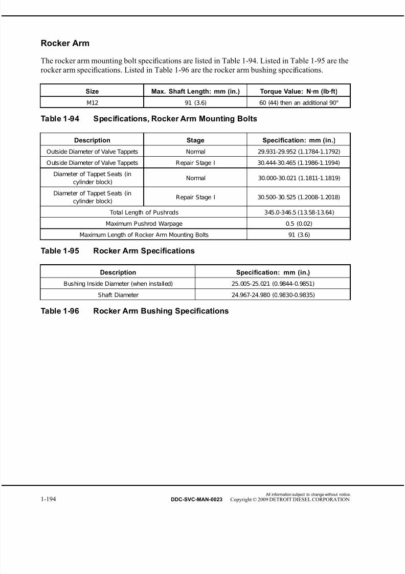
7/22/2019 Manual Mbe 4000 Taller
http://slidepdf.com/reader/full/manual-mbe-4000-taller 238/630
Rocker Arm
The rocker arm mounting bolt specifications are listed in Table 1-94. Listed in Table 1-95 are the
rocker arm specifications. Listed in Table 1-96 are the rocker arm bushing specifications.
Size Max. Shaft Length: mm (in.) Torque Value: N·m (lb·ft)
M12 91 (3.6) 60 (44) then an additional 90°
Table 1-94 Specifications, Rocker Arm Mounting Bolts
Description Stage Specification: mm (in.)
Outside Diameter of Valve Tappets Normal 29.931-29.952 (1.1784-1.1792)
Outside Diameter of Valve Tappets Repair Stage I 30.444-30.465 (1.1986-1.1994)
Diameter of Tappet Seats (in
cylinder block)Normal 30.000-30.021 (1.1811-1.1819)
Diameter of Tappet Seats (in
cylinder block)Repair Stage I 30.500-30.525 (1.2008-1.2018)
Total Length of Pushrods 345.0-346.5 (13.58-13.64)
Maximum Pushrod Warpage 0.5 (0.02)
Maximum Length of Rocker Arm Mounting Bolts 91 (3.6)
Table 1-95 Rocker Arm Specifications
Description Specification: mm (in.)
Bushing Inside Diameter (when installed) 25.005-25.021 (0.9844-0.9851)
Shaft Diameter 24.967-24.980 (0.9830-0.9835)
Table 1-96 Rocker Arm Bushing Specifications
All information subject to change without notice.
1-194 DDC-SVC-MAN-0023 Copyright © 2009 DETROIT DIESEL CORPORATION

7/22/2019 Manual Mbe 4000 Taller
http://slidepdf.com/reader/full/manual-mbe-4000-taller 239/630
MBE 4000 SERVICE MANUAL
Camshaft and Camshaft Sensor
The camshaft specifications arelisted in Table 1-97. The valve tappet specifications are
listed in Table 1-98. Listed in Table 1-99 are the torque values for the camshaft.
What To Measure Where To Measure Value: mm (in.) Unless
otherwise noted
Hardness of Surface At Cams and J ournals 57–63 HRC
Camshaft Radial Runout When
Mounted on Outer Bearing J ournalsAt Gear Seat 0.020 (0.0008)
Camshaft Radial Runout When
Mounted on Outer Bearing J ournalsAt Cam Circle 0.025 (0.0010)
Camshaft Radial Runout When
Mounted on Outer Bearing J ournalsAt C amshaft J ournals 0.030 (0.0012)
Minimum Valve Cam Rise–Above
Basic CircleIntake Valve 7.3 (0.29)
Minimum Valve Cam Rise–AboveBasic Circle
Exhaust Valve 8.2 (0.32)
Camshaft J ournal Diameter For New Camshaft 81.893–81.928 (3.2241–3.2255)
Bushing Diameter At Camshaft J ournals 82.000–82.035 (3.2283–3.2297)
Gear Back Lash Cam Gear to Crank Gear 0.074–0.176 (0.0029–0.0069)
Gear Back Lash Cam Gear to Air Compressor Gear 0.082–0.168 (0.0032–0.0066)
Table 1-97 Camshaft Specifications
Description Repair Stage Specifications: mm (in.)
Tappet Outside Diameter Standard 29.931-29.952 (1.1784-1.1792)
Tappet Outside Diameter Repair Stage I 30.444-30.465 (1.1986-1.1994)
Tappet Housing Diameter (in
cylinder block)Standard 30.000-30.021 (1.1811-1.1819)
Tappet Housing Diameter (in
cylinder block)Repair Stage I 30.500-30.525 (1.2008-1.2018)
Table 1-98 Valve Tappet Specifications
Fastener Type N·m (lb·ft)
Camshaft Front Cover 50 (37)Fuel Pump Drive Gear 60 (44)
Table 1-99 Camshaft Torque Values
All information subject to change without notice.
DDC-SVC-MAN-0023 Copyright © 2009 DETROIT DIESEL CORPORATION 1-195

7/22/2019 Manual Mbe 4000 Taller
http://slidepdf.com/reader/full/manual-mbe-4000-taller 240/630
Sensor and Fittings
The torque specifications for the fuel and coolant temperature sensors as well as some fittings
are listed in Table 1-100.
Description Torque Value: N·m (lb·ft) Unless
otherwise noted
Deaeration Line Banjo Bolt 35 (25)
C onstant T hrottle Valve (CTV) Air S upply L ine Banjo Bolt 45 (33)
Fuel Temperature Sensor to Engine Block 30 (22)
Coolant Temperature S ensor to the E ngine B lock 30 (22)
Trim Cover Bolts 12 (106 lb·in.)
Table 1-100 Sensor and Fittings Torque Values
All information subject to change without notice.
1-196 DDC-SVC-MAN-0023 Copyright © 2009 DETROIT DIESEL CORPORATION

7/22/2019 Manual Mbe 4000 Taller
http://slidepdf.com/reader/full/manual-mbe-4000-taller 241/630
2 FUEL SYSTEM
Section Page
2.1 INJ ECTOR UNIT PUMP ........................................................................... 2-3
2.2 EGR INJ ECTOR UNIT PUMP .................................................................. 2-15
2.3 HIGH PRESSURE FUEL LINE AND TRANSFER TUBE ......................... 2-16
2.4 FUEL INJ ECTOR NOZZLE ...................................................................... 2-26
2.5 EGR FUEL INJ ECTOR NOZZLE ............................................................. 2-34
2.6 PROTECTIVE SLEEVE ........................................................................... 2-35
2.7 DDEC-ELECTRONIC CONTROL UNIT ................................................... 2-39
2.8 FUEL HEAT EXCHANGER ...................................................................... 2-44
2.9 FUEL FILTER ........................................................................................... 2-47
2.10 FUEL FILTER HOUSING ......................................................................... 2-502.11 FUEL FILTER BRACKET ......................................................................... 2-54
2.12 FUEL PUMP ............................................................................................. 2-57
2.13 FUEL PUMP DRIVE ................................................................................. 2-61
2.14 FUEL SY STEM INSPECTION ................................................................. 2-65
2.A ADDITIONAL INFORMATION .................................................................. 2-73

7/22/2019 Manual Mbe 4000 Taller
http://slidepdf.com/reader/full/manual-mbe-4000-taller 242/630
All information subject to change without notice.
2-2 DDC-SVC-MAN-0023 Copyright © 2009 DETROIT DIESEL CORPORATION
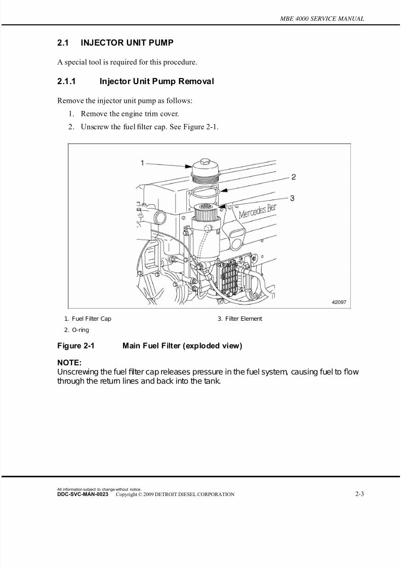
7/22/2019 Manual Mbe 4000 Taller
http://slidepdf.com/reader/full/manual-mbe-4000-taller 243/630
MBE 4000 SERVICE MANUAL
2.1 INJECTOR UNIT PUMP
A special tool is required for this procedure.
2.1.1 Injector Unit Pump Removal
Remove the injector unit pump as follows:
1. Remove the engine trim cover.
2. Unscrew the fuel filter cap. See Figure 2-1.
1. Fuel Filter Cap 3. Filter Element
2. O-ring
Figure 2-1 Main Fuel Filter (exploded view)
NOTE:Unscrewing the fuel filter cap releases pressure in the fuel system, causing fuel to flowthrough the return lines and back into the tank.
All information subject to change without notice.
DDC-SVC-MAN-0023 Copyright © 2009 DETROIT DIESEL CORPORATION 2-3

7/22/2019 Manual Mbe 4000 Taller
http://slidepdf.com/reader/full/manual-mbe-4000-taller 244/630
2.1 INJECTOR UNIT PUMP
3. Disconnect the engine wiring harness from the injector unit pump. See Figure 2-2.
1. Engine Wiring Harness 3. Terminal Screw
2. Terminal 4. Injector Unit Pump
Figure 2-2 Unit Pump Electrical Wires
PERSONAL INJURY
To avoid injury from the sudden release of a high-pressurehose connection, wear a face shield or goggles.
4. Remove the high-pressure fuel injector line. Refer to section 2.3.1.5. Disconnect the fuel line at the fuel gallery inlet. Have a suitable container ready to catch
any fuel that comes out of the cylinder block or fuel line.
All information subject to change without notice.
2-4 DDC-SVC-MAN-0023 Copyright © 2009 DETROIT DIESEL CORPORATION
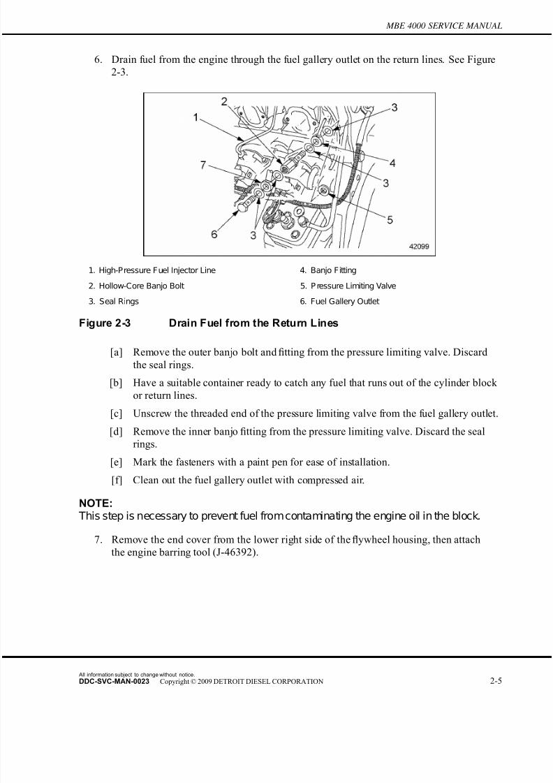
7/22/2019 Manual Mbe 4000 Taller
http://slidepdf.com/reader/full/manual-mbe-4000-taller 245/630
MBE 4000 SERVICE MANUAL
6. Drain fuel from the engine through the fuel gallery outlet on the return lines. See Figure
2-3.
1. High-Pressure Fuel Injector Line 4. Banjo Fitting2. Hollow-Core Banjo Bolt 5. P ressure Limiting Valve
3. Seal Rings 6. Fuel Gallery Outlet
Figure 2-3 Drain Fuel from the Return Lines
[a] Remove the outer banjo bolt and fitting from the pressure limiting valve. Discard
the seal rings.
[b] Have a suitable container ready to catch any fuel that runs out of the cylinder block
or return lines.
[c] Unscrew the threaded end of the pressure limiting valve from the fuel gallery outlet.
[d] Remove the inner banjo fitting from the pressure limiting valve. Discard the seal
rings.
[e] Mark the fasteners with a paint pen for ease of installation.
[f] Clean out the fuel gallery outlet with compressed air.
NOTE: This step is necessary to prevent fuel fromcontaminating the engine oil in the block.
7. Remove the end cover from the lower right side of the flywheel housing, then attach
the engine barring tool (J-46392).
All information subject to change without notice.
DDC-SVC-MAN-0023 Copyright © 2009 DETROIT DIESEL CORPORATION 2-5
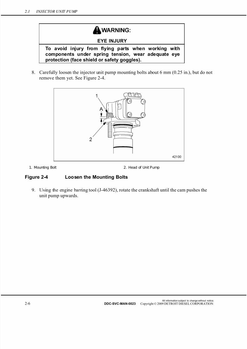
7/22/2019 Manual Mbe 4000 Taller
http://slidepdf.com/reader/full/manual-mbe-4000-taller 246/630
2.1 INJECTOR UNIT PUMP
EYE INJURY
To avoid injury from flying parts when working withcomponents under spring tension, wear adequate eye
protection (face shield or safety goggles).
8. Carefully loosen the injector unit pump mounting bolts about 6 mm (0.25 in.), but do not
remove them yet. See Figure 2-4.
1. Mounting Bolt 2. Head of Unit Pump
Figure 2-4 Loosen the Mounting Bolts
9. Using the engine barring tool (J-46392), rotate the crankshaft until the cam pushes the
unit pump upwards.
All information subject to change without notice.
2-6 DDC-SVC-MAN-0023 Copyright © 2009 DETROIT DIESEL CORPORATION

7/22/2019 Manual Mbe 4000 Taller
http://slidepdf.com/reader/full/manual-mbe-4000-taller 247/630
MBE 4000 SERVICE MANUAL
NOTICE:
If the injector unit pump doesn't come out easily, do not tryto pry up on the body of the pump. This will damage it.
10. If the injector unit pump is locked up, or frozen, in its seat, release it using the blade
of a small screwdriver under thefl
ange where the mounting bolt attaches. See arrowin Figure 2-5.
Figure 2-5 Releasing a Locked-up Pump
11. Remove both mounting bolts completely. Carefully pull the unit pump out of the cylinder
block. See Figure 2-6.
1. Mounting Bolt 3. Cylinder Block
2. Unit Pump
Figure 2-6 Removing the Unit Pump
All information subject to change without notice.
DDC-SVC-MAN-0023 Copyright © 2009 DETROIT DIESEL CORPORATION 2-7

7/22/2019 Manual Mbe 4000 Taller
http://slidepdf.com/reader/full/manual-mbe-4000-taller 248/630
2.1 INJECTOR UNIT PUMP
12. Check the injector unit pump for fuel leakage at the solenoid. If leakage is
found, refer to section 2.1.2.
13. Check the injector unit pump for wear or damage. If any is found replace unit
pump. Refer to section 2.1.3.
14. Remove and discard the two O-rings on the unit pump shaft.
2.1.2 Repairing the Unit Pump Solenoid
A Unit Pump Solenoid repair kit (P/N: 0120740001) is now available for repair of the unit pump.
This service kit is used to repair fuel leakage at the solenoid. For this type of complaint, total
replacement of the unit pump is no longer necessary. Perform the following steps to install the
unit pump repair kit.
All information subject to change without notice.
2-8 DDC-SVC-MAN-0023 Copyright © 2009 DETROIT DIESEL CORPORATION

7/22/2019 Manual Mbe 4000 Taller
http://slidepdf.com/reader/full/manual-mbe-4000-taller 249/630
MBE 4000 SERVICE MANUAL
PERSONAL INJURY
To avoid injury from penetrating fluids, do not put your hands in front of fluid under pressure. Fluids under
pressure can penetrate skin and clothing.
FIRE
To avoid injury from fire, keep all potential ignition sourcesaway from diesel fuel, including open flames, sparks, andelectrical resistance heating elements. Do not smoke whenrefueling.
1. Identify the failed unit pump and failure mode (fuel leak at the solenoid). Remove thefailed unit pump. Refer to section 2.1.1 for unit pump removal procedure. See Figure 2-7.
1. Stop Plate 7. Screw
2. Unit Pump 8. Model Plate
3. Anchor Plate 9. Cross Piece
4. Seal 10. O-ring
5. Intermediate Plate 11. O-ring
6. Magnet
Figure 2-7 Unit Pump Components
2. Wipe the pump clean, removing excess fuel.
All information subject to change without notice.
DDC-SVC-MAN-0023 Copyright © 2009 DETROIT DIESEL CORPORATION 2-9

7/22/2019 Manual Mbe 4000 Taller
http://slidepdf.com/reader/full/manual-mbe-4000-taller 250/630
2.1 INJECTOR UNIT PUMP
3. Remove the O-rings from the unit pump. Push the unit pump O-ring installer (J-45373)
onto the unit pump. This will prevent dirt from entering the unit pump holes.
4. Mark the position of the intermediate plate in relation to the unit pump body (See arrow
A of Figure 2-8) and rest the unit pump on the stop plate. Use a pencil or scribe for
marking. Do not use any stamping tools.
1. Intermediate Plate 3. Special Torx Bit
2. S crew
Figure 2-8 Removing the Magnet and Intermediate Plate
5. Remove all traces of paint from screw heads. Remove screws using the special torx bit
(DDC P/N: 9045890210/00) and lift off the magnet together with the intermediate plate
and model plate. (See arrow B of Figure 2-8).
6. Remove the intermediate plate and the model plate from the magnet. Wipe clean the
sealing surface on the magnet, removing any excess fuel. Clean the model plate and
remove paint from the screw heads contact area.
7. Remove the two spacer seals and clean the intermediate plate. Do not damage sealing
surfaces.
All information subject to change without notice.
2-10 DDC-SVC-MAN-0023 Copyright © 2009 DETROIT DIESEL CORPORATION
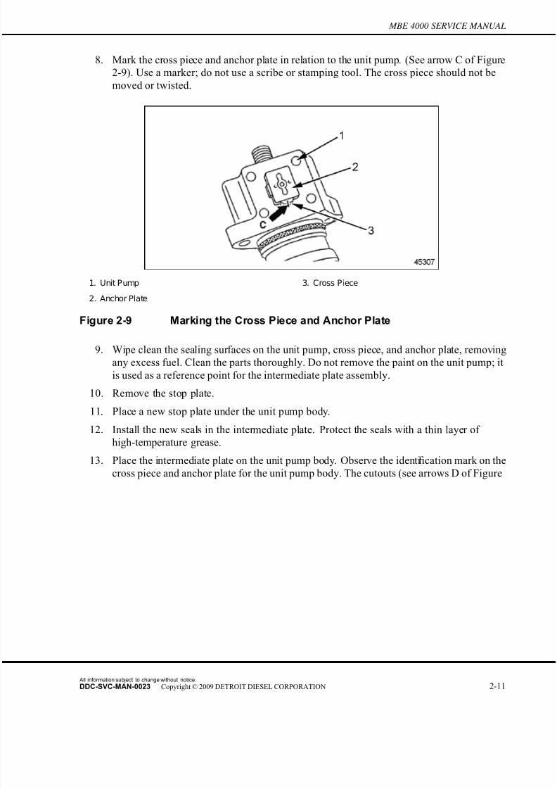
7/22/2019 Manual Mbe 4000 Taller
http://slidepdf.com/reader/full/manual-mbe-4000-taller 251/630
MBE 4000 SERVICE MANUAL
8. Mark the cross piece and anchor plate in relation to the unit pump. (See arrow C of Figure
2-9). Use a marker; do not use a scribe or stamping tool. The cross piece should not be
moved or twisted.
1. Unit Pump 3. Cross Piece
2. Anchor Plate
Figure 2-9 Marking the Cross Piece and Anchor Plate
9. Wipe clean the sealing surfaces on the unit pump, cross piece, and anchor plate, removing
any excess fuel. Clean the parts thoroughly. Do not remove the paint on the unit pump; it
is used as a reference point for the intermediate plate assembly.
10. Remove the stop plate.
11. Place a new stop plate under the unit pump body.12. Install the new seals in the intermediate plate. Protect the seals with a thin layer of
high-temperature grease.
13. Place the intermediate plate on the unit pump body. Observe the identification mark on the
cross piece and anchor plate for the unit pump body. The cutouts (see arrows D of Figure
All information subject to change without notice.
DDC-SVC-MAN-0023 Copyright © 2009 DETROIT DIESEL CORPORATION 2-11
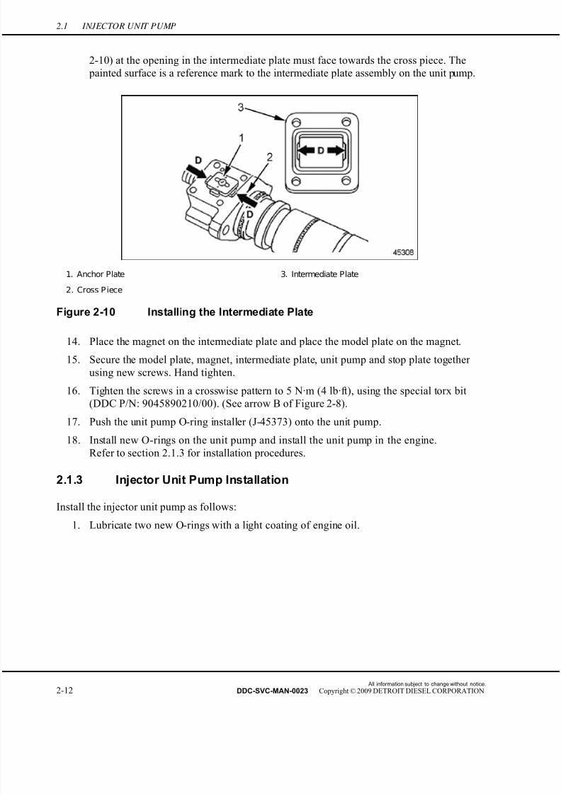
7/22/2019 Manual Mbe 4000 Taller
http://slidepdf.com/reader/full/manual-mbe-4000-taller 252/630

7/22/2019 Manual Mbe 4000 Taller
http://slidepdf.com/reader/full/manual-mbe-4000-taller 253/630
MBE 4000 SERVICE MANUAL
2. Install the two new O-rings on the unit pump shaft using the Unit Pump O-ring installer
(J-45373). See Figure 2-11.
1. Inner (larger) O-ring 2. Outer (smaller) O-ring
Figure 2-11 O-ring Installation
3. Install the injector unit pump into the cylinder block.
[a] Insert the injector unit pump into the mounting hole in the cylinder block.
[b] Use light hand pressure to push in the unit pump until it seats, about 4 mm (0.16 in.).
If it won't seat easily, rotate the crankshaft until the unit pump seats.
NOTE:
Use the bolt mounting holes on the engine as a guide for positioning the injector pump.
4. Install the mounting bolts, and tighten to 65 N·m (48 lb·ft).
5. Connect the engine wiring harness to the injector unit pump.
6. Remove the engine cranking tool and replace the inspection cover on the flywheel housing.
Tighten the inspection cover mounting bolts to 25 N·m (18 lb·ft).
PERSONAL INJURY
To avoid injury from the sudden release of a high-pressurehose connection, wear a face shield or goggles.
7. Connect the fuel line at the fuel gallery inlet. Tighten the fitting to 50 N·m (37 lb·ft).
8. Install the fuel lines and pressure limiting valve on the fuel gallery outlet. Tighten all
fasteners to 50 N·m (37 lb·ft).
All information subject to change without notice.
DDC-SVC-MAN-0023 Copyright © 2009 DETROIT DIESEL CORPORATION 2-13
7/22/2019 Manual Mbe 4000 Taller
http://slidepdf.com/reader/full/manual-mbe-4000-taller 254/630
2.1 INJECTOR UNIT PUMP
[a] Install the inner banjo fitting, and two new seal rings, on the pressure limiting valve,
as marked on removal.
[b] Install the threaded end of the pressure limiting valve in the fuel gallery outlet. When
the valve is firmly seated, tighten to 50 N·m (37 lb·ft).
[c] Install the outer banjo fitting, again with two new seal rings, on the banjo bolt, as
marked on removal.[d] Install the banjo bolt on the pressure limiting valve and tighten to 40-50 N·m (30-37
lb·ft).
9. Install the fuel filter cap. Inspect the O-ring in the fuel filter and replace it if worn. Tighten
the cap nut to 25 N·m (18 lb·ft).
10. Install the high-pressure fuel injector line. Ref er to section 2.3.2.
PERSONAL INJURY
Diesel engine exhaust and some of its constituents areknown to the State of California to cause cancer, birthdefects, and other reproductive harm.□ Always start and operate an engine in a well ventilated
area.□ If operating an engine in an enclosed area, vent the
exhaust to the outside.□ Do not modify or tamper with the exhaust system or
emission control system.
11. Prime the fuel system.
12. Start the engine and check for leaks. Tighten connections as needed.
13. Install the engine trim cover.
All information subject to change without notice.
2-14 DDC-SVC-MAN-0023 Copyright © 2009 DETROIT DIESEL CORPORATION

7/22/2019 Manual Mbe 4000 Taller
http://slidepdf.com/reader/full/manual-mbe-4000-taller 255/630
MBE 4000 SERVICE MANUAL
2.2 EGR INJECTOR UNIT PUMP
The removal and installation of the EGR injector unit pump is the same as the non-EGR e ngine;
however, the EGR injector unit pump must be programmed to coordinate with the DDEC-ECU
(formerly PLD-MR).
2.2.1 EGR Injector Unit Pump Programming
When replacing and before installing a new EPA 04 EGR unit pump, the unit pump identification
code number must be programmed into the DDEC-ECU (PLD-MR). Perform the following
procedures to insert this code into the unit pump:
NOTE:On the top surface of each EGR unit pump, there is a unit pump identification codenumber. This is the number that is programmed into the DDEC-ECU (formerly PLD-MR)to coordinate the operation of the unit pumps. See Figure 2-12.
1. Injector Unit Pump 2. Injector Unit Pump Identification Number
Figure 2-12 Injector Unit Pump Identification Number
1. Consult the minidiag2 manual for service routines.
2. Select routine number 006 – Pump Line Nozzle Change.
3. Enter the unit pump identification Number found on the top of the unit pump.
4. Press enter.
5. Press double-ar row back key.
6. Turn off key and unplug minidiag2.
7. Install the unit pump. Refer to section 2.1.3.
All information subject to change without notice.
DDC-SVC-MAN-0023 Copyright © 2009 DETROIT DIESEL CORPORATION 2-15

7/22/2019 Manual Mbe 4000 Taller
http://slidepdf.com/reader/full/manual-mbe-4000-taller 256/630
2.3 HIGH PRESSURE FUEL LINE AND TRANSFER TUBE
2.3 HIGH PRESSURE FUEL LINE AND TRANSFER TUBE
The following sections support the repair of the high pressure fuel line and transfer tubes.
NOTICE:
When replacing high pressure fuel line(s), always replace the
associated transfer tube. High pressure fuel lines and transfertubes are one-time use components. Always discard theoldhighpressure fuel line and transfer tube.
NOTICE:
Any repair to the fuel system requires the fuel tank cap to beremoved, to release any trapped air pressure in the fuel tank.
2.3.1 Removal of High Pressure Fuel Line and Transfer Tube
Remove as follows:
All information subject to change without notice.
2-16 DDC-SVC-MAN-0023 Copyright © 2009 DETROIT DIESEL CORPORATION

7/22/2019 Manual Mbe 4000 Taller
http://slidepdf.com/reader/full/manual-mbe-4000-taller 257/630
MBE 4000 SERVICE MANUAL
PERSONAL INJURY
To prevent the escape of high pressure fuel that canpenetrate skin, ensure the engine has been shut down for
a minimum of 10 minutes before servicing any componentwithin the high pressure circuit. Residual high fuelpressure may be present within the circuit.
FIRE
To avoid injury from fire, keep all potential ignition sourcesaway from diesel fuel, including open flames, sparks, andelectrical resistance heating elements. Do not smoke when
refueling.
FIRE
To avoid injury from fire caused by heated diesel-fuelvapors:□ Keep those people who are not directly involved in
servicing away from the engine.□ Stop the engine immediately if a fuel leak is detected.
□ Do not smoke or allow open flames when working onan operating engine.
□ Wear adequate protective clothing (face shield,insulated gloves and apron, etc.).
□ To prevent a buildup of potentially volatile vapors, keepthe engine area well ventilated during operation.
1. Remove both engine trim cover s.
2. Remove the cylinder head cover for each cylinder head.
3. Remove the intake manifold.
4. To prevent the transfer tube from rotating during the high pressure fuel line disassembly,
secure the transfer tube thrust nut using a 24 mm fuel line wrench (J-47484 or J-45063)
All information subject to change without notice.
DDC-SVC-MAN-0023 Copyright © 2009 DETROIT DIESEL CORPORATION 2-17

7/22/2019 Manual Mbe 4000 Taller
http://slidepdf.com/reader/full/manual-mbe-4000-taller 258/630
2.3 HIGH PRESSURE FUEL LINE AND TRANSFER TUBE
and loosen the high pressure fuel line nut at the transfer tube using a 17 mm fuel line
wrench (J-47483) or a 17 mm open end wrench. See Figure 2-13.
1.High Pressure Fuel Injector Line Nut (Injector UnitPump)
3. High Pressure Fuel Injector Line Nut(Transfer Tube)
2. High Pressure Fuel Injector Line 4. Transfer Tube Thrust Nut
Figure 2-13 High Pressure Fuel Injector Line
PERSONAL INJURY
To avoid injury from the sudden release of a high pressurehose connection, wear a face shield or goggles.
NOTICE:
The high pressure fuel line and transfer tube are one-time useitems. Failure to install a new highpressure fuel line and transfertube will cause fuel leaks and high pressure fuel line failures.
5. Using a 17 mm fuel line wrench (J-47483) or a 17 mm open end wrench, loosen the
high pressure fuel injector line nut at the injector unit pump. Discard the high pressure
fuel injector line. See Figure 2-13.
6. Using a 24 mm fuel line wrench (J-45063 or J-47484), loosen the thrust nut on the transfer tube. Remove and discard the transfer tube and the O-ring. See Figure 2-13.
2.3.2 Installation of High Pressure Fuel Injector Lines
Installation steps are as follows:
All information subject to change without notice.
2-18 DDC-SVC-MAN-0023 Copyright © 2009 DETROIT DIESEL CORPORATION
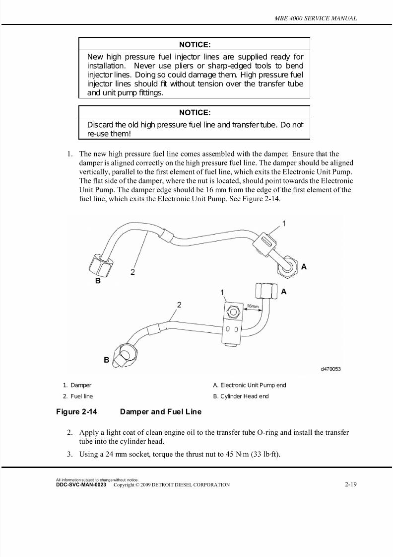
7/22/2019 Manual Mbe 4000 Taller
http://slidepdf.com/reader/full/manual-mbe-4000-taller 259/630
MBE 4000 SERVICE MANUAL
NOTICE:
New high pressure fuel injector lines are supplied ready forinstallation. Never use pliers or sharp-edged tools to bendinjector lines. Doing so could damage them. High pressure fuelinjector lines should fit without tension over the transfer tubeand unit pump fittings.
NOTICE:
Discard the old high pressure fuel line and transfer tube. Do notre-use them!
1. The new high pressure fuel line comes assembled with the damper. Ensure that the
damper is aligned correctly on the high pressur e fuel line. The damper should be aligned
vertically, parallel to the first element of fuel line, which exits the Electronic Unit Pump.
The flat side of the damper, where the nut is located, should point towards the Electronic
Unit Pump. The damper edge should be 16 mm from the edge of the first element of the
fuel line, which exits the Electronic Unit Pump. See Figure 2-14.
1. Damper A. Electronic Unit Pump end
2. Fuel line B. Cylinder Head end
Figure 2-14 Damper and Fuel Line
2. Apply a light coat of clean engine oil to the transfer tube O-ring and install the transfer
tube into the cylinder head.
3. Using a 24 mm socket, torque the thrust nut to 45 N·m (33 lb·ft).
All information subject to change without notice.
DDC-SVC-MAN-0023 Copyright © 2009 DETROIT DIESEL CORPORATION 2-19
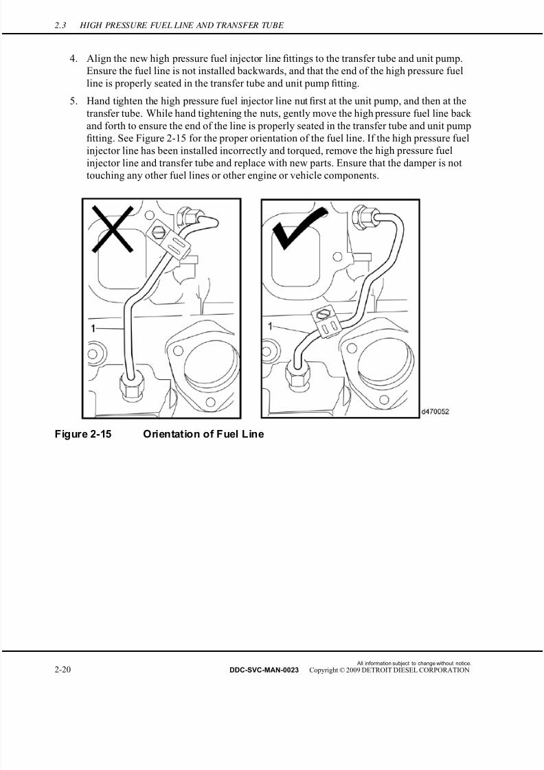
7/22/2019 Manual Mbe 4000 Taller
http://slidepdf.com/reader/full/manual-mbe-4000-taller 260/630
2.3 HIGH PRESSURE FUEL LINE AND TRANSFER TUBE
4. Align the new high pressure fuel injector line fittings to the transfer tube and unit pump.
Ensure the fuel line is not installed backwards, and that the end of the high pressur e fuel
line is properly seated in the transfer tube and unit pump fitting.
5. Hand tighten the high pressure fuel injector line nut first at the unit pump, and then at the
transfer tube. While hand tightening the nuts, gently move the high pressure fuel line back
and forth to ensure the end of the line is properly seated in the transfer tube and unit pump
fitting. See Figure 2-15 for the proper orientation of the fuel line. If the high pressure fuelinjector line has been installed incorrectly and torqued, remove the high pressure fuel
injector line and transfer tube and replace with new parts. Ensure that the damper is not
touching any other fuel lines or other engine or vehicle components.
Figure 2-15 Orientation of Fuel Line
All information subject to change without notice.
2-20 DDC-SVC-MAN-0023 Copyright © 2009 DETROIT DIESEL CORPORATION

7/22/2019 Manual Mbe 4000 Taller
http://slidepdf.com/reader/full/manual-mbe-4000-taller 261/630
MBE 4000 SERVICE MANUAL
6. Once the high pressure fuel injector line nuts are hand tight, draw a vertical line with a
highly visible marker along the front edge of both of the nuts and up the fuel line. The line
drawn along the edge of the nuts and the fuel line should be aligned. See Figure 2-16.
1. Electronic Unit P ump E nd 2. Transfer Tube End
Figure 2-16 Marking Of High Pressure Fuel Injector Line And Nuts
7. Using a 17 mm fuel line wrench (J-47483) or a 17 mm open end wrench, tighten the high
pressure fuel line nut at the unit pump end by turning the nut through 120 degrees. 120degrees can be measured by turning the nut so that the nut edge which had been marked
has been turned through 1/3 of a full turn, or through two nut flats. Lack of space in some
All information subject to change without notice.
DDC-SVC-MAN-0023 Copyright © 2009 DETROIT DIESEL CORPORATION 2-21
7/22/2019 Manual Mbe 4000 Taller
http://slidepdf.com/reader/full/manual-mbe-4000-taller 262/630
2.3 HIGH PRESSURE FUEL LINE AND TRANSFER TUBE
engine configurations may mean that the 120 degree turn will have to be completed in two
turns of 60 degrees, or one nut flat each. See Figure 2-17.
Figure 2-17 Turning Fuel Line Nut 120 Degrees at Unit Pump End
8. Use a 24 mm fuel line wrench (J-45063 or J-47484), hold the transfer tube thrust nut.
Using a 17 mm fuel line wrench (J-47483) or a 17 mm open end wrench, tighten the high
pressure fuel injector line nut at the transfer tube end by turning the nut through 120
degrees. 120 degrees can be measured by turning the nut so that the nut edge which had
been marked has been turned through 1/3 of a full turn, or through two nut flats. Lack of
All information subject to change without notice.
2-22 DDC-SVC-MAN-0023 Copyright © 2009 DETROIT DIESEL CORPORATION

7/22/2019 Manual Mbe 4000 Taller
http://slidepdf.com/reader/full/manual-mbe-4000-taller 263/630
MBE 4000 SERVICE MANUAL
space in some engine configurations may mean that the 120 degree turn will have to be
completed in two turns of 60 degrees, or one nut flat each. See Figure 2-18.
Figure 2-18 Turning Fuel Line Nut 120 Degrees At Transfer Tube End
All information subject to change without notice.
DDC-SVC-MAN-0023 Copyright © 2009 DETROIT DIESEL CORPORATION 2-23
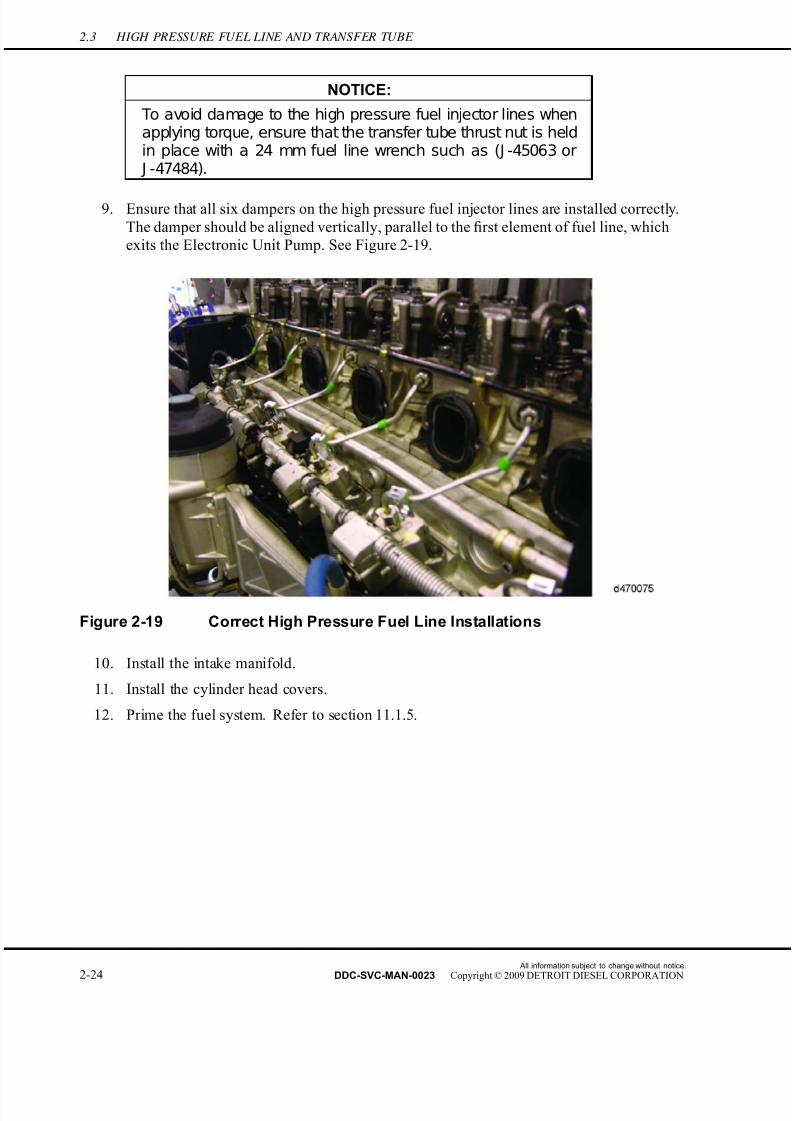
7/22/2019 Manual Mbe 4000 Taller
http://slidepdf.com/reader/full/manual-mbe-4000-taller 264/630
2.3 HIGH PRESSURE FUEL LINE AND TRANSFER TUBE
NOTICE:
To avoid damage to the high pressure fuel injector lines whenapplying torque, ensure that the transfer tube thrust nut is heldin place with a 24 mm fuel line wrench such as (J -45063 or J -47484).
9. Ensure that all six dampers on the high pressure fuel injector lines are installed correctly.
The damper should be aligned vertically, parallel to the first element of fuel line, which
exits the Electronic Unit Pump. See Figure 2-19.
Figure 2-19 Correct High Pressure Fuel Line Installations
10. Install the intake manifold.
11. Install the cylinder head covers.
12. Prime the fuel system. Refer to section 11.1.5.
All information subject to change without notice.
2-24 DDC-SVC-MAN-0023 Copyright © 2009 DETROIT DIESEL CORPORATION

7/22/2019 Manual Mbe 4000 Taller
http://slidepdf.com/reader/full/manual-mbe-4000-taller 265/630
MBE 4000 SERVICE MANUAL
EXHAUST FUMES
To avoid injury or injury to bystanders from fumes, engineor vehicle fuel system service operations should be
performed in a well ventilated area.
NOTICE:
Do NOT loosen any high pressure fuel injector line nuts or otherfuel line connections for priming purposes. Use the priming porton the fuel filter housing for engine S/N 0460810824 (EGR) orS/N 0460805219 (non-EGR) and higher. Engines built prior tothe change points will have the priming port installed throughCampaigns 06C-2 (EGR) and 06C-1 (non-EGR). Never loosenfuel line connections to bleed air from the fuel system.
13. Run the engine and check for leaks.
NOTICE:
Do NOT re-torque high pressure fuel injector line nuts. If leaksare detected after installation, remove the necessary highpressure fuel injector line and transfer tube, discard them, andinstall new parts.
14. Shut down the engine.
All information subject to change without notice.
DDC-SVC-MAN-0023 Copyright © 2009 DETROIT DIESEL CORPORATION 2-25
7/22/2019 Manual Mbe 4000 Taller
http://slidepdf.com/reader/full/manual-mbe-4000-taller 266/630
2.4 FUEL INJECTOR NOZZLE
2.4 FUEL INJECTOR NOZZLE
Perform the following procedures for removal and installation of the fuel injector nozzle.
2.4.1 Fuel Injector Nozzle Removal
Remove the fuel injector nozzle as follows:
1. Remove the engine trim covers.
NOTE: The MBE 4000 engine has individual heads for each cylinder. To remove the injectornozzle for one cylinder, do these procedures step by step. To remove all the injectornozzles, repeat each step in these instructions, as applicable, for all six cylinders.
2. Remove the cylinder head cover for each cylinder head, as required.
3. Remove the charge-air manifold.
FIRE
To avoid injury from fire, keep all potential ignition sourcesaway from diesel fuel, including open flames, sparks, andelectrical resistance heating elements. Do not smoke whenrefueling.
FIRE
To avoid injury from fire caused by heated diesel-fuelvapors:□ Keep those people who are not directly involved in
servicing away from the engine.□ Stop the engine immediately if a fuel leak is detected.□ Do not smoke or allow open flames when working on
an operating engine.□ Wear adequate protective clothing (face shield,
insulated gloves and apron, etc.).□ To prevent a buildup of potentially volatile vapors, keep
the engine area well ventilated during operation.
All information subject to change without notice.
2-26 DDC-SVC-MAN-0023 Copyright © 2009 DETROIT DIESEL CORPORATION
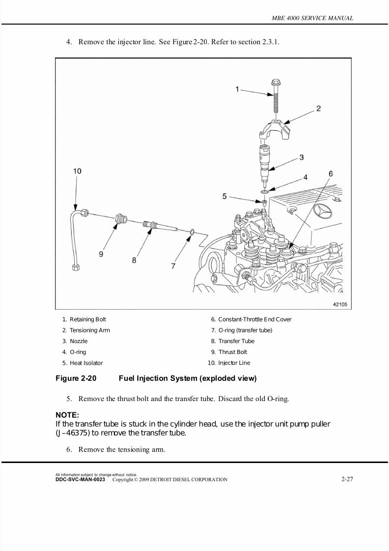
7/22/2019 Manual Mbe 4000 Taller
http://slidepdf.com/reader/full/manual-mbe-4000-taller 267/630
MBE 4000 SERVICE MANUAL
4. Remove the injector line. See Figure 2-20. Refer to section 2.3.1.
1. Retaining Bolt 6. Constant-Throttle End Cover
2. Tensioning Arm 7. O-ring (transfer tube)
3. Nozzle 8. Transfer Tube
4. O-ring 9. Thrust Bolt
5. Heat Isolator 10. Injector Line
Figure 2-20 Fuel Injection System (exploded view)
5. Remove the thrust bolt and the transfer tube. Discard the old O-ring.
NOTE:If the transfer tube is stuck in the cylinder head, use the injector unit pump puller(J –46375) to remove the transfer tube.
6. Remove the tensioning arm.
All information subject to change without notice.
DDC-SVC-MAN-0023 Copyright © 2009 DETROIT DIESEL CORPORATION 2-27

7/22/2019 Manual Mbe 4000 Taller
http://slidepdf.com/reader/full/manual-mbe-4000-taller 268/630
2.4 FUEL INJECTOR NOZZLE
7. Attach the injector unit pump puller (J-46375) and adaptor (J-46384). Thread the narrow
end of the adaptor onto the internal M8 threading in the head of the nozzle. Thread th e
impact extractor onto the wide end of the adaptor. See Figure 2-21.
1. Nozzle 3. Heat Isolator
2. O-ring 4. Constant-Throttle End Cover
Figure 2-21 Pulling the Nozzle
NOTE:Do not attempt to take apart the nozzle. If there is a problem, replace the nozzle.
8. Using the impact extractor (J-46375), remove the nozzle from the cylinder head. Discard
the O-ring and the heat isolator.
NOTICE:
Pull the nozzle straight out of the cylinder head. Do not twist it,turn it, or use pliers. This could damage the nozzle.
9. Remove the impact extractor (J-46375) and adaptor (J-46384) from the nozzle.
10. Remove the O-ring and heat isolator from the nozzle holder and discard. If necessary,
remove the heat isolator from the cylinder head using the heat isolator puller (J-46933).
[a] Install the end of the puller (J-46933) into the tip in the cylinder head. Turn the
shaft of the tool to expand into the tip.
[b] Use the slide hammer on the puller tool and remove and discard the heat isolator.
11. Cap off or cover the openings on the unit pump and nozzle to prevent contamination.
All information subject to change without notice.
2-28 DDC-SVC-MAN-0023 Copyright © 2009 DETROIT DIESEL CORPORATION
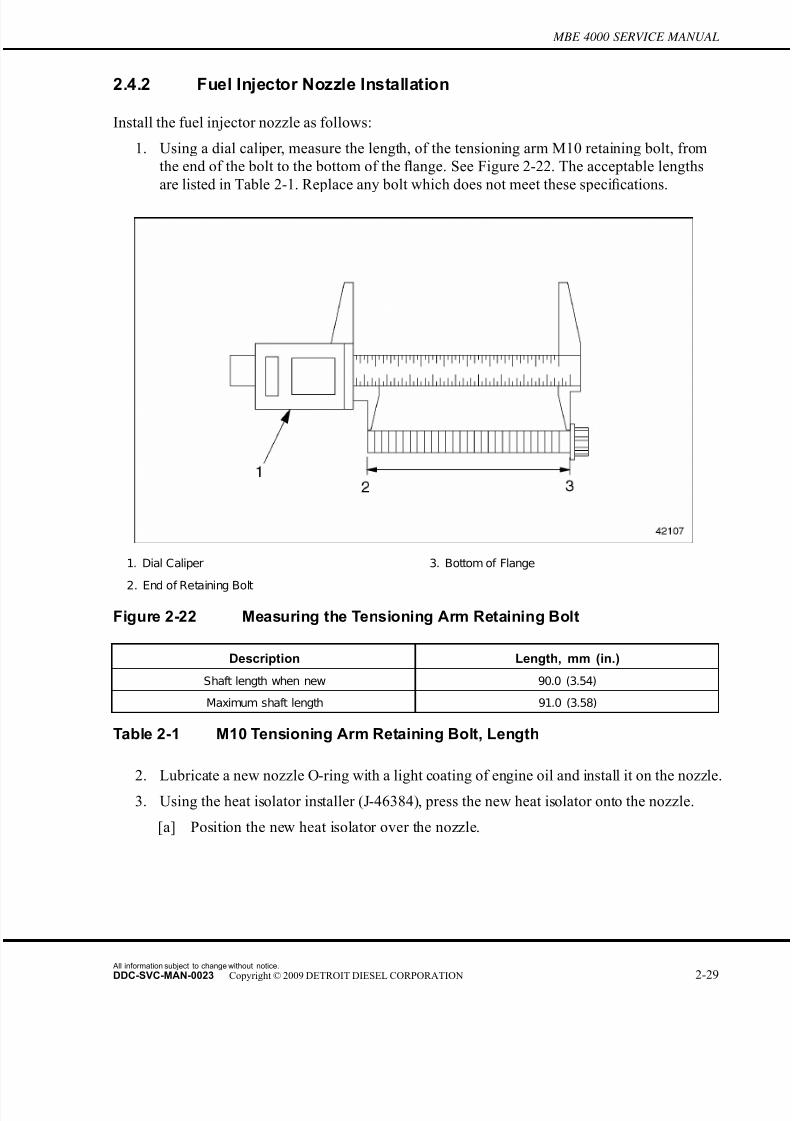
7/22/2019 Manual Mbe 4000 Taller
http://slidepdf.com/reader/full/manual-mbe-4000-taller 269/630
MBE 4000 SERVICE MANUAL
2.4.2 Fuel Injector Nozzle Installation
Install the fuel injector nozzle as follows:
1. Using a dial caliper, measure the length, of the tensioning arm M10 retaining bolt, from
the end of the bolt to the bottom of the flange. See Figure 2-22. The acceptable lengths
are listed in Table 2-1. Replace any bolt which does not meet these specifications.
1. Dial Caliper 3. Bottom of Flange
2. End of Retaining Bolt
Figure 2-22 Measuring the Tensioning Arm Retaining Bolt
Description Length, mm (in.)
Shaft length when new 90.0 (3.54)
Maximum shaft length 91.0 (3.58)
Table 2-1 M10 Tensioning Arm Retaining Bolt, Length
2. Lubricate a new nozzle O-ring with a light coating of engine oil and install it on the nozzle.
3. Using the heat isolator installer (J-46384), press the new heat isolator onto the nozzle.
[a] Position the new heat isolator over the nozzle.
All information subject to change without notice.
DDC-SVC-MAN-0023 Copyright © 2009 DETROIT DIESEL CORPORATION 2-29

7/22/2019 Manual Mbe 4000 Taller
http://slidepdf.com/reader/full/manual-mbe-4000-taller 270/630
2.4 FUEL INJECTOR NOZZLE
[b] Place the receptacle from the heat isolator installer over the head of the nozzle holder
and the pressure-fit cap over the heat isolator. See Figure 2-23 and see Figure 2-24.
Figure 2-23 Heat Isolator Installer Components (J-46393)
All information subject to change without notice.
2-30 DDC-SVC-MAN-0023 Copyright © 2009 DETROIT DIESEL CORPORATION
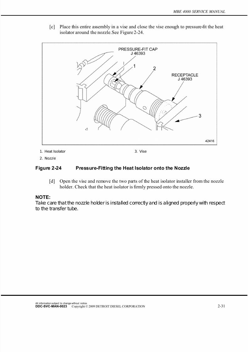
7/22/2019 Manual Mbe 4000 Taller
http://slidepdf.com/reader/full/manual-mbe-4000-taller 271/630
MBE 4000 SERVICE MANUAL
[c] Place this entire assembly in a vise and close the vise enough to pressure-fit the heat
isolator around the nozzle.See Figure 2-24.
1. Heat Isolator 3. Vise
2. Nozzle
Figure 2-24 Pressure-Fitting the Heat Isolator onto the Nozzle
[d] Open the vise and remove the two parts of the heat isolator installer from the nozzle
holder. Check that the heat isolator is firmly pressed onto the nozzle.
NOTE: Take care that the nozzle holder is installed correctly and is aligned properly with respectto the transfer tube.
All information subject to change without notice.
DDC-SVC-MAN-0023 Copyright © 2009 DETROIT DIESEL CORPORATION 2-31

7/22/2019 Manual Mbe 4000 Taller
http://slidepdf.com/reader/full/manual-mbe-4000-taller 272/630
2.4 FUEL INJECTOR NOZZLE
4. Install the nozzle in the cylinder head. Align the notch in the tensioning arm with the pin
on the top of the nozzle.See arrow in Figure 2-25.
1. Injector Line Fitting 7. Retaining Bolt
2. Thrust Bolt 8. Tensioning Arm
3. O-ring (transfer tube) 9. E nd Cover (Constant-Throttle)
4. Transfer Tube 10. Heat Isolator
5. Nozzle 11. Protective Sleeve
6. O-ring (nozzle)
Figure 2-25 Positioning the Nozzle
5. Install the retaining bolt in the tensioning arm. Tighten the bolt 50 N·m (37 lb·ft).
NOTE: The tensioning arm insures the correct positioning of the nozzle.
All information subject to change without notice.
2-32 DDC-SVC-MAN-0023 Copyright © 2009 DETROIT DIESEL CORPORATION
7/22/2019 Manual Mbe 4000 Taller
http://slidepdf.com/reader/full/manual-mbe-4000-taller 273/630
MBE 4000 SERVICE MANUAL
6. Lubricate a new transfer-tube O-ring with a light coating of engine oil and install it on the
transfer tube.
NOTE:Do not tighten the thrust bolt until after the tensioning arm has been fully tightened tothe correct torque value.
7. Install the transfer tube in the cylinder head. Tighten the thrust bolt 45 N·m (33 lb·ft).
8. Install the injector line. Refer to section 2.3.2.
9. Install the charge-air manifold.
10. Install the cylinder head cover(s), as removed.
11. Install the engine trim covers.
All information subject to change without notice.
DDC-SVC-MAN-0023 Copyright © 2009 DETROIT DIESEL CORPORATION 2-33
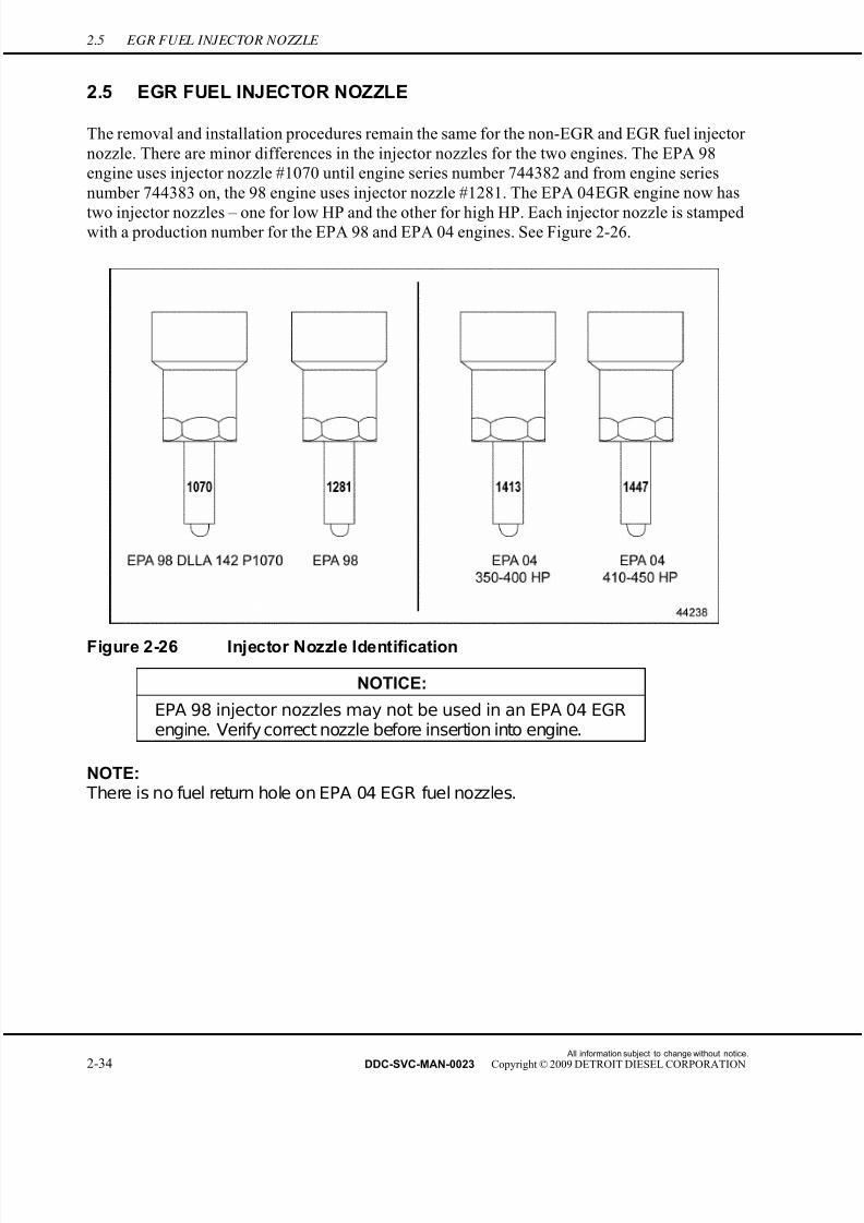
7/22/2019 Manual Mbe 4000 Taller
http://slidepdf.com/reader/full/manual-mbe-4000-taller 274/630
2.5 EGR FUEL INJECTOR NOZZLE
2.5 EGR FUEL INJECTOR NOZZLE
The removal and installation procedures remain the same for the non-EGR and EGR fuel injector
nozzle. There are minor differences in the injector nozzles for the two engines. The EPA 98
engine uses injector nozzle #1070 until engine series number 744382 and from engine series
number 744383 on, the 98 engine uses injector nozzle #1281. The EPA 04 EGR engine now has
two injector nozzles – one for low HP and the other for high HP. Each injector nozzle is stampedwith a production number for the EPA 98 and EPA 04 engines. See Figure 2-26.
Figure 2-26 Injector Nozzle Identification
NOTICE:
EPA 98 injector nozzles may not be used in an EPA 04 EGRengine. Verify correct nozzle before insertion into engine.
NOTE: There is no fuel return hole on EPA 04 EGR fuel nozzles.
All information subject to change without notice.
2-34 DDC-SVC-MAN-0023 Copyright © 2009 DETROIT DIESEL CORPORATION

7/22/2019 Manual Mbe 4000 Taller
http://slidepdf.com/reader/full/manual-mbe-4000-taller 275/630
MBE 4000 SERVICE MANUAL
2.6 PROTECTIVE SLEEVE
Perform the following procedures for removal and installation of the protective sleeve.
2.6.1 Protective Sleeve Removal
Remove the protective sleeve as follows:
HOT COOLANT
To avoid scalding from the expulsion of hot coolant, never remove the cooling system pressure cap while the engineis at operating temperature. Wear adequate protectiveclothing (face shield, rubber gloves, apron, and boots).Remove the cap slowly to relieve pressure.
1. Drain the engine coolant into a clean container. If the coolant is clean, save it for later use.
2. Remove the injector nozzle. Refer to section 2.4.1.
3. Remove the protective sleeve from the cylinder head by performing the following steps:
1. Protective Sleeve 2. O-ring
Figure 2-27 Removing the Protective Sleeve
[a] Insert the 4-toothed socket (J-46186) into the protective sleeve. Make sure the teeth
of the socket engage the four openings on the protective sleeve. See Figure 2-27.
[b] Loosen the protective sleeve with a ratchet by turning in a counterclockwise direction
until the threads of the sleeve are disengaged from the cylinder head.
All information subject to change without notice.
DDC-SVC-MAN-0023 Copyright © 2009 DETROIT DIESEL CORPORATION 2-35
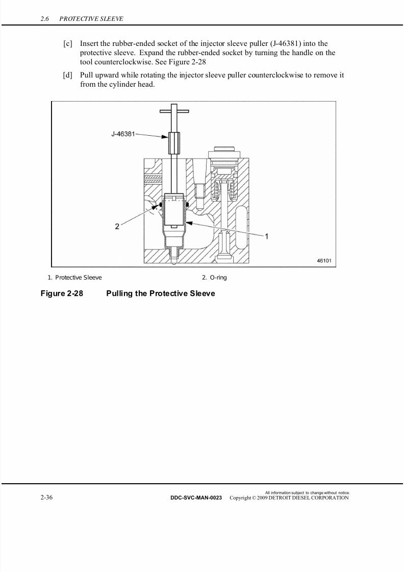
7/22/2019 Manual Mbe 4000 Taller
http://slidepdf.com/reader/full/manual-mbe-4000-taller 276/630
2.6 PROTECTIVE SLEEVE
[c] Insert the rubber-ended socket of the injector sleeve puller (J-46381) into the
protective sleeve. Expand the rubber-ended socket by turning the handle on the
tool counterclockwise. See Figure 2-28
[d] Pull upward while rotating the injector sleeve puller counterclockwise to remove it
from the cylinder head.
1. Protective Sleeve 2. O-ring
Figure 2-28 Pulling the Protective Sleeve
All information subject to change without notice.
2-36 DDC-SVC-MAN-0023 Copyright © 2009 DETROIT DIESEL CORPORATION
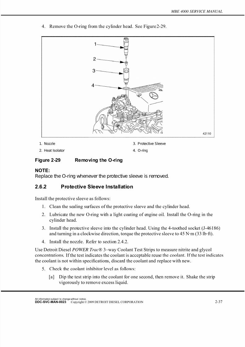
7/22/2019 Manual Mbe 4000 Taller
http://slidepdf.com/reader/full/manual-mbe-4000-taller 277/630
MBE 4000 SERVICE MANUAL
4. Remove the O-ring from the cylinder head. See Figure 2-29.
1. Nozzle 3. Protective Sleeve
2. Heat Isolator 4. O-ring
Figure 2-29 Removing the O-ring
NOTE:Replace the O-ring whenever the protective sleeve is removed.
2.6.2 Protective Sleeve Installation
Install the protective sleeve as follows:
1. Clean the sealing surfaces of the protective sleeve and the cylinder head.
2. Lubricate the new O-ring with a light coating of engine oil. Install the O-ring in the
cylinder head.
3. Install the protective sleeve into the cylinder head. Using the 4-toothed socket (J-46186)
and turning in a clockwise direction, torque the protective sleeve to 45 N·m (33 lb·ft).
4. Install the nozzle. Refer to section 2.4.2.Use Detroit Diesel POWER Trac® 3–way Coolant Test Strips to measure nitrite and glycol
concentrations. If the test indicates the coolant is acceptable reuse the coolant. If the test indicates
the coolant is not within specifications, discard the coolant and replace with new.
5. Check the coolant inhibitor level as follows:
[a] Dip the test strip into the coolant for one second, then remove it. Shake the strip
vigorously to remove excess liquid.
All information subject to change without notice.
DDC-SVC-MAN-0023 Copyright © 2009 DETROIT DIESEL CORPORATION 2-37
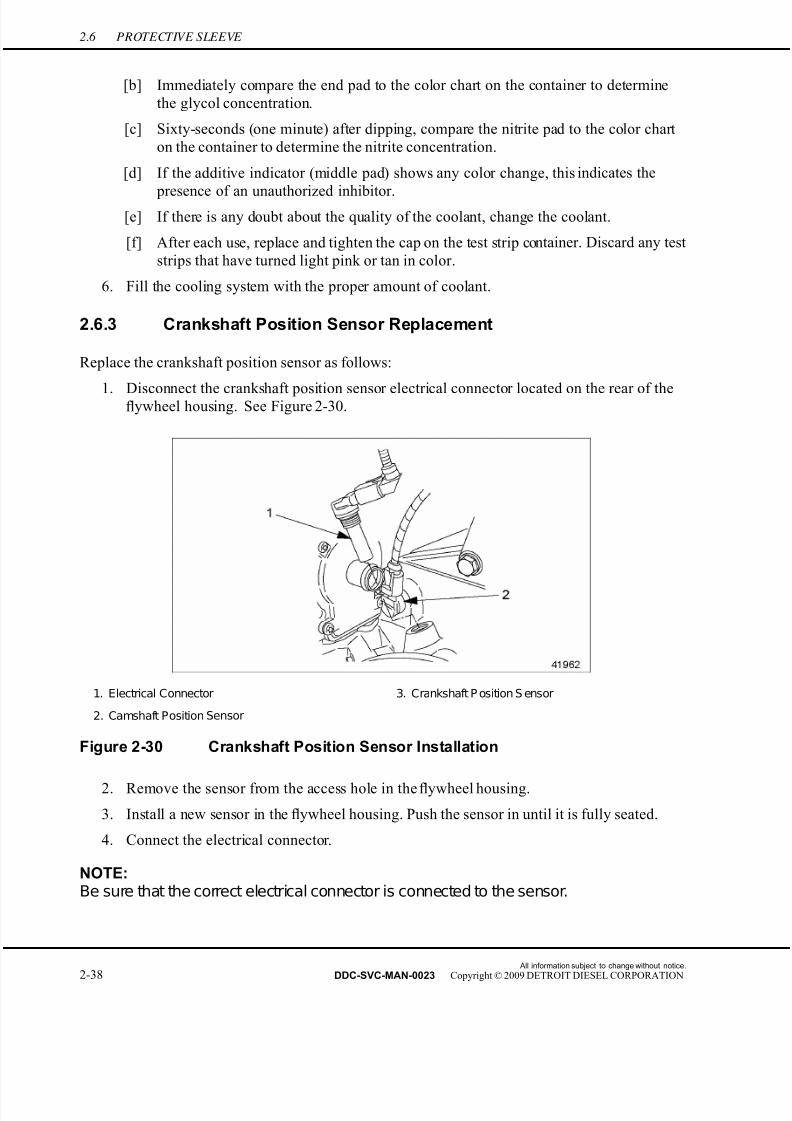
7/22/2019 Manual Mbe 4000 Taller
http://slidepdf.com/reader/full/manual-mbe-4000-taller 278/630
2.6 PROTECTIVE SLEEVE
[b] Immediately compare the end pad to the color chart on the container to determine
the glycol concentration.
[c] Sixty-seconds (one minute) after dipping, compare the nitrite pad to the color chart
on the container to determine the nitrite concentration.
[d] If the additive indicator (middle pad) shows any color change, this indicates the
presence of an unauthorized inhibitor.[e] If there is any doubt about the quality of the coolant, change the coolant.
[f] After each use, replace and tighten the cap on the test strip container. Discard any test
strips that have turned light pink or tan in color.
6. Fill the cooling system with the proper amount of coolant.
2.6.3 Crankshaft Position Sensor Replacement
Replace the crankshaft position sensor as f ollows:
1. Disconnect the crankshaft position sensor electrical connector located on the rear of theflywheel housing. See Figure 2-30.
1. Electrical Connector 3. Crankshaft P osition S ensor
2. Camshaft Position Sensor
Figure 2-30 Crankshaft Position Sensor Installation
2. Remove the sensor from the access hole in the flywheel housing.
3. Install a new sensor in the flywheel housing. Push the sensor in until it is fully seated.
4. Connect the electrical connector.
NOTE:Be sure that the correct electrical connector is connected to the sensor.
All information subject to change without notice.
2-38 DDC-SVC-MAN-0023 Copyright © 2009 DETROIT DIESEL CORPORATION

7/22/2019 Manual Mbe 4000 Taller
http://slidepdf.com/reader/full/manual-mbe-4000-taller 279/630
MBE 4000 SERVICE MANUAL
2.7 DDEC-ELECTRONIC CONTROL UNIT
Perform the following procedures for removal and installation of the DDEC-ECU.
2.7.1 DDEC-Electronic Control Unit Removal
Remove the DDEC-ECU as follows:
1. Disconnect the batteries.
2. Open the hood.
All information subject to change without notice.
DDC-SVC-MAN-0023 Copyright © 2009 DETROIT DIESEL CORPORATION 2-39
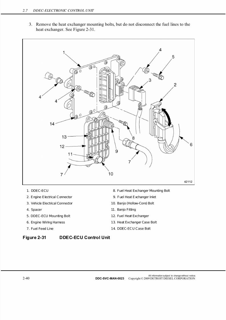
7/22/2019 Manual Mbe 4000 Taller
http://slidepdf.com/reader/full/manual-mbe-4000-taller 280/630
2.7 DDEC-ELECTRONIC CONTROL UNIT
3. Remove the heat exchanger mounting bolts, but do not disconnect the fuel lines to the
heat exchanger. See Figure 2-31.
1. DDEC-ECU 8. Fuel Heat Exchanger Mounting Bolt
2. E ngine E lectrical C onnector 9. F uel Heat E xchanger Inlet
3. Vehicle Electrical Connector 10. Banjo (Hollow-Core) Bolt
4. Spacer 11. Banjo Fitting
5. DDEC-ECU Mounting Bolt 12. Fuel Heat Exchanger
6. Engine Wiring Harness 13. Heat Exchanger Case Bolt
7. Fuel Feed Line 14. DDEC-EC U C ase Bolt
Figure 2-31 DDEC-ECU Control Unit
All information subject to change without notice.
2-40 DDC-SVC-MAN-0023 Copyright © 2009 DETROIT DIESEL CORPORATION
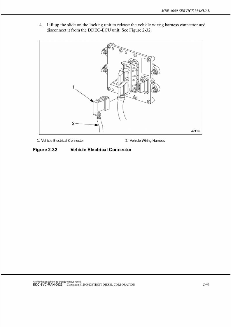
7/22/2019 Manual Mbe 4000 Taller
http://slidepdf.com/reader/full/manual-mbe-4000-taller 281/630

7/22/2019 Manual Mbe 4000 Taller
http://slidepdf.com/reader/full/manual-mbe-4000-taller 282/630
2.7 DDEC-ELECTRONIC CONTROL UNIT
5. Rotate the safety latch down to release the engine wiring harness connector and disconnect
it from the DDEC-ECU unit. See Figure 2-33.
1. Engine Wiring Harness 3. Engine Electrical Connector
2. Safety Latch
Figure 2-33 Engine Electrical Connector
6. Remove the mounting bolts and rubber spacers holding the DDEC-ECU control unit to
the engine. Then remove the unit.
NOTE:Do not disassemble the DDEC-ECU control unit. It cannot be serviced.
2.7.2 DDEC Electronic Control Unit Installation
Install the DDEC-ECU Control Unit as follows:
1. Position the spacers, DDEC-ECU control unit, and mounting bolts on the cylinder block,
as removed.
2. Install the DDEC-ECU control unit on the cylinder block. Tighten the mounting bolts to15 N·m (11 lb·ft).
3. Install the fuel heat exchanger on the DDEC-ECU and tighten the mounting bolts to 8
N·m (6 lb·ft).
4. Connect the vehicle wiring harness to the DDEC-ECU. Pull down on the locking unit
to lock it in place.
All information subject to change without notice.
2-42 DDC-SVC-MAN-0023 Copyright © 2009 DETROIT DIESEL CORPORATION
7/22/2019 Manual Mbe 4000 Taller
http://slidepdf.com/reader/full/manual-mbe-4000-taller 283/630
MBE 4000 SERVICE MANUAL
5. Connect the engine wiring harness to the DDEC-ECU. Rotate the safety latch upward
to lock it in place.
6. If a new DDEC-ECU control unit was installed, transfer the customer parameter list to
it, using minidiag2.
7. Connect the batteries.
PERSONAL INJURY
Diesel engine exhaust and some of its constituents areknown to the State of California to cause cancer, birthdefects, and other reproductive harm.□ Always start and operate an engine in a well ventilated
area.□ If operating an engine in an enclosed area, vent the
exhaust to the outside.□ Do not modify or tamper with the exhaust system or
emission control system.
8. Close the hood. Then check for normal operation.
All information subject to change without notice.
DDC-SVC-MAN-0023 Copyright © 2009 DETROIT DIESEL CORPORATION 2-43
7/22/2019 Manual Mbe 4000 Taller
http://slidepdf.com/reader/full/manual-mbe-4000-taller 284/630
2.8 FUEL HEAT EXCHANGER
2.8 FUEL HEAT EXCHANGER
Perform the following procedures for removal and installation of the fuel heat exchanger.
2.8.1 Fuel Heat Exchanger Removal
Remove the fuel heat exchanger as follows:
FIRE
To avoid injury from fire, keep all potential ignition sourcesaway from diesel fuel, including open flames, sparks, andelectrical resistance heating elements. Do not smoke whenrefueling.
1. Disconnect the batteries.
2. Open the hood.
All information subject to change without notice.
2-44 DDC-SVC-MAN-0023 Copyright © 2009 DETROIT DIESEL CORPORATION

7/22/2019 Manual Mbe 4000 Taller
http://slidepdf.com/reader/full/manual-mbe-4000-taller 285/630
MBE 4000 SERVICE MANUAL
PERSONAL INJURY
To avoid injury from the sudden release of a high-pressurehose connection, wear a face shield or goggles.
3. Disconnect the fuel lines on the heat exchanger. Discard the seal rings. See Figure 2-34.
1. DDEC-ECU 5. Seal Ring
2. Fuel Feed Line 6. Fuel Heat Exchanger Mounting Bolt
3. Banjo (Hollow-core) Bolt 7. Fuel Heat E xchanger Inlet
4. Banjo Fitting 8. Fuel Heat Exchanger
Figure 2-34 Fuel Heat Exchanger
NOTE:Catch any fuel in a clean container.
4. Remove the mounting bolts attaching the fuel heat exchanger to the DDEC-ECU. Then
remove the fuel heat exchanger.
NOTE:Do not disassemble the fuel heat exchanger. It cannot be serviced.
2.8.2 Fuel Heat Exchanger Installation
Install the fuel heat exchanger as follows:
All information subject to change without notice.
DDC-SVC-MAN-0023 Copyright © 2009 DETROIT DIESEL CORPORATION 2-45
7/22/2019 Manual Mbe 4000 Taller
http://slidepdf.com/reader/full/manual-mbe-4000-taller 286/630
2.8 FUEL HEAT EXCHANGER
1. Attach the fuel heat exchanger to the DDEC-ECU with the mounting bolts. Tighten the
bolts to 8 N·m (6 lb·ft).
2. Connect the fuel lines to the fuel heat exchanger. Use new seal rings. Tighten the fuel
lines to 50 N·m (37 lb·ft).
3. Close the hood.
4. Connect the batteries.
5. Prime the fuel system.
All information subject to change without notice.
2-46 DDC-SVC-MAN-0023 Copyright © 2009 DETROIT DIESEL CORPORATION

7/22/2019 Manual Mbe 4000 Taller
http://slidepdf.com/reader/full/manual-mbe-4000-taller 287/630
MBE 4000 SERVICE MANUAL
2.9 FUEL FILTER
The removal and installation procedures are the same for the non-EGR and EGR fuel filter
element.
2.9.1 Fuel Filter Removal
Remove the fuel filter as follows:
FIRE
To avoid injury from fire, keep all potential ignition sourcesaway from diesel fuel, including open flames, sparks, andelectrical resistance heating elements. Do not smoke whenrefueling.
1. Disconnect the batteries.
2. Open the fuel tank fill cap to release pressure in the fuel system. Replace and tighten
the cap.
3. Clean the outside of the main fuel filter housing.
4. Using a 36-mm socket, unscrew the cap on the main fuel filter housing. Remove the cap
and lift the filter element a short distance within the filter housing and wait a minute or
two allowing the fuel to drain off the filter. See Figure 2-35.
1. Filter Housing Cap 3. Fuel Filter Element
2. O-ring 4. Filter housing
Figure 2-35 Removing the Fuel Filter
All information subject to change without notice.
DDC-SVC-MAN-0023 Copyright © 2009 DETROIT DIESEL CORPORATION 2-47

7/22/2019 Manual Mbe 4000 Taller
http://slidepdf.com/reader/full/manual-mbe-4000-taller 288/630
2.9 FUEL FILTER
5. Remove the filter element from the cap and clean the fuel filter cap. Discard the filter
element and the O-ring from the cap.
2.9.2 Fuel Filter Installation
Install the fuel filter as follows:
1. Lubricate the filter element rubber seal with a light coating of fuel oil and insert it into
the filter housing. Push down and rotate the filter element while installing to ensure it is
seated properly at the base of the housing.
2. Fill fuel filter housing with clean fuel oil.
NOTE:Note: A properly seatedfilter element will hold the fuel in the filter housing and prevent itfromdraining back to the tank. If the fuel does not stay in the housing the element isnot seated properly, repeat steps 1 and 2.
3. Install a new O-ring on the filter cap and screw the cap onto the filter housing. Tighten thecap to 25 N·m (18 lb·ft).
4. If equipped with a hand pump on the fuel/water separator, work the hand pump until
resistance is felt.
NOTE: There should be a strong resistance in the hand pump, caused by the pressure build-upwithin the fuel system.
5. Connect the batteries.
6. Crank the engine for 30 seconds at a time, but no longer. Before cranking the engine
again, wait at least two minutes. The engine should start within four 30-second attempts.
All information subject to change without notice.
2-48 DDC-SVC-MAN-0023 Copyright © 2009 DETROIT DIESEL CORPORATION
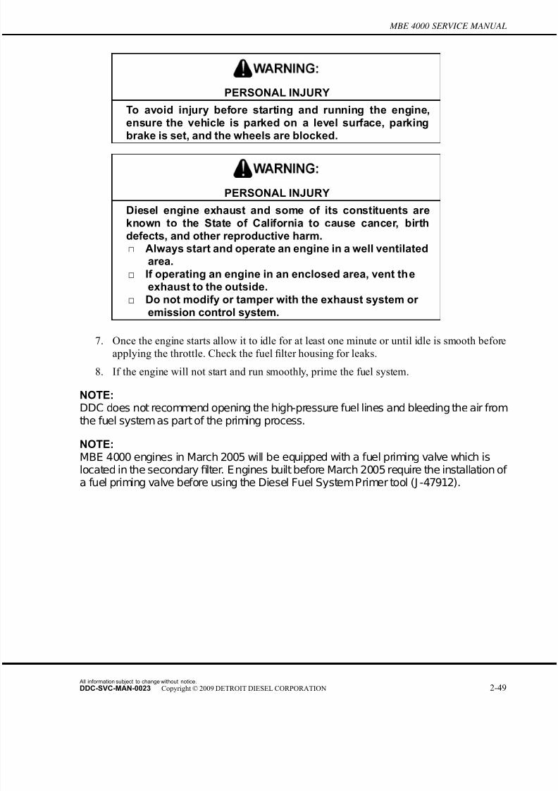
7/22/2019 Manual Mbe 4000 Taller
http://slidepdf.com/reader/full/manual-mbe-4000-taller 289/630
7/22/2019 Manual Mbe 4000 Taller
http://slidepdf.com/reader/full/manual-mbe-4000-taller 290/630
2.10 FUEL FILTER HOUSING
2.10 FUEL FILTER HOUSING
Perform the following procedures for removal and installation of the fuel filter housing.
2.10.1 Fuel Filter Housing Removal
Remove the fuel filter housing as follows:
FIRE
To avoid injury from fire, keep all potential ignition sourcesaway from diesel fuel, including open flames, sparks, andelectrical resistance heating elements. Do not smoke whenrefueling.
1. Disconnect the batteries.
2. Open the fuel tank fill cap to release pressur e in the fuel system. Replace and tighten
the cap.
3. Using a 36-mm socket, unscrew the cap on the fuel filter. Lift both the cap and the filter
element a short distance above the filter housing. See Figure 2-36 for non-EGR engines
All information subject to change without notice.
2-50 DDC-SVC-MAN-0023 Copyright © 2009 DETROIT DIESEL CORPORATION

7/22/2019 Manual Mbe 4000 Taller
http://slidepdf.com/reader/full/manual-mbe-4000-taller 291/630
MBE 4000 SERVICE MANUAL
or Figure 2-37 for EGR engines. Allow the fuel to drain off the filter into the housing
before removing.
1. Fuel Filter Housing Mounting Bracket 9. Seal Ring
2. Fuel Filter Housing 10. Banjo Fitting
3. Filter Element 11. Fuel Delivery Line
4. O-ring 12. Banjo Bolt
5. Fuel Filter Cap 13. Fuel Return Line
6. Banjo Bolt 14. Fuel Drain Line
7. Priming Nipple Valve 15. Bolts
8. Dust Cover 16. Bolts
Figure 2-36 Non-EGR Engine Fuel Filter Housing
All information subject to change without notice.
DDC-SVC-MAN-0023 Copyright © 2009 DETROIT DIESEL CORPORATION 2-51

7/22/2019 Manual Mbe 4000 Taller
http://slidepdf.com/reader/full/manual-mbe-4000-taller 292/630
2.10 FUEL FILTER HOUSING
4. Remove the priming valve assembly or banjo bolt and seal rings from the delivery line on
the filter housing. Mark both sides of the connection with a paint pen. Discard the se al
rings. See Figure 2-36 for non-EGR engines or Figure 2-37 for EGR engines.
1. Seal Ring 9. Fuel Filter Housing
2. Banjo Bolt 10. F ilter Element
3. Fuel Return Line 11. O-ring
4. Banjo Fitting 12. Fuel Filter Cap
5. Fuel Delivery Line 13. Bracket Mounting Bolts
6. Banjo Bolt 14. Fuel Filter Housing Mounting Bracket
7. Priming Nipple Valve 15. Fuel Filter Housing-to-Bracket Mounting Bolts
8. Dust Cover 16. Fuel Drain Line
Figure 2-37 EGR Engine Fuel Filter Housing
All information subject to change without notice.
2-52 DDC-SVC-MAN-0023 Copyright © 2009 DETROIT DIESEL CORPORATION
7/22/2019 Manual Mbe 4000 Taller
http://slidepdf.com/reader/full/manual-mbe-4000-taller 293/630
MBE 4000 SERVICE MANUAL
NOTE:MBE 4000 engines built in March 2005 will be equipped with a fuel priming valve whichis located in secondaryfilter. Engines built before March 2005 require the installation of afuel priming valve before using the Diesel Fuel SystemPrimer tool (J -47912).
5. Disconnect the fuel return line from the filter housing. Mark both sides of the connection
with a paint pen. Discard the seal rings.
NOTE:In a suitable container, catch any fuel that runs out of the filter housing or fuel return line.
6. Remove the drain line from the filter housing. Mark both sides of each connection with a
paint pen. Discard the seal rings.
NOTE:In a suitable container, catch any fuel that runs out of the filter housing or fuel lines.
7. Remove the two bolts attaching the filter housing to the mounting bracket.
8. Remove the filter housing from the engine.
9. Clean the fuel filter cap. Discard the filter element.
2.10.2 Fuel Filter Housing Installation
Install the fuel filter housing as follows:
1. For non-EGR engines install the fuel filter housing on the mounting bracket. Tighten the
mounting bolts to 25 N·m (18 lb·ft). For EGR engines install the fuel filter housing on the
mounting bracket. Tighten the mounting bolts to 60 N·m (44 lb·ft). See Figure 2-36 for
non-EGR engines or Figure 2-37 for EGR engines.2. Install the drain line, as removed. Install new seal rings on the banjo fitting. Tighten
the banjo bolt to 40–50 N·m (30–37 lb·ft).
3. Install the delivery line, as removed. Install a new seal rings on the priming valve or banjo
bolt. Tighten the banjo bolt to 40–50 N·m (30–37 lb·ft). If removed, install priming nipple
valve and torque to 15–16 N·m (11–12 lb·ft).
4. Install the return line, as removed. Install new seal rings on the banjo fitting. Tighten
the banjo bolt to 40–50 N·m (30–37 lb·ft).
5. Install a new filter element. Refer to section 2.9.2.
All information subject to change without notice.
DDC-SVC-MAN-0023 Copyright © 2009 DETROIT DIESEL CORPORATION 2-53

7/22/2019 Manual Mbe 4000 Taller
http://slidepdf.com/reader/full/manual-mbe-4000-taller 294/630
2.11 FUEL FILTER BRACKET
2.11 FUEL FILTER BRACKET
The removal and installation procedures remain the same for the non-EGR and EGR fuel filter
assembly; however, because of the fuel filter's new location on an EGR engine, there are modified
mounting bracket changes.
2.11.1 Non-EGR Fuel Filter Bracket Removal
Remove the Non-EGR fuel filter bracket as follows:
PERSONAL INJURY
To avoid injury from the sudden release of a high-pressurehose connection, wear a face shield or goggles.
1. Remove the fuel filter housing from the mounting bracket. Refer to section 2.10.1.
2. Remove the two filter bracket mounting bolts from bracket and block and remove the
filter bracket. See Figure 2-38.
1. Fuel Filter Housing Mounting Bracket 2. Bolts
Figure 2-38 Non-EGR Fuel Filter Bracket
All information subject to change without notice.
2-54 DDC-SVC-MAN-0023 Copyright © 2009 DETROIT DIESEL CORPORATION

7/22/2019 Manual Mbe 4000 Taller
http://slidepdf.com/reader/full/manual-mbe-4000-taller 295/630
MBE 4000 SERVICE MANUAL
2.11.2 Non-EGR Fuel Filter Bracket Installation
Install the non-EGR fuel filter bracket as follows:
1. Install the fuel filter bracket to the block using two fuel filter bracket mounting bolts.
Torque bolts to 50 N·m (37 lb·ft). See Figure 2-38.
2. Install the fuel filter housing to the mounting bracket. Refer to section 2.10.2.
2.11.3 EGR Fuel Filter Bracket Removal
Remove the EGR fuel filter bracket as follows:
1. Remove the fuel filter housing from the mounting bracket. Refer to section 2.10.1.
1. Fuel Filter-to-Bracket Mounting Bolts 3. Fuel Filter Bracket Mounting Bolts
2. Fuel Filter Mounting Bracket
Figure 2-39 EGR Fuel Filter Bracket
2. Remove the three filter bracket mounting bolts from bracket and block and remove the
filter bracket. See figure 2-39.
2.11.4 EGR Fuel Filter Bracket Installation
Install the EGR fuel filter bracket as follows:
1. Install the fuel filter bracket to the block using the three 8 mm x 90 mm fuel filter bracket
mounting bolts. Torque the bolts to 25 N·m (18 lb·ft). See figure 2-39.
All information subject to change without notice.
DDC-SVC-MAN-0023 Copyright © 2009 DETROIT DIESEL CORPORATION 2-55
7/22/2019 Manual Mbe 4000 Taller
http://slidepdf.com/reader/full/manual-mbe-4000-taller 296/630
2.11 FUEL FILTER BRACKET
2. Install the fuel filter housing to the mounting bracket. Refer to section 2.10.2.
All information subject to change without notice.
2-56 DDC-SVC-MAN-0023 Copyright © 2009 DETROIT DIESEL CORPORATION

7/22/2019 Manual Mbe 4000 Taller
http://slidepdf.com/reader/full/manual-mbe-4000-taller 297/630
MBE 4000 SERVICE MANUAL
2.12 FUEL PUMP
Perform the following procedures for removal and installation of the fuel pump.
2.12.1 Fuel Pump Removal
Remove the fuel pump as follows:
FIRE
To avoid injury from fire, keep all potential ignition sourcesaway from diesel fuel, including open flames, sparks, andelectrical resistance heating elements. Do not smoke whenrefueling.
1. Disconnect the batteries.
2. Open the fuel tank fill cap to release the pressure in the fuel system. Replace and tighten
the cap.
All information subject to change without notice.
DDC-SVC-MAN-0023 Copyright © 2009 DETROIT DIESEL CORPORATION 2-57

7/22/2019 Manual Mbe 4000 Taller
http://slidepdf.com/reader/full/manual-mbe-4000-taller 298/630
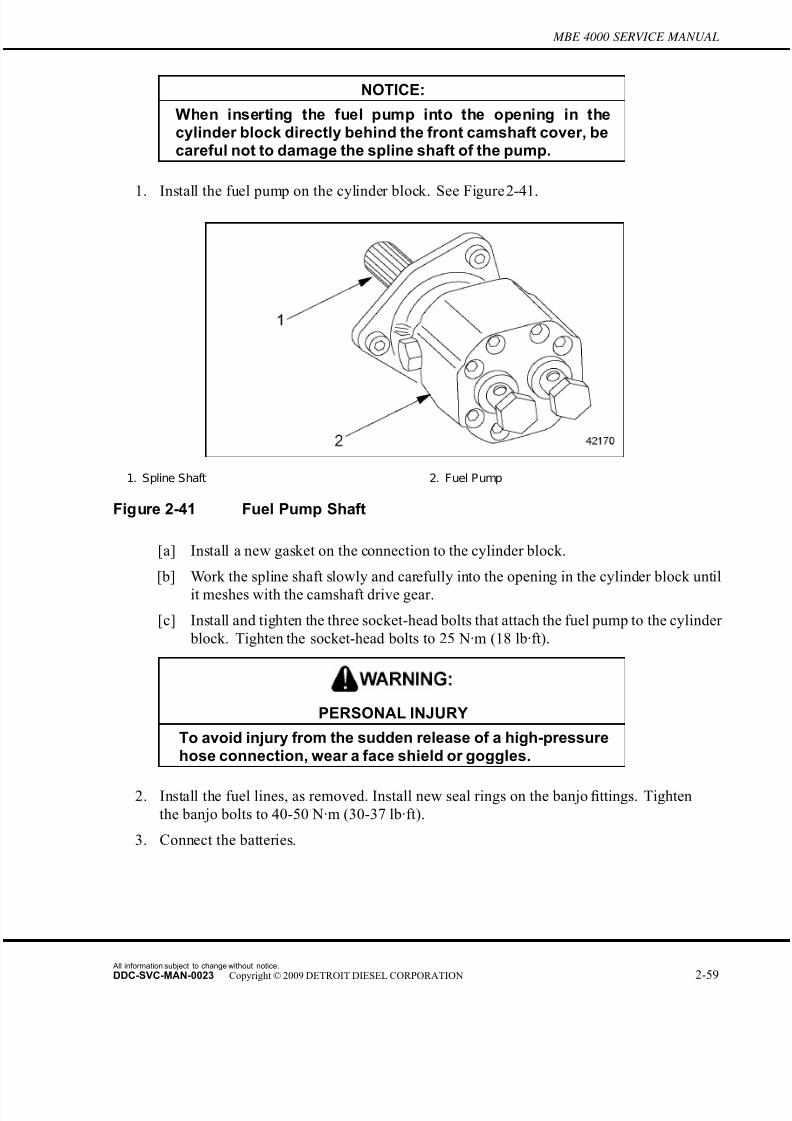
7/22/2019 Manual Mbe 4000 Taller
http://slidepdf.com/reader/full/manual-mbe-4000-taller 299/630
MBE 4000 SERVICE MANUAL
NOTICE:
When inserting the fuel pump into the opening in thecylinder block directly behind the front camshaft cover, becareful not to damage the spline shaft of the pump.
1. Install the fuel pump on the cylinder block. See Figure 2-41.
1. Spline Shaft 2. Fuel Pump
Figure 2-41 Fuel Pump Shaft
[a] Install a new gasket on the connection to the cylinder block.
[b] Work the spline shaft slowly and carefully into the opening in the cylinder block until
it meshes with the camshaft drive gear.
[c] Install and tighten the three socket-head bolts that attach the fuel pump to the cylinder
block. Tighten the socket-head bolts to 25 N·m (18 lb·ft).
PERSONAL INJURY
To avoid injury fr om the sudden release of a high-pressurehose connection, wear a face shield or goggles.
2. Install the fuel lines, as removed. Install new seal rings on the banjo fittings. Tighten
the banjo bolts to 40-50 N·m (30-37 lb·ft).
3. Connect the batteries.
All information subject to change without notice.
DDC-SVC-MAN-0023 Copyright © 2009 DETROIT DIESEL CORPORATION 2-59

7/22/2019 Manual Mbe 4000 Taller
http://slidepdf.com/reader/full/manual-mbe-4000-taller 300/630
2.12 FUEL PUMP
PERSONAL INJURY
Diesel engine exhaust and some of its constituents areknown to the State of California to cause cancer, birth
defects, and other reproductive harm.□ Always start and operate an engine in a well ventilated
area.□ If operating an engine in an enclosed area, vent the
exhaust to the outside.□ Do not modify or tamper with the exhaust system or
emission control system.
4. Prime the fuel system.
5. With the engine running, check the fuel pump and the rest of the fuel system for leaks.
Shut down the engine.
All information subject to change without notice.
2-60 DDC-SVC-MAN-0023 Copyright © 2009 DETROIT DIESEL CORPORATION
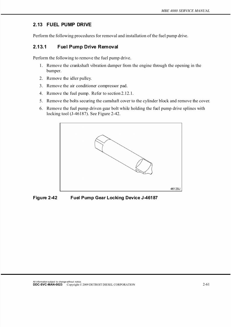
7/22/2019 Manual Mbe 4000 Taller
http://slidepdf.com/reader/full/manual-mbe-4000-taller 301/630
MBE 4000 SERVICE MANUAL
2.13 FUEL PUMP DRIVE
Perform the following procedures for removal and installation of the fuel pump drive.
2.13.1 Fuel Pump Drive Removal
Perform the following to remove the fuel pump drive.
1. Remove the crankshaft vibration damper from the engine through the opening in the
bumper.
2. Remove the idler pulley.
3. Remove the air conditioner compressor pad.
4. Remove the fuel pump. Refer to section 2.12.1.
5. Remove the bolts securing the camshaft cover to the cylinder block and remove the cover.
6. Remove the fuel pump driven gear bolt while holding the fuel pump drive splines with
locking tool (J-46187). See Figure 2-42.
Figure 2-42 Fuel Pump Gear Locking Device J-46187
All information subject to change without notice.
DDC-SVC-MAN-0023 Copyright © 2009 DETROIT DIESEL CORPORATION 2-61
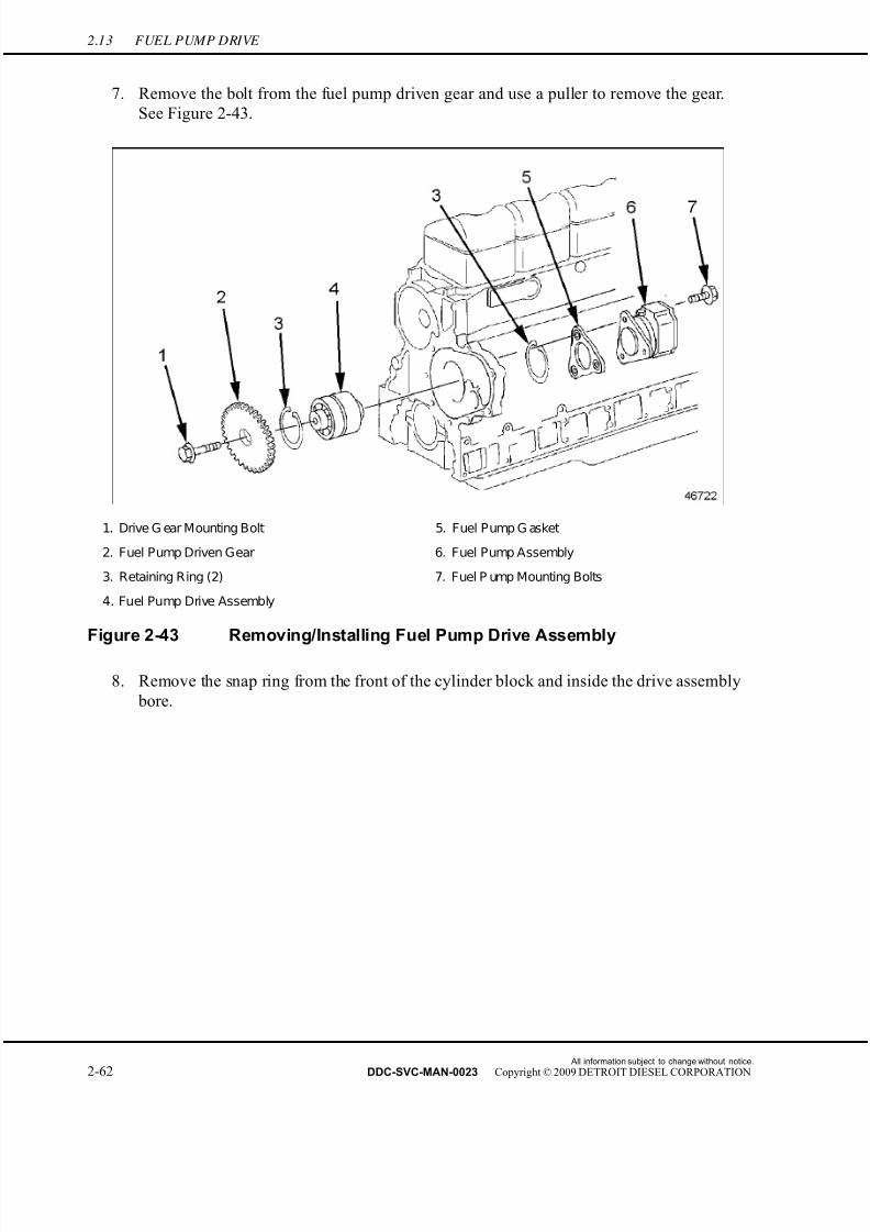
7/22/2019 Manual Mbe 4000 Taller
http://slidepdf.com/reader/full/manual-mbe-4000-taller 302/630
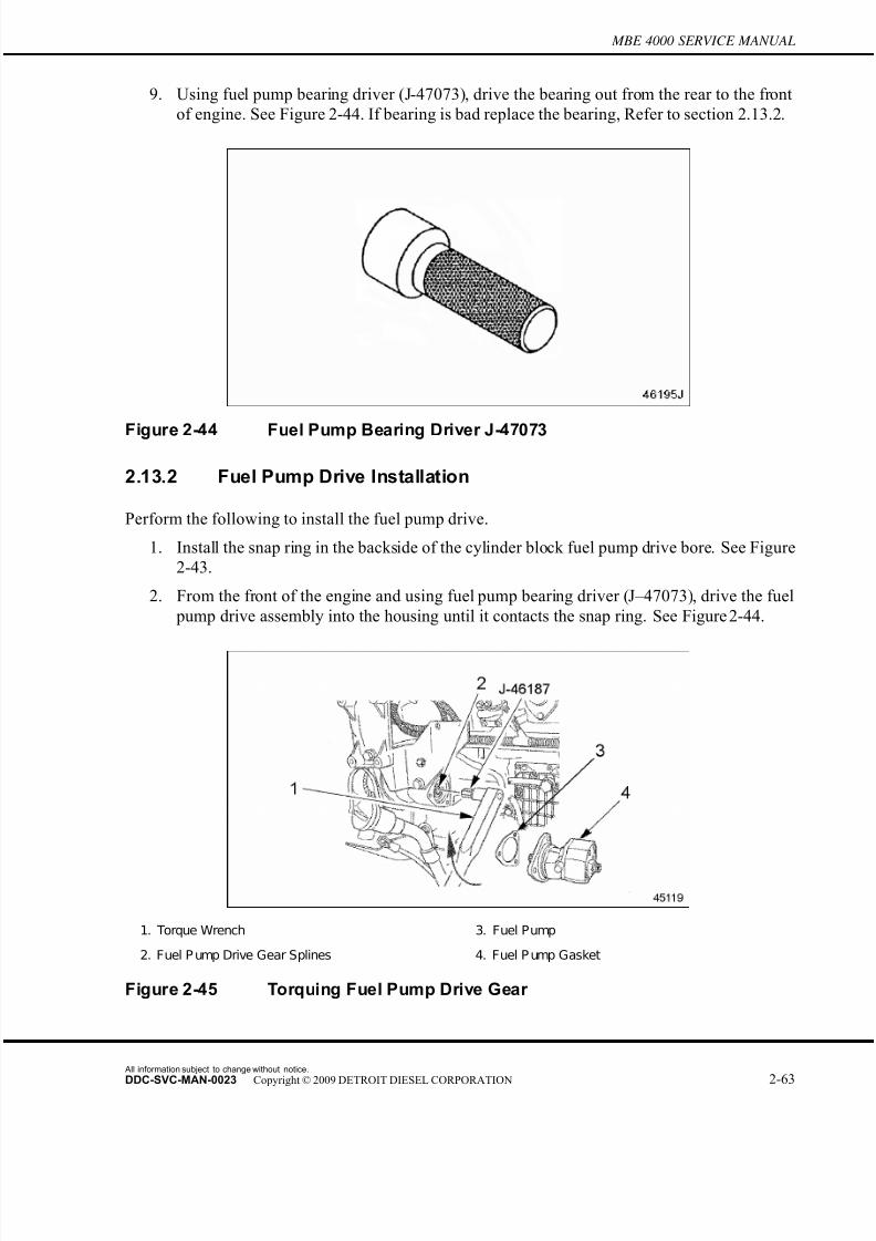
7/22/2019 Manual Mbe 4000 Taller
http://slidepdf.com/reader/full/manual-mbe-4000-taller 303/630
MBE 4000 SERVICE MANUAL
9. Using fuel pump bearing driver (J-47073), drive the bearing out from the rear to the front
of engine. See Figure 2-44. If bearing is bad replace the bearing, Refer to section 2.13.2.
Figure 2-44 Fuel Pump Bearing Driver J-47073
2.13.2 Fuel Pump Drive Installation
Perform the following to install the fuel pump drive.
1. Install the snap ring in the backside of the cylinder block fuel pump drive bore. See Figure
2-43.
2. From the front of the engine and using fuel pump bearing driver (J–47073), drive the fuel
pump drive assembly into the housing until it contacts the snap ring. See Figure 2-44.
1. Torque Wrench 3. Fuel Pump
2. Fuel P ump Drive Gear Splines 4. Fuel P ump Gasket
Figure 2-45 Torquing Fuel Pump Drive Gear
All information subject to change without notice.
DDC-SVC-MAN-0023 Copyright © 2009 DETROIT DIESEL CORPORATION 2-63
7/22/2019 Manual Mbe 4000 Taller
http://slidepdf.com/reader/full/manual-mbe-4000-taller 304/630
2.13 FUEL PUMP DRIVE
3. Install the snap ring in the front side of the cylinder block fuel pump drive bore to secure
the fuel pump drive. See Figure 2-43.
4. Install fuel pump driven gear and bolt. Apply Loctite® 271 sealant to the bolt threads
and install gear and bolt. Install the fuel pump gear locking device (J–46187) to the fuel
pump drive splines and secure the shaft from turning while torquing bolt. See Figure
2-45 and Figure 2-42.
5. Torque the driven gear bolt to 35 N·m (26 lb·ft).
6. Install the camshaft cover. Torque the bolts to 50 N·m (37 lb·ft).
7. Install the fuel pump and a new fuel pump gasket. Refer to section 2.12.2.
8. Install camshaft front cover and secure with eight bolts. Torque the bolts to 50 N·m (37
lb·ft).
9. Install the air conditioner compressor pad.
10. Install idler pulley.
11. Install the alternator and electrical connections.
12. Install the crankshaft vibration damper on the crankshaft.
All information subject to change without notice.
2-64 DDC-SVC-MAN-0023 Copyright © 2009 DETROIT DIESEL CORPORATION

7/22/2019 Manual Mbe 4000 Taller
http://slidepdf.com/reader/full/manual-mbe-4000-taller 305/630
MBE 4000 SERVICE MANUAL
2.14 FUEL SYSTEM INSPECTION
Perform the following steps to inspect the fuel system for damage:
PERSONAL INJURY
To avoid injury from penetrating fluids, do not put your hands in front of fluid under pressure. Fluids under pressure can penetrate skin and clothing.
FIRE
To avoid injury from fire, keep all potential ignition sourcesaway from diesel fuel, including open flames, sparks, andelectrical resistance heating elements. Do not smoke whenrefueling.
NOTE:For additional safety precautions, refer to the General Information section of the MBE4000 Service Manual (6SE412).
1. Check fuel delivery lines looking for deformation or bent lines, creating restriction and/or
obstruction of the flow.
2. Check suction lines and connections looking for damage or under torque, allowing air
to enter the fuel system.
3. Check the fuel tank installation. Look for bent/blocked lines, and leaks.
4. Check high-pressure lines for leaks. Look for connector nut leaks at the unit pump
and at the transfer tube on the cylinder head. In the event of leaks, disassemble and
inspect the high-pressure lines/transfer tube. For proper torque specifications, see those
listed in Table 2-2.
Component Torque – N·m (lb·ft)
Thrust Bolt 45 (33)
High Pressure Line Nuts 30 (22)
Table 2-2 Torque Specifications for Fuel Line Nuts
5. Perform a fuel pressure test. Refer to section 2.14.1.
All information subject to change without notice.
DDC-SVC-MAN-0023 Copyright © 2009 DETROIT DIESEL CORPORATION 2-65
7/22/2019 Manual Mbe 4000 Taller
http://slidepdf.com/reader/full/manual-mbe-4000-taller 306/630
2.14 FUEL SYSTEM INSPECTION
2.14.1 Performing a Fuel Pressure Test
Perform the following steps to conduct a fuel pressure test:
1. Install the pressure gauge on the fuel system. There are two possible setups for this
installation. Setup 1 has the gauge installed after the fuel filter. See Figure 2-46. Setup 2
has the gauge installed before the fuel filter. See Figure 2-47.
1. Fitting 4. Fuel Outlet Line
2. Fuel Filter Housing 5. Unit Pump
3. Mechanical Gauge
Figure 2-46 Gauge Installation – After the Fuel Filter
1. Fuel Pump 4. Fuel Outlet Line
2. Fitting 5. Mechanical Gauge
3. Fuel Filter Housing
Figure 2-47 Gauge Installation – Before the Fuel Filter
All information subject to change without notice.
2-66 DDC-SVC-MAN-0023 Copyright © 2009 DETROIT DIESEL CORPORATION
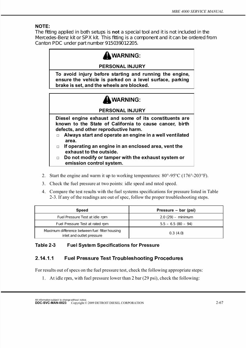
7/22/2019 Manual Mbe 4000 Taller
http://slidepdf.com/reader/full/manual-mbe-4000-taller 307/630
MBE 4000 SERVICE MANUAL
NOTE: The fitting applied in both setups is not a special tool and it is not included in theMercedes-Benz kit or SP X kit. This fitting is a component and it can be ordered fromCanton PDC under part number 915039012205.
PERSONAL INJURY
To avoid injury before starting and running the engine,ensure the vehicle is parked on a level surface, parkingbrake is set, and the wheels are blocked.
PERSONAL INJURY
Diesel engine exhaust and some of its constituents are
known to the State of California to cause cancer, birthdefects, and other reproductive harm.□ Always start and operate an engine in a well ventilated
area.□ If operating an engine in an enclosed area, vent the
exhaust to the outside.□ Do not modify or tamper with the exhaust system or
emission control system.
2. Start the engine and warm it up to working temperatures: 80°-95°C (176°-203°F).
3. Check the fuel pressure at two points: idle speed and rated speed.
4. Compare the test results with the fuel systems specifications for pressure listed in Table
2-3. If any of the readings are out of spec, follow the proper troubleshooting steps.
Speed Pressure – bar (psi)
Fuel Pressure Test at idle rpm 2.0 (29) – minimum
Fuel Pressure Test at rated rpm 5.5 – 6.5 (80 – 94)
Maximum difference between fuel filter housing
inlet and outlet pressure0.3 (4.0)
Table 2-3 Fuel System Specifications for Pressure
2.14.1.1 Fuel Pressure Test Troubleshooting Procedures
For results out of specs on the fuel pressure test, check the following appropriate steps:
1. At idle rpm, with fuel pressure lower than 2 bar (29 psi), check the following:
All information subject to change without notice.
DDC-SVC-MAN-0023 Copyright © 2009 DETROIT DIESEL CORPORATION 2-67
7/22/2019 Manual Mbe 4000 Taller
http://slidepdf.com/reader/full/manual-mbe-4000-taller 308/630
2.14 FUEL SYSTEM INSPECTION
□ Check the pressure valve at the end of the fuel gallery. Look for opening pressure 2
bar (29 psi).
□ Check the fuel pump assembly (bearing and/or driven gear).
□ Check to see if the fuel system is drawing air.
2. At rated rpm, for fuel pressure lower than 5.5 bar (80 psi), check the following:
□ Check the water separator filter condition.
□ Check for restriction at the check valve on the DDEC-ECU heat exchange plate.□ Check the main fuel filter condition, looking for saturation or any damaged seal
allowing flow of fuel from the pressure side to the return side.
□ Check for leaks at the suction lines from the tank.
□ Check the fuel pump assembly (bearing and/or driven gear).
□ Look for leaks and/or a damaged fuel pump.
□ Check for restriction at the check valve on the fuel filter return line to tank.
3. At rated rpm, for fuel pressure higher than 6.5 bar (94 psi), check the following:
□ Check the return line and injector spill line, looking for restrictions or bent lines.
□ Check the fuel pressure valve for a blocked or restricted regulator orifice.
2.14.2 Performing a Fuel System Test using minidiag2
To perform a fuel system test using minidiag2, perform the f ollowing steps:
All information subject to change without notice.
2-68 DDC-SVC-MAN-0023 Copyright © 2009 DETROIT DIESEL CORPORATION
7/22/2019 Manual Mbe 4000 Taller
http://slidepdf.com/reader/full/manual-mbe-4000-taller 309/630
MBE 4000 SERVICE MANUAL
PERSONAL INJURY
To avoid injury when working near or on an operatingengine, remove loose items of clothing and jewelry. Tie
back or contain long hair that could be caught in anymoving part causing injury.
PERSONAL INJURY
Diesel engine exhaust and some of its constituents areknown to the State of California to cause cancer, birthdefects, and other reproductive harm.□ Always start and operate an engine in a well ventilated
area.□ If operating an engine in an enclosed area, vent the
exhaust to the outside.□ Do not modify or tamper with the exhaust system or
emission control system.
NOTE:Before running the test, warm the engine to normal operating temperatures: 80°-95°C(176°-203°F).
1. Plug your minidiag2 into the truck diagnostic connector and follow the instructions in the
minidiag2 Supplement Manual to connect to the VCU/DDEC-ECU system.
2. After establishing the connection with the truck, choose option 4 – Routines.
3. Under Routines section, select option 4 – Idle Smoothly Balance.
4. Check each cylinder value for this routine and compare your results with the
troubleshooting and proceed as described for any results out of spec. Refer to section
2.14.2.1.
5. Still connected to truck, look for option 5 – Impact Time Delay, under the Routines section.
6. Select it and check each cylinder value for this routine and compare your results with the
troubleshooting and proceed as described for results out of spec.
2.14.2.1 Idle Smoothly Balance Troubleshooting
This test measures the percentage of fuel delivery for each cylinder in order to maintain a smooth
operation at idle. Operational range for this test: from -3% (negative) to 3% (positive).
Identify the cylinder with the biggest absolute value – highest positive or lowest negative. The
troubleshooting steps for both conditions are:
All information subject to change without notice.
DDC-SVC-MAN-0023 Copyright © 2009 DETROIT DIESEL CORPORATION 2-69
7/22/2019 Manual Mbe 4000 Taller
http://slidepdf.com/reader/full/manual-mbe-4000-taller 310/630
2.14 FUEL SYSTEM INSPECTION
For Highest Positive:
1. Check torque at all the thrust bolts (45 N·m [33 lb·ft]). Run the test again. If the r esults are
out of operational range, proceed to next step.
2. Find the cylinder with the result closest to zero. Swap the injector nozzle holder and the
transfer tube between this cylinder and the cylinder with the highest result. Run the test
again. If the highest result follows the injector nozzle holder, replace the nozzle holder.If not, proceed to the next step.
NOTE:After removing the injector nozzle holders and transfer tubes, check the coupling areabetween both components and the seal rings. If any defect or damage is found, replacethe damaged parts.
3. Return both injector nozzle holders and transfer tubes to their original positions and run
the impact delay time and compression test routines.
For Lowest Negative:
1. Check torque at all the thrust bolts (45 N·m [33 lb·ft]). Run the test again. If the results
are out of the operational range, proceed to the next step.
2. Find the cylinder with the lowest result, r emove the injector nozzle holder and check the
opening pressure. If the pressure is lower than the minimum spec (275 bar [3989 psi]),
replace the injector nozzle holder. If the pressure is within the spec, proceed to the next
step.
3. Run a compression test using minidiag2, ProLink reader, or DDDL 5.0 (refer to the
Diagnostic Tool Manual for instructions to run this test). The readings must be 75% or
higher. For readings lower than 75%, remove the oil pan and cylinder head and check
for damaged components.
2.14.2.2 Impact Delay Time Troubleshooting
This test measures the reaction time of the unit pumps. The operation range is from 1.2 to 2.1
milliseconds. Perform the following troubleshooting procedure for values out of the operating
range:
1. Check the engine harness from the DDEC-ECU to the suspected unit pump – connectors
and wire. Look for bad or loose connections and broken wires. If there are none, proceed
to the next step.
2. Swap the suspect unit pump with one operating properly and run the test again.Refer to section2.1.1 for unit pump removal and refer to section 2.1.3 for unit pump
installation. If the condition follows the unit pump, replace the unit pump.
2.14.2.3 Checking the Fuel Pump Driven Gear Bolt Torque
This procedure describes how to check the fuel pump driven gear bolt torque. Insuf ficient torque
on the bolt will impact engine performance.
All information subject to change without notice.
2-70 DDC-SVC-MAN-0023 Copyright © 2009 DETROIT DIESEL CORPORATION
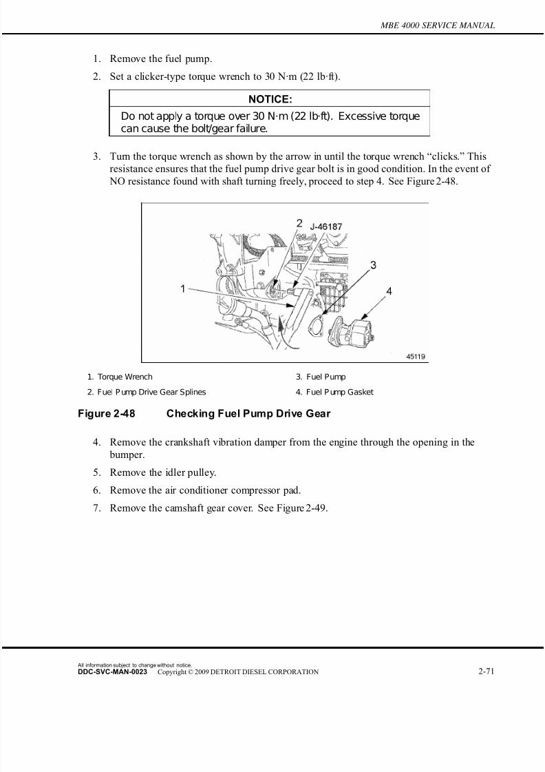
7/22/2019 Manual Mbe 4000 Taller
http://slidepdf.com/reader/full/manual-mbe-4000-taller 311/630
MBE 4000 SERVICE MANUAL
1. Remove the fuel pump.
2. Set a clicker-type torque wrench to 30 N·m (22 lb·ft).
NOTICE:
Do not apply a torque over 30 N·m (22 lb·ft). Excessive torquecan cause the bolt/gear failure.
3. Turn the torque wrench as shown by the arrow in until the torque wrench “clicks.” This
resistance ensures that the fuel pump drive gear bolt is in good condition. In the event of
NO resistance found with shaft turning freely, proceed to step 4. See Figure 2-48.
1. Torque Wrench 3. Fuel Pump
2. Fuel P ump Drive Gear Splines 4. Fuel P ump Gasket
Figure 2-48 Checking Fuel Pump Drive Gear
4. Remove the crankshaft vibration damper from the engine through the opening in the
bumper.
5. Remove the idler pulley.
6. Remove the air conditioner compressor pad.
7. Remove the camshaft gear cover. See Figure 2-49.
All information subject to change without notice.
DDC-SVC-MAN-0023 Copyright © 2009 DETROIT DIESEL CORPORATION 2-71
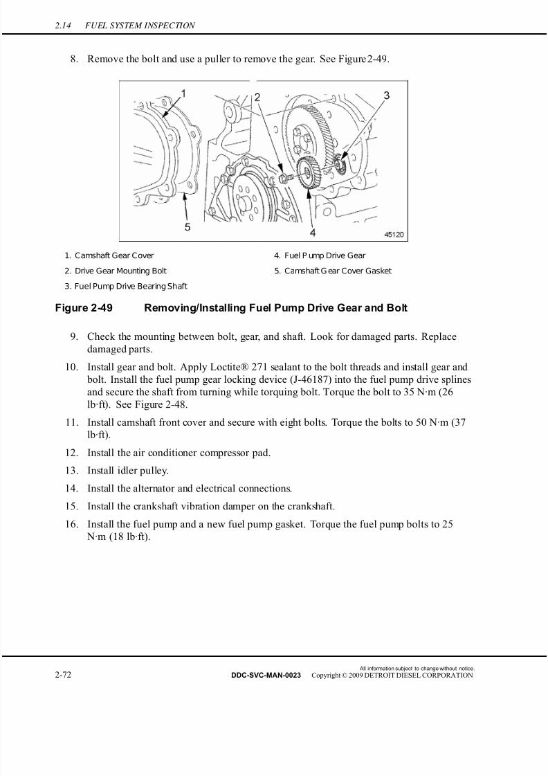
7/22/2019 Manual Mbe 4000 Taller
http://slidepdf.com/reader/full/manual-mbe-4000-taller 312/630
2.14 FUEL SYSTEM INSPECTION
8. Remove the bolt and use a puller to remove the gear. See Figure 2-49.
1. Camshaft Gear Cover 4. Fuel P ump Drive Gear
2. Drive Gear Mounting Bolt 5. Camshaft G ear Cover Gasket
3. Fuel Pump Drive Bearing Shaft
Figure 2-49 Removing/Installing Fuel Pump Drive Gear and Bolt
9. Check the mounting between bolt, gear, and shaft. Look for damaged parts. Replace
damaged parts.
10. Install gear and bolt. Apply Loctite® 271 sealant to the bolt threads and install gear and
bolt. Install the fuel pump gear locking device (J-46187) into the fuel pump drive splines
and secure the shaft from turning while torquing bolt. Torque the bolt to 35 N·m (26
lb·ft). See Figure 2-48.11. Install camshaft front cover and secure with eight bolts. Torque the bolts to 50 N·m (37
lb·ft).
12. Install the air conditioner compressor pad.
13. Install idler pulley.
14. Install the alternator and electrical connections.
15. Install the crankshaft vibration damper on the crankshaft.
16. Install the fuel pump and a new fuel pump gasket. Torque the fuel pump bolts to 25
N·m (18 lb·ft).
All information subject to change without notice.
2-72 DDC-SVC-MAN-0023 Copyright © 2009 DETROIT DIESEL CORPORATION
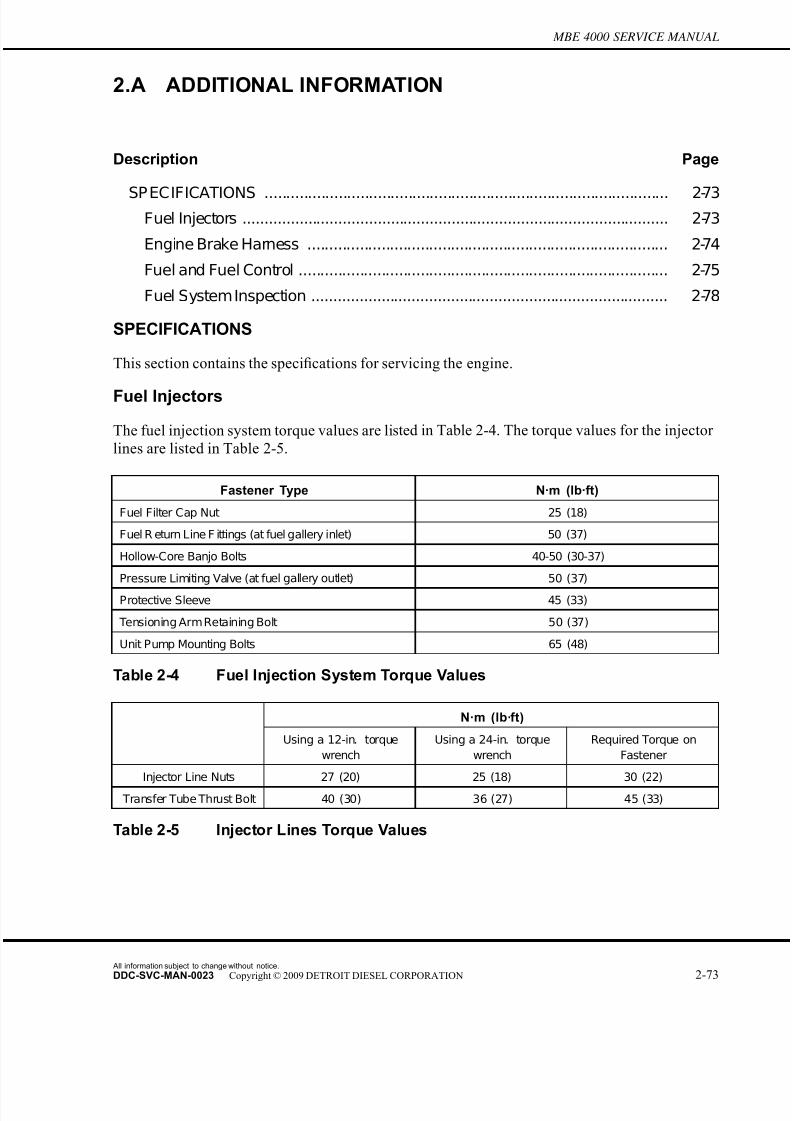
7/22/2019 Manual Mbe 4000 Taller
http://slidepdf.com/reader/full/manual-mbe-4000-taller 313/630
MBE 4000 SERVICE MANUAL
2.A ADDITIONAL INFORMATION
Description Page
SP ECIFICATIONS ............................................................................................. 2-73Fuel Injectors .................................................................................................. 2-73
Engine Brake Harness ................................................................................... 2-74
Fuel and Fuel Control ..................................................................................... 2-75
Fuel System Inspection .................................................................................. 2-78
SPECIFICATIONS
This section contains the specifications for servicing the engine.
Fuel Injectors
The fuel injection system torque values are listed in Table 2-4. The torque values for the injector
lines are listed in Table 2-5.
Fastener Type N·m (lb·ft)
Fuel Filter Cap Nut 25 (18)
Fuel R eturn Line F ittings (at fuel gallery inlet) 50 (37)
Hollow-Core Banjo Bolts 40-50 (30-37)
Pressure Limiting Valve (at fuel gallery outlet) 50 (37)
Protective Sleeve 45 (33)
Tensioning Arm Retaining Bolt 50 (37)
Unit Pump Mounting Bolts 65 (48)
Table 2-4 Fuel Injection System Torque Values
N·m (lb·ft)
Using a 12-in. torque
wrench
Using a 24-in. torque
wrench
Required Torque on
Fastener
Injector Line Nuts 27 (20) 25 (18) 30 (22)
Transfer Tube Thrust Bolt 40 (30) 36 (27) 45 (33)
Table 2-5 Injector Lines Torque Values
All information subject to change without notice.
DDC-SVC-MAN-0023 Copyright © 2009 DETROIT DIESEL CORPORATION 2-73

7/22/2019 Manual Mbe 4000 Taller
http://slidepdf.com/reader/full/manual-mbe-4000-taller 314/630
Engine Brake Harness
The former 8-pin Engine Harness Connector is identified with part number A460 150 00 33, and
it is used in the engines that have one solenoid air valve for the engine brakes. Beginning with the
engine serial number 739080, these current engines will have an 8-pin Engine Harness Connector
with part number A460 150 01 33. The changes in the harness connections between the former
and current 8-pin harness connector are Listed in Table 2-6 and listed in Table 2-7.
Description 8-P in E ngine Harness C onnector DDE C-E CU 55-P in C onnector
Fan Control 1, switch to Bat- (PV3) A 41
Fan Control 2, switch to Bat- (PV4) B 43
Output Ground (PV) C 11
Fan and Wastegate/E-Flap Voltage
Supply (PV1, 3, 4)D 12
Exhaust Flap/Wastegate Control,
switch to Bat- (PV1)E 51
Fan and Wastegate/E-Flap VoltageSupply (PV1, 3, 4)
F 12
Turbo Brake Control, switch to Bat-
(PV6)G 40
Turbo Brake Voltage Supply (PV6) H 42
Table 2-6 Former Harness Connector A460 150 00 33
Description 8-P in E ngine Harness C onnector DDE C-E CU 55-P in C onnector
Fan Control #1, switch to Bat- (PV3) A 41
Fan Control #2, switch to Bat- (PV4) B 43
Compression Brake Control, switch
to Bat- (PV2)C 50
Fan and Wastegate/E-Flap Voltage
Supply (PV1, 3, 4)D 12
Exhaust Flap/Wastegate Control,
switch to Bat- (PV1)E 51
Compression Brake Voltage Supply
(PV2)F 52
Turbo Brake Control, switch to Bat-
(PV6)G 40
Turbo Brake Voltage Supply (PV6) H 42
Table 2-7 Current Harness Connector A460 150 01 33
All information subject to change without notice.
2-74 DDC-SVC-MAN-0023 Copyright © 2009 DETROIT DIESEL CORPORATION
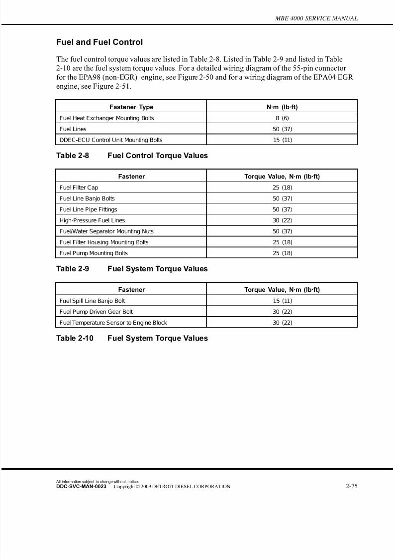
7/22/2019 Manual Mbe 4000 Taller
http://slidepdf.com/reader/full/manual-mbe-4000-taller 315/630
MBE 4000 SERVICE MANUAL
Fuel and Fuel Control
The fuel control torque values are listed in Table 2-8. Listed in Table 2-9 and listed in Table
2-10 are the fuel system torque values. For a detailed wiring diagram of the 55-pin connector
for the EPA98 (non-EGR) engine, see Figure 2-50 and for a wiring diagram of the EPA04 EGR
engine, see Figure 2-51.
Fastener Type N·m (lb·ft)
Fuel Heat Exchanger Mounting Bolts 8 (6)
Fuel Lines 50 (37)
DDEC-ECU Control Unit Mounting Bolts 15 (11)
Table 2-8 Fuel Control Torque Values
Fastener Torque Value, N·m (lb·ft)
Fuel Filter Cap 25 (18)
Fuel Line Banjo Bolts 50 (37)
Fuel Line Pipe Fittings 50 (37)
High-Pressure Fuel Lines 30 (22)
Fuel/Water Separator Mounting Nuts 50 (37)
Fuel Filter Housing Mounting Bolts 25 (18)
Fuel Pump Mounting Bolts 25 (18)
Table 2-9 Fuel System Torque Values
Fastener Torque Value, N·m (lb·ft)
Fuel Spill Line Banjo Bolt 15 (11)
Fuel Pump Driven Gear Bolt 30 (22)
Fuel Temperature Sensor to Engine Block 30 (22)
Table 2-10 Fuel System Torque Values
All information subject to change without notice.
DDC-SVC-MAN-0023 Copyright © 2009 DETROIT DIESEL CORPORATION 2-75
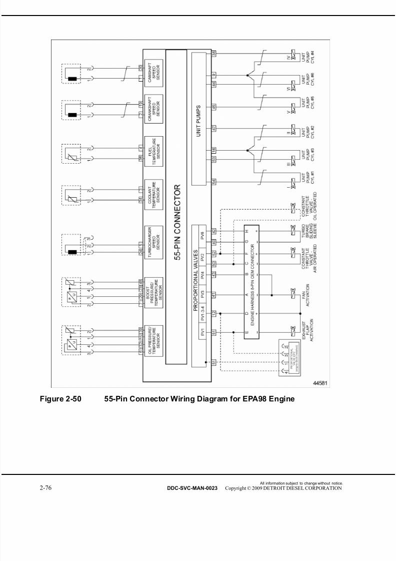
7/22/2019 Manual Mbe 4000 Taller
http://slidepdf.com/reader/full/manual-mbe-4000-taller 316/630
Figure 2-50 55-Pin Connector Wiring Diagram for EPA98 Engine
All information subject to change without notice.
2-76 DDC-SVC-MAN-0023 Copyright © 2009 DETROIT DIESEL CORPORATION

7/22/2019 Manual Mbe 4000 Taller
http://slidepdf.com/reader/full/manual-mbe-4000-taller 317/630
MBE 4000 SERVICE MANUAL
Figure 2-51 55-Pin Connector Wiring Diagram for EPA04 (EGR) Engine
All information subject to change without notice.
DDC-SVC-MAN-0023 Copyright © 2009 DETROIT DIESEL CORPORATION 2-77

7/22/2019 Manual Mbe 4000 Taller
http://slidepdf.com/reader/full/manual-mbe-4000-taller 318/630
Fuel System Inspection
The torque specifications for fuel line nuts are listed in Table 2-11. The fuel system specifications
for pressure are listed in Table 2-12.
Component Torque – N·m (lb·ft)
Transfer Tube Nut 45 (33)
High Pressure Line Nuts 30 (22)
Table 2-11 Torque Specifications for Fuel Line Nuts
Speed Pressure – bar (psi)
Fuel Pressure Test at idle rpm 2.0 (29) – minimum
Fuel Pressure Test at rated rpm 5.5 – 6.5 (80 – 94)
Maximum difference between fuel filter housing
inlet and outlet pressure0.3 (4.0)
Table 2-12 Fuel System Specifications for Pressure
All information subject to change without notice.
2-78 DDC-SVC-MAN-0023 Copyright © 2009 DETROIT DIESEL CORPORATION

7/22/2019 Manual Mbe 4000 Taller
http://slidepdf.com/reader/full/manual-mbe-4000-taller 319/630
3 LUBRICATION SYSTEM
Section Page
3.1 LUBRICATION SY STEM DESCRIPTION ................................................ 3-3
3.2 OIL PAN ................................................................................................... 3-5
3.3 PISTON OIL SP RAY NOZZLE(S) ............................................................ 3-11
3.4 CAMSHAFT LUBRICATION SP RAYER ................................................... 3-17
3.5 OIL PUMP AND SUMP PIPE ................................................................... 3-19
3.6 OIL FILTER .............................................................................................. 3-27
3.7 OIL HEAT EXCHANGER/FILTER HOUSING .......................................... 3-29
3.8 OIL PRESSURE/TEMPERATURE SENSOR ........................................... 3-34
3.A ADDITIONAL INFORMATION .................................................................. 3-37

7/22/2019 Manual Mbe 4000 Taller
http://slidepdf.com/reader/full/manual-mbe-4000-taller 320/630
All information subject to change without notice.
3-2 DDC-SVC-MAN-0023 Copyright © 2009 DETROIT DIESEL CORPORATION
7/22/2019 Manual Mbe 4000 Taller
http://slidepdf.com/reader/full/manual-mbe-4000-taller 321/630
MBE 4000 SERVICE MANUAL
3.1 LUBRICATION SYSTEM DESCRIPTION
The MBE 4000 engine features a full-flow filtered, pressurized lubricating oil system. The system
incorporates various valves and restricted orifices to optimize the oil flow. External piping and
plumbing is kept to a minimum to avoid oil leakage.
The lubricating system consists of the following components:
□ Oil pump
□ Pressure relief valve
□ Oil filter
□ Oil cooler
□ Oil level dipstick
□ Oil pan
□ Breather System
An internal tooth gear pump is mounted to the bottom rear of the engine block and direct driven
by the crankshaft at 1.06 times engine speed. The location of the oil sump pick-up tube varies
with oil pan choice.
The oil pump pulls oil from the oil pan through the pick-up tube. Oil leaving the pump is routed
through the oil cooler, then to the oil filter and bypass valve. If the oil pressure is too high, the
oil is routed through the pressure relief valve on the oil pump to the oil pan. The filtered oil is
then routed into the main oil gallery in the cylinder block. From there, the oil is distributed to the
crankshaft, rods, pistons and then to the camshaft bearings. Oil spray nozzles are installed in the
block, which provide a continuous spray of oil to the underside of the pistons. From the camshaft
bearings, oil is routed to oil passages in the cylinder head, which deliver oil to the valve train
components and rocker arm pedestals. Some oil is delivered to the rear of the camshaft to help
control camshaft end play. A camshaft bearing galley supplies oil for the spray nozzles which
provides a continuous supply of oil to the camshaft lobes, valve tappets, and the unit pump rollers.
The oil drains from the cylinder head to the oil pan. Oil for gear train components at the front of the engine is fed through drilled holes out of the main gallery. The turbochargers oil supply is
taken from the oil galley circuit. Oil from the turbocharger returns to the crankcase via an external
tube. A mechanical oil separator pulls any oil droplets out of the crankcase vapor and returns the
oil back into the oil pan. The clean air is then returned to the atmosphere. See Figure 3-1.
All information subject to change without notice.
DDC-SVC-MAN-0023 Copyright © 2009 DETROIT DIESEL CORPORATION 3-3
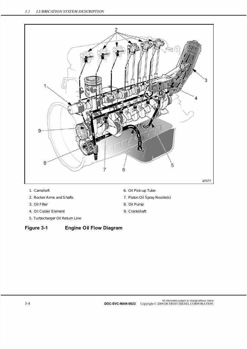
7/22/2019 Manual Mbe 4000 Taller
http://slidepdf.com/reader/full/manual-mbe-4000-taller 322/630
3.1 LUBRICATION SYSTEM DESCRIPTION
1. Camshaft 6. Oil Pick-up Tube
2. Rocker Arms and S hafts 7. Piston Oil Spray Nozzle(s)
3. Oil Filter 8. Oil Pump
4. Oil Cooler Element 9. Crankshaft
5. Turbocharger Oil Return Line
Figure 3-1 Engine Oil Flow Diagram
All information subject to change without notice.
3-4 DDC-SVC-MAN-0023 Copyright © 2009 DETROIT DIESEL CORPORATION
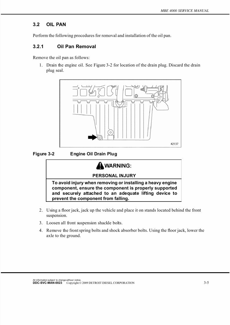
7/22/2019 Manual Mbe 4000 Taller
http://slidepdf.com/reader/full/manual-mbe-4000-taller 323/630
MBE 4000 SERVICE MANUAL
3.2 OIL PAN
Perform the following procedures for removal and installation of the oil pan.
3.2.1 Oil Pan Removal
Remove the oil pan as follows:
1. Drain the engine oil. See Figure 3-2 for location of the drain plug. Discard the drain
plug seal.
Figure 3-2 Engine Oil Drain Plug
PERSONAL INJURY
To avoid injury when removing or installing a heavy enginecomponent, ensure the component is properly supportedand securely attached to an adequate lifting device toprevent the component from falling.
2. Using a floor jack, jack up the vehicle and place it on stands located behind the front
suspension.
3. Loosen all front suspension shackle bolts.
4. Remove the front spring bolts and shock absorber bolts. Using the floor jack, lower the
axle to the ground.
All information subject to change without notice.
DDC-SVC-MAN-0023 Copyright © 2009 DETROIT DIESEL CORPORATION 3-5
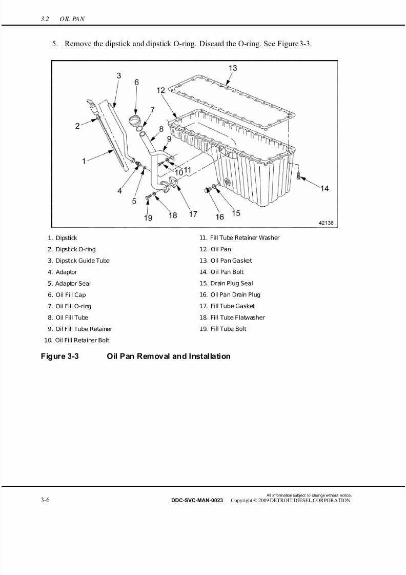
7/22/2019 Manual Mbe 4000 Taller
http://slidepdf.com/reader/full/manual-mbe-4000-taller 324/630
3.2 OIL PAN
5. Remove the dipstick and dipstick O-ring. Discard the O-ring. See Figure 3-3.
1. Dipstick 11. Fill Tube Retainer Washer
2. Dipstick O-ring 12. Oil Pan
3. Dipstick Guide Tube 13. Oil Pan Gasket
4. Adaptor 14. Oil Pan Bolt
5. Adaptor Seal 15. Drain Plug Seal
6. Oil Fill Cap 16. Oil Pan Drain Plug
7. Oil Fill O-ring 17. Fill Tube Gasket
8. Oil Fill Tube 18. Fill Tube Flatwasher
9. Oil Fill Tube Retainer 19. Fill Tube Bolt
10. Oil Fill Retainer Bolt
Figure 3-3 Oil Pan Removal and Installation
All information subject to change without notice.
3-6 DDC-SVC-MAN-0023 Copyright © 2009 DETROIT DIESEL CORPORATION
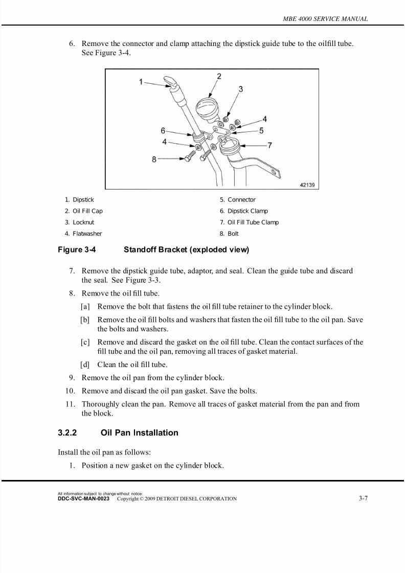
7/22/2019 Manual Mbe 4000 Taller
http://slidepdf.com/reader/full/manual-mbe-4000-taller 325/630
MBE 4000 SERVICE MANUAL
6. Remove the connector and clamp attaching the dipstick guide tube to the oil fill tube.
See Figure 3-4.
1. Dipstick 5. Connector
2. Oil Fill Cap 6. Dipstick Clamp
3. Locknut 7. Oil Fill Tube Clamp
4. Flatwasher 8. Bolt
Figure 3-4 Standoff Bracket (exploded view)
7. Remove the dipstick guide tube, adaptor, and seal. Clean the guide tube and discard
the seal. See Figure 3-3.
8. Remove the oil fill tube.
[a] Remove the bolt that fastens the oil fill tube retainer to the cylinder block.
[b] Remove the oil fill bolts and washers that fasten the oil fill tube to the oil pan. Save
the bolts and washers.
[c] Remove and discard the gasket on the oil fill tube. Clean the contact surfaces of the
fill tube and the oil pan, removing all traces of gasket material.
[d] Clean the oil fill tube.
9. Remove the oil pan from the cylinder block.
10. Remove and discar d the oil pan gasket. Save the bolts.
11. Thoroughly clean the pan. Remove all traces of gasket material from the pan and fromthe block.
3.2.2 Oil Pan Installation
Install the oil pan as follows:
1. Position a new gasket on the cylinder block.
All information subject to change without notice.
DDC-SVC-MAN-0023 Copyright © 2009 DETROIT DIESEL CORPORATION 3-7
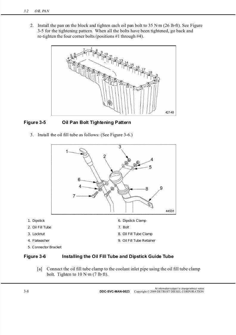
7/22/2019 Manual Mbe 4000 Taller
http://slidepdf.com/reader/full/manual-mbe-4000-taller 326/630
3.2 OIL PAN
2. Install the pan on the block and tighten each oil pan bolt to 35 N·m (26 lb·ft). See Figure
3-5 for the tightening pattern. When all the bolts have been tightened, go back and
re-tighten the four corner bolts (positions #1 through #4).
Figure 3-5 Oil Pan Bolt Tightening Pattern
3. Install the oil fill tube as follows: (See Figure 3-6.)
1. Dipstick 6. Dipstick Clamp
2. Oil Fill Tube 7. Bolt
3. Locknut 8. Oil Fill Tube Clamp
4. Flatwasher 9. Oil Fill Tube Retainer
5. Connector Bracket
Figure 3-6 Installing the Oil Fill Tube and Dipstick Guide Tube
[a] Connect the oil fill tube clamp to the coolant inlet pipe using the oil fill tube clamp
bolt. Tighten to 10 N·m (7 lb·ft).
All information subject to change without notice.
3-8 DDC-SVC-MAN-0023 Copyright © 2009 DETROIT DIESEL CORPORATION
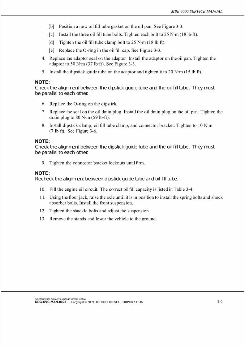
7/22/2019 Manual Mbe 4000 Taller
http://slidepdf.com/reader/full/manual-mbe-4000-taller 327/630
MBE 4000 SERVICE MANUAL
[b] Position a new oil fill tube gasket on the oil pan. See Figure 3-3.
[c] Install the three oil fill tube bolts. Tighten each bolt to 25 N·m (18 lb·ft).
[d] Tighten the oil fill tube clamp bolt to 25 N·m (18 lb·ft).
[e] Replace the O-ring in the oil fill cap. See Figure 3-3.
4. Replace the adaptor seal on the adaptor. Install the adaptor on the oil pan. Tighten theadaptor to 50 N·m (37 lb·ft). See Figure 3-3.
5. Install the dipstick guide tube on the adaptor and tighten it to 20 N·m (15 lb·ft).
NOTE:Check the alignment between the dipstick guide tube and the oil fill tube. They mustbe parallel to each other.
6. Replace the O-ring on the dipstick.
7. Replace the seal on the oil drain plug. Install the oil drain plug on the oil pan. Tighten the
drain plug to 80 N·m (59 lb·ft).
8. Install dipstick clamp, oil fill tube clamp, and connector bracket. Tighten to 10 N·m
(7 lb·ft). See Figure 3-6.
NOTE:Check the alignment between the dipstick guide tube and the oil fill tube. They mustbe parallel to each other.
9. Tighten the connector bracket locknuts until firm.
NOTE:Recheck the alignment between dipstick guide tube and oil fill tube.
10. Fill the engine oil circuit. The correct oil fill capacity is listed in Table 3-4.
11. Using the floor jack, raise the axle until it is in position to install the spring bolts and shock
absorber bolts. Install the front suspension.
12. Tighten the shackle bolts and adjust the suspension.
13. Remove the stands and lower the vehicle to the ground.
All information subject to change without notice.
DDC-SVC-MAN-0023 Copyright © 2009 DETROIT DIESEL CORPORATION 3-9
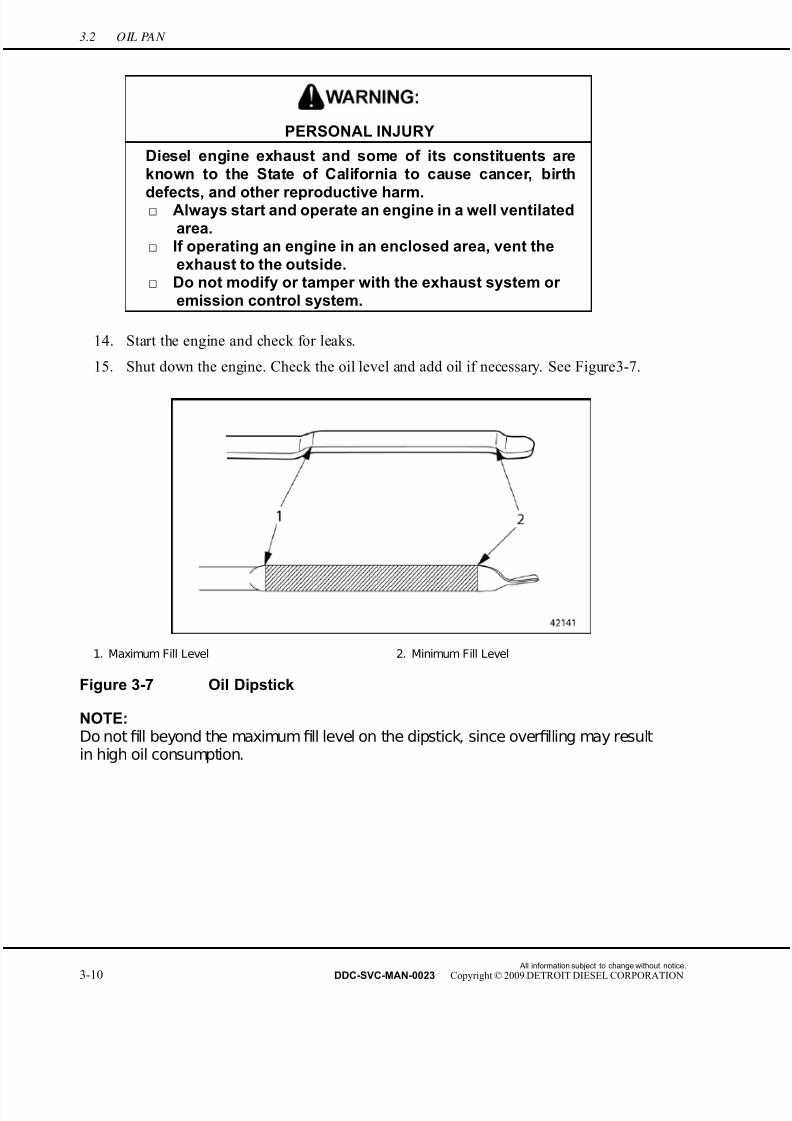
7/22/2019 Manual Mbe 4000 Taller
http://slidepdf.com/reader/full/manual-mbe-4000-taller 328/630
3.2 OIL PAN
PERSONAL INJURY
Diesel engine exhaust and some of its constituents areknown to the State of California to cause cancer, birth
defects, and other reproductive harm.□ Always start and operate an engine in a well ventilated
area.□ If operating an engine in an enclosed area, vent the
exhaust to the outside.□ Do not modify or tamper with the exhaust system or
emission control system.
14. Start the engine and check for leaks.
15. Shut down the engine. Check the oil level and add oil if necessary. See Figure 3-7.
1. Maximum Fill Level 2. Minimum Fill Level
Figure 3-7 Oil Dipstick
NOTE:Do not fill beyond the maximumfill level on the dipstick, since overfilling may resultin high oil consumption.
All information subject to change without notice.
3-10 DDC-SVC-MAN-0023 Copyright © 2009 DETROIT DIESEL CORPORATION

7/22/2019 Manual Mbe 4000 Taller
http://slidepdf.com/reader/full/manual-mbe-4000-taller 329/630
MBE 4000 SERVICE MANUAL
3.3 PISTON OIL SPRAY NOZZLE(S)
Perform the following procedures for removal and installation of the piston oil spr ay nozzle.
3.3.1 Piston Oil Spray Nozzle(s) Removal
Remove the piston oil spray nozzle(s) as follows:
NOTE: These procedures refer to bolt-on piston oil spray nozzles only.
1. Remove the oil pan. Refer to section 3.2.1.
2. Remove the inspection cover on the flywheel housing and install the engine cranking tool
(J–46392). See Figure 3-8. Rotate the crankshaft to gain access to the nozzle(s).
1. Inspection Cover
Figure 3-8 Installing the Engine Cranking Tool
All information subject to change without notice.
DDC-SVC-MAN-0023 Copyright © 2009 DETROIT DIESEL CORPORATION 3-11

7/22/2019 Manual Mbe 4000 Taller
http://slidepdf.com/reader/full/manual-mbe-4000-taller 330/630
3.3 PISTON OIL SPRAY NOZZLE(S)
3. Remove the hollow-core bolt that attaches each piston oil spray nozzle to the underside of
the cylinder block. Remove the oil spray nozzle from the engine. See Figure 3-9.
1. Piston Spray Nozzle 2. Hollow Core Bolt
Figure 3-9 Removing the Piston Oil Spray Nozzle(s)
NOTE:Piston cooling nozzle tool J –47301 is used to check the proper alignment of the piston oilspray nozzles for non-EGR and EGR engines built before March 2005. EGR engines
All information subject to change without notice.
3-12 DDC-SVC-MAN-0023 Copyright © 2009 DETROIT DIESEL CORPORATION
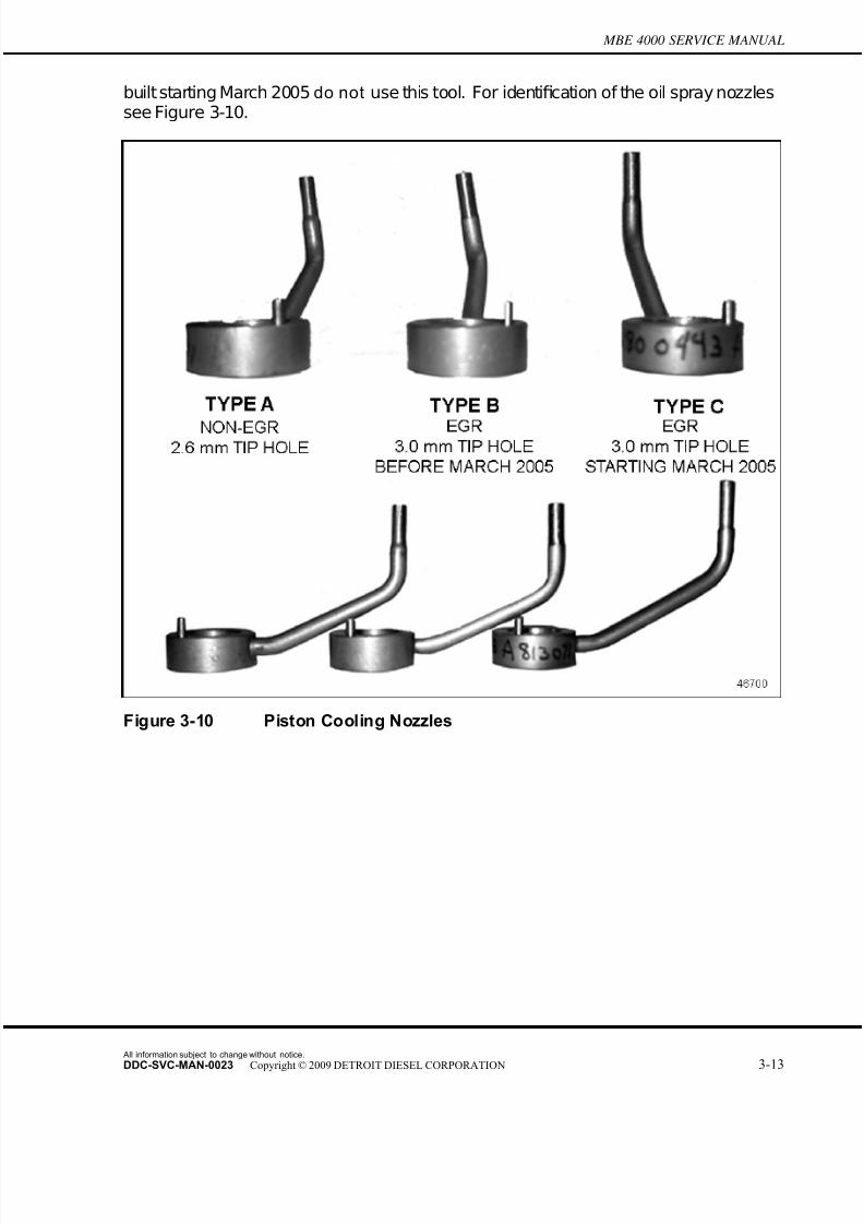
7/22/2019 Manual Mbe 4000 Taller
http://slidepdf.com/reader/full/manual-mbe-4000-taller 331/630
MBE 4000 SERVICE MANUAL
built starting March 2005 do not use this tool. For identification of the oil spray nozzlessee Figure 3-10.
Figure 3-10 Piston Cooling Nozzles
All information subject to change without notice.
DDC-SVC-MAN-0023 Copyright © 2009 DETROIT DIESEL CORPORATION 3-13
7/22/2019 Manual Mbe 4000 Taller
http://slidepdf.com/reader/full/manual-mbe-4000-taller 332/630
3.3 PISTON OIL SPRAY NOZZLE(S)
4. For non-EGR and EGR engine built before March 2005, check the piston oil spray
nozzle(s) using the piston cooling jet tool (J–47301). See Figure 3-11.
1. Knurled Bolt 3. Setting Rod
2. Piston Oil Spray Nozzle 4. Setting Device
Figure 3-11 Checking the Piston Oil Spray Nozzle(s)
[a] Secure the setting device (part of toolset J–47301) in a vise with protective jaws.
[b] Remove the knurled bolt and setting rod from the setting device. Install the piston
oil spray nozzle on the setting device. Hand tighten the knurled bolt enough to hold
the nozzle firmly.
[c] Insert the correct end of the setting rod through the base of the setting device and into
the tip of the piston oil spray nozzle. If the setting rod will not insert into the tip of the piston oil cooling nozzle, discard the nozzle and replace with a new nozzle.
NOTE: The setting rod is double ended, one end has a diameter of 2.6 mm (0.102 in.) fornon-EGR engines and the other end is 3.0 mm (0.118 in.) for EGR engines.
3.3.2 Piston Oil Spray Nozzle(s) Installation
Install the piston oil spray nozzle(s) as follows:
All information subject to change without notice.
3-14 DDC-SVC-MAN-0023 Copyright © 2009 DETROIT DIESEL CORPORATION
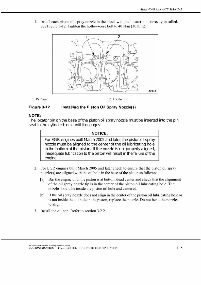
7/22/2019 Manual Mbe 4000 Taller
http://slidepdf.com/reader/full/manual-mbe-4000-taller 333/630
MBE 4000 SERVICE MANUAL
1. Install each piston oil spray nozzle in the block with the locator pin correctly installed.
See Figure 3-12. Tighten the hollow-core bolt to 40 N·m (30 lb·ft).
1. Pin Seat 2. Locator Pin
Figure 3-12 Installing the Piston Oil Spray Nozzle(s)
NOTE: The locator pin on the base of the piston oil spray nozzle must be inserted into the pinseat in the cylinder block until it engages.
NOTICE:
For EGR engines built March 2005 and later, the piston oil spraynozzle must be aligned to the center of the oil lubricating hole
in the bottom of the piston. If the nozzle is not properly aligned,inadequate lubrication to the piston will result in the failure of theengine.
2. For EGR engines built March 2005 and later check to ensure that the piston oil spray
nozzle(s) are aligned with the oil hole in the base of the piston as follows:
[a] Bar the engine until the piston is at bottom dead center and check that the alignment
of the oil spray nozzle tip is in the center of the piston oil lubricating hole. The
nozzle should be inside the piston oil hole and centered.
[b] If the oil spray nozzle does not align in the center of the piston oil lubricating hole or
is not inside the oil hole in the piston, replace the nozzle. Do not bend the nozzlesto align.
3. Install the oil pan. Refer to section 3.2.2.
All information subject to change without notice.
DDC-SVC-MAN-0023 Copyright © 2009 DETROIT DIESEL CORPORATION 3-15

7/22/2019 Manual Mbe 4000 Taller
http://slidepdf.com/reader/full/manual-mbe-4000-taller 334/630
3.3 PISTON OIL SPRAY NOZZLE(S)
4. Remove the engine cranking tool (J–46392) and install the the inspection cover. Torque
bolts on cover to 25 N·m (18 lb·ft)See Figure 3-13.
1. Inspection Cover
Figure 3-13 Installing the Engine Cranking Tool
5. Fill the crankcase to the specified oil level listed in Table 3-4. Do not over fill the crankcase.
All information subject to change without notice.
3-16 DDC-SVC-MAN-0023 Copyright © 2009 DETROIT DIESEL CORPORATION
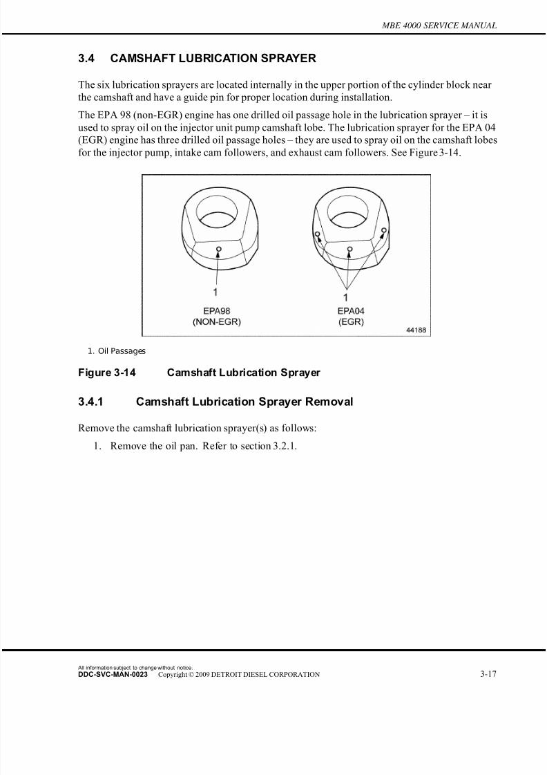
7/22/2019 Manual Mbe 4000 Taller
http://slidepdf.com/reader/full/manual-mbe-4000-taller 335/630
MBE 4000 SERVICE MANUAL
3.4 CAMSHAFT LUBRICATION SPRAYER
The six lubrication sprayers are located internally in the upper portion of the cyli nder block near
the camshaft and have a guide pin for proper location during installation.
The EPA 98 (non-EGR) engine has one drilled oil passage hole in the lubrication sprayer – it is
used to spray oil on the injector unit pump camshaft lobe. The lubrication sprayer for the EPA 04
(EGR) engine has three drilled oil passage holes – they are used to spray oil on the camshaft lobes
for the injector pump, intake cam followers, and exhaust cam followers. See Figure 3-14.
1. Oil Passages
Figure 3-14 Camshaft Lubrication Sprayer
3.4.1 Camshaft Lubrication Sprayer Removal
Remove the camshaft lubrication sprayer(s) as follows:
1. Remove the oil pan. Refer to section 3.2.1.
All information subject to change without notice.
DDC-SVC-MAN-0023 Copyright © 2009 DETROIT DIESEL CORPORATION 3-17
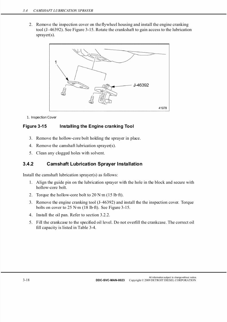
7/22/2019 Manual Mbe 4000 Taller
http://slidepdf.com/reader/full/manual-mbe-4000-taller 336/630
3.4 CAMSHAFT LUBRICATION SPRAYER
2. Remove the inspection cover on the flywheel housing and install the engine cranking
tool (J–46392). See Figure 3-15. Rotate the crankshaft to gain access to the lubrication
sprayer(s).
1. Inspection Cover
Figure 3-15 Installing the Engine cranking Tool
3. Remove the hollow-core bolt holding the sprayer in place.
4. Remove the camshaft lubrication sprayer(s).
5. Clean any clogged holes with solvent.
3.4.2 Camshaft Lubrication Sprayer Installation
Install the camshaft lubrication sprayer(s) as follows:
1. Align the guide pin on the lubrication sprayer with the hole in the block and secure with
hollow-core bolt.
2. Torque the hollow-core bolt to 20 N·m (15 lb·ft).
3. Remove the engine cranking tool (J–46392) and install the the inspection cover. Torque
bolts on cover to 25 N·m (18 lb·ft). See Figure 3-15.
4. Install the oil pan. Refer to section 3.2.2.
5. Fill the crankcase to the specified oil level. Do not over fill the crankcase. The correct oil
fill capacity is listed in Table 3-4.
All information subject to change without notice.
3-18 DDC-SVC-MAN-0023 Copyright © 2009 DETROIT DIESEL CORPORATION
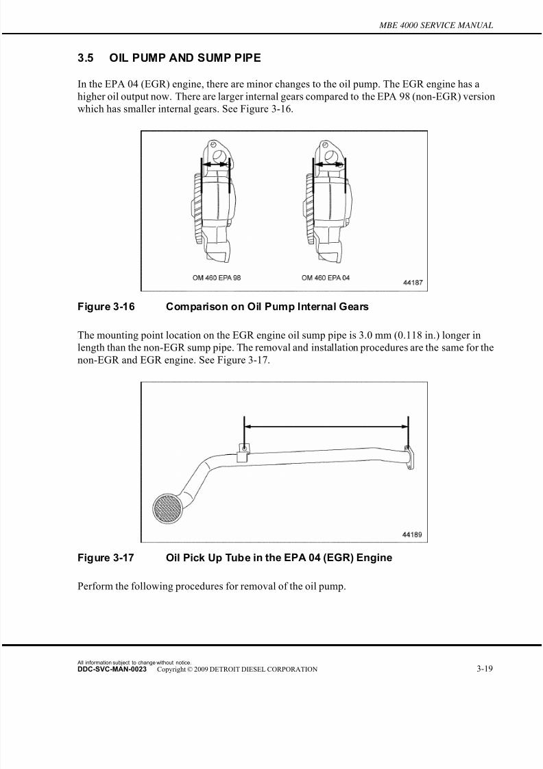
7/22/2019 Manual Mbe 4000 Taller
http://slidepdf.com/reader/full/manual-mbe-4000-taller 337/630
MBE 4000 SERVICE MANUAL
3.5 OIL PUMP AND SUMP PIPE
In the EPA 04 (EGR) engine, there are minor changes to the oil pump. The EGR engine has a
higher oil output now. There are larger internal gears compared to the EPA 98 (non-EGR) version
which has smaller internal gears. See Figure 3-16.
Figure 3-16 Comparison on Oil Pump Internal Gears
The mounting point location on the EGR engine oil sump pipe is 3.0 mm (0.118 in.) longer in
length than the non-EGR sump pipe. The removal and installation procedures are the same for the
non-EGR and EGR engine. See Figure 3-17.
Figure 3-17 Oil Pick Up Tube in the EPA 04 (EGR) Engine
Perform the following procedures for removal of the oil pump.
All information subject to change without notice.
DDC-SVC-MAN-0023 Copyright © 2009 DETROIT DIESEL CORPORATION 3-19

7/22/2019 Manual Mbe 4000 Taller
http://slidepdf.com/reader/full/manual-mbe-4000-taller 338/630
3.5 OIL PUMP AND SUMP PIPE
3.5.1 Oil Pump and Sump Pipe Removal
Remove the oil pump assembly as follows:
1. Remove the oil pan from the cylinder block. Refer to section 3.2.1.
2. Remove the sump pipe from the oil pump. See Figure 3-18.
[a] Remove the bolt attaching the sump pipe bracket to the cylinder block.
[b] Remove the two bolts attaching the sump pipe to the oil pump. Discard the gasket.
[c] Remove the sump pipe and bracket from the oil pump.
3. Remove the bolts attaching the pressure limiting valve to the oil pump and lower edge of
the cylinder block. Remove the pressure limiting valve from the oil pump. See Figure
3-18.
1. Valve Mounting Bolt 6. Sump P ipe Mounting Bolt
2. Pressure Limiting Valve 7. Sump P ipe
3. Oil Pump 8. Bracket
4. Oil P ump Mounting Bolt 9. Bracket Mounting B olt
5. Gasket
Figure 3-18 Oil Pump and Sump Pipe Removal
4. Remove the bolt attaching the oil pump to the cylinder block. Remove the oil pump from
the the cylinder block. See Figure 3-18.
5. Thoroughly clean the contact surfaces of the oil pump and cylinder block.
3.5.2 Oil Pump Disassembly
Disassemble the oil pump unit as follows:
1. Remove the oil pump from the cylinder block. Refer to section 3.5.1.
All information subject to change without notice.
3-20 DDC-SVC-MAN-0023 Copyright © 2009 DETROIT DIESEL CORPORATION
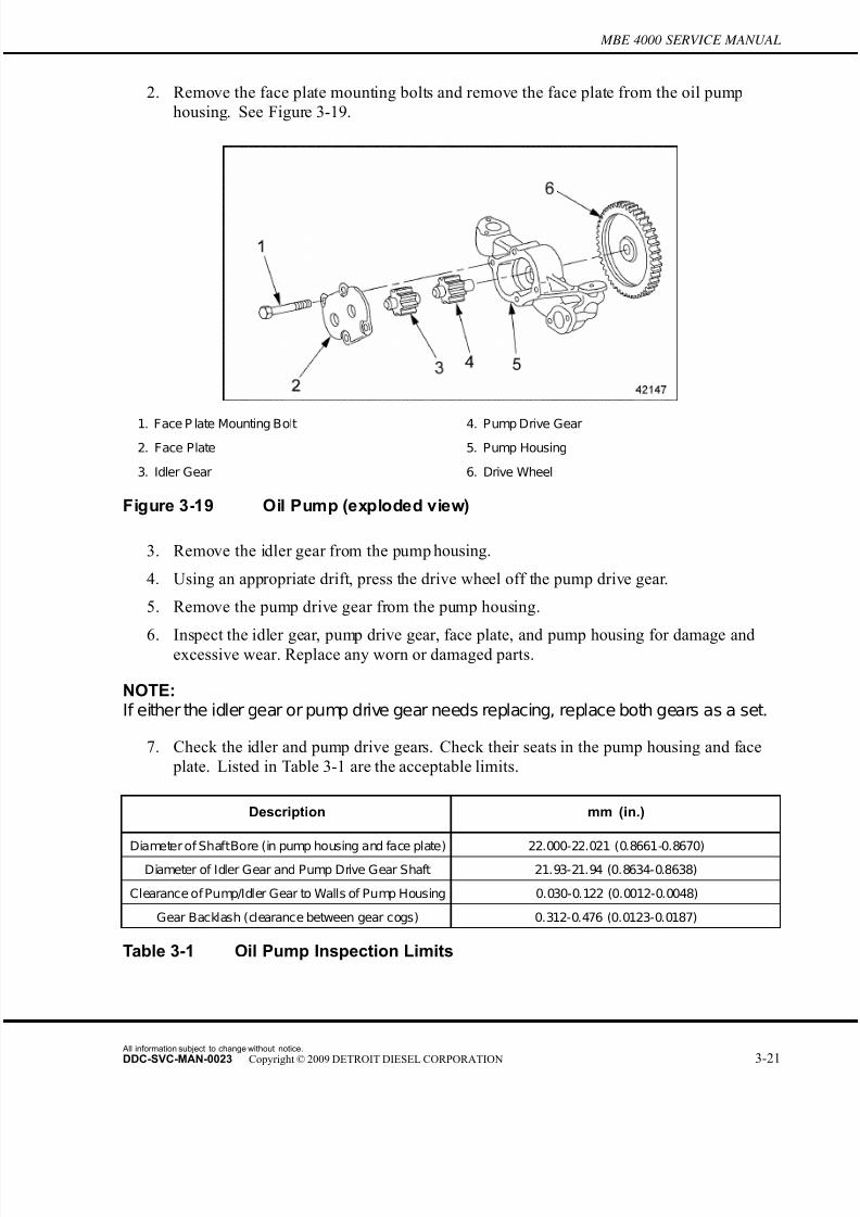
7/22/2019 Manual Mbe 4000 Taller
http://slidepdf.com/reader/full/manual-mbe-4000-taller 339/630
MBE 4000 SERVICE MANUAL
2. Remove the face plate mounting bolts and remove the face plate from the oil pump
housing. See Figure 3-19.
1. Face P late Mounting Bolt 4. Pump Drive Gear
2. Face Plate 5. Pump Housing
3. Idler Gear 6. Drive Wheel
Figure 3-19 Oil Pump (exploded view)
3. Remove the idler gear from the pump housing.
4. Using an appropriate drift, press the drive wheel off the pump drive gear.
5. Remove the pump drive gear from the pump housing.
6. Inspect the idler gear, pum p drive gear, face plate, and pump housing for damage andexcessive wear. Replace any worn or damaged parts.
NOTE:If either the idler gear or pump drive gear needs replacing, replace both gears as a set.
7. Check the idler and pump drive gears. Check their seats in the pump housing and face
plate. Listed in Table 3-1 are the acceptable limits.
Description mm (in.)
Diameter of ShaftBore (in pump housing and face plate) 22.000-22.021 (0.8661-0.8670)
Diameter of Idler Gear and Pump Drive Gear Shaft 21.93-21.94 (0.8634-0.8638)
Clearance of Pump/Idler Gear to Walls of Pump Housing 0.030-0.122 (0.0012-0.0048)
Gear Backlash (clearance between gear cogs) 0.312-0.476 (0.0123-0.0187)
Table 3-1 Oil Pump Inspection Limits
All information subject to change without notice.
DDC-SVC-MAN-0023 Copyright © 2009 DETROIT DIESEL CORPORATION 3-21
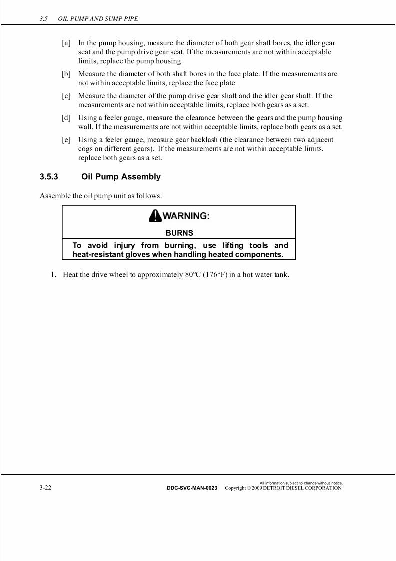
7/22/2019 Manual Mbe 4000 Taller
http://slidepdf.com/reader/full/manual-mbe-4000-taller 340/630
3.5 OIL PUMP AND SUMP PIPE
[a] In the pump housing, measure the diameter of both gear shaft bores, the idler gear
seat and the pump drive gear seat. If the measurements are not within acceptable
limits, replace the pump housing.
[b] Measure the diameter of both shaft bores in the face plate. If the measurements are
not within acceptable limits, replace the face plate.
[c] Measure the diameter of the pump drive gear shaft and the idler gear shaft. If themeasurements are not within acceptable limits, replace both gears as a set.
[d] Using a feeler gauge, measure the clearance between the gears and the pump housing
wall. If the measurements are not within acceptable limits, replace both gears as a set.
[e] Using a feeler gauge, measure gear backlash (the clearance between two adjacent
cogs on different gears). If the measurements are not within acceptable limits,
replace both gears as a set.
3.5.3 Oil Pump Assembly
Assemble the oil pump unit as follows:
BURNS
To avoid injury from burning, use lifting tools andheat-resistant gloves when handling heated components.
1. Heat the drive wheel to approximately 80°C (176°F) in a hot water tank.
All information subject to change without notice.
3-22 DDC-SVC-MAN-0023 Copyright © 2009 DETROIT DIESEL CORPORATION

7/22/2019 Manual Mbe 4000 Taller
http://slidepdf.com/reader/full/manual-mbe-4000-taller 341/630
MBE 4000 SERVICE MANUAL
2. Seat the pump drive gear in the pump housing. Using an appropriate drift, press in the
heated drive wheel until the pump drive gear projects slightly past the top of the dr ive
wheel. See Figure 3-20.
1. Pump Drive Gear 2. Drive Wheel
Figure 3-20 Positioning the Drive Wheel on the Pump Drive Gear
3. Using a feeler gauge, measure the projection of the pump drive gear. Adjust the position
of the pump drive gear until the projection equals 0.5 mm (0.02 in.), as listed in Table 3-2.
Description mm (in.)
Projection of Pump Drive Gear 0.5 (0.02)
P ump/Idler Gear E nd P lay 0.050-0.128 (0.0020-0.0050)
Table 3-2 Oil Pump Installation Specifications
4. Seat the idler gear in the pump housing.
5. Install the face plate on the pump housing. Tighten the mounting bolts to 25 N·m (18 lb·ft).
All information subject to change without notice.
DDC-SVC-MAN-0023 Copyright © 2009 DETROIT DIESEL CORPORATION 3-23

7/22/2019 Manual Mbe 4000 Taller
http://slidepdf.com/reader/full/manual-mbe-4000-taller 342/630
3.5 OIL PUMP AND SUMP PIPE
6. Using a dial gauge, measure the end play of the pump drive gear and idler gear against
the walls of the pump housing. See Figure 3-21 for set-up and listed in Table 3-2 are
the specifications.
1. Dial Gauge 3. Oil Pump
2. Support
Figure 3-21 Measuring the Clearance of the Pump Drive Gears
[a] Secure the assembled oil pump in a vise, with the face plate pointing up.
[b] Rest the dial gauge support on the face plate.
[c] Set up the dial gauge so that the feeler on the end of the gauge touches the exposed
end of the pump drive gear with some preload.
[d] Force the pump drive gear downward as far as it will go.
[e] At this position, adjust the scale of the dial gauge to "0" (zero).
[f] Now force the pump drive gear upward as far as it will go. Read the measurement on
the dial gauge and make sure it conforms to the range listed in Table 3-2. Replace
the pump, if necessary.
[g] Repeat this procedure for the idler gear.
7. Install the oil pump in the cylinder block. Refer to section 3.5.4.
3.5.4 Oil Pump and Sump Pipe Installation
Install the oil pump and Sump Pipe as follows:
1. Coat the contact surface between the block and the oil pump with Loctite® 574.
All information subject to change without notice.
3-24 DDC-SVC-MAN-0023 Copyright © 2009 DETROIT DIESEL CORPORATION
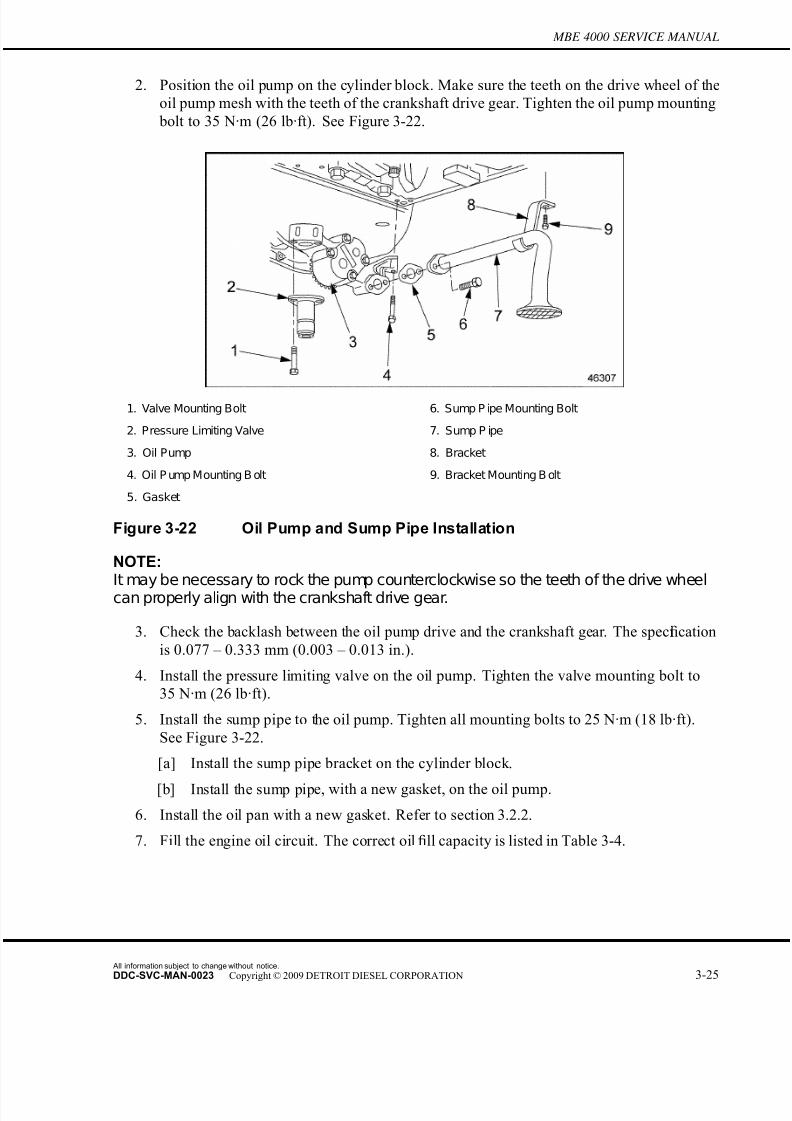
7/22/2019 Manual Mbe 4000 Taller
http://slidepdf.com/reader/full/manual-mbe-4000-taller 343/630
MBE 4000 SERVICE MANUAL
2. Position the oil pump on the cylinder block. Make sure the teeth on the drive wheel of the
oil pump mesh with the teeth of the crankshaft drive gear. Tighten the oil pump mounting
bolt to 35 N·m (26 lb·ft). See Figure 3-22.
1. Valve Mounting Bolt 6. Sump P ipe Mounting Bolt
2. Pressure Limiting Valve 7. Sump P ipe
3. Oil Pump 8. Bracket
4. Oil P ump Mounting B olt 9. Bracket Mounting B olt
5. Gasket
Figure 3-22 Oil Pump and Sump Pipe Installation
NOTE:It may be necessary to rock the pump counterclockwise so the teeth of the drive wheelcan properly align with the crankshaft drive gear.
3. Check the backlash between the oil pump drive and the crankshaft gear. The specification
is 0.077 – 0.333 mm (0.003 – 0.013 in.).
4. Install the pressure limiting valve on the oil pump. Tighten the valve mounting bolt to
35 N·m (26 lb·ft).
5. Install the sump pipe to the oil pump. Tighten all mounting bolts to 25 N·m (18 lb·ft).
See Figure 3-22.
[a] Install the sump pipe bracket on the cylinder block.
[b] Install the sump pipe, with a new gasket, on the oil pump.
6. Install the oil pan with a new gasket. Refer to section 3.2.2.
7. Fill the engine oil circuit. The correct oil fill capacity is listed in Table 3-4.
All information subject to change without notice.
DDC-SVC-MAN-0023 Copyright © 2009 DETROIT DIESEL CORPORATION 3-25

7/22/2019 Manual Mbe 4000 Taller
http://slidepdf.com/reader/full/manual-mbe-4000-taller 344/630
3.5 OIL PUMP AND SUMP PIPE
PERSONAL INJURY
Diesel engine exhaust and some of its constituents areknown to the State of California to cause cancer, birth
defects, and other reproductive harm.□ Always start and operate an engine in a well ventilated
area.□ If operating an engine in an enclosed area, vent the
exhaust to the outside.□ Do not modify or tamper with the exhaust system or
emission control system.
8. Start the engine and check for leaks.
9. Check the engine oil level and add oil if necessary.
All information subject to change without notice.
3-26 DDC-SVC-MAN-0023 Copyright © 2009 DETROIT DIESEL CORPORATION

7/22/2019 Manual Mbe 4000 Taller
http://slidepdf.com/reader/full/manual-mbe-4000-taller 345/630
MBE 4000 SERVICE MANUAL
3.6 OIL FILTER
Perform the following procedures for removal and installation of the oil filter.
3.6.1 Oil Filter Element Replacement
Replace the oil filter element as follows:
1. Clean the outside of the oil filter housing, then unscrew the oil filter cap from the housing.
See Figure 3-23.
Figure 3-23 Oil Filter Cap
NOTE:
Use care to prevent foreign objects from entering thefi
lter housing.
All information subject to change without notice.
DDC-SVC-MAN-0023 Copyright © 2009 DETROIT DIESEL CORPORATION 3-27
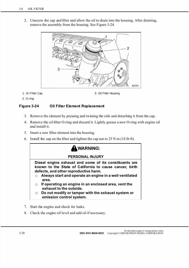
7/22/2019 Manual Mbe 4000 Taller
http://slidepdf.com/reader/full/manual-mbe-4000-taller 346/630
3.6 OIL FILTER
2. Unscrew the cap and filter and allow the oil to drain into the housing. After draining,
remove the assembly from the housing. See Figure 3-24.
1. Oil Filter Cap 3. Oil Filter Housing
2. O-ring
Figure 3-24 Oil Filter Element Replacement
3. Remove the element by pressing and twisting the side and detaching it from the cap.
4. Remove the oil filter O-ring and discard it. Lightly grease a new O-ring with engine oil
and install it.
5. Insert a new filter element into the housing.
6. Install the cap on the filter and tighten the cap nut to 25 N·m (18 lb·ft).
PERSONAL INJURY
Diesel engine exhaust and some of its constituents areknown to the State of California to cause cancer, birthdefects, and other reproductive harm.□ Always start and operate an engine in a well ventilated
area.□ If operating an engine in an enclosed area, vent the
exhaust to the outside.□ Do not modify or tamper with the exhaust system or
emission control system.
7. Start the engine and check for leaks.
8. Check the engine oil level and add oil if necessary.
All information subject to change without notice.
3-28 DDC-SVC-MAN-0023 Copyright © 2009 DETROIT DIESEL CORPORATION
7/22/2019 Manual Mbe 4000 Taller
http://slidepdf.com/reader/full/manual-mbe-4000-taller 347/630
MBE 4000 SERVICE MANUAL
3.7 OIL HEAT EXCHANGER/FILTER HOUSING
Perform the following procedures for removal and installation of the oil heat exchanger/filter
housing.
3.7.1 Oil Heat Exchanger/Filter Housing Removal
Remove the oil heat exchanger/filter housing as follows:
HOT COOLANT
To avoid scalding from the expulsion of hot coolant, never remove the cooling system pressure cap while the engineis at operating temperature. Wear adequate protectiveclothing (face shield, rubber gloves, apron, and boots).
Remove the cap slowly to relieve pressure.
1. When the engine is cool, drain the coolant from the radiator.
2. Remove the turbocharger from the engine.
3. Disconnect the coolant pump shunt line from the coolant pump inlet pipe and move it
out of the way.
4. Remove the oil filter cap. Inspect the O-ring and filter for damage and replace them if
necessary. Drain the oil remaining in the filter into a clean container.
5. Disconnect the wiring harness from the oil pressure/temperature sensor.
All information subject to change without notice.
DDC-SVC-MAN-0023 Copyright © 2009 DETROIT DIESEL CORPORATION 3-29

7/22/2019 Manual Mbe 4000 Taller
http://slidepdf.com/reader/full/manual-mbe-4000-taller 348/630
3.7 OIL HEAT EXCHANGER/FILTER HOUSING
6. Remove the oil heat exchanger/filter housing from the cylinder block. See Figure 3-25.
Catch any oil that drains out in a clean container. Discard the gasket and set aside t he
housing bolts for later installation.
1. Oil Filter C ap Nut 5. Oil Heat Exchanger/Filter Housing
2. Oil Filter Cap 6. Housing Bolt
3. Oil Filter Housing 7. Gasket
4. Oil Pressure/Temperature Sensor 8. Cylinder Block
Figure 3-25 Oil Heat Exchanger/Filter Housing Removal
NOTE: The oil filter housing and the heat exchanger housing are part of the same casting.
All information subject to change without notice.
3-30 DDC-SVC-MAN-0023 Copyright © 2009 DETROIT DIESEL CORPORATION
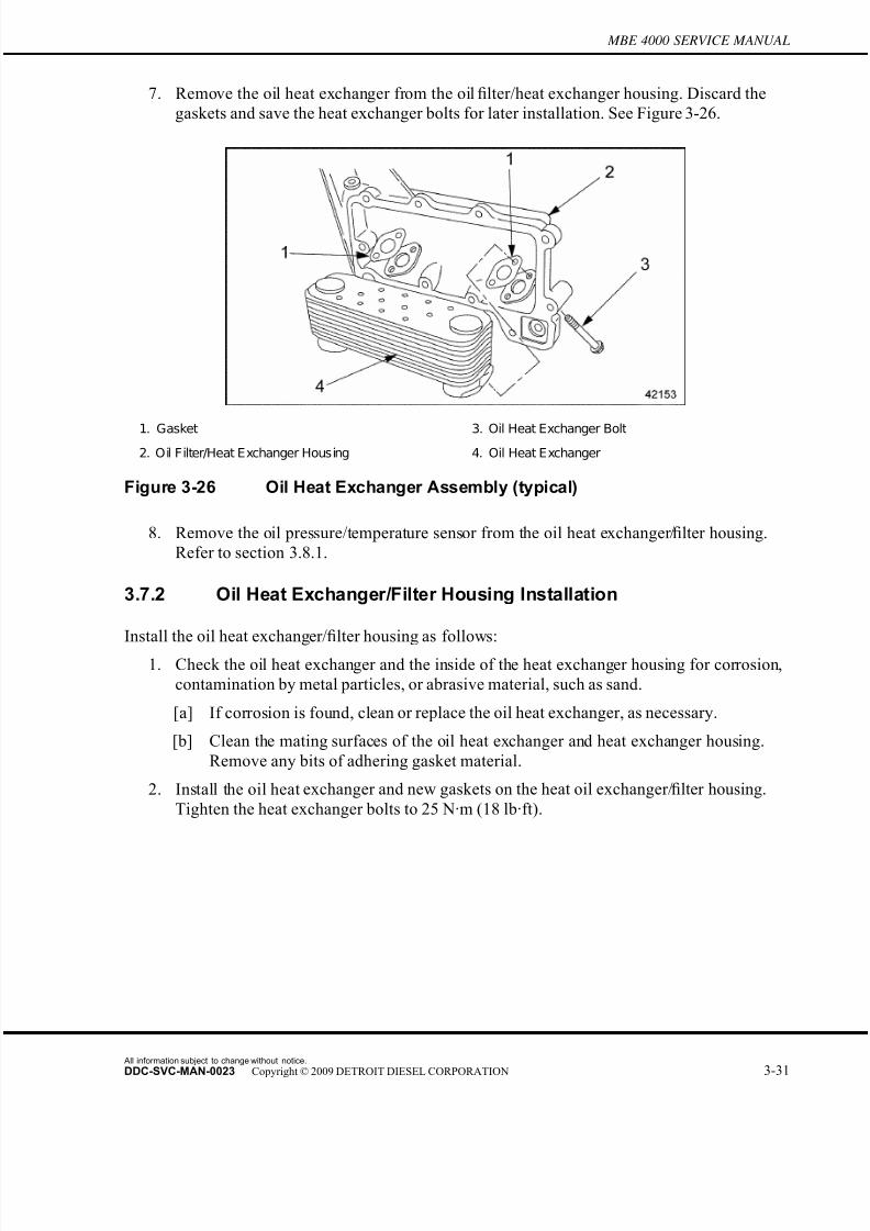
7/22/2019 Manual Mbe 4000 Taller
http://slidepdf.com/reader/full/manual-mbe-4000-taller 349/630
MBE 4000 SERVICE MANUAL
7. Remove the oil heat exchanger from the oil filter/heat exchanger housing. Discard the
gaskets and save the heat exchanger bolts for later installation. See Figure 3-26.
1. Gasket 3. Oil Heat Exchanger Bolt
2. Oil Filter/Heat Exchanger Housing 4. Oil Heat Exchanger
Figure 3-26 Oil Heat Exchanger Assembly (typical)
8. Remove the oil pressure/temperature sensor from the oil heat exchanger/filter housing.
Refer to section 3.8.1.
3.7.2 Oil Heat Exchanger/Filter Housing Installation
Install the oil heat exchanger/filter housing as follows:
1. Check the oil heat exchanger and the inside of the heat exchanger housing for corrosion,
contamination by metal particles, or abrasive material, such as sand.
[a] If corrosion is found, clean or replace the oil heat exchanger, as necessary.
[b] Clean the mating surfaces of the oil heat exchanger and heat exchanger housing.
Remove any bits of adhering gasket material.
2. Install the oil heat exchanger and new gaskets on the heat oil exchanger/filter housing.
Tighten the heat exchanger bolts to 25 N·m (18 lb·ft).
All information subject to change without notice.
DDC-SVC-MAN-0023 Copyright © 2009 DETROIT DIESEL CORPORATION 3-31
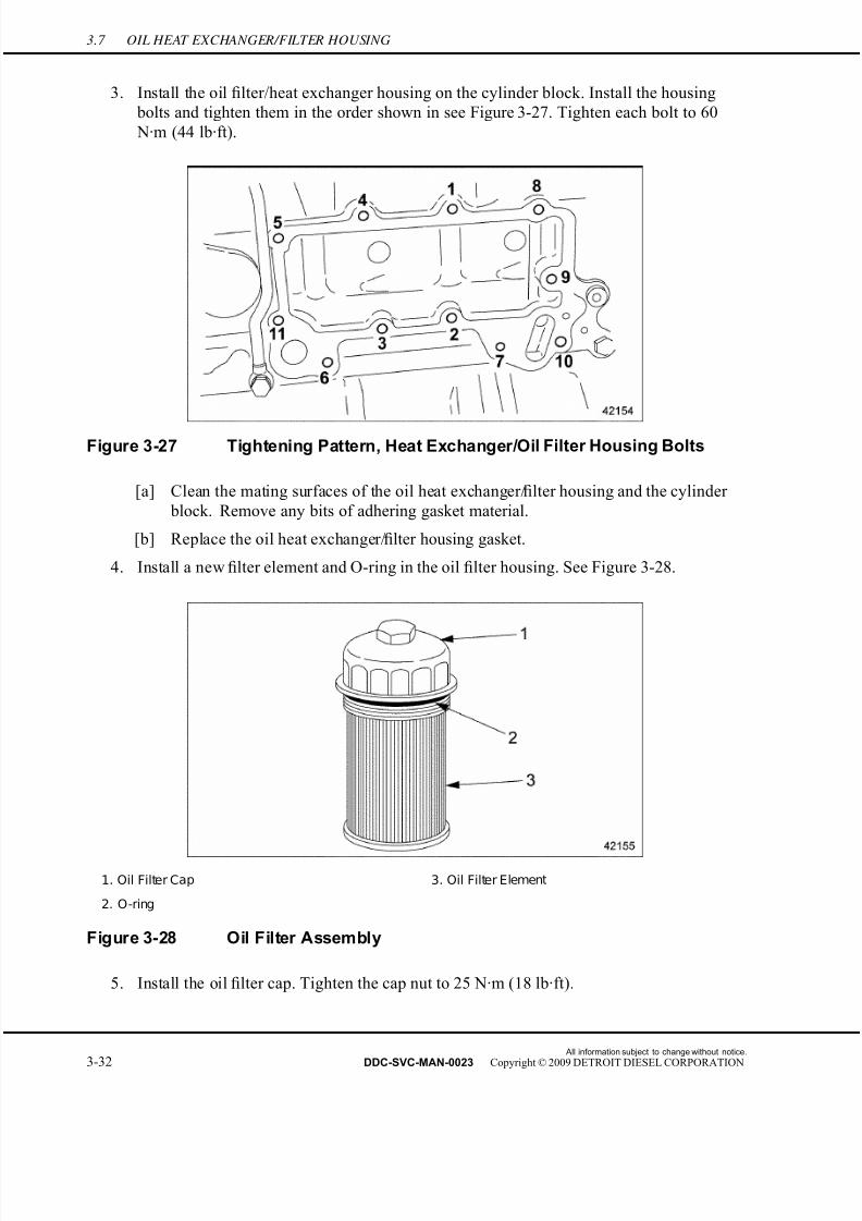
7/22/2019 Manual Mbe 4000 Taller
http://slidepdf.com/reader/full/manual-mbe-4000-taller 350/630
3.7 OIL HEAT EXCHANGER/FILTER HOUSING
3. Install the oil filter/heat exchanger housing on the cylinder block. Install the housing
bolts and tighten them in the order shown in see Figure 3-27. Tighten each bolt to 60
N·m (44 lb·ft).
Figure 3-27 Tightening Pattern, Heat Exchanger/Oil Filter Housing Bolts
[a] Clean the mating surfaces of the oil heat exchanger/filter housing and the cylinder
block. Remove any bits of adhering gasket material.
[b] Replace the oil heat exchanger/filter housing gasket.
4. Install a new filter element and O-ring in the oil filter housing. See Figure 3-28.
1. Oil Filter Cap 3. Oil Filter Element
2. O-ring
Figure 3-28 Oil Filter Assembly
5. Install the oil filter cap. Tighten the cap nut to 25 N·m (18 lb·ft).
All information subject to change without notice.
3-32 DDC-SVC-MAN-0023 Copyright © 2009 DETROIT DIESEL CORPORATION

7/22/2019 Manual Mbe 4000 Taller
http://slidepdf.com/reader/full/manual-mbe-4000-taller 351/630
MBE 4000 SERVICE MANUAL
6. Install the oil pressure/temperature sensor on the oil heat exchanger/filter housing.
Refer to section 3.8.2.
7. Connect the wiring harness to the oil pressure/temperature sensor.
8. Install the turbocharger on the engine. Refer to section 6.3.3.
9. Connect the coolant pump shunt line to the coolant pump inlet pipe.
10. Fill the cooling system. Refer to section 4.1.1.
PERSONAL INJURY
Diesel engine exhaust and some of its constituents areknown to the State of California to cause cancer, birthdefects, and other reproductive harm.□ Always start and operate an engine in a well ventilated
area.□ If operating an engine in an enclosed area, vent the
exhaust to the outside.□ Do not modify or tamper with the exhaust system or
emission control system.
11. Start the engine. Check the gauge for the correct oil pressure; check the oil lubrication
system and the coolant pump inlet pipe for leaks. The correct oil pressures are
listed in Table 3-3.
Engine Speed Minimum Pressure – kPa (psi)
At idling rpm 50 (7.0)
At maximum rpm 250 (36.0)
Table 3-3 Engine Oil Pressures
All information subject to change without notice.
DDC-SVC-MAN-0023 Copyright © 2009 DETROIT DIESEL CORPORATION 3-33

7/22/2019 Manual Mbe 4000 Taller
http://slidepdf.com/reader/full/manual-mbe-4000-taller 352/630

7/22/2019 Manual Mbe 4000 Taller
http://slidepdf.com/reader/full/manual-mbe-4000-taller 353/630
MBE 4000 SERVICE MANUAL
PERSONAL INJURY
Diesel engine exhaust and some of its constituents areknown to the State of California to cause cancer, birth
defects, and other reproductive harm.□ Always start and operate an engine in a well ventilated
area.□ If operating an engine in an enclosed area, vent the
exhaust to the outside.□ Do not modify or tamper with the exhaust system or
emission control system.
4. Start the engine. Check the gauge for the correct oil pressure listed in Table 3-9; and check
the lubrication system for leaks.
5. Check and add engine oil as needed.
All information subject to change without notice.
DDC-SVC-MAN-0023 Copyright © 2009 DETROIT DIESEL CORPORATION 3-35
7/22/2019 Manual Mbe 4000 Taller
http://slidepdf.com/reader/full/manual-mbe-4000-taller 354/630

7/22/2019 Manual Mbe 4000 Taller
http://slidepdf.com/reader/full/manual-mbe-4000-taller 355/630
MBE 4000 SERVICE MANUAL
3.A ADDITIONAL INFORMATION
Description Page
SP ECIFICATIONS ............................................................................................. 3-37Lubrication System ......................................................................................... 3-37
Oil Pump ......................................................................................................... 3-39
Oil Heat Exchanger ........................................................................................ 3-39
SPECIFICATIONS
This section contains the specifications for servicing the engine.
Lubrication System
Listed in Table 3-4 is the lubricating oil capacity for the engine. The lubrication system torque
values are listed in Table 3-5 and listed in Table 3-6.
Description All Engines – L (qts)
Oil Pan Capacity 40 (42)
Engine Oil Fill Capacity * 43.5 (46.0)
*In standard oil pan, including oil filter.
Table 3-4 Lubricating Oil Capacity
All information subject to change without notice.
DDC-SVC-MAN-0023 Copyright © 2009 DETROIT DIESEL CORPORATION 3-37

7/22/2019 Manual Mbe 4000 Taller
http://slidepdf.com/reader/full/manual-mbe-4000-taller 356/630
Description N·m (lb·ft)
Adaptor Nut (to oil pan) 50 (37)
Dipstick Guide Tube Fitting (to adaptor) 20 (15)
Oil Heat E xchanger/Filter Housing B olts (to block) 60 (44)
Oil Heat Exchanger Bolts (heat exchanger to housing) 25-30 (18-22)
Oil Fill Tube Bolt (to oil pan) 25 (18)
Oil Fill Tube Retainer Bolt (to block) 25 (18)
Oil Filter Cap 25 (18)
Oil Pan Drain Plug 80 (59)
Oil Pan Bolts (to block) 35 (26)
Oil P ressure/Temperature S ensor Mounting S crews 8-10 (6-7)
Oil Pump Face Plate Mounting Bolts (to oil pump
housing)
25 (18)
Oil Pump Mounting Bolt (to block) 35 (26)
Oil Spray Nozzle Hollow-Core Bolt 40 (30)
Pressure Limiting Valve Bolts (to block) 35 (26)
Sump Pipe Bracket to Crankcase Bolt 25 (18)
Sump Pipe Mounting Bolt (to oil pump) 25 (18)
Table 3-5 Torque Values
Description Torque, N·m (lb·ft)
Injector Unit Pump (IUP) Lubricator Bolt 20 (15)
Main Oil Gallery - Engine Block Rear bottom
plug - M26 x 1.5
150 (110)
Main Oil Gallery - Inner Plug - M22 x 1.5 50 (37)
Main Oil G allery - Engine Block R ear Top P lug - M24 x 1.5 120 (89)
Main O il Gallery - E ngine Block F ront P lug - M22 X 1.5 100 (74)
Main Oil Gallery - E ngine RIght Hand Side Top Plug
before the Oil Filter Housing - M18 x 1.5
60 (44)
Main Oil Gallery - Engine Right Hand Side Bottom Plug
before the Oil Filter Housing - M16 x 1.5
60 (44)
Main Oil Gallery - Engine Right Hand S ide Bottom
Plug after the Oil Filter Housing - M16 x 1.5
60 (44)
Table 3-6 Torque Values
All information subject to change without notice.
3-38 DDC-SVC-MAN-0023 Copyright © 2009 DETROIT DIESEL CORPORATION
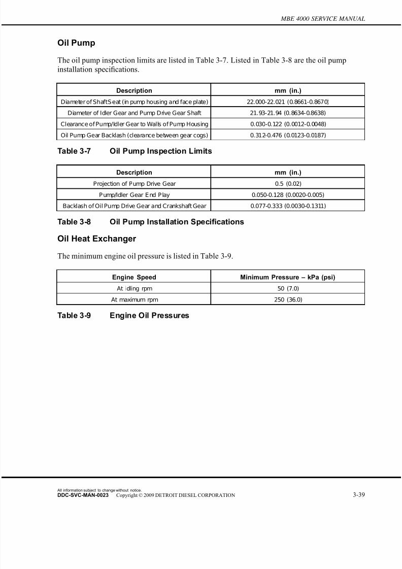
7/22/2019 Manual Mbe 4000 Taller
http://slidepdf.com/reader/full/manual-mbe-4000-taller 357/630
MBE 4000 SERVICE MANUAL
Oil Pump
The oil pump inspection limits are listed in Table 3-7. Listed in Table 3-8 are the oil pump
installation specifications.
Description mm (in.)
Diameter of ShaftS eat (in pump housing and face plate) 22.000-22.021 (0.8661-0.8670)
Diameter of Idler Gear and Pump Drive Gear Shaft 21.93-21.94 (0.8634-0.8638)
Clearance of Pump/Idler Gear to Walls of Pump Housing 0.030-0.122 (0.0012-0.0048)
Oil Pump Gear Backlash (clearance between gear cogs) 0.312-0.476 (0.0123-0.0187)
Table 3-7 Oil Pump Inspection Limits
Description mm (in.)
Projection of Pump Drive Gear 0.5 (0.02)
P ump/Idler Gear E nd P lay 0.050-0.128 (0.0020-0.005)
Backlash of Oil Pump Drive Gear and Crankshaft Gear 0.077-0.333 (0.0030-0.1311)
Table 3-8 Oil Pump Installation Specifications
Oil Heat Exchanger
The minimum engine oil pressure is listed in Table 3-9.
Engine Speed Minimum Pressure – kPa (psi)
At idling rpm 50 (7.0)
At maximum rpm 250 (36.0)
Table 3-9 Engine Oil Pressures
All information subject to change without notice.
DDC-SVC-MAN-0023 Copyright © 2009 DETROIT DIESEL CORPORATION 3-39

7/22/2019 Manual Mbe 4000 Taller
http://slidepdf.com/reader/full/manual-mbe-4000-taller 358/630
All information subject to change without notice.
3-40 DDC-SVC-MAN-0023 Copyright © 2009 DETROIT DIESEL CORPORATION
7/22/2019 Manual Mbe 4000 Taller
http://slidepdf.com/reader/full/manual-mbe-4000-taller 359/630
4 COOLING SYSTEM
Section Page
4.1 COOLING SY STEM ................................................................................. 4-3
4.2 COOLANT PUMP .................................................................................... 4-7
4.3 EGR COOLANT PUMP ............................................................................ 4-18
4.4 FRONT IDLER AND TENSIONER SUPPORT ........................................ 4-19
4.5 THERMOSTAT ......................................................................................... 4-22
4.6 EGR THERMOSTAT HOUSING .............................................................. 4-27
4.7 COOLANT TEMPERATURE SENSOR .................................................... 4-29
4.A ADDITIONAL INFORMATION .................................................................. 4-31

7/22/2019 Manual Mbe 4000 Taller
http://slidepdf.com/reader/full/manual-mbe-4000-taller 360/630
All information subject to change without notice.
4-2 DDC-SVC-MAN-0023 Copyright © 2009 DETROIT DIESEL CORPORATION
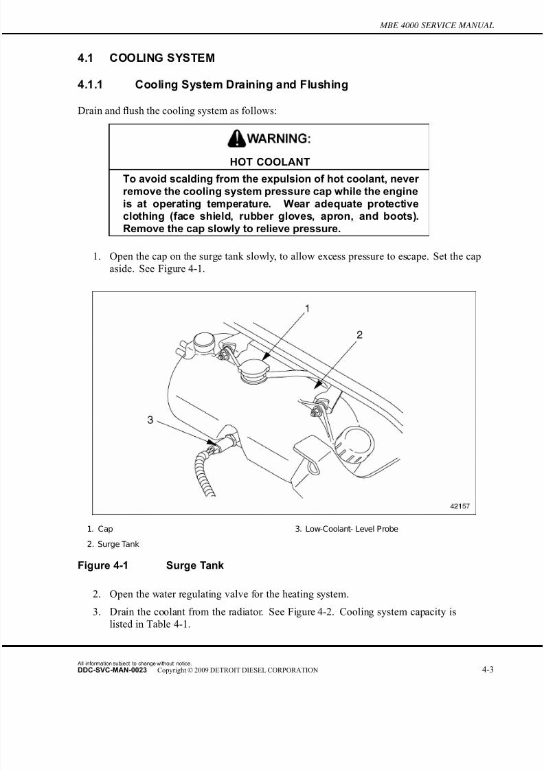
7/22/2019 Manual Mbe 4000 Taller
http://slidepdf.com/reader/full/manual-mbe-4000-taller 361/630
MBE 4000 SERVICE MANUAL
4.1 COOLING SYSTEM
4.1.1 Cooling System Draining and Flushing
Drain and flush the cooling system as follows:
HOT COOLANT
To avoid scalding from the expulsion of hot coolant, never remove the cooling system pressure cap while the engineis at operating temperature. Wear adequate protectiveclothing (face shield, rubber gloves, apron, and boots).Remove the cap slowly to relieve pressure.
1. Open the cap on the surge tank slowly, to allow excess pressure to escape. Set the cap
aside. See Figure 4-1.
1. Cap 3. Low-Coolant- Level Probe
2. Surge Tank
Figure 4-1 Surge Tank
2. Open the water regulating valve for the heating system.
3. Drain the coolant from the radiator. See Figure 4-2. Cooling system capacity is
listed in Table 4-1.
All information subject to change without notice.
DDC-SVC-MAN-0023 Copyright © 2009 DETROIT DIESEL CORPORATION 4-3

7/22/2019 Manual Mbe 4000 Taller
http://slidepdf.com/reader/full/manual-mbe-4000-taller 362/630
4.1 COOLING SYSTEM
Figure 4-2 Coolant Drain Plug
Description Capacity in liters (Quarts)
Engine Coolant Capacity (all vehicles
Engine capacity* 30.0 (31.7)
Century Class and Columbia C ooling System Capacity
Total capacity† 57.4 (60.7)
Antifreeze quantity at 50 percent 28.7 (30.4)
Antifreeze quantity at 55 percent 31.6 (33.4)
Sterling A-Line and L-Line Cooling System Capacity
Total capacity 53.8 (56.8)
Antifreeze quantity at 50 percent 26.9 (28.4)
Antifreeze quantity at 55 percent 29.6 (31.3)
FL112 Cooling System Capacity
Total capacity 42.0 (44.4)
Antifreeze quantity at 50 percent 21.0 (22.2)
Antifreeze quantity at 55 percent 23.1 (24.4)
* Does not include capacity of cooling system.
†With 1200 sq. ft. radiator.
Table 4-1 Cooling System Capacity
All information subject to change without notice.
4-4 DDC-SVC-MAN-0023 Copyright © 2009 DETROIT DIESEL CORPORATION
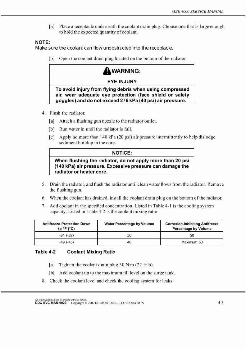
7/22/2019 Manual Mbe 4000 Taller
http://slidepdf.com/reader/full/manual-mbe-4000-taller 363/630
MBE 4000 SERVICE MANUAL
[a] Place a receptacle underneath the coolant drain plug. Choose one that is large enough
to hold the expected quantity of coolant.
NOTE:Make sure the coolant can flow unobstructed into the receptacle.
[b] Open the coolant drain plug located on the bottom of the radiator.
EYE INJURY
To avoid injury from flying debris when using compressedair, wear adequate eye protection (face shield or safetygoggles) and do not exceed 276 kPa (40 psi) air pressure.
4. Flush the radiator.
[a] Attach a flushing gun nozzle to the radiator outlet.[b] Run water in until the radiator is full.
[c] Apply no more than 140 kPa (20 psi) air pressure intermittently to help dislodge
sediment buildup in the core.
NOTICE:
When flushing the radiator, do not apply more than 20 psi(140 kPa) air pressure. Excessive pressure can damage theradiator or heater core.
5. Drain the radiator, and flush the radiator until clean water flows from the radiator. Removethe flushing gun.
6. When the coolant has drained, install the coolant drain plug on the bottom of the radiator.
7. Add coolant in the specified concentration. Listed in Table 4-1 is the cooling system
capacity. Listed in Table 4-2 is the coolant mixing ratio.
Antifreeze Protection Down
to °F (°C)
Water Percentage by Volume Corrosion-Inhibiting Antifreeze
Percentage by Volume
-34 (-37) 50 50
-49 (-45) 40 Maximum 60
Table 4-2 Coolant Mixing Ratio
[a] Tighten the coolant drain plug 30 N·m (22 ft·lb).
[b] Add coolant up to the maximum fill level on the surge tank.
8. Check the coolant level and check the cooling system for leaks.
All information subject to change without notice.
DDC-SVC-MAN-0023 Copyright © 2009 DETROIT DIESEL CORPORATION 4-5
7/22/2019 Manual Mbe 4000 Taller
http://slidepdf.com/reader/full/manual-mbe-4000-taller 364/630
4.1 COOLING SYSTEM
PERSONAL INJURY
Diesel engine exhaust and some of its constituents areknown to the State of California to cause cancer, birth
defects, and other reproductive harm.□ Always start and operate an engine in a well ventilated
area.□ If operating an engine in an enclosed area, vent the
exhaust to the outside.□ Do not modify or tamper with the exhaust system or
emission control system.
[a] Start the engine and run it for about one minute at varying speeds to release air
pockets in the cooling system.
[b] Check all hoses at the radiator, coolant pump, and surge tank for leaks.
[c] Check the coolant level and add more coolant if necessary.
9. Shut down the engine.
10. Close and tighten the cap on the surge tank.
All information subject to change without notice.
4-6 DDC-SVC-MAN-0023 Copyright © 2009 DETROIT DIESEL CORPORATION

7/22/2019 Manual Mbe 4000 Taller
http://slidepdf.com/reader/full/manual-mbe-4000-taller 365/630
MBE 4000 SERVICE MANUAL
4.2 COOLANT PUMP
Perform the following procedures for removal and installation of the coolant pump.
4.2.1 Coolant Pump Removal
Remove the coolant pump as follows:
HOT COOLANT
To avoid scalding from the expulsion of hot coolant, never remove the cooling system pressure cap while the engineis at operating temperature. Wear adequate protectiveclothing (face shield, rubber gloves, apron, and boots).Remove the cap slowly to relieve pressure.
1. Drain the coolant from the engine. Refer to section 4.1.1.
2. Remove the fan.
3. Release the tension on the main drive belt and the fan belt and set the belts aside
All information subject to change without notice.
DDC-SVC-MAN-0023 Copyright © 2009 DETROIT DIESEL CORPORATION 4-7
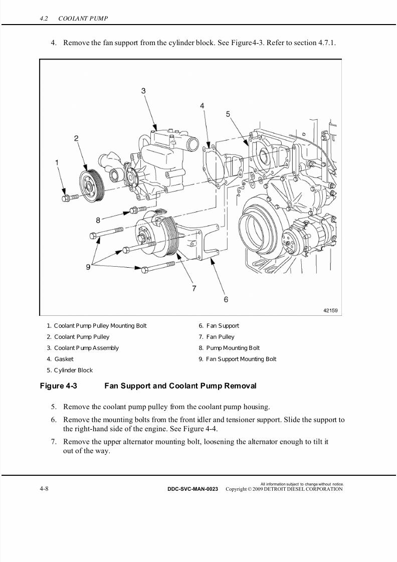
7/22/2019 Manual Mbe 4000 Taller
http://slidepdf.com/reader/full/manual-mbe-4000-taller 366/630
4.2 COOLANT PUMP
4. Remove the fan support from the cylinder block. See Figure 4-3. Refer to section 4.7.1.
1. Coolant Pump Pulley Mounting Bolt 6. Fan Support
2. Coolant Pump Pulley 7. Fan Pulley
3. Coolant P ump Assembly 8. Pump Mounting Bolt
4. Gasket 9. Fan Support Mounting Bolt
5. C ylinder Block
Figure 4-3 Fan Support and Coolant Pump Removal
5. Remove the coolant pump pulley from the coolant pump housing.
6. Remove the mounting bolts from the front idler and tensioner support. Slide the support to
the right-hand side of the engine. See Figure 4-4.
7. Remove the upper alternator mounting bolt, loosening the alternator enough to tilt it
out of the way.
All information subject to change without notice.
4-8 DDC-SVC-MAN-0023 Copyright © 2009 DETROIT DIESEL CORPORATION

7/22/2019 Manual Mbe 4000 Taller
http://slidepdf.com/reader/full/manual-mbe-4000-taller 367/630
MBE 4000 SERVICE MANUAL
8. Remove the inlet pipe from the coolant pump housing. See Figure 4-4.
1. Lower Coolant Tube 5. Coolant Pump Housing
2. Inlet P ipe Mounting Bolt 6. F ront I dler and Tensioner Support
3. Inlet Pipe 7. Coolant Pump Support Mounting Bolt
4. Inlet Pipe Gasket 8. Upper Coolant Tube
Figure 4-4 Coolant Pump Inlet Pipe (exploded view)
NOTE:Catch any coolant that runs out of the inlet pipe or coolant pump in a suitable container.
9. Remove the upper coolant tube from the thermostat housing.
10. Remove the coolant pump from the cylinder block. Discard the gasket.
11. On both the coolant pump and the cylinder block, clean the sealing surfaces (where the
gasket was attached) of any adhering bits of gasket material.
All information subject to change without notice.
DDC-SVC-MAN-0023 Copyright © 2009 DETROIT DIESEL CORPORATION 4-9
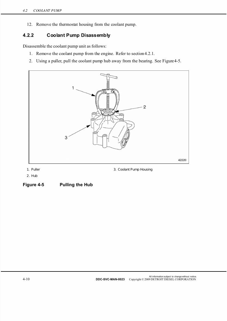
7/22/2019 Manual Mbe 4000 Taller
http://slidepdf.com/reader/full/manual-mbe-4000-taller 368/630
4.2 COOLANT PUMP
12. Remove the thermostat housing from the coolant pump.
4.2.2 Coolant Pump Disassembly
Disassemble the coolant pump unit as follows:
1. Remove the coolant pump from the engine. Refer to section 4.2.1.
2. Using a puller, pull the coolant pump hub away from the bearing. See Figure 4-5.
1. Puller 3. Coolant Pump Housing
2. Hub
Figure 4-5 Pulling the Hub
All information subject to change without notice.
4-10 DDC-SVC-MAN-0023 Copyright © 2009 DETROIT DIESEL CORPORATION
7/22/2019 Manual Mbe 4000 Taller
http://slidepdf.com/reader/full/manual-mbe-4000-taller 369/630
MBE 4000 SERVICE MANUAL
3. Remove the snap ring from the coolant pump housing. See Figure 4-6.
1. Hub 4. Coolant Pump Housing
2. Snap Ring 5. Sleeve Seal
3. Drive S haft and Bearing Assembly 6. Impeller
Figure 4-6 Coolant Pump Assembly (exploded view)
All information subject to change without notice.
DDC-SVC-MAN-0023 Copyright © 2009 DETROIT DIESEL CORPORATION 4-11

7/22/2019 Manual Mbe 4000 Taller
http://slidepdf.com/reader/full/manual-mbe-4000-taller 370/630
4.2 COOLANT PUMP
4. Using an appropriate drift, press the drive shaft and bearing assembly out of the impeller
and through the coolant pump housing. This frees the impeller from the housing.
See Figure 4-7.
1. Sleeve Seal 4. Receptacle
2. Drift 5. Drive Shaft and Bearing Assembly
3. Impeller
Figure 4-7 Removing the Drive Shaft
5. Remove the sleeve seal from the coolant pump housing.
4.2.2.1 Coolant Pump Inspection
Inspect the coolant pump unit as follows:
1. Check all coolant pump components for signs of damage. Replace any damaged
components.
All information subject to change without notice.
4-12 DDC-SVC-MAN-0023 Copyright © 2009 DETROIT DIESEL CORPORATION
7/22/2019 Manual Mbe 4000 Taller
http://slidepdf.com/reader/full/manual-mbe-4000-taller 371/630
MBE 4000 SERVICE MANUAL
2. Measure the following wear dimensions. Replace any component that is not within
tolerance as Listed in Table 4-3.
Description Wear Dimensions, mm (in.)
Drive Shaft Diameter (at the hub) 25.048-25.061 (0.9861-0.9867)
Hub Inside Diameter 24.995-25.008 (0.9841-0.9846)
Bearing Outside Diameter 54.981-54.994 (2.1646-2.1651)
Bearing Housing Diameter 54.930-54.960 (2.1626-2.1638)
Drive Shaft Diameter (at the impeller) 15.045-15.056 (0.5923-0.5928)
Impeller Inside Diameter 15.000-15.018 (0.5906-0.5913)
Impeller Outside Diameter 124-125 (4.88-4.92)
Impeller - Maximum Out-Of-Round 0.15 (0.0059)
Table 4-3 Coolant Pump Assembly Wear Dimensions
4.2.3 Coolant Pump Assembly
Assemble the coolant pump unit as follows:
1. Press the drive shaft and bearing assembly into the coolant pump housing. See Figure 4-8.
1. Drive Shaft
2. Coolant Pump Housing
Figure 4-8 Installing the Drive Shaft
[a] Place the coolant pump housing in a press.
[b] Place the coolant pump pressure piece, (J 45388 ), over the outer bearing race.
[c] Place the receptacle, (J 45388 ), under the coolant pump housing.
All information subject to change without notice.
DDC-SVC-MAN-0023 Copyright © 2009 DETROIT DIESEL CORPORATION 4-13

7/22/2019 Manual Mbe 4000 Taller
http://slidepdf.com/reader/full/manual-mbe-4000-taller 372/630
4.2 COOLANT PUMP
NOTICE:
To prevent damage to the drive shaft and bearing assembly,press only on the outer bearing race.
[d] Press the outer race of the bearing into the coolant pump housing.
2. Secure the bearing in place with the snap ring.
PERSONAL INJURY
To avoid injury from hot surfaces, wear protective gloves,or allow engine to cool before removing any component.
3. Press the hub onto the drive shaft and bearing assembly.
[a] Heat the hub to 175°F (80°C).
NOTICE:
To prevent damage to the bearing, make sure the drive shaftis supported evenly before pressing on the hub.
[b] Press the hub onto the drive shaft, while holding the bearing and drive shaft assembly
to prevent it from turning. Make sure the hub is flush with the end of the drive shaft.
4. Using the coolant pump bearing drift (352 589 08 15 00), press the sleeve seal into the
coolant pump housing. See Figure 4-9.
1. S leeve Seal 3. Coolant Pump Housing
2. Drive Shaft
Figure 4-9 Installing the Sleeve Seal
All information subject to change without notice.
4-14 DDC-SVC-MAN-0023 Copyright © 2009 DETROIT DIESEL CORPORATION
7/22/2019 Manual Mbe 4000 Taller
http://slidepdf.com/reader/full/manual-mbe-4000-taller 373/630
MBE 4000 SERVICE MANUAL
5. Press the impeller onto the drive shaft and bearing assembly. See Figure 4-10.
1. Impeller 3. Sleeve Seal
2. Drive Shaft
Figure 4-10 Pressing in the Impeller
NOTE:Secure both the drive shaft and hub to prevent them from turning while the impelleris being installed.
All information subject to change without notice.
DDC-SVC-MAN-0023 Copyright © 2009 DETROIT DIESEL CORPORATION 4-15

7/22/2019 Manual Mbe 4000 Taller
http://slidepdf.com/reader/full/manual-mbe-4000-taller 374/630
4.2 COOLANT PUMP
6. Measure the gap between the impeller and the coolant pump housing. This gap,
listed in Table 4-4, must be more than 0.6 mm (0.023 in.) and less than 1.0 mm (0.039
in.). See Figure 4-11.
Description mm (in.)
Gap Between the Impeller and the Coolant
Pump Housing
0.6-1.0 (0.023-0.039)
Table 4-4 Coolant Pump Assembly, Critical Dimension
1. Impeller 2. Coolant Pump Housing
Figure 4-11 Gap Between the Impeller and the Housing
7. Rotate the coolant pump drive shaft to make sure it moves easily and freely.
8. Install the coolant pump on the engine.
4.2.4 Coolant Pump Installation
Install the coolant pump as follows:
1. Install the coolant pump on the cylinder block. Install a new gasket. Tighten the mounting
bolts 30 N·m (22 lb·ft).
2. Connect the inlet pipe to the coolant pump housing, as removed. Install a new gasket on
the mating surface between the inlet pipe and the coolant pump housing. Tighten theinlet pipe mounting bolts 50 N·m (37 lb·ft).
3. Tilt the alternator back into the correct position. Install the upper alternator mounting bolt
and restore the alternator to operating condition.
4. Install the upper coolant tube onto the thermostat housing.
5. Install the coolant pump pulley and the mounting bolts attaching the coolant pump pulley
to the coolant pump. Tighten the bolts 25 N·m (18 lb·ft).
All information subject to change without notice.
4-16 DDC-SVC-MAN-0023 Copyright © 2009 DETROIT DIESEL CORPORATION
7/22/2019 Manual Mbe 4000 Taller
http://slidepdf.com/reader/full/manual-mbe-4000-taller 375/630
MBE 4000 SERVICE MANUAL
6. Move the front idler and tensioner support back into place on the cylinder block. Tighten
the mounting bolts 60 N·m (44 lb·ft).
7. Install the fan support on the cylinder block.
8. Release the belt tensioners for the main drive and fan belts. Route the two belts around
their pulleys and restore the belt tension.
9. Install the fan.
10. Fill the engine with coolant, as removed, and check for leaks.
All information subject to change without notice.
DDC-SVC-MAN-0023 Copyright © 2009 DETROIT DIESEL CORPORATION 4-17
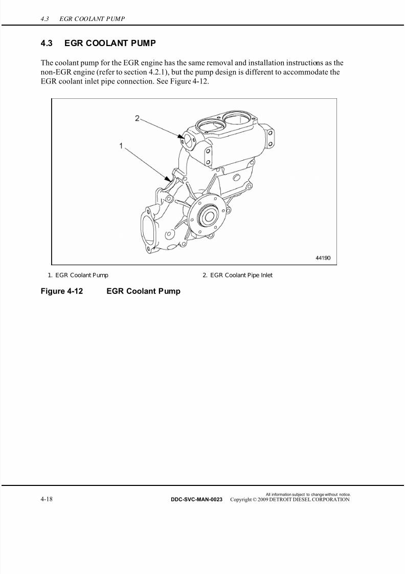
7/22/2019 Manual Mbe 4000 Taller
http://slidepdf.com/reader/full/manual-mbe-4000-taller 376/630
4.3 EGR COOLANT PUMP
4.3 EGR COOLANT PUMP
The coolant pump for the EGR engine has the same removal and installation instructions as the
non-EGR engine (refer to section 4.2.1), but the pump design is different to accommodate the
EGR coolant inlet pipe connection. See Figure 4-12.
1. EGR Coolant Pump 2. EGR Coolant Pipe Inlet
Figure 4-12 EGR Coolant Pump
All information subject to change without notice.
4-18 DDC-SVC-MAN-0023 Copyright © 2009 DETROIT DIESEL CORPORATION
7/22/2019 Manual Mbe 4000 Taller
http://slidepdf.com/reader/full/manual-mbe-4000-taller 377/630
MBE 4000 SERVICE MANUAL
4.4 FRONT IDLER AND TENSIONER SUPPORT
Perform the following procedures for removal and installation of the front idler and tensioner
support.
4.4.1 Front Idler and Tensioner Support Removal
Remove the front idler and tensioner support as follows:
1. Disconnect the batteries.
2. Release the tension on the main drive belt and fan belt. Set the belts aside.
3. Remove the upper alternator mounting bolt and the lower alternator mounting bolt. Slide
the alternator backwards (towards the rear of the engine).
4. Remove the belt tensioner from the front idler and tensioner support.
All information subject to change without notice.
DDC-SVC-MAN-0023 Copyright © 2009 DETROIT DIESEL CORPORATION 4-19

7/22/2019 Manual Mbe 4000 Taller
http://slidepdf.com/reader/full/manual-mbe-4000-taller 378/630
4.4 FRONT IDLER AND TENSIONER SUPPORT
5. Remove the support from the cylinder block. See Figure 4-13.
1. Lower Coolant Tube 5. Coolant Pump Housing
2. Mounting Bolt, Inlet P ipe 6. F ront Idler and Tensioner S upport
3. Inlet P ipe 7. Mounting Bolt, F ront Idler and Tensioner Support
4. Inlet Pipe Gasket
Figure 4-13 Front Idler and Tensioner Support (exploded view)
4.4.2 Front Idler and Tensioner Support Installation
Install the front idler and tenisoner support as follows:
1. Install the front idler and tensioner support on the cylinder block. Tighten the mounting
bolts 60 N·m (44 lb·ft).
2. Install the belt tensioner on the support.
All information subject to change without notice.
4-20 DDC-SVC-MAN-0023 Copyright © 2009 DETROIT DIESEL CORPORATION

7/22/2019 Manual Mbe 4000 Taller
http://slidepdf.com/reader/full/manual-mbe-4000-taller 379/630
MBE 4000 SERVICE MANUAL
3. Move the alternator forward and mount it on the engine, as removed.
4. Release the tension on the main belt tensioner and install the main drive belt. Release the
tension on the fan belt tensioner and install the fan belt.
5. Connect the batteries.
All information subject to change without notice.
DDC-SVC-MAN-0023 Copyright © 2009 DETROIT DIESEL CORPORATION 4-21
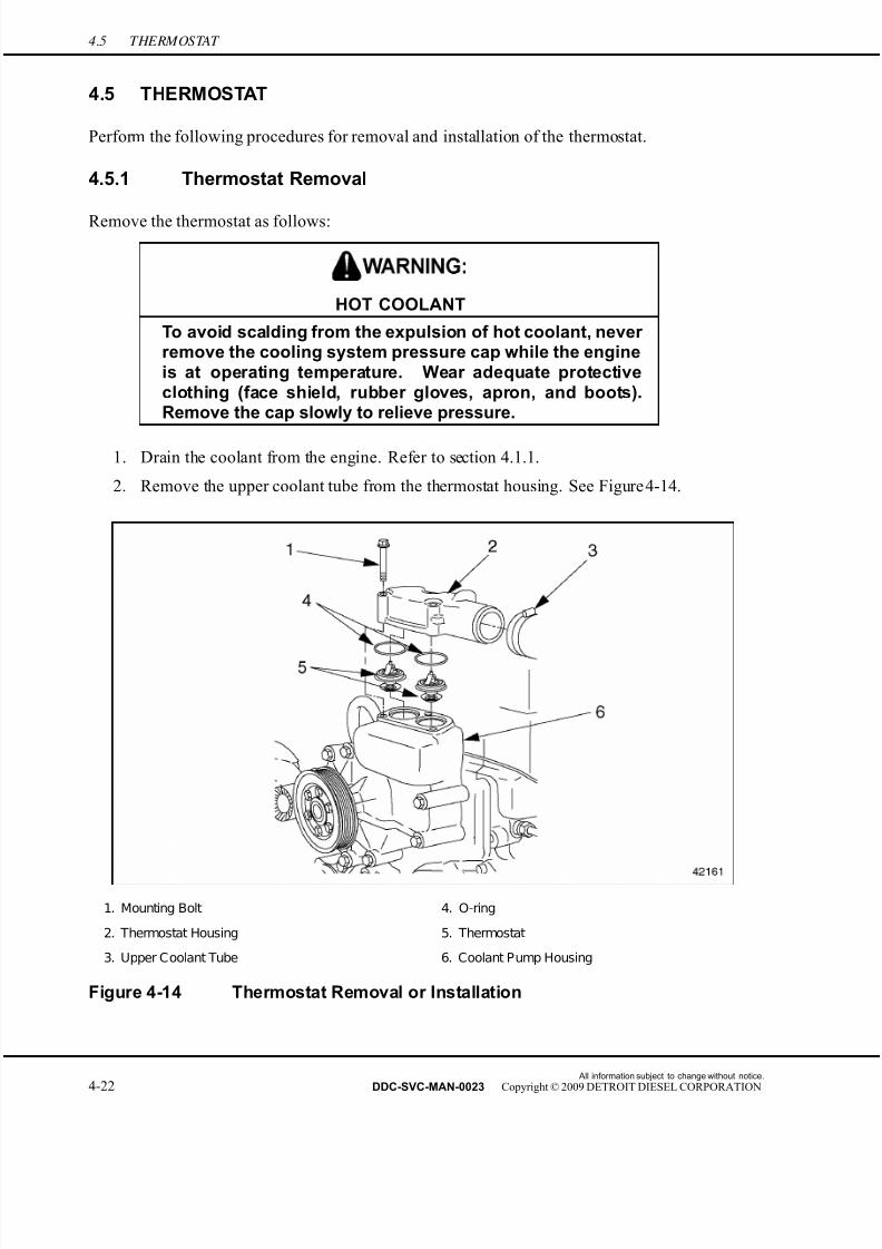
7/22/2019 Manual Mbe 4000 Taller
http://slidepdf.com/reader/full/manual-mbe-4000-taller 380/630
4.5 THERMOSTAT
4.5 THERMOSTAT
Perform the following procedures for removal and installation of the thermostat.
4.5.1 Thermostat Removal
Remove the thermostat as follows:
HOT COOLANT
To avoid scalding from the expulsion of hot coolant, never remove the cooling system pressure cap while the engineis at operating temperature. Wear adequate protectiveclothing (face shield, rubber gloves, apron, and boots).Remove the cap slowly to relieve pressure.
1. Drain the coolant from the engine. Refer to section 4.1.1.
2. Remove the upper coolant tube from the thermostat housing. See Figure 4-14.
1. Mounting Bolt 4. O-ring
2. Thermostat Housing 5. Thermostat
3. Upper Coolant Tube 6. Coolant Pump Housing
Figure 4-14 Thermostat Removal or Installation
All information subject to change without notice.
4-22 DDC-SVC-MAN-0023 Copyright © 2009 DETROIT DIESEL CORPORATION
7/22/2019 Manual Mbe 4000 Taller
http://slidepdf.com/reader/full/manual-mbe-4000-taller 381/630
MBE 4000 SERVICE MANUAL
3. Remove the mounting screws attaching the thermostat housing to the coolant pump
housing. Remove the thermostat housing.
NOTE:Catch any coolant that runs out of the upper coolant tube or coolant pump housing.
4. Remove the thermostats and O-rings from the coolant pump housing. Discard the O-rings.5. Check both thermostats for proper operation. For detailed procedures, refer to section
4.5.2.1. Replace any thermostat that fails one or more tests.
4.5.2 Thermostat Installation
Install the thermostat as follows:
1. Install a new O-ring on each thermostat.
2. Install the original and/or replacement thermostats.
3. Install the thermostat housing. Install the mounting bolts attaching the thermostat housingto the coolant pump housing. Tighten each mounting bolt 25 N·m (18 lb·ft). See Figure
4-14.
4. Install the upper coolant tube on the thermostat housing. Tighten the hose clamp until firm.
5. Fill the engine with coolant, and check for leaks and proper operation. Refer to section
4.1.1.
4.5.2.1 Thermostat Checking
Check the thermostat as follows:
1. Remove the thermostat from the coolant pump. Refer to section 4.5.1.
All information subject to change without notice.
DDC-SVC-MAN-0023 Copyright © 2009 DETROIT DIESEL CORPORATION 4-23
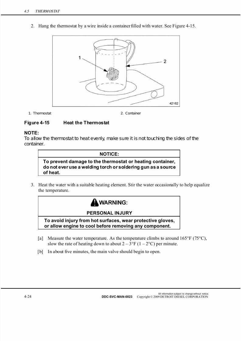
7/22/2019 Manual Mbe 4000 Taller
http://slidepdf.com/reader/full/manual-mbe-4000-taller 382/630
4.5 THERMOSTAT
2. Hang the thermostat by a wire inside a container filled with water. See Figure 4-15.
1. Thermostat 2. Container
Figure 4-15 Heat the Thermostat
NOTE: To allow the thermostat to heat evenly, make sure it is not touching the sides of thecontainer.
NOTICE:
To prevent damage to the thermostat or heating container,do not ever use a welding torch or soldering gun as a sourceof heat.
3. Heat the water with a suitable heating element. Stir the water occasionally to help equalize
the temperature.
PERSONAL INJURY
To avoid injury from hot surfaces, wear protective gloves,or allow engine to cool before removing any component.
[a] Measure the water temperature. As the temperature climbs to around 165°F (75°C),slow the rate of heating down to about 2 – 3°F (1 – 2°C) per minute.
[b] In about five minutes, the main valve should begin to open.
All information subject to change without notice.
4-24 DDC-SVC-MAN-0023 Copyright © 2009 DETROIT DIESEL CORPORATION

7/22/2019 Manual Mbe 4000 Taller
http://slidepdf.com/reader/full/manual-mbe-4000-taller 383/630
MBE 4000 SERVICE MANUAL
4. Continue to heat the water at this rate for about six to eight minutes until it reaches the
opening temperature of the main valve. If the main valve is not completely open, replace
the thermostat. See Figure 4-16.
1. Thermostat 3. Short Circuit Valve
2. Main Valve
Figure 4-16 Thermostat Lift
5. Check all the test values for the main valve listed in Table 4-5. If any of the values is
not met, replace the thermostat.
Description Temperature – °C (°F) Distance mm (in.)
Main Valve Starts To Open 81 – 85 (177 – 185) —Main Valve Fully Open 95 (203) —
Main Valve Minimum Lift — 8 (0.3)
Short Circuit Valve Fully Closed 92 (198) —
Short Circuit Valve Minimum Lift — 6 to 7.5 (0.24 to 0.295)
Table 4-5 Thermostat Test Values
[a] At the temperature of 85°C (185°F), check that the main valve has started to open.
[b] At the opening temperature of 95°C 203°F), check that the main valve is fully open.
[c] Check the minimum lift of the main valve at the opening temperature.
6. Check all the test values for the short circuit valve listed in Table 4-5. If any of the values
is not met, replace the thermostat.
[a] At the temperature of 92°C (198°F), check that the short circuit valve is fully closed.
[b] Check the minimum lift of the short circuit valve at the closing temperature.
All information subject to change without notice.
DDC-SVC-MAN-0023 Copyright © 2009 DETROIT DIESEL CORPORATION 4-25

7/22/2019 Manual Mbe 4000 Taller
http://slidepdf.com/reader/full/manual-mbe-4000-taller 384/630
4.5 THERMOSTAT
7. Install the original or replacement thermostat(s), as necessary, the upper coolant hose inlet,
and O-ring(s) on the coolant pump, as removed.
8. Fill the engine with coolant, as removed, and check for leaks and proper operation.
All information subject to change without notice.
4-26 DDC-SVC-MAN-0023 Copyright © 2009 DETROIT DIESEL CORPORATION
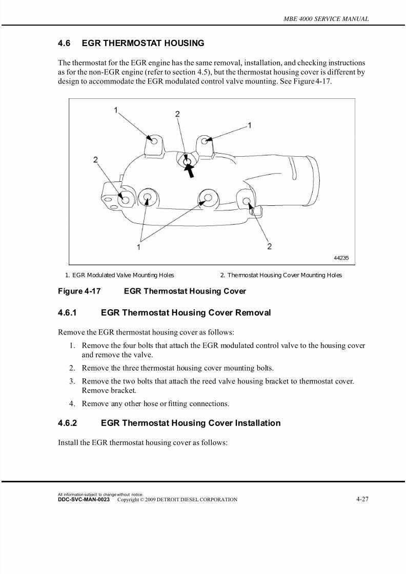
7/22/2019 Manual Mbe 4000 Taller
http://slidepdf.com/reader/full/manual-mbe-4000-taller 385/630
MBE 4000 SERVICE MANUAL
4.6 EGR THERMOSTAT HOUSING
The thermostat for the EGR engine has the same removal, installation, and checking i nstructions
as for the non-EGR engine (refer to section 4.5), but the thermostat housing cover is different by
design to accommodate the EGR modulated control valve mounting. See Figure 4-17.
1. EGR Modulated Valve Mounting Holes 2. Thermostat Housing Cover Mounting Holes
Figure 4-17 EGR Thermostat Housing Cover
4.6.1 EGR Thermostat Housing Cover Removal
Remove the EGR thermostat housing cover as follows:
1. Remove the four bolts that attach the EGR modulated control valve to the housing cover
and remove the valve.
2. Remove the three thermostat housing cover mounting bolts.
3. Remove the two bolts that attach the reed valve housing bracket to thermostat cover.
Remove bracket.
4. Remove any other hose or fitting connections.
4.6.2 EGR Thermostat Housing Cover Installation
Install the EGR thermostat housing cover as follows:
All information subject to change without notice.
DDC-SVC-MAN-0023 Copyright © 2009 DETROIT DIESEL CORPORATION 4-27

7/22/2019 Manual Mbe 4000 Taller
http://slidepdf.com/reader/full/manual-mbe-4000-taller 386/630
4.6 EGR THERMOSTAT HOUSING
1. Attach the thermostat housing cover to the thermostat housing using the three mounting
bolts. Install the first bolt where heavy arrow is pointing in graphic. See Figure 4-18.
Torque to 30 N·m (22 lb·ft).
1. EGR Modulated Valve Mounting Holes 2. Thermostat Housing Cover Mounting Holes
Figure 4-18 EGR Thermostat Housing Cover Installation
2. Install EGR modulated valve to thermostat housing cover using four bolts.
3. Attach reed valve housing bracket to thermostat cover.
4. Install any other hose or fitting connections.
All information subject to change without notice.
4-28 DDC-SVC-MAN-0023 Copyright © 2009 DETROIT DIESEL CORPORATION

7/22/2019 Manual Mbe 4000 Taller
http://slidepdf.com/reader/full/manual-mbe-4000-taller 387/630
MBE 4000 SERVICE MANUAL
4.7 COOLANT TEMPERATURE SENSOR
Perform the following procedures for removal and installation of the coolant temperature sensor.
4.7.1 Coolant Temperature Sensor Disassembly
Disassemble the coolant temperature sensor as follows:
HOT COOLANT
To avoid scalding from the expulsion of hot coolant, never remove the cooling system pressure cap while the engineis at operating temperature. Wear adequate protectiveclothing (face shield, rubber gloves, apron, and boots).Remove the cap slowly to relieve pressure.
1. Drain some coolant from the engine.
NOTE:It is not necessary to drain all the coolant fromthe engine to do this procedure. Enoughhas to be drained to prevent coolant from leaking out while the sensor is being changed.
2. Remove the engine trim panel.
3. Locate the temperature sensor behind the engine harness, between unit pumps #2 and
#3. See Figure 4-19.
1. Cylinder Block 3. Coolant Temperature Sensor
2. High-Pressure Fuel Line 4. Engine Harness
Figure 4-19 Coolant Temperature Sensor Location
All information subject to change without notice.
DDC-SVC-MAN-0023 Copyright © 2009 DETROIT DIESEL CORPORATION 4-29
7/22/2019 Manual Mbe 4000 Taller
http://slidepdf.com/reader/full/manual-mbe-4000-taller 388/630
4.7 COOLANT TEMPERATURE SENSOR
4. Remove the electrical connector from the sensor.
5. Unscrew the sensor from the wall of the cylinder block.
4.7.2 Coolant Temperature Sensor Assembly
Assemble the coolant temperature sensor as follows:
1. Screw the new sensor into the hole in the cylinder block, as removed.
2. Connect the electrical connector to the sensor. Make sure the connection is secure.
3. Install the engine trim panel.
4. Fill the engine with coolant, and check for leaks and proper operation.
All information subject to change without notice.
4-30 DDC-SVC-MAN-0023 Copyright © 2009 DETROIT DIESEL CORPORATION
7/22/2019 Manual Mbe 4000 Taller
http://slidepdf.com/reader/full/manual-mbe-4000-taller 389/630
MBE 4000 SERVICE MANUAL
4.A ADDITIONAL INFORMATION
Description Page
SP ECIFICATIONS ............................................................................................. 4-31Cooling System Overview .............................................................................. 4-32
Coolant Pump ................................................................................................. 4-33
Thermostat ..................................................................................................... 4-34
Coolant Sensor ............................................................................................... 4-34
SPECIFICATIONS
This section contains the specifications for servicing the engine.
All information subject to change without notice.
DDC-SVC-MAN-0023 Copyright © 2009 DETROIT DIESEL CORPORATION 4-31

7/22/2019 Manual Mbe 4000 Taller
http://slidepdf.com/reader/full/manual-mbe-4000-taller 390/630
Cooling System Overview
The coolant specifications are listed in Table 4-6. Listed in Table 4-7 are the cooling system
capacity figures. The coolant mixing ratio is listed in Table 4-8.
Type of Coolant Requirement
Fully -Formulated Ethylene Glycol* TMC RP-329 Type "A"
Water plus Corrosion Inhibitors Temperature mustnot fall below 32°F (0°C)
*Preferred coolant
Table 4-6 Coolant Specifications
Description Capacity in liters (Quarts)
Engine Coolant Capacity (all vehicles
Engine capacity* 30.0 (31.7)
Century Class and Columbia C ooling System Capacity
Total capacity† 57.4 (60.7)
Antifreeze quantity at 50 percent 28.7 (30.4)
Antifreeze quantity at 55 percent 31.6 (33.4)
Sterling A-Line and L-Line Cooling System Capacity
Total capacity 53.8 (56.8)
Antifreeze quantity at 50 percent 26.9 (28.4)
Antifreeze quantity at 55 percent 29.6 (31.3)
FL112 Cooling System Capacity
Total capacity 42.0 (44.4)
Antifreeze quantity at 50 percent 21.0 (22.2)
Antifreeze quantity at 55 percent 23.1 (24.4)
* Does not include capacity of cooling system.
†With 1200 sq. ft. radiator.
Table 4-7 Cooling System Capacity
Antifreeze Protection Down
to °F (°C)
Water Percentage by Volume Corrosion-Inhibiting Antifreeze
Percentage by Volume
-34 (-37) 50 50
-49 (-45) 40 Maximum 60
Table 4-8 Coolant Mixing Ratio
All information subject to change without notice.
4-32 DDC-SVC-MAN-0023 Copyright © 2009 DETROIT DIESEL CORPORATION

7/22/2019 Manual Mbe 4000 Taller
http://slidepdf.com/reader/full/manual-mbe-4000-taller 391/630
MBE 4000 SERVICE MANUAL
Coolant Pump
The torque values for the cooling system are listed in Table 4-9. The wear dimensions for the
coolant pump assembly are listed in Table 4-10. Listed in Table 4-11 is the critical dimension for
the coolant pump assembly.
Fastener Torque Value, mm (in.)
Coolant P ump Inlet P ipe Mounting Bolts 50 (37)
Coolant Pump Mounting Bolts 30 (22)
Coolant P ump Pulley Mounting Bolts 25 (18)
F ront I dler and Tensioner S upport M ounting Bolts 60 (44)
Thermostat Housing Mounting Bolts 25 (18)
Table 4-9 Cooling System Torque Values
Description Dimensions, mm (in.)
Drive Shaft Diameter (at the hub) 25.048 - 25.061 (0.9861 - 0.9867)
Hub Inside Diameter 24.995 - 25.008 (0.9841 - 0.9846)
Bearing Outside Diameter 54.981 - 54.994 (2.1646 - 2.1651)
Bearing Housing Diameter 54.930 - 54.960 (2.1626 - 2.1638)
Drive Shaft Diameter (at the impeller) 15.045 - 15.056 (0.5923 - 0.5928)
Impeller Inside Diameter 15.000 - 15.018 (0.5906 - 0.5913)
Impeller Outside Diameter 124 - 125 (4.88 - 4.92)
Impeller - Maximum O ut-of-Round 0.15 (0.0059)
Table 4-10 Coolant Pump Assembly Wear Dimensions
Dimension Description mm (in.)
A Gap between the Impeller and the
Coolant Pump Housing
0.6 - 1.0 (0.023 - 0.039)
Table 4-11 Critical Dimension for Coolant Pump Assembly
All information subject to change without notice.
DDC-SVC-MAN-0023 Copyright © 2009 DETROIT DIESEL CORPORATION 4-33
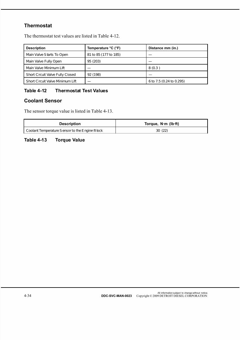
7/22/2019 Manual Mbe 4000 Taller
http://slidepdf.com/reader/full/manual-mbe-4000-taller 392/630
Thermostat
The thermostat test values are listed in Table 4-12.
Description Temperature °C (°F) Distance mm (in.)
Main Valve S tarts To Open 81 to 85 (177 to 185) —
Main Valve Fully Open 95 (203) —
Main Valve Minimum Lift — 8 (0.3 )
Short Circuit Valve Fully Closed 92 (198) —
Short Circuit Valve Minimum Lift — 6 to 7.5 (0.24 to 0.295)
Table 4-12 Thermostat Test Values
Coolant Sensor
The sensor torque value is listed in Table 4-13.
Description Torque, N·m (lb·ft)
Coolant Temperature S ensor to the E ngine B lock 30 (22)
Table 4-13 Torque Value
All information subject to change without notice.
4-34 DDC-SVC-MAN-0023 Copyright © 2009 DETROIT DIESEL CORPORATION

7/22/2019 Manual Mbe 4000 Taller
http://slidepdf.com/reader/full/manual-mbe-4000-taller 393/630
5 FUEL, LUBRICATING OIL, AND COOLANT
Section Page
5.1 FUEL ........................................................................................................ 5-3
5.2 LUBRICATING OIL .................................................................................. 5-5
5.3 COOLANT ................................................................................................ 5-7
5.A ADDITIONAL INFORMATION .................................................................. 5-13

7/22/2019 Manual Mbe 4000 Taller
http://slidepdf.com/reader/full/manual-mbe-4000-taller 394/630
All information subject to change without notice.
5-2 DDC-SVC-MAN-0023 Copyright © 2009 DETROIT DIESEL CORPORATION

7/22/2019 Manual Mbe 4000 Taller
http://slidepdf.com/reader/full/manual-mbe-4000-taller 395/630
MBE 4000 SERVICE MANUAL
5.1 FUEL
Use only commercially available vehicle diesel fuel. Grades such as marine diesel f uel, heating
oil, and others are not permissible.
NOTE:
Do not use fuel additives. Using fuel additives could affect your warranty.
If using diesel fuel with a high sulphur content, exceeding 0.5 percent by weight, change the
engine oil at shorter intervals.
NOTICE:
Fuel added from drums or cans could be contaminated. Thiscould lead to malfunctions in the fuel system. Always filter thefuel before adding it to the tank.
5.1.1 Flow Improvers
The effectiveness of flow improvers is not guar anteed with all fuels. Comply with the product
manufacturer's recommendations. Any authorized dealer can provide information on approved
flow improvers.
5.1.2 Kerosene
The addition of kerosene lowers the flash point of diesel
fuel. To prevent fire and risk of injuries due to burning,do not smoke or use open flames around fuel mixed withkerosene. Comply with all appropriate safety regulations.
Keep the quantity added as low as possible, bearing in mind the outside temperature. The addition
of five percent by volume of kerosene will improve the fuel's resistance to cold by about 1.8°F
(1°C). Never add more than 50 percent kerosene to the fuel.
For safety reasons, add the kerosene to the diesel only in the fuel tank. Add the kerosenefirst, then
the diesel. Run the engine for a short time to allow the mixture to reach all parts of the fuel system.
5.1.3 Winter Grade Diesel Fuel for Cold Weather
At low outside temperatures, paraf fin may separate from the diesel and affect its ability to flow
freely.
Avoid breakdowns caused by this problem (for example, blocked filters) by using cold-resistant
winter-grade diesel fuel with improved low-temperature flow characteristics. In most cases,
winter-grade f uel can be used without problems at cold outside temperatures.
All information subject to change without notice.
DDC-SVC-MAN-0023 Copyright © 2009 DETROIT DIESEL CORPORATION 5-3
7/22/2019 Manual Mbe 4000 Taller
http://slidepdf.com/reader/full/manual-mbe-4000-taller 396/630
5.1 FUEL
If using summer-grade fuel or a less cold-resistant winter grade, a flow improver or kerosene can
be added. The amount needed depends on the outside temperature.
NOTICE:
Do not add gasoline to diesel fuel or engine damage will result.
Flow improver or petroleum spirit must be mixed with diesel fuel before its flow characteristicshave been adversely affected by paraf fin separation. If changes have already been caused
by paraf fin separation, they can be corrected only by heating the entire fuel system. Do not
add anything to cold-resistant winter-grade diesel fuels. The fuel's low-temperature flow
characteristics could actually deteriorate with additives.
All information subject to change without notice.
5-4 DDC-SVC-MAN-0023 Copyright © 2009 DETROIT DIESEL CORPORATION
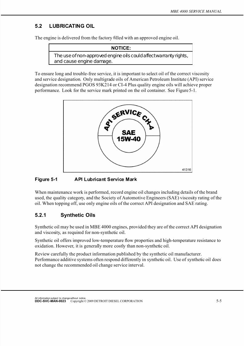
7/22/2019 Manual Mbe 4000 Taller
http://slidepdf.com/reader/full/manual-mbe-4000-taller 397/630
MBE 4000 SERVICE MANUAL
5.2 LUBRICATING OIL
The engine is delivered from the factory filled with an approved engine oil.
NOTICE:
The use ofnon-approved engine oils couldaffectwarranty rights,
and cause engine damage.
To ensure long and trouble-free service, it is important to select oil of the correct viscosity
and service designation. Only multigrade oils of American Petroleum Institute (API) service
designation recommend PGOS 93K214 or CI-4 Plus quality engine oils will achieve proper
performance. Look for the service mark printed on the oil container. See Figure 5-1.
Figure 5-1 API Lubricant Service Mark
When maintenance work is performed, record engine oil changes including details of the brand
used, the quality category, and the Society of Automotive Engineers (SAE) viscosity rating of the
oil. When topping off, use only engine oils of the correct API designation and SAE rating.
5.2.1 Synthetic Oils
Synthetic oil may be used in MBE 4000 engines, provided they are of the correct API designation
and viscosity, as required for non-synthetic oil.
Synthetic oil offers improved low-temperaturefl
ow properties and high-temperature resistance tooxidation. However, it is generally more costly than non-synthetic oil.
Review carefully the product information published by the synthetic oil manufacturer.
Performance additive systems often respond differently in synthetic oil. Use of synthetic oil does
not change the recommended oil change service interval.
All information subject to change without notice.
DDC-SVC-MAN-0023 Copyright © 2009 DETROIT DIESEL CORPORATION 5-5

7/22/2019 Manual Mbe 4000 Taller
http://slidepdf.com/reader/full/manual-mbe-4000-taller 398/630
5.2 LUBRICATING OIL
5.2.2 Low Viscosity Engine Oil for Cold Weather
When changing the engine oil, estimate the interval before your next oil change. Choose an oil
from the SAE viscosity class which corresponds to the outside temperatures anticipated during
this period of operation. See Figure 5-2.
Figure 5-2 Engine Oil Temperature Ranges
All information subject to change without notice.
5-6 DDC-SVC-MAN-0023 Copyright © 2009 DETROIT DIESEL CORPORATION
7/22/2019 Manual Mbe 4000 Taller
http://slidepdf.com/reader/full/manual-mbe-4000-taller 399/630
MBE 4000 SERVICE MANUAL
5.3 COOLANT
Coolant is a mixture of water and antifreeze. Under normal conditions, it is a mixtur e of 50
percent water and 50 percent antifreeze, but under extreme cold weather conditions, as much as
60 percent antifreeze can be added. For reasons of anticorrosion protection and to raise the boiling
point, the coolant must remain in the cooling system all year round.
Regardless of mileage, replace the coolant every two years since the degree of corrosion
protection gradually drops with time.
5.3.1 Fully Formulated Antifreeze
Antifreeze approved for use in the MBE 4000 engine is a mixt ure of glycol compound (ethylene
glycol), and corrosion inhibitors. Antifreeze containing glycol compounds and corrosion
inhibitors is known as fully-formulated antifreeze.
NOTE:Do not use propylene glycol.
Fully-formulated antifreeze has the following properties:
□ It protects the radiator and engine from freezing.
□ It provides protection against corrosion and cavitation for all components in the cooling
system.
□ It raises the boiling point of the coolant. This slows the rate of evaporation, avoiding
coolant loss at high temperatures.
5.3.2 Water
Water containing no additives is not suitable as a coolant, even if no antifreeze protection isneeded.
The water used in the coolant must comply with certain requirements, which are not always
satisfied by drinking water. If water quality is inadequate, the water must undergo suitable
treatment.
The following types of water are preferred for use in coolant:
□ Distilled water
□ Water purified by reverse osmosis
□ De-ionized water
All information subject to change without notice.
DDC-SVC-MAN-0023 Copyright © 2009 DETROIT DIESEL CORPORATION 5-7

7/22/2019 Manual Mbe 4000 Taller
http://slidepdf.com/reader/full/manual-mbe-4000-taller 400/630
5.3 COOLANT
NOTICE:
In some areas, tap water can contain high levels of dissolvedchlorides, sulfates, magnesium, and calcium, causing scaledeposits, sludge deposits and/or corrosion. These deposits candamage the coolant pump and allow the engine to overheat.
5.3.2.1 Coolant Specifications and Concentration
To avoid damage to the cooling system, use only an approved corrosion-inhibiting antifreeze.
Approved antifreeze must be fully-formulated and comply with the requirements of the Truck
Maintenance Council (TMC). Coolant specifications are listed in Table 5-1.
Type of Coolant Requirement
F ully-F ormulated E thylene Glycol TMC R P-329 Type "A"
Water plus Corrosion Inhibitors Temperature Must Not Fall Below 32°F (0°C)
Table 5-1 Coolant Specifications
When topping off the cooling system after a drop in the coolant level, the concentration of
corrosion-inhibiting antifreeze in the coolant must be 50 percent by volume. This affords
protection down to a temperatur e of –34°F (–37°C). The cooling mixing ratio is listed in Table 5-2.
NOTE:If the concentration is too low, there is risk of corrosion/cavitation in the cooling system.
Do not increase the proportion (mixing ratio) of corrosion-inhibiting antifreeze beyond 60 percent
by volume (this gives the maximum antifreeze protection). Further increases in the mixingratio would reduce the level of antifreeze protection and adversely affect the coolant's ability to
dissipate heat.
Antifreeze Protection Down
to °F (°C)
Water % by Volume Corrosion - Inhibiting
Antifreeze % by Volume
–34 (–37) 50 50
–62 (–52) 40 The cooling mix ratio is Max. 60
Table 5-2 Coolant Mixing Ratio
5.3.3 Supplemental Coolant Additives for Fully Formulated Coolant
The concentrations of some inhibitors will gradually deplete during normal engine operation.
SCAs replenish the protection for cooling system components. The coolant must be maintained
with the proper concentration of SCA. Detroit Diesel Power Cool maintenance SCAs are
recommended.
All information subject to change without notice.
5-8 DDC-SVC-MAN-0023 Copyright © 2009 DETROIT DIESEL CORPORATION
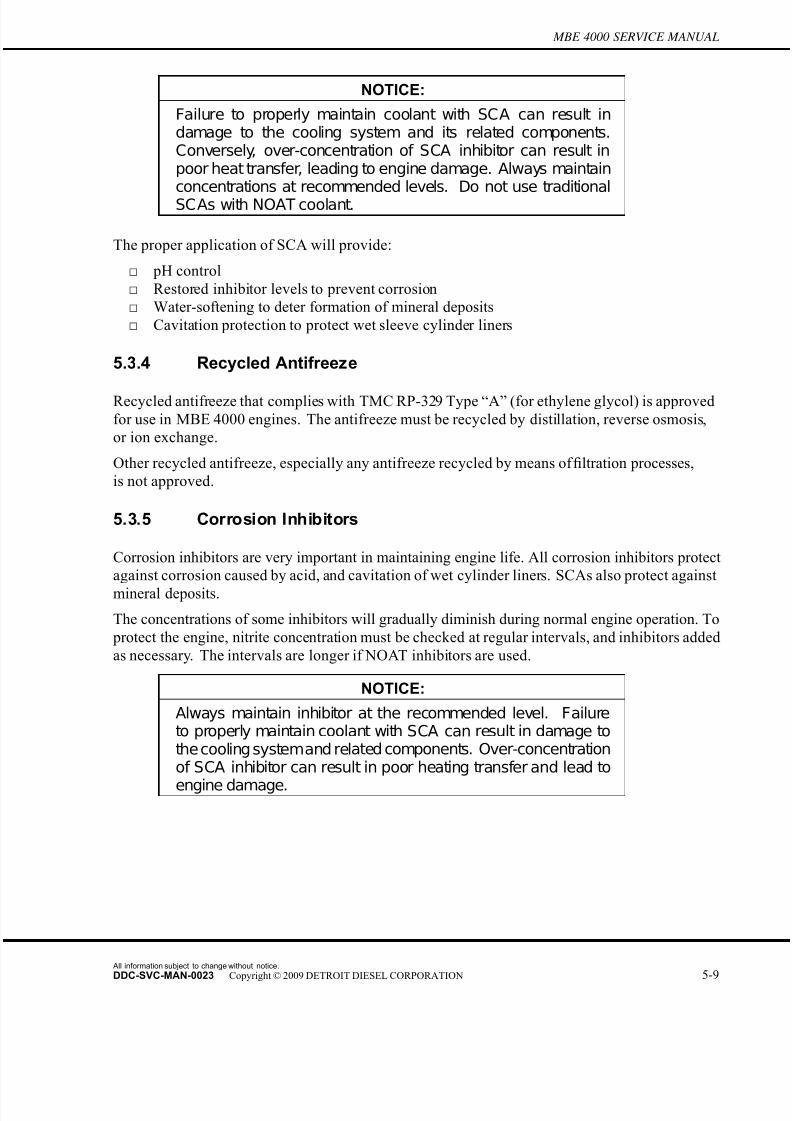
7/22/2019 Manual Mbe 4000 Taller
http://slidepdf.com/reader/full/manual-mbe-4000-taller 401/630
MBE 4000 SERVICE MANUAL
NOTICE:
Failure to properly maintain coolant with SCA can result indamage to the cooling system and its related components.Conversely, over-concentration of SCA inhibitor can result inpoor heat transfer, leading to engine damage. Always maintainconcentrations at recommended levels. Do not use traditionalSCAs with NOAT coolant.
The proper application of SCA will provide:
□ pH control
□ Restored inhibitor levels to prevent corrosion
□ Water-softening to deter formation of mineral deposits
□ Cavitation protection to protect wet sleeve cylinder liners
5.3.4 Recycled Antifreeze
Recycled antifreeze that complies with TMC RP-329 Type “A” (for ethylene glycol) is approved
for use in MBE 4000 engines. The antifreeze must be recycled by distillation, reverse osmosis,
or ion exchange.
Other recycled antifreeze, especially any antifreeze recycled by means of filtration processes,
is not approved.
5.3.5 Corrosion Inhibitors
Corrosion inhibitors are very important in maintaining engine life. All corrosion inhibitors protect
against corrosion caused by acid, and cavitation of wet cylinder liners. SCAs also protect against
mineral deposits.
The concentrations of some inhibitors will gradually diminish during normal engine operation. To
protect the engine, nitrite concentration must be checked at regular intervals, and inhibitors added
as necessary. The intervals are longer if NOAT inhibitors are used.
NOTICE:
Always maintain inhibitor at the recommended level. Failureto properly maintain coolant with SCA can result in damage tothe cooling systemand related components. Over-concentrationof SCA inhibitor can result in poor heating transfer and lead to
engine damage.
All information subject to change without notice.
DDC-SVC-MAN-0023 Copyright © 2009 DETROIT DIESEL CORPORATION 5-9
7/22/2019 Manual Mbe 4000 Taller
http://slidepdf.com/reader/full/manual-mbe-4000-taller 402/630
5.3 COOLANT
NOTICE:
Do not mix types of corrosion inhibitors. Do not add additionalinhibitors to new, fully-formulated antifreeze, or coolantcontaining new, fully-formulated antifreeze. This can causedeposits or dropout in the cooling system.
The following types of corrosion inhibitors are approved for use in MBE 4000 engines:
□ Supplemental Coolant Additives (SCAs)
□ Nitrated Organic Acid Technology (NOAT) Inhibitors
Corrosion inhibitors are very important in maintaining engine life. All corrosion inhibitors protect
against corrosion caused by acid, and cavitation of wet cylinder liners. SCAs also protect against
mineral deposits.
The concentrations of some inhibitors will gradually diminish during normal engine operation. To
protect the engine, nitrite concentration must be checked at regular intervals, and inhibitors added
as necessary. The intervals are longer if NOAT inhibitors are used.
NOTICE:
Always maintain inhibitor at the recommended level. Failureto properly maintain coolant with SCA can result in damage tothe cooling systemand related components. Over-concentrationof SCA inhibitor can result in poor heating transfer and lead toengine damage.
The following types of inhibitor must not be used in MBE 4000 engines:
□ Soluble oil additives cause poor heat transfer and lead to engine damage.
□ Chromate additives can lead to the build-up of "green slime" (chromium dioxide) in theengine, leading to engine damage.
5.3.5.1 Dropout
Excessive amounts of some corrosion inhibitors can cause a gel or crystalline deposit that reduces
both heat transfer and coolant flow. This deposit is called "dropout."
Dropout takes the color of the coolant when wet, but becomes a white or gray powder when dry.
It can pick up solid particles in the coolant and become gritty. It will cause premature wear of the
coolant pump seals and other components of the cooling system.
The wet gel can be removed using an alkaline (non-acid) cleaner containing either sodium nitriteor sodium tetraborate.
If the gel is allowed to dry, it is necessary to disassemble the engine and clean it with a caustic
solution, or physically clean the individual components.
All information subject to change without notice.
5-10 DDC-SVC-MAN-0023 Copyright © 2009 DETROIT DIESEL CORPORATION
7/22/2019 Manual Mbe 4000 Taller
http://slidepdf.com/reader/full/manual-mbe-4000-taller 403/630
MBE 4000 SERVICE MANUAL
5.3.6 Non-Approved Coolants
The following types of coolant are not approved for use in MBE 4000 engines:
□ Antifreeze or coolant containing phosphate can cause dropout, overheating, and damage to
coolant pump seals.
□ Automotive coolants offer no protection against liner pitting, and generally contain high
levels of phosphate and silicate.
□ Antifreeze based on methyl alcohol can damage the non-metallic components of the cooling
system. They are not suitable for use with diesel engines because of their low boiling point.
□ Antifreeze based on methoxy propanol is not compatible with the fluoroelastomer seals
used in the cooling system.
□ Glycol-based HVAC coolants contain phosphates which can deposit on hot internal engine
surfaces and reduce heat transfer.
5.3.7 Disposal
Coolants are biologically degradable substances.When disposing of used coolant, comply with local legal requirements and waste water
regulations.
Consult the local water supply authorities to determine the best method of disposal.
A modern engine coolant has complex tasks to perform. Do not allow any form of "reprocessing"
which consists only of mechanical purification.
5.3.8 Batteries
Batteries should receive more frequent maintenance and recharging during the cold season of the
year.
Careful maintenance and low current consumption will help to maintain the full battery charge.
Starting capacity drops severely in cold weather. For example, at 14°F (–10°C) starting capacity
is only about 60 percent of normal. If the engine is shut down or out of use for an extended
period of time, store the batteries out of the vehicle in a heated area if possible. Ensure good
ventilation when recharging.
All information subject to change without notice.
DDC-SVC-MAN-0023 Copyright © 2009 DETROIT DIESEL CORPORATION 5-11

7/22/2019 Manual Mbe 4000 Taller
http://slidepdf.com/reader/full/manual-mbe-4000-taller 404/630
5.3 COOLANT
All information subject to change without notice.
5-12 DDC-SVC-MAN-0023 Copyright © 2009 DETROIT DIESEL CORPORATION
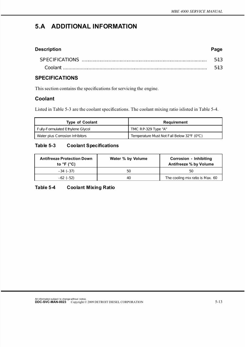
7/22/2019 Manual Mbe 4000 Taller
http://slidepdf.com/reader/full/manual-mbe-4000-taller 405/630
MBE 4000 SERVICE MANUAL
5.A ADDITIONAL INFORMATION
Description Page
SP ECIFICATIONS ............................................................................................. 5-13Coolant ........................................................................................................... 5-13
SPECIFICATIONS
This section contains the specifications for servicing the engine.
Coolant
Listed in Table 5-3 are the coolant specifications. The coolant mixing ratio islisted in Table 5-4.
Type of Coolant Requirement
F ully-F ormulated E thylene Glycol TMC R P-329 Type "A"
Water plus Corrosion Inhibitors Temperature Must Not Fall Below 32°F (0°C)
Table 5-3 Coolant Specifications
Antifreeze Protection Down
to °F (°C)
Water % by Volume Corrosion - Inhibiting
Antifreeze % by Volume
–34 (–37) 50 50
–62 (–52) 40 The cooling mix ratio is Max. 60
Table 5-4 Coolant Mixing Ratio
All information subject to change without notice.
DDC-SVC-MAN-0023 Copyright © 2009 DETROIT DIESEL CORPORATION 5-13

7/22/2019 Manual Mbe 4000 Taller
http://slidepdf.com/reader/full/manual-mbe-4000-taller 406/630
All information subject to change without notice.
5-14 DDC-SVC-MAN-0023 Copyright © 2009 DETROIT DIESEL CORPORATION
7/22/2019 Manual Mbe 4000 Taller
http://slidepdf.com/reader/full/manual-mbe-4000-taller 407/630
6 AIR INTAKE SYSTEM
Section Page
6.1 INTAKE MANIFOLD ................................................................................. 6-3
6.2 CHARGE PRE SSURE/TEMPERATURE SENSOR ................................. 6-5
6.3 TURBOCHARGER ................................................................................... 6-6
6.A ADDITIONAL INFORMATION .................................................................. 6-17

7/22/2019 Manual Mbe 4000 Taller
http://slidepdf.com/reader/full/manual-mbe-4000-taller 408/630
All information subject to change without notice.
6-2 DDC-SVC-MAN-0023 Copyright © 2009 DETROIT DIESEL CORPORATION
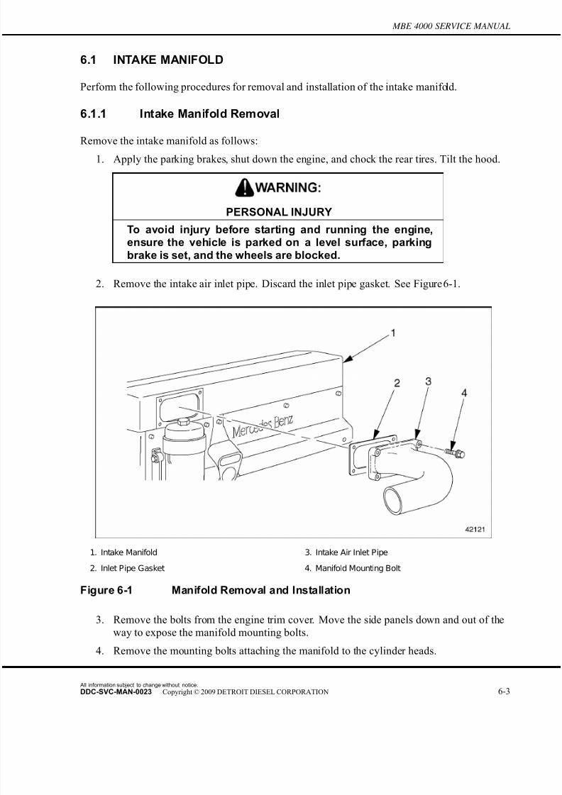
7/22/2019 Manual Mbe 4000 Taller
http://slidepdf.com/reader/full/manual-mbe-4000-taller 409/630
MBE 4000 SERVICE MANUAL
6.1 INTAKE MANIFOLD
Perform the following procedures for removal and installation of the intake manifold.
6.1.1 Intake Manifold Removal
Remove the intake manifold as follows:
1. Apply the parking brakes, shut down the engine, and chock the rear tires. Tilt the hood.
PERSONAL INJURY
To avoid injury before starting and running the engine,ensure the vehicle is parked on a level surface, parkingbrake is set, and the wheels are blocked.
2. Remove the intake air inlet pipe. Discard the inlet pipe gasket. See Figure 6-1.
1. Intake Manifold 3. Intake Air Inlet Pipe
2. Inlet Pipe Gasket 4. Manifold Mounting Bolt
Figure 6-1 Manifold Removal and Installation
3. Remove the bolts from the engine trim cover. Move the side panels down and out of the
way to expose the manifold mounting bolts.
4. Remove the mounting bolts attaching the manifold to the cylinder heads.
All information subject to change without notice.
DDC-SVC-MAN-0023 Copyright © 2009 DETROIT DIESEL CORPORATION 6-3

7/22/2019 Manual Mbe 4000 Taller
http://slidepdf.com/reader/full/manual-mbe-4000-taller 410/630
6.1 INTAKE MANIFOLD
5. Move the manifold out enough to expose the sensor attached to the back of the manifold.
Disconnect the electrical connector from the socket on the charge air pressure/temperature
sensor. See Figure 6-2.
1. Electrical Connector 3. Sensor Mounting Bolt
2. Intake Manifold Pressure/Temperature Sensor 4. Intake Manifold
Figure 6-2 Sensor Removal
6. Remove the charge air manifold from the cylinder heads.
7. Remove the charge air manifold gaskets. Clean any bits of sealant material from the
manifold and the mating surfaces on the cylinder heads.
6.1.2 Intake Manifold Installation
Install the intake manifold as follows:
1. Place new manifold gaskets on the heads.
2. Connect the electrical connector to the charge air pressure/temperature sensor.
3. Install the manifold on the cylinder head. Tighten the mounting bolts 40 N·m (30 lb·ft).
4. Install the engine trim cover side panels, as removed.
5. Install the charge air inlet pipe, with a new gasket, on the charge air manifold.
6. Lower the hood and remove the chocks from the rear tires.
All information subject to change without notice.
6-4 DDC-SVC-MAN-0023 Copyright © 2009 DETROIT DIESEL CORPORATION
7/22/2019 Manual Mbe 4000 Taller
http://slidepdf.com/reader/full/manual-mbe-4000-taller 411/630
MBE 4000 SERVICE MANUAL
6.2 CHARGE PRESSURE/TEMPERATURE SENSOR
Perform the following procedures for removal and installation of the charge pressure/temperature
sensor.
6.2.1 Charge Pressure/Temperature Sensor Removal
Remove the charge pressure/temperature sensor as follows:
1. Apply the parking brakes, shut down the engine, and chock the rear tires. Tilt the hood.
PERSONAL INJURY
To avoid injury before starting and running the engine,ensure the vehicle is parked on a level surface, parkingbrake is set, and the wheels are blocked.
2. Remove the #2 cylinder head cover.
3. Disconnect the electrical connector.
4. Remove the fasteners that attach the pressure/temperature sensor, then remove the sensor.
6.2.2 Charge Pressure/Temperature Sensor Installation
Install the charge pressure/temperature sensor as follows:
1. Install the pressure/temperature sensor. Tighten the fasteners 10 N·m (7 lb·ft).
2. Connect the electrical connector.
3. Install the #2 cylinder head cover.
4. Lower the hood and remove the chocks from the rear tires.
All information subject to change without notice.
DDC-SVC-MAN-0023 Copyright © 2009 DETROIT DIESEL CORPORATION 6-5

7/22/2019 Manual Mbe 4000 Taller
http://slidepdf.com/reader/full/manual-mbe-4000-taller 412/630
6.3 TURBOCHARGER
6.3 TURBOCHARGER
Perform the following procedures for removal and installation of the turbocharger .
6.3.1 Turbocharger Inspection
Inspect the turbocharger as follows:
1. Chock the rear tires and lift the hood.
PERSONAL INJURY
To avoid injury before starting and running the engine,ensure the vehicle is parked on a level surface, parkingbrake is set, and the wheels are blocked.
PERSONAL INJURY
Diesel engine exhaust and some of its constituents areknown to the State of California to cause cancer, birthdefects, and other reproductive harm.□ Always start and operate an engine in a well ventilated
area.□ If operating an engine in an enclosed area, vent the
exhaust to the outside.□ Do not modify or tamper with the exhaust system or
emission control system.
2. Place the transmission in neutral and start the engine.
PERSONAL INJURY
To avoid injury, use care when working around moving beltsand rotating parts on the engine.
3. Check the turbocharger for unusual noises and excessive vibration.
NOTE:Unusual noises and excessive vibration can be caused by damage to the turbochargerwheels, or by leaks in the charge-air piping.
All information subject to change without notice.
6-6 DDC-SVC-MAN-0023 Copyright © 2009 DETROIT DIESEL CORPORATION
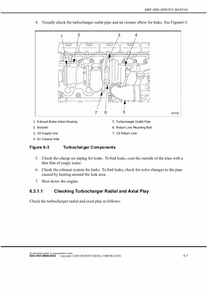
7/22/2019 Manual Mbe 4000 Taller
http://slidepdf.com/reader/full/manual-mbe-4000-taller 413/630
MBE 4000 SERVICE MANUAL
4. Visually check the turbocharger outlet pipe and air cleaner elbow for leaks. See Figure 6-3.
1. Exhaust Brake Valve Housing 5. Turbocharger Outlet Pipe
2. Bracket 6. Return Line Mounting Bolt
3. Oil Supply Line 7. Oil Return Line
4. Air Cleaner Inlet
Figure 6-3 Turbocharger Components
5. Check the charge air piping for leaks. To find leaks, coat the outside of the pipe with a
thin film of soapy water.
6. Check the exhaust system for leaks. To find leaks, check for color changes to the pipe
caused by heating around the leak area.
7. Shut down the engine.
6.3.1.1 Checking Turbocharger Radial and Axial Play
Check the turbocharger radial and axial play as follows:
All information subject to change without notice.
DDC-SVC-MAN-0023 Copyright © 2009 DETROIT DIESEL CORPORATION 6-7

7/22/2019 Manual Mbe 4000 Taller
http://slidepdf.com/reader/full/manual-mbe-4000-taller 414/630
6.3 TURBOCHARGER
1. Remove the exhaust brake valve housing to expose the turbocharger wheel. See Figure 6-4.
1. Turbocharger Wheel 2. Compressor Wheel
Figure 6-4 Location of Wheels
2. Remove the exhaust brake valve housing and the air cleaner inlet pipe to expose both
wheels. See Figure 6-4.
3. Check both wheels for damage to the blade caused by dirt, debris, and other foreign
matter in the turbocharging air system. See Figure 6-5 for the turbocharger wheel and
see Figure 6-6 for the compressor wheel.
All information subject to change without notice.
6-8 DDC-SVC-MAN-0023 Copyright © 2009 DETROIT DIESEL CORPORATION

7/22/2019 Manual Mbe 4000 Taller
http://slidepdf.com/reader/full/manual-mbe-4000-taller 415/630
MBE 4000 SERVICE MANUAL
1. Turbocharger Housing 3. Blade
2. Rotor Shaft
Figure 6-5 Turbocharger Wheel
1. Turbocharger Housing 3. Blade
2. Rotor Shaft
Figure 6-6 Compressor Wheel
All information subject to change without notice.
DDC-SVC-MAN-0023 Copyright © 2009 DETROIT DIESEL CORPORATION 6-9
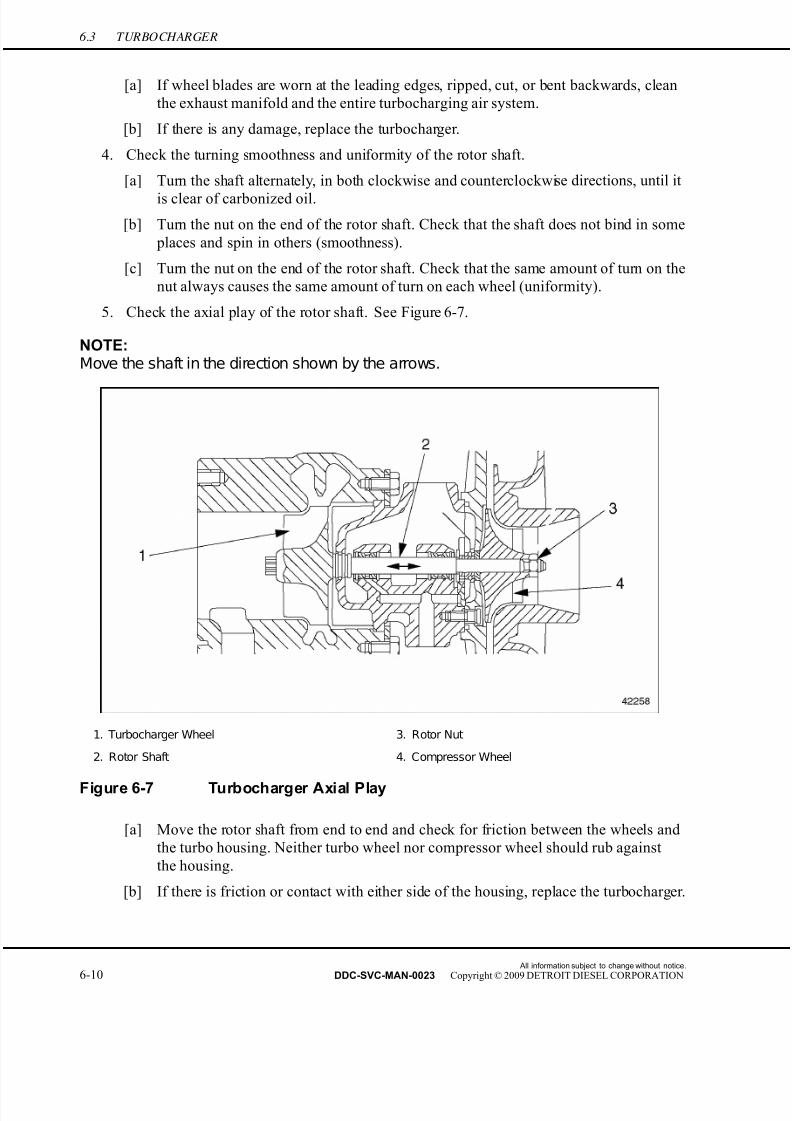
7/22/2019 Manual Mbe 4000 Taller
http://slidepdf.com/reader/full/manual-mbe-4000-taller 416/630
6.3 TURBOCHARGER
[a] If wheel blades are worn at the leading edges, ripped, cut, or bent backwards, clean
the exhaust manifold and the entire turbocharging air system.
[b] If there is any damage, replace the turbocharger.
4. Check the turning smoothness and uniformity of the rotor shaft.
[a] Turn the shaft alternately, in both clockwise and counterclockwise directions, until it
is clear of carbonized oil.
[b] Turn the nut on the end of the rotor shaft. Check that the shaft does not bind in some
places and spin in others (smoothness).
[c] Turn the nut on the end of the rotor shaft. Check that the same amount of turn on the
nut always causes the same amount of turn on each wheel (uniformity).
5. Check the axial play of the rotor shaft. See Figure 6-7.
NOTE:Move the shaft in the direction shown by the arrows.
1. Turbocharger Wheel 3. Rotor Nut
2. Rotor Shaft 4. Compressor Wheel
Figure 6-7 Turbocharger Axial Play
[a] Move the rotor shaft from end to end and check for friction between the wheels and
the turbo housing. Neither turbo wheel nor compressor wheel should rub against
the housing.
[b] If there is friction or contact with either side of the housing, replace the turbocharger.
All information subject to change without notice.
6-10 DDC-SVC-MAN-0023 Copyright © 2009 DETROIT DIESEL CORPORATION

7/22/2019 Manual Mbe 4000 Taller
http://slidepdf.com/reader/full/manual-mbe-4000-taller 417/630
MBE 4000 SERVICE MANUAL
6. Check the radial play of the rotor shaft. See Figure 6-8.
NOTE:Move the shaft in the direction shown by the arrows.
1. Turbocharger Wheel 3. Rotor Nut
2. Rotor Shaft 4. Compressor Wheel
Figure 6-8 Turbocharger Radial Play
[a] Move the rotor shaft from side to side and check for friction between the wheels and
the turbo housing. Neither turbo wheel nor compressor wheel should rub against
the housing.
[b] If there is friction or contact with either side of the housing, replace the turbocharger.
7. Install the air cleaner pipe.
8. Install the exhaust brake valve housing.
9. Lower the hood and remove the chocks from the rear tires.
6.3.2 Turbocharger Removal
Remove the turbocharger as follows:
1. Apply the parking brakes, shut down the engine, and chock the rear tires. Tilt the hood.
All information subject to change without notice.
DDC-SVC-MAN-0023 Copyright © 2009 DETROIT DIESEL CORPORATION 6-11
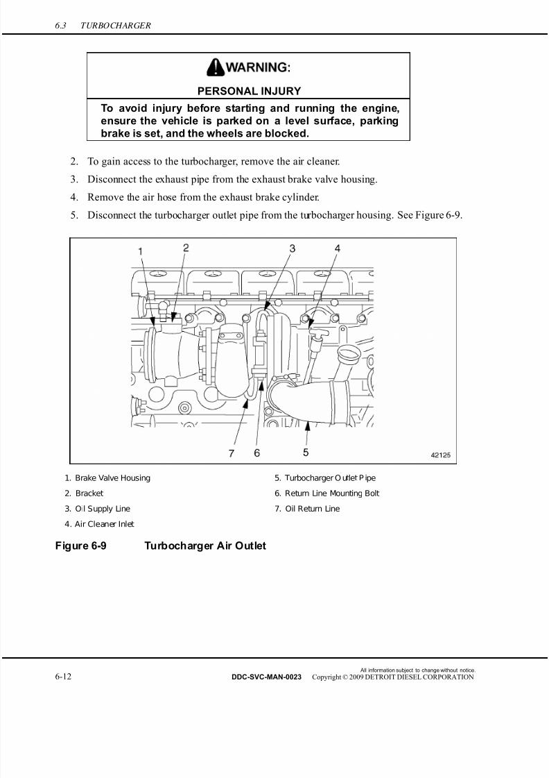
7/22/2019 Manual Mbe 4000 Taller
http://slidepdf.com/reader/full/manual-mbe-4000-taller 418/630
6.3 TURBOCHARGER
PERSONAL INJURY
To avoid injury before starting and running the engine,ensure the vehicle is parked on a level surface, parking
brake is set, and the wheels are blocked.
2. To gain access to the turbocharger, remove the air cleaner.
3. Disconnect the exhaust pipe from the exhaust brake valve housing.
4. Remove the air hose from the exhaust brake cylinder.
5. Disconnect the turbocharger outlet pipe from the turbocharger housing. See Figure 6-9.
1. Brake Valve Housing 5. Turbocharger O utlet P ipe
2. Bracket 6. Return Line Mounting Bolt
3. Oil Supply Line 7. Oil Return Line
4. Air Cleaner Inlet
Figure 6-9 Turbocharger Air Outlet
All information subject to change without notice.
6-12 DDC-SVC-MAN-0023 Copyright © 2009 DETROIT DIESEL CORPORATION

7/22/2019 Manual Mbe 4000 Taller
http://slidepdf.com/reader/full/manual-mbe-4000-taller 419/630
MBE 4000 SERVICE MANUAL
6. Disconnect the air intake elbow from the turbocharger. See Figure 6-10.
1. Turbocharger 4. Turbocharger Outlet Line
2. Air Cleaner P ipe 5. Constant-Torque Clamp
3. Air Intake Elbow 6. Charge Air Cooler
Figure 6-10 Turbocharger Air Intake
7. Remove the oil return line from the turbocharger and the cylinder block.
[a] Remove the two bolts attaching the oil return line to the turbocharger. Discard the
gasket.
[b] Remove the banjo bolt attaching the oil return line to the cylinder block. Discard
the two seal rings.
All information subject to change without notice.
DDC-SVC-MAN-0023 Copyright © 2009 DETROIT DIESEL CORPORATION 6-13

7/22/2019 Manual Mbe 4000 Taller
http://slidepdf.com/reader/full/manual-mbe-4000-taller 420/630
6.3 TURBOCHARGER
8. Remove the oil supply line from the turbocharger and the cylinder block. See Figure 6-11.
1. Seal Ring 3. Oil Supply Line
2. Banjo Fitting 4. Banjo Bolt
Figure 6-11 Oil Supply Line Fasteners
[a] Remove the two bolts attaching the oil supply line to the turbocharger. Discard
the gasket.
[b] Remove the banjo bolt attaching the oil supply line to the cylinder block. Discard
the two seal rings.
9. Remove the nuts that attach the turbocharger to the exhaust manifold. Remove the
turbocharger and exhaust brake valve housing.
10. Remove the exhaust brake valve housing from the turbocharger (if needed).
6.3.3 Turbocharger Installation
Install the turbocharger as follows:
1. Inspect the turbo inlet hose, turbocharger outlet pipe, and the oil supply and return lines
for restrictions or foreign objects.
2. Using new nuts, install the exhaust brake valve housing on the turbocharger (if removed).
Tighten the nuts 50 N·m (37 lb·ft).
All information subject to change without notice.
6-14 DDC-SVC-MAN-0023 Copyright © 2009 DETROIT DIESEL CORPORATION

7/22/2019 Manual Mbe 4000 Taller
http://slidepdf.com/reader/full/manual-mbe-4000-taller 421/630
MBE 4000 SERVICE MANUAL
3. Install the turbocharger on the exhaust manifold. listed in Table 6-1 are the torque values.
Description N·m (lb·ft)
E xhaust Brake Valve Housing to Turbocharger 50 (37)
Heat Shield Mounting Bolts 25 (18)
Turbocharger to Exhaust Manifold 50 (37) Turbocharger Oil Return Line Mounting Bolts 25 (18)
Turbocharger Oil Line Banjo Bolts 35 (26)
Turbocharger Oil Supply Line Mounting Bolts 25 (18)
Turbocharger Oil Return Line Connection 50 (37)
Turbocharger Oil Return Line Banjo Bolt 120 (88)
Table 6-1 Turbocharger Torque Values
[a] Coat four new prevailing torque locknuts with a light coating of high temperature
grease.
[b] Make sure that the mating surfaces of the turbocharger and the exhaust manifold
are clean and free of damage.
[c] Position the turbocharger over the mounting studs on the exhaust manifold.
[d] Install the nuts and tighten them 50 N·m (37 lb·ft).
4. Attach the oil return line to the turbocharger and the cylinder block. Listed in Table
6-1 are the torque values.
[a] Install a new gasket where the end flange of the return line meets the turbocharger.
[b] Install the mounting bolts through the holes in the endfl
ange. Tighten them 25 N·m(18 lb·ft).
[c] Install two new seal rings on the banjo fitting at the other end of the return line.
[d] Install the banjo bolt attaching the return line to the engine oil return inlet. Tighten
the bolt 35 N·m (26 lb·ft).
5. Fill the bearing housing with clean engine oil through the oil inlet port. Turn the
turbocharger wheel several times to coat the bearings with oil.
NOTE:If the turbocharger wheel cannot be spun freely by hand or if there is any indication of
rubbing or scraping, determine the reason before starting the engine. One cause of wheel rubbing is a misaligned turbocharger housing.
6. Refill the oil inlet port and connect the oil supply line. listed in Table 6-1 are the torque
values.
[a] Install a new gasket where the end flange of the supply line meets the turbocharger.
All information subject to change without notice.
DDC-SVC-MAN-0023 Copyright © 2009 DETROIT DIESEL CORPORATION 6-15
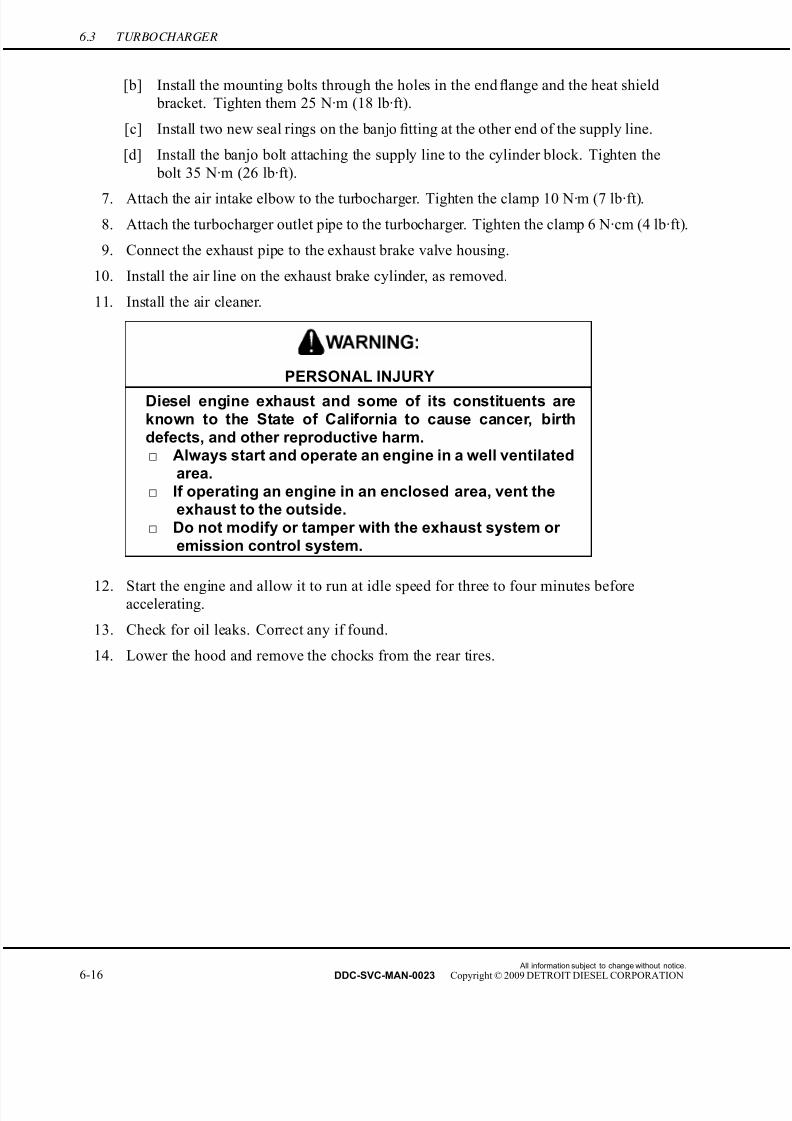
7/22/2019 Manual Mbe 4000 Taller
http://slidepdf.com/reader/full/manual-mbe-4000-taller 422/630
6.3 TURBOCHARGER
[b] Install the mounting bolts through the holes in the end flange and the heat shield
bracket. Tighten them 25 N·m (18 lb·ft).
[c] Install two new seal rings on the banjo fitting at the other end of the supply line.
[d] Install the banjo bolt attaching the supply line to the cylinder block. Tighten the
bolt 35 N·m (26 lb·ft).
7. Attach the air intake elbow to the turbocharger. Tighten the clamp 10 N·m (7 lb·ft).
8. Attach the turbocharger outlet pipe to the turbocharger. Tighten the clamp 6 N·cm (4 lb·ft).
9. Connect the exhaust pipe to the exhaust brake valve housing.
10. Install the air line on the exhaust brake cylinder, as removed.
11. Install the air cleaner.
PERSONAL INJURY
Diesel engine exhaust and some of its constituents areknown to the State of California to cause cancer, birthdefects, and other reproductive harm.□ Always start and operate an engine in a well ventilated
area.□ If operating an engine in an enclosed area, vent the
exhaust to the outside.□ Do not modify or tamper with the exhaust system or
emission control system.
12. Start the engine and allow it to run at idle speed for three to four minutes beforeaccelerating.
13. Check for oil leaks. Correct any if found.
14. Lower the hood and remove the chocks from the rear tires.
All information subject to change without notice.
6-16 DDC-SVC-MAN-0023 Copyright © 2009 DETROIT DIESEL CORPORATION
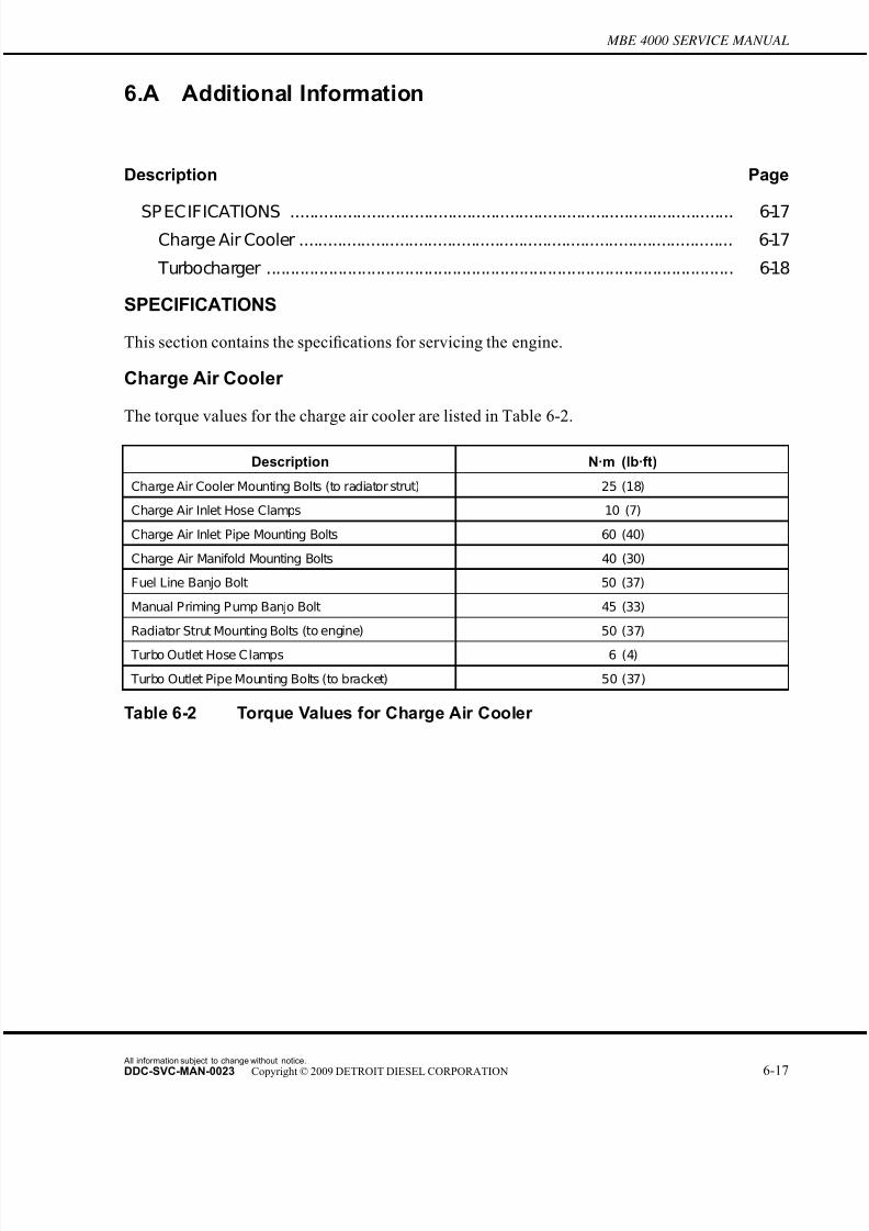
7/22/2019 Manual Mbe 4000 Taller
http://slidepdf.com/reader/full/manual-mbe-4000-taller 423/630
MBE 4000 SERVICE MANUAL
6.A Additional Information
Description Page
SP ECIFICATIONS ............................................................................................. 6-17Charge Air Cooler ........................................................................................... 6-17
Turbocharger .................................................................................................. 6-18
SPECIFICATIONS
This section contains the specifications for servicing the engine.
Charge Air Cooler
The torque values for the charge air cooler are listed in Table 6-2.
Description N·m (lb·ft)
Charge Air Cooler Mounting Bolts (to radiator strut) 25 (18)
Charge Air Inlet Hose Clamps 10 (7)
Charge Air Inlet Pipe Mounting Bolts 60 (40)
Charge Air Manifold Mounting Bolts 40 (30)
Fuel Line Banjo Bolt 50 (37)
Manual Priming Pump Banjo Bolt 45 (33)
Radiator Strut Mounting Bolts (to engine) 50 (37)
Turbo Outlet Hose Clamps 6 (4)
Turbo Outlet Pipe Mounting Bolts (to bracket) 50 (37)
Table 6-2 Torque Values for Charge Air Cooler
All information subject to change without notice.
DDC-SVC-MAN-0023 Copyright © 2009 DETROIT DIESEL CORPORATION 6-17
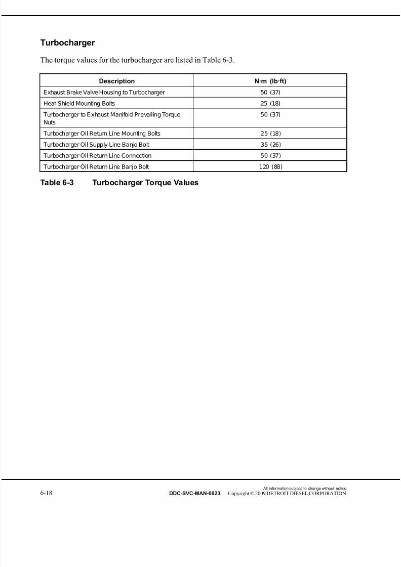
7/22/2019 Manual Mbe 4000 Taller
http://slidepdf.com/reader/full/manual-mbe-4000-taller 424/630
Turbocharger
The torque values for the turbocharger are listed in Table 6-3.
Description N·m (lb·ft)
Exhaust Brake Valve Housing to Turbocharger 50 (37)
Heat Shield Mounting Bolts 25 (18)
Turbocharger to E xhaust Manifold Prevailing Torque
Nuts
50 (37)
Turbocharger Oil Return Line Mounting Bolts 25 (18)
Turbocharger Oil Supply Line Banjo Bolt 35 (26)
Turbocharger Oil Return Line Connection 50 (37)
Turbocharger Oil Return Line Banjo Bolt 120 (88)
Table 6-3 Turbocharger Torque Values
All information subject to change without notice.
6-18 DDC-SVC-MAN-0023 Copyright © 2009 DETROIT DIESEL CORPORATION

7/22/2019 Manual Mbe 4000 Taller
http://slidepdf.com/reader/full/manual-mbe-4000-taller 425/630
7 EXHAUST SYSTEM
Section Page
7.1 EXHAUST MANIFOLD ............................................................................. 7-3
7.2 EXHAUST BRAKE ASSEMBLY ............................................................... 7-6
7.3 EGR EXHAUST MANIFOLD .................................................................... 7-14
7.4 EGR COOLER AND COOLER SUPP ORT BRACKET ............................ 7-26
7.5 EGR CONTROL VALVE, GAS OUTLET PIPE, AND GAS MIXER .......... 7-47
7.6 EPV (ELECTRONIC PROPORTIONAL VALVE) AND WABCO®AIR
SOLENOID VALVE ................................................................................... 7-54
7.7 HENGST BREATHER FILTER ................................................................. 7-58
7.A ADDITIONAL INFORMATION .................................................................. 7-67

7/22/2019 Manual Mbe 4000 Taller
http://slidepdf.com/reader/full/manual-mbe-4000-taller 426/630
All information subject to change without notice.
7-2 DDC-SVC-MAN-0023 Copyright © 2009 DETROIT DIESEL CORPORATION
7/22/2019 Manual Mbe 4000 Taller
http://slidepdf.com/reader/full/manual-mbe-4000-taller 427/630
MBE 4000 SERVICE MANUAL
7.1 EXHAUST MANIFOLD
Perform the following procedures for removal and installation of the exhaust manif old:
7.1.1 Exhaust Manifold Removal
Remove the exhaust manifold as follows:
1. Disconnect the batteries and tilt the hood.
2. Remove the turbocharger from the exhaust manifold. Refer to section 6.3.2.
All information subject to change without notice.
DDC-SVC-MAN-0023 Copyright © 2009 DETROIT DIESEL CORPORATION 7-3

7/22/2019 Manual Mbe 4000 Taller
http://slidepdf.com/reader/full/manual-mbe-4000-taller 428/630
7.1 EXHAUST MANIFOLD
3. Loosen all the exhaust manifold mounting bolts, but do not remove them yet. See Figure
7-1.
1. Exhaust Manifold 4. Spacer
2. Mounting Bolt 5. Gasket
3. Turbocharger 6. Cylinder Heads
Figure 7-1 Exhaust Manifold Removal and Installation
4. Remove the exhaust manifold components from each cylinder head.[a] Remove each mounting bolt and spacer from the exhaust manifold and each cylinder
head.
[b] Remove the spacer from each mounting bolt.
[c] Remove the exhaust manifold.
All information subject to change without notice.
7-4 DDC-SVC-MAN-0023 Copyright © 2009 DETROIT DIESEL CORPORATION
7/22/2019 Manual Mbe 4000 Taller
http://slidepdf.com/reader/full/manual-mbe-4000-taller 429/630
MBE 4000 SERVICE MANUAL
5. Remove and discard the gaskets from the exhaust port on each cylinder head. Clean any
bits of adhering gasket material from the exhaust manifold and the exhaust ports.
7.1.2 Exhaust Manifold Installation
Install the exhaust manifold as follows:
1. Install a gasket on each exhaust port. Fasten the gasket to the engine by installing one
mounting bolt on the forward side of each exhaust port.
2. Position the exhaust manifold next to the heads, and install it by sliding the manifold to
the right until it comes to rest on the bolts that were installed in the previous step.
3. Line up each gasket and install the remaining bolt and spacer on each exhaust port.
NOTE:Make sure that each gasket is properly aligned before tightening the mounting bolts onthat exhaust port.
4. Tighten each of the mounting bolts to 50 N·m (37 lb·ft).
5. Install the turbocharger on the mounting studs on the exhaust manifold. Refer to section
6.3.3.
6. Connect the batteries and lower the hood.
PERSONAL INJURY
Diesel engine exhaust and some of its constituents are
known to the State of California to cause cancer, birthdefects, and other reproductive harm.□ Always start and operate an engine in a well ventilated
area.□ If operating an engine in an enclosed area, vent the
exhaust to the outside.□ Do not modify or tamper with the exhaust system or
emission control system.
7. Start the engine and make sure there is oil pressure. Shut down the engine and check
for leaks.
All information subject to change without notice.
DDC-SVC-MAN-0023 Copyright © 2009 DETROIT DIESEL CORPORATION 7-5

7/22/2019 Manual Mbe 4000 Taller
http://slidepdf.com/reader/full/manual-mbe-4000-taller 430/630
7.2 EXHAUST BRAKE ASSEMBLY
7.2 EXHAUST BRAKE ASSEMBLY
Engine braking is controlled by a pneumatically-operated exhaust brake on the turbocharger and
by a constant-throttle system. For greater braking power, an optional turbo brake is available.
7.2.1 Exhaust Brake Assembly Removal
Remove the exhaust brake assembly as follows:
1. Disconnect the batteries.
PERSONAL INJURY
To avoid injury before starting and running the engine,ensure the vehicle is parked on a level surface, parkingbrake is set, and the wheels are blocked.
2. Chock the rear tires and tilt the hood.
3. To gain access to the exhaust brake, remove the air cleaner.
PERSONAL INJURY
To avoid injury, never remove any engine component whilethe engine is running.
PERSONAL INJURY
To avoid injury from the sudden release of a high-pressurehose connection, wear a face shield or goggles.
4. Remove the exhaust brake compressed-air line from the exhaust brake cylinder.
All information subject to change without notice.
7-6 DDC-SVC-MAN-0023 Copyright © 2009 DETROIT DIESEL CORPORATION
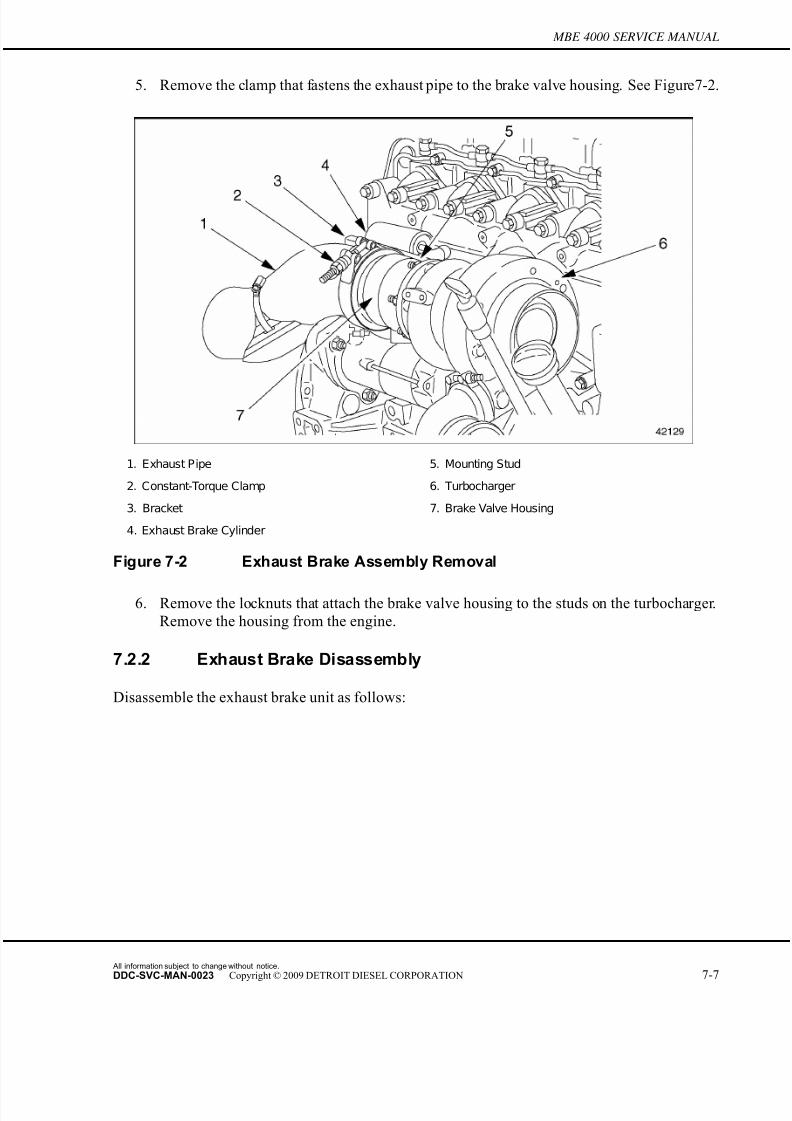
7/22/2019 Manual Mbe 4000 Taller
http://slidepdf.com/reader/full/manual-mbe-4000-taller 431/630
MBE 4000 SERVICE MANUAL
5. Remove the clamp that fastens the exhaust pipe to the brake valve housing. See Figure 7-2.
1. Exhaust Pipe 5. Mounting Stud
2. Constant-Torque Clamp 6. Turbocharger
3. Bracket 7. Brake Valve Housing
4. Exhaust Brake Cylinder
Figure 7-2 Exhaust Brake Assembly Removal
6. Remove the locknuts that attach the brake valve housing to the studs on the turbocharger.
Remove the housing from the engine.
7.2.2 Exhaust Brake Disassembly
Disassemble the exhaust brake unit as follows:
All information subject to change without notice.
DDC-SVC-MAN-0023 Copyright © 2009 DETROIT DIESEL CORPORATION 7-7

7/22/2019 Manual Mbe 4000 Taller
http://slidepdf.com/reader/full/manual-mbe-4000-taller 432/630
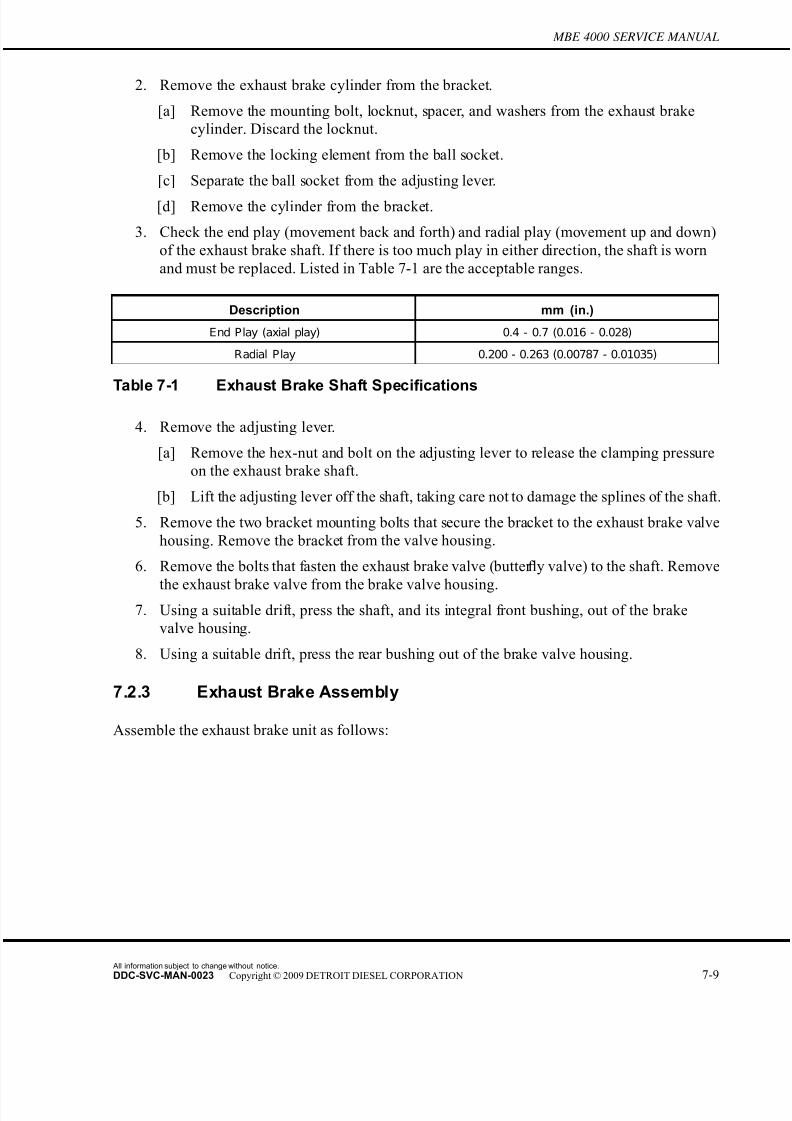
7/22/2019 Manual Mbe 4000 Taller
http://slidepdf.com/reader/full/manual-mbe-4000-taller 433/630
MBE 4000 SERVICE MANUAL
2. Remove the exhaust brake cylinder from the bracket.
[a] Remove the mounting bolt, locknut, spacer, and washers from the exhaust brake
cylinder. Discard the locknut.
[b] Remove the locking element from the ball socket.
[c] Separate the ball socket from the adjusting lever.
[d] Remove the cylinder from the bracket.
3. Check the end play (movement back and forth) and radial play (movement up and down)
of the exhaust brake shaft. If there is too much play in either direction, the shaft is worn
and must be replaced. Listed in Table 7-1 are the acceptable ranges.
Description mm (in.)
End Play (axial play) 0.4 - 0.7 (0.016 - 0.028)
Radial Play 0.200 - 0.263 (0.00787 - 0.01035)
Table 7-1 Exhaust Brake Shaft Specifi
cations
4. Remove the adjusting lever.
[a] Remove the hex-nut and bolt on the adjusting lever to release the clamping pressure
on the exhaust brake shaft.
[b] Lift the adjusting lever off the shaft, taking care not to damage the splines of the shaft.
5. Remove the two bracket mounting bolts that secure the bracket to the exhaust brake valve
housing. Remove the bracket from the valve housing.
6. Remove the bolts that fasten the exhaust brake valve (butter fly valve) to the shaft. Remove
the exhaust brake valve from the brake valve housing.7. Using a suitable drift, press the shaft, and its integral front bushing, out of the brake
valve housing.
8. Using a suitable drift, press the rear bushing out of the brake valve housing.
7.2.3 Exhaust Brake Assembly
Assemble the exhaust brake unit as follows:
All information subject to change without notice.
DDC-SVC-MAN-0023 Copyright © 2009 DETROIT DIESEL CORPORATION 7-9
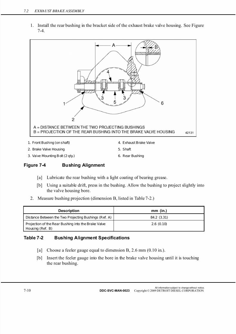
7/22/2019 Manual Mbe 4000 Taller
http://slidepdf.com/reader/full/manual-mbe-4000-taller 434/630
7.2 EXHAUST BRAKE ASSEMBLY
1. Install the rear bushing in the bracket side of the exhaust brake valve housing. See Figure
7-4.
1. Front Bushing (on shaft) 4. Exhaust Brake Valve
2. Brake Valve Housing 5. Shaft
3. Valve Mounting B olt (2 qty.) 6. Rear Bushing
Figure 7-4 Bushing Alignment
[a] Lubricate the rear bushing with a light coating of bearing grease.
[b] Using a suitable drift, press in the bushing. Allow the bushing to project slightly into
the valve housing bore.
2. Measure bushing projection (dimension B, listed in Table 7-2.)
Description mm (in.)
Distance Between the Two Projecting Bushings (Ref. A) 84.2 (3.31)
Projection of the Rear Bushing into the Brake Valve
Housing (Ref. B)
2.6 (0.10)
Table 7-2 Bushing Alignment Specifications
[a] Choose a feeler gauge equal to dimension B, 2.6 mm (0.10 in.).
[b] Insert the feeler gauge into the bore in the brake valve housing until it is touching
the rear bushing.
All information subject to change without notice.
7-10 DDC-SVC-MAN-0023 Copyright © 2009 DETROIT DIESEL CORPORATION

7/22/2019 Manual Mbe 4000 Taller
http://slidepdf.com/reader/full/manual-mbe-4000-taller 435/630
MBE 4000 SERVICE MANUAL
[c] Adjust the projection inward or outward until the face of the bushing is flush with the
feeler gauge.
3. Install the shaft, with its integral front bushing, into the brake valve housing (with the rear
bushing installed).
[a] Lubricate the front bushing with a light coating of bearing grease.
[b] Using a suitable drift, press in the shaft until the front bushing projects slightly intothe other side of the brake valve housing bore.
4. Measure the distance between the bushing faces inside the brake valve housing (dimension
A, see Figure 7-4.)
[a] Using calipers or another suitable measuring device, measure the distance between
the face of the front bushing and the face of the rear bushing.
[b] Adjust the distance until it is equal to 84.2 mm (3.31 in.).
5. Install the exhaust brake valve on the shaft.
[a] Position the valve correctly on the shaft. The valve should be centered inside the
valve housing, and equidistant between the two bushings.
[b] Apply anti-seize compound to the threads of the two valve mounting bolts.
[c] Install and tighten the two valve mounting bolts 30 N·m (22 lb·ft).
[d] With the bolts tightened, move the valve to and fro a few times to make sure it does
not interfere with the brake valve housing at any point.
6. Install the bracket on the brake valve housing. Tighten the bracket mounting bolts 35
N·m (25 lb·ft).
7. Install the adjusting lever on the shaft.
[a] Rotate the valve until it is fully open.
[b] Install the adjusting lever so that the lever stop rests against the bracket with the
valve still fully open.
[c] Install the adjusting-lever bolt and nut. Tighten the nut 15 N·m (11 lb·ft).
8. Install the exhaust brake cylinder on the bracket.
[a] Install the bolt, washers, spacer, and a new locknut on the cylinder and bracket, as
removed.
All information subject to change without notice.
DDC-SVC-MAN-0023 Copyright © 2009 DETROIT DIESEL CORPORATION 7-11
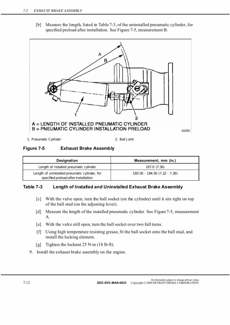
7/22/2019 Manual Mbe 4000 Taller
http://slidepdf.com/reader/full/manual-mbe-4000-taller 436/630
7.2 EXHAUST BRAKE ASSEMBLY
[b] Measure the length, listed in Table 7-3, of the uninstalled pneumatic cylinder, for
specified preload after installation. See Figure 7-5, measurement B.
1. Pneumatic Cylinder 2. Ball J oint
Figure 7-5 Exhaust Brake Assembly
Designation Measurement, mm (in.)
Length of installed pneumatic cylinder 187.0 (7.36)
Length of uninstalled pneumatic cylinder, for
specified preload after installation
183.50 - 184.50 (7.22 - 7.26)
Table 7-3 Length of Installed and Uninstalled Exhaust Brake Assembly
[c] With the valve open, turn the ball socket (on the cylinder) until it sits right on top
of the ball stud (on the adjusting lever).
[d] Measure the length of the installed pneumatic cylinder. See Figure 7-5, measurement
A.
[e] With the valve still open, turn the ball socket over two full turns.
[f] Using high temperature resisting grease, fit the ball socket onto the ball stud, and
install the locking element.
[g] Tighten the locknut 25 N·m (18 lb·ft).
9. Install the exhaust brake assembly on the engine.
All information subject to change without notice.
7-12 DDC-SVC-MAN-0023 Copyright © 2009 DETROIT DIESEL CORPORATION

7/22/2019 Manual Mbe 4000 Taller
http://slidepdf.com/reader/full/manual-mbe-4000-taller 437/630
MBE 4000 SERVICE MANUAL
7.2.4 Exhaust Brake Assembly Installation
Install the exhaust brake assembly as follows:
1. Clean the mating surfaces on the brake valve housing and the turbocharger.
2. Install the brake valve housing on the turbocharger by slipping the housing over the
turbocharger studs. Tighten the locknuts 50 N·m (37 lb·ft).
PERSONAL INJURY
To avoid injury from the sudden release of a high-pressurehose connection, wear a face shield or goggles.
3. Install the compressed-air line on the exhaust brake cylinder.
4. Clean the sealing surfaces on the exhaust pipe and brake valve housing.
5. Slide the exhaust pipe and clamp over the end of the housing. Tighten the clamp.
6. Install the air cleaner.
7. Connect the batteries, lower the hood, and remove the chocks from the rear tires.
All information subject to change without notice.
DDC-SVC-MAN-0023 Copyright © 2009 DETROIT DIESEL CORPORATION 7-13
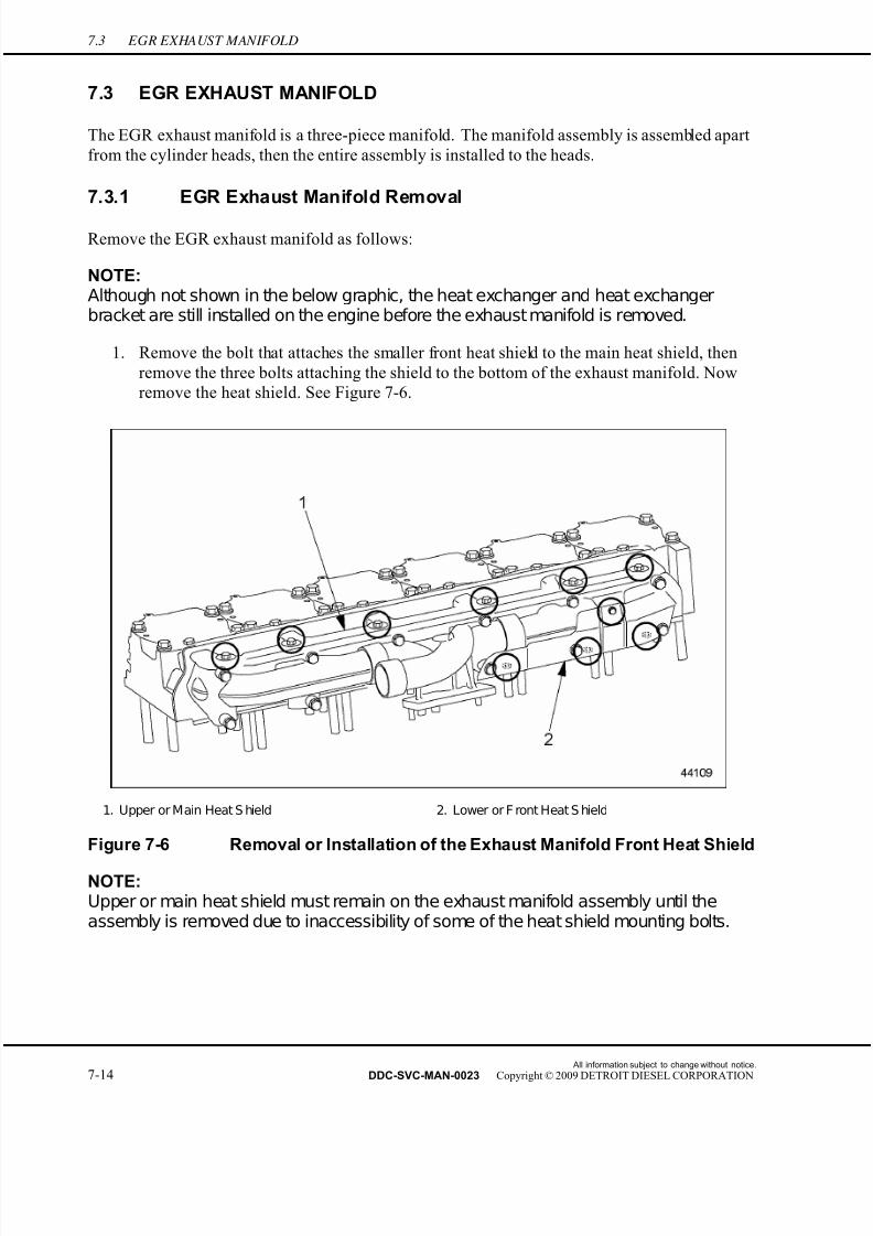
7/22/2019 Manual Mbe 4000 Taller
http://slidepdf.com/reader/full/manual-mbe-4000-taller 438/630
7.3 EGR EXHAUST MANIFOLD
7.3 EGR EXHAUST MANIFOLD
The EGR exhaust manifold is a three-piece manifold. The manifold assembly is assembled apart
from the cylinder heads, then the entire assembly is installed to the heads.
7.3.1 EGR Exhaust Manifold Removal
Remove the EGR exhaust manifold as follows:
NOTE:Although not shown in the below graphic, the heat exchanger and heat exchangerbracket are still installed on the engine before the exhaust manifold is removed.
1. Remove the bolt that attaches the smaller front heat shield to the main heat shield, then
remove the three bolts attaching the shield to the bottom of the exhaust manifold. Now
remove the heat shield. See Figure 7-6.
1. Upper or Main Heat S hield 2. Lower or F ront Heat S hield
Figure 7-6 Removal or Installation of the Exhaust Manifold Front Heat Shield
NOTE:Upper or main heat shield must remain on the exhaust manifold assembly until theassembly is removed due to inaccessibility of some of the heat shield mounting bolts.
All information subject to change without notice.
7-14 DDC-SVC-MAN-0023 Copyright © 2009 DETROIT DIESEL CORPORATION
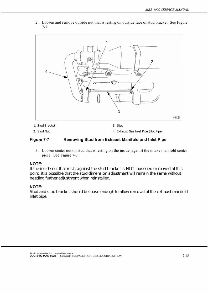
7/22/2019 Manual Mbe 4000 Taller
http://slidepdf.com/reader/full/manual-mbe-4000-taller 439/630
MBE 4000 SERVICE MANUAL
2. Loosen and remove outside nut that is resting on outside face of stud bracket. See Figure
7-7.
1. Stud Bracket 3. Stud
2. Stud Nut 4. Exhaust Gas Inlet Pipe (Hot Pipe)
Figure 7-7 Removing Stud from Exhaust Manifold and Inlet Pipe
3. Loosen center nut on stud that is resting on the inside, against the intake manifold center
piece. See Figure 7-7.
NOTE:If the inside nut that rests against the stud bracket is NOT loosened or moved at thispoint, it is possible that the stud dimension adjustment will remain the same withoutneeding further adjustment when reinstalled.
NOTE:Stud and stud bracket should be loose enough to allow removal of the exhaust manifoldinlet pipe.
All information subject to change without notice.
DDC-SVC-MAN-0023 Copyright © 2009 DETROIT DIESEL CORPORATION 7-15

7/22/2019 Manual Mbe 4000 Taller
http://slidepdf.com/reader/full/manual-mbe-4000-taller 440/630
7.3 EGR EXHAUST MANIFOLD
4. Loosen and remove bolt from positioning clamp which holds the gas inlet pipe to the
throttle valve. See Figure 7-8.
Figure 7-8 Removing or Installing Positioning Clamp to Throttle Inlet Pipe
All information subject to change without notice.
7-16 DDC-SVC-MAN-0023 Copyright © 2009 DETROIT DIESEL CORPORATION

7/22/2019 Manual Mbe 4000 Taller
http://slidepdf.com/reader/full/manual-mbe-4000-taller 441/630
MBE 4000 SERVICE MANUAL
5. Gently pull exhaust manifold gas inlet pipe from center piece of exhaust manifold and
from throttle valve (see arrows in graphic). Remove the fey rings (four per groove) on the
gas inlet pipe leading to the exhaust manifold center piece. See Figure 7-9.
Figure 7-9 Exhaust Manifold Gas Inlet Pipe Removal
All information subject to change without notice.
DDC-SVC-MAN-0023 Copyright © 2009 DETROIT DIESEL CORPORATION 7-17
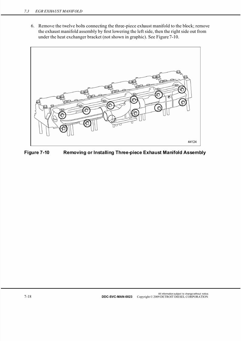
7/22/2019 Manual Mbe 4000 Taller
http://slidepdf.com/reader/full/manual-mbe-4000-taller 442/630
7.3 EGR EXHAUST MANIFOLD
6. Remove the twelve bolts connecting the three-piece exhaust manifold to the block; remove
the exhaust manifold assembly by first lowering the left side, then the right side out from
under the heat exchanger bracket (not shown in graphic). See Figure 7-10.
Figure 7-10 Removing or Installing Three-piece Exhaust Manifold Assembly
All information subject to change without notice.
7-18 DDC-SVC-MAN-0023 Copyright © 2009 DETROIT DIESEL CORPORATION
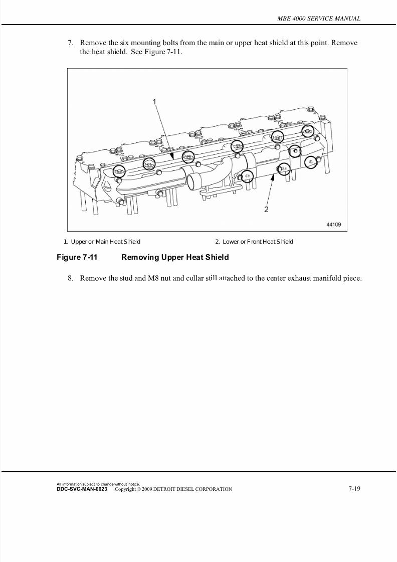
7/22/2019 Manual Mbe 4000 Taller
http://slidepdf.com/reader/full/manual-mbe-4000-taller 443/630
MBE 4000 SERVICE MANUAL
7. Remove the six mounting bolts from the main or upper heat shield at this point. Remove
the heat shield. See Figure 7-11.
1. Upper or Main Heat S hield 2. Lower or F ront Heat S hield
Figure 7-11 Removing Upper Heat Shield
8. Remove the stud and M8 nut and collar still attached to the center exhaust manifold piece.
All information subject to change without notice.
DDC-SVC-MAN-0023 Copyright © 2009 DETROIT DIESEL CORPORATION 7-19
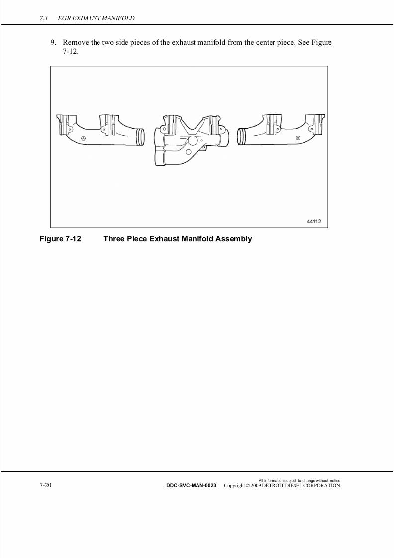
7/22/2019 Manual Mbe 4000 Taller
http://slidepdf.com/reader/full/manual-mbe-4000-taller 444/630
7.3 EGR EXHAUST MANIFOLD
9. Remove the two side pieces of the exhaust manifold from the center piece. See Figure
7-12.
Figure 7-12 Three Piece Exhaust Manifold Assembly
All information subject to change without notice.
7-20 DDC-SVC-MAN-0023 Copyright © 2009 DETROIT DIESEL CORPORATION
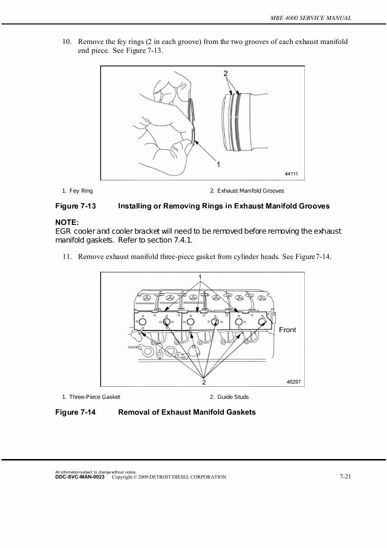
7/22/2019 Manual Mbe 4000 Taller
http://slidepdf.com/reader/full/manual-mbe-4000-taller 445/630
MBE 4000 SERVICE MANUAL
10. Remove the fey rings (2 in each groove) from the two grooves of each exhaust manifold
end piece. See Figure 7-13.
1. Fey Ring 2. Exhaust Manifold Grooves
Figure 7-13 Installing or Removing Rings in Exhaust Manifold Grooves
NOTE:EGR cooler and cooler bracket will need to be removed before removing the exhaustmanifold gaskets. Refer to section 7.4.1.
11. Remove exhaust manifold three-piece gasket from cylinder heads. See Figure 7-14.
1. Three-Piece Gasket 2. Guide Studs
Figure 7-14 Removal of Exhaust Manifold Gaskets
All information subject to change without notice.
DDC-SVC-MAN-0023 Copyright © 2009 DETROIT DIESEL CORPORATION 7-21
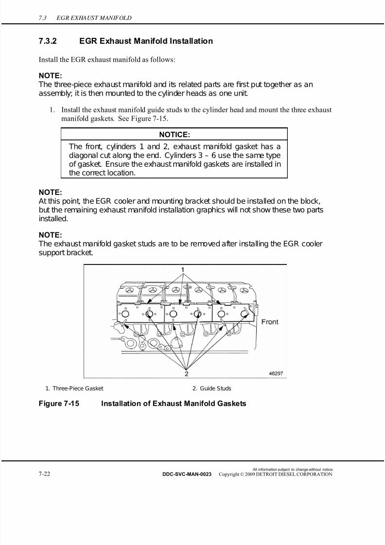
7/22/2019 Manual Mbe 4000 Taller
http://slidepdf.com/reader/full/manual-mbe-4000-taller 446/630
7.3 EGR EXHAUST MANIFOLD
7.3.2 EGR Exhaust Manifold Installation
Install the EGR exhaust manifold as follows:
NOTE: The three-piece exhaust manifold and its related parts are first put together as an
assembly; it is then mounted to the cylinder heads as one unit.
1. Install the exhaust manifold guide studs to the cylinder head and mount the three exhaust
manifold gaskets. See Figure 7-15.
NOTICE:
The front, cylinders 1 and 2, exhaust manifold gasket has adiagonal cut along the end. Cylinders 3 – 6 use the same typeof gasket. Ensure the exhaust manifold gaskets are installed inthe correct location.
NOTE:At this point, the EGR cooler and mounting bracket should be installed on the block,but the remaining exhaust manifold installation graphics will not show these two partsinstalled.
NOTE: The exhaust manifold gasket studs are to be removed after installing the EGR coolersupport bracket.
1. Three-Piece Gasket 2. Guide Studs
Figure 7-15 Installation of Exhaust Manifold Gaskets
All information subject to change without notice.
7-22 DDC-SVC-MAN-0023 Copyright © 2009 DETROIT DIESEL CORPORATION
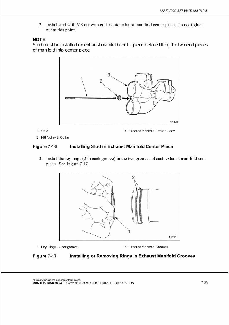
7/22/2019 Manual Mbe 4000 Taller
http://slidepdf.com/reader/full/manual-mbe-4000-taller 447/630
MBE 4000 SERVICE MANUAL
2. Install stud with M8 nut with collar onto exhaust manifold center piece. Do not tighten
nut at this point.
NOTE:Stud must be installed on exhaust manifold center piece beforefitting the two end piecesof manifold into center piece.
1. Stud 3. Exhaust Manifold Center Piece
2. M8 Nut with Collar
Figure 7-16 Installing Stud in Exhaust Manifold Center Piece
3. Install the fey rings (2 in each groove) in the two grooves of each exhaust manifold end
piece. See Figure 7-17.
1. Fey Rings (2 per groove) 2. Exhaust Manifold Grooves
Figure 7-17 Installing or Removing Rings in Exhaust Manifold Grooves
All information subject to change without notice.
DDC-SVC-MAN-0023 Copyright © 2009 DETROIT DIESEL CORPORATION 7-23
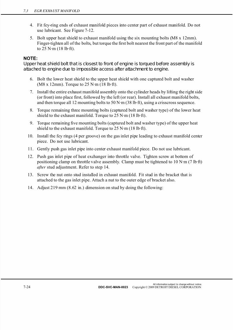
7/22/2019 Manual Mbe 4000 Taller
http://slidepdf.com/reader/full/manual-mbe-4000-taller 448/630
7.3 EGR EXHAUST MANIFOLD
4. Fit fey-ring ends of exhaust manifold pieces into center part of exhaust manifold. Do not
use lubricant. See Figure 7-12.
5. Bolt upper heat shield to exhaust manifold using the six mounting bolts (M8 x 12mm).
Finger-tighten all of the bolts, but torque the first bolt nearest the front part of the manifold
to 25 N·m (18 lb·ft).
NOTE:Upper heat shield bolt that is closest to front of engine is torqued before assembly isattached to engine due to impossible access after attachment to engine.
6. Bolt the lower heat shield to the upper heat shield with one captured bolt and washer
(M8 x 12mm). Torque to 25 N·m (18 lb·ft).
7. Install the entire exhaust manifold assembly onto the cylinder heads by lifting the right side
(or front) into place first, followed by the left (or rear). Install all exhaust manifold bolts,
and then torque all 12 mounting bolts to 50 N·m (38 lb·ft), using a crisscross sequence.
8. Torque remaining three mounting bolts (captured bolt and washer type) of the lower heat
shield to the exhaust manifold. Torque to 25 N·m (18 lb·ft).
9. Torque remaining five mounting bolts (captured bolt and washer type) of the upper heat
shield to the exhaust manifold. Torque to 25 N·m (18 lb·ft).
10. Install the fey rings (4 per groove) on the gas inlet pipe leading to exhaust manifold center
piece. Do not use lubricant.
11. Gently push gas inlet pipe into center exhaust manifold piece. Do not use lubricant.
12. Push gas inlet pipe of heat exchanger into throttle valve. Tighten screw at bottom of
positioning clamp on throttle valve assembly. Clamp must be tightened to 10 N·m (7 lb·ft)
after stud adjustment. Refer to step 14.
13. Screw the nut onto stud installed in exhaust manifold. Fit stud in the bracket that isattached to the gas inlet pipe. Attach a nut to the outer edge of bracket also.
14. Adjust 219 mm (8.62 in.) dimension on stud by doing the following:
All information subject to change without notice.
7-24 DDC-SVC-MAN-0023 Copyright © 2009 DETROIT DIESEL CORPORATION

7/22/2019 Manual Mbe 4000 Taller
http://slidepdf.com/reader/full/manual-mbe-4000-taller 449/630
MBE 4000 SERVICE MANUAL
[a] Apply 25 N·m (18 lb·ft) tightening torque to the nut on exhaust manifold. Position
stud to avoid any friction between the exhaust manifold and the gas inlet pipe. See
Step One in Figure 7-18.
Figure 7-18 Stud Adjustment
[b] Adjust dimension to 219 mm (8.62 in.). This measurement is from the machined face
of manifold to the resting face on the pipe. See Step Two in Figure 7-18.
[c] Bring nut against the resting face on pipe (internal). See Step Three in Figure 7-18.[d] Apply 25 N·m (18 lb·ft) tightening torque to nut on resting face on pipe (external).
See Step Four in Figure 7-18.
[e] Apply 25 N·m (18 lb·ft) tightening torque to nut on resting face on pipe (internal).
See Step Five in Figure 7-18.
All information subject to change without notice.
DDC-SVC-MAN-0023 Copyright © 2009 DETROIT DIESEL CORPORATION 7-25
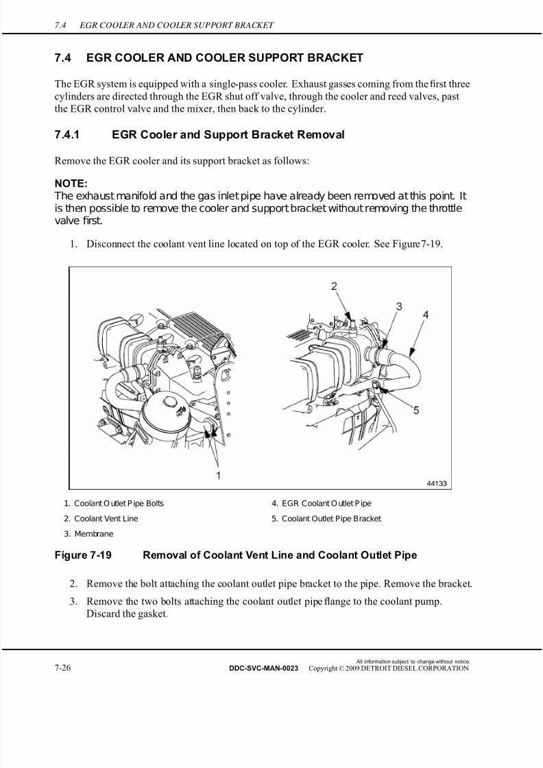
7/22/2019 Manual Mbe 4000 Taller
http://slidepdf.com/reader/full/manual-mbe-4000-taller 450/630
7.4 EGR COOLER AND COOLER SUPPORT BRACKET
7.4 EGR COOLER AND COOLER SUPPORT BRACKET
The EGR system is equipped with a single-pass cooler. Exhaust gasses coming from the first three
cylinders are directed through the EGR shut off valve, through the cooler and reed valves, past
the EGR control valve and the mixer, then back to the cylinder.
7.4.1 EGR Cooler and Support Bracket Removal
Remove the EGR cooler and its support bracket as follows:
NOTE: The exhaust manifold and the gas inlet pipe have already been removed at this point. Itis then possible to remove the cooler and support bracket without removing the throttlevalve first.
1. Disconnect the coolant vent line located on top of the EGR cooler. See Figure 7-19.
1. Coolant O utlet P ipe Bolts 4. EGR Coolant O utlet P ipe
2. Coolant Vent Line 5. Coolant Outlet Pipe Bracket
3. Membrane
Figure 7-19 Removal of Coolant Vent Line and Coolant Outlet Pipe
2. Remove the bolt attaching the coolant outlet pipe bracket to the pipe. Remove the bracket.
3. Remove the two bolts attaching the coolant outlet pipe flange to the coolant pump.
Discard the gasket.
All information subject to change without notice.
7-26 DDC-SVC-MAN-0023 Copyright © 2009 DETROIT DIESEL CORPORATION

7/22/2019 Manual Mbe 4000 Taller
http://slidepdf.com/reader/full/manual-mbe-4000-taller 451/630
MBE 4000 SERVICE MANUAL
4. Pull the coolant outlet pipe away from the cooler, leaving the connecting membrane
in the EGR cooler boss.
5. Remove the EGR temperature sensor from the reed valve housing and disconnect the
sensor wiring harness where it is attached with cable ties to the reed valve housing
mounting bracket. See Figure 7-20.
1. E GR Air Temperature S ensor 2. R eed Valve Housing Bracket
Figure 7-20 Removing EGR Air Temperature Sensor
6. Remove the three bolts from the front bracket that holds and stabilizes the reed valve
housing to the thermostat housing. See Figure 7-20.
All information subject to change without notice.
DDC-SVC-MAN-0023 Copyright © 2009 DETROIT DIESEL CORPORATION 7-27

7/22/2019 Manual Mbe 4000 Taller
http://slidepdf.com/reader/full/manual-mbe-4000-taller 452/630
7.4 EGR COOLER AND COOLER SUPPORT BRACKET
7. Remove the two front sheet metal support-to-cooler support bolts (See number 1 in
graphic). See Figure 7-21.
1. Front Sheet Metal Support-to-Cooler SupportBolts 3. EGR Cooler-to-Sheet Metal Support Bolts
2. Front Sheet Metal Support
Figure 7-21 Removing Front Sheet Metal Support
NOTE:
Do not remove the eight mounting bolts attaching the reed valve housing to the coolerat this time. Also, do not remove the two EGR cooler-to-sheet metal support bolts atthis time. They will all be removed once the EGR cooler as an assembly is taken off of the engine.
All information subject to change without notice.
7-28 DDC-SVC-MAN-0023 Copyright © 2009 DETROIT DIESEL CORPORATION

7/22/2019 Manual Mbe 4000 Taller
http://slidepdf.com/reader/full/manual-mbe-4000-taller 453/630
MBE 4000 SERVICE MANUAL
8. Remove the two bolts mounting the lower coolant inlet pipe to the block and remove the
bracket bolt, just below the membrane, which attaches the lower coolant inlet pipe to the
block. Remove gasket. See Figure 7-22.
1. Lower C oolant I nlet P ipe 4. S hut off Valve Housing Bolt (2 qty.)
2. Membrane 5. Air Supply Line
3. Air Line Mounting Bolts
Figure 7-22 Removing Coolant Inlet Pipe
9. Pull down on the lower coolant inlet pipe to loosen it from the upper pipe. Remove the
membrane also.
NOTE:Have a container nearby to drain any unused coolant from the inlet pipes.
10. Remove the two shut off valve housing bolts that hold the valve housing to the EGR cooler
support. See Figure 7-22.
11. Remove the air line mounting bolts. Loosen and remove the air supply line from the
EGR shut off valve. See Figure 7-22.
All information subject to change without notice.
DDC-SVC-MAN-0023 Copyright © 2009 DETROIT DIESEL CORPORATION 7-29
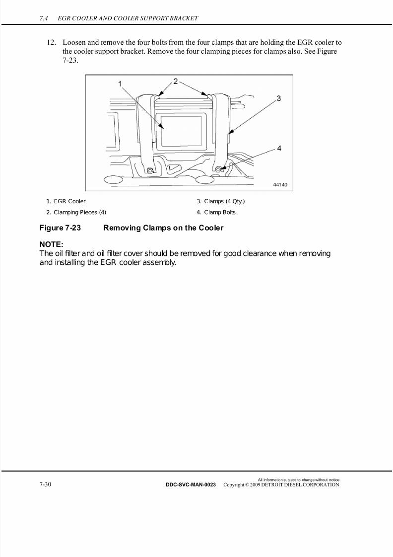
7/22/2019 Manual Mbe 4000 Taller
http://slidepdf.com/reader/full/manual-mbe-4000-taller 454/630
7.4 EGR COOLER AND COOLER SUPPORT BRACKET
12. Loosen and remove the four bolts from the four clamps that are holding the EGR cooler to
the cooler support bracket. Remove the four clamping pieces for clamps also. See Fi gure
7-23.
1. EGR Cooler 3. Clamps (4 Qty.)
2. Clamping Pieces (4) 4. Clamp Bolts
Figure 7-23 Removing Clamps on the Cooler
NOTE: The oil filter and oil filter cover should be removed for good clearance when removingand installing the EGR cooler assembly.
All information subject to change without notice.
7-30 DDC-SVC-MAN-0023 Copyright © 2009 DETROIT DIESEL CORPORATION

7/22/2019 Manual Mbe 4000 Taller
http://slidepdf.com/reader/full/manual-mbe-4000-taller 455/630
MBE 4000 SERVICE MANUAL
13. With the cooler completely loosened at this point, pull the cooler housing flange away
from the EGR control valve. As the cooler is lifted, slide the cooler inlet pipe up through
the opening in the cooler support bracket. See Figure 7-24.
1. Cylinder Heads 4. EGR Cooler
2. E GR C oolerTightening C lamps 5. E GR C ooler S upport
3. Tightening Tool for Clamps
Figure 7-24 Removing EGR Cooler
NOTE:Before removing the eight bolts from the EGR cooler support, insert the four guide studsinto the exhaust manifold gasket holes to support the gaskets once the cooler support isremoved.
All information subject to change without notice.
DDC-SVC-MAN-0023 Copyright © 2009 DETROIT DIESEL CORPORATION 7-31
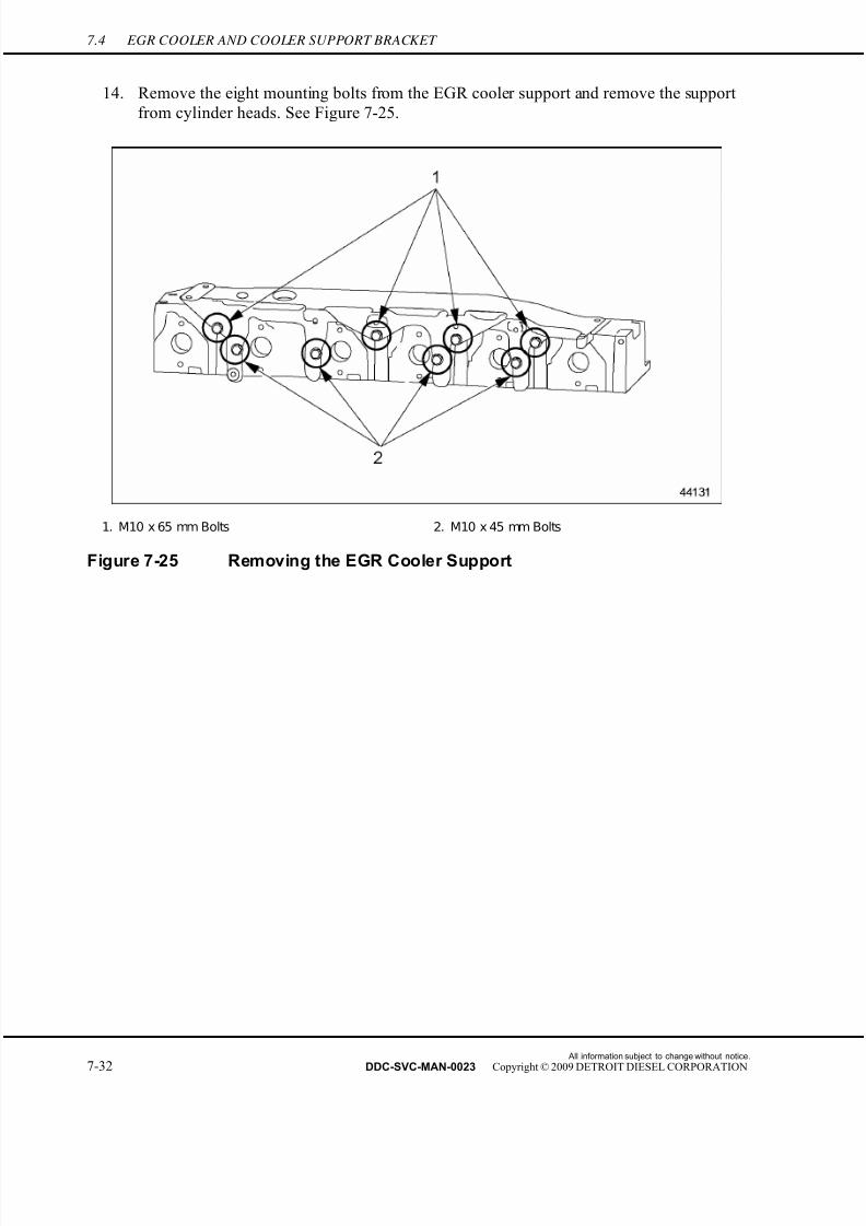
7/22/2019 Manual Mbe 4000 Taller
http://slidepdf.com/reader/full/manual-mbe-4000-taller 456/630
7.4 EGR COOLER AND COOLER SUPPORT BRACKET
14. Remove the eight mounting bolts from the EGR cooler support and remove the support
from cylinder heads. See Figure 7-25.
1. M10 x 65 mm Bolts 2. M10 x 45 mm Bolts
Figure 7-25 Removing the EGR Cooler Support
All information subject to change without notice.
7-32 DDC-SVC-MAN-0023 Copyright © 2009 DETROIT DIESEL CORPORATION
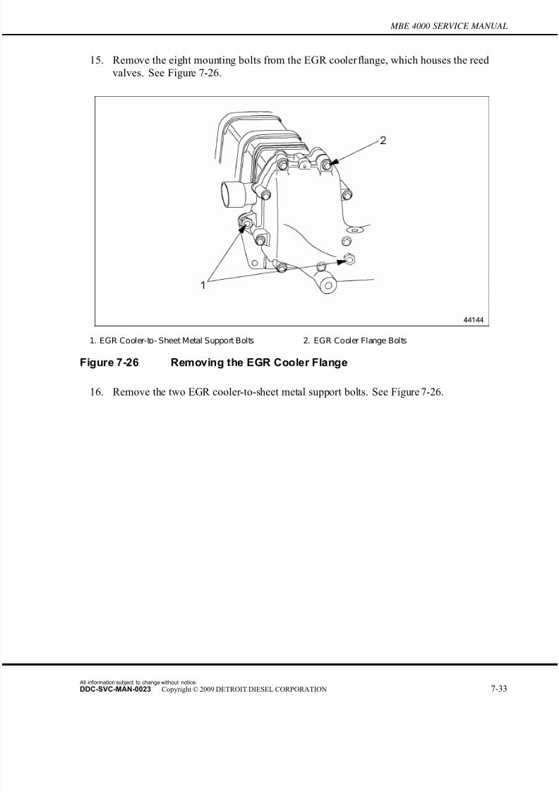
7/22/2019 Manual Mbe 4000 Taller
http://slidepdf.com/reader/full/manual-mbe-4000-taller 457/630
MBE 4000 SERVICE MANUAL
15. Remove the eight mounting bolts from the EGR cooler flange, which houses the reed
valves. See Figure 7-26.
1. EGR Cooler-to- Sheet Metal Support Bolts 2. EGR Cooler Flange Bolts
Figure 7-26 Removing the EGR Cooler Flange
16. Remove the two EGR cooler-to-sheet metal support bolts. See Figure 7-26.
All information subject to change without notice.
DDC-SVC-MAN-0023 Copyright © 2009 DETROIT DIESEL CORPORATION 7-33

7/22/2019 Manual Mbe 4000 Taller
http://slidepdf.com/reader/full/manual-mbe-4000-taller 458/630
7.4 EGR COOLER AND COOLER SUPPORT BRACKET
17. Remove the reed valves from housing. See Figure 7-27.
1. EGR Cooler Housing 4. EGR Reed Valve Flange
2. EGR Cooler Gasket 5. Reed Valves
3. EGR Cooler Intermediate Flange
Figure 7-27 Removing the EGR Cooler Flange and Components
18. Remove the intermediate flange and gasket from cooler flange assembly. See Figure 7-27.
7.4.2 EGR Cooler and Support Bracket Installation
Install the EGR cooler and the EGR cooler support bracket as follows:
NOTE:Exhaust manifold gaskets will have to be installed before EGR cooler support or coolercan be installed. Refer to section 7.3.2.
All information subject to change without notice.
7-34 DDC-SVC-MAN-0023 Copyright © 2009 DETROIT DIESEL CORPORATION

7/22/2019 Manual Mbe 4000 Taller
http://slidepdf.com/reader/full/manual-mbe-4000-taller 459/630
MBE 4000 SERVICE MANUAL
1. Install coolant outlet pipe. Install the two M8 x 25 mm bolts through the coolant pipe
flange, metal gasket and into the coolant pump. Leave loose until the cooler assembly is
installed, then torque bolts to 35 N·m (26 lb·ft). See Figure 7-28.
1. Coolant Outlet P ipe Bolts 4. EGR Coolant Outlet P ipe
2. Coolant Vent Line 5. Coolant Outlet Pipe Bracket
3. Membrane
Figure 7-28 Installation of Coolant Outlet Pipe
NOTE:Coolant outlet pipe must be installed to coolant pump before the EGR cooler supportand cooler are installed.
All information subject to change without notice.
DDC-SVC-MAN-0023 Copyright © 2009 DETROIT DIESEL CORPORATION 7-35
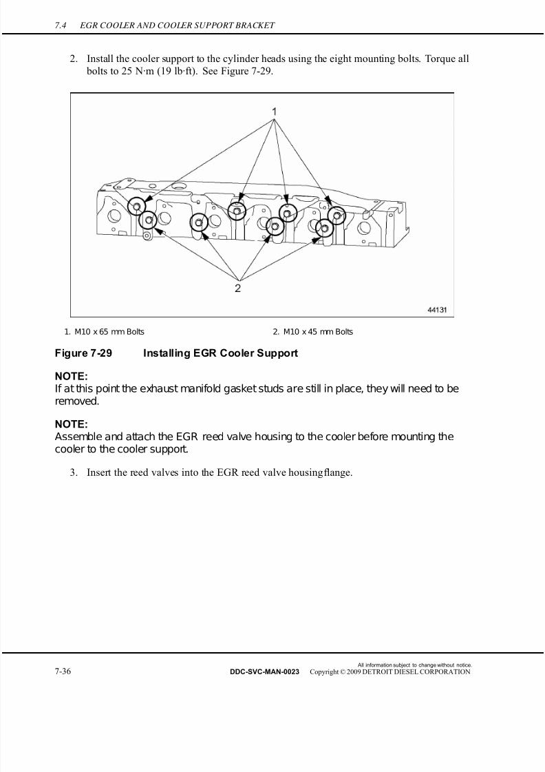
7/22/2019 Manual Mbe 4000 Taller
http://slidepdf.com/reader/full/manual-mbe-4000-taller 460/630
7.4 EGR COOLER AND COOLER SUPPORT BRACKET
2. Install the cooler support to the cylinder heads using the eight mounting bolts. Torque all
bolts to 25 N·m (19 lb·ft). See Figure 7-29.
1. M10 x 65 mm Bolts 2. M10 x 45 mm Bolts
Figure 7-29 Installing EGR Cooler Support
NOTE:If at this point the exhaust manifold gasket studs are still in place, they will need to be
removed.
NOTE:Assemble and attach the EGR reed valve housing to the cooler before mounting thecooler to the cooler support.
3. Insert the reed valves into the EGR reed valve housing flange.
All information subject to change without notice.
7-36 DDC-SVC-MAN-0023 Copyright © 2009 DETROIT DIESEL CORPORATION
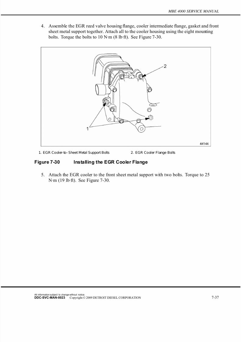
7/22/2019 Manual Mbe 4000 Taller
http://slidepdf.com/reader/full/manual-mbe-4000-taller 461/630
MBE 4000 SERVICE MANUAL
4. Assemble the EGR reed valve housing flange, cooler intermediate flange, gasket and front
sheet metal support together. Attach all to the cooler housing using the eight mounting
bolts. Torque the bolts to 10 N·m (8 lb·ft). See Figure 7-30.
1. EGR Cooler-to- Sheet Metal Support Bolts 2. EGR Cooler Flange Bolts
Figure 7-30 Installing the EGR Cooler Flange
5. Attach the EGR cooler to the front sheet metal support with two bolts. Torque to 25
N·m (19 lb·ft). See Figure 7-30.
All information subject to change without notice.
DDC-SVC-MAN-0023 Copyright © 2009 DETROIT DIESEL CORPORATION 7-37
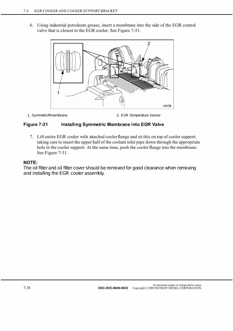
7/22/2019 Manual Mbe 4000 Taller
http://slidepdf.com/reader/full/manual-mbe-4000-taller 462/630
7.4 EGR COOLER AND COOLER SUPPORT BRACKET
6. Using industrial petroleum grease, insert a membrane into the side of the EGR control
valve that is closest to the EGR cooler. See Figure 7-31.
1. SymmetricMmembrane 2. E GR Temperature Sensor
Figure 7-31 Installing Symmetric Membrane into EGR Valve
7. Lift entire EGR cooler with attached cooler flange and sit this on top of cooler support,
taking care to insert the upper half of the coolant inlet pipe down through the appropriate
hole in the cooler support. At the same time, push the cooler flange into the membrane.
See Figure 7-31.
NOTE: The oil filter and oil filter cover should be removed for good clearance when removing
and installing the EGR cooler assembly.
All information subject to change without notice.
7-38 DDC-SVC-MAN-0023 Copyright © 2009 DETROIT DIESEL CORPORATION
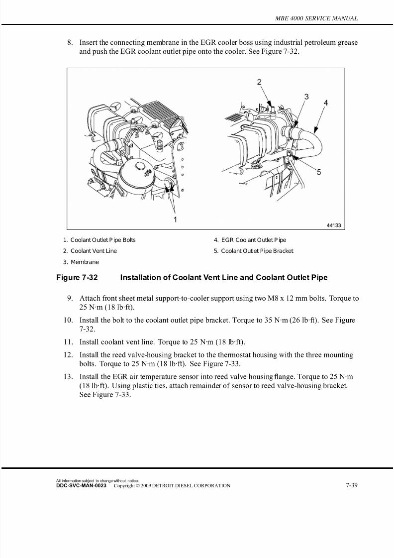
7/22/2019 Manual Mbe 4000 Taller
http://slidepdf.com/reader/full/manual-mbe-4000-taller 463/630
MBE 4000 SERVICE MANUAL
8. Insert the connecting membrane in the EGR cooler boss using industrial petroleum grease
and push the EGR coolant outlet pipe onto the cooler. See Figure 7-32.
1. Coolant Outlet P ipe Bolts 4. EGR Coolant Outlet P ipe
2. Coolant Vent Line 5. Coolant Outlet Pipe Bracket
3. Membrane
Figure 7-32 Installation of Coolant Vent Line and Coolant Outlet Pipe
9. Attach front sheet metal support-to-cooler support using two M8 x 12 mm bolts. Torque to
25 N·m (18 lb·ft).
10. Install the bolt to the coolant outlet pipe bracket. Torque to 35 N·m (26 lb·ft). See Figure
7-32.
11. Install coolant vent line. Torque to 25 N·m (18 lb·ft).
12. Install the reed valve-housing bracket to the thermostat housing with the three mounting
bolts. Torque to 25 N·m (18 lb·ft). See Figure 7-33.
13. Install the EGR air temperature sensor into reed valve housing flange. Torque to 25 N·m
(18 lb·ft). Using plastic ties, attach remainder of sensor to reed valve-housing bracket.
See Figure 7-33.
All information subject to change without notice.
DDC-SVC-MAN-0023 Copyright © 2009 DETROIT DIESEL CORPORATION 7-39
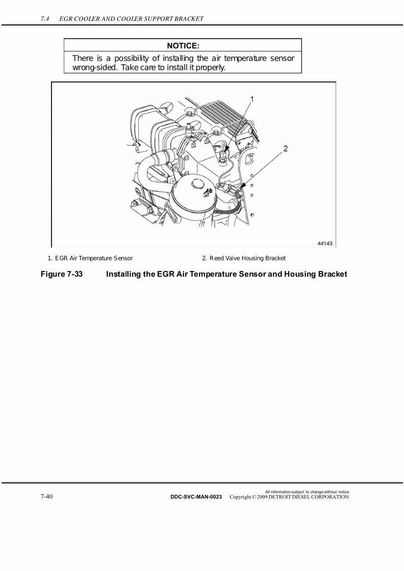
7/22/2019 Manual Mbe 4000 Taller
http://slidepdf.com/reader/full/manual-mbe-4000-taller 464/630
7.4 EGR COOLER AND COOLER SUPPORT BRACKET
NOTICE:
There is a possibility of installing the air temperature sensorwrong-sided. Take care to install it properly.
1. E GR Air Temperature S ensor 2. R eed Valve Housing Bracket
Figure 7-33 Installing the EGR Air Temperature Sensor and Housing Bracket
All information subject to change without notice.
7-40 DDC-SVC-MAN-0023 Copyright © 2009 DETROIT DIESEL CORPORATION
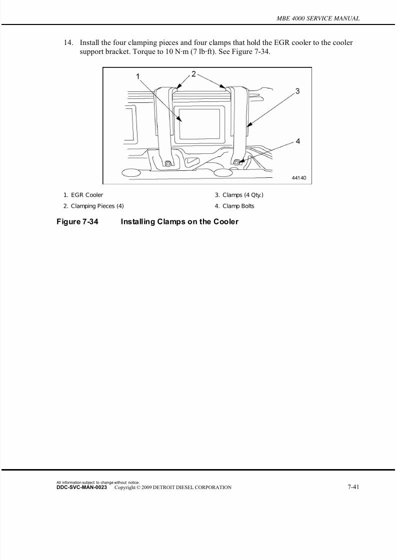
7/22/2019 Manual Mbe 4000 Taller
http://slidepdf.com/reader/full/manual-mbe-4000-taller 465/630
MBE 4000 SERVICE MANUAL
14. Install the four clamping pieces and four clamps that hold the EGR cooler to the cooler
support bracket. Torque to 10 N·m (7 lb·ft). See Figure 7-34.
1. EGR Cooler 3. Clamps (4 Qty.)
2. Clamping Pieces (4) 4. Clamp Bolts
Figure 7-34 Installing Clamps on the Cooler
All information subject to change without notice.
DDC-SVC-MAN-0023 Copyright © 2009 DETROIT DIESEL CORPORATION 7-41
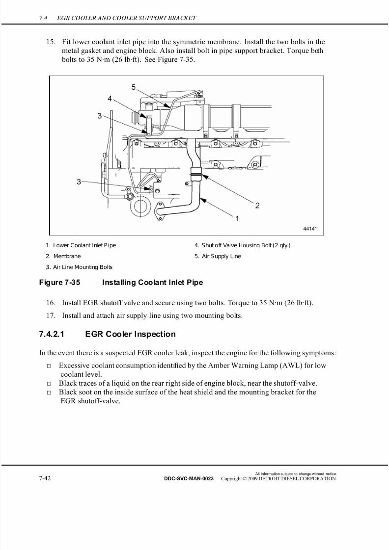
7/22/2019 Manual Mbe 4000 Taller
http://slidepdf.com/reader/full/manual-mbe-4000-taller 466/630
7.4 EGR COOLER AND COOLER SUPPORT BRACKET
15. Fit lower coolant inlet pipe into the symmetric membrane. Install the two bolts in the
metal gasket and engine block. Also install bolt in pipe support bracket. Torque both
bolts to 35 N·m (26 lb·ft). See Figure 7-35.
1. Lower Coolant I nlet P ipe 4. Shut off Valve Housing Bolt (2 qty.)
2. Membrane 5. Air Supply Line
3. Air Line Mounting Bolts
Figure 7-35 Installing Coolant Inlet Pipe
16. Install EGR shutoff valve and secure using two bolts. Torque to 35 N·m (26 lb·ft).
17. Install and attach air supply line using two mounting bolts.
7.4.2.1 EGR Cooler Inspection
In the event there is a suspected EGR cooler leak, inspect the engine for the following symptoms:
□ Excessive coolant consumption identified by the Amber Warning Lamp (AWL) for low
coolant level.
□
Black traces of a liquid on the rear right side of engine block, near the shutoff-valve.□ Black soot on the inside surface of the heat shield and the mounting bracket for the
EGR shutoff-valve.
All information subject to change without notice.
7-42 DDC-SVC-MAN-0023 Copyright © 2009 DETROIT DIESEL CORPORATION
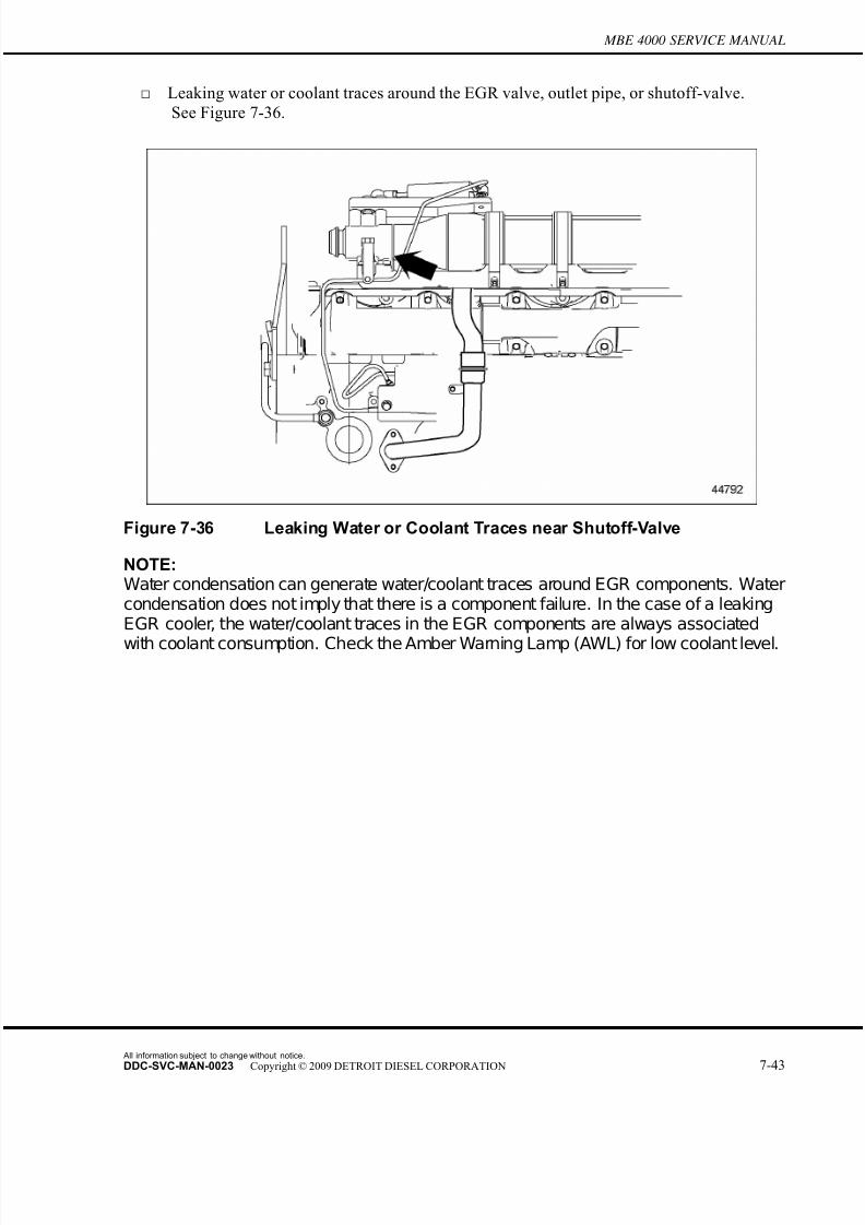
7/22/2019 Manual Mbe 4000 Taller
http://slidepdf.com/reader/full/manual-mbe-4000-taller 467/630
MBE 4000 SERVICE MANUAL
□ Leaking water or coolant traces around the EGR valve, outlet pipe, or shutoff-valve.
See Figure 7-36.
Figure 7-36 Leaking Water or Coolant Traces near Shutoff-Valve
NOTE:Water condensation can generate water/coolant traces around EGR components. Watercondensation does not imply that there is a component failure. In the case of a leakingEGR cooler, the water/coolant traces in the EGR components are always associated
with coolant consumption. Check the Amber Warning Lamp (AWL) for low coolant level.
All information subject to change without notice.
DDC-SVC-MAN-0023 Copyright © 2009 DETROIT DIESEL CORPORATION 7-43
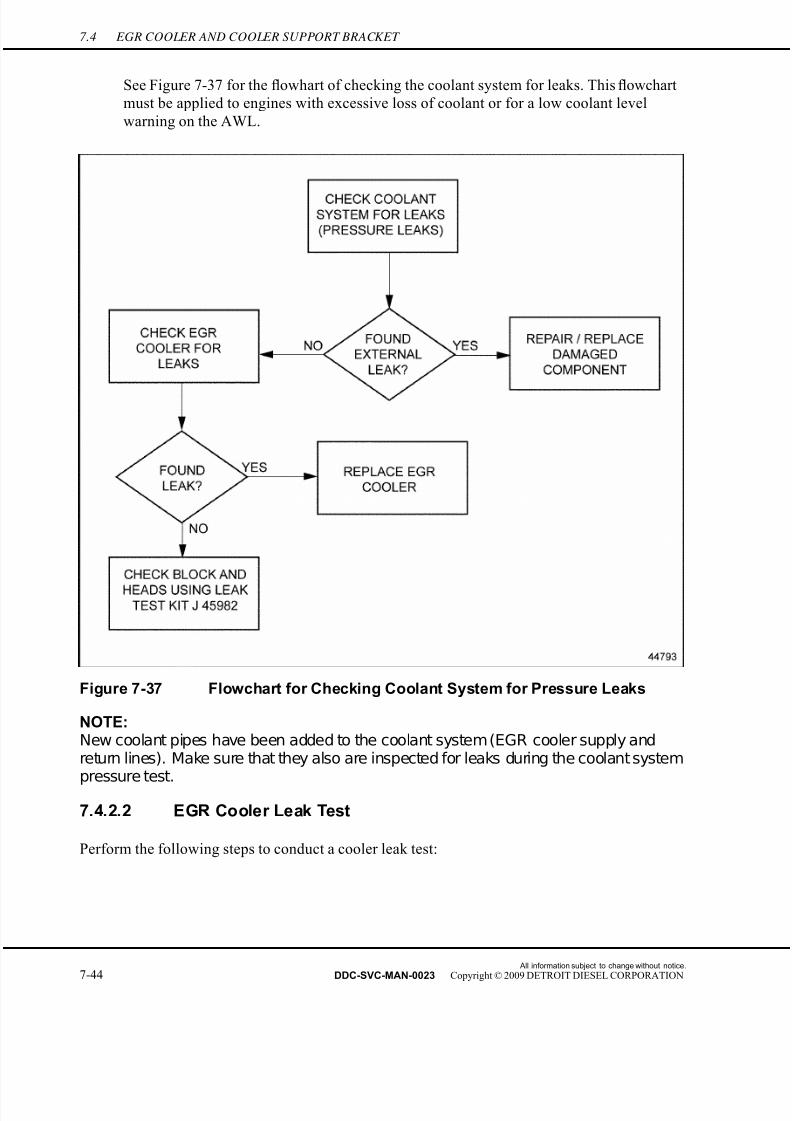
7/22/2019 Manual Mbe 4000 Taller
http://slidepdf.com/reader/full/manual-mbe-4000-taller 468/630
7.4 EGR COOLER AND COOLER SUPPORT BRACKET
See Figure 7-37 for the flowhart of checking the coolant system for leaks. This flowchart
must be applied to engines with excessive loss of coolant or for a low coolant level
warning on the AWL.
Figure 7-37 Flowchart for Checking Coolant System for Pressure Leaks
NOTE:New coolant pipes have been added to the coolant system (EGR cooler supply andreturn lines). Make sure that they also are inspected for leaks during the coolant systempressure test.
7.4.2.2 EGR Cooler Leak Test
Perform the following steps to conduct a cooler leak test:
All information subject to change without notice.
7-44 DDC-SVC-MAN-0023 Copyright © 2009 DETROIT DIESEL CORPORATION

7/22/2019 Manual Mbe 4000 Taller
http://slidepdf.com/reader/full/manual-mbe-4000-taller 469/630
MBE 4000 SERVICE MANUAL
1. Short-circuit or plug the coolant ports on the EGR cooler. See Figure 7-38 for details.
1. EGR Cooler Ports 3. Vent Line
2. EGR Cooler 4. Circuit Hose
Figure 7-38 EGR Cooler Ports Closed
2. Connect an air supply with a pressure regulator and pressure gauge to the EGR cooler
vent line.
EYE INJURY
To avoid injury from flying debris when using compressedair, wear adequate eye protection (face shield or safetygoggles) and do not exceed 276 kPa (40 psi) air pressure.
3. Pressurize the EGR cooler to 90 kPa (13 psi). When adjusting the pressure, do not
exceed 103 kPa (15 psi).
All information subject to change without notice.
DDC-SVC-MAN-0023 Copyright © 2009 DETROIT DIESEL CORPORATION 7-45
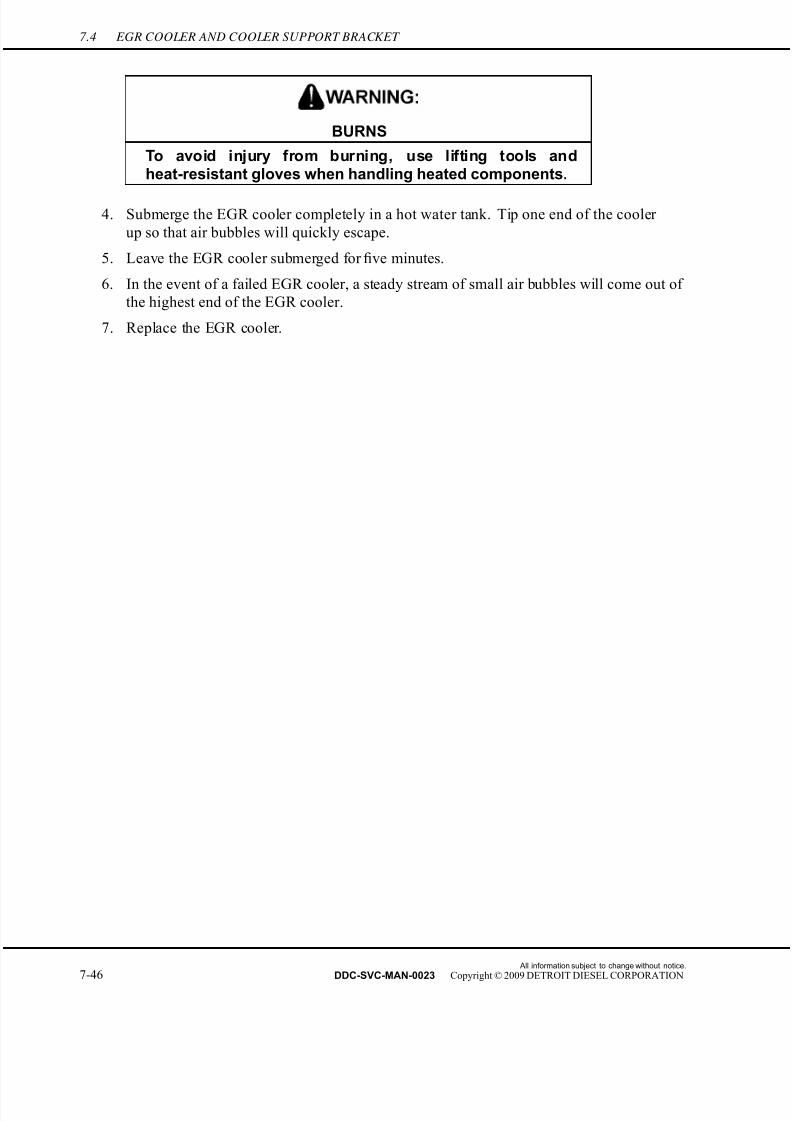
7/22/2019 Manual Mbe 4000 Taller
http://slidepdf.com/reader/full/manual-mbe-4000-taller 470/630
7.4 EGR COOLER AND COOLER SUPPORT BRACKET
BURNS
To avoid injury from burning, use lifting tools andheat-resistant gloves when handling heated components.
4. Submerge the EGR cooler completely in a hot water tank. Tip one end of the cooler
up so that air bubbles will quickly escape.
5. Leave the EGR cooler submerged for five minutes.
6. In the event of a failed EGR cooler, a steady stream of small air bubbles will come out of
the highest end of the EGR cooler.
7. Replace the EGR cooler.
All information subject to change without notice.
7-46 DDC-SVC-MAN-0023 Copyright © 2009 DETROIT DIESEL CORPORATION

7/22/2019 Manual Mbe 4000 Taller
http://slidepdf.com/reader/full/manual-mbe-4000-taller 471/630
MBE 4000 SERVICE MANUAL
7.5 EGR CONTROL VALVE, GAS OUTLET PIPE, AND GAS MIXER
The EGR control valve controls the quantity of exhaust gas returning back to the inta ke manifold.
7.5.1 Removal of EGR Control Valve, Gas Outlet Pipe, and Gas Mixer
Remove the EGR control valve, gas outlet pipe, and gas mixer as follows:
1. Remove the EGR control valve cover mounting bolts attached to the front lifter bracket
and to the rear of the EGR valve. See Figure 7-39.
1. EGR Control Valve Cover Mounting Bolts
Figure 7-39 Removal of EGR Control Valve Cover
2. Loosen the wiring harness terminal from the back cover mounting bracket by punching
the push-mount cable tie out of the drilled hole in the mounting bracket. Remove the two
All information subject to change without notice.
DDC-SVC-MAN-0023 Copyright © 2009 DETROIT DIESEL CORPORATION 7-47
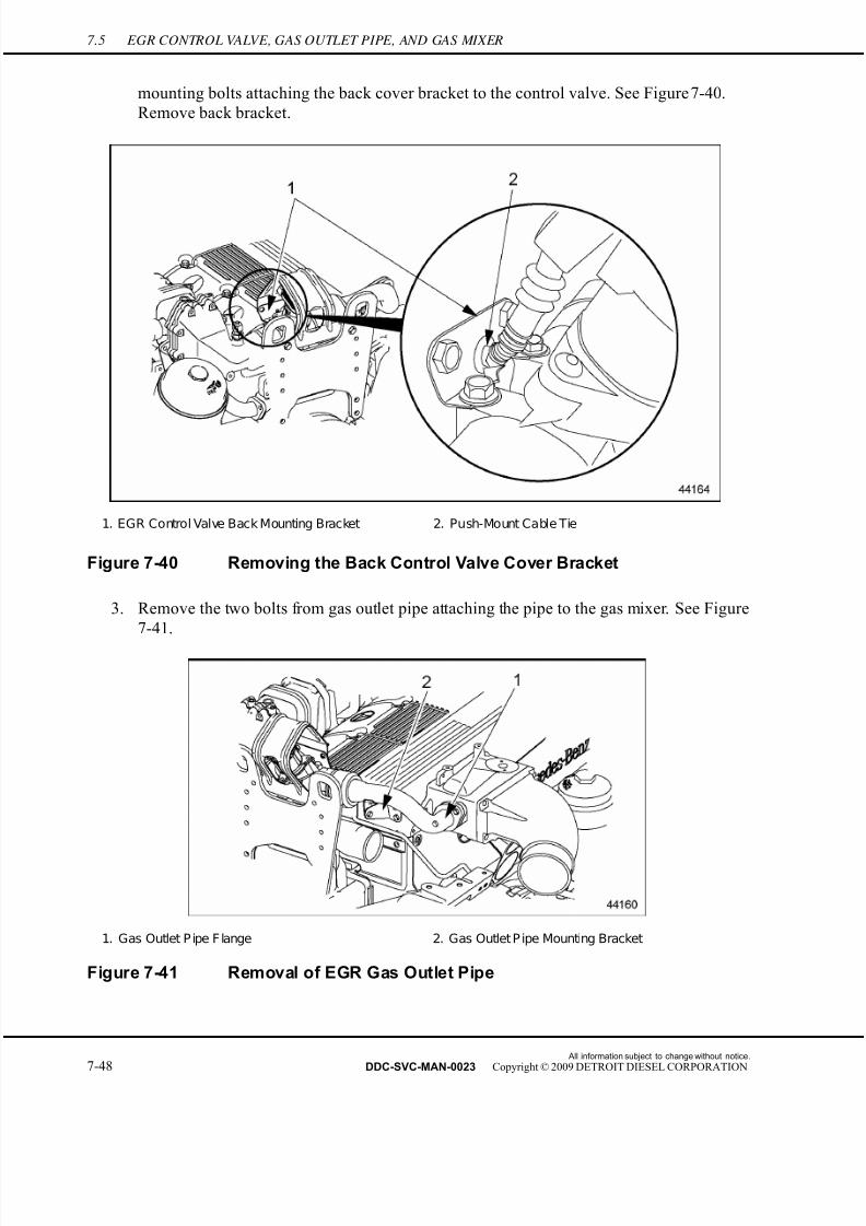
7/22/2019 Manual Mbe 4000 Taller
http://slidepdf.com/reader/full/manual-mbe-4000-taller 472/630
7.5 EGR CONTROL VALVE, GAS OUTLET PIPE, AND GAS MIXER
mounting bolts attaching the back cover bracket to the control valve. See Figure 7-40.
Remove back bracket.
1. EGR Control Valve Back Mounting Bracket 2. Push-Mount Cable Tie
Figure 7-40 Removing the Back Control Valve Cover Bracket
3. Remove the two bolts from gas outlet pipe attaching the pipe to the gas mixer. See Figure
7-41.
1. Gas Outlet P ipe F lange 2. Gas Outlet P ipe Mounting Bracket
Figure 7-41 Removal of EGR Gas Outlet Pipe
All information subject to change without notice.
7-48 DDC-SVC-MAN-0023 Copyright © 2009 DETROIT DIESEL CORPORATION

7/22/2019 Manual Mbe 4000 Taller
http://slidepdf.com/reader/full/manual-mbe-4000-taller 473/630
MBE 4000 SERVICE MANUAL
4. Remove the metal gasket.
5. Remove the three bolts that attach the gas outlet pipe mounting bracket to the intake
manifold and to the outlet pipe. See Figure 7-41.
6. Pull outlet pipe away from mixer and from the EGR control valve, exposing the membrane
in the control valve. See Figure 7-42.
1. Membrane 2. EGR Temperature Sensor
Figure 7-42 Removing the Symmetric Membrane on Gas Outlet Pipe Side
7. Remove membrane from the EGR control valve.
8. Disconnect wiring harness terminal from valve connector. See Figure 7-43.
All information subject to change without notice.
DDC-SVC-MAN-0023 Copyright © 2009 DETROIT DIESEL CORPORATION 7-49
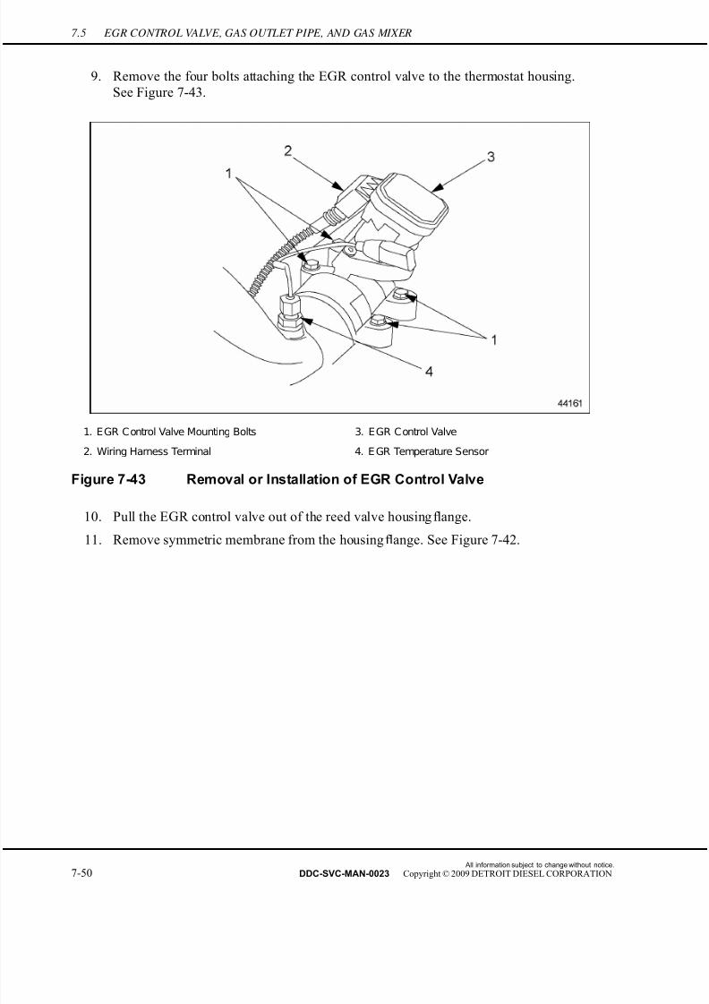
7/22/2019 Manual Mbe 4000 Taller
http://slidepdf.com/reader/full/manual-mbe-4000-taller 474/630
7.5 EGR CONTROL VALVE, GAS OUTLET PIPE, AND GAS MIXER
9. Remove the four bolts attaching the EGR control valve to the thermostat housing.
See Figure 7-43.
1. EGR Control Valve Mounting Bolts 3. EGR Control Valve
2. Wiring Harness Terminal 4. E GR Temperature Sensor
Figure 7-43 Removal or Installation of EGR Control Valve
10. Pull the EGR control valve out of the reed valve housing flange.
11. Remove symmetric membrane from the housing flange. See Figure 7-42.
All information subject to change without notice.
7-50 DDC-SVC-MAN-0023 Copyright © 2009 DETROIT DIESEL CORPORATION
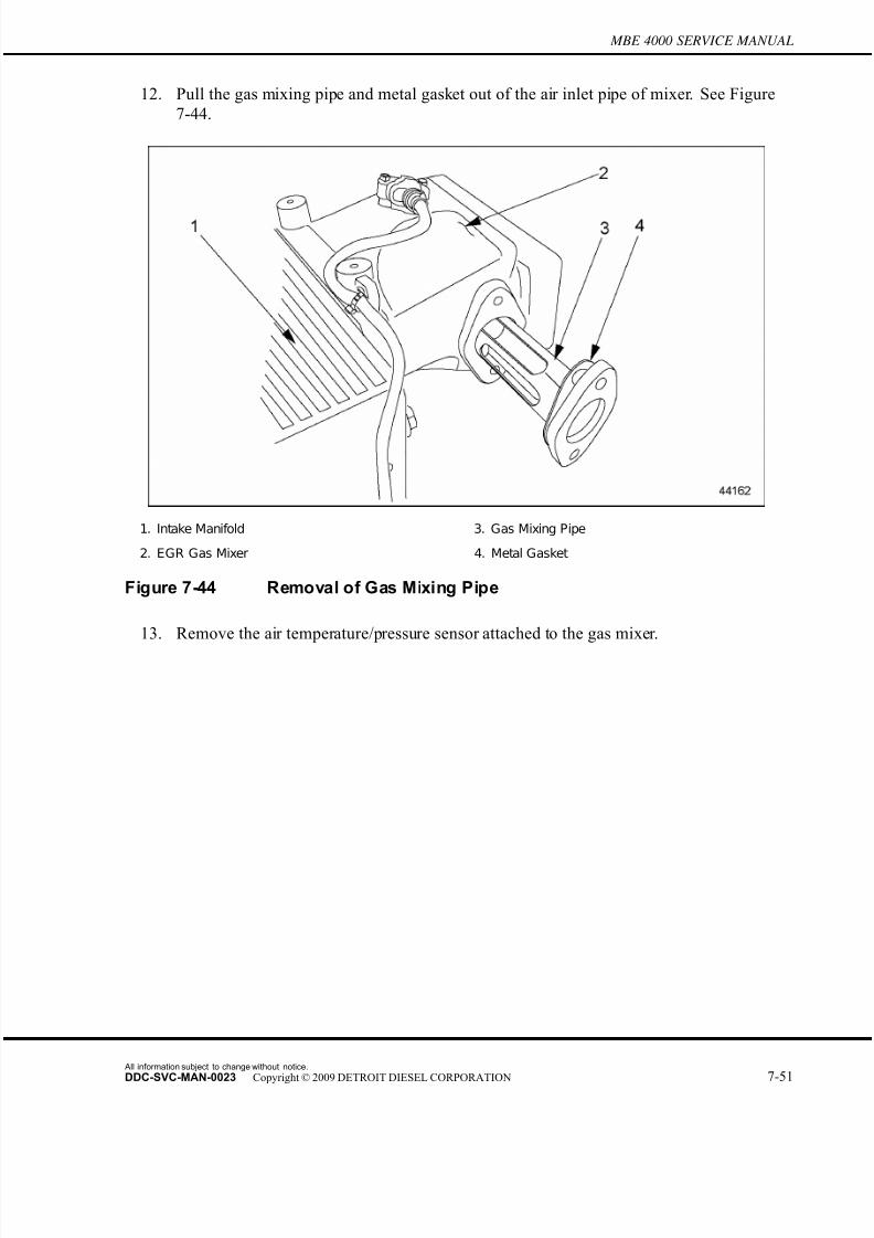
7/22/2019 Manual Mbe 4000 Taller
http://slidepdf.com/reader/full/manual-mbe-4000-taller 475/630
MBE 4000 SERVICE MANUAL
12. Pull the gas mixing pipe and metal gasket out of the air inlet pipe of mixer. See Figure
7-44.
1. Intake Manifold 3. Gas Mixing Pipe
2. EGR Gas Mixer 4. Metal Gasket
Figure 7-44 Removal of Gas Mixing Pipe
13. Remove the air temperature/pressure sensor attached to the gas mixer.
All information subject to change without notice.
DDC-SVC-MAN-0023 Copyright © 2009 DETROIT DIESEL CORPORATION 7-51
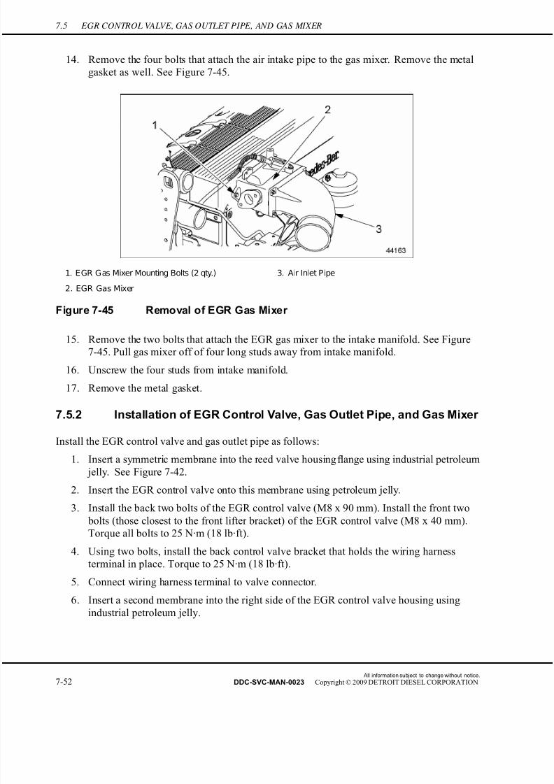
7/22/2019 Manual Mbe 4000 Taller
http://slidepdf.com/reader/full/manual-mbe-4000-taller 476/630
7.5 EGR CONTROL VALVE, GAS OUTLET PIPE, AND GAS MIXER
14. Remove the four bolts that attach the air intake pipe to the gas mixer. Remove the metal
gasket as well. See Figure 7-45.
1. EGR Gas Mixer Mounting Bolts (2 qty.) 3. Air Inlet Pipe
2. EGR Gas Mixer
Figure 7-45 Removal of EGR Gas Mixer
15. Remove the two bolts that attach the EGR gas mixer to the intake manifold. See Figure
7-45. Pull gas mixer off of four long studs away from intake manifold.
16. Unscrew the four studs from intake manifold.
17. Remove the metal gasket.
7.5.2 Installation of EGR Control Valve, Gas Outlet Pipe, and Gas Mixer
Install the EGR control valve and gas outlet pipe as follows:
1. Insert a symmetric membrane into the reed valve housing flange using industrial petroleum
jelly. See Figure 7-42.
2. Insert the EGR control valve onto this membrane using petroleum jelly.
3. Install the back two bolts of the EGR control valve (M8 x 90 mm). Install the front two
bolts (those closest to the front lifter bracket) of the EGR control valve (M8 x 40 mm).
Torque all bolts to 25 N·m (18 lb·ft).
4. Using two bolts, install the back control valve bracket that holds the wiring harnessterminal in place. Torque to 25 N·m (18 lb·ft).
5. Connect wiring harness terminal to valve connector.
6. Insert a second membrane into the right side of the EGR control valve housing using
industrial petroleum jelly.
All information subject to change without notice.
7-52 DDC-SVC-MAN-0023 Copyright © 2009 DETROIT DIESEL CORPORATION

7/22/2019 Manual Mbe 4000 Taller
http://slidepdf.com/reader/full/manual-mbe-4000-taller 477/630
MBE 4000 SERVICE MANUAL
7. Taking the EGR gas outlet pipe in hand, fit component manually onto symmetric
membrane, using petroleum jelly.
8. Install the four gas mixer mounting studs into the intake manifold.
9. Install metal gasket over studs.
10. Fit gas mixer over mounting studs and push on as far as possible.
11. Install the gas mixing pipe into the air inlet pipe of mixer using a new metal gasket.
See Figure 7-44.
NOTICE:
To avoid any engine damage, ensure thatthe gas passage ofthemixing pipe is turned towards the intake manifold.
NOTE:Due to its awkward shape, gas outlet pipe must be mounted to gas mixer before the gasmixer can befirmly attached to intake manifold.
12. Mount gas outlet pipe to gas mixer using a new metal gasket and two M8 x 16 mm
bolts. Adjust gas mixer if necessary to accommodate the gas outlet pipe. Torque to 25
N·m (18 lb·ft).
13. Position support bracket in place for gas outlet pipe. Install bracket using three M8 x
16 mm bolts. Torque to 25 N·m (18 lb·ft).
14. Install the air inlet pipe to the gas mixer using four nuts. Torque to 50 N·m (37 lb·ft).
See Figure 7-45.
15. Install the turbo boost/air intake temperature sensor to the gas mixer.
All information subject to change without notice.
DDC-SVC-MAN-0023 Copyright © 2009 DETROIT DIESEL CORPORATION 7-53

7/22/2019 Manual Mbe 4000 Taller
http://slidepdf.com/reader/full/manual-mbe-4000-taller 478/630
7.6 EPV (ELECTRONIC PROPORTIONAL VALVE) AND WABCO® AIR SOLENOID VALVE
7.6 EPV (ELECTRONIC PROPORTIONAL VALVE) AND WABCO® AIRSOLENOID VALVE
Listed in Table 7-4 is each proportional valve listed and the component it activates.
Proportional Valve Component
PV1 Exhaust flap enable + EGR shutoff valve or boost
control = wastegate valve (Turbobrake)
PV2 EGR control valve
PV3 Fan
PV4 Fan
PV5 CTV (Constant Throttle Valve)
PV6 Turbobrake sliding sleeve + EGR shutoff valve
Table 7-4 Proportional Valve Chart
7.6.1 Removal of EPV Valve and Wabco Air Solenoid Valve
Perform the following steps to remove the EPV valve, Wabco air solenoid valve and all the
corresponding connections:
1. Disconnect wiring harness from the EPV valve and the Wabco solenoid valve.
All information subject to change without notice.
7-54 DDC-SVC-MAN-0023 Copyright © 2009 DETROIT DIESEL CORPORATION

7/22/2019 Manual Mbe 4000 Taller
http://slidepdf.com/reader/full/manual-mbe-4000-taller 479/630
MBE 4000 SERVICE MANUAL
PERSONAL INJURY
To avoid injury from the sudden release of a high-pressurehose connection, wear a face shield or goggles.
2. Disconnect the compressed air pipe between inlet connection installed at EPV valve
and turbo brake actuator. See Figure 7-46.
1. EPV (Electronic Proportional Valve) 6. Large Hollow Screw
2. Wastegate 7. Small Hollow Screw
3. Electric Wiring Harness Terminals 8. EPV Valve Inlet
4. Wabco Valve 9. EPV Valve Outlet (hidden)
5. Solenoid Valve Mounting Bolts 10. EP V Valve Mounting Bolts
Figure 7-46 Removing the EPV Valve / Wabco Solenoid Valve
3. Remove the smaller hollow screw below the larger hollow screw.
4. Disconnect the inlet and outlet connections at EPV pressure regulating valve.
5. Remove the large hollow screw in threaded connection.
6. Remove the two M8 x 50 mm bolts that hold the EPV valve on the left side of bracket.
7. Remove the two M8 x 50 mm bolts that hold the Wabco solenoid valve on the right side
of bracket.
All information subject to change without notice.
DDC-SVC-MAN-0023 Copyright © 2009 DETROIT DIESEL CORPORATION 7-55
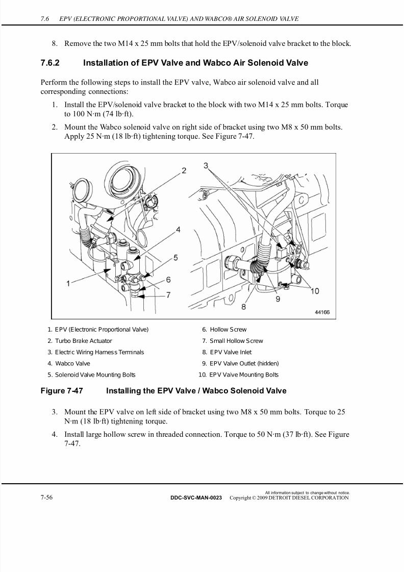
7/22/2019 Manual Mbe 4000 Taller
http://slidepdf.com/reader/full/manual-mbe-4000-taller 480/630
7.6 EPV (ELECTRONIC PROPORTIONAL VALVE) AND WABCO® AIR SOLENOID VALVE
8. Remove the two M14 x 25 mm bolts that hold the EPV/solenoid valve bracket to the block.
7.6.2 Installation of EPV Valve and Wabco Air Solenoid Valve
Perform the following steps to install the EPV valve, Wabco air solenoid valve and all
corresponding connections:
1. Install the EPV/solenoid valve bracket to the block with two M14 x 25 mm bolts. Torque
to 100 N·m (74 lb·ft).
2. Mount the Wabco solenoid valve on right side of bracket using two M8 x 50 mm bolts.
Apply 25 N·m (18 lb·ft) tightening torque. See Figure 7-47.
1. EPV (Electronic Proportional Valve) 6. Hollow Screw
2. Turbo Brake Actuator 7. Small Hollow Screw
3. Electric Wiring Harness Terminals 8. EPV Valve Inlet
4. Wabco Valve 9. EPV Valve Outlet (hidden)
5. Solenoid Valve Mounting Bolts 10. EP V Valve Mounting Bolts
Figure 7-47 Installing the EPV Valve / Wabco Solenoid Valve
3. Mount the EPV valve on left side of bracket using two M8 x 50 mm bolts. Torque to 25
N·m (18 lb·ft) tightening torque.
4. Install large hollow screw in threaded connection. Torque to 50 N·m (37 lb·ft). See Figure
7-47.
All information subject to change without notice.
7-56 DDC-SVC-MAN-0023 Copyright © 2009 DETROIT DIESEL CORPORATION
7/22/2019 Manual Mbe 4000 Taller
http://slidepdf.com/reader/full/manual-mbe-4000-taller 481/630
MBE 4000 SERVICE MANUAL
PERSONAL INJURY
To avoid injury from the sudden release of a high-pressurehose connection, wear a face shield or goggles.
5. Install inlet and outlet connections at EPV pressure regulating valve. Torque to 15 N·m
(11 lb·ft).
NOTICE:
Avoid friction on compressed air pipe traveling under theEP V valve or potential damage to engine could result.
6. Install smaller hollow screw below larger hollow screw, securing connection. Torque to
15 N·m (11 lb·ft).
7. Fit the pipe between inlet connection installed at EPV valve and turbo brake actuator.
8. Connect wiring harness to EPV valve and Wabco valve.
All information subject to change without notice.
DDC-SVC-MAN-0023 Copyright © 2009 DETROIT DIESEL CORPORATION 7-57
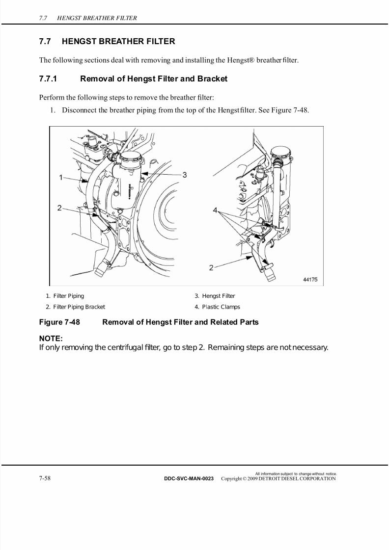
7/22/2019 Manual Mbe 4000 Taller
http://slidepdf.com/reader/full/manual-mbe-4000-taller 482/630
7.7 HENGST BREATHER FILTER
7.7 HENGST BREATHER FILTER
The following sections deal with removing and installing the Hengst® breather filter.
7.7.1 Removal of Hengst Filter and Bracket
Perform the following steps to remove the breather filter:
1. Disconnect the breather piping from the top of the Hengst filter. See Figure 7-48.
1. Filter Piping 3. Hengst Filter
2. Filter Piping Bracket 4. Plastic Clamps
Figure 7-48 Removal of Hengst Filter and Related Parts
NOTE:If only removing the centrifugalfilter, go to step 2. Remaining steps are not necessary.
All information subject to change without notice.
7-58 DDC-SVC-MAN-0023 Copyright © 2009 DETROIT DIESEL CORPORATION

7/22/2019 Manual Mbe 4000 Taller
http://slidepdf.com/reader/full/manual-mbe-4000-taller 483/630
MBE 4000 SERVICE MANUAL
2. Unsnap the filter cap and remove the spring and diaphragm from centrifugal filter.
Remove the two assembly bolts from the breather filter housing assembly, and remove the
centrifugal filter. See Figure 7-49.
1. Filter Cap 4. Breather Housing
2. Spring and Diaphragm 5. Assembly Bolt
3. Centrifugal Filter
Figure 7-49 Hengst Filter Assembly
3. Unclip the three plastic clamps holding the breather piping to the bracket and remove the
piping. See Figure 7-48.
4. Remove the two bolts from the air compressor and the block that are securing the piping
bracket and remove the piping bracket.
5. Remove the three M8 x 35 mm bolts holding the breather filter to the flywheel housing.
6. Remove the breather housing from the block tube housing on flywheel housing.
7. Remove the breather housing gasket, seal ring, and washer, if applicable. See Figure 7-50.
If breather contains the former style of seal ring, remove it from the groove in the breather
housing. Discard gasket, seal ring, and washer. See Figure 7-51.
All information subject to change without notice.
DDC-SVC-MAN-0023 Copyright © 2009 DETROIT DIESEL CORPORATION 7-59
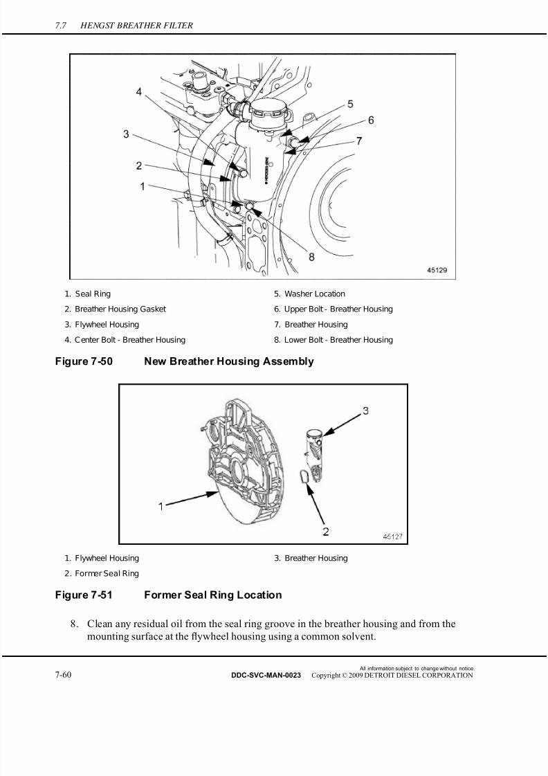
7/22/2019 Manual Mbe 4000 Taller
http://slidepdf.com/reader/full/manual-mbe-4000-taller 484/630
7.7 HENGST BREATHER FILTER
1. Seal Ring 5. Washer Location
2. Breather Housing Gasket 6. Upper Bolt - Breather Housing
3. Flywheel Housing 7. Breather Housing
4. Center Bolt - Breather Housing 8. Lower Bolt - Breather Housing
Figure 7-50 New Breather Housing Assembly
1. Flywheel Housing 3. Breather Housing
2. Former Seal Ring
Figure 7-51 Former Seal Ring Location
8. Clean any residual oil from the seal ring groove in the breather housing and from the
mounting surface at the flywheel housing using a common solvent.
All information subject to change without notice.
7-60 DDC-SVC-MAN-0023 Copyright © 2009 DETROIT DIESEL CORPORATION
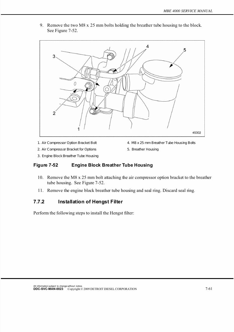
7/22/2019 Manual Mbe 4000 Taller
http://slidepdf.com/reader/full/manual-mbe-4000-taller 485/630
MBE 4000 SERVICE MANUAL
9. Remove the two M8 x 25 mm bolts holding the breather tube housing to the block.
See Figure 7-52.
1. Air Compressor Option Bracket Bolt 4. M8 x 25 mm Breather Tube Housing Bolts
2. Air Compressor Bracket for Options 5. Breather Housing
3. Engine Block Breather Tube Housing
Figure 7-52 Engine Block Breather Tube Housing
10. Remove the M8 x 25 mm bolt attaching the air compressor option bracket to the breather
tube housing. See Figure 7-52.
11. Remove the engine block breather tube housing and seal ring. Discard seal ring.
7.7.2 Installation of Hengst Filter
Perform the following steps to install the Hengst filter:
All information subject to change without notice.
DDC-SVC-MAN-0023 Copyright © 2009 DETROIT DIESEL CORPORATION 7-61

7/22/2019 Manual Mbe 4000 Taller
http://slidepdf.com/reader/full/manual-mbe-4000-taller 486/630
7.7 HENGST BREATHER FILTER
1. Install the engine block breather tube housing and new seal ring to the block using two M8
x 25 mm bolts. Torque bolts to 25 N·m (18 lb·ft). See Figure 7-53.
1. Air Compressor Option Bracket Bolt 4. M8 x 25 mm Breather Tube Housing Bolts
2. Air Compressor Bracket for Options 5. Breather Housing
3. Engine Block Breather Tube Housing
Figure 7-53 Engine Block Breather Tube Housing
NOTE:If installing centrifugal filter only, go to step 2. Remaining steps are not necessary.
All information subject to change without notice.
7-62 DDC-SVC-MAN-0023 Copyright © 2009 DETROIT DIESEL CORPORATION
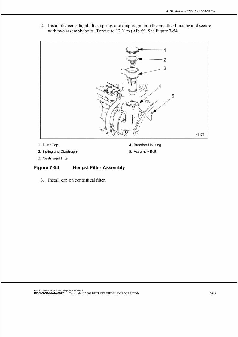
7/22/2019 Manual Mbe 4000 Taller
http://slidepdf.com/reader/full/manual-mbe-4000-taller 487/630
MBE 4000 SERVICE MANUAL
2. Install the centrifugal filter, spring, and diaphragm into the breather housing and secure
with two assembly bolts. Torque to 12 N·m (9 lb·ft). See Figure 7-54.
1. Filter Cap 4. Breather Housing
2. Spring and Diaphragm 5. Assembly Bolt
3. Centrifugal Filter
Figure 7-54 Hengst Filter Assembly
3. Install cap on centrifugal filter.
All information subject to change without notice.
DDC-SVC-MAN-0023 Copyright © 2009 DETROIT DIESEL CORPORATION 7-63

7/22/2019 Manual Mbe 4000 Taller
http://slidepdf.com/reader/full/manual-mbe-4000-taller 488/630
7.7 HENGST BREATHER FILTER
4. Install the new breather housing gasket between the breather housing and the flywheel
housing. See Figure 7-55.
1. Seal Ring Washer 5. Washer Location
2. Breather Housing Gasket 6. Upper Bolt - Breather Housing
3. Flywheel Housing 7. Breather Housing
4. Center Bolt - Breather Housing 8. Lower Bolt - Breather Housing
Figure 7-55 New Breather Housing Assembly
5. Install the new seal ring washer at the lower bolt location of the breather housing.
See Figure 7-55.
6. Add the new washer at the upper bolt location behind the breather housing to compensate
for the thickness of the breather housing gasket. See Figure 7-55.
7. Insert the upper opening of the breather housing onto the engine block breather tube
housing.
All information subject to change without notice.
7-64 DDC-SVC-MAN-0023 Copyright © 2009 DETROIT DIESEL CORPORATION

7/22/2019 Manual Mbe 4000 Taller
http://slidepdf.com/reader/full/manual-mbe-4000-taller 489/630
MBE 4000 SERVICE MANUAL
8. Install all three M8 x 35 mm breather housing bolts and torque to 25 N·m (18 lb·ft).
1. Filter Piping 3. Hengst Filter
2. Filter Piping Bracket 4. Plastic Clamps
Figure 7-56 Installation of Hengst Filter and Related Parts
9. Attach the filter piping bracket to the air compressor and block as follows:
[a] Install a M14 x 60 mm bolt with a spacer at the engine block. Torque to 100 N·m(74 lb·ft).
[b] Install a M10 x 35 mm bolt at the air compressor. Torque to 60 N·m (44 lb·ft).
10. Connect filter pipe to the top of the Hengst filter.
11. Secure filter pipe with three plastic clamps to pipe bracket. See Figure 7-56.
All information subject to change without notice.
DDC-SVC-MAN-0023 Copyright © 2009 DETROIT DIESEL CORPORATION 7-65
7/22/2019 Manual Mbe 4000 Taller
http://slidepdf.com/reader/full/manual-mbe-4000-taller 490/630
7.7 HENGST BREATHER FILTER
All information subject to change without notice.
7-66 DDC-SVC-MAN-0023 Copyright © 2009 DETROIT DIESEL CORPORATION
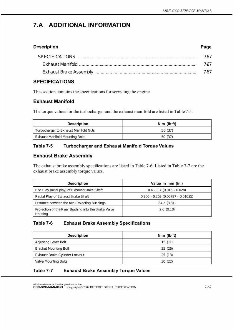
7/22/2019 Manual Mbe 4000 Taller
http://slidepdf.com/reader/full/manual-mbe-4000-taller 491/630
MBE 4000 SERVICE MANUAL
7.A ADDITIONAL INFORMATION
Description Page
SP ECIFICATIONS ............................................................................................. 7-67Exhaust Manifold ............................................................................................ 7-67
Exhaust Brake Assembly ............................................................................... 7-67
SPECIFICATIONS
This section contains the specifications for servicing the engine.
Exhaust Manifold
The torque values for the turbocharger and the exhaust manifold are listed in Table 7-5.
Description N·m (lb·ft)
Turbocharger to Exhaust Manifold Nuts 50 (37)
Exhaust Manifold Mounting Bolts 50 (37)
Table 7-5 Turbocharger and Exhaust Manifold Torque Values
Exhaust Brake Assembly
The exhaust brake assembly specifications are listed in Table 7-6. Listed in Table 7-7 are the
exhaust brake assembly torque values.
Description Value in mm (in.)
E nd P lay (axial play) of E xhaust B rake S haft 0.4 - 0.7 (0.016 - 0.028)
Radial P lay of E xhaust B rake S haft 0.200 - 0.263 (0.00787 - 0.01035)
Distance between the two P rojecting Bushings, 84.2 (3.31)
Projection of the Rear Bushing into the Brake Valve
Housing
2.6 (0.10)
Table 7-6 Exhaust Brake Assembly Specifications
Description N·m (lb·ft)
Adjusting Lever Bolt 15 (11)
Bracket Mounting Bolt 35 (26)
Exhaust Brake Cylinder Locknut 25 (18)
Valve Mounting Bolts 30 (22)
Table 7-7 Exhaust Brake Assembly Torque Values
All information subject to change without notice.
DDC-SVC-MAN-0023 Copyright © 2009 DETROIT DIESEL CORPORATION 7-67

7/22/2019 Manual Mbe 4000 Taller
http://slidepdf.com/reader/full/manual-mbe-4000-taller 492/630
All information subject to change without notice.
7-68 DDC-SVC-MAN-0023 Copyright © 2009 DETROIT DIESEL CORPORATION
7/22/2019 Manual Mbe 4000 Taller
http://slidepdf.com/reader/full/manual-mbe-4000-taller 493/630
8 ELECTRICAL EQUIPMENT
Section Page
8.1 DRIVE BELTS .......................................................................................... 8-3
8.A ADDITIONAL INFORMATION .................................................................. 8-15

7/22/2019 Manual Mbe 4000 Taller
http://slidepdf.com/reader/full/manual-mbe-4000-taller 494/630
All information subject to change without notice.
8-2 DDC-SVC-MAN-0023 Copyright © 2009 DETROIT DIESEL CORPORATION

7/22/2019 Manual Mbe 4000 Taller
http://slidepdf.com/reader/full/manual-mbe-4000-taller 495/630
MBE 4000 SERVICE MANUAL
8.1 DRIVE BELTS
There are three v-ribbed drive belts on the MBE 4000 engine:
□ The main drive belt — (nine ribs)
□ The fan belt — (eight ribs)
□ The air conditioner compressor belt (installed only on vehicles with air conditioning) —
(six ribs)
The main drive belt has nine ribs and drives the alternator and coolant pump. The fan belt has
eight ribs and the air conditioner compressor belt (if installed) has six ribs.
NOTE:Before removing and installing a belt, check belt function and make sure to install thecorrect belt.
There are three idler pulleys on the MBE 4000 engine, one on the main drive belt and two on the
fan belt. One of the fan belt idler pulleys has a ribbed belt contact surface; the others are smooth.
There is no idler pulley installed for the air conditioner compressor belt.
8.1.1 Main Drive Belt Removal
Remove the main drive belt as follows:
NOTE: There are three v-ribbed drive belts on the MBE 4000 engine. Be sure to remove andinstall the correct belt(s).
1. Disconnect the batteries.
All information subject to change without notice.
DDC-SVC-MAN-0023 Copyright © 2009 DETROIT DIESEL CORPORATION 8-3

7/22/2019 Manual Mbe 4000 Taller
http://slidepdf.com/reader/full/manual-mbe-4000-taller 496/630
8.1 DRIVE BELTS
2. Release the tension on the main drive belt. See Figure 8-1.
1. Alternator 3. Belt Tensioner
2. Main Drive Belt 4. Socket Wrench
Figure 8-1 Releasing Belt Tension
[a] Place a socket wrench on the tensioner pulley bolt.
[b] Pull the socket wrench (swivel the tensioner pulley counterclockwise) to removethe tension from the belt.
[c] Hold the tensioner pulley in this position for the next step.
All information subject to change without notice.
8-4 DDC-SVC-MAN-0023 Copyright © 2009 DETROIT DIESEL CORPORATION

7/22/2019 Manual Mbe 4000 Taller
http://slidepdf.com/reader/full/manual-mbe-4000-taller 497/630
MBE 4000 SERVICE MANUAL
3. Remove the drive belt from the alternator, coolant-pump and idler pulleys. Be careful not
to kink, stretch, or otherwise damage the belt. See Figure 8-2.
1. Vibration Damper 4. Idler Pulley
2. Tensioner Pulley 5. Main Drive Belt
3. Alternator Pulley 6. Coolant Pump Pulley
Figure 8-2 Main Drive Belt Removal
4. Release the tensioner pulley.
5. Inspect the drive belt for nicks, wear, or other damage. Replace the belt if necessary.
6. Inspect the following parts and replace any that are damaged or worn:
□ vibration damper
□ alternator pulley
□ coolant-pump pulley
□ belt tensioner
□ tensioner pulley
□ idler pulley
8.1.2 Main Drive Belt Installation
Install the main drive belt as follows:
All information subject to change without notice.
DDC-SVC-MAN-0023 Copyright © 2009 DETROIT DIESEL CORPORATION 8-5
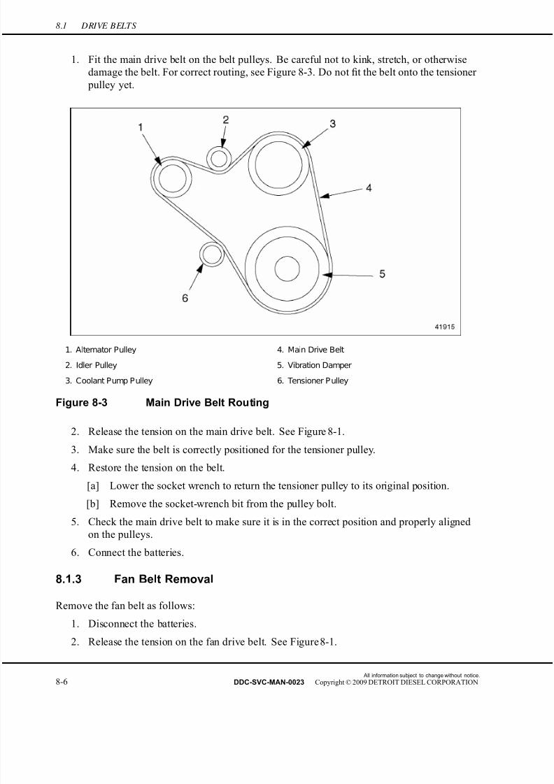
7/22/2019 Manual Mbe 4000 Taller
http://slidepdf.com/reader/full/manual-mbe-4000-taller 498/630
8.1 DRIVE BELTS
1. Fit the main drive belt on the belt pulleys. Be careful not to kink, stretch, or otherwise
damage the belt. For correct routing, see Figure 8-3. Do not fit the belt onto the tensioner
pulley yet.
1. Alternator Pulley 4. Main Drive Belt
2. Idler Pulley 5. Vibration Damper
3. Coolant Pump Pulley 6. Tensioner P ulley
Figure 8-3 Main Drive Belt Routing
2. Release the tension on the main drive belt. See Figure 8-1.
3. Make sure the belt is correctly positioned for the tensioner pulley.
4. Restore the tension on the belt.
[a] Lower the socket wrench to return the tensioner pulley to its original position.
[b] Remove the socket-wrench bit from the pulley bolt.
5. Check the main drive belt to make sure it is in the correct position and properly aligned
on the pulleys.
6. Connect the batteries.
8.1.3 Fan Belt Removal
Remove the fan belt as follows:
1. Disconnect the batteries.
2. Release the tension on the fan drive belt. See Figure 8-1.
All information subject to change without notice.
8-6 DDC-SVC-MAN-0023 Copyright © 2009 DETROIT DIESEL CORPORATION
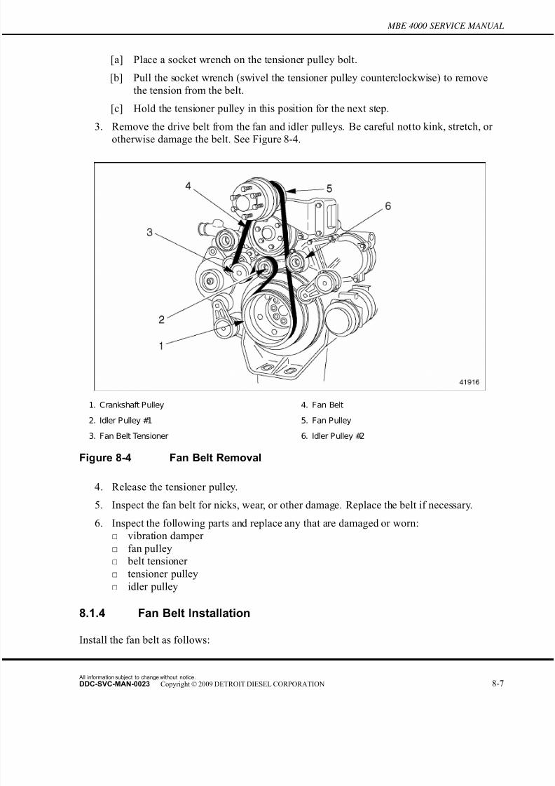
7/22/2019 Manual Mbe 4000 Taller
http://slidepdf.com/reader/full/manual-mbe-4000-taller 499/630
MBE 4000 SERVICE MANUAL
[a] Place a socket wrench on the tensioner pulley bolt.
[b] Pull the socket wrench (swivel the tensioner pulley counterclockwise) to remove
the tension from the belt.
[c] Hold the tensioner pulley in this position for the next step.
3. Remove the drive belt from the fan and idler pulleys. Be careful not to kink, stretch, or
otherwise damage the belt. See Figure 8-4.
1. Crankshaft Pulley 4. Fan Belt
2. Idler Pulley #1 5. Fan Pulley
3. Fan Belt Tensioner 6. Idler Pulley #2
Figure 8-4 Fan Belt Removal
4. Release the tensioner pulley.
5. Inspect the fan belt for nicks, wear, or other damage. Replace the belt if necessary.
6. Inspect the following parts and replace any that are damaged or worn:
□ vibration damper
□ fan pulley□ belt tensioner
□ tensioner pulley
□ idler pulley
8.1.4 Fan Belt Installation
Install the fan belt as follows:
All information subject to change without notice.
DDC-SVC-MAN-0023 Copyright © 2009 DETROIT DIESEL CORPORATION 8-7

7/22/2019 Manual Mbe 4000 Taller
http://slidepdf.com/reader/full/manual-mbe-4000-taller 500/630
8.1 DRIVE BELTS
1. Fit the fan drive belt on the belt pulleys. Be careful not to kink, stretch, or otherwise
damage the belt. For correct routing, see Figure 8-5. Do not fit the belt onto the tensioner
pulley yet.
1. Tensioner Pulley 4. Idler Pulley #2
2. Idler Pulley #1 5. Fan Belt
3. Fan Pulley 6. Crankshaft Pulley
Figure 8-5 Fan Belt Routing
2. Release the tension on the fan belt. See Figure 8-1.
3. Make sure the belt is correctly positioned for the tensioner pulley.
4. Restore the tension on the belt.
[a] Lower the socket wrench to return the tensioner pulley to its original position.
[b] Remove the socket-wrench bit from the pulley bolt.
5. Check the fan belt to make sure it is in the correct position and properly aligned on the
pulleys.
6. Connect the batteries.
8.1.5 Air Conditioner Compressor Belt Removal
Install the air conditioner (A/C) compressor belt as follows:
NOTE: The A/C compressor belt is installed only on vehicles with air conditioning.
All information subject to change without notice.
8-8 DDC-SVC-MAN-0023 Copyright © 2009 DETROIT DIESEL CORPORATION

7/22/2019 Manual Mbe 4000 Taller
http://slidepdf.com/reader/full/manual-mbe-4000-taller 501/630
MBE 4000 SERVICE MANUAL
1. Disconnect the batteries.
2. Release the tension on the A/C compressor drive belt. See Figure 8-1.
[a] Place a socket wrench on the tensioner pulley bolt.
[b] Pull the socket wrench (swivel the tensioner pulley clockwise) to remove the tension
from the belt.
[c] Hold the tensioner pulley in this position for the next step.
3. Remove the drive belt from the A/C compressor pulley. Be careful not to kink, stretch, or
otherwise damage the belt. See Figure 8-6.
1. Crankshaft Pulley 3. A/C Compressor Belt
2. A/C Compressor Belt Tensioner 4. A/C Compressor Pulley
Figure 8-6 Air Conditioner Compressor Belt Removal
4. Release the tensioner pulley.
5. Inspect the A/C compressor belt for nicks, wear, or other damage. Replace the belt if
necessary.
6. Inspect the following parts and replace any that are damaged or worn:
□ vibration damper
□ A/C compressor pulley
□ belt tensioner
□ tensioner pulley
□ idler pulley
All information subject to change without notice.
DDC-SVC-MAN-0023 Copyright © 2009 DETROIT DIESEL CORPORATION 8-9

7/22/2019 Manual Mbe 4000 Taller
http://slidepdf.com/reader/full/manual-mbe-4000-taller 502/630
8.1 DRIVE BELTS
8.1.6 Air Conditioner Compressor Belt Installation
Install the A/C compressor belt as follows:
1. Fit the A/C compressor drive belt on the belt pulleys. Be careful not to kink, stretch, or
otherwise damage the belt. For correct routing, see Figure 8-7. Do not fit the belt onto
the tensioner pulley yet.
1. Tensioner Pulley 3. Crankshaft Pulley
2. A/C Compressor Pulley
Figure 8-7 Air Conditioner Compressor Belt Routing
2. Release the tension on the A/C compressor belt. See Figure 8-1.
3. Make sure the belt is correctly positioned for the tensioner pulley.
4. Restore the tension on the belt.
[a] Lower the socket wrench to return the tensioner pulley to its original position.
[b] Remove the socket-wrench bit from the pulley bolt.
5. Check the A/C compressor belt to make sure it is in the correct position and properlyaligned on the pulleys.
6. Connect the batteries.
All information subject to change without notice.
8-10 DDC-SVC-MAN-0023 Copyright © 2009 DETROIT DIESEL CORPORATION

7/22/2019 Manual Mbe 4000 Taller
http://slidepdf.com/reader/full/manual-mbe-4000-taller 503/630
MBE 4000 SERVICE MANUAL
8.1.7 Belt Tensioner Removal
Remove the belt tensioner as follows:
NOTE: This procedure works for all belt tensioners. See Figure 8-8 to identify the correct belt
tensioner.
1. Main Drive Belt Tensioner 4. Mounting Pad
2. Fan Belt Tensioner 5. Socket-Head Mounting Bolt
3. A/C Compressor Belt Tensioner
Figure 8-8 Belt Tensioners
PERSONAL INJURY
To avoid injury to hands and fingers from the spring-loadedauto belt tensioner violently snapping back, do not cut thebelt to remove it.
1. Release the tension on the main drive belt (alternator and coolant pump), fan belt, and/or
A/C compressor belt, as desired. Refer to section 8.1.1.
2. Release the tensioning pulley.
3. Remove the mounting bolt that fastens the belt tensioner and tensioner pulley to the
cylinder block.
All information subject to change without notice.
DDC-SVC-MAN-0023 Copyright © 2009 DETROIT DIESEL CORPORATION 8-11
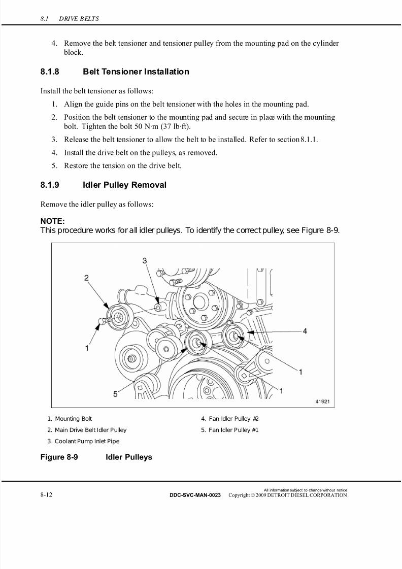
7/22/2019 Manual Mbe 4000 Taller
http://slidepdf.com/reader/full/manual-mbe-4000-taller 504/630
8.1 DRIVE BELTS
4. Remove the belt tensioner and tensioner pulley from the mounting pad on the cylinder
block.
8.1.8 Belt Tensioner Installation
Install the belt tensioner as follows:
1. Align the guide pins on the belt tensioner with the holes in the mounting pad.
2. Position the belt tensioner to the mounting pad and secure in place with the mounting
bolt. Tighten the bolt 50 N·m (37 lb·ft).
3. Release the belt tensioner to allow the belt to be installed. Refer to section 8.1.1.
4. Install the drive belt on the pulleys, as removed.
5. Restore the tension on the drive belt.
8.1.9 Idler Pulley Removal
Remove the idler pulley as follows:
NOTE: This procedure works for all idler pulleys. To identify the correct pulley, see Figure 8-9.
1. Mounting Bolt 4. Fan Idler Pulley #2
2. Main Drive Belt Idler Pulley 5. Fan Idler Pulley #1
3. Coolant Pump Inlet Pipe
Figure 8-9 Idler Pulleys
All information subject to change without notice.
8-12 DDC-SVC-MAN-0023 Copyright © 2009 DETROIT DIESEL CORPORATION

7/22/2019 Manual Mbe 4000 Taller
http://slidepdf.com/reader/full/manual-mbe-4000-taller 505/630
MBE 4000 SERVICE MANUAL
1. Release the tension on the main drive belt (alternator and coolant-pump), and/or fan belt,
as desired. Refer to section 8.1.1 for detailed instructions.
2. With belt tension relaxed, remove the belt from contact with the idler pulley.
3. Release the tensioning pulley.
4. Remove the cover from the idler pulley.
5. Remove the socket-head bolt fastening the pulley to the mounting pad.
6. Remove the pulley from the mounting pad.
8.1.10 Idler Pulley Installation
Install the idler pulley as follows:
1. Position the pulley on the mounting pad, as removed.
2. Secure the pulley with the socket-head bolt. Tighten the bolt 45 N·m (33 lb·ft).
3. Release the tension on the belt tensioner. Refer to section 8.1.1 for detailed instructions.4. Position the belt around the new pulley.
5. When the belt is in place, restore the tension on the drive belt. Refer to section 8.1.1
for detailed instructions.
6. Install the idler pulley cover.
8.1.11 Air Conditioner Compressor Pad Removal
Remove the A/C compressor pad as follows:
NOTE: The A/C compressor belt tensioner is attached to the A/C compressor pad.
1. Remove the A/C compressor.
2. Remove the belt tensioner from the pad.
All information subject to change without notice.
DDC-SVC-MAN-0023 Copyright © 2009 DETROIT DIESEL CORPORATION 8-13

7/22/2019 Manual Mbe 4000 Taller
http://slidepdf.com/reader/full/manual-mbe-4000-taller 506/630
8.1 DRIVE BELTS
3. Remove the bolts attaching the A/C compressor pad to the cylinder block. See Figure 8-10.
1. Belt Tensioner 3. Pad Mounting Hole
2. A/C Compressor Mounting Holes 4. A/C Compressor Mounting Pad
Figure 8-10 Air Conditioner Compressor Pad Removal
4. Remove the A/C compressor pad from the engine.
8.1.12 Air Conditioner Compressor Pad Installation
Install the A/C compressor pad as follows:
1. Position the A/C compressor pad on the cylinder block, as removed.
2. Install the mounting bolts and tighten them 150 N·m (110 lb·ft).
3. Install the belt tensioner on the pad.
4. Install the A/C compressor.
All information subject to change without notice.
8-14 DDC-SVC-MAN-0023 Copyright © 2009 DETROIT DIESEL CORPORATION

7/22/2019 Manual Mbe 4000 Taller
http://slidepdf.com/reader/full/manual-mbe-4000-taller 507/630
MBE 4000 SERVICE MANUAL
8.A ADDITIONAL INFORMATION
Description Page
SP ECIFICATIONS ............................................................................................. 8-15Drive Belts ...................................................................................................... 8-15
SPECIFICATIONS
This section contains the specifications for servicing the engine.
Drive Belts
The torque values for the drive belts are listed in Table 8-1.
Description Torque Value, N·m (lb·ft)
Socket-Head Mounting Bolt Belt Tensioner 50 (37)
Idler Pulley, Mounting Bolt 45 (33)
A/C Compressor Pad, Mounting Bolt 150 (110)
Table 8-1 Drive Belts Torque Values
All information subject to change without notice.
DDC-SVC-MAN-0023 Copyright © 2009 DETROIT DIESEL CORPORATION 8-15

7/22/2019 Manual Mbe 4000 Taller
http://slidepdf.com/reader/full/manual-mbe-4000-taller 508/630
All information subject to change without notice.
8-16 DDC-SVC-MAN-0023 Copyright © 2009 DETROIT DIESEL CORPORATION
7/22/2019 Manual Mbe 4000 Taller
http://slidepdf.com/reader/full/manual-mbe-4000-taller 509/630
9 POWER TAKE-OFF
Section Page
9.1 FRONT ENGINE POWER TAKE-OFF (FEPTO) ...................................... 9-3
9.2 REAR ENGINE POWER TAKE-OFF (REPTO) ........................................ 9-7

7/22/2019 Manual Mbe 4000 Taller
http://slidepdf.com/reader/full/manual-mbe-4000-taller 510/630
All information subject to change without notice.
9-2 DDC-SVC-MAN-0023 Copyright © 2009 DETROIT DIESEL CORPORATION
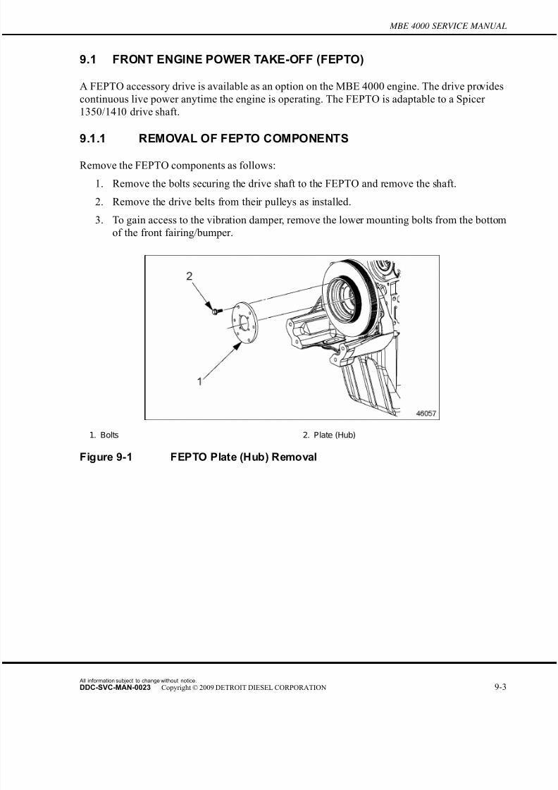
7/22/2019 Manual Mbe 4000 Taller
http://slidepdf.com/reader/full/manual-mbe-4000-taller 511/630
MBE 4000 SERVICE MANUAL
9.1 FRONT ENGINE POWER TAKE-OFF (FEPTO)
A FEPTO accessory drive is available as an option on the MBE 4000 engine. The drive provides
continuous live power anytime the engine is operating. The FEPTO is adaptable to a Spicer
1350/1410 drive shaft.
9.1.1 REMOVAL OF FEPTO COMPONENTS
Remove the FEPTO components as follows:
1. Remove the bolts securing the drive shaft to the FEPTO and remove the shaft.
2. Remove the drive belts from their pulleys as installed.
3. To gain access to the vibration damper, remove the lower mounting bolts from the bottom
of the front fairing/bumper.
1. Bolts 2. Plate (Hub)
Figure 9-1 FEPTO Plate (Hub) Removal
All information subject to change without notice.
DDC-SVC-MAN-0023 Copyright © 2009 DETROIT DIESEL CORPORATION 9-3
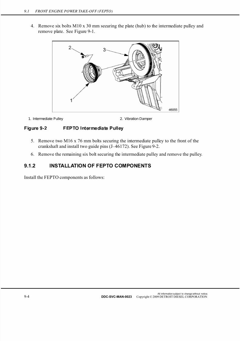
7/22/2019 Manual Mbe 4000 Taller
http://slidepdf.com/reader/full/manual-mbe-4000-taller 512/630
9.1 FRONT ENGINE POWER TAKE-OFF (FEPTO)
4. Remove six bolts M10 x 30 mm securing the plate (hub) to the intermediate pulley and
remove plate. See Figure 9-1.
1. Intermediate Pulley 2. Vibration Damper
Figure 9-2 FEPTO Intermediate Pulley
5. Remove two M16 x 76 mm bolts securing the intermediate pulley to the front of the
crankshaft and install two guide pins (J–46172). See Figure 9-2.
6. Remove the remaining six bolt securing the intermediate pulley and remove the pulley.
9.1.2 INSTALLATION OF FEPTO COMPONENTS
Install the FEPTO components as follows:
All information subject to change without notice.
9-4 DDC-SVC-MAN-0023 Copyright © 2009 DETROIT DIESEL CORPORATION

7/22/2019 Manual Mbe 4000 Taller
http://slidepdf.com/reader/full/manual-mbe-4000-taller 513/630
MBE 4000 SERVICE MANUAL
1. Install guide pins (J–46172) into the front of the crankshaft. See Figure 9-3.
1. Guide Pins (J -46172) 2. Crankshaft (Front)
Figure 9-3 Guide Pin Installation
2. Install the oil deflector and vibration damper over the guide pins. Ensure the rim on
the deflector is facing the engine.
1. Intermediate Pulley 3. Vibration Damper
Figure 9-4 Vibration Damper and Pulley
3. Install the immediate pulley over the guide pins. See Figure 9-4.
4. Install eight M16 x 76 mm mounting bolts and secure the intermediate pulley and the
vibration damper, Torque the bolts in a criss-cross pattern to 200 N·m (148 lb·ft). Ensure
all bolts have been tighten.
5. Remove the guide pins from the front of the crankshaft.
All information subject to change without notice.
DDC-SVC-MAN-0023 Copyright © 2009 DETROIT DIESEL CORPORATION 9-5
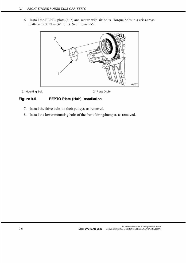
7/22/2019 Manual Mbe 4000 Taller
http://slidepdf.com/reader/full/manual-mbe-4000-taller 514/630
9.1 FRONT ENGINE POWER TAKE-OFF (FEPTO)
6. Install the FEPTO plate (hub) and secure with six bolts. Torque bolts in a criss-cross
pattern to 60 N·m (45 lb·ft). See Figure 9-5.
1. Mounting Bolt 2. Plate (Hub)
Figure 9-5 FEPTO Plate (Hub) Installation
7. Install the drive belts on their pulleys, as removed.
8. Install the lower mounting bolts of the front fairing/bumper, as removed.
All information subject to change without notice.
9-6 DDC-SVC-MAN-0023 Copyright © 2009 DETROIT DIESEL CORPORATION
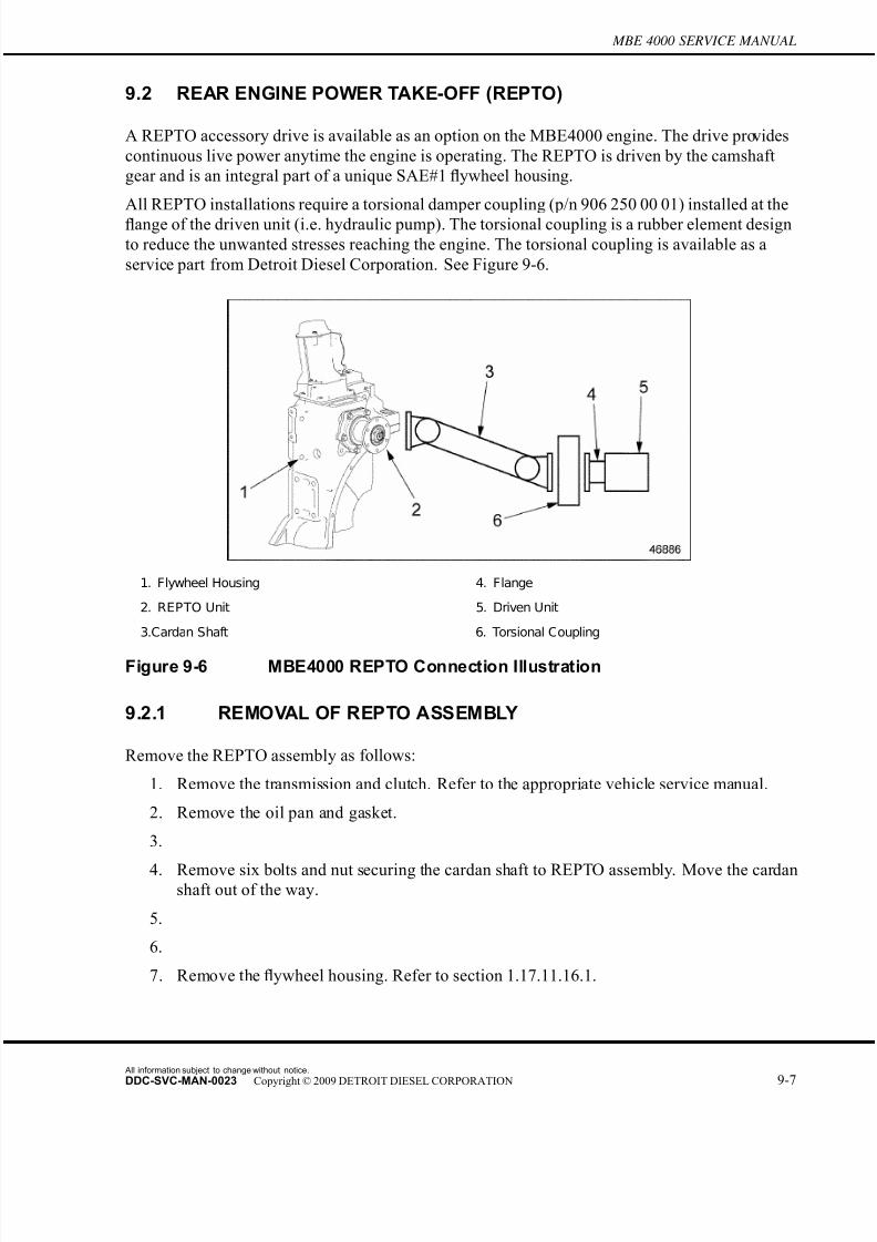
7/22/2019 Manual Mbe 4000 Taller
http://slidepdf.com/reader/full/manual-mbe-4000-taller 515/630
MBE 4000 SERVICE MANUAL
9.2 REAR ENGINE POWER TAKE-OFF (REPTO)
A REPTO accessory drive is available as an option on the MBE4000 engine. The drive provides
continuous live power anytime the engine is operating. The REPTO is driven by the camshaft
gear and is an integral part of a unique SAE#1 flywheel housing.
All REPTO installations require a torsional damper coupling (p/n 906 250 00 01) installed at the
flange of the driven unit (i.e. hydraulic pump). The torsional coupling is a rubber element design
to reduce the unwanted stresses reaching the engine. The torsional coupling is available as a
service part from Detroit Diesel Corporation. See Figure 9-6.
1. Flywheel Housing 4. Flange
2. REPTO Unit 5. Driven Unit
3.Cardan Shaft 6. Torsional Coupling
Figure 9-6 MBE4000 REPTO Connection Illustration
9.2.1 REMOVAL OF REPTO ASSEMBLY
Remove the REPTO assembly as follows:
1. Remove the transmission and clutch. Refer to the appropriate vehicle service manual.
2. Remove the oil pan and gasket.
3.
4. Remove six bolts and nut securing the cardan shaft to REPTO assembly. Move the cardanshaft out of the way.
5.
6.
7. Remove the flywheel housing. Refer to section 1.17.11.16.1.
All information subject to change without notice.
DDC-SVC-MAN-0023 Copyright © 2009 DETROIT DIESEL CORPORATION 9-7
7/22/2019 Manual Mbe 4000 Taller
http://slidepdf.com/reader/full/manual-mbe-4000-taller 516/630
9.2 REAR ENGINE POWER TAKE-OFF (REPTO)
All information subject to change without notice.
9-8 DDC-SVC-MAN-0023 Copyright © 2009 DETROIT DIESEL CORPORATION
7/22/2019 Manual Mbe 4000 Taller
http://slidepdf.com/reader/full/manual-mbe-4000-taller 517/630
10 SPECIAL EQUIPMENT
Section Page
10.1 AIR COMP RESS OR FLANGE ................................................................. 10-3
10.2 AIR COMP RESSOR ................................................................................ 10-5
10.A ADDITIONAL INFORMATION .................................................................. 10-11

7/22/2019 Manual Mbe 4000 Taller
http://slidepdf.com/reader/full/manual-mbe-4000-taller 518/630
All information subject to change without notice.
10-2 DDC-SVC-MAN-0023 Copyright © 2009 DETROIT DIESEL CORPORATION
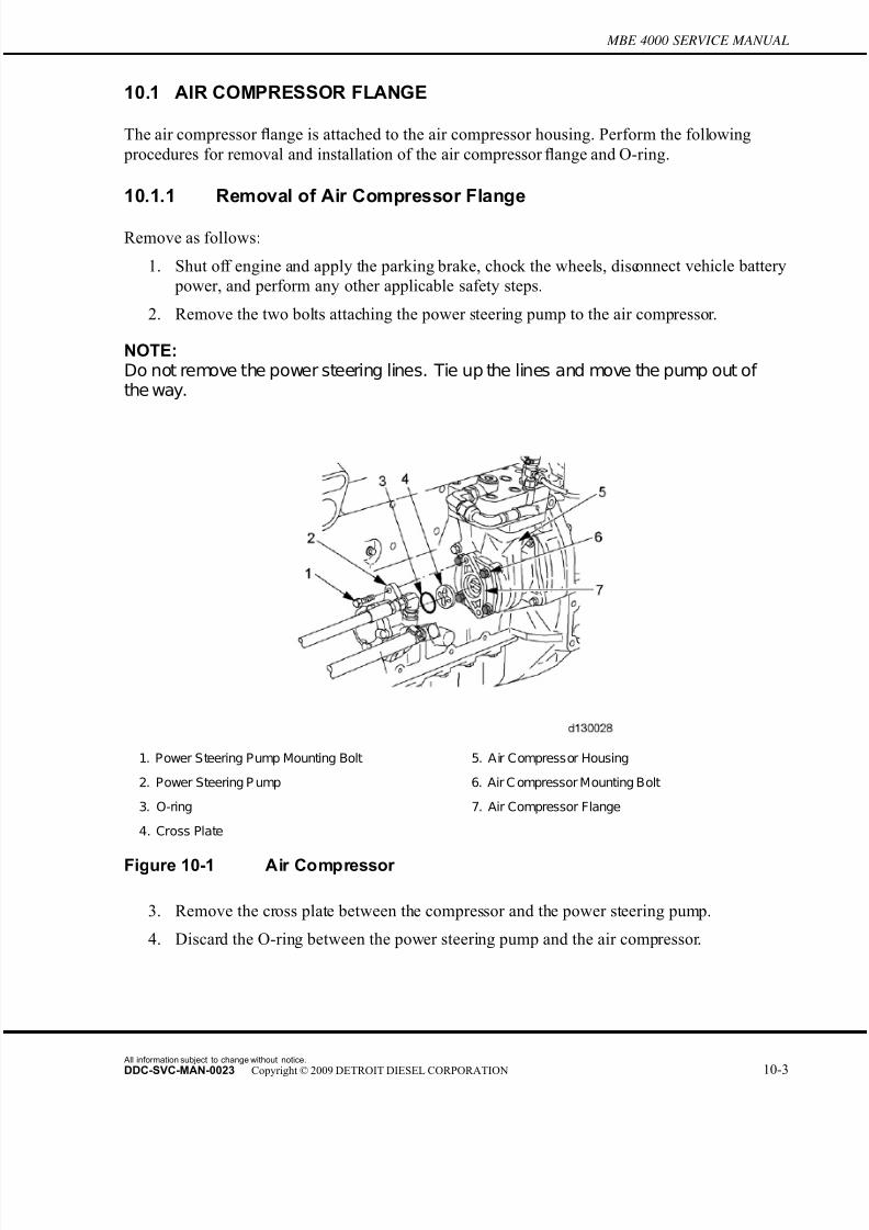
7/22/2019 Manual Mbe 4000 Taller
http://slidepdf.com/reader/full/manual-mbe-4000-taller 519/630
MBE 4000 SERVICE MANUAL
10.1 AIR COMPRESSOR FLANGE
The air compressor flange is attached to the air compressor housing. Perform the following
procedures for removal and installation of the air compressor flange and O-ring.
10.1.1 Removal of Air Compressor Flange
Remove as follows:
1. Shut off engine and apply the parking brake, chock the wheels, disconnect vehicle battery
power, and perform any other applicable safety steps.
2. Remove the two bolts attaching the power steering pump to the air compressor.
NOTE:Do not remove the power steering lines. Tie up the lines and move the pump out of the way.
1. Power Steering Pump Mounting Bolt 5. Air Compressor Housing
2. Power Steering P ump 6. Air C ompressor Mounting Bolt
3. O-ring 7. Air Compressor Flange
4. Cross Plate
Figure 10-1 Air Compressor
3. Remove the cross plate between the compressor and the power steering pump.
4. Discard the O-ring between the power steering pump and the air compressor.
All information subject to change without notice.
DDC-SVC-MAN-0023 Copyright © 2009 DETROIT DIESEL CORPORATION 10-3

7/22/2019 Manual Mbe 4000 Taller
http://slidepdf.com/reader/full/manual-mbe-4000-taller 520/630
10.1 AIR COMPRESSOR FLANGE
NOTICE:
When removing the flange, make sure not to damage thecrankshaft journal or crankshaft bearing.
5. Remove the four bolts attaching the air compressor flange to the air compressor housing.
6. Discard O-ring between the air compressor flange and air compressor housing.
7. Inspect air compressor flange, bearing, and O-ring surfaces for damage. Replace if
necessary.
10.1.2 Installation of Air Compressor Flange
Installation steps are as follows:
1. Install the new O-ring between the air compressor flange and air compressor housing.
NOTICE:
Make sure to not damage the crankshaft journal or crankshaftbearing while installing.
2. Install the air compressor flange using the four bolts. Torque to 30 N·m (22 lb·ft).
NOTE:Use grease to hold the cross plate in place while installing the power steering pump.
3. Install the cross plate.
NOTICE:
Make sure not to damage the bolt threads when installing thepower steering pump to the air compressor.
4. Install the two bolts attaching the power steering pump to the air compressor. Torque to
40 N·m (30 lb·ft).
All information subject to change without notice.
10-4 DDC-SVC-MAN-0023 Copyright © 2009 DETROIT DIESEL CORPORATION
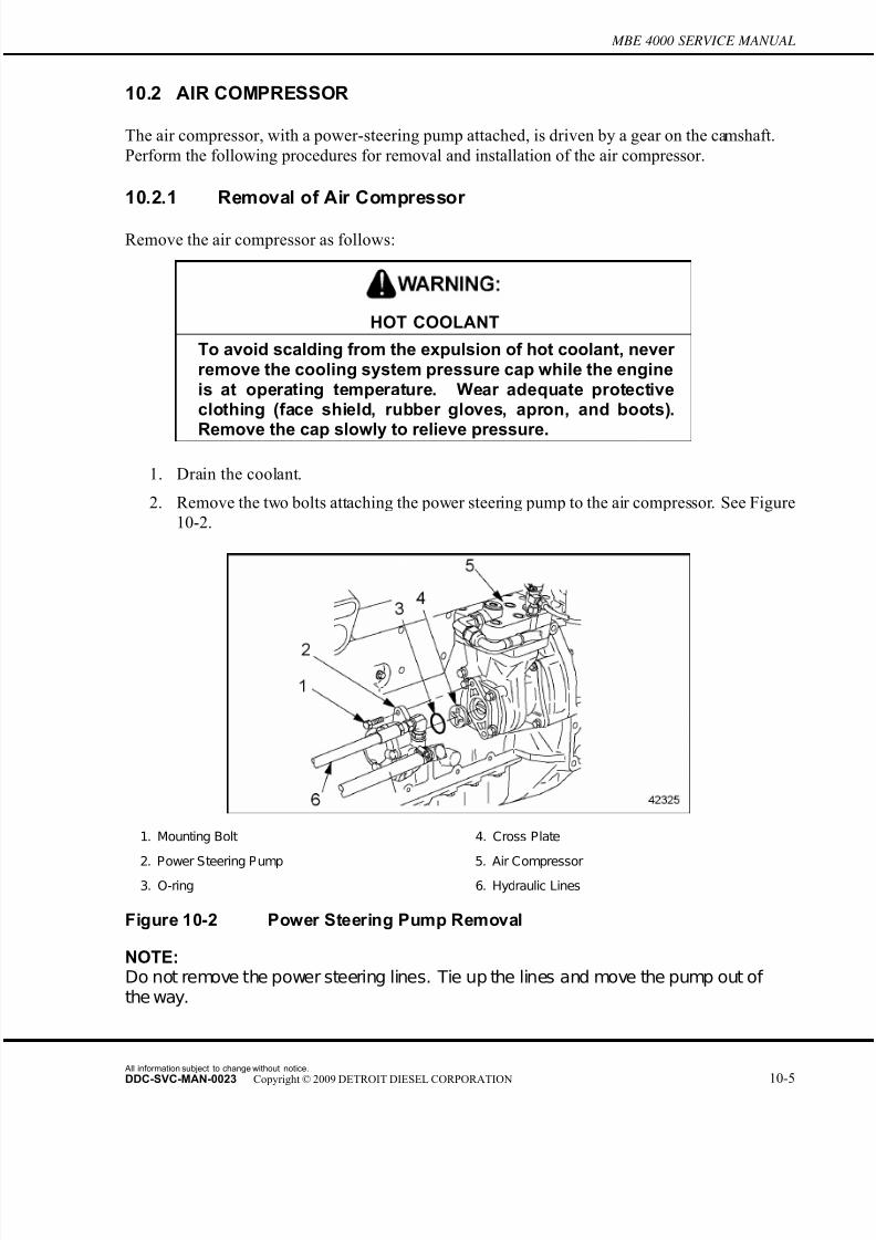
7/22/2019 Manual Mbe 4000 Taller
http://slidepdf.com/reader/full/manual-mbe-4000-taller 521/630
MBE 4000 SERVICE MANUAL
10.2 AIR COMPRESSOR
The air compressor, with a power-steering pump attached, is driven by a gear on the camshaft.
Perform the following procedures for removal and installation of the air compressor.
10.2.1 Removal of Air Compressor
Remove the air compressor as follows:
HOT COOLANT
To avoid scalding from the expulsion of hot coolant, never remove the cooling system pressure cap while the engineis at operating temperature. Wear adequate protectiveclothing (face shield, rubber gloves, apron, and boots).
Remove the cap slowly to relieve pressure.
1. Drain the coolant.
2. Remove the two bolts attaching the power steering pump to the air compressor. See Figure
10-2.
1. Mounting Bolt 4. Cross Plate
2. Power Steering Pump 5. Air Compressor
3. O-ring 6. Hydraulic Lines
Figure 10-2 Power Steering Pump Removal
NOTE:Do not remove the power steering lines. Tie up the lines and move the pump out of the way.
All information subject to change without notice.
DDC-SVC-MAN-0023 Copyright © 2009 DETROIT DIESEL CORPORATION 10-5
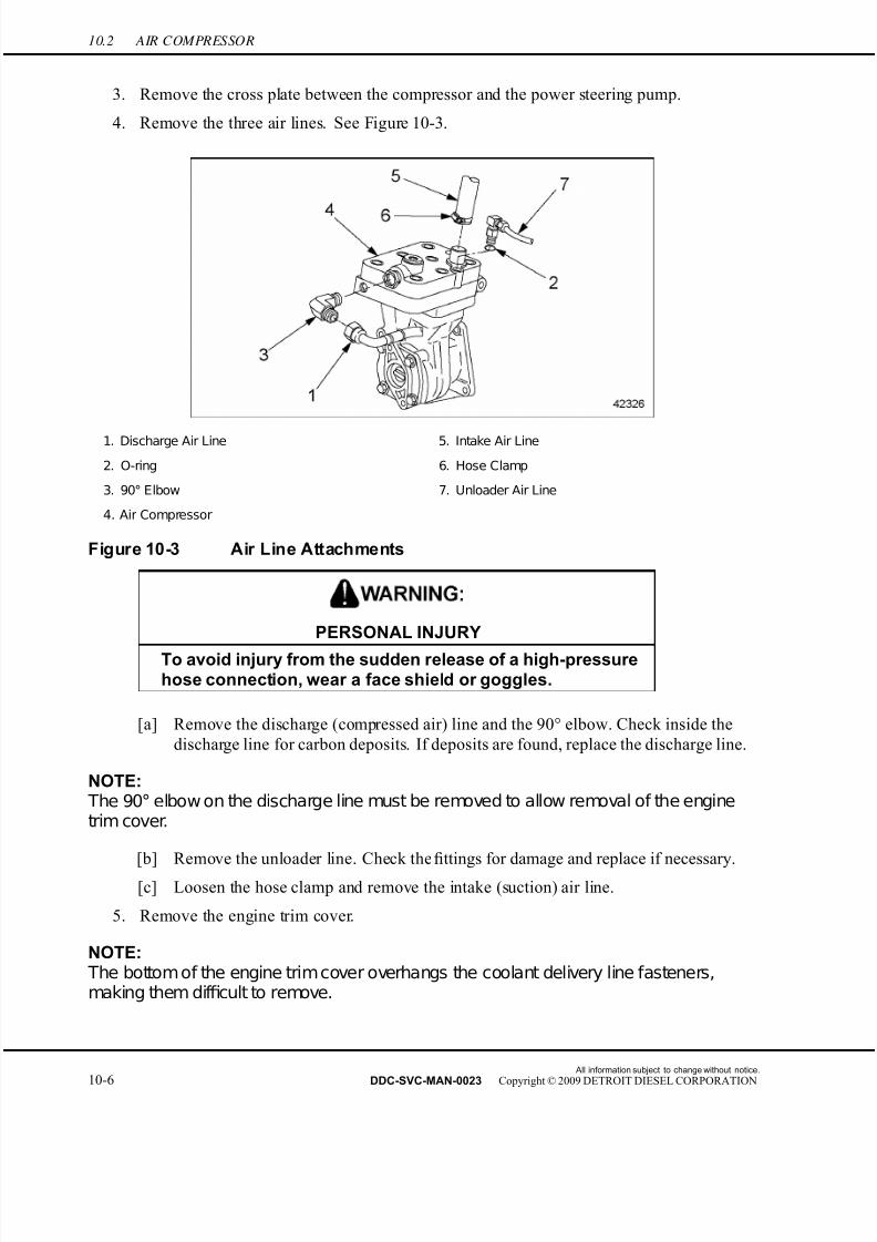
7/22/2019 Manual Mbe 4000 Taller
http://slidepdf.com/reader/full/manual-mbe-4000-taller 522/630
10.2 AIR COMPRESSOR
3. Remove the cross plate between the compressor and the power steering pump.
4. Remove the three air lines. See Figure 10-3.
1. Discharge Air Line 5. Intake Air Line
2. O-ring 6. Hose Clamp
3. 90° Elbow 7. Unloader Air Line
4. Air Compressor
Figure 10-3 Air Line Attachments
PERSONAL INJURY
To avoid injury from the sudden r elease of a high-pressurehose connection, wear a face shield or goggles.
[a] Remove the discharge (compressed air) line and the 90° elbow. Check inside the
discharge line for carbon deposits. If deposits are found, replace the discharge line.
NOTE: The 90° elbow on the discharge line must be removed to allow removal of the enginetrim cover.
[b] Remove the unloader line. Check the fittings for damage and replace if necessary.
[c] Loosen the hose clamp and remove the intake (suction) air line.
5. Remove the engine trim cover.
NOTE: The bottom of the engine trim cover overhangs the coolant delivery line fasteners,making them dif ficult to remove.
All information subject to change without notice.
10-6 DDC-SVC-MAN-0023 Copyright © 2009 DETROIT DIESEL CORPORATION
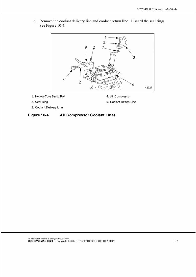
7/22/2019 Manual Mbe 4000 Taller
http://slidepdf.com/reader/full/manual-mbe-4000-taller 523/630
MBE 4000 SERVICE MANUAL
6. Remove the coolant delivery line and coolant return line. Discard the seal rings.
See Figure 10-4.
1. Hollow-Core Banjo Bolt 4. Air Compressor
2. Seal Ring 5. Coolant Return Line
3. Coolant Delivery Line
Figure 10-4 Air Compressor Coolant Lines
All information subject to change without notice.
DDC-SVC-MAN-0023 Copyright © 2009 DETROIT DIESEL CORPORATION 10-7

7/22/2019 Manual Mbe 4000 Taller
http://slidepdf.com/reader/full/manual-mbe-4000-taller 524/630
10.2 AIR COMPRESSOR
7. Remove the four mounting bolts attaching the air compressor to the crankcase. See Figure
10-5.
1. Inboard Upper Mounting Bolt 5. Outboard Upper Mounting Bolt2. Air Compressor 6. Outboard Lower Mounting Bolt
3. Cylinder Block 7. Inboard Lower Mounting Bolt
4. Flywheel Housing
Figure 10-5 Air Compressor Mounting
NOTE: The mounting bolts are of different lengths. The outboard upper mounting bolt isremoved from the rear.
8. Slide the drive gear away from the flywheel. Catch any oil that runs out and disposeof it properly.
10.2.1.1 Air Compressor Inspection
Inspect the air compressor as follows:
1. Inspect the O-rings on the fittings at the air system ports and replace if necessary. If the
O-rings are damaged, re place the fittings also.
2. Replace the O-ring between the power steering pump and the air compressor.
3. Install the locking device (J 46177 or 457 589 03 63 00) on the driveshaft end of the air compressor. This locks the driveshaft to allow removal of the drive nut.
4. Remove the drive gear from the air compressor.
[a] Place the air compressor and locking device (J 46177 or 457 589 03 63 00) in a vise.
Make sure the locking device is tightly secured and cannot slip or slide out of the vise.
[b] Using an impact wrench, remove the drive nut from the drive gear.
All information subject to change without notice.
10-8 DDC-SVC-MAN-0023 Copyright © 2009 DETROIT DIESEL CORPORATION
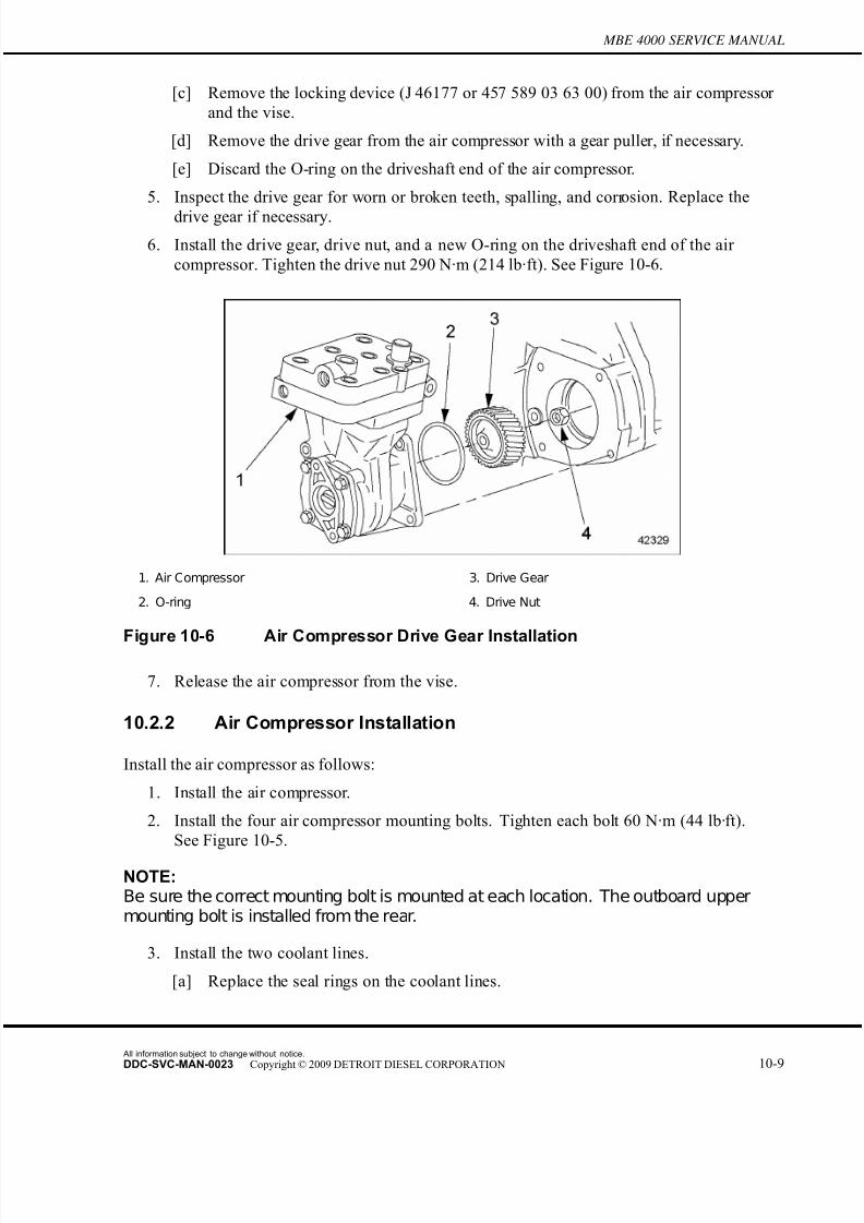
7/22/2019 Manual Mbe 4000 Taller
http://slidepdf.com/reader/full/manual-mbe-4000-taller 525/630
MBE 4000 SERVICE MANUAL
[c] Remove the locking device (J 46177 or 457 589 03 63 00) from the air compressor
and the vise.
[d] Remove the drive gear from the air compressor with a gear puller, if necessary.
[e] Discard the O-ring on the driveshaft end of the air compressor.
5. Inspect the drive gear for worn or broken teeth, spalling, and corr osion. Replace the
drive gear if necessary.
6. Install the drive gear, drive nut, and a new O-ring on the driveshaft end of the air
compressor. Tighten the drive nut 290 N·m (214 lb·ft). See Figure 10-6.
1. Air Compressor 3. Drive Gear
2. O-ring 4. Drive Nut
Figure 10-6 Air Compressor Drive Gear Installation
7. Release the air compressor from the vise.
10.2.2 Air Compressor Installation
Install the air compressor as follows:
1. Install the air com pressor.
2. Install the four air compressor mounting bolts. Tighten each bolt 60 N·m (44 lb·ft).
See Figure 10-5.
NOTE:Be sure the correct mounting bolt is mounted at each location. The outboard uppermounting bolt is installed from the rear.
3. Install the two coolant lines.
[a] Replace the seal rings on the coolant lines.
All information subject to change without notice.
DDC-SVC-MAN-0023 Copyright © 2009 DETROIT DIESEL CORPORATION 10-9

7/22/2019 Manual Mbe 4000 Taller
http://slidepdf.com/reader/full/manual-mbe-4000-taller 526/630
10.2 AIR COMPRESSOR
[b] Install the coolant delivery line at the rear of the air compressor. Tighten the
hollow-core banjo bolt 30 N·m (22 lb·ft).
[c] Install the coolant return line at the front of the air compressor. Tighten the
hollow-core banjo bolt 30 N·m (22 lb·ft).
4. Install the engine trim cover.
5. Install the three air lines. See Figure 10-3.
[a] Install the discharge line and the 90° elbow. Make sure the O-ring is properly
installed on the fitting.
[b] Install the uploader line. Make sure the O-ring is properly installed on the fitting.
[c] Tighten the fittings 80 N·m (60 lb·ft).
[d] Install the intake air line and tighten the hose clamp.
6. Install the cross plate. Use grease to hold it in place while installing the power steering
pump.
7. Install the two bolts attaching the power steering pump to the air compressor. Tighten the bolts 40 N·m (30 lb·ft).
8. Fill the radiator with coolant.
All information subject to change without notice.
10-10 DDC-SVC-MAN-0023 Copyright © 2009 DETROIT DIESEL CORPORATION

7/22/2019 Manual Mbe 4000 Taller
http://slidepdf.com/reader/full/manual-mbe-4000-taller 527/630
MBE 4000 SERVICE MANUAL
10.A ADDITIONAL INFORMATION
Description Page
SP ECIFICATIONS ............................................................................................. 10-11Air Compressor .............................................................................................. 10-11
SPECIFICATIONS
This section contains the specifications for servicing the engine.
Air Compressor
The torque values for the air compressor are listed in Table 10-1. The air governor torque values
are listed in Table 10-2. Listed in Table 10-3 are the approved pipe thread sealants.
Description N·m (lb·ft)
Air Compressor Mounting Bolts 60 (44)
Discharge Line Fitting 80 (60)
Coolant Line Banjo Bolts 30 (22)
Drive Nut 290 (214)
Power Steering Pump Mounting Bolts 40 (30)
Table 10-1 Air Compressor Torque Values
Description N·m (lb·ft)
Air Governor Mounting Bolt, M8 25 (18)
Table 10-2 Air Governor Torque Values
Protectant Material Approved Brand
Loctite® 567
Henkel® 790 PipegripPipe Thread Sealant
(49-00094-108)
Perma-Lok® LH-150
Table 10-3 Approved Pipe Thread Sealants
All information subject to change without notice.
DDC-SVC-MAN-0023 Copyright © 2009 DETROIT DIESEL CORPORATION 10-11

7/22/2019 Manual Mbe 4000 Taller
http://slidepdf.com/reader/full/manual-mbe-4000-taller 528/630
All information subject to change without notice.
10-12 DDC-SVC-MAN-0023 Copyright © 2009 DETROIT DIESEL CORPORATION

7/22/2019 Manual Mbe 4000 Taller
http://slidepdf.com/reader/full/manual-mbe-4000-taller 529/630
11 OPERATION AND VERIFICATION
Section Page
11.1 PREPARATION FOR A FIRST TIME START ........................................... 11-3
11.2 STARTING THE ENGINE ........................................................................ 11-8
11.3 RUNNING THE ENGINE ......................................................................... 11-11
11.4 STOPPING THE ENGINE ........................................................................ 11-13

7/22/2019 Manual Mbe 4000 Taller
http://slidepdf.com/reader/full/manual-mbe-4000-taller 530/630
All information subject to change without notice.
11-2 DDC-SVC-MAN-0023 Copyright © 2009 DETROIT DIESEL CORPORATION
7/22/2019 Manual Mbe 4000 Taller
http://slidepdf.com/reader/full/manual-mbe-4000-taller 531/630
MBE 4000 SERVICE MANUAL
11.1 PREPARATION FOR A FIRST TIME START
NOTE:Before starting the engine, do all the recommended pretrip inspections and dailymaintenance. Check the engine oil and fuel levels, and drain contaminants from thefuel/water separator (optional).
NOTE:If you drain the fuel/water separator completely, you may have to prime the fuel system.
Read the appropriate chapters in the driver's manual for detailed infor mation on instruments,
gauges, and controls. Be sure you are familiar with all of the instruments, gauges and controls
which are needed to operate the engine.
Note especially the location and function of the following:
□ Oil pressure gauge
□ Low oil pressure warning light
□ Coolant temperature gauge
□ High coolant temperature warning light
□ Water in fuel warning light
□ Tachometer
□ Air restriction indicator
When you start the engine, and while you are driving, watch for any signs of engine problems.
If the engine overheats, uses excessive fuel or lubricating oil, vibrates, misfires, makes unusual
noises, or shows an unusual loss of power, turn the engine off as soon as possible and determine
the cause of the problem. Frequently, engine damage may be avoided by a quick response to
early indications of problems.
11.1.1 Checking the Batteries
Use only batteries that have been correctly filled and serviced. To provide corrosion protection,
apply pumpable dielectric grease, part number 48-02349-000, liberally to the terminal pads.
Approved suppliers are listed in Table 11-1.
Manufacturer Lubricant or Part Number
Shell Oil Co. No. 71032; No. 71306
Texaco, Inc. No. 955
Quaker State No. NYK-77
Table 11-1 Approved Electrical Lubricants
11.1.2 Checking the Oil Level
Check the oil level as follows:
All information subject to change without notice.
DDC-SVC-MAN-0023 Copyright © 2009 DETROIT DIESEL CORPORATION 11-3
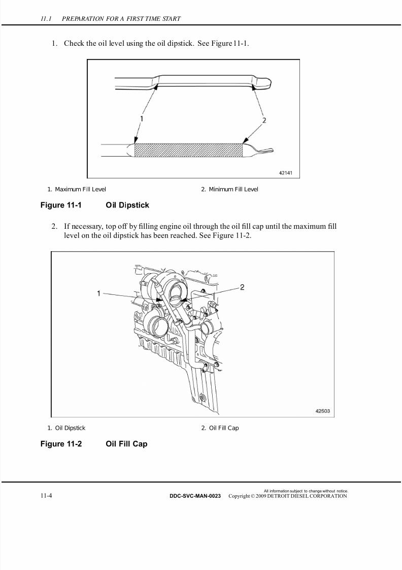
7/22/2019 Manual Mbe 4000 Taller
http://slidepdf.com/reader/full/manual-mbe-4000-taller 532/630
11.1 PREPARATION FOR A FIRST TIME START
1. Check the oil level using the oil dipstick. See Figure 11-1.
1. Maximum Fill Level 2. Minimum Fill Level
Figure 11-1 Oil Dipstick
2. If necessary, top off by filling engine oil through the oil fill cap until the maximum fill
level on the oil dipstick has been reached. See Figure 11-2.
1. Oil Dipstick 2. Oil Fill Cap
Figure 11-2 Oil Fill Cap
All information subject to change without notice.
11-4 DDC-SVC-MAN-0023 Copyright © 2009 DETROIT DIESEL CORPORATION
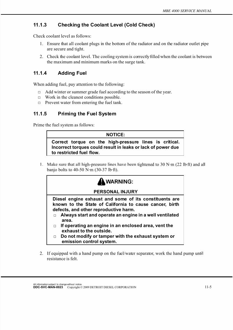
7/22/2019 Manual Mbe 4000 Taller
http://slidepdf.com/reader/full/manual-mbe-4000-taller 533/630
MBE 4000 SERVICE MANUAL
11.1.3 Checking the Coolant Level (Cold Check)
Check coolant level as follows:
1. Ensure that all coolant plugs in the bottom of the radiator and on the radiator outlet pipe
are secure and tight.
2. Check the coolant level. The cooling system is correctly filled when the coolant is betweenthe maximum and minimum marks on the surge tank.
11.1.4 Adding Fuel
When adding fuel, pay attention to the following:
□ Add winter or summer grade fuel according to the season of the year.
□ Work in the cleanest conditions possible.
□ Prevent water from entering the fuel tank.
11.1.5 Priming the Fuel System
Prime the fuel system as follows:
NOTICE:
Correct torque on the high-pressure lines is critical.Incorrect torques could result in leaks or lack of power dueto restricted fuel flow.
1. Make sure that all high-pressure lines have been tightened to 30 N·m (22 lb·ft) and all
banjo bolts to 40-50 N·m (30-37 lb·ft).
PERSONAL INJURY
Diesel engine exhaust and some of its constituents areknown to the State of California to cause cancer, birthdefects, and other reproductive harm.□ Always start and operate an engine in a well ventilated
area.□ If operating an engine in an enclosed area, vent the
exhaust to the outside.□ Do not modify or tamper with the exhaust system or
emission control system.
2. If equipped with a hand pump on the fuel/water separator, work the hand pump until
resistance is felt.
All information subject to change without notice.
DDC-SVC-MAN-0023 Copyright © 2009 DETROIT DIESEL CORPORATION 11-5

7/22/2019 Manual Mbe 4000 Taller
http://slidepdf.com/reader/full/manual-mbe-4000-taller 534/630
11.1 PREPARATION FOR A FIRST TIME START
3. Crank the engine for 30 seconds at a time, but no longer . Before cranking the engine
again, wait at least two minutes. The engine should start within two 30-second atte mpts.
If the engine does not start after the two attempts repeat step 2 and step 3.
4. If the engine does not start after three complete attempts go to step 5.
5. Use the diesel fuel system primer (J-47912) to prime the fuel system. See Figure 11-3.
NOTE: There should be a strong resistance in the hand pump caused by the pressure build-upwithin the fuel system.
NOTE:DDC does not recommend opening the high-pressure lines and bleeding the air fromthe fuel system while cranking.
Figure 11-3 Diesel Fuel System Primer Tool J-47912
6. Fill the fuel system primer three-fourths full with fuel oil.
All information subject to change without notice.
11-6 DDC-SVC-MAN-0023 Copyright © 2009 DETROIT DIESEL CORPORATION

7/22/2019 Manual Mbe 4000 Taller
http://slidepdf.com/reader/full/manual-mbe-4000-taller 535/630
MBE 4000 SERVICE MANUAL
7. Remove the dust cover from the priming valve and connect the line from the primer
tank to the priming valve on the secondary fuel filter. Close the valve on the priming
line. See Figure 11-4.
1. Dust Cap 4. Secondary Fuel Filter
2. Valve 5. Fuel Delivery Line
3. Priming Nipple Valve
Figure 11-4 Priming the Fuel Filter
8. Pump the primer tank numerous times to build up pressure.
9. Open the valve on the priming line and wait 60 seconds for system to fill.
10. Crank the engine for 30 seconds at a time, but no longer . Before cranking the engine
again, wait at least two minutes. The engine should start within four 30-second attempts.
11. Once the engine starts and runs smoothly, close the valve and disconnect the priming
line from the priming nipple valve on the secondary fuel filter. Install the dust cap on
the priming nipple valve.
12. Slowly release the pressure on the diesel fuel system primer (J-47912) by slightly turning
the pumping handle counter-clockwise.
13. With the engine running, check the fuel filter for leaks. Repair any leaks found.
14. Shut down the engine.
All information subject to change without notice.
DDC-SVC-MAN-0023 Copyright © 2009 DETROIT DIESEL CORPORATION 11-7
7/22/2019 Manual Mbe 4000 Taller
http://slidepdf.com/reader/full/manual-mbe-4000-taller 536/630
11.2 STARTING THE ENGINE
11.2 STARTING THE ENGINE
Before operating the engine, do the work described under "Preparation for a First Time Start."
Start the engine as follows:
NOTICE:
Never attempt to start any Mercedes-Benz electronic engineusing ether or any other starting fluid. Serious engine damagecould result.
NOTE:As a safety function, the electronic engine control system allows the engine to start onlyif the transmission is in neutral.
PERSONAL INJURYTo avoid injury when working near or on an operatingengine, remove loose items of clothing and jewelry. Tieback or contain long hair that could be caught in anymoving part causing injury.
1. Turn on the ignition switch.
2. With the accelerator pedal in the idle position, start the engine.
3. Check the engine for leaks.
[a] Check all hoses, hose clamps, and pipe unions on the engine for tightness. Shut downthe engine and tighten them if necessary.
[b] Check the oil feed and return lines at the turbocharger for tightness. Shut down
the engine and tighten them if necessary.
4. Shut down the engine.
5. Approximately five minutes after shutdown, check the engine oil level. If necessary, add
oil up to the maximum fill level on the oil dipstick.
6. Check all the mounting fasteners on the engine for tightness.
11.2.1 Checking the Coolant Level (Hot Check)
Check the coolant levels as follows:
1. Allow the engine to run for approximately five minutes at a moderate speed.
All information subject to change without notice.
11-8 DDC-SVC-MAN-0023 Copyright © 2009 DETROIT DIESEL CORPORATION
7/22/2019 Manual Mbe 4000 Taller
http://slidepdf.com/reader/full/manual-mbe-4000-taller 537/630
MBE 4000 SERVICE MANUAL
HOT COOLANT
To avoid scalding from the expulsion of hot coolant, never remove the cooling system pressure cap while the engine
is at operating temperature. Wear adequate protectiveclothing (face shield, rubber gloves, apron, and boots).Remove the cap slowly to relieve pressure.
2. Then, with the coolant temperature above 50°C (122°F), recheck the coolant level.
3. Add more coolant if necessary. Open the heater valves before adding coolant.
4. Do not close the heater valves until the engine has been run briefly and the coolant level
again checked and corrected as necessary.
11.2.2 Starting an Engine That Has Not Been Run for a Long Time
Before starting an engine which has not been run for a long time, certain special work must
be carried out.
NOTE:At outside temperatures below –20°C (– 4°F) , a coolant preheater is recommended.
PERSONAL INJURY
To avoid injury before starting and running the engine,ensure the vehicle is parked on a level surface, parkingbrake is set, and the wheels are blocked.
1. Chock the tires, place the transmission in neutral, and set the parking brake.
2. Turn on the ignition switch and start the engine
All information subject to change without notice.
DDC-SVC-MAN-0023 Copyright © 2009 DETROIT DIESEL CORPORATION 11-9
7/22/2019 Manual Mbe 4000 Taller
http://slidepdf.com/reader/full/manual-mbe-4000-taller 538/630
11.2 STARTING THE ENGINE
PERSONAL INJURY
Diesel engine exhaust and some of its constituents areknown to the State of California to cause cancer, birth
defects, and other reproductive harm.□ Always start and operate an engine in a well ventilated
area.□ If operating an engine in an enclosed area, vent the
exhaust to the outside.□ Do not modify or tamper with the exhaust system or
emission control system.
3. If the engine doesn't start after 20 seconds, stop. Try again after waiting about one minute.
NOTICE:
Do not rev the engine if the oil pressure gauge indicates no oilpressure. To avoid engine damage, shut down the engine if nooil pressure appears within approximately ten seconds. Checkto determine the cause of the problem.
4. Monitor the oil pressure gauge immediately after starting the engine.
NOTE:Do not place the engine under full load until it reaches operating temperature.
All information subject to change without notice.
11-10 DDC-SVC-MAN-0023 Copyright © 2009 DETROIT DIESEL CORPORATION
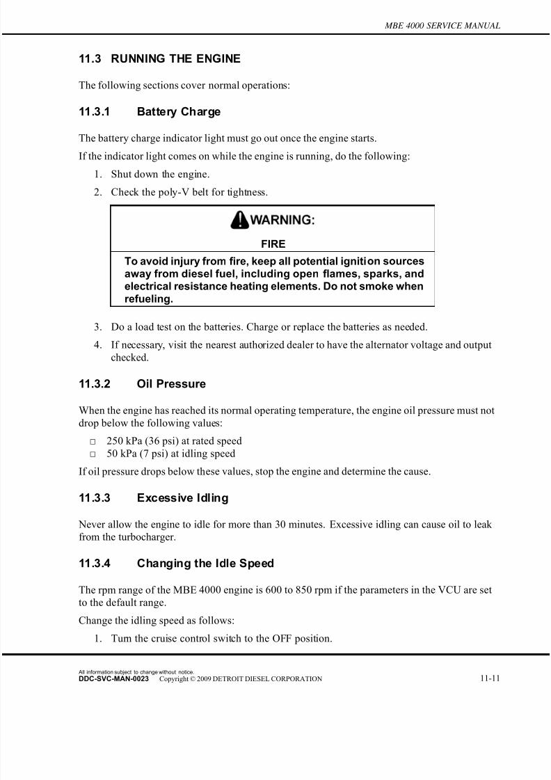
7/22/2019 Manual Mbe 4000 Taller
http://slidepdf.com/reader/full/manual-mbe-4000-taller 539/630
MBE 4000 SERVICE MANUAL
11.3 RUNNING THE ENGINE
The following sections cover normal operations:
11.3.1 Battery Charge
The battery charge indicator light must go out once the engine starts.
If the indicator light comes on while the engine is running, do the following:
1. Shut down the engine.
2. Check the poly-V belt for tightness.
FIRE
To avoid injury from fire, keep all potential ignition sources
away from diesel fuel, including open flames, sparks, andelectrical resistance heating elements. Do not smoke whenrefueling.
3. Do a load test on the batteries. Charge or replace the batteries as needed.
4. If necessary, visit the nearest authorized dealer to have the alternator voltage and output
checked.
11.3.2 Oil Pressure
When the engine has reached its normal operating temperature, the engine oil pressure must notdrop below the following values:
□ 250 kPa (36 psi) at rated speed
□ 50 kPa (7 psi) at idling speed
If oil pressure drops below these values, stop the engine and determine the cause.
11.3.3 Excessive Idling
Never allow the engine to idle for more than 30 minutes. Excessive idling can cause oil to leak
from the turbocharger.
11.3.4 Changing the Idle Speed
The rpm range of the MBE 4000 engine is 600 to 850 rpm if the parameters in the VCU are set
to the default range.
Change the idling speed as follows:
1. Turn the cruise control switch to the OFF position.
All information subject to change without notice.
DDC-SVC-MAN-0023 Copyright © 2009 DETROIT DIESEL CORPORATION 11-11
7/22/2019 Manual Mbe 4000 Taller
http://slidepdf.com/reader/full/manual-mbe-4000-taller 540/630
11.3 RUNNING THE ENGINE
2. To increase the idle speed, push the "Resume" switch until the idle is fast enough.
3. To decrease the idle speed, push the "Decel" switch until the idle is slow enough.
11.3.5 Emergency Running Mode
The engine is equipped with the electronic engine control system, which monitors the engine
as it is running.
As soon as a fault is detected, it is evaluated and one of the followin g measures is initiated.
NOTICE:
To prevent possible serious engine damage, have any faultscorrected without delay by an authorized dealer.
□ In conjunction with the instrumentation control unit (ICU), the code for the electronic
control unit reporting the fault can be read immediately on the display.
□ Complete fault codes are transmitted and can be read using minidiag2 at any authorized
dealer.
□ If the fault is serious enough to impair normal operation, the electronic engine system
switches over to emergency running mode. When in emergency running mode, the engine
operates at a constant 1300 rpm. This allows you to move the vehicle to a service location.
All information subject to change without notice.
11-12 DDC-SVC-MAN-0023 Copyright © 2009 DETROIT DIESEL CORPORATION
7/22/2019 Manual Mbe 4000 Taller
http://slidepdf.com/reader/full/manual-mbe-4000-taller 541/630
MBE 4000 SERVICE MANUAL
11.4 STOPPING THE ENGINE
If the engine has been running at full output or the coolant temperature has been high , allow the
engine to idle for one to two minutes without load.
Then turn off the ignition keyswitch.
If any the following occur, shut down the engine immediately.□ The oil pressure swings back and forth or falls sharply.
□ Engine power and rpm fall, even though the accelerator pedal remains steady.
□ The exhaust pipe gives off heavy smoke.
□ The coolant and/or oil temperature climb abnormally.
□ Abnormal sounds suddenly occur in the engine or turbocharger.
11.4.1 Shutting Down After Hard Operation
After hard operation, do the following:
NOTICE:
After hard operation, allow the engine to idle for one to twominutes without load. Shutting down the engine without idlingmay cause damage to the turbocharger.
1. If the engine has been running at full output or the coolant temperature has been high,
allow the engine to idle for one to two minutes without load.
2. Turn off the ignition switch and shut down the engine.
All information subject to change without notice.
DDC-SVC-MAN-0023 Copyright © 2009 DETROIT DIESEL CORPORATION 11-13

7/22/2019 Manual Mbe 4000 Taller
http://slidepdf.com/reader/full/manual-mbe-4000-taller 542/630
11.4 STOPPING THE ENGINE
All information subject to change without notice.
11-14 DDC-SVC-MAN-0023 Copyright © 2009 DETROIT DIESEL CORPORATION

7/22/2019 Manual Mbe 4000 Taller
http://slidepdf.com/reader/full/manual-mbe-4000-taller 543/630

7/22/2019 Manual Mbe 4000 Taller
http://slidepdf.com/reader/full/manual-mbe-4000-taller 544/630
All information subject to change without notice.
12-2 DDC-SVC-MAN-0023 Copyright © 2009 DETROIT DIESEL CORPORATION

7/22/2019 Manual Mbe 4000 Taller
http://slidepdf.com/reader/full/manual-mbe-4000-taller 545/630
MBE 4000 SERVICE MANUAL
12.1 VALVE LASH CHECKING
Check and adjust the valve lash as follows:
NOTE:Adjust the valve lash when the engine is cold. Wait at least 30 minutes after shutdown,
even if the engine ran only a short time.
Select a method for adjusting the valves. There are two acceptable methods for adjusting the
valves, prior to checking the valve lash:
□ In order, according to the timing sequence used for fuel injection (see Method One—Adjust
Each Cylinder in Firing Order);
□ By type of valve, depending on crankshaft position (see Method Two—Adjust All Valves
Using Two Crankshaft Positions).See Figure 12-1 for the cylinder and valve layout on
MBE 4000 engines.
Figure 12-1 Cylinder and Valve Layout
All information subject to change without notice.
DDC-SVC-MAN-0023 Copyright © 2009 DETROIT DIESEL CORPORATION 12-3
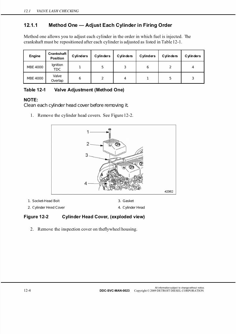
7/22/2019 Manual Mbe 4000 Taller
http://slidepdf.com/reader/full/manual-mbe-4000-taller 546/630
12.1 VALVE LASH CHECKING
12.1.1 Method One — Adjust Each Cylinder in Firing Order
Method one allows you to adjust each cylinder in the order in which fuel is injected. The
crankshaft must be repositioned after each cylinder is adjusted as listed in Table 12-1.
EngineCrankshaft
PositionCylinders Cylinders Cylinders Cylinders Cylinders Cylinders
MBE 4000Ignition
TDC1 5 3 6 2 4
MBE 4000Valve
Overlap6 2 4 1 5 3
Table 12-1 Valve Adjustment (Method One)
NOTE:Clean each cylinder head cover before removing it.
1. Remove the cylinder head covers. See Figure 12-2.
1. Socket-Head Bolt 3. Gasket
2. Cylinder Head Cover 4. Cylinder Head
Figure 12-2 Cylinder Head Cover, (exploded view)
2. Remove the inspection cover on theflywheel housing.
All information subject to change without notice.
12-4 DDC-SVC-MAN-0023 Copyright © 2009 DETROIT DIESEL CORPORATION
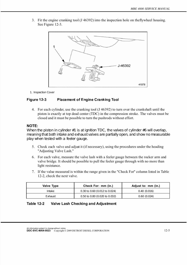
7/22/2019 Manual Mbe 4000 Taller
http://slidepdf.com/reader/full/manual-mbe-4000-taller 547/630
MBE 4000 SERVICE MANUAL
3. Fit the engine cranking tool (J 46392) into the inspection hole on the flywheel housing.
See Figure 12-3.
1. Inspection Cover
Figure 12-3 Placement of Engine Cranking Tool
4. For each cylinder, use the cranking tool (J 46392) to turn over the crankshaft until the
piston is exactly at top dead center (TDC) in the compression stroke. The valves must be
closed and it must be possible to turn the pushrods without effort.
NOTE:When the piston in cylinder #1 is at ignition TDC, the valves of cylinder #6 will overlap,meaning that both intake and exhaustvalves are partially open, and show no measurable
play when tested with a feeler gauge.
5. Check each valve and adjust it (if necessary), using the procedures under the heading
"Adjusting Valve Lash."
6. For each valve, measure the valve lash with a feeler gauge between the rocker arm and
valve bridge. It should be possible to pull the feeler gauge through with no more than
light resistance.
7. If the value measured is within the range given in the "Check For" column listed in Table
12-2, check the next valve.
Valve Type Check For: mm (in.) Adjust to: mm (in.)
Intake 0.30 to 0.60 (0.012 to 0.024) 0.40 (0.016)
Exhaust 0.50 to 0.80 (0.020 to 0.032) 0.60 (0.024)
Table 12-2 Valve Lash Checking and Adjustment
All information subject to change without notice.
DDC-SVC-MAN-0023 Copyright © 2009 DETROIT DIESEL CORPORATION 12-5

7/22/2019 Manual Mbe 4000 Taller
http://slidepdf.com/reader/full/manual-mbe-4000-taller 548/630
12.1 VALVE LASH CHECKING
If the value measured is outside the range given in the "Check For" column listed in Table
12-2, adjust the valve lash.
12.1.2 Method Two — Adjust All Valves Using Two Crankshaft Positions
Method two allows you to adjust all the valves using just two crankshaft positions.
NOTE:Clean each cylinder head cover before removing it.
1. Remove the cylinder head covers. See Figure 12-4.
1. Socket-Head Bolt 3. Gasket
2. Cylinder Head Cover 4. Cylinder Head
Figure 12-4 Cylinder Head Cover, (exploded view)
2. Remove the inspection cover on the flywheel housing.
All information subject to change without notice.
12-6 DDC-SVC-MAN-0023 Copyright © 2009 DETROIT DIESEL CORPORATION
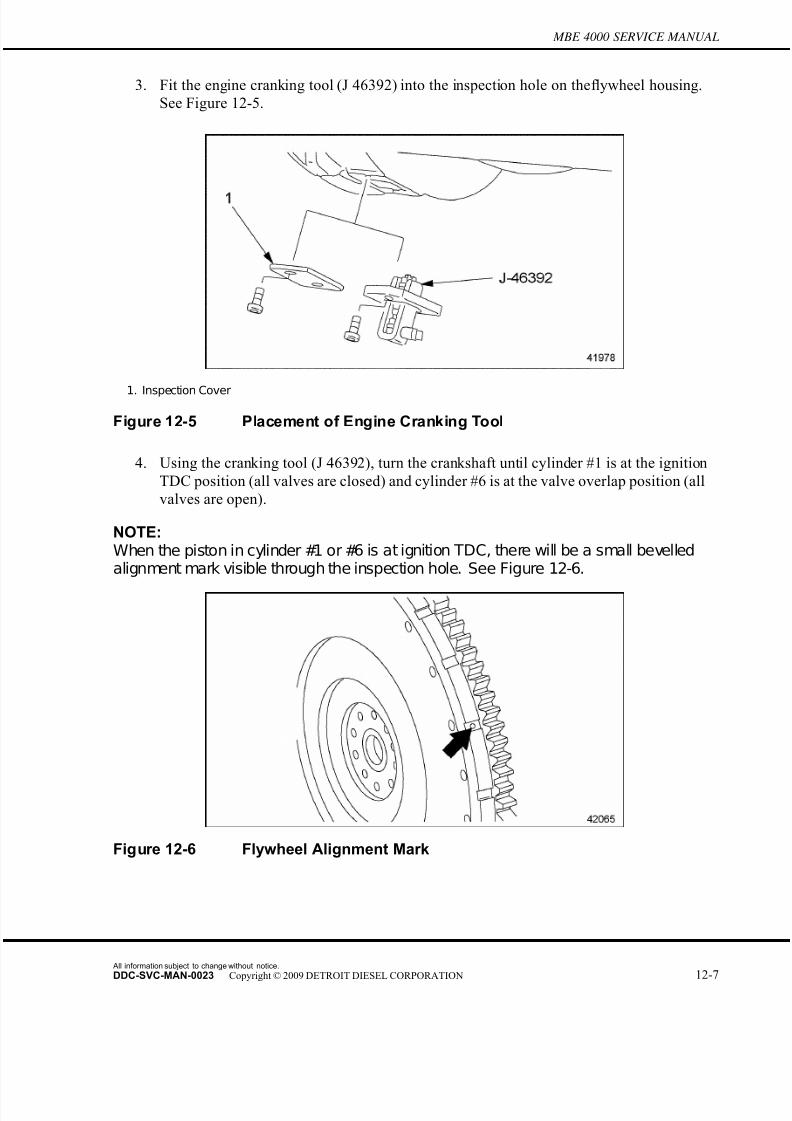
7/22/2019 Manual Mbe 4000 Taller
http://slidepdf.com/reader/full/manual-mbe-4000-taller 549/630
MBE 4000 SERVICE MANUAL
3. Fit the engine cranking tool (J 46392) into the inspection hole on the flywheel housing.
See Figure 12-5.
1. Inspection Cover
Figure 12-5 Placement of Engine Cranking Tool
4. Using the cranking tool (J 46392), turn the crankshaft until cylinder #1 is at the ignition
TDC position (all valves are closed) and cylinder #6 is at the valve overlap position (all
valves are open).
NOTE:When the piston in cylinder #1 or #6 is at ignition TDC, there will be a small bevelledalignment mark visible through the inspection hole. See Figure 12-6.
Figure 12-6 Flywheel Alignment Mark
All information subject to change without notice.
DDC-SVC-MAN-0023 Copyright © 2009 DETROIT DIESEL CORPORATION 12-7

7/22/2019 Manual Mbe 4000 Taller
http://slidepdf.com/reader/full/manual-mbe-4000-taller 550/630
12.1 VALVE LASH CHECKING
5. Check the valves in the "Ignition TDC" row listed in Table 12-3, and adjust them
(if necessary), using the procedures under the headings "Checking Valve Lash" and
"Adjusting Valve Lash."
Engine
Cylinder #1
Crankshaft
Position
Cylinder
Valves/Types*
Cylinder
Valves/Types*
Cylinder
Valves/Types*
Cylinder
Valves/Types*
Cylinder
Valves/Types*
Cylinder
Valves/Types*
1 2 3 4 5 6
MBE 4000Ignition
TDCI/E I E I E —
MBE 4000Valve
Overlap— E I E I I/E
* I=Intake Valve and E= Exhaust Valve
Table 12-3 Valve Adjustment (Method Two)
6. Using the cranking tool (J 46392), turn the crankshaft until cylinder #6 is at the ignition
TDC position (all valves are closed) and cylinder #1 is at the valve overlap position (allvalves are open).
7. Using the same procedure, check the valves in the "Valve Overlap" row listed in Table
12-3and adjust them (if necessary), using the procedures under the headings "Checking
Valve Lash" and "Adjusting Valve Lash."
8. For each valve, measure the valve lash with a feeler gauge between the rocker arm and
valve bridge. It should be possible to pull the feeler gauge through with no more than
light resistance.
9. If the value measured is within the range listed in Table 12-4 in the "Check For" column,
check the next valve.
Valve Type Check For: mm (in.) Adjust to: mm (in.)
Intake 0.30 to 0.60 (0.012 to 0.024) 0.40 (0.016)
Exhaust 0.50 to 0.80 (0.020 to 0.032) 0.60 (0.024)
Table 12-4 Valve Lash Checking and Adjustment
If the value measured is outside the range given in the "Check For" column listed in Table
12-2, adjust the valve lash.
All information subject to change without notice.
12-8 DDC-SVC-MAN-0023 Copyright © 2009 DETROIT DIESEL CORPORATION
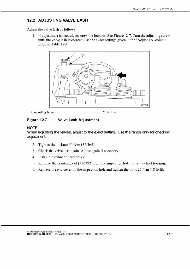
7/22/2019 Manual Mbe 4000 Taller
http://slidepdf.com/reader/full/manual-mbe-4000-taller 551/630
MBE 4000 SERVICE MANUAL
12.2 ADJUSTING VALVE LASH
Adjust the valve lash as follows:
1. If adjustment is needed, unscrew the locknut. See Figure 12-7. Turn the adjusting screw
until the valve lash is correct. Use the exact settings given in the "Adjust To" column
listed in Table 12-4.
1. Adjusting Screw 2. Locknut
Figure 12-7 Valve Lash Adjustment
NOTE:When adjusting the valves, adjust to the exact setting. Use the range only for checkingadjustment.
2. Tighten the locknut 50 N·m (37 lb·ft).
3. Check the valve lash again. Adjust again if necessary.
4. Install the cylinder head covers.
5. Remove the cranking tool (J 46392) from the inspection hole in the flywheel housing.
6. Replace the end cover on the inspection hole and tighten the bolts 25 N·m (18 lb·ft).
All information subject to change without notice.
DDC-SVC-MAN-0023 Copyright © 2009 DETROIT DIESEL CORPORATION 12-9
7/22/2019 Manual Mbe 4000 Taller
http://slidepdf.com/reader/full/manual-mbe-4000-taller 552/630
12.2 ADJUSTING VALVE LASH
All information subject to change without notice.
12-10 DDC-SVC-MAN-0023 Copyright © 2009 DETROIT DIESEL CORPORATION
7/22/2019 Manual Mbe 4000 Taller
http://slidepdf.com/reader/full/manual-mbe-4000-taller 553/630
13 PREVENTIVE MAINTENANCE
Section Page
13.1 SCHEDULED INTERVALS ...................................................................... 13-3

7/22/2019 Manual Mbe 4000 Taller
http://slidepdf.com/reader/full/manual-mbe-4000-taller 554/630
All information subject to change without notice.
13-2 DDC-SVC-MAN-0023 Copyright © 2009 DETROIT DIESEL CORPORATION
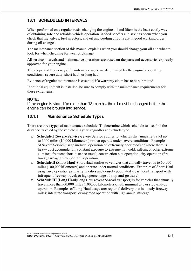
7/22/2019 Manual Mbe 4000 Taller
http://slidepdf.com/reader/full/manual-mbe-4000-taller 555/630
MBE 4000 SERVICE MANUAL
13.1 SCHEDULED INTERVALS
When performed on a regular basis, changing the engine oil and filters is the least costly way
of obtaining safe and reliable vehicle operation. Added benefits and savings occur when you
check that the valves, fuel injectors, and oil and cooling circuits are in good working order
during oil changes.
The maintenance section of this manual explains when you should change your oil and what to
look for when checking for wear or damage.
All service intervals and maintenance operations are based on the parts and accessories expressly
approved for your engine.
The scope and frequency of maintenance work are determined by the engine's operating
conditions: severe duty, short haul, or long haul.
Evidence of regular maintenance is essential if a warranty claim has to be submitted.
If optional equipment is installed, be sure to comply with the maintenance requirements for
these extra items.
NOTE:If the engine is stored for more than 18 months, the oil must be changed before theengine can be brought into service.
13.1.1 Maintenance Schedule Types
There are three types of maintenance schedule. To determine which schedule to use, find the
distance traveled by the vehicle in a year, regardless of vehicle type.
□ Schedule I (Severe Service)Severe Ser vice applies to vehicles that annually travel up
to 6000 miles (10,000 kilometers) or that operate under severe conditions. Examplesof Severe Service usage include: operation on extremely poor roads or where there is
heavy dust accumulation; constant ex posure to extreme hot, cold, salt-air, or other extreme
climates; frequent short-distance travel; construction-site operation; city operation (fire
truck, garbage truck); or farm operation.
□ Schedule II (Short Haul)Short Haul applies to vehicles that annually travel up to 60,000
miles (100,000 kilometers) and operate under normal conditions. Examples of Short-Haul
usage are: operation primarily in cities and densely populated areas; local transport with
infrequent freeway travel; or high percentage of stop-and-go travel.
□ Schedule III (Long Haul)Long Haul (over-the-road transport) is for vehicles that annually
travel more than 60,000 miles (100,000 kilometers), with minimal city or stop-and-go
operation. Examples of Long-Haul usage are: regional delivery that is mostly freewaymiles; interstate transport; or any road operation with high annual mileage.
All information subject to change without notice.
DDC-SVC-MAN-0023 Copyright © 2009 DETROIT DIESEL CORPORATION 13-3

7/22/2019 Manual Mbe 4000 Taller
http://slidepdf.com/reader/full/manual-mbe-4000-taller 556/630
13.1 SCHEDULED INTERVALS
13.1.1.1 Maintenance Schedule and Interval Operations
The three different schedules of vehicle usage (severe, short haul, and long haul) are
listed in Table 13-1. For each schedule, the appropriate distance interval (in miles and kilometers)
is given for performing and repeating each maintenance operation.
Maintenance IntervalsMaintenance
Schedule
Maintenance Interval
Operation Frequency Miles Km
Maintenance 1 (M1) every 10,000 17,000
Optional oil centrifuge
(change rotor)every 20,000 32,000
Maintenance 2 (M2) every 20,000 32,000
first 20,000 32,000
Schedule I (Severe
Service) vehicles that
annually travel up to
6000 miles (10 000 km)
Maintenance 3 (M3)then every 40,000 68,000
Maintenance 1 (M1) every 15,000 25 000
Optional oil centrifuge(change rotor)
every 20,000 32,000
Maintenance 2 (M2) every 30,000 50,000
first 30,000 50 000Maintenance 3 (M3)
then every 60,000 100,000
Schedule II (Short Haul)
vehicles that annually
travel up to 60,000 miles
(100 000 km)
Maintenance 4 (M4) every 120,000 200,000
Optional oil centrifuge
(change rotor)every 20,000 32,000
Maintenance 1 (M1) every 25,000 42,000
Maintenance 2 (M2) every 50,000 84,000
first 50,000 84,000Maintenance 3 (M3)
then every 100,000 167,000
Schedule III (Long
Haul)vehicles that
annually travel more
than 60,000 miles
(100 000 km)
Maintenance 4 (M4) every 200,000 334,000
Table 13-1 Maintenance Schedule Table
The descriptions of all maintenance operations, indicating all maintenance operation sets at which
each operation must be performed are listed in Table 13-2, listed in Table 13-3, listed in Table 13-4.
These three maintenance interval tables show which maintenance operation must be performed at
the actual distances (in miles or kilometers) for each maintenance operation. The schedule of actual distances is based on the intervals given in the Maintenance Schedule Table.
All information subject to change without notice.
13-4 DDC-SVC-MAN-0023 Copyright © 2009 DETROIT DIESEL CORPORATION
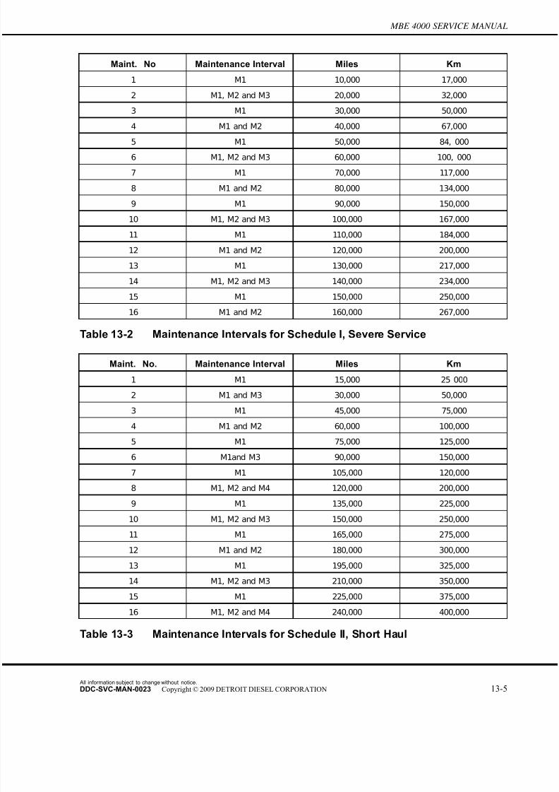
7/22/2019 Manual Mbe 4000 Taller
http://slidepdf.com/reader/full/manual-mbe-4000-taller 557/630
MBE 4000 SERVICE MANUAL
Maint. No Maintenance Interval Miles Km
1 M1 10,000 17,000
2 M1, M2 and M3 20,000 32,000
3 M1 30,000 50,000
4 M1 and M2 40,000 67,000
5 M1 50,000 84, 000
6 M1, M2 and M3 60,000 100, 000
7 M1 70,000 117,000
8 M1 and M2 80,000 134,000
9 M1 90,000 150,000
10 M1, M2 and M3 100,000 167,000
11 M1 110,000 184,000
12 M1 and M2 120,000 200,000
13 M1 130,000 217,000
14 M1, M2 and M3 140,000 234,000
15 M1 150,000 250,000
16 M1 and M2 160,000 267,000
Table 13-2 Maintenance Intervals for Schedule I, Severe Service
Maint. No. Maintenance Interval Miles Km
1 M1 15,000 25 000
2 M1 and M3 30,000 50,000
3 M1 45,000 75,000
4 M1 and M2 60,000 100,000
5 M1 75,000 125,000
6 M1and M3 90,000 150,000
7 M1 105,000 120,000
8 M1, M2 and M4 120,000 200,000
9 M1 135,000 225,000
10 M1, M2 and M3 150,000 250,000
11 M1 165,000 275,000
12 M1 and M2 180,000 300,000
13 M1 195,000 325,000
14 M1, M2 and M3 210,000 350,000
15 M1 225,000 375,000
16 M1, M2 and M4 240,000 400,000
Table 13-3 Maintenance Intervals for Schedule II, Short Haul
All information subject to change without notice.
DDC-SVC-MAN-0023 Copyright © 2009 DETROIT DIESEL CORPORATION 13-5
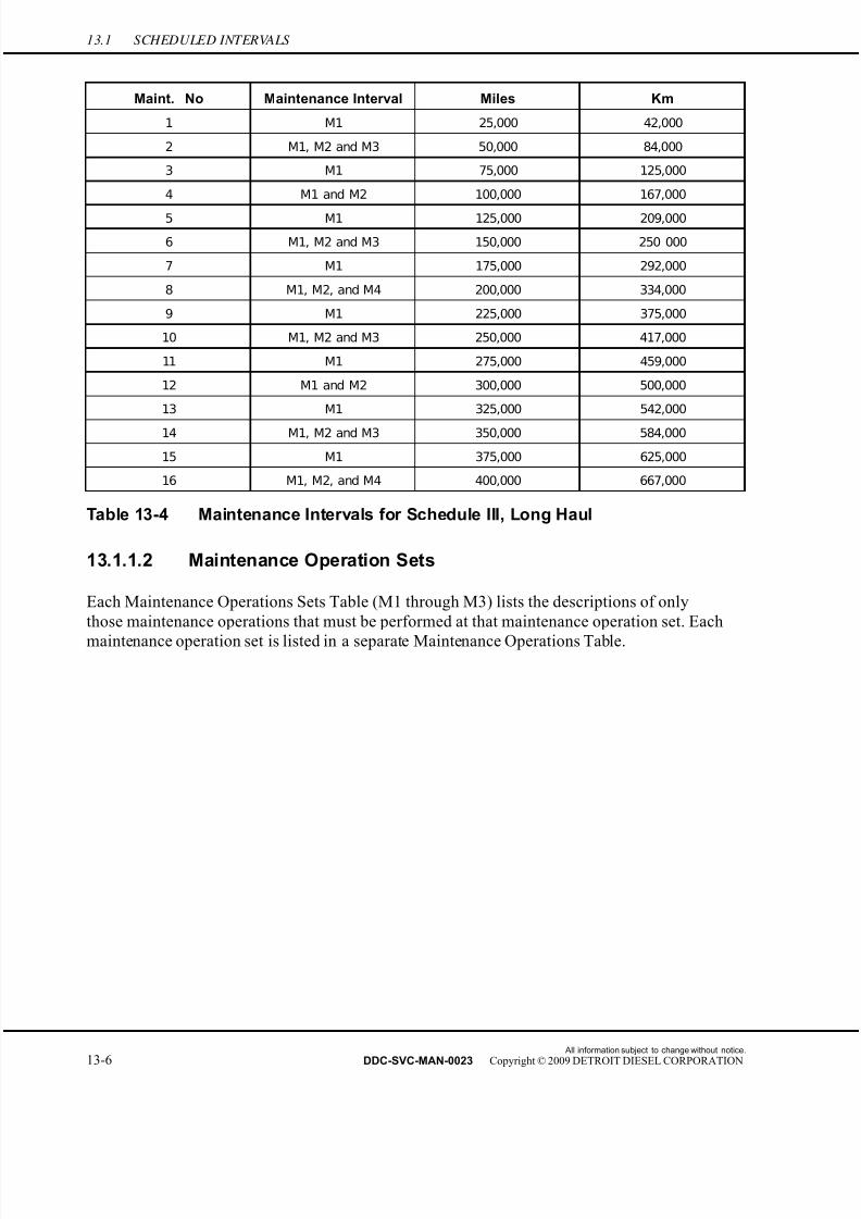
7/22/2019 Manual Mbe 4000 Taller
http://slidepdf.com/reader/full/manual-mbe-4000-taller 558/630
13.1 SCHEDULED INTERVALS
Maint. No Maintenance Interval Miles Km
1 M1 25,000 42,000
2 M1, M2 and M3 50,000 84,000
3 M1 75,000 125,000
4 M1 and M2 100,000 167,000
5 M1 125,000 209,000
6 M1, M2 and M3 150,000 250 000
7 M1 175,000 292,000
8 M1, M2, and M4 200,000 334,000
9 M1 225,000 375,000
10 M1, M2 and M3 250,000 417,000
11 M1 275,000 459,000
12 M1 and M2 300,000 500,000
13 M1 325,000 542,000
14 M1, M2 and M3 350,000 584,000
15 M1 375,000 625,000
16 M1, M2, and M4 400,000 667,000
Table 13-4 Maintenance Intervals for Schedule III, Long Haul
13.1.1.2 Maintenance Operation Sets
Each Maintenance Operations Sets Table (M1 through M3) lists the descriptions of only
those maintenance operations that must be performed at that maintenance operation set. Each
maintenance operation set is listed in a separate Maintenance Operations Table.
All information subject to change without notice.
13-6 DDC-SVC-MAN-0023 Copyright © 2009 DETROIT DIESEL CORPORATION
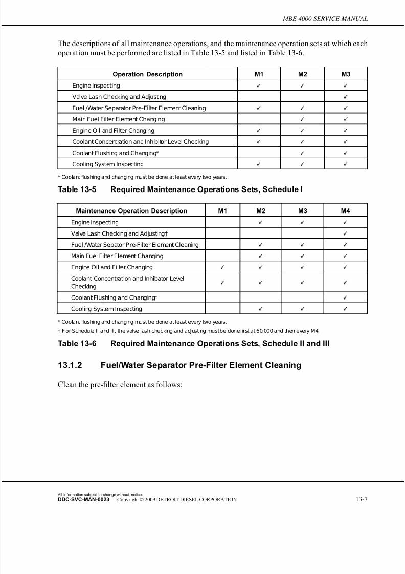
7/22/2019 Manual Mbe 4000 Taller
http://slidepdf.com/reader/full/manual-mbe-4000-taller 559/630
MBE 4000 SERVICE MANUAL
The descriptions of all maintenance operations, and the maintenance operation sets at which each
operation must be performed are listed in Table 13-5 and listed in Table 13-6.
Operation Description M1 M2 M3
Engine Inspecting
Valve Lash Checking and Adjusting
Fuel /Water Separator Pre-Filter Element Cleaning
Main Fuel Filter Element Changing
Engine Oil and Filter Changing
Coolant Concentration and Inhibitor Level Checking
Coolant Flushing and Changing*
Cooling System Inspecting
* Coolant flushing and changing must be done at least every two years.
Table 13-5 Required Maintenance Operations Sets, Schedule I
Maintenance Operation Description M1 M2 M3 M4
Engine Inspecting
Valve Lash Checking and Adjusting†
Fuel /Water Sepator Pre-Filter Element Cleaning
Main Fuel Filter Element Changing
Engine Oil and Filter Changing
Coolant Concentration and Inhibator Level
Checking
Coolant Flushing and Changing*
Cooling System Inspecting
* Coolant flushing and changing must be done at least every two years.
† F or Schedule II and III, the valve lash checking and adjusting mustbe donefirst at 60,000 and then every M4.
Table 13-6 Required Maintenance Operations Sets, Schedule II and III
13.1.2 Fuel/Water Separator Pre-Filter Element Cleaning
Clean the pre-filter element as follows:
All information subject to change without notice.
DDC-SVC-MAN-0023 Copyright © 2009 DETROIT DIESEL CORPORATION 13-7
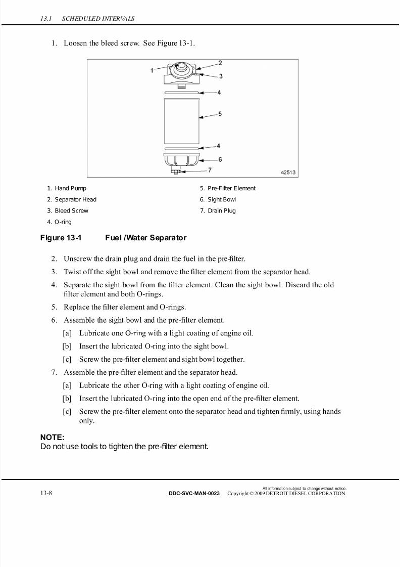
7/22/2019 Manual Mbe 4000 Taller
http://slidepdf.com/reader/full/manual-mbe-4000-taller 560/630
13.1 SCHEDULED INTERVALS
1. Loosen the bleed screw. See Figure 13-1.
1. Hand Pump 5. Pre-Filter Element
2. Separator Head 6. Sight Bowl
3. Bleed Screw 7. Drain Plug
4. O-ring
Figure 13-1 Fuel /Water Separator
2. Unscrew the drain plug and drain the fuel in the pre-filter.
3. Twist off the sight bowl and remove the filter element from the separator head.
4. Separate the sight bowl from the filter element. Clean the sight bowl. Discard the old
fi
lter element and both O-rings.5. Replace the filter element and O-rings.
6. Assemble the sight bowl and the pre-filter element.
[a] Lubricate one O-ring with a light coating of engine oil.
[b] Insert the lubricated O-ring into the sight bowl.
[c] Screw the pre-filter element and sight bowl together.
7. Assemble the pre-filter element and the separator head.
[a] Lubricate the other O-ring with a light coating of engine oil.
[b] Insert the lubricated O-ring into the open end of the pre-filter element.
[c] Screw the pre-filter element onto the separator head and tighten firmly, using hands
only.
NOTE:Do not use tools to tighten the pre-filter element.
All information subject to change without notice.
13-8 DDC-SVC-MAN-0023 Copyright © 2009 DETROIT DIESEL CORPORATION

7/22/2019 Manual Mbe 4000 Taller
http://slidepdf.com/reader/full/manual-mbe-4000-taller 561/630
MBE 4000 SERVICE MANUAL
8. Insert the filter element into the pre-filter housing and screw the cap onto the housing.
Tighten the cap 25 N·m (18 lb·ft).
9. Tighten the drain plug.
10. Bleed the fuel system.
[a] Make sure that all high-pressure lines have been tightened to 25 N·m (18 lb·ft) and all
banjo bolts to 50 N·m (37 lb·ft).
NOTICE:
Correct torque on the high pressure lines is critical. Incorrecttorques could result in leaks or lack of power due to restrictedfuel flow.
[b] If equipped with a hand pump on the fuel/water separator, work the hand pump
50 times.
NOTE: There should be a strong resistance in the hand pump, caused by the pressure build-upwithin the fuel system.
PERSONAL INJURY
Diesel engine exhaust and some of its constituents areknown to the State of California to cause cancer, birthdefects, and other reproductive harm.□ Always start and operate an engine in a well ventilated
area.□ If operating an engine in an enclosed area, vent the
exhaust to the outside.□ Do not modify or tamper with the exhaust system or
emission control system.
[c] Crank the engine for 30 seconds at a time, but no longer. Before cranking the engine
again, wait at least two minutes. The engine should start within four 30 second
attempts.
13.1.3 Main Fuel Filter Element Changing
Change the main fuel filter element as follows:
1. Open the fuel filler cap to release pressure in the fuel system. Replace and tighten the cap.
All information subject to change without notice.
DDC-SVC-MAN-0023 Copyright © 2009 DETROIT DIESEL CORPORATION 13-9

7/22/2019 Manual Mbe 4000 Taller
http://slidepdf.com/reader/full/manual-mbe-4000-taller 562/630
13.1 SCHEDULED INTERVALS
2. Clean the outside of the fuel filter housing. See Figure 13-2.
1. Filter Housing Cap 3. Filter Element
2. O-ring
Figure 13-2 Main Fuel Filter
3. Using a 36-mm socket wrench insert, unscrew the cap on the fuel filter and remove it,
along with the filter element. Pull both the cap and the filter element a short distance out
of the filter housing. Allow the fuel to drain off the filter into the housing.
4. Remove the cap with the filter element. To release the filter element, twist the lower edge
of the filter element to one side.
NOTICE:
To prevent damage to the filter housing, do not allow dirt to getinto the filter housing.
5. Clean the filter housing cap.
6. Replace the O-ring.7. Install the new filter element in the cap. Make sure the filter element is securely in place.
8. Screw on the cap with the filter element. Tighten the cap 25 N·m (18 lb·ft).
9. Bleed the fuel system.
[a] Make sure that all high-pressure lines have been tightened to 25 N·m (18 lb·ft) and all
banjo bolts to 50 N·m (37 lb·ft).
All information subject to change without notice.
13-10 DDC-SVC-MAN-0023 Copyright © 2009 DETROIT DIESEL CORPORATION

7/22/2019 Manual Mbe 4000 Taller
http://slidepdf.com/reader/full/manual-mbe-4000-taller 563/630
MBE 4000 SERVICE MANUAL
NOTICE:
Correct torque on the high pressure lines is critical. Incorrecttorques could result in leaks or lack of power due to restrictedfuel flow.
[b] If equipped with a hand pump on the fuel/water separator, work the hand pump50 times.
NOTE: There should be a strong resistance in the hand pump, caused by the pressure build-upwithin the fuel system.
PERSONAL INJURY
Diesel engine exhaust and some of its constituents are
known to the State of California to cause cancer, birthdefects, and other reproductive harm.□ Always start and operate an engine in a well ventilated
area.□ If operating an engine in an enclosed area, vent the
exhaust to the outside.□ Do not modify or tamper with the exhaust system or
emission control system.
[c] Crank the engine for 30 seconds at a time, but no longer. Wait at least two minutes,
then crank again. The engine should start within four 30-second attempts.
10. Start the engine. Check the fuel filter housing for leaks.
All information subject to change without notice.
DDC-SVC-MAN-0023 Copyright © 2009 DETROIT DIESEL CORPORATION 13-11
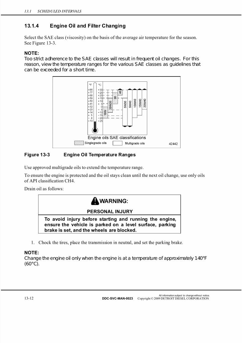
7/22/2019 Manual Mbe 4000 Taller
http://slidepdf.com/reader/full/manual-mbe-4000-taller 564/630
13.1 SCHEDULED INTERVALS
13.1.4 Engine Oil and Filter Changing
Select the SAE class (viscosity) on the basis of the average air temperature for the s eason.
See Figure 13-3.
NOTE:
Too strict adherence to the SAE classes will result in frequent oil changes. For thisreason, view the temperature ranges for the various SAE classes as guidelines thatcan be exceeded for a short time.
Figure 13-3 Engine Oil Temperature Ranges
Use approved multigrade oils to extend the temperature range.
To ensure the engine is protected and the oil stays clean until the next oil change, use only oils
of API classification CH4.
Drain oil as follows:
PERSONAL INJURY
To avoid injury before starting and running the engine,ensure the vehicle is parked on a level surface, parkingbrake is set, and the wheels are blocked.
1. Chock the tires, place the transmission in neutral, and set the parking brake.
NOTE:Change the engine oil only when the engine is at a temperature of approximately 140°F(60°C).
All information subject to change without notice.
13-12 DDC-SVC-MAN-0023 Copyright © 2009 DETROIT DIESEL CORPORATION
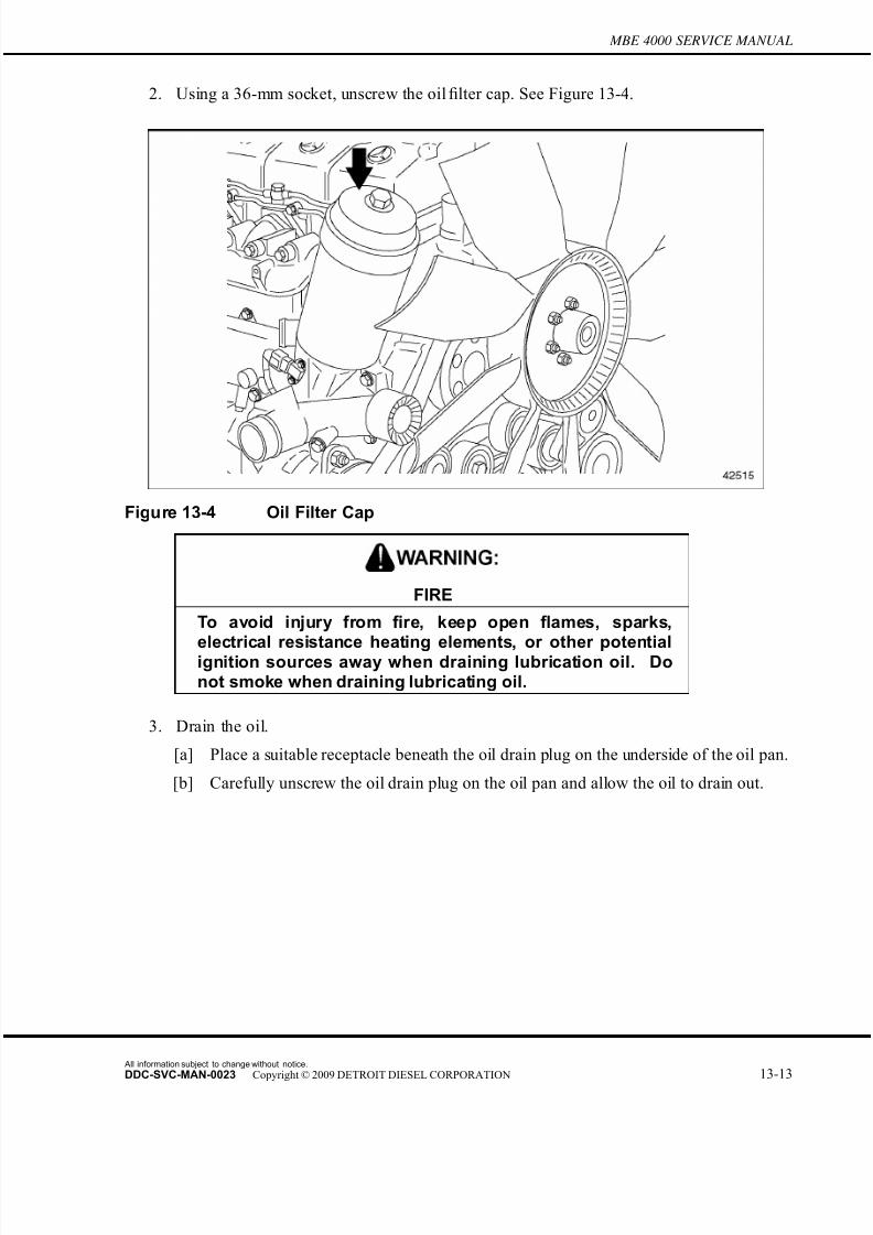
7/22/2019 Manual Mbe 4000 Taller
http://slidepdf.com/reader/full/manual-mbe-4000-taller 565/630
MBE 4000 SERVICE MANUAL
2. Using a 36-mm socket, unscrew the oil filter cap. See Figure 13-4.
Figure 13-4 Oil Filter Cap
FIRE
To avoid injury from fire, keep open flames, sparks,
electrical resistance heating elements, or other potentialignition sources away when draining lubrication oil. Donot smoke when draining lubricating oil.
3. Drain the oil.
[a] Place a suitable receptacle beneath the oil drain plug on the underside of the oil pan.
[b] Carefully unscrew the oil drain plug on the oil pan and allow the oil to drain out.
All information subject to change without notice.
DDC-SVC-MAN-0023 Copyright © 2009 DETROIT DIESEL CORPORATION 13-13
7/22/2019 Manual Mbe 4000 Taller
http://slidepdf.com/reader/full/manual-mbe-4000-taller 566/630
13.1 SCHEDULED INTERVALS
[c] Discard the O-ring on the oil drain plug.
Figure 13-5 Engine Oil Drain Plug
4. Remove both the filter cap and the filter element. To release the filter element, twist the
lower edge of the filter element to the side. See Figure 13-6.
1. Cap 3. Filter Element
2. O-ring
Figure 13-6 Cap with Oil Filter Element
NOTICE:
To prevent damage to the filter housing, ensure that no foreignobjects get inside it. Do not wipe clean thefilter housing.
5. Replace the O-ring on the cap. See Figure 13-6.
6. Install the new filter into the cap. Make sure the filter element is securely in place.
All information subject to change without notice.
13-14 DDC-SVC-MAN-0023 Copyright © 2009 DETROIT DIESEL CORPORATION

7/22/2019 Manual Mbe 4000 Taller
http://slidepdf.com/reader/full/manual-mbe-4000-taller 567/630
MBE 4000 SERVICE MANUAL
7. Screw the cap onto the oil filter housing. Tighten the cap 45 N·m (33 lb·ft).
8. Install the oil drain plug, using a new O-ring. Tighten the plug 80 N·m (60 lb·ft).
9. Add new engine oil through the oil fill, see Figure 13-7, until the maximum fill level on
the oil dipstick has been reached. Engine fill capacity is 44.4 qts (42.0 L).
1. Oil Dipstick 2. Oil Fill Cap
Figure 13-7 Oil Fill
PERSONAL INJURY
Diesel engine exhaust and some of its constituents areknown to the State of California to cause cancer, birthdefects, and other reproductive harm.□ Always start and operate an engine in a well ventilated
area.□ If operating an engine in an enclosed area, vent the
exhaust to the outside.□ Do not modify or tamper with the exhaust system or
emission control system.
10. Start the engine with the accelerator pedal in the idle position. Monitor the oil pressure
gauge.
All information subject to change without notice.
DDC-SVC-MAN-0023 Copyright © 2009 DETROIT DIESEL CORPORATION 13-15
7/22/2019 Manual Mbe 4000 Taller
http://slidepdf.com/reader/full/manual-mbe-4000-taller 568/630
13.1 SCHEDULED INTERVALS
NOTICE:
Keep the engine running at idling speed until an oil pressurereading is obtained. If no oil pressure is shown afterapproximately 10 seconds, stop the engine and determinethe cause. Failure to do so could result in engine damage.
11. Check the filter and oil drain plug for signs of leakage.
12. Stop the engine. Check the oil level again after approximately five minutes. If necessary,
add oil up to the maximum fill level on the oil dipstick.
13.1.5 Coolant Concentration and Inhibitor Level Checking
Check the coolant concentration as follows:
All information subject to change without notice.
13-16 DDC-SVC-MAN-0023 Copyright © 2009 DETROIT DIESEL CORPORATION
7/22/2019 Manual Mbe 4000 Taller
http://slidepdf.com/reader/full/manual-mbe-4000-taller 569/630
7/22/2019 Manual Mbe 4000 Taller
http://slidepdf.com/reader/full/manual-mbe-4000-taller 570/630
13.1 SCHEDULED INTERVALS
Check the nitrite concentration at regular intervals as listed in Table 13-9 with a Power Trac
3–Way Test Strip. Nitrite levels must be within 800–2400 PPM. Additional SCA must be added
to the coolant when it becomes depleted, as indicated by a nitrite concentration of 800 PPM or
less. If the nitrite concentration is greater than 800 PPM, do not add additional SCA. If the nitrite
concentration is above 2400 PPM, the system is over-inhibited and should be pa rtially drained
and filled with a 50/50 mix of water and EG or PG.
NOTE:Drain intervals listed in Table 13-9 are dependent on proper maintenance.
Service Application Inhibitor Test Interval
On-highway Trucks and Motor Coaches 20,000 Miles (32,000 Kilometers)
City Transit Coaches, P ick-up and Delivery Short
Trip, and Emergency Vehicles
6,00 Miles (9,600 Kilometers) or three months,
whichever comes first
Industrial, Continuous Duty Generator Set, and
all Other Applications
500 Hours or three months, whichever comes first
Stand-by Generator Set 200 Hours or yearly, whichever comes first
Table 13-8 Required Coolant Inhibitor Test Intervals
All information subject to change without notice.
13-18 DDC-SVC-MAN-0023 Copyright © 2009 DETROIT DIESEL CORPORATION

7/22/2019 Manual Mbe 4000 Taller
http://slidepdf.com/reader/full/manual-mbe-4000-taller 571/630
MBE 4000 SERVICE MANUAL
Coolant Maintenance Interval Action
A. 20,000 miles (32,000 km)
or 3 months
B. 500 hours or 3 months
Test nitrite concentration with test
strip. Add SCA or dilute coolant as
needed.Antifreeze/Water + SC A
Inhibitor (DDC Power Cool)
A. 30,000 miles (480,000 km)
B. 2 years or 4,000 hours
Drain and clean system. Replace
with new coolant.
A. 20,000 miles (32,000 km)
or 3 months
B. 500 hours or 3 months
Drain and clean system. Replace
with new coolant.Ethylene Glycol/Water +
SCA InhibitorA. 300,000 miles (480,000 km)
B. 2 years or 4,000 hours
Drain and clean system. Replace
with new coolant.
A. 300,000 miles (480,000 km)
or 2 years
B. 5,000 hours
Add Power Cool Plus E xtender
Ethylene Glycol/Water +
NOAT InhibitorA.600,000 miles (960,000 km)
B. 4 years or 10,000 hours
Drain and clean system. Replace
with new coolant.
A. 20,000 miles (32,000 km)
or 3 months
B. 500 hours or 3 months
Drain and clean system. Replace
with new coolant.
Water Only +SCA Inhibitor
A. 3000,000 miles (480,000 km)
B. 2 years or 4,000 hours
Drain and clean system. Replace
with new coolant.
A. 3000,000 miles (480,000 km)
or 2 years
B. 5,000 hours
Add Power Cool Plus E xtender
Water Only +NOAT Inhibitor
A. 6000,000 miles (960,000 km)
B. 4 years or 10,000 hours
Drain and clean system. Replace
with new coolant.
A =On-highway trucks and motor coaches, city transit coaches, pickup and delivery, short trip, and emergency vehicles.
B = Industrial, generator set, and other applications
Table 13-9 Nitrite Interval Checks
13.1.7 Inhibitor Level Checking
Use Detroit Diesel PowerTrac 3–way Coolant Test Strips to measure nitrite and glycol
concentrations. Cavitation/corrosion protection is indicated on the strip by the level of nitrite
concentration. Freeze/boil-over protection is determined by glycol concentration.
Check the inhibitor level as follows:
All information subject to change without notice.
DDC-SVC-MAN-0023 Copyright © 2009 DETROIT DIESEL CORPORATION 13-19

7/22/2019 Manual Mbe 4000 Taller
http://slidepdf.com/reader/full/manual-mbe-4000-taller 572/630
13.1 SCHEDULED INTERVALS
HOT COOLANT
To avoid scalding from the expulsion of hot coolant, never remove the cooling system pressure cap while the engine
is at operating temperature. Wear adequate protectiveclothing (face shield, rubber gloves, apron, and boots).Remove the cap slowly to relieve pressure.
1. Dip the test strip into the coolant for one second, then remove it. Shake the strip vigorously
to remove excess liquid.
2. Immediately compare the end pad to the color chart on the container to determine the
glycol concentration.
3. Sixty seconds (one minute) after dipping, compare the nitrite pad to the color chart on the
container to determine the nitrite concentration.
4. If the additive indicator (middle pad) shows any color change, this indicates the presence
of an unauthorized inhibitor.
5. If any problems exist, change the coolant.
6. After each use, replace and tighten the cap on the test strip container. Discard any test
strips that have turned light pink or tan in color.
7. Close and tighten the cap on the surge tank.
13.1.8 Coolant Flushing and Changing
Flush and change the coolant as follows:
HOT COOLANT
To avoid scalding from the expulsion of hot coolant, never remove the cooling system pressure cap while the engineis at operating temperature. Wear adequate protectiveclothing (face shield, rubber gloves, apron, and boots).Remove the cap slowly to relieve pressure.
1. Open the cap on the surge tank slowly, to allow excess pressure to escape. Set the cap
aside.
2. Open the water regulating valve for the heating system.
All information subject to change without notice.
13-20 DDC-SVC-MAN-0023 Copyright © 2009 DETROIT DIESEL CORPORATION

7/22/2019 Manual Mbe 4000 Taller
http://slidepdf.com/reader/full/manual-mbe-4000-taller 573/630
MBE 4000 SERVICE MANUAL
3. Drain the coolant from the engine. See Figure 13-8. The coolant system capacity is
listed in Table 13-10.
Figure 13-8 Coolant Drain Plug
System DescriptionCapacity
Quarts (Liters)
Engine Coolant Capacity (all
vehicles)Engine capacity* 30.0 (31.7)
Total capacity† 57.4 (60.7)
Antifreeze quantity at 50% 57.4 (60.7)Century Class and Columbia
Cooling System Capacity
Antifreeze quantity at 60% 34.4 (36.4)
Total capacity 53.8 (56.8)
Antifreeze quantity at 50% 26.9 (28.4)Sterling A-Line and L-Line Cooling
System Capacity
Antifreeze quantity at 60% 32.3 (34.1)
Total capacity 42.0 (44.4)
Antifreeze quantity at 50% 21.0 (22.2)FL112 Cooling System Capacity
Antifreeze quantity at 60% 25.2 (26.6)
*Does not include capacity of cooling system.
†With 1200 sq. in. radiator.
Table 13-10 Coolant Capacity
All information subject to change without notice.
DDC-SVC-MAN-0023 Copyright © 2009 DETROIT DIESEL CORPORATION 13-21
7/22/2019 Manual Mbe 4000 Taller
http://slidepdf.com/reader/full/manual-mbe-4000-taller 574/630
7/22/2019 Manual Mbe 4000 Taller
http://slidepdf.com/reader/full/manual-mbe-4000-taller 575/630
MBE 4000 SERVICE MANUAL
13.1.9 Cooling System Inspecting
Inspect the cooling system as follows:
HOT COOLANT
To avoid scalding from the expulsion of hot coolant, never remove the cooling system pressure cap while the engineis at operating temperature. Wear adequate protectiveclothing (face shield, rubber gloves, apron, and boots).Remove the cap slowly to relieve pressure.
NOTE:Before doing this inspection, make sure to do either maintenance operation "CoolantConcentration Checking," or maintenance operation "Coolant Flushing and Changing."
1. Inspect the radiator, the condenser, the coolant pump, the engine oil cooler, the freeze
plugs, and the heat exchanger for damage and leaks.
2. Check all pipes and hoses in the cooling system for damage and leaks. Make sure all pipes
and hoses are properly positioned to avoid chafing, and are securely fastened.
3. Check the outside of the radiator and condenser for blockage by dirt or debris. Make sure
the fins are not damaged, and straighten them if necessary.
All information subject to change without notice.
DDC-SVC-MAN-0023 Copyright © 2009 DETROIT DIESEL CORPORATION 13-23

7/22/2019 Manual Mbe 4000 Taller
http://slidepdf.com/reader/full/manual-mbe-4000-taller 576/630
13.1 SCHEDULED INTERVALS
All information subject to change without notice.
13-24 DDC-SVC-MAN-0023 Copyright © 2009 DETROIT DIESEL CORPORATION

7/22/2019 Manual Mbe 4000 Taller
http://slidepdf.com/reader/full/manual-mbe-4000-taller 577/630
14 ENGINE STORAGE
Section Page
14.1 PREPARING ENGINE FOR STORAGE .................................................. 14-3

7/22/2019 Manual Mbe 4000 Taller
http://slidepdf.com/reader/full/manual-mbe-4000-taller 578/630
All information subject to change without notice.
14-2 DDC-SVC-MAN-0023 Copyright © 2009 DETROIT DIESEL CORPORATION

7/22/2019 Manual Mbe 4000 Taller
http://slidepdf.com/reader/full/manual-mbe-4000-taller 579/630
MBE 4000 SERVICE MANUAL
14.1 PREPARING ENGINE FOR STORAGE
When an engine is to be stored for a period of time, special precautions should be taken to protect
the interior and exterior of the engine.
14.1.1 Cleaning the Engine
Please follow the equipment manufacturer's operating instructions for using high-pressure
cleaning equipment.
Information on suitable cleaning and protective products is available from any authorized dealer.
NOTICE:
To prevent damage to engine components during the cleaningprocess, keep the water moving at all times. Never direct wateronto electrical components, plug connectors, seals or flexiblehoses.
Comply with the minimum working distance between the high-pressure nozzle and the surface
being cleaned:
□ Approximately 700 mm (28 in.) for circular pattern jets
□ Approximately 300 mm (12 in.) for 25-degree flat jets and dirt cutters
14.1.2 Cleaning the Cooling System
Clean the cooling system as follows:
NOTE:Collect the used coolant, cleaning solutions, and washing liquids. Dispose of them inaccordance with applicable laws regarding the protection of the environment.
NOTICE:
Clean at moderate pressures only; otherwise the fins of theradiator grille could be damaged.
EYE INJURYTo avoid injury from flying debris when using compressedair, wear adequate eye protection (face shield or safetygoggles) and do not exceed 276 kPa (40 psi) air pressure.
1. Remove debris (dust, insects, etc.) from the fins of the radiator grille by blowing them
through with compressed air or spraying them out with water. Work from the rear of the
radiator (in the opposite direction of the normal cooling air flow).
All information subject to change without notice.
DDC-SVC-MAN-0023 Copyright © 2009 DETROIT DIESEL CORPORATION 14-3

7/22/2019 Manual Mbe 4000 Taller
http://slidepdf.com/reader/full/manual-mbe-4000-taller 580/630
14.1 PREPARING ENGINE FOR STORAGE
2. Drain the coolant when the engine is cold. For detailed procedures, see the vehicle/chassis
maintenance manual. For types of coolant,
3. If the HVAC unit is connected to the cooling system, open the regulating valves all the way.
14.1.3 Degreasing the Cooling System
Degrease the cooling system as follows:
1. Fill the cooling system with a 5% solution (1.6 ounces per quart of water—50 grams per
liter) of a mildly alkaline cleaning agent, such as sodium carbonate.
PERSONAL INJURY
Diesel engine exhaust and some of its constituents ar eknown to the State of California to cause cancer, birthdefects, and other reproductive harm.□ Always start and operate an engine in a well ventilated
area.□ If operating an engine in an enclosed area, vent the
exhaust to the outside.□ Do not modify or tamper with the exhaust system or
emission control system.
2. Run the engine at moderate speed until the thermostat starts to open, at an operating
temperature of approximately 176°F (80°C). Then run it for about five minutes longer.
Shut down the engine and allow it to cool to approximately 112°F (50°C).
3. Drain all the cleaning solution.
4. Flush the cleaning solution from the cooling system.
[a] Immediately after draining the cleaning solution, flush the system with clean water.
[b] Once the clean water has drained, fill the system again with clean water.
[c] Run the engine. Allow the engine to warm up to approximately 176°F (80°C), and
then run it about five minutes longer.
[d] Drain the hot water.
5. Fill the cooling system with new coolant. For detailed procedures, see the vehicle/chassis
maintenance manual. For types of coolant,
14.1.4 Storage
Required protective measures for the MBE 4000 engine depend on the following:
□ The length of time that the engine will be out of service
□ The climate and conditions where the engine is stored
All information subject to change without notice.
14-4 DDC-SVC-MAN-0023 Copyright © 2009 DETROIT DIESEL CORPORATION

7/22/2019 Manual Mbe 4000 Taller
http://slidepdf.com/reader/full/manual-mbe-4000-taller 581/630
MBE 4000 SERVICE MANUAL
After cleaning, engines should, whenever possible, be placed in a dry, well-ventilated place.
In all cases, protect the engine against direct exposure to moisture (rain/splash water).
If the engine is to be out of service for 12 months or less, anticorrosion measures are not
necessary, provided that the place of storage are dry and well-ventilated as described above.
If the engine is to be out of service for over 12 months, or under extraordin ary storage or
transportation conditions, then special protective measures are necessary. Information is availablefrom any authorized dealer. It is strongly recommended that you request this information.
NOTE:If the engine is to be out of service for over 18 months, the oil must be changed beforethe engine can be brought back into service.
All information subject to change without notice.
DDC-SVC-MAN-0023 Copyright © 2009 DETROIT DIESEL CORPORATION 14-5
7/22/2019 Manual Mbe 4000 Taller
http://slidepdf.com/reader/full/manual-mbe-4000-taller 582/630
14.1 PREPARING ENGINE FOR STORAGE
All information subject to change without notice.
14-6 DDC-SVC-MAN-0023 Copyright © 2009 DETROIT DIESEL CORPORATION
7/22/2019 Manual Mbe 4000 Taller
http://slidepdf.com/reader/full/manual-mbe-4000-taller 583/630
15 TROUBLESHOOTING THE ELECTRONIC ENGINECONTROL SYSTEM
Section Page
15.1 ELECTRONIC ENGINE CONTROL SY STEM ......................................... 15-3

7/22/2019 Manual Mbe 4000 Taller
http://slidepdf.com/reader/full/manual-mbe-4000-taller 584/630
All information subject to change without notice.
15-2 DDC-SVC-MAN-0023 Copyright © 2009 DETROIT DIESEL CORPORATION
7/22/2019 Manual Mbe 4000 Taller
http://slidepdf.com/reader/full/manual-mbe-4000-taller 585/630
MBE 4000 SERVICE MANUAL
15.1 ELECTRONIC ENGINE CONTROL SYSTEM
When the electronic engine control system detects a fault, it broadcasts a message on the datalink.
The dash display will show the code "ECU 128," indicating there is an engine fault.
NOTE:
To read the complete fault code, refer to the MBE Electronic Controls TroubleshootingGuide (6SE422) or bring the vehicle to an authorized repair facility. Complete faultcodes can be read using minidiag2.
All information subject to change without notice.
DDC-SVC-MAN-0023 Copyright © 2009 DETROIT DIESEL CORPORATION 15-3
7/22/2019 Manual Mbe 4000 Taller
http://slidepdf.com/reader/full/manual-mbe-4000-taller 586/630
15.1 ELECTRONIC ENGINE CONTROL SYSTEM
All information subject to change without notice.
15-4 DDC-SVC-MAN-0023 Copyright © 2009 DETROIT DIESEL CORPORATION
7/22/2019 Manual Mbe 4000 Taller
http://slidepdf.com/reader/full/manual-mbe-4000-taller 587/630
16 GENERAL MECHANICAL TROUBLESHOOTING
Section Page
16.1 MECHANICAL TROUBLESHOOTING .................................................... 16-3

7/22/2019 Manual Mbe 4000 Taller
http://slidepdf.com/reader/full/manual-mbe-4000-taller 588/630
All information subject to change without notice.
16-2 DDC-SVC-MAN-0023 Copyright © 2009 DETROIT DIESEL CORPORATION

7/22/2019 Manual Mbe 4000 Taller
http://slidepdf.com/reader/full/manual-mbe-4000-taller 589/630
MBE 4000 SERVICE MANUAL
16.1 MECHANICAL TROUBLESHOOTING
The tables that follow are designed to identify the causes of common problems, suggest further
checks and appropriate remedies. When dealer service is necessary, this is mentioned in the table.
Problem - The Engine Will Not Crank
Cause Remedy
The batteries are damaged or weak. Test the batteries. Replace them, if needed.
The ignition switch is damaged. Replace the ignition switch.
The battery cables are damaged and/or corroded. Clean or replace the battery cables.
The starter is damaged and/or worn. Have an authorized dealer replace the starter.
The clutch or transmission is damaged. Bring the vehicle to an authorized dealer for service.
There is internal damage to the engine. Bring the vehicle to an authorized dealer for service.
Problem—The Engine Turns Over SlowlyCause Remedy
The batteries are damaged or weak. Test the batteries. Replace them, if needed.
The ignition switch is damaged. Replace the ignition switch.
The battery cables are damaged and/or corroded Clean or replace the battery cables.
The starter is damaged and/or worn. Have an authorized dealer replace the starter.
The engine oil does not meet the correct specifications. Change the engine oil, using the correct type of oil.
The transmission fluid does not meet the correct
specifications.
Change the transmission fluid, using the correct type
of fluid.
All information subject to change without notice.
DDC-SVC-MAN-0023 Copyright © 2009 DETROIT DIESEL CORPORATION 16-3

7/22/2019 Manual Mbe 4000 Taller
http://slidepdf.com/reader/full/manual-mbe-4000-taller 590/630
16.1 MECHANICAL TROUBLESHOOTING
Problem—The Engine Cranks, But Won't Start
Cause Remedy
The batteries are damaged or weak. Test the batteries. Replace them, if needed.
The cranking speed is not set correctly. Bring the vehicle to an authorized dealer for service.
No intake air preheater is installed, and it is too cold to
start without one.Install an intake air preheater.
The intake air preheater is malfunctioning.Check the intake air preheater, and replace it, if
necessary.
The camshaft TDC sensor and/or the crank angle
position sensor are out of adjustment.
Push both sensors into their holes as far as they will go.
If this does not solve the problem, bring the vehicle to an
authorized dealer for service.
The camshaft TDC sensor and/or the crank angle
position sensor are damaged.Bring the vehicle to an authorized dealer for service.
There is air in the fuel system.Check the fuel lines for air pockets. Prime the fuel
system and start the engine.
The air filter is clogged. Clean or replace the air filter.
The fuel filter is clogged. Replace the filter element.
The exhaust brake valve is malfunctioning.Have an authorized dealer check the operation of the
valve.
The valves are not adjusted properly. Check the valve lash.
There are other problems in the f uel system. Bring the vehicle to an authorized dealer for service.
Problem—The Engine Starts Only After Cranking for a Long Time
Cause Remedy
The fuel tank is low or empty. Add fuel and prime the fuel system, if necessary.
There are leaks in the fuel lines.Check the fuel lines for leaks and repair them, if
necessary.
The fuel filter is clogged. Replace the filter element.
The fuel line, the fuel pre-filter, or the screen in the fuel
tank is blocked.
Clean and prime the system. Have the fuel lines and
filters checked by an authorized dealer.
The camshaft TDC sensor and/or the crank angle
position sensor are out of adjustment.
Push both sensors into their holes as far as they will go.
If this does notsolve the problem, bring the vehicle to an
authorized dealer for service.
The camshaft TDC sensor and/or the crank angle
position sensor are damaged.Bring the vehicle to an authorized dealer for service.
There are other problems in the fuel system. Bring the vehicle to an authorized dealer for service.
All information subject to change without notice.
16-4 DDC-SVC-MAN-0023 Copyright © 2009 DETROIT DIESEL CORPORATION

7/22/2019 Manual Mbe 4000 Taller
http://slidepdf.com/reader/full/manual-mbe-4000-taller 591/630
MBE 4000 SERVICE MANUAL
Problem—The Engine Starts, But Dies
Cause Remedy
The fuel tank is low or empty. Add fuel and prime the fuel system, if necessary.
The fuel filter is clogged. Replace the filter element.
The fuel line, the fuel pre-filter, or the screen in the fuel
tank is blocked.
Clean and prime the system. Have the fuel lines and
filters checked by an authorized dealer.
The camshaft TDC sensor and/or the crank angle
position sensor are out of adjustment.
Push both sensors into their holes as far as they will go.
If this does not solve the problem, bring the vehicle to an
authorized dealer for service.
The camshaft TDC sensor and/or the crank angle
position sensor are damaged.Bring the vehicle to an authorized dealer for service.
The constant-throttle valves are malfunctioning. Bring the vehicle to an authorized dealer for service.
There are other problems in the fuel system. Bring the vehicle to an authorized dealer for service.
Problem—The Engine Fan Doesn't Work
Cause Remedy
The fan hub is damaged. Replace the fan hub.
The fan wiring is damaged. Repair the fan wiring.
The parameter settings in the PLD or VCU control unit
are incorrect.Have an authorized dealer reprogramthe control unit.
Problem—The Engine Fan Is Constantly On
Cause Remedy
The fan override switch is on. Check the operation of the fan override switch.
The fan hub is damaged. Replace the fan hub.
The parameter settings in the PLD or VCU control unit
are incorrect.Have an authorized dealer reprogramthe control unit.
Problem—Fuel Consumption Is Too High
Cause Remedy
The tires are not properly inflated. Check all tires for correct pressure.
The air filter and/or intake air system is clogged.Check the air restriction indicator. Clean the intake air
system and replace the air filter if necessary.
The fuel filter is clogged. Replace the filter element.
The exhaust brake valve is malfunctioning.Have an authorized dealer check the operation of the
valve.
The engine performs poorly, or does not develop full
power.
The remedies are listed in "The Engine Performs P oorly,
Does Not Develop Full Power."
All information subject to change without notice.
DDC-SVC-MAN-0023 Copyright © 2009 DETROIT DIESEL CORPORATION 16-5

7/22/2019 Manual Mbe 4000 Taller
http://slidepdf.com/reader/full/manual-mbe-4000-taller 592/630
16.1 MECHANICAL TROUBLESHOOTING
Problem—The Engine Performs Poorly, Does Not Develop Full Power
Cause Remedy
The air filter and/or intake air system is clogged.Check the air restriction indicator. Clean the intake air
system and replace the airfilter if necessary.
The exhaust brake valve is malfunctioning.Have an authorized dealer check the operation of the
valve. The fuel filter is clogged. Replace the filter element.
There are other problems with the fuel system. Bring the vehicle to an authorized dealer for service.
The valves are not adjusted properly Check the valve lash. See
The coolant temperature sensor is damaged or reading
incorrectly.Bring the vehicle to an authorized dealer for service.
The fuel temperature sensor is damaged or reading
incorrectly.Bring the vehicle to an authorized dealer for service.
The engine oil temperature sensor is damaged or
reading incorrectly.Bring the vehicle to an authorized dealer for service.
The charge-air temperature sensor is damaged orreading incorrectly.
Bring the vehicle to an authorized dealer for service.
There are problems with the PLD or VCU control unit. Bring the vehicle to an authorized dealer for service.
There is internal damage to the engine. Bring the vehicle to an authorized dealer for service.
Problem—The Engine Is in Emergency Running Mode (constant speed 1,300 rpm)
Cause Remedy
The PLD or VCU control unit is damaged. Bring the vehicle to an authorized dealer for service.
Problem—The Coolant Temperature Is Above Normal
Cause Remedy
The coolant level is too low. Check for coolant leaks, and repair as needed.
The poly-V belt is loose. Tighten or replace the poly-V belt.
The coolant temperature gauge and/or sensor is not
reading correctly.Bring the vehicle to an authorized dealer for service.
The radiator is damaged or dirty.Clean the radiator. Repair or replace the radiator if
necessary.
The coolant pump is damaged. Have an authorized dealer replace the coolantpump.
The thermostat is damaged. Have an authorized dealer replace the thermostat.
The fan is not operating properly.
Bring the vehicle to an authorized dealer and have the
fan hub checked.
Bring the vehicle to an authorized dealer and have the
parameter settings reprogrammed in the engine control
unit (PLD) or vehicle control unit (VCU).
All information subject to change without notice.
16-6 DDC-SVC-MAN-0023 Copyright © 2009 DETROIT DIESEL CORPORATION

7/22/2019 Manual Mbe 4000 Taller
http://slidepdf.com/reader/full/manual-mbe-4000-taller 593/630
MBE 4000 SERVICE MANUAL
Problem—The Coolant Temperature Is Below Normal
Cause Remedy
The coolant temperature gauge and/or sensor is not
reading correctly.Bring the vehicle to an authorized dealer for service.
The thermostat is damaged. Have an authorized dealer replace the thermostat.
The fan is not operating properly.
Bring the vehicle to an authorized dealer and have thefan hub checked.
Bring the vehicle to an authorized dealer and have the
parameter settings reprogrammed in the engine control
unit (PLD) or vehicle control unit (VCU).
Problem—The Cooling System Is Losing Coolant
Cause Remedy
There is an external coolant leak. Repair the leaking component.
The radiator cap is leaking. Replace the radiator cap.
The air compressor head is damaged. Have an authorized dealer replace the air compressor.
The cylinder head gasket is leaking. Have an authorized dealer replace the head gasket.
Problem—There Is Coolant in the Engine Oil
Cause Remedy
The cylinder head gasket is damaged. Have an authorized dealer replace the head gasket.
The oil/water heat exchanger is leaking. Have an authorized dealer replace the heat exchanger.
There is an internal coolant leak. Bring the vehicle to an authorized dealer for service.
Problem—There Is Foam in the Engine Oil
Cause Remedy
The oil level is too low or too high. Correct the oil level.
The oil has not been changed within the recommended
interval.Change the oil.
The oil is not of the recommended quality. Change the oil.
All information subject to change without notice.
DDC-SVC-MAN-0023 Copyright © 2009 DETROIT DIESEL CORPORATION 16-7
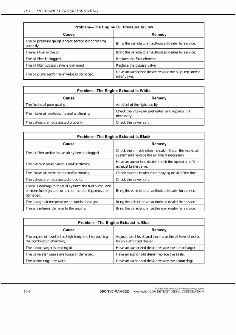
7/22/2019 Manual Mbe 4000 Taller
http://slidepdf.com/reader/full/manual-mbe-4000-taller 594/630
16.1 MECHANICAL TROUBLESHOOTING
Problem—The Engine Oil Pressure Is Low
Cause Remedy
The oil pressure gauge and/or sensor is not reading
correctly.Bring the vehicle to an authorized dealer for service.
There is fuel in the oil. Bring the vehicle to an authorized dealer for service.
The oil filter is clogged. Replace the filter element.
The oil filter bypass valve is damaged. Replace the bypass valve.
The oil pump and/or relief valve is damaged.Have an authorized dealer replace the oil pump and/or
relief valve.
Problem—The Engine Exhaust Is White
Cause Remedy
The fuel is of poor quality. Add fuel of the right quality.
The intake air preheater is malfunctioning.Check the intake air preheater, and replace it, if
necessary. The valves are not adjusted properly. Check the valve lash.
Problem—The Engine Exhaust Is Black
Cause Remedy
The air filter and/or intake air system is clogged.Check the air restriction indicator. Clean the intake air
system and replace the airfilter if necessary.
The exhaust brake valve is malfunctioning.Have an authorized dealer check the operation of the
exhaust brake valve.
The intake air preheater is malfunctioning. Check that the heater is notstaying on all of the time.
The valves are not adjusted properly. Check the valve lash.
There is damage to the f uel system: the fuel pump, one
or more fuel injectors, or one or more unit pumps are
damaged.
Bring the vehicle to an authorized dealer for service.
The charge-air temperature sensor is damaged. Bring the vehicle to an authorized dealer for service.
There is internal damage to the engine. Bring the vehicle to an authorized dealer for service.
Problem—The Engine Exhaust Is Blue
Cause Remedy
The engine oil level is too high (engine oil is reaching
the combustion chamber).
Adjust the oil level, and then have the oil level checked
by an authorized dealer.
The turbocharger is leaking oil. Have an authorized dealer replace the turbocharger
The valve stem seals are loose or damaged. Have an authorized dealer replace the seals.
The piston rings are worn. Have an authorized dealer replace the piston rings.
All information subject to change without notice.
16-8 DDC-SVC-MAN-0023 Copyright © 2009 DETROIT DIESEL CORPORATION

7/22/2019 Manual Mbe 4000 Taller
http://slidepdf.com/reader/full/manual-mbe-4000-taller 595/630
MBE 4000 SERVICE MANUAL
Problem—Engine Brake Performance Is Poor
Cause Remedy
The engine brake control switch is damaged. Replace the switch.
The exhaust brake valve is not operating properly.Have an authorized dealer check the operation of the
exhaust brake valve.
The constant-throttle valves are malfunctioning. Bring the vehicle to an authorized dealer for service.
Components of the PLD and/or VCU control unit are
damaged.Bring the vehicle to an authorized dealer for service.
Problem—Cruise Control Is Not Working
Cause Remedy
One or more of the cruise control switches are damaged. Replace the damaged switch.
Components of the PLD and/or VCU control unit are
damaged or not working properly.Bring the vehicle to an authorized dealer for service.
Problem—The Battery Charge Indicator Light Does Not Come On When the Engine Is Not Running
Cause Remedy
The bulb is damaged. Change the bulb.
The circuit is broken. Repair the break in the circuit.
Problem—The Battery Charge Indicator Light Comes On When the Engine is Running
Cause Remedy
The poly-V belt is too loose.
Check the belt tension; if necessary, have an authorized
dealer replace the belt tensioner.
The belt tensioner is damaged. Have an authorized dealer replace the belt tensioner.
The poly-V belt is worn or damaged. Replace the belt.
The alternator is damaged (has a damaged rectifier or
voltage regulator).Have an authorized dealer replace the alternator.
All information subject to change without notice.
DDC-SVC-MAN-0023 Copyright © 2009 DETROIT DIESEL CORPORATION 16-9

7/22/2019 Manual Mbe 4000 Taller
http://slidepdf.com/reader/full/manual-mbe-4000-taller 596/630
16.1 MECHANICAL TROUBLESHOOTING
All information subject to change without notice.
16-10 DDC-SVC-MAN-0023 Copyright © 2009 DETROIT DIESEL CORPORATION
7/22/2019 Manual Mbe 4000 Taller
http://slidepdf.com/reader/full/manual-mbe-4000-taller 597/630
17 LOW POWER CONCERN
Section Page
17.1 FACTORS THAT AFFECT WHEEL HORSEP OWER .............................. 17-3
17.2 LOW HORSEPOWER INTERVIEW ......................................................... 17-6
17.3 AERATED FUEL ..................................................................................... 17-13
17.4 RESTRICTED AIR CLEANER ELEMENT ............................................... 17-15
17.5 RESTRICTED OR CRACKED CHARGE AIR COOLER OR LEAKING
INTAKE MANIFOLD ................................................................................. 17-16
17.6 FAULTY EXHAUST SY STEM .................................................................. 17-18
17.7 HIGH INLET AIR TEMPERATURE .......................................................... 17-20
17.8 VERIFICATION OF POWER WITH CHASSIS DYNAMOMETER ........... 17-22

7/22/2019 Manual Mbe 4000 Taller
http://slidepdf.com/reader/full/manual-mbe-4000-taller 598/630
All information subject to change without notice.
17-2 DDC-SVC-MAN-0023 Copyright © 2009 DETROIT DIESEL CORPORATION
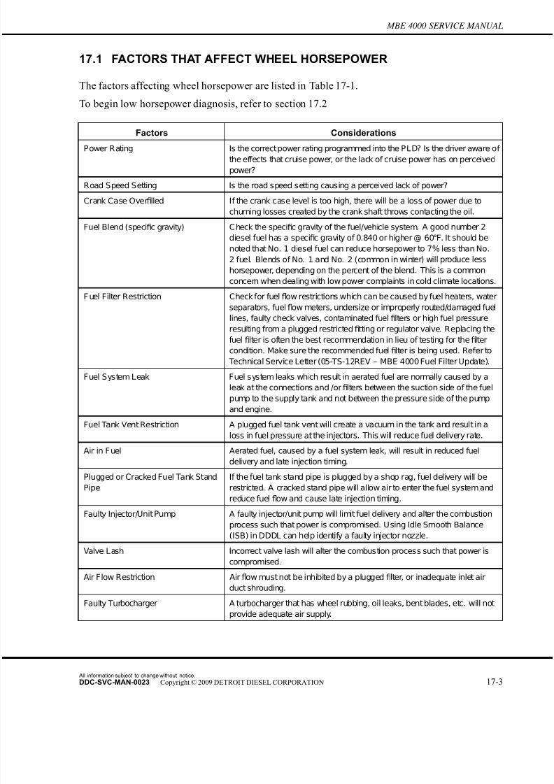
7/22/2019 Manual Mbe 4000 Taller
http://slidepdf.com/reader/full/manual-mbe-4000-taller 599/630
MBE 4000 SERVICE MANUAL
17.1 FACTORS THAT AFFECT WHEEL HORSEPOWER
The factors affecting wheel horsepower are listed in Table 17-1.
To begin low horsepower diagnosis, refer to section 17.2
Factors ConsiderationsPower Rating Is the correctpower rating programmed into the PLD? Is the driver aware of
the effects that cruise power, or the lack of cruise power has on perceived
power?
Road Speed Setting Is the road speed setting causing a perceived lack of power?
Crank Case Overfilled If the crank case level is too high, there will be a loss of power due to
churning losses created by the crank shaft throws contacting the oil.
Fuel Blend (specific gravity) C heck the specific gravity of the fuel/vehicle system. A good number 2
diesel fuel has a specific gravity of 0.840 or higher @ 60°F. It should be
noted that No. 1 diesel fuel can reduce horsepower to 7% less than No.
2 fuel. Blends of No. 1 and No. 2 (common in winter) will produce less
horsepower, depending on the percent of the blend. This is a common
concern when dealing with low power complaints in cold climate locations.
F uel Filter Restriction Check for fuel flow restrictions which can be caused by fuel heaters, water
separators, fuelflow meters, undersize or improperly routed/damaged fuel
lines, faulty check valves, contaminated fuel filters or high fuel pressure
resulting from a plugged restrictedfitting or regulator valve. Replacing the
fuel filter is often the best recommendation in lieu of testing for the filter
condition. Make sure the recommended fuel filter is being used. Refer to
Technical Service Letter (05-TS-12REV – MBE 4000 Fuel Filter Update).
Fuel System Leak Fuel system leaks which result in aerated fuel are normally caused by a
leak at the connections and /orfilters between the suction side of the fuel
pump to the supply tank and not between the pressure side of the pump
and engine.Fuel Tank Vent Restriction A plugged fuel tank vent will create a vacuum in the tank and result in a
loss in fuel pressure at the injectors. This will reduce fuel delivery rate.
Air in Fuel Aerated fuel, caused by a fuel system leak, will result in reduced fuel
delivery and late injection timing.
Plugged or Cracked Fuel Tank Stand
Pipe
If the fuel tank stand pipe is plugged by a shop rag, fuel delivery will be
restricted. A cracked stand pipe will allow air to enter the fuel system and
reduce fuel flow and cause late injection timing.
Faulty Injector/Unit Pump A faulty injector/unit pump will limit fuel delivery and alter the combustion
process such that power is compromised. Using Idle Smooth Balance
(ISB) in DDDL can help identify a faulty injector nozzle.
Valve Lash Incorrect valve lash will alter the combustion process such that power iscompromised.
Air Flow Restriction Air flow must not be inhibited by a plugged filter, or inadequate inlet air
duct shrouding.
Faulty Turbocharger A turbocharger that has wheel rubbing, oil leaks, bent blades, etc. will not
provide adequate air supply.
All information subject to change without notice.
DDC-SVC-MAN-0023 Copyright © 2009 DETROIT DIESEL CORPORATION 17-3
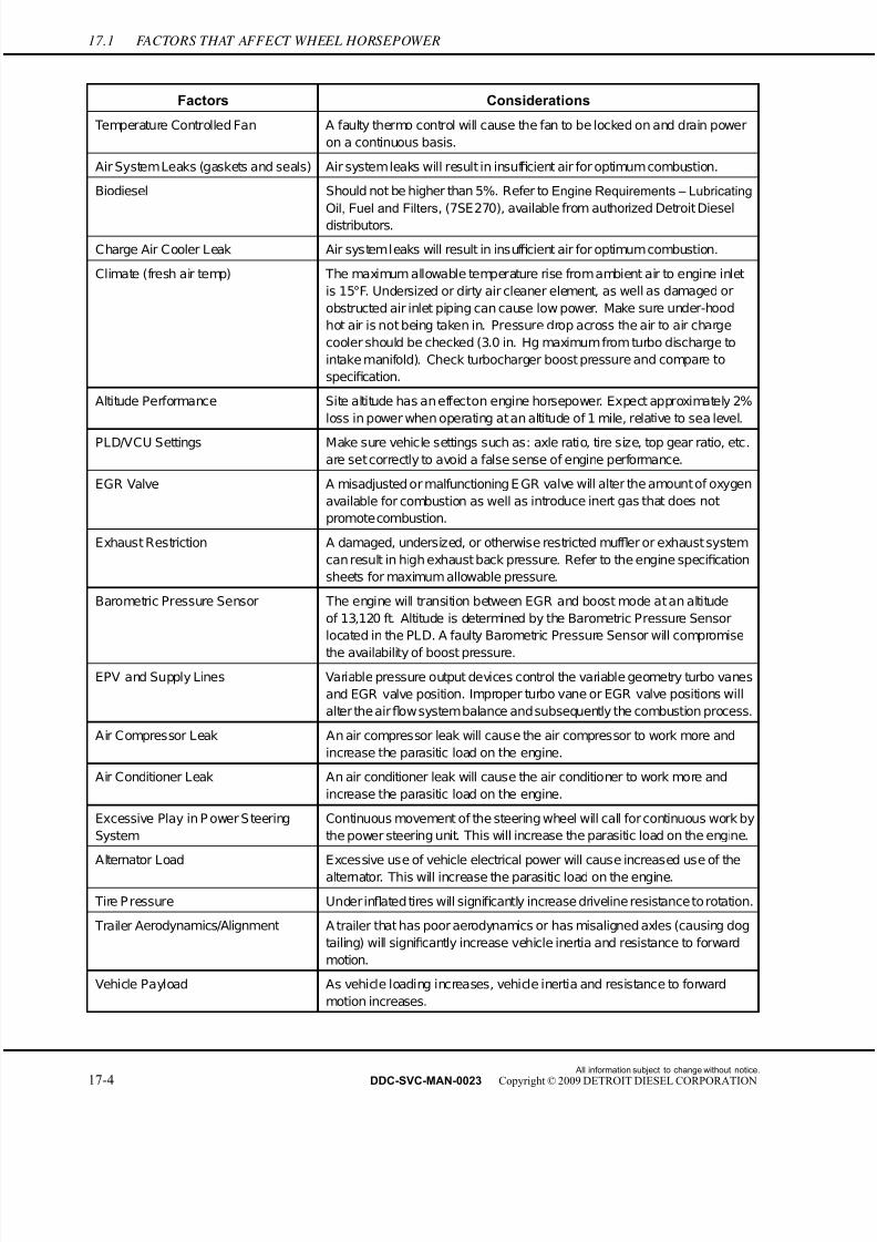
7/22/2019 Manual Mbe 4000 Taller
http://slidepdf.com/reader/full/manual-mbe-4000-taller 600/630
17.1 FACTORS THAT AFFECT WHEEL HORSEPOWER
Factors Considerations
Temperature Controlled Fan A faulty thermo control will cause the fan to be locked on and drain power
on a continuous basis.
Air SystemLeaks (gaskets and seals) Air systemleaks will result in insuf ficient air for optimum combustion.
Biodiesel Should not be higher than 5%. Refer to Engine Requirements – Lubricating
Oil, Fuel and Filters, (7SE270), available from authorized Detroit Diesel
distributors.
Charge Air Cooler Leak Air systemleaks will result in insuf ficient air for optimum combustion.
Climate (fresh air temp) The maximum allowable temperature rise from ambient air to engine inlet
is 15°F. Undersized or dirty air cleaner element, as well as damaged or
obstructed air inlet piping can cause low power. Make sure under-hood
hot air is not being taken in. Pressure drop across the air to air charge
cooler should be checked (3.0 in. Hg maximum from turbo discharge to
intake manifold). Check turbocharger boost pressure and compare to
specification.
Altitude Performance Site altitude has an effecton engine horsepower. Expect approximately 2%
loss in power when operating at an altitude of 1 mile, relative to sea level.
PLD/VCU Settings Make sure vehicle settings such as: axle ratio, tire size, top gear ratio, etc.
are set correctly to avoid a false sense of engine performance.
EGR Valve A misadjusted or malfunctioning E GR valve will alter the amount of oxygen
available for combustion as well as introduce inert gas that does not
promote combustion.
Exhaust Restriction A damaged, undersized, or otherwise restricted muf fler or exhaust system
can result in high exhaust back pressure. Refer to the engine specification
sheets for maximum allowable pressure.
Barometric Pressure Sensor The engine will transition between EGR and boost mode at an altitude
of 13,120 ft. Altitude is determined by the Barometric Pressure Sensor
located in the PLD. A faulty Barometric Pressure Sensor will compromise
the availability of boost pressure.
EPV and Supply Lines Variable pressure output devices control the variable geometry turbo vanes
and EGR valve position. Improper turbo vane or EGR valve positions will
alter the airflow systembalance andsubsequently the combustion process.
Air Compressor Leak An air compressor leak will cause the air compressor to work more and
increase the parasitic load on the engine.
Air Conditioner Leak An air conditioner leak will cause the air conditioner to work more and
increase the parasitic load on the engine.
Excessive Play in P ower S teering
System
Continuous movement of the steering wheel will call for continuous work by
the power steering unit. This will increase the parasitic load on the engine.
Alternator Load Excessive use of vehicle electrical power will cause increased use of the
alternator. This will increase the parasitic load on the engine.
Tire P ressure Under inflated tires will significantly increase driveline resistance to rotation.
Trailer Aerodynamics/Alignment A trailer that has poor aerodynamics or has misaligned axles (causing dog
tailing) will significantly increase vehicle inertia and resistance to forward
motion.
Vehicle Payload As vehicle loading increases, vehicle inertia and resistance to forward
motion increases.
All information subject to change without notice.
17-4 DDC-SVC-MAN-0023 Copyright © 2009 DETROIT DIESEL CORPORATION
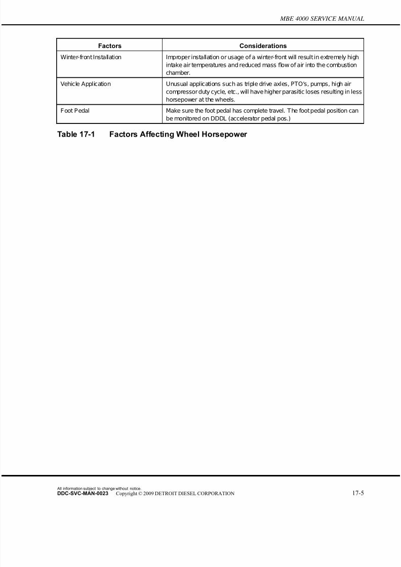
7/22/2019 Manual Mbe 4000 Taller
http://slidepdf.com/reader/full/manual-mbe-4000-taller 601/630
MBE 4000 SERVICE MANUAL
Factors Considerations
Winter-front Installation Improper installation or usage of a winter-front will result in extremely high
intake air temperatures and reduced mass flow of air into the combustion
chamber.
Vehicle Application Unusual applications such as triple drive axles, PTO's, pumps, high air
compressor duty cycle, etc., will have higher parasitic loses resulting in less
horsepower at the wheels.
Foot Pedal Make sure the foot pedal has complete travel. The footpedal position can
be monitored on DDDL (accelerator pedal pos.)
Table 17-1 Factors Affecting Wheel Horsepower
All information subject to change without notice.
DDC-SVC-MAN-0023 Copyright © 2009 DETROIT DIESEL CORPORATION 17-5

7/22/2019 Manual Mbe 4000 Taller
http://slidepdf.com/reader/full/manual-mbe-4000-taller 602/630
17.2 LOW HORSEPOWER INTERVIEW
17.2 LOW HORSEPOWER INTERVIEW
To determine if low horsepower is causing a power concern, use the driver questionna ire, the
troubleshooting tree, and the low power troubleshooting chart.
17.2.1 Driver Questionnaire
This section should serve as a guideline for the technician.
All information subject to change without notice.
17-6 DDC-SVC-MAN-0023 Copyright © 2009 DETROIT DIESEL CORPORATION
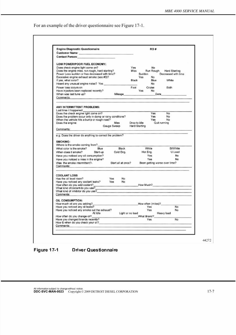
7/22/2019 Manual Mbe 4000 Taller
http://slidepdf.com/reader/full/manual-mbe-4000-taller 603/630
MBE 4000 SERVICE MANUAL
For an example of the driver questionnaire see Figure 17-1.
Figure 17-1 Driver Questionnaire
All information subject to change without notice.
DDC-SVC-MAN-0023 Copyright © 2009 DETROIT DIESEL CORPORATION 17-7

7/22/2019 Manual Mbe 4000 Taller
http://slidepdf.com/reader/full/manual-mbe-4000-taller 604/630
17.2 LOW HORSEPOWER INTERVIEW
17.2.1.1 Driver Questionnaire
Ask the driver to answer the following questions before attempting to repair an intermittent
problem, or a problem with symptoms but no diagnostic codes. Use this and the response as a
guideline. Refer to section 17.2.1.2, “Questionnaire Response Guideline.”
1. How often does the problem occur? Can you and the driver take the vehicle and
demonstrate the problem in less than 30 minutes?
2. Has the vehicle been to other shops for the same problem? If so, what was done there?
3. Did the radio, dash gages, or lights momentarily turn OFF when the problem occurred?
4. Does the problem occur only at specific operating conditions? If so, at what load? Is it
light, medium, or heavy?
5. Does the problem occur at a specific engine operating temperature? If so, at what engine
temperature?
6. Does the problem occur at a specific engine operating altitude? If so, at what altitude?
7. Does the problem occur only when above or below specific outside temperatures? If so,what temperature range?
8. Does the problem occur during other conditions e.g. during or after rain, spray washing,
snow?
9. Did the problem occur at a specific vehicle speed? If so, at what vehicle speed?
10. Does the problem occur at specific engine RPM? If so, at what engine RPM?
17.2.1.2 Questionnaire Response Guideline
The following are typical r esponses to the driver questionnaire:
PERSONAL INJURY
To avoid injury from loss of vehicle/vessel control, theoperator of a MBE electronic controlled engine must notuse or read any diagnostic tool while the vehicle/vessel ismoving.
1. If the problem is repeatable, take the vehicle for a drive with Detroit Diesel Diagnostic
Link (DDDL) connected and note the conditions when the problem occurs. Be prepared to
take snapshot data using DDDL. Ensure you operate the vehicle after correcting the
problem and duplicate the operating conditions before releasing the unit, in order to
verify the problem is corrected.
2. If the vehicle has been to other shops for the same problem, call the other shops and find
out what has been done. Avoid replacing the same components again unless absolutely
All information subject to change without notice.
17-8 DDC-SVC-MAN-0023 Copyright © 2009 DETROIT DIESEL CORPORATION

7/22/2019 Manual Mbe 4000 Taller
http://slidepdf.com/reader/full/manual-mbe-4000-taller 605/630
MBE 4000 SERVICE MANUAL
sure they are the problem! It is unlikely a component will fail again following a recent
replacement.
3. If other vehicle devices are affected, this indicates there may be something wrong with
the ignition wiring.
4. Operate the engine under similar load and temperature conditions. Check the fuel system
for restrictions, fuelfi
lter, and fuel tanks for foreign objects blocking the fuel supply. Also,check the air system. Utilize the DDDL snapshot feature.
5. Operate the engine at this temperature while attempting to duplicate the problem. Use the
DDDL snapshot feature.
6. It may not be possible to duplicate the fault or problem unless you can operate the unit in a
similar environment. You may want to talk to the Customer Support Center, or a dealer in
that area. They may have helpful experience.
7. If possible, troubleshoot the problem in a similar temperature range.
8. If the problem seems to occur during or after the engine is subjected to rain/spray washing,
thoroughly inspect the connectors for moisture entry.
9. If the problem occurs at a specific vehicle speed, check the parameters affecting vehicle
speed to verify they are programmed close to the vehicle speed where the problem occurs.
Check vehicle speed and watch DDDL (snapshot) for changes to see if the pulse wheel
(VSS signal) is loose.
10. If the problem occurs at a specific engine rpm, unplug the oil, coolant, and air temperature
sensors, and note any changes to the problem. Gather this data and contact the DDC
Customer Support Center at 313-592-5800.
All information subject to change without notice.
DDC-SVC-MAN-0023 Copyright © 2009 DETROIT DIESEL CORPORATION 17-9
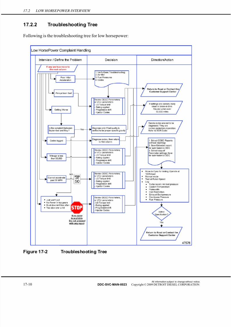
7/22/2019 Manual Mbe 4000 Taller
http://slidepdf.com/reader/full/manual-mbe-4000-taller 606/630
17.2 LOW HORSEPOWER INTERVIEW
17.2.2 Troubleshooting Tree
Following is the troubleshooting tree for low horsepower:
Figure 17-2 Troubleshooting Tree
All information subject to change without notice.
17-10 DDC-SVC-MAN-0023 Copyright © 2009 DETROIT DIESEL CORPORATION
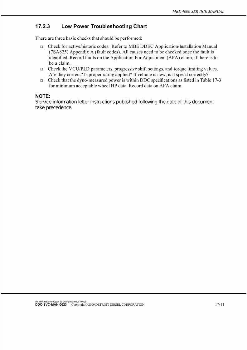
7/22/2019 Manual Mbe 4000 Taller
http://slidepdf.com/reader/full/manual-mbe-4000-taller 607/630
MBE 4000 SERVICE MANUAL
17.2.3 Low Power Troubleshooting Chart
There are three basic checks that should be performed:
□ Check for active/historic codes. Refer to MBE DDEC Application/Installation Manual
(7SA825) Appendix A (fault codes). All causes need to be checked once the fault is
identified. Record faults on the Application For Adjustment (AFA) claim, if there is to
be a claim.
□ Check the VCU/PLD parameters, progressive shift settings, and torque limiting values.
Are they correct? Is proper rating applied? If vehicle is new, is it spec'd correctly?
□ Check that the dyno-measured power is within DDC specifications as listed in Table 17-3
for minimum acceptable wheel HP data. Record data on AFA claim.
NOTE:Service information letter instructions published following the date of this documenttake precedence.
All information subject to change without notice.
DDC-SVC-MAN-0023 Copyright © 2009 DETROIT DIESEL CORPORATION 17-11
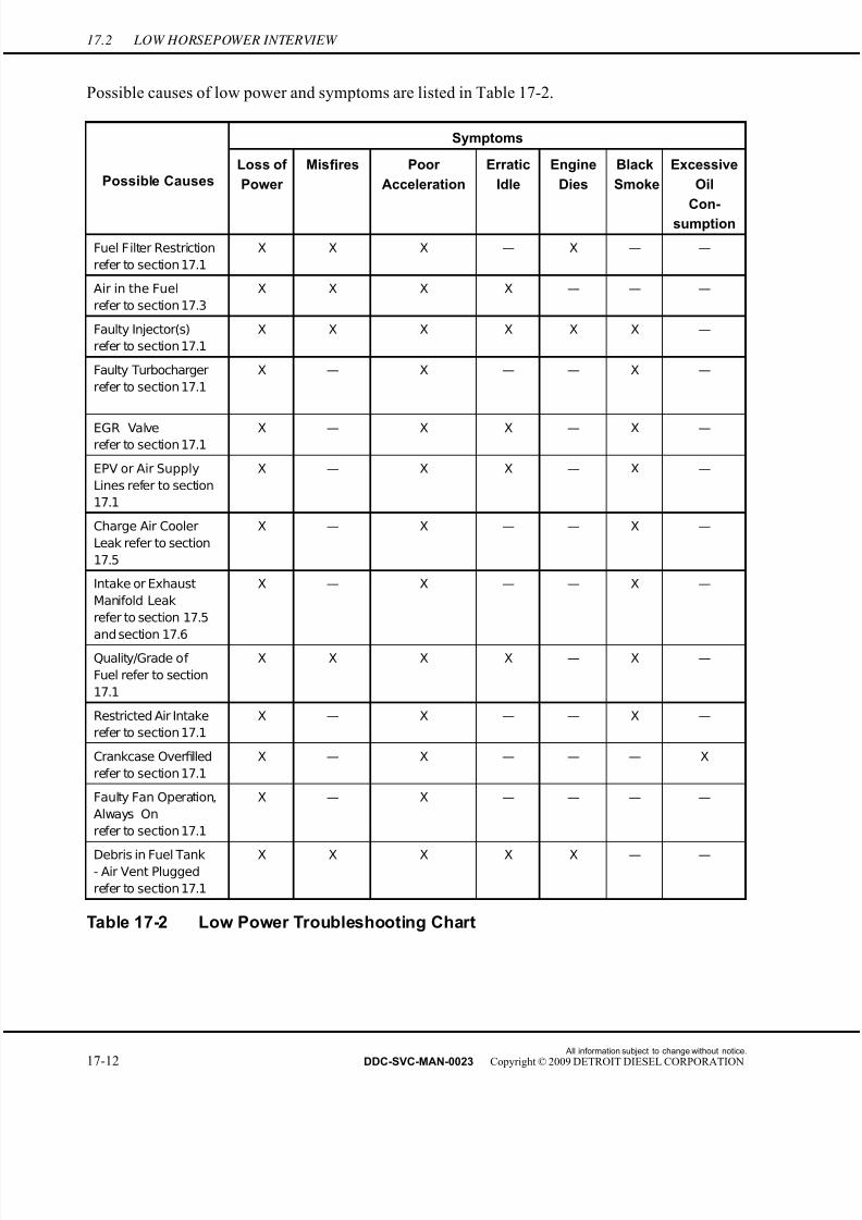
7/22/2019 Manual Mbe 4000 Taller
http://slidepdf.com/reader/full/manual-mbe-4000-taller 608/630
17.2 LOW HORSEPOWER INTERVIEW
Possible causes of low power and symptoms are listed in Table 17-2.
Symptoms
Possible CausesLoss of
Power
Misfires Poor
Acceleration
Erratic
Idle
Engine
Dies
Black
Smoke
Excessive
Oil
Con-
sumption
Fuel Filter Restriction
refer to section 17.1
X X X — X — —
Air in the Fuel
refer to section 17.3
X X X X — — —
Faulty Injector(s)
refer to section 17.1
X X X X X X —
Faulty Turbocharger
refer to section 17.1
X — X — — X —
EGR Valverefer to section 17.1
X — X X — X —
EPV or Air Supply
Lines refer to section
17.1
X — X X — X —
Charge Air Cooler
Leak refer to section
17.5
X — X — — X —
Intake or Exhaust
Manifold Leak
refer to section 17.5
and section 17.6
X — X — — X —
Quality/Grade of
Fuel refer to section
17.1
X X X X — X —
Restricted Air Intake
refer to section 17.1
X — X — — X —
Crankcase Overfilled
refer to section 17.1
X — X — — — X
Faulty Fan Operation,
Always On
refer to section 17.1
X — X — — — —
Debris in Fuel Tank- Air Vent Plugged
refer to section 17.1
X X X X X — —
Table 17-2 Low Power Troubleshooting Chart
All information subject to change without notice.
17-12 DDC-SVC-MAN-0023 Copyright © 2009 DETROIT DIESEL CORPORATION
7/22/2019 Manual Mbe 4000 Taller
http://slidepdf.com/reader/full/manual-mbe-4000-taller 609/630
MBE 4000 SERVICE MANUAL
17.3 AERATED FUEL
To determine if aerated fuel is causing lack of power, perform the following steps:
1. Disconnect the fuel line return hose from the fitting located at the fuel tank; refer to OEM
guidelines.
2. Place the open end of the fuel line into a suitable container.
To avoid injury before starting and running the engine,ensure the vehicle is parked on a level surface, parkingbrake is set, and the wheels are blocked.
ENGINE EXHAUSTTo avoid injury from inhaling engine exhaust, alwaysoperate the engine in a well-ventilated area. Engineexhaust is toxic.
3. Start and run the engine.
4. Operate the engine at 1000 rpm.
5. Visually check to see if air bubbles are rising to the surface of the fuel within the container.
[a] If air bubbles are not present, shut down engine, check for high fuel pressure;
refer to section 17.4.[b] If air bubbles are present, shut down engine; refer to section 17.3.1.
17.3.1 Aerated Fuel Resolution
Perform the following steps to resolve aerated fuel:
1. Tighten all fuel line connections between the fuel tank and fuel pump; refer to OEM
guidelines.
2. Visually inspect all fuel lines between the fuel tank and fuel pump for leaks.
3. Repair damaged components as required; refer to OEM guidelines.
4. Verify aerated fuel resolution; refer to section 17.3.1.1.
17.3.1.1 Test the Engine with Aerated Fuel Resolution
Perform the following steps to determine if aerated fuel resolution resolved lack of power
condition:
All information subject to change without notice.
DDC-SVC-MAN-0023 Copyright © 2009 DETROIT DIESEL CORPORATION 17-13
7/22/2019 Manual Mbe 4000 Taller
http://slidepdf.com/reader/full/manual-mbe-4000-taller 610/630
17.3 AERATED FUEL
1. Start and run the engine.
2. Run the engine at idle with a no-load for approximately 5 minutes, allowing the engine
coolant to reach normal operating range.
3. Test drive the vehicle to ensure lack of power has been resolved.
[a] If no lack of power occurred during the test drive, no further troubleshooting is
required. Shut down the engine.
[b] If lack of power occurred during the test drive, shut down the engine and .
refer to section 17.4.
All information subject to change without notice.
17-14 DDC-SVC-MAN-0023 Copyright © 2009 DETROIT DIESEL CORPORATION

7/22/2019 Manual Mbe 4000 Taller
http://slidepdf.com/reader/full/manual-mbe-4000-taller 611/630
MBE 4000 SERVICE MANUAL
17.4 RESTRICTED AIR CLEANER ELEMENT
To determine if a restricted air cleaner element is causing lack of power, perform th e following
steps:
1. Remove the air filter element from the air cleaner container; refer to OEM guidelines.
2. Visually inspect the air cleaner element for damage or clogging.[a] If no damage or clogging is found, check the charge air cooler; refer to section 17.5.
[b] If damage or clogging is found; refer to section 17.4.1.
NOTE:Replace the air filter, if close to a maintenance interval.
17.4.1 Air Filter Element Replacement
Perform the following steps to replace the air filter element:
1. Remove and replace the damaged or clogged air filter element; refer to OEM guidelines.
2. Verify air filter element replacement; refer to section 17.4.1.1.
17.4.1.1 Test the Engine with Replaced Air Filter Element
Perform the following steps to determine if the new filter element resolved lack of power:
To avoid injury before starting and running the engine,
ensure the vehicle is parked on a level surface, parkingbrake is set, and the wheels are blocked.
ENGINE EXHAUST
To avoid injury from inhaling engine exhaust, alwaysoperate the engine in a well-ventilated area. Engineexhaust is toxic.
1. Start and run the engine.
2. Test drive the vehicle to ensure lack of power has been resolved.
[a] If lack of power did not occur during the test drive, no further troubleshooting is
required. Shut down the engine.
[b] If lack of power occurred during the test drive, shut down the engine. Check the
charge air cooler; refer to section 17.5.
All information subject to change without notice.
DDC-SVC-MAN-0023 Copyright © 2009 DETROIT DIESEL CORPORATION 17-15
7/22/2019 Manual Mbe 4000 Taller
http://slidepdf.com/reader/full/manual-mbe-4000-taller 612/630
17.5 RESTRICTED OR CRACKED CHARGE AIR COOLER OR LEAKING INTAKE MANIFOLD
17.5 RESTRICTED OR CRACKED CHARGE AIR COOLER OR LEAKINGINTAKE MANIFOLD
To determine if a restricted or cracked charge air cooler or leaking manifold is causing lack of
power, perform the following steps:
1. Attach air-to-air charge air cooler test kit, (J-41473); refer to OEM guidelines.
2. Disconnect the air inlet hose from the outlet side of the turbochar ger compressor housing;
refer to appropriate service manual, air intake system chapter.
3. Attach the air-to-air cooler test kit adaptor plug to fit into the hose at the compressor
connector; refer to OEM guidelines.
4. Attach an air pressure hose to the air chuck at the regulator and gradually pressurize the
air inlet system to a pressure of 207 kPa (30 psi).
5. Apply a water and soap solution to each hose connection, across the face of the charge
air cooler.
6. Apply a water and soap solution to the air intake manifold and cylinder head matingsurface area.
7. Visually inspect all joints for air leaks and all charge air cooler welded surfaces for
stress cracks.
[a] If charge air cooler leaks are present around the joints, replace the charge air cooler;
refer to section 17.5.1.
[b] If the intake manifold leaks, repair intake manifold; refer to section 17.5.2.
[c] If neither charge air cooler nor intake manifold leaked, check the exhaust system;
refer to section 17.6.
8. Inspect charge air cooler for leaks (hoses, clamps, etc.).
17.5.1 Charge Air Cooler Replacement
Perform the following steps to replace the charge air cooler:
1. Remove and replace the charge air cooler; refer to OEM guidelines.
2. If the intake manifold doesn't leak, verify replacement of the charge air cooler;
refer to section 17.5.2.1.
3. If the intake manifold leaks, repair intake manifold; refer to section 17.5.2.
17.5.2 Air Intake Manifold Repair
Perform the following steps to repair the air intake manifold:
1. Remove the air intake manifold; refer to MBE 4000 Service Manual (6SE412), Air
system chapter 6.1.
All information subject to change without notice.
17-16 DDC-SVC-MAN-0023 Copyright © 2009 DETROIT DIESEL CORPORATION

7/22/2019 Manual Mbe 4000 Taller
http://slidepdf.com/reader/full/manual-mbe-4000-taller 613/630
MBE 4000 SERVICE MANUAL
2. Inspect the air intake manifold; refer to MBE 4000 Service Manual (6SE412), Air system
chapter 6.1.
3. Install the air intake manifold; refer to MBE 4000 Service Manual (6SE412), Air system
chapter 6.1.2.
4. Verify repair of the intake manifold; refer to section 17.5.2.1.
17.5.2.1 Test the Engine with Replaced Charge Air Cooler and Air IntakeManifold
To determine if the repairs resolved the lack of power condition, perform the following steps:
To avoid injury before starting and running the engine,ensure the vehicle is parked on a level surface, parking
brake is set, and the wheels are blocked.
ENGINE EXHAUST
To avoid injury from inhaling engine exhaust, alwaysoperate the engine in a well-ventilated area. Engineexhaust is toxic.
1. Start and run the engine.
2. Test drive the vehicle to ensure lack of power has been resolved.
[a] If no lack of power occurred during the test drive, no further troubleshooting is
required. Shut down the engine.
[b] If lack of power occurred during the test drive, shut down the engine. Check the
exhaust system; refer to section 17.6.
All information subject to change without notice.
DDC-SVC-MAN-0023 Copyright © 2009 DETROIT DIESEL CORPORATION 17-17

7/22/2019 Manual Mbe 4000 Taller
http://slidepdf.com/reader/full/manual-mbe-4000-taller 614/630
17.6 FAULTY EXHAUST SYSTEM
17.6 FAULTY EXHAUST SYSTEM
To determine if a faulty exhaust system is causing lack of power, perform the following steps:
1. Drill an 11/32 in. hole in the exhaust pipe, 127 - 305 mm (5 - 12 in.) from the turbocharger
exhaust outlet.
NOTE: The tapped hole must be in a comparatively straight area of the turbocharger exhaustoutlet.
2. Tap the hole to accommodate a 1/8 in. pipe plug. Connect a manometer to the tapped hole.
To avoid injury before starting and running the engine,ensure the vehicle is parked on a level surface, parking
brake is set, and the wheels are blocked.
ENGINE EXHAUST
To avoid injury from inhaling engine exhaust, alwaysoperate the engine in a well-ventilated area. Engineexhaust is toxic.
3. Start and run the engine at idle with a no-load for approximately 5 minutes, allowing the
engine coolant to reach normal operating range.4. Install the vehicle on a chassis dynamometer and run the engine speed to full load.
[a] If the exhaust back pressure at full load is less than 10 kPa (4.0 in. H2O), check for
high inlet air temperature; refer to section 17.7.
[b] If the exhaust back pressure at full load is 10 kPa (4.0 in. H2O) or greater,
refer to section 17.6.1.
17.6.1 Engine Exhaust System Resolution
Perform the following steps to resolve the engine exhaust system:
1. Visually inspect the engine exhaust system; refer to OEM guidelines.
2. Repair or replace defective exhaust system components; refer to OEM guidelines.
3. Verify exhaust system resolution; refer to section 17.6.1.1.
All information subject to change without notice.
17-18 DDC-SVC-MAN-0023 Copyright © 2009 DETROIT DIESEL CORPORATION
7/22/2019 Manual Mbe 4000 Taller
http://slidepdf.com/reader/full/manual-mbe-4000-taller 615/630
MBE 4000 SERVICE MANUAL
17.6.1.1 Test the Engine with Replaced Exhaust System
Perform the following steps to determine if replaced engine exhaust system components resolved
lack of power condition:
1. Start and run the engine.
2. Test drive the vehicle to ensure lack of power has been resolved.[a] If no lack of power occurred during the test drive, no further troubleshooting is
required. Shut down the engine.
[b] If lack of power occurred during the test drive, shut down the engine. Check for high
inlet air temperature; refer to section 17.7.
All information subject to change without notice.
DDC-SVC-MAN-0023 Copyright © 2009 DETROIT DIESEL CORPORATION 17-19

7/22/2019 Manual Mbe 4000 Taller
http://slidepdf.com/reader/full/manual-mbe-4000-taller 616/630
17.7 HIGH INLET AIR TEMPERATURE
17.7 HIGH INLET AIR TEMPERATURE
To determine if high inlet air temperature is causing lack of power, perform the following:
1. Test the radiator fan, fan drive, or fan shroud for proper operation or configuration; refer
to OEM guidelines.
NOTE: The engine will be torque limited to protect the turbocharger and charge air cooler; this isnormal engine operation for component protection.
2. Examine test results.
[a] If the radiator fan, fan drive, or fan shroud pass OEM test, check high altitude
operation.
[b] If the radiator fan, drive or shroud did not operate cor rectly; refer to section 17.7.1.
17.7.1 Radiator Fan, Drive and Shroud Replacement
Perform the following steps to replace the radiator fan, drive and or shroud:
1. Remove and replace the radiator fan, drive and/or shroud; refer to OEM guidelines.
2. Verify replacement; refer to section 17.7.1.1.
17.7.1.1 Test the Engine with Radiator Fan, Fan Drive, or Fan ShroudReplacement
Perform the following steps to determine if replaced radiator fan, fan drive, or fan shroud resolved
lack of power condition:
To avoid injury before starting and running the engine,ensure the vehicle is parked on a level surface, parkingbrake is set, and the wheels are blocked.
ENGINE EXHAUSTTo avoid injury from inhaling engine exhaust, alwaysoperate the engine in a well-ventilated area. Engineexhaust is toxic.
1. Start and run the engine.
2. Test drive the vehicle to ensure lack of power has been resolved.
All information subject to change without notice.
17-20 DDC-SVC-MAN-0023 Copyright © 2009 DETROIT DIESEL CORPORATION
7/22/2019 Manual Mbe 4000 Taller
http://slidepdf.com/reader/full/manual-mbe-4000-taller 617/630
MBE 4000 SERVICE MANUAL
[a] If no lack of power occurred during the test drive, no further troubleshooting is
required. Shut down the engine.
[b] If lack of power occurred during the test drive, shut down the engine, contact the
Detroit Diesel Customer Support Center (313–592–5800).
All information subject to change without notice.
DDC-SVC-MAN-0023 Copyright © 2009 DETROIT DIESEL CORPORATION 17-21

7/22/2019 Manual Mbe 4000 Taller
http://slidepdf.com/reader/full/manual-mbe-4000-taller 618/630
17.8 VERIFICATION OF POWER WITH CHASSIS DYNAMOMETER
17.8 VERIFICATION OF POWER WITH CHASSIS DYNAMOMETER
The chassis dynamometer is a device for applying specific loads to a vehicle to determine if the
vehicle will perform to published specifications and to permit a physical inspection for leaks of
any kind. It is an excellent method for detecting improper tune-up, misfiring injectors, low
compression, and other malfunctions.
17.8.1 Chassis Dynamometer Room Ventilation Recommendations
For safe and accurate dynamometer readings, the chassis dynamometer room must be properly
ventilated.
To avoid injury before starting and running the engine,ensure the vehicle is parked on a level surface, parking
brake is set, and the wheels are blocked.
ENGINE EXHAUST
To avoid injury from inhaling engine exhaust, alwaysoperate the engine in a well-ventilated area. Engineexhaust is toxic.
If a vehicle is tested on a dynamometer located in an area without proper ventilation, the engine
will be subject to high ambient air temperatures. High air inlet temperatures can result in falselow power readings on the dynamometer.
To help ensure accurate horsepower readings, the dynamometer room should have a
ceiling-mounted fan with a 850 to 1133 m3 /min (30,000 to 40,000 ft3 /min) capacity. This will
provide proper ventilation of exhaust gases and heat radiated by the operating engine.
For direct engine cooling, Detroit Diesel recommends the use of a 368 m3 /min (13,000 ft3 /min)
or greater capacity barrel-type ram air fan. This should be portable so that it can be conveniently
placed three to five feet (approximately one to two meters) in front of the truck and aimed directly
at the radiator/charge air cooler package.
17.8.2 Chassis Dynamometer Test and Run-in Procedure
The function of the dynamometer is to absorb and measure the engine output after it has been
transmitted through the vehicle transmission and driveline to the drive tires.
All information subject to change without notice.
17-22 DDC-SVC-MAN-0023 Copyright © 2009 DETROIT DIESEL CORPORATION
7/22/2019 Manual Mbe 4000 Taller
http://slidepdf.com/reader/full/manual-mbe-4000-taller 619/630
MBE 4000 SERVICE MANUAL
The vehicle is connected to dynamometer through the roller absorption unit. The load on the
vehicle may be varied from zero to maximum by decreasing or increasing the resistan ce in the
unit. The amount of power absorbed in a water brake type dynamometer, as an example, is
governed by the volume of fluid within the working system. The fluid offers resistance to a
rotating motion. By controlling the volume of water in the absorption unit, the load may be
increased or decreased as required.
The following are some tips to keep in mind in preparing the vehicle before the dynamometer run and during the actual testing:
□ Follow all applicable safety procedures from the chassis dynamometer manufacturer.
□ Observe the air intake duct and charge air fan shrouding to identify misalignments. Correct
as necessary.
□ Make sure the differential lock is “on” if equipped.
□ Make sure the radiator/charge air cooler system fan(s) are locked on.
□ If the vehicle is equipped with anti-lock brakes (ABS), disa ble the ABS controller by
unplugging it or removing its power fuse/breaker.
□ Instrument the engine for fuel pressure, air inlet restriction, exhaust backpressure, and
crankcase pressure, and note these readings during the dynamometer run.□ Make sure the vehicle hood is down and locked into its normal position.
□ Make sure the engine is fully warmed up before placing the vehicle on the dynamometer.
Both oil and coolant temperature should be at least 82°C (180°F).
□ When loading the vehicle on the dynamometer, make sure the vehicle is positioned onto
the rollers as straight as possible.
□ For direct engine cooling, Detroit Diesel recommends the use of a 368 m3 /min (13,000
ft3 /min) or greater capacity barrel-type ram air fan. This should be portable so that it
can be conveniently placed three to five feet (approximately one to two meters) in front
of the truck and aimed directly at the charge air cooler. This is especially important at
high altitudes.
□ During high ambient temperature conditions [+90°F, (+32°C)], it may also be necessary touse a water spray mist fan in front of the ve hicle to prevent overheating.
□ Running the dynamometer in “manual” mode instead of “automatic” mode allows for
maximum control of the test process and may result in more consistent test results.
□ During the horsepower test, make sure “percent engine load” is 100% and smoke limited is
not active by monitoring them with a computer equipped with DDDL.
□ Select a transmission gear with a 1:1 gear ratio during the horsepower test.
□ Take horsepower reading at 1300 rpm and 1850 rpm. Stabilize at rated speed for at least
one minute before taking a final horsepower reading. Compare the recorded horsepower to
the appropriate minimum horsepower tables below for particular ratings.
All information subject to change without notice.
DDC-SVC-MAN-0023 Copyright © 2009 DETROIT DIESEL CORPORATION 17-23

7/22/2019 Manual Mbe 4000 Taller
http://slidepdf.com/reader/full/manual-mbe-4000-taller 620/630
17.8 VERIFICATION OF POWER WITH CHASSIS DYNAMOMETER
□ Note that the following charts are for vehicles with manual transmissions. Vehicles with
automatic transmissions (i.e. equipped with torque converters) will have slightly lower
minimum horsepower values then listed in Table 17-3.
MBE 4000 (Model 460)
Minimum Acceptable Wheel HP @Engine HP Rating (Peak Torque)
1500 rpm 1750 rpm
350 bhp @ 1900 RPM (1350 lb-ft @ 1100 RPM) 258 272
370 bhp @ 1900 RPM (1350 lb-ft @ 1100 RPM) 258 287
370 bhp @ 1900 (1450 lb-ft @ 1100 RPM) 276 287
410 bhp @ 1900 (1450 lb-ft @ 1100 RPM) 276 318
410 bhp @ 1900 (1550 lb-ft @ 1100 RPM) 295 318
435 bhp @ 1900 (1450 lb-ft @ 1100 RPM) 276 338
435 bhp @ 1900 (1550 lb-ft @ 1100 RPM) 295 338
450 bhp @ 1900 (1550 lb-ft @ 1100 RPM) 295 349
Table 17-3 Minimum Acceptable Wheel HP Model 460
All information subject to change without notice.
17-24 DDC-SVC-MAN-0023 Copyright © 2009 DETROIT DIESEL CORPORATION
7/22/2019 Manual Mbe 4000 Taller
http://slidepdf.com/reader/full/manual-mbe-4000-taller 621/630
INDEX
AAdjusting Valve Lash, 12-9
Aerated Fuel, 17-13
Aerated Fuel Resolution, 17-13Test the Engine with Aerated Fuel Resolution, 17-13
Air Compressor , 10-5
Air Compressor Installation, 10-9
Removal, 10-5
Air Compressor Inspection, 10-8
Air Compressor Flange, 10-3
Installation, 10-4
Removal, 10-3
CCamshaft and Camshaft Position Sensor , 1-171
Camshaft Installation, 1-177
Camshaft Position Sensor Replacement, 1-179
Camshaft Removal, 1-171
Camshaft Inspection, 1-175
Camshaft Lubrication Sprayer , 3-17
Camshaft Lubrication Sprayer Installation, 3-18
Camshaft Lubrication Sprayer Removal, 3-17
Charge Pressure/Temperature Sensor , 6-5
Charge Pressure/Temperature Sensor Installation, 6-5
Charge Pressure/Temperature Sensor Removal, 6-5
Coolant, 5-7
Batteries, 5-11
Corrosion Inhibitors, 5-9
Dropout, 5-10Disposal, 5-11
Fully Formulated Antifreeze, 5-7
Non-approved Coolants, 5-11
Recycled Antifreeze, 5-9
Supplemental Coolant Additives, 5-8
Water , 5-7
All information subject to change without notice.
DDC-SVC-MAN-0023 Copyright © 2009 DETROIT DIESEL CORPORATION Index-1

7/22/2019 Manual Mbe 4000 Taller
http://slidepdf.com/reader/full/manual-mbe-4000-taller 622/630
INDEX
Coolant Specifications and Concentration, 5-8
Coolant Pump, 4-7
Coolant Pump Assembly, 4-13
Coolant Pump Disassembly, 4-10
Coolant Pump Inspection, 4-12
Coolant Pump Installation, 4-16
Coolant Pump Removal, 4-7
Coolant Temperature Sensor , 4-29
Coolant Temperature Sensor Assembly, 4-30
Coolant Temperature Sensor Disassembly, 4-29
Cooling System, 4-3
Cooling System Draining and Flushing, 4-3
Crankshaft Assembly, 1-68
Crankshaft Gear Replacement, 1-89
Crankshaft Installation, 1-86
Crankshaft Removal, 1-68
Crankshaft End Play Checking, 1-82
Crankshaft Measuring and Inspection, 1-72
Crankshaft Radial Play Checking, 1-77
crankshaft Seal wear sleeve, 1-63
Front Crankshaft Seal Wear Sleeve Installation, 1-64
Front Crankshaft Seal Wear Sleeve Removal, 1-63Rear Crankshaft Seal Wear Sleeve Installation, 1-66
Rear Crankshaft Seal Wear Sleeve Removal, 1-65
Crankshaft Vibration Damper , 1-93
Crankshaft Vibration Damper Installation, 1-94
Crankshaft Vibration Damper Removal, 1-93
Cylinder Block , 1-22
Cylinder Block Preparation, 1-37
Cylinder Liner Removal, 1-22Cylinder Block Leak Test, 1-35
Cylinder Liner Bore Inspection and Measurement, 1-25
Fuel System Leak Test, 1-32
Measurement, 1-29
Installation, 1-40
Cylinder Head, 1-4
All information subject to change without notice.
Index-2 DDC-SVC-MAN-0023 Copyright © 2009 DETROIT DIESEL CORPORATION

7/22/2019 Manual Mbe 4000 Taller
http://slidepdf.com/reader/full/manual-mbe-4000-taller 623/630
MBE 4000 SERVICE MANUAL
Cylinder Head Installation, 1-13
Engine Compression Testing, 1-18
Cylinder Head Removal, 1-4
Cylinder Head Inspection and Machining, 1-8
Cylinder Head Leak Testing, 1-11
Cylinder Head Cover , 1-3
Installation, 1-3
Removal, 1-3
DDdec-electronic Control Unit, 2-39
DDEC Electronic Control Unit Installation, 2-42
Ddec-electronic Control Unit Removal, 2-39
Drive Belts, 8-3Air Conditioner Compressor Belt Installation, 8-10
Air Conditioner Compressor Belt Removal, 8-8
Air Conditioner Compressor Pad Installation, 8-14
Air Conditioner Compressor Pad Removal, 8-13
Belt Tensioner Installation, 8-12
Belt Tensioner Removal, 8-11
Fan Belt Installation, 8-7
Fan Belt Removal, 8-6
Idler Pulley Installation, 8-13
Idler Pulley Removal, 8-12
Main Drive Belt Installation, 8-5
Main Drive Belt Removal, 8-3
EEGR Camshaft, 1-181
EGR Camshaft Changes, 1-181
EGR Control valve, gas outlet pipe, and gas mixer , 7-47
Installation, 7-52
Removal, 7-47
EGR Coolant Pump, 4-18
EGR Cooler and Cooler Support Bracket, 7-26
EGR Cooler and Support Bracket Installation, 7-34
EGR Cooler Inspection, 7-42
All information subject to change without notice.
DDC-SVC-MAN-0023 Copyright © 2009 DETROIT DIESEL CORPORATION Index-3
7/22/2019 Manual Mbe 4000 Taller
http://slidepdf.com/reader/full/manual-mbe-4000-taller 624/630
INDEX
EGR Cooler Leak Test, 7-44
EGR Cooler and Support Bracket Removal, 7-26
EGR Cylinder Head and Block , 1-44
Cylinder Block Changes, 1-46
Cylinder Head Changes, 1-45
Cylinder Liner Changes, 1-45
EGR Cylinder Head Installation, 1-44
EGR Exhaust Manifold, 7-14
EGR Exhaust Manifold Installation, 7-22
EGR Exhaust Manifold Removal, 7-14
EGR Front and Rear Lifter Brackets, 1-47
Installation, 1-48
Removal, 1-47
EGR Fuel Injector Nozzle, 2-34
EGR Injector Unit Pump, 2-15
EGR Injector Unit Pump Programming, 2-15
EGR Piston, Piston Ring, and Connecting Rod, 1-140
Piston Installation, 1-141
Piston Removal, 1-140
EGR Thermostat housing, 4-27
EGR Thermostat Housing Cover Installation, 4-27
EGR Thermostat Housing Cover Removal, 4-27
EGR Valves, 1-162
Valve Installation in the EGR Engine, 1-163
Valve Removal in the EGR Engine, 1-162
Valve Seats, 1-166
Valve Stem Seal and Valve Stem Sealing Ring Replacement in the EGR Engine , 1-164
Electronic Engine Control System, 15-3
Engine Barring Tool, 1-112
Engine Barring Tool Installation, 1-112Engine Barring Tool Removal, 1-113
Engine Brake, 1-49
Constant Throttle Valve Installation, 1-52
Constant Throttle Valve Removal, 1-49
Constant Throttle Valve Solenoid Installation, 1-54
Constant Throttle Valve Solenoid Removal, 1-53
All information subject to change without notice.
Index-4 DDC-SVC-MAN-0023 Copyright © 2009 DETROIT DIESEL CORPORATION

7/22/2019 Manual Mbe 4000 Taller
http://slidepdf.com/reader/full/manual-mbe-4000-taller 625/630
MBE 4000 SERVICE MANUAL
EPV (Electronic Proportional Valve) and Wabco® Air Solenoid Valve, 7-54
Installation, 7-56
Removal, 7-54
Exhaust Brake Assembly, 7-6
Exhaust Brake Assembly, 7-9
Exhaust Brake Assembly Installation, 7-13
Exhaust Brake Assembly Removal, 7-6
Exhaust Brake Disassembly, 7-7
Exhaust Manifold, 7-3
Exhaust Manifold Installation, 7-5
Exhaust Manifold Removal, 7-3
F
factors that affect wheel horsepower , 17-3
Faulty Exhaust System, 17-18
Engine Exhaust System Resolution, 17-18
Test the Engine with Replaced Exhaust System, 17-19
Flywheel, 1-95
Flywheel Installation, 1-101
Flywheel Removal, 1-95
Flywheel Inspection, 1-98
Flywheel Machining, 1-99
Flywheel Housing, 1-114
Flywheel Housing Installation, 1-115
Flywheel Housing Removal, 1-114
Front Cover Housing, 1-91
Front Cover Housing Installation, 1-92
Front Cover Housing Removal, 1-91
Front Engine Power Take-off (Fepto), 9-3
Installation OF Fepto Components, 9-4
Removal OF Fepto Components, 9-3
Front Idler and Tensioner Support, 4-19
Front Idler and Tensioner Support Installation, 4-20
Front Idler and Tensioner Support Removal, 4-19
Front Radial Seal, 1-56
Front Radial Seal Installation, 1-57
All information subject to change without notice.
DDC-SVC-MAN-0023 Copyright © 2009 DETROIT DIESEL CORPORATION Index-5

7/22/2019 Manual Mbe 4000 Taller
http://slidepdf.com/reader/full/manual-mbe-4000-taller 626/630
INDEX
Front Radial Seal Removal, 1-56
Fuel, 5-3
Flow Improvers, 5-3
Kerosene, 5-3
Winter Grade Diesel Fuel, 5-3
Fuel Filter , 2-47
Fuel Filter Installation, 2-48
Fuel Filter Removal, 2-47
Fuel Filter Bracket, 2-54
EGR Fuel Filter Bracket Installation, 2-55
EGR Fuel Filter Bracket Removal, 2-55
Non-egr Fuel Filter Bracket Installation, 2-55
Non-egr Fuel Filter Bracket Removal, 2-54
Fuel Filter Housing, 2-50
Fuel Filter Housing Installation, 2-53
Fuel Filter Housing Removal, 2-50
Fuel Heat Exchanger , 2-44
Fuel Heat Exchanger Installation, 2-45
Fuel Heat Exchanger Removal, 2-44
Fuel Injector Nozzle, 2-26
Fuel Injector Nozzle Installation, 2-29
Fuel Injector Nozzle Removal, 2-26
Fuel Pump, 2-57
Fuel Pump Installation, 2-58
Fuel Pump Removal, 2-57
Fuel Pump Drive, 2-61
Fuel Pump Drive Installation, 2-63
Fuel Pump Drive Removal, 2-61
Fuel System Inspection, 2-65Performing a Fuel Pressure Test, 2-66
Fuel Pressure Test Troubleshooting Procedures, 2-67
Performing a Fuel System Test using minidiag2, 2-68
Checking the Fuel Pump Driven Gear Bolt Torque, 2-70
Idle Smoothly Balance Troubleshooting, 2-69
Impact Delay Time Troubleshooting, 2-70
All information subject to change without notice.
Index-6 DDC-SVC-MAN-0023 Copyright © 2009 DETROIT DIESEL CORPORATION
7/22/2019 Manual Mbe 4000 Taller
http://slidepdf.com/reader/full/manual-mbe-4000-taller 627/630
MBE 4000 SERVICE MANUAL
HHengst Breather Filter , 7-58
Installation, 7-61
Removal, 7-58
High Inlet Air Temperature, 17-20
Radiator Fan, Drive and Shroud Replacement, 17-20
Test the Engine with Radiator Fan, Fan Drive, or Fan Shroud Replacement, 17-20
High Pressure Fuel Line and transfer tube, 2-16
Installation, 2-18
Removal, 2-16
IInjector Unit Pump, 2-3
Injector Unit Pump Installation, 2-12Injector Unit Pump Removal, 2-3
Repairing the Unit Pump Solenoid, 2-8
Intake Manifold, 6-3
Intake Manifold Installation, 6-4
Intake Manifold Removal, 6-3
Llow horsepower interview, 17-6
Driver Questionnaire, 17-6
Driver Questionnaire, 17-8
Questionnaire Response Guideline, 17-8
Low Power Troubleshooting Chart, 17-11
Troubleshooting Tree, 17-10
Lubricating Oil, 5-5
Low Viscosity Engine Oil, 5-6
Synthetic Oils, 5-5
Lubrication system Description, 3-3
Mmechanical troubleshooting, 16-3
OOil Filter , 3-27
All information subject to change without notice.
DDC-SVC-MAN-0023 Copyright © 2009 DETROIT DIESEL CORPORATION Index-7

7/22/2019 Manual Mbe 4000 Taller
http://slidepdf.com/reader/full/manual-mbe-4000-taller 628/630
INDEX
Oil Filter Element Replacement, 3-27
Oil Heat Exchanger/Filter Housing, 3-29
Oil Heat Exchanger/Filter Housing Installation, 3-31
Oil Heat Exchanger/Filter Housing Removal, 3-29
Oil Pan, 3-5
Oil Pan Installation, 3-7
Oil Pan Removal, 3-5
Oil Pressure/Temperature Sensor , 3-34
Oil Pressure/Temperature Sensor Installation, 3-34
Oil Pressure/Temperature Sensor Removal, 3-34
Oil Pump and sump pipe, 3-19
Oil Pump and Sump Pipe Installation, 3-24
Oil Pump and Sump Pipe Removal, 3-20
Oil Pump Assembly, 3-22
Oil Pump Disassembly, 3-20
PPilot Bearing, 1-108
Pilot Bearing Installation, 1-110
Pilot Bearing Removal, 1-108
Piston Oil Spray Nozzle(s), 3-11
Piston Oil Spray Nozzle(s) Installation, 3-14
Piston Oil Spray Nozzle(s) Removal, 3-11
Piston, Piston Ring, and Connecting Rod, 1-116
Connecting Rod Bushing Replacement, 1-137
Piston Installation, 1-128
Piston Removal, 1-116
Connecting Rod End Play Measurement, 1-121
Connecting Rod Radial Play Measurement, 1-123
Piston Inspection, 1-118Piston Ring Replacement, 1-133
Preparation, 11-3
Adding Fuel, 11-5
Checking the Batteries, 11-3
Checking the Coolant Level (Cold Check), 11-5
Checking the Oil Level, 11-3
All information subject to change without notice.
Index-8 DDC-SVC-MAN-0023 Copyright © 2009 DETROIT DIESEL CORPORATION

7/22/2019 Manual Mbe 4000 Taller
http://slidepdf.com/reader/full/manual-mbe-4000-taller 629/630
MBE 4000 SERVICE MANUAL
Priming the Fuel System, 11-5
Preparing Engine, 14-3
Cleaning the Cooling System, 14-3
Cleaning the Engine, 14-3
Degreasing the Cooling System, 14-4
Storage, 14-4
Protective Sleeve, 2-35
Crankshaft Position Sensor Replacement, 2-38
Protective Sleeve Installation, 2-37
Protective Sleeve Removal, 2-35
RRear Engine Power Take-off (Repto), 9-7
Removal OF Repto Assembly, 9-7
Rear Radial Seal, 1-60
Rear Radial Seal Installation, 1-61
Rear Radial Seal Removal, 1-60
Restricted Air Cleaner Element, 17-15
Air Filter Element Replacement, 17-15
Test the Engine with Replaced Air Filter Element, 17-15
Restricted or Cracked Charge Air Cooler or Leaking Intake Manifold, 17-16
Air Intake Manifold Repair , 17-16Test the Engine with Replaced Charge Air Cooler and Air Intake Manifold, 17-17
Charge Air Cooler Replacement, 17-16
Ring Gear , 1-104
Ring Gear Replacement, 1-104
Rocker Arm, 1-167
Rocker Arm Assembly, 1-169
Rocker Arm Disassembly, 1-168
Rocker Arm Installation, 1-169Rocker Arm Removal, 1-167
Running the Engine, 11-11
Battery Charge, 11-11
Changing the Idle Speed, 11-11
Emergency Running Mode, 11-12
Excessive Idling, 11-11
All information subject to change without notice.
DDC-SVC-MAN-0023 Copyright © 2009 DETROIT DIESEL CORPORATION Index-9

7/22/2019 Manual Mbe 4000 Taller
http://slidepdf.com/reader/full/manual-mbe-4000-taller 630/630
INDEX