manual mantenimiento excavadora 320d
TRANSCRIPT

8/16/2019 manual mantenimiento excavadora 320d
http://slidepdf.com/reader/full/manual-mantenimiento-excavadora-320d 1/62
®© 2010 CaterpillarAll Rights Reserved
MAINTENANCE INTERVALSOperation and MaintenanceManual Excerpt

8/16/2019 manual mantenimiento excavadora 320d
http://slidepdf.com/reader/full/manual-mantenimiento-excavadora-320d 2/62
SEBU8371-01
April 2008
Operation andMaintenance
Manual320D Excavator
MGG1-Up (Machine)JFZ1-Up (Machine)
SAFETY.CAT.COM

8/16/2019 manual mantenimiento excavadora 320d
http://slidepdf.com/reader/full/manual-mantenimiento-excavadora-320d 3/62
SEBU8371-01 147Maintenance Section
Maintenance Interval Schedule
i03016828
Maintenance Interval Schedule
SMCS Code: 7000
Ensure that all safety information, warnings andinstructions are read and understood before anyoperation or any maintenance procedures areperformed.
The user is responsible for the performance of maintenance, including all adjustments, the use of proper lubricants, fluids, fi lters, and the replacementof components due to normal wear and aging. Failureto adhere to proper maintenance intervals andprocedures may result in diminished performance of the product and/or accelerated wear of components.
Use mileage, fuel consumption, service hours, or
calendar time, WHICH EVER OCCURS FIRST,in order to determine the maintenance intervals.Products that operate in severe operating conditionsmay require more frequent maintenance.
Note: Before each consecutive interval is performed,all maintenance from the previous interval must beperformed.
Note: If Cat HYDO Advanced 10 hydraulic oil isused, the hydraulic oil change interval will change.The normal interval may be extended to 3000 hoursfor machine hydraulic systems over second and thirdchoice oils when you follow the maintenance interval
schedule for oil filter changes and for oil sampling thatis stated in the Operation and Maintenance Manual. S·O·S services may extend the oil change evenlonger. Consult your Caterpillar dealer for details.
When Required
Air Conditioner/Cab Heater Filter (Recirculation) -Inspect/Replace ................................................ 149
Battery - Recycle ................................................ 149Battery or Battery Cable - Inspect/Replace ........ 149Bucket Linkage - Inspect/Adjust ......................... 152Bucket Tips - Inspect/Replace ............................ 153Bucket Tips - Inspect/Replace ............................ 156
Cab Air Filter (Fresh Air) - Clean/Replace .......... 160Circuit Br eakers - Reset ...................................... 160Engine Air Filter Primary Element - Clean/
Replace ............................................................. 166Engine Air Filter Secondary Element - Replace .. 169Fuel System - Prime ........................................... 175Fuses - Replace .................................................. 179High Intensity Discharge Lamp (HID) - Replace .. 181Oil Filter - Inspect ................................................ 196Radiator Core - Clean ......................................... 197Receiver Dr yer (Refrigerant) - Replace .............. 197Track Adjustment - Adjust ................................... 203Window Washer Reservoir - Fill .......................... 205Window Wiper - Inspect/Replace ........................ 206
Windows - Clean ................................................. 206
Every 10 Service Hours or Daily for First 100Hours
Boom and Stick Linkage - Lubricate ................... 151
Bucket Linkage - Lubricate ................................. 153
Every 10 Service Hours or Daily
Cooling System Coolant Level - Check .............. 164Engine Oil Level - Check .................................... 170Fuel System Water Separator - Drain ................. 178Fuel Tank Water and Sediment - Drain ............... 179Hydraulic System Oil Level - Check ................... 192Indicators and Gauges - Test .............................. 195Seat Belt - Inspect .............................................. 198Track Adjustment - Inspect ................................. 204Travel Alarm - Test .............................................. 204Undercarriage - Check ........................................ 205
Every 10 Service Hours or Daily for MachinesUsed in Severe Applications
Bucket Linkage - Lubricate ................................. 153
Every 50 Service Hours or Weekly
Quick Coupler - Lubricate ................................... 196
Every 100 Service Hours or 2 Weeks
Bucket Linkage - Lubricate ................................. 153
Every 100 Service Hours or 2 Weeks for Machines Used in Severe Applications
Boom and Stick Linkage - Lubricate ................... 151
Initial 250 Service Hours
Engine Valve Lash - Check ................................. 173Final Drive Oil - Change ..................................... 173Hydraulic System Oil Filter (Case Drain) -
Replace ............................................................. 186Hydraulic System Oil Filter (Pilot) - Replace ....... 187Hydraulic System Oil Filter (Return) - Replace ... 188Swing Drive Oil - Change ................................... 199
Every 250 Service Hours
Cooling System Coolant Sample (Level 1) -Obtain ............................................................... 165
Engine Oil Sample - Obtain ................................ 171Final Drive Oil Sample - Obtain .......................... 174
Every 250 Service Hours for Machines Usedin Severe Applications
Fuel System Primary Filter (Water Separator)Element - Replace ............................................ 175
Fuel System Secondary Filter - Replace ............ 177
8/16/2019 manual mantenimiento excavadora 320d
http://slidepdf.com/reader/full/manual-mantenimiento-excavadora-320d 4/62
148 SEBU8371-01Maintenance SectionMaintenance Interval Schedule
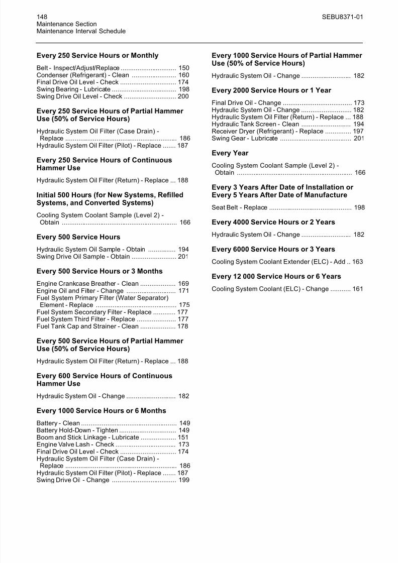
Every 250 Service Hours or Monthly
Belt - Inspect/Adjust/Replace .............................. 150Condenser (Ref rigerant) - Clean ........................ 160Final Drive Oil Level - Check .............................. 174Swing Bearing - Lubricate ................................... 198
Swing Drive Oil Level - Check ............................ 200
Every 250 Service Hours of Partial Hammer Use (50% of Service Hours)
Hydraulic System Oil Filter (Case Drain) -Replace ............................................................. 186
Hydraulic System Oil Filter (Pilot) - Replace ....... 187
Every 250 Service Hours of ContinuousHammer Use
Hydraulic System Oil Filter (Return) - Replace ... 188
Initial 500 Hours (for New Systems, Refi
lledSystems, and Converted Systems)
Cooling System Coolant Sample (Level 2) -Obtain ............................................................... 166
Every 500 Service Hours
Hydraulic System Oil Sample - Obtain ............... 194Swing Drive Oil Sample - Obtain ........................ 201
Every 500 Service Hours or 3 Months
Engine Crankcase Breather - Clean ................... 169Engine Oil and Filter - Change ........................... 171
Fuel System Pr imary Filter (Water Separator)Element - Replace ............................................ 175
Fuel System Secondary Filter - Replace ............ 177Fuel System Third Filter - Replace ..................... 177Fuel Tank Cap and Strainer - Clean ................... 178
Every 500 Service Hours of Partial Hammer Use (50% of Service Hours)
Hydraulic System Oil Filter (Return) - Replace ... 188
Every 600 Service Hours of ContinuousHammer Use
Hydraulic System Oil - Change ........................... 182
Every 1000 Service Hours or 6 Months
Battery - Clean .................................................... 149Battery Hold-Down - Tighten ............................... 149Boom and Stick Linkage - Lubricate ................... 151Engine Valve Lash - Check ................................. 173Final Drive Oil Level - Check .............................. 174Hydraulic System Oil Filter (Case Drain) -
Replace ............................................................. 186Hydraulic System Oil Filter (Pilot) - Replace ....... 187Swing Drive Oil - Change ................................... 199
Every 1000 Service Hours of Partial Hammer Use (50% of Ser vice Hours)
Hydraulic System Oil - Change ........................... 182
Every 2000 Service Hours or 1 Year
Final Drive Oil - Change ..................................... 173Hydraulic System Oil - Change ........................... 182Hydraulic System Oil Filter (Return) - Replace ... 188Hydraulic Tank Screen - Clean ........................... 194Receiver Dryer (Refrigerant) - Replace .............. 197Swing Gear - Lubricate ....................................... 201
Every Year
Cooling System Coolant Sample (Level 2) -Obtain ............................................................... 166
Every 3 Years Af ter Date of Installation or
Every 5 Years Af ter Date of ManufactureSeat Belt - Replace ............................................. 198
Every 4000 Ser vice Hours or 2 Years
Hydraulic System Oil - Change ........................... 182
Every 6000 Ser vice Hours or 3 Years
Cooling System Coolant Extender (ELC) - Add .. 163
Every 12 000 Ser vice Hours or 6 Years
Cooling System Coolant (ELC) - Change ........... 161

8/16/2019 manual mantenimiento excavadora 320d
http://slidepdf.com/reader/full/manual-mantenimiento-excavadora-320d 5/62
SEBU8371-01 149Maintenance Section
Air Conditioner/Cab Heater Filter (Recirculation) - Inspect/Replace
i02459073
Air Conditioner/Cab Heater Filter (Recir culation) -Inspect/Replace
SMCS Code: 1054-040-A/C; 1054-510-A/C
NOTICE An air recirculation filter element plugged with dust willresult in decreased performance and service life to theair conditioner or cab heater.
To prevent decreased performance, clean the filter el-ement, as required.
g01100988Illustration 223
The air conditioner fi
lter is located on the lower leftside of the cab behind the seat.
1. Slide the operator seat forward.
2. Slide the filter element upward.
3. Tap the air fi lter in order to remove the dirt. Do notuse compressed air to clean the filter.
4. After you clean the fi lter element, inspect the fi lter element. If the fi lter element is damaged or badlycontaminated, use a new filter element. Make surethat the fi lter element is dry.
5. Install the filter element.
i00934864
Battery - Clean
SMCS Code: 1401-070
Clean the battery surface with a clean cloth. Keep theterminals clean and keep the terminals coated withpetroleum jelly. Install the post cover after you coatthe terminal post with petroleum jelly.
i00993589
Battery - Recycle
SMCS Code: 1401-561
Always recycle a battery. Never discard a battery.
Always return used batteries to one of the followinglocations:
• A battery supplier
• An authorized battery collection facility
• Recycling facility
i00934872
Battery Hold-Down - Tighten
SMCS Code: 7257
Tighten the hold-downs for the battery in order toprevent the batteries from moving during machineoperation.
i01913589
Battery or Battery Cable -Inspect/Replace
SMCS Code: 1401-040; 1401-510; 1401-561; 1401;
1402-040; 1402-510
Personal injury can result from battery fumes or explosion.
Batteries give off flammable fumes that can ex-plode. Electrolyte is an acid and can cause per-sonal injury if it contacts the skin or eyes.
Prevent sparks near the batteries. Sparks couldcause vapors to explode. Do not allow jumper ca-
ble ends to contact each other or the engine. Im-proper jumper cable connections can cause an ex-plosion.
Always wear protective glasses when workingwith batteries.
1. Turn the engine start switch key to the OFFposition. Turn all of the switches to the OFFposition.
2. Turn the battery disconnect switch to the OFFposition. Remove the key.

8/16/2019 manual mantenimiento excavadora 320d
http://slidepdf.com/reader/full/manual-mantenimiento-excavadora-320d 6/62
150 SEBU8371-01Maintenance SectionBelt - Inspect/Adjust/Replace
3. Disconnect the negative battery cable at thebattery.
4. Disconnect the positive battery cable at thebattery.
5. Disconnect the battery cables at the batterydisconnect switch. The battery disconnect switchis connected to the machine frame.
6. Make necessary repairs or replace the battery.
7. Connect the battery cable at the battery disconnectswitch.
8. Connect the positive battery cable of the battery.
9. Connect the negative battery cable of the battery.
10. Install the key and turn the battery disconnect
switch to the ON position.
i02360330
Belt - Inspect/Adjust/Replace
SMCS Code: 1357-025; 1357-040; 1357-510;1397-025; 1397-040; 1397-510
g00937676Illustration 224
Your engine is equipped with a water pump, witha fan drive, and with an alternator. Your enginecan also be equipped with an air conditioner belt.For maximum engine performance and maximumutilization of your engine, inspect the belts for wear and for cracking. Check the belt tension. Adjust thebelt tension in order to minimize belt slippage. Beltslippage will decrease the belt life. Belt slippage willalso cause poor performance of the alternator andof any driven equipment.
If new belts are installed, recheck the belt adjustmentafter 30 minutes of operation. If two belts or more arerequired for an application, replace the belts in beltsets. If only one belt of a matched set is replaced, thenew belt will carry more load. This is due to the factthat the older belts are stretched. The additional load
on the new belt could cause the new belt to break.
Water Pump Belt, Fan Drive Belt,and Alternator Belt
g00686313Illustration 225
1. Open the engine hood.
g00937677Illustration 226
2. Apply approximately 98 N (22 lb) force midwaybetween the pulleys.
3. Measure the deflection of the belt. The belt shoulddeflect 10 to 12 mm (0.4 to 0.5 inch).
4. If the deflection is not correct, loosen alternator mounting bolt (1) and bracket bolt (2). Turnadjusting bolt (3) in order to adjust the belt tension.
5. When the adjustment is correct, tighten bolt (1)and bolt (2).
6. Check the deflection of the belt again.

8/16/2019 manual mantenimiento excavadora 320d
http://slidepdf.com/reader/full/manual-mantenimiento-excavadora-320d 7/62
SEBU8371-01 151Maintenance Section
Boom and Stick Linkage - Lubricate
7. If a new belt is installed, run the engine atrated speed for thirty minutes. Check the beltadjustment. Readjust the belt, if necessary.
Air Conditioner Belt (If Equipped)
NOTICEThe V-belt must be tensioned correctly. Failure to ten-sion the belt properly could cause damage to the beltand/or to the air conditioner compressor.
g01162234Illustration 227
(4) Nut(5) Adjusting Bolt
1. Apply approximately 100 N (22 lb) force midwaybetween the pulleys.
2. Measure the deflection of the belt. The belt shoulddeflect 7 to 10 mm (0.3 to 0.4 inch).
3. If the deflection is not correct, loosen nut (4). Turnadjusting bolt (5) in order to adjust the belt tension.
4. When the adjustment is correct, tighten nut (4) toa torque of 38 ± 7 N·m (28 ± 5 lb ft).
5. Check the deflection again.
Note: If a new belt is installed, check the beltadjustment again after 30 minutes of engineoperation at the rated engine speed.
6. Close the engine hood.
i01933858
Boom and Stick Linkage -Lubricate
SMCS Code: 6501-086; 6502-086
Note: Caterpillar recommends the use of 5%molybdenum grease for lubricating the boom,stick and bucket control linkage. Refer to SpecialPublication, SEBU6250, “Caterpillar MachineFluids Recommendations” for more information onmolybdenum grease.
Apply lubricant through all fittings after operationunder water.
Wipe all fittings before you apply lubricant.
g00685797Illustration 228
1. Apply lubricant through the fitting at the base of each boom cylinder.
g00685798Illustration 229
2. The fittings are at the base of the boom. Thefittings can be serviced from the platform on topof the storage box. To lubricate the lower boombearings, apply lubricant through fittings (1) and(2).

8/16/2019 manual mantenimiento excavadora 320d
http://slidepdf.com/reader/full/manual-mantenimiento-excavadora-320d 8/62
152 SEBU8371-01Maintenance SectionBucket Linkage - Inspect/Adjust
3. Apply lubricant through fittings (3) and (4) for theboom cylinder rod.
4. Apply lubricant through fitting (5) for the stickcylinder head.
Note: To ensur e proper lubrication of the lower boom bearings and of the boom cylinder rod endbearings, lubricant should be applied through fittings(1), (2), (3), and (4). Apply lubricant first when theboom is raised and any attachment is suspended.Then apply lubricant when the boom is lowered andthe attachment is rested on the ground with a slightdownward pressure.
g00685799Illustration 230
5. Apply lubricant through fitting (6). Fitting (6) is atthe connection point of the boom and of the stick.
g00685800Illustr ation 231
6. Apply lubricant through fitting (7) on the stickcylinder rod, fitting (8) at the connection point of the boom and of the stick, and fitting (9) at thebucket cylinder head end.
i02168785
Bucket Linkage -Inspect/Adjust
SMCS Code: 6513-025; 6513-040
Unexpected machine movement can cause injuryor death.
To avoid possible machine movement, move thehydraulic lockout control to the locked positionand attach a Special Instruction, SEHS7332, “DoNot Operate” or similar warning tag to the hy-draulic lockout control.
NOTICEImproperly adjusted bucket clearance could causegalling on the contact surfaces of the bucket andstick, resulting in excessive noise and/or damagedO-ring seals.
g00101687Illustration 232
(1) No gap(2) Stick boss(3) Bucket clearance(4) Shims(5) Pin(6) Plate(7) Bolts(8) Washers
(9) Location(10) Flange(11) Bucket boss
The clearance of the bucket control linkage onthis machine can be adjusted by shimming. If thegap between the bucket and the stick becomesexcessive, adjust bucket clearance (3) to 0.5 to 1 mm(.02 to .04 inch).
Two shims of different thickness are used at location(9). The thicknesses of the shims are 0.5 mm(0.02 inch ) and 1.0 mm (0.04 inch).

8/16/2019 manual mantenimiento excavadora 320d
http://slidepdf.com/reader/full/manual-mantenimiento-excavadora-320d 9/62
SEBU8371-01 153Maintenance Section
Bucket Linkage - Lubricate
g00102146Illustration 233
Area for linkage adjustmen t
1. Position the machine on a level surface and lower the bucket to the ground.
2. Slowly operate the swing control lever until stickboss (2) and the bucket boss (11) are in full facecontact at no gap (1). This will help to determinethe total clearance of the connection point of thestick and of the bucket.
3. Place the hydraulic lockout control in the LOCKEDposition and stop the engine.
4. Measure bucket clearance (3), which is theexisting total clearance.
5. Determine the number of shims that need to be
removed from shims (4) by using the followingcalculation:
Subtract 0.5 mm (0.02 inch ) or 1.0 mm (0.04 inch)from bucket clearance (3).
6. Remove the appropriate number of shims atlocation (9) in order to meet the above thickness.Make sure that you use a minimum of three0.5 mm (0.02 inch) shims. To remove the shims,remove bolts (7), washers (8), and plate (6).
7. After the correct number of shims has beenremoved and pin (5) is aligned with the pin
hole, install plate (6), washers (8), and bolts (7).Tighten bolts (7) to a torque of 240 ± 40 N·m(175 ± 30 lb ft).
8. After installation, make sure that bucket clearance(3) is still correct.
i01942324
Bucket Linkage - Lubricate
SMCS Code: 6513-086
Note: Caterpillar recommends the use of 5%molybdenum grease for lubricating the bucketlinkage. Refer to Special Publication, SEBU6250,“Caterpillar Machine Fluids Recommendations” for more information on grease.
Wipe all fittings before you apply lubricant.
g00682908Illustration 234
Note: Completely fill all cavities of the bucket controllinkage with grease when you initially install a bucket.
1. Apply lubricant through fittings for the linkages (1),
(2), (3), and (4).
2. Apply lubricant through fittings for the bucket (5),(6), and (7).
Note: Service the above fittings after you operatethe bucket under water.
i02963002
Bucket Tips - Inspect/Replace(Drive-through System)
SMCS Code: 6805-040; 6805-510
Personal injury or death can result from bucketfalling.
Block the bucket before changing bucket tips or side cutters.

8/16/2019 manual mantenimiento excavadora 320d
http://slidepdf.com/reader/full/manual-mantenimiento-excavadora-320d 10/62
154 SEBU8371-01Maintenance SectionBucket Tips - Inspect/Replace
Bucket Tips
Note: In order to maximize the life of the bucket tipand the penetration of the bucket tip, the bucket tipcan be rotated.
g01055179
Illustration 235 Acceptabl e wear
g01055196Illustration 236
Replace this bucket tip.
Check the bucket tips for wear. If the bucket tip has ahole, replace the bucket tip.
Removal Procedure
Retainer pin, when struck with force, can fly outand cause injury to nearby people.
Make sure the area is clear of people when drivingretainer pins.
To avoid injury to your eyes, wear protectiveglasses when striking a retainer pin.
g01053737Illustration 237
(1) Bucket tip(2) Retainer (3) Adapter
Note: Retainers are often damaged during theremoval process. Caterpillar recommends theinstallation of a new retainer when bucket tips arerotated or replaced.
g01054386Illustration 238
Internal view
1. Use a hammer and a punch in order to drive outthe retainer. The retainer can be removed fromthe top of the bucket tip or from the bottom of thebucket tip.
2. Remove the bucket tip from the adapter with a
slight counterclockwise rotation.
Installation Procedure
1. Clean the adapter, if necessary.
2. Install the new bucket tip or the rotated bucket tiponto the adapter with a slight clockwise rotation.
8/16/2019 manual mantenimiento excavadora 320d
http://slidepdf.com/reader/full/manual-mantenimiento-excavadora-320d 11/62
SEBU8371-01 155Maintenance Section
Bucket Tips - Inspect/Replace
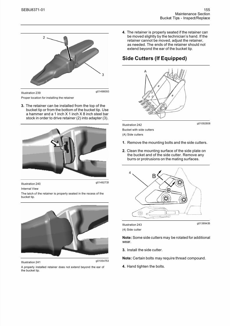
g01498093Illustration 239
Proper location for installing the retainer
3. The retainer can be installed from the top of thebucket tip or from the bottom of the bucket tip. Use
a hammer and a 1 inch X 1 inch X 8 inch steel bar stock in order to drive retainer (2) into adapter (3).
g01492733Illustration 240
Internal View
The latch of the retainer is properly seated in the recess of thebucket tip.
g01054753Illustration 241
A properly installed retainer does not extend beyond the ear of the bucket tip.
4. The retainer is properly seated if the retainer canbe moved slightly by the technician’s hand. If theretainer cannot be moved, adjust the retainer,as needed. The ends of the retainer should notextend beyond the ear of the bucket tip.
Side Cutters (If Equipped)
g01092808Illustration 242
Bucket with side cutters
(A) Side cutters
1. Remove the mounting bolts and the side cutters.
2. Clean the mounting surface of the side plate onthe bucket and of the side cutter. Remove anyburrs or protrusions on the mating surfaces.
g01389435Illustration 243
(4) Side cutter
Note: Some side cutters may be rotated for additionalwear.
3. Install the side cutter.
Note: Certain bolts may require thread compound.
4. Hand tighten the bolts.
8/16/2019 manual mantenimiento excavadora 320d
http://slidepdf.com/reader/full/manual-mantenimiento-excavadora-320d 12/62
156 SEBU8371-01Maintenance SectionBucket Tips - Inspect/Replace
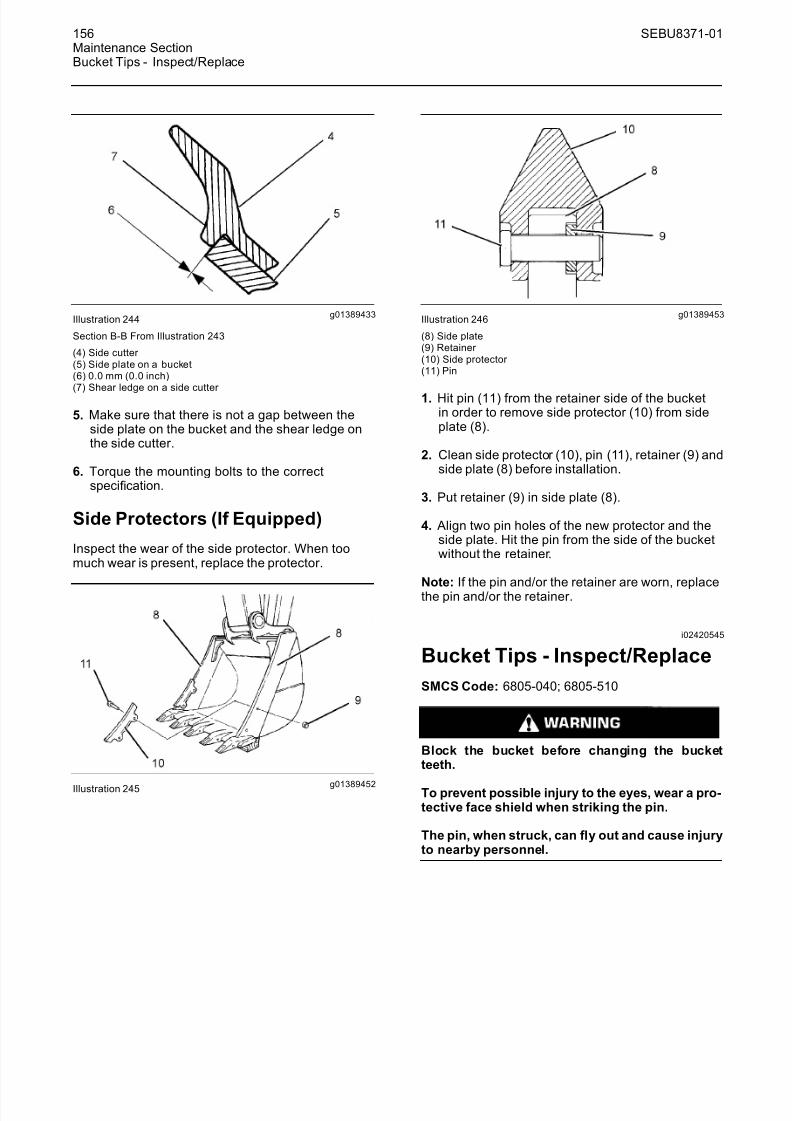
g01389433Illustration 244
Section B-B From Illustration 243
(4) Side cutter (5) Side plate on a bucket(6) 0.0 mm (0.0 inch)
(7) Shear ledge on a side cutter
5. Make sure that there is not a gap between theside plate on the bucket and the shear ledge onthe side cutter.
6. Torque the mounting bolts to the correctspecification.
Side Protectors (If Equipped)
Inspect the wear of the side protector. When toomuch wear is present, replace the protector.
g01389452Illustration 245
g01389453Illustration 246
(8) Side plate(9) Retainer (10) Side protector (11) Pin
1. Hit pin (11) from the retainer side of the bucketin order to remove side protector (10) from sideplate (8).
2. Clean side protector (10), pin (11), retainer (9) andside plate (8) before installation.
3. Put retainer (9) in side plate (8).
4. Align two pin holes of the new protector and theside plate. Hit the pin from the side of the bucketwithout the retainer.
Note: If the pin and/or the retainer are worn, replacethe pin and/or the retainer.
i02420545
Bucket Tips - Inspect/Replace
SMCS Code: 6805-040; 6805-510
Block the bucket before changing the bucketteeth.
To prevent possible injury to the eyes, wear a pro-tective face shield when striking the pin.
The pin, when struck, can fly out and cause injuryto nearby personnel.

8/16/2019 manual mantenimiento excavadora 320d
http://slidepdf.com/reader/full/manual-mantenimiento-excavadora-320d 13/62
SEBU8371-01 157Maintenance Section
Bucket Tips - Inspect/Replace
Bucket Tips
g00101352Illustration 247
(1) Usable(2) Replace this bucket tip.(3) Overworn
Check the bucket tips for wear. If the bucket tip has ahole, replace the bucket tip.
1. Remove the pin from the bucket tip. The pin canbe removed by one of the following methods.
• Use a hammer and a punch from the retainer side of the bucket to drive out the pin.
• Use a Pin-Master. Follow Step 1.a through Step1.c for the procedure.
g00590670Illustration 248
(4) Back of Pin-Master (5) Extractor
a. Place the Pin-Master on the bucket tip.
b. Align extr actor (5) with the pin.
c. Strike the Pin-Master at the back of the tool (4)and remove the pin.
Note: Discard the old pin and the retainer assembly.When you change tips, use a new pin and a newretainer assembly. Refer to the appropriate partsmanual for your machine.
g01194448Illustration 249
(6) Retainer assembly(7) Adapter
2. Clean the adapter and the pin.
3. Fit retainer assembly (6) into the counterbore thatis in the side of adapter (7). Make sure that theface of the retainer assembly with the marking“OUTSIDE” is visible.
g00101359Illustration 250
4. Install the new bucket tip onto the adapter.
Note: The bucket tips can be rotated by 180 degreesin order to allow the tip to wear evenly. You may alsomove the tips from the outside teeth to the insideteeth. Check the tips often. If wear is present on the
tips, rotate the tips. The outside teeth generate themost wear .
5. Drive the pin through the bucket tip. The pin canbe installed by using one of the following methods:
• From the same side of the retainer, drive the pinthrough the bucket tip, the retainer assembly,and the adapter.
• Use a Pin-Master. Follow Step 5.a through Step5.e for the procedure.
8/16/2019 manual mantenimiento excavadora 320d
http://slidepdf.com/reader/full/manual-mantenimiento-excavadora-320d 14/62
158 SEBU8371-01Maintenance SectionBucket Tips - Inspect/Replace
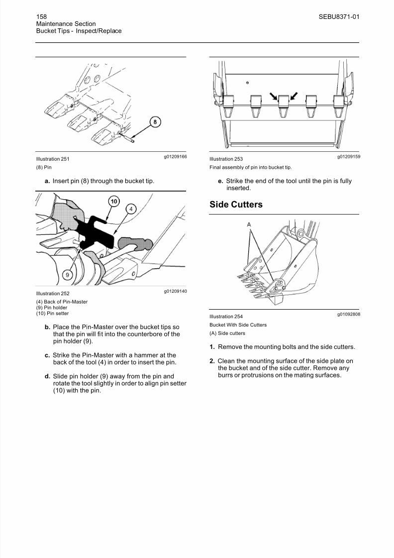
g01209166Illustration 251
(8) Pin
a. Insert pin (8) through the bucket tip.
g01209140Illustration 252
(4) Back of Pin-Master (9) Pin holder (10) Pin setter
b. Place the Pin-Master over the bucket tips sothat the pin will fit into the counterbore of thepin holder (9).
c. Strike the Pin-Master with a hammer at theback of the tool (4) in order to insert the pin.
d. Slide pin holder (9) away from the pin androtate the tool slightly in order to align pin setter
(10) with the pin.
g01209159Illustration 253
Final assembly of pin into bucket tip.
e. Strike the end of the tool until the pin is fullyinserted.
Side Cutters
g01092808Illustration 254
Bucket With Side Cutters
(A) Side cutters
1. Remove the mounting bolts and the side cutters.
2. Clean the mounting surface of the side plate onthe bucket and of the side cutter. Remove anyburrs or protrusions on the mating surfaces.

8/16/2019 manual mantenimiento excavadora 320d
http://slidepdf.com/reader/full/manual-mantenimiento-excavadora-320d 15/62
SEBU8371-01 159Maintenance Section
Bucket Tips - Inspect/Replace
g01092810Illustration 255
(A) Side cutter
Note: Some side cutters may be rotated for additionalwear.
3. Install the side cutter.
Note: Certain bolts may require thread compound.
4. Hand tighten the bolts.
g01092812Illustration 256
Section B-B From Illustration 255
(A) Side cutter (C) Shear ledge on a side cutter (D) Side plate on a bucket(E) 0.0 mm (0.0 inch)
5. Make sure that there is not a gap between theside plate on the bucket and the shear ledge onthe side cutter.
6. Torque the mounting bolts to the correctspecification.
Side Protectors
Inspect the wear of the side protector. When toomuch wear is present, replace the protector.
g00851494Illustration 257
g00851496Illustration 258
(11) Side protector (12) Pin(13) Retainer (14) side plate
1. Hit pin (12) from the retainer side of the bucketin order to remove side protector (11) from sideplate (14).
2. Clean side protector (11), pin (12), retainer (13)and side plate (14) before installation.
3. Put retainer (13) in side plate (14).
4. Align two pin holes of the new protector and theside plate. Hit the pin from the side of the bucketwithout the retainer.
Note: If the pin and/or the retainer are worn, replacethe pin and/or the retainer.

8/16/2019 manual mantenimiento excavadora 320d
http://slidepdf.com/reader/full/manual-mantenimiento-excavadora-320d 16/62
160 SEBU8371-01Maintenance SectionCab Air Filter (Fresh Air) - Clean/Replace
i01547055
Cab Air Filter (Fresh Air) -Clean/Replace
SMCS Code: 7342-070; 7342-510
g00730030Illustration 259
(1) Bolt(2) Filter cover
The cab air filter is behind the cab.
1. Loosen bolt (1) and open fi lter cover (2).
g00730032Illustration 260
(2) Filter cover (3) Air filter
2. Remove air fi lter (3) from fi lter cover (2).
3. Clean the air filter with a maximum of 200 kPa(30 psi) pressure air.
4. After you clean the air filter, inspect the air fi lter.If the air fi lter is damaged or badly contaminated,use a new air filter.
5. Install the air filter and the filter cover.
Note: Make sure that the arrow on top of the air fi lter is facing forward.
i02465602
Circuit Breakers - Reset
SMCS Code: 1420-529
Open the access door on the left side of the machine.
g01120975Illustration 261
Main Breaker (1) – This circuit breaker is designedto protect the electrical system. The circuit breaker has a capacity of 80 Amp.
Air Inlet Heater Circuit (2) – This circuit breaker isdesigned to protect the air inlet heater. The circuitbreaker has a capacity of 120 Amp.
Alternator Circuit (3) – This circuit breaker isdesigned to protect the alternator. If the batteries are
installed with reversed polarity, the circuit breaker would prevent the alternator from damaging therectifier. The circuit breaker has a capacity of 60 Amp.
Circuit Breaker Reset – Push in the button in order to reset the circuit breaker. If the electrical system isworking properly, the button will remain depressed.If the button does not remain depressed, check theappropriate electrical circuit. Repair the electricalcircuit, if necessary.
i01041005
Condenser (Refrigerant) -Clean
SMCS Code: 1805-070
NOTICEIf excessively dirty, clean condenser with a brush. Toprevent damage or bending of the fins, do not use astiff brush.
Repair the fins if found defective.

8/16/2019 manual mantenimiento excavadora 320d
http://slidepdf.com/reader/full/manual-mantenimiento-excavadora-320d 17/62
SEBU8371-01 161Maintenance Section
Cooling System Coolant (ELC) - Change
g00102191Illustration 262
1. Open the access door on the left side of themachine.
g00537515
Illustration 263Typical example
2. Inspect the condenser for debris. Clean thecondenser, if necessary.
3. Use clean water to wash off all dust and dirt fromthe condenser.
4. Close the access door.
i02582005
Cooling System Coolant (ELC)- Change
SMCS Code: 1350-044
Personal injury can result from hot coolant, steamand alkali.
At operating temperature, engine coolant is hotand under pressure. The radiator and all linesto heaters or the engine contain hot coolant or steam. Any contact can cause severe burns.
Remove cooling system pressure cap slowly torelieve pressure only when engine is stopped and
cooling system pressure cap is cool enough totouch with your bare hand.
Do not attempt to tighten hose connections whenthe coolant is hot, the hose can come off causingburns.
Cooling System Coolant Additive contains alkali.Avoid contact with skin and eyes.
NOTICEDo not change the coolant until you read and under-stand the cooling system information in Special Pub-
lication, SEBU6250, “Caterpillar Machine Fluids Rec-ommendations”.
Failure to do so could result in damage to the coolingsystem components.
NOTICEMixing ELC with other products will reduce the effec-tiveness of the coolant.
This could r esult in damage to cooling system compo-nents.
If Caterpillar products are not available and com-mercial products must be used, make sure theyhave passed the Caterpillar EC-1 specification for pre-mixed or concentrate coolants and Caterpillar Extender.
Note: This machine was filled at the factory withCaterpillar Extended Life Coolant.
If the coolant in the machine is changed to ExtendedLife Coolant from another type of coolant, see SpecialPublication, SEBU6250, “Caterpillar Machine FluidsRecommendations”.

8/16/2019 manual mantenimiento excavadora 320d
http://slidepdf.com/reader/full/manual-mantenimiento-excavadora-320d 18/62
162 SEBU8371-01Maintenance SectionCooling System Coolant (ELC) - Change
1. Unlatch the engine hood and raise the enginehood.
g00544510Illustration 264
2. Slowly loosen the pressure cap that is on the
radiator in order to release pressure from thecooling system.
3. Remove the pressure cap.
g00544378Illustration 265
Note: Refer to Operation and Maintenance Manual,“General Hazard Information” for information thatpertains to containing fluid spillage.
4. Remove the access cover that is underneath theradiator.
5. Open the drain valve and allow the coolant todrain into a suitable container. The drain valve islocated on the bottom of the radiator.
6. Flush the cooling system. Follow Step 6.a throughStep 6.h in order to properly flush the coolingsystem.
a. Close the drain valve.
b. Fill the cooling system with clean water.
c. Install the pressure cap.
d. Start the engine and run the engine until theengine reaches operating temperature.
e. Stop the engine and allow the engine to cool.
f. Loosen the pressure cap slowly in order to
relieve any pr essure in the cooling system.
g. Open the drain valve that is underneath theradiator and allow the coolant to drain into asuitable container.
h. Flush the radiator with clean water until thedraining water is transparent.
7. Close the drain valve and install the access cover underneath the radiator.
8. Add the Extended Life Coolant. Refer to thefollowing topics:
• Special Publication, SEBU6250, “Caterpillar Machine Fluids Recommendations”
• Operation and Maintenance Manual, “Capacities(Refill)”
9. Start the engine. Operate the engine withoutthe cooling system pressure cap until the water temperature regulator opens and the coolant levelstabilizes.
10. Maintain the coolant level within 13 mm (.5 inches)of the bottom of the filler pipe.
11. Inspect the gasket of the cooling system pressurecap. If the gasket is damaged, replace thepressure cap.
12. Install the cooling system pressure cap.
13. Stop the engine.
14. Open the left access door.
g00545226Illustration 266
(1) “FULL”(2) “LOW”

8/16/2019 manual mantenimiento excavadora 320d
http://slidepdf.com/reader/full/manual-mantenimiento-excavadora-320d 19/62
SEBU8371-01 163Maintenance Section
Cooling System Coolant Extender (ELC) - Add
15. Check the coolant reservoir. Maintain the coolantlevel between “FULL” mark (1) and “LOW” mark(2).
16. If additional coolant is necessary, remove thereservoir cap and add the appropriate coolant
solution.
17. Install the reservoir cap.
18. Close the engine hood and latch the engine hood.Close the left access door.
i02586600
Cooling System CoolantExtender (ELC) - Add
SMCS Code: 1352; 1353; 1395
Personal injury can result from hot coolant, steamand alkali.
At operating temperature, engine coolant is hotand under pressure. The radiator and all linesto heaters or the engine contain hot coolant or steam. Any contact can cause severe burns.
Remove cooling system pressure cap slowly torelieve pressure only when engine is stopped and
cooling system pressure cap is cool enough totouch with your bare hand.
Do not attempt to tighten hose connections whenthe coolant is hot, the hose can come off causingburns.
Cooling System Coolant Additive contains alkali.Avoid contact with skin and eyes.
Use Caterpillar Extended Life Coolant (ELC) whenyou add coolant to the cooling system. See SpecialPublication, SEBU6250, “Caterpillar MachineFluids Recommendations” for all cooling system
requirements.
Use a Coolant Conditioner Test Kit in order to checkthe concentration of the coolant.
NOTICEMixing ELC with other products will reduce the effec-tiveness of the coolant.
This could result in damage to cooling system compo-
nents.
If Caterpillar products are not available and com-mercial products must be used, make sure theyhave passed the Caterpillar EC-1 specification for pre-mixed or concentrate coolants and Caterpillar Extender.
Note: This machine was filled at the factory withCaterpillar Extended Life Coolant.
1. Park the machine on level ground.
2. Stop the engine.
3. Unlatch the engine hood and raise the enginehood.
g00544510Illustration 267
4. Make sure that the cooling system has cooleddown. Loosen the cooling system pressurecap slowly in order to relieve system pressure.Remove the pressure cap.
Note: Refer to Operation and Maintenance Manual,“General Hazard Information” for information on
containing fl
uid spillage.
5. It may be necessary to drain some coolant fromthe radiator so that Caterpillar Extender can beadded to the cooling system.
Note: Always discard drained fluids according tolocal regulations.
6. Add Caterpillar Extended Life Coolant (ELC) tothe cooling system. Refer to the following topicsfor the proper amount of Caterpillar Extender:

8/16/2019 manual mantenimiento excavadora 320d
http://slidepdf.com/reader/full/manual-mantenimiento-excavadora-320d 20/62
164 SEBU8371-01Maintenance SectionCooling System Coolant Level - Check
• Special Publication, SEBU6250, “Caterpillar Machine Fluids Recommendations”
• Operation and Maintenance Manual, “Capacities(Refill)”
7. Inspect the gasket of the cooling system pressurecap. If the gasket is damaged, replace thepressure cap.
8. Install the cooling system pressure cap.
9. Close the engine hood and latch the engine hood.
i02580035
Cooling System Coolant Level- Check
SMCS Code: 1350-040; 1350-535-FLV;1395-535-FLV
Personal injury can result from hot coolant, steamand alkali.
At operating temperature, engine coolant is hotand under pressure. The radiator and all linesto heaters or the engine contain hot coolant or steam. Any contact can cause severe burns.
Remove cooling system pressure cap slowly torelieve pressure only when engine is stopped andcooling system pressure cap is cool enough totouch with your bare hand.
Do not attempt to tighten hose connections whenthe coolant is hot, the hose can come off causingburns.
Cooling System Coolant Additive contains alkali.Avoid contact with skin and eyes.
1. Open the left rear access door.
g00545226Illustration 268
(1) “FULL” level(2) “LOW” level
2. Check the coolant level of the coolant reservoir.
Maintain the coolant level between the “FULL”mark and the “LOW” mark. If the coolant reservoir is empty, follow Steps 2.a through 2.i.
a. Unlatch the engine hood and raise the enginehood.
g00544510Illustration 269
b. Slowly loosen the cooling system pressure capin order to relieve system pressure. Removethe pressure cap.
Note: Refer to Operation and Maintenance Manual,
“General Hazard Information” for information oncontaining fluid spillage.
c. Add the appropriate coolant solution to thecooling system. Refer to the following topics:
• Special Publication, SEBU6250, “Caterpillar Machine Fluids Recommendations”
• Operation and Maintenance Manual,“Capacities (Refill)”

8/16/2019 manual mantenimiento excavadora 320d
http://slidepdf.com/reader/full/manual-mantenimiento-excavadora-320d 21/62
SEBU8371-01 165Maintenance Section
Cooling System Coolant Sample (Level 1) - Obtain
d. Start the engine. Operate the engine withoutthe cooling system pressure cap until the water temperature regulator opens and the coolantlevel stabilizes.
e. Maintain the coolant level within 13 mm
(0.5 inch) of the bottom of the fi ller pipe.
f. Inspect the condition of the gasket on thepressure cap. If the gasket is damaged, replacethe pressure cap.
g. Install the cooling system pressure cap.
h. Stop the engine.
i. Close the engine hood and latch the enginehood.
Note: Refer to Operation and Maintenance Manual,
“General Hazard Information” for information oncontaining fluid spillage.
3. If additional coolant is necessary, remove thereservoir cap and add the appropriate coolantsolution.
4. Install the reservoir cap.
5. Close the left access door.
i02250847
Cooling System CoolantSample (Level 1) - Obtain
SMCS Code: 1395-008; 1395-554; 7542
Note: It is not necessary to obtain a CoolantSample (Level 1) if the cooling system is filledwith Cat ELC (Extended Life Coolant). Coolingsystems that are filled with Cat ELC should havea Coolant Sample (Level 2) that is obtained atthe recommended interval that is stated in theMaintenance Interval Schedule.
Note: Obtain a Coolant Sample (Level 1) if the
cooling system is filled with any other coolantinstead of Cat ELC. This includes the followingtypes of coolants.
• Commercial long life coolants that meet theCaterpillar Engine Coolant Specification -1(Caterpillar EC-1)
• Cat Diesel Engine Antifreeze/Coolant (DEAC)
• Commercial heavy-duty coolant/antifreeze
NOTICE Always use a designated pump for oil sampling, anduse a separate designated pump for coolant sampling.Using the same pump for both types of samples maycontaminate the samples that are being drawn. This
contaminate may cause a false analysis and an incor-rect interpretation that could lead to concerns by bothdealers and customers.
Note: Level 1 results may indicate a need for Level 2 Analysis.
NOTICECare must be taken to ensure that fluids are containedduring performance of inspection, maintenance, test-ing, adjusting andrepair of the product. Be prepared tocollect the fluid with suitable containers before open-ing any compartment or disassembling any compo-
nent containing fluids.
Refer to Special Publication, NENG2500, “Caterpillar Tools and Shop Products Guide” for tools and suppliessuitable to collect and contain fluids on Caterpillar products.
Dispose of all fluids according to local regulations andmandates.
g00811362Illustration 270
A typical example is shown.
Obtain the sample of the coolant as close as possibleto the recommended sampling interval. In order to receive the full effect of S·O·S analysis, youmust establish a consistent trend of data. In order to establish a pertinent history of data, performconsistent samplings that are evenly spaced.Supplies for collecting samples can be obtained fromyour Caterpillar dealer.
Use the following guidelines for proper sampling of the coolant:

8/16/2019 manual mantenimiento excavadora 320d
http://slidepdf.com/reader/full/manual-mantenimiento-excavadora-320d 22/62
166 SEBU8371-01Maintenance SectionCooling System Coolant Sample (Level 2) - Obtain
• Complete the information on the label for thesampling bottle before you begin to take thesamples.
• Keep the unused sampling bottles stored in plasticbags.
• Obtain coolant samples directly from the coolantsample port. You should not obtain the samplesfrom any other location.
• Keep the lids on empty sampling bottles until youare ready to collect the sample.
• Place the sample in the mailing tube immediatelyafter obtaining the sample in order to avoidcontamination.
• Never collect samples from expansion bottles.
• Never collect samples from the drain for a system.
Submit the sample for Level 1 analysis.
For additional information about coolant analysis, seeSpecial Publication, SEBU6250, “Caterpillar MachineFluids Recommendations” or consult your Caterpillar dealer.
i02049802
Cooling System CoolantSample (Level 2) - Obtain
SMCS Code: 1395-008; 1395-554; 7542
Reference: Refer to Operation and MaintenanceManual, “Cooling System Coolant Sample (Level 1)- Obtain” for the guidelines for proper sampling of the coolant.
Obtain the sample of the coolant as close as possibleto the recommended sampling interval. Suppliesfor collecting samples can be obtained from your Caterpillar dealer.
Submit the sample for Level 2 analysis.
Reference: For additional information about coolantanalysis, refer to Special Publication, SEBU6250,“Caterpillar Machine Fluids Recommendations” or consult your Caterpillar dealer.
i02530911
Engine Air Filter PrimaryElement - Clean/Replace
SMCS Code: 1054-070; 1054-510
If a warning and a pictograph is displayed on themessage display or if the exhaust is black, check theprimary filter .
1. Open both access doors on the left side of themachine.
g01266485Illustration 271
2. Squeeze the outlet tube (1) slightly in order topurge the dirt from the outlet tube.
g01266486Illustration 272
3. Loosen the cover latches (2) and remove the air cleaner cover.
8/16/2019 manual mantenimiento excavadora 320d
http://slidepdf.com/reader/full/manual-mantenimiento-excavadora-320d 23/62
SEBU8371-01 167Maintenance Section
Engine Air Filter Primary Element - Clean/Replace
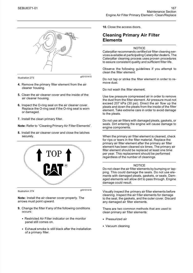
g00101415Illustration 273
4. Remove the primary filter element from the air cleaner housing.
5. Clean the air cleaner cover and the inside of theair cleaner housing.
6. Inspect the O-ring seal on the air cleaner cover.Replace the O-ring seal if the O-ring seal is wornor damaged.
7. Install the clean primary filter.
Note: Refer to “Cleaning Primary Air Filter Elements”.
8. Install the air cleaner cover and close the latchessecurely.
g00101416Illustration 274
Note: Install the air cleaner cover properly. Thearrows must point upward.
9. Change the filter if any of the following conditionsoccurs:
• Restricted Air Filter indicator on the monitor panel still comes on.
• Exhaust smoke is still black after the installationof a primary filter.
10. Close the access doors.
Cleaning Primary Air Filter Elements
NOTICECaterpillar recommends certified air filter cleaning ser-vices available at participating Caterpillar dealers. TheCaterpillar cleaning process uses proven proceduresto assure consistent quality and suf ficient filter life.
Observe the following guidelines if you attempt toclean the filter element:
Do not tap or strike the filter element in order to re-move dust.
Do not wash the filter element.
Use low pressure compressed air in order to removethe dust from the filter element. Air pressure must notexceed 207 kPa (30 psi). Direct the air flow up thepleats and down the pleats from the inside of the filter element. Take extreme care in order to avoid damageto the pleats.
Do not use air filters with damaged pleats, gaskets, or seals. Dirt entering the engine will cause damage toengine components.
When the primary air fi lter element is cleaned, checkfor rips or tears in the filter material. Replace the
primary air filter element after the primary air filter element has been cleaned six times. The primary air filter element should be replaced at least one timeper year. This replacement should be performedregardless of the number of cleanings.
NOTICEDo not clean the air filter elements by bumping or tap-ping. This could damage the seals. Do not use ele-ments with damaged pleats, gaskets, or seals. Dam-aged elements will allow dirt to pass through. Enginedamage could result.
Visually inspect the primary air fi lter elements beforecleaning. Inspect the air fi lter elements for damageto the seal, the gaskets, and the outer cover. Discardany damaged air filter elements.
There are two common methods that are used toclean primary air filter elements:
• Pressur ized air
• Vacuum cleaning
8/16/2019 manual mantenimiento excavadora 320d
http://slidepdf.com/reader/full/manual-mantenimiento-excavadora-320d 24/62
168 SEBU8371-01Maintenance SectionEngine Air Filter Primary Element - Clean/Replace
Pressurized Air
Pressurized air can be used to clean primary air fi lter elements that have not been cleaned more than twotimes. Pressurized air will not remove deposits of carbon and oil. Use fi ltered, dry air with a maximum
pressure of 207 kPa (30 psi).
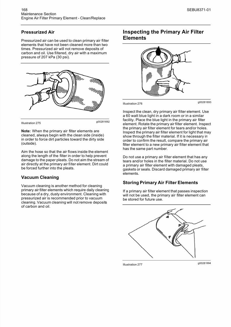
g00281692Illustration 275
Note: When the primary air filter elements arecleaned, always begin with the clean side (inside)in order to force dirt particles toward the dirty side(outside).
Aim the hose so that the air flows inside the elementalong the length of the filter in order to help preventdamage to the paper pleats. Do not aim the stream of air directly at the primary air fi lter element. Dirt couldbe forced further into the pleats.
Vacuum Cleaning
Vacuum cleaning is another method for cleaningprimary air filter elements which require daily cleaningbecause of a dry, dusty environment. Cleaning withpressurized air is recommended prior to vacuumcleaning. Vacuum cleaning will not remove depositsof carbon and oil.
Inspecting the Primary Air Filter Elements
g00281693Illustration 276
Inspect the clean, dry primary air fi lter element. Use
a 60 watt blue light in a dark room or in a similar facility. Place the blue light in the primary air filter element. Rotate the primary air filter element. Inspectthe primary air fi lter element for tears and/or holes.Inspect the primary air filter element for light that mayshow through the fi lter material. If it is necessary inorder to confirm the result, compare the primary air filter element to a new primary air fi lter element thathas the same part number.
Do not use a primary air fi lter element that has anytears and/or holes in the filter material. Do not usea primary air filter element with damaged pleats,gaskets or seals. Discard damaged primary air fi lter elements.
Storing Primary Air Filter Elements
If a primary air filter element that passes inspectionwill not be used, the primary air filter element canbe stored for future use.
g00281694Illustration 277

8/16/2019 manual mantenimiento excavadora 320d
http://slidepdf.com/reader/full/manual-mantenimiento-excavadora-320d 25/62
SEBU8371-01 169Maintenance Section
Engine Air Filter Secondary Element - Replace
Do not use paint, a waterproof cover, or plastic as aprotective covering for storage. An air flow restrictionmay result. To protect against dirt and damage, wrapthe primary air fi lter elements in Volatile CorrosionInhibited (VCI) paper.
Place the primary air filter element into a box for storage. For identification, mark the outside of thebox and mark the primary air filter element. Includethe following information:
• Date of cleaning
• Number of cleanings
Store the box in a dry location.
i01430699
Engine Air Filter SecondaryElement - Replace
SMCS Code: 1054-510
NOTICE Always replace the secondary filter element. Never at-tempt to reuse the secondary filter element by clean-ing the element.
When the primary filter element is replaced, the sec-ondary filter element should be replaced.
The secondary filter element should also be replacedif the air filter restriction warning appears on the mes-sage display after the installation of a clean primaryfilter element or if exhaust smoke is still black.
1. Open the access door on the front left side of themachine.
2. See Operation and Maintenance Manual, “Engine Air Filter Primary Element - Clean/Replace”.Remove the air cleaner cover from the air cleaner housing. Remove the primary fi lter element fromthe air cleaner housing.
g00101451Illustration 278
3. Remove the secondary filter element.
4. Cover the air inlet opening. Clean the inside of
the air cleaner housing.
5. Remove the cover from the air inlet opening.
6. Install the new secondary filter element.
7. Install the primary filter element.
8. Install the air cleaner cover and close the latchessecurely.
9. Close the access door.
i01584904
Engine Crankcase Breather -Clean
SMCS Code: 1317-070-DJ
1. Open the engine hood.
g00824179Illustration 279
2. Loosen hose clamp (2) and disconnect outlet hose(1) from breather (3).

8/16/2019 manual mantenimiento excavadora 320d
http://slidepdf.com/reader/full/manual-mantenimiento-excavadora-320d 26/62
170 SEBU8371-01Maintenance SectionEngine Oil Level - Check
3. Remove breather (3) and O-ring seal (4).
4. Wash breather (3) in clean, nonflammable solvent.
5. Inspect O-ring seal (4). If the seal is damaged,install a new seal.
6. Install O-ring seal (4) and clean breather (3).
7. Slide outlet hose (1) on breather (3). Tighten hoseclamp (2).
8. Close the engine hood.
i02865726
Engine Oil Level - Check
SMCS Code: 1000-535
Hot oil and hot components can cause personalinjury. Do not allow hot oil or hot components tocontact skin.
NOTICEDo not over fill the crankcase. Engine damage can re-sult.
Note: This machine is equipped with both anautomated function for checking fluid levels and
a dipstick. Refer to Operation and MaintenanceManual, “Monitoring System” regarding theautomated system. If the machine is on an incline or the engine has been stopped only for a short time,then the engine oil does not return to the crankcaseand the fluid level cannot be properly checked byeither method. Park the machine on level ground andcheck the oil level after the engine has been stoppedfor at least 30 minutes.
Check the oil level while the engine is stopped. Donot check the oil level while the engine is running.
1. Open the hood.
g01365881Illustration 280
2. Remove the dipstick (1). Wipe the oil off thedipstick (1) and insert the dipstick (1).
g00824185
Illustration 281
3. Remove the dipstick (1) and check the dipstick(1). The oil level should be between the “H” markand the “L” mark.
NOTICEOperating your engine when the oil level is above the“H” mark could cause the crankshaft to dip into the oil.This could lead to excessively high oil temperatureswhich can reduce the lubricating characteristics of theoil, lead to bearing damage, and could result in loss of engine power.
8/16/2019 manual mantenimiento excavadora 320d
http://slidepdf.com/reader/full/manual-mantenimiento-excavadora-320d 27/62
SEBU8371-01 171Maintenance Section
Engine Oil Sample - Obtain
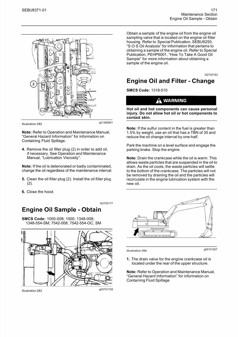
g01365841Illustration 282
Note: Refer to Operation and Maintenance Manual,“General Hazard Information” for information onContaining Fluid Spillage.
4. Remove the oil filler plug (2) in order to add oil,if necessary. See Operation and MaintenanceManual, “Lubrication Viscosity”.
Note: If the oil is deteriorated or badly contaminated,change the oil regardless of the maintenance interval.
5. Clean the oil filler plug (2). Install the oil fi ller plug(2).
6. Close the hood.
i02720177
Engine Oil Sample - Obtain
SMCS Code: 1000-008; 1000; 1348-008;1348-554-SM; 7542-008; 7542-554-OC, SM
g00751728Illustration 283
Obtain a sample of the engine oil from the engine oilsampling valve that is located on the engine oil filter housing. Refer to Special Publication, SEBU6250,“S·O·S Oil Analysis” for information that pertains toobtaining a sample of the engine oil. Refer to SpecialPublication, PEHP6001, “How To Take A Good Oil
Sample” for more information about obtaining asample of the engine oil.
i02720183
Engine Oil and Filter - Change
SMCS Code: 1318-510
Hot oil and hot components can cause personalinjury. Do not allow hot oil or hot components to
contact skin.
Note: If the sulfur content in the fuel is greater than1.5% by weight, use an oil that has a TBN of 30 andreduce the oil change interval by one-half.
Park the machine on a level surface and engage theparking brake. Stop the engine.
Note: Drain the crankcase while the oil is warm. Thisallows waste particles that are suspended in the oil todrain. As the oil cools, the waste particles will settleto the bottom of the crankcase. The particles will not
be removed by draining the oil and the particles willrecirculate in the engine lubrication system with thenew oil.
g00101627Illustration 284
1. The drain valve for the engine crankcase oil islocated under the rear of the upper structure.
Note: Refer to Operation and Maintenance Manual,“General Hazard Information” for information onContaining Fluid Spillage.

8/16/2019 manual mantenimiento excavadora 320d
http://slidepdf.com/reader/full/manual-mantenimiento-excavadora-320d 28/62
172 SEBU8371-01Maintenance SectionEngine Oil and Filter - Change
g00937651Illustration 285
2. Open the crankcase drain valve. Allow the oil todrain into a suitable container.
Note: Discard any drained fluids according to localregulations.
3. Close the drain valve.
4. Open the access door on the right side of themachine.
g01365879Illustration 286
5. Remove the oil filter. See Operation andMaintenance Manual, “Oil Filter - Inspect”. Discardthe used oil filter properly.
6. Clean the filter housing base. Make sure that all of the former fi lter gasket is removed.
7. Apply a thin coat of engine oil to the gasket of the new filter.
8. Install the new oil fi lter by hand.
Instructions for the installation of the filter areprinted on the side of each Caterpillar spin-onfilter. For non-Caterpillar filters, refer to theinstallation instructions that are provided by thesupplier of the fi lter.
g01365881Illustration 287
(1) Dipstick
g01365841Illustration 288
(2) Oil fi ller plug
9. Remove oil filler plug (2). Fill the crankcasewith new oil. See Operation and MaintenanceManual, “Capacities (Refill)” and Operation andMaintenance Manual, “Lubricant Viscosities”.Clean the oil fi ller plug and install the oil fi ller plug.
NOTICEDo not under fill or over fill engine crankcase with oil.Either condition can cause engine damage.
10. Start the engine and allow the oil to warm. Checkthe engine for leaks. Stop the engine.

8/16/2019 manual mantenimiento excavadora 320d
http://slidepdf.com/reader/full/manual-mantenimiento-excavadora-320d 29/62
SEBU8371-01 173Maintenance Section
Engine Valve Lash - Check
g00104116Illustration 289
11. Wait for 30 minutes in order to allow the oil todrain back into the crankcase. Check the oil levelwith dipstick (1). Maintain the oil between the “H”
and “L” marks on the dipstick. If necessary, add oil.
12. Close the access door.
i01747875
Engine Valve Lash - Check
SMCS Code: 1102-082; 1102-535; 1102; 1105-025;1105-535; 1121-535; 1209-082; 1209-535; 1209;7527
Refer to Engine Systems Operation/Testing and Adjusting in order to perform the complete procedure
for the valve lash adjustment.
i02580062
Final Drive Oil - Change
SMCS Code: 4050-044-FLV
Hot oil and hot components can cause personalinjury. Do not allow hot oil or hot components tocontact skin.
g00822278Illustration 290
(1) Oil level plug(2) Oil drain plug
1. Position one final drive so that oil drain plug (2) is
at the bottom.
Note: Refer to Operation and Maintenance Manual,“General Hazard Information” for information onContaining Fluid Spillage.
2. Remove drain plug (2) and level plug (1). Allowthe oil to drain into a suitable container.
3. Clean the plugs and inspect the O-ring seals. If wear or damage is evident, replace the drain plug,the level plug, and/or the O-ring seals.
4. Install drain plug (2).
5. Fill the final drive to the bottom of the opening onlevel plug (1). See Operation and MaintenanceManual, “Lubricant Viscosities” and Operation andMaintenance Manual, “Capacities (Refill) ”.
6. Install level plug (1).
7. Perform Step 1 to Step 6 on the other final drive.Use a different container for the oil so that the oilsamples from the final drives will be separate.
8. Completely remove the oil that has spilled ontosurfaces.
9. Start the engine and allow the final drives to runthrough several cycles.
10. Stop the engine. Check the oil level.
11. Check the drained oil for metal chips or for particles. If there are any chips or particles, consultyour Caterpillar dealer.
12. Properly dispose of the drained material. Obeylocal regulations for the disposal of the material.

8/16/2019 manual mantenimiento excavadora 320d
http://slidepdf.com/reader/full/manual-mantenimiento-excavadora-320d 30/62
174 SEBU8371-01Maintenance SectionFinal Drive Oil Level - Check
i02580064
Final Drive Oil Level - Check
SMCS Code: 4050-535-FLV
Hot oil and hot components can cause personalinjury. Do not allow hot oil or hot components tocontact skin.
g00822278Illustration 291
(1) Oil level plug(2) Oil drain plug
1. Position one final drive so that oil drain plug (2) isat the bottom.
Note: Refer to Operation and Maintenance Manual,“General Hazard Information” for information onContaining Fluid Spillage.
2. Remove oil level plug (1).
3. Check the oil level. The oil should be near thebottom of the level plug opening.
4. Add oil through the level plug opening, if necessary. See Operation and Maintenance,“Lubricant Viscosities”.
Note: Over filling the final drive will cause the seals on
the travel motor to allow hydraulic oil or water to enter the final drive. This may contaminate the final drive.
5. Clean oil level plug (1). Inspect the O-ring seal.Replace the O-ring seal if the O-ring seal is wornor damaged.
6. Install oil level plug (1).
7. Repeat the procedure for the other final drive.
i02580071
Final Drive Oil Sample - Obtain
SMCS Code: 4011-008; 4050-008; 4050-SM;7542-008
Hot oil and hot components can cause personalinjury. Do not allow hot oil or hot components tocontact skin.
g00822278Illustration 292
(1) Oil level plug(2) Oil drain plug
1. Position the final drive so that oil drain plug (2) isat the bottom.
Note: Refer to Operation and Maintenance Manual,“General Hazard Information” for information onContaining Fluid Spillage.
2. Remove oil level plug (1).
3. Obtain a sample of the final drive oil through thehole for the oil level plug.
4. Install oil level plug (1).
Refer to Special Publication, SEBU6250, “Caterpillar Machine Fluids Recommendations”, “S·O·S Oil
Analysis” for more information on obtaining a sampleof the final drive oil. For additional information abouttaking an oil sample, refer to Special Publication,PEHP6001, “How To Take A Good Oil Sample”.

8/16/2019 manual mantenimiento excavadora 320d
http://slidepdf.com/reader/full/manual-mantenimiento-excavadora-320d 31/62
SEBU8371-01 175Maintenance SectionFuel System - Prime
i02674917
Fuel System - Prime
SMCS Code: 1250-548
Personal injury or death may result from failure toadhere to the following procedures.
Fuel leaked or spilled onto hot surfaces or electri-cal components can cause a fire.
Clean up all leaked or spilled fuel. Do not smokewhile working on the fuel system.
Turn the disconnect switch OFF or disconnect thebattery when changing fuel filters.
1. Open the engine hood.
g01344046Illustration 293
(1) Air vent(2) Air vent(3) Secondary fuel fi lter (4) Priming pump plunger
(5) Third fuel filter
Note: Refer to Operation and Maintenance Manual,“General Hazard Information” for information oncontaining fluid spillage.
2. Loosen air vent (1) on the secondary fuel fi lter (3).
3. Rotate priming pump plunger (4) in acounterclockwise rotation. Rotate the plunger until the plunger becomes unlocked. Operate thepriming pump plunger.
4. Tighten air vent (1) when the fuel flow is free of air bubbles.
5. Loosen air vent (2) on the third fuel fi lter (5).
6. Operate priming pump plunger (4).
7. Tighten air vent (2) when the fuel flow is free of air bubbles.
8. Push the plunger (4) inward and rotate the plunger clockwise.
i03016220
Fuel System Primary Filter (Water Separ ator) Element -Replace
SMCS Code: 1263-510-FQ
Note: The replacement interval for this filter isrecommended at every 250 service hours or monthly for machines that meet the followingconditions for severe applications:
• Poor fuel storage or poor refueling procedures
• Poor fuel cleanliness or low fuel quality
• Dusty conditions
Machines that are operated in normal applicationsshould follow the replacement interval of every500 service hours or 3 months.
Personal injury or death may result from failure toadhere to the following procedures.
Fuel leaked or spilled onto hot surfaces or electri-cal components can cause a fire.
Clean up all leaked or spilled fuel. Do not smokewhile working on the fuel system.
Turn the disconnect switch OFF or disconnect thebattery when changing fuel filters.
NOTICEDo not fill the fuel fi lters with fuel before installing thefuel filters. The fuel will not be filtered and could becontaminated. Contaminated fuel will cause acceler-ated wear to fuel system parts.
The primary filter/water separator is located behindthe left rear access door.

8/16/2019 manual mantenimiento excavadora 320d
http://slidepdf.com/reader/full/manual-mantenimiento-excavadora-320d 32/62
176 SEBU8371-01Maintenance SectionFuel System Primary Filter (Water Separator) Element - Replace
1. Open the rear access door on the left side of themachine.
g00752052Illustration 294
(1) Drain valve(2) Bowl
(3) Filter (4) Filter base
2. Turn drain valve (1) counterclockwise in order toopen. The drain valve is located on the bottomof the water separator.
Note: Refer to Operation and Maintenance Manual,“General Hazard Information” for information thatpertains to containing fluid spillage.
3. Drain the water and the sediment into a suitablecontainer.
Note: Dispose of used fl
uids according to localregulations.
4. Close the drain valve (1).
5. Remove filter (3) from filter base (4). A filter wrench may be used to loosen the fi lter.
6. Remove filter (3) from bowl (2). Discard the usedfilter.
7. Clean the inside surfaces of filter base (4) andbowl (2).
g00752055Illustration 295
(2) Bowl(3) Filter (5) Cap(6) Seal
8. Remove cap (5) from the bottom of new fi lter (3).Remove seal (6) from cap (5).
9. Install seal (6) in a groove of bowl (2).
g00752056Illustration 296
(2) Bowl(3) Filter (4) Filter base
10. Install bowl (2) to a new filter (3). Securely tightenbowl (2) to filter (3).
11. Install filter (3) in fi lter base (4). Securely tightenfilter (3) to fi lter base (4).
Instructions for the installation of the filter areprinted on the side of each Caterpillar spin-onfilter. For non-Caterpillar filters, refer to theinstallation instructions that are provided by thesupplier of the filter.
Note: Do not start the engine until all service tothe fuel system is complete. For instructions aboutpriming the fuel system, refer to Operation andMaintenance Manual, “Fuel System - Prime”.

8/16/2019 manual mantenimiento excavadora 320d
http://slidepdf.com/reader/full/manual-mantenimiento-excavadora-320d 33/62
SEBU8371-01 177Maintenance Section
Fuel System Secondary Filter - Replace
12. Close the access door.
i02700087
Fuel System Secondary Filter -
ReplaceSMCS Code: 1261-510
Personal injury or death may result from failure toadhere to the following procedures.
Fuel leaked or spilled onto hot surfaces or electri-cal components can cause a fire.
Clean up all leaked or spilled fuel. Do not smokewhile working on the fuel system.
Turn the disconnect switch OFF or disconnect thebattery when changing fuel filters.
NOTICETurn the disconnect switch OFF or disconnect the bat-tery when changing fuel filters.
Do not fill fuel filters with fuel before installing them.Contaminated fuel will cause accelerated wear to fuelsystems parts.
1. Open the engine hood.
Note: Refer to Operation and Maintenance Manual,“General Hazard Information” for information oncontaining fluid spillage.
g01354318Illustration 297
2. Remove the filter.
Note: Always discard used filters according to localregulations.
3. Clean the fi lter mounting base. Make sure that allof the old fi lter seal is removed.
4. Apply clean diesel fuel to the seal of the new fuelfilter.
5. Install the new fuel filter hand tight until the seal of the fuel fi lter contacts the filter mounting base.
Note: Instructions for the installation of the filter areprinted on the side of each Caterpillar spin-on filter.For non-Caterpillar filters, refer to the installationinstructions that are provided by the supplier of thefilter.
Note: You may need to use a Caterpillar strapwrench, or another suitable tool, in order to turnthe filter to the amount that is required for finalinstallation. Make sure that the installation tool doesnot damage the filter.
6. Prime the fuel system. See Operation andMaintenance Manual, “Fuel System - Prime” for instructions.
7. Close the engine hood.
i02700131
Fuel System Third Filter -Replace
SMCS Code: 1261-510
Personal injury or death may result from failure toadhere to the following procedures.
Fuel leaked or spilled onto hot surfaces or electri-cal components can cause a fire.
Clean up all leaked or spilled fuel. Do not smokewhile working on the fuel system.
Turn the disconnect switch OFF or disconnect the
battery when changing fuel fi
lters.
NOTICETurn the disconnect switch OFF or disconnect the bat-tery when changing fuel filters.
Do not fill fuel filters with fuel before installing them.Contaminated fuel will cause accelerated wear to fuelsystems parts.
1. Open the engine hood.

8/16/2019 manual mantenimiento excavadora 320d
http://slidepdf.com/reader/full/manual-mantenimiento-excavadora-320d 34/62
178 SEBU8371-01Maintenance SectionFuel System Water Separator - Drain
Note: Refer to Operation and Maintenance Manual,“General Hazard Information” for information oncontaining fluid spillage.
g01354352Illustration 298
2. Remove the filter.
Note: Always discard used filters according to localregulations.
3. Clean the filter mounting base. Make sure that allof the old filter seal is removed.
4. Apply clean diesel fuel to the seal of the new fuelfilter.
5. Install the new fuel filter hand tight until the seal of the fuel fi lter contacts the fi lter mounting base.
Note: Instructions for the installation of the fi lter areprinted on the side of each Caterpillar spin-on filter.For non-Caterpillar filters, refer to the installationinstructions that are provided by the supplier of thefilter.
Note: You may need to use a Caterpillar strapwrench, or another suitable tool, in order to turnthe filter to the amount that is required for finalinstallation. Make sure that the installation tool doesnot damage the filter.
6. Prime the fuel system. See Operation andMaintenance Manual, “Fuel System - Prime” for
instructions.
7. Close the engine hood.
i02529331
Fuel System Water Separator - Drain
SMCS Code: 1263
1. Open the rear access door on the left side of themachine.
2. Provide a suitable container for used fluid.
Note: Refer to Operation and Maintenance Manual,“General Hazard Information” for information onContaining Fluid Spillage.
g00751973Illustration 299
(1) Drain valve(2) Bowl
3. Check bowl (2) in the bottom of the water separator. Open drain valve (1). Drain the water and sediment in the bowl.
Note: Dispose of used fluids according to localregulations.
4. Close drain valve (1).
5. Close the rear access door.
i01589598
Fuel Tank Cap and Strainer -Clean
SMCS Code: 1273-070-STR
g00824193Illustration 300
1. Remove the fuel cap.
8/16/2019 manual mantenimiento excavadora 320d
http://slidepdf.com/reader/full/manual-mantenimiento-excavadora-320d 35/62
SEBU8371-01 179Maintenance Section
Fuel Tank Water and Sediment - Drain
2. Inspect seal (4) for damage. Replace the seal, if necessary.
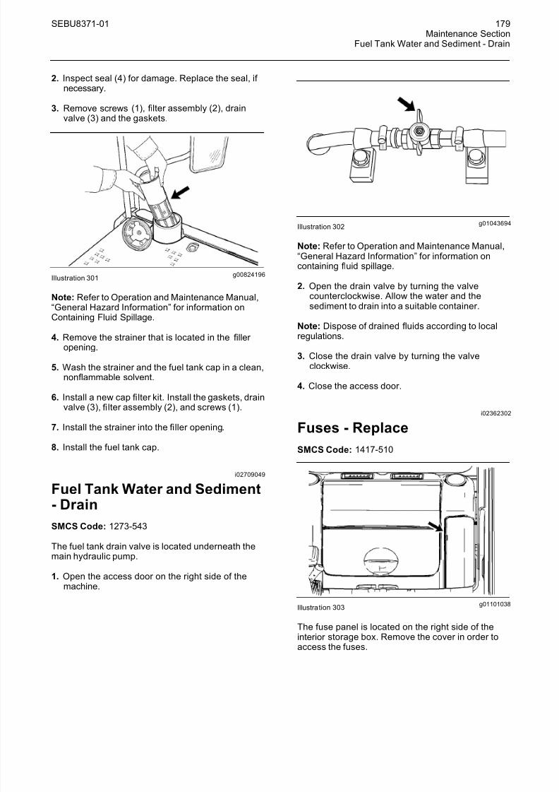
3. Remove screws (1), filter assembly (2), drainvalve (3) and the gaskets.
g00824196Illustration 301
Note: Refer to Operation and Maintenance Manual,“General Hazard Information” for information onContaining Fluid Spillage.
4. Remove the strainer that is located in the filler opening.
5. Wash the strainer and the fuel tank cap in a clean,nonflammable solvent.
6. Install a new cap filter kit. Install the gaskets, drainvalve (3), fi lter assembly (2), and screws (1).
7. Install the strainer into the filler opening.
8. Install the fuel tank cap.
i02709049
Fuel Tank Water and Sediment- Drain
SMCS Code: 1273-543
The fuel tank drain valve is located underneath the
main hydraulic pump.
1. Open the access door on the right side of themachine.
g01043694Illustration 302
Note: Refer to Operation and Maintenance Manual,“General Hazard Information” for information oncontaining fluid spillage.
2. Open the drain valve by turning the valvecounterclockwise. Allow the water and thesediment to drain into a suitable container.
Note: Dispose of drained fluids according to localregulations.
3. Close the drain valve by turning the valveclockwise.
4. Close the access door.
i02362302
Fuses - Replace
SMCS Code: 1417-510
g01101038Illustration 303
The fuse panel is located on the right side of theinterior storage box. Remove the cover in order toaccess the fuses.

8/16/2019 manual mantenimiento excavadora 320d
http://slidepdf.com/reader/full/manual-mantenimiento-excavadora-320d 36/62
180 SEBU8371-01Maintenance SectionFuses - Replace
Fuses – Fuses protect the electricalsystem from damage that is caused byoverloaded circuits. Change a fuse if the
element separates. If the element of a new fuseseparates, check the circuit and/or repair the circuit.
NOTICE Always replace fuses with the same type and capacityfuse that was removed. Otherwise, electrical damagecould result.
NOTICEIf it is necessary to replace fuses frequently, an elec-trical problem may exist.
Contact your Caterpillar dealer.
To replace a fuse, use the puller that is stored in thefuse panel. Two fuses of 5 Amperes, three fuses of 10 Amperes, two fuses of 15 Amperes, and one fuseof 30 Amperes are contained in the fuse panel asspare fuses.
The following list identifies the circuits that areprotected by each fuse. The amperage for each fuseis included with each circuit.
g01179985Illustration 304
(1) Air Conditioner – 15 Amp
(2) Automatic Engine Speed Control (AEC) – 5 Amp
(3) Chassis Light – 10 Amp
(4) Cigar Lighter – 10 Amp
(5) 12 Volt 7 Amp Converter – 10 Amp
(6) Switch Panel And Radio – 5 Amp
(7) Attachment Solenoid – 10 Amp
(8) Seat Heater – 5 Amp
(9) Lower Window Wiper and Window Washer –10 Amp
(10) Window Wiper and Window Washer – 10 Amp
(11) Air Suspension Seat – 10 Amp
(12) 12 Volt 7 Amp Converter – 10 Amp
8/16/2019 manual mantenimiento excavadora 320d
http://slidepdf.com/reader/full/manual-mantenimiento-excavadora-320d 37/62
SEBU8371-01 181Maintenance Section
High Intensity Discharge Lamp (HID) - Replace
(13) Beacon – 10 Amp
(14) Inspection Lamp 2 – 10 Amp
(15) Boom Float – 5 Amp
(16) Spare – 5 Amp
(17) Spare – 5 Amp
(18) Spare – 10 Amp
(19) Spare – 10 Amp
(20) Spare – 15 Amp
(21) Heater and Air Conditioner Blower Fan – 15 Amp
(22) Product Link – 5 Amp
(23) Boom Light – 10 Amp
(24) Air Conditioner Condenser Blower – 10 Amp
(25) Cab Light – 10 Amp
(26) Cab Dome Light and Radio Memory – 10 Amp
(27) Engine Start Switch – 10 Amp
(28) Horn – 10 Amp
(29) Machine Control Module – 15 Amp
(30) Engine Control Module (ECM) – 15 Amp
(31) Inspection Lamp 2 – 10 Amp
(32) Inspection Lamp 3 – 10 Amp
(33) Electric Refueling Pump – 30 Amp
(34) Spare – 5 Amp
(35) Spare – 10 Amp
(36) Spare – 10 Amp
(37) Spare – 10 Amp
(38) Spare – 10 Amp
(39) Spare – 15 Amp
(40) Spare – 30 Amp
i02245859
High Intensity Discharge Lamp(HID) - Replace(If Equipped)
SMCS Code: 1434-510
HID lamps oper ate at very high voltages. To avoidelectrical shock and personal injury, disconnectpower before servicing HID lamps.
HID bulbs become very hot during operation.Before servicing, remove power from lamp for at
least five minutes to ensure lamp is cool.
NOTICE Although HID bulb materials may change over time,HID bulbs produced at the time of the printing of thismanual contain mercury. When disposing of this com-ponent, or any waste that contains mercury, pleaseuse caution and comply with any applicable laws.
1. Remove the electrical power from the highintensity discharge lamp (HID). The electricalpower must be removed from the HID lamp for
at least five minutes, in order to ensure that thebulb is cool.
2. Disassemble the housing for the HID lamp in order to have access to the bulb.
Note: On some HID lamps, the bulb is an integralpart of the lens assembly. The bulb is not removedseparately from the lens assembly. Replace theentire lens assembly on these HID lamps.
3. Remove the bulb from the HID lamp.
4. Install the replacement bulb in the HID lamp.
If the bulb is an integral part of the lens assembly,install the replacement lens assembly in the HIDlamp.
Note: In order to avoid failure to the bulb that ispremature, avoid touching the bulb’s surface withyour bare hands. Clean any fingerprints from the bulbwith alcohol prior to operation.
5. Reassemble the housing for the HID lamp. Ensurethat any printing on the lens is oriented correctlywith respect to the HID lamp’s mounting positionon the machine.
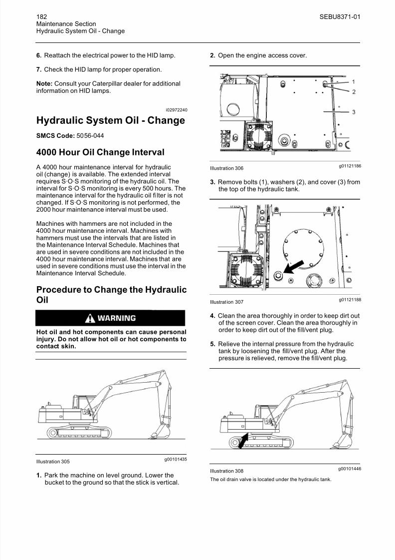
8/16/2019 manual mantenimiento excavadora 320d
http://slidepdf.com/reader/full/manual-mantenimiento-excavadora-320d 38/62
182 SEBU8371-01Maintenance SectionHydraulic System Oil - Change
6. Reattach the electrical power to the HID lamp.
7. Check the HID lamp for proper operation.
Note: Consult your Caterpillar dealer for additionalinformation on HID lamps.
i02972240
Hydraulic System Oil - Change
SMCS Code: 5056-044
4000 Hour Oil Change Interval
A 4000 hour maintenance interval for hydraulicoil (change) is available. The extended intervalrequires S·O·S monitoring of the hydraulic oil. Theinterval for S·O·S monitoring is every 500 hours. The
maintenance interval for the hydraulic oil fi lter is notchanged. If S·O·S monitoring is not performed, the2000 hour maintenance interval must be used.
Machines with hammers are not included in the4000 hour maintenance interval. Machines withhammers must use the intervals that are listed inthe Maintenance Interval Schedule. Machines thatare used in severe conditions are not included in the4000 hour maintenance interval. Machines that areused in severe conditions must use the interval in theMaintenance Interval Schedule.
Procedure to Change the HydraulicOil
Hot oil and hot components can cause personalinjury. Do not allow hot oil or hot components tocontact skin.
g00101435Illustration 305
1. Park the machine on level ground. Lower thebucket to the ground so that the stick is vertical.
2. Open the engine access cover.
g01121186Illustration 306
3. Remove bolts (1), washers (2), and cover (3) fromthe top of the hydraulic tank.
g01121188Illustration 307
4. Clean the area thoroughly in order to keep dirt outof the scr een cover. Clean the area thoroughly inorder to keep dirt out of the fi ll/vent plug.
5. Relieve the internal pressure from the hydraulictank by loosening the fill/vent plug. After thepressure is relieved, remove the fi ll/vent plug.
g00101446Illustration 308
The oil drain valve is located under the hydraulic tank.
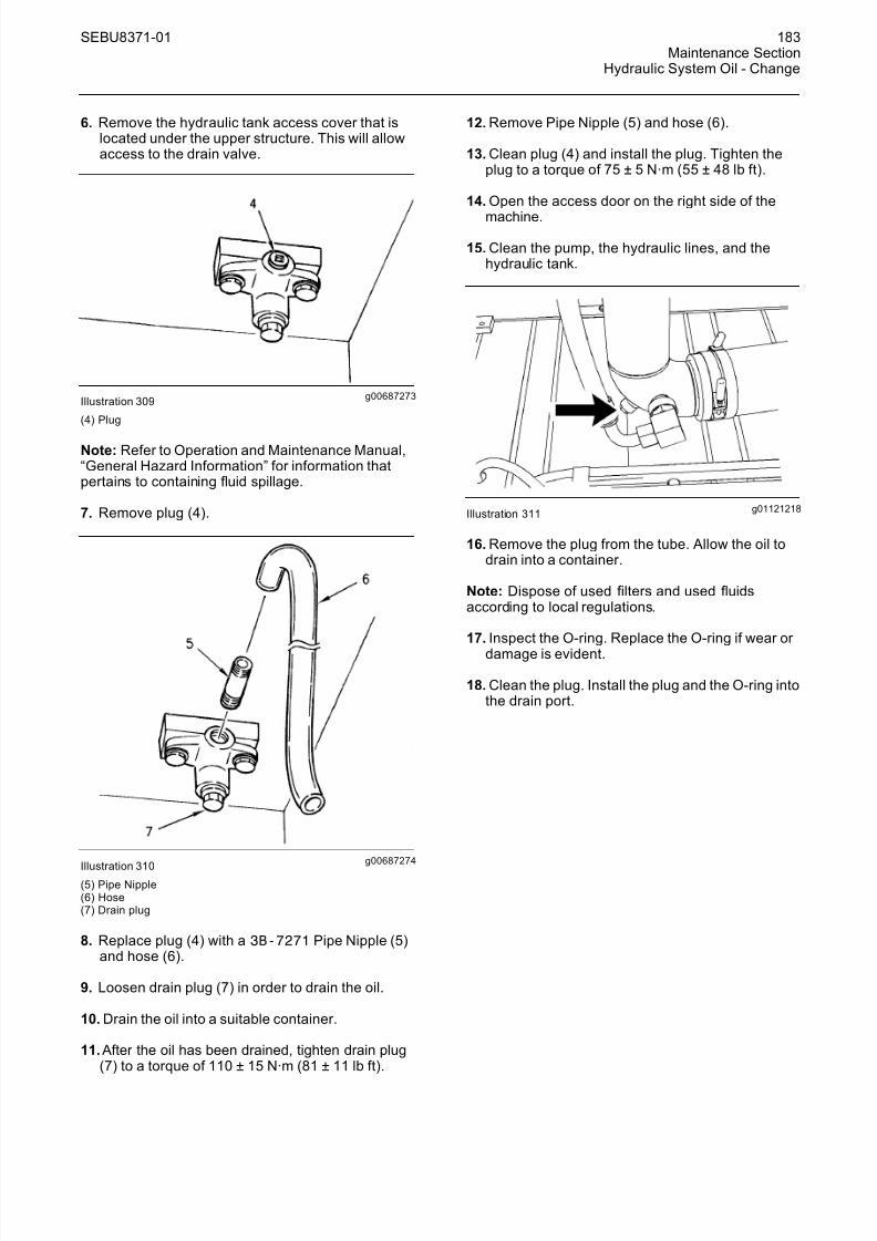
8/16/2019 manual mantenimiento excavadora 320d
http://slidepdf.com/reader/full/manual-mantenimiento-excavadora-320d 39/62
SEBU8371-01 183Maintenance Section
Hydraulic System Oil - Change
6. Remove the hydr aulic tank access cover that islocated under the upper structure. This will allowaccess to the drain valve.
g00687273Illustration 309
(4) Plug
Note: Refer to Operation and Maintenance Manual,“General Hazard Information” for information thatpertains to containing fluid spillage.
7. Remove plug (4).
g00687274
Illustration 310(5) Pipe Nipple(6) Hose(7) Drain plug
8. Replace plug (4) with a 3B-7271 Pipe Nipple (5)and hose (6).
9. Loosen drain plug (7) in order to drain the oil.
10. Drain the oil into a suitable container.
11. After the oil has been drained, tighten drain plug(7) to a torque of 110 ± 15 N·m (81 ± 11 lb ft).
12. Remove Pipe Nipple (5) and hose (6).
13. Clean plug (4) and install the plug. Tighten theplug to a torque of 75 ± 5 N·m (55 ± 48 lb ft).
14. Open the access door on the right side of the
machine.
15. Clean the pump, the hydraulic lines, and thehydraulic tank.
g01121218Illustration 311
16. Remove the plug from the tube. Allow the oil todrain into a container.
Note: Dispose of used filters and used fluidsaccording to local regulations.
17. Inspect the O-ring. Replace the O-ring if wear or
damage is evident.
18. Clean the plug. Install the plug and the O-ring intothe drain port.
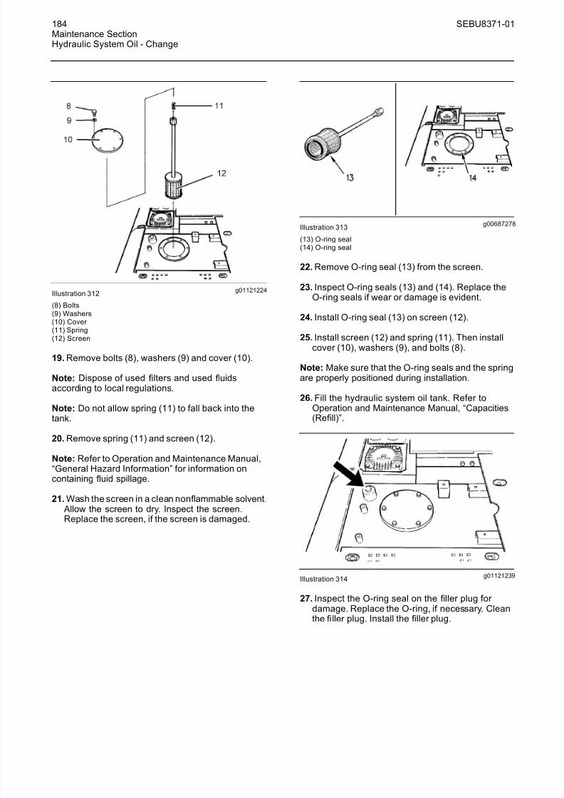
8/16/2019 manual mantenimiento excavadora 320d
http://slidepdf.com/reader/full/manual-mantenimiento-excavadora-320d 40/62
184 SEBU8371-01Maintenance SectionHydraulic System Oil - Change
g01121224Illustration 312
(8) Bolts(9) Washers(10) Cover (11) Spring(12) Screen
19. Remove bolts (8), washers (9) and cover (10).
Note: Dispose of used filters and used fluidsaccording to local regulations.
Note: Do not allow spring (11) to fall back into the
tank.
20. Remove spring (11) and screen (12).
Note: Refer to Operation and Maintenance Manual,“General Hazard Information” for information oncontaining fluid spillage.
21. Wash the screen in a clean nonflammable solvent. Allow the screen to dry. Inspect the screen.Replace the screen, if the screen is damaged.
g00687278Illustration 313
(13) O-ring seal(14) O-ring seal
22. Remove O-ring seal (13) from the screen.
23. Inspect O-ring seals (13) and (14). Replace theO-ring seals if wear or damage is evident.
24. Install O-ring seal (13) on screen (12).
25. Install screen (12) and spring (11). Then installcover (10), washers (9), and bolts (8).
Note: Make sure that the O-ring seals and the springare properly positioned during installation.
26. Fill the hydraulic system oil tank. Refer toOperation and Maintenance Manual, “Capacities
(Refill)”.
g01121239Illustration 314
27. Inspect the O-ring seal on the filler plug for damage. Replace the O-ring, if necessary. Cleanthe fi ller plug. Install the filler plug.

8/16/2019 manual mantenimiento excavadora 320d
http://slidepdf.com/reader/full/manual-mantenimiento-excavadora-320d 41/62
SEBU8371-01 185Maintenance Section
Hydraulic System Oil - Change
g01121430Illustration 315
(15) Drain hose(16) Connector (17) Seal(18) Negative flow control hose
Note: Make no attempt to start the engine until thepump has been filled with hydraulic oil. Seriousdamage to the hydraulic components can result.
28. When the hydraulic oil has been replaced, the air must be removed from the hydraulic oil system.To remove the air from the hydraulic oil system,follow Step 28.a through Step 28.g.
a. While the engine is stopped, remove drainhose (15), connector (16) and seal (17) fromthe top of the pump. Add hydraulic oil throughthe opening.
b. Check the condition of seal (17). If the seal isdamaged, replace the seal.
c. After the pump has been fi lled with oil, installdrain hose (15), connector (16) and seal (17) tothe original locations.
d. Start the engine. When the engine is at lowidle, fully raise the boom. Hold the boom in thisposition.
e. Slowly loosen negative flow control hose (18)until the air has been released from the pump.
f. Tighten negative flow control hose (18).
g. Stop the engine. Slowly lower the boom untilthe bucket is on the ground. This pressurizesthe hydraulic tank.
g01121273Illustration 316
(19) Fitting
h. Slowly loosen fitting (19) until the hydraulic oilflows out of the opening. This indicates that the
air has been released from the pump.
i. Tighten fitting (19).
29. Start the engine. Operate the engine at idlingspeed for five minutes.
g00101435Illustration 317
30. Operate the joysticks in order to circulate thehydraulic oil. Lower the bucket to the ground sothat the stick is vertical to the ground. Stop theengine.
31. Check the hydraulic oil level.
Reference: For the correct procedure, refer toOperation and Maintenance Manual, “HydraulicSystem Oil Level - Check”.
32. Close the access door.
33. Close the engine hood and latch the engine hood.
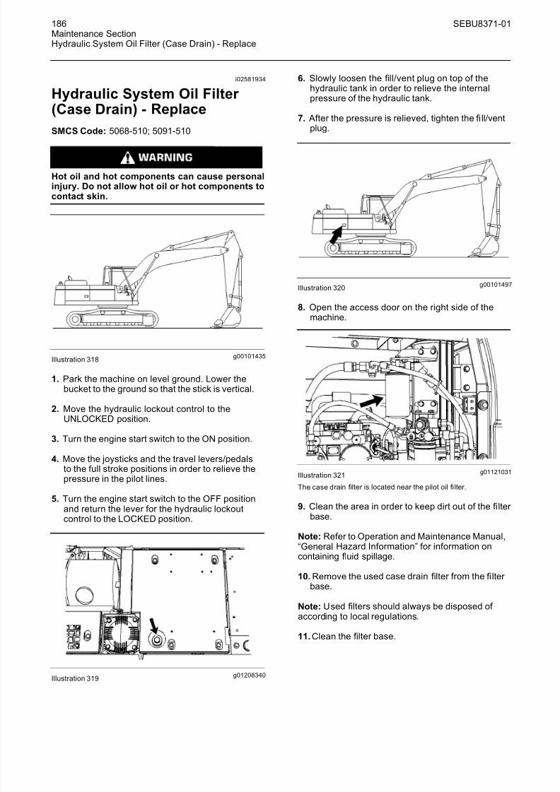
8/16/2019 manual mantenimiento excavadora 320d
http://slidepdf.com/reader/full/manual-mantenimiento-excavadora-320d 42/62
186 SEBU8371-01Maintenance SectionHydraulic System Oil Filter (Case Drain) - Replace
i02581934
Hydraulic System Oil Filter (Case Drain) - Replace
SMCS Code: 5068-510; 5091-510
Hot oil and hot components can cause personalinjury. Do not allow hot oil or hot components tocontact skin.
g00101435Illustration 318
1. Park the machine on level ground. Lower thebucket to the ground so that the stick is vertical.
2. Move the hydraulic lockout control to the
UNLOCKED position.
3. Turn the engine start switch to the ON position.
4. Move the joysticks and the travel levers/pedalsto the full stroke positions in order to relieve thepressure in the pilot lines.
5. Turn the engine start switch to the OFF positionand return the lever for the hydraulic lockoutcontrol to the LOCKED position.
g01208340Illustration 319
6. Slowly loosen the fill/vent plug on top of thehydraulic tank in order to relieve the internalpressure of the hydraulic tank.
7. After the pressure is relieved, tighten the fi ll/ventplug.
g00101497Illustration 320
8. Open the access door on the right side of themachine.
g01121031Illustration 321
The case drain filter is located near the pilot oil fi lter.
9. Clean the area in order to keep dirt out of the filter base.
Note: Refer to Operation and Maintenance Manual,“General Hazard Information” for information on
containing fluid spillage.
10. Remove the used case drain filter from the fi lter base.
Note: Used filters should always be disposed of according to local regulations.
11. Clean the filter base.

8/16/2019 manual mantenimiento excavadora 320d
http://slidepdf.com/reader/full/manual-mantenimiento-excavadora-320d 43/62
SEBU8371-01 187Maintenance Section
Hydraulic System Oil Filter (Pilot) - Replace
g00101502Illustration 322
12. Coat the seal of a new case drain fi lter with cleanhydraulic oil.
13. Install the new oil fi lter by hand.
Instructions for the installation of the filter areprinted on the side of each Caterpillar spin-onfilter. For non-Caterpillar filters, refer to theinstallation instructions that are provided by thesupplier of the fi lter.
14. Start the engine and operate the machine slowlyfor 10 to 15 minutes. Move each cylinder evenlythrough several cycles.
g00101508Illustration 323
15. Return the machine to the position that is shownin Illustration 323. Check the machine for oil leaks.
16. Stop the engine.
17. Check the hydraulic oil level.
Reference: For the correct procedure, refer toOperation and Maintenance Manual, “HydraulicSystem Oil Level - Check”.
18. Close the access door.
i02581929
Hydraulic System Oil Filter (Pilot) - Replace
SMCS Code: 5068-510; 5068-510-PS; 5092-510
Hot oil and hot components can cause personalinjury. Do not allow hot oil or hot components tocontact skin.
g00101435Illustration 324
1. Park the machine on level ground. Lower thebucket to the ground so that the stick is vertical.
2. Move the hydraulic lockout control to the
UNLOCKED position.
3. Turn the engine start switch to the ON position.
4. Move the joysticks and the travel levers/pedalsto the full stroke positions in order to relieve thepressure in the pilot lines.
5. Turn the engine start switch to the OFF positionand return the lever for the hydraulic lockoutcontrol to the LOCKED position.
g01208340Illustration 325

8/16/2019 manual mantenimiento excavadora 320d
http://slidepdf.com/reader/full/manual-mantenimiento-excavadora-320d 44/62
188 SEBU8371-01Maintenance SectionHydraulic System Oil Filter (Return) - Replace
6. Slowly loosen the fill/vent plug on top of thehydraulic tank in order to relieve the internalpressure of the hydraulic tank.
7. After the pressure is relieved, tighten the fill/ventplug.
g00101497Illustration 326
8. Open the access door on the right side of themachine.
g01121062Illustration 327
9. Clean the area in order to keep dirt out of the filter base.
Note: Ref er to Operation and Maintenance Manual,“General Hazard Information” for information oncontaining fluid spillage.
10. Remove the used pilot filter element from thefilter base.
Note: Used filters should always be disposed of according to local regulations.
11. Clean the filter base.
g00101502Illustration 328
12. Coat the seal of a new pilot filter with cleanhydraulic oil.
13. Install the new oil filter by hand.
Instructions for the installation of the filter areprinted on the side of each Caterpillar spin-onfilter. For non-Caterpillar filters, refer to theinstallation instructions that are provided by thesupplier of the filter.
14. Check the hydraulic oil level.
Reference: For the correct procedure, refer toOperation and Maintenance Manual, “HydraulicSystem Oil Level - Check”.
15. Close the access door.
i02580552
Hydraulic System Oil Filter (Return) - Replace
SMCS Code: 5068-510-RJ
Hot oil and hot components can cause personalinjury. Do not allow hot oil or hot components tocontact skin.
The return fi lter is a cartridge type fi lter. The amountof foreign material that enters the hydraulic system isreduced when the fi lter element is replaced.
Two different fi lters are available for the return fi lter.One fi lter is used for standard applications such asdigging and normal use of a hammer. The secondfilter is used for an application such as demolishing aceiling in a tunnel with a hammer.

8/16/2019 manual mantenimiento excavadora 320d
http://slidepdf.com/reader/full/manual-mantenimiento-excavadora-320d 45/62
SEBU8371-01 189Maintenance Section
Hydraulic System Oil Filter (Return) - Replace
Note: If the message display shows that the hydraulicreturn filter is plugged, turn off the machine. After youmake sure that the warning has disappeared, startthe machine and run the machine on level ground for approximately 10 minutes. If the warning still appearsin the message display, inspect the filter and replace
the filter, if necessary.
g01220269Illustration 329
1. Loosen the fill/vent plug in order to relieve thehydraulic tank pressure. Tighten the fi ll/vent plugafter the hydraulic tank pressure is relieved.
Note: The return filter cartridge is located on the sideof the hydraulic tank.
2. Remove the filter cartridge. Perform Step 2.athrough Step 2.f in order to remove the filter cartridge.
g00102211Illustration 330
(1) Bolts(2) Washers(3) Cover (4) Plug(5) Filter cartridge
a. Remove bolts (1), washers (2), and cover (3).
Note: Refer to Operation and Maintenance Manual,“General Hazard Information” for information oncontaining fluid spillage.
b. Remove plug (4) in order to release thepressure in filter cartridge (5).
Note: When plug (4) is removed the oil level in thereturn fi lter drops to the level of the hydraulic tank.
g00102212Illustration 331
(5) Filter cartridge(6) Filter case(A) Guide
c. Pull up the handle at the top of filter cartridge(5) until the filter cartridge contacts guide (A)on filter case (6).
g00102214Illustration 332
d. Turn the filter cartridge counterclockwise by180 degrees in order to align the projection of the filter cartridge with the notch of the filter
case. Pull out the fi lter cartridge.

8/16/2019 manual mantenimiento excavadora 320d
http://slidepdf.com/reader/full/manual-mantenimiento-excavadora-320d 46/62
190 SEBU8371-01Maintenance SectionHydraulic System Oil Filter (Return) - Replace
g00102219Illustration 333
(7) O-ring
e. Inspect the cover and O-ring (7). If either partis damaged, replace the part.
f. Inspect the filter cartridge for debris andfor damage. If necessary, replace the filter cartridge.
3. Remove the filter element. Perform Step 3.athrough Step 3.f in order to remove the filter element.
g00104507Illustration 334
(4) Plug(8) Plate(18) O-ring
a. Make sure that plug (4) is removed. Make surethat all of O-ring (18) is removed from plate (8).
g00918893Illustration 335
(8) Plate(9) Spiral retaining ring
b. Remove spiral retaining ring (9).
g00104510Illustration 336
(8) Plate(10) Shell(11) O-ring(12) Filter element
c. Hold the filter cartridge with one hand. Graspthe grip of plate (8) with your other hand. Liftplate (8) in order to separate plate (8) from thefilter cartr idge.
d. Remove O-ring (11) from plate (8).
e. Lift fi
lter element (12) from shell (10).
f. Pour the remaining oil into a suitable container.
Note: Dispose of used oil according to localregulations.
g. Repeat Step 3.a through Step 3.f for the other filter groups.
4. Clean the shell of the fi lter cartridge. Perform Step4.a through Step 4.d in order to clean the shell of the filter cartridge.

8/16/2019 manual mantenimiento excavadora 320d
http://slidepdf.com/reader/full/manual-mantenimiento-excavadora-320d 47/62
SEBU8371-01 191Maintenance Section
Hydraulic System Oil Filter (Return) - Replace
g00104511Illustration 337
(13) Slide plate(14) Pads(15) Screws(19) Port
a. Turn shell (10) upside-down.
b. Remove screws (15).
c. Remove Pads (14) from slide plate (13).
d. Wash the following parts in a cleannonflammable solvent: plug (4), plate (8), spiralretaining ring (9), shell (10), and Pads (14). Drythe parts.
5. Install the filter elements. Perform Step 5.a throughStep 5.k in order to install the filter elements.
Note: Consult a Caterpillar dealer for the Service Kitthat is needed to install the filter element and thefilter cartridge.
a. Apply spray type oil to the inside of shell (10) inorder to prevent rust.
b. Apply grease to a new O-ring (11).
c. Plate (8) will contact the inside of shell (10). Apply grease to this point.
d. Apply grease to O-rings inside ports (19) at the
bottom of shell (10).
e. Install new Pads (14). Tighten the screws to atorque of 0.4 N·m (3.5 lb in).
f. Apply spray type oil into the clearance betweenshell (10) and slide plate (13).
g00104512Illustration 338
(8) Plate(10) Shell(16) Boss(17) Notch
g. Turn over shell (10). Apply grease to the twoO-rings on new element (12). Install element(12) into shell (10).
h. Move boss (16) in alignment with notch (17).Install plate (8) into shell (10).
i. Install spiral retaining ring (9) into the groovein shell (10).
j. Apply grease to new O-ring (18). Install O-ring(18) on plug (4).
k. Install plug (4) into plate (8).
6. Install the filter cartridge. Perform Step 6.a throughStep 6.e in order to install the filter cartridge.
g00102220Illustration 339
(B) Port(C) Slide plate
a. Check that ports (B) at the bottom of the filter case are closed.

8/16/2019 manual mantenimiento excavadora 320d
http://slidepdf.com/reader/full/manual-mantenimiento-excavadora-320d 48/62
192 SEBU8371-01Maintenance SectionHydraulic System Oil Level - Check
Note: If the por ts are open, rotate slide plate (C)counterclockwise to the stopper in order to fullyclose the ports. When the ports are fully closed, anyremaining oil in the filter case should be completelyremoved.
g00102221
Illustration 340(E) Slide plate(D) Port
b. Check that ports (D) of the filter cartridge arefully closed.
Note: The filter cartridge cannot be installed unlessthe ports are fully closed. If the ports are open, rotateslide plate (E) counterclockwise to the stopper inorder to fully close the ports.
g00102222Illustration 341
(F) O-rings
c. Check that O-rings (F) have been installed andthat oil has been applied to O-rings (F).
g00102225Illustration 342
(1) Bolts
d. Install the filter cartridge into the filter case.Turn the filter cartridge clockwise by 180
degrees and push down the filter cartridgewhen the filter cartridge contacts guide (A).
e. Install plug (4), cover (3), washers (2), and bolts(1). Tighten bolts (1) to a torque of 29 ± 5 N·m(22 ± 4 lb ft).
7. Check the hydraulic system oil level.
Reference: For the correct procedure, refer toOperation and Maintenance Manual, “HydraulicSystem Oil Level - Check”.
i02581923
Hydraulic System Oil Level -Check
SMCS Code: 5050-535
Hot oil and hot components can cause personalinjury. Do not allow hot oil or hot components tocontact skin.
NOTICENever remove the fill/vent plug from the hydraulic tankif the oil is hot.
Air can enter the system and cause pump damage.

8/16/2019 manual mantenimiento excavadora 320d
http://slidepdf.com/reader/full/manual-mantenimiento-excavadora-320d 49/62
SEBU8371-01 193Maintenance Section
Hydraulic System Oil Level - Check
g00102817Illustration 343
The hydraulic oil tank is on the right side of the machine.
1. Park the machine on level ground. Lower thebucket to the ground with the stick in a vertical
position, as shown.
g00102818Illustration 344
2. Open the access door on the right side of themachine.
g01121278Illustration 345
(A) High temperature range(B) Low temperature range
3. For a cold machine, maintain the hydraulic oil levelin the low temperature range (B). For a machinethat is at normal operating temperature, maintainthe hydraulic oil level in the high temperaturerange (A).
4. Close the access door.
g01208340Illustration 346
Note: Refer to Operation and Maintenance Manual,“General Hazard Information” for information thatpertains to Containing Fluid Spillage.
Note: Perform Step 5 through Step 7 if the oil levelis low.
5. Slowly loosen the fill/vent plug in order to relieveany pressure. Add oil, if necessary. See Operationand Maintenance, “Lubricant Viscosities”.
6. Check the O-ring seal of the fill/vent plug. Replacethe O-ring seal if the O-ring seal is damaged.
7. Clean the fill/vent plug and install the fi ll/vent plug.

8/16/2019 manual mantenimiento excavadora 320d
http://slidepdf.com/reader/full/manual-mantenimiento-excavadora-320d 50/62
194 SEBU8371-01Maintenance SectionHydraulic System Oil Sample - Obtain
i01874371
Hydraulic System Oil Sample- Obtain
SMCS Code: 5050-008-OC; 5095-008; 5095-SM;
7542-008; 7542
g00684914Illustration 347
The hydraulic oil sampling valve is near the pilot filter.Obtain a sample of the hydraulic oil from the hydraulicoil sampling valve that is located on the hydraulicoil filter housing. Refer to Special Publication,SEBU6250, “S·O·S Oil Analysis” for information thatpertains to obtaining a sample of the hydraulic oil.Refer to Special Publication, PEHP6001, “How ToTake A Good Oil Sample” for more information aboutobtaining a sample of the hydraulic oil.
i02581915
Hydraulic Tank Screen - Clean
SMCS Code: 5056-070-Z3
Hot oil and hot components can cause personalinjury. Do not allow hot oil or hot components tocontact skin.
g00101435Illustration 348
1. Park the machine on level ground. Lower thebucket to the ground so that the stick is vertical.
2. Unlatch the engine hood and raise the enginehood.
g01121186Illustration 349
(1) Bolts(2) Washers(3) Cover
3. Remove bolts (1), washers (2) and cover (3) fromthe top of the hydraulic tank.
g01121188Illustration 350
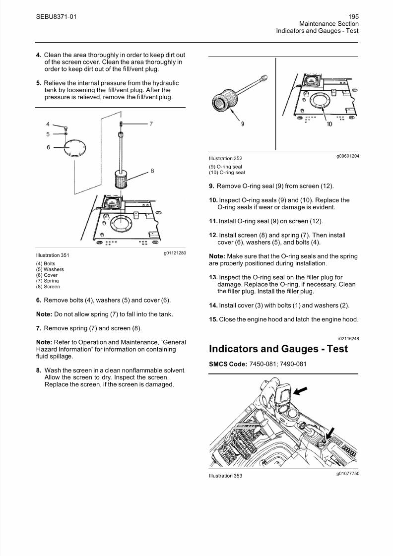
8/16/2019 manual mantenimiento excavadora 320d
http://slidepdf.com/reader/full/manual-mantenimiento-excavadora-320d 51/62
SEBU8371-01 195Maintenance Section
Indicators and Gauges - Test
4. Clean the area thoroughly in order to keep dirt outof the screen cover. Clean the area thoroughly inorder to keep dirt out of the fi ll/vent plug.
5. Relieve the internal pressure from the hydraulictank by loosening the fill/vent plug. After the
pressure is r elieved, remove the fi ll/vent plug.
g01121280Illustration 351
(4) Bolts(5) Washers(6) Cover (7) Spring(8) Screen
6. Remove bolts (4), washers (5) and cover (6).
Note: Do not allow spring (7) to fall into the tank.
7. Remove spring (7) and screen (8).
Note: Refer to Operation and Maintenance, “GeneralHazard Information” for information on containingfluid spillage.
8. Wash the screen in a clean nonflammable solvent. Allow the screen to dry. Inspect the screen.Replace the screen, if the screen is damaged.
g00691204Illustration 352
(9) O-ring seal(10) O-ring seal
9. Remove O-ring seal (9) from screen (12).
10. Inspect O-ring seals (9) and (10). Replace theO-ring seals if wear or damage is evident.
11. Install O-ring seal (9) on screen (12).
12. Install screen (8) and spring (7). Then installcover (6), washers (5), and bolts (4).
Note: Make sure that the O-ring seals and the springare properly positioned during installation.
13. Inspect the O-ring seal on the filler plug for damage. Replace the O-ring, if necessary. Clean
the fi ller plug. Install the filler plug.
14. Install cover (3) with bolts (1) and washers (2).
15. Close the engine hood and latch the engine hood.
i02116248
Indicators and Gauges - Test
SMCS Code: 7450-081; 7490-081
g01077750Illustration 353

8/16/2019 manual mantenimiento excavadora 320d
http://slidepdf.com/reader/full/manual-mantenimiento-excavadora-320d 52/62
196 SEBU8371-01Maintenance SectionOil Filter - Inspect
1. Look for broken lenses on the gauges, brokenindicator lights, broken switches, and other brokencomponents in the cab.
2. Start the engine.
3. Look for inoperative gauges.
4. Turn on all machine lights. Check for proper operation.
5. Move the machine forward. Release the travellevers and the travel pedals. The machine shouldstop.
6. Stop the engine.
7. Make any repairs that are required beforeoperating the machine.
i02106227
Oil Filter - Inspect
SMCS Code: 1308-507; 5068-507
Inspect a Used Filter for Debris
g00100013Illustration 354
The element is shown with debris.
Use a filter cutter to cut the filter element open.Spread apart the pleats and inspect the element for
metal and for other debris. An excessive amount of debris in the filter element can indicate a possiblefailure.
If metals are found in the fi lter element, a magnet canbe used to differentiate between ferrous metals andnonferrous metals.
Ferrous metals can indicate wear on steel parts andon cast iron parts.
Nonferrous metals can indicate wear on thealuminum parts of the engine such as main bearings,rod bearings, or turbocharger bearings.
Small amounts of debris may be found in the filter element. This could be caused by friction and by
normal wear. Consult your Caterpillar dealer in order to arrange for further analysis if an excessive amountof debris is found.
Using an oil filter element that is not recommendedby Caterpillar can result in severe engine damageto engine bearings, to the crankshaft, and to other parts. This can result in larger particles in unfilteredoil. The particles could enter the lubricating systemand the particles could cause damage.
i02461929
Quick Coupler - Lubricate(If Equipped)
SMCS Code: 6129-086
Note: Caterpillar recommends the use of 5% molybdenum grease. Refer to SpecialPublication, SEBU6250, “Caterpillar MachineFluids Recommendations” for more information onmolybdenum grease.
Wipe all fittings before you apply lubricant.
g00104878Illustr ation 355
Typical Example
Apply lubricant through the four fittings on the quickcoupler. The quick coupler has two fittings on eachside.
Note: Do not lubricate the wedge and the wear plates. Friction is needed in order to hold the wedgein place during backfilling.

8/16/2019 manual mantenimiento excavadora 320d
http://slidepdf.com/reader/full/manual-mantenimiento-excavadora-320d 53/62
SEBU8371-01 197Maintenance Section
Radiator Core - Clean
i02332977
Radiator Core - Clean
SMCS Code: 1353-070
1. Open the rear access door on the left side of themachine.
g01164503Illustration 356
2. Lift latch (1) in order to release the latch.
3. Swing the hydraulic oil cooler outward.
g01164506Illustration 357
4. Remove four pins (3).
5. Remove screens (2) and (4).
6. Check all of the core fins for debris.
7. Remove dust and debris from all of the core finsand from the screens.
Compressed air is preferred, but high pressurewater or steam can be used to remove dust andgeneral debris from a core.
See Special Publication, SEBD0518, “Know Your Cooling System” for more detailed information
about cleaning core fins.
8. Install screens (2) and (4) with pins (3).
9. Close and latch the hydraulic oil cooler.
10. Close the rear access door on the left side of themachine.
i02723802
Receiver Dryer (Refrigerant) -Replace
SMCS Code: 7322-510; 7322-710
Personal injury can result from contact with refrig-erant.
Contact with refrigerant can cause frost bite. Keepface and hands away to help prevent injury.
Protective goggles must always be worn when re-frigerant lines are opened, even if the gauges in-
dicate the system is empty of refrigerant.
Always use precaution when a fitting is removed.Slowly loosen the fitting. If the system is still un-der pressure, release it slowly in a well ventilatedarea.
Personal injury or death can result from inhalingrefrigerant through a lit cigarette.
Inhaling air conditioner refrigerant gas through alit cigarette or other smoking method or inhalingfumes released from a flame contacting air con-ditioner refrigerant gas, can cause bodily harm or
death.
Do not smoke when servicing air conditioners or wherever refrigerant gas may be present.
Use a certified recovery and recycling cart to prop-erly remove the refrigerant from the air condition-ing system.
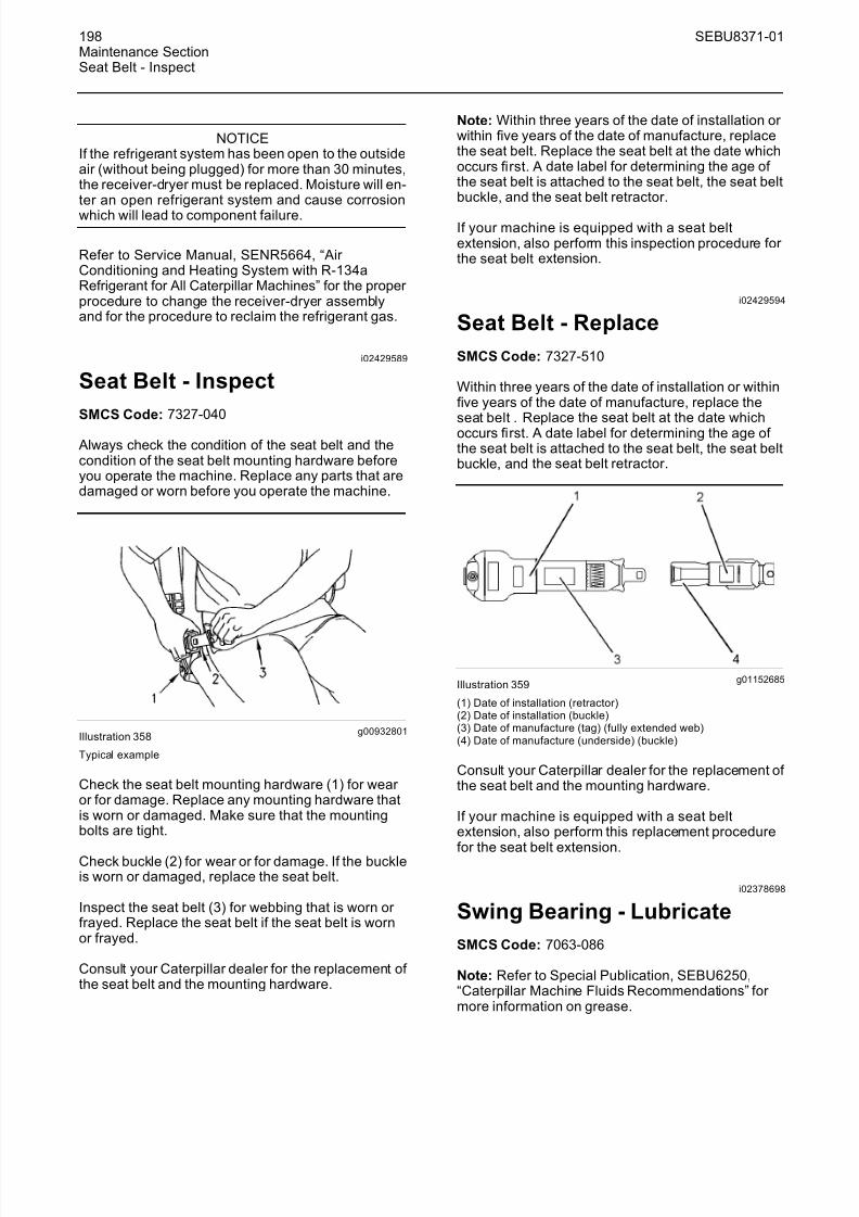
8/16/2019 manual mantenimiento excavadora 320d
http://slidepdf.com/reader/full/manual-mantenimiento-excavadora-320d 54/62
198 SEBU8371-01Maintenance SectionSeat Belt - Inspect
NOTICEIf the refriger ant system has been open to the outsideair (without being plugged) for more than 30 minutes,the receiver-dryer must be replaced. Moisture will en-ter an open ref rigerant system and cause corrosion
which will lead to component failure.
Refer to Service Manual, SENR5664, “Air Conditioning and Heating System with R-134aRefrigerant for All Caterpillar Machines” for the proper procedure to change the receiver-dryer assemblyand for the procedure to reclaim the refrigerant gas.
i02429589
Seat Belt - Inspect
SMCS Code: 7327-040
Always check the condition of the seat belt and thecondition of the seat belt mounting hardware beforeyou operate the machine. Replace any parts that aredamaged or worn before you operate the machine.
g00932801Illustration 358
Typical example
Check the seat belt mounting hardware (1) for wear or for damage. Replace any mounting hardware thatis worn or damaged. Make sure that the mountingbolts are tight.
Check buckle (2) for wear or for damage. If the buckleis worn or damaged, replace the seat belt.
Inspect the seat belt (3) for webbing that is worn or frayed. Replace the seat belt if the seat belt is wornor frayed.
Consult your Caterpillar dealer for the replacement of the seat belt and the mounting hardware.
Note: Within three years of the date of installation or within five years of the date of manufacture, replacethe seat belt. Replace the seat belt at the date whichoccurs first. A date label for determining the age of the seat belt is attached to the seat belt, the seat beltbuckle, and the seat belt retractor.
If your machine is equipped with a seat beltextension, also perform this inspection procedure for the seat belt extension.
i02429594
Seat Belt - Replace
SMCS Code: 7327-510
Within three years of the date of installation or withinfive years of the date of manufacture, replace theseat belt . Replace the seat belt at the date whichoccurs first. A date label for determining the age of the seat belt is attached to the seat belt, the seat beltbuckle, and the seat belt retractor.
g01152685Illustration 359
(1) Date of installation (retractor)(2) Date of installation (buckle)(3) Date of manufacture (tag) (fully extended web)(4) Date of manufacture (underside) (buckle)
Consult your Caterpillar dealer for the replacement of the seat belt and the mounting hardware.
If your machine is equipped with a seat beltextension, also perform this replacement procedure
for the seat belt extension.
i02378698
Swing Bearing - Lubricate
SMCS Code: 7063-086
Note: Refer to Special Publication, SEBU6250,“Caterpillar Machine Fluids Recommendations” for more information on grease.

8/16/2019 manual mantenimiento excavadora 320d
http://slidepdf.com/reader/full/manual-mantenimiento-excavadora-320d 55/62
SEBU8371-01 199Maintenance Section
Swing Drive Oil - Change
Note: Do not overgrease the swing bearings. Do notgrease more than the recommended maintenanceinterval. Refer to Operation and MaintenanceManual, “Maintenance Interval Schedule” for moreinformation.
Wipe the fittings before you lubricate the swingbearing.
g00101569Illustration 360
The swing bearing is located under the base of theboom.
g00687903Illustration 361
Apply lubricant through the fittings until the lubricantover flows the bearing seals.
i02582097
Swing Drive Oil - Change
SMCS Code: 5459-044
Hot oil and hot components can cause personalinjury. Do not allow hot oil or hot components tocontact skin.
g00101586Illustration 362
The oil drain hose is under the center of the upper structure.
g00687981
Illustration 363
Note: Refer to Operation and Maintenance Manual,“General Hazard Information” for information thatpertains to Containing Fluid Spillage.
1. Remove dr ain hose (2) from holder (1) on theupper frame. Face the end of the hose towardthe container.
2. Use a universal joint with a socket extension toloosen the drain valve in hole (3). Drain the oil intoa suitable container.
Note: Drained fluids should always be disposed of according to local regulations.

8/16/2019 manual mantenimiento excavadora 320d
http://slidepdf.com/reader/full/manual-mantenimiento-excavadora-320d 56/62
200 SEBU8371-01Maintenance SectionSwing Drive Oil Level - Check
g00687982Illustration 364
3. Tighten the drain valve. Hook the drain hose (2)to the holder (1). Make sure that the end of thehose is facing upward.
g00687983Illustration 365
4. Remove dipstick (4).
5. Add the specified quantity of oil through thedipstick tube. See Operation and Maintenance,“Capacities (Refill)”.
6. Check the oil level. Refer to Operation andMaintenance Manual, “Swing Drive Oil Level -Check” for the procedure.
7. Check the oil that has been drained for metal chips
or metal particles. Consult your Caterpillar dealer if any metal chips or metal particles are found.
8. Drained materials should always be disposed of according to local regulations.
i02582101
Swing Drive Oil Level - Check
SMCS Code: 5459-535-FLV
Hot oil and hot components can cause personalinjury. Do not allow hot oil or hot components tocontact skin.
g00101622Illustration 366
The dipstick for the swing drive oil is on the swingdrive at the rear base of the boom.
g00684917Illustration 367
1. Remove the dipstick.

8/16/2019 manual mantenimiento excavadora 320d
http://slidepdf.com/reader/full/manual-mantenimiento-excavadora-320d 57/62
SEBU8371-01 201Maintenance Section
Swing Drive Oil Sample - Obtain
g01049757Illustration 368
Note: Refer to Operation and Maintenance Manual,“General Hazard Information” for information thatpertains to Containing Fluid Spillage.
2. Check the dipstick. Maintain the oil level betweenthe marks on the dipstick. Add oil through thedipstick tube, if necessary. Refer to Operationand Maintenance Manual, “Lubricant Viscosities”when you select an oil. If the oil level is abovethe “FULL” line, then remove oil from the system.Restore the oil to the correct level position.
3. Insert the dipstick.
i02582981
Swing Drive Oil Sample -Obtain
SMCS Code: 5459-008; 5459-008-OC;5459-554-OC; 5459-OC; 7542-008
Hot oil and hot components can cause personalinjury. Do not allow hot oil or hot components tocontact skin.
g00684917Illustration 369
Obtain an oil sample of the swing drive oil through theopening for the dipstick. Refer to Special Publication,SEBU6250, “S·O·S Oil Analysis” for informationthat pertains to obtaining an oil sample from theswing drive housing. Refer to Special Publication,PEHP6001, “How To Take A Good Oil Sample” for
more information about obtaining an oil sample fromthe swing drive housing.
i01963879
Swing Gear - Lubricate
SMCS Code: 7063-086
Note: Refer to Special Publication, SEBU6250,“Caterpillar Machine Fluids Recommendations” for more information on grease.
NOTICEImproper lubrication can cause damage to machinecomponents.
To avoid damage, make sure that the proper amountof grease is applied to the swing drive.
When the amount of grease in the compartment be-comes too large, the agitation loss becomes large,thereby accelerating grease deterioration.
Grease deterioration can cause damage to the piniongear of the swing drive and swing internal gear.
Not enough grease will result in poor gear lubrication.
g00688052Illustration 370
Remove the inspection cover that is located near theboom base. Inspect the grease.

8/16/2019 manual mantenimiento excavadora 320d
http://slidepdf.com/reader/full/manual-mantenimiento-excavadora-320d 58/62
202 SEBU8371-01Maintenance SectionSwing Gear - Lubricate
g00688056Illustration 371
(1) Bolts(2) Washers(3) Cover (4) Gasket
1. Remove bolts (1) and washers (2). Remove cover (3) and gasket (4).
g00688058Illustration 372
(3) Cover (4) Gasket
2. Inspect gasket (4). Replace the gasket if damageis evident.
3. Check the level of the grease. The grease shouldbe evenly distributed on the floor of the pan.
Refer to Operation and Maintenance Manual,“Capacities (Refill)” for the size of the pan.
Add grease, as needed. Remove grease, asneeded. Too much grease will result in thedeterioration of the grease because of excessivemovement of the grease. Too little grease willresult in poor lubrication of the swing gear.
g00688063Illustration 373
(5) Bolts(6) Washers(7) Cover (8) Gasket
4. Check for contamination and for discoloredgrease.
5. If the grease is contaminated or discolored withwater, change the grease. Remove bolts (5),washers (6), cover (7), and gasket (8) in order to allow the water to drain. When you reinstallcover (7), inspect gasket (8). Replace the gasketif damage is evident.
g00101644Illustration 374
6. Raise the boom and turn the upper structure by
1/4 turn. Lower the bucket to the ground.
7. Repeat Step 6 at every 1/4 turn in four places. Add grease, as needed.
8. Install gasket (4), cover (3), washers (2), and bolts(1).

8/16/2019 manual mantenimiento excavadora 320d
http://slidepdf.com/reader/full/manual-mantenimiento-excavadora-320d 59/62
SEBU8371-01 203Maintenance Section
Track Adjustment - Adjust
i02909086
Track Adjustment - Adjust
SMCS Code: 4170-025
Personal injury or death can result from greaseunder pressure.
Grease coming out of the relief valve under pres-sure can penetrate the body causing injury or death.
Do not watch the relief valve to see if grease is es-caping. Watch the track or track adjustment cylin-der to see if the track is being loosened.
Loosen the relief valve one turn only.
If track does not loosen, close the relief valve andcontact your Caterpillar dealer.
NOTICEKeeping the track properly adjusted will increase theservice life of the track and drive components.
Note: The track tension must be adjusted accordingto the current operating conditions. Keep the track asslack as possible if the soil is heavy.
Measuring Track Tension
1. Operate the machine in the direction of the idlers.
g01103855Illustration 375
2. Stop with one track pin directly over the frontcarrier roller. Park the machine and turn off theengine.
g00101752Illustration 376
3. Place a straight edge on top of the track grousersbetween the front carrier roller and the idler. Thestraight edge should be long enough to reach from
the front carrier roller to the idler.
4. Measure the maximum amount of sag in the track.The sag is measured from the highest point of thetrack grouser to the bottom of the straight edge. Atrack that is properly adjusted will have a sag of 40.0 to 55.0 mm (1.57 to 2.17 inch).
5. If the track is too tight, or if the track is tooloose, adjust the track tension according to theappropriate procedure below.
Adjusting Track Tension
g00270405Illustration 377
Typical example
The track adjuster is located on the track frame.

8/16/2019 manual mantenimiento excavadora 320d
http://slidepdf.com/reader/full/manual-mantenimiento-excavadora-320d 60/62
204 SEBU8371-01Maintenance SectionTrack Adjustment - Inspect
Tightening the Track
g01091134Illustration 378
(1) Grease fitting(2) Relief valve
Wipe the fitting before you add grease.
1. Add grease through grease fitting (1) until thecorrect track tension is reached.
2. Operate the machine back and forth in order toequalize the pressure.
3. Check the amount of sag. Adjust the track, asneeded.
Loosening the Track
g01091134Illustration 379
(1) Grease fitting(2) Relief valve
1. Loosen relief valve (2) carefully until the trackbegins to loosen. One turn should be themaximum.
2. Tighten relief valve (2) to 34 ± 5 N·m (25 ± 4 lb ft)when the desired track tension is reached.
3. Operate the machine back and forth in order toequalize the pressure.
4. Check the amount of sag. Adjust the track, asneeded.
i01590290
Track Adjustment - Inspect
SMCS Code: 4170-040
g00824541Illustration 380
Check the track adjustment. Check the track for wear and for excessive dirt buildup.
If the track appears to be too tight or too loose,refer to Operation and Maintenance Manual, “Track
Adjustment - Adjust”.
i02835935
Travel Alarm - Test(If Equipped)
SMCS Code: 7429-081
You must move the machine in order to test the travelalarm.
1. Start the engine. Move the hydraulic lockoutcontrol to the UNLOCKED position.
2. Raise the work tool in order to avoid any obstacles.Make sure that there is adequate overheadclearance.

8/16/2019 manual mantenimiento excavadora 320d
http://slidepdf.com/reader/full/manual-mantenimiento-excavadora-320d 61/62
SEBU8371-01 205Maintenance Section
Undercarriage - Check
g00560313Illustration 381
3. Use the travel levers or the travel pedals to movethe machine forward. The travel alarm shouldsound.
4. Release the travel levers and the travel pedals inorder to stop the machine.
5. Use the travel levers and the travel pedals tomove the machine backward. The travel alarmshould sound.
g01414105Illustration 382
6. Push the alarm cancel switch. The travel alarmshould shut off.
7. Stop the machine. Lower the work tool to the
ground. Move the Hydraulic lockout control to theLOCKED position. Stop the engine.
i00059532
Undercarriage - Check
SMCS Code: 4150-535
g00101898Illustration 383
1. Check the carrier rollers, the track rollers, and theidler wheels for possible leakage.
2. Check the surface of the track, the carrier rollers,the track rollers, the idler wheels, the track shoes,and the drive sprockets. Look for signs of wear and loose mounting bolts.
3. Listen for any abnormal noises while you aremoving slowly in an open area.
4. If abnormal wear exists or abnormal noises or
leaks are found, consult your Caterpillar dealer.
i01458697
Window Washer Reservoir -Fill
SMCS Code: 7306-544-KE
NOTICEWhen operating in freezing temperatures, useCaterpillar or any commercially available nonfreezingwindow washer solvent.
1. Open the access door on the left side of themachine.

8/16/2019 manual mantenimiento excavadora 320d
http://slidepdf.com/reader/full/manual-mantenimiento-excavadora-320d 62/62
206 SEBU8371-01Maintenance SectionWindow Wiper - Inspect/Replace
g00688996Illustration 384
2. Remove the fi ller cap.
3. Fill the window washer reservoir with washer fluid
through the filler opening.
4. Install the filler cap.
5. Close the access door.
i01258249
Window Wiper -Inspect/Replace
SMCS Code: 7305-040; 7305-510
Inspect the condition of the wiper blades. Replacethe wiper blades if the wiper blades are worn or damaged or if streaking occurs.
i01077829
Windows - Clean
SMCS Code: 7310-070; 7340-070
Use commercially available window cleaningsolutions in order to clean the windows. Clean theoutside of the windows from the ground, unlesshandholds are available.
g00566124Illustration 385
Typical example
Use a pole with a squeegee in order to reach the highareas of the window.
Cleaning Methods
Aircraft Windshield Cleaner
Apply the cleaner with a soft cloth. Rub the windowwith moderate pressure until all the dirt is removed.
Allow the cleaner to dry. Wipe off the cleaner with aclean soft cloth.
Soap and Water
Use a clean sponge or a soft cloth. Wash the windows
with a mild soap or with a mild detergent. Alsouse plenty of lukewarm water. Rinse the windowsthoroughly. Dry the windows with a moist chamois or with a moist cellulose sponge.
Stubborn Dirt and Grease
Wash the windows with a good grade of naphtha, of isopropyl alcohol, or of Butyl Cellosolve. Then, washthe windows with soap and with water.