manual m102,3,4c 07 - · pdf filefiltomat ® automatic water ... control system -...
TRANSCRIPT
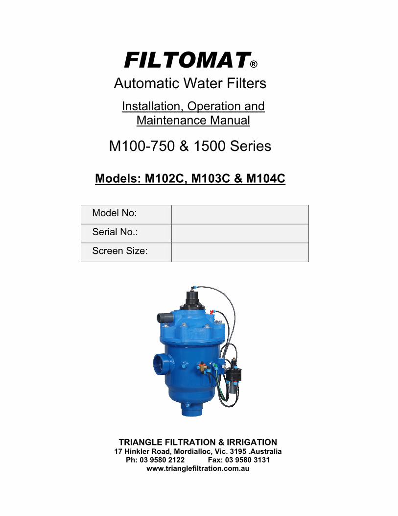
FILTOMAT® Automatic Water Filters
Installation, Operation and Maintenance Manual
M100-750 & 1500 Series
Models: M102C, M103C & M104C
Model No:
Serial No.:
Screen Size:
TRIANGLE FILTRATION & IRRIGATION 17 Hinkler Road, Mordialloc, Vic. 3195 .Australia
Ph: 03 9580 2122 Fax: 03 9580 3131 www.trianglefiltration.com.au
FILTOMAT M100-750 Installation & maintenance – 06.2005 - -
2
TABLE OF CONTENTS
Introduction...............................................................................................................3
Specifications.............................................................................................................4
Safety instructions......................................................................................................5
Dimensional installation diagram ..................................................................................6
Operating principles....................................................................................................7
Installation ................................................................................................................8
Commissioning...........................................................................................................9
Troubleshooting .......................................................................................................10
Adjusting the rinse controller .....................................................................................10
Maintenance ............................................................................................................11
Parts schedule .........................................................................................................12
Parts drawing #1 - Exploded view M102C & M103C .....................................................13
Parts drawing #2 - Cover lid assembly. All Models .......................................................14
Parts drawing #3 - Collector assembly M102C & M103C. ..............................................15
Parts drawing #4 - Exploded view M104C...................................................................16
Parts drawing #5 - Collector assembly M104C.............................................................17
Control system - Hydraulic ........................................................................................18
Screen removal procedure ........................................................................................19
Warranty.................................................................................................................20
Note : Please quote the Filter Model Number, located on the filter housing with your inquiry.
FILTOMAT M100-750 Installation & maintenance – 06.2005 - -
3
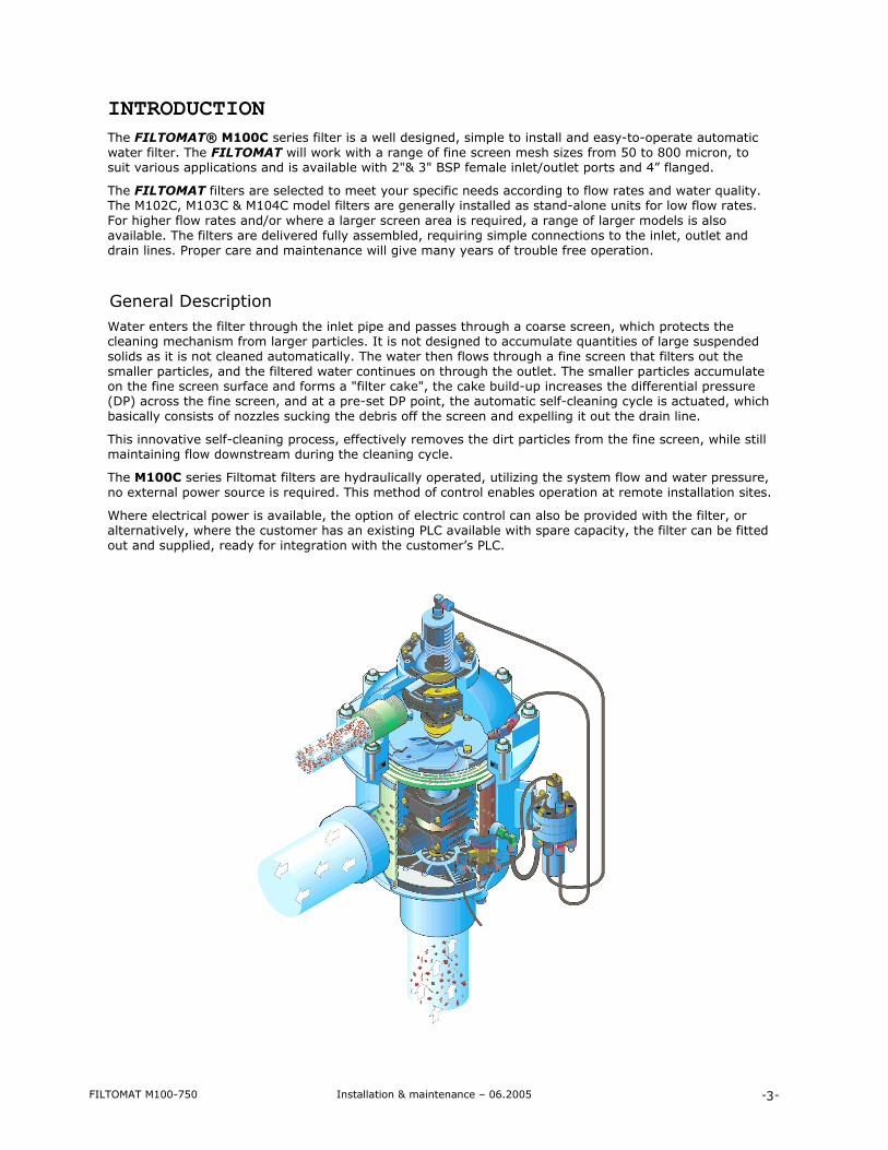
INTRODUCTION The FILTOMAT® M100C series filter is a well designed, simple to install and easy-to-operate automatic water filter. The FILTOMAT will work with a range of fine screen mesh sizes from 50 to 800 micron, to suit various applications and is available with 2"& 3" BSP female inlet/outlet ports and 4” flanged.
The FILTOMAT filters are selected to meet your specific needs according to flow rates and water quality. The M102C, M103C & M104C model filters are generally installed as stand-alone units for low flow rates. For higher flow rates and/or where a larger screen area is required, a range of larger models is also available. The filters are delivered fully assembled, requiring simple connections to the inlet, outlet and drain lines. Proper care and maintenance will give many years of trouble free operation.
General Description Water enters the filter through the inlet pipe and passes through a coarse screen, which protects the cleaning mechanism from larger particles. It is not designed to accumulate quantities of large suspended solids as it is not cleaned automatically. The water then flows through a fine screen that filters out the smaller particles, and the filtered water continues on through the outlet. The smaller particles accumulate on the fine screen surface and forms a "filter cake", the cake build-up increases the differential pressure (DP) across the fine screen, and at a pre-set DP point, the automatic self-cleaning cycle is actuated, which basically consists of nozzles sucking the debris off the screen and expelling it out the drain line.
This innovative self-cleaning process, effectively removes the dirt particles from the fine screen, while still maintaining flow downstream during the cleaning cycle.
The M100C series Filtomat filters are hydraulically operated, utilizing the system flow and water pressure, no external power source is required. This method of control enables operation at remote installation sites.
Where electrical power is available, the option of electric control can also be provided with the filter, or alternatively, where the customer has an existing PLC available with spare capacity, the filter can be fitted out and supplied, ready for integration with the customer’s PLC.

FILTOMAT M100-750 Installation & maintenance – 06.2005 - -
4
SPECIFICATIONS
General
Maximum flow rate M102C = 25 m3/hr M103C = 50 m3/h M104C = 80 m3/h
Consult with your local agent regarding optimum flow, for your application.
Min. working pressure 200 kPa Or lower, if pressure is increased for flushing
Max. working pressure 800 kPa
Flat screen 620cm2 900cm2 for M104C Filter area
Moulded screen 700cm2 950cm2 for M104C
Inlet/Outlet diameter 50, 80 & 100mm (2", 3" & 4”)
2” or 3” BSP Female Thread 4” Table D Flanges
Max. working temperature 550C
Empty / Full weight - M102C - M103C - M104C
22kg / 38kg 25kg / 40kg 35kg / 62kg
Flush data
Drain line 40 mm (1 1/2") Drain line to be 50 N.B. Minimum
Flushing cycle time 10 seconds Depending on the working pressure
Backwash water per cycle 30 litres at 200 kPa
Minimum flow/press. required 14 m3/hr (4 l/sec) Min. of 200 kPa at inlet during flush cycle
Flush criteria Differential pressure (DP) set point at 50 kPa (adjustable)
Construction materials
Filter housing Epoxy-coated mild steel (St.St.316 available on request)
Filter lid High density polypropylene
Coarse screen Reinforced nylon
Fine screen Stainless Steel 316 mesh, PVC or moulded plastic support structure
Cleaning mechanism PVC and Stainless Steel
Motor assembly Reinforced nylon, brass, stainless steel
Control tubing Polyethylene
Seals BUNA-N
Control Brass, Stainless Steel , PVC, Acetal
Filtration screen sizes available Type Moulded screen Flat screen
micron 500 300 200 130 100 80 800 400 200 150 130 100 80 50
mm 0.5 0.3 0.2 0.13 0.1 0.08 0.8 0.4 0.2 0.15 0.13 0.1 0.08 0.05
FILTOMAT M100-750 Installation & maintenance – 06.2005 - -
5
SAFETY INSTRUCTIONS General
Carefully read the installation and operating instructions prior to installing the filter.
While working on the filter, basic safety instructions should be adhered to, to avoid injury to individuals, or property damage in the vicinity.
Note: Once the filter is pressurised, it may commence a self-cleaning cycle automatically, without prior warning.
Modifications to the equipment are not permitted, without written consent from the manufacturer or it’s representative.
Operation, Control and Maintenance Before unscrewing bolts or fittings, make sure the pressure in the filter has been relieved.
Minimize water leakage, where possible, to reduce the danger of slipping, electrocution or damage to the equipment.
Always open and close valves gradually.
Manual cleaning of the filter element using high pressure water, should be performed in accordance with the cleaning system instructions, without endangering personnel or the working area.
Manual cleaning of the filter element using acid or other chemical agents should be performed in accordance with the relevant material safety instructions and without endangering the operator or the working area. Eye protection and suitable gloves must be worn.
Use of Lifting Equipment When using lifting equipment, ensure the item to be lifted is tied securely and in a safe manner.
Avoid working below lifted equipment.
Wear a safety helmet when using lifting equipment.
Beware of overhead electrical power lines.
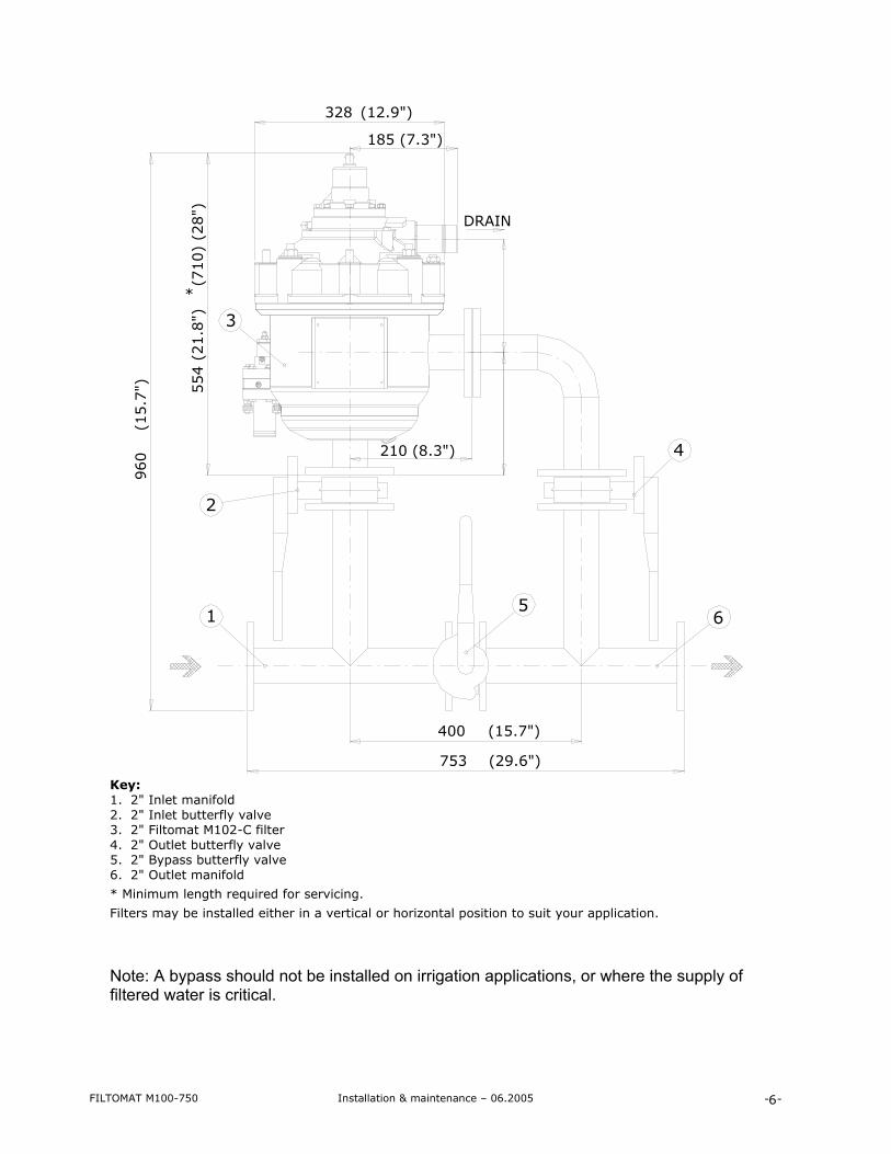
DIMENSIONAL INSTALLATION DRAWING
NOTE: This is a conceptual installation drawing. (piping /valves etc. are not included.)
FILTOMAT M100-750 Installation & maintenance – 06.2005 - -
6
*
753 (29.6")
400 (15.7")
554 (
21.8
") (
710)
(28")
960
(15.7
")
328 (12.9")
210 (8.3")
DRAIN
185 (7.3")
3
2
4
51 6
Key: 1. 2" Inlet manifold 2. 2" Inlet butterfly valve 3. 2" Filtomat M102-C filter 4. 2" Outlet butterfly valve 5. 2" Bypass butterfly valve 6. 2" Outlet manifold
* Minimum length required for servicing.
Filters may be installed either in a vertical or horizontal position to suit your application. Note: A bypass should not be installed on irrigation applications, or where the supply of filtered water is critical.

FILTOMAT M100-750 Installation & maintenance – 06.2005 - -
7
Operating Principles
The automatic self-cleaning cycle is simple and effective, and takes 5-10 seconds, with only minor interruption, if any, to the downstream water supply. (this is relative to the water supply/pump performance available).
Water flows from the inlet through the coarse and fine screens to the outlet. The filter cake builds up on the fine screen and when it reaches the pre-set differential pressure (DP) of 50kPa, the rinse controller is actuated and starts the cleaning cycle.
The exhaust valve opens to atmosphere, creating a pressure drop in the rotor chamber, which creates suction at the nozzle tips, removing the dirt built up on the screen surface.
The backflush water flows through the nozzles to the collector pipe and via the rotor to the exhaust valve and out through the drain. The escaping water flowing through the rotor forces the dirt collector assembly to spin, and move up vertically at the same time, subsequently the nozzles are sucking the dirt off the total screen area. When the first stroke is completed, the exhaust valve closes for a few seconds, and the rinse controller activates the second backflush stroke (downward). The dirt collector assembly rotates and moves downward returning to its original position and the exhaust valve shuts.
The two stroke helical movement of the dirt collector assembly as described, ensures that the nozzles sweep the entire fine screen surface twice per cleaning cycle.
This self-cleaning process takes approximately 10 seconds, depending on the operating pressure.
Exhaust valve
Rotor chamber
Rinse controller
Drain
Rotor
Fine screen
Outlet
Nozzles
Inlet
Dirt collector
Collector pipe

FILTOMAT M100-750 Installation & maintenance – 06.2005 - -
8
INSTALLATION Read these instructions carefully before installing and operating the filter. Design Recommendations The filter can be mounted vertically or horizontally.
For a prolonged high flow and low pressure condition, due to the filling of pipelines on start up, it is recommended a pressure sustaining valve (PSV) is installed downstream of the filter. The PSV will ensure backpressure on the filter, and controlled filling of the pipeline.
The filter inlet pressure should not drop below 200 kPa during the rinse cycle. If this cannot be ensured, consult your local dealer or manufacturer’s agent.
If water supply is essential at all times, it is recommended that a manual or automatic by-pass be installed.
The drain line should be 50 mm (2”) minimum, and open to atmosphere, to minimise backpressure on the filter. Avoid running the drain line more than 12 metres or placing it on a rising slope.
Secure the drain line to prevent movement/damage during the rinse cycle.
Minimise bends and elbows on the drain line. Note: The complete cover lid assembly can be removed and rotated at 90º intervals to allow a more direct route to your drain point. The filter drain line outlet, should not be located near the pump suction inlet.
The Rinse Controller has a 1”BSP Fem. (25 mm) drain port on the bottom which bleeds about ½ litre per backflush cycle. This can also be connected to the main drain line, preferably at an angle to eliminate any backflow or backpressure.
We recommend a mechanical non-return valve be installed downstream of the filter.
The pressure gauge supplied, is to be mounted on the three-way valve on the filter.
Check that there is sufficient space to remove the cover assembly and the screen from the filter for servicing and troubleshooting.
Preparations for Installation
Provide suitable lighting around the filter area, for good visibility and safe maintenance.
Arrange suitable platforms and safety barriers where required, for safe access to the filter.
It is recommended a mechanical non-return valve be installed downstream of the filter to prevent backflow damage to the screen.
Allow enough space for dismantling and maintenance of the filter.
Installation Procedure Ensure the direction of flow is according to the arrows marked on the filter housing. 1. Connect a minimum of 2" (50mm) pipe to the drain. The drain line should be installed so that it creates
minimal resistance to a flow of 20m3/h. Water should flow freely from the drain line to atmosphere.
2. Connect a minimum of 1" (25mm) flexible tube to the rinse controller drain port. Ensure this drain line is open to atmosphere.
IMPORTANT!! Prevent static backpressure or reverse flow through the filter. Install a manual isolating valve after (downstream) the filter. Install a manual isolating valve before (upstream) the filter if there is any static head on the
inlet side. If the inlet operating pressure falls below 250 kPa install a pressure sustaining valve (PSV)
after the filter. NOTE: Once pressurized the filter may flush automatically, without prior warning.
FILTOMAT M100-750 Installation & maintenance – 06.2005 - -
9
COMMISIONING Before using the filter, go through the following check-list carefully. No special training is required to carry out these activities.
Check that the filter is mounted in the correct flow direction.
Check that all the control tubes are connected properly and that all connections are tight.
Check that the three-way mini-valve is turned to the automatic position. The arrow on the knob should point to AUTO, and the red sticker on the filter.
The nominal diameter of the drainpipe should be 2" (50mm), do not restrict the drain line, it should be open to atmosphere.
Shut the upstream and downstream isolation valves.
Check that there is sufficient space to remove the cover lid assembly and the screen from the filter for servicing/troubleshooting.
Check that the drain line has a union fitted, to allow removal of the cover lid assembly for servicing.
Check that the pressure gauge has been fitted on the brass 3-way valve.
GETTING STARTED First operation of filter
After completing the preparation check-list above, perform the following steps:
1. Slowly open the inlet valve at the filter, and pressurize the vessel.
2. Check for leaks and repair if necessary.
3. Check that the minimum inlet pressure remains 200 kPa or higher.
4. Start a manual flush by turning the three-way valve to the OPEN position for a few seconds, and then turn it back to AUTO. You may have to cycle the unit several times to clear the lines of air.
5. Slowly open the outlet valve at the filter. If you are filling the pipeline/s after the filter, throttle this valve and maintain pressure (above 200 kPa) at the filter, until the lines are full and pressurised. (unless a pressure sustaining valve is fitted to perform this function.)
6. If there is a by-pass valve, close it slowly.
7. Ensure the flow through the filter does not exceed the filter’s maximum flow rate.
8. Start a manual flush by turning the three-way valve to the OPEN position for a few seconds, and then turn it back to AUTO. The cycle duration is approx. 5-10 seconds.
9. During the self-cleaning cycle, check the pressure at the filter inlet does not drop below 200 kPa, and check the pressure in the rotor chamber.
NOTE: The minimum pressure in the rotor chamber should be 150 kPa lower than the inlet pressure.

FILTOMAT M100-750 Installation & maintenance – 06.2005 - -
10
Problem Possible Cause Solution
Pressure differential is not correct Pump not running 3-way manual flush valve in open/closed position
Perform a manual flush as follows: 1. Close the filter outlet valve 2. Check that the filter outlet and inlet
pressures are equal 3. Perform a manual flush as in item 8,
page 9. 4. Check the pressures at the inlet valve
and in the rotor chamber Rinse controller dripper leaking water constantly.
Filter may be blocked, proceed as per above to clear filter.
Filter not cleaning
Rinse controller has been adjusted incorrectly
Check and re-adjust screw on rinse controller (see below)
Excessive pressure in the rotor chamber
Drain pipes are not clear, or too small in diameter.
Check if drain lines are clear. If necessary replace with a larger (diameter) flush drain line, or shorten the existing lines.
Insufficient inlet pressure (less than 200 kPa)
Inlet valves not fully open Pump not running.
Open inlet valves to maximum. Increase the inlet pressure or throttle the outlet to increase pressure during the cleaning cycle. Fit PSV valve
Coarse filter is blocked Check coarse filter Pressure differential exceeds 70 kPa during normal operation
Fine screen has build-up of material. Rinse controller needs adjusting
Remove screen and high press. clean. Adjust rinse controller (see below) Check for blockage at high pressure sensing line no.7 or no.5 low press. line
Inlet lines blocked Check inlet lines Water does not flow through the filter
Isolating valves are closed Pump not running/lost prime Filter blocked
Open isolating valves Check pump/foot valve Repeat steps 1-4 as above at para.1
ADJUSTING THE RINSE CONTROLLER NOTE: Improper adjusting of the rinse controller may cause the filter to malfunction.
1. Disconnect the 1”(25mm) rinse controller drain line.
2. Flush the filter manually, using the 3-way valve as per item 8, Page 9 to ensure you start with a clean filter.
3. Loosen the locking nut on the long nose (1) and loosen the adjusting screw (2), anticlockwise, slowly until a self-cleaning cycle begins.
4. Turn the adjusting screw (2) clockwise 1.5 turns, and then tighten the locking nut (1). This adjusts the rinse controller for a differential pressure of approx. 50 kPa.
5. Observe at least one automatic self-cleaning cycle, if possible, checking the differential set point with the gauge on the 3–way valve.
FILTOMAT M100-750 Installation & maintenance – 06.2005 - -
11
MAINTENANCE Before shutting down the filter, flush the filter manually via the 3-way valve. By doing this you can observe the cleaning efficiency of the unit. By checking the inlet/outlet pressure on the gauge. NOTE: De-pressurize the filter before disassembly or maintenance (close inlet, and then outlet valve), then manually flush the unit to release the pressure from the vessel, check the pressure gauge to make sure all pressure has been relieved.
Checking the Filter
1. Remove the filter cover lid assembly by unscrewing the 8 nuts. (Note: a thinner nut is fitted under the drain line).
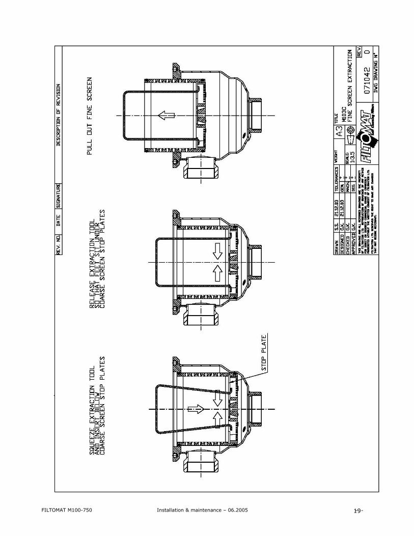
2. Extract the fine screen using the screen puller provided,(refer to page 19) and clean if necessary, the screen is only retained by the o-rings on the outside diameter. Cleaning is best achieved using a high pressure water cleaner (Gernie), only spray the screen from the inside out !. If there is an iron oxide or calcium carbonate build up on the mesh, you will need to clean it with a diluted acid solution (1:10 hydrochloric acid:water). Make sure suitable protective equipment is worn, a 5 minute soaking and then pressure clean as above. (repeat if necessary). Avoid long periods in the acid solution, as this will ruin the screen.
3. Check the coarse screen and clean if necessary.
4. Check the O-rings of the fine screen, replace if necessary and apply suitable lubricant.
5. Install the fine screen, pushing it home on the o-rings.
6. Fit the cover lid assembly, carefully aligning the dirt collector shaft into the bearing and fit and fasten the 8 nuts, fit the thin nut first. Just nipping them up is enough!
7. Perform First Operation of Filter as on page 9.
Decommissioning If the filter is to be shut down for any period of time, e.g. The end of an irrigation season the following procedure should be followed:
1. With the pump on, close the outlet isolating valve completely and perform two manual rinses.
2. Turn the pump off.
3. Close the inlet valve if fitted.
4. To restart the system open the inlet valve and do the same as above, then open the downstream valve slowly with the valve open enough to re-charge the down stream pipework, (not required if a PSV valve is fitted) maintain at least 200 kPa backpressure on the filter while doing this. Once the pipeline has been pressurised open the valve fully.
Note: If in doubt, please call us for assistance.
FILTOMAT M100-750 Installation & maintenance – 06.2005 - -
12
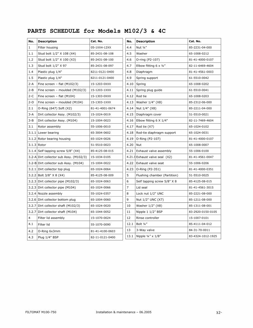
PARTS SCHEDULE for Models M102/3 & 4C
No. Description Cat. No.
1 Filter housing 05-1XX4-12XX
1.1 Stud bolt 1/2" X 108 (X4) 85-2431-08-108
1.2 Stud bolt 1/2" X 100 (X3) 85-2431-08-100
1.3 Stud bolt 1/2" X 97 85-2431-08-097
1.4 Plastic plug 1/4" 8211-0121-0400
1.5 Plastic plug 1/4" 8211-0121-0400
2-A Fine screen – flat (M102/3) 15-1203-0XXX
2-B Fine screen – moulded (M102/3) 15-1203-1XXX
2-C Fine screen – flat (M104) 15-1303-0XXX
2-D Fine screen – moulded (M104) 15-1303-1XXX
2.1 O-Ring (647) Soft (X2) 81-41-4001-0674
3-A Dirt collector Assy. (M102/3) 15-1024-0019
3-B Dirt collector Assy. (M104) 15-1004-0023
3.1 Rotor assembly 55-1006-0010
3.1.1 Lower bearing 65-3004-0602
3.1.2 Rotor bearing housing 65-1024-0026
3.1.3 Rotor 51-5510-0023
3.1.4 Self tapping screw 5/8" (X4) 85-4125-08-015
3.2-A Dirt collector sub Assy. (M102/3) 15-1034-0105
3.2-B Dirt collector sub Assy. (M104) 15-1004-0022
3.2.1 Dirt collector top plug 65-1024-0064
3.2.2 Bolt 3/8" X 8 (X4) 85-4125-08-009
3.2.3 Dirt collector pipe (M102/3) 65-1024-0063
3.2.3 Dirt collector pipe (M104) 65-1024-0066
3.2.4 Nozzle assembly 55-1024-0357
3.2.6 Dirt collector bottom plug 65-1004-0060
3.2.7 Dirt collector shaft (M102/3) 65-1024-0020
3.2.7 Dirt collector shaft (M104) 65-1044-0052
4 Filter lid assembly 15-1070-0024
4.1 Filter lid 55-1070-0090
4.2 O-Ring 6x3mm 81-41-4100-0603
4.3 Plug 1/4" BSP 82-11-0121-0400
No. Description Cat. No.
4.4 Nut ¼” 85-2231-04-000
4.5 Washer 65-1008-0212
4.6 O-ring (P2-107) 81-41-4000-0107
4.7 Elbow fitting 6 x ¼” 82-11-6469-4604
4.8 Diaphragm 81-41-4561-0003
4.9 Spring support 61-5510-0042
4.10 Spring 65-1008-0202
4.11 Spring plug guide 61-5510-0041
4.12 Rod tie 65-1008-0203
4.13 Washer 1/4" (X8) 85-2312-06-000
4.14 Nut 1/4" (X8) 85-2211-04-000
4.15 Diaphragm cover 51-5510-0021
4.16 Elbow fitting 6 X 1/4" 82-11-7469-4604
4.17 Rod tie (X7) 65-1024-0102
4.18 Rod-tie diaphragm support 65-1024-0031
4.19 O-Ring (P2-107) 81-41-4000-0107
4.20 Nut 65-1008-0007
4.21 Exhaust valve assembly 55-1006-0100
4.21.1 Exhaust valve seal (X2) 81-41-4561-0047
4.22 Exhaust valve seat 55-1006-0206
4.23 O-Ring (P2-351) 81-41-4000-0351
5 Flushing chamber (Partition) 51-5510-0025
6 Self tapping screw 5/8" X 8 85-4125-08-015
7 Lid seal 81-41-4561-3015
8 Lock nut 1/2" UNC 85-2221-08-000
9 Nut 1/2" UNC (X7) 85-1211-08-000
10 Washer 1/2" (X8) 85-1311-08-001
11 Nipple 1 1/2” BSP 83-2920-0150-0105
12 Rinse controller 15-1007-0101
12.1 Bolt ¼” 85-4111-04-012
13 3-Way valve 84-31-70-0011
13.1 Nipple ¼” x 1/8” 83-4324-1012-1925

FILTOMAT M100-750 Installation & maintenance – 06.2005 - -
13
PARTS DRAWING #1 – Filter Exploded View M102/3

FILTOMAT M100-750 Installation & maintenance – 06.2005 - -
14
PARTS DRAWING #2 – Cover Lid Assembly M102/3&4

FILTOMAT M100-750 Installation & maintenance – 06.2005 - -
15
PARTS DRAWING #3 - Collector/Rotor Assembly M102/3

FILTOMAT M100-750 Installation & maintenance – 06.2005 - -
16
PARTS DRAWING #4 – Exploded View – M104C

FILTOMAT M100-750 Installation & maintenance – 06.2005 - -
17
DRAWING #5 – Collector/Turbine Assembly – M104C
FILTOMAT M100-750 Installation & maintenance – 06.2005 - -
18
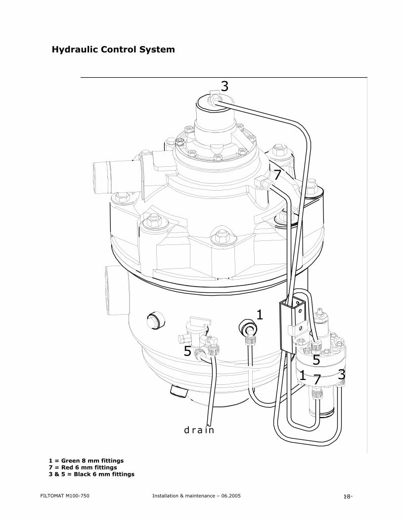
Hydraulic Control System 1 = Green 8 mm fittings 7 = Red 6 mm fittings 3 & 5 = Black 6 mm fittings
d r a in
3
7
1
5
1
5
7 3
FILTOMAT M100-750 Installation & maintenance – 06.2005 - -
19

FILTOMAT M100-750 Installation & maintenance – 06.2005 - -
20
Warranty The manufacturer warrants the product only against defects in material and workmanship for (1) year from date of installation. This limited warranty is valid only when the product is used in accordance with the manufacturer’s standards and instructions and on condition that the customer fulfills his/her obligations set forth in this manual. The manufacturer’s liability is limited to the replacement of defective parts with new or rebuilt parts, free of charge. This warranty is extended only to the original purchaser. A purchase receipt or other proof of date of original purchase is required before warranty performance is rendered. This warranty only covers failures due to defects in materials or workmanship, which occur during normal use. It does not cover damage caused by accidents, misuse, abuse, neglect, mishandling, misapplication, alteration, modification or service by anyone other than the manufacturer or any person/agent authorized by the manufacturer.
The manufacturer is not liable for incidental or consequential damages resulting from the use of this product or arising out of any breach of this warranty. All express and implied warranties, including the warranties of merchantability and fitness for a particular purpose, are limited to the applicable warranty period set forth above. Faulty replaced parts are to be returned to Triangle Filtration for inspection and assessment, so they in turn can claim warranty replacements from the manufacturer. If you have any questions, contact your local dealer or our service department.