manual logos part a: installation of the logos · part a: installation of the logos ... umc hybrid...
TRANSCRIPT
Manual Logos
EELA AUDIO Parmentierweg 3 1 Rev. 6 (July 2001)5657 EH Eindhoven, the Netherlands Main v1.43
PART A: INSTALLATION OF THE LOGOS
1 The desktop console ............................................................................................................ 2
1.1 Outlook --------------------------------------------------------------------------------------------------------------------2
1.2 Fader section ------------------------------------------------------------------------------------------------------------3
1.3 Monitor section ----------------------------------------------------------------------------------------------------------3
1.4 Function keys------------------------------------------------------------------------------------------------------------4
1.5 Numeric keypad---------------------------------------------------------------------------------------------------------4
1.6 Transport control section ---------------------------------------------------------------------------------------------5
1.7 Jog / shuttle wheel------------------------------------------------------------------------------------------------------5
2 The rack-unit (D902).............................................................................................................. 6
2.1 Front side connectors--------------------------------------------------------------------------------------------------6
2.2 Rear side connectors --------------------------------------------------------------------------------------------------7
3 LogosTool software .............................................................................................................. 9
3.1 Connect procedure-----------------------------------------------------------------------------------------------------9
3.2 Toolbar ------------------------------------------------------------------------------------------------------------------10
3.3 Tabs----------------------------------------------------------------------------------------------------------------------11
PART B: OPERATION OF THE LOGOS
4 Start-up of the Logos..........................................................................................................16
5 Source configuration..........................................................................................................17
5.1 Gain ----------------------------------------------------------------------------------------------------------------------17
5.2 Balance or Pan--------------------------------------------------------------------------------------------------------17
6 Microphone adjustments ...................................................................................................18
6.1 Accessing the menu--------------------------------------------------------------------------------------------------18
6.2 Phantom power -------------------------------------------------------------------------------------------------------18
6.3 HighPass filter ---------------------------------------------------------------------------------------------------------18
6.4 Insert bypass ----------------------------------------------------------------------------------------------------------19
6.5 Compressor / Limiter-------------------------------------------------------------------------------------------------19
6.6 Ducker-------------------------------------------------------------------------------------------------------------------19
6.7 MonitorSel --------------------------------------------------------------------------------------------------------------20
Appendix 1: LOGOS Specifications ........................................................................................21
Appendix 2: Description sub-D25 and sub-D9 pinning .......................................................22
Appendix 3: UMC Hybrid connection (older version) ..........................................................23
Appendix 4: UMC Hybrid connection (new version) ............................................................24
Appendix 5: RS-232 cable Logos.............................................................................................25
Appendix 6: Block Diagram ......................................................................................................26
Index ..............................................................................................................................................27
interstagePhistersvej 31, 2900 Hellerup, Danmark
Telefon 3946 0000, fax 3946 0040www.interstage.dk
- pro audio with a smile
Manual Logos
EELA AUDIO Parmentierweg 3 2 Rev. 6 (July 2001)5657 EH Eindhoven, the Netherlands Main v1.43
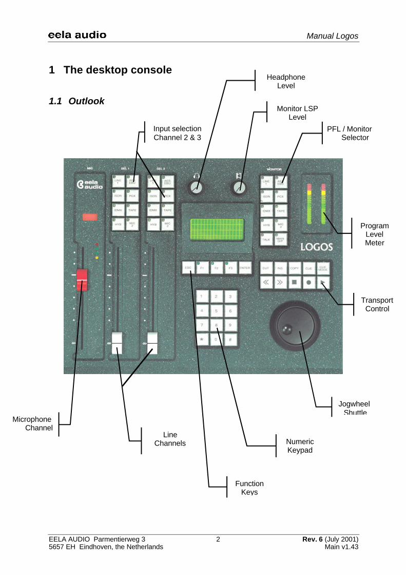
HeadphonLevel
1 The desktop console
1.1 Outlook
ProgramLevelMeter
PFL / MonitorSelector
Monitor LSPLevel
Input selectionChannel 2 & 3
TransportControl
NumericKeypad
LineChannels
JogwheelShuttle
MicrophoneChannel
FunctionKeys
HeadphoneLevel

Manual Logos
EELA AUDIO Parmentierweg 3 3 Rev. 6 (July 2001)5657 EH Eindhoven, the Netherlands Main v1.43
1.2 Fader sectionMicrophone channelThe left fader is always the main microphone channel. If configured as a Controlroommicrophone (factory default setting), the monitor loudspeakers are muted and the red-lightindicator is switched on upon opening the microphone fader. If the microphone is configuredas Studio microphone this indicator will stay dark and the monitor loudspeakers are notmuted.
Upon opening this main microphone fader the monitor will automatically switch to mainoutput (factory default setting) or a pre-defined source as set in the LogosTool software or onthe desktop console. See also chapter 3.
The LED’s next to the microphone fader are an indication for the build in limiter/compressor.See paragraph 6.5 for more information about the settings of the compressor/limiter and theother parameters for the microphone channel.
Line channelsAbove each of the two line channel faders are eight pushbuttons with LED indication for thesource input selection. When the fader is closed, a source will be assigned immediately butonly accepted when the other fader does not select that source. In that case the button willnot be active.
An open fader can do only pre-selection. The newly selected source is pre-selected bypressing a source button and then the LED will start blinking. Upon closing the fader thenewly selected source will become active on that channel directly. If a source is pre-selectedon both faders the channel fader that is closed first will take over that source and the pre-selection on the other fader will be switched off.
A fader start/stop is coupled to the source and becomes active if the source is selected on afader, depending on the LogosTool configuration settings. Pre-selecting a source means thata fader start/stop will be active also as soon as the fader is closed and opened again (andthe source is activated).
1.3 Monitor sectionLevel control for the monitor speakersThe monitor level pot can adjust the level for monitor speakers. If the control roommicrophone fader is opened the loudspeakers are muted. Using the talkback function willcause the speakers to dim by approx. 10dB.
Headphone volumeThe headphone level pot can adjust the headphone level.
PFL / Monitor selector and talkbackThe first eight buttons are used as PFL / Monitor selector, presenting the same sources ason the input selectors assigned to it.
Manual Logos
EELA AUDIO Parmentierweg 3 4 Rev. 6 (July 2001)5657 EH Eindhoven, the Netherlands Main v1.43
Holding the button down longer (long-press function) activates the source dependent set-upmenu. In this menu you can set both gain and balance level for that source.
Pushing the button shortly (short-press function) activates the prefade listening (PFL). Thespeakers, headphone and program level meter reproduce the signal of the selected source.
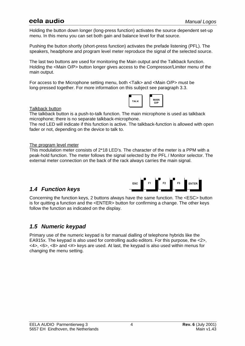
The last two buttons are used for monitoring the Main output and the Talkback function.Holding the <Main O/P> button longer gives access to the Compressor/Limiter menu of themain output.
For access to the Microphone setting menu, both <Talk> and <Main O/P> must belong-pressed together. For more information on this subject see paragraph 3.3.
Talkback buttonThe talkback button is a push-to-talk function. The main microphone is used as talkbackmicrophone; there is no separate talkback-microphone.The red LED will indicate if this function is active. The talkback-function is allowed with openfader or not, depending on the device to talk to.
The program level meterThis modulation meter consists of 2*18 LED’s. The character of the meter is a PPM with apeak-hold function. The meter follows the signal selected by the PFL / Monitor selector. Theexternal meter connection on the back of the rack always carries the main signal.
1.4 Function keysConcerning the function keys, 2 buttons always have the same function. The <ESC> buttonis for quitting a function and the <ENTER> button for confirming a change. The other keysfollow the function as indicated on the display.
1.5 Numeric keypadPrimary use of the numeric keypad is for manual dialling of telephone hybrids like theEA915x. The keypad is also used for controlling audio editors. For this purpose, the <2>,<4>, <6>, <8> and <#> keys are used. At last, the keypad is also used within menus forchanging the menu setting.
TALKMAINO/P
Manual Logos
EELA AUDIO Parmentierweg 3 5 Rev. 6 (July 2001)5657 EH Eindhoven, the Netherlands Main v1.43
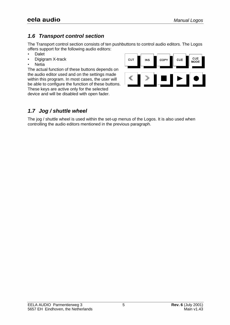
1.6 Transport control sectionThe Transport control section consists of ten pushbuttons to control audio editors. The Logosoffers support for the following audio editors:• Dalet• Digigram X-track• NetiaThe actual function of these buttons depends onthe audio editor used and on the settings madewithin this program. In most cases, the user willbe able to configure the function of these buttons.These keys are active only for the selecteddevice and will be disabled with open fader.
1.7 Jog / shuttle wheelThe jog / shuttle wheel is used within the set-up menus of the Logos. It is also used whencontrolling the audio editors mentioned in the previous paragraph.
Manual Logos
EELA AUDIO Parmentierweg 3 6 Rev. 6 (July 2001)5657 EH Eindhoven, the Netherlands Main v1.43
2 The rack-unit (D902)
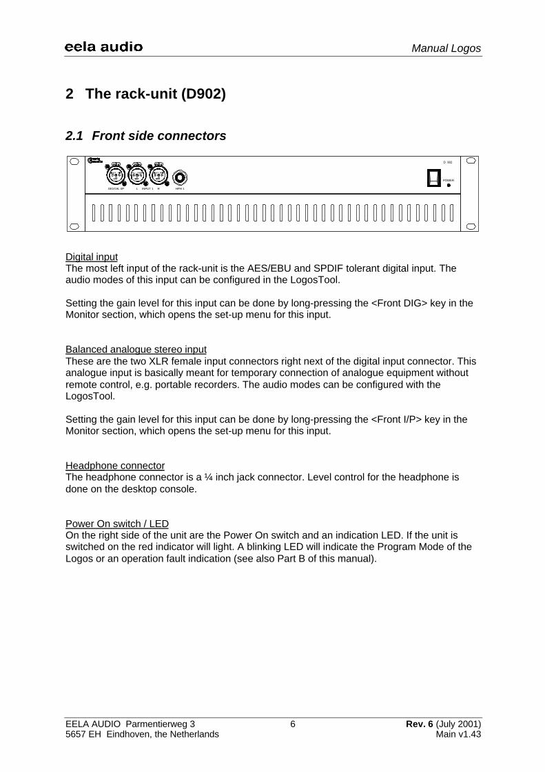
2.1 Front side connectors
DIGITAL I/P L INPUT 1 R HPH 1
POWER
D 902
Digital inputThe most left input of the rack-unit is the AES/EBU and SPDIF tolerant digital input. Theaudio modes of this input can be configured in the LogosTool.
Setting the gain level for this input can be done by long-pressing the <Front DIG> key in theMonitor section, which opens the set-up menu for this input.
Balanced analogue stereo inputThese are the two XLR female input connectors right next of the digital input connector. Thisanalogue input is basically meant for temporary connection of analogue equipment withoutremote control, e.g. portable recorders. The audio modes can be configured with theLogosTool.
Setting the gain level for this input can be done by long-pressing the <Front I/P> key in theMonitor section, which opens the set-up menu for this input.
Headphone connectorThe headphone connector is a ¼ inch jack connector. Level control for the headphone isdone on the desktop console.
Power On switch / LEDOn the right side of the unit are the Power On switch and an indication LED. If the unit isswitched on the red indicator will light. A blinking LED will indicate the Program Mode of theLogos or an operation fault indication (see also Part B of this manual).

Manual Logos
EELA AUDIO Parmentierweg 3 7 Rev. 6 (July 2001)5657 EH Eindhoven, the Netherlands Main v1.43
2.2 Rear side connectors
Mains supplyThe mains inlet connector is a Neutrik PowerCon connector (NAC 3FCA, blue). Thisconnector provides a safe and reliable mains connection without the risk of accidentallydisconnection, as with standard IEC types. Mains inputs ranging from 90 VAC to 264 VACare accepted.
Inside the build in power supply there is a F2,5A/250V fuse. If this fuse needs to be replaced,replace it only with Shurter SP0001.1008 or Littelfuse 21602.5
Microphone and insert inputMicrophone input is available on a XLR Female connector. In the microphone menu 48 Voltphantom powering can be switched On or Off to power condenser microphones.Holding down the <Main> and <Talkback> buttons together (longpress function) givesaccess the microphone set-up menu.
The insertion point has a ¼ inch jack connector. The level of the insertion point depends onthe pre-gain setting of the Microphone input. The Microphone signal is pre-amplified 40 dB or60 dB. Adjusting the pre-gain of the Microphone input therefore can cause theinsertion point level to raise 20 dB!! This will happen at approx. 50 dB pre-gain.
Input / output modulesA maximum of 6 stereo input / output, analogue or digital, modules can be plugged in.
The analogue modules can be used in combination with e.g. a telephone hybrid. A maximumof 2 telephone hybrids can be connected, because the Logos provides 2 cleanfeeds,required for a telephone connection. When a telephone hybrid is selected to be the inputsource of a module, the output signal of that module will automatically change from Main toCleanfeed.
The digital modules have a build-in input Sample Rate Converter. The output sample rate is48 kHz. All digital I/O is according to the AES/EBU standard. For SPDIF, an adapter cable forshort distances will work. For longer distances, an impedance-corrected adapter is preferred.
Remark:The digital module is also needed when a digital output is required, as the basic Logos unitdoes not provide a digital output. The input of this module can be used for a play-only devicelike a CD player.
Manual Logos
EELA AUDIO Parmentierweg 3 8 Rev. 6 (July 2001)5657 EH Eindhoven, the Netherlands Main v1.43
On all modules, inputs are always combined with outputs on the one sub-D25 femalemultipin connector on the board. Also signalling, fader start/stop (GPIO) is present on thisconnector.
In general: GPI are inputs low active and GPO are isolated optocoupler outputs for collectorand emitter (with If max= 30 mA, max. 70 Volts).
External meter outputThis ¼ inch jack connector provides an output to connect an external modulation meter (e.g.RTW). This connector always carries the main output signal at a nominal signal level of+6dB.
Loudspeaker outputsMonitor output is loudspeaker line-level, asymmetrical stereo, on a ¼ inch jack. Activespeakers can be connected directly. The volume control for the loudspeakers is on the Logoscontrol panel.
Main outputThese are two symmetrical analogue outputs for left and right on XLR male connectors, to beused as feed for e.g. a transmitter. The Main signal can also be present on the sub-D25multipin connectors of the input boards, depending on the LogosTool configuration (seeChapter 3).
Sub-D9 GPI connectorA 9-pole sub-D9 connector is present with a number of signal input and outputs. Theseinputs and outputs can be used for e.g. an ON AIR bulb or Cough button. The function of theinputs and outputs can be programmed with the LogosTool software.
RS232 connectorThe other 9-pole sub-D connector is a RS232 serial port, to connect the rack unit to the PC.In normal operation the Audio Editor is controlled by means of this port. The same PC canalso be used to run the LogosTool software.The connection is a straight 1 to 1 connection, with TX on pin 2, RX on pin 3 and GND to pin5. For this purpose, a fully wired cable can also be used.
Remark: to avoid damage to the electronics due to Electronic Static Discharge (ESD),both the mains of the PC and the Logos have to be plugged into an earthed outlet,before connecting the serial communication cable.
Console connectorThis connector is used for connecting the Logos desktop console to the rack unit. Thisspecially wired cable carries the serial data and power supply for the console.
Optionally, an extended 5 meter cable can be ordered.
Manual Logos
EELA AUDIO Parmentierweg 3 9 Rev. 6 (July 2001)5657 EH Eindhoven, the Netherlands Main v1.43
3 LogosTool software
LogosTool is a Windows computer program for Windows 95/98 and NT clients. To use thesoftware, connect a computer with the Logos (rackunit). The computer should be connectedwith the ‘RS232’ port of the Logos. The characteristics of the communication between PCand the Logos are: 9600 baud, 8 databits, no parity, no handshake.
Described is version 1.0.0 (build 18) to be used with Logos firmware version 1.43.Configurations made with versions of the LogosTool older then 1.0.0.18 in combination withfirmware versions older then V1.40, are no longer useable. So make notes of all presentconfigurations before updating. When the update has taken place, the configuration has tobe made manually. From now on these setting can be saved in config file (*.cfg).
Please contact Eela Audio if you have questions regarding other software versions.
3.1 Connect procedureFor checking or updating firmware or for changing the configuration settings you must do thefollowing:1. Connect the mains of the PC and the Logos using an earthed outlet (to avoid ESD
problems)2. Connect your computer to the D902 rack unit with the 1-to-1 RS232 cable3. Start the LogosTool4. Select ‘Reconnect’ in the ‘Action’ menu5. Turn ON (or first OFF and then ON) the Logos rack unit6. If the connection is okay, the message ‘Connected’ appears at the bottom of the status
line. Mention the message ‘Firmware version Vx.x’.
Updating firmwareAfter connecting the PC with the Logos, select the update button or 'Update firmware' in the'Action' menu. This will start the procedure to update the firmware of the Logos:1. First of all the old firmware is read;2. You will get the question where to store the old firmware on disk;3. The program will ask you for a name for the old firmware;4. The program will ask you for the location of the new firmware file;5. Then the new firmware is loaded into the Logos;
Changing the configurationAfter connecting, the configuration of the Logos can be changed. This can be done bystarting a new configuration file, or by first read out the current configuration of the Logos.
Manual Logos
EELA AUDIO Parmentierweg 3 10 Rev. 6 (July 2001)5657 EH Eindhoven, the Netherlands Main v1.43
3.2 Toolbar
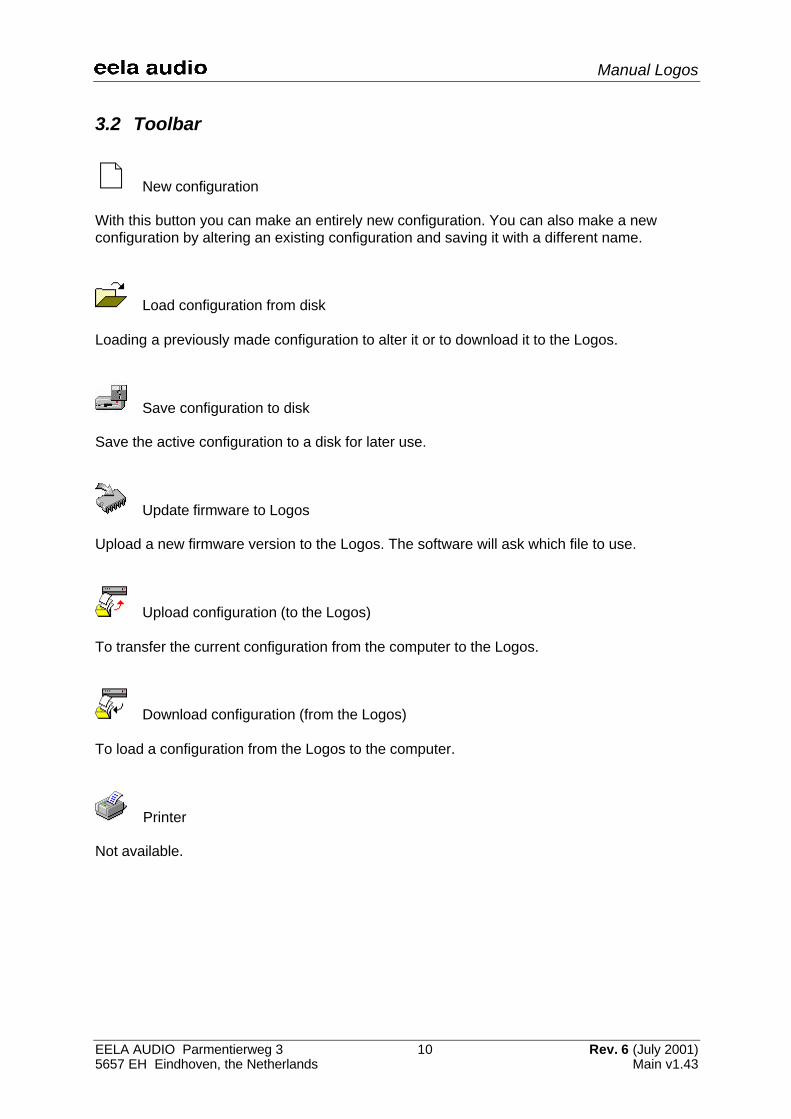
New configuration
With this button you can make an entirely new configuration. You can also make a newconfiguration by altering an existing configuration and saving it with a different name.
Load configuration from disk
Loading a previously made configuration to alter it or to download it to the Logos.
Save configuration to disk
Save the active configuration to a disk for later use.
Update firmware to Logos
Upload a new firmware version to the Logos. The software will ask which file to use.
Upload configuration (to the Logos)
To transfer the current configuration from the computer to the Logos.
Download configuration (from the Logos)
To load a configuration from the Logos to the computer.
Printer
Not available.
Manual Logos
EELA AUDIO Parmentierweg 3 11 Rev. 6 (July 2001)5657 EH Eindhoven, the Netherlands Main v1.43
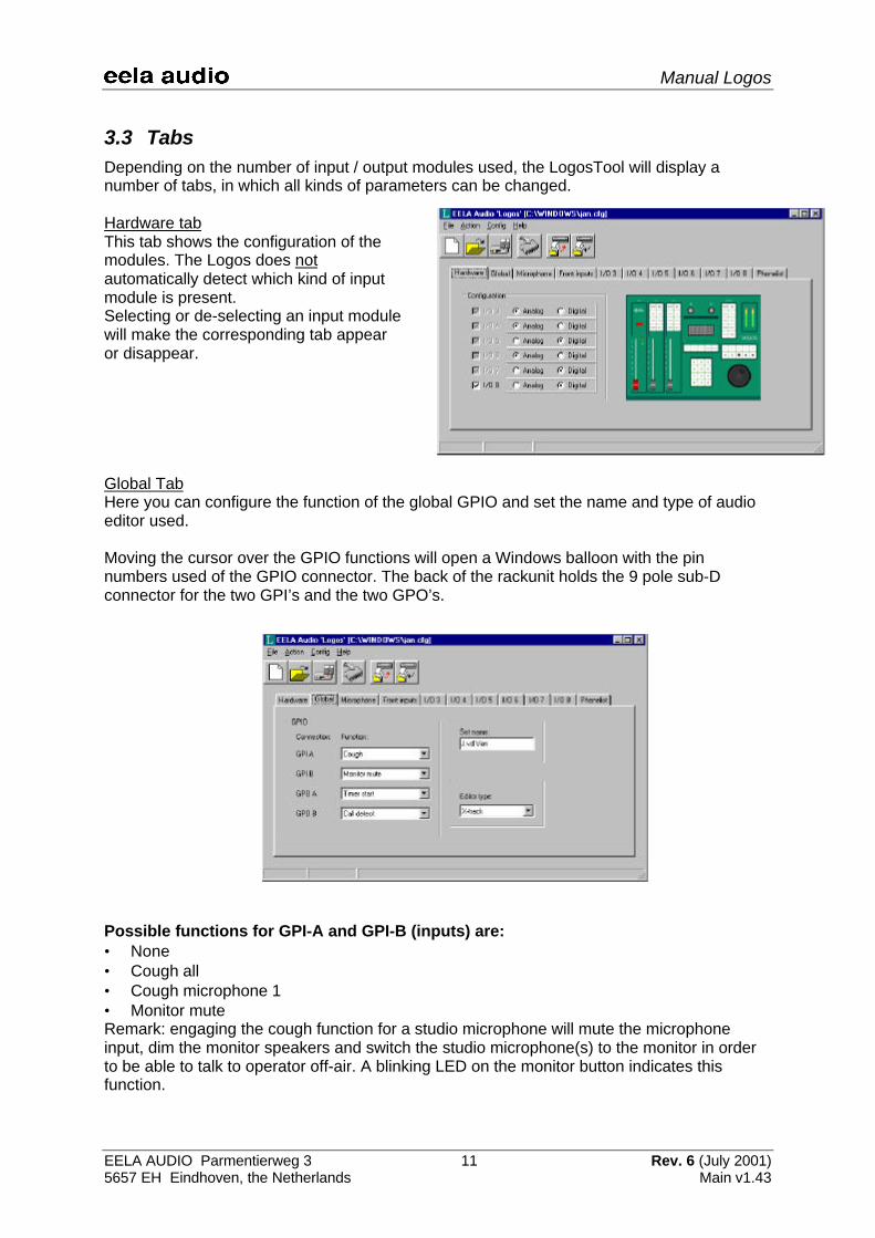
3.3 TabsDepending on the number of input / output modules used, the LogosTool will display anumber of tabs, in which all kinds of parameters can be changed.
Hardware tabThis tab shows the configuration of themodules. The Logos does notautomatically detect which kind of inputmodule is present.Selecting or de-selecting an input modulewill make the corresponding tab appearor disappear.
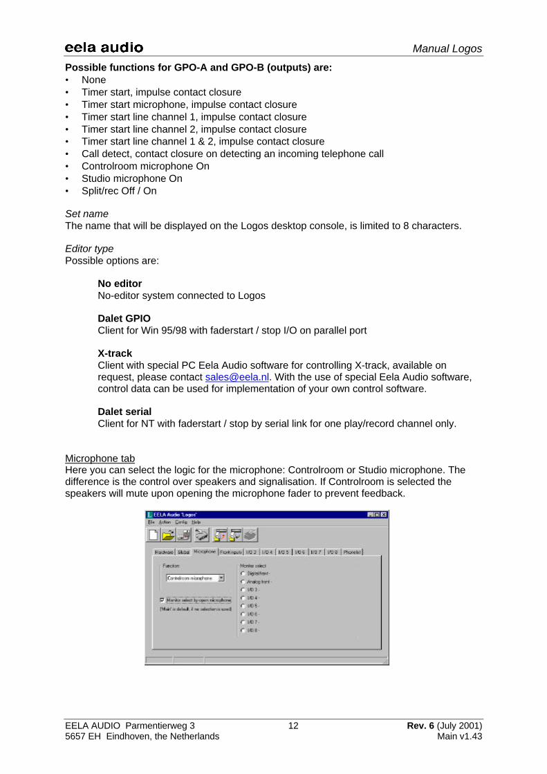
Global TabHere you can configure the function of the global GPIO and set the name and type of audioeditor used.
Moving the cursor over the GPIO functions will open a Windows balloon with the pinnumbers used of the GPIO connector. The back of the rackunit holds the 9 pole sub-Dconnector for the two GPI’s and the two GPO’s.
Possible functions for GPI-A and GPI-B (inputs) are:• None• Cough all• Cough microphone 1• Monitor muteRemark: engaging the cough function for a studio microphone will mute the microphoneinput, dim the monitor speakers and switch the studio microphone(s) to the monitor in orderto be able to talk to operator off-air. A blinking LED on the monitor button indicates thisfunction.
Manual Logos
EELA AUDIO Parmentierweg 3 12 Rev. 6 (July 2001)5657 EH Eindhoven, the Netherlands Main v1.43
Possible functions for GPO-A and GPO-B (outputs) are:• None• Timer start, impulse contact closure• Timer start microphone, impulse contact closure• Timer start line channel 1, impulse contact closure• Timer start line channel 2, impulse contact closure• Timer start line channel 1 & 2, impulse contact closure• Call detect, contact closure on detecting an incoming telephone call• Controlroom microphone On• Studio microphone On• Split/rec Off / On
Set nameThe name that will be displayed on the Logos desktop console, is limited to 8 characters.
Editor typePossible options are:
No editor No-editor system connected to Logos
Dalet GPIO Client for Win 95/98 with faderstart / stop I/O on parallel port
X-track Client with special PC Eela Audio software for controlling X-track, available onrequest, please contact [email protected]. With the use of special Eela Audio software,control data can be used for implementation of your own control software.
Dalet serial Client for NT with faderstart / stop by serial link for one play/record channel only.
Microphone tabHere you can select the logic for the microphone: Controlroom or Studio microphone. Thedifference is the control over speakers and signalisation. If Controlroom is selected thespeakers will mute upon opening the microphone fader to prevent feedback.
Manual Logos
EELA AUDIO Parmentierweg 3 13 Rev. 6 (July 2001)5657 EH Eindhoven, the Netherlands Main v1.43
By default the monitor will switch to main output upon opening the main microphone.Monitor select by open microphone allows you to select a different monitor source the unitwill switch to upon opening this fader. (Only available from Logos firmware version 1.40onwards). This selection can also be done through the microphone menu of the desktop unit,see Chapter 6).
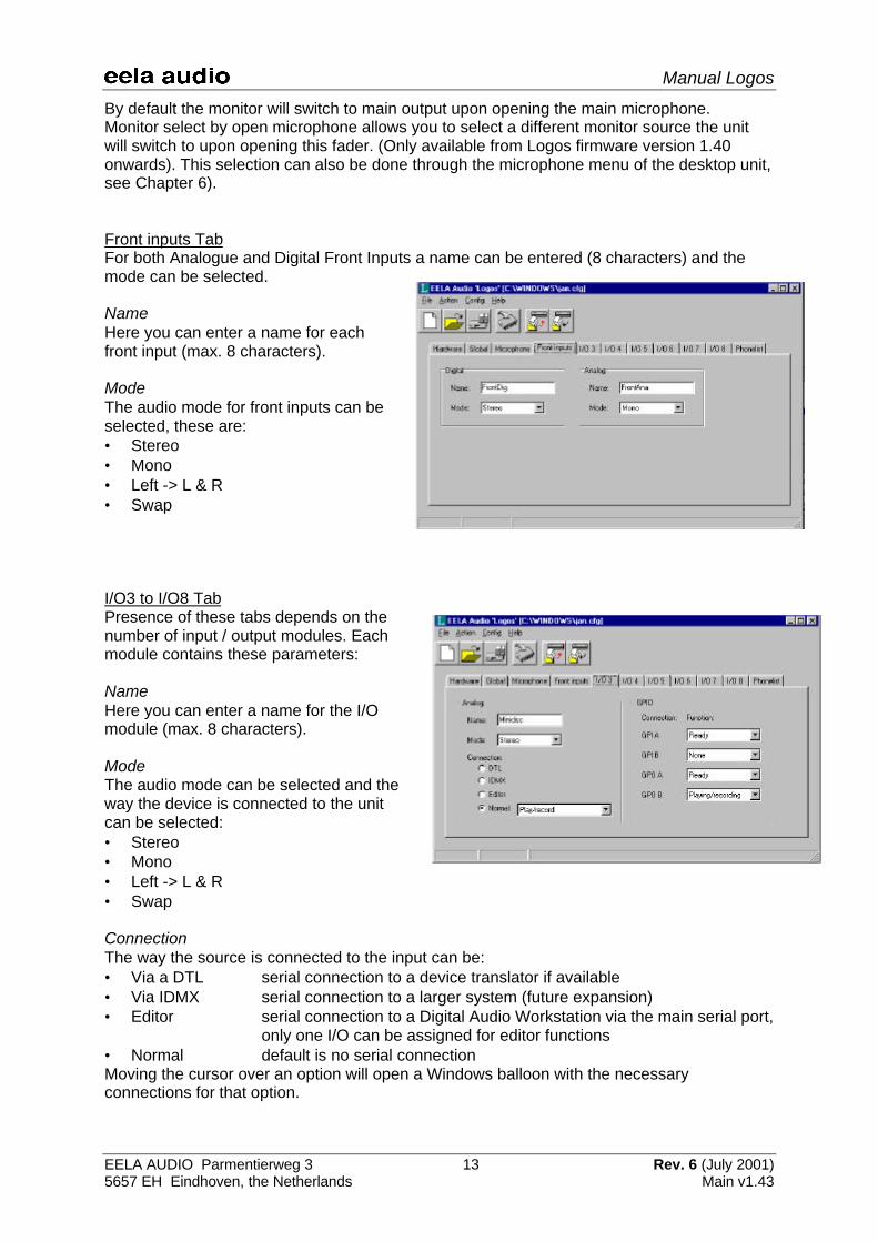
Front inputs TabFor both Analogue and Digital Front Inputs a name can be entered (8 characters) and themode can be selected.
NameHere you can enter a name for eachfront input (max. 8 characters).
ModeThe audio mode for front inputs can beselected, these are:• Stereo• Mono• Left -> L & R• Swap
I/O3 to I/O8 TabPresence of these tabs depends on thenumber of input / output modules. Eachmodule contains these parameters:
NameHere you can enter a name for the I/Omodule (max. 8 characters).
ModeThe audio mode can be selected and theway the device is connected to the unitcan be selected:• Stereo• Mono• Left -> L & R• Swap
ConnectionThe way the source is connected to the input can be:• Via a DTL serial connection to a device translator if available• Via IDMX serial connection to a larger system (future expansion)• Editor serial connection to a Digital Audio Workstation via the main serial port,
only one I/O can be assigned for editor functions• Normal default is no serial connectionMoving the cursor over an option will open a Windows balloon with the necessaryconnections for that option.

Manual Logos
EELA AUDIO Parmentierweg 3 14 Rev. 6 (July 2001)5657 EH Eindhoven, the Netherlands Main v1.43
If DTL (Device Translator) or IDMX is selected the GPIO’s functions are disabled. If thesource is an Editor you can select for both GP Inputs and Outputs:
GPI-A / GPO-B:• None• Ready, a tally signalling the device is ready
GPO-A / GPO-B:• None• Playing/Recording, continuous contact closure• Play/Rec Start, pulse on opening the fader• Play/Rec Stop, pulse on fader closure• Play/Rec Start/stop, pulse on fader opening and closing• Playing/Recording (low-active) continuous contact closure
If the 'Normal' device button is selected you need to specify a device.The options are:• None Output is Main• Controlroom microphone Output is Main• Studio microphone Output is Main• Play Only, no return signal Output is Main• Play/record Output is Main• Hybrid analogue, TB not active if fader open. Output is Cleanfeed• Codec/Hybrid digital, TB active if fader closed or open Output is Cleanfeed
GPI-A/B and GPO-A/B; these functions are device dependable:Microphone devices: a blinking LED on the PFL / monitor selector indicates an activeincoming cough on one of the external microphones. An active incoming coughfunction will mix all active microphones and route them to the monitor. The signal tothe main output is disabled.
GPI-A/B:• None• Cough / intercomGPO-A/B:• None• Microphone on
Play only devices:GPI-A/B:• None• Ready, a tally signalling the device is readyGPO-A/B:• None• Playing/Recording, continuous contact closure• Play/Rec Start, pulse on opening the fader• Play/Rec Stop, pulse on fader closure• Play/Rec Start/stop, pulse on fader opening and closing• Playing/Recording (low-active) continuous contact closure
Play/record devices:GPI-A/B:• None• Ready
Manual Logos
EELA AUDIO Parmentierweg 3 15 Rev. 6 (July 2001)5657 EH Eindhoven, the Netherlands Main v1.43
GPO-A/B:• None• Playing/Recording, continuous contact closure• Play/Rec Start, pulse on opening the fader• Play/Rec Stop, pulse on fader closure• Play/Rec Start/stop, pulse on fader opening and closing• Playing/Recording (low-active) continuous contact closure
Hybrid analogue devices:GPI-A/B:• None• Call, signalling an incoming call• Call/Ready, combined incoming call hybrid ready signal• Hybrid On, tally hybrid onGPO-A/B:• None• Online, contact closure switching hybrid on with <F1> function key• Hold, "fader switch" contact closure, signalling the hybrid "on-air".
Codec/Hybrid digital devices:GPI-A/B:• None• Call, tally signalling an incoming call• Call/Ready, combined incoming call and ready signal• Codec/Hybrid On, tally codec / hybrid onGPOA/B:• None• Online, contact closure switching hybrid on with <F1> function key• Hold, "fader switch" contact closure, signalling the hybrid "on-air".
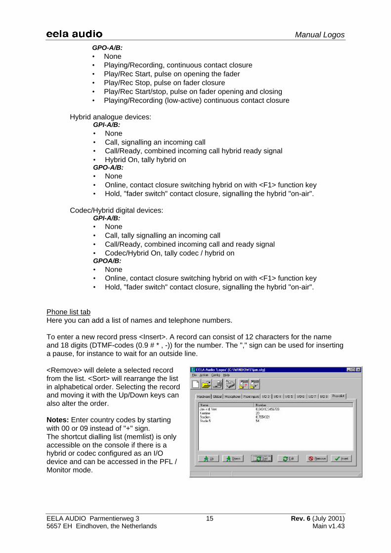
Phone list tabHere you can add a list of names and telephone numbers.
To enter a new record press <Insert>. A record can consist of 12 characters for the nameand 18 digits (DTMF-codes (0.9 # * , -)) for the number. The "," sign can be used for insertinga pause, for instance to wait for an outside line.
<Remove> will delete a selected recordfrom the list. <Sort> will rearrange the listin alphabetical order. Selecting the recordand moving it with the Up/Down keys canalso alter the order.
Notes: Enter country codes by startingwith 00 or 09 instead of "+" sign.The shortcut dialling list (memlist) is onlyaccessible on the console if there is ahybrid or codec configured as an I/Odevice and can be accessed in the PFL /Monitor mode.
Manual Logos
EELA AUDIO Parmentierweg 3 16 Rev. 6 (July 2001)5657 EH Eindhoven, the Netherlands Main v1.43
4 Start-up of the Logos
After turning on the power of the Logos, the initialising process will start and after a fewseconds the Logos will be ready for operation. Upon start-up the version number of theembedded software and the text "initialise" will be displayed in the LCD screen.
Upon start-up the left fader will have default the Digital Front input selected while the rightfader will have the Analogue Front input selected. The display will indicate the name EELAAUDIO LOGOS and the programmed user name.
The function Split/Record can be switched On or Off by pressing the <F1> key. Split/recordmeans that all line output signals will be routed to the right main output in mono and themicrophone 1 signal will be routed to the left output in mono.Future versions of the Logos will have the Split/Record function build into the LogosToolsoftware instead of the function present in the hardware.
Manual Logos
EELA AUDIO Parmentierweg 3 17 Rev. 6 (July 2001)5657 EH Eindhoven, the Netherlands Main v1.43
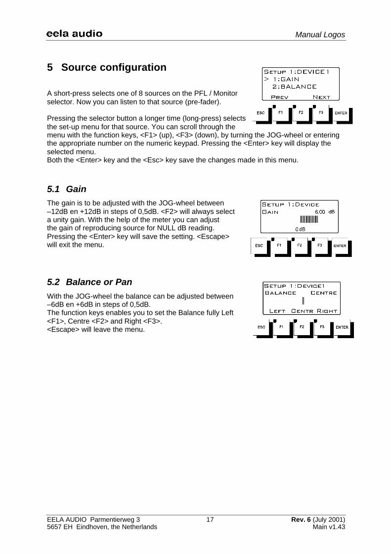
5 Source configuration
A short-press selects one of 8 sources on the PFL / Monitorselector. Now you can listen to that source (pre-fader).
Pressing the selector button a longer time (long-press) selectsthe set-up menu for that source. You can scroll through themenu with the function keys, <F1> (up), <F3> (down), by turning the JOG-wheel or enteringthe appropriate number on the numeric keypad. Pressing the <Enter> key will display theselected menu.Both the <Enter> key and the <Esc> key save the changes made in this menu.
5.1 GainThe gain is to be adjusted with the JOG-wheel between–12dB en +12dB in steps of 0,5dB. <F2> will always selecta unity gain. With the help of the meter you can adjustthe gain of reproducing source for NULL dB reading.Pressing the <Enter> key will save the setting. <Escape>will exit the menu.
5.2 Balance or PanWith the JOG-wheel the balance can be adjusted between–6dB en +6dB in steps of 0,5dB.The function keys enables you to set the Balance fully Left<F1>, Centre <F2> and Right <F3>.<Escape> will leave the menu.
Manual Logos
EELA AUDIO Parmentierweg 3 18 Rev. 6 (July 2001)5657 EH Eindhoven, the Netherlands Main v1.43
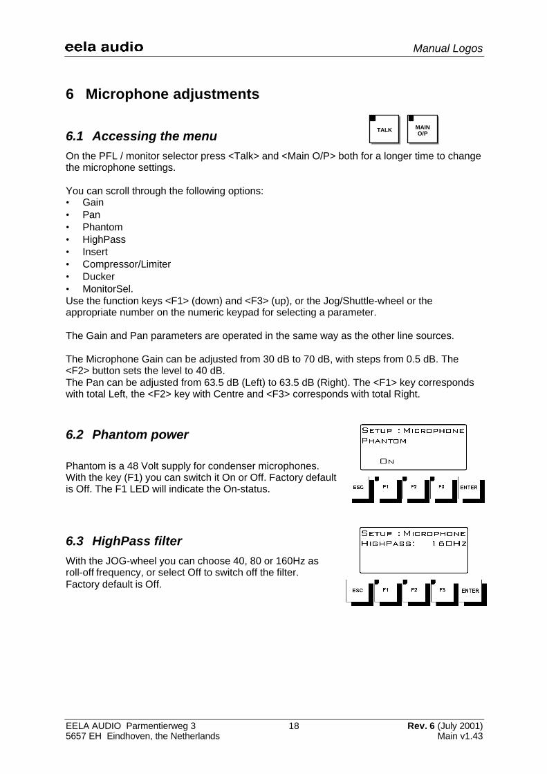
6 Microphone adjustments
6.1 Accessing the menuOn the PFL / monitor selector press <Talk> and <Main O/P> both for a longer time to changethe microphone settings.
You can scroll through the following options:• Gain• Pan• Phantom• HighPass• Insert• Compressor/Limiter• Ducker• MonitorSel.Use the function keys <F1> (down) and <F3> (up), or the Jog/Shuttle-wheel or theappropriate number on the numeric keypad for selecting a parameter.
The Gain and Pan parameters are operated in the same way as the other line sources.
The Microphone Gain can be adjusted from 30 dB to 70 dB, with steps from 0.5 dB. The<F2> button sets the level to 40 dB.The Pan can be adjusted from 63.5 dB (Left) to 63.5 dB (Right). The <F1> key correspondswith total Left, the <F2> key with Centre and <F3> corresponds with total Right.
6.2 Phantom power
Phantom is a 48 Volt supply for condenser microphones.With the key (F1) you can switch it On or Off. Factory defaultis Off. The F1 LED will indicate the On-status.
6.3 HighPass filterWith the JOG-wheel you can choose 40, 80 or 160Hz asroll-off frequency, or select Off to switch off the filter.Factory default is Off.
TALK MAINO/P
Manual Logos
EELA AUDIO Parmentierweg 3 19 Rev. 6 (July 2001)5657 EH Eindhoven, the Netherlands Main v1.43
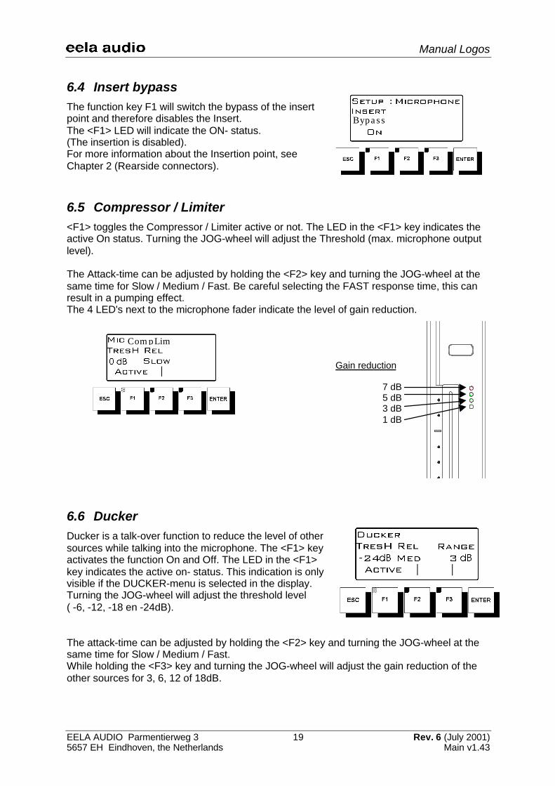
6.4 Insert bypassThe function key F1 will switch the bypass of the insertpoint and therefore disables the Insert.The <F1> LED will indicate the ON- status.(The insertion is disabled).For more information about the Insertion point, seeChapter 2 (Rearside connectors).
6.5 Compressor / Limiter<F1> toggles the Compressor / Limiter active or not. The LED in the <F1> key indicates theactive On status. Turning the JOG-wheel will adjust the Threshold (max. microphone outputlevel).
The Attack-time can be adjusted by holding the <F2> key and turning the JOG-wheel at thesame time for Slow / Medium / Fast. Be careful selecting the FAST response time, this canresult in a pumping effect.The 4 LED's next to the microphone fader indicate the level of gain reduction.
6.6 DuckerDucker is a talk-over function to reduce the level of othersources while talking into the microphone. The <F1> keyactivates the function On and Off. The LED in the <F1>key indicates the active on- status. This indication is onlyvisible if the DUCKER-menu is selected in the display.Turning the JOG-wheel will adjust the threshold level( -6, -12, -18 en -24dB).
The attack-time can be adjusted by holding the <F2> key and turning the JOG-wheel at thesame time for Slow / Medium / Fast.While holding the <F3> key and turning the JOG-wheel will adjust the gain reduction of theother sources for 3, 6, 12 of 18dB.
Gain reduction
7 dB5 dB3 dB1 dB
Bypass
CompLim
Manual Logos
EELA AUDIO Parmentierweg 3 20 Rev. 6 (July 2001)5657 EH Eindhoven, the Netherlands Main v1.43
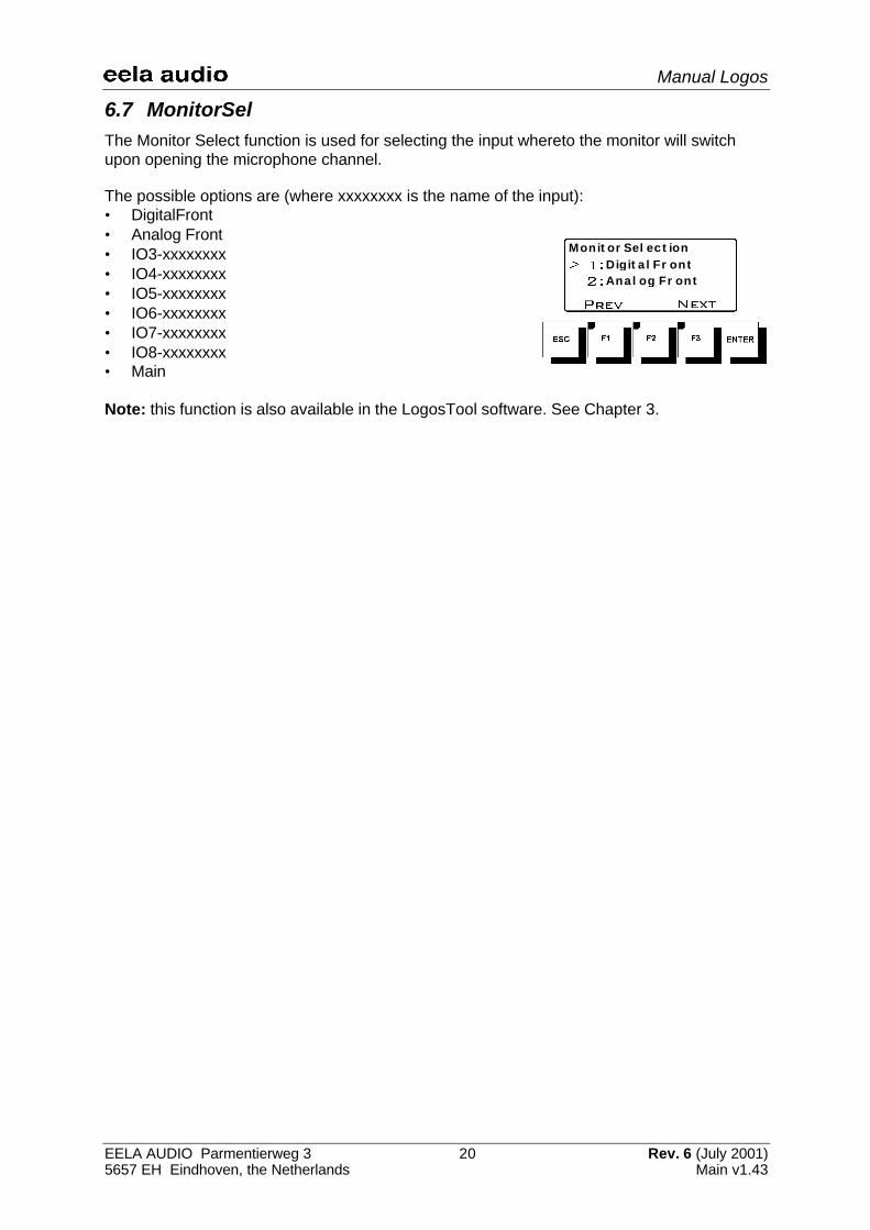
6.7 MonitorSelThe Monitor Select function is used for selecting the input whereto the monitor will switchupon opening the microphone channel.
The possible options are (where xxxxxxxx is the name of the input):• DigitalFront• Analog Front• IO3-xxxxxxxx• IO4-xxxxxxxx• IO5-xxxxxxxx• IO6-xxxxxxxx• IO7-xxxxxxxx• IO8-xxxxxxxx• Main
Note: this function is also available in the LogosTool software. See Chapter 3.
MonitorSelection
DigitalFrontAnalog Front

Manual Logos
EELA AUDIO Parmentierweg 3 21 Rev. 6 (July 2001)5657 EH Eindhoven, the Netherlands Main v1.43
Appendix 1: LOGOS Specifications
Power:
• Mains...................................................................................................................90-264VAC• Power consumption.................................................................................................. 22 Watt• Power supply fuse........................................................................................... F2,5A / 250V
Replacement types: Shurter SP0001.1008 or Littelfuse 21602.5
Connections:
• Main Output...................................................................................................... XLR 3p Male• Microphone Input.........................................................................................XLR 3p Female• Audio Inputs Digital/Analogue (Front) ........................................................XLR 3p Female• Audio Inputs Digital/Analogue 3-8 (Rear) .............................................25p Sub-D Female• Headphone ...............................................................................................................¼” Jack• Monitor ......................................................................................................................¼” Jack• Meter .........................................................................................................................¼” Jack• Mic Insert ..................................................................................................................¼” Jack• General Purpose I/O ................................................................................9p Sub-D Female• Host ...........................................................................................................9p Sub-D Female• Console....................................................................................................... Neutrik MiniCon• Mains............................................................................Neutrik PowerCon (Power-In, blue)
Audio Specifications:
• Bandwidth ..........................................................................................................20Hz-20kHz• Max. input level.........................................................................................................+20dBu• Max. output level.......................................................................................................+18dBu• Main output THD+Noise................................................< -86 dBu (LINE @ 6dBu at 1kHz)• Noise Main output (all faders closed)....................................................................< -86dBu• Signal to Noise Ratio (1 Line unity gain) ................................................................> 100dB• Interchannel crosstalk ............................................................................................> 100dB• Channel crosstalk ....................................................................... > 60dB (@100Hz-10kHz)• Input Channels
- MIC (Low gain 40dB) ...................................................................Balanced -34 dBu 2KΩ- MIC (High gain 60dB) ..................................................................Balanced -54 dBu 2KΩ- MIC Equ input noise......................................................................... < -127 dBu (@200Ω)- LINE........................................................................................... Balanced +6 dBu 20kΩ- Digital AES ................................................................................................... -9dBFS 110Ω
• Outputs- Main......................................................................................................... +6 dBu Balanced- Headphone ...........................................................................................................1W@8Ω- Monitor .................................................................................................+6dBu Unbalanced- Meter....................................................................................................+6dBu Unbalanced- (N-1) Analogue........................................................................................+6dBu balanced- (N-1) Digital / AES..................................................................................... -9dBFS@110Ω
Physical Specification:
Rackunit• Weight ..........................................................................................................................5,3 kg• Dimensions.........................................................................483 (W) x 88 (H) x 310 (D) mm
Console• Weight ..........................................................................................................................2,3 kg• Dimensions............................................................... 310 (W) x 245 (H) x 40 (D) mm MAX• Build-in dimensions............................................................304 (W) x 215 (H) x 35 (D) mm
Manual Logos
EELA AUDIO Parmentierweg 3 22 Rev. 6 (July 2001)5657 EH Eindhoven, the Netherlands Main v1.43
Appendix 2: Description sub-D25 and sub-D9 pinning
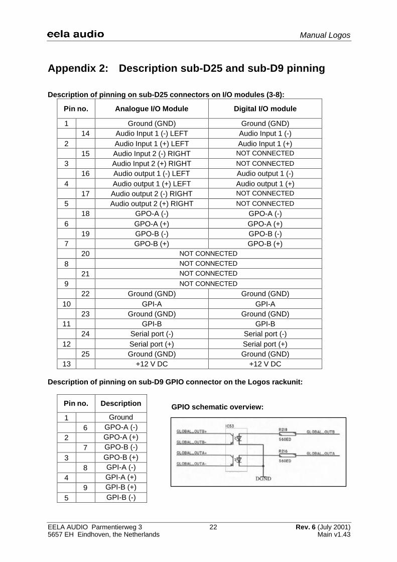
Description of pinning on sub-D25 connectors on I/O modules (3-8):
Pin no. Analogue I/O Module Digital I/O module
1 Ground (GND) Ground (GND)14 Audio Input 1 (-) LEFT Audio Input 1 (-)
2 Audio Input 1 (+) LEFT Audio Input 1 (+)15 Audio Input 2 (-) RIGHT NOT CONNECTED
3 Audio Input 2 (+) RIGHT NOT CONNECTED
16 Audio output 1 (-) LEFT Audio output 1 (-)4 Audio output 1 (+) LEFT Audio output 1 (+)
17 Audio output 2 (-) RIGHT NOT CONNECTED
5 Audio output 2 (+) RIGHT NOT CONNECTED
18 GPO-A (-) GPO-A (-)6 GPO-A (+) GPO-A (+)
19 GPO-B (-) GPO-B (-)7 GPO-B (+) GPO-B (+)
20 NOT CONNECTED
8 NOT CONNECTED
21 NOT CONNECTED
9 NOT CONNECTED
22 Ground (GND) Ground (GND)10 GPI-A GPI-A
23 Ground (GND) Ground (GND)11 GPI-B GPI-B
24 Serial port (-) Serial port (-)12 Serial port (+) Serial port (+)
25 Ground (GND) Ground (GND)13 +12 V DC +12 V DC
Description of pinning on sub-D9 GPIO connector on the Logos rackunit:
Pin no. Description
1 Ground6 GPO-A (-)
2 GPO-A (+)7 GPO-B (-)
3 GPO-B (+)8 GPI-A (-)
4 GPI-A (+)9 GPI-B (+)
5 GPI-B (-)
GPIO schematic overview:

Manual Logos
EELA AUDIO Parmentierweg 3 23 Rev. 6 (July 2001)5657 EH Eindhoven, the Netherlands Main v1.43
Appendix 3: UMC Hybrid connection (older version)
EA915x TELEPHONE HYBRID ßßàà LOGOS(version with sub-D9 connector)
sub-D9 Male EA915 sub-D25 Male Logos
1 ----------------- GND ---------------- 1
2 ----------------- Receive + ---------------- 26 ----------------- Receive - ---------------- 14
3 ----------------- Send + ----------------- 47 ----------------- Send - ----------------- 17
4 ----------------- Ext. On + ----------------- 68 ----------------- Ext. On - ----------------- 18
5 ----------------- Ring + ----------------- 109 ----------------- Ring - ----------------- 22
Screen should be connected to the housing, NOT to GND!!
Settings in LogosTool:
GPIA : Call/ReadyGPIB: NoneGPOA: On LineGPOB: None
EA-915 DIPSWITCH 1 to OFF !!!!!!!
Manual Logos
EELA AUDIO Parmentierweg 3 24 Rev. 6 (July 2001)5657 EH Eindhoven, the Netherlands Main v1.43
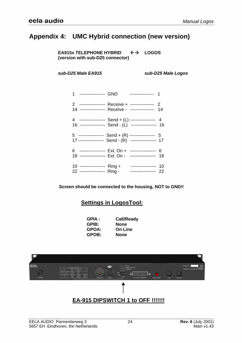
Appendix 4: UMC Hybrid connection (new version)
EA915x TELEPHONE HYBRID ßßàà LOGOS(version with sub-D25 connector)
sub-D25 Male EA915 sub-D25 Male Logos
1 ----------------- GND ---------------- 1
2 ----------------- Receive + ---------------- 214 ----------------- Receive - ---------------- 14
4 ----------------- Send + (L) ----------------- 416 ----------------- Send - (L) ----------------- 16
5 ----------------- Send + (R) ----------------- 517 ----------------- Send - (R) ----------------- 17
6 ----------------- Ext. On + ----------------- 618 ----------------- Ext. On - ----------------- 18
10 ----------------- Ring + ----------------- 1022 ----------------- Ring - ----------------- 22
Screen should be connected to the housing, NOT to GND!!
Settings in LogosTool:
GPIA : Call/ReadyGPIB: NoneGPOA: On LineGPOB: None
EA-915 DIPSWITCH 1 to OFF !!!!!!!

Manual Logos
EELA AUDIO Parmentierweg 3 25 Rev. 6 (July 2001)5657 EH Eindhoven, the Netherlands Main v1.43
Appendix 5: RS-232 cable Logos
RS-232 CONNECTOR FROM LOGOS TO PC:
Sub-D9 Female (PC) Sub-D9 Male (LOGOS)
1 1
2 ------------------- TX ---------------------- 26 6
3 ------------------- RX ---------------------- 37 7
4 48 8
5 ------------------- GND --------------------- 59 9
A FULLY WIRED PIN-TO-PIN CABLE IS ALSO OK!
Manual Logos
EELA AUDIO Parmentierweg 3 26 Rev. 6 (July 2001)5657 EH Eindhoven, the Netherlands Main v1.43
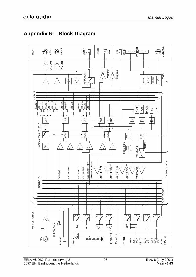
Appendix 6: Block Diagram3
21
312
312
321
321
321
OU
TPU
T-B
US
INP
UT-
BU
S
+48
VO
LT O
N/O
FF
CH
1-LE
FT
CH
1-R
IGH
T
CH
2-LE
FT
CH
2-R
IGH
T
MO
NIT
OR
-LE
FTM
ON
ITO
R-R
IGH
T
(N-1
) 1 L
EFT
(N-1
) 1 R
IGH
T
(N-1
) 2 L
EFT
(N-1
) 2 R
IGH
T
TALK
BA
CK
TALK
BA
CK D
TMF
300H
z-3K
hz
MO
NO
MO
NO
MO
NO
OFF
/40H
Z/80
HZ/
160H
Z
DC
A
DC
A
DC
A
DC
A
DC
A
INS
ER
T
MIC
HI/L
OW
GA
IN
FRO
NT
LEFT
RIG
HT
INP
UT
2
IN /
OU
T 3
- 8
I/O C
AR
D
GP
IO
MIX
-BU
SM
AIN
L(N
-1)1
L(N
-1)2
LM
AIN
R(N
-1)1
R(N
-1)2
RM
AIN
L
(N-1
)2L
MA
INR
(N-1
)2R
MA
INL
(N-1
)1L
MA
INR
(N-1
)1R
RA
M
RO
M
PR
GR
I/O
RA
M
RO
M
PR
GR
I/OU
P
386E
XC
ON
SO
LE
PC
-HO
ST
GP
IO
LSP
HP
H
FRO
NT
ME
TER
OU
T
MA
IN R
MA
IN L
RE
AR
INP
UT
1
DIG
IA
ES
PW
RA
MP
PW
RA
MPS
YM
OU
T
SY
MO
UT
MA
IN/M
ON
CO
NTR
OL-
BU
S
Manual Logos
EELA AUDIO Parmentierweg 3 27 Rev. 6 (July 2001)5657 EH Eindhoven, the Netherlands Main v1.43
Index
AES/EBU, 6; 7
Baud, 10
Cleanfeed, 7; 15Codec. Zie Hybrid.Condenser microphones, 7; 20Controlroom microphone, 3, 13; 15Cough, 9; 12; 15
Dalet, 5; 13Digigram X-track, 5
EA-915, 25; 26Earthed outlet, 9; 10Editor, 9; 13; 14; 15ESD, 9
Firmware, 10; 11; 14Fuse, 7; 23
GPIO, 9; 12; 13; 15; 24
Handshake, 10Hybrid, 1; 15; 16; 25; 26
Initialise, 18
Insertion point, 7
Loudspeaker, 9
Name, 10; 11; 12; 13; 14; 16; 18; 22Netia, 5
ON AIR bulb, 9Optocoupler, 9
Parity, 10Phantom, 1; 20Phone list, 16PPM, 4Printer, 11
Roll-off frequency, 20RS-232, 1; 27
Sample Rate Converter, 7SPDIF, 6; 7Studio microphone, 3; 13; 15
Telephone hybrid, 4; 7
XLR, 7X-track. Zie Digigram X-track
interstagePhistersvej 31, 2900 Hellerup, Danmark
Telefon 3946 0000, fax 3946 0040www.interstage.dk
- pro audio with a smile