manual - kem equipment operation specifics ... this module communicates to the engine ecu via the...
TRANSCRIPT
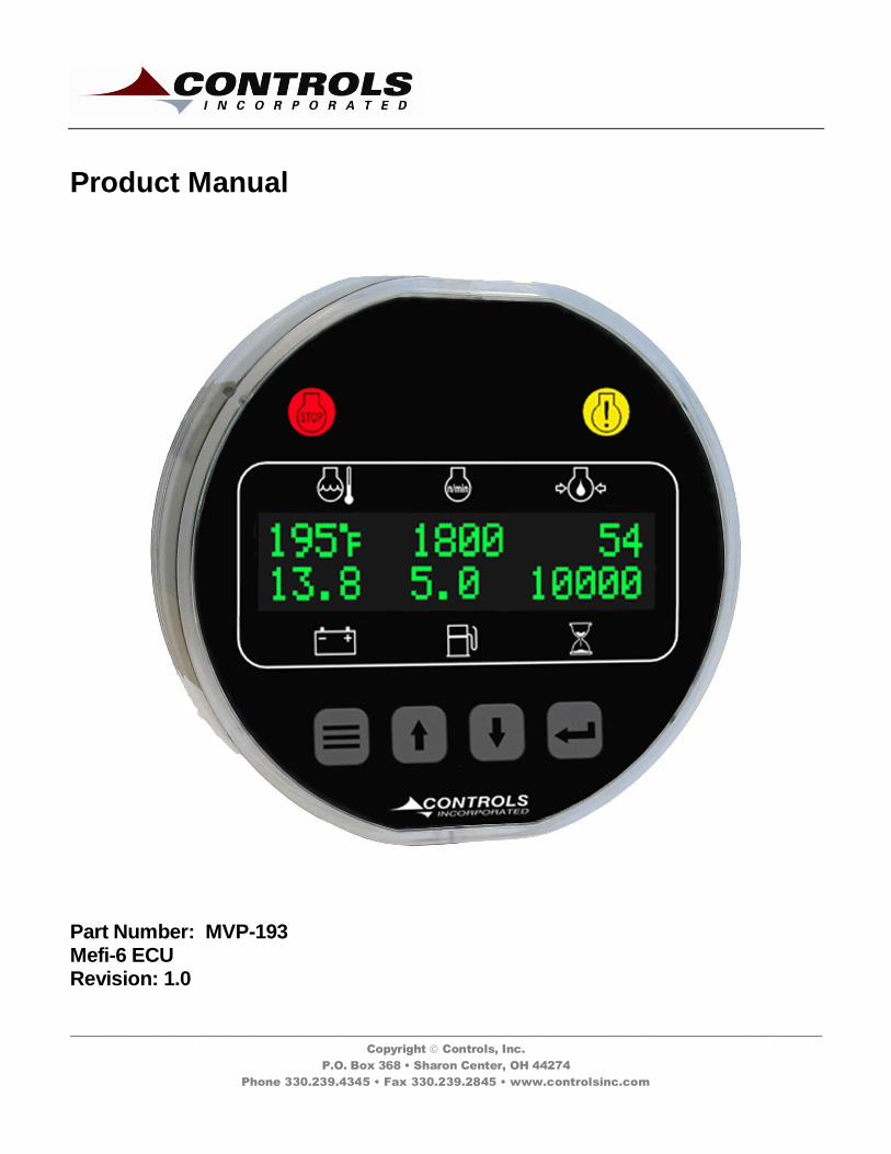
Product Manual
Part Number: MVP-193 Mefi-6 ECU Revision: 1.0
______________________________________________________________________________________________________________________________________
Copyright Controls, Inc.
P.O. Box 368 • Sharon Center, OH 44274
Phone 330.239.4345 • Fax 330.239.2845 • www.controlsinc.com
CONTROLS, INCORPORATED
C O N T R O L S Y S T E M S & S O L U T I O N S
- 1 -
TABLE OF CONTENTS
PRIOR TO ENGINE START………………...…………………………………………………………………….….…….……….…………...2
CAN Bus CONFIGURATION
THROTTLE SETTINGS…………………………..………………………………….……………………………………….….……………….....3
MANUAL OPERATION SPECIFICS
INSTALLATION INFORMATION……...........………………………………...……………………………………………………………....4
CONNECTOR INFORMATION……...........………………………………...………………………………………………………………….5
ENGINE ALARMS, CODES AND MESSAGES……………………………………………………………………………...……..6
ENGINE ECU ALARMS/DE-RATE/SHUT DOWNS ALARM ANNUNCIATION AND CODE READER PANEL INDICATION LAMPS ACTIVE AND STORED ENGINE ECU CODES
CONTROL PANEL ANALOG AND DIGITAL INPUTS……………………………………………………………………..…8
MENU SYSTEM……………………………………………………………………………………………..…………………………………….……10
MENU ACCESS, EXIT AND NAVIGATION MENUS TO VIEW INFORMATION MENUS TO CONFIGURE MODULE SETTINGS
CONTROLS, INCORPORATED
C O N T R O L S Y S T E M S & S O L U T I O N S
- 2 -
Prior to starting the engine, select the proper throttle control mode and parameters required for application.
CAN Bus Configuration
This module communicates to the engine ECU via the J1939 CAN Bus network. This is a three wire connection to the engine ECU. Engine information and alarm codes are broadcast over the CAN bus from the engine ECU to the controller display. And, the controller communicates throttle commands to the engine ECU over the CAN bus.
To assure proper communications between the engine ECU and the controller, the correct SOURCE ADDRESS and TSC1 ADDRESS need to be selected in the controller for the particular engine make and model. These settings are available in the CAN CONFIGURATION MENU.
CONTROLS, INCORPORATED
C O N T R O L S Y S T E M S & S O L U T I O N S
- 3 -
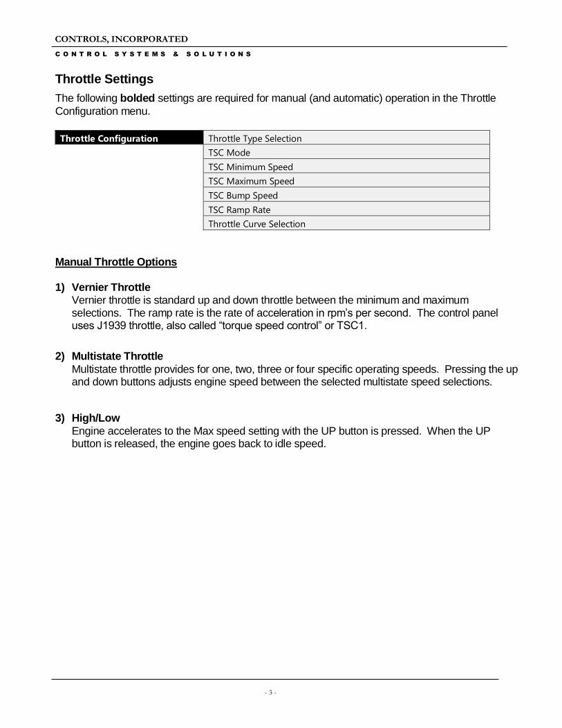
Throttle Settings
The following bolded settings are required for manual (and automatic) operation in the Throttle
Configuration menu.
Throttle Configuration Throttle Type Selection
TSC Mode
TSC Minimum Speed
TSC Maximum Speed
TSC Bump Speed
TSC Ramp Rate
Throttle Curve Selection
Manual Throttle Options 1) Vernier Throttle
Vernier throttle is standard up and down throttle between the minimum and maximum selections. The ramp rate is the rate of acceleration in rpm’s per second. The control panel uses J1939 throttle, also called “torque speed control” or TSC1.
2) Multistate Throttle
Multistate throttle provides for one, two, three or four specific operating speeds. Pressing the up and down buttons adjusts engine speed between the selected multistate speed selections.
3) High/Low
Engine accelerates to the Max speed setting with the UP button is pressed. When the UP button is released, the engine goes back to idle speed.
CONTROLS, INCORPORATED
C O N T R O L S Y S T E M S & S O L U T I O N S
- 4 -
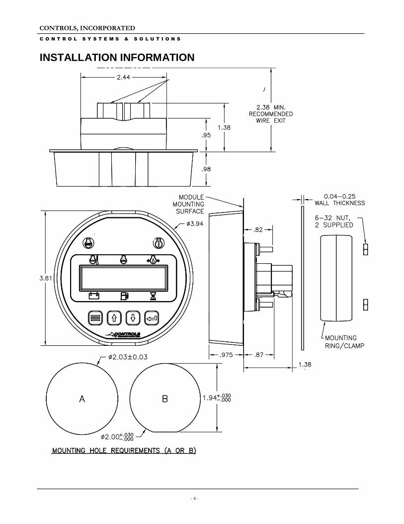
INSTALLATION INFORMATION
CONTROLS, INCORPORATED
C O N T R O L S Y S T E M S & S O L U T I O N S
- 5 -
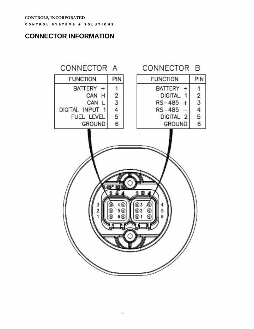
CONNECTOR INFORMATION
CONTROLS, INCORPORATED
C O N T R O L S Y S T E M S & S O L U T I O N S
- 6 -
ENGINE ALARMS, CODES AND MESSAGES
Engine ECU Alarm/De-Rate/Shut Downs It is important to understand panel operation with respect to engine safety protections, alarms, and fault codes. The panel operates with J1939 engines. These engines have an ECU (engine control unit) which is essentially a computer that runs the engine. When engine parameters are out of normal operating ranges, the ECU takes specific actions which can include the following:
1) Broadcast a trouble code
2) Broadcast a red or yellow lamp
3) De-rate the engine
4) Shut down the engine
5) Turn on alarm horn
It is the engine ECU that de-rates or shuts down the engine when it is not operating within normal parameters. This includes more common shut downs like high engine temperature and low oil pressure but can encompass a large range of parameters depending on the ECU.
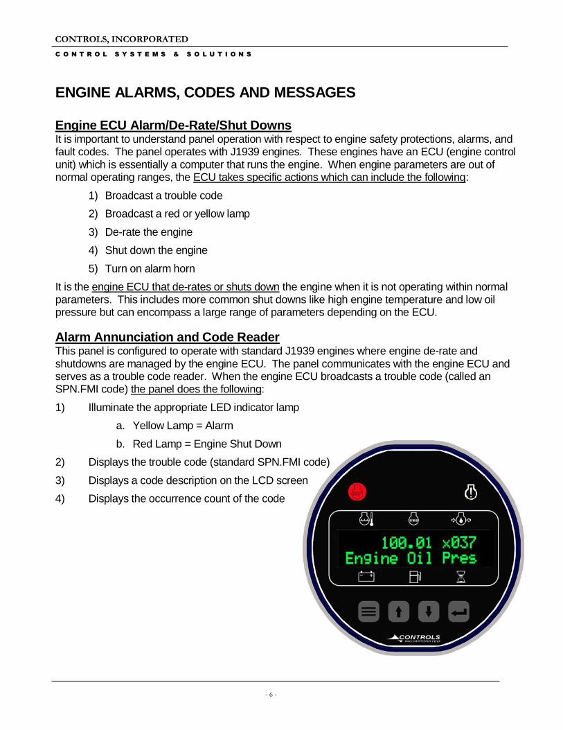
Alarm Annunciation and Code Reader This panel is configured to operate with standard J1939 engines where engine de-rate and shutdowns are managed by the engine ECU. The panel communicates with the engine ECU and serves as a trouble code reader. When the engine ECU broadcasts a trouble code (called an SPN.FMI code) the panel does the following:
1) Illuminate the appropriate LED indicator lamp
a. Yellow Lamp = Alarm
b. Red Lamp = Engine Shut Down
2) Displays the trouble code (standard SPN.FMI code)
3) Displays a code description on the LCD screen
4) Displays the occurrence count of the code
CONTROLS, INCORPORATED
C O N T R O L S Y S T E M S & S O L U T I O N S
- 7 -
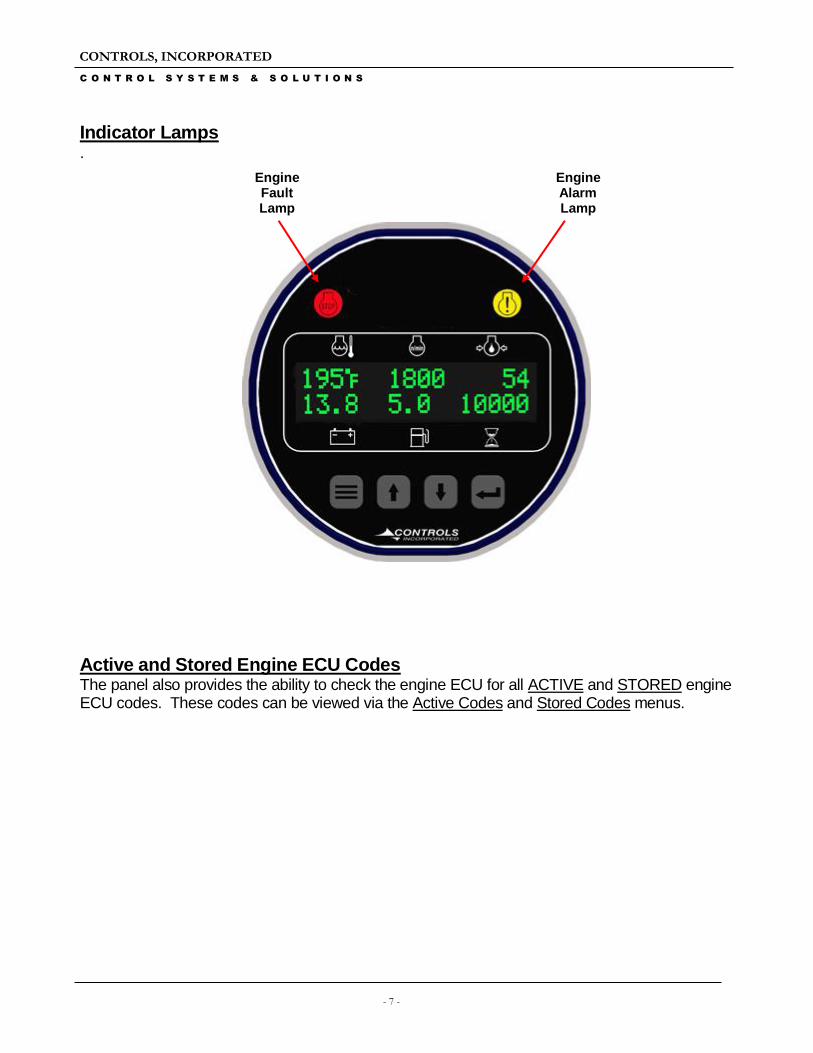
Indicator Lamps .
Active and Stored Engine ECU Codes The panel also provides the ability to check the engine ECU for all ACTIVE and STORED engine ECU codes. These codes can be viewed via the Active Codes and Stored Codes menus.
Engine Fault Lamp
Engine Alarm Lamp
CONTROLS, INCORPORATED
C O N T R O L S Y S T E M S & S O L U T I O N S
- 8 -
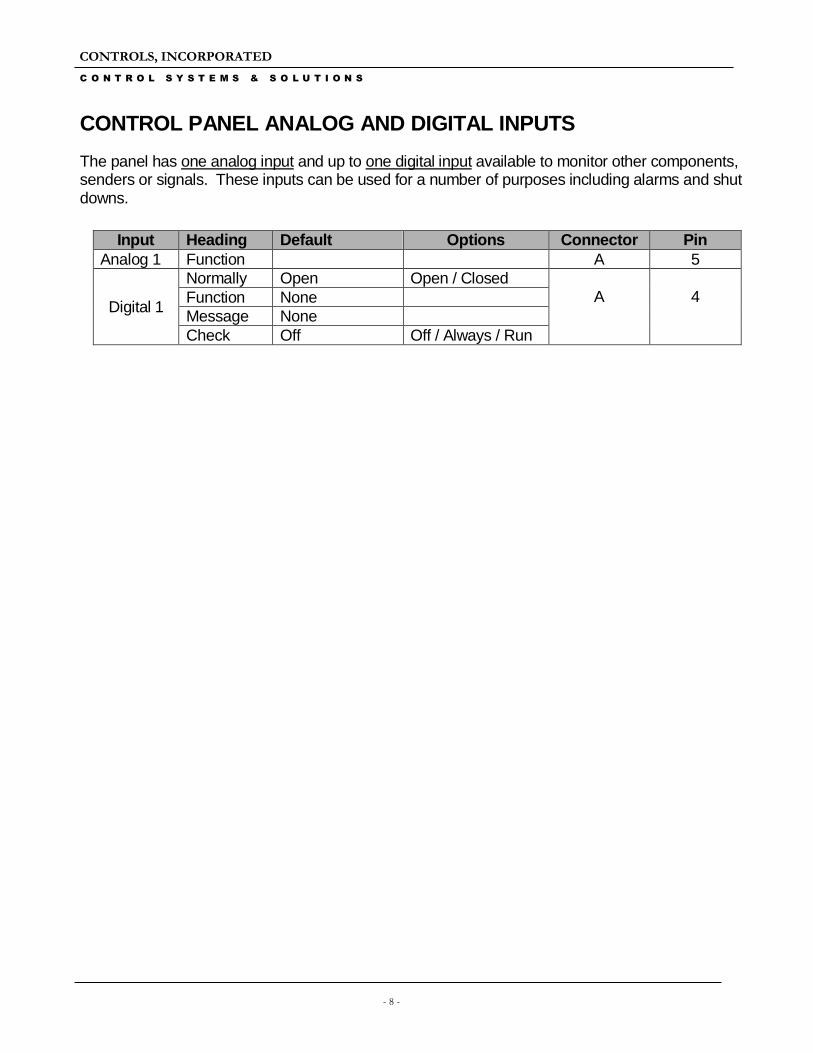
CONTROL PANEL ANALOG AND DIGITAL INPUTS
The panel has one analog input and up to one digital input available to monitor other components, senders or signals. These inputs can be used for a number of purposes including alarms and shut downs.
Input Heading Default Options Connector Pin
Analog 1 Function A 5
Digital 1
Normally Open Open / Closed A
4 Function None
Message None
Check Off Off / Always / Run
CONTROLS, INCORPORATED
C O N T R O L S Y S T E M S & S O L U T I O N S
- 9 -
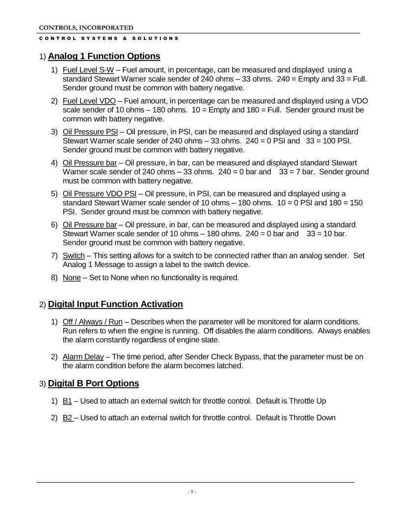
1) Analog 1 Function Options
1) Fuel Level S-W – Fuel amount, in percentage, can be measured and displayed using a standard Stewart Warner scale sender of 240 ohms – 33 ohms. 240 = Empty and 33 = Full. Sender ground must be common with battery negative.
2) Fuel Level VDO – Fuel amount, in percentage can be measured and displayed using a VDO scale sender of 10 ohms – 180 ohms. 10 = Empty and 180 = Full. Sender ground must be common with battery negative.
3) Oil Pressure PSI – Oil pressure, in PSI, can be measured and displayed using a standard Stewart Warner scale sender of 240 ohms – 33 ohms. 240 = 0 PSI and 33 = 100 PSI. Sender ground must be common with battery negative.
4) Oil Pressure bar – Oil pressure, in bar, can be measured and displayed standard Stewart Warner scale sender of 240 ohms – 33 ohms. 240 = 0 bar and 33 = 7 bar. Sender ground must be common with battery negative.
5) Oil Pressure VDO PSI – Oil pressure, in PSI, can be measured and displayed using a standard Stewart Warner scale sender of 10 ohms – 180 ohms. 10 = 0 PSI and 180 = 150 PSI. Sender ground must be common with battery negative.
6) Oil Pressure bar – Oil pressure, in bar, can be measured and displayed using a standard Stewart Warner scale sender of 10 ohms – 180 ohms. 240 = 0 bar and 33 = 10 bar. Sender ground must be common with battery negative.
7) Switch – This setting allows for a switch to be connected rather than an analog sender. Set Analog 1 Message to assign a label to the switch device.
8) None – Set to None when no functionality is required.
2) Digital Input Function Activation
1) Off / Always / Run – Describes when the parameter will be monitored for alarm conditions. Run refers to when the engine is running. Off disables the alarm conditions. Always enables the alarm constantly regardless of engine state.
2) Alarm Delay – The time period, after Sender Check Bypass, that the parameter must be on the alarm condition before the alarm becomes latched.
3) Digital B Port Options
1) B1 – Used to attach an external switch for throttle control. Default is Throttle Up
2) B2 – Used to attach an external switch for throttle control. Default is Throttle Down
CONTROLS, INCORPORATED
C O N T R O L S Y S T E M S & S O L U T I O N S
- 10 -
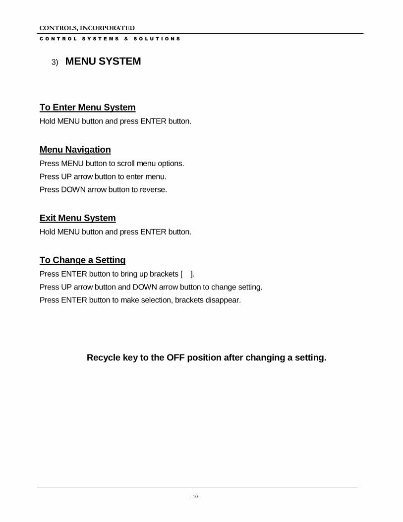
3) MENU SYSTEM
To Enter Menu System
Hold MENU button and press ENTER button.
Menu Navigation
Press MENU button to scroll menu options.
Press UP arrow button to enter menu.
Press DOWN arrow button to reverse.
Exit Menu System
Hold MENU button and press ENTER button.
To Change a Setting
Press ENTER button to bring up brackets [ ].
Press UP arrow button and DOWN arrow button to change setting.
Press ENTER button to make selection, brackets disappear.
Recycle key to the OFF position after changing a setting.
CONTROLS, INCORPORATED
C O N T R O L S Y S T E M S & S O L U T I O N S
- 11 -
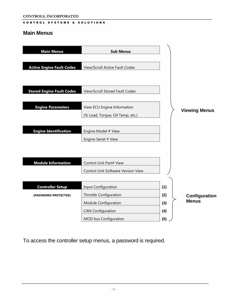
Main Menus
Main Menus Sub Menus
Active Engine Fault Codes View/Scroll Active Fault Codes
Stored Engine Fault Codes View/Scroll Stored Fault Codes
Engine Parameters View ECU Engine Information
(% Load, Torque, Oil Temp, etc.)
Engine Identification Engine Model # View
Engine Serial # View
Module Information Control Unit Part# View
Control Unit Software Version View
Controller Setup Input Configuration (1)
(PASSWORD PROTECTED) Throttle Configuration (2)
Module Configuration (3)
CAN Configuration (4)
MOD bus Configuration (5)
To access the controller setup menus, a password is required.
Viewing Menus
Configuration Menus
CONTROLS, INCORPORATED
C O N T R O L S Y S T E M S & S O L U T I O N S
- 12 -
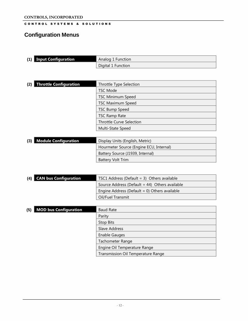
Configuration Menus
(1) Input Configuration Analog 1 Function
Digital 1 Function
(2) Throttle Configuration Throttle Type Selection
TSC Mode
TSC Minimum Speed
TSC Maximum Speed
TSC Bump Speed
TSC Ramp Rate
Throttle Curve Selection
Multi-State Speed
(3) Module Configuration Display Units (English, Metric)
Hourmeter Source (Engine ECU, Internal)
Battery Source (J1939, Internal)
Battery Volt Trim
(4) CAN bus Configuration TSC1 Address (Default = 3) Others available
Source Address (Default = 44) Others available
Engine Address (Default = 0) Others available
Oil/Fuel Transmit
(5) MOD bus Configuration Baud Rate
Parity
Stop Bits
Slave Address
Enable Gauges
Tachometer Range
Engine Oil Temperature Range
Transmission Oil Temperature Range