manual generador engga
DESCRIPTION
Manual Generador ENGGATRANSCRIPT

ENGGA Three-phase Synchronous Generators
Operation And Maintenance Manual
1
General Safety Warning
EG Series generators are manufactured and incorporated with the latest design technology which enhances the
production process and strict quality control. Together with ENGGA patented technology on the Main Rotor and
Main Stator assembly have uplifted the product total reliability, quantity and superiority as a whole.
This manual contains information that is only suitable for use by qualified engineers and it is strongly recommended
that the User must read and fully understand this Operation and Maintenance Manual thoroughly. All subject related
to safety regulation and laws, technical standard, transportation method, installation, operation, maintenance and
repaired must be fully observed. The machines have dangerous part and when running, they have live and rotating
components. It must have adequate inspection and maintenance by qualified engineers to ensure no personal injury
or property damage.
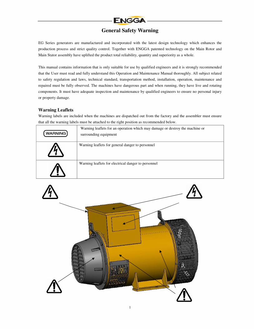
Warning Leaflets
Warning labels are included when the machines are dispatched out from the factory and the assembler must ensure
that all the warning labels must be attached to the right position as recommended below.
Warning leaflets for an operation which may damage or destroy the machine or
surrounding equipment
Warning leaflets for general danger to personnel
Warning leaflets for electrical danger to personnel
2
INDEX
1 INTRODUCTION
1.1 Standard
1.2 Name-plate description
1.3 Name-plate
1.4 Delivery inspection and storage
2 GENERATOR APPLICATION
2.1 Application
2.2 De-Rating table
3 GENERATOR PRINCIPLE
3.1 Operating principle
3.2 Main Stator
3.3 Main Rotor
3.4 Exciter
3.5 Automatic Voltage Regulator
4 INSTALLATION
4.1 Operating conditions
4.2 Installation
4.3 Rotation
4.4 Electrical connection
4.5 Protection
5 STARTING UP
5.1 Check before staring up
5.2 Commissioning
6 MAINTENANCE
6.1 General maintenance
6.2 Inspection and maintenance
6.3 Troubleshooting
6.4 AVR checking
7 STRUCTURAL DRAWING
8 PARTS LIST

3
All the generator ratings are specified in the name-plate and if any abuses or not operating
according to the ratings conditions, the manufacturer shall not be held responsible should any damage occurred.
1 INTRODUCTION
1.1 Standard
ENGGA generators are designed in compliance to I.E.C 60034-1; BS 4999-5000; NEMA MG 1.22; C.S.A C22-2; VDE
0530 and GB755 standard; ISO9001:2000 certified and CE Marking and CCS approved.
1.2 Name-plate description
Example: EG280S—120N
EG - EG series generator 280 -Generator frame size (160; 225; 280; 315; 355; 400; 500)
S - Core length (M; L) 120 - Generator output in kW
N - designation of different version (N- latest 2007 series;H – marine application;B – non standard machines)
1.3 Name-plate
Name-plates are of special sticker type and shall be stick onto the right hand side of the generator drive end position.
1.4 Delivery inspection and storage
Customer shall open the wooden case immediately to check the generator’s name-plate, other documents and thoroughly
inspect all the machines to make sure everything is in proper order or any visible damaged to the machine after receiving it.
After that, if the generator is not to be installed at once, please pack it again and properly stored it in a dry and damp proof
place. The manufacturer shall not be held responsible for any damages which results from improper storage.
2 GENERATOR APPLICATION
2.1 Application
EG series generator rated output shall be installed and operated according to the following altitude and temperature.
a. Altitude height shall not over 1000m.a.s.l ;
b. Environment temperature shall be between -40ºC and 40 ºC respectively ;
c. Cool air relative humidity: ≤95%(25 ºC );
d. Generator shall be operated in a protected area and shall not be directly exposed to rain.
2.2 De-Rating table
Following de-rating table must be considered if the generator is operated in under below conditions
Altitude (m.a.s.l) Revise coefficient Temperature( ºC ) Revise coefficient
1500 0.96 45 0.96
2000 0.93 50 0.93
2500 0.90 55 0.90
3000 0.87 60 0.88
3500 0.85
4000 0.82
If generator application altitude and temperature are both above the standard, revise coefficient shall be calculated together.

4
3 GENERATOR PRINCIPLE
3.1 Operation Principle
When the rotor being driven by the prime mover, a small magnetic field was set up and due to this, a small voltage is
induced. The AVR will sense this low voltage and compare it with the required voltage level. The AVR will find initially the
sensed voltage is considerably low than the required voltage. The AVR will provide such power from the main stator
winding to establish the exciter field. The exciter also have a small amount of residual magnetism.
The power from the main output winding (rectified by going through the AVR) will add to this residual level to produce a
greater magnetic field strength. With the exciter magnetic field strength increased, the a.c. output voltage from the exciter
rotor will also increase. This voltage is rectified by the rotating diodes. This extra excitation adds to the residual level of the
main field and produces an increase in output voltage from the main stator.
The AVR senses this increase and will further increase the excitation field excitation. The main stator voltage is building up
until the sensed voltage is the same as the required voltage.
Fig. 1 Operation Principle
A change in output due to load current is automatically compensated for by the AVR. This will adjust the excitation under all
circumstances in order to achieve minimum error between the sensed output voltage and the required voltage.
3.2 Main stator
The main stator frames are most ruggedly constructed with high strength and solid support. The frame is welded with heavy
rings and steel bars and reinforced with welding plates between bars. The main stator windings are the configuration of
triple-layer winding insulation type to ensure maximum insulation properties. All laminations of the stator core are
externally welded under pressure, to obtain the iron core. Ventilation ducts are provided along the stator core.
3.3 Main rotor
The main rotor is also the configuration of triple-layer winding protection type and the copper wires are of special made
rectangular type. The magnetic core of the main field is directly mounted on the shaft. The laminated rotor core reduces the
effect of superficial losses on the rotor. The rotor core at both end is incorporated with additional copper laminations and are
used as “end rings” for the copper squirrel cage. The rotor is then completed with the ammortisseur winding: it is composed
by several bare copper rods directly passing through the holes next to the surfaces of the poles. The rods are welded at both
ends to the additional copper laminations.

5
3.4 Exciter
The exciter is considered as a small synchronous generator and its being installed at the non-drive end of the generator. All
the electrical power output produced by the exciter is rectify and used to establish the magnetic field of the main machine.
3.5 Automatic Voltage Regulator
The WT-2 Voltage Regulator is an encapsulated unit contained in a plastic case. The regulator controls the dc
exciter field power of conventional, 50 or 60 Hz brushless generators that have a max 63 Vdc exciter field to
regulate the generator output voltage. Regulation is provided by sensing the generator output voltage,
converting it to a dc signal and comparing the signal to a reference voltage signal. An error signal is developed
and used to control the dc field power in order to maintain a constant generator output.
Fig. 2 Connection of WT-2 in 200VAC system

6
Fig. 3 Connection of WT-2 in 400VAC system
CONNECTION OF AVR
- the “J” is a connection for 50 Hz operation, or disconnection the “J” for 60 Hz operation.
- If an external voltage adjust control is being used, connect the potentiometer (minimum 1W, resistance
2000 Ω) to terminals Rv1 and Rv2. If not, connect a jumper between terminals Rv1 and Rv2.
- Connect the exciter field to terminals F+ and F-. Be sure to observe polarity.
- Connect the input power to the generator stator to provide power to terminals P1 and P4. The input should
be connected 200~277Vac.
- Connect the sensing input P2 and P4 for 400Vac operation or P3 and P4 for 200 Vac operation. The sensing
should be connected "line to line ".
PARALLEL OPERATION
When it is required to operate the regulator in parallel with an isolated or utility bus, in addition to the regulator
provisions, a 5 VA current transformer (CT) is required (See Figures 2 and 3.) This CT is connected in a generator
U line and should deliver from TP1 to TP2 amperes secondary current at rated load. The phase relationship of CT
signal to the regulator sensing voltage must be correct or the system will not parallel properly. The CT must be
installed in the U line of the three-phase generator. That does not supply sensing to the regulator.
Figures 2 and 3 show the correct CT polarity for A-B-C phase rotation sequence. If the phase rotation sequence is
A-C-B, the CT’s secondary leads must be interchanged.
ADJUSTMENTS
VOLT - potentiometer for adjusting the output voltage of the generator: to adjust the output voltage of the
generator: the voltage adjustment possibility depends on the characteristics of the generator. Normally the
internal potentiometer RP1 allows possibility of adjusting the voltage in a wide range (i.e. between 350 and 480 V,
or between 170 and 277 V); to obtain setting or to adjust the voltage from the control panel, or in order to limit
the voltage range, an external potentiometer can connected a finer possibility of voltage to the terminal “RV1”
and “RV2” (resistance about 2000 Ohm, 1W, to obtain +/- 5% voltage regulation).
⇒⇒⇒⇒ increase voltage
FREQ -potentiometer for changing the low speed protection: usually it is set at the factory in order to reduce the excitation when speed becomes lower than 90% of rated speed at 50 Hz. By removing the bridge which normally
shorts the terminals “Hz” and “60”, the speed protection acts properly for 60 Hz operation. By acting on
potentiometer RP3 it is possible to adjust further (in case should it be necessary) the frequency at which the low
speed protection is effective.
⇒⇒⇒⇒decrease frequency of intervention
STABILITY SETTING - The voltage regulator is provided with internal adjustable stability circuits in order to
allow operation in a wide range of applications. The operation of the regulator can be set on field to adapt it to
the characteristics of the plant and of the driving engine (i.e. diesel engine, water turbine, gas turbine) in order to
obtain the best voltage response. To change the stability characteristics of the regulator, it is necessary to act on
the potentiometer “RP2” for fine setting of stability
⇒⇒⇒⇒ increase response time, increase stability
7
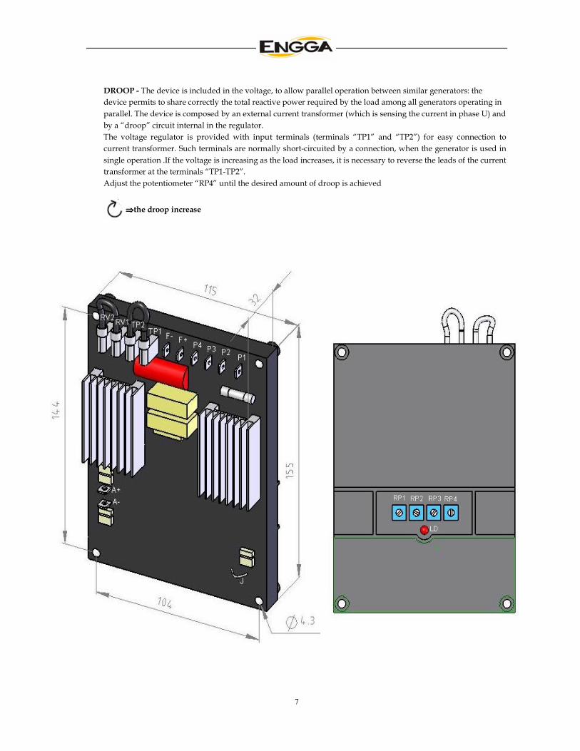
DROOP - The device is included in the voltage, to allow parallel operation between similar generators: the
device permits to share correctly the total reactive power required by the load among all generators operating in
parallel. The device is composed by an external current transformer (which is sensing the current in phase U) and
by a “droop” circuit internal in the regulator.
The voltage regulator is provided with input terminals (terminals “TP1” and “TP2”) for easy connection to
current transformer. Such terminals are normally short-circuited by a connection, when the generator is used in
single operation .If the voltage is increasing as the load increases, it is necessary to reverse the leads of the current
transformer at the terminals “TP1-TP2”.
Adjust the potentiometer “RP4” until the desired amount of droop is achieved
⇒⇒⇒⇒the droop increase
8
During assembling of the generator, it is a must to ensure the machine is properly aligned.
Proper installation of the generator is of paramount importance to ensure a long lifespan of the
machine and shall be installed or assembled by highly qualified personnel only.
4 INSTALLATION
4.1 Operation Conditions
First of all, the operation conditions of the generator shall be identified before installation. The generator shall be operated
and installed in a clean environment, with good air flow and with ample of space for inspection, maintenance and routine
checking. The surrounding of the generator shall be free of atmospheric contaminations such as gasses and various
chemicals, salt water spray, dust and rainfall. It is also important to have a good airflow position, away from any hot or
exhaust system.
It is also recommended that if the generator were to install in an area with high condensation, a space heater shall be added
as an extra protection. If installed in an area of heavy laden of fine dust or sand, an inlet air filter shall be added on but due to
these, a certain output duration is required.
4.2 Installation
During assembling of the generator and the engine, it is important to have a solid and rigid base-frame to ensure no frame
deformation or frame twisting arises. We recommended to use Grade 8.8 bolt and nuts to assemble the generator set and to
also make sure the base-frame is sitting firmly to the ground surface. During installation, it is also important not to harm the
bearing and shall always keep the rotor assembly in alignment.
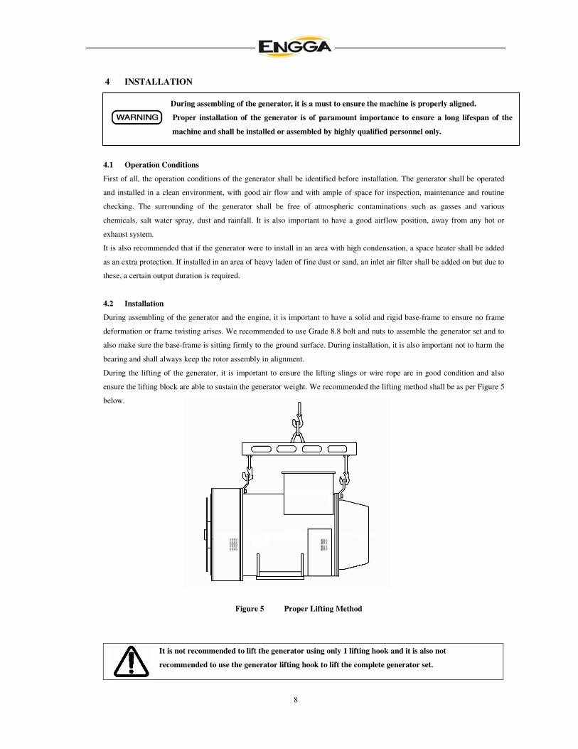
During the lifting of the generator, it is important to ensure the lifting slings or wire rope are in good condition and also
ensure the lifting block are able to sustain the generator weight. We recommended the lifting method shall be as per Figure 5
below.
Figure 5 Proper Lifting Method
It is not recommended to lift the generator using only 1 lifting hook and it is also not
recommended to use the generator lifting hook to lift the complete generator set.
9
To ensure a proper generator set installation, it is important to have both the generator and the engine is properly alignment.
For both single or double bearing configuration generator, there is a SAE standard for the flange/adaptor and coupling disc
which is suitable for assembly with of Generator-Drive engine brands. Should the needs arise to use other non standard SAE
housing size, please kindly contact the manufacturer to confirm.
If the alignment of the generator to the engine is not in proper order, this could results in severe
personal injury, property damage or direct damage to the machine.
4.2.1 Single bearing generator installation
Assembling procedure are as follow :-
- initial checking of the engine housing and flywheel measurement is correct as per generator flange and coupling SAE
dimension supplied.
- dismantle the flange cover, position the generator in-line with the engine and then aligned the generator flange to the
engine housing. After that, align the generator coupling to the engine flywheel. This is to make sure all the surface is
vertically in-line with each other. Should it is not align, it can be adjusted by adding several shim to the baseframe.
- bolt the coupling disc to the flywheel housing using recommended number of bolts and size. We recommended to use
Grade 8.8 or above bolt type.
- it is recommended to turn the rotor to check there is no touching between the rotor and the stator assembly.
- after assembling the generator footing to the baseframe, the install back the flange cover.
4.2.2 Double bearing generator installation
Assembling procedure are as follow :-
- standard generators supplied are without special housing for connection between the generator to the engine housing
and can be available upon request..
- before installation, it is required to have a pre-balancing coupling/adaptor fit to the generator shaft end.
- position the generator in-line with the engine and then aligned the generator to the engine side. After that, align the
generator pre-balanced coupling to the engine flywheel. This is to make sure all the surface is vertically in-line with
each other.
- Should it is not align, it can be adjusted by adding several shim to the baseframe.
- it is recommended to turn the rotor to check there is no touching between the rotor and the stator assembly.
- after that, assemble the generator footing to the baseframe.
4.3 Rotation
Please ensure the generator rotating direction shall be the same as the label indicated direction. Generators are normally
supplied to operate correctly when rotating clockwise.
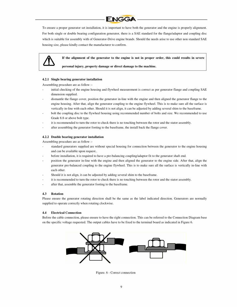
4.4 Electrical Connection
Before the cable connection, please ensure to have the right connection. This can be referred to the Connection Diagram base
on the specific voltage requested. The output cables have to be fixed to the terminal board as indicated in Figure 6.
Figure. 6 - Correct connection
10
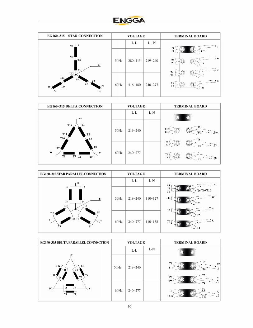
EG160~315 STAR CONNECTION VOLTAGE TERMINAL BOARD
L-L L - N
50Hz 380~415 219~240
60Hz 416~480 240~277
EG160~315 DELTA CONNECTION VOLTAGE TERMINAL BOARD
L-L L-N
50Hz 219~240
60Hz 240~277
EG160~315 STAR PARALLEL CONNECTION VOLTAGE TERMINAL BOARD
L-L L-N
50Hz 219~240 110~127
60Hz 240~277 110~138
EG160~315 DELTA PARALLEL CONNECTION VOLTAGE TERMINAL BOARD
L-L L-N
50Hz 219~240
60Hz 240~277

11
EG160~315 DOUBLE DELTA CONNECTION VOLTAGE TERMINAL BOARD
L-L L-M
50Hz 220~240 110~120
60Hz 240~277 120~138
EG160~315 ZIG-ZAG CONNECTION VOLTAGE TERMINAL BOARD
L-L L-M
50Hz 208~240 110~120
60Hz 240~277 120~138
EG355~500 STAR CONNECTION VOLTAGE TERMINAL BOARD
L-L L-N
50Hz 380~415 219~240
60Hz 416~480 240~277
EG355~500 DELTA PARALLEL CONNECTION VOLTAGE TERMINAL BOARD
L-L L-N
50Hz 219~240
60Hz 240~277
12
4.5 Protection
The generator supplied neutral cable is not connected to the frame. Should it is required, it can be connected. Inside the
terminal box, there is a earth terminal provided. There is a possibility during the complete generator set in operation,
over-speed, over-voltage, short-circuit and other possibilities can be occurred. Reliable protections are required. If running
on parallel operation, reverse power protection is also required.
During operation, it is required to follow strictly to the local regulations, laws and technical
Standards in force
5 STARTING UP
5.1 Check before staring up
After transportation, storage, installation and assembling of the complete machine, it is necessary to do a final check on all
the mechanical and electrical components before operation to ensure it is totally safe and properly protected.
5.1.1 Check the rotating rectifier set
It is required to test the diodes of the rotating rectifying set with a multi-meter. Prior to the testing, it is required to
disconnect all the connection cable of the diode. A good condition diode enables the current to flow only one direction, from
the anode to the cathode. Surge suppressor is a metal oxidation voltage-dependent resistance type and connected between
both incoming and outgoing cable of the main rotor. This surge suppressor is to protect the rotating diodes from damage
caused by high load changes or misuse.
5.1.2 Check the insulation
The generator has a very good insulation protection construction, unless it is being store for a long time or used in severe
climatic or atmospheric conditions, otherwise no other protection, for example heating is required. It is a good practice to
test the stator windings for ground insulation before starting the machine. If the ground resistance is below 2Mohm, then it is
necessary to dry the generator.
5.1.3 Check the earth connection
All the earth bolts in the generator support should be connected. Grounding has to be carried out using a copper wire of
suitable size, in compliance with applicable standards.
5.1.4 Check the connection
Standard generators are supplied with either 12 leads or 6 leads. The entry terminals cables in the terminal box is on the
right hand side. Terminals arrangement permits star series and star parallel connection. It is necessary when changing the
connection from star series to star parallel, to check and modify the connection to the AVR, according to the diagram
provided.
5.1.5 Check the final assembly
- check the engine and generator are properly alignment.
- check the inlet and outlet air passage is smooth and not being block by any big or large object or machinery. Also to
make sure there is no back pressure or hot air back circulation.
- check all the bolts are securely fastened and tighten and all protection are in proper.

13
- check there is any dirt or dirty particles or waste inside the generator.
- check by turning the rotor to ensure again that there is no touching in between.
A word of final advice to ensure everything is in proper conditions, it is a must to check thoroughly the machine
based on above recommendation before start to operate.
5.2 Commissioning
All generators are fully tested at the factory prior to delivery. All generators are factory set at star series connection, 400V at
1500rpm.
5.2.1 No load adjustment
When the prime mover reaches the rated speed, the generator should have also reaches the rated voltage. If there is a different
in the voltage level, it can be corrected by adjusting the AVR. All three phase voltage should also be stable and balance.
5.2.2 Load adjustment
To ensure the generator is in good condition, applied the load by increasing and decreasing the load to check the voltage
stability level, check all the control panel metering is functioning in proper condition and also check on the generator of any
abnormal condition.
After the above steps, the generator is safe to operate. Please note that it is required to unplug the AVR when the prime
mover is running at low speed for a long time, otherwise, it will damaged the AVR and the excitation windings.
The generator have dangerous parts when operating they have live and rotating components.
Therefore improper use, disconnection of protection devices and not sufficient inspection and
maintenance can cause in personal injury or property damage.
6 MAINTENENACE
If there is a routine maintenance and checking program, the generator will function in good condition. It is important to
ensure safe and trouble free conditions throughout the operation period. It is recommended to follow every maintenance
measures highlighted in this manual.
When running hours of the generator achieved 500 running hours, it is recommended to check the insulations and clean the
stator and rotor assembly. When achieved 1000 running hours, it is recommended to check the temperature rise, fan
assembly and bolt sets. It is recommended to have a fix maintenance schedule
6.1 General maintenance
- Generator should always be kept dry. In order to keep out of the humidity, please cover with cloth if not in used.
- Generator must be free from metal leftovers, drops, dust, acid-base steam or other harmful gases.
- During operation, the ventilation must be sufficient. Please ensure all openings are free and not be block by any
machinery or panel. Do not put anything on top of the alternator for it is bad for ventilation and heat elimination. Please
don’t remove the top terminal box cover.
- Please check the generator load from time to time. The load current should not over the rated current of generator.
When the load power factor is low, the excitation current should not over the rated value mentioned on the nameplate.
When the 3 phase load is not balance, the biggest phase current of that phase should not over the rated current.
- Please note the temperature of alternator bearing. The bearing temperature rise should not over 55K in general.
- During operation, the generator shall not over the rated speed, voltage and ampere. Should abnormal smells, strange
14
sound audible and excessive vibration detected, please stop the machine immediately and a thorough check up is required
before restart the machine.
6.2 Inspection and maintenance
- If the generator is not in use for some time, check the windings insulation. If it is lower than 2 Mohm, then it is
necessary to dry the generator and then repeat the test. If the grounding insulation still remains the same, then the
insulation has already aged and you should change the wire and insulation.
- Check the bearing and housing position to ensure there is no loose or wear and tear.
- check the airflow and internal condition. If inside the terminal box is too dusty, its required to be cleaned.
- check the alignment of the generator to the engine to make sure it is not out of alignment and also check the fan
assembly to ensure it is not deform.
- Check all cable connections especially the AVR side to make sure it is not loose.
All maintenance checking and servicing should be done after the machine is completely stop.
During maintenance, it is required to ensure all switches are turn to Off and also disconnect the
main power cables. To ensure safety, it is also recommended to place a Danger sign panel to keep
others well inform of any maintenance work on progress.
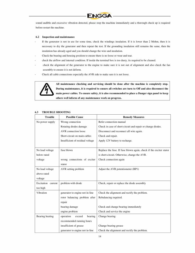
6.3 TROUBLE SHOOTING
Trouble Possible Cause Remedy Measures
No power supply Wrong connection
Rotating diodes damage
AVR connection loose
Short-circuit on main cables
Insufficient of residual voltage
Refer connection manual
Check in case of short-circuit and repair or change diodes.
Disconnect and reconnect all wire again.
Check and repair.
Apply 12V battery to recharge.
No load voltage
below rated
voltage
fuse blown
wrong connections of exciter
stator
Replace the fuse. If fuse blown again, check if the exciter stator
is short-circuit. Otherwise, change the AVR.
Check connection again
No load voltage
above rated
voltage
AVR setting problem
Adjust the AVR potentiometer (RP1)
Excitation current
too high
problem with diode Check, repair or replace the diode assembly
Vibration generator to engine not in-line
rotor balancing problem after
repair
bearing damage
engine problem
Check the alignment and rectify the problem.
Rebalancing required.
Check and change bearing immediately
Check and service the engine
Bearing heating operation exceed bearing
recommended running hours
insufficient of grease
generator to engine not in-line
Change bearing
Change bearing grease
Check the alignment and rectify the problem.
15
Generator heating overloaded
power factor too low
rpm too low
airflow problem
Reduce to the rated load
Adjust the load and adjust the ampere to the rated level
Adjust the speed to the rated speed
Check the fan assembly and ensure not obstruction
Voltage unstable AVR problem Check, adjust or change a new AVR
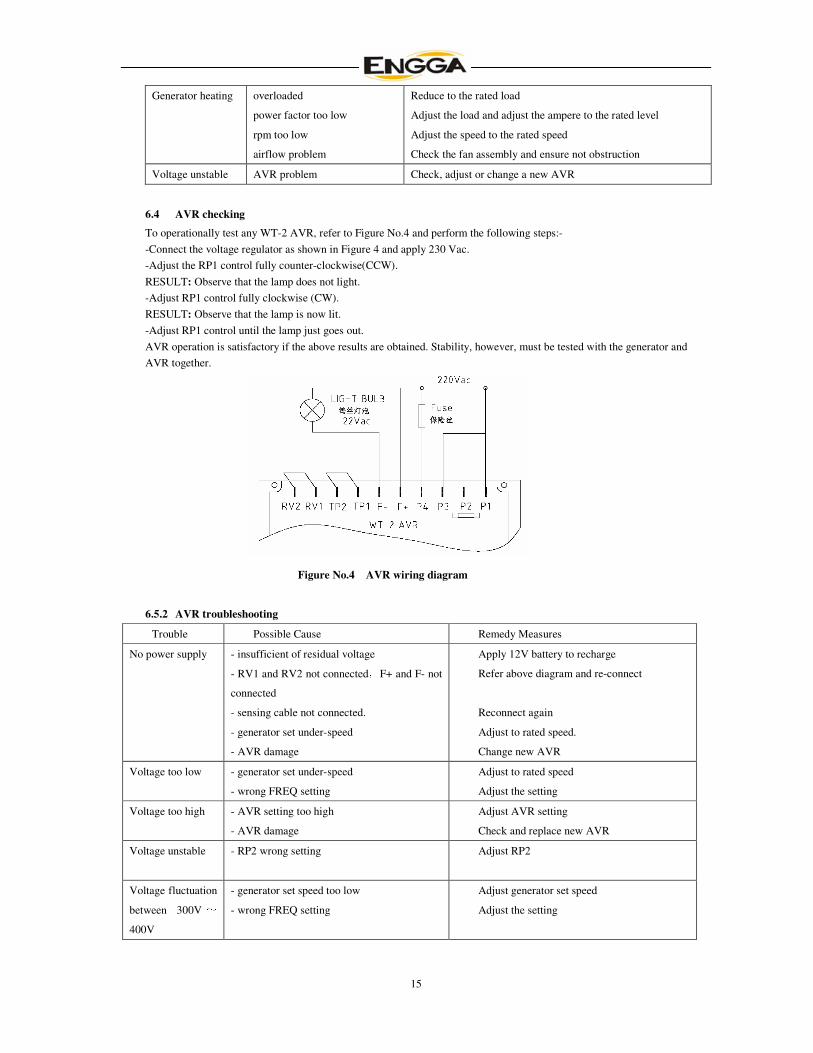
6.4 AVR checking
To operationally test any WT-2 AVR, refer to Figure No.4 and perform the following steps:-
-Connect the voltage regulator as shown in Figure 4 and apply 230 Vac.
-Adjust the RP1 control fully counter-clockwise(CCW).
RESULT: Observe that the lamp does not light.
-Adjust RP1 control fully clockwise (CW).
RESULT: Observe that the lamp is now lit.
-Adjust RP1 control until the lamp just goes out.
AVR operation is satisfactory if the above results are obtained. Stability, however, must be tested with the generator and
AVR together.
Figure No.4 AVR wiring diagram
6.5.2 AVR troubleshooting
Trouble Possible Cause Remedy Measures
No power supply - insufficient of residual voltage
- RV1 and RV2 not connected,F+ and F- not
connected
- sensing cable not connected.
- generator set under-speed
- AVR damage
Apply 12V battery to recharge
Refer above diagram and re-connect
Reconnect again
Adjust to rated speed.
Change new AVR
Voltage too low - generator set under-speed
- wrong FREQ setting
Adjust to rated speed
Adjust the setting
Voltage too high - AVR setting too high
- AVR damage
Adjust AVR setting
Check and replace new AVR
Voltage unstable - RP2 wrong setting Adjust RP2
Voltage fluctuation
between 300V ~400V
- generator set speed too low
- wrong FREQ setting
Adjust generator set speed
Adjust the setting

16
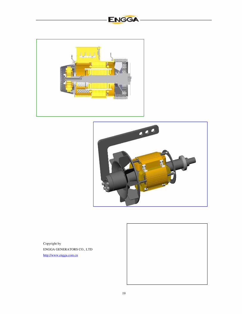
7 STRUCTURAL DRAWING
17
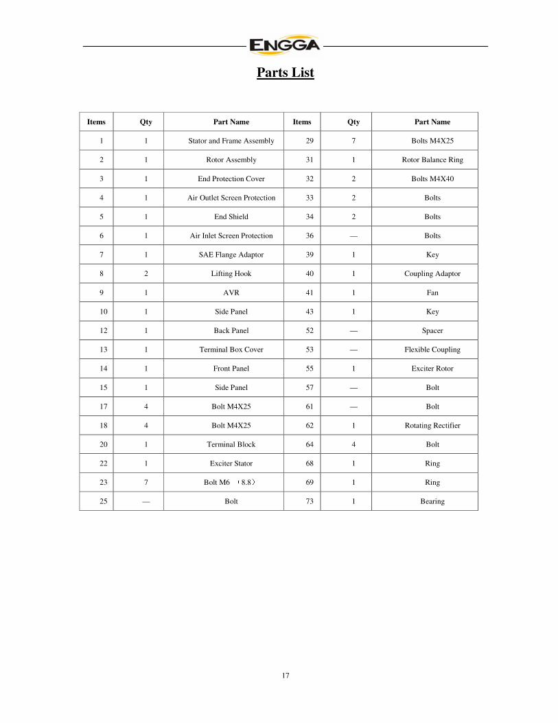
Parts List
Items Qty Part Name Items Qty Part Name
1 1 Stator and Frame Assembly 29 7 Bolts M4X25
2 1 Rotor Assembly 31 1 Rotor Balance Ring
3 1 End Protection Cover 32 2 Bolts M4X40
4 1 Air Outlet Screen Protection 33 2 Bolts
5 1 End Shield 34 2 Bolts
6 1 Air Inlet Screen Protection 36 — Bolts
7 1 SAE Flange Adaptor 39 1 Key
8 2 Lifting Hook 40 1 Coupling Adaptor
9 1 AVR 41 1 Fan
10 1 Side Panel 43 1 Key
12 1 Back Panel 52 — Spacer
13 1 Terminal Box Cover 53 — Flexible Coupling
14 1 Front Panel 55 1 Exciter Rotor
15 1 Side Panel 57 — Bolt
17 4 Bolt M4X25 61 — Bolt
18 4 Bolt M4X25 62 1 Rotating Rectifier
20 1 Terminal Block 64 4 Bolt
22 1 Exciter Stator 68 1 Ring
23 7 Bolt M6 (8.8) 69 1 Ring
25 — Bolt 73 1 Bearing

18
Important Notes
19
Copyright by
ENGGA GENERATORS CO., LTD
http://www.engga.com.cn