manual for selection and application of cured-in-place
TRANSCRIPT
COPYRIGHT
ACKNOWLEDGMENTS
Manual for selection and application of cured-in-place
pipe (CIPP) and spray liners for use in water pipe

The Australian Government, through the Cooperative Research Centre, provided funding for the Smart
Linings for Pipe and Infrastructure Project that produced this manual. The CRC Program supports
industry-led collaborations between industry, researchers and the community.
The WSAA Board would like to express its appreciation to the CRC, Project Participants and staff for
their contributions to the development and revision of this Manual.
The project was led by the Water Services Association of Australia (WSAA) and included the following
project partners, all of whom contributed expertise, labour, funding, products or trial sites to assist in the
delivery of this project.
Abergeldie Watertech
BASF Australia
Bisley & Company
Calucem GmbH
Central Highlands Water
City West Water Corporation
Coliban Region Water Corporation
Downer
GeoTree Solutions
Hunter Water Corporation
Hychem International
Icon Water
Insituform Pacific
Interflow
Melbourne Water Corporation
Metropolitan Restorations
Monash University
Nu Flow Technologies
Parchem Construction Supplies
Sanexen Environmental Services
SA Water Corporation
South East Water Corporation
Sydney Water Corporation
The Australasian Society for Trenchless
Technology (ASTT)
The Water Research Foundation
UK Water Industry Research Ltd (UKWIR)
Unitywater
University of Sydney
University of Technology Sydney
Urban Utilities
Ventia
Water Corporation
Wilsons Pipe Solutions
Yarra Valley Water

COPYRIGHT
DISCLAIMER
WSAA Manuals are published by Water Services Association of Australia Limited on the
understanding that:
• Water Services Association of Australia Limited and individual contributors are not
responsible for the results of any action taken on the basis of information in the Manual for
selection and application of cured-in-place pipe (CIPP) and spray liners for use in water pipe,
nor any errors or omissions.
• Water Services Association of Australia Limited and individual contributors disclaim all and
any liability to any person in respect of anything, and the consequences of anything, done or
omitted to be done by a person in reliance upon the whole or any part of the Manual for
selection and application of cured-in-place pipe (CIPP) and spray liners for use in water pipe.
PUBLICATION DETAILS
Published by:
Water Services Association of Australia Limited
Level 8 Suite 8.02
401 Docklands Drive
Docklands VIC 3008
ISBN [to be included in published version]
COPYRIGHT
Water Services Association of Australia will permit up to 20 percent of this Manual to be copie d for
use exclusively in house by purchasers of this Manual, for use in contract documentation and for
training purposes without payment of a royalty or giving advice to Water Services Association of
Australia Limited.
© Copyright 2021 by WATER SERVICES ASSOCIATION of Australia Limited All rights reserved.
5 WSA 201—2017-2.1
COPYRIGHT
FOREWORD
The Australian urban water industry commenced in the mid 1800’s and became a major builder of
infrastructure in the 1920’s, peaking in the post-World War II period. The industry has a large
portfolio of assets with a nominal written down replacement cost for fixed water supply and
sewerage assets exceeding $120 Billion. These infrastructure assets consist of in excess of
140,000 km of water mains, 120,000 km of sewer mains, approximately 260 water treatment plants
and 440 sewage treatment plants, as well as large numbers of water storage tanks and reservoirs,
water and sewage pumping stations and other associated facilities and structures.
Many of these assets rely upon linings to extend the life of existing pipes and associated
infrastructure. The water utilities collectively have acquired immense knowledge and experience in
the use of linings across a wide range of applications and environments. The i ndustry’s material
specialists have a long history of involvement in the development of technical standards and
specifications along with training and certification programs to ensure that quality products are
manufactured and supplied for application by competent contractors using appropriate surface
preparation and application techniques.
This first edition of this Manual was developed to consolidate current industry “most appropriate
best practice”. It is not intended to inhibit innovation. It does not purport to address all asset
management situations and/or options.
The clear benefits of this Manual and WSAA Codes, Standards, Specifications and Tools extend
beyond our members to the wider Australian community. The performance of network
infrastructure is fundamental to achieving excellence in community health, commerce and industry,
customer service, asset management and delivering sustainable water and sewerage services. The
Manual will make a practical contribution to better achieving these goals.
WSAA is ideally positioned to provide national leadership in actively prosecuting its National Codes
Initiative that commenced in 1997. As an industry association of the major urban water utilities in
Australia, WSAA’s members supply the majority of Australian residential, commercial and industrial
consumers with water and sewerage services. In developing Codes that articulate appropriate
planning, design and construction practices, WSAA is providing a valuable training resource that can
assist in building asset management capability and capacity necessary for the ongoing reliable and
successful performance of our network infrastructure.

COPYRIGHT
CONTENTS
1. INTRODUCTION 8 1.1 PURPOSE AND SCOPE 8 1.2 MANDATORY AND INFORMATIVE 8 1.3 ALTERNATIVE SOLUTIONS AND INNOVATIONS 8 1.4 USE OF THE MANUAL 8
During design or selection of lining systems 9 During lining application 9 During inspection and testing 9 During lining maintenance 9
1.5 AMENDMENTS AND SUPPLEMENTS 9 1.6 REFERENCED DOCUMENTS 10 1.7 TERMS AND DEFINITIONS 10 1.8 ABBREVIATIONS 13
2 LINER INFORMATION 14 2.1 LINER CLASS AND PERFORMANCE REQUIREMENTS 14 2.2 CURED-IN-PLACE PIPE (CIPP) 14 2.3 POLYMERIC SPRAY LINING 15 2.4 SITE SET UP 15 2.5 SOURCING AND USING LINING PRODUCTS 16
3 QUALITY ASSURANCE 16 3.1 INTRODUCTION 16 3.2 APPROVED APPLICATOR/INSTALLER 16 3.3 SUPPLIER’S SPECIFICATION 16 3.4 INSPECTION AND TEST PLAN (ITP) 17 3.5 TRIAL APPLICATION 17
4 SELECTION OF LININGS 17 4.1 OVERVIEW OF LINER SELECTION PROCESS 18 4.2 HOST PIPE PRIORITISATION AND SELECTION 18 4.3 HOST PIPE CONDITION EVALUATION 18 4.4 LONG-TERM PERFORMANCE OF LINER AND HOST PIPES 20 4.5 FINAL RECOMMENDATION 21
5 SURFACE PREPARATION 21 5.1 INTRODUCTION 21 5.2 METHODS OF SURFACE PREPARATION 22
Swabbing 22 Abrasive blast cleaning 22 Forced Air Vortex 22 Low and High Pressure Water Jetting 23 Rodding 23 Pipe Scraping 23 Root Cutters 24 Plunger 24 Additional Notes on Spray Lining 24
5.2.1.1 Reducing blistering 24
5.2.1.2 Preventing delamination 24
5.3 SURFACE PREPARATION QUALITY ASSURANCE 25 5.4 ENVIRONMENTAL 25

COPYRIGHT
6 LINING APPLICATION 25 6.1 GENERAL 25 6.2 APPLICATION CONSTRAINTS 25
Pulling Forces 26 Host pipe bends and connections 26
6.3 TRANSPORTATION AND STORAGE 27 6.4 MIXING COMPONENTS 27 6.5 RESIN DISTRIBUTION (CIPP) 28 6.6 FILM THICKNESS (SPRAY LINING) 28 6.7 LINER FINISH 28
For CIPP liners 28 For spray liners 28
6.7.1.1 Measurement Options 28
6.7.1.2 Reducing ringing effect 29
6.8 REINSTATING SERVICE CONNECTIONS 29 External Reinstatement 29 Internal Reinstatement 29 Achieving Water-tightness 30
6.9 HOST PIPE CONNECTIONS (END SEALS) 30 6.10 LINING APPLICATION QUALITY ASSURANCE 31
7 QUALITY CONTROL – INSPECTION AND TESTING 31 7.1 INTRODUCTION 31 7.2 INSTALLATION ISSUES 32 7.3 QUALITY CONTROL RECORDS 35 7.4 INSPECTION AND TESTING METHODS 36
Testing and performance requirements 36 Measurement of potential defects 38 Rectification of defects 38
7.5 SPRAY LINERS 38 7.5.1 SPRAY LINER THICKNESS REQUIREMENTS 38 7.5.2 SPRAY LINER TENSILE AND FLEXURAL PROPERTIES 40 7.6 CIPP LINERS 40 7.6.1 CIPP LINER THICKNESS 40 7.6.2 CIPP LINER TENSILE AND FLEXURAL PROPERTIES 41
8 RETURN TO SERVICE OF NEWLY LINED PIPE 41 8.1 HYDROSTATIC PRESSURE TESTING 41
Test Pressures 41 8.2 WATER QUALITY TESTING 41 8.3 DISINFECTION AND WATER FLUSHING 41
9 LINED ASSET AS-CONSTRUCTED INFORMATION 42
10 LINER MAINTENANCE 42 10.1 REPAIRS TO NEWLY INSTALLED LINERS 42 10.2 MAINTENANCE LINING 42 10.3 NEW SERVICE CONNECTIONS 43
11 APPENDIX 1: STRUCTURAL CLASSIFICATION OF LINERS 44
12 APPENDIX 2 EXAMPLES OF INSPECTION AND TEST PLANS 46

COPYRIGHT
1. INTRODUCTION
1.1 PURPOSE AND SCOPE
This Manual is intended for those who are specifying and applying cured-in-place pipe or polymeric
spray lining products for Water Agency facilities and network infrastructure.
This Manual sets out standard requirements to ensure that a high-quality level of workmanship and
long-term performance is achieved.
This Manual refers to, and should be used in conjunction with, relevant Australian and International
Standards, and other documentation issued by the product suppliers. Together they facilitate the
development of integrated specifications for the Designer and Applicator. If there is any
contradiction between this Manual and product supplier’s documentation, it should be referred to
the Water Agency for resolution.
1.2 MANDATORY AND INFORMATIVE
This Manual provides a mixture of mandatory and informative statements. In some cases, they are
deliberately combined throughout the Manual to provide relevant context and enable better
understanding of the mandatory requirements.
Where an obligation is given and it is not stated who shall undertake this obligation, it shall be
undertaken by the Applicator. Where a submission, request or proposal is required and it is not
stated who the recipient shall be, it shall be provided by the Applicator to the Water Age ncy for
approval.
The use of this Manual does not relieve the Supplier and Applicator of any responsibility for
delivering the required quality level of design, materials, workmanship and performance that they
have been engaged to provide.
1.3 ALTERNATIVE SOLUTIONS AND INNOVATIONS
Any alternative materials, design, work methods and processes that do not comply with the specific
requirements of this Manual, or are not mentioned in this Manual, but give equivalent performance
outcomes to those specified, are not necessarily prohibited. Written approval from the Water
Agency shall be sought prior to adopting the alternative solutions.
1.4 USE OF THE MANUAL
This manual is intended for use in conjunction with:
• The Water Agency’s construction specification, including WHS requirements.
• The applicable Water Industry Standard, i.e.
o WSA XXX Water Industry Standard for Cured-in-place pipes (CIPP) used for the
renovation of drinking water pipes; or
COPYRIGHT
o WSA XXX Water Industry Standard for polymeric spray lining materials used for the
renovation of drinking water pipes.
• The Pipe Evaluation Platform
o Available at [final site to be included in published version, currently
available: https://pipes.monash.edu/].
The following scenario illustrates a typical use of the Manual.
During design or selection of lining systems
The Water Agency representative, e.g. asset manager, designer, or project manager, uses this
Manual, the Water Industry Standards and Decision Tools as input for the design specification.
Depending on the criticality of the asset, the representative may include requirements around
condition assessment prior to specifying a liner.
During lining application
The Applicator, who is typically a contractor, is engaged to apply the specified lining product in the
design specification. The Applicator shall:
(a) follow the methodology specified in this Manual;
(b) apply the specified lining system; and
(c) use approved materials and products only (refer to Water Agency).
During inspection and testing
Lining inspector(s) engaged or employed by the Applicator or Project Manager should refer to
Section 7: Inspection and Testing.
During lining maintenance
The Designer, Project Manager, Asset Manager or Operator uses this Manual, in particular Section
4: Selection of Linings, as input for the maintenance specification.
1.5 AMENDMENTS AND SUPPLEMENTS
Comments and suggestions for improvement are welcome by emailing [email protected].
This Manual will be revised from time to time. Minor amendments may be made between revisions.
Users may register their interest so that amendments can be emailed directly and proposed changes
can be provided for their review and comments. To register, please submit name, position, company
and contact details to [email protected].

COPYRIGHT
1.6 REFERENCED DOCUMENTS
The following documents are referenced in this Manual.
AS/NZS
4020 Testing of products for use in contact with drinking water
ISO 9000 Quality management systems — Fundamentals and vocabulary
ISO 9001 Quality management systems — Requirements
ASTM
F 1216 Standard Practice for Rehabilitation of Existing Pipelines and Conduits by the
Inversion and Curing of a Resin-Impregnated Tube
AWWA
C950 Fiberglass Pressure Pipe
1.7 TERMS AND DEFINITIONS
For the purpose of this Manual, the following terms and definitions apply.
average thickness The mean of measurements taken to record liner thickness at the “I”
stage in accordance with this manual
cast iron Includes grey cast iron, ductile cast iron, malleable cast iron,
austenitic cast iron etc.
carrier material porous component of the liner, which carries the liquid resin system
during insertion into the pipe being renovated and forms part of the
installed lining system once the resin has been cured
composite combination of cured resin system carrier material and/or
reinforcement excluding any internal or external membranes
curing process of resin polymerization, which may be initiated or accelerated
by the use of heat or exposure to light
design thickness required wall thickness of the composite, excluding any abrasion
layer, as determined by structural design
drinking water Drinking water includes water at any stage of treatment and at any
point in the transfer, storage, distribution and reticulation system up
to the point of customer connection
COPYRIGHT
dry film thickness (DFT) The dry film thickness of a lining remaining on the surface and above
the peaks of the surface profile when the lining or system has
hardened and cured
inversion process of turning a flexible tube or hose inside out by the use of fluid
(water or air) pressure
inverted-in-place
insertion
method whereby the impregnated lining tube is introduced by
inversion to achieve simultaneous insertion and inflation
lining tube the combined components of the liner prior to curing, i.e. all of the
following that apply in the product used: carrier material, reinforcing
layer(s), internal and/or external membrane, mixed uncured resin
applied to carrier material
liner Lining pipe after installation
liner thickness the liner wall thickness following installation and curing (‘I’ s tage)
maintenance routine work undertaken to ensure the continuing performance of an
asset
operating pressure The pressure that the pipe to be lined usually sustains during normal
operation.
minimum dry film
thickness
The minimum acceptable dry film thickness for each lining layer or for
the whole lining system
minimum thickness the minimum wall thickness required in the product supplier’s
documentation
rehabilitation measures for restoring or upgrading the performance of existing
pipeline systems, including renovation, repair and replacement
renovated pipeline the existing pipeline system plus the installed liner used to renovate
it.
renovation work incorporating all or part of the original fabric of the pipeline, by
means of which its current performance is improved
repair rectification of local damage
replacement construction of a new pipeline, on or off the line of an existing
pipeline, where the function of the new pipeline system incorporates
that of the old
reservoir A tank or similar storage supplying water to a reticulation zone

COPYRIGHT
specified thickness the specified final wall thickness of the liner resin system once
installed and cured (‘I’ stage) and includes multiple
applications/passes where used
Water Agency An authority, board, business, corporation, council or local
government body with the responsibility for planning or defining
planning requirements, for defining and authorising design
requirements, for defining and authorising construction requirements
and for operating and maintaining or defining operation and
maintenance requirements for a water supply and/or sewerage
system, water and sewage treatment facilities, outfalls, dams,
reservoirs and storages, etc.

COPYRIGHT
1.8 ABBREVIATIONS
% percentage
AC Asbestos cement
AS Australian Standard
AS/NZS Australian/New Zealand Standard
ASTM American Society for Testing Materials
AWWA American Water Works Association
CI Cast iron
CICL Cast iron cement lined
CIPP Cured-in-place pipe
DFT dry film thickness
DN nominal diameter related to the outside diameter
ISO International Standards Organisation
ITP inspection and test plan
km kilometre
mm millimetre
MPa megapascal
QC quality control
SSPC Society of Protective Coatings
UV ultraviolet
WFT wet film thickness
WHS work health and safety
WSAA Water Services Association of Australia
COPYRIGHT
2 LINER INFORMATION
This manual considers the application of two types of lining systems: cured-in-place pipe and
polymeric spray liners. This section provides a brief overview of the lining systems, classes and
sourcing and approval requirements. Detailed information and requirements for each system can
be found in the relevant Water Industry Standard:
• WSA XXX Water Industry Standard for Cured-in-place pipes (CIPP) used for the
renovation of drinking water pipes; or
• WSA XXX Water Industry Standard for polymeric spray lining materials used for the
renovation of drinking water pipes.
2.1 LINER CLASS AND PERFORMANCE REQUIREMENTS
There are four different liner classes (A-D), where class A is a fully structural liner, classes B and C
are semi-structural and class D is non-structural. For additional detail about these classes refer to
appendix A.
The class rating of the liner is dependent on its ability to perform functions at the maximum
allowable operating pressure. The maximum operating pressure may vary across assets. This
variation can impact liner class, for example, a liner may be rated as a Class A liner at lower
maximum operating pressures and a Class B liner at higher maximum operating pressures.
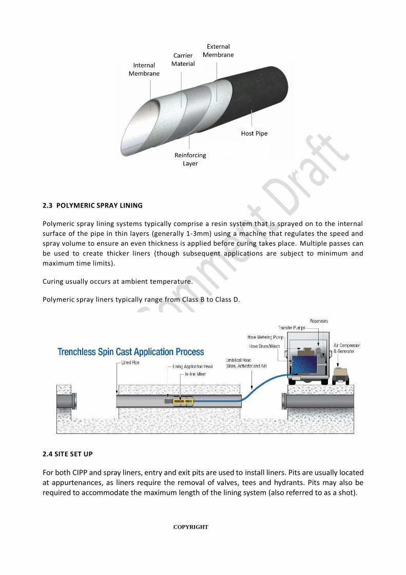
2.2 CURED-IN-PLACE PIPE (CIPP)
CIPP lining systems typically comprise of a fibrous carrier impregnated with a thermosetting resin.
The lining tube may be pulled directly into the host pipe or inverted-in-place as it is inserted. Water
pressure, swabs, steam or air may be used to inflate the tube so it expands tightly against the host
pipeline before being cured in place.
Curing may be carried out by the application of heat, UV radiation, visible li ght, or at ambient
temperature.
CIPP liners typically range from Class A to Class C.
COPYRIGHT
2.3 POLYMERIC SPRAY LINING
Polymeric spray lining systems typically comprise a resin system that is sprayed on to the internal
surface of the pipe in thin layers (generally 1-3mm) using a machine that regulates the speed and
spray volume to ensure an even thickness is applied before curing takes place. Multiple passes can
be used to create thicker liners (though subsequent applications are subject to minimum and
maximum time limits).
Curing usually occurs at ambient temperature.
Polymeric spray liners typically range from Class B to Class D.
2.4 SITE SET UP
For both CIPP and spray liners, entry and exit pits are used to install liners. Pits are usually located at appurtenances, as liners require the removal of valves, tees and hydrants. Pits may also be required to accommodate the maximum length of the lining system (also referred to as a shot).

COPYRIGHT
Depending on the system used a variety of trucks and equipment will be required. Traffic management is generally required, though significant interruptions for road users, e.g. closures, can usually be avoided.
2.5 SOURCING AND USING LINING PRODUCTS
Where available, all products used within a selected lining system should originate from a single
supplier. Importantly, they shall be compatible with each other and be applied strictly in accordance
with this Manual, the relevant Water Industry Standard, and the Supplier’s specification.
Individual Water Agencies may require lining system approval, in which case only approved products
shall be used. A list of Water Agency approved or deemed-to-comply lining products may be
available. Where a list of approved products is not available, consult the Water Agency. Other
products that can demonstrate equivalent or superior performance may be considered for approval
by the Water Agency, the onus to acceptably demonstrate performance remains at all times with
the Supplier and Applicator. The Water Agency reserves the right to make changes to the content
of their approved products list without giving notice or explanation.
3 QUALITY ASSURANCE
3.1 INTRODUCTION
The Applicator shall use a Quality Management System for the works. The Quality Management
System shall be compliant with a standard acceptable to the Water Agency, such as ISO9001.
Each Water Industry Standard nominates default quality assurance requirements related to that
product type.
3.2 APPROVED APPLICATOR/INSTALLER
Surface preparation and lining application shall be undertaken by the applicator and/or installer.
The Applicator shall demonstrate that its personnel have the required industry certification,
training, track records and equipment in applying the nominated product.
3.3 SUPPLIER’S SPECIFICATION
Prior to the commencement of the work, a work method statement prepared by the lining supplier
(Supplier) shall be submitted by the Applicator for each lining system proposed for use. It shall
contain the requirements for the supply, storage, mixing, equipment, surface preparation,
application, WFT, DFT, coating thickness values, recoat times, curing, inspection, testing, repair of
defects, and details of any deviation from this specification. Application shall not commence
without the approval of the Water Agency.
The requirements in this document shall take precedence over the Supplier’s specification and
associated documents, unless otherwise approved by the Water Agency.

COPYRIGHT
3.4 INSPECTION AND TEST PLAN (ITP)
Prior to commencement of the work, the lining Applicator shall prepare an ITP for each lining system
and structure to be coated. The ITP shall show the type, sequence and number of tests to be taken
in each area and how the pass or rejection criteria are determined. It shall also identify “hold points”
and “witness points” required throughout the works. It shall be submitted to the Water Agency for
approval.
The approved inspection and testing methods are detailed in Section 7 and examples of ITP’s are
given in Appendix 2 of this document.
3.5 TRIAL APPLICATION
A trial application may be required if there are uncertainties regarding the success of the proposed
methodology.
The location and extent of the trial shall be selected in consultation with the Water Agency, to
reflect the actual work conditions. The trial shall include proposed methods of surface cleaning,
surface restoration, lining application and acceptance testing. The recording of observations and
reporting of the trial shall be agreed with the Water Agency.
If it becomes apparent during the trial that adjustments are required to the proposed products,
equipment or work methods, the adjustments shall be submitted for approval.
The Applicator shall prepare and submit to the Water Agency a trial report for consideration and
approval by the Water Agency.
4 SELECTION OF LININGS
For a liner to perform effectively it is important to select a liner type and class that is appropriate
for the host pipe condition and original pipe material in order to make sure it meets the intended
design life requirement of the water agency.
An online tool, the Pipe Evaluation Platform, has been developed to assist in making these decisions
and is available for use at [final site to be included in published version, currently
available: https://pipes.monash.edu/].
This section provides an overview of the selection process used in the P ipe Evaluation Platform. It
is recommended that the online tool is used when selecting liners. The tool considers many factors
when assessing the type of product that will be suitable for the expected pipe conditions.
For more information on liner classes refer to Appendix 1.

COPYRIGHT
4.1 OVERVIEW OF LINER SELECTION PROCESS
4.2 HOST PIPE PRIORITISATION AND SELECTION
The pipe ranking module in the Pipe Evaluation Platform allows users to either:
a) Use the Monash pipe ranking model to prioritise which pipes to renew; or
b) Upload data from a separate pipe ranking tool.
When using the Monash pipe ranking model, users are required to upload pipe data from two csv
files (pipe asset file and failure input file). This data is used by the Platform to prioritise the pipes
for either lining, repair or replacement.
When uploading the data from a separate pipe rank ing tool, a particular format shall be used (refer
website for details). This data is then used in subsequent modules.
4.3 HOST PIPE CONDITION EVALUATION
Evaluating the condition of the host pipe is important in order to be able to determine what lining
systems will be fit for purpose and how long they will last.
The host pipe condition evaluation module allows users to either:
a) Upload available pipe data and calculate expected pipe condition.
Final recommendation
Assess feasibility, costs and liner imperfections to give final recommendation
Long-term performance of liner and host pipe
Evaluate degradation of liner and host pipe over an intended design life
Inital liner recommendations
Recommend suitable liner types based solely on current host pipe condition
Host pipe condition evaluation
Evaluate host pipe defects or failure history using available utility data
Host pipe prioritisation and selection
Select suitable pipe segments/zones from utility for ranking

COPYRIGHT
b) Upload condition assessment data.
Often condition assessment is not a cost effective way to manage non-critical assets. In this case
pipe data can be uploaded via a csv file and used to calculate the expected size of the defects in the
pipe based on cohort data and known deterioration rates.
Table 1: Data requirements where no condition assessment available
Required Data Optional Data
Installation year
Material type
Pressure
Diameter
Previous failure year
Failure type
Soil type
Leak rate
Table 2: Recommended data to capture in condition assessments
Data common to all pipes
Essential Condition Assessment Items
Pipe material
Construction year
Diameter (ID and OD)
Wall thickness
CML thickness (if present)
Length
Operating pressure
Previous lining type and thickness, e.g. CML
Soil Type
Optional Condition Assessment Items
Depth (cover to crown)
Surge pressure
Temperature change (water temp. variation)
Groundwater depth (from groundwater
surface to crown of pipe)
External and internal deterioration levels
(see options below)
Metallic Pipes AC Pipes
Scanned thickness maps, or
Sand/grit blasted samples.
Phenolphthalein wall thickness, or
CT scans.

COPYRIGHT
Where a parameter is not captured, the Pipe Evaluation Platform will estimate a value based on the
data available.
The Pipe Evaluation Platform manuals contain detailed information on what data is recommended
for collection and required format. Initial liner recommendations
The Initial Liner Recommendations module uses the condition assessment established in the
previous module to assign each pipe a condition grade based on its level of deterioration. This
condition grade is used for an initial liner type recommendation.
The initial liner type is used as a basis for long-term performance calculations in subsequent
modules.
4.4 LONG-TERM PERFORMANCE OF LINER AND HOST PIPES
The Long-term Performance of Liner and Host Pipes module is intended to assist a Water Agency in
determining how to meet its service life requirements for a liner, or how to vary service life
requirements to optimise costs.
The module allows users to:
a) Determine the required liner thickness, by varying the intended service life.
b) Estimate the liner service life, by varying the liner thickness.
The module calculates the options with consideration of liner type (CIPP or Spray), liner class,
various failure modes (creep, creep rupture and fatigue), and various deterioration mechanisms in
the host pipe material.
For spray liners, the design service life may be varied by changing the thickness of the application.
This can allow utilities to balance cost and service life requirements. Guidance should also be sought
from the product supplier.
Examples
• Pipe A will be upgraded in 5 years’ time to service a future development, the design life is
5 years. Use the tool to calculate the minimum thickness required.
• What is the expected service life for Pipe B if a 3mm spay liner is used? Use the tool to
calculate the answer based on the individual pipe details provided.
• Will the CIPP liner recommended by Company XYZ last for 50 years? Use the tool to calculate
the expected service life based on the class and thickness of the liner plus the individual pipe
details provided.
A liner may require maintenance over the duration of its service life. The serviceability limit states
relating to lined structures are defined as:
(a) Permanent damage to the lining due to corrosion, cracking or fatigue, which significantly
reduces the structural strength or useful service life of the structure.
COPYRIGHT
(b) The end of a structures service life is defined to occur when:
(i) Deterioration progresses to a level that makes the structure unsafe or unserviceable; or
(ii) The level of maintenance necessary to maintain the functionality of the structure becomes uneconomical.
4.5 FINAL RECOMMENDATION
Once the preferred lining system has been determined the Long-term Performance of Liner and Host
Pipes module can also be used to conduct an NPV analysis (user to supply cost data) and a feasibility
check.
The feasibility check takes into account the number of bends, laterals, service connections,
hydrants, etc. that can cause a change in the pipe. These can affect the lining process as they can
increase costs due to extra digging or robotics. Some liners are not suitable for either bends or
reductions/increases in diameter and this shall be examined before a selection is made. Users can
input the information or upload information into the module.
5 SURFACE PREPARATION
5.1 INTRODUCTION
Surface preparation is a key component of successful pipe lining. The original surface of the pipeline
shall be prepared in such a way as to provide the best lining surface. The requirements for the
surface may vary depending on the liner, for example when lining pipes with a cement mortar lining
(CML) some liners perform best if the CML is saturated. The liner supplier’s documentation shall be
consulted to determine the surface preparation requirements.
While some liners perform better with a saturated CML, standing water usually causes bonding
issues for CIPP and spray liners. Water ingress that causes standing water shall be monitored and
stopped before lining commences.
In general, a smooth internal bore and clean surface is the objective when cleaning the pipe, as any
protrusions into the pipeline introduce a risk that the liner will become stuck and tear, or introduce
folds/bulges into the liner which may introduce localised weak points. Completely reducing
protrusions may not be possible in all cases.
The surface preparation method, or combination of methods, shall be selected considering the
condition of the structure, the potential contaminants present, access to perform the work and the
required surface cleanliness and profile. Consideration shall be given to the final state of the pipe’s
internal surface prior to lining, e.g. some liners are best applied on top of a damp CML.
Where existing coatings show visible symptoms of deterioration they shall be removed prior to
lining.
CCTV is required before and after surface preparation works.

COPYRIGHT
5.2 METHODS OF SURFACE PREPARATION
Swabbing
Swabbing shall be conducted as per WSA 03 – Water Supply Code of Australia requirements.
Swabbing involves inserting a section of foam into a water main and using the flow of water to push
it towards a discharge point.
Swabbing is useful for cleaning the internal pipe surface of dirt and other foreign material. Swabbing
is unlikely to cause damage to the existing pipe, which may be especially important for heavily
degraded or AC pipes.
Swabbing is not always effective for removing large amounts of accumulated material, or material
that has become attached to the pipe, such as tuberculosis (corrosion).
Abrasive blast cleaning
Abrasive blast cleaning activity and equipment shall conform to AS 1627.4. This shall be achieved
by compliance with the relevant Safe Work Australia Code of Practice, i.e. Abrasive Blasting Code of
Practice.
Abrasive blasting involves forcing abrasive material via a medium, e.g. compressed air, water, etc.,
on to a surface a high speed in order to clear the surface, or remove the top layers of a surface.
Abrasive blast cleaning using a liquid or liquid/air mix is often referred to as “wet abrasive blasting”.
Abrasive blasting can be useful when internal pipe corrosion is difficult to remove. Wet abrasive
blasting can reduce the amount of dust created during the blasting process.
Abrasive blasting can cause health risks depending on the material being blasted. Control measures
shall be in place to ensure WHS requirements are met. Abrasive blasting shall not be used with
asbestos cement pipes, as it creates friable asbestos material.
Abrasive blast cleaning includes sand blasting and wet abrasive blasting.
Forced Air Vortex
Forced air vortex cleaning of pipes involves the use of a system that creates low pressure, high
velocity, turbulent air flow through the empty pipe. If removing hard deposits, such as corrosion
build up (tuberculation), an aggregate is introduced that impacts hard deposits as it passes. If
removing soft deposits, such as manganese or biofilm, water droplets are introduced.
There may be size restrictions in the use of these technologies to smaller pipelines , e.g. ≤DN300.
Often long lengths of pipe can be cleaned in each operation, e.g. 1km or more.
If using aggregates with the forced air vortex method, it is considered a form of abrasive blasting
and equipment shall conform to AS 1627.4. This shall be achieved by compliance with the relevant
Safe Work Australia Code of Practice, i.e. Abrasive Blasting Code of Practice.

COPYRIGHT
Low and High Pressure Water Jetting
Low and high pressure water jetting shall be carried out in accordance with AS/NZS 4233, and with
reference to:
• Safe Work Australia Guide for Managing Risks from High Pressure Water Jetting
• Plastic Pipes: POP205: PIPA Industry Guidelines for Water Jet Cleaning of Plastic Pipes.
• Metalic Pipes: NACE No. 5/SSPC-SP 12 Surface Preparation and Cleaning of Metals by
Waterjetting Prior to Recoating.
• AC Pipes: Water jetting shall not be used on asbestos containing materials.
Low and high pressure water jetting involves using a pump to force water through a 12 -25mm hose
and out of a specially designed nozzle. Holes in the rear of the nozzle propel and rotate it through
the pipe, removing obstructions and scouring the pipe walls. Removing the nozzle flushes debris
back to the point of entry for removal.
Low and high pressure water jetting is useful to remove debris build up in a pipe, remove corrosion
products and clean surfaces.
Sometimes debris or corrosion products have solidified on the internal pipe surface too hard for
water jetting to be effective. In these cases a more mechanical method, such as pipe scraping, may
be required. High pressure water jetting can cause damage to pipes, especially where the pipe is
already in a degraded state. Degraded asbestos cement pipes can be particularly vulnerable to this
type of damage.
Rodding
Rodding involves ramming a flexible rod with an attached rotating blade, auger or corkscrew shaped
tool on the end down the sewer to dislodge any blockages. The rod can be either electrically or
pneumatically driven into the pipeline. Another approach to Rodding uses heavy duty spinning
cables that turn blades clockwise and counter-clockwise to remove a blockage.
Rodding is most suitable for removing hard physical blockages from the pipeline, it is less effective
are removing soft physical blockages.
Pipe Scraping
A pipe scraper consists of steel body, a towing eye at each end and steel hook-shaped blades
branching from the body at various angles. This arrangement allows the full internal pipe surface to
be scraped.
A pipe scraper us useful for removing build-up of internal corrosion, or tuberculation, and is typically
used for unlined cast iron pipes, or pipe where a cement mortal lined pipe is severely corroded.
Pipe scrapers are less suitable for pipes that already have a lining, such as cement mortar lining, as
they are likely to damage sections of lining create a non-uniform, rough and inconsistent surface
for the new liner to adhere to.
COPYRIGHT
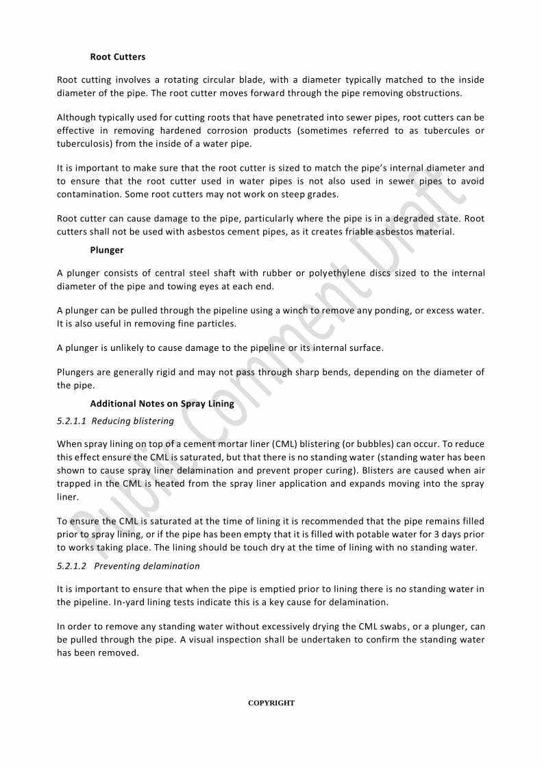
Root Cutters
Root cutting involves a rotating circular blade, with a diameter typically matched to the inside
diameter of the pipe. The root cutter moves forward through the pipe removing obstructions.
Although typically used for cutting roots that have penetrated into sewer pipes, root cutters can be
effective in removing hardened corrosion products (sometimes referred to as tubercules or
tuberculosis) from the inside of a water pipe.
It is important to make sure that the root cutter is sized to match the pipe’s internal diameter and
to ensure that the root cutter used in water pipes is not also used in sewer pipes to avoid
contamination. Some root cutters may not work on steep grades.
Root cutter can cause damage to the pipe, particularly where the pipe is in a degraded state. Root
cutters shall not be used with asbestos cement pipes, as it creates friable asbestos material.
Plunger
A plunger consists of central steel shaft with rubber or polyethylene discs sized to the internal
diameter of the pipe and towing eyes at each end.
A plunger can be pulled through the pipeline using a winch to remove any ponding, or excess water.
It is also useful in removing fine particles.
A plunger is unlikely to cause damage to the pipeline or its internal surface.
Plungers are generally rigid and may not pass through sharp bends, depending on the diameter of
the pipe.
Additional Notes on Spray Lining
5.2.1.1 Reducing blistering
When spray lining on top of a cement mortar liner (CML) blistering (or bubbles) can occur. To reduce
this effect ensure the CML is saturated, but that there is no standing water (standing water has been
shown to cause spray liner delamination and prevent proper curing). Blisters are caused when air
trapped in the CML is heated from the spray liner application and expands moving into the spray
liner.
To ensure the CML is saturated at the time of lining it is recommended that the pipe remains filled
prior to spray lining, or if the pipe has been empty that it is filled with potable water for 3 days prior
to works taking place. The lining should be touch dry at the time of lining with no standing water.
5.2.1.2 Preventing delamination
It is important to ensure that when the pipe is emptied prior to lining there is no standing water in
the pipeline. In-yard lining tests indicate this is a key cause for delamination.
In order to remove any standing water without excessively drying the CML swabs , or a plunger, can
be pulled through the pipe. A visual inspection shall be undertaken to confirm the standing water
has been removed.

COPYRIGHT
5.3 SURFACE PREPARATION QUALITY ASSURANCE
The applicator shall maintain records that document compliance with the requirements in this section,
summarised as follows:
(a) CCTV inspection prior to surface preparation works.
(b) Record surface preparation method(s) used.
(c) CCTV inspection following surface preparation works.
(d) For spray liners:
(i) For cement mortar lined pipes: record CML soaking time, time pipe drained, and time pipe lined.
(ii) For all applications: record if any standing water present.
These are the minimum requirements and are listed in the relevant ITP in Appendix 2. Suppliers may
have additional requirements that need to be met. Where this is the case the Applicator’s
documentation shall be amended to include these requirements.
5.4 ENVIRONMENTAL
Different cleaning techniques use different mediums, e.g. air or water, and may produce material
that requires disposal, e.g. water filled with particulates from pipe cleaning. Waste cleaning material
shall be disposed of to an appropriate facility, or in accordance with the Water Agency’s waste
management requirements.
6 LINING APPLICATION
6.1 GENERAL
Linings application shall be performed by competent and experienced personnel. The Applicator
shall provide appropriate supervision to ensure the specified standard of surface preparation has
been achieved (see section 5) and the lining application requirements are being followed.
Only use equipment that is recommended and/or approved by the lining supplier when applying the
lining product.
All equipment shall be dedicated for work on potable water infrastructure to prevent cross -
contamination from sewer lining equipment.
Where lining is applied by spraying, the requirements contained in Safe Work Australia Model Spray
painting and Powder Coating Code of Practice shall be followed.
6.2 APPLICATION CONSTRAINTS
Lining application shall not proceed if one or more of the following conditions exists , unless written
approval is obtained by the water agency:
(a) Diameter variation outside liner tolerance.

COPYRIGHT
(b) Ambient temperature, or other conditions, are outside the acceptable range for resins
(provided by supplier).
(c) Internal pipe defects are larger than lining system can span during installation (repair required
prior to lining).
Where particular conditions must be maintained to ensure that the liner cures correctly the
Applicator shall ensure these conditions are maintained for the duration of the curing period and
include evidence in its quality assurance documentation.
Internal diameter variation
It is recommended to check the internal diameter (ID) of the pipe to be lined. The ID of a pipe is
important information, as it allows the liner to be made to the correct size (in the case of CIPP) to ensure
good contact with the host and avoid excessive folds/wrinkle, avoid shadow effects and incomplete
coverage for spray liners and variations can also cause equipment to get stuck.
Class A CIPP liners are able to span short sections, e.g. a burst repair with larger ID, without contact with
the host pipe. However, any service connections shall be moved prior to lining (for internal
reconnection), or reconnected via excavation following the liner installation.
For other situations and liner types, planning an excavation for launch and retrieval pit at the location of
change in diameter will allow for adjustments to equipment or liner size for the different internal
diameter.
Pulling Forces
Some types of CIPP lining tubes are pulled through the host pipe in a deflated and uncured state,
then inflated and cured once in position. In such cases the applicator shall:
(a) Determine the pulling force required to move the lining tube into position. Pulling force is a
combination of frictional loads on the lining tube surface, and can be caused by pipe level
changes, layout changes (bends, etc.), internal diameter variations, etc. The lining tube’s
longitudinal fibres shall have sufficient strength to negotiate a pulling force at least equal to
the weight of the lining tube.
(b) Obtain the maximum allowable longitudinal tensile load in the lining tube from the supplier.
(c) Ensure the maximum allowable longitudinal tensile load in the lining tube is not exceeded,
e.g. through use of a load limiting device.
(d) Ensure the machinery available on site is appropriate for the task and sufficient for the loads
required.
Host pipe bends and connections The supplier is required to declare the minimum longitudinal radius the system is capable of negotiating
without creating defects that will reduce the liner’s load capacity under operational pressure, or reduce
the expected life below the design life (refer section 6.7 Liner Finish).
CIPP - Typically, CIPP liners can be installed up to and including a 45° angle. Excessive wrinkles may form
if the bend is greater than 45°, which will reduce the liner’s pressure capacity and reduced flow.
COPYRIGHT
Spray - Typically spray liners can be installed on up to and including 22.5° bends. This is due to size of
spray head, skids, mixer and wheels. Bends greater than 22.5° can result in liner larger liner thickness
variations and reduced flow.
If bends are larger than the liner’s capacity, lining shots can be planned to avoid lining through bends.
Tees are removed prior to lining. These locations are usually used as planned launch/retrieval pits.
Valves and Hydrants
CIPP liners and spray liners are not compatible with in-use valves (butterfly, air, flow meters, gate,
pressure reducing, etc.). Valves shall be removed prior to lining. Aligning entry and exit pits for lining and
cleaning with valve locations is recommended to reduce the number of excavations.
Unused valves may be lined through as long as there is no significant size difference (see Section 6.2
above on pipe internal diameter variation) and the valve use will not be required in the future. Some
valves, when fully open, may have a gap at the top. It is important to check the liner planned for use is
capable of bridging the gap. When lining through an unused valve it shall be modified to prevent future
use, as this could damage the liner. This is often done by removing the valve cover and housing and
reinstating the surface - Water Agency preference to be followed.
CIPP liners shall not be used to line through hydrants. Hydrants to be removed prior to lining.
Some testing of lining through hydrants with spray liners has been undertaken, however this testing is
not yet considered sufficient given the risk associated with a blockage to a hydrant. It is not
recommended to use spray liners to liner through hydrants.
6.3 TRANSPORTATION AND STORAGE
All products brought to site, or wet out facility, shall be in their original unopened containers,
bearing the manufacturer’s label, batch number, product code(s), mix rat io information and expiry
date where applicable. Products that have exceeded their expiry date or have deteriorated during
storage shall not be used.
All products shall be stored under cover and in a manner that ensures protection from extremes of
temperature, contact with moisture or other conditions that could lead to deterioration of the
product. Lids on solvent drums or cans shall be kept closed when not in use to prevent
contamination with water or other materials. Linings about to be used shall be within a temperature
range that meets the Supplier’s recommendations.
6.4 MIXING COMPONENTS
Mixing of two-part resin systems shall be controlled to ensure that the correct mix ratio of
components is achieved to ±5% accuracy, or as nominated by the resin supplier.
If the lining material requires the addition of a catalyst, the pot life for the prevailing conditions
shall not be exceeded. When the pot life limit is reached, the materials shall be discarded and all
equipment cleaned.
Care shall be taken to specify that no resin is left as a contaminant on-site and that workers and
community members are not affected by odours and fumes.

COPYRIGHT
6.5 RESIN DISTRIBUTION (CIPP)
Also known as ‘wet out’, the mixed resin components need to be distributed along the lining tube. This
involves pouring the mixed resin components into the carrier material and then working it along the
lining tube in stages. This process is usually done manually and can take place on site, or in a facility
(after which the lining tube shall be transported to site within a certain time frame before the resin starts
to harden).
Once on site, to aid with the even distribution of resin, lining tubes are then passed through a set of
rollers prior to entering the pipe (this occurs immediately prior to the inversion stage for inverted lining
tubes). It is important that the rollers are secure and stable to ensure that the amount resin used is
sufficient to fully cover the carrier material and to avoid areas with too much resin.
6.6 FILM THICKNESS (SPRAY LINING)
The Supplier’s technical data sheet shall be consulted to determine if the dry film thickness (DFT) for a
single coat called for by this Manual is achievable. If the dry film thickness cannot be achieved in a single
coat, multiple coats shall be applied to achieve the specified dry film thickness. In all cases, the specified
total DFT takes precedence over the number of coats. When applying multiple coats, the minimum and
maximum over-coat times prescribed by the manufacturer shall be complied with.
Application shall be carried out such that a smooth, uniform coat within the correct film thickness range
is obtained. There shall be no deep or detrimental brush marks or adverse spray patterns that could
compromise the performance of the lining.
6.7 LINER FINISH
Following the installation of the liner and curing the installed liner shall meet the following requirements.
For CIPP liners The cured liner shall be free of imperfections (folds, wrinkles, bulges, dimples, etc.) that introduce
surface irregularities, in addition to any pre-existing pipeline irregularities, that exceed 2% of the nominal
diameter or 6mm, whichever is greater. The height of irregularities shall be measured from the internal
surface of the liner. If the CIPP liner has a surface irregularity a reduction factor of 0.5 (a factor of safety
for liner imperfections, Ni=2) shall be used in the design methodology for a CIPP liner.
For spray liners Surface irregularities such as slumping or ringing shall be minimised. For structural performance, the
liner shall not introduce surface irregularities in addition to those of the existing pipeline, which exceed
the average thickness by ±10% (±0.1 x average thickness). The height of irregularities shall be measured
from the internal surface of the liner. A derating factor of 0.67 shall be required if surface irregularities
are present.
6.7.1.1 Measurement Options
Where imperfections in the liner finish are noted on post-lining CCTV there are two main options for measurement:
• Destructive measurement, i.e. cutting out the affected section (or a representative sample
section) and measuring the size of the defect using a sufficiently accurate device, i.e.
micrometer, calliper or ultrasonic gauge capable of measuring to within 0.1 mm.

COPYRIGHT
• Non-destructive measurements can be made using sensors developed by the University of
Technology Sydney as part of the Smart Linings Project. The device measures the size of
defects inside lined pipes of diameters DN450-DN600 using camera and laser sensors
mounted to a robot that creates a 3D point cloud. The device is not currently commercially
available (but a unit is available for use).
6.7.1.2Reducing ringing effect
It has been found that a better spray lining finish can be obtained by applying a thin init ial coat (1-
1.5mm) followed by another coat to bring the total spray liner thickness up to the design thickness.
The initial coating reduces the ring effect as it reduces drag on the umbilical cord.
This method may also reduce blistering, also refer to section 5.2.1.1.
6.8 REINSTATING SERVICE CONNECTIONS
CIPP – service connections and lateral reinstatement can be undertaken externally at local
excavation sites or internally using appropriate robotic technology combined with appropriate
fittings. Protruding service fittings, e.g. ferrules, can be lined over and drilled out. These fittings will
cause slight bulges in the liner. Excess resin shall fill any gaps, maintaining water-tightness.
Spray liners – service connections and lateral reinstatement should not be required, unless a
blockage occurs. Where a blockage occurs reinstatement of the service or lateral should follow the
guidelines below.
For information on installing new service connections see section 10.3 New Service Connections.
External Reinstatement
When reinstating services it is important that the liner manufacturer’s directions are followed. It is
important to avoid introducing a pathway for water to get in between the liner and the host pipe.
This prevents the risk of delamination and prevents leakage. Some types of drilling or cutting
equipment are more likely to cause the liner to pull away from the host pipe. Usually a specific drill
bit / cutter is recommended.
External reinstatement is generally more expensive and disruptive, but may be preferred when the
relined water main is located in the nature strip.
Internal Reinstatement
Robotic tools are generally used to internally reinstate the service connections. The restored
opening is neatly cut to achieve an opening which is minimum 95% of original size. The edges of the
opening are cut so that they are smooth. Ragged edges or attached material are not acceptable.
To optimise the internal reconnection of service laterals the exa ct location, size, material and
method of connection of each lateral to the host pipe should be clearly identified by an inspection
using CCTV or other visual means prior to installing the CIPP lining to the main line. This is
particularly important for small laterals as the opening for these are unlikely to be noticeable after
the CIPP lining has been installed in the host pipe.
Some systems plug the service connection prior to lining. The plug is able to be detected visually or
by the robotic equipment following lining.

COPYRIGHT
Achieving Water-tightness
Water-tightness can be achieved through the use of adhesion between the liner and host pipe
(exception for cement mortar liners noted below), or by use of mechanical fittings.
Internal connection of a mechanical fitting into the existing service connection is possible using a
robot that treads a hollow bolt into the hole between the liner and the existing service connection.
Self-tapping threads on the bolt enable it to cut directly into the service connection.
Standard external connection of mechanical fittings that connect the service connection through to
the liner can be used (for pipe with no CML).
Water-tightness of service connections in pipes without a cement mortar liner
Water-tightness can be achieved by high adhesion between the liner and the host pipe at the area
around the service connection, or by using mechanical fittings (all classes).
High adhesion can be achieved by thorough surface cleaning of the host pipe for 150 -200 mm either
side of the service connection around the entire circumference of the pipe prior to installation of
the liner. This method can be used with tapping saddles (all classes).
Water-tightness of service connections in pipes with a cement mortar liner
A cement mortar liner is relatively porous and allows water to travel through it under high pressure.
For a liner to meet Class A requirements when used over a CML it cannot rely on adhesion to achieve
water-tightness at service connections and shall instead use mechanical fittings that connect
through to the liner. Water-tightness relying on adhesion may fail when the host pipe reaches a
state of advanced deterioration.
Alternatively the CML shall be removed.
Where the existing pipeline has connections with fittings that intrude into the pipe, e.g. ferrules,
these fittings can be lined over and drilled out. These fittings will cause slight bulges in the liner.
Excess resin shall fill the gaps around the protruding fitting, maintaining water-tightness.
6.9 HOST PIPE CONNECTIONS (END SEALS)
Where connecting the newly lined pipe back into the network the liner manufacturer’s instructions
shall be followed to ensure a leak free connection.
In general, end seals are a mechanical type seal which is installed following installation and curing
of the liner. These are a standard fitting type commonly used across the potable water industry.
They are designed to AS 681.1 and are expected to last upwards of 50 years in similar applications.
The end seal is positioned internally bridging the interface between the end of the liner and the
host pipe. The end seal is commonly a one piece internal EPDM elastomeric rubber seal designed to
seal to both the bare pipe and the CIPP liner. The elastomeric rubber seal is held in place with
stainless steel compression bands, preferably one positioned on the liner and one positioned on the
host pipe. The stainless steel shall be grade 316.

COPYRIGHT
Possible acceptable alternative termination details include fibreglass pressure pipe spool to AWWA
C950 if proof of a leak-proof termination detail is provided.
The following methods of end sealing are considered unacceptable:
(a) caulking directly to CML, CML shall be completely removed to ensure bond to host pipe
material if caulking;
(b) piped on epoxy resin; or
(c) hydrophilic liners installed prior to the CIPP liner.
6.10 LINING APPLICATION QUALITY ASSURANCE
The applicator shall maintain records that document compliance with the requirements in this section,
summarised as follows:
(a) Personnel undertaking the works.
(b) Equipment used and maintenance records.
(c) Checks for application constraints.
(d) Pulling force calculations (if applicable).
(e) Transportation and storage conditions of liner components, including resins.
(f) Mixing of component materials and pot life.
(g) Resin distribution (CIPP only)
(h) Film thickness (spray lining only).
(i) Liner finish.
(j) Reinstatement of service connections (if applicable).
(k) Water-tightness.
These are the minimum requirements and are listed in the relevant ITP in Appendix 2. Suppliers may
have additional requirements that need to be met. Where this is the case the Applicator’s
documentation shall be amended to include these requirements.
7 QUALITY CONTROL – INSPECTION AND TESTING
7.1 INTRODUCTION
This section sets out requirements and approved methods for inspection and testing during surface
preparation and lining application.
The requirements around the parties responsible for provision of quality records, inspections and
testing verification shall be provided by the Water Agency.
Inspection and testing shall be carried out in accordance with this manual.

COPYRIGHT
7.2 INSTALLATION ISSUES
The following installation issues can all be managed by a competent installer.
CIPP and Spray Liners
Defective epoxy/polymer resin
Epoxy or polymer resin has a shelf life and strength that degrades over time. The shelf life and
storage temperature shall be strictly followed. Using degraded epoxy or polymer resin can result in
a strength reduction and/or may appear as resin not bonding to the host pipe properly. Controls
include QA on transportation and storage, and post-lining CCTV visual defects check.
Incorrect resin/hardener mix ratio
CIPP – An incorrect resin/hardener mix ratio can reduce the strength of the epoxy and liner or
spray liner, effectively reducing the life of the liner. The percentage of each part shall be carefully
measured and monitored in the wet-out or mixing process. Manufacturer specifications shall be
used. Controls include QA on the mixing ratios, and post-lining CCTV visual defects check.
Spray – Use of incorrect spray resin mix ratio can cause the liner to be softer, i.e. reduced strength
and higher strain, causing the liner to sag, create folds or collapse. Controls include QA on the
mixing ratios, and post-lining CCTV visual defects check.
Improper bonding/adhesion
Improper adhesion to the host pipe can be caused by a number of factors: improper surface
preparation, water in the cement liner, leaking joints, standing water, etc. Bonding is also difficult
to achieve with internally corroded AC pipes and CML metallic pipes. Controls include post-lining
CCTV visual defects check.
Liner thickness
CIPP - Liner thickness can change due to installation pressure variation, fabric thickness, resin quantity,
roller calibration during installation and stretching of the fabric. The variation in thickness may cause
stress intensity points reducing the strength of the liner. The manufacturing, installation process and
factor of safety are designed to account for liner thickness variation. Refer section 7.6.1.
Spray – Liner thickness can vary due to slump, ringed, shadow effects. Quality control of applied
thickness shall follow the requirements in section 6.7 Liner Finish and section 7.5.1 Spray Liner Thickness
Requirements.
CIPP Specific Issues
Liner stretching
The liner pulling speed/inversion speed shall be constantly monitored. This can have an effect on
liner stretching for CIPP. Different CIPP liners can tolerate a certain amount of stretching and
therefore manufacturer recommendations shall be followed.
Stretching of the liner may also occur when long lengths are installed. This can cause the thickness
of the liner to decrease and may reduce the liner’s strength/strain capability. A control for pull-in-

COPYRIGHT
place CIPP liners is to pull from both ends to allow the liner to stretch and then relax. This helps to
avoid excess ‘donut’ type folds or wrinkles. This has not proven to be a common issue with
experienced installers.
Epoxy variation
Epoxy variation can occur in CIPP liners if the epoxy is not distributed evenly through the liner. This
may lead to stress concentrations in areas that have a reduced amount of epoxy. If too much resin
is used excess resin can block lateral pipe connections, or service connections (if not plugged).
Controls include initial resin distribution by experienced workers during the liner wet out phase,
followed by pulling the liner through rollers as part of the installation pull through process.
Curing
Curing temperature and time are crucial in achieving a well installed liner. Temperature, humidity,
moisture and thermal conductivity of the soil and host pipe can influence the curing of the resin.
Curing time and temperature shall follow applicators product information as these are specific to a
particular product. Steam, hot water, or UV light can be used to reduce the curing time of the liner.
Controls include continuously monitoring the curing time and temperature, ensuring the lining
installation remains on schedule to avoid curing during the installation process and monitoring
installation pressure to ensure the liners is not made too thin, at high pressure, or too thick, at low
pressure. It is not recommended to line through standing water, due to uncontrolled impacts on
curing.
Surface irregularities
These include folds, wrinkles, bulges, dimples, etc. Refer to section 6.7 Liner Finish.
Damage from improper surface cleaning
Where the pipe surface has not been adequately prepared sharp intrusions may cause damage to
the liner as it is installed. Controls include post-cleaning CCTV and post-lining CCTV
Spray Liner Specific Issues
Spray toxicity
Spray liners may contain isocyanates that are toxic before they are cured (these chemicals may
cause breathing difficulties if inhaled and/or allergic skin reaction/burns ). The two individual parts
of the liner mixture are hazardous. Safe installation techniques shall be followed and require full
chemical coveralls, a mask with appropriate filter, gloves and safety boots to be worn during
spraying.
Liner slump
Liner slump has occurred when the liner forms a thicker layer at the invert of the pipe than at the
obvert of the pipe. This effect may occur if the liner does not cure at high speeds, or is applied in
layers that are too thick and settles to invert of the pipe due to gravity. Other signs can include
dripping from the top of the pipe, forming stalagmites at the invert. Controls include post-lining
CCTV, and surface and thickness checks as per section 6.7 Liner Finish and section 7.5.1 Spray Liner
Thickness Requirements.

COPYRIGHT
Ringed lining (variable thickness)
A ring effect can occur where the spray head advance through the pipe is not smooth, i.e. it travels
with a jerking motion. There are number of reasons this can occur related to either the lining
machine (equipment malfunctions or umbilical cord friction) or pipe variability (diameter changes).
Ringing can cause issues as the high peaks can impede equipment and the low peaks may have a
stress concentration (as they are not thick enough). If ringing is withing tolerance (section 6.7) no
action is required. Controls include post-lining CCTV, and surface and thickness checks as per section
6.7 Liner Finish and section 7.5.1 Spray Liner Thickness Requirements.
Shadow effects
Shadow effects leave an unlined section of pipe due to an obstruction blocking the spray (making a
shadow of the obstruction where no spray makes contact). Shadow effects are typically caused by
the spray lining rig rotating in only one direction. Shadow effects shall be rectified within the recoat
time of the spray liner. Also note that If too much liner is placed close to the tapping to avoid a
shadow effect it may lead to service connection blockages. Controls include post-lining CCTV visual
defects check.
Service connection blockage
Service connections can be blocked by an excessive amount of spray lining , though for service
connections sized from 20–25 mm a blockage is unlikely. To unblock the tapping internally, robotics
can be used (though difficult in pipes sized DN100 and smaller). External reinstatement of the
tapping by excavation may be required. Controls include post-lining CCTV visual defects check and
checking customer taps for flow (where available).
Incomplete coverage under a service connection
Incomplete liner coverage can be caused by leaking service connections, where water drips from
the connection washing the liner away before curing. The increased water in the liner mixture can
cause lower liner strength and less bondage strength. Leaks and excess water should be removed
before spray lining is applied. Controls include post-lining CCTV visual defects check.
Delamination due to standing water
Spray liners shall not be used if standing water is present, as it is likely to cause delamination.
Standing water shall be removed. Controls include pre-lining standing water check and post-lining
CCTV visual defects check.
Blisters/blowholes (voids/bubbles)
Blisters in the liner occur when pipe is not prepared before lining. When the cement -mortar lining
is not fully saturated a combination of air and water is trapped in the cement liner. When the liner
cures, heat is produced which causes the air to exit the cement liner and become trapped as a
bubble under the new liner. Extreme blisters may cause the lining to be detached from the host
pipe, which may influence the adhesion and strength ability of the liner if adhesion is needed for
structural support. Blisters can initiate peeling of the liner from the host pipe, which can be severe
if the liner collapses (in the case of spray lining).

COPYRIGHT
When lining pipes with cement mortar liners ensure the cement mortar liner is saturated prior to
lining (but that no standing water is present). Where a pipe is in service immediately prior to lining
the CML can be considered saturated. Where a pipe has been out of service prior to lining, fill the
pipe with potable water for 3 days prior to lining. Following saturation ensure that the pipe has no
standing water and that the CML is ‘touch dry’.
Lining over too large defects and gaps in host pipe
A spray liner can be installed for a number of purposes at varying thicknesses, but when installed as
a Class B or Class C liner, it shall meet the following hole and gap spanning requirements. For a
standard 3mm thick application (to achieve the minimum Class C requirements): spray liners shall
span holes during application up to a diameter of 3 mm and gaps that are up to 3mm wide and up
to 3mm deep.
Note that a liner’s ability to span holes and gaps will vary depending on the thickness of the liner,
with higher thickness spanning larger holes and gaps during installation. Where holes and gaps are
larger than 3mm a thicker layer of spray lining can be applied at the joints or multiple passes can be
used to achieve a greater liner thickness, e.g. 6 mm. Alternatively, to ensure that joints are spanned,
a filler material can be inserted into gaps at the joints prior to liner installation. This will ensure a
consistent internal pipe surface prior to spray lining. The filler material shall be compatible with the
spray liner and comply with AS/NZS 4020 requirements.
Where a spray liner is used on a gap that is too large it may fail to span the gap. This results in a
pipe liner that is not continuous, which may lead to leakage through the gaps (particularly if a CML
is present). Another risk is that water may enter the annulus between the host pipe and the liner ,
which increases the risk of delamination. Controls include post-lining CCTV visual defects check.
7.3 QUALITY CONTROL RECORDS
Quality Control (QC) records shall be prepared on a daily basis during the work, to enable traceability
of workmanship and materials. The records shall be made available for inspection upon request at
any time during the work. Upon completion of the work, a full copy of all records shall be submitted
to the Water Agency.
The QC records shall consist of:
(a) An inspection report recording daily surface and ambient conditions.
(b) Details of the final standard of surface preparation shall be recorded including any defects in
the surface to be lined.
(c) An equipment report:
Details of all production and test equipment used during application and inspection shall be
recorded at the commencement of the work. Records shall be updated whenever calibration,
standardisation or replacement of equipment occurs.
(d) A lining inspection report:

COPYRIGHT
Details of all linings and their component parts, including solvents and thinners used, shall be
recorded. The results of QC testing shall be recorded for each stage of the work. All defects shall be
recorded, whether they were subsequently repaired and the repair method.
7.4 INSPECTION AND TESTING METHODS
Where nominated in the ITP, the following tests shall be carried out and the results recorded.
Equipment used in the inspections of potable water assets shall only be used for potable water
assets to avoid cross-contamination. All materials shall be safe for contact with drinking water, for
example food grade lubricants, as per AS/NZS 4020 requirements.
Defective work shall be marked appropriately. Marker pens containing xylene, wax crayons, or other
grease-based materials shall not be used.
Testing and performance requirements
Table 3 below lists tests related to quality control of the installed liner. Test requirements for
product appraisal, e.g. material properties, can be found in the relevant Water Industry Standard,
i.e.
• WSA XXX Water Industry Standard for Cured-in-place pipes (CIPP) used for the
renovation of drinking water pipes; or
• WSA XXX Water Industry Standard for polymeric spray lining materials used for the
renovation of drinking water pipes.
Table 3: Nominated type tests for proposed performance requirements and relevant standards for
each test
Liner property Performance requirement
Type test Acceptance
criteria Class criteria
All Liners
Visual defects
Liner surface free of lumps, blisters, inclusions, ripples, sags, runs, stretchmarks, air holes and other film faults.
Post-lining visual inspection, e.g. CCTV.
Defects within tolerance, refer section 6.7
All
Bacteriological levels below required standards
Safety for consumers (to be conducted as per utility requirements).
WSA 03-2011-3.1 Appendix I
Pass All
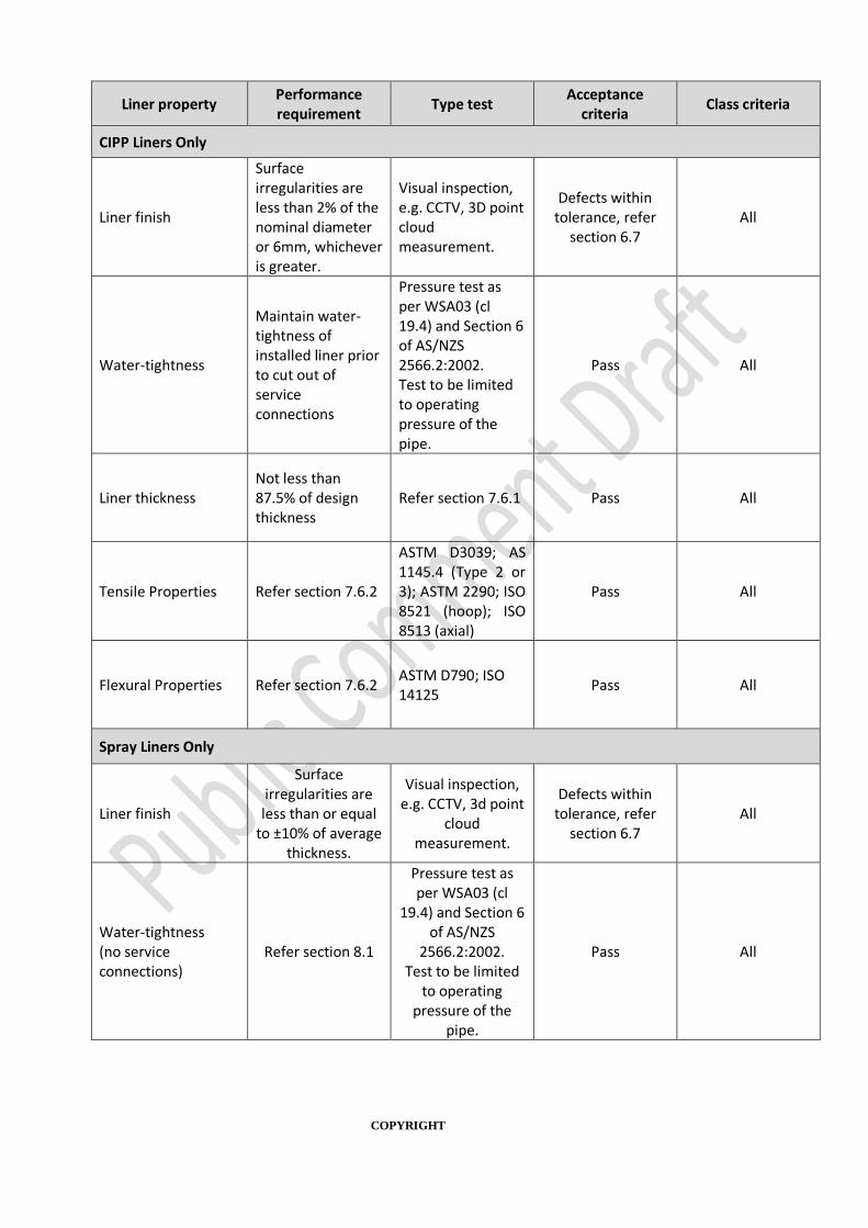
COPYRIGHT
Liner property Performance requirement
Type test Acceptance
criteria Class criteria
CIPP Liners Only
Liner finish
Surface irregularities are less than 2% of the nominal diameter or 6mm, whichever is greater.
Visual inspection, e.g. CCTV, 3D point cloud measurement.
Defects within tolerance, refer
section 6.7 All
Water-tightness
Maintain water-tightness of installed liner prior to cut out of service connections
Pressure test as per WSA03 (cl 19.4) and Section 6 of AS/NZS 2566.2:2002. Test to be limited to operating pressure of the pipe.
Pass All
Liner thickness Not less than 87.5% of design thickness
Refer section 7.6.1 Pass All
Tensile Properties Refer section 7.6.2
ASTM D3039; AS 1145.4 (Type 2 or 3); ASTM 2290; ISO 8521 (hoop); ISO 8513 (axial)
Pass All
Flexural Properties Refer section 7.6.2 ASTM D790; ISO 14125
Pass All
Spray Liners Only
Liner finish
Surface irregularities are less than or equal
to ±10% of average thickness.
Visual inspection, e.g. CCTV, 3d point
cloud measurement.
Defects within tolerance, refer
section 6.7 All
Water-tightness (no service connections)
Refer section 8.1
Pressure test as per WSA03 (cl
19.4) and Section 6 of AS/NZS
2566.2:2002. Test to be limited
to operating pressure of the
pipe.
Pass All

COPYRIGHT
Liner property Performance requirement
Type test Acceptance
criteria Class criteria
Liner thickness Varies by type.
Refer secion 7.4.1 All
Tensile Properties Refer section 7.5.2 ASTM D638 ISO 527-1 AS 1145.2
Pass All
Flexural Properties Refer section 7.5.2 D790
ISO 178 Pass All
Measurement of potential defects
Defects can cause isolated weak points in the installed liner that can impact its ability to withstand
service pressure in the long term.
Where a defect, or defects, are found, e.g. lumps, bubbles, inclusions, ripples, sags, runs,
stretchmarks, air holes and other film faults. Measurement of the defect may be required to
determine if it is outside acceptable tolerance. Accurate measurements cannot be taken using
standard CCTV equipment. A physical measurement, or use of a laser profiler with measurement
capability is recommended for liner defects. Spray liner thickness can be measured using robot
mounted ultrasound sensors, or an ultrasonic thickness sensor.
Rectification of defects
Where a defect is outside tolerance the section of lined pipe shall be removed and replaced in
accordance with Section 10 and the manufacturer’s instructions.
7.5 SPRAY LINERS
7.5.1 SPRAY LINER THICKNESS REQUIREMENTS
This section specifies what liner thickness measurements are required to be undertaken as well as liner
thickness requirements. Where applicable, measurements are taken from spray lining machine records,
from measurements at pipe ends, from cut-out sections, and by an automated ultrasonic device, as
detailed herein.
This section be read in conjunction with Section 1.7.
Spray Lining Machine Records
Where a spray lining machine is used, all the measurement records shall be used to assess compliance
with the following requirements.
Frequency: every lined pipe.
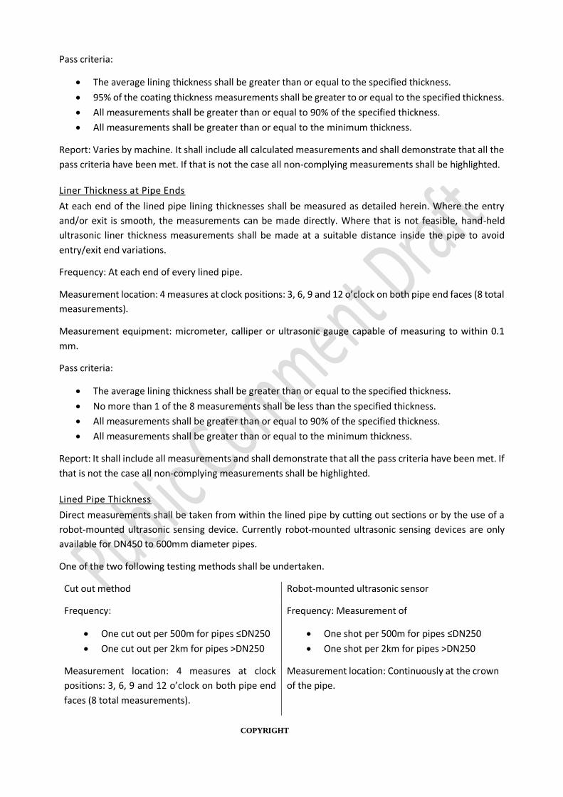
COPYRIGHT
Pass criteria:
• The average lining thickness shall be greater than or equal to the specified thickness.
• 95% of the coating thickness measurements shall be greater to or equal to the specified thickness.
• All measurements shall be greater than or equal to 90% of the specified thickness.
• All measurements shall be greater than or equal to the minimum thickness.
Report: Varies by machine. It shall include all calculated measurements and shall demonstrate that all the
pass criteria have been met. If that is not the case all non-complying measurements shall be highlighted.
Liner Thickness at Pipe Ends
At each end of the lined pipe lining thicknesses shall be measured as detailed herein. Where the entry
and/or exit is smooth, the measurements can be made directly. Where that is not feasible, hand-held
ultrasonic liner thickness measurements shall be made at a suitable distance inside the pipe to avoid
entry/exit end variations.
Frequency: At each end of every lined pipe.
Measurement location: 4 measures at clock positions: 3, 6, 9 and 12 o’clock on both pipe end faces (8 total
measurements).
Measurement equipment: micrometer, calliper or ultrasonic gauge capable of measuring to within 0.1
mm.
Pass criteria:
• The average lining thickness shall be greater than or equal to the specified thickness.
• No more than 1 of the 8 measurements shall be less than the specified thickness.
• All measurements shall be greater than or equal to 90% of the specified thickness.
• All measurements shall be greater than or equal to the minimum thickness.
Report: It shall include all measurements and shall demonstrate that all the pass criteria have been met. If
that is not the case all non-complying measurements shall be highlighted.
Lined Pipe Thickness
Direct measurements shall be taken from within the lined pipe by cutting out sections or by the use of a
robot-mounted ultrasonic sensing device. Currently robot-mounted ultrasonic sensing devices are only
available for DN450 to 600mm diameter pipes.
One of the two following testing methods shall be undertaken.
Cut out method Robot-mounted ultrasonic sensor
Frequency:
• One cut out per 500m for pipes ≤DN250
• One cut out per 2km for pipes >DN250
Frequency: Measurement of
• One shot per 500m for pipes ≤DN250
• One shot per 2km for pipes >DN250
Measurement location: 4 measures at clock
positions: 3, 6, 9 and 12 o’clock on both pipe end
faces (8 total measurements).
Measurement location: Continuously at the crown
of the pipe.

COPYRIGHT
Measurement equipment: micrometer, calliper or
ultrasonic gauge capable of measuring to within
0.1 mm.
Measurement equipment: robot-mounted
ultrasonic sensor
Pass criteria:
• The average lining thickness shall be
greater than or equal to the specified
thickness.
• No more than 1 of the 8 measurements
shall be less than the specified thickness.
• All measurements shall be greater than or
equal to 90% of the specified thickness.
• All measurements shall be greater than or
equal to the minimum thickness.
Pass criteria:
• The average lining thickness shall be
greater than or equal to the specified
thickness.
• 95% of the coating thickness
measurements shall be greater to or equal
to the specified thickness.
• All measurements shall be greater than or
equal to 90% of the specified thickness.
• All measurements shall be greater than or
equal to the minimum thickness.
Report requirements:
It shall include all measurements and shall demonstrate that all the pass criteria have been met. If that is
not the case all non-complying measurements shall be highlighted.
7.5.2 SPRAY LINER TENSILE AND FLEXURAL PROPERTIES
Installed spray liners shall be checked at a frequency of 1 test per 1km of liner installed to check
tensile properties or flexural properties are not less than 90% of declared properties.
Refer WSA XXX Water Industry Standard for polymeric spray lining materials used for the renovation
of drinking water pipes sections 5.2 and 5.3 for testing details.
7.6 CIPP LINERS
7.6.1 CIPP LINER THICKNESS
Direct measurements shall be taken of the liner thickness from a cutting out section of lined pipe.
Frequency: One cut out per 1km of lining, or as otherwise directed by the water agency.
Measurement location: 4 measures at clock positions: 3, 6, 9 and 12 o’clock on both pipe end faces
(8 total measurements).
Measurement equipment: micrometer, calliper, or other suitable measuring equipment capable of
measuring to within 0.1 mm.
Pass criteria: No measurements are less than 87.5% of design thickness.

COPYRIGHT
7.6.2 CIPP LINER TENSILE AND FLEXURAL PROPERTIES
Installed CIPP liners shall be checked at a frequency of 1 test per 1km of liner installed to check
tensile properties or flexural properties are not less than 90% of declared properties.
Refer WSA XXX Water Industry Standard for Cured-in-place pipes (CIPP) used for the renovation of
drinking water pipes sections 4.2 and 4.3 for testing details.
8 RETURN TO SERVICE OF NEWLY LINED PIPE
Prior to return of the newly lined pipe to service the following procedures shall be carried out.
8.1 HYDROSTATIC PRESSURE TESTING
The purpose of pressure testing lined pipes is to ensure that the installation is water-tight at
operational pressure.
Pressure testing is required for CIPP liners. Pressure testing shall be undertaken prior to
reconnection of service connections.
Pressure testing is recommended for spray liners (where no service connections present, or where
new service connections were installed as part of the works).
Pressure testing is not recommended for spray liners (where service connections are present and
have not been replaced as part of the works). This is because if the service lines are not replaced as
part of the works it can be very difficult to determine the location of the leak and who is responsible
for the repair.
Pressure testing of lined pipes and services connections is required and is to be conducted in
accordance with WSA03 – Water Supply Code of Australia.
It is recommended that test pressures for lined mains is reduced as per below.
Test Pressures
It is recommended that test pressures are limited to the operating pressure of the pipe. While intact,
the host pipe will continue to provide structural support to the liner (including for Class A liners).
Testing above the operating pressure is likely to cause damage to the host pipe. Damaging the host
pipe will reduce the overall life of the lined asset, as the liner will start to take the full load from
water pressure earlier. In addition, there is less risk of damaging services when testing to MAOP.
8.2 WATER QUALITY TESTING
Water quality testing shall be conducted in accordance the Water Agency’s requirements.
Where no requirements are specified the water quality testing shall be conducted in accordance
with WSA03 – Water Supply Code of Australia.
8.3 DISINFECTION AND WATER FLUSHING
Disinfection and flushing shall be conducted in accordance the Water Agency’s requirements.

COPYRIGHT
Where no requirements are specified disinfection and flushing shall be conducted in accordance
with WSA03 – Water Supply Code of Australia.
9 LINED ASSET AS-CONSTRUCTED INFORMATION
The applicator shall record the following as constructed in formation and submit it at the conclusion
of lining to the Water Agency:
• A plan of the works indicating the lined pipe(s), extent of lining works, location of any repair
works, location of any new appurtenances.
• Liner type, i.e. CIPP or Spray Liner.
• Liner class.
• Liner thickness (mm).
• Nominal diameter.
• CCTV where applicable.
• Inspection and Test Plans.
The information shall conform to the water agency’s as-constructed information data requirements.
10 LINER MAINTENANCE Over the course of the life of the liner, damage to the liners may need to be repaired and connections for
new services installed.
Suppliers are required to submit documentation detailing the requirements for liner maintenance
and repair as part of the product appraisal process. This information should be consulted when
undertaking repairs, as individual requirements vary based on the lining system.
10.1 REPAIRS TO NEWLY INSTALLED LINERS
Where the damage is localised and has the potential to create a local leak event, rather than a structural
failure of the liner, the repair can be undertaken using standard pipe repair techniques. The damaged
section of the liner and pipe is cut out and a small section of pipe is installed with an end seal at each end.
The requirements from section 6.9 Host Pipe Connections (End Seals) apply to lined pipe repairs.
10.2 MAINTENANCE LINING
In general, where existing linings are mostly sound, it may be possible to patch repair any exposed
substrate and feathered areas with the lining system specified.
Where planning full removal of the existing liner and reinstatement of a new lining system, the same
installation methodology shall be followed as for a new liner.

COPYRIGHT
Where planning to line over the top of an existing liner (without removal) the sup plier should be
consulted to ensure the compatibility of the lining systems.
10.3 NEW SERVICE CONNECTIONS
During the life of the lined pipe new service connections may need to be installed. Connection of
new tappings shall be made into the liner without damaging the liner, or causing the liner to pull
away from the host pipe. The directions of the product supplier shall be followed to ensure a water-
tight connection and prevent the introduction of a flow path for water between the liner and the
host pipe.
The lining supplier shall detail OHS requirements, if any.
Fittings required for new service connections shall comply with the requirements of the relevant
Water Industry Standard.
Standard methods using pipe saddles or threaded fittings may not be appropriate (without
modification), as these methods can provide a connection to the host pipe without connecting
through to the liner. Where the service connection does not connect throug h to the liner it may
provide a water path between the host pipe and the liner due to the limited bond between the two
materials.
In general, the tapping shall use a cutting tool to ensure a clean cut, rather than a punching tool,
such as a drill bit. For pipes with cement mortar lining, the tapping shall be connected to the liner
mechanically to avoid water ingress into the CML. Refer to Achieving Water-tightness in Section 6.8
for additional details.

COPYRIGHT
11 APPENDIX 1: STRUCTURAL CLASSIFICATION OF LINERS
Piping systems used for the renovation of pressure pipelines are classified in ISO 11295 in
accordance with their structural performance as follows.
CLASS A
• Can survive internally or externally induced failure of the host pipe.
• The long-term pressure rating is equal to or greater than the maximum allowable operating
pressure of the renovated pipeline.
• The liner has sufficient inherent ring stiffness to be self-supporting when depressurised.
• Is capable of spanning gaps and holes long-term at the maximum allowable operating
pressure.
• Provides an internal barrier to the corrosion, abrasion and/or tuberculation / scaling of the
host pipe and to the contamination of the pipe contents by the host pipe. Generally it also
reduces the surface roughness for improved hydraulic performance.
CLASS B
• The liner has sufficient inherent ring stiffness to be self-supporting when depressurised.
• Is capable of spanning gaps and holes long-term at the maximum allowable operating
pressure.
• NOTE: The liner becomes sufficiently close fit during installation or during initial operation
for transfer of the internal pressure stress to the host pipe.
• Provides an internal barrier to the corrosion, abrasion and/or tuberculation / scaling of the
host pipe and to the contamination of the pipe contents by the host pipe. Generally it also
reduces the surface roughness for improved hydraulic performance.
CLASS C
The liner relies on adhesion to the host pipe to be self-supporting when depressurised.
Is capable of spanning gaps and holes long-term at the maximum allowable operating pressure.
NOTE: The liner becomes sufficiently close fit during installation or during initial operation for
transfer of the internal pressure stress to the host pipe.

COPYRIGHT
Provides an internal barrier to the corrosion, abrasion and/or tuberculation / scaling of the host
pipe and to the contamination of the pipe contents by the host pipe. Generally it also reduces the
surface roughness for improved hydraulic performance.
CLASS D
• The liner relies on adhesion to the host pipe to be self-supporting when depressurised.
• Provides an internal barrier to the corrosion, abrasion and/or tuberculation / scaling of the
host pipe and to the contamination of the pipe contents by the host pipe. Generally it also
reduces the surface roughness for improved hydraulic performance.

46 WSA 201—2017-2.1
COPYRIGHT
12 APPENDIX 2 EXAMPLES OF INSPECTION AND TEST PLANS
CIPP Lining Inspection and Test Plan (Sample)
Date
Project
Location
Client
No. Activity Inspection and Test
Activity Frequency
Relevant Standard
Pass Criteria Responsible
Party
Hold point or
Witness Point
Record Date
completed Sign-off Notes
1 Planning and design
Proposed lining system checked against pipe characteristics and Water Agency service life requirements.
Once per shot
Pipe evaluation platform
Meets Water Agency requirements
Applicator H
2
Assess Water Main: Review for go / no-go conditions, e.g. pipe collapse or large internal diameter changes.
CCTV Once per shot
WSA05 - Conduit Inspection Reporting Code
Absence of no-go conditions.
Applicator H May be completed following surface cleaning (particularly if main ID restricted with corrosion products)
3 Surface Preparation
3A Record original surface CCTV Once per shot
WSA05 - Conduit Inspection Reporting Code
NA Applicator NA CCTV can be combined with "Assess Water Main"
3B Record method(s) used Record only Once per shot
Manual for selection and application of cured-in-place pipe (CIPP) and spray liners for use in water pipe
NA Applicator NA
COPYRIGHT
No. Activity Inspection and Test
Activity Frequency
Relevant Standard
Pass Criteria Responsible
Party
Hold point or
Witness Point
Record Date
completed Sign-off Notes
3C Record prepared surface CCTV Once per shot
WSA05 -
Conduit
Inspection
Reporting
Code;
Manual for
selection and
application of
cured-in-place
pipe (CIPP) and
spray liners for
use in water
pipe; and
WSA XXX
Water Industry
Standard for
Cured-in-place
pipes (CIPP)
used for the
renovation of
drinking water
pipes.
Requirements for lining system met.
Applicator H
4 Transportation and storage
4A Resin
Record: Container #, Manufacturer's label, Batch No., Product Code, Mix Ratio Required, Expiry Date, Unopened and Seals Intact, Storage Requirements, Storage Requirements Met During Transport, Storage Requirements Met on Site
For all items received
WSA XXX
Water Industry
Standard for
Cured-in-place
pipes (CIPP)
used for the
renovation of
drinking water
pipes and
Manufacturer
Information
Requirements for lining system met.
Applicator H Refer transportation and storage record table below.

COPYRIGHT
No. Activity Inspection and Test
Activity Frequency
Relevant Standard
Pass Criteria Responsible
Party
Hold point or
Witness Point
Record Date
completed Sign-off Notes
4B CIPP lining tube Inspect for correct size and any defects, e.g. holes, tears.
For all items received
WSA XXX
Water Industry
Standard for
Cured-in-place
pipes (CIPP)
used for the
renovation of
drinking water
pipes and
Manufacturer
Information
Size correct and free of defects
Applicator H
5 Pre-lining checks
5.1
Record ambient conditions: Ambient temperature Dewpoint Relative humidity
Record and check go/no-go condition met
For every shot
Manufacturer information
Pass/Fail Applicator H
5A Pull through liners
5A.1 Lining tube max. acceptable pulling force
Record only Once per shot
Manufacturer information
Applicator NA
5A.2 Pulling force capacity Record of equipment capacity
Once per shot
Equipment information
Applicator NA
5A.3 Pulling force restriction Record of equipment settings, e.g. on load limiting device.
Once per shot
NA
Force restriction less than or equal to lining tube max. acceptable pulling force
Applicator H
6 Mixing (resins)
6A Date and time of mix Record only For every mix NA NA Applicator NA
6B Mix ratio used Record only For every mix NA NA Applicator NA
6C Mix quality/time Record only For every mix NA NA Applicator NA

COPYRIGHT
No. Activity Inspection and Test
Activity Frequency
Relevant Standard
Pass Criteria Responsible
Party
Hold point or
Witness Point
Record Date
completed Sign-off Notes
6D Pot life Record only For every mix Manufacturer information
NA Applicator NA
7 Lining
7A Surface
Check surface requirements met, e.g. no standing water, moisture level, etc.
Immediate prior to lining. Once per shot.
WSA XXX
Water Industry
Standard for
Cured-in-place
pipes (CIPP)
used for the
renovation of
drinking water
pipes and
Manufacturer
information.
All conditions within acceptable limits.
Applicator H
7B Equipment Check suitable for product type and size of application
Once per shot
Manufacturer information
Pass/Fail Applicator NA
7C Liner Stretching
Monitor pulling/inversion speed
For every shot
Manufacturer information
Pass/Fail Applicator H
7D Required Curing Time Record only Once per shot
WSA XXX
Water Industry
Standard for
Cured-in-place
pipes (CIPP)
used for the
renovation of
drinking water
pipes and
Manufacturer
information.
NA Applicator NA

COPYRIGHT
No. Activity Inspection and Test
Activity Frequency
Relevant Standard
Pass Criteria Responsible
Party
Hold point or
Witness Point
Record Date
completed Sign-off Notes
7E Actual Curing Time Record only Once per shot
WSA XXX
Water Industry
Standard for
Cured-in-place
pipes (CIPP)
used for the
renovation of
drinking water
pipes and
Manufacturer
information.
NA Applicator H
7F Curing Temperature Record only For every shot
Manufacturer
information Pass/Fail Applicator NA
7G Curing Pressure Record only For every shot
Manufacturer
information Pass/Fail Applicator NA
7H Roller set and check times (for resin distribution)
Record only Applicator nominated
Manual for selection and application of cured-in-place pipe (CIPP) and spray liners for use in water pipe
Setting is as per requirement
Applicator NA Rollers are used to ensure an even spread of resin along the carrier material.
7I Water-tightness Check
Maintain water-tightness of installed liner prior to cut out of service connections
For every shot
Pressure test as per WSA03 (cl 19.4) and Section 6 of AS/NZS 2566.2:2002. Test to be limited to operating
As per standard
Applicator W

COPYRIGHT
No. Activity Inspection and Test
Activity Frequency
Relevant Standard
Pass Criteria Responsible
Party
Hold point or
Witness Point
Record Date
completed Sign-off Notes
pressure of the pipe.
8 Service Reinstatement
8A Service cut out or replaced CCTV inspection. For every service
Manual for selection and application of cured-in-place pipe (CIPP) and spray liners for use in water pipe
90% open, smooth cut edge.
Applicator W
8B Check flow at property Check property tap for flow.
For every service
NA Pass/Fail Applicator NA
9 Post lining checks
9A Visual defects check CCTV inspection Once per shot
Record only Pass/Fail Applicator W Can be combined with property service CCTV
9B Quantify size of surface irregularities
Measurement, e.g. 3D point cloud (non-destructive), or calliper measurement of sample (destructive)
All defects
WSA XXX
Water Industry
Standard for
Cured-in-place
pipes (CIPP)
used for the
renovation of
drinking water
pipes and
Manufacturer
information.
All defects within tolerance. Where outside tolerance refer to water agency
Applicator W

COPYRIGHT
No. Activity Inspection and Test
Activity Frequency
Relevant Standard
Pass Criteria Responsible
Party
Hold point or
Witness Point
Record Date
completed Sign-off Notes
9C Water Quality Check Bacteriological levels below required standards
As per water agency requirements
WSA 03-2011-
3.1 Appendix I
Pass / Fail
Applicator H
9D Liner thickness Measured as per section 7.6.1
1 per 1km lining This manual
No measurements are less than 87.5% of design thickness
Applicator H
9E Tensile or flexural properties
Measured as per section 7.6.2
1 per 1km lining This manual
not less than 90% of declared properties
Applicator H

COPYRIGHT
Sample ITP for Transport and Storage of Liner Component Materials
Resin
Container # Manufacturer's label
Batch No. Product Code
Mix Ratio Required
Expiry Date Unopened and Seals
Intact
Storage Requirements
Storage Requirements Met During Transport
Storage Requirements Met on Site
Notes

COPYRIGHT
Spray Lining Inspection and Test Plan (Sample)
Date
Project
Location
Client
No. Activity Inspection and Test
Activity Frequency
Relevant Standard
Pass Criteria Responsible
Party
Hold point or
Witness Point
Record Date
completed Sign-off Notes
1 Planning and design
Proposed lining system checked against pipe characteristics and Water Agency service life requirements.
Once per shot
[Pipe evaluation platform]
Meets water Agency requirements
Applicator H
2
Assess Water Main: Review for go / no-go conditions, e.g. pipe collapse or large internal diameter changes.
CCTV Once per shot
WSA05 - Conduit Inspection Reporting Code; and Manual for selection and application of cured-in-place pipe (CIPP) and spray liners for use in water pipe
Absence of no-go conditions.
Applicator H May be completed following surface cleaning (particularly if main ID restricted with corrosion products)
3 Surface Preparation
3A Record original surface CCTV Once per shot
WSA05 - Conduit Inspection Reporting Code
NA Applicator NA CCTV can be combined with "Assess Water Main"
3B Record method(s) used Record only Once per shot
Manual for selection and application of cured-in-place pipe (CIPP) and spray liners for use in water pipe
NA Applicator NA

COPYRIGHT
No. Activity Inspection and Test
Activity Frequency
Relevant Standard
Pass Criteria Responsible
Party
Hold point or
Witness Point
Record Date
completed Sign-off Notes
3C Record prepared surface CCTV Once per shot
WSA05 -
Conduit
Inspection
Reporting Code;
Manual for
selection and
application of
cured-in-place
pipe (CIPP) and
spray liners for
use in water
pipe and
WSA XXX Water
Industry
Standard for
polymeric spray
lining materials
used for the
renovation of
drinking water
pipes.
Requirements for lining system met.
Applicator H
4 Transportation and storage
4A Resin
Record: Container #, Manufacturer's label, Batch No., Product Code, Mix Ratio Required, Expiry Date, Unopened and Seals Intact, Storage Requirements, Storage Requirements Met During Transport, Storage Requirements Met on Site
For all items received
WSA XXX Water
Industry
Standard for
polymeric spray
lining materials
used for the
renovation of
drinking water
pipes and
Manufacturer
Information
Requirements for lining system met.
Applicator H Refer transportation and storage record table below.
5 Pre-lining checks

COPYRIGHT
No. Activity Inspection and Test
Activity Frequency
Relevant Standard
Pass Criteria Responsible
Party
Hold point or
Witness Point
Record Date
completed Sign-off Notes
5A
Record ambient conditions: Ambient temperature Dewpoint Relative humidity
Record and check go/no-go condition met
For every shot
Manufacturer information
Pass/Fail Applicator H
6 Mixing (resins)
6A Date and time of mix Record only For every mix NA NA Applicator NA
6B Mix ratio used Record only For every mix NA NA Applicator NA
6C Mix quality/time Record only For every mix NA NA Applicator NA
6D Pot life Record only For every mix NA NA Applicator NA
7 Lining
7A Surface
Check surface requirements met, e.g. no standing water, moisture level, etc.
Immediate prior to lining. Once per shot.
WSA XXX Water
Industry
Standard for
polymeric spray
lining materials
used for the
renovation of
drinking water
pipes and
Manufacturer
information.
All conditions within acceptable limits.
Applicator H
7B Equipment Check suitable for product type and size of application
Once per shot
Manufacturer information.
Pass/fail Applicator H
7C Required Recoat Time Record only Once per coating
WSA XXX Water
Industry
Standard for
polymeric spray
lining materials
used for the
renovation of
Drying times met
Applicator NA
COPYRIGHT
No. Activity Inspection and Test
Activity Frequency
Relevant Standard
Pass Criteria Responsible
Party
Hold point or
Witness Point
Record Date
completed Sign-off Notes
drinking water
pipes and
Manufacturer
information.
7D Actual Recoat Time Record only Once per coating
WSA XXX Water
Industry
Standard for
polymeric spray
lining materials
used for the
renovation of
drinking water
pipes and
Manufacturer
information.
Drying times met
Applicator NA
7E Required final curing time Record only Once per shot
Manual for selection and application of cured-in-place pipe (CIPP) and spray liners for use in water pipe
Drying times met
Applicator NA Rollers are used to ensure an even spread of resin along the carrier material.
7F Actual final curing time Record only Once per shot
WSA XXX Water
Industry
Standard for
polymeric spray
lining materials
used for the
renovation of
drinking water
pipes and
Manufacturer
information.
Drying times met
Applicator H
COPYRIGHT
No. Activity Inspection and Test
Activity Frequency
Relevant Standard
Pass Criteria Responsible
Party
Hold point or
Witness Point
Record Date
completed Sign-off Notes
8 Service Reinstatement
8A All connections are clear CCTV inspection. For every service
Manual for selection and application of cured-in-place pipe (CIPP) and spray liners for use in water pipe
90% open, smooth edge.
Applicator W
8B Check flow at property Check property tap for flow.
For every service
NA Pass / Fail Applicator H
9 Post lining checks
9A Visual defects check CCTV inspection Once per shot
Manual for selection and application of cured-in-place pipe (CIPP) and spray liners for use in water pipe Section 6.7
Present / Not Present
Applicator NA Can be combined with property service CCTV
9B Quantify defect size
Measurement, e.g. 3D point cloud (non-destructive), or calliper measurement of sample (destructive)
All defects
WSA XXX Water
Industry
Standard for
polymeric spray
lining materials
used for the
renovation of
drinking water
pipes and
Manufacturer
information.
All defects within tolerance. Where outside tolerance refer to water agency
Applicator H

COPYRIGHT
No. Activity Inspection and Test
Activity Frequency
Relevant Standard
Pass Criteria Responsible
Party
Hold point or
Witness Point
Record Date
completed Sign-off Notes
9C Liner thickness Measure liner thickness as per section 7.5.1
See section 7.5.1 This manual
See section 7.5.1
Applicator H
9D Water Quality Check Bacteriological levels below required standards
As per water agency requirements
WSA 03-2011-
3.1 Appendix I
Pass / Fail
Applicator H
9E Water-tightness check (where no service connections)
Maintain water-tightness at operational pressure
For every shot
Pressure test as
per WSA03 (cl
19.4) and
Section 6 of
AS/NZS
2566.2:2002.
Test to be
limited to
operating
pressure of the
pipe.
Pass / Fail
Applicator W
9F Tensile or Flexural Properties
Measured as per section 7.5.2
1 per 1km lining This manual
not less than 90% of declared properties
Applicator H

60 WSA 201—2017-2.1
COPYRIGHT