manual for owners and skippers -...
TRANSCRIPT

Manual for owners and skippers
Sailing yacht „BAVARIA 40vision“
Bavaria Yachtbau GmbH •••• Bavariastr. 1 •••• D – 97232 Giebelstadt Tel.: +49 (0) 9334 942 – 0; Fax: +49 (0)9334 942 – 116
E-Mail : [email protected]

Sailing yacht “Bavaria 40vision” Bavaria Yachtbau GmbH
2 of 43
Introduction ................................................................................................................................................................................. 4
Certification ................................................................................................................................................................................. 5
Identification ............................................................................................................................................................................... 5
Builder’s plate ............................................................................................................................................................................. 5
Warnings ..................................................................................................................................................................................... 6
Declaration of Conformity .......................................................................................................................................................... 7
1. Description of the yacht ........................................................................................................................................................ 11
1.1 Main particulars ............................................................................................................................................................... 11 1.1.1 Principal dimensions ................................................................................................................................................ 11 1.1.2 Displacement and weights ........................................................................................................................................ 11 1.1.3 Motorization ............................................................................................................................................................. 11 1.1.4 Electrical installation ................................................................................................................................................ 11 1.1.5. Tank capacities ........................................................................................................................................................ 11 1.1.6. Fixing points for cranes, resting-points for slipping and transport .......................................................................... 11
1.2 General arrangement ....................................................................................................................................................... 12 1.2.1 Rigging plan ............................................................................................................................................................. 12 1.2.2 Deck arrangement..................................................................................................................................................... 13 1.2.3. Accommodation plan .............................................................................................................................................. 15
1.3 Drive systems .................................................................................................................................................................. 16 1.3.1 Sails .......................................................................................................................................................................... 16
1.3.2 Rigging ..................................................................................................................................................................... 16 1.3.3 Motorising, engine room, gear, and propeller .......................................................................................................... 16
2. Installations and circuits ........................................................................................................................................................ 18
2.1 Tanks and piping - water ................................................................................................................................................. 18 2.1.1 Fresh water, drinking water –cold ............................................................................................................................ 18 2.1.2 Sea-water circulation ................................................................................................................................................ 18 2.1.3 WC –installation: see enclosed directions for use .................................................................................................... 19
2.2 Tanks and piping - fuel .................................................................................................................................................... 20 2.3 Steering gear .................................................................................................................................................................... 20
2.3.1 Description of the system ......................................................................................................................................... 20 2.3.2 Rudder blade and rudder bearings ............................................................................................................................ 20
2.4. Bilge pumps, bilge pipes ................................................................................................................................................ 22 2.4.1 Description of the pumping arrangement ................................................................................................................. 22
2.5 The electric installation ................................................................................................................................................... 23 2.5.1 The AC-installation (230 Volt) ................................................................................................................................ 23 2.5.2 The DC–board net (12 Volt)..................................................................................................................................... 23 2.5.3 Operating the installation and specific features ........................................................................................................ 23 2.5.4 Important warnings on the DC-installation (12 Volt) ............................................................................................... 24
2.5.5 Important warnings on the AC-installation (230 Volt/ 115 Volt)............................................................................. 24
2.5.6.1 Distribution of electric devices (3 Cabins) ............................................................................................................ 25 2.5.6.2 Distribution of electric devices (2 Cabins) ............................................................................................................ 27 2.5.7 Wiring plans ............................................................................................................................................................. 29 2.5.8 Distribution plans ..................................................................................................................................................... 29 2.5.9 AC-distribution ......................................................................................................................................................... 29
2.6 L.P.G. installation ............................................................................................................................................................ 29 2.6.1 The components ....................................................................................................................................................... 29 2.6.2 Operation .................................................................................................................................................................. 30
2.7 Fire protection ................................................................................................................................................................. 30 2.8 Anchor (option) ............................................................................................................................................................... 32 2.9 Engine cooling system ..................................................................................................................................................... 32 2.10 Exhaust gas system ........................................................................................................................................................ 32 2.11 Ventilation/Airing ......................................................................................................................................................... 33 2.12 Board ducts, sea water valves ........................................................................................................................................ 33 2.13 Generator (Option for 44vision, 50vision, 50 Cruiser) .................................................................................................. 34
3. Environmenta l pro tect ion ........................................................................................................................................... 35
3.1 Fuel and oil ...................................................................................................................................................................... 35
3.2 Waste ............................................................................................................................................................................... 35

Sailing yacht “Bavaria 40vision” Bavaria Yachtbau GmbH
3 of 43
3.3 Sound ............................................................................................................................................................................... 35
3.4 Swell ................................................................................................................................................................................ 35
3.5 Exhaust gas ...................................................................................................................................................................... 35
3.6 Antifouling coatings ........................................................................................................................................................ 35 3.7 Varnish removers ............................................................................................................................................................ 35
4. Maintenance ..................................................................................................................................................................... 36
4.1 Maintenance, cleaning ..................................................................................................................................................... 36 4.2 Wearing- and spare parts ................................................................................................................................................. 37 4.3 Repair work ..................................................................................................................................................................... 37 4.4 Winter storage ................................................................................................................................................................. 37
5. F inal remarks and notes .............................................................................................................................................. 39
6. List o f manuals suppl ied ............................................................................................................................................. 40

Sailing yacht “Bavaria 40vision” Bavaria Yachtbau GmbH
4 of 43
Introduction This manual will help you to handle your yacht safely and with pleasure. Apart from information about the yacht itself and installed or additionally supplied fittings the manual also contains information on operation and maintenance. Please familiarise yourself with everything before you go on your first voyage. If this is your first yacht or if you are not really familiar with the special characteristics of a motor yacht please make sure you get proper training before you put it into operation. Do not hesitate to contact the dealer or our shipyard for information about further training possibilities. As the scope of supply depends on the order, the equipment of your yacht can deviate with some descriptions and illustrations. In order to be able to adapt our yachts to the constantly progressing technical standard, we must reserve ourselves changes in form, equipment and technology. For these reasons no requirements can be derived from all data, illustrations and descriptions in this manual.
PLEASE KEEP THIS MANUAL IN A SAFE PLACE
AND HAND IT OVER TO THE NEW OWNER IF YOU SELL THE Y ACHT.
BAVARIA would like to welcome you to the circle of BAVARIA owners and would like to thank you for placing your confidence in our products by acquiring this yacht. Your contract partner and the management and staff of Bavaria Yachtbau GmbH hope you will enjoy your new yacht.
Bon voyage, fair winds and fine weather. BAVARIA Yachtbau GmbH Management K. Hammen

Sailing yacht “Bavaria 40vision” Bavaria Yachtbau GmbH
5 of 43
Category of design
Following the European Recreational Craft Directive each boat has to be classified according to a category of design. All sailing yachts of BAVARIA belong to the category of design A, Designed for extended voyages where conditions may exceed wind force 8 (Beaufort scale) and significant wave heights of 4 m and above but excluding abnormal conditions, and vessels largely self-sufficient. Certification Actually the EC Directive intends for yachts of this size the certification module B. IMCI (International Marine Certification Institute) located in Bruxelles was put into charge as a notified body (see: Declaration of Conformity). Identification The hull identification was formed into the transom on starboard side. This is a unique sequence of digits and letters. Builder’s plate The builder’s plate on the front wall of the cockpit is a demand of the Directive because certain information are required which will be explained in the following. Explanations - Category of design A : Ocean
- Max. =10 : Maximum number of persons recommended by the manufacturer if the yacht
is situated in the sea area corresponding to the category of design. The number of crew can be increased under consideration of the maximum additional loading capacity if the yacht is on a voyage in non-ocean areas.
-Max + = 1200 kg : Maximum additional loading including 10 persons, stores, provisions and
personal equipment (excluding tank capacities). - CE 0609 : CE marking which indicates the conformity of the yacht with all provisions of
the Directive. The sequence of digits is the code number of the certifying body, in this case the IMCI (International Marine Certification Institute) (see: Declaration of Conformity).

Sailing yacht “Bavaria 40vision” Bavaria Yachtbau GmbH
6 of 43
Warnings Many chapters of this manual will support a trouble free operation, maintenance or draw your attention to signs of dangers. To find them more easily they are especially marked (in boxes or in bold). We advise you to study them carefully although the experienced skipper might be quite familiar with many of them. The following chapters contain such warnings/notes or other important information for operating the yacht. Always consider the maritime duty to exercise diligence! Danger
Means, that an extreme real hazard which will lead to the death or too irreparable injuries with great probability exists if no adequate precautions are found.
Warning
Means, that a hazard which can lead to injuries or death exists if no adequate precautions are found.
Caution
Means that a memory of safety measures or the attention judges on handling, which can be unsure or lead to personal injuries or to harm of the vessel or from components.
Security advice Attention!
From wind force 6 the hatch in the cab entrance is to be closed. Attention!
Starting from wind force 6 the cab windows in the cockpit are to be closed. Attention!
Make yourself and your crew familiar with the bath platform. It makes the re-entrance possible!

Sailing yacht “Bavaria 40vision” Bavaria Yachtbau GmbH
9 of 43

Sailing yacht “Bavaria 40vision” Bavaria Yachtbau GmbH
10 of 43
Sailing yacht “Bavaria 40vision” Bavaria Yachtbau GmbH
11 of 43
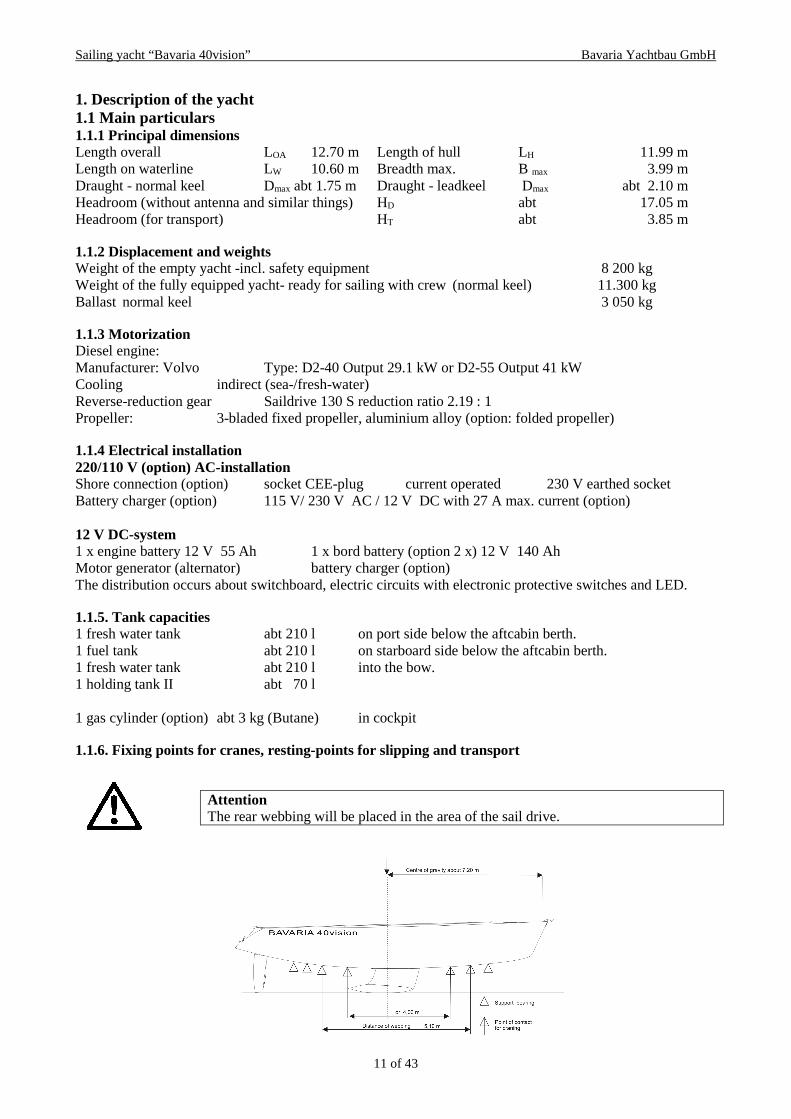
1. Description of the yacht 1.1 Main particulars 1.1.1 Principal dimensions Length overall LOA 12.70 m Length of hull LH 11.99 m Length on waterline LW 10.60 m Breadth max. B max 3.99 m Draught - normal keel Dmax abt 1.75 m Draught - leadkeel Dmax abt 2.10 m Headroom (without antenna and similar things) HD abt 17.05 m Headroom (for transport) HT abt 3.85 m 1.1.2 Displacement and weights Weight of the empty yacht -incl. safety equipment 8 200 kg Weight of the fully equipped yacht- ready for sailing with crew (normal keel) 11.300 kg Ballast normal keel 3 050 kg 1.1.3 Motorization Diesel engine: Manufacturer: Volvo Type: D2-40 Output 29.1 kW or D2-55 Output 41 kW Cooling indirect (sea-/fresh-water) Reverse-reduction gear Saildrive 130 S reduction ratio 2.19 : 1 Propeller: 3-bladed fixed propeller, aluminium alloy (option: folded propeller) 1.1.4 Electrical installation 220/110 V (option) AC-installation Shore connection (option) socket CEE-plug current operated 230 V earthed socket Battery charger (option) 115 V/ 230 V AC / 12 V DC with 27 A max. current (option) 12 V DC-system 1 x engine battery 12 V 55 Ah 1 x bord battery (option 2 x) 12 V 140 Ah Motor generator (alternator) battery charger (option) The distribution occurs about switchboard, electric circuits with electronic protective switches and LED. 1.1.5. Tank capacities 1 fresh water tank abt 210 l on port side below the aftcabin berth. 1 fuel tank abt 210 l on starboard side below the aftcabin berth. 1 fresh water tank abt 210 l into the bow. 1 holding tank II abt 70 l 1 gas cylinder (option) abt 3 kg (Butane) in cockpit 1.1.6. Fixing points for cranes, resting-points for slipping and transport Attention
The rear webbing will be placed in the area of the sail drive.

Sailing yacht “Bavaria 40vision” Bavaria Yachtbau GmbH
12 of 43
1.2 General arrangement 1.2.1 Rigging plan
Reference The valid measuring of the foresail reefing gear are on the enclosure note at the carton of the Furlex-foresail reefing gear.
Caution!
Do not enter the front salon windows and the deck hatch. Slip hazard!
Minimum operating condition (mMOC)
Loaded displacement condition (mLDM )
STIX 32,8 37,7 Angle of vanishing (degrees)
125° 125

Sailing yacht “Bavaria 40vision” Bavaria Yachtbau GmbH
13 of 43
1.2.2 Deck arrangement

Sailing yacht “Bavaria 40vision” Bavaria Yachtbau GmbH
14 of 43
1 Bow navigation light Zweifarbenleuchte 2 Bow fitting Bugbeschlag 3 Bow pulpit Bugkorb 4 Guard lines Relingsdurchzüge 5 Water inlet Wasser Einfüllstutzen 6 Anchor chain bail Ankerkasten 7 Mooring cleats Belegklampe 8 Stanchion Relingstütze 9 Foot stop Fussreling 11 Stanchion base Relingfuss 12 Hooking point Deckauge 13 Fuel inlet Diesel Einfüllstutzen 14 Op. hatch Vorschiffsluke 15 Op. hatch Vorschiffsluke 16 Portlight Fenster 17 Spinnaker winch Spinnaker Winde 18 Main shrows + aft kiwers cgk Wantenpütting 19 Electric windlass Elektrische Ankerwinde 20 Port light Fenster 21 Deck organizer Umlenkblöcke 22 Genoa track Genoaschiene 23 Genoa track car Genoaschlitten 24 Main sheet track Grossschotschlitten 25 Main sheet track car Grossschotschiene 26 Front end stop (g. track) Schienenendstück 27 Aft end stop (g. track) Schienenendstück mit Umlenkblöken 28 Endstops main sheet track Schienenendkappe 29 Genoa winch Genuawinde 30 Stopper Stopper 31 Winch Fallwinde 32 Ventilator Decklüfter 33 Cable penetration Kabeldurchführung 34 Sliding hatch Schiebeluke 35 Washboard Steckschott 36 Aft port pushpit Heckkorb links 37 Aft starboard pushpit Heckkorb rechts 38 Backstay chain plate Achterstagpütting 39 Aft pushpit life line Strecktau mit Pelikanhaken 40 Boarding ladder Badeleiter 42 Stern light Hecklaterne 43 Hand operated bilge pump Handlenzpumpe 44 Shore socket 230 V Steckdose 230 V 45 Engine ventilation inlet Belüftungsroste 47 Tiller Pinne 49 Steering wheel Steuerrad 50 Cockpit port light Cockpit Portlight 51 Foot block with lock off Liegender Block mit Stopper 54 Winch handle pocket Halter für Windenkurbel 55 Engine panel Motorinstrumententafel

Sailing yacht “Bavaria 40vision” Bavaria Yachtbau GmbH
15 of 43
1.2.3. Accommodation plan
1 Steering gear Ruderanlage 2 Double berth Doppelbett 3 Shelf Schrank 4 Companion way / engine room Niedergang / Motorraum 5 Head WC 6 Shower Dusche 7 Cooling Kühlbox 8 Gas cooker with oven Gasbackofen 9 Sink Spüle 10 Hanging locker Hängeschrank 11 Double berth Doppelbett 12 Chain locker Ankerkasten 13 Shelf Schrank 14 Hanging locker Hängeschrank 15 Book locker Bücherschapp 16 Saloon table Salontisch 17 Seating Sitzgruppe 18 Chart table Kartentisch 19 Electrical switch panel Elektrische Schalttafel

Sailing yacht “Bavaria 40vision” Bavaria Yachtbau GmbH
16 of 43
1.3 Drive systems 1.3.1 Sails The SY Bavaria 40vision is equipped with the following standard sails: Main sail - fully-battened abt 39,60 sqm Main sail “ - mast reefing gear abt 34,40 sqm Furling Genoa abt 48,50 sqm 1.3.2 Rigging Mast LM- Profile, without taper; – 18 deg. double spreaders , angular; - 2 halyards, topping- and boom lifts, Tipping line and fittings. Boom - LM-Profile; - clew outhaul; - 2 reefing lines; - eye for mainsheet; - eye for tipping line. Standing rigging (made of 1x19–lace, material 4401), consisting of: forestay with excessive footage (headsail reef system)
1 x upper shroud 2 x
permanent backstay with bridle 1 x lower shroud 2 x permanent backstay tackle 1 x intermediate shroud 2 x Running Rigging Inside the mast: Option: - Main halyard - Spinnaker halyard (attached) - Genoa halyard - Spinnaker uphaul - Boom lift - Spinnaker downhaul Inside the boom: 2 reef lacings (battened sail); 1 foot jig
Complementing we refer onto the enclosed trim instructions of the manufacturer.
1.3.3 Motorising, engine room, gear, and propeller This yacht is equipped with a inboard diesel engine with a sail-drive gear and a fixed propeller (option: folded propeller). The engine room is separated from living quarters by plywood-bulkheads covered with sound-insulating material. An access is possible through: - a shutter below the companion way, - detachable bulkhead in the aft cabin beside the engine room Cooling-water supply to the engine is realised via the sail drive-gear.
Caution Before of every sail:
- Test strings, cordage, lanyards and split pins. - Safeguard the split pins through adhesive tape or bending. - Transpose deformed or damaged bolts.

Sailing yacht “Bavaria 40vision” Bavaria Yachtbau GmbH
17 of 43
Engine plant
1 Engine Volvo Motor Volvo 2 Engine exhaust system Motorabgassystem 3 Exhaust water lock Abgaswassersammler 4 Engine fuel intake Kraftstoffeinfüllstutzen 5 Feed back fuel Kraftstoffrückführleitung 6 Fuel tank filling hose Kraftstoffeinfüllschlauch 7 Fuel tank ventilator Tankentlüftung 8 Fuel filter Kraftstofffilter 9 Fuel cock Kraftstoffabsperrhahn 10 Ventilation Grille Belüftungsroste 11 Engine panel Motorinstrumententafel 12 Engine control cables Motorfernbedienungskabel 13 Fuel Gauge Tankanzeige

Sailing yacht “Bavaria 40vision” Bavaria Yachtbau GmbH
18 of 43
2. Installations and circuits 2.1 Tanks and piping - water 2.1.1 Fresh water, drinking water –cold The yacht has two water tanks with a capacity of altogether about 460 l. Fresh water is supplied via a water inlet at the transom, port side and on the forecastle near the chain locker. You can take water from the tank over a hose connection leading to the pressure water-pump.
This pump, realising the complete cold water circulation, is fitted in the head. An interruption of the operation of the pressure pump is done by cutting off all ducts. All pipes/hoses should be checked for leaks if the pump continuous working though all ducts were cut off properly. The pump is protected by a filter which should be regularly checked and cleaned if necessary. Components:
1 Tankentlüftung Tank venting 2 Einfüllstutzen Deck plate (inlet) 3 Rücklauf Boiler Return water heater 4 Boiler Water heater 5 2 – Wegehahn 2 – Way valve 6 Frischwasserpumpe Fresh water pump 7 Druckgefäss und Druckschalter Accumulator tank and pressure switch 8 Tankentlüftung Tank venting 9 Einfüllstutzen Deck plate (inlet) 10 Motorkreislauf Engine circular 11 Cockpitdusche Shower
Note Exchange the water in tank from time to time. Additionally you should use common purifiers.
2.1.2 Sea-water circulation Sea-water is necessary for both WC flushing and engine cooling (see: 2.9).

Sailing yacht “Bavaria 40vision” Bavaria Yachtbau GmbH
19 of 43
2.1.3 WC –installation: see enclosed directions for use Components: WC-flushing:
1 Outlet Borddurchlass 2 Toilet water drain valve Kugelhahn Eingang WC 3 Toilet drain Ausgang WC 4 Waste water tank venting Fäkalientankentlüftung 5 Basin drain valve Kugelhahn Ausgang Waschbecken 7 Waste water drain valve Kugelhahn Ausgang Fäkalientank 8 El.shower drain pump valve Kugelhahn Ausgang El. Duschpumpe 9 Waste water tank Fäkalientank 10 Shower drain pump el. Duschpumpe 11 Sink drain valve Kugelhahn Ausgang Spüle 13 Hand operated bilge pump Handlenzpunpe
Attention If you are not aboard you should close all sea-valves.

Sailing yacht “Bavaria 40vision” Bavaria Yachtbau GmbH
20 of 43
2.2 Tanks and piping - fuel Storage tank There is a 150 l plastic diesel tank with an inspection opening on starboard-side below the aft berths. It is filled via a fuel inlet with a chrome cover (marked with DIESEL) at the transom of the yacht. The tank pickup is situated on the tank. The supply is made of a fire-proof fuel hose according to ISO 7840. The vent line is led to above deck. Supply of the engine The engine is supplied via a suction pipe from the upper edge of the tank. Due to the short distance a fire proof fuel pipe is used throughout. This is led via a wide-meshed filter/ water separator, fuel pump and fine filter to the engine and then back to the tank.
Attention A trouble free operation of the engine and heating is only possible, if the fuel is clean. That’s why a regular inspection and cleaning of filter/water separator is unavoidable. The fuel tank should be completely emptied and cleaned once a year. Warning When refilling the tank: - Switch off the engine, heating and stove! - Do not smoke or use open lights!
2.3 Steering gear 2.3.1 Description of the system The rudder is a suspended, balanced hydrofoil mid ship rudder. It is operated by hand from the steering wheel at the steering post in the cockpit. Transmission of power is realised by means of Bowden control to the rudder quadrant. With the autopilot (option) there is an electric motor installed. 2.3.2 Rudder blade and rudder bearings The rudder blade is a profiled one. It consists of a FRP-body. The rudder post is made of a sea-water resistant stainless steel (V4A) and is laminated into the blade. The post runs in two easy-going and special rudder bearings. The rudder is fixed by a mounting clip at the upper end of the post that also serves for the keeping of the rudder tiller. The mounting clip is additionally secured with a straight stud bolt on the rudder post. The rudder bearings used by BAVARIA YACHTBAU are self-setting bearings. Since rudder bearings are subject to wear and tear they should be inspected and maintained regularly.
Emergency tiller The emergency tiller is stored in the starboard locker seat. In case of emergency remove the steering wheel, the rudder quadrant for rope pulls and the quadrant for the auto pilot (option). Moreover the rudder head-cover has to be removed and the emergency tiller to be mounted and secured.
Attention Check regularly and repair if necessary tight hold of the mounting clip on the rudder post.

Sailing yacht “Bavaria 40vision” Bavaria Yachtbau GmbH
21 of 43
You can brake or even fix the steering wheel by turning a screw home. Make always sure that this brake is not drawn especially when sailing with the auto pilot. This would mean an overload for the electric motor. The socket of the steering gear is integrated into the deck’s form. On the socket there is the casing of the wheel hub. A chain is laid over a tooth-wheel of the hub.
Attention Remove timing gear while using the emergency tiller Attention Please ensure a suitable bearing lubrication of the necessary parts of the rudder installation with water-proof lubricants (or Teflon). Bearing clearance has to be avoided and can be adjusted at the top bearing. The post must have no clearance but should not need heavy movements.

Sailing yacht “Bavaria 40vision” Bavaria Yachtbau GmbH
22 of 43
2.4. Bilge pumps, bilge pipes The chain locker is made watertight against the yacht. It is self-bailing through two holes in the skin. All BAVARIA yachts have got a self-bailing cockpit, too. The Water in the cockpit runs by the abaft trim to the back through the aperture. 2.4.1 Description of the pumping arrangement At BAVARIA Yachts the cockpit is self bailing. The moreover one the possibility of bailing water consists of the inside of the yacht. Both strainers are in the Bilge in the deepest place in the fair range. The soil bulkheads in the fair are connected by drillings, so that with possible water break-down both pumps can be used. The bail lines are shifted by means of hose after aft to the mirror (withdrawal). The cockpit bailing is made by the passage at the mirror (under the attendant seat). In the anchor box are on both sides bilge openings, which are covered with a screen. In addition your yacht is equipped with a hand spring pump as well as an electrical bilge pump (achievement 75 l/min.). With employment of the hand spring pump the pumping lever of the pump is to be pulled out. The spring procedure is made by pumping movements. The electrical bilge pump is started by manipulation of the symbolically marked switch at the panel. - before in any case also main switch turns on – We recommend to use the electrical bilge pump only with working machine; the full achievement of the electrical bilge pump will be reached then. A draw bucket is an ideal means for bailing out water. It should always be ready in a cockpit seat locker.
Leakage-pot For the case of a damage of a seacock or an on-board passage we recommend to carry on the yacht leakage potting from soft wood, whose diameter is co-ordinated with the different sizes of the on-board passages and can with those each opening be locked surely
Warning In a serious situation, e.g. in case of a heavy inrush of water as a consequence of a collision, the pumping capacity might not be sufficient. Take measures for damage control with collision mats or other suitable means. Attention Close all sea valves if you leave your yacht. Valves being not clearly visible, like e.g. in the toilet room, should only be opened before use and closed short after.
Note In case of spherical valves a transverse lever-direction indicates: CLOSED And a longitudinal ones means: OPEN
Maintenance note The tightness of ducts should be inspected regularly. Retighten all hose clips and the stuffing boxes of valves

Sailing yacht “Bavaria 40vision” Bavaria Yachtbau GmbH
23 of 43
Components of the bilge pumping installation: See pic. 2.1.3 2.5 The electric installation 2.5.1 The AC-installation (230 Volt) The yacht has got a shore connection (option) by which it can be supplied with electric power from ashore when being berthed in a port. The plug box (meeting the CEE-norm) is installed at the starboard locker seat of the yacht. The power is supplied into a shore connection unit, placed under the chart table. 2.5.2 The DC–board net (12 Volt) All electric devices aboard are supplied with the 12 V DC. A main-switch is installed in the electric panel under the chart table. Power distribution is effected by a switchboard above the chart table. The lettering next to each switch refers to the corresponding consumer-group. You can find all the switches for the 12 V consumers at the switchboard. By this you can operate different consumer-groups, being marked with logos or lettering, separately. Some of the switches are designed for an installation of additional electric devices. The motor vehicle flatconnectors are arranged on the back of the panel. 2.5.3 Operating the installation and specific features The combination of an AC- with a DC installation offers a clearly higher comfort but requires some special knowledge. Charging the batteries All batteries are maintenance–poor and drain-protected. They are charged via a buffer diode by the motor-generator. Charging the starter battery always takes priority to ensure a safe start of the engine. AC–consumers The only fixed link is the one to the battery charger. The safety contact plug-box at the electric panel is designed for electric tools to be used for small repair work. DC–consumers The essential consumers are: - navigation lights -bilge pumps - engine displays -tank display - VHF-radio wiring (option) -electronic devices - devices for comfort Navigation lights have absolute priority. In case of a lack of capacity all other consumers have to be switched off first. By a stand-by operation of the engine, even when under sail, the batteries can be brought up rather quickly. After a while you can switch on the other consumers again.
• Make sure that your standardized CEE plug is compatible with the phases of the land plug socket.
• Control and renew regularly the wear condition of the underwater anode of the potential equalization.

Sailing yacht “Bavaria 40vision” Bavaria Yachtbau GmbH
24 of 43
2.5.4 Important warnings on the DC-installation (12 Volt) 2.5.5 Important warnings on the AC-installation (230 Volt/ 115 Volt)
Never a) work on electric installation while the system is
energized b) modify the craft’s electrical system or relevant
drawings: installation, alterations and maintenance should be performed by a competent marine electrical technician.
c) alter or modify the rated current amperage of overcurrent protective devices;
d) install or replace electrical appliances or devices with components exceeding the rated current amperage of the circuit;
e) leave the craft unattended with the electrical system energized, except automatic bilge-pump, fire protection and alarm circuits.
a) Never work on electric installation while the system is energized
b) Do not modify the craft's electrical systems or relevant drawings. Installation, alterations and maintenance should be performed by a competent marine electrical technician. Inspect the system at least biennially.
c) Disconnect shore-power connections when the system is not in use and while working at the electrical system.
d) Connect metallic housings or enclosures of installed electrical appliances to the protective conductor system in the craft (green or green with a yellow stripe conductor).
e) Use double insulated or grounded (earthed) electrical appliances.
f) WARNING: Do not allow the shore-power cable end to hang in the water. An electrical field can be caused which can cause injury or death to nearby swimmers.
g) WARNING: To minimize shock and fire hazards: - Turn off craft's shore-power connection switch
before connecting or disconnecting shore-power cable.
- Connect shore-power cable to craft’s inlet before connecting to shore-power source.
- Close shore-power inlet cover tightly. - Do not alter shore-power cable connectors, use only
compatible connectors.

Sailing yacht “Bavaria 40vision” Bavaria Yachtbau GmbH
25 of 43
2.5.6.1 Distribution of electric devices (3 Cabins)

Sailing yacht “Bavaria 40vision” Bavaria Yachtbau GmbH
26 of 43
1 Navigation light Zweifarbenleuchte 2 Electric windlass Elektrische Ankerwinde 3 Windlass switch Bedienteil Ankerwinde 4 Fresh water gauge Frischwassertankgeber 5 Echo sounder Echolot Geber 6 Log Sumlog Geber 7 Light Halogenleuchten 8 Neon lamp Neonleuchten 9 Water pump Wasserpumpe
10 Shower drain pump Duschpumpe 11 Shower drain switch Duschschalter 12 Bilge pump Elektrische Lenzpumpe 13 Batteries Batterien 14 Battery charger Batterie Ladegerät 15 Electric panel Elektro Panel 16 Main switch (engine/consumer) Hauptschalter (Motor/Verbraucher) 17 Auto pilot – option Kurscomputer Auto – Optional 18 Compass – option Kompass Auto – Optional 19 Repeater – option Rückholgeber Auto – Optional 20 Auto engine – option Motor Auto – Optional 21 Engine start Anlasser Motor 22 Detector Gleichrichter 23 Fuel tank gauge Dieseltankgeber 24 Water heater Boiler 25 Stern light Heckleuchte 26 Refrigerator Kühlschrank 27 Cooling unit Kühlaggregat 28 Shore socket 230 V Landanschluss 230 V 29 Socket 230 V Steckdose Küche 230 V 30 Socket 230 V Steckdose Duschraum 230 V 31 Socket 230 V Steckdose Boiler 32 Cable penetration Kabeldurchführung 33 Speaker –option Lautsprecher – Optional 34 Radio – option Radio – Optional 35 Radio antenna – option Antennenkabel Radio – Optional 36 Engine panel Motor Panel 37 Tank gauge Tankuhr 38 Tridata unit Tridata Bedienteil 39 Wind gauge Wind Bedienteil 40 6001 unit – option Auto 6001 Bedienteil – Optional 41 Compass Kompass 42 Bow thrusters engine – option Bugstrahlrudermotor – Optional 43 Bow thrusters unit – option Steuerung Bugstrahlruder – Optional 44 Genua winsh unit – option Genuawinsch Bedienteil – Optional 45 Genua winsh motor – option Genuawinschen Motor – Optional 46 Heater – option Heizung – Optional 47 Heater fuel pump – option Dieselpumpe Heizung – Optional 48 Heater thermostat – option Thermostat Heizung – Optional 49 Heater gauge – option Fühler Heizung – Optional 50 Generator – option Generator – Optional 51 Waste water tank gauge Fäkalientankgeber 52 Fuse Sicherung 53 Map plotter Kartenplotter 54 GPS antenna GPS Antenne 55 Relay Relais Autopilot 56 Fuse battery charger Sicherung Ladegerät 57 Relay anchor winch Ankerspillrelais 58 Lamp Lampe 59 Dinghi-lifter bathing platform Dinghi Lifter Badeplattform 60 Control box dinghi-lifter Steuerungskasten Dinghi-Lifter 61 Switch dinghi-lifter Taster Dinghi-Lifter

Sailing yacht “Bavaria 40vision” Bavaria Yachtbau GmbH
27 of 43
2.5.6.2 Distribution of electric devices (2 Cabins)

Sailing yacht “Bavaria 40vision” Bavaria Yachtbau GmbH
28 of 43
1 Navigation light Zweifarbenleuchte 2 Electric windlass Elektrische Ankerwinde 3 Windlass switch Bedienteil Ankerwinde 4 Fresh water gauge Frischwassertankgeber 5 Echo sounder Echolot Geber 6 Log Sumlog Geber 7 Light Halogenleuchten 8 Neon lamp Neonleuchten 9 Water pump Wasserpumpe
10 Shower drain pump Duschpumpe 11 Shower drain switch Duschschalter 12 Bilge pump Elektrische Lenzpumpe 13 Batteries Batterien 14 Battery charger Batterie Ladegerät 15 Electric panel Elektro Panel 16 Main switch (engine/consumer) Hauptschalter (Motor/Verbraucher) 17 Auto pilot – option Kurscomputer Auto – Optional 18 Compass – option Kompass Auto – Optional 19 Repeater – option Rückholgeber Auto – Optional 20 Auto engine – option Motor Auto – Optional 21 Engine start Anlasser Motor 22 Detector Gleichrichter 23 Fuel tank gauge Dieseltankgeber 24 Water heater Boiler 25 Stern light Heckleuchte 26 Refrigerator Kühlschrank 27 Cooling unit Kühlaggregat 28 Shore socket 230 V Landanschluss 230 V 29 Socket 230 V Steckdose Küche 230 V 30 Socket 230 V Steckdose Duschraum 230 V 31 Socket 230 V Steckdose Boiler 32 Cable penetration Kabeldurchführung 33 Speaker –option Lautsprecher – Optional 34 Radio – option Radio – Optional 35 Radio antenna – option Antennenkabel Radio – Optional 36 Engine panel Motor Panel 37 Tank gauge Tankuhr 38 Tridata unit Tridata Bedienteil 39 Wind gauge Wind Bedienteil 40 6001 unit – option Auto 6001 Bedienteil – Optional 41 Compass Kompass 42 Bow thrusters engine – option Bugstrahlrudermotor – Optional 43 Bow thrusters unit – option Steuerung Bugstrahlruder – Optional 44 Genua winsh unit – option Genuawinsch Bedienteil – Optional 45 Genua winsh motor – option Genuawinschen Motor – Optional 46 Heater – option Heizung – Optional 47 Heater fuel pump – option Dieselpumpe Heizung – Optional 48 Heater thermostat – option Thermostat Heizung – Optional 49 Heater gauge – option Fühler Heizung – Optional 50 Generator – option Generator – Optional 51 Waste water tank gauge Fäkalientankgeber 52 Fuse Sicherung 53 Map plotter Kartenplotter 54 GPS antenna GPS Antenne 55 Relay Relais Autopilot 56 Fuse battery charger Sicherung Ladegerät 57 Relay anchor winch Ankerspillrelais 58 Lamp Lampe 59 Dinghi-lifter bathing platform Dinghi Lifter Badeplattform 60 Control box dinghi-lifter Steuerungskasten Dinghi-Lifter 61 Switch dinghi-lifter Taster Dinghi-Lifter

Sailing yacht “Bavaria 40vision” Bavaria Yachtbau GmbH
29 of 43
2.5.7 Wiring plans 2.5.8 Distribution plans 2.5.9 AC-distribution See provided e-documentation 2.6 L.P.G. installation The gas installation for the stove meets the European norm EN 10239. The test-certificate is attached. The gas pipe leading to the stove from the standard 3 kg–gas cylinder is an 8 mm copper pipe. It is placed into a self-bailing casing moulded into the deck in the rear cockpit area. All gas pipes have been installed according to the German safety regulations. The best-by date for the soft connection hoses between the gas cylinder and the copper pipe and between copper pipe and stove is printed onto the hoses. They have to be replaced after the expiry date. The reducing valve in the gas cylinder casing has a service pressure of 30 mbar. The flow rate is 1 kg/h. 2.6.1 The components
1 Gas tank with valve Gasflasche mit Reduzierventil 2 Copper tube Kupferrohr 3 Gas stove with oven Gaskocher mit Backofen 4 Rubber hose Gummischlauch 5 Gas stop valve Gaskugelhahn

Sailing yacht “Bavaria 40vision” Bavaria Yachtbau GmbH
30 of 43
2.6.2 Operation Gas installations require care. That’s why you should follow this sequence:
Attention Open the stop valve in the gas cylinder casing Open the valve before the stove Open a stove valve and lighten the gas Keep the valve open until the glow timer allows further burning. Attention For finishing follow the same (above mentioned) sequence from the valve in the gas cylinder casing to the stove valve to allow all gas in the piping to escape and burn. Attention: - Do not use liquids containing ammonia for checking the pipe. - Never handle with open light and do not smoke if you look for Leakage or if you connect a new gas cylinder.
And here is some more advice on how to prevent difficulties with the gas installation:
- Close all gas valves if the stove is not in use. In a case of emergency you should close the valves immediately.
- The stove valves have to be closed before the gas cylinder valve is opened. - Check the L.P.G. installation for possible leakages regularly. Check all connections with soap suds
or the like (for doing so the stove valves have to be closed – all other valves of the installation have to be open).
- If you find any leakages close all valves and have the installation repaired by a specialist before further use.
- Since the flames consume oxygen a proper airing and de-aeration is necessary. Do not use the stove for heating the cabin.
- Valves of empty gas cylinders have to be closed and disconnected from the installation. Have the covers ready.
- Do not use the gas cylinder casing for storing other equipment. - Never leave your yacht unattended if the stove is in use. - Check the hose pipes at least once a year. Let these replace periodically. - If you install a new stove make sure that is has got the same working pressure. - Check the elements at least once a year. Let these periodically replace.
2.7 Fire protection When building the yacht special attention was paid to avoid the risks of fire. This includes the choice of materials, the distance of stove flames to the surrounding built-in furniture and an island position of the engine. The engine room has got a lining with fire resistant insulating material.

Sailing yacht “Bavaria 40vision” Bavaria Yachtbau GmbH
31 of 43
As the owner of the yacht you should keep this state and pay attention to the following advice: Furthermore you and your crew can support fire protection if you follow the following advice:
The well-known sources of danger on board are - the stove in the pantry and - the engine room. If, despite all precautionary measures, a fire should break out aboard, there are three fire extinguishers an board which are fixed at the following places: Nr. 1: Powder extinguisher at the port locker seat, at least fire grade 10A/68B Nr. 2: Powder extinguisher at the starboard locker seat, at least fire grade 10A/68B Nr. 3: Powder extinguisher above the stairs, at least fire grade 10A/68B Additionally a light fire retarding cloth is placed in the pantry, which is made of glass cloth and is very useful in the case of fire caused by overheat fat. It is the yacht owners duty - to have all fire extinguishers regularly checked and maintained ; - to have fire extinguishers replaced after the expiry date. The same goes if the extinguishers should have
been used. The new extinguishers should at least have the same capacity as the discussed ones. It is the yacht owners or skippers duty To make sure that - all extinguishers are freely accessible - to inform all persons on board about:
- the position and use of all fire extinguishers and the fire retarding cloth, - the position and function of the opening for the extinguishers nozzle in the engine room bulkhead, - the exit through the escape hatch above the fore-berths.
Attention: Keep the bilge clean and check regularly if there is a smell of fuels or gas.
Do not have any freely suspended curtains above or close to the stove or other devices with open fire.
Inflammable material must not be stored in the engine room. If you store non-inflammable materials in the engine room make sure that they are protected against falling into the engine installation or are in the way.
Never obstruct any exits or hatches. alter safety installations like fuel- and gas valves and electric switches and the like. leave the yacht unattended if the stove or the heating is in use.
Never use gas lights in the yacht. fuel the tank or replace gas cylinders if the engine is running or if the stove or heating is used. smoke or use open lights while handling with fuel or gas.

Sailing yacht “Bavaria 40vision” Bavaria Yachtbau GmbH
32 of 43
Caution Test the fire extinguishers regularly! Train yourself as regards fire fighting. Always obey seaman’s duty!
2.8 Anchor (option) The bower anchor (plough anchor), about 21 kg, hot-galvanised, is known for its high holding power. It lays ready-to-fall in the bow fitting. The chain has a length of 50 m and a nominal thickness of 10 mm. It is run out by an electric anchor windlass operated with a remote control. The remote control is placed in the chain locker before use and its function is activated at the switch board. Furthermore it is recommendable to have a stern anchor as well as sufficient mooring- and towing lines with the necessary strength on board. 1 stern folding anchor (4-fluke grapnel anchor), 12 kg, hot-galvanised, fixed at the aft guard-rail. 6m chain forerunner, thickness 7 mm, 34 m polyamide anchor rope, 18 mm, 3-strand hawser laid. It is stored in the port transom seat. The rope is cleated aft. 2.9 Engine cooling system Engine cooling The engine has got a two-circuit cooling system. Water enters through the sail drive, is led to the heat exchanger and then injected into the exhaust gas pipe. Together with the exhaust gas the cooling sea water is exhausted via the silencer and the exhaust pipe at the stern. This guarantees a trouble-free engine operation. Moreover the engine noise is reduced. All hose connections of the system a secured with double stainless steal clips. 2.10 Exhaust gas system The yacht is fitted with a “wet” exhaust gas system, i.e. cooling sea water is injected into the exhaust gas elbow causing a cooling of exhaust gases. This mixture is led down into a silencer/water lock, runs through a pipe in the locker seat on the starboard side of the aft cabin, is led upwards at the stern and escapes to the side above the water-line. The exhaust gas hose consists of a synthetic rubber material with an integrated steal spiral. The hose is heat-resistant (for some time) and should be checked and replaced if necessary. A constant flow of sea water has to be guaranteed. The hose is secured at its joints with two clips. If there is an interruption of the sea water flow, the temperature sensor in the exhaust gas hose will release an visual and acoustic warning. In this event you should stop and switch off the engine immediately until the problem has been settled (see manual of the engine manufacturer).
Attention • Check and clean the sea water filter in regular intervals, depending on
the water quality. • Before starting the engine make sure that the cooling water inlet is
open. • Have a short look into the engine room for possible leakage. • When the engine is running it is highly recommendable to check
regularly if cooling water is escaping with the exhaust gas. • If the sea-cooling water cycle precipitates, the optical and acoustic
warning responds. Turn in this case engine off immediately and check the cooling system.

Sailing yacht “Bavaria 40vision” Bavaria Yachtbau GmbH
33 of 43
2.11 Ventilation/Airing We have taken the following measures for a proper ventilation of all rooms: Chain locker Certain ventilation is achieved through the hawser port in the cover of the chain locker and through its bilge holes. Living cabins/ Salon and forward quarter Two ventilators Aft cabin 2 side light /bull’s eyes showing to the cockpit Components: 1 deck ventilator, 6 side lights, 2 folding hatches 2.12 Board ducts, sea water valves Openings below the water line are possible weak spots. That is why we pay special attention to them. All board ducts in the underwater part, with the exception of the duct for the transmitter of the echo sounder, consist of brass-made screwed joints with spherical sea valves and hose nipples. All hose connections are secured with two clips each.
Maintenance note The tightness of board ducts should be inspected regularly. Check and retighten all hose clips and stuffing boxes of valves if necessary.
Note In case of spherical valves a transverse lever-direction indicates : CLOSED And a longitudinal direction means: OPEN.
Attention A regular Inspection if saltwater comes out of the exhaust is urgently advisable.
Attention Close all sea valves if you leave the yacht for a longer time. Valves being not clearly visible, like e.g. in the toilet room, should only be opened for use.

Sailing yacht “Bavaria 40vision” Bavaria Yachtbau GmbH
34 of 43
Board ducts
1 Cooling water strainer Kühlwasserfilter 2 Sink drain Ausgang Spüle 3 Waste water drain Ausgang Fäkalientank 4 Toilet water drain Eingang WC 5 Shower drain punmp Ausgang Duschpumpe 6 Echo sounder Echolot 7 Log Geschwindigkeitsmesser
2.13 Generator (Option for 44vision, 50vision, 50 Cruiser)
Attention For maintenance and care on a regularly basis of e.g. oil level, filter, etc. see manual.
Sailing yacht “Bavaria 40vision” Bavaria Yachtbau GmbH
35 of 43
3. Environmental protection BAVARIA YACHTBAU has already met the legal requirements referring to exhaust gas regulations with its choice for the inboard diesel installed. An exhaust gas type-examination certificate can be handed in or sent on later. 3.1 Fuel and oil You should be especially careful when filling the tank. A (wet) cloth around the fuel inlet can prevent fuel from dripping into water. In your engine manual you can also find a diagram with a curve about the specific fuel consumption thus offering you some good hint on the most favourable engine speed. For a necessary exchange of oil you should use a suction pump, because you cannot drain it off like a car. The oil has to be exchanged at least once a year, even in case of a little operation time of the engine. A well-maintained engine should never leak. But in order to prevent even smallest amounts of oil being discharged overboard with the pumped out bilge water, the engine bed has been designed in form of a closed oil sump. All water from this sump, being possibly mixed with oil, has to be pumped into a separate canister and has to be deposited ashore. In any case there should be oil-binders aboard. 3.2 Waste For all water sportsmen it goes without saying: waste is not thrown overboard. This is also true for biodegradable waste. There should be a regular waste bag or –bin in a locker seat. 3.3 Sound The wet exhaust pipe of the diesel engine reduces the engine sound considerably. Additionally rubber bearings, elastic couplings and the engine room insulation minimise sound emissions. Nevertheless you should not turn up the engine too quickly and, please, reduce the engine speed in waters with dense traffic. 3.4 Swell Natural bank areas are sensitive against swell. Please keep sufficient berth. Formation of waves, caused by your yacht, is an indicator of where and when you should reduce your speed to avoid unnecessary swell. Pay attention to relevant signs. 3.5 Exhaust gas Check the escaping exhaust gas regularly. The exhaust gas should show neither black smoke nor blue clouds. In such a case you should either clean the air filter or have a repair shop readjusted the engine. 3.6 Antifouling coatings The underwater part of the hull of each yacht has to be protected with an antifouling coating because marine growth means more energy for propulsion. Today there is a wide range of protective paint with various effects for different bodies of water. Trust the recommendations of specialists for your decision. Coatings that are effective for years without any grinding in between are especially recommendable. But if the coating has to be sanded to some extend you should arrange these activities with the port officials. Generally the ground under the yacht has to be covered with some plastic cloth to collect the rubbed down dust and dispose it. 3.7 Varnish removers Most varnish removers contain aggressive substances and should not be used or as little as possible. A mechanical removal of paint is the much better way.

Sailing yacht “Bavaria 40vision” Bavaria Yachtbau GmbH
36 of 43
4. Maintenance 4.1 Maintenance, cleaning Mast and rigging See: Notes of the manufacturer Sails The sails are made of Dacron. This material is very robust and resistant. Thus the sails keep their form for a very long time. Inspect all your running and standing rigging carefully for sharp edges, splints, protruding ends of wire and the like because laminated cloth is especially sensitive against touching them. Those parts of the cloth that can chafe at spreaders or shrouds should be protected on both sides by sticking self-adhesive cloth to them. The same goes for the foot of the sail if there is the possibility of chafing at the rails. Cleaning Please clean your yacht immediately after you have taken it out of the water. High pressure cleaning devices will remove any growth. This is followed by an up keeping of the surface of the yacht. All paint manufacturers provide detailed instructions for their coating systems. For ships sailing in salt waters: remains of salt absorb water and can cause a faster corrosion. Where- and whenever it is possible you should rinse the yacht and parts of it with fresh water. Care and maintenance of teak decks Untreated teak weathers to a natural silver-grey colour, with no detriment to the timber’s strength or other mechanical/physical properties. Because of teak’s inherent durability and weather-resistant properties, the use of protective paints or coatings is neither necessary nor advisable. Practical tips on care and maintenance: Protective wood care oils – penetrate deep into the timber, and under the influence of heat and moisture can adversely affect the adhesion of the caulking material to the sides of the joint. As a result, the seal between the caulking material and the sides of the joint may break down, allowing water to enter. Paints and lacquers are decorative coatings which, when applied to a teak deck, dry to form a continuous film over the caulking material as well. Some paints will not dry properly where they come into contact with the caulking material, leaving the surface tacky. In time most paints will flake away along the line of the joint. This spoils the appearance of the teak deck and causes cracks to open up along the joints. Teak cleaners should be used only if they contain no other active ingredients apart from normal soap. Additives such as phosphoric or oxalic acid, which are often incorporated as brighteners, are corrosive substances which attack both the caulking material and the timber, causing them to age rapidly. We therefore recommend that teak decks be swabbed down with a mop and clean fresh water, to which a small quantity of normal soap may be added if desired. Heavy soiling may be removed by scrubbing with a hard sponge. The use of a power washer is not recommended. The high-pressure water jet will remove areas of sapwood and break the seal between the caulking material and the sides of the joint. In extended periods of hot, dry weather teak decks should be watered at regular intervals to prevent the timber from during out completely. Excessive loss of moisture will cause the timber to shrink, placing the joints under stress. Under unfavourable conditions this can lead to premature ageing or failure of the joint seal.
Note: − Please remember: Damage to the cloth is mainly caused if it is incorrectly
treated or handled. Especially if you let it shake, expose it to UV rays constantly or store it improperly.
− If there are any questions on the cloths do not hesitate to contact the manufacturer or your sail maker.
− Never remove track cars with ball bearings from the tracks carelessly. Always use sheet tracks with end stops.

Sailing yacht “Bavaria 40vision” Bavaria Yachtbau GmbH
37 of 43
Stainless steel The corrosion resistance of all fittings is based on their ability to constitute a thin skin together with the air occident, which makes a positive electrical potential. Specialists call it a CR-passive (CR is standing for chrome).But chrome is in the galvanic contact series negative and a bit less valuable than iron. If the thin protection skin is be damaged the stainless CR will be active and less good than pure chrome. The corrosion can start. Who is not disappointed about little brown spots on the fittings? They are caused by flying rust or particles of iron, which are in the air and in all harbours placed near big towns. As soon as the flying rust settles onto the protective coat of the stainless steel, it destroys the CR-passivity aggressively and fast. Stainless steel only stays good looking for a long time, if there’s taken good care of it. Make it your habit, too also clean the rail stanchions, pulpits and push pits and all stainless fittings thoroughly too if you are washing your boat with clear water. Clear water will wash away the salt, rust and flying rust, the protective coat will be "ventilated" and it’s function is guaranteed again. If you have already brown spots, you can use most of all available metal cleanings to take care of the stainless steel fittings or you take normal polish like you use it for the hull. Of course – all the best care can not help, if in the first place the fittings are not made out of the right material or the stainless steel has not been treated correct. Before you will buy the fitting, ask for example if the fitting has been polished electrical. 4.2 Wearing- and spare parts As an experienced skipper you will not have difficulties in getting original spare parts. If you need any help, please contact the yard. If you need any spare parts but cannot get the original ones you have to pay attention to the stability values to keep the yacht at the high technical standard it used to have at the time of delivery. 4.3 Repair work Repairs at the hull (polyester full laminate and polyester sandwich laminate) can be implemented by a reliable workshop considering the general rules for the processing of polyester resin. The interior construction was designed in such a way that a non-destructive elimination of defects can be realised. In regard to the technical equipment you may contact a reliable workshop or your dealer, too. 4.4 Winter storage We have already given some well-directed advice on winter storage in different paragraphs of this manual. Generally speaking all firms offering winter storage should meet the latest technological standard as far as environmental conditions, storage blocks, fire protection and accessibility of your yacht is concerned. Moreover there should be fixed rules for work, done by the owner himself, to prevent any interference with other sportsmen. If possible the following objects should be taken from board and stored in a dry and frost-free place: - Ship’s papers and other relevant documents - Charts, books and instruments - Mattresses, upholstery, blankets and sleeping bags - Sails and lines/ropes - Foodstuffs - Gas cylinders - Safety equipment - Life raft and rubber dinghy - Batteries

Sailing yacht “Bavaria 40vision” Bavaria Yachtbau GmbH
38 of 43
Advice: Before wintering you should pay special attention to the following parts and protect them correspondingly: - Rinse and clean the transmitters of the speedometer and echo sounder. - Maintain the electrical systems and clean them with suitable materials. - Water pipes can be successfully cleaned with soft acids, e.g. white vinegar. - Water valves should be taken to pieces and greased. - The toilet and corresponding pipes are cleaned with fresh water. - The rudder should be fixed that no movements are possible (e.g. by fixing the tiller or wheel). Engine: - Fill the fuel tank completely - Exchange the propeller’s sacrificial anode (if necessary). - Empty all cooling-water of the engine and follow the instructions of the manufacturer. - Slacken all belts (lighting engine and other engine driven devices). Winter storage - Observe all notes in the engine manual. - Store the fully charged batteries at a ventilated frost-free place. - Grease the steering wire and –components - Remove all water out of the ship and protect it against rainwater entering it. - Replace all components which seem not to be reliable any longer. Mast and rigging It may not always be possible, but it is recommendable: - Unship the mast, - Refit all standing and running rigging, - Inspect the cables and other wires, - Inspect bolts, spanners and other tie points for possible fatigue of material or cracks, - Rinse all aluminium parts with fresh water - Rinse all lines/ropes with fresh water and store them in a dry place, - Rinse and grease all guide rollers of the mast and the boom.

Sailing yacht “Bavaria 40vision” Bavaria Yachtbau GmbH
39 of 43
5. Final remarks and notes This manual is in conformity with the directives of the harmonised European Norm EN 10240. Much of it might go without saying for you. Nevertheless we hope that dealing with the different chapters of this manual will help you to understand the technical systems and the ideas behind them. As already mentioned in the introduction, the purpose of this manual is to contribute to an unspoilt use of the yacht. Among the things that are not dealt with is e.g. the personal safety equipment. This solely belongs to the responsibilities of the skipper. It goes without saying that there have to be means of rescue for all persons on board. But this also includes the procurement and maintenance of a life raft, of signalling means, a first-aid- as well as a tool-kit. Since the European Recreational Craft Directive pays special attention to fire protection it shall also be mentioned, that fire extinguishers have to be maintained in regular intervals and that it belongs to the duties of a skipper to introduce his crew into their operation. Those being prepared for an emergency are normally never involved. But just in case: the yacht is properly equipped for those situations with suitable means. We are constantly working on further developments of our sailing yachts. We hope you will understand that we have to reserve the right to carry out changes as far as form, equipment and technology is concerned. For these reasons you cannot lay claim to a complete correspondence of your yacht with the information, figures and descriptions in this manual. If your yacht should be equipped with any details not being referred to in this manual or in the owner’s file, your party to the contract will inform you about the correct operation and maintenance. Since all yachts, manufactured by BAVARIA Yachtbau GmbH , are exclusively sold by official dealers there is no contractual relationship between the yard and the customer/owner. Thus BAVARIA Yachtbau GmbH is not familiar with details of the contract between the dealer and the customer. That’s why it is not urgently necessary that your party to the contract takes over the full extent of our warranty conditions. So, if you have to make a claim it is unavoidable to contact your party to the contract.